16
ABB Industrial Pump and Fan AC Drives ACS310, 0.5 to 30Hp (0.37 to 22kW) Technical catalog Proudly Distributed by Gross Automation | (877) 268-3700 www.abbdrivesales.com | [email protected]
ABB Industrial Pump and Fan AC DrivesACS310, 0.5 to 30Hp (0.37 to 22kW)
Technical catalog
Proudly Distributed by Gross Automation | (877) 268-3700 www.abbdrivesales.com | [email protected]
2 ABB
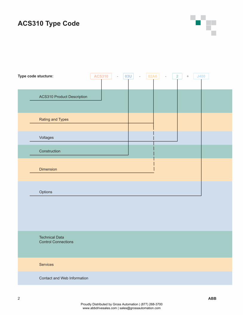
ACS310 Type Code
Type code stucture:
ACS310 Product Description
Rating and Types
Voltages
Construction
Dimension
Options
Technical DataControl Connections
Services
Contact and Web Information
ACS310 - 03U - 02A6 - 2 + J400
Proudly Distributed by Gross Automation | (877) 268-3700 www.abbdrivesales.com | [email protected]
3ABB
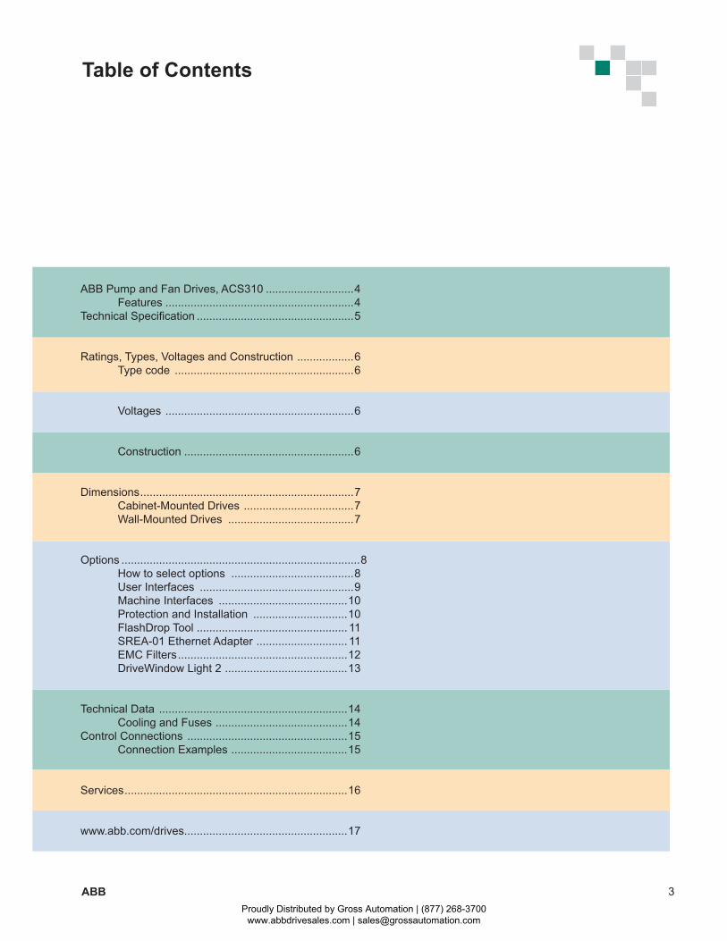
Table of Contents
ABB Pump and Fan Drives, ACS310 ............................4 Features ............................................................4Technical Specification ..................................................5
Ratings, Types, Voltages and Construction ..................6 Type code .........................................................6
Voltages ............................................................6
Construction ......................................................6
Dimensions ....................................................................7 Cabinet-Mounted Drives ...................................7 Wall-Mounted Drives ........................................7
Options ............................................................................ 8 How to select options .......................................8 User Interfaces .................................................9 Machine Interfaces .........................................10 Protection and Installation ..............................10 FlashDrop Tool ................................................ 11 SREA-01 Ethernet Adapter ............................. 11 EMC Filters ......................................................12 DriveWindow Light 2 .......................................13
Technical Data ............................................................14 Cooling and Fuses ..........................................14Control Connections ...................................................15 Connection Examples .....................................15
Services .......................................................................16
www.abb.com/drives....................................................17
Proudly Distributed by Gross Automation | (877) 268-3700 www.abbdrivesales.com | [email protected]
4 ABB
Feature Advantage BenefitPump and fan control (PFC) macro to control pumps and fans in parallel
One drive controls several pumps or fans and eliminates the need for an external programmable logic controller.
Reduces motor stress and increases lifetime when auxiliary motors are driven according to the needed pump/fan capacity.
Interlock function enables one motor to be disengaged from the mains supply while others continue operating in parallel.
Saves cost of additional drives and external PLC.
Longer life for pump or fan system while reducing maintenance time and costs.
Maintenance can be carried out safely without stopping process.
Soft pump and fan control macro (SPFC)
Reduces unwanted pressure peaks in pumps and pipelines when an auxiliary motor is started.
Reduces maintenance costs.Longer life for pump or fan system.Smoother processes.
Pump protection functions Improved protection with pre-programmed features for preventive maintenance.Helps avoid corrosion in the pump systems.
Reduces maintenance costs.Longer life for pump system.
Pump Cleaning Use of external control (relay logic, timers & contactors) are not needed as the functionality is built-in.
Reduces users overall machine costs.
Embedded Modbus RS-485 fieldbus interface
No need for external fieldbus options. Integrated and compact design.
Saves costs of external fieldbus devices.Increases reliability.
On/off cooling fan control Cooling fan rotates only when the drive is modulating, thereby cooling only when needed.
Silent operation.Improves drive’s energy efficiency.
Software controlled phase inversion
Fast and easy way to change the phase order of the motor rotation.
Time savings as there is no need to change the output cable order manually.
Short parameter menu view Only the most needed drive parameters are shown on the drive’s parameter view. Complete parameter view can be changed by setting one parameter.
Time savings as user can quickly see the most important parameters. Fast commissioning of the drive.
Energy optimizer Improved motor efficiency with intelligent drive control method, especially while operating on partial loads.
Boosts energy efficiency due to lower motor currents. Reduces audible noise from the motor.
Energy efficiency tools Several tools to illustrate saved energy (kWh), carbon-dioxide emissions (CO2) and cost in local currency.
Shows direct impact on energy bill and helps control operational expenditure (OPEX).
Full output current at 50 °C ambient
Drive can be operated in ambient temperatures up to 50 °C without derating the output current.
Optimized drive dimensioning for wide temperature range.
Load analyzer Load analyzer saves process data, such as current and torque values, which can be used to analyze the process and dimensioning of the drive and motor.
Optimized dimensioning of the drive, motor and process.
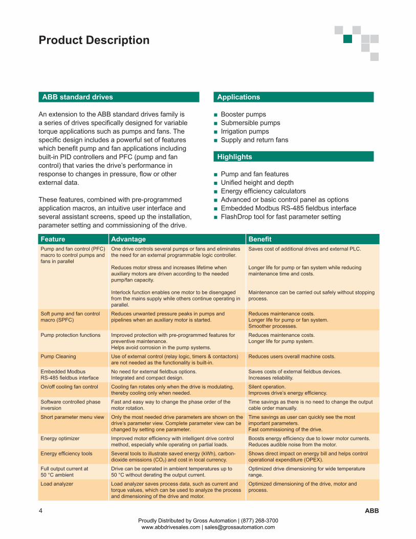
Product Description
ABB standard drives
An extension to the ABB standard drives family is a series of drives specifically designed for variable torque applications such as pumps and fans. The specific design includes a powerful set of features which benefit pump and fan applications including built-in PID controllers and PFC (pump and fan control) that varies the drive’s performance in response to changes in pressure, flow or other external data.
These features, combined with pre-programmed application macros, an intuitive user interface and several assistant screens, speed up the installation, parameter setting and commissioning of the drive.
Applications
Booster pumps Submersible pumps Irrigation pumps Supply and return fans
Highlights
Pump and fan features Unified height and depth Energy efficiency calculators Advanced or basic control panel as options Embedded Modbus RS-485 fieldbus interface FlashDrop tool for fast parameter setting
Proudly Distributed by Gross Automation | (877) 268-3700 www.abbdrivesales.com | [email protected]
5ABB
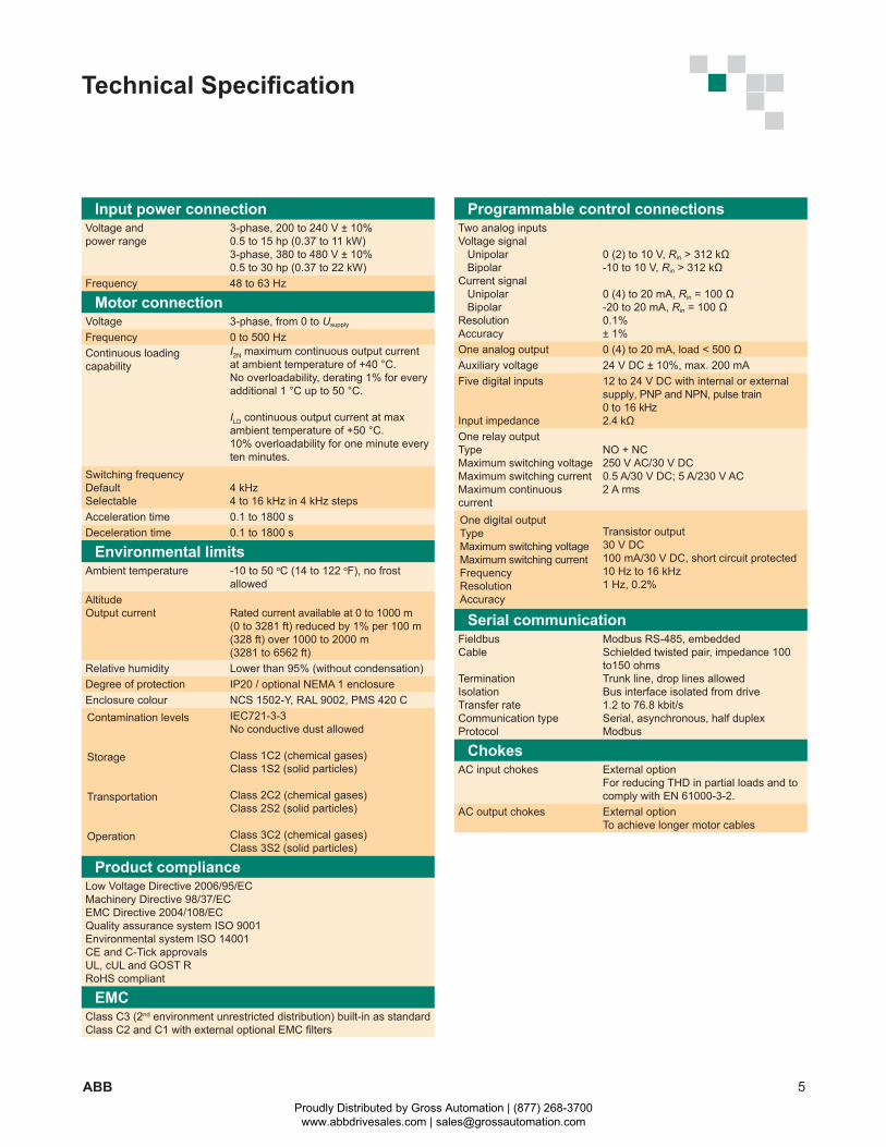
Input power connectionVoltage and power range
3-phase, 200 to 240 V ± 10% 0.5 to 15 hp (0.37 to 11 kW) 3-phase, 380 to 480 V ± 10% 0.5 to 30 hp (0.37 to 22 kW)
Frequency 48 to 63 Hz
Motor connectionVoltage 3-phase, from 0 to Usupply
Frequency 0 to 500 HzContinuous loadingcapability
I2N maximum continuous output current at ambient temperature of +40 °C. No overloadability, derating 1% for every additional 1 °C up to 50 °C.
ILD continuous output current at max ambient temperature of +50 °C.10% overloadability for one minute every ten minutes.
Switching frequencyDefaultSelectable
4 kHz4 to 16 kHz in 4 kHz steps
Acceleration time 0.1 to 1800 sDeceleration time 0.1 to 1800 s
Environmental limitsAmbient temperature -10 to 50 oC (14 to 122 oF), no frost
allowed AltitudeOutput current Rated current available at 0 to 1000 m
(0 to 3281 ft) reduced by 1% per 100 m (328 ft) over 1000 to 2000 m (3281 to 6562 ft)
Relative humidity Lower than 95% (without condensation)Degree of protection IP20 / optional NEMA 1 enclosureEnclosure colour NCS 1502-Y, RAL 9002, PMS 420 CContamination levels
Storage
Transportation
Operation
IEC721-3-3No conductive dust allowed Class 1C2 (chemical gases)Class 1S2 (solid particles)
Class 2C2 (chemical gases) Class 2S2 (solid particles)
Class 3C2 (chemical gases) Class 3S2 (solid particles)
Product complianceLow Voltage Directive 2006/95/EC Machinery Directive 98/37/EC EMC Directive 2004/108/EC Quality assurance system ISO 9001Environmental system ISO 14001 CE and C-Tick approvalsUL, cUL and GOST R RoHS compliant
EMCClass C3 (2nd environment unrestricted distribution) built-in as standardClass C2 and C1 with external optional EMC filters
Programmable control connectionsTwo analog inputsVoltage signal Unipolar BipolarCurrent signal Unipolar BipolarResolutionAccuracy
0 (2) to 10 V, Rin > 312 kΩ-10 to 10 V, Rin > 312 kΩ
0 (4) to 20 mA, Rin = 100 Ω-20 to 20 mA, Rin = 100 Ω0.1%± 1%
One analog output 0 (4) to 20 mA, load < 500 ΩAuxiliary voltage 24 V DC ± 10%, max. 200 mAFive digital inputs
Input impedance
12 to 24 V DC with internal or external supply, PNP and NPN, pulse train 0 to 16 kHz 2.4 kΩ
One relay outputTypeMaximum switching voltageMaximum switching currentMaximum continuous current
NO + NC250 V AC/30 V DC0.5 A/30 V DC; 5 A/230 V AC2 A rms
One digital outputTypeMaximum switching voltageMaximum switching currentFrequencyResolutionAccuracy
Transistor output30 V DC100 mA/30 V DC, short circuit protected10 Hz to 16 kHz1 Hz, 0.2%
Serial communicationFieldbusCable
TerminationIsolationTransfer rateCommunication typeProtocol
Modbus RS-485, embeddedSchielded twisted pair, impedance 100 to150 ohmsTrunk line, drop lines allowedBus interface isolated from drive1.2 to 76.8 kbit/sSerial, asynchronous, half duplexModbus
ChokesAC input chokes External option
For reducing THD in partial loads and to comply with EN 61000-3-2.
AC output chokes External option To achieve longer motor cables
Technical Specification
Proudly Distributed by Gross Automation | (877) 268-3700 www.abbdrivesales.com | [email protected]
6 ABB
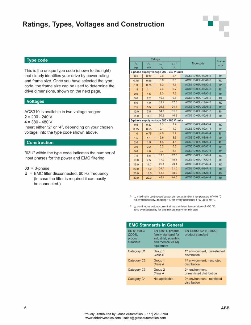
RatingsType code
FramesizePN
HpPN
kWI2N
1)
AILD
2)
A3-phase supply voltage 200 - 240 V units
0.5 0.37 2.6 2.4 ACS310-03U-02A6-2 R00.75 0.55 3.9 3.5 ACS310-03U-03A9-2 R01.0 0.75 5.2 4.7 ACS310-03U-05A2-2 R11.5 1.1 7.4 6.7 ACS310-03U-07A4-2 R12.0 1.5 8.3 7.5 ACS310-03U-08A3-2 R13.0 2.2 10.8 9.8 ACS310-03U-10A8-2 R25.0 4.0 19.4 17.6 ACS310-03U-19A4-2 R27.5 5.5 26.8 24.4 ACS310-03U-26A8-2 R3
10.0 7.5 34.1 31.0 ACS310-03U-34A1-2 R415.0 11.0 50.8 46.2 ACS310-03U-50A8-2 R4
3-phase supply voltage 380 - 480 V units0.5 0.37 1.3 1.2 ACS310-03U-01A3-4 R00.75 0.55 2.1 1.9 ACS310-03U-02A1-4 R01.0 0.75 2.6 2.4 ACS310-03U-02A6-4 R11.5 1.1 3.6 3.3 ACS310-03U-03A6-4 R12.0 1.5 4.5 4.1 ACS310-03U-04A5-4 R13.0 2.2 6.2 5.6 ACS310-03U-06A2-4 R15.0 4.0 9.7 8.8 ACS310-03U-09A7-4 R17.5 5.5 13.8 12.5 ACS310-03U-13A8-4 R310.0 7.5 17.2 15.6 ACS310-03U-17A2-4 R315.0 11.0 25.4 23.1 ACS310-03U-25A4-4 R320.0 15.0 34.1 31.0 ACS310-03U-034A-1 R425.0 18.5 41.8 38.0 ACS310-03U-41A8-4 R430.0 22.0 48.4 44.0 ACS310-03U-48A4-4 R4
EMC Standards in GeneralEN 61800-3 (2004),product standard
EN 55011, product family standard for industrial, scientific and medical (ISM) equipment
EN 61800-3/A11 (2000), product standard
Category C1 Group 1 Class B
1st environment, unrestricted distribution
Category C2 Group 1 Class A
1st environment, restricted distribution
Category C3 Group 2Class A
2nd environment, unrestricted distribution
Category C4 Not applicable 2nd environment, restricted distribution
Ratings, Types, Voltages and Construction
Type code
This is the unique type code (shown to the right) that clearly identifies your drive by power rating and frame size. Once you have selected the type code, the frame size can be used to determine the drive dimensions, shown on the next page.
Voltages
ACS310 is available in two voltage ranges:2 = 200 - 240 V4 = 380 - 480 VInsert either "2" or “4”, depending on your chosen voltage, into the type code shown above.
Construction
"03U" within the type code indicates the number of input phases for the power and EMC filtering.
03 = 3-phaseU = EMC filter disconnected, 60 Hz frequency (In case the filter is required it can easily be connected.)
1) I2N maximum continuous output current at ambient temperature of +40 °C. No overloadability, derating 1% for every additional 1 °C up to 50 °C.
2) ILD continuous output current at max ambient temperature of +50 °C. 10% overloadability for one minute every ten minutes.
Proudly Distributed by Gross Automation | (877) 268-3700 www.abbdrivesales.com | [email protected]
7ABB
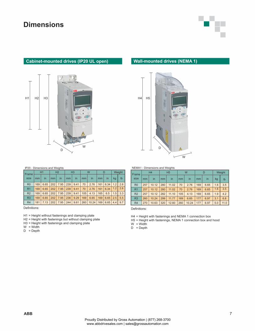
H1 H2 H3 H4 H5
DW
W
D
IP20 - Dimensions and Weights
Frame size
H1 H2 H3 W D Weight
mm in mm in mm in mm in mm in kg lb
R0 169 6.65 202 7.95 239 9.41 70 2.76 161 6.34 1.2 2.6R1 169 6.65 202 7.95 239 9.41 70 2.76 161 6.34 1.2 2.6
R2 169 6.65 202 7.95 239 9.41 105 4.13 165 6.5 1.5 3.3R3 169 6.65 202 7.95 236 9.29 169 6.65 169 6.65 2.5 5.5R4 181 7.13 202 7.95 244 9.61 260 10.24 169 6.65 4.4 9.7
NEMA1 - Dimensions and Weights
Frame size
H4 H5 W D Weight
mm in mm in mm in mm in kg lb
R0 257 10.12 280 11.02 70 2.76 169 6.65 1.6 3.5R1 257 10.12 280 11.02 70 2.76 169 6.65 1.6 3.5
R2 257 10.12 282 11.10 105 4.13 169 6.65 1.9 4.2R3 260 10.24 299 11.77 169 6.65 177 6.97 3.1 6.8R4 270 10.63 320 12.60 260 10.24 177 6.97 5.0 11.0
Definitions:
H1 = Height without fastenings and clamping plateH2 = Height with fastenings but without clamping plateH3 = Height with fastenings and clamping plateW = WidthD = Depth
Definitions:
H4 = Height with fastenings and NEMA 1 connection boxH5 = Height with fastenings, NEMA 1 connection box and hoodW = WidthD = Depth
Dimensions
Cabinet-mounted drives (IP20 UL open) Wall-mounted drives (NEMA 1)
Proudly Distributed by Gross Automation | (877) 268-3700 www.abbdrivesales.com | [email protected]
8 ABB
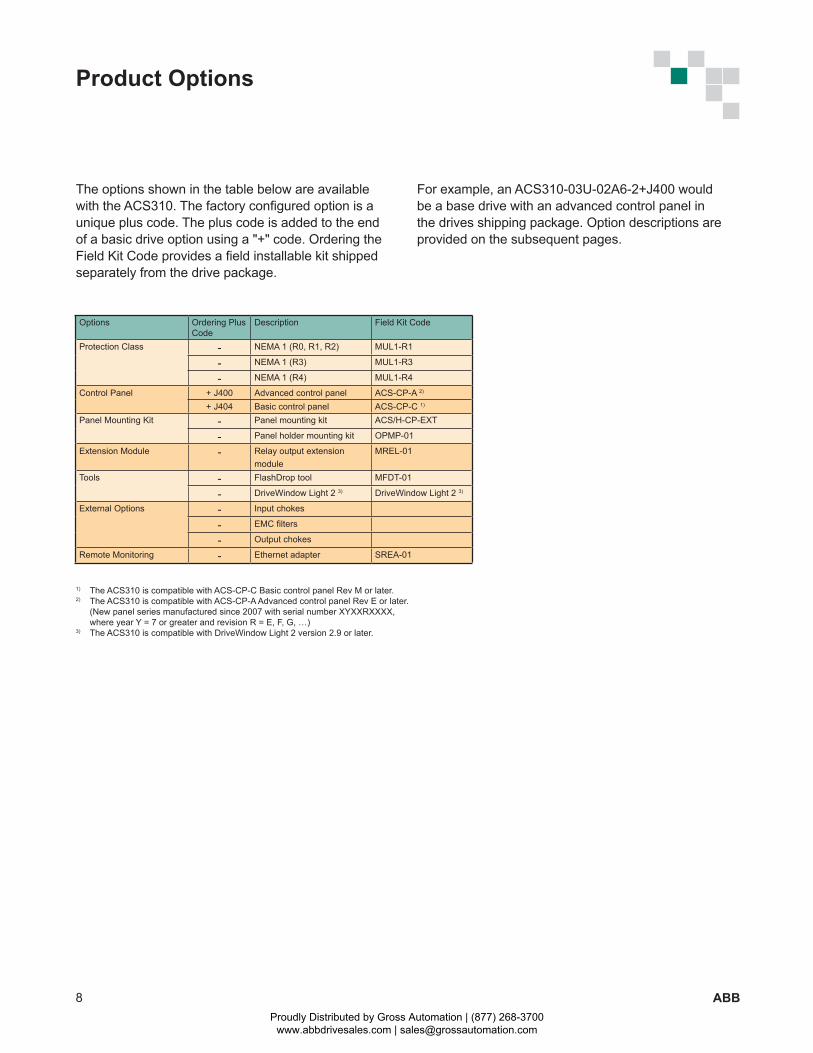
Options Ordering Plus Code
Description Field Kit Code
Protection Class - NEMA 1 (R0, R1, R2) MUL1-R1
- NEMA 1 (R3) MUL1-R3
- NEMA 1 (R4) MUL1-R4
Control Panel + J400 Advanced control panel ACS-CP-A 2)
+ J404 Basic control panel ACS-CP-C 1)
Panel Mounting Kit - Panel mounting kit ACS/H-CP-EXT
- Panel holder mounting kit OPMP-01
Extension Module - Relay output extension module
MREL-01
Tools - FlashDrop tool MFDT-01
- DriveWindow Light 2 3) DriveWindow Light 2 3)
External Options - Input chokes
- EMC filters
- Output chokes
Remote Monitoring - Ethernet adapter SREA-01
Product Options
The options shown in the table below are available with the ACS310. The factory configured option is a unique plus code. The plus code is added to the end of a basic drive option using a "+" code. Ordering the Field Kit Code provides a field installable kit shipped separately from the drive package.
1) The ACS310 is compatible with ACS-CP-C Basic control panel Rev M or later.2) The ACS310 is compatible with ACS-CP-A Advanced control panel Rev E or later. (New panel series manufactured since 2007 with serial number XYXXRXXXX, where year Y = 7 or greater and revision R = E, F, G, …)3) The ACS310 is compatible with DriveWindow Light 2 version 2.9 or later.
For example, an ACS310-03U-02A6-2+J400 would be a base drive with an advanced control panel in the drives shipping package. Option descriptions are provided on the subsequent pages.
Proudly Distributed by Gross Automation | (877) 268-3700 www.abbdrivesales.com | [email protected]
9ABB
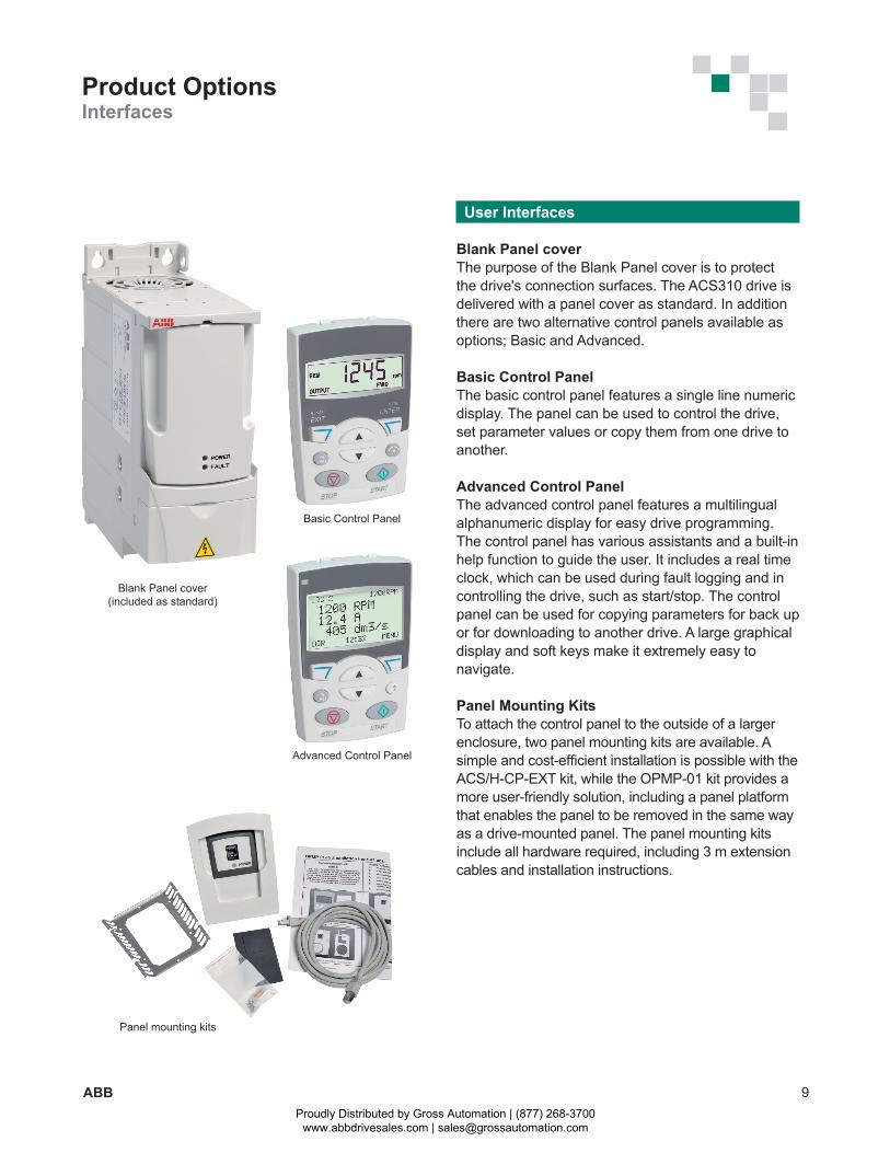
User Interfaces
Blank Panel coverThe purpose of the Blank Panel cover is to protect the drive's connection surfaces. The ACS310 drive is delivered with a panel cover as standard. In addition there are two alternative control panels available as options; Basic and Advanced.
Basic Control PanelThe basic control panel features a single line numeric display. The panel can be used to control the drive, set parameter values or copy them from one drive to another.
Advanced Control PanelThe advanced control panel features a multilingual alphanumeric display for easy drive programming. The control panel has various assistants and a built-in help function to guide the user. It includes a real time clock, which can be used during fault logging and in controlling the drive, such as start/stop. The control panel can be used for copying parameters for back up or for downloading to another drive. A large graphical display and soft keys make it extremely easy to navigate.
Panel Mounting KitsTo attach the control panel to the outside of a larger enclosure, two panel mounting kits are available. A simple and cost-efficient installation is possible with the ACS/H-CP-EXT kit, while the OPMP-01 kit provides a more user-friendly solution, including a panel platform that enables the panel to be removed in the same way as a drive-mounted panel. The panel mounting kits include all hardware required, including 3 m extension cables and installation instructions.
Product OptionsInterfaces
Blank Panel cover(included as standard)
Basic Control Panel
Advanced Control Panel
Panel mounting kits
Proudly Distributed by Gross Automation | (877) 268-3700 www.abbdrivesales.com | [email protected]
10 ABB
Product OptionsInterfaces
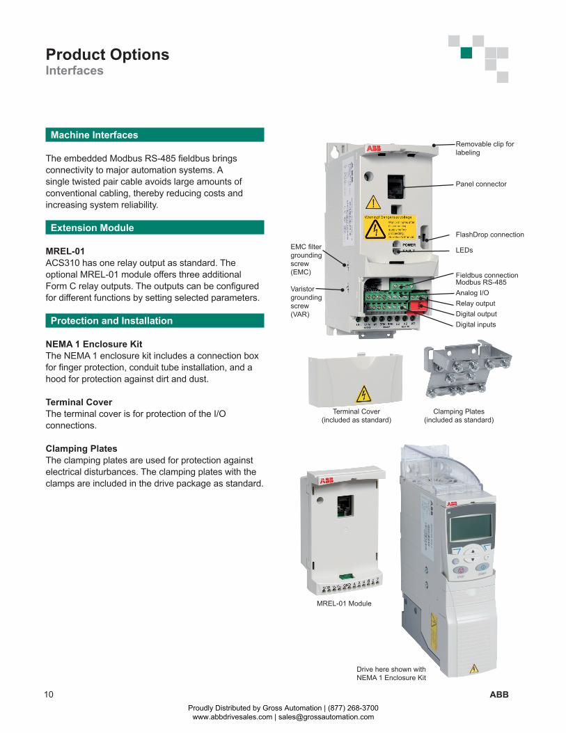
Clamping Plates(included as standard)
Terminal Cover(included as standard)
FlashDrop connection
Fieldbus connection Modbus RS-485Analog I/ORelay outputDigital outputDigital inputs
LEDs
Panel connector
EMC filter grounding screw (EMC)
Varistor grounding screw (VAR)
Removable clip for labeling
Machine Interfaces
The embedded Modbus RS-485 fieldbus bringsconnectivity to major automation systems. A single twisted pair cable avoids large amounts of conventional cabling, thereby reducing costs and increasing system reliability.
Extension Module
MREL-01ACS310 has one relay output as standard. The optional MREL-01 module offers three additional Form C relay outputs. The outputs can be configured for different functions by setting selected parameters.
Protection and Installation
NEMA 1 Enclosure KitThe NEMA 1 enclosure kit includes a connection box for finger protection, conduit tube installation, and a hood for protection against dirt and dust.
Terminal CoverThe terminal cover is for protection of the I/O connections.
Clamping PlatesThe clamping plates are used for protection against electrical disturbances. The clamping plates with the clamps are included in the drive package as standard.
MREL-01 Module
Drive here shown with NEMA 1 Enclosure Kit
Proudly Distributed by Gross Automation | (877) 268-3700 www.abbdrivesales.com | [email protected]
11ABB
Product OptionsExternal
A separate order line and type code is required for any of these external options.
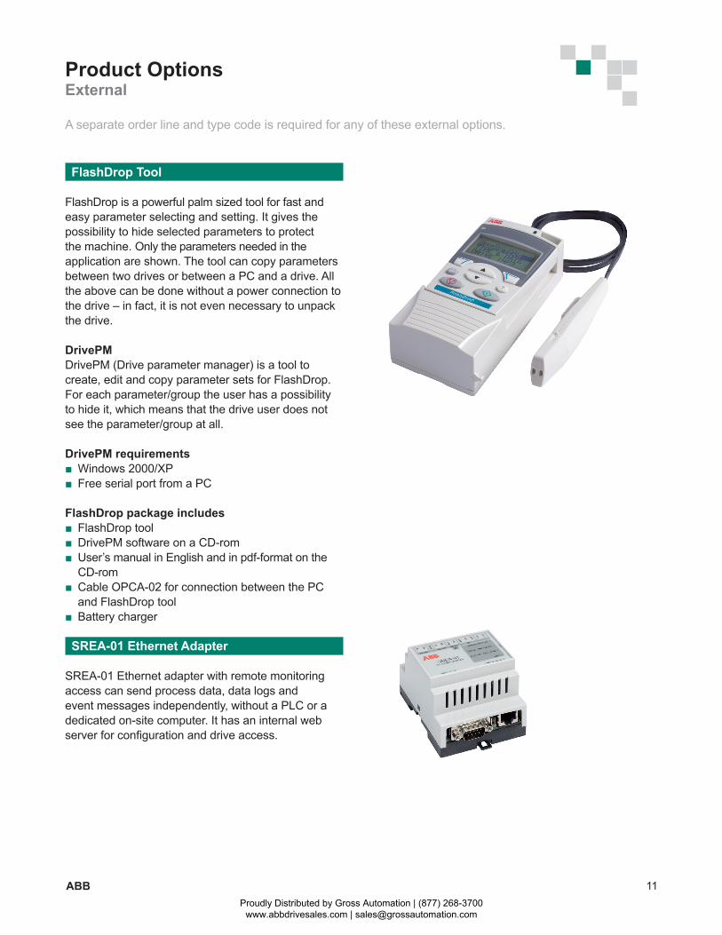
FlashDrop Tool
FlashDrop is a powerful palm sized tool for fast and easy parameter selecting and setting. It gives the possibility to hide selected parameters to protect the machine. Only the parameters needed in the application are shown. The tool can copy parameters between two drives or between a PC and a drive. All the above can be done without a power connection to the drive – in fact, it is not even necessary to unpack the drive.
DrivePMDrivePM (Drive parameter manager) is a tool to create, edit and copy parameter sets for FlashDrop. For each parameter/group the user has a possibility to hide it, which means that the drive user does not see the parameter/group at all.
DrivePM requirements Windows 2000/XP Free serial port from a PC
FlashDrop package includes FlashDrop tool DrivePM software on a CD-rom User’s manual in English and in pdf-format on the
CD-rom Cable OPCA-02 for connection between the PC
and FlashDrop tool Battery charger
SREA-01 Ethernet Adapter
SREA-01 Ethernet adapter with remote monitoring access can send process data, data logs and event messages independently, without a PLC or a dedicated on-site computer. It has an internal web server for configuration and drive access.
Proudly Distributed by Gross Automation | (877) 268-3700 www.abbdrivesales.com | [email protected]
12 ABB
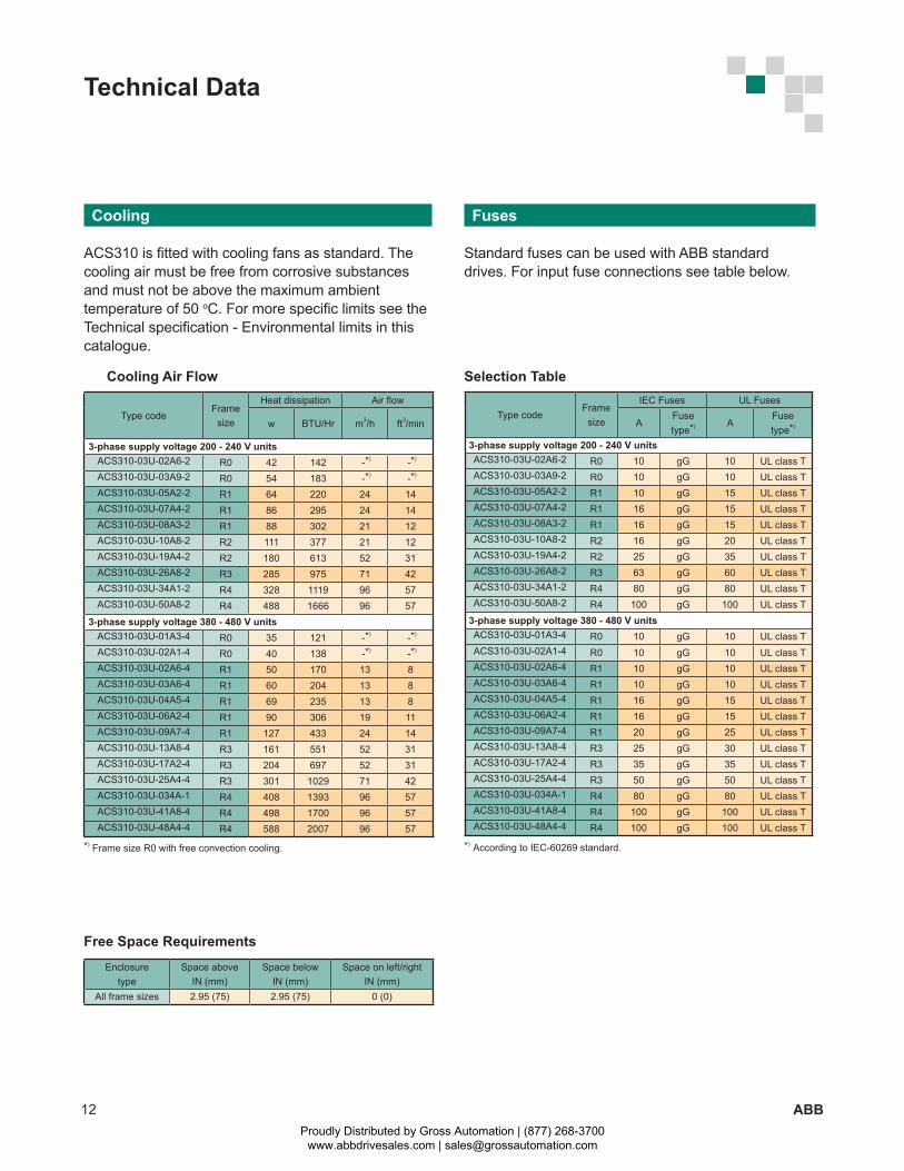
Type codeFramesize
IEC Fuses UL Fuses
AFusetype*) A
Fusetype*)
3-phase supply voltage 200 - 240 V unitsACS310-03U-02A6-2 R0 10 gG 10 UL class TACS310-03U-03A9-2 R0 10 gG 10 UL class TACS310-03U-05A2-2 R1 10 gG 15 UL class TACS310-03U-07A4-2 R1 16 gG 15 UL class TACS310-03U-08A3-2 R1 16 gG 15 UL class TACS310-03U-10A8-2 R2 16 gG 20 UL class TACS310-03U-19A4-2 R2 25 gG 35 UL class TACS310-03U-26A8-2 R3 63 gG 60 UL class TACS310-03U-34A1-2 R4 80 gG 80 UL class TACS310-03U-50A8-2 R4 100 gG 100 UL class T
3-phase supply voltage 380 - 480 V unitsACS310-03U-01A3-4 R0 10 gG 10 UL class TACS310-03U-02A1-4 R0 10 gG 10 UL class TACS310-03U-02A6-4 R1 10 gG 10 UL class TACS310-03U-03A6-4 R1 10 gG 10 UL class TACS310-03U-04A5-4 R1 16 gG 15 UL class TACS310-03U-06A2-4 R1 16 gG 15 UL class TACS310-03U-09A7-4 R1 20 gG 25 UL class TACS310-03U-13A8-4 R3 25 gG 30 UL class TACS310-03U-17A2-4 R3 35 gG 35 UL class TACS310-03U-25A4-4 R3 50 gG 50 UL class TACS310-03U-034A-1 R4 80 gG 80 UL class TACS310-03U-41A8-4 R4 100 gG 100 UL class TACS310-03U-48A4-4 R4 100 gG 100 UL class T
Enclosuretype
Space aboveIN (mm)
Space belowIN (mm)
Space on left/rightIN (mm)
All frame sizes 2.95 (75) 2.95 (75) 0 (0)
Type codeFramesize
Heat dissipation Air flow
w BTU/Hr m3/h ft3/min
3-phase supply voltage 200 - 240 V unitsACS310-03U-02A6-2 R0 42 142 -*) -*)
ACS310-03U-03A9-2 R0 54 183 -*) -*)
ACS310-03U-05A2-2 R1 64 220 24 14ACS310-03U-07A4-2 R1 86 295 24 14ACS310-03U-08A3-2 R1 88 302 21 12ACS310-03U-10A8-2 R2 111 377 21 12ACS310-03U-19A4-2 R2 180 613 52 31ACS310-03U-26A8-2 R3 285 975 71 42ACS310-03U-34A1-2 R4 328 1119 96 57ACS310-03U-50A8-2 R4 488 1666 96 57
3-phase supply voltage 380 - 480 V unitsACS310-03U-01A3-4 R0 35 121 -*) -*)
ACS310-03U-02A1-4 R0 40 138 -*) -*)
ACS310-03U-02A6-4 R1 50 170 13 8ACS310-03U-03A6-4 R1 60 204 13 8ACS310-03U-04A5-4 R1 69 235 13 8ACS310-03U-06A2-4 R1 90 306 19 11ACS310-03U-09A7-4 R1 127 433 24 14ACS310-03U-13A8-4 R3 161 551 52 31ACS310-03U-17A2-4 R3 204 697 52 31ACS310-03U-25A4-4 R3 301 1029 71 42ACS310-03U-034A-1 R4 408 1393 96 57ACS310-03U-41A8-4 R4 498 1700 96 57ACS310-03U-48A4-4 R4 588 2007 96 57
Fuses
Standard fuses can be used with ABB standard drives. For input fuse connections see table below.
Selection Table
Free Space Requirements
Cooling Air Flow
Cooling
ACS310 is fitted with cooling fans as standard. The cooling air must be free from corrosive substances and must not be above the maximum ambient temperature of 50 oC. For more specific limits see the Technical specification - Environmental limits in this catalogue.
*) Frame size R0 with free convection cooling. *) According to IEC-60269 standard.
Technical Data
Proudly Distributed by Gross Automation | (877) 268-3700 www.abbdrivesales.com | [email protected]
13ABB
+24 VGND
DCOMDI1DI2DI3DI4DI5
910111213141516
910111213141516
+24 VGND
DCOMDI1DI2DI3DI4DI5
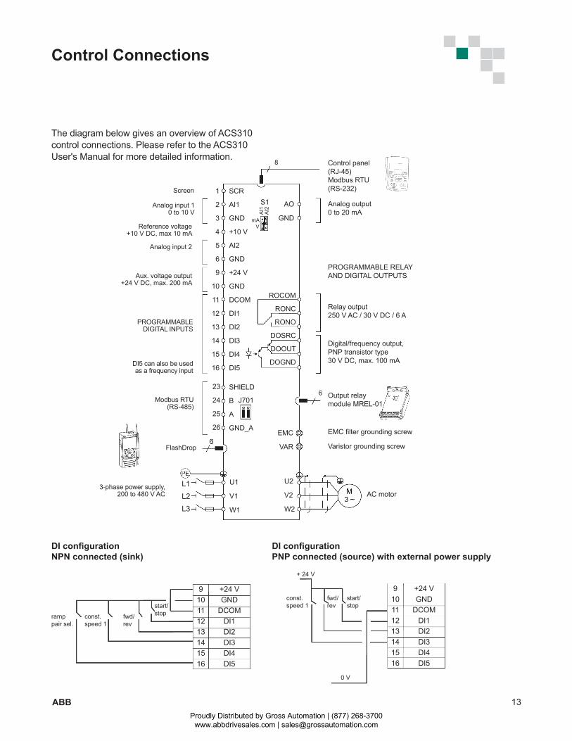
DI confi guration PNP connected (source) with external power supply
DI confi guration NPN connected (sink)
ramppair sel.
const.speed 1
fwd/rev
start/stop
const.speed 1
fwd/rev
start/stop
+ 24 V
0 V
SCR
AI1
GND
+10 V
AI2
GND
+24 V
GND
DCOM
DI1
DI2
DI3
DI4
DI5
U1
V1
W1
AO
GND
ROCOM
RONC
RONO
DOSRC
DOOUT
DOGND
EMC
VAR
U2
V2
W2
Control panel(RJ-45)Modbus RTU (RS-232)
L1L2L3
AC motor
Analog output 0 to 20 mA
PROGRAMMABLE RELAYAND DIGITAL OUTPUTS
Relay output250 V AC / 30 V DC / 6 A
Digital/frequency output,PNP transistor type30 V DC, max. 100 mA
EMC fi lter grounding screw
Varistor grounding screw
Screen
8
Analog input 1 0 to 10 V
Reference voltage+10 V DC, max 10 mA
Analog input 2
Aux. voltage output+24 V DC, max. 200 mA
PROGRAMMABLE DIGITAL INPUTS
FlashDrop
Modbus RTU (RS-485)
3-phase power supply,200 to 480 V AC
AI1
AI2
mAV
Output relaymodule MREL-01
S11
2
3
4
5
6
9
10
11
12
13
14
15
16
23
24
25
26
SHIELD
B
A
GND_A
J7016
DI5 can also be usedas a frequency input
Control Connections
The diagram below gives an overview of ACS310 control connections. Please refer to the ACS310 User's Manual for more detailed information.
Proudly Distributed by Gross Automation | (877) 268-3700 www.abbdrivesales.com | [email protected]
14 ABB
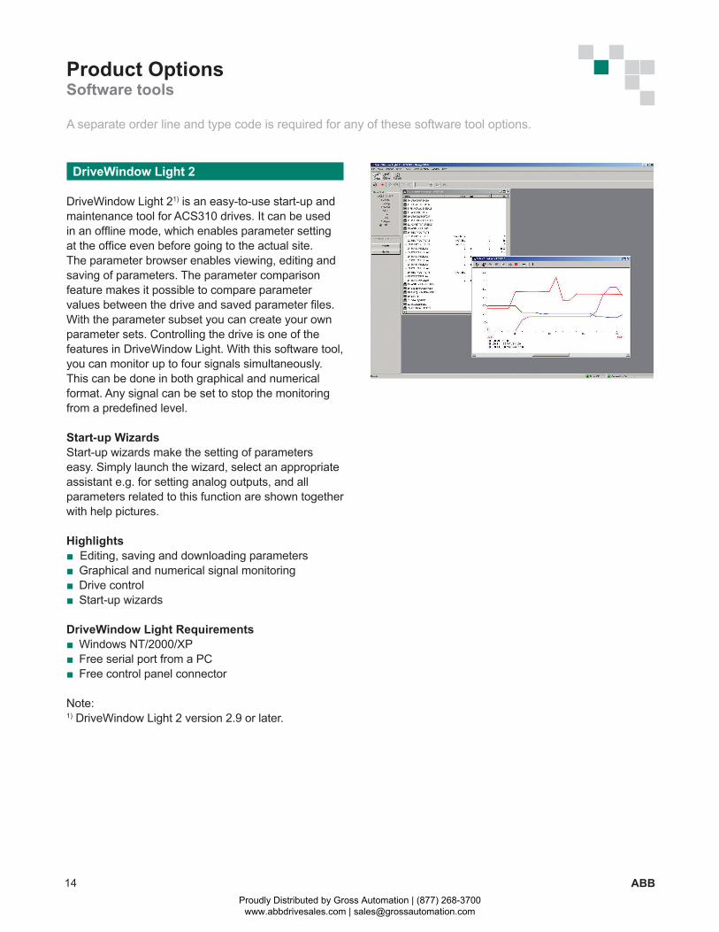
DriveWindow Light 2
DriveWindow Light 21) is an easy-to-use start-up and maintenance tool for ACS310 drives. It can be used in an offline mode, which enables parameter setting at the office even before going to the actual site. The parameter browser enables viewing, editing and saving of parameters. The parameter comparison feature makes it possible to compare parameter values between the drive and saved parameter files. With the parameter subset you can create your own parameter sets. Controlling the drive is one of the features in DriveWindow Light. With this software tool, you can monitor up to four signals simultaneously. This can be done in both graphical and numerical format. Any signal can be set to stop the monitoring from a predefined level.
Start-up WizardsStart-up wizards make the setting of parameters easy. Simply launch the wizard, select an appropriate assistant e.g. for setting analog outputs, and all parameters related to this function are shown together with help pictures.
Highlights Editing, saving and downloading parameters Graphical and numerical signal monitoring Drive control Start-up wizards
DriveWindow Light Requirements Windows NT/2000/XP Free serial port from a PC Free control panel connector
Note:1) DriveWindow Light 2 version 2.9 or later.
Product OptionsSoftware tools
A separate order line and type code is required for any of these software tool options.
Proudly Distributed by Gross Automation | (877) 268-3700 www.abbdrivesales.com | [email protected]

15ABB
Notes:
Proudly Distributed by Gross Automation | (877) 268-3700 www.abbdrivesales.com | [email protected]
AC
S31
0-P
HTC
01U
-EN
RE
VA. E
ffect
ive
05/3
1/20
09 S
ubje
ct to
cha
nge
with
out n
otic
e.ABB Inc. Low Voltage Drives16250 W. Glendale Drive New Berlin, WI 53151 USA Phone: (800) 752-0696 Fax: (262) 785-0397 Web: www.abb.us/drives ABB Inc. Low Voltage Drives- Canada3299 J.B. Deschamps Blvd Lachine, Quebec H8T 3E4 Phone: (800) 215-3066 Fax: (514) 420- 3137 Web: www.abb.com
Contact us
Proudly Distributed by Gross Automation | (877) 268-3700 www.abbdrivesales.com | [email protected]


