47
Technical Catalogue Relays Timer Relays Monitoring Relays Motor Protection Relays

Technical Catalogue RelaysTimer Relays
Monitoring Relays
Motor Protection Relays
3ABB STOTZ-KONTAKT GmbH1SAC 1008 01 D0201
Contents
Electronic time relays, Series C 560 ...................................................................................................................................... 5
Selection, technical data, ordering details ...................................................................................................................... 6
Function table, device wiring diagrams ............................................................................................................................ 8
Technical data ................................................................................................................................................................................ 12
Dimensions diagrams ................................................................................................................................................................ 13
Monitoring relays, Series C 55x/C 58 .................................................................................................................................... 15
Selection table ............................................................................................................................................................................... 17
Technical data, ordering details ........................................................................................................................................... 18
Wiring diagrams, connection diagrams ............................................................................................................................ 30
Dimensions diagrams ................................................................................................................................................................ 32
Insulation monitoring device and Earth-leakage monitor ....................................................................................... 33
Wiring diagrams, dimension diagrams ............................................................................................................................. 37
Machine protection Custorapid ® .............................................................................................................................................. 39
Ordering details ............................................................................................................................................................................. 40
General information ..................................................................................................................................................................... 42
Technical data ................................................................................................................................................................................ 43
PTB, Approvals ............................................................................................................................................................................. 44
Connection examples, function diagramms .................................................................................................................. 45
Dimensions diagrams ................................................................................................................................................................ 47
Relays

41SAC 1008 01 D0201
ABB STOTZ-KONTAKT GmbH

5ABB STOTZ-KONTAKT GmbH1SAC 1008 01 D0201
SS
R00
397
SS
T00
597
SS
T01
197
Electronic time relays
Standards and regulationsThe time relays comply with:
• IEC 721-3-3 "Ambient conditions"
• IEC 1812-1DIN VDE 0435, Part 2021"Electrical relays, Time Relays"
• IEC 1000 "Electromagnetic Compatibility"
• IEC 947-5-1; DIN BDE 0660, Part 200"Low-Voltage Switchgear Devices"
Scope of applicationTime relays are used for all time-delayed switching operations in control, starting, protectiveand regulating circuits. They guarantee a high repeat accuracy of operating times, once set.
Customer benefits are:
• industrial design
• high accuracy
• high reliability
• easy handling
Housing designAll time relays are suitable for snap-on mounting on 35 mm top-hat rails to DIN EN 50 022 orscrew mounting.

61SAC 1008 01 D0201
ABB STOTZ-KONTAKT GmbH
Electronic time relays, Series C 56xSelection, technical data, ordering details
Time range t Rated control supply Order code Price Weight Packingvoltage per unit
with rotary switch, AC 50/60 Hz DC piececan be set to V V kg piece
C 561.10 time relay, ON-delayed, 1 time range, 1 changeover contact, with 2 LEDs
0.5 - 10 s 24/100 - 127 24 1SAR 310 011 R 0001 0.100 124/200 - 240 24 1SAR 310 011 R 0002 0.100 1
1.5 - 30 s 24/100 - 127 24 1SAR 310 012 R 0001 0.100 124/200 - 240 24 1SAR 310 012 R 0002 0.100 1
5 - 100 s 24/100 - 127 24 1SAR 310 013 R 0001 0.100 124/200 - 240 24 1SAR 310 013 R 0002 0.100 1
C 561.01 time relay, ON-delayed, 15 time ranges, 2 changeover contacts, with 2 LEDs
0.05 - 1 s 24/100 - 127 24 1SAR 310 020 R 0001 0.110 10.15 - 3 s 24/200 - 240 24 1SAR 310 020 R 0002 0.110 10.5 - 10 s1.5 - 30 s
0.05 - 1 min5 - 100 s0.15 - 3 min0.5 - 10 min
1.5 - 30 min0.05 - 1 h5 - 100 min0.15 - 3 h
0.5 - 10 h1.5 - 30 h1 - 100 h
C 561.02 time relay, ON-delayed, 2-wire version, 4 time ranges
0.05 - 1 s 24 - 66 24 - 66 1SAR 370 006 R 0004 0.100 10.2 - 4 s 90 - 240 90 - 240 1SAR 370 006 R 0005 0.100 11.5 - 30 s
12 - 256 s
C 561.13 time relay, star-delta function, dead interval on reversing 50 ms, 1 time range,1 NO delayed, 1 NO undelayed
1 - 20 s 24/100 - 127 24 1SAR 360 014 R 0001 0.110 124/200 - 240 24 1SAR 360 014 R 0002 0.110 1
3 - 60 s 24/100 - 127 24 1SAR 360 015 R 0001 0.110 124/200 - 240 24 1SAR 360 015 R 0002 0.110
C 562.10 time relay, OFF-delayed, with auxiliary voltage, 1 time range, 1 changeover contact,with 2 LEDs
0.5 - 10 s 24/100 - 127 24 1SAR 320 011 R 0001 0.130 124/200 - 240 24 1SAR 320 011 R 0002 0.130 1
1.5 - 30 s 24/100 - 127 24 1SAR 320 012 R 0001 0.130 124/200 - 240 24 1SAR 320 012 R 0002 0.130 1
5 - 100 s 24/100 - 127 24 1SAR 320 013 R 0001 0.130 124/200 - 240 24 1SAR 320 013 R 0002 0.130 1
C 562.20 time relay, OFF-delayed, without auxiliary voltage, 1 changeover contact, 7 time ranges,with LED
0.05 - 1 s 24 24 1SAR 340 017 R 0006 0.130 10.15 - 3 s 100 - 127 100 - 127 1SAR 340 017 R 0007 0.130 10.3 - 6 s 200 - 240 200 - 240 1SAR 340 017 R 0008 0.130 10.5 - 10 s
1.5 - 30 s3 - 60 s5 - 100 s
SS
T 0
05 9
7
C 561.10
C 561.01
C 561.02
C 561.13
SS
T 0
08 9
7
C 562.20
C 562.10
SS
T 0
0697
SS
T 0
07 9
7S
ST
004
97
SS
T 0
0397

7ABB STOTZ-KONTAKT GmbH1SAC 1008 01 D0201
Electronic time relays, Series C 56xSelection, technical data, ordering details
SS
T 0
09 9
7S
ST
010
97
SS
T 0
11 9
7
C 563
C 565
C 564
Time range t Rated control supply Order code Price Weight Packingvoltage per unit
with rotary switch, AC 50/60 Hz DC piececan be set to V V kg piece
C 563, clock generator, 15 time ranges, 1 changeover contact, with 2 LEDs
0.05 - 1 s 24/100 - 127 24 1SAR 350 010 R 0001 0.110 10.15 - 3 s 24/200 - 240 24 1SAR 350 010 R 0002 0.110 1
0.5 - 10 s1.5 - 30 s
0.05 - 1 min5 - 100 s
0.15 - 3 min0.5 - 10 min
1.5 - 30 min0.05 - 1 h
5 - 100 min0.15 - 3 h
0.5 - 10 h1.5 - 30 h
1 - 100 h
C 564, Multi-function time relay, 1 time range, with 2 LEDs, 1 changeover contact, 8 functions,dual voltage
0.05 - 1 s0.15 - 3 s
0.5 - 10 s 24/100 - 127 24 1SAR 330 010 R 0001 0.140 11.5 - 30 s 24/200 - 240 24 1SAR 330 010 R 0002 0.140 1
0.05 - 1 min 24 - 240 1SAR 330 010 R 0000 0.140 1
5 - 100 s0.15 - 3 min
0.5 - 10 min
C 565, Multi-function time relay, 1 time range, with 2 LEDs, 2 changeover contact, 16 functions,dual voltage
1.5 - 30 min0.05 - 1 h
5 - 100 min 24/100 - 127 24 1SAR 330 020 R 0001 0.150 10,15 - 3 h 24/200 - 240 24 1SAR 330 020 R 0002 0.150 1
0,5 - 10 h 400 - 440 24 1SAR 330 020 R 0009 0.150 11,5 - 30 h 24 - 240 24 - 240 1SAR 330 020 R 0000 0.150 1
1 - 100 h
C 565-S, Multi-function time relay, 1 time range, with 2 LEDs, 2 changeover contact, positivelydriven, 16 functions, dual voltage
24 - 240 24 - 240 1SAR330 020 R 0000 0.150 1
C 566, time relay, OFF-delayed for DC coils
Delay dependent 200 - 240 1SAR 380 000 R 0008 0.200 1on coil power 100 - 127 1SAR 380 000 R 0007 0.200 1
C 560.10, cover cap sealable
for protecting against unauthorised 1SAR 390 000 R1000 5 setsreadjustment
C 560.20, plug-in tab for screw mounting
1SAR 390 000 R2000 5 sets
C 560.30, set of labels for multi-function relay C 564, full set with 8 functions
1SAR 390 000 R3000 0.020 5 sets
C 560.40, set of labels for multi-function relay C 565, full set with 16 functions
1SAR 390 000 R4000 0.020 5 sets
C 566
SS
T 0
39 9
7

81SAC 1008 01 D0201
ABB STOTZ-KONTAKT GmbH
L1
K2A1
A2K1
NNSK-6492
S1K1
B1
L1
S1
K2A1
A2K1
NNSK-6491a
B1
t
A1/A2
NS
2-51
5315/1815/16
t
25/2825/26
NS
K-7
579A1/A2
15/1815/16
t
NS
K-
7575A1/A2
A3 15
A2 1816
A1
AC/DC24V
AC100/127VAC200/240V
25
28 NS
K-7
610
26
Electronic time relays, Series C 56xFunction tables, device wiring diagrams
C 561.10ON-delayed with 1 changeo ver contact and 2 LEDs
Functions
Time relay energised
Contact element closed
Contact element open
C 561.01ON-delayed with 2 changeover contacts and 2 LEDs
C 561.02ON-delayed, 1 NO delayed, semiconductor
C 562.10OFF-delayed, 1 NO with 2 LEDs
A1/A2
15/1815/16
t
35ms
NS
K-
7576
B1/A2
>
C 562.20OFF-delay 1 changeover contact and LED
15/16
A1/A2
200 ms
t
15/18
NS
K-7
693
>
123451234512345
Project planning information• Changes to the time range and function take effect only if they
are made when de- energised.
Do not activate Start input B1 or B3 until supply voltage isapplied.
• Same potential applied to A1 and B1 or A3 and B3.
• Same potential applied to A1 and B1 or A3 and B3.In the case of dual-voltage versions, connect only on voltagerange in each case.
• In the case of AC, it is not permitted to control loads in parallelwith the Start input (see adjacent sketched circuit diagrams).
A3 15
A2 18 NS
K-
7606
16
A1
AC/DC24V
AC100/127VAC200/240V
A1+
A2
NS
2-50
88
Last
U
NS
K-7
60
7
AC/DC24V
AC100/127VAC200/240V
A1 15
A2 1816
A3B1 B315
A2 18 NS
K-7690
16
A1
AC100/127VAC200/240V
LED for indicationpower on
LED for indicationswitched
Knobto select time range
Knobto select function
Setting knobto select time
Indication toselect time range
Indication forselect functionA = ON-delayB = Off-delay or...

9ABB STOTZ-KONTAKT GmbH1SAC 1008 01 D0201
Electronic time relays, Series C 56xFunction tables, device wiring diagrams
Multi-function relay C 5641 changeover contact, 8 functions
A ON-delayed
D Flashing, start with pause (idle/operate 1:1)
F Fleeting NC-contact with auxiliary voltage
H Additive ON-delayed with auxiliary voltageand immediately switching
A3 15
A2 18 NS
K-
7606
16
A1
AC/DC24V
AC100/127VAC200/240V
NS
K-7
60
7
AC/DC24V
AC100/127VAC200/240V
A1 15
A2 1816
A3B1 B3
A1/A2
15/1815/16
t
35ms
NS
K-
7576
B1/A2
>
B OFF-delayed with auxiliary switches
15/1815/16
t
NS
K- 7
590A1/A2
B1/A2
t1 t2t3
Σ
15/1815/16
t
NS
K-
7575A1/A2
A3 15
A2 18 NS
K-7
609
16
A1
AC/DC24V
AC100/127VAC200/240V
~
NS
K-7
62
1
AC/DC24V
AC100/127VAC200/240V
A1 15
A2 1816
A3B1 B3
Σ
NS
K-
7619
AC/DC24V
AC100/127VAC200/240V
A1
A2
A3B1 B3 15
1816
A1/A2
15/1815/16 N
SK
-757
8
t t
15/1815/16
t
NS
K-
7588A1/A2
B1/A2
35ms>
Clock generator C 5631 changeover contact with 2 LEDs
Star-delta time relay C 561.131 NO delayed, 1 NO undelayed
A1/A2
15/1815/16 N
S2-
5083
a
t
A1/A2
50ms
17/18
27/28
NS
K-7
598
15
A2 18 NS
K-7
694
16
A1
AC100/127VAC200/240V
~A3
Y18A2 NS
K-7
62
9
17A1
AC/DC24V
AC100/127VAC200/240V
d 28
27
C ON and OFF-delayed with auxiliary voltage (t = t an = tab)
NS
K-7
60
8
AC/DC24V
AC100/127VAC200/240V
A1 15
A2 1816
A3B1 B315/1815/16
t
A1/A2
B1/A2
t
NS
K-
7577
E Fleeting NO-contact
A3 15
A2 18 NS
K-
7618
16
A1
AC/DC24V
AC100/127VAC200/240V
15/1815/16
NS
K-7
587
A1/A2
t
G Pulse-shaping with auxiliary voltage(generation of a puse at the output independent)
15/1815/16
A1/A2
B1/A2
t
NS
K-
7589
35ms>
NS
K-
7620
AC/DC24V
AC100/127VAC200/240V
A1
A2
A3B1 B3 15
1816

101SAC 1008 01 D0201
ABB STOTZ-KONTAKT GmbH
Multi-function relay C 565,2 changeover contacts, 8 functions
15/1815/16
t
25/2825/26
NS
K-7
579A1/A2
15/1815/16
t
A1/A2
NS
K- 7
591
21/2421/22
A. ON-delayed and immediately switching
A3 15
A2 1816
A1
AC/DC24V
AC100/127VAC200/240V
25
28 NS
K-7
610
26
A3 15
A2 1816
A1
AC/DC24V
AC100/127VAC200/240V
21
24 NS
K- 7
622
22
A ON-delayed
Electronic time relays, Series C 56xFunction tables, device wiring diagrams
B OFF-delayed with auxillary voltageB. OFF-delayed with auxillary voltage and immediately
switching
15/1815/16
t
35 ms
25/2825/26
NS
K-7
580A1/A2
B1/A2
>
15/1815/16
t
35ms
21/2421/22
NS
2-75
92A1/A2
B1/A2
>
NS
K-7
61
1
AC/DC24V
AC100/127VAC200/240V
A1 15
A2 16
A3B1 B3
18
25
2826 NS
K-7
62
3
AC/DC24V
AC100/127VAC200/240V
A1 15
A2 16
A3B1 B3
18
21
2422
C ON and OFF-delayed with auxiliary voltage (t = tan = tab)C. ON and OFF-delayed with auxiliary voltage and immediately
switching ( t = tan = tab)
15/1815/16
t
25/2825/26
A1/A2
B1/A2
t
NS
K-7
581
15/1815/16
t21/2421/22
A1/A2
B1/A2
t
NS
K-7
593
NS
K-7
61
2
AC/DC24V
AC100/127VAC200/240V
A1 15
A2 16
A3B1 B3
18
25
2826 NS
K-7
62
4
AC/DC24V
AC100/127VAC200/240V
A1 15
A2 16
A3B1 B3
18
21
2422
D Flashing, start with pause (operate/idle 1:1)D. Flashing, start with pause (operate/idle 1:1)
and immediately switching
15/1815/16
t
A1/A2
25/2825/26
t
NS
K-7
58
2
15/1815/16
21/2421/22
NS
K- 7
594A1/A2
tA3 15
A2 1816
A1
AC/DC24V
AC100/127VAC200/240V
25
28 NS
K-7
613
26
~
~ A3 15
A2 1816
A1
AC/DC24V
AC100/127VAC200/240V
21
24 NS
K-7
625
22
~
E. Fleeting NO contact and immediately switchingE Fleeting NO contact
15/1815/16
t
A1/A2
25/2825/26
NS
K-
7583
15/1815/16
21/2421/22
NS
K-
7595A1/A2
tA3 15
A2 18 NS
K-
7614
16
A1
AC/DC24V
AC100/127VAC200/240V
25
2826
A3 15
A2 18 NS
K-
7626
16
A1
AC/DC24V
AC100/127VAC200/240V
21
2422

11ABB STOTZ-KONTAKT GmbH1SAC 1008 01 D0201
Electronic time relays, Series C 56xFunction tables, device wiring diagrams
F Fleeting NC contact with auxiliary voltageF. leeting NC contact with auxiliary voltage
and immediately switching
15/1815/16
t
25/2825/26
A1/A235ms
B1/A2 NS
K- 7
584
>
15/1815/16
t
35ms
21/2421/22
NS
K-7
596A1/A2
B1/A2
>
Time-delay element C 566Wiring diagram of theDC-operated contactor with contactless time-delay element
1 = Time-delay elementK1 = DC-operated contactorS1 = Switch for delayed drop-outS2 = Switch for undelayed drop-out
NS
K-7615
AC/DC24V
AC100/127VAC200/240V
A1
A2
A3B1 B3 15
1816
25
2826 NS
K-
7627
AC/DC24V
AC100/127VAC200/240V
A1
A2
A3B1 B3 15
1816
21
2422
Multi-function relay C 565,2 changeover contacts, 8 functions
G. Pulse-shaping with auxiliary voltage and immediatelyswitching (generation of a pulse at the output independentof the excitation time)
G Pulse-shaping with auxiliary voltage (generation of a pulseat the output independent of the excitation time)
15/1815/16
t
25/2825/26
A1/A2
B1/A2
35ms
NS
K-
7585>
15/1815/16
21/2421/22
A1/A2
B1/A2
t
NS
K-
7597
35ms>
NS
K-
7616
AC/DC24V
AC100/127VAC200/240V
A1
A2
A3B1 B3 15
1816
25
2826 NS
K- 7
628
AC/DC24V
AC100/127VAC200/240V
A1
A2
A3B1 B3 15
1816
21
2422
Y Star-delta functionH Additive ON-delayed with auxiliary voltage
and immediately switching
15/1815/16
t21/2421/22
NS
K-
7586A1/A2
B1/A2
t1 t2 t3
Σ t
A1/A2
50ms
17/18
27/28
NS
K-7
598
NS
K-7617
AC/DC24V
AC100/127VAC200/240V
A1 15
A2 1816
A3B1 B3
Σ
21
2422
A3
Y18A2 NS
K-7
62
9
17A1
AC/DC24V
AC100/127VAC200/240V
d 28
27

121SAC 1008 01 D0201
ABB STOTZ-KONTAKT GmbH
Electronic time relays, Series C 56xTechnical data
Approvals and certificatesDevice type Approvals Quality marks Ships’ classification societies
Test mark
Abbreviation SEV DEMKO NEMKO SEMKO Inspect CSA UL ÖVE PT B BV GL LRS DNV PRS RINa Reg.Validity Switzerl. Demnmark Norway Sweden Finland Canada USA Austria Germany France Germany Gr. Britain Norway Poland Italy Russia
ValidityC 560
Explanation of symbols: No general mandatory testing, except special cases. Normal version approved. Rating plates bear the test mark if mandatory.
Technical data to IEC 61812-1/DIN VDE 0435, Part 20021
Time relay C 562.10 C 561.10 C 562.20 C 561.13 C 561.02C 564 C 561.01C 565 C 563
Mechanical service life operations 30 · 106 100 · 106
Rated insulated voltage (Pollution degree 3) AC V 300, 500 bei 1SAR 330 020 R 0009Overvoltage category III in compliance with DIN VDE 0110
Permissible ambient temperature during operation °C – 25 to + 60storage °C – 40 to + 80
Operating range of excitation 1) 0.85 to 1.1 x Us with AC; 0.8 to 1.25 x Us with DC0.95 to 1.05times rated frequency
Rated power W 2 2 2 2 1at AC 230 V, 50 Hz VA 6 6 2 2) 6 1
Rated operating currents Ie AC-15 at AC 230 V, 50 Hz A 3 5)
Output relay AC-140; DC-13 - 0.01 up to 0.6DC-13 at DC 24 V A 1DC-13 at DC 48 V A 0.45DC-13 at DC 60 V A 0.35DC-13 at DC 110 V A 0.2DC-13 at DC 230 V A 0.1
Fusing DIAZED 3) Utilisation category gL/gG, A 4
Switching frequencywhen loaded with Ie, AC 230 V 1/h 2500 5000when loaded with contactors B6, B7, AC 230 V 1/h 5000 5000
Recovery time ms 150 6) 50
Minimum ON period ms 35 7) – 200 4) – –
Residual current mA ≤ 5
Voltage drop in conductive state V ≤ 3.5
Short-time withstand capability A 10 (up to 10 ms)
Setting tolerance referred to full scale value typically ±5%
Repeat accuracy ≤ ±1% over the entire time range
Enclosure IP 20 terminalsto DIN EN 60 529 IP 20 covers
Conductor connector single-core mm2 1 x (0.5 – 4)2 x (0.5 – 2.5)
flexible with wire end ferrule mm2 1 x (0.5 – 2.5)2 x (0.5 – 1.5)
single-core or stranded AWG 2 x (20 – 14)
Terminal screws for normal crew-driver size 3 and Pozidrive 2 M 3.5
Permissible normal position any
Resistance to shock semi-sinusoidal to IEC 60068-2-27 g/ms 15/11
Vibrostability to IEC 60068-2-6 Hz/mm 10-55 / 0.35
EMV-tests EN 50081-1by basic specification EN 50082-2
1) Unless otherwise specified 5) For C565 – S: open Ie = 1A2) Maximum peak inrush current 1 A/100 ms 6) For C564 / C 565 with wide-range voltage3) Without any welding as per ICE 60947-5-1 power pack, voltage-dependent 0 to 250 ms.4) Observe minimum excitation time for faultless function 7) Min. ON period for C565, 1 SAR 330 020 R 0000 150 ms
until instantaneous contact switches.

13ABB STOTZ-KONTAKT GmbH1SAC 1008 01 D0201
Electronic time relays, Series C 56xDimension diagrams
Time relay1 changeover contact without auxiliary voltage,two-wire version, clock generator
Type C 561.10C 561.02C 561.13C 562.20C 563
Time relay1 changeover contact with auxiliary voltage,2 changeover contacts
Type C 561.01C 562.10C 564C 565
1) Plug-in tab for screw mounting2) Sealable cover plate3) Identification label (in the case of C 564, C 565)
Quality-tested for safe useThe output relays feature a long electrical service life - even in thecase of contactor loading. The interference-immune and indestruc-tible electronic circuitry ensures reliable operation of the time relays,Series C 560, even next to contactor coils without protective circuits.
Time relays, Series C 560, economical and safeeven in the futureThe new Series C 560 provides a range of time relays covering abroad span of functions and performance - and with the smallnumber of variants also provides the user with efficiency, allowing asubstantial reduction in ordering and storage effort.
Standards and regulationsThe time relays of Series C 560 comply with:
IEC 1812-1 "Electronic Time Relays for Industrial Applications"
DIN VDE 0435, Part 201 "Electrical Relays, Switching Relays"
IEC 947-5-1, DIN VDE 0660, Part 220 "Low-Voltage SwitchgearDevices"
IEC 1000-4 "Electromagnetic Compatibility"
IEC 721-3 "Ambient Conditions"
Certified to ISO 9001

141SAC 1008 01 D0201
ABB STOTZ-KONTAKT GmbH
Notes

15ABB STOTZ-KONTAKT GmbH1SAC 1008 01 D0201
Monitoring relays
Standards and regulationsThe monitoring relays comply with:• IEC 721-3-3 "Ambient conditions"• IEC 1812-1DIN VDE 0435, Part 2021 "Electrical relays"• IEC 1000 "Electromagnetic Compatibility"• IEC 947-5-1; DIN BDE 0660, Part 200 "Low-Voltage Switchgear Devices"
Scope of applicationMonitoring relays are used in industries and plants, also in building technologies, distributionsand computering systems.They provide for higher safety in operation, monitoring voltage, currents, phase sequences,motor parameters, liquid levels, insulation between power and earth.The relays control important parameter for operations and give warning and/or alarm signal forswithing off or on.Parameter and limits - for example undervoltage or overvoltage - can be adjust.
Customer benefits are:• industrial design• high accuracy• high reliability• easy handling
Housing designThe monitoring relays are suitable for snap-on mounting on 35 mm top-hat rails toDIN EN 50 022.


17ABB STOTZ-KONTAKT GmbH1SAC 1008 01 D0201
Compact electronic monitoring relaysType C 55x / C58x
Neither overload nor underload ...
... are particularly good for machines and installations in industrialapplications. An unsteady power supply may lead to machine failureand, thus, expensive downtimes. Consequently, electrical parameterssuch as voltage, current, phases, power factor (cos ϕ) and filling levelsof conductive fluids should be monitored carefully and professionally.
The electronic monitoring relays ...
... of Series C 55x from ABB are simply versatile in use. This extensiverange offers various relays for detection and monitoring of electricalparameters such as current, voltage, phase imbalance, phase failureand phase sequence in single-phase or three-phase power systemsand filling levels of conductive fluids. Thus, relays C 550 to C 552 makeit just as easy to protect installations and machines against overvoltageand undervoltage as they do to monitor currents in AC or DC powersystems. Relays C 556 monitor overvoltage and undervoltage in 3-phase power systems with and without neutral conductor whilst unitsC 554 and C 557 monitor phase failure, phase sequence and phaseimbalance. Relay C 559 for power monitoring (cos ϕ) is used for controltasks on machines and to protect the machines against underload or
Selection table, monitoring relays
Type Function Remarks Width / mm
C 551.01 Current monitor, single-phase AC/DC 2-500 mA 22.5C 551.01 Current monitor, single-phase AC/DC 0.1-10 A 22.5
Measuring frequency: 40 - 500 Hz and DC
C 552.01 Voltage monitor, single-phase AC/DC voltage 0.2 - 60 V 22.5C 552.02 Voltage monitor, single-phase AC/DC voltage 10 - 600 V 22.5
Measuring frequency: 40 - 500 Hz and DC
C 553 Voltage monitor, single-phase AC/DC voltage 20-80 V 22.52 limit values AC/DC voltage 65-260 V 22.5
Measuring frequency: 50/60 Hz and DC
C 554 Phase monitor, 3-phase Phase failure, phase sequence 22.5
C 555 Level monitor for conductive fluids 22.5Supply or discharge monitoring
C 556.01 Voltage monitor, 3-phase Three-phase power systems with PE wire 45
C 556.02 Voltage monitor, 3-phase Three-phase power systems without PE wire 45
C 557 Phase monitor, 3-phase Phase sequence, phase failure, 45undervoltage
C 558.01 Insulation and earth fault monitor Monitoring the insulation 45C 558.02 resistance between electrically 100C 558.03 isolated power systems and earth 100
C 559 Cos-Phi monitor Monitoring the power 45factor cosine Phi
C 580 Speed monitor Monitoring the motor 45speed for undershooting
C 581 Safe zero-speed monitor Safe detection 45of motor standstill
overload. Level monitor C 555 detects fluid levels of conductive fluidsand can be converted to detection of falling or rising levels. StatusLEDs indicate the circuit states of the units. Signalling is performed byone or two changeover contacts as an output protective circuit.
All C 55x monitoring relays ...
... can be mounted quickly and in space-saving manner. With theiroverall width of 17.5, 22.5 or 45 mm, they offer performance andreliability whilst requiring minimum space. The ergonomic design of theoperating controls allows easy and precise setting and the design andcoloration of the monitoring units of Series C 55x match those of theentire range of ABB switchgear devices. The relays are mounted eitheron a 35 mm DIN rail by snapping them on or with screws on a mountingplate. It suffices to slide the retaining springs a little on the undersideof the unit (not on C 550). It goes without saying that all units of theC 55x Series are particularly rugged and designed for use in roughindustrial atmospheres. The UL and CSA test marks permit worldwideuse and it goes without saying that all relays bear the CE mark.
181SAC 1008 01 D0201
ABB STOTZ-KONTAKT GmbH
Current monitor Type C 551Technical data
Ordering details
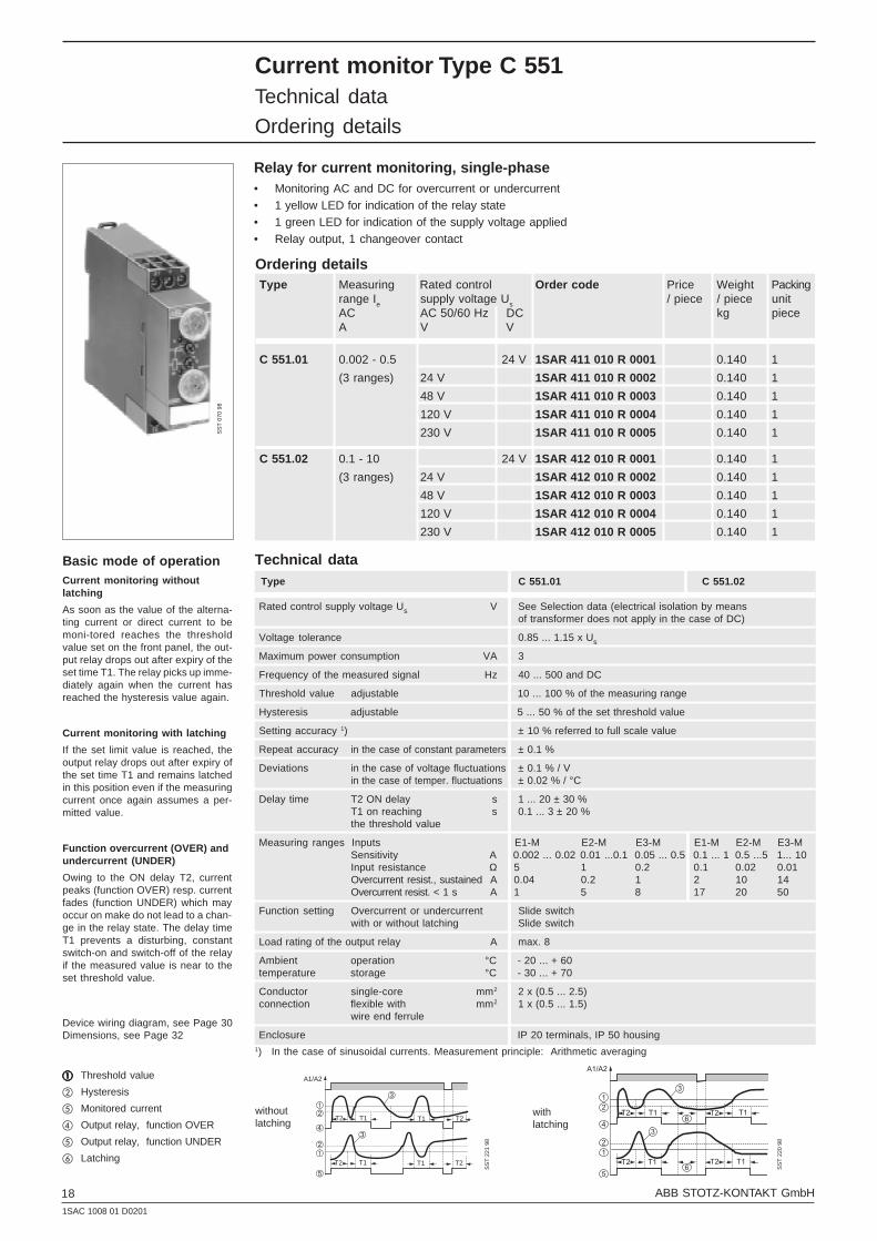
Relay for current monitoring, single-phase• Monitoring AC and DC for overcurrent or undercurrent• 1 yellow LED for indication of the relay state• 1 green LED for indication of the supply voltage applied• Relay output, 1 changeover contact
Technical data Type C 551.01 C 551.02
Rated control supply voltage Us V See Selection data (electrical isolation by meansof transformer does not apply in the case of DC)
Voltage tolerance 0.85 ... 1.15 x Us
Maximum power consumption VA 3
Frequency of the measured signal Hz 40 ... 500 and DC
Threshold value adjustable 10 ... 100 % of the measuring range
Hysteresis adjustable 5 ... 50 % of the set threshold value
Setting accuracy 1) ± 10 % referred to full scale value
Repeat accuracy in the case of constant parameters ± 0.1 %
Deviations in the case of voltage fluctuations ± 0.1 % / Vin the case of temper. fluctuations ± 0.02 % / °C
Delay time T2 ON delay s 1 ... 20 ± 30 %T1 on reaching s 0.1 ... 3 ± 20 %the threshold value
Measuring ranges Inputs E1-M E2-M E3-M E1-M E2-M E3-MSensitivity A 0.002 ... 0.02 0.01 ...0.1 0.05 ... 0.5 0.1 ... 1 0.5 ...5 1... 10Input resistance Ω 5 1 0.2 0.1 0.02 0.01Overcurrent resist., sustained A 0.04 0.2 1 2 10 14Overcurrent resist. < 1 s A 1 5 8 17 20 50
Function setting Overcurrent or undercurrent Slide switchwith or without latching Slide switch
Load rating of the output relay A max. 8
Ambient operation °C - 20 ... + 60temperature storage °C - 30 ... + 70
Conductor single-core mm2 2 x (0.5 ... 2.5)connection flexible with mm2 1 x (0.5 ... 1.5)
wire end ferrule
Enclosure IP 20 terminals, IP 50 housing1) In the case of sinusoidal currents. Measurement principle: Arithmetic averaging
Device wiring diagram, see Page 30Dimensions, see Page 32
Basic mode of operationCurrent monitoring withoutlatching
As soon as the value of the alterna-ting current or direct current to bemoni-tored reaches the thresholdvalue set on the front panel, the out-put relay drops out after expiry of theset time T1. The relay picks up imme-diately again when the current hasreached the hysteresis value again.
Current monitoring with latching
If the set limit value is reached, theoutput relay drops out after expiry ofthe set time T1 and remains latchedin this position even if the measuringcurrent once again assumes a per-mitted value.
Function overcurrent (OVER) andundercurrent (UNDER)
Owing to the ON delay T2, currentpeaks (function OVER) resp. currentfades (function UNDER) which mayoccur on make do not lead to a chan-ge in the relay state. The delay timeT1 prevents a disturbing, constantswitch-on and switch-off of the relayif the measured value is near to theset threshold value.
aaaaa Threshold value
b Hysteresis
e Monitored current
d Output relay, function OVER
e Output relay, function UNDER
f Latching
SS
T 0
70 9
8
withoutlatching
withlatching
SS
T 2
21 9
8
NSK-7994a
T1
A1/A2
T1 T2T2
T1 T1 T2T2
ÀÁ
ÂÃ
Ä
ÀÁ
Â
SS
T 2
20 9
8
NSK-7993
T1
A1/A2
T2 T1T2
T1T2 T1T2
1
2
4
2
1
5
3
3
6
6
Ordering detailsType Measuring Rated control Order code Price Weight Packing
range Ie supply voltage Us / piece / piece unitAC AC 50/60 Hz DC kg pieceA V V
C 551.01 0.002 - 0.5 24 V 1SAR 411 010 R 0001 0.140 1
(3 ranges) 24 V 1SAR 411 010 R 0002 0.140 1
48 V 1SAR 411 010 R 0003 0.140 1
120 V 1SAR 411 010 R 0004 0.140 1
230 V 1SAR 411 010 R 0005 0.140 1
C 551.02 0.1 - 10 24 V 1SAR 412 010 R 0001 0.140 1
(3 ranges) 24 V 1SAR 412 010 R 0002 0.140 1
48 V 1SAR 412 010 R 0003 0.140 1
120 V 1SAR 412 010 R 0004 0.140 1
230 V 1SAR 412 010 R 0005 0.140 1

19ABB STOTZ-KONTAKT GmbH1SAC 1008 01 D0201
Voltage monitor Type C 552Technical data
Ordering details
Relay for voltage monitoring, single-phase• Monitoring for overvoltage or undervoltage
• with or without latching
• 1 yellow LED for indication of the relay state; blinks during the operating time
• 1 green LED for indication of the control voltage applied
• Relay output, 1 changeover contact
Technical data
Type C 552.01 C 552.02
Rated control supply voltage Us V See Selection data (electrical isolation by means of transformerdoes not apply in the case of 24 V DC)
Voltage tolerance 0.85 ... 1.15 x Us
Maximum power consumption VA 3
Frequency of the measured signal Hz 40 ... 500 and DC
Threshold value Adjustable from 1 to 100 % of the measuring range
Hysteresis Adjustable from 5 to 50 % of the set threshold value
Setting accuracy ± 10 % referred to full scale value
Delay time on reaching the s adjustable 0.1 ... 3threshold value
Measuring ranges Inputs E1-M E2-M E3-M E1-M E2-M E3-M
Sensitivity V 0.2 ... 2 1 ... 10 6 ... 60 10 ... 100 30 ... 300 60 ... 600Input resistance kΩ 2 kΩ 10 kΩ 60 kΩ 100 300 600Overvoltage resistance V 200 350 650
Function setting Overvoltage or undervoltage Slide switchwith or without latching Slide switch
Load rating of Rated operating current A max. 8the output relay le/AC-15, 120 V
Ambient operation °C - 20 ... + 60temperature storage °C - 30 ... + 70
Conductor single-core mm2 2 x (0.5 ... 2.5)connection flexible with mm2 1 x (0.5 ... 1.5)
wire end ferrule
Enclosure IP 20 terminals, IP 50 housing
Device wiring diagram, see Page 30Dimensions, see Page 32
Basic mode of operationVoltage monitoring withoutlatching
As soon as the measuring-circuitvoltage reaches the set thresholdvalue, the output relay changes itscircuit state after expiry of the settime T1. It returns immediately to theoriginal state when the measuring-circuit voltage rea-ches the sethysteresis value.
Voltage monitoring with latching
If the set threshold value is rea-ched,the output relay changes its circuitstate after expiry of the set time T1and remains latched in this positioneven if the mea-suring-circuit voltageonce again assumes a permittedvalue.
a Threshold value
b Hysteresis
c Monitored voltage
d Output relay, function OVER
e Output relay, function UNDER
f Latching
SS
T 0
67 9
8
withoutlatching
withlatching
T1
T1
A1/A2
ÀÁ
ÂÃ
Ä
ÀÁ
Â
NSK-7990
SS
T 2
17 9
8
NSK-7991
T1
T1
A1/A2
ÀÁ
ÂÃ
ÄÅ
ÀÁ
Å
Â
SS
T 2
18 9
8
Ordering details
Type Measuring Rated control Order code Price / Weight / Packingrange Ue supply voltage Us
AC AC 50/60 Hz DC piece piece unitV V V kg piece
C 552.01 0.2 - 60 24 V 1SAR 421 010 R 0001 0.120 1
24 V 1SAR 421 010 R 0002 0.120 1
120 V 1SAR 421 010 R 0004 0.120 1
230 V 1SAR 421 010 R 0005 0.120 1
C 552.02 10 - 600 24 V 1SAR 422 010 R 0001 0.120 1
24 V 1SAR 422 010 R 0002 0.120 1
120 V 1SAR 422 010 R 0004 0.120 1
230 V 1SAR 422 010 R 0005 0.120 1

201SAC 1008 01 D0201
ABB STOTZ-KONTAKT GmbH
Voltage monitor with 2 limit values Type C 553Technical data
Ordering details
Relay for voltage monitoring, single-phase• Monitoring for overvoltage and undervoltage
• 1 yellow LED for indication of the relay state
• 1 green LED for indication of the control voltage applied
• Relay output, 1 changeover contact
Technical data
Rated control supply voltage Us V See evaluation data (with reverse voltage protection)
Voltage tolerance See evaluation data
Max. power consumption VA 3.5
Frequency of the measured signal/power system Hz 50/60 and DC
Threshold value Absolute scale within the measuring range
Hysteresis Fixed 5 % of the set threshold value
Setting accuracy ± 10 % referred to full scale value
Delay time on reaching the threshold value s adjustable 0.1 ... 3
Measuring ranges Inputs A1-A2
Sensitivity V See selection data, measuring range of versionInput resistance kΩ -
Overvoltage strength V See selection data, upper valueof the rated control supply voltage
Load rating of Rated operating current A max. 8the output relay Ie/AC-15, 120 V
Ambient operation °C - 20 ... + 60temperature storage °C - 30 ... + 70
Conductor- single-core mm2 2 x (0.5 ... 2.5)connection flexible with wire end ferrule mm2 1 x (0.5 ... 1.5)
Enclosure IP 20 terminals, IP 50 housing
Basic mode of operationRelay C 553 monitors a voltage corre-sponding to its own control supplyvoltage. As soon as the monitoredvoltage value leaves the set range,the output relay drops out after theset time has elapsed.
Device wire diagram, see Page 30
Dimensions, see Page 32
b Hysteresis
e Monitored voltage
g Upper threshold value
h Lower threshold value
i Output relay
SS
T 0
69 9
8
NSK-7992a
T1 T1
Ç
Æ
È
ÁÂ
SS
T 2
19 9
8
Ordering detailsType Measuring range = Rated control Order code Price / Weight / Packing
supply voltageUe piece piece unitV kg piece
C 553 AC/DC 20-80 1SAR 425 010 R 0008 0.150 1
AC/DC 65-260 1SAR 425 010 R 0009 0.150 1

21ABB STOTZ-KONTAKT GmbH1SAC 1008 01 D0201
Phase monitor Type C 554Technical data
Ordering details
Relay for phase monitoring, three-phase• Monitoring phase failures and phase sequence
• 1 yellow LED for indication of the relay state (OK state)
• Relay output, 2 changeover contacts
Technical data
Rated control supply voltage Us V 3 x 230-400, the monitored power systemsimultaneously serves to power the relay
Voltage tolerance V 3 x 200 ... 460
Power consumption at 200 V VA 5at 400 V VA 20at 460 V VA 25
Frequency of the measured power system Hz 50/60
Delay time T1 with correct phase sequence ms max. 200
T2 in the case of phase failure ms approx. 300
Load rating of the output relay
Making/breaking capacity AC VA max. 2000DC W max. 80
Switched current AC/DC A max. 8
Switched voltage AC/DC V max. 250
Disruptive strength in accordance with IEC 255-5 2.5 kV/1 min
Electrical service life operations 105 at maximum making/breaking capacity
Mechanical service life operations 2 x 10⁵
Ambient operation °C - 20 ... + 60temperature storage °C - 30 ... + 70
Conductor- single-core mm2 2 x (0.5 ... 2.5)connection flexible with wire end ferrule mm2 1 x (0.5 ... 1.5)
Enclosure IP 20 terminals, IP 50 housing
Basic mode of operationRelays for phase monitoring monitorthe phase sequence and failure ofone of the three phases. No settingsare required during operation. If thephase sequence is correct and noneof the three phases has failed, theoutput relay picks up after the delaytime T1 and the LED lights. In theevent of a phase failure or fault, theoutput relay drops out after the delaytime T2 has elapsed and the LEDgoes out.
If a phase sequence error occurs onswitch-on of the voltage, the relaydoes not pick up.
Note:
Relay C 554 is not protected againstreverse voltage. If there is a risk ofenergy recovery from a motor in theevent of phase failure, relay C 557with monitoring of phase asymmetrycan be used.
Device wiring diagram, see Page 30
Dimensions, see Page 32
a Output relay
T1: Delay on pick-up 200 msT2: Delay on drop-out, max. 300 ms
SS
T 0
68 9
8
NSK-7999aU
L2
L3
T1
T2
L3
L2
L1
T2T1
1 SS
T 2
25 9
8
Ordering details
Type Measuring Rated control Order code Price / Weight / Packingrange Ue supply voltage Us
AC 50/60 Hz AC 50/60 Hz piece piece unitV V kg piece
C 554 3 x 200-460 3 x 200-460 1SAR 430 010 R 0010 0.120 1
221SAC 1008 01 D0201
ABB STOTZ-KONTAKT GmbH
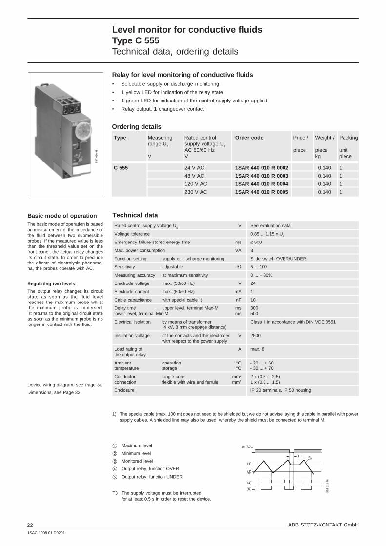
Level monitor for conductive fluidsType C 555Technical data, ordering details
Relay for level monitoring of conductive fluids• Selectable supply or discharge monitoring
• 1 yellow LED for indication of the relay state
• 1 green LED for indication of the control supply voltage applied
• Relay output, 1 changeover contact
Technical data
Rated control supply voltage Us V See evaluation data
Voltage tolerance 0.85 ... 1.15 x Us
Emergency failure stored energy time ms ≤ 500
Max. power consumption VA 3
Function setting supply or discharge monitoring Slide switch OVER/UNDER
Sensitivity adjustable kh 5 ... 100
Measuring accuracy at maximum sensitivity 0 ... + 30%
Electrode voltage max. (50/60 Hz) V 24
Electrode current max. (50/60 Hz) mA 1
Cable capacitance with special cable 1) nF 10
Delay time upper level, terminal Max-M ms 300lower level, terminal Min-M ms 500
Electrical isolation by means of transformer Class II in accordance with DIN VDE 0551(4 kV, 8 mm creepage distance)
Insulation voltage of the contacts and the electrodes V 2500with respect to the power supply
Load rating of A max. 8the output relay
Ambient operation °C - 20 ... + 60temperature storage °C - 30 ... + 70
Conductor- single-core mm2 2 x (0.5 ... 2.5)connection flexible with wire end ferrule mm2 1 x (0.5 ... 1.5)
Enclosure IP 20 terminals, IP 50 housing
Basic mode of operationThe basic mode of operation is basedon measurement of the impedance ofthe fluid between two submersibleprobes. If the measured value is lessthan the threshold value set on thefront panel, the actual relay changesits circuit state. In order to precludethe effects of electrolysis phenome-na, the probes operate with AC.
Regulating two levels
The output relay changes its circuitstate as soon as the fluid levelreaches the maximum probe whilstthe minimum probe is immersed. It returns to the original circuit stateas soon as the minimum probe is nolonger in contact with the fluid.
Device wiring diagram, see Page 30
Dimensions, see Page 32
a Maximum level
b Minimum level
c Monitored level
d Output relay, function OVER
e Output relay, function UNDER
T3 The supply voltage must be interruptedfor at least 0.5 s in order to reset the device.
1) The special cable (max. 100 m) does not need to be shielded but we do not advise laying this cable in parallel with powersupply cables. A shielded line may also be used, whereby the shield must be connected to terminal M.
SS
T 0
66 9
8
NSK-7995aA1/A2
T3
1
2
4
5
3
SS
T 2
22 9
8
Ordering details
Type Measuring Rated control Order code Price / Weight / Packingrange Ue supply voltage Us
AC 50/60 Hz piece piece unitV V kg piece
C 555 24 V AC 1SAR 440 010 R 0002 0.140 1
48 V AC 1SAR 440 010 R 0003 0.140 1
120 V AC 1SAR 440 010 R 0004 0.140 1
230 V AC 1SAR 440 010 R 0005 0.140 1

23ABB STOTZ-KONTAKT GmbH1SAC 1008 01 D0201
Technical dataLower threshold value 80-98% Un
Upper threshold value 102-120% Un
Electrical isolation by means of transformer
Power system monitoring 3 x 400 V AC
Frequency of the monitored power system 50/60 Hz
Hysteresis fixed, 4 % of the set threshold value
Indicating accuracy ±10% of the scale value
Repeat accuracy in the case of constant parameters ± 0.5%
Delay on transgression 0.1 s-10 s, 0 + 50%of the threshold values
Output relay (in accordance with AC-1, resistive load) 2 AgCdO changeover contacts, 8 A AC
Voltage monitor between phases and neutral conductorin three-phase power systems, Type C 556.01Technical data, ordering details
• Measures its own supply voltage
• Relay for monitoring overvoltages andundervoltages
• Lower and upper threshold value separatelysettable
• Detection of phase failures
• Does not respond to incorrect phase se-quence
• Indication of overvoltage, undervoltage andrelay status via 3 LEDs.
• Delay if the threshold value is overshot orundershot can be set on the front panelbetween 0.1 and 10 s.
2 output relays:
1 changeover contact 8 A: Overvoltage
1 changeover contact 8 A: Undervoltage
Overall width: 45 mm
Relay for voltage monitoring in three-phase power systemswith neutral conductor
Device wiring diagram, see Page 31Dimensions; see Page 32
SS
T 0
63 9
8
a Threshold value Umax
b Hysteresis
c Threshold value Umin
d Output relay Umin
e Output relay Umax
Basic mode of operationThe output relay picks up as soon asthe values of the three star voltages ofthe phases with respect to the neutralconductor lie between the lower andupper threshold value. The thresholdvalues are set separately via twopotentiometers on the device frontpanel.
If the value of one voltage is outside ofthis range, the corresponding outputrelay drops out after a delay time T1or T2 which can be set on the frontpanel has elapsed. A fixed hysteresisof 3 % prevents continuous switch-on and switch-off of the output relayif the measuring-circuit voltage is nearto a set threshold value.
The phase sequence and phase asym-metry are not monitored. DeviceC 556.01 also responds to failure ofthe neutral conductor. NSK-8353
L1/L2
T1
T2
L2/L3L1/L3
12
2
3
4
5
U
SS
T 2
29 9
8
Ordering details
Type Supply voltage Uc Order code Price / Weight / Packingpiece piece unit
V kg piece
C 556.01 400 V AC 1SAR 450 010 R 0006 0.300 1

241SAC 1008 01 D0201
ABB STOTZ-KONTAKT GmbH
Technical data
Lower threshold value 80 - 98% Un
Upper threshold value 102 - 120% Un
Electrical isolation by means of transformer
Power system monitoring 3 x 400 V AC + N
Frequency of the monitored power system 50/60 Hz
Hysteresis fixed, 4 % of the set threshold value
Indicating accuracy ±10% of the scale value
Repeat accuracy in the case of constant parameters ± 0.5%
Delay on transgression 0.1 s-10 s, 0 + 50%of the threshold values
Output relay (in a ccordance with AC-1, resistive load) 2 AgCdO changeover contacts, 8 A AC
Voltage monitor for three-phase power systemsType C 556.02Technical data, ordering details
• Measures its own supply voltage
• Relay for monitoring overvoltages and under-voltages
• Lower and upper threshold value separatelysettable
• Detection of phase failures
• Does not respond to incorrect phase sequence
• Indication of overvoltage, undervoltage andstatus via 3 LEDs.
• Delay if the threshold value is overshot orundershot can be set on the front panelbetween 0.1 and 10 s.
2 output relays:
1 changeover contact 8 A: Overvoltage
1 changeover contact 8 A: Undervoltage
Overall width: 45 mm
Relay for voltage monitoring in three-phase power systemswith neutral conductor
Device wiring diagram, see Page 31Dimensions, see Page 32
Basic mode of operationThe output relay picks up as soon asthe values of the three phase-to-phase voltages lie between thelower and upper threshold value. Thethreshold values are set separatelyvia two potentiometers on the devicefront panel.
If the value of one voltage is outside ofthis range, the corresponding outputrelay drops out after a delay time T1or T2 which can be set on the frontpanel has elapsed. A fixed hysteresisof 3 % prevents continuous switch-on and switch-off of the output relayif the measuring-circuit voltage is nearto a set threshold value.
The phase sequence and phase asym-metry are not monitored.
SS
T 0
64 9
8
a Threshold value Umax
b Hysteresis
c Threshold value Umin
d Output relay Umin
e Output relay Umax
NSK-8353
L1/L2
T1
T2
L2/L3L1/L3
12
2
3
4
5
U
SS
T 2
29 9
8
Ordering details
Type Supply voltage Uc Order code Price / Weight / Packingpiece piece unit
V kg piece
C 556.02 400 V AC 1SAR 451 010 R 0006 0.300 1
25ABB STOTZ-KONTAKT GmbH1SAC 1008 01 D0201
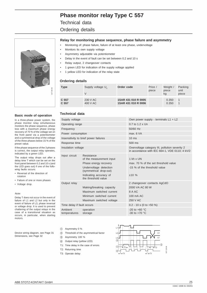
Phase monitor relay Type C 557Technical data
Ordering details
Relay for monitoring phase sequence, phase failure and asymmetry• Monitoring of: phase failure, failure of at least one phase, undervoltage
• Monitors its own supply voltage
• Asymmetry adjustable via potentiometer
• Delay in the event of fault can be set between 0.2 and 10 s
• Relay output, 2 changeover contacts
• 1 green LED for indication of the supply voltage applied
• 1 yellow LED for indication of the relay state
Technical data
Supply voltage Own power supply - terminals L1 + L2
Operating range 0.7 to 1.2 x Un
Frequency 50/60 Hz
Power consumption max. 6 VA
Insensitivity to brief power failures 10 ms
Response time 500 ms
Insulation voltage Overvoltage category III, pollution severity 2in accordance with IEC 664-1, VDE 0110; 4 kV/2
Input circuit Resistanceof the measurement input 1 kh x UN
Phase energy recovery max. 70 % of the set threshold value
Undervoltage detection -15 % of the threshold value(symmetrical drop-out)
Indicating accuracy of ±10 %the threshold value
Output relay 2 changeover contacts AgCdO
Making/breaking capacity 2000 VA AC 80 W
Maximum switched current 8 A AC
Minimum switched current 100 mA AC
Maximum switched voltage 250 V AC
Time delay if fault occurs 0.2 - 10 s (0 to +50 %)
Ambient operation -20 to +60 °Ctemperatures storage -30 to +70 °C
Basic mode of operationIn a three-phase power system, thephase monitor relay simultaneousmonitors the phase sequence, phaseloss with a maximum phase energyrecovery of 70 % of the voltage set onthe front panel via a potentiometerand a symmetrical drop of the voltageof the three phases below 15 % of thepreset value.
If the phase sequence of the 3 phasesis correct, the output relay operates,indicated by a green LED.
The output relay drops out after adelay time T which can be set on thefront panel between 0.2 and 10 s (andthe LED goes out) if one of the follo-wing faults occurs:
• Reversal of the direction ofrotation
• Failure of one or more phases
• Voltage drop.
Note:
Delay T does not occur in the event offailure of L1 and L2 but only in theevent of failure of L3, phase reversalor voltage drop. It is used to preventchattering of the output relays in thecase of a transitional situation asoccurs, in particular, when startingmotors.
SS
T 0
65 9
8
Device wiring diagram, see Page 31Dimensions, see Page 32
NSK-8352
L3
L2
L1
T2
T3
T1
T3
L2
L3
12
3
4
SS
T 2
28 9
8
a Asymmetry 0 %
b Threshold of the asymmetrical factor
c Asymmetry 100 %
d Output relay (yellow LED)
T1: Time delay in the case of errors
T2: Returning time
T3: Operate delay
Ordering details
Type Supply voltage Uc Order code Price / Weight / Packingpiece piece unit
V kg piece
C 557 230 V AC 1SAR 431 010 R 0005 0.350 1C 557 400 V AC 1SAR 431 010 R 0006 0.350 1
261SAC 1008 01 D0201
ABB STOTZ-KONTAKT GmbH
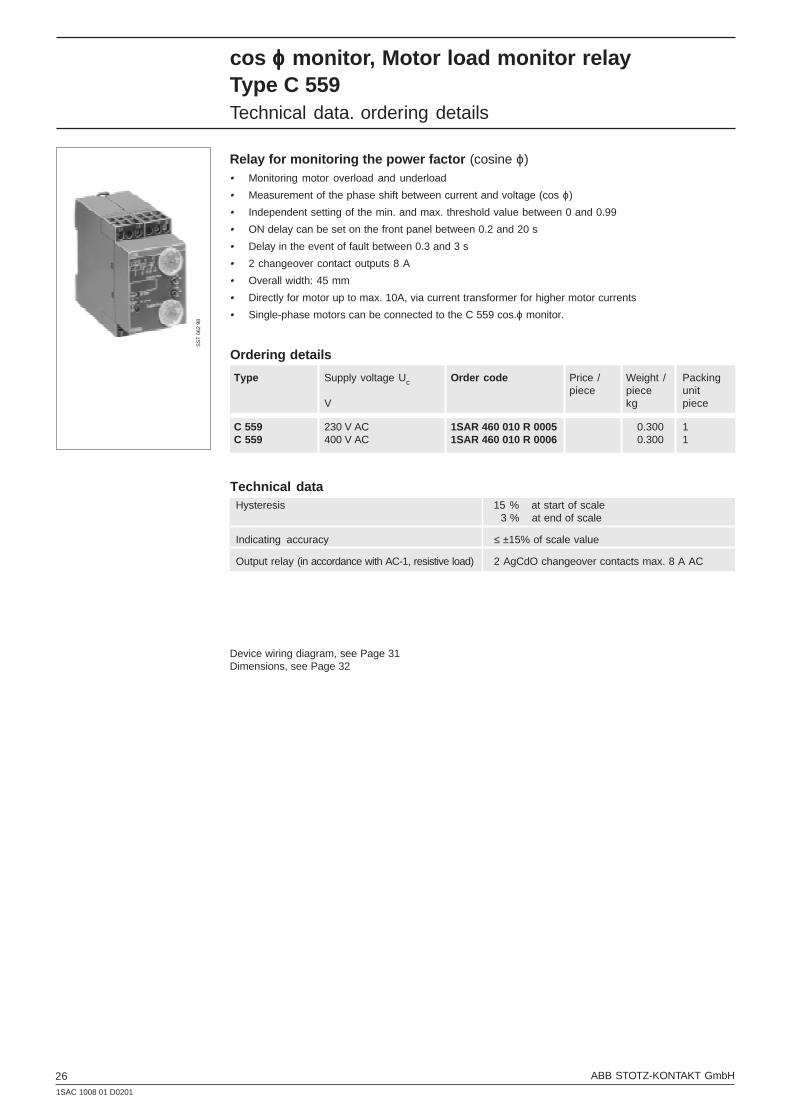
cos ϕϕϕϕϕ monitor, Motor load monitor relayType C 559Technical data. ordering details
Relay for monitoring the power factor (cosine ϕ)• Monitoring motor overload and underload
• Measurement of the phase shift between current and voltage (cos ϕ)
• Independent setting of the min. and max. threshold value between 0 and 0.99
• ON delay can be set on the front panel between 0.2 and 20 s
• Delay in the event of fault between 0.3 and 3 s
• 2 changeover contact outputs 8 A
• Overall width: 45 mm
• Directly for motor up to max. 10A, via current transformer for higher motor currents
• Single-phase motors can be connected to the C 559 cos.ϕ monitor.
Technical dataHysteresis 15 % at start of scale
3 % at end of scale
Indicating accuracy ≤ ±15% of scale value
Output relay (in accordance with AC-1, resistive load) 2 AgCdO changeover contacts max. 8 A AC
Device wiring diagram, see Page 31Dimensions, see Page 32
SS
T 0
62 9
8
Ordering details
Type Supply voltage Uc Order code Price / Weight / Packingpiece piece unit
V kg piece
C 559 230 V AC 1SAR 460 010 R 0005 0.300 1C 559 400 V AC 1SAR 460 010 R 0006 0.300 1

27ABB STOTZ-KONTAKT GmbH1SAC 1008 01 D0201
Speed Monitor Type C 580Technical data
Ordering details
Princip of FunctionThis relay monitors stillstand and un-der speed levels.
By system start, a monitoring delaytime from 0.3 ... 30 sec is adjustable.For this delay time the measuringsignals are locked. The relay doesn’tact.
For more than 30 sec the externalcontact „S2“ is to be closed and canbe opened if the start has finished.In this way the customer can state aflexible delay time.
Customer can adjust a time between2 measured pulses.If the time tolerance is out of theadjusted range – the relay will switchby underlimit not by over limit. If thespeed level comes in the normal ran-ge again the relay will go back innormal position.
By using a measuring voltage, max.30 V the relay will give also a contactby under limit.
Measuring inputs are:
• Puse signal of 3-contact
• Namur pulse signal
• Potential free contact
• Voltage signal
SS
T 0
66 9
8
Ordering details
Type Supply voltage Uc Order code Price / Weight / Packingpiece piece unit
V kg peice
C 580 24 V AC 1SAR 480 010 R 0002 0.255 1120 V AC 1SAR 480 010 R 0004 0.255 1230 V AC 1SAR 480 010 R 0005 0.255 124 V DC 1SAR 480 010 R 0001 0.255 1
Relay C580 for monitoring speed levels, stillstand, transport failures• 1 LED for power indication
• 1 LED for switching
• 1 change over contact
without locking function
Hysteresis
indicated RPM
output relay
blocking
delay
min. 200 mswith locking
U
S 2
output relay
Hysteresis
indicated RPM
Device wiring diagram, see Page 31Dimensions, see Page 32
blocking
delayblocking
delay
Technical dataPower supply 24 DC, 24 V, 120, 230 VAC, 50/60 Hz
Tolerance of voltage ± 15 %
Power consumption 3.5 VA AC / 1W DC
Allowed voltage break 10 ms
Input Sensor 24 V PNP (max. 50 mA)Namur-sensor 8.2 V at 1 kOhmPotential free contactVoltage 0 - 30 V
1-signal 4.5 - 30 V
0-signal 0 - 1 V
Switching frequency 200 Hz
Min. pulse length 5 ms
Pulse-Pause 5 ms : 5ms
Delay times 0.1 - 10 sec.
Hysteresis 5 %
Accuracy for indication 10 % of full scale
Repeat accuracy ± 15 %
Rest time Min. 200 ms / 100 ms for S2
Start delay 0.3 - 30 sec.
Output 1 change over contact
Min. load 100 mA
Max. AC load 8 A, 100 V, 2000 VA
Max. DC load 8 A, 100 V, 80 W
Max. switching frequency 360 switches per h
Electrical life time AC12: 100000 switchesAC15: 6000 switches at cos phi = 0.3DC13: 6000 switches L/R=300 ms
Operating temperature -20 ... +60 °C
Storage temperature -30 ... +70 °C

281SAC 1008 01 D0201
ABB STOTZ-KONTAKT GmbH
Zero speed monitor Type C 581Technical data
Ordering details
Relay C581 for monitoring stillstand of 1- or 3-phase motors• 1 LED for power indication
• 1 LED for switching
• 1 NO, 1 NC safety signal outputs, positively driven
• Safety category 4
Technical dataPower supply 24 V DC, rest max. 10 %, 24 V AC, 50/60 Hz
Tolerance of voltage ± 15 %
Power consumption 1.6 VA AC / 2 W DC
Allowed voltage break 10 ms
Input Chanel 1: 20 ... 500 mV ± 15%Chanel 1: 20 ... 500 mV ± 15%
Difference of synchronisation < 3 sec.
Hysteresis 40 %
Accuracy for indication 10 % of full scale
Repeat accuracy ± 0.5 %
Output 1 NO and 1 NC potential free
Max. AC load 6.8 A, 1500 VA
Max. switching voltage 440 V AC
Electrical life time 100000 switches at 1500 VA
Operating temperature -20 ... +50 °C
Storage temperature -30 ... +70 °C
Princip of FunctionThis relay monitors stillstands depen-ding on rest voltages in the powerline.
Normaly the motor gets a power sup-ply voltage of about 400 V or more.By stillstand the motor voltage gets to„0“. If there is a small moving themotor will have a rest voltage. Thisrest voltage is to be measured.
By stillstand in a tolerance range therelay give a contact- neccesary formachine stops where people are onlyallowed to open the door if the motordoesn’t move and must be in an ab-solutely stop position. This devicehas safety category 4.
Inputs:
Voltages for measuring signals,redundant:
Chanel 1: 20 mV ... 500 mV
Chanel 2: 20 mV ... 500 mV
Ordering details
Type Supply voltage Uc Order code Price / Weigth / Packingpiece piece unit
V kg piece
C 581 24 V AC/DC 1SAR 481 030 R 0011 0.410 1
29ABB STOTZ-KONTAKT GmbH1SAC 1008 01 D0201
Zero speed monitor Type C 581Technical data
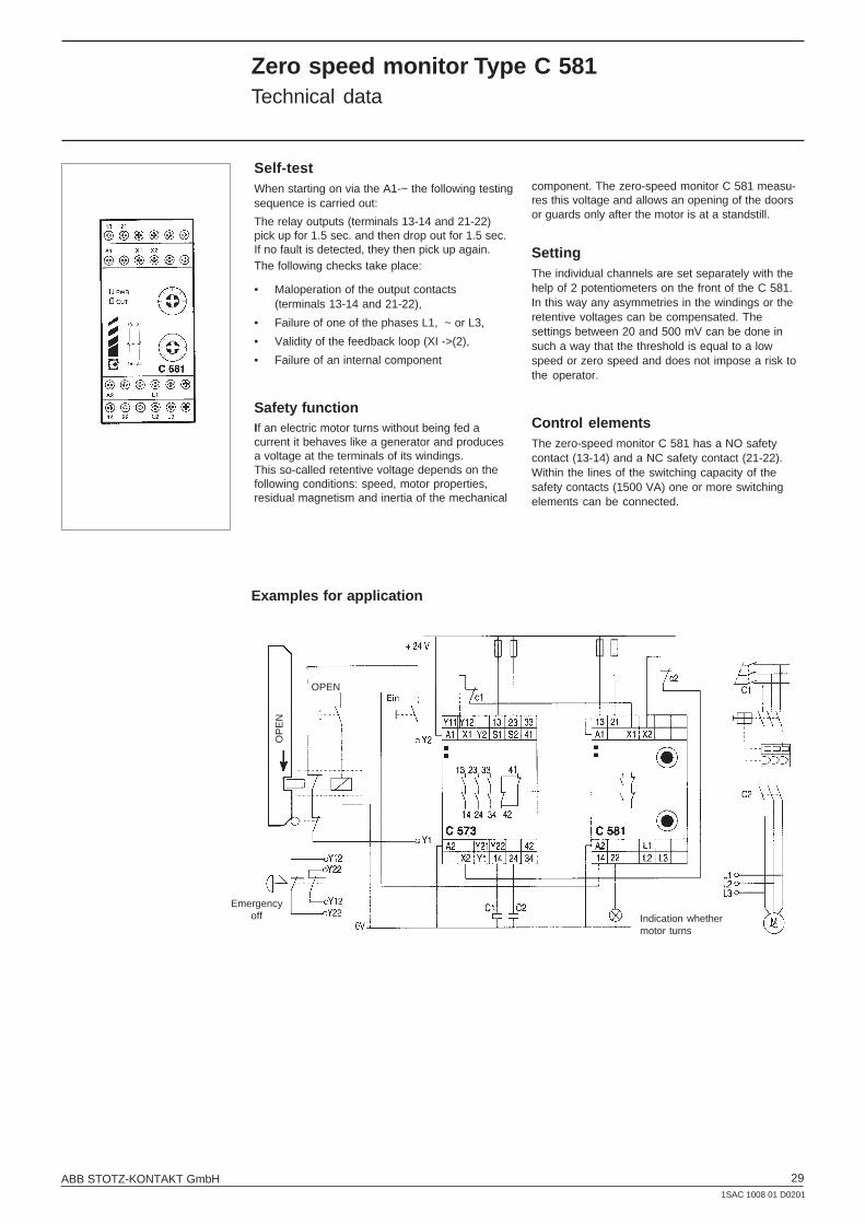
Self-testWhen starting on via the A1-~ the following testingsequence is carried out:
The relay outputs (terminals 13-14 and 21-22)pick up for 1.5 sec. and then drop out for 1.5 sec.If no fault is detected, they then pick up again.The following checks take place:
• Maloperation of the output contacts(terminals 13-14 and 21-22),
• Failure of one of the phases L1, ~ or L3,
• Validity of the feedback loop (XI ->(2),
• Failure of an internal component
Safety functionIf an electric motor turns without being fed acurrent it behaves like a generator and producesa voltage at the terminals of its windings.This so-called retentive voltage depends on thefollowing conditions: speed, motor properties,residual magnetism and inertia of the mechanical
component. The zero-speed monitor C 581 measu-res this voltage and allows an opening of the doorsor guards only after the motor is at a standstill.
SettingThe individual channels are set separately with thehelp of 2 potentiometers on the front of the C 581.In this way any asymmetries in the windings or theretentive voltages can be compensated. Thesettings between 20 and 500 mV can be done insuch a way that the threshold is equal to a lowspeed or zero speed and does not impose a risk tothe operator.
Control elementsThe zero-speed monitor C 581 has a NO safetycontact (13-14) and a NC safety contact (21-22).Within the lines of the switching capacity of thesafety contacts (1500 VA) one or more switchingelements can be connected.
Examples for application
OP
EN
OPEN
Emergencyoff Indication whether
motor turns

301SAC 1008 01 D0201
ABB STOTZ-KONTAKT GmbH
Voltage monitor C 551.01 / C 551.02
C 552.01 / C 552.02
Voltage monitor C 553
Phase monitor C 554
Monitoring relays C 55xWiring diagrams
Connection diagrams
Level monitor C 555
Filling level monitoring Up Pump-off monitoring Down
a.c. voltage or d.c. voltageto be monitored
Supply voltageto be monitored
(1) Disconnector(2) Contactor
Terminal assignmentTerminals L1 – L2 – L3: three-phase power system to be monitored
11 – 12 – 14: output relays
Input
Start
Output
Stop
Start
Output
31ABB STOTZ-KONTAKT GmbH1SAC 1008 01 D0201
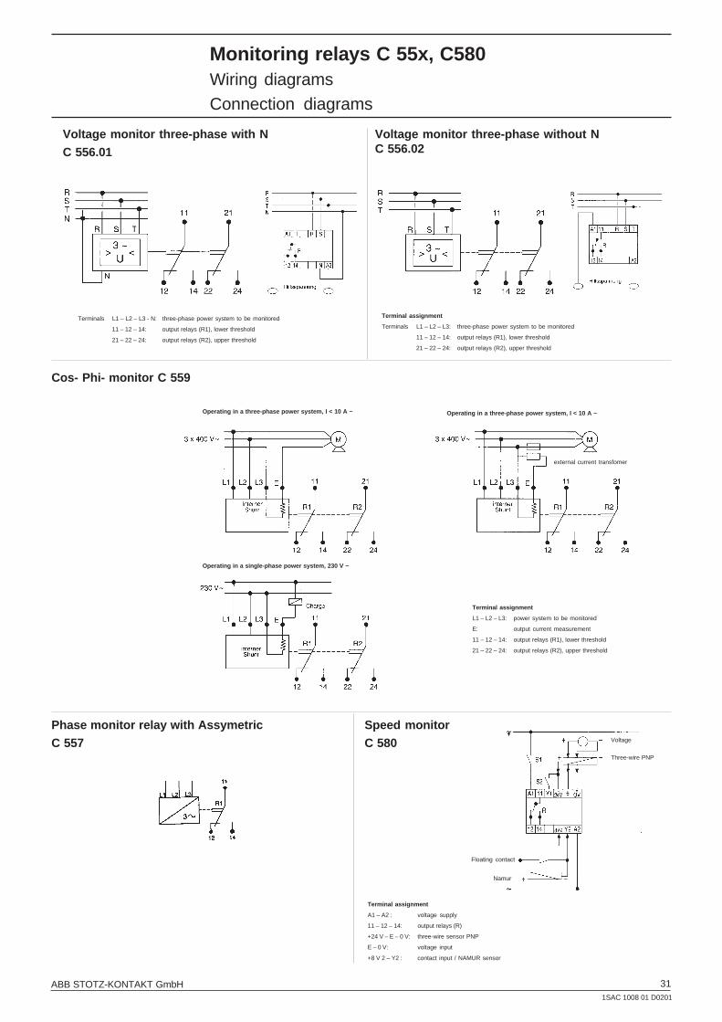
Monitoring relays C 55x, C580Wiring diagrams
Connection diagrams
Voltage monitor three-phase with NC 556.01
Voltage monitor three-phase without NC 556.02
Speed monitorC 580
Cos- Phi- monitor C 559
Phase monitor relay with AssymetricC 557
Terminals L1 – L2 – L3 - N: three-phase power system to be monitored
11 – 12 – 14: output relays (R1), lower threshold
21 – 22 – 24: output relays (R2), upper threshold
Terminal assignment
Terminals L1 – L2 – L3: three-phase power system to be monitored
11 – 12 – 14: output relays (R1), lower threshold
21 – 22 – 24: output relays (R2), upper threshold
Operating in a three-phase power system, I < 10 A ~
Operating in a single-phase power system, 230 V ~
Operating in a three-phase power system, I < 10 A ~
external current transfomer
Terminal assignment
L1 – L2 – L3: power system to be monitored
E: output current measurement
11 – 12 – 14: output relays (R1), lower threshold
21 – 22 – 24: output relays (R2), upper threshold
Voltage
Three-wire PNP
Floating contact
Namur
Terminal assignment
A1 – A2 : voltage supply
11 – 12 – 14: output relays (R)
+24 V – E – 0 V: three-wire sensor PNP
E – 0 V: voltage input
+8 V 2 – Y2 : contact input / NAMUR sensor

321SAC 1008 01 D0201
ABB STOTZ-KONTAKT GmbH
Electronic Monitor relayDimension diagrams
78,5
89,7
99,3
22,5
4,2
57
5
3,5
100
72
57
7723
100
78,5
45
3,5
Dimensions in mmC 551, C 552, C 553 C 554, C 555
C 556.01, C 556.02, C 557, C 559, C 580
C 558

33ABB STOTZ-KONTAKT GmbH1SAC 1008 01 D0201
Insulation monitoring deviceand Earth-leakage monitor Type C 558.01Technical data, ordering details
Insulation monitoring device for IT AC systems with DC componentsand for IT DC systems
• Industrial control systems
• Automotive industry
• Machine control systems
• Control systems in power plants and powersupply companies
• Computer systems
• mobile generators
• Elevator controls
• Lighting and battery systems
Application in modern control voltage systems
Product descriptionModern control voltage systemsfrequently contain DC componentsand high system leakage capaci-tances due to interference suppressi-on arrangements.
These circumstances must be takeninto account when selecting the insu-lation monitoring device.
The C558.01 guarantees reliableinsulation monitoring of modernsystems. Pure AC systems, pure DCsystems as well as AC/DC systemscan be monitored.
Device characteristics• Insulation monitoring of IT AC, DC and AC/DC
systems
• Voltage range up to AC 300 V and DC 290 V
• automatic adaptation to the given systemconditions
• Connection monitoring
• adjustable response value 1 ... 200 kΩ
CE = System leakage capacitanceRF = Insulation faultt = Measuring time
Measuring time
• Power On and alarm LED with fault localization
• combined test and reset button
• two change-over contacts
• N/O or N/C operation, selectable
• fault memory, selectable
Fault indications
Indication Alarm AlarmLED relay+ -
AC fault x x x
DC fault L+ x x
DC fault L- x x
Interruption o o x /KE resp. L1/L2
o = flashingx = continuous indication
Ordering details
Type Supply voltage Uc Order code Price / Weight / Packingpiece piece unit
V kg piece
C 558.01 230 V AC 1SAR 470 020 R 0005 0.350 1C 558.01 90-132 V AC 1SAR 470 020 R 0004 0.350 1
Response value and measuring circuit
Type Response Response Measuring Measur. Internal System voltagevalue Ran time1) voltage current resistance2)
C 558.01 10-200 kΩ 5 s 13 V 0.11mA 120/94 kΩ DC and AC0 - 300 V 15 - 400 Hz
0 - 300 V
1) Response times at 1 µF system leakage capacitance.2) DC internal resistance/Impedance
Measuring principle
The C 558.01 operates with a variant of a pulse measuring principle. This measuring principle ensuresreliable monitoring of modern control voltage systems. The frequency range of the system to be monitoredmay extend from 15 ... 400 Hz.
Wiring diagrams and dimensions diagrams see page 37
Standards
The C 558.01 complies with the standards DIN 57413 T8 / VDE 0413 T8, IEC 61557-8, EN 61557-8 andASTM F1669M-96.
When installing the device, the safety instuctions supplied with the equipment must be observed!
Certifications

341SAC 1008 01 D0201
ABB STOTZ-KONTAKT GmbH
Insulation monitoring deviceand Earth-leakage monitor Type C 558.02Technical data, ordering details
Insulation monitoring device for IT AC systems
• AC and 3 AC systems without DC compon-ents
• Motor drives without converters
• Building installation practice
• Simple machine drives
• Generating sets, mobile generators
• Power supply for public events
• Lighting systems
• Air cooling and air-conditioning systems
Application in classical power supply systems
Wiring diagrams and dimensions diagrams see page 37
Product descriptionThe classical power supply system isa pure AC system. It neither containsconverters nor DC components.
The system leakage capacitance isrelatively low, i.e. it usually is below1 µF, sometimes slightly above thisvalue.
The C558.02 can be used to monitorthese systems, up to 690 V.
For setting the response value, youcan choose from two response ran-ges, either 1 ... 20 kW or 10 ... 200 kW.
Measuring principleSuperimposed DC voltage with reversing stage.
StandardsThe C 558.02 complies with the standards DIN 57413 Bl.2 / VDE 0413 T2, IEC 61557-8, EN 61557-8 andASTM F1207-89.
When installing the device, the safety instruc tions supplied with the equipment must be observed!
Certifications
Device characteristics• Insulation monitoring device of AC and 3 AC
systems up to 690 V
• adjustable response value 1 h ... 200 kΩ• Power ON and alarm LED’s with fault localiza-
tion
• combined test and reset button
• Connection monitoring
• Alrm relay with two change-over contacts
Setting the adjustment range
Changing the setting range fromx1kΩ to x10kΩ, automatically chan-ges the indication of the kΩ valueson the LED bar graph indicator:
Setting range x1 k ΩΩΩΩΩMeter scale point x1 kΩ
Setting range x10 k ΩΩΩΩΩThe meter scale point has to bemultiplied by 10 kΩ
• N/O / N/C operation, selectable
• Fault memory, selectable
• LED indicator
• Sealable housing
• Connectable to an external meter
Ordering details
Type Supply voltage Uc Order code Price / Weight / Packingpiece piece unit
V kg piece
C 558.02 230 V AC 1SAR 471 020 R 0005 0.350 1C 558.02 90-132 V AC 1SAR 471 020 R 0004 0.350 1
Accessories (external k ΩΩΩΩΩ-Measuring instruments)
C 558.10 1SAR 477 000 R 0100 0.200 1
Response delay
Type *) Response time in the *) Response time in the Max. system leakagerange of 10...200 kΩ range of 1...20 kΩ capacitance
C 558.02 < 1 sec. < 3 sec. 20 µF
*) Response times acc. to IEC 61557-8 at RF=0,5xRan and at 1 µF system leakage capacitance.

35ABB STOTZ-KONTAKT GmbH1SAC 1008 01 D0201
Insulation monitoring deviceand Earth-leakage monitor Type C 558.03Technical data, ordering details
Insulation monitoring deviceC558.03 monitors the insulation resistance of an unearthed a.c. voltage or d.c. voltage system
Application in modern control voltage systems
Accessories (external k ΩΩΩΩΩ-Measuring instruments)
C 558.10 1SAR 477 000 R 0100 185,00 0.200 1
Product descriptionThe C 558.03 monitors the insulationresitance of IT systems (unearthedsystems) up to AC 690 V or DC 400 V.It can be universally used in a.c., d.c.or non-uniform power systems.
Interference suppression and capa-citances of up to 20 µF to earth whichare caused by lengthy supply lineshave no influence on the measure-ment.
The integrated AMP measuringmethod ensures the reliable insulati-on monitoring even in power systemswith fixed frequency converters (out-put and input frequency are static).
Response delay
Type *) Response time in the *) Response time in the Max. system leakagerange of 10...200 kΩ range of 1...20 kΩ capacitance
C 558.03 < 1 sec. < 3 sec. 20 µF
*) Response times acc. to IEC 61557-8 at RF=0,5xRan and at 1 µF system leakage capacitance.
Measuring principleSuperimposed DC voltage with reversing stage.
Standards
The C 558.03 complies with the standards DIN 57413 Bl.2 / VDE 0413 T2, IEC 61557-8, EN 61557-8andASTM F1207-89.
When installing the device, the safety instrucktions supplied with the equipment must be observed!
Certifications
Device characteristics• Insulation monitoring of IT-AC, DC and AC/DC
systems
• Connection monitoring
• Alarm or system fault indication selectable
• AMP measuring method (EP logon)
• Automatic adaptation to the power system
• Infinitely adjustable response value 2 to 50 or20 to 500 kΩ
• Power-on LED, alarm LED and kΩ runningpoint LED display
• Industrial control systems
• Automation systems
• Machine control systems
• Control systems for power stations and utilitycompanies
• Computer networks
• Mobile generators
• Lift control systems
• Lighting systems
• Combined test and reset key
• 2 pilot relays with 1 changeover contact each
• Open-circuit/N/C operation, selectable
• Fault memory, selectable
• Running point LED display
• Sealable housing VDE 0106 T 101
• Environmental conditions comply withEN 50155
Fault indications
Indication Alarm AlarmLEDs relay+ -
AC fault x x x
DC x x (L+)
DC x x (L-)
Interruption o o x L1/L2 resp. KE
o = flashingx = continuous indication
Wiring diagrams and dimensions diagrams see page 37
Ordering details
Type Supply Voltage Uc Order code Price / Weigh t/ Packingpiece piece Unit
V kg piece
C 558.03 230 V AC 1SAR 472 020 R 0005 0.350 1C 558.03 90-132 V AC 1SAR 472 020 R 0004 0.350 1

361SAC 1008 01 D0201
ABB STOTZ-KONTAKT GmbH
Insulation monitoring in IT-systemsElectrical safety for people and machine
Insulation resistance is a very important factor when the protective goals are being considered.
Insulation monitoring in IT-systemsInsulation monitoring device / Earth-leakagemonitor C 558.01, C 558.02, C 558.03
Electrical
• static overvoltage
• transient overvoltage
• frequency changes
• lightning
• overload
• voltage form
Mechanical
• shock, impact
• flaw, bend
• vibrations
• penetration of foreign bodies, such as nails
The IT system with additional equipotential bonding and insulation monitoring equipment
Environmental
• climate
• moisture, temperature
• chemical influences
• pollution, dust, oil
• agressive exhaust air, fumes
• ageing
Other effects
• animals (such as biting by rodents)
• plants
• incorrect connections
Insulationmonitoring device
additional equipotentialbonding
The IT system is supplied either from an isolation transformer or anindependent voltage source, such as a battery or a generator. Thepeculiarity is that no active conductor is directly connected to earthin this system. The advantage of this is that only a small fault currentcan flow in the event of an insulation fault. This current is essentiallycaused by the system leakage capacitance. The upstream fuse doesnot respond, thus maintaining the voltage supply - and therforeoperation - even in case of a phase-to-earth fault.
The high reliablitity of an IT system is guaranteed thanks to conti-nuous insulation monitoring. The insulation monitoring devicerecognises insulation faults as they develop, and reports that a valuehas fallen below the minimum immediately, before an unforeseeninteruption of operation is caused by a second insulation fault.
The following illustration shows the typical arrangement of an ITsystem.
• chort-circuit and earth fault currents may cause fires anddestroy parts of the plant
• high costs are incurred due to interruptions of operation,damage and losses
Without adequate insulation resistance
• protection against direct contact is not guaranteed
• protective arrangements against overcurrent or fault currentswill frequently drip out and interrupt operation

37ABB STOTZ-KONTAKT GmbH1SAC 1008 01 D0201
Insulation monitoring deviceand Earth-leakage monitor C 558.xWiring diagrams, dimension diagrams
C 558.01
C 558.02
C 558.03 92
96
96
92
C 558.10
Power-on LED
Alarm LEDs,light up when the insulation resistancefalls below the pre-set response value andflash when the connecting leads are interruptedEarth/KE or L1/L2
Combined test and reset key short-time pressing (<1 sec.) = RESETlong-time pressing (> 2 sec.) = TEST
Setting potentiometer for theresponse value “Ran” (RALARM)
DIP switch for selecting the operatingprinciple of the alarm relay and forselecting the memory performance incase of an error message
no faultmemorizing Alarm relay inN/C operation
with memorizingAlarm relay in N/Ooperation
6 A fuse
US see rating plate
External reset key forfault memory
External test key
Alarm relay with 2changeover contacts inN/O operationN/C operation
Mounting on support rail
DIN EN 50 022
External kΩmeter
External resetbutton or bridge for fault memory
US seerating plate
6 A fuse(recom-mended)
External test key
kW LED line
Combined test and reset keyshort-time pressing (<1 sec.) =RESETlong-time pressing (> 2 sec.) =TEST
Power-on LED
Alarm LEDs, yellow,light up when theinsulation resistancefalls below the pre-setresponse value and flashwhen the connectingleads are interruptedEarth/KE or L1/L2KE or L1/L2
Operating principleof the alarm relay
N/O operation
N/C operation
x10kW
x10kW
Range setting RALARM
Setting potentiometerfor the RALARMresponse value
ALARM relayN/O operation (initial setting)N/C operation
Mounting on support rail
DIN EN 50 022
4.3 Ø for screwedconnection

381SAC 1008 01 D0201
ABB STOTZ-KONTAKT GmbH
Notes
39ABB STOTZ-KONTAKT GmbH1SAC 1008 01 D0201
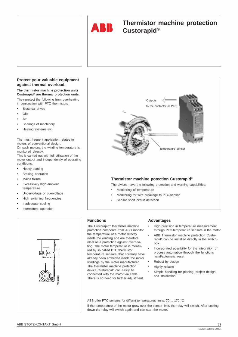
Thermistor machine protectionCustorapid ®
Thermistor machine potection Custorapid ®
The divices have the following protection and warning capabilities:
• Monitoring of temperature
• Monitoring for wire breakage to PTC-sensor
• Sensor short circuit detection
FunctionsThe Custorapid® thermistor machineprotection compents from ABB monitorthe temperature of a motor directlyinside the winding and are thereforeideal as a protection against overhea-ting. The motor temperature is measu-red by so called PTC thermistortemperature sensors, that normally havealready been embeded inside the motorwindings by the motor manufacturer.The thermistor machine protectiondevice Custorapid® can easily beconnected with the motor via cable.There is no need for further adjustment.
Advantages• High precision in temperature measurement
through PTC temperature sensors in the motor
• ABB Thermistor machine protection Custo-rapid® can be installed directly in the switch-box
• Incorporated possibility for the integration ofprocess automation through the functionshand/automatic reset
• Robust by design
• Highly reliable
• Simple handling for planing, project-designand installation
ABB offer PTC sensors for differnt temperatures limits: 70 ... 170 °C
If the temperature of the motor grow over the sensor limit, the relay will switch. After coolingdown the relay will switch again and can start the motor.
Outputs
to the contactor or PLC
temperature sensor
Protect your valuable equipmentagainst thermal overload.The thermistor machine protection unitsCustorapid ® are thermal protection units.
They protect the following from overheatingin conjunction with PTC thermistors
• Electrical drives
• Oils
• Air
• Bearings of machinery
• Heating systems etc.
The most frequent application relates tomotors of conventional design.On such motors, the winding temperature ismonitored directly.This is carried out with full utilisation of themotor output and independently of operatingconditions.
• Heavy starting
• Braking operation
• Mains failure
• Excessively high ambienttemperature
• Undervoltage or overvoltage
• High switching frequencies
• Inadequate cooling
• Intermittent operation

401SAC 1008 01 D0201
ABB STOTZ-KONTAKT GmbH
Thermistor machine protection Custorapid ® type C 105 / C 106of shockproof design for use in plant with high mechanical loadinge.g. traction, marine applications - overall width 36 mm
Ordering details
Control unitC 106-1
AB
B 8
4 16
22 R
Control unitC 105-1
AB
B 8
4 14
73 R
Thermistor machine protection Custorapid ®
for monitoring electrical drives, gas temperatures,
liquid temperatures and storage temperatures
Control unitC 505.01
SS
T 0
25 9
9
Control unitC 505.22
SS
T 0
22 9
9
Control unitC 506.03
SS
T 0
20 9
9
Type Connection voltage Order code Price Weight Pack.Uc per piece per piece unitV kg piece
C 106-1- 24 24V AC/DC GHC 106 0006 R 0005 0.200 1/5C 106-1- 127 110 ... 127V AC GHC 106 0006 R 0001 0.200 1/5C 106-1- 250 200 ... 250V AC GHC 106 0006 R 0002 0.200 1/5C 106-1- 440 380 ... 440V AC GHC 106 0006 R 0004 0.200 1/5
C 105-1- 24 24V AC/DC GHC 105 0105 R 0005 0.200 1/5C 105-1- 127 110 ... 127V AC GHC 105 0105 R 0001 0.200 1/5C 105-1- 250 200 ... 250V AC GHC 105 0105 R 0002 0.200 1/5C 105-1- 440 380 ... 440V AC GHC 105 0105 R 0004 0.200 1/5
Control unit type C 106, with 1 changeover contact, screw connection
Control unit type C 105, with 1 changeover contact, screw connection
Thermistor machine protection Custorapid ® type C505 / C506• All certifications for worldwide use (UL, CSA, GL, LRS, CE)• Can also be used with explosion-proof motors (PTB certification)• Ultra-modern production technology, latest design• Combined voltage: 110-120V AC and 220-240V AC in one unit (C506.03, C506.02)• Wide-span voltage power supply unit 24-240V AC/DC (C505.02, C506.12, C506.15, C506.22, C506.62)
Type Connection voltage Order code Price Weight Pack.Uc per piece per piece unitV kg piece
Compact control unit C 505.01
Auto-reset, 1 ch. contact (root bridged with A1) 1 fault LED (TRIPPED), overall width: 22.5 mm
C 505.01 –24 24V DC 1SAR 600 001 R 0005 0.120 1C 505.01 –110 110-120V AC 1SAR 600 001 R 0001 0.150 1C 505.01 –230 220-240V AC 1SAR 600 001 R 0002 0.150 1
Control unit C 505.02 (replaces C 105.02)
Auto-reset, 1 NO + 1 NC, 1 LED to indicate operating voltage (READY), 1 fault LED (TRIPPED),overall width: 22.5mm
C 505.02 –24 24V DC 1SAR 600 011 R 0005 0.120 1C 505.02 –110 110-120V AC 1SAR 600 011 R 0001 0.150 1C 505.02 –230 220-240V AC 1SAR 600 011 R 0002 0.150 1C 505.02 –W 24-240V AC/DC 1SAR 600 011 R 0010 0.150 1
Control unit C 506.03, (replaces C106.03)
Manual reset or reset by disconnecting power, 1 NO + 1 NC. Attention: Type K-2-S: 2 NO1 LED for indication of operating voltage (READY), 1 fault LED (TRIPPED), overall width: 22.5 mm.
C 505.03 –24 24V DC 1SAR 600 011 R 0005 0.120 1C 506.03 –K 110-120V/220-240V AC 1SAR 600 111 R 0006 0.150 1C 506.03 –K-2 S 110-120V/220-240V AC 1SAR 600 120 R 0006 0.150 1
Control unit C 506.02, (replaces C106.02)
Manual/auto/remote reset, non-volatile fault storage, 1 NO + 1 NC1 LED for indication of operating voltage (READY), 1 fault LED (TRIPPED), overall width: 22.5 mm.
C 506.02 –24 24V DC 1SAR 600 211 R 0005 0.120 1C 506.02 –K 110-120V / 220-240V AC 1SAR 600 211 R 0006 0.150 1
Control unit C 506.12, (replaces C106.12 and C106.13)
Manual/auto/remote reset, 2 changeover contacts, non-volatile fault storage, 1 LED for indication ofoperating voltage (READY), 1 fault LED (TRIPPED), sensor short-circuit detection, dynamic discontinuitydetection, overall width: 22.5 mm.

41ABB STOTZ-KONTAKT GmbH1SAC 1008 01 D0201
AB
B 8
21 2
09 R
Temperature sensorC 011
Thermistor machine protection Custorapid ®
for monitoring electrical drives, gas temperatures,
liquid temperatures and storage temperatures
Control unitC 506.12
Control unitC 506.22
Control unitC 506.62
SS
T 0
26 9
9S
ST
024
99
SS
T 0
21 9
9Ordering detailsDesignation Connection voltage Order code Price Weight Pack.
Uc per piece per piece unitType V kg piece
C506.12 –24 24V DC 1SAR 600 302 R 0005 0.120 1C506.12 –W 24-240V AC/DC 1SAR 600 302 R 0010 0.150 1
Control unit C 506.15
Manual/auto/remote reset, 2 changeover contacts, non-volatile fault storage, 1 LED for indication ofoperating voltage (READY), 1 fault LED (TRIPPED), sensor short-circuit detection, bistable output relay(retains its switching state even if the power supply is interrupted). For applications in chemistry andprocess technology, overall width: 22.5mm.
C506.15 –W 24-240V AC/DC 1SAR 600 402 R 0010 0.150 1
Control unit C 506.22, warning and shut-off
Manual/auto/remote reset, 1 NO + 1 changeover contact, two measuring circuits. If 1st switchingthreshold is exceeded, a warning signal (1 NO) is issued. If 2nd switching threshold is exceeded, motoris switched off (1 ch. contact). Non-volatile fault storage, 1 LED for warning indication (ALARM), 1 LED toindicate op. voltage (READY), 1 fault LED (TRIPPED), overall width: 22.5 mm.
C 506.22 –W 24-240V AC/DC 1SAR 600 511 R 0010 0.150 1
Control unit C 506.62 for multi-motor protection
Manual/auto/remote reset, 1 NO + 1 NC, monitoring of max. 6 motors, centralised fault indication,non-volatile fault storage, 1 LED for indication of operating voltage (READY), 1 fault LED (TRIPPED). OneLED for each measuring circuit (1-6) indicates in the event of a fault which motor caused the shut-off.Overall width: 45 mm
C506.62 –W 24-240V AC/DC 1SAR 600 612 R 0010 0.250 1
Accessories
Push-in link for screw fastening C 560.20
Mounting of control units C 505 / C 506 1SAR 390 000 R 2000 5 setswithout top-hat rail on mounting panelwith 1 set (2 pieces) of push-in linksÀ C = Combined voltage 110 / 230 V, AC Á W = Wide-span voltage 24 - 240 V, AC/DC
C 011- 70 70 white-brown GHC 011 0003 R 0001 0.002 3C 011- 80 80 white-white GHC 011 0003 R 0002 0.002 3C 011- 90 90 green-green GHC 011 0003 R 0003 0.002 3C 011-100 100 red-red GHC 011 0003 R 0004 0.002 3C 011-110 110 brown-brown GHC 011 0003 R 0005 0.002 3C 011-120 120 grey-grey GHC 011 0003 R 0006 0.002 3C 011-130 130 blue-blue GHC 011 0003 R 0007 0.002 3C 011-140 140 white-blue GHC 011 0003 R 0011 0.002 3C 011-150 150 black-black GHC 011 0003 R 0008 0.002 3C 011-160 160 blue-red GHC 011 0003 R 0009 0.002 3C 011-170 170 white-green GHC 011 0003 R 0010 0.002 3
Type Rated Colour coding Order code Price Weight Pack.temperature per pack. unit
° C unit kg piece
PTC thermistor temperature sensors, ordering details
Temperature sensor Type C 011, normal version to DIN 44081
C 0113-150 150 black-black GHC 011 0033 R 0008 0.006 1
Further reading
For application limits and test methods see "Instructions for Installation – Testing – Operation” of thethermistor machine protection Custorapid® with PTC thermistor temperature sensors.
Triple temperature sensor Type C 013
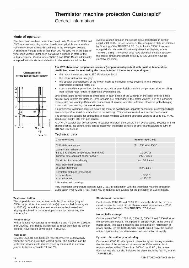
421SAC 1008 01 D0201
ABB STOTZ-KONTAKT GmbH
Technical data
Characteristics Sensor type C 011
Cold state resistance 50 ... 150 W at 25° C
Warm state resistance± 5 to 6 K of rated temperature, TNF (NAT) 10 000 ΩThermal time constant sensor open 1) 2.5 ... 3.5 s
Short circuit current density max. 50 A/mm2
Max. permitted voltageat sensor terminals max. 2.5 V
Permitted ambient temperature• short-term + 275° C• continuous + 175 ° C
1) Not embedded in windings.
PTC thermistor temperature sensors type C 011 in conjunction with the thermistor machine protectionCustorapid® Type C 105 (PTB Report No. on request) are suitable for the protection of EEx e motors.
AB
B 8
56 2
83
Characteristicof the temperature sensor
Thermistor machine protection Custorapid ®
General information
Mode of operationThe thermistor machine protection control units Custorapid® C505 andC506 operate according to the closed-circuit principle and thereforeself-monitor even against discontinuity in the connection voltage.A short-term voltage drop of less than 200 ms (100 ms in the case ofwide-span voltage units) does not cause a change in state of theoutput contacts. Control units C506.12 and C506.15 are additionallyequipped with short-circuit detection in the sensor circuit. In the
event of a short circuit in the sensor circuit (resistance in sensorcircuit < 20 Ω) the device is tripped. This equipment state is indicatedby flickering of the TRIPPED LED. Control units C506.12 are alsoequipped with dynamic discontinuity detection (flashing of theTRIPPED LED). The control units have electrical isolation betweenthe control circuit and sensor circuit (24V DC versions have noelectrical isolation).
The PTC thermistor temperature sensors (temperature-dependent with positive temperaturecoefficient) must be selected by the manufacturer of the motors depending on:
• the motor insulation class to IEC Publication 34-11• the motor utilisation category• the special characteristics of the motor, such as conductor cross-sections of the windings,
permissible overload factor etc.• special conditions prescribed by the user, such as permissible ambient temperature, risks resulting
from locked rotor, extent of permitted overloading etc.
One temperature sensor must be embedded in each phase of the winding. In the case of three-phasesquirrel cage motors for instance, three sensors are embedded in the stator winding. For pole-changingmotors with one winding (Dahlander connection), 3 sensors are also sufficient. However, pole-changingmotors with two windings require 6 sensors.If a preliminary winding is required before the motor is switched off, separate sensors for a correspondinglylower temperature must be embedded in the winding. They are connected to a second control unit.The sensors are suitable for embedding in motor windings with rated operating voltages of up to 660 V AC.Conductor length: 500 mm per sensor.A 14 V DV varistor can be connected in parallel to protect the sensors from overvoltages. Because of theircharacteristics, the control units can be used with thermistor sensors of other manufacturers to DIN 44081 and DIN 44 082.
Test/reset buttonThe tripped device can be reset with the blue button (only onC506.xx), provided the sensor circuit(s) have cooled down again(< 1500 Ω). In addition, the test function can be invoked andtripping simulated in the non-tripped state by depressing thebutton > 2 s.
Remote resetWith a floating NO contact at terminals Y1 and Y2 (not on C505.xxand C506.03) the tripped device can be reset provided the sensorcircuit(s) have cooled down again (< 1500 Ω).
Auto resetDevices C505.01 and C505.02 reset themselves automaticallywhen the sensor circuit has cooled down. This function can berealized in devices with remote reset by means of an externaljumper between terminals Y1 and Y2.
Short-circuit detection:
Control units C506.12 and C506.15 constantly check the sensor-circuit resistor for short circuit. Sensor circuit resistances < 20 Ωcause the device to trip. The TRIPPED LED flickers.
Non-volatile storage
Control units C506.02, C506.12, C506.15, C506.22 and C506.62 storethe device state (tripped / not tripped) in an EEPROM. In the event ofmains failure, this state is retained and is restored on resumption ofpower supply. On the C506.15 with bistable output relay, the positionof the output contacts is also retained on interruption of supply.
Dynamic discontinuity monitoring
Control unit C506.12 with dynamic discontinuity monitoring evaluatesthe rise time of the sensor circuit resistance. If the sensor circuitresistance rises within 200 ms from 3600 Ω to 12 kΩ , the devicedoes not just trip, but also indicates the discontinuity by flashing of theTRIPPED LED.

43ABB STOTZ-KONTAKT GmbH1SAC 1008 01 D0201
Indication of state by LEDs
READY LED (not on C505.01) Green Off Device not ready for operation, internal device faultOn Device ready for operation
TRIPPED LED Red Off Device in non-tripped state: normal operationOn Device in tripped state: excess temperatureFlashing Device in tripped state: sensor discontinuityFlickering Device in tripped state: sensor short circuit
ALARM-LED (only on C506.22) Yellow Off Alarm temperature not reached, alarm output not activeOn Alarm temperature reached, alarm output active
Thermistor machine protection Custorapid ®
Technical data
Control circuit
Connection voltage UC: Tolerance range:
24 V DC 0.85 x UC to 1.2 x UC (20.4 V to 28.8 V)110 - 120 V AC 0.85 x UC to 1.1 x UC (93.5 V to 132 V)220 - 240 V AC 0.85 x UC to 1.1 x UC (187 V to 264 V)
24 - 240 V AC/DC 0.85 x UC to 1.1 x UC (20.4 V to 264 V)
Rated frequency: 50 Hz / 60 Hz
Rated insulation voltage Ui: 300V
Rated impulse strength Uimp: 6 kV (C506.12 in wide-span voltage version) 4kV (other units)
Overvoltage category: III
Pollution degree: 3 (housing), 2 (PCB)
Sensor circuit
Max. number of sensors: 6
Cumulative cold resistance RF: - 1500 Ω
Switch-off resistance RFoff: 3.4 to 38 kΩ
Switch-on resistance RFon: 1.5 to 1.65 kΩ
Sensor circuit power consumption at RF - 1.5 kΩ < 5 mW
Current with short-circuited sensor circuit: - 1.2 mA
Sensor circuit voltage at RF= 4 kΩ - 4.3 V
Sensor circuit voltage on detection sensor rupture: - 30 V
Short-circuit detection RFKS (C506.12 and C506.15): < 20 Ω
Conductor lengths: Cross-section Control units Control unitswithout short- with short-circuit detection circuit detection
2.5 mm2 2 x 2800 m 2 x 250 m1.5 mm2 2 x 1500 m 2 x 150 m0.5 mm2 2 x 500 m 2 x 50 m
Auxiliary circuit output contacts
Continuous thermal current Ith: 5 A
Utilisation category:
AC-15 3 A / 240 VAC-14 3 A / 240 VDC-13 0.1 A / 240 V, 1 A / 24 V
Short-circuit protection: Diazed 6 A gL/gG
Rated insulation voltage Ui: 300 V
Rated impulse strength Uimp: 6 kV (C506.12 in wide-span voltage version)4 kV (other units)
Overvoltage category: III
Pollution degree: 3 (housing), 2 (PCB)

441SAC 1008 01 D0201
ABB STOTZ-KONTAKT GmbH
Control units type C 505 and C 506 are suitablefor direct temperature monitoring of EEx e motorsin accordance with VDE 0165/9.83 in conjunctionwith PTC thermistor temperature sensors to DIN44081 and DIN 44082.
The units bear the test mark of the "GermanNational Standards Laboratory" in Braunschweig– PTB Notification 91 (1981), page 122 –.
Control units with the adjacent testmark are interchangeable.
Thermistor machine protection Custorapid ®
PTB, Approvals
Explanation of symbols:
Normal version approved: rating plates bear the test mark if mandatory
Special design approved
No general mandatory test with the exception of special cases
(1) 300 V AC voltage max.(2) Special routine test
3.43 - PTC
Notes
In the case of tripping devices with DC operation, electrical isolation must be ensured by means ofa battery network or a safety isolating transformer according to DIN VDE 0551.
If tripping devices with AUTO RESET are used in EEx e applications, it must be ensured by thecontrol wiring that the machine being monitored does not restart independently.
In the case of tripping devices without short-circuit detection, the sensor circuit resistancemust be measured with a suitable measuring device on initial startup. In the case ofresistances < 50 Ω the sensor circuit must be checked for short circuit.
If using device C505.01 (no READY LED) or C506.15 (no change of switching state of output relayif control voltage fails) to protect EEx e motors, separate monitoring of the control voltage isrecommended.
If machines are equipped with PTC thermistortemperature sensors to DIN 44 081 or DIN 44082, the control units with test mark may also beused in place of control units stipulated in thePTB test certificates in each case. The PTB testcertificate for protective devices C 505.01, C505.02, C 506.02, C 506.03, C 506.12, C 506.15,C 506.22 and C 506.62 is available.
Thermistor machine protection Custorapid ® for EEx e motors
Approvals and certificatesDevice type Approvals Quality marks Ships’ classification societies
Test mark
Abbreviation SEV DEMKO NEMKO SEMKO Inspect CSA UL ÖVE PT B BV GL LRS DNV PRS RINa Reg.Validity Switzerl. Demnmark Norway Sweden Finland Canada USA Austria Germany France Germany Gr. Britain Norway Poland Italy Russia
Thermistor machine protection Custorapid ® and PTC thermistor temperature sensor
C 505.01
C 505.02
C 506.02
C 506.03
C 506.12
C 506.15
C 506.22
C 506.62
C 011 (2)(1)

45ABB STOTZ-KONTAKT GmbH1SAC 1008 01 D0201
Thermistor machine protection Custorapid ®
Type C 505 / C 506Connection examples, function diagrams
Connection examples Function diagrams
C 505.02
C 506.03
C 506.02
AUTO-RESET
MANUAL RESET
AUTO-RESET
AUTO / MANUAL /REMOTE RESET, Non-volatile
C 505.01

461SAC 1008 01 D0201
ABB STOTZ-KONTAKT GmbH
Thermistor machine protection Custorapid ®
Type C 505 / C 506Connection examples, function diagrams
Connection examples Function diagrams
C 506.12
C 506.15
C 506.22
C 506.62
AUTO / MANUAL / REMOTE RESET,Sensor short-circuit detection, non-volatile
AUTO / MANUAL / REMOTE RESET,bistable, sensor short-circuit detection, non-volatile
AUTO / MANUAL / REMOTE RESET,Alarm and shut-off (2 measuring circuits)
AUTO / MANUAL / REMOTE RESET,Multi-motor protection
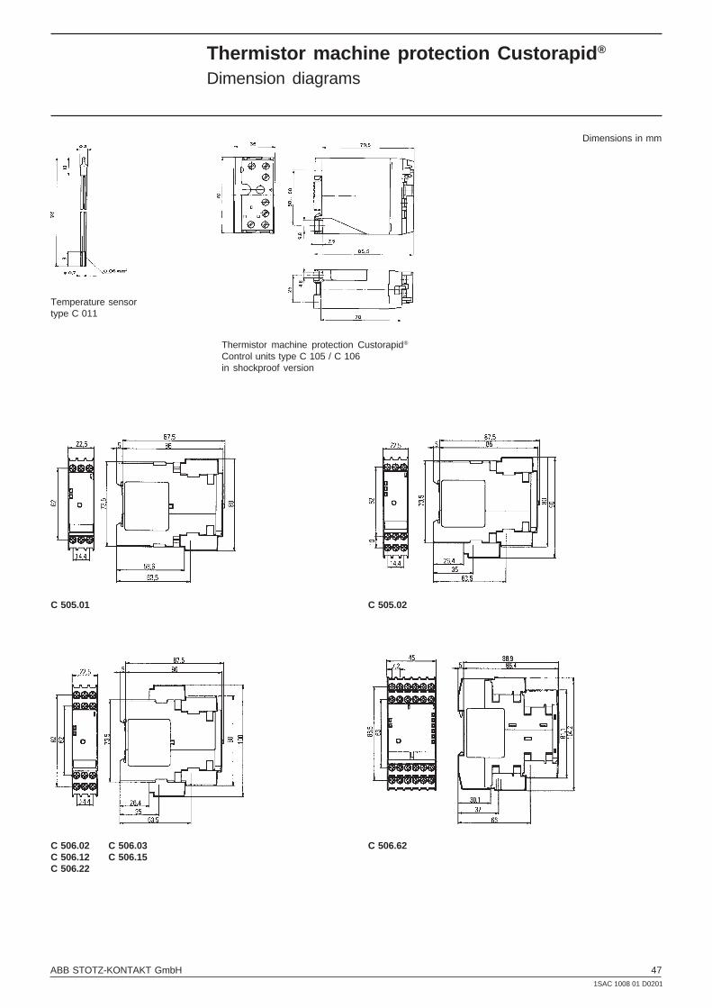
47ABB STOTZ-KONTAKT GmbH1SAC 1008 01 D0201
Thermistor machine protection Custorapid ®
Dimension diagrams
C 506.02 C 506.03C 506.12 C 506.15C 506.22
C 506.62
C 505.02C 505.01
Temperature sensortype C 011
Thermistor machine protection Custorapid®
Control units type C 105 / C 106in shockproof version
Dimensions in mm

ABB STOTZ-KONTAKT GmbHP.O.BOX 101680D-69006 HeidelbergTelephone ++49 62 21 / 701-00Telefax ++49 62 21 / 701-1115
Internet http://www.abb.de/sst
Pu
blic
atio
nno
: 1S
AC
100
8 01
D02
01P
rint
ed in
Ger
man
y (0
2/01
)


