12

1
Technical characteristics of a very broadband seismographic station atValguarnera (Sicily, Italy)
D. Reitano(1), A. Ursino(1), H. Langer(1)
(1)Istituto Nazionale di Geofisica e Vulcanologia – Sezione di Catania, Piazza Roma, 2- 95123 Catania (Italy).
Abstract
Goal of this report is to give some information about the data acquisition system and sensors of a verybroadband seismographic station at Valguarnera in Sicily. The actual configuration, and also a fewdetails about technical improvements, will be described.
Introduction
This paper describes the main features of the very broadband seismographic station in Valguarnera(VAE) located in central part of Sicily. This station was installed in 1994 and was set up originally in theframework of the POSEIDON project. It is now operated inside the seismic network of the IstitutoNazionale di Geofisica e Vulcanologia (INGV) - Sezione di Catania. The seismic station is a remotely-controlled unmanned acquisition system, which allows continuous and triggered recording of verybroadband and short-period data. The importance of VAE derives, above all, from the good siteconditions and its advanced instrumental characteristics. In fact the site has been selected by theCTBTO (C omprehensive Nuclear-Test-Ban T reaty O rganization) to be integrated to the IMS(International Monitoring System) which is dedicated to the surveillance and detection of nuclearexplosions. Actually the station VAE is integrated in the MEDNET very broadband seismic network,deployed in various countries around the Mediterranean Sea (Boschi et al., 1994; Mazza et al., 1998).On a local scale the data are used for microearthquake studies and the routine determination of the localmagnitudes.
1. Characteristics of the station
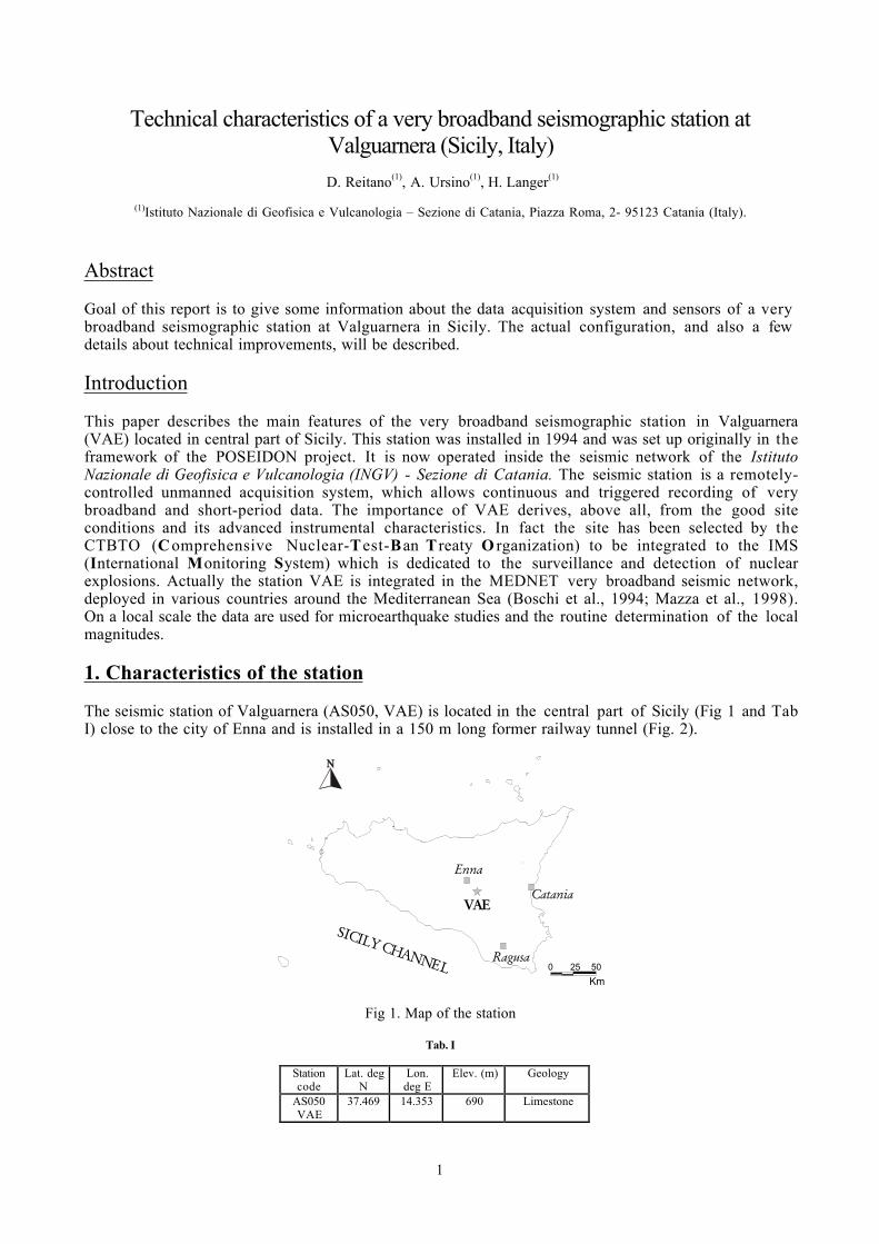
The seismic station of Valguarnera (AS050, VAE) is located in the central part of Sicily (Fig 1 and TabI) close to the city of Enna and is installed in a 150 m long former railway tunnel (Fig. 2).
VAECatania
Enna
SICILY CHANNELRagusa
0 25 50
Km
Fig 1. Map of the station
Tab. I
Stationcode
Lat. degN
Lon.deg E
Elev. (m) Geology
AS050VAE
37.469 14.353 690 Limestone
2
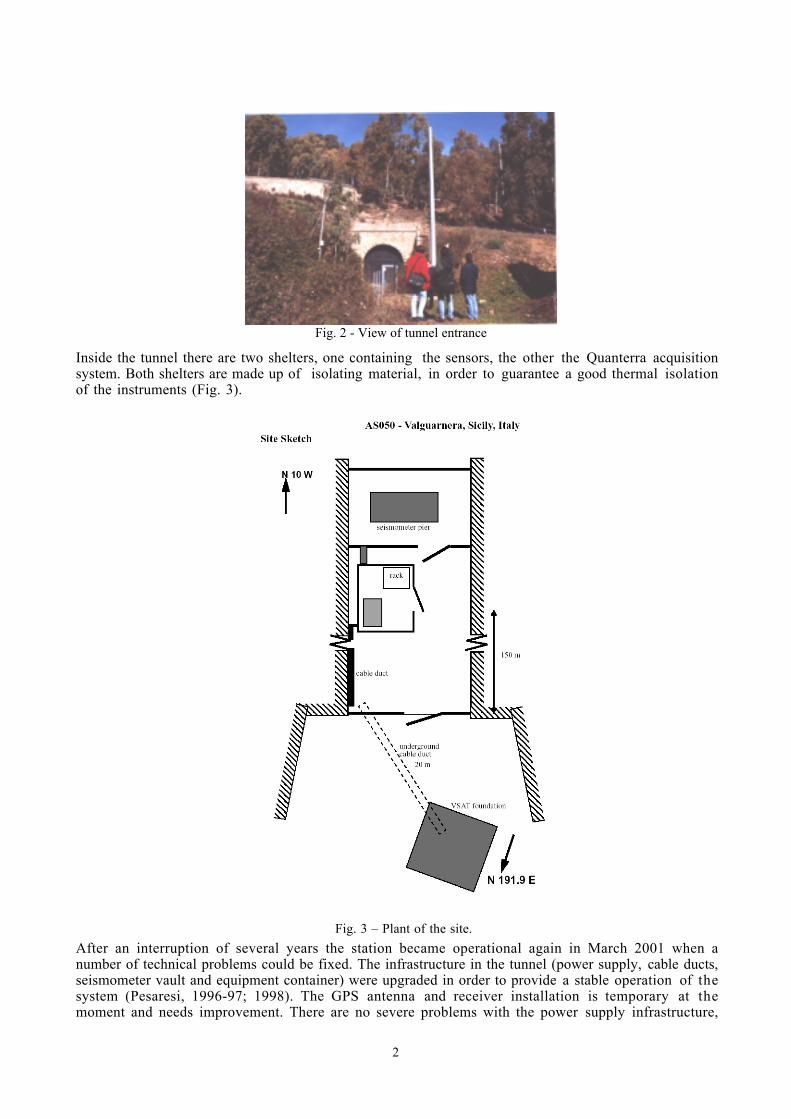
Inside the tunnel there are two shelters, one containing the sensors, the other the Quanterra acquisitionsystem. Both shelters are made up of isolating material, in order to guarantee a good thermal isolationof the instruments (Fig. 3).
After an interruption of several years the station became operational again in March 2001 when anumber of technical problems could be fixed. The infrastructure in the tunnel (power supply, cable ducts,seismometer vault and equipment container) were upgraded in order to provide a stable operation of thesystem (Pesaresi, 1996-97; 1998). The GPS antenna and receiver installation is temporary at themoment and needs improvement. There are no severe problems with the power supply infrastructure,
Fig. 2 - View of tunnel entrance
Fig. 3 – Plant of the site.

3
besides rare power outages of limited duration (no more than several hours). Actually the power supplysystem is buffered by a lead-acid battery, the installation of a UPS back up is foreseen.Previously a satellite link was installed in this site, but the antenna was removed about five years ago(Fig. 4). The concrete pad from this installation is still there and is used for the installation of a VSATantenna which will transfer the data to the data center of the CTBTO in Vienna.
Even though lightning is not felt to pose a great danger in this region, basic lightning protection for thepower supply and the VSAT should be included in the future upgrade.The Quanterra data acquisition system Q680 has a six-channel high resolution 24-bit digitizer with adynamic range as high as 140 dB and a wide frequency range. Actually various data streams are recordedwith sampling frequencies of 80, 20, 1, 0.1 and 0.01 Hz. This configuration provides a goodcompromise and an optimum acquisition system for a very broadband triaxial seismograph like the STS-1.The mass data storage consists of an internal 200 MByte SCSI disk drive with continuos and trigger dataand a 2 GByte streamer tape drive for continuos archiving of all data streams (Fig. 5). The data on thedisk-drive can be accessed to via a dial-up modem connection.
Fig. 4 - VSAT foundation seen from above.
Fig. 5 – Block diagram of acquiring data system.
4
1.1 Time accuracy
High-quality time information is critical to the operation of a seismic network. Although eachQuanterra datalogger contains an internal clock, the accuracy of the external clocks are much higher.The Quanterra uses the external clock as an absolute time base. If the external clock fails, the internalQuanterra clock is used until the external clock is replaced.In particular the time signal is compared against an external one, the 1 PPS signal derived from a GPSreceiver's output. From the difference in time, a control signal is derived and the internal clock isadjusted accordingly. Normally this is done by a phase locked loop in combination with a voltagecontrolled oscillator. If the difference is bigger than a selectable amount of time, the adjustment is doneinstantly.During normal operation the time base advance and retard control provides the capability to adjust theinternal oscillator without disturbing data acquisition. Adjustments in the order of µseconds permillisecond of the time base are allowed to smoothly synchronize the internal timing clocks with anexternal source or to simply adjust the internal clocks for known drift rates.Quanterra uses a GPS clock (Quanterra GPS1). This device, connected with the datalogger, transmits thePPM signal, while a RS232 output transmits the correct position and the complete time string. Becauseof the long distance (ca 150 m) it was recommendable to use two different RS232 – RS422 convertersand connect the devices with a RS485 line wire.
1.2 Communications
The ring buffer data (stored on the RAM and the hard-disk) are accessible by dial-up via public phoneline. Automated dial-up data retrieval is used at VAE for receiving selected event data in near-real-timefrom the Unified Acquiring Data Center (CUAD) of INGV, Sezione di Catania.
1.3 Sensors
The station is equipped with three Streckeisen STS-1 and with a Kinemetrics FBA-23.
Streckeisen STS-1
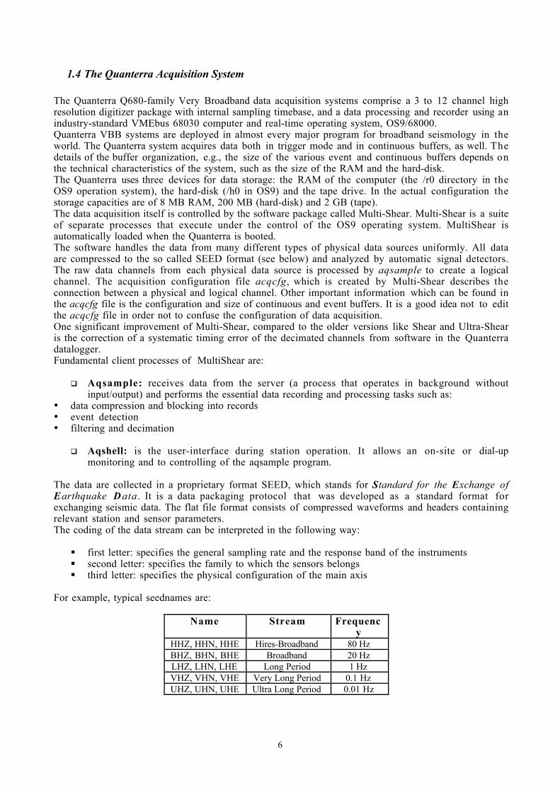
The STS-1 was designed in 1976 and is a Very Broadband (VBB) seismometer mainly dedicated to theregistration teleseismic earthquakes in the framework of global seismological studies.Its sensitivity is 2400 Vs/m with a dynamic range better than 140 dB in the frequency range of 0.0001Hz to 10 relative to 1 [m2/s3]. Special thermal enclosures (styrofoam), pressure (glass bell, vacuum-packed) and EMI shielding; glass plate installation must be used to take full advantage of the lowfrequency characteristics of the STS-1. Maximum 5 °C operational temperature changes are allowed,requiring very stable temperature control in seismic vaults (Trnkoczy, 1997)The Streckeisen STS-1 is a leaf-spring seismometer which employs a force-feedback system to extendthe bandwidth and linearity of the seismometer (Fig. 7).The bell jars provide thermal stability and protect the seismometer from hostile environmentalconditions. In fact, the three sensors are put in an evacuated glass bell, to reduce the noise introduced bydifferent variations (atmospheric, tilt and thermal) which change the buoyancy of the seismometer'smass.The bell is closed hermetically at its base by a glass plate, which itself is fixed on marble surface coveringa concrete cement block (Fig. 6).Furthermore the seismometers are located inside a protected room with robust walls that repair sensorsfrom environmental conditions (Wielandt and Streckeisen., 1982; Wielandt and Steim., 1986).
5
Kinemetrics FBA-23
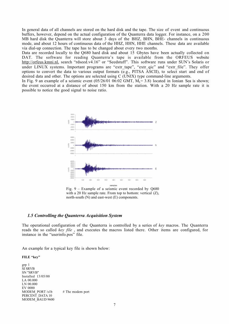
The FBA-23 is a spring-mass device using variable capacitance transduction and electromagneticfeedback. The output is fed back to the torquer coil, which is an integral part of the mass. From the coil,the feedback loop is completed through resistors Rh and Rs. This stiffens the system, thereby increasingthe natural frequency to 50 Hz. Resistor Ro and capacitor Co control the damping, normally adjusted t o70% critical. The acceleration sensitivity is controlled by the gain Kp of the post-amplifier. Aluminumpivot support blocks are used to maintain long-term drift-free stability of the accelerometer mass. TheFBA-23 has three accelerometers orthogonally mounted on an internal deck plate. Each of these units,housed in cast aluminum base and cover, is sealed to prevent the entrance of moisture and dirt. Theinstruments have full scale of ± 3.2 V and a noise level of ca 0.001 V peak to peak. In Fig. 8 theresponse curve of the sensor is shown.
0,0E+00
2,0E-01
4,0E-01
6,0E-01
8,0E-01
1,0E+00
-0,5 0,5 1,5 2,5
log Frequency [Hz]
Gai
n [1
.25
V /
g]
Fig. 8 – FBA-23: curve response
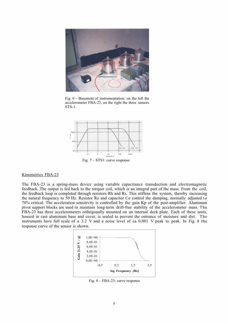
Fig. 6 – Basement of instrumentation: on the left theaccelerometer FBA-23, on the right the three sensorsSTS-1.
Fig. 7 – STS1: curve response
6
1.4 The Quanterra Acquisition System
The Quanterra Q680-family Very Broadband data acquisition systems comprise a 3 to 12 channel highresolution digitizer package with internal sampling timebase, and a data processing and recorder using anindustry-standard VMEbus 68030 computer and real-time operating system, OS9/68000.Quanterra VBB systems are deployed in almost every major program for broadband seismology in theworld. The Quanterra system acquires data both in trigger mode and in continuous buffers, as well. Thedetails of the buffer organization, e.g., the size of the various event and continuous buffers depends onthe technical characteristics of the system, such as the size of the RAM and the hard-disk.The Quanterra uses three devices for data storage: the RAM of the computer (the /r0 directory in theOS9 operation system), the hard-disk (/h0 in OS9) and the tape drive. In the actual configuration thestorage capacities are of 8 MB RAM, 200 MB (hard-disk) and 2 GB (tape).The data acquisition itself is controlled by the software package called Multi-Shear. Multi-Shear is a suiteof separate processes that execute under the control of the OS9 operating system. MultiShear isautomatically loaded when the Quanterra is booted.The software handles the data from many different types of physical data sources uniformly. All dataare compressed to the so called SEED format (see below) and analyzed by automatic signal detectors.The raw data channels from each physical data source is processed by aqsample to create a logicalchannel. The acquisition configuration file acqcfg, which is created by Multi-Shear describes theconnection between a physical and logical channel. Other important information which can be found inthe acqcfg file is the configuration and size of continuous and event buffers. It is a good idea not to editthe acqcfg file in order not to confuse the configuration of data acquisition.One significant improvement of Multi-Shear, compared to the older versions like Shear and Ultra-Shearis the correction of a systematic timing error of the decimated channels from software in the Quanterradatalogger.Fundamental client processes of MultiShear are:
Aqsample: receives data from the server (a process that operates in background withoutinput/output) and performs the essential data recording and processing tasks such as:
• data compression and blocking into records• event detection• filtering and decimation
Aqshell: is the user-interface during station operation. It allows an on-site or dial-upmonitoring and to controlling of the aqsample program.
The data are collected in a proprietary format SEED, which stands for Standard for the Exchange ofEarthquake Data. It is a data packaging protocol that was developed as a standard format forexchanging seismic data. The flat file format consists of compressed waveforms and headers containingrelevant station and sensor parameters.The coding of the data stream can be interpreted in the following way:
first letter: specifies the general sampling rate and the response band of the instruments second letter: specifies the family to which the sensors belongs third letter: specifies the physical configuration of the main axis
For example, typical seednames are:
Name Stream Frequency
HHZ, HHN, HHE Hires-Broadband 80 HzBHZ, BHN, BHE Broadband 20 HzLHZ, LHN, LHE Long Period 1 HzVHZ, VHN, VHE Very Long Period 0.1 HzUHZ, UHN, UHE Ultra Long Period 0.01 Hz
7
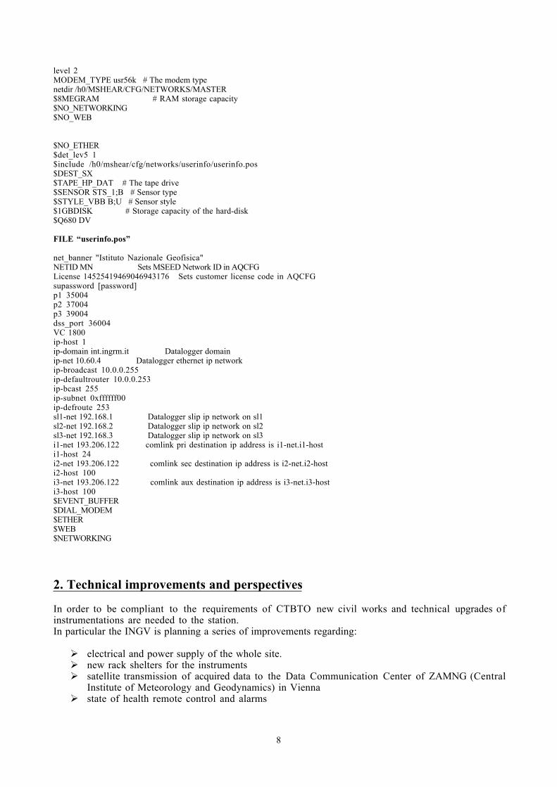
In general data of all channels are stored on the hard disk and the tape. The size of event and continuousbuffers, however, depend on the actual configuration of the Quanterra data logger. For instance, on a 200MB hard disk the Quanterra will store about 3 days of the BHZ, BHN, BHE- channels in continuousmode, and about 12 hours of continuous data of the HHZ, HHN, HHE channels. These data are availablevia dial-up connection. The tape has to be changed about every two months.Data are recorded locally to the Q680 hard disk and about 15 Gbytes have been actually collected onDAT. The software for reading Quanterra’s tape is available from the ORFEUS websitehttp://orfeus.kmni.nl, search “rdseed.v4.16” or “Seedstuff”. This software runs under SUN’s Solaris orunder LINUX systems. Important programs are “extr_tape”, “extr_qic” and “extr_file”. They offeroptions to convert the data to various output formats (e.g., PITSA ASCII), to select start and end ofdesired data and other. The options are selected using C (UNIX) type command-line arguments.In Fig. 9 an example of a seismic event (05/26/01 06:02 GMT, ML= 3.8) located in Ionian Sea is shown;the event occurred at a distance of about 150 km from the station. With a 20 Hz sample rate it ispossible to notice the good signal to noise ratio.
1.5 Controlling the Quanterra Acquisition System
The operational configuration of the Quanterra is controlled by a series of key macros. The Quanterrareads the so called key file , and executes the macros listed there. Other items are configured, forinstance in the “userinfo.pos” file.
An example for a typical key file is shown below:
FILE “key”
grp 1SI SRVBSN "SRVB"Installed 13/05/00LA 00.000LN 00.000EV 0000MODEM_PORT /s1b # The modem portPERCENT_DATA 10MODEM_BAUD 9600
Fig. 9 – Example of a seismic event recorded by Q680with a 20 Hz sample rate. From top to bottom: vertical (Z),north-south (N) and east-west (E) components.
8
level 2MODEM_TYPE usr56k # The modem typenetdir /h0/MSHEAR/CFG/NETWORKS/MASTER$8MEGRAM # RAM storage capacity$NO_NETWORKING$NO_WEB
$NO_ETHER$det_lev5 1$include /h0/mshear/cfg/networks/userinfo/userinfo.pos$DEST_SX$TAPE_HP_DAT # The tape drive$SENSOR STS_1;B # Sensor type$STYLE_VBB B;U # Sensor style$1GBDISK # Storage capacity of the hard-disk$Q680 DV
FILE “userinfo.pos”
net_banner "Istituto Nazionale Geofisica"NETID MN Sets MSEED Network ID in AQCFGLicense 14525419469046943176 Sets customer license code in AQCFGsupassword [password]p1 35004p2 37004p3 39004dss_port 36004VC 1800ip-host 1ip-domain int.ingrm.it Datalogger domainip-net 10.60.4 Datalogger ethernet ip networkip-broadcast 10.0.0.255ip-defaultrouter 10.0.0.253ip-bcast 255ip-subnet 0xffffff00ip-defroute 253sl1-net 192.168.1 Datalogger slip ip network on sl1sl2-net 192.168.2 Datalogger slip ip network on sl2sl3-net 192.168.3 Datalogger slip ip network on sl3i1-net 193.206.122 comlink pri destination ip address is i1-net.i1-hosti1-host 24i2-net 193.206.122 comlink sec destination ip address is i2-net.i2-hosti2-host 100i3-net 193.206.122 comlink aux destination ip address is i3-net.i3-hosti3-host 100 $EVENT_BUFFER$DIAL_MODEM$ETHER$WEB$NETWORKING
2. Technical improvements and perspectives
In order to be compliant to the requirements of CTBTO new civil works and technical upgrades ofinstrumentations are needed to the station.In particular the INGV is planning a series of improvements regarding:
electrical and power supply of the whole site. new rack shelters for the instruments satellite transmission of acquired data to the Data Communication Center of ZAMNG (Central
Institute of Meteorology and Geodynamics) in Vienna state of health remote control and alarms
9
3. Conclusions
This work illustrates the main characteristics of the AS050 VAE seismic station, and also gives the firstgrade of information regarding this acquiring system.This site has been selected by the CTBTO to be a part of the IMS which is dedicated to the surveillanceand detection of nuclear explosions for good site conditions and its high quality instrumentalcharacteristics.Data recorded (very broadband and short period data) by this station are embedded in research projectsdevoted to global and regional seismology (see e.g., MEDNET). The data are going to be exploited alsoon a local scale for microearthquake studies, such as the estimation of true WOOD-ANDERSONmagnitudes and seismic moments, as well as long period signals radiated from Mt. Etna volcano.
4. Acknowledgements
We are grateful to Prof. Stefano Gresta (University of Catania) for his useful suggestions to the paper.We also thank an anonymous reviewer for his comments which helped to improve the quality of theoriginal manuscript.
10
Bibliography
Berkeley Seismological Laboratory (1999-2000): Annual Report – Data Acquisition and NetworkEnhancements
Boschi E. and Morelli A. (1994). The MEDNET Program, Annali di Geofisica, XXXVII, 5, 1066-1070
Kinemetrics Inc. Web Site, URL http://www.kinemetrics.com/
Mazza S.,. Morelli A. and. Boschi E. (1998). Near real-time data collection and processing at MEDNET,EOS Trans., Am. Geophys. Union, 79, 569.
Mednet (Mediterranean Very Broadband Seismographic Network) Web Site, http://www.ingv.it/~roma/
Orfeus (Observatories and R esearch F acilities for E U ropean Seismology ) Web Site,http://orfeus.knmi.nl
Pesaresi D. (1996-97): Seismic Observatory in Terra Nova: the 1996-97 Field Report.
Pesaresi D. (1998). Installation and Maintenance of Very-Broad-Band Stations, ORFEUS workshop on"Installation and operation of broad-band seismograph stations", Praga, 1998.
Quanterra Inc. (1999) : Quanterra Multi-Shear, Software Configuration Guide
Quanterra Inc. (1993) : Q680/SXS-G Operation
Trnkoczy A. (1997): STS-1 and STS-2 Sensors in National Seismic Networks – Application Note #40,Kinemetrics S.A.
Wielandt E. and Streckeisen G. (1982): The leaf spring seismometer: design and performance, Bull.Seis. Soc. Am., 72, Part A, 2349-2367.
Wielandt E. and Steim J. (1986): A digital very broadband seismograph, Ann. Geophys., 4b, 227.


