Page 1 of 5 Technical Committee on Water Tanks (WAT-AAA) M E M O R A N D U M DATE: March 1, 2017 TO: Principal and Alternate Members of the Technical Committee on Water Tanks (WAT-AAA) FROM: Chad Duffy, NFPA Staff Liaison Office: (617) 984-7562 Email: [email protected]SUBJECT: AGENDA – NFPA 22 Second Draft Meeting (Fall 2017) Enclosed is the agenda for the Second Draft meeting for NFPA 22, Standard for Water Tanks for Private Fire Protection, which will be held at the Sheraton Baltimore Washington Airport Hotel, Linthicum, MD 1:00pm to 5:00pm ET on Tuesday March 21, 2017, and Wednesday, March 22, 2017 from 8:00am to 5:00pm ET. Please submit requests for additional agenda items to the chair at least seven days prior to the meeting, and notify the chair and staff liaison as soon as possible if you plan to introduce any first revisions at the meeting. All NFPA Technical Committee meetings are open to the public. Please contact me for information on attending a meeting as a guest. Read NFPA's Regulations Governing the Development of NFPA Standards (Section 3.3.3.2) for further information. Additional Meeting Information: See the Meeting Notice on the Document Information Page (www.nfpa.org/22next) for meeting location details. If you have any questions, please feel free to contact Elena Carroll, Project Administrator at 617-984-7952 or by email [email protected]. C. Standards Administration
Transcript
Page 1 of 5
Technical Committee on Water Tanks (WAT-AAA)
M E M O R A N D U M
DATE: March 1, 2017
TO: Principal and Alternate Members of the Technical Committee on Water Tanks (WAT-AAA)
SUBJECT: AGENDA – NFPA 22 Second Draft Meeting (Fall 2017)
Enclosed is the agenda for the Second Draft meeting for NFPA 22, Standard for Water Tanks for
Private Fire Protection, which will be held at the Sheraton Baltimore Washington Airport Hotel, Linthicum, MD 1:00pm to 5:00pm ET on Tuesday March 21, 2017, and Wednesday, March
22, 2017 from 8:00am to 5:00pm ET. Please submit requests for additional agenda items to the chair at least seven days prior to the meeting, and notify the chair and staff liaison as soon as possible if you plan to introduce any first revisions at the meeting. All NFPA Technical Committee meetings are open to the public. Please contact me for information on attending a meeting as a guest. Read NFPA's Regulations Governing the Development of NFPA Standards (Section 3.3.3.2) for further information. Additional Meeting Information:
See the Meeting Notice on the Document Information Page (www.nfpa.org/22next) for meeting location details. If you have any questions, please feel free to contact Elena Carroll, Project
Technical Committee on Water Tanks (WAT-AAA) NFPA 22 Second Draft Meeting (Fall 2017)
Tuesday, March 21, 2017, 1:00pm – 5:00pm ET and Wednesday March 22, 2017, 8:00am – 5:00pm ET
Sheraton Baltimore Washington Airport Hotel, Linthicum, MD
Page 2 of 5
AGENDA
Tuesday, March 21, 2017
1. Call to Order – 1:00 PM
2. Introductions and Attendance
3. Review Agenda
4. NFPA Staff Liaison Presentation and Review of Key Dates in Current Cycle
5. Chairman Comments
6. Approval of Previous Meeting Minutes
7. Act on Public Comments for NFPA 22
8. Adjourn – 5:00 PM
Wednesday, March 22, 2017
1. Call to Order – 8:00 AM
2. Act on Public Comments for NFPA 22
3. Review Task Group Reports
4. New business
5. Adjourn – 5:00 PM
Please submit requests for additional agenda items to the chair at least seven days prior to
the meeting.
Please notify the chair and staff liaison as soon as possible if you plan to introduce any
second revisions or committee comments at the meeting.
Technical Committee on Water Tanks (WAT-AAA) NFPA 22 Second Draft Meeting (Fall 2017)
Tuesday, March 21, 2017, 1:00pm – 5:00pm ET and Wednesday March 22, 2017, 8:00am – 5:00pm ET
Sheraton Baltimore Washington Airport Hotel, Linthicum, MD
Page 3 of 5
Key Dates for the Fall 2017 Revision Cycle
Public Input Closing Date January 7, 2016 Final Date for First Draft Meeting June 16, 2016 Posting of First Draft and TC Ballot August 4, 2016 Ballots Returned By August 25, 2016 Post Final First Draft September 8, 2016
Comment Closing Date November 17, 2016
Final Date for Second Draft Meeting May 18, 2017
Posting of Second Draft and TC Ballot June 29, 2017
Ballots Returned By July 20, 2017
Posting Final Second Draft August 3, 2017 Closing Date for Notice of Intent to Make a Motion
(NITMAM) August 31, 2017
Issuance of Consent Document (No NITMAMs) October 12, 2017
NFPA Annual Meeting June 4-7, 2018 Issuance of Document with NITMAM August 14, 2018
Technical Committee deadlines are in bold.
Technical Committee on Water Tanks (WAT-AAA) NFPA 22 Second Draft Meeting (Fall 2017)
Tuesday, March 21, 2017, 1:00pm – 5:00pm ET and Wednesday March 22, 2017, 8:00am – 5:00pm ET
Sheraton Baltimore Washington Airport Hotel, Linthicum, MD
Page 4 of 5
Meeting Preparation Committee members are strongly encouraged to review the published comments prior to the meeting and to be prepared to act on each item. Handout materials should be submitted to the chair at least seven days prior to the meeting. Only one posting of the comments will be made; it will be arranged in section/order and will be pre-numbered. This will be posted to the NFPA Document information pages located at www.nfpa.org/22. If you have trouble accessing the website please contact Elena Carroll at [email protected].
Mandatory Materials:
Last edition of the standard Meeting agenda Public input/comments Committee Officers' Guide (Chairs) Roberts’ Rules of Order (Chairs; An abbreviated version may be found in the
Regulations and Guiding Documents All committee members are expected to behave in accordance with the Guide for the Conduct of Participants in the NFPA Codes and Standards Development Process. All actions during and following the committee meetings will be governed in accordance with the Regulations Governing the Development of NFPA Standards. Failure to comply with these regulations could result in challenges to the standards-making process. A successful challenge on procedural grounds could prevent or delay publication of the document. The style of the document must comply with the Manual of Style for NFPA Technical Committee Documents.
Technical Committee on Water Tanks (WAT-AAA) NFPA 22 Second Draft Meeting (Fall 2017)
Tuesday, March 21, 2017, 1:00pm – 5:00pm ET and Wednesday March 22, 2017, 8:00am – 5:00pm ET
Sheraton Baltimore Washington Airport Hotel, Linthicum, MD
Page 5 of 5
General Procedures for Meetings
Use of tape recorders or other means capable of producing verbatim transcriptions of any NFPA Committee Meeting is not permitted.
Attendance at all NFPA Committee Meetings is open. All guests must sign in and identify their affiliation.
Participation in NFPA Committee Meetings is generally limited to committee members and NFPA staff. Participation by guests is limited to individuals, who have received prior approval from the chair to address the committee on a particular item, or who wish to speak regarding public input or comments that they submitted.
The chairman reserves the right to limit the amount of time available for any presentation.
No interviews will be allowed in the meeting room at any time, including breaks.
All attendees are reminded that formal votes of committee members will be secured by letter ballot. Voting at this meeting is used to establish a sense of agreement, but only the results of the formal letter ballot will determine the official action of the committee.
Note to Special Experts: Particular attention is called to Section 3.3(e) of the NFPA Guide for the Conduct of Participants in the NFPA Codes and Standards Development Process in the NFPA Directory. This section requires committee members to declare any interest they may represent, other than their official designation as shown on the committee roster. This typically occurs when a special expert is retained by and represents another interest category on a particular subject. If such a situation exists on a specific issue or issues, the committee member shall declare those interests to the committee and refrain from voting on any action relating to those issues.
Smoking is not permitted at NFPA Committee Meetings.
PrincipalSprinkler Fitters & Apprentices Local 69641-43 East Willow StreetMillburn, NJ 07041United Assn. of Journeymen & Apprentices of thePlumbing & Pipe Fitting IndustryAlternate: Gary Koenig
L 10/18/2011
WAT-AAA
Babanna Biradar
PrincipalBechtel India Pvt LtdKnowledge Park244 245, Udyog Vihar Phase IVGurgaon, Haryana, 122015 India
SE 3/2/2010WAT-AAA
John D. Campbell
PrincipalGlobal Fire Protection Group, LLC732 Spring Crest CourtFenton, MO 63026-3920
PrincipalPreload Incorporated60 Commerce DriveHauppauge, NY 11788-3929American Concrete Institute
M 1/1/1992WAT-AAA
Keith McGuire
PrincipalCST StoragePO Box 996Parsons, KS 67357Alternate: John J. Sweeney
M 1/1/1996
WAT-AAA
John M. Mitchard
PrincipalNuclear Service Organization1201 North Market Street, Suite 1100Wilmington, DE 19801Alternate: Andrew J. Brady
I 7/22/1999WAT-AAA
Bob D. Morgan
PrincipalFort Worth Fire Department1000 Throckmorton StreetFort Worth, TX 76102
E 10/27/2009
WAT-AAA
Leonard J. Ramo
PrincipalTelgian Corporation900 Circle 75 Parkway SESuite 680Atlanta, GA 30339-3084Alternate: Daniel S. Vandergriff
SE 08/17/2015WAT-AAA
Andrew Rosenwach
PrincipalRosenwach Tank Company, Inc.40-25 Crescent StreetLong Island City, NY 11101National Wood Tank Institute
M 4/1/1993
WAT-AAA
Daniel Sanchez
PrincipalCity of Los AngelesBuilding & Safety201 North Figueroa Street, Suite 400Los Angeles, CA 90012
E 10/29/2012WAT-AAA
Mark A. Sornsin
PrincipalSummit Companies11 15th Street SouthFargo, ND 58103
IM 3/2/2010
WAT-AAA
Gregory R. Stein
PrincipalTank Industry Consultants7740 West New York StreetIndianapolis, IN 46214Alternate: Patrick Jon Brown
SE 10/4/2001WAT-AAA
Owen Stevens
PrincipalFiber Tech Corporation7201 Lockport PlaceLorton, VA 22079-1524
M 08/11/2014
WAT-AAA
R. Greg Patrick
Voting AlternateTreasure Valley Fire Protection, Inc.2731 South Saturn WayBoise, ID 83709-2856American Fire Sprinkler Association
IM 8/5/2009WAT-AAA
Roland A. Asp
AlternateNational Fire Sprinkler Association, Inc.514 Progress Drive, Suite ALinthicum, MD 21090Principal: Kevin J. Kelly
IM 03/07/2013
WAT-AAA
Andrew J. Brady
AlternateNuclear Service Organization1201 North Market Street, Suite 1100Wilmington, DE 19801Principal: John M. Mitchard
I 8/9/2011WAT-AAA
Patrick Jon Brown
AlternateTank Industry Consultants7740 West New York StreetIndianapolis, IN 46214Principal: Gregory R. Stein
SE 10/29/2012
2
Address List No PhoneWater Tanks WAT-AAA
Combustible Dusts
Chad Duffy03/01/2017
WAT-AAA
Skip Donnell
AlternateLiberty Mutual Insurance CompanyEngineering Manager – Central3350 Carly LaneIndianapolis, IN 46235-9146Principal: Todd M. Kidd
I 03/03/2014WAT-AAA
Christine Fowler
AlternateCAL FIRE, Office of the State Fire Marshal1131 “S” StreetSacramento, CA 95811-6524Principal: Andrew M. Henning
E 08/17/2015
WAT-AAA
Jeremy W. John
AlternateFisher Engineering, Inc.10475 Medlock Bridge Road, Suite 520Johns Creek, GA 30097Principal: Douglas W. Fisher
SE 8/5/2009WAT-AAA
Gary Koenig
AlternateSprinkler Fitters Local Union 69641-43 East Willow StreetMillburn, NJ 07041United Assn. of Journeymen & Apprentices of thePlumbing & Pipe Fitting IndustryPrincipal: Kevin P. Bellew
L 10/29/2012
WAT-AAA
John J. Sweeney
AlternateSmith Engineered Storage Products Company345 Harvestore DriveDekalb, IL 60115Principal: Keith McGuire
M 1/15/1999WAT-AAA
Daniel S. Vandergriff
AlternateTelgian Corporation12250 Weber Hill Road, Suite 230St. Louis, MO 63127Principal: Leonard J. Ramo
SE 10/18/2011
WAT-AAA
Chad Duffy
Staff LiaisonNational Fire Protection Association1 Batterymarch ParkQuincy, MA 02169-7471
1. Chairman Robert M. Gagnon called the meeting to order at 12:00 pm ET on April 26th and welcomed the committee.
2. Introductions and Attendance was completed.
3. Chairman Robert M. Gagnon reviewed the agenda and provided introductory and procedural information.
4. Staff Liaison Chad Duffy provided a brief presentation covering committee member responsibilities, actions, revision cycle and the new process.
5. Chairman presented his comments. 6. The meeting minutes of April 9th and 20th, 2012 were reviewed and accepted.
7. The committee proceeded to review and act on the public input.
8. Meeting adjourned at 5:00 pm ET
Day 2
April 27, 2016 – 12 PM-5 PM ET 1. Chairman Robert M. Gagnon called the meeting to order at 8:00 am ET on April 27th.
2. Attendance was completed.
3. The committee proceeded to review and act on the public input.
4. The following task groups were structured.
TG on PI 6 & 7 TG on Tank Heating
TG on Table 9.1 TG on Conversions
Doug Wilson - Chair
Todd Kidd - Chair Chris Culp - Chair Chris Culp - Chair
Chris Culp Roland Asp Mark Sornsin Jeremy John Keith McGuire Andrew Rosenwach John Campbell Mark Sornsin Andrew Henning Owen Stevens John Mitchard
5. Next meeting to be announced.
6. Meeting adjourned at 10:30 am ET
Attendance: Principals Robert Gagnon Chris Butts John Campbell Christopher Culp Joseph Fowler Andrew Henning Jack Hillman Todd Kidd Keith McGuire John Mitchard Bob Morgan Leonard Ramo Andrew Rosenwach Mark Sornsin Owen Stevens Douglas Wilson Alternates Roland Asp Skip Donnell Jeremy John Gary Koenig Daniel Vandergriff Chad Duffy, NFPA Staff Liaison
Public Comment No. 13-NFPA 22-2016 [ Section No. 2.3.8 ]
2.3.8 AWWA Publications.
American Water Works Association, 6666 West Quincy Avenue, Denver, CO 80235.
AWWA C652, Disinfection of Water-Storage Facilities, 2011.
AWWA D100, Welded Steel Tanks for Water Storage, 2011.
Statement of Problem and Substantiation for Public Comment
AWWA D103 - AWWA issued an addendum to D103 incorporating important changes to the standard. The reference should incorporate the addendum.
AWWA D108. This reference is needed for a new reference proposed for Sec. 6.2.3.2.
Related Public Comments for This Document
Related Comment Relationship
Public Comment No. 14-NFPA 22-2016 [Section No. 6.2.3.2]
Related Item
Public Input No. 1-NFPA 22-2015 [Chapter 2]
Submitter Information Verification
Submitter Full Name: Leslie Scott
Organization: Paso Robles Tank – Brown-Minneapolis Tank, Inc.
Street Address:
City:
State:
Zip:
Submittal Date: Wed Nov 16 00:37:02 EST 2016
National Fire Protection Association Report http://submittals.nfpa.org/TerraViewWeb/ContentFetcher?commentPara...
1 of 99 11/28/2016 10:21 AM
Public Comment No. 3-NFPA 22-2016 [ Section No. 4.5.1 [Excluding any Sub-Sections] ]
In addition to complying with the requirements of this standard, it is expected that the manufacturers ofapproved structures will also follow the spirit of the standard by using their experience and ability to createstructures that shall prove reliable under all specified conditions The workmanship shall meet allrequirements of AWWA D100 .
Statement of Problem and Substantiation for Public Comment
This section deals with workmanship. It is unreasonable to expect a manufacturer to meet additional requirements that the technical committee responsible for this standard cannot identify and delineate.
As written, the language does not provide specific requirements which can lead to conflict between contractor, owner and AHJ.
If there are sections of NFPA 22 that do not include sufficient requirements such that the manufacturer would be expected to provide designs, details or methods to provide adequate equipment, then the technical committee should address these sections and correct the deficiencies.
This standard does not include provisions for all important aspects of welded steel tank construction and only references AWWA D100 for specific requirements. This proposed change will eliminate the unenforceable language of unspecified requirements and establish AWWA D100 for workmanship standards.
Related Item
Public Input No. 6-NFPA 22-2015 [Chapter 5]
Submitter Information Verification
Submitter Full Name: Leslie Scott
Organization: Paso Robles Tank - Brown-Minneapolis Tank, Inc.
Street Address:
City:
State:
Zip:
Submittal Date: Tue Nov 08 16:24:32 EST 2016
National Fire Protection Association Report http://submittals.nfpa.org/TerraViewWeb/ContentFetcher?commentPara...
2 of 99 11/28/2016 10:21 AM
Public Comment No. 5-NFPA 22-2016 [ Sections 4.10.2, 4.10.3 ]
Sections 4.10.2, 4.10.3
4.10.2
The workmanship shall be of such quality that defects or injuries are not produced during manufacture orerection that cause the specified unit stresses to be exceeded under any specified design loads .
4.10.3
Specified unit stresses shall not be exceeded.
<delete this section>
Statement of Problem and Substantiation for Public Comment
It is unreasonable to state that defects or injuries to material may not produced during erection without strict definition of 'defects or injuries'. Instead, any defects should be repaired or remediated to meet the requirements of the standard. AWWA D100, for instance, has allowable tolerances for shape and for specific loading conditions requires the manufacture to confirm that the as-built structure conforms to the shape tolerances in order to validate the basis of design. This change aligns the requirements to a reasonable requirement in line with the requirements of tank standards.
Related Item
Public Input No. 6-NFPA 22-2015 [Chapter 5]
Submitter Information Verification
Submitter Full Name: Leslie Scott
Organization: Paso Robles Tank - Brown-Minneapolis Tank, Inc.
Street Address:
City:
State:
Zip:
Submittal Date: Wed Nov 09 16:02:01 EST 2016
National Fire Protection Association Report http://submittals.nfpa.org/TerraViewWeb/ContentFetcher?commentPara...
3 of 99 11/28/2016 10:21 AM
Public Comment No. 24-NFPA 22-2016 [ Section No. 4.12.6.1 ]
4.12.6.1
All steel columns and struts shall be designed in accordance with AWWA D100. the applicable AWWA tankdesign standard for the type of tank being constructed. When no AWWA design standard exists for thetype of tank being constructed, then steel columns and struts shall be design in accordance with AISC 360.
Statement of Problem and Substantiation for Public Comment
As written, this sections requires steel columns and struts to be designed in accordance with AWWA D100 even if the tank design would generally follow AWWA D103, AWWA D110, AWWA D115, AWWA D120 or AWWA D121. This revision provides clarity to the supposed intent.
I agree with the Technical Committee's response on Public Input #6 to create a Task Group to review Chapter 5 in its entirety to compare and align with AWWA standards. The same effort should be extended to Chapter 4 in addition to other relevant Chapters and annexes.
Related Item
Public Input No. 6-NFPA 22-2015 [Chapter 5]
Submitter Information Verification
Submitter Full Name: Leslie Scott
Organization: Paso Robles Tank – Brown-Minneapolis Tank, Inc.
Street Address:
City:
State:
Zip:
Submittal Date: Fri Nov 18 00:50:32 EST 2016
National Fire Protection Association Report http://submittals.nfpa.org/TerraViewWeb/ContentFetcher?commentPara...
4 of 99 11/28/2016 10:21 AM
Public Comment No. 21-NFPA 22-2016 [ Section No. 4.14.1.1 ]
4.14.1.1
OSHA-compliant (29 CFR 1910) standard railing shall be placed around the roof manholes roof hatch(es)and other accessories that require access.
Statement of Problem and Substantiation for Public Comment
This standard does not use the terminology 'roof manhole', only 'roof hatch'. See Sec. 5.7.3, 5.7.4, 5.7.5, 5.7.6, 6.4.1.1.1, 8.7.5 and 8.7.6.
I agree with the Technical Committee's response on Public Input #6 to create a Task Group to review Chapter 5 in its entirety to compare and align with AWWA standards. This effort should also coordinate the requirements of Chapters 4, 5, 6, 12, 13, 14, 17, and 18 with all other requirements and reference standards.
Related Item
Public Input No. 6-NFPA 22-2015 [Chapter 5]
Submitter Information Verification
Submitter Full Name: Leslie Scott
Organization: Paso Robles Tank – Brown-Minneapolis Tank, Inc.
Street Address:
City:
State:
Zip:
Submittal Date: Thu Nov 17 23:16:15 EST 2016
National Fire Protection Association Report http://submittals.nfpa.org/TerraViewWeb/ContentFetcher?commentPara...
5 of 99 11/28/2016 10:21 AM
Public Comment No. 6-NFPA 22-2016 [ Sections 5.2.1.1, 5.2.1.2 ]
Sections 5.2.1.1, 5.2.1.2
5.2.1.1 Plates.
Plate materials shall be of open-hearth, electric furnace, or basic oxygen process steel that conforms toAWWA D100 and one of the following ASTM specifications:
(1) ASTM A36/A36M
(2) ASTM A283/A283M, Grades A, B, C, and D
5.2.1.2 1.1
Where plates of thicknesses greater than 3⁄4 in. (19.1 mm) are used, ASTM A283/A283M, Grade D, shallnot be used. ASTM A131/A131M, Grades A, B, and C; or ASTM A516/A516M, Grades 55 and 60, shall beused as alternatives.
5.2.1.1.2
ASTM A283, grade A steel is to be used only for nonstructural items such as clips, roof sheets, and otherlow-stressed components less than 1 in. (25 mm) thick.
<renumber remaining sections>
Statement of Problem and Substantiation for Public Comment
AWWA D100 does not allow ASTM Grade A to be used for shell plates because the specified minimum yield strength is considered too low. Since special restrictions are provided in 5.2.1.2 for ASTM A283 Grade D, this proposed restriction on Grade A should be added to this section.
If the desire is to merely make reference to AWWA D100, then delete Sec. 5.2.1.2 since D100 already has restrictions on use of ASTM A283 Grade D. NOTE: D100 only limits A283 Grade D to ¾ inch for use as shell plate but not for other applications. Also, D100 already includes provisions for alternate materials, so the list of alternate in this section would not be needed if these requirements were deferred to AWWA D100. Also, D100 contains other material restrictions not listed in NFPA 22.
ADDITIONAL COMMENTARYMany requirements in NFPA 22 are duplicative requirements to those contained in AWWA tank standards. If the intent of the Technical Committee is that the various tank types at least comply with the minimum requirements of the applicable AWWA standard, then it is recommended that the standard be revised by incorporating that statement and then incorporating any additional special provisions above the AWWA minimum requirements that are deemed necessary by the Technical Committee for tanks to adequately serve fire protection needs. By duplicating limited sections of AWWA tank standards into the NFPA standard, then it is incumbent on the Technical Committee to remain apprised in changes to the requirements in those AWWA standards and keep the NFPA document current. Based on the submitter's review of this NFPA standard, many requirements appear to have not be reviewed for an excessive number of years and editions of related standards.
It is unclear why the Technical Committee has chosen to not require compliance with all requirements of AWWA standards (D100 in this case) but instead only requires compliance of specific sections for specific considerations. It is the submitter's opinion that the requirements of this standard and the limited references to AWWA standards omit many important requirements in the design of a fire protection storage tank that are considered as minimum requirements for water storage tanks under the AWWA standards.
If the Technical Committee believes that the requirements of the relevant AWWA standards are insufficient such that some of the out of date requirements of this standard should stand as minimum requirements, then this submitter recommends that the Technical Committee submit proposed changes to AWWA for those requirements.
Related Item
National Fire Protection Association Report http://submittals.nfpa.org/TerraViewWeb/ContentFetcher?commentPara...
6 of 99 11/28/2016 10:21 AM
Public Input No. 6-NFPA 22-2015 [Chapter 5]
Submitter Information Verification
Submitter Full Name: Leslie Scott
Organization: Paso Robles Tank – Brown-Minneapolis Tank, Inc.
Street Address:
City:
State:
Zip:
Submittal Date: Thu Nov 10 15:59:16 EST 2016
National Fire Protection Association Report http://submittals.nfpa.org/TerraViewWeb/ContentFetcher?commentPara...
7 of 99 11/28/2016 10:21 AM
Public Comment No. 7-NFPA 22-2016 [ Section No. 5.2.1.3 ]
5.2.1.3 Basis of Furnishing Plates.
Plates shall be furnished, based on weight, with permissible underrun and overrun in accordance with thetolerance table for plates ordered to weight in ASTM A 6 or ASTM A20, as applicable to the particular steelspecification .
Statement of Problem and Substantiation for Public Comment
In a previous revision cycle it was noted that ASTM A6 did not apply to steel produced to ASTMA516 or ASTM A285 specifications. However, ASTM A6 does apply to ASTM A36, ASTM A283 and ASTM A131 specifications.
The text was incorrectly revised in previous revisions.
It is unclear why the Technical Committee has chosen to not require compliance with all requirements of AWWA standards (D100 in this case) but instead only requires compliance of specific sections for specific considerations. It is the submitter's opinion that the requirements of this standard and the limited references to AWWA standards omit many important requirements in the design of a fire protection storage tank that are considered as minimum requirements for water storage tanks under the AWWA standards.
If the Technical Committee believes that the requirements of the relevant AWWA standards are insufficient such that some of the out of date requirements of this standard should stand as minimum requirements, then this submitter recommends that the Technical Committee submit proposed changes to AWWA for those requirements.
Related Item
Public Input No. 6-NFPA 22-2015 [Chapter 5]
Submitter Information Verification
Submitter Full Name: Leslie Scott
Organization: Paso Robles Tank – Brown-Minneapolis Tank, Inc.
Street Address:
City:
State:
Zip:
Submittal Date: Thu Nov 10 16:25:23 EST 2016
National Fire Protection Association Report http://submittals.nfpa.org/TerraViewWeb/ContentFetcher?commentPara...
8 of 99 11/28/2016 10:21 AM
Public Comment No. 8-NFPA 22-2016 [ Section No. 5.4 ]
5.4 Unit Stresses.
The maximum stresses in pounds per square inch (megapascals) that are produced by the loads specifiedin Sections 4.12 and 5.3, or any combination of them, shall not exceed the values in Table 5.4 plus theallowable increased per Sec. 4. 12.7.1, if applicable .
Table 5.4 Maximum Stresses
psi MPa
Tension: On net section, rolled steel 15,000 103.43
Tension:
Anchor bolts†
Mild steel
ASTM A36/A36M or ASTM F1554–36 15,000 103.43
ASTM F1554–55 (weldable) 18,750 129.29
High-strength steel
ASTM A193–B7
1 1 ⁄ 4 in. ≤ diameter ≤ 2 1 ⁄ 2 in. 31,250 215.48
2 1 ⁄ 2 in. ≤ diameter ≤ 4 in. 28,750 198.24
ASTM F1554–105
1 1 ⁄ 4 in. ≤ diameter ≤ 3 in. 31,250 215.48
Tension: Cast steel
Bending:
Tension on extreme fibers, except column base plates 15,000* 103.43
Column base plates 20,000 137.90
Compression on extreme fibers of rolled sections, and plate girders andbuilt-up members for values as follows:
15,000 103.43
9,000,000 62,055
where l is the unsupported length; d is the depth of the member; b is the width; and t is the thicknessof its compression flange; all in in. (mm); except that l shall be assumed to be twice the length of thecompression flange of a cantilever beam not fully stayed at its outer end against translation or rotation.
Pins, extreme fiber 22,500 155.15
Cast steel 11,250 77.57
*For materials with Fy = 36,000 psi, the allowable stress may be taken as 18,000 psi.
†On area based on diameter at root of threads.
Statement of Problem and Substantiation for Public Comment
National Fire Protection Association Report http://submittals.nfpa.org/TerraViewWeb/ContentFetcher?commentPara...
9 of 99 11/28/2016 10:21 AM
Table 5.4 does not address the increase allowed by 4.12.7.1. As written, Sec. 5.4 overrides the increase allowed by Sec. 4.12.7.1 by specifically requiring that Table 5.4 stress levels not be exceeded for ALL load cases, including wind and seismic, so this change is needed to include the stress increase.
It is unclear why the Technical Committee has chosen to not require compliance with all requirements of AWWA standards (D100 in this case) but instead only requires compliance of specific sections for specific considerations. It is the submitter's opinion that the requirements of this standard and the limited references to AWWA standards omit many important requirements in the design of a fire protection storage tank that are considered as minimum requirements for water storage tanks under the AWWA standards. In the case of this comment, the erroneous language would make compliant structures more costly by exceeding relevant industry requirements, including NFPA 22 itself.
Related Item
Public Input No. 6-NFPA 22-2015 [Chapter 5]
Submitter Information Verification
Submitter Full Name: Leslie Scott
Organization: Paso Robles Tank – Brown-Minneapolis Tank, Inc.
Street Address:
City:
State:
Zip:
Submittal Date: Mon Nov 14 16:00:02 EST 2016
National Fire Protection Association Report http://submittals.nfpa.org/TerraViewWeb/ContentFetcher?commentPara...
10 of 99 11/28/2016 10:21 AM
Public Comment No. 9-NFPA 22-2016 [ Section No. 5.4 ]
National Fire Protection Association Report http://submittals.nfpa.org/TerraViewWeb/ContentFetcher?commentPara...
11 of 99 11/28/2016 10:21 AM
5.4 Unit Stresses.
National Fire Protection Association Report http://submittals.nfpa.org/TerraViewWeb/ContentFetcher?commentPara...
12 of 99 11/28/2016 10:21 AM
The maximum stresses in pounds per square inch (megapascals) that are produced by the loads specifiedin Sections 4.12 and 5.3, or any combination of them, shall not exceed the values in Table 5.4.
Table 5.4 Maximum Stresses
psi MPa
Tension: On net section, rolled steel 15,000 103.43
Tension:
Anchor bolts†
Mild steel
ASTM
ASTM A36/A36M or ASTM F1554–36 15,000 103.43
ASTM
ASTM F1554–55 (weldable) 18,750 129.29
High
High -strength steel
ASTM A193–B7
1 1 ⁄ 4 in. ≤ diameter ≤ 2 1 ⁄ 2 in. 31,250 215.48
2 1 ⁄ 2 in. ≤ diameter ≤ 4 in. 28,750 198.24
ASTM
ASTM F1554–105
1
1 1 ⁄ 4 in. ≤ diameter ≤ 3 in. 31,250 215.48
Tension: Cast steel 11,250 77.57
Bending:
Tension on extreme fibers, except column base plates 15,000* 103.43
Column base plates 20,000 137.90
Compression on extreme fibers of rolled sections, and plate girders and built-upmembers for values as follows:
15,000 103.43
9,000,000 62,055
(see attachment
for corrected value)
(see attachment
for corrected value)
where l is the unsupported length; d is the depth of the member; b is the width; and t is thethickness of its compression flange; all in in. (mm); except that l shall be assumed to be twice the lengthof the compression flange of a cantilever beam not fully stayed at its outer end against translation orrotation.
Pins, extreme fiber 22,500 155.15
Cast steel 11,250 77.57
*For materials with Fy = 36,000 psi, the allowable stress may be taken as 18,000 psi.
National Fire Protection Association Report http://submittals.nfpa.org/TerraViewWeb/ContentFetcher?commentPara...
13 of 99 11/28/2016 10:21 AM
†On area based on diameter at root of threads.
Additional Proposed Changes
File Name Description Approved
NFPA_22_-_Table_5.4_Corrections_LDS_2016_.pdf
Corrections to Table 5.4. Online editor does not allow proper formatting of table contents.
Statement of Problem and Substantiation for Public Comment
The table as printed is confusing and incomplete and inaccurate. Revise Table 5.4 to correct inaccuracies, provide missing information, and reformat for clarity.
1. For clarity of the groupings of members, add 'Anchor Bolts' for heading of second category rather than appearing to be a third category.
2. For clarity of the groupings of members, indent the two subcategories under anchors bolts (mild steel and high strength steel).
3. Add the values of allowable tension for cast steel where the values are missing.
4. For bending compression on rolled sections where ld/bt does not exceed 600, move the values down in the table to line up with the category.
5. For bending compression on rolled sections where ld/bt does exceeds 600, correct the allowable values to read properly as fractions as shown in the attachment.
ADDITIONAL COMMENTARYMany requirements in NFPA 22 are duplicative requirements to those contained in AWWA tank standards. If the intent of the Technical Committee is that the various tank types at least comply with the minimum requirements of the applicable AWWA standard, then it is recommended that the standard be revised by incorporating that statement and then incorporating any additional special provisions above the AWWA minimum requirements that are deemed necessary by the Technical Committee for tanks to adequately serve fire protection needs. By duplicating limited sections of AWWA tank standards into the NFPA standard, then it is incumbent on the Technical Committee to remain apprised in changes to the requirements in those AWWA standards and keep the NFPA document current. Based on the submitter's review of this NFPA standard, many requirements appear to have not be reviewed for an excessive number of years and editions of related standards.
It is unclear why the Technical Committee has chosen to not require compliance with all requirements of AWWA standards (D100 in this case) but instead only requires compliance of specific sections for specific considerations. It is the submitter's opinion that the requirements of this standard and the limited references to AWWA standards omit many important requirements in the design of a fire protection storage tank that are considered as minimum requirements for water storage tanks under the AWWA standards.
If the Technical Committee believes that the requirements of the relevant AWWA standards are insufficient such that some of the out of date requirements of this standard should stand as minimum requirements, then this submitter recommends that the Technical Committee submit proposed changes to AWWA for those requirements.
Related Item
Public Input No. 6-NFPA 22-2015 [Chapter 5]
Submitter Information Verification
Submitter Full Name: Leslie Scott
Organization: Paso Robles Tank – Brown-Minneapolis Tank, Inc.
Street Address:
National Fire Protection Association Report http://submittals.nfpa.org/TerraViewWeb/ContentFetcher?commentPara...
14 of 99 11/28/2016 10:21 AM
City:
State:
Zip:
Submittal Date: Mon Nov 14 16:07:35 EST 2016
National Fire Protection Association Report http://submittals.nfpa.org/TerraViewWeb/ContentFetcher?commentPara...
15 of 99 11/28/2016 10:21 AM
COMMENTED PREVIOUSLYWITH SPECIFIC CORRECTIONS.THESE ARE SUPPOSED TO BE FRACTIONS. SEE BELOW.
HEADING. ADD HERE AND
INDENT
in excess of 600bt
ld
bt
ld000,000,9
bt
ld055,62
MOVE DOWN TO LINE UP WITH CATEGORY
11,250 77.57
Public Comment No. 10-NFPA 22-2016 [ Section No. 5.5.1.6 ]
5.5.1.6
Cylindrical shell plates in contact with water shall have minimum thicknesses as specified in accordancewith Table 5.5.1.6.
Table 5.5.1.6 Minimum Thickness of Cylindrical Shell Plates
Diameter
<50 ft <15.2 m50 ft–
120 ft
15.2 m–
35.6 m
120 ft–
200 ft
35.6 m–
61 m>200 ft >61 m
Bottom
rings
ring 1 ⁄ 4 in. 6.4 mm 1 ⁄ 4 in. 6.4 mm 5 ⁄ 16 in. 7.9 mm 3 ⁄ 8 in. 9.5 mm
Upper rings 3 ⁄ 16 in. 4.8 mm 1 ⁄ 4 in. 6.4 mm 5 ⁄ 16 in. 7.9 mm 3 ⁄ 8 in. 9.5 mm
Statement of Problem and Substantiation for Public Comment
In Table 5.5.1.6 revise ‘Bottom rings’ to ‘Bottom ring’ to clarify the requirement and eliminate the confusion created by the language.
The terms 'Bottom Rings' and 'Upper Rings' are not defined. AWWA D100 defines these thickness ranges based on diameter and height only, not which ring is being considered.
- The term 'Bottom rings' is not defined to specify the limit of which rings are considered as bottom rings. Does this mean all rings below the top ring or all rings below mid height of the shell or something else?- The term 'Upper rings' is not defined to specify which rings are considered as upper rings. Does it mean all rings above the bottom ring or all rings above some other level?
I agree with the Technical Committee's response on Public Input #6 to create a Task Group to review Chapter 5 in its entirety to compare and align with AWWA standards, but also a review to ensure that NFPA 22 is consistent with its own requirements is recommended.
Related Item
Public Input No. 6-NFPA 22-2015 [Chapter 5]
Submitter Information Verification
Submitter Full Name: Leslie Scott
Organization: Paso Robles Tank – Brown-Minneapolis Tank, Inc.
Street Address:
City:
State:
Zip:
Submittal Date: Mon Nov 14 16:19:11 EST 2016
National Fire Protection Association Report http://submittals.nfpa.org/TerraViewWeb/ContentFetcher?commentPara...
16 of 99 11/28/2016 10:21 AM
Public Comment No. 11-NFPA 22-2016 [ Section No. 5.5.2.3 ]
5.5.2.3
The plates of tanks that are to contain salt or alkaline water shall be 1 ⁄ 16 in. (1.6 mm) thicker thancalculated.
Statement of Problem and Substantiation for Public Comment
SALT CONTENTThis section includes requirements for tanks that are to contain salt, but no specific requirements with regard to salt levels or types of salts are provided. Many common water supplies might contain salts from various sources include water treatment applications, runoff from road salts in surface water supplies, naturally occurring mineral salts among others. Therefore, if the water supplies can contain salt, all tanks are subject to this requirement to increase the thickness of tank plates by 1/16".
Other questions related to this requirement are:How much salt must be present to be considered a ‘tank that is to contain salt’?Does the chemistry of water source at the time of construction dictate this requirement, or is a time history survey of water chemistry over some period required?Was this intended to mean ‘tanks that are to contain seawater’?
pH LEVELThe pH of pure water is 7. In general, water with a pH lower than 7 is considered acidic, and with a pH greater than 7 is considered basic. The normal range for pH in surface water systems is 6.5 to 8.5, and the pH range for groundwater systems is between 6 to 8.5. I have read that alkalinity can reduce the tendency for corrosion unless the alkalinity is high. No indication here of alkalinity range intended by the requirement, so this applies to any pH value above 7.
I do not believe that the intent of the standard is to require the corrosion allowance for all tanks. Since the standard does not outright require a corrosion allowance for all tanks, this requirement must mean something else unless the committee intends to require corrosion allowance only when desalinated water or purified water is used for fire protection purposes.
I agree with the Technical Committee's response on Public Input #6 to create a Task Group to review Chapter 5 in its entirety to compare and align with AWWA standards, but also a review to ensure that NFPA 22 is consistent with its own requirements is recommended.
Related Item
Public Input No. 6-NFPA 22-2015 [Chapter 5]
Submitter Information Verification
Submitter Full Name: Leslie Scott
Organization: Paso Robles Tank – Brown-Minneapolis Tank, Inc.
Street Address:
City:
State:
Zip:
Submittal Date: Mon Nov 14 16:41:33 EST 2016
National Fire Protection Association Report http://submittals.nfpa.org/TerraViewWeb/ContentFetcher?commentPara...
17 of 99 11/28/2016 10:21 AM
Public Comment No. 25-NFPA 22-2016 [ Section No. 5.7.8.1 ]
5.7.8.1
Except for the underside of the floor on ground-supported flat-bottom tanks, faying surfaces of boltedconnections that prohibit coatings, and contact and overlapping surfaces of unsealed roof single-weldedlap joints above the high waterline , parts that are inaccessible after fabrication, but that are subject tocorrosion, shall be protected by paint before assembly.
5.7.8.1.1
This requirement shall not apply to the overlapping surfaces of single-welded lap joints above the highwaterline.
Statement of Problem and Substantiation for Public Comment
Delete section 5.7.8.1.1 and incorporate its content into the exception list of 5.7.8.1.
With the changes incorporated into the 2013 edition, this section has become contradictory. The content of Sec. 5.7. should be revised to include the additional exemption intended by making the revisions noted.
I agree with the Technical Committee's response on Public Input #6 to create a Task Group to review Chapter 5 in its entirety to compare and align with AWWA standards. This revision eliminates ambiguity created by the separate but similar requirements in 5.7.8.1 and 5.7.8.1.1.
Related Item
Public Input No. 6-NFPA 22-2015 [Chapter 5]
Submitter Information Verification
Submitter Full Name: Leslie Scott
Organization: Paso Robles Tank – Brown-Minneapolis Tank, Inc.
Street Address:
City:
State:
Zip:
Submittal Date: Fri Nov 18 00:58:00 EST 2016
National Fire Protection Association Report http://submittals.nfpa.org/TerraViewWeb/ContentFetcher?commentPara...
18 of 99 11/28/2016 10:21 AM
Public Comment No. 12-NFPA 22-2016 [ Section No. 5.7.9.1 ]
5.7.9.1
All Except where exempted by Sec. 5.7.8.1, all interior surfaces of steel tanks that are exposed to waterimmersion or the vapor phase zone above the high water level shall be cleaned by near-white blasting inaccordance with SSPC SP 10 and shall be primed in accordance with the requirements for “Inside PaintSystem No. 1” in AWWA D102.
Statement of Problem and Substantiation for Public Comment
Currently, NFPA 22 Sec. 5.7.9.1 requires all interior surfaces that are exposed to water immersion or water vapor above the high water level to be coated. This section does not address the inaccessible areas referenced in 5.7.8.1 that do not require coatings. For this standard to require coatings that could compromise structural integrity by requiring coatings on faying surfaces of bolted connections that prohibit coatings is irrational. Likewise, to require coatings in areas that might compromise weld integrity is equally absurd. To avoid these problems and the conflicting language of 5.7.8.1, revision to Sec. 5.7.9.1 as indicated is required.
I agree with the Technical Committee's response on Public Input #6 to create a Task Group to review Chapter 5 in its entirety to compare and align with AWWA standards. The issue in this comment is addressed in detail in AWWA D102.
An alternate solution is to make reference to coating requirements related to inaccessible areas in AWWA D102.
It is unclear why the Technical Committee has chosen to not require compliance with all requirements of AWWA standards (D100 in this case) but instead only requires compliance of specific sections for specific considerations. It is the submitter's opinion that the requirements of this standard and the limited references to AWWA standards omit many important requirements in the design of a fire protection storage tank that are considered as minimum requirements for water storage tanks under the AWWA standards. General reference for compliance with the requirements of AWWA D100 an D102 is recommended.
If the Technical Committee believes that the requirements of the relevant AWWA standards are insufficient such that some of the out of date requirements of this standard should stand as minimum requirements, then this submitter recommends that the Technical Committee submit proposed changes to AWWA for those requirements.
Related Item
Public Input No. 6-NFPA 22-2015 [Chapter 5]
Submitter Information Verification
Submitter Full Name: Leslie Scott
Organization: Paso Robles Tank – Brown-Minneapolis Tank, Inc.
Street Address:
City:
State:
Zip:
Submittal Date: Tue Nov 15 16:11:13 EST 2016
National Fire Protection Association Report http://submittals.nfpa.org/TerraViewWeb/ContentFetcher?commentPara...
19 of 99 11/28/2016 10:21 AM
Public Comment No. 14-NFPA 22-2016 [ Section No. 6.2.3.2 ]
6.2.3.2
Aluminum shapes shall be permitted to be used for portions of the tank that are not in contact with waterand shall follow the design criteria in Appendix A of AWWA D103 D108 .
Statement of Problem and Substantiation for Public Comment
The reference to Appendix A of AWWA D103 is drastically out of date. Appendix A of AWWA D103 has not addressed requirements for aluminum elements for nearly 20 years. Requirements for aluminum dome roofs are no longer incorporated directly in AWWA D103. The new standard, AWWA D108, now contains the requirements aluminum dome roofs.
Related Public Comments for This Document
Related Comment Relationship
Public Comment No. 13-NFPA 22-2016 [Section No. 2.3.8]
Related Item
Public Input No. 1-NFPA 22-2015 [Chapter 2]
Submitter Information Verification
Submitter Full Name: Leslie Scott
Organization: Paso Robles Tank – Brown-Minneapolis Tank, Inc.
Street Address:
City:
State:
Zip:
Submittal Date: Wed Nov 16 00:55:52 EST 2016
National Fire Protection Association Report http://submittals.nfpa.org/TerraViewWeb/ContentFetcher?commentPara...
20 of 99 11/28/2016 10:21 AM
Public Comment No. 26-NFPA 22-2016 [ Section No. 6.2.3.2 ]
6.2.3.2
Aluminum shapes shall be permitted to be used for portions of the tank that are not in contact with waterand shall follow the design criteria in Appendix A of AWWA D103 in AWWA D108 .
Statement of Problem and Substantiation for Public Comment
The Appendix A reference to AWWA D103 has not been valid since the 1997 edition.
I agree with the Technical Committee's response on Public Input #6 to create a Task Group to review Chapter 5 in its entirety to compare and align with AWWA standards. The same effort should be extended to Chapter 6 and the related sections of Annex A and Annex B.
Related Item
Public Input No. 6-NFPA 22-2015 [Chapter 5]
Submitter Information Verification
Submitter Full Name: Leslie Scott
Organization: Paso Robles Tank – Brown-Minneapolis Tank, Inc.
Street Address:
City:
State:
Zip:
Submittal Date: Fri Nov 18 01:02:38 EST 2016
National Fire Protection Association Report http://submittals.nfpa.org/TerraViewWeb/ContentFetcher?commentPara...
21 of 99 11/28/2016 10:21 AM
Public Comment No. 15-NFPA 22-2016 [ New Section after 6.4.1 ]
6.4.1.5 The minimum thickness of tubular columns and struts shall be ⁄ in. (6.4 mm).
6.4.1.6 Roof a achment.
6.4.1.6.1 The roof shall fit ghtly to the top of the shell to eliminate any gap between the roof and the shell.
6.4.1.6.2 Roof Anchorage. Each roof plate shall be securely fastened to the top of the tank.
6.4.1.7 The allowable stress levels and design and detailing requirements for the tank, structural supports, and
accessories shall be in accordance with AWWA D103.
6.4.1.8 Opening Reinforcement.
6.4.1.8.1 All openings of more than 4 in. (102 mm) in diameter that are located in the shell, suspended
bo om, larger steel plate tank riser, or tubular support shall be reinforced
6.4.1.8.2 The reinforcement shall be either the flange of a fi ng, an addi onal ring of metal, excess plate
metal above that actually required, or a combina on of these methods.
6.4.1.8.3 The opening diameter shall be considered to be the maximum dimension of the hole cut in the
plate perpendicular to the direc on of maximum stress.
6.4.1.8.4 Bol ng shall be provided to transmit the full net strength of the reinforcing ring or flange to the
plate.
6.4.1.8.5 In compu ng the net reinforcing area of a fi ng, such as a boilermaker’s flange or a manhole
saddle that has a neck, the material in the neck shall be considered as part of the reinforcement for a distance,
measured from the surface of the parent plate or from the surface of an intervening reinforcement plate, that is
equal to four mes the thickness of the material in the neck.
6.4.1.9. Connec ons shall be provided on the tank for the necessary pipes, braces, frost‐cas ng, and walkway
supports.
Statement of Problem and Substantiation for Public Comment
The requirements in Sec. 6.4.1.5 for minimum thickness of tubular columns and tight roof construction in Sec. 5 should apply equally to bolted tanks as well as welded tanks. If these requirements are determined to not be required for bolted tanks then delete Sec. 5.5.1.3, 5.6.5.1, and 5.7.2 for the welded tanks. NOTE: this requirement is also applicable in light of Sec. 4.12.6.1
6.4.1.6 is added for consistency with the requirements for welded tanks. If not needed here, then delete the corresponding requirements from Chapter 5. Sec. 6 currently includes no requirements for the design basis of the tank. In its current condition, the designer of the tank could use any basis desired for determining resistance to the specified loads, even if the design basis is not from a recognized industry standard. The proposed change provides a design basis for load resistance that AHJs can use in approving designs.
Sec. 6.4.1.7 needs to be added to establish minimum requirements for design of bolted tanks since no basis for allowable load levels is provided in the standard.
National Fire Protection Association Report http://submittals.nfpa.org/TerraViewWeb/ContentFetcher?commentPara...
22 of 99 11/28/2016 10:21 AM
Sec. 6.4.1.8 needs to be added because the requirements of 5.5.8, 5.5.8.1, 5.5.82. and 5.5.8.3 are equally applicable to bolted tanks as to welded tanks. These issues are covered in detail in AWWA D100 and D103. This important issue should be covered since the Technical Committee has chosen to not incorporate the AWWA Standards in their entirety as the design basis for these tanks.
Sec. 6.4.1.9 is added for consistency with the requirements of Chapter 5. These are the same requirements as for welded tanks contained in Sec. 5.6.5.1 and 5.7.2 .
ADDITIONAL COMMENTARYIt is unclear why the Technical Committee has chosen to not require compliance with all requirements of AWWA standards (D103 in this case) but instead only requires compliance of specific sections for specific considerations. It is the submitter's opinion that the requirements of this standard and the limited references to AWWA standards omit many important requirements in the design of a fire protection storage tank that are considered as minimum requirements for water storage tanks under the AWWA standards, including those provide storage for fire protection.
If the Technical Committee believes that some of the minimum requirements of the relevant AWWA standards are irrelevant to fire protection tanks covered by NFPA 22, then this submitter recommends that the Technical Committee provide commentary describing that position so that the user of the standard is not left guessing about the actual intent.
I agree with the Technical Committee's response on Public Input #6 to create a Task Group to review content of this standard and align with AWWA standards. This same effort should be extended to Chapter 6.
Related Item
First Revision No. 6-NFPA 22-2016 [Section No. 14.1.12]
Submitter Information Verification
Submitter Full Name: Leslie Scott
Organization: Paso Robles Tank – Brown-Minneapolis Tank, Inc.
Street Address:
City:
State:
Zip:
Submittal Date: Wed Nov 16 01:09:46 EST 2016
National Fire Protection Association Report http://submittals.nfpa.org/TerraViewWeb/ContentFetcher?commentPara...
23 of 99 11/28/2016 10:21 AM
Public Comment No. 27-NFPA 22-2016 [ New Section after 6.6.1.3 ]
6.6.1.4
Polyethylene sheeting shall not be required for tanks where the tank floor has been leak tested verified tobe leak free by the vacuum method in accordance with AWWA D103, provided the provisions of Section17.1 have been met.
Statement of Problem and Substantiation for Public Comment
AWWA D103 does not require the tank floor to be leak tested unless specified by the purchaser. When so specified and the floor has been proven to be leak tight by testing similar to the process for welded tanks, then the polyethylene liner for floor leak detection is not necessary.
Since it is not know how the presence of a polyethylene liner in contact with the underside of the floor might affect sliding resistance under seismic or wind loading, the submitter prefers the option to leak test the floor to eliminate the polyethylene.
I agree with the Technical Committee's response on Public Input #6 to create a Task Group to review Chapter 5 in its entirety to compare and align with AWWA standards. The same effort should be extended to Chapter 6.
Related Item
Public Input No. 6-NFPA 22-2015 [Chapter 5]
Submitter Information Verification
Submitter Full Name: Leslie Scott
Organization: Paso Robles Tank – Brown-Minneapolis Tank, Inc.
Street Address:
City:
State:
Zip:
Submittal Date: Fri Nov 18 01:12:29 EST 2016
National Fire Protection Association Report http://submittals.nfpa.org/TerraViewWeb/ContentFetcher?commentPara...
24 of 99 11/28/2016 10:21 AM
Public Comment No. 28-NFPA 22-2016 [ New Section after 6.6.3.2 ]
Ladders
6.7.1 Ladders — General.
6.7.1.1 Outside and inside steel ladders that are arranged for convenient passage from one to the other and
through the primary roof hatch shall be provided.
6.7.1.2 Ladders shall not interfere with the opening of the hatch cover and shall not incline outward from the
ver cal at any point.
6.7.2 Outside Fixed Shell and Roof Ladder.
6.7.2.1 The outside tank ladder of suc on tanks shall be fixed a minimum of 7 in. (178mm) between the tank
side and the centerline of rungs and shall be rigidly bolted or welded to brackets that are spaced a maximum of 12
(3.7 m) apart and that are welded to the tank plates.
6.7.2.2 The bo om bracket shall be located a maximum of 6 (1.8 m) above the base of the tank cylinder, and
the ladder shall extend up the tank shell with the top bracket located at or near the top of the shell.
6.7.2.3 All ladders shall be equipped with a cage, a rigid notched rail, or other listed ladder safety device.
6.7.3 Inside Ladder.
6.7.3.1 The inside fixed ladder provided for passage between the roof hatch and tank bo om shall not be rigidly
connected to the bo om plates.
6.7.3.2 A ladder shall extend from the top to the bo om of the inside of the large steel tank riser pipes and
shall be secured to the shell plates by brackets that are spaced a maximum of 12 (3.7 m) apart.
6.7.3.2.1 The upper bracket shall be located at the top of the tank riser.
6.7.3.3 All ladders over 20 (6.1 m) high shall be equipped with a cage, a rigid notched rail, or other listed
ladder safety device.
6.7.4 Ladder Bars and Rungs.
6.7.4.1 Ladder side bars shall be not less than 2 in. × ⁄ in. (51 mm × 12.7 mm) or 2 ⁄ in. × ⁄ in. (64 mm × 9.5
mm).
6.7.4.2 Side bars shall be spaced at least 16 in. (406 mm) apart. Rungs shall be of at least ⁄ in. (19.1 mm) round
or square steel and shall be spaced 12 in. (305 mm) on their centers.
6.7.4.3 The rungs shall be firmly welded to the side bars.
6.7.4.4 Ladders and connec ons shall be designed to support a concentrated load of 350 lb (159 kg).
Statement of Problem and Substantiation for Public Comment
Add the language from Sec. 5.7.4 through 5.7.7 regarding ladder requirements with minor adjustments to address only ground supported tanks.
Chapter 6 is missing requirements for ladders. The access requirements for bolted tanks should be no different than for welded steel tanks or wood tanks.
I agree with the Technical Committee's response on Public Input #6 to create a Task Group to review Chapter 5 in
National Fire Protection Association Report http://submittals.nfpa.org/TerraViewWeb/ContentFetcher?commentPara...
25 of 99 11/28/2016 10:21 AM
its entirety to compare and align with AWWA standards. The same effort should be extended to Chapter 6.
Related Item
Public Input No. 6-NFPA 22-2015 [Chapter 5]
Submitter Information Verification
Submitter Full Name: Leslie Scott
Organization: Paso Robles Tank – Brown-Minneapolis Tank, Inc.
Street Address:
City:
State:
Zip:
Submittal Date: Fri Nov 18 01:30:21 EST 2016
National Fire Protection Association Report http://submittals.nfpa.org/TerraViewWeb/ContentFetcher?commentPara...
26 of 99 11/28/2016 10:21 AM
Public Comment No. 29-NFPA 22-2016 [ New Section after 6.6.3.2 ]
Roof Hatches
5.7.3 Roof Hatch.
5.7.3.1 An easily accessible roof hatch or roof door having a minimum opening dimension of 24 in. (610 mm)
shall be provided in the roof.
5.7.3.2 The hatch cover shall be built of steel plate with a minimum thickness of ⁄ in. (4.8 mm).
5.7.3.3 The hatch opening shall have a curb that is a minimum of 4 in. (102 mm) high, and the cover shall have
a minimum downward overlap of 2 in. (51 mm).
5.7.3.4 A catch shall be provided to keep the cover closed.
Statement of Problem and Substantiation for Public Comment
Add the language regarding roof hatches from Sec. 5.7.3 through 5.7.3.4 to Chapter 6.
Chapter 6 is missing requirements for the roof hatch. The roof hatch requirements for bolted tanks should be no different than for welded steel tanks or wood tanks.
NOTE: The secondary roof hatch for ventilation is not considered necessary since these tanks are factory coated and the ventilation hatch of 5.7.3.5 is assumed to be necessary for abrasive blasting and coating operations for the welded tanks. Therefore, the requirement for a secondary hatch has not been included.
I agree with the Technical Committee's response on Public Input #6 to create a Task Group to review Chapter 5 in its entirety to compare and align with AWWA standards. The same effort should be extended to the requirements of Chapter 6 .
Related Item
Public Input No. 6-NFPA 22-2015 [Chapter 5]
Submitter Information Verification
Submitter Full Name: Leslie Scott
Organization: Paso Robles Tank – Brown-Minneapolis Tank, Inc.
Street Address:
City:
State:
Zip:
Submittal Date: Fri Nov 18 01:45:34 EST 2016
National Fire Protection Association Report http://submittals.nfpa.org/TerraViewWeb/ContentFetcher?commentPara...
27 of 99 11/28/2016 10:21 AM
Public Comment No. 18-NFPA 22-2016 [ Section No. 12.2.2 ]
12.2.2
For ringwall foundations, a minimum 10 in. (254 mm) wide reinforced concrete ring wall that extends belowthe frost line and at least 2 1 .5 ft 0 ft (0.76 m 30 m ) below finished grade shall be placed directly beneaththe tank shell where tanks are supported on a cushion of sand, on crushed stone, or granular bases.
12.2.2.1
The ring shall project at least 6 in. (152 mm) above the surrounding grade and shall be reinforced againsttemperature and shrinkage and shall be reinforced to resist the lateral pressure of the confined fill with itssurcharge.
12.2.2.2
The minimum reinforcement shall conform to Chapter 14, Section 14.3 of ACI 318.
12.2.2.3
The tops of ring wall foundations shall be level within ± 1⁄8 in. (±3.2 mm) in one plate length [approximately34 ft (10.4 m)], and no two points on the wall shall differ by more than ± 1⁄4 in. (±6.4 mm).
12.2.2.4
In lieu of a concrete foundation, steel suction tanks of 4000 gal (15.1 m3) or less shall be permitted to besupported on granular berms, with or without steel retainer rings, in accordance with AWWA D100 orAWWA D103, as applicable.
Statement of Problem and Substantiation for Public Comment
2.5' deep is sometimes excessive, and may require blasting and removal of bedrock. This adds considerable costs to a foundation that may otherwise only require 12" depth as dictated by design and geotech. report. Recommend following AWWA D100 and AWWA D103 Standards dictatingthe minimum depth of concrete ringwall to be 12".
Related Item
Public Input No. 1-NFPA 22-2015 [Chapter 2]
Submitter Information Verification
Submitter Full Name: Keith McGuire
Organization: CST Storage
Street Address:
City:
State:
Zip:
Submittal Date: Thu Nov 17 15:18:27 EST 2016
National Fire Protection Association Report http://submittals.nfpa.org/TerraViewWeb/ContentFetcher?commentPara...
28 of 99 11/28/2016 10:21 AM
Public Comment No. 30-NFPA 22-2016 [ Section No. A.5.6.7.1 ]
A.5.6.7.1
In accordance with AWWA D100, the The oiled sand mixture should consist of approximately 18 gal (68 L)of No. 2 fuel oil per cubic yard (cubic meter) of sand. In practice, quantities of 6 gal to 9 gal (22.7 L to 34 L)of oil per cubic yard (cubic meter) of sand have been shown to be acceptable.
Statement of Problem and Substantiation for Public Comment
AWWA D100 does not reference fuel oil for use in the oiled sand mixture. This reference has not be included since the 1996 edition. The current reference is a heavy base petroleum oil.
I agree with the Technical Committee's response on Public Input #6 to create a Task Group to review Chapter 5 in its entirety to compare and align with AWWA standards. This section should be update for current practice.
Related Item
Public Input No. 6-NFPA 22-2015 [Chapter 5]
Submitter Information Verification
Submitter Full Name: Leslie Scott
Organization: Paso Robles Tank – Brown-Minneapolis Tank, Inc.
Street Address:
City:
State:
Zip:
Submittal Date: Fri Nov 18 01:53:00 EST 2016
National Fire Protection Association Report http://submittals.nfpa.org/TerraViewWeb/ContentFetcher?commentPara...
29 of 99 11/28/2016 10:21 AM
Public Comment No. 17-NFPA 22-2016 [ Section No. B.1 ]
National Fire Protection Association Report http://submittals.nfpa.org/TerraViewWeb/ContentFetcher?commentPara...
30 of 99 11/28/2016 10:21 AM
B.1 General.
National Fire Protection Association Report http://submittals.nfpa.org/TerraViewWeb/ContentFetcher?commentPara...
31 of 99 11/28/2016 10:21 AM
Figure B.1(a) through Figure B.1(x) are included in this annex for illustrative purposes only. They areintended to represent relative locations of components and connections and general details of water tankconstruction.
Figure B.1(a) Pipe Connections to Pressure Tanks.
Figure B.1(b) Alternate Connections for Pressure Tanks.
Figure B.1(c) Details of Tank Roof Construction.
National Fire Protection Association Report http://submittals.nfpa.org/TerraViewWeb/ContentFetcher?commentPara...
32 of 99 11/28/2016 10:21 AM
Figure B.1(d) Section of Conical Roof.
Figure B.1(e) Typical Installation Details of an Embankment-Supported Coated Fabric SuctionTank, Including Fittings.
National Fire Protection Association Report http://submittals.nfpa.org/TerraViewWeb/ContentFetcher?commentPara...
35 of 99 11/28/2016 10:21 AM
Figure B.1(l) Welded-Steel Suction Tank. (For more information, see Section 14.6 Overflow andSection 4.15 Roof Vent.)
Figure B.1(m) Lap-Jointed Bolted Steel Tank.
National Fire Protection Association Report http://submittals.nfpa.org/TerraViewWeb/ContentFetcher?commentPara...
36 of 99 11/28/2016 10:21 AM
Figure B.1(n) Flange-Jointed Bolted Steel Tank.
Figure B.1(o) Suction Nozzle with Anti-Vortex Plate for Welded Suction Tanks. (See A.14.2.13.2.)
National Fire Protection Association Report http://submittals.nfpa.org/TerraViewWeb/ContentFetcher?commentPara...
37 of 99 11/28/2016 10:21 AM
Figure B.1(p) Typical Suction Nozzle with Anti-Vortex Plate for Lap-Jointed Bolted Tanks. (SeeA.14.2.13.2.)
Figure B.1(q) Typical Suction Nozzle with Anti-Vortex Plate for Flange-Jointed Bolted Steel Tanks.(See A.14.2.13.2.)
Figure B.1(r) Recommended Insulated Metal Frostproof Casings. (For details on waterproofing,see 14.1.1.1 and 14.1.1.2.)
National Fire Protection Association Report http://submittals.nfpa.org/TerraViewWeb/ContentFetcher?commentPara...
38 of 99 11/28/2016 10:21 AM
Figure B.1(s) Arrangements of Multiple Heaters.
National Fire Protection Association Report http://submittals.nfpa.org/TerraViewWeb/ContentFetcher?commentPara...
39 of 99 11/28/2016 10:21 AM
Figure B.1(t) Arrangements of a Circulation Heater for a Tank with a Large Tank Riser.
Figure B.1(u) Arrangement of a Radiator Heater for a Tank with a Large Tank Riser.
National Fire Protection Association Report http://submittals.nfpa.org/TerraViewWeb/ContentFetcher?commentPara...
40 of 99 11/28/2016 10:21 AM
Figure B.1(v) Arrangement of Aboveground Water Heater for Tank with Large Tank Riser.
Figure B.1(w) Typical Fiberglass Underground Water Tank with Bottom Sump.
National Fire Protection Association Report http://submittals.nfpa.org/TerraViewWeb/ContentFetcher?commentPara...
41 of 99 11/28/2016 10:21 AM
Figure B.1(x) Typical Fiberglass Underground Water Tank with Fiberglass Pump Vault.
Additional Proposed Changes
File Name Description Approved
Figure_B.1_l_Plan.pdf Proposed corrections to Figure 5.1(l), Plan View
Statement of Problem and Substantiation for Public Comment
1. Delete the notes on the tank plan, on the 3 o'clock side, referencing rafter CLs and arc measurement.These notes serve no purpose, provide no information and are not referenced in the standard. 2. Delete the depicted rail sections on the plan view from the ladder to the side of the roof hatch and add a note below the Plan referencing railing requirements of the standard.
In this detail it appears that railing is provided from the outside ladder (in elevation above) directly adjacent to the roof hatch obstructing access to the roof hatch and leaving no means of access to the tank roof without climbing over the hatch. Also, this will not allow a sufficient landing area when the climber would step onto the roof from the ladder.
Also, it is unclear how the hatch would open and allow access to the interior with the railing directly adjacent to the hatch.
This railing detail does not comply with Sec. 4.14.1.1 that requires guardrails be provided around the roof manholes and other accessories requiring access (such as the vent). This does not mean full perimeter guardrail as previously required, but that would meet the requirement.
3. On the left side of the diagram, replace the word ‘Manway’ with ‘Roof hatch’. This standard does not have any requirements for roof manways, only roof hatches.
See changes to Figure B.1(l) Plan, attached
I agree with the Technical Committee's response on Public Input #6 to create a Task Group to review Chapter 5 in its entirety to compare and align with AWWA standards. The issue in this comment relates to Chapter 5 and the figure that is provided to explain typical installations. The diagram should match the requirements and not add new requirements in the commentary.
Related Public Comments for This Document
National Fire Protection Association Report http://submittals.nfpa.org/TerraViewWeb/ContentFetcher?commentPara...
42 of 99 11/28/2016 10:21 AM
Related Comment Relationship
Public Comment No. 19-NFPA 22-2016 [Section No. B.1] correctons to the same figure
Related Item
Public Input No. 6-NFPA 22-2015 [Chapter 5]
Submitter Information Verification
Submitter Full Name: Leslie Scott
Organization: Paso Robles Tank – Brown-Minneapolis Tank, Inc.
Street Address:
City:
State:
Zip:
Submittal Date: Wed Nov 16 17:07:06 EST 2016
National Fire Protection Association Report http://submittals.nfpa.org/TerraViewWeb/ContentFetcher?commentPara...
43 of 99 11/28/2016 10:21 AM
NOTE: Roof railing to be provided in accordance with Sec. 4.14.1.1.
Roof hatch
Public Comment No. 19-NFPA 22-2016 [ Section No. B.1 ]
National Fire Protection Association Report http://submittals.nfpa.org/TerraViewWeb/ContentFetcher?commentPara...
44 of 99 11/28/2016 10:21 AM
B.1 General.
National Fire Protection Association Report http://submittals.nfpa.org/TerraViewWeb/ContentFetcher?commentPara...
45 of 99 11/28/2016 10:21 AM
Figure B.1(a) through Figure B.1(x) are included in this annex for illustrative purposes only. They areintended to represent relative locations of components and connections and general details of water tankconstruction.
Figure B.1(a) Pipe Connections to Pressure Tanks.
Figure B.1(b) Alternate Connections for Pressure Tanks.
Figure B.1(c) Details of Tank Roof Construction.
National Fire Protection Association Report http://submittals.nfpa.org/TerraViewWeb/ContentFetcher?commentPara...
46 of 99 11/28/2016 10:21 AM
Figure B.1(d) Section of Conical Roof.
Figure B.1(e) Typical Installation Details of an Embankment-Supported Coated Fabric SuctionTank, Including Fittings.
Statement of Problem and Substantiation for Public Comment
1. At the tank roof, delete the roof pitch symbol. Roof pitch symbol is meaningless if no dimensions included.2. At the shell manway near the bottom of the tank, delete the dimension lines and arrows. No dimension is provided and no specific requirements exist in the standard for this dimension. Including this dimension line work with no value misleads the reader into thinking this is important and the standard is just flawed or incomplete. 3. At the base of the tank is a note indicating '¼ in. PL lap welded bottom'. Revise the location of the arrow. As shown it appears to point to the column base plate and is confusing.4. Delete the notation 'Shell manway (two required)'. This standard has no requirements to include shell manways. If it is intended that this diagram impose a requirement to install manways, then change the introductory sentence of Annex B that indicates that the annex is not a part of the requirements of the standard.
See changes to Figure B.1(l), attached
I agree with the Technical Committee's response on Public Input #6 to create a Task Group to review Chapter 5 in its entirety to compare and align with AWWA standards. The issue in this comment relates to Chapter 5 and the figure that is provided to explain typical installations. The diagram should match the requirements and not add new requirements in the commentary.
Related Public Comments for This Document
Related Comment Relationship
Public Comment No. 17-NFPA 22-2016 [Section No. B.1]
Related Item
Public Input No. 6-NFPA 22-2015 [Chapter 5]
National Fire Protection Association Report http://submittals.nfpa.org/TerraViewWeb/ContentFetcher?commentPara...
56 of 99 11/28/2016 10:21 AM
Submitter Information Verification
Submitter Full Name: Leslie Scott
Organization: Paso Robles Tank – Brown-Minneapolis Tank, Inc.
Street Address:
City:
State:
Zip:
Submittal Date: Thu Nov 17 22:40:19 EST 2016
National Fire Protection Association Report http://submittals.nfpa.org/TerraViewWeb/ContentFetcher?commentPara...
57 of 99 11/28/2016 10:21 AM
Public Comment No. 20-NFPA 22-2016 [ Section No. B.1 ]
National Fire Protection Association Report http://submittals.nfpa.org/TerraViewWeb/ContentFetcher?commentPara...
58 of 99 11/28/2016 10:21 AM
B.1 General.
National Fire Protection Association Report http://submittals.nfpa.org/TerraViewWeb/ContentFetcher?commentPara...
59 of 99 11/28/2016 10:21 AM
Figure B.1(a) through Figure B.1(x) are included in this annex for illustrative purposes only. They areintended to represent relative locations of components and connections and general details of water tankconstruction.
Figure B.1(a) Pipe Connections to Pressure Tanks.
Figure B.1(b) Alternate Connections for Pressure Tanks.
Figure B.1(c) Details of Tank Roof Construction.
National Fire Protection Association Report http://submittals.nfpa.org/TerraViewWeb/ContentFetcher?commentPara...
60 of 99 11/28/2016 10:21 AM
Figure B.1(d) Section of Conical Roof.
Figure B.1(e) Typical Installation Details of an Embankment-Supported Coated Fabric SuctionTank, Including Fittings.
National Fire Protection Association Report http://submittals.nfpa.org/TerraViewWeb/ContentFetcher?commentPara...
63 of 99 11/28/2016 10:21 AM
Figure B.1(l) Welded-Steel Suction Tank. (For more information, see Section 14.6 Overflow andSection 4.15 Roof Vent.)
Figure B.1(m) Lap-Jointed Bolted Steel Tank.
National Fire Protection Association Report http://submittals.nfpa.org/TerraViewWeb/ContentFetcher?commentPara...
64 of 99 11/28/2016 10:21 AM
<<<< see changes to Figure 5.1(m) attached >>>>
Figure B.1(n) Flange-Jointed Bolted Steel Tank.
Figure B.1(o) Suction Nozzle with Anti-Vortex Plate for Welded Suction Tanks. (See A.14.2.13.2.)
National Fire Protection Association Report http://submittals.nfpa.org/TerraViewWeb/ContentFetcher?commentPara...
65 of 99 11/28/2016 10:21 AM
Figure B.1(p) Typical Suction Nozzle with Anti-Vortex Plate for Lap-Jointed Bolted Tanks. (SeeA.14.2.13.2.)
Figure B.1(q) Typical Suction Nozzle with Anti-Vortex Plate for Flange-Jointed Bolted Steel Tanks.(See A.14.2.13.2.)
Figure B.1(r) Recommended Insulated Metal Frostproof Casings. (For details on waterproofing,see 14.1.1.1 and 14.1.1.2.)
National Fire Protection Association Report http://submittals.nfpa.org/TerraViewWeb/ContentFetcher?commentPara...
66 of 99 11/28/2016 10:21 AM
Figure B.1(s) Arrangements of Multiple Heaters.
National Fire Protection Association Report http://submittals.nfpa.org/TerraViewWeb/ContentFetcher?commentPara...
67 of 99 11/28/2016 10:21 AM
Figure B.1(t) Arrangements of a Circulation Heater for a Tank with a Large Tank Riser.
Figure B.1(u) Arrangement of a Radiator Heater for a Tank with a Large Tank Riser.
National Fire Protection Association Report http://submittals.nfpa.org/TerraViewWeb/ContentFetcher?commentPara...
68 of 99 11/28/2016 10:21 AM
Figure B.1(v) Arrangement of Aboveground Water Heater for Tank with Large Tank Riser.
Figure B.1(w) Typical Fiberglass Underground Water Tank with Bottom Sump.
National Fire Protection Association Report http://submittals.nfpa.org/TerraViewWeb/ContentFetcher?commentPara...
69 of 99 11/28/2016 10:21 AM
Figure B.1(x) Typical Fiberglass Underground Water Tank with Fiberglass Pump Vault.
Additional Proposed Changes
File Name Description Approved
Figure_B.1_m_Plan.pdf Proposed corrections to Figure 5.1(m), Plan
Statement of Problem and Substantiation for Public Comment
Proposed Corrections:1. Revise Figure B.1(m) to include handrail that complies with Sec. 4.14.1.1 (see attached). Alternatively, delete handrail from diagram similar to Fig. B.1(l) and B.1(o). NOTE: It is believed that the diagram as published is intended to depict the option of Sec. 4.14.2, but does not comply with 4.14.1.1 in the process.
2. Change the notation 'Roof manway' to 'Roof hatch'. This standard does not have any provisions for roof manways, only roof hatches.
It is unclear why the Technical Committee has chosen to develop their own requirements in a less comprehensive manner than the AWWA standards and then provide 'explanatory material' in the Annex that contradicts the Technical Committee's base requirements.
I agree with the Technical Committee's response on Public Input #6 to create a Task Group to review Chapter 5 in its entirety to compare and align with AWWA standards. The same effort should be extended to Chapter 6 and the related sections of Annex A and Annex B.
Related Item
Public Input No. 6-NFPA 22-2015 [Chapter 5]
Submitter Information Verification
Submitter Full Name: Leslie Scott
Organization: Paso Robles Tank – Brown-Minneapolis Tank, Inc.
National Fire Protection Association Report http://submittals.nfpa.org/TerraViewWeb/ContentFetcher?commentPara...
70 of 99 11/28/2016 10:21 AM
Street Address:
City:
State:
Zip:
Submittal Date: Thu Nov 17 23:06:45 EST 2016
National Fire Protection Association Report http://submittals.nfpa.org/TerraViewWeb/ContentFetcher?commentPara...
71 of 99 11/28/2016 10:21 AM
hatch
Change handrail configuration to meet the requirements of Sec. 4.14.1.1 or delete the handrail depiction as with Figures 5.1(l) and 5.1(o).
Public Comment No. 22-NFPA 22-2016 [ Section No. B.1 ]
National Fire Protection Association Report http://submittals.nfpa.org/TerraViewWeb/ContentFetcher?commentPara...
72 of 99 11/28/2016 10:21 AM
B.1 General.
National Fire Protection Association Report http://submittals.nfpa.org/TerraViewWeb/ContentFetcher?commentPara...
73 of 99 11/28/2016 10:21 AM
Figure B.1(a) through Figure B.1(x) are included in this annex for illustrative purposes only. They areintended to represent relative locations of components and connections and general details of water tankconstruction.
Figure B.1(a) Pipe Connections to Pressure Tanks.
Figure B.1(b) Alternate Connections for Pressure Tanks.
Figure B.1(c) Details of Tank Roof Construction.
National Fire Protection Association Report http://submittals.nfpa.org/TerraViewWeb/ContentFetcher?commentPara...
74 of 99 11/28/2016 10:21 AM
Figure B.1(d) Section of Conical Roof.
Figure B.1(e) Typical Installation Details of an Embankment-Supported Coated Fabric SuctionTank, Including Fittings.
National Fire Protection Association Report http://submittals.nfpa.org/TerraViewWeb/ContentFetcher?commentPara...
77 of 99 11/28/2016 10:21 AM
Figure B.1(l) Welded-Steel Suction Tank. (For more information, see Section 14.6 Overflow andSection 4.15 Roof Vent.)
Figure B.1(m) Lap-Jointed Bolted Steel Tank.
National Fire Protection Association Report http://submittals.nfpa.org/TerraViewWeb/ContentFetcher?commentPara...
78 of 99 11/28/2016 10:21 AM
Figure B.1(n) Flange-Jointed Bolted Steel Tank.
Figure B.1(o) Suction Nozzle with Anti-Vortex Plate for Welded Suction Tanks. (See A.14.2.13.2.)
National Fire Protection Association Report http://submittals.nfpa.org/TerraViewWeb/ContentFetcher?commentPara...
79 of 99 11/28/2016 10:21 AM
Figure B.1(p) Typical Suction Nozzle with Anti-Vortex Plate for Lap-Jointed Bolted Tanks. (SeeA.14.2.13.2.)
Figure B.1(q) Typical Suction Nozzle with Anti-Vortex Plate for Flange-Jointed Bolted Steel Tanks.(See A.14.2.13.2.)
Figure B.1(r) Recommended Insulated Metal Frostproof Casings. (For details on waterproofing,see 14.1.1.1 and 14.1.1.2.)
National Fire Protection Association Report http://submittals.nfpa.org/TerraViewWeb/ContentFetcher?commentPara...
80 of 99 11/28/2016 10:21 AM
Figure B.1(s) Arrangements of Multiple Heaters.
National Fire Protection Association Report http://submittals.nfpa.org/TerraViewWeb/ContentFetcher?commentPara...
81 of 99 11/28/2016 10:21 AM
Figure B.1(t) Arrangements of a Circulation Heater for a Tank with a Large Tank Riser.
Figure B.1(u) Arrangement of a Radiator Heater for a Tank with a Large Tank Riser.
National Fire Protection Association Report http://submittals.nfpa.org/TerraViewWeb/ContentFetcher?commentPara...
82 of 99 11/28/2016 10:21 AM
Figure B.1(v) Arrangement of Aboveground Water Heater for Tank with Large Tank Riser.
Figure B.1(w) Typical Fiberglass Underground Water Tank with Bottom Sump.
National Fire Protection Association Report http://submittals.nfpa.org/TerraViewWeb/ContentFetcher?commentPara...
83 of 99 11/28/2016 10:21 AM
Figure B.1(x) Typical Fiberglass Underground Water Tank with Fiberglass Pump Vault.
Additional Proposed Changes
File Name Description Approved
Figure_B.1_n_.pdf Proposed corrections to Figure 5.1(n)
Statement of Problem and Substantiation for Public Comment
1. Bolt channels are not required elements. Revise each occurrence of 'Bolt channel' to include the caveat 'if used'.2. In Section J-J and Section L-L reference is made to a 'caulking detail', yet no caulking detail is provided. Delete these references.3. On the elevation view the Section View notations are backwards and not taken through the location of a vertical joint to match the diagrams of Section J-J, Section B-B and Section L-L. Reverse the section view notations so that they are taken in the proper direction and so that they encompass a vertical joint.4. Section A-A should be identified on the plan view.5. Correct the label indicating 'See Section A-A' at the top of the elevation view to point to the correct portion of the roof structure.6. This diagram does not include the suction nozzle as provided in Figure 5.1(l) and 5.1(m). Utilize the same representation for this nozzle in all three diagrams.7. Do not include items in the diagram that are not required in this standard.
I agree with the Technical Committee's response on Public Input #6 to create a Task Group to review Chapter 5 in its entirety to compare and align with AWWA standards. The same effort should be extended to Chapter 6 and the related sections of Annex A and Annex B including this diagram.
Related Item
Public Input No. 6-NFPA 22-2015 [Chapter 5]
Submitter Information Verification
Submitter Full Name: Leslie Scott
Organization: Paso Robles Tank – Brown-Minneapolis Tank, Inc.
Street Address:
National Fire Protection Association Report http://submittals.nfpa.org/TerraViewWeb/ContentFetcher?commentPara...
84 of 99 11/28/2016 10:21 AM
City:
State:
Zip:
Submittal Date: Thu Nov 17 23:51:40 EST 2016
National Fire Protection Association Report http://submittals.nfpa.org/TerraViewWeb/ContentFetcher?commentPara...
85 of 99 11/28/2016 10:21 AM
(if used)
(if used)
(if used)
(if used)
(if used)
L
L
Roof hatch
A A
See Section A-A
Public Comment No. 23-NFPA 22-2016 [ Section No. B.1 ]
National Fire Protection Association Report http://submittals.nfpa.org/TerraViewWeb/ContentFetcher?commentPara...
86 of 99 11/28/2016 10:21 AM
B.1 General.
National Fire Protection Association Report http://submittals.nfpa.org/TerraViewWeb/ContentFetcher?commentPara...
87 of 99 11/28/2016 10:21 AM
Figure B.1(a) through Figure B.1(x) are included in this annex for illustrative purposes only. They areintended to represent relative locations of components and connections and general details of water tankconstruction.
Figure B.1(a) Pipe Connections to Pressure Tanks.
Figure B.1(b) Alternate Connections for Pressure Tanks.
Figure B.1(c) Details of Tank Roof Construction.
National Fire Protection Association Report http://submittals.nfpa.org/TerraViewWeb/ContentFetcher?commentPara...
88 of 99 11/28/2016 10:21 AM
Figure B.1(d) Section of Conical Roof.
Figure B.1(e) Typical Installation Details of an Embankment-Supported Coated Fabric SuctionTank, Including Fittings.
National Fire Protection Association Report http://submittals.nfpa.org/TerraViewWeb/ContentFetcher?commentPara...
91 of 99 11/28/2016 10:21 AM
Figure B.1(l) Welded-Steel Suction Tank. (For more information, see Section 14.6 Overflow andSection 4.15 Roof Vent.)
Figure B.1(m) Lap-Jointed Bolted Steel Tank.
National Fire Protection Association Report http://submittals.nfpa.org/TerraViewWeb/ContentFetcher?commentPara...
92 of 99 11/28/2016 10:21 AM
Figure B.1(n) Flange-Jointed Bolted Steel Tank.
Figure B.1(o) Suction Nozzle with Anti-Vortex Plate for Welded Suction Tanks. (See A.14.2.13.2.)
National Fire Protection Association Report http://submittals.nfpa.org/TerraViewWeb/ContentFetcher?commentPara...
93 of 99 11/28/2016 10:21 AM
Figure B.1(p) Typical Suction Nozzle with Anti-Vortex Plate for Lap-Jointed Bolted Tanks. (SeeA.14.2.13.2.)
Figure B.1(q) Typical Suction Nozzle with Anti-Vortex Plate for Flange-Jointed Bolted Steel Tanks.(See A.14.2.13.2.)
Figure B.1(r) Recommended Insulated Metal Frostproof Casings. (For details on waterproofing,see 14.1.1.1 and 14.1.1.2.)
National Fire Protection Association Report http://submittals.nfpa.org/TerraViewWeb/ContentFetcher?commentPara...
94 of 99 11/28/2016 10:21 AM
Figure B.1(s) Arrangements of Multiple Heaters.
National Fire Protection Association Report http://submittals.nfpa.org/TerraViewWeb/ContentFetcher?commentPara...
95 of 99 11/28/2016 10:21 AM
Figure B.1(t) Arrangements of a Circulation Heater for a Tank with a Large Tank Riser.
Figure B.1(u) Arrangement of a Radiator Heater for a Tank with a Large Tank Riser.
National Fire Protection Association Report http://submittals.nfpa.org/TerraViewWeb/ContentFetcher?commentPara...
96 of 99 11/28/2016 10:21 AM
Figure B.1(v) Arrangement of Aboveground Water Heater for Tank with Large Tank Riser.
Figure B.1(w) Typical Fiberglass Underground Water Tank with Bottom Sump.
National Fire Protection Association Report http://submittals.nfpa.org/TerraViewWeb/ContentFetcher?commentPara...
97 of 99 11/28/2016 10:21 AM
Figure B.1(x) Typical Fiberglass Underground Water Tank with Fiberglass Pump Vault.
Additional Proposed Changes
File Name Description Approved
NFPA_22_Figure_5.1_o_5.1_p_5.1_q_.pdfProposed corrections to Figure 5.1(o), 5.1(p) and 5.1(q)
Statement of Problem and Substantiation for Public Comment
Figure 5.1(o)1. Delete Figure 5.1(o), Weld Detail. This diagram adds requirements that are not included in the standard and the weld detail adds confusion because of the notation of 't'. Confusion exists for the following reasons: The figure a dimension of ¼" on a groove weld with a bevel of 30°. With the required 1/16" gap between the penetration and the cutout in the shell, these dimensions require that the shell must be at least 3/8" thick which is not a requirement of the standard. It is this thickness that is referenced as 't' in the weld symbol of the pipe-to-shell weld. Since there is no other definition of 't' provided, it appears that all three instances of 't' must reference the shell thickness and the shell thickness cannot be less than 3/8". Since this is not consistent with the minimum thickness requirements of the standard, the reader is left bewildered as to the intent of providing this level of detail in the diagram in the commentary.
If the Technical Committee believes that it is necessary to provide this level of detail, add the following new requirement to Sec. 5. '5.x.x.x The details of weld configuration, weld size, and reinforcement for shell penetrations shall be in accordance with AWWA D100.' and then add similar requirements to Figure 5.1(p) and 5.1(q).
2. Delete the weld symbol at the flange outside the shell on Figure 5.1(o). This weld symbol is incomplete and improperly located on an incomplete drawing.
3. Revise the note 'See weld detail' to read 'See Note 1'. This change corresponds to #1 above.
4. Add Note 1 as shown: 'For weld size and configuration and reinforcement requirements see Sec. 5.5.8.'
5. Revise figure B.1(o) to eliminate attachment of the anti-vortex plate to either the tank floor or to the top of the support angles. It is generally considered bad practice to connect tank accessories to both the shell and floor or between the tank roof and the floor. NOTE: Figure B.1(p) does not provide any form of support from the floor to the anti-vortex plate. Figure
National Fire Protection Association Report http://submittals.nfpa.org/TerraViewWeb/ContentFetcher?commentPara...
98 of 99 11/28/2016 10:21 AM
B.1(q) shows a support from the floor, but does not require attachment of the support to the floor or the support to the anti-vortex plate.
Figure 5.1(p)1. Add the note 'Anti-vortex plate, minimum 2D x 2D*'. This is required for consistency with Figure 5.1(o). This should be equally applicable to all tanks.
2. Correct the flange drawing on the outside of the shell so that the pipe does not protrude past the flange.
3. Add the footnote as follows: '*Frequently, a 48 in x 48 in. size is used as a standard size that will work in any situation.'
4. Add Note 1 as follows: 'For reinforcement requirements, see Sec. 6.4.1.8'.
Figure 5.1(q)1. Add ', minimum 2D x 2D* to the notation 'Anti-vortex plate'. This is required for consistency with Figure 5.1(o). This should be equally applicable to all tanks.
2. Delete the backing channels from the diagram on the flange at the inside face of the shell. These are not required and add nothing to the understanding of a suction nozzle.
3. Delete the notation '150 x R.F.S.O.' from the flange at the outside of the shell.
4. Add the footnote as follows: '*Frequently, a 48 in x 48 in. size is used as a standard size that will work in any situation.'
5. Add Note 1 as follows: 'For reinforcement requirements, see Sec. 6.4.1.8'.
ADDITIONAL COMMENTARYI agree with the Technical Committee's response on Public Input #6 to create a Task Group to review Chapter 5 in its entirety to compare and align with AWWA standards. The same effort should be extended to Chapter 6 and the related sections of Annex A and Annex B and especially to these three diagrams to resolve why there are differences or why they are three diagrams instead of one to depict the important aspects.
Related Item
Public Input No. 6-NFPA 22-2015 [Chapter 5]
Submitter Information Verification
Submitter Full Name: Leslie Scott
Organization: Paso Robles Tank – Brown-Minneapolis Tank, Inc.
Street Address:
City:
State:
Zip:
Submittal Date: Fri Nov 18 00:24:15 EST 2016
National Fire Protection Association Report http://submittals.nfpa.org/TerraViewWeb/ContentFetcher?commentPara...
99 of 99 11/28/2016 10:21 AM
See Note 1
Note 1: For weld size and configuration and reinforcement requirements see Sec. 5.5.8.
Note 1: For reinforcement requirements see Sec. 6.4.1.8.
Note 1: For reinforcement requirements see Sec. 6.4.1.8.
Flange face must be past end of pipe
Delete.
*Frequently, a 48 in. ¥ 48 in. size is used as a standard size that will work for any situation. *Frequently, a 48 in. ¥ 48 in. size is used as a standard


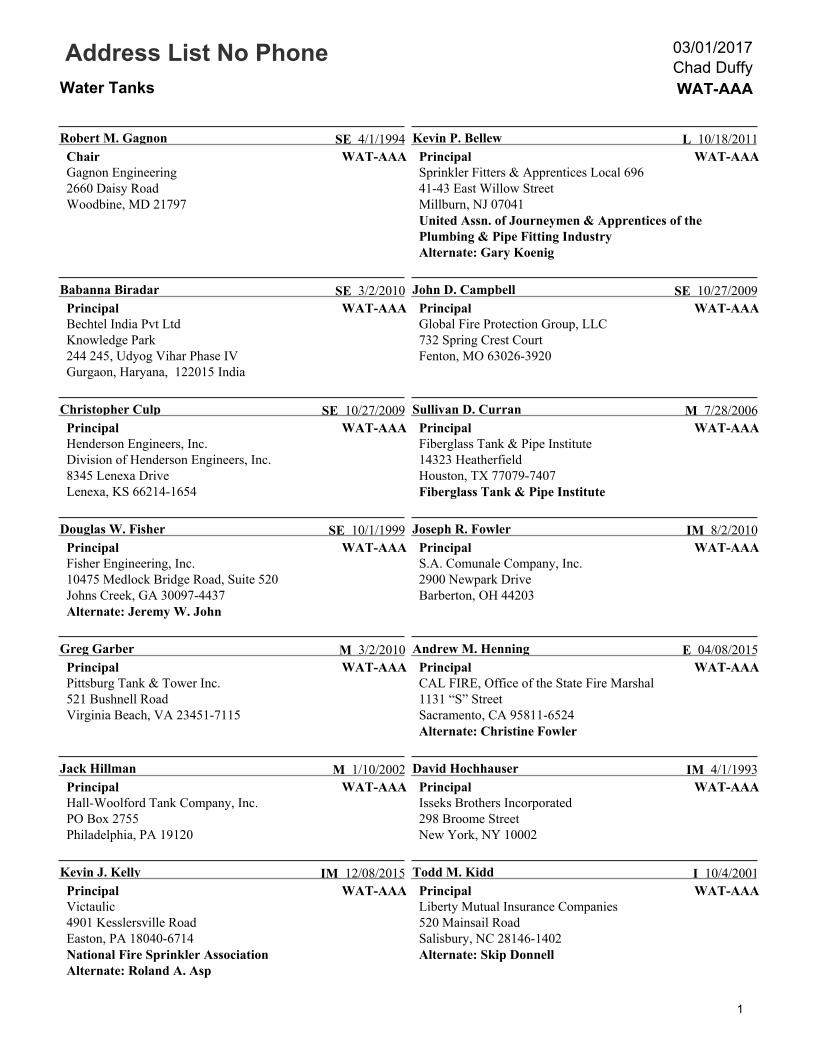
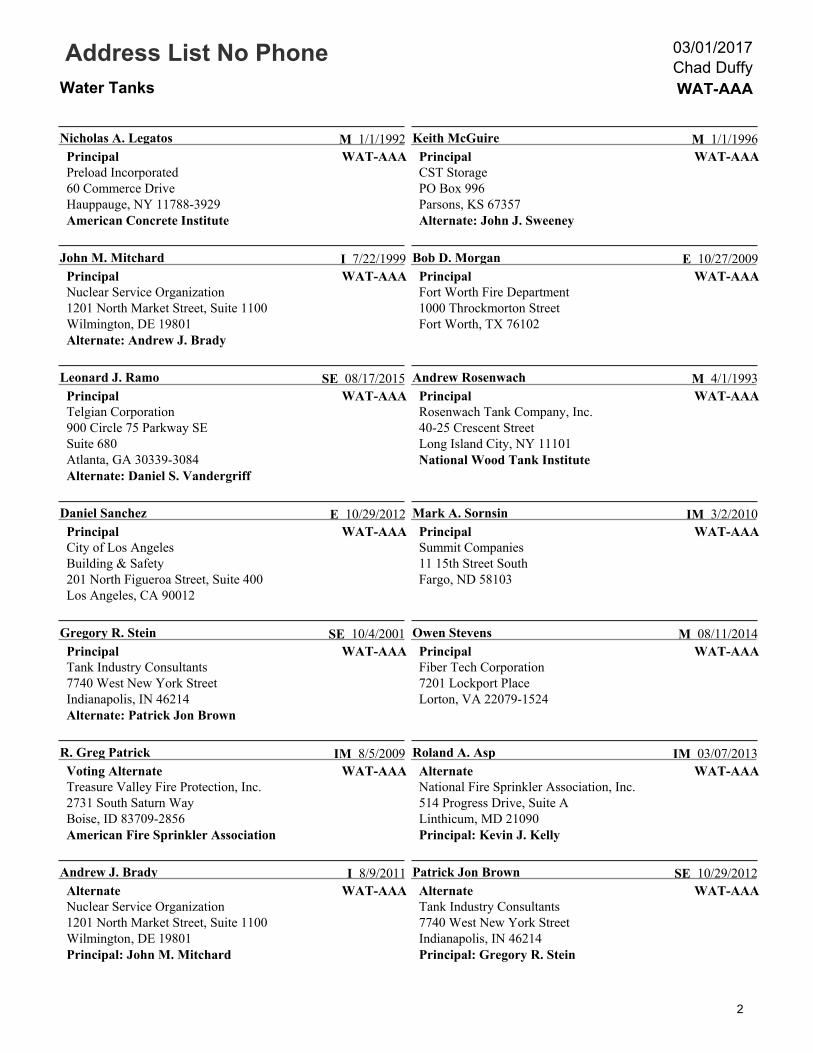

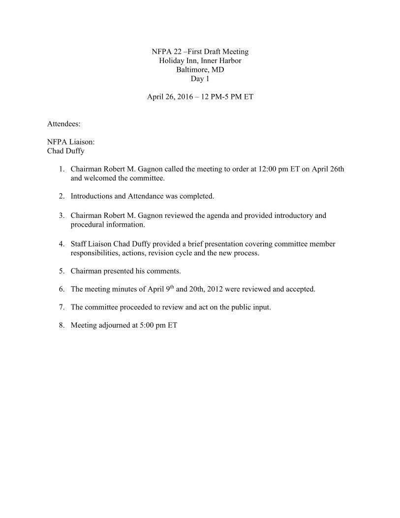

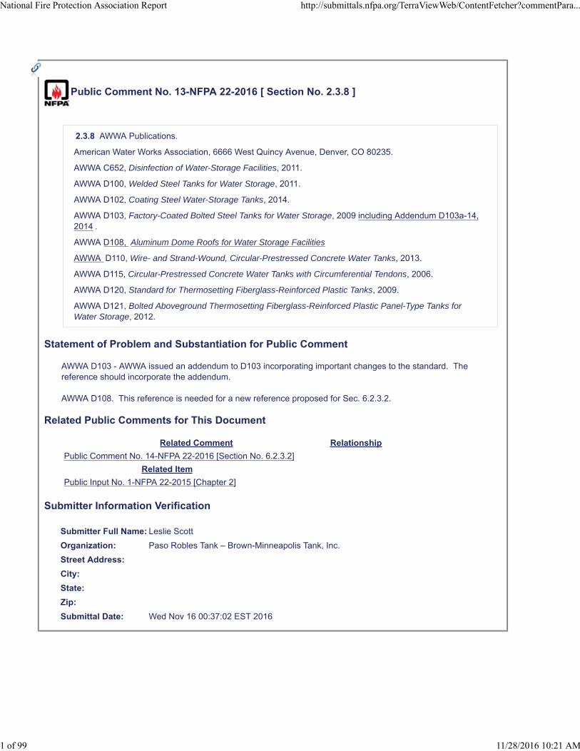
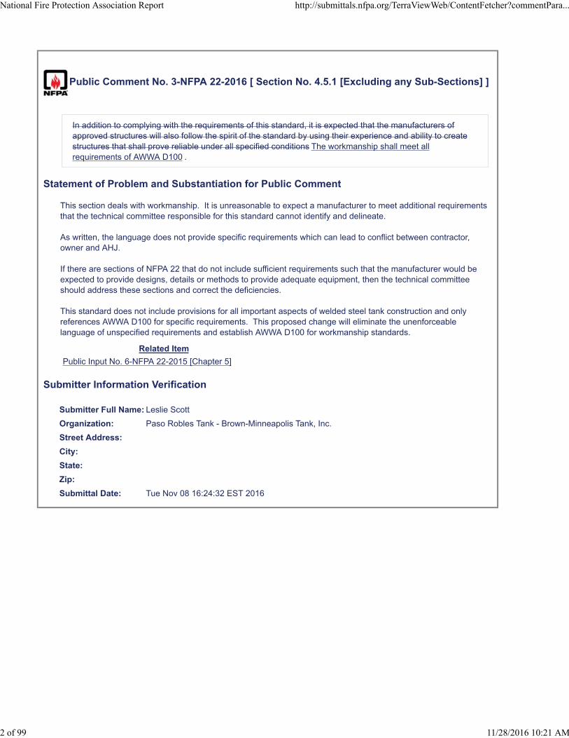
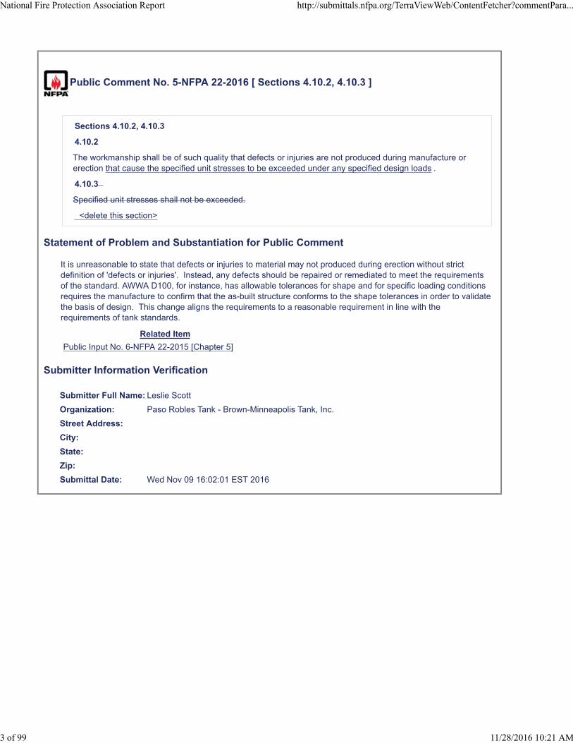
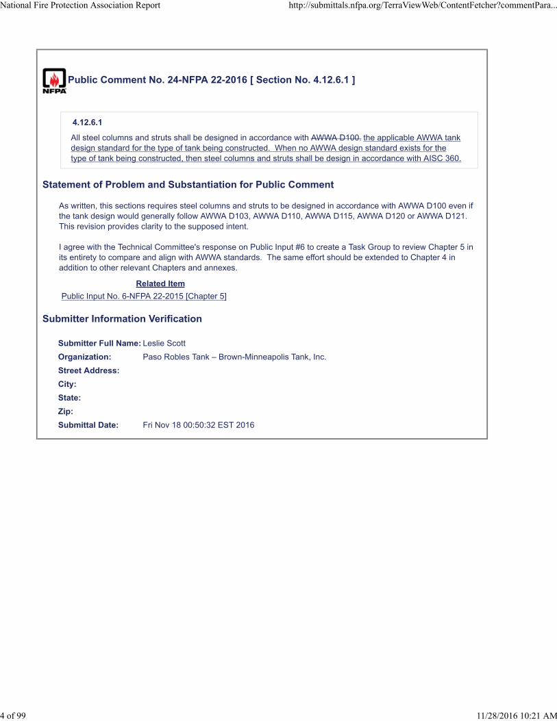
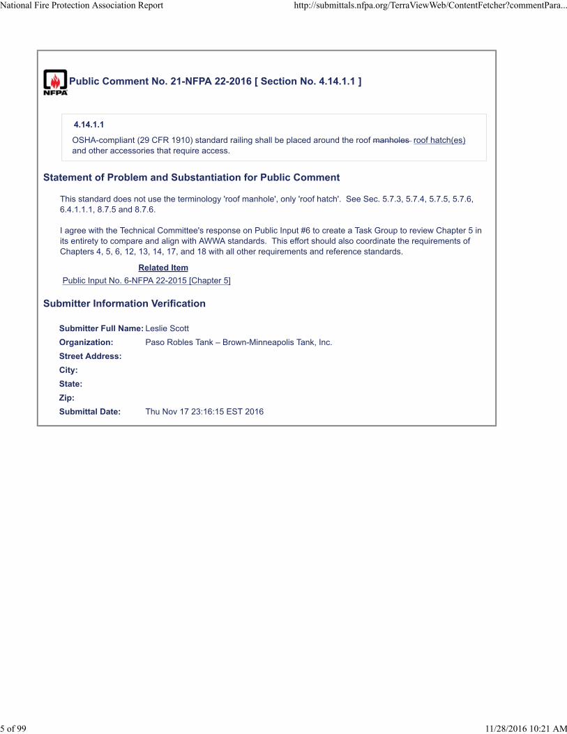
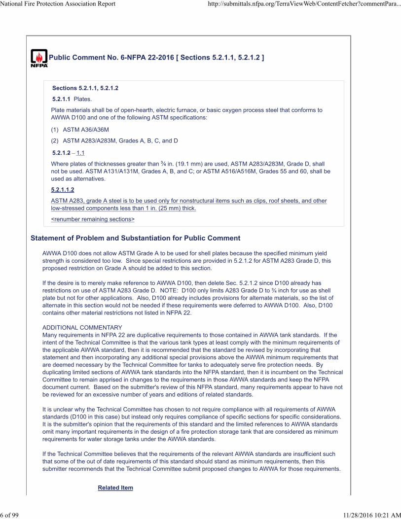

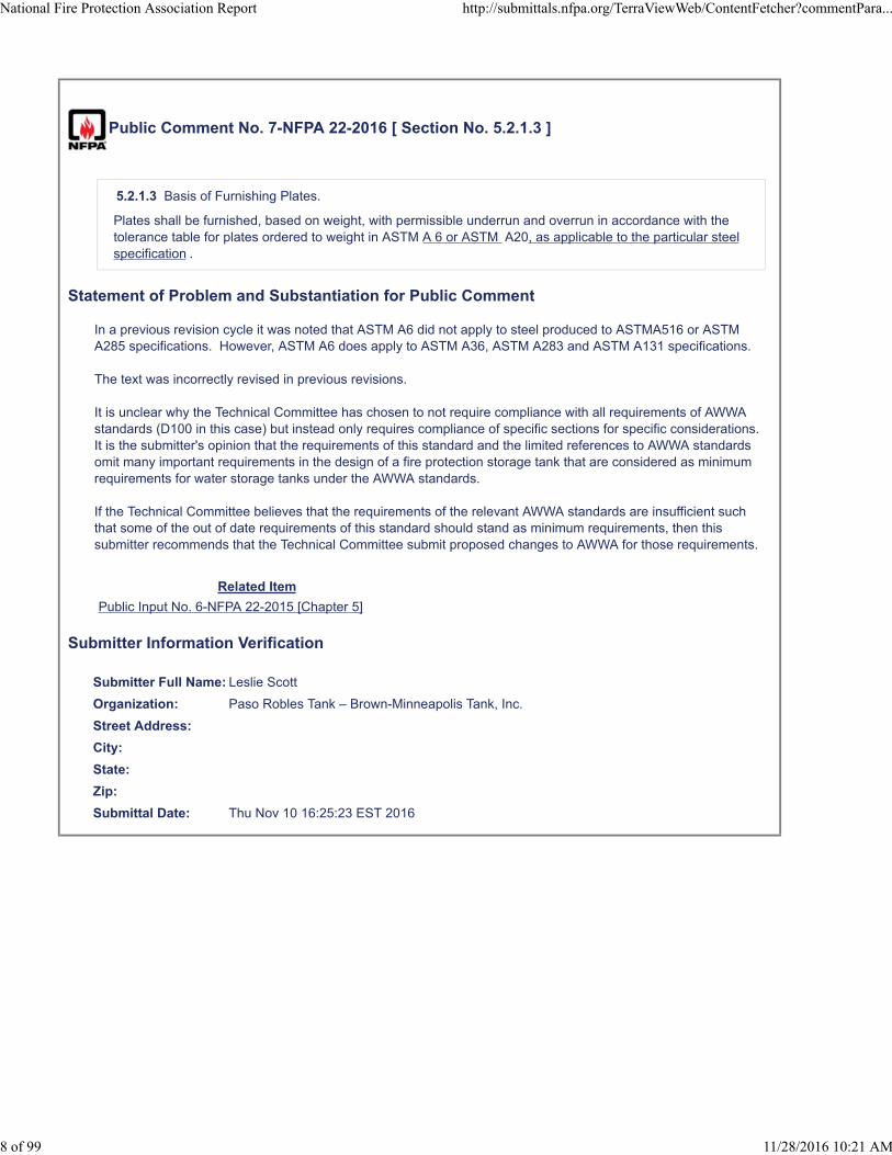
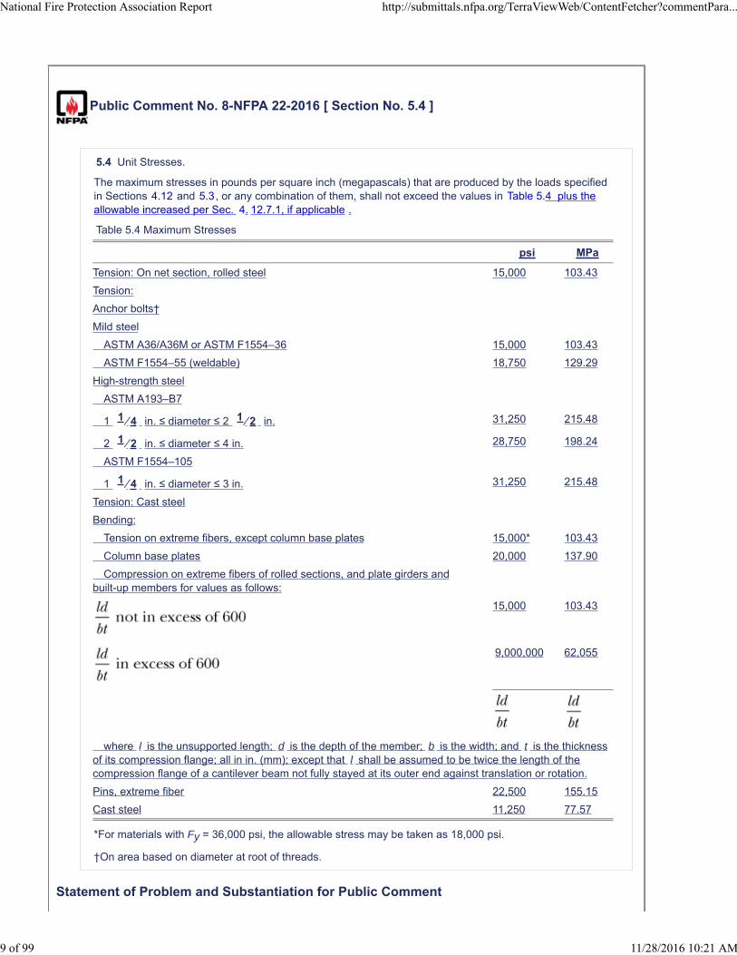


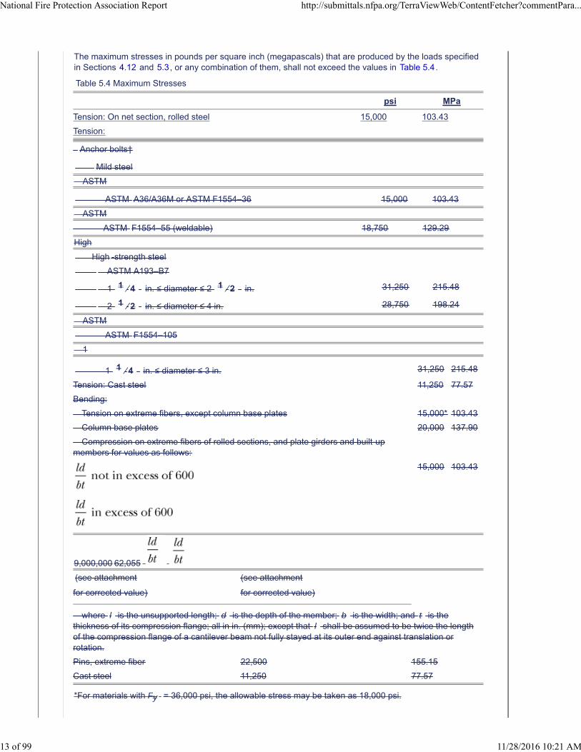
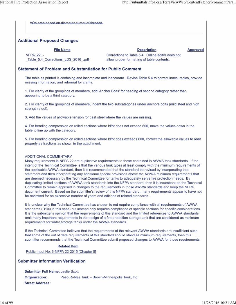

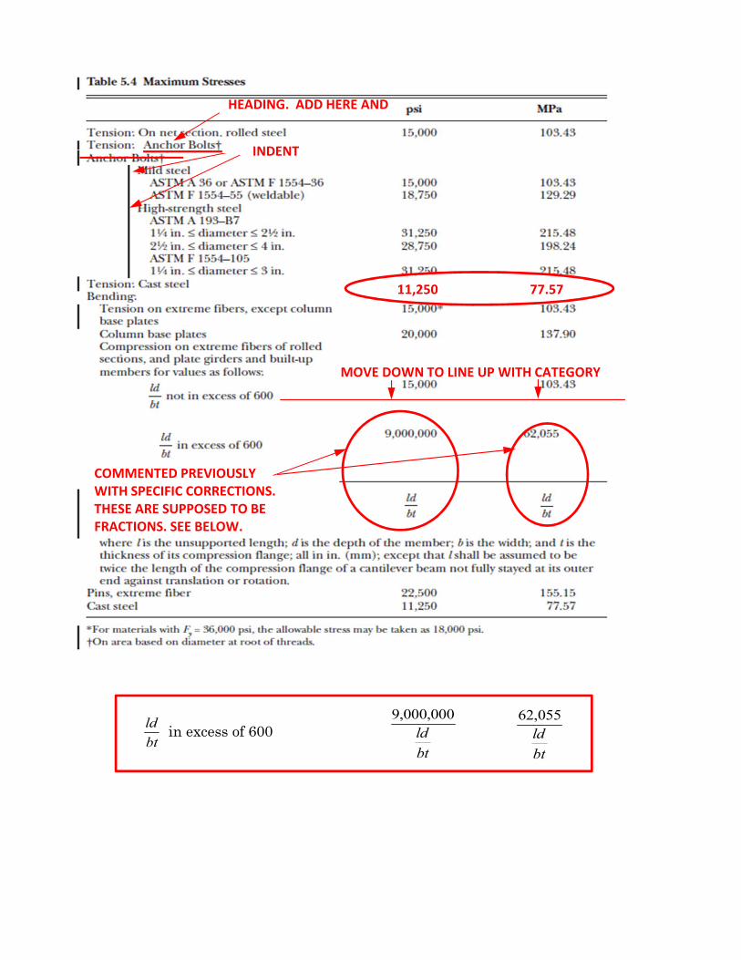
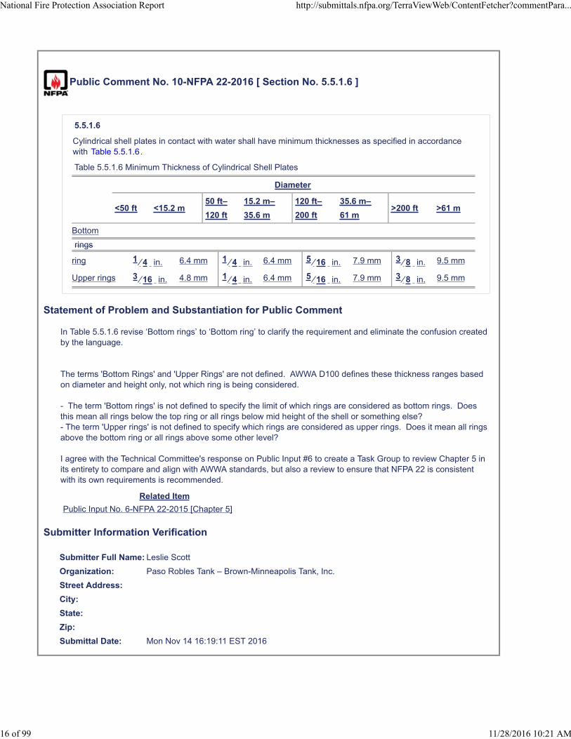
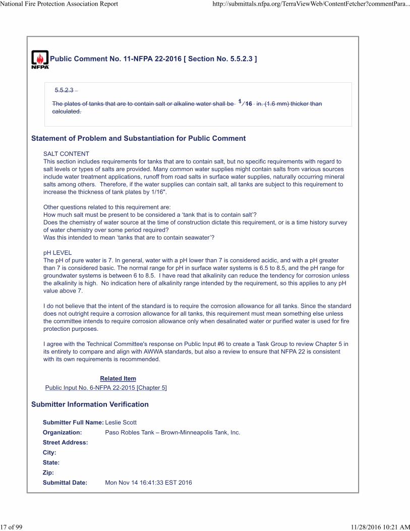
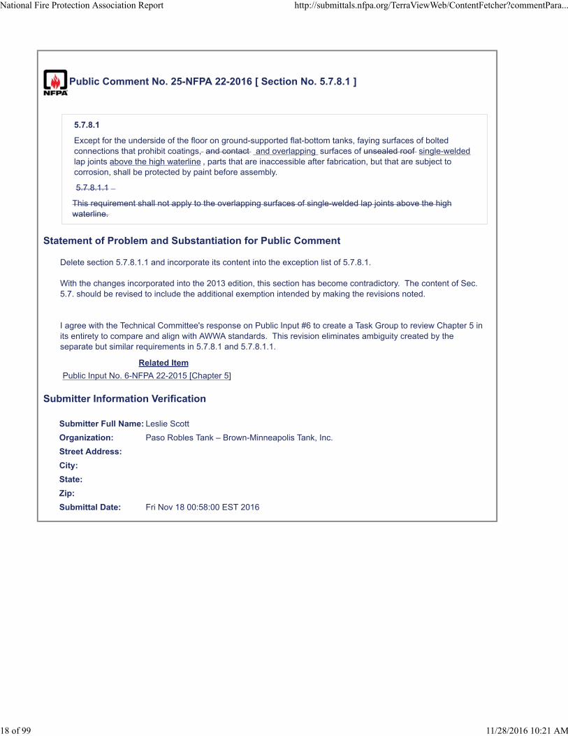
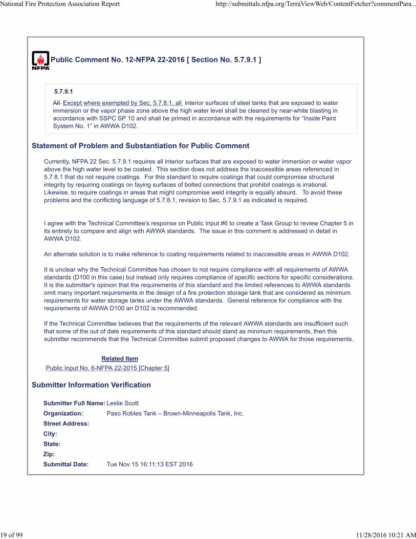


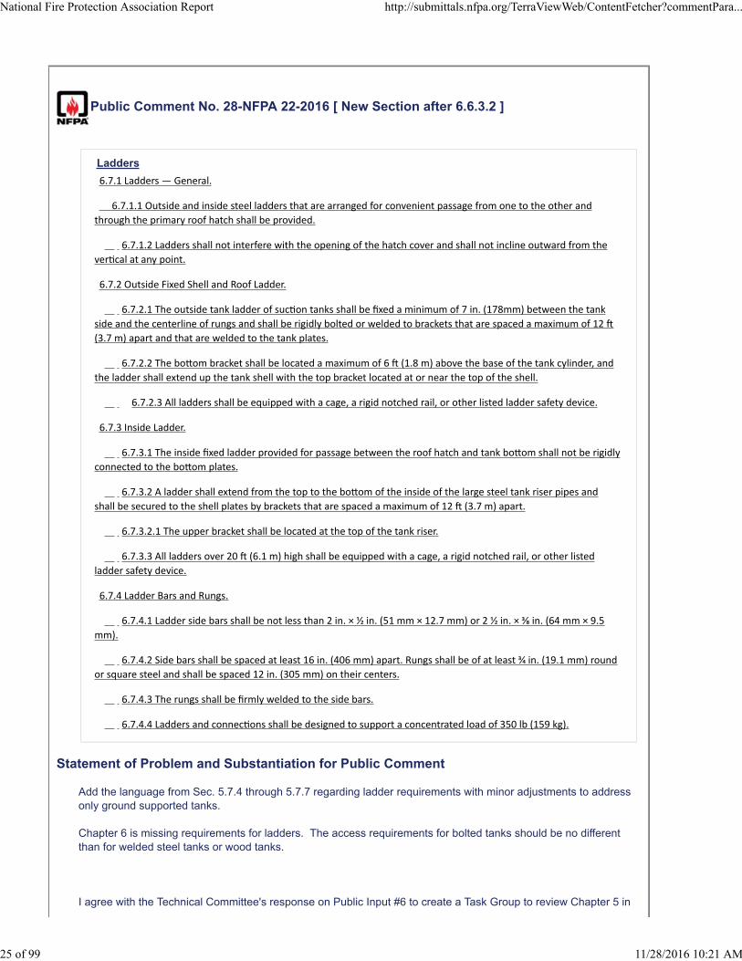


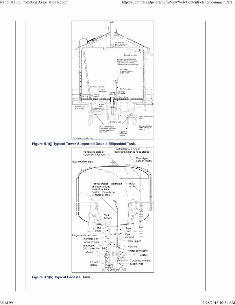


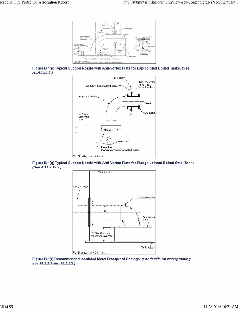
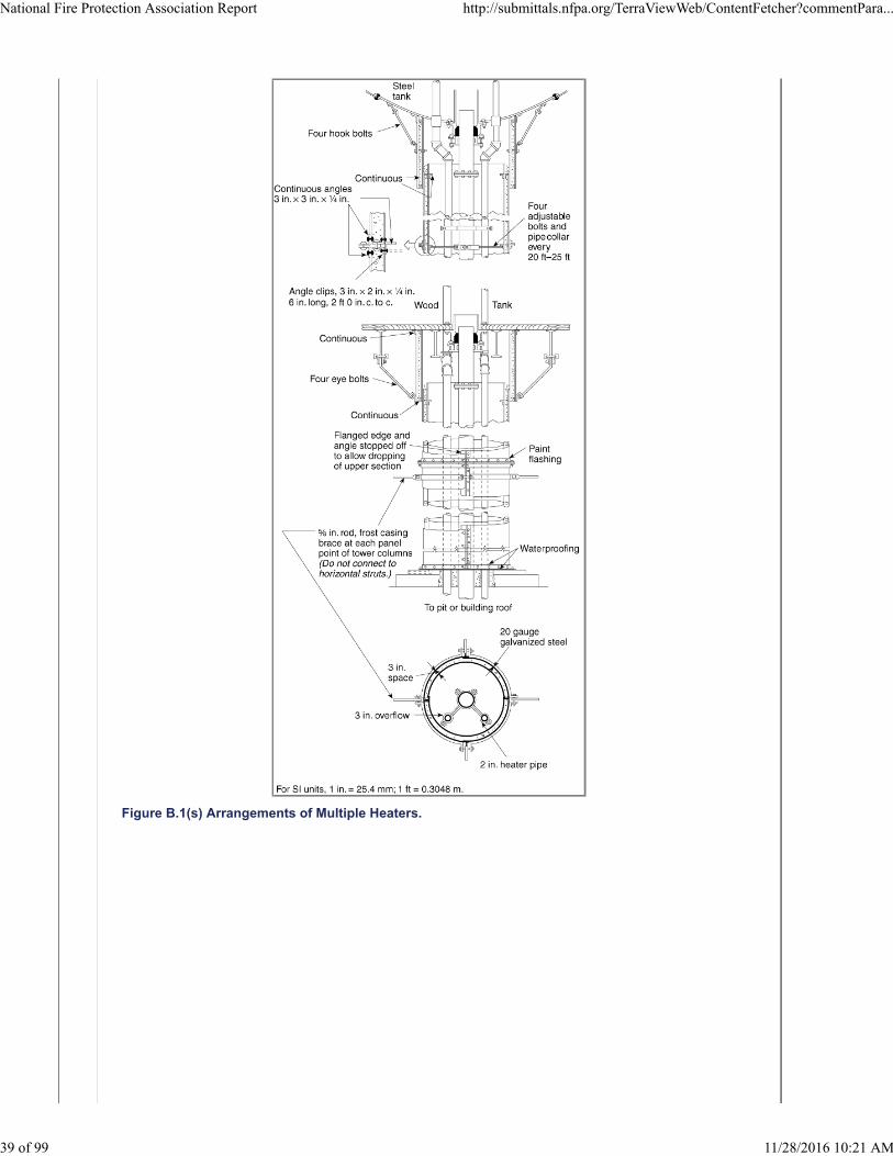

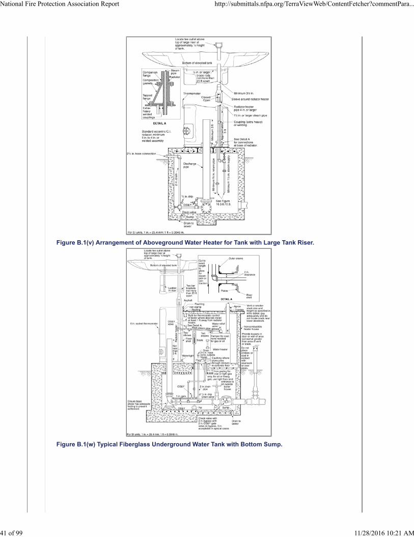
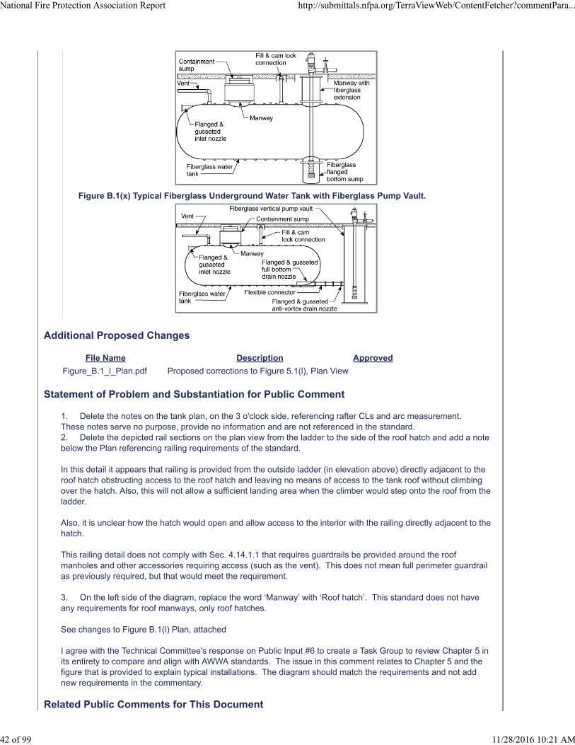
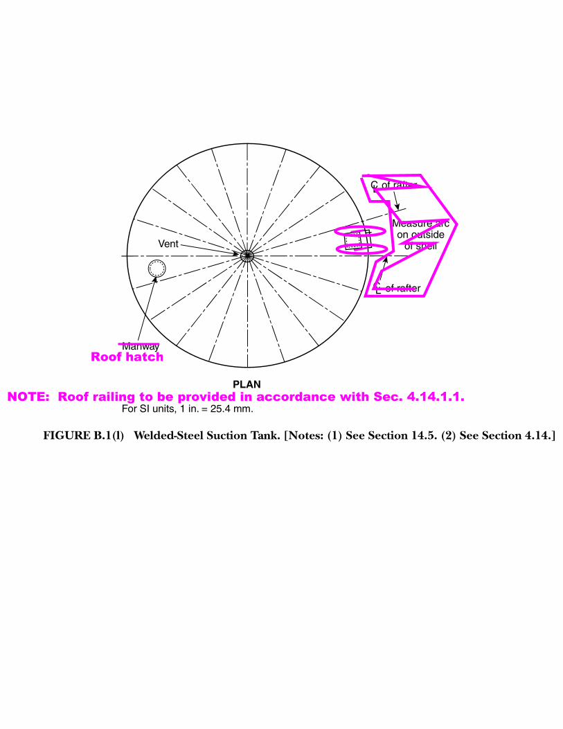


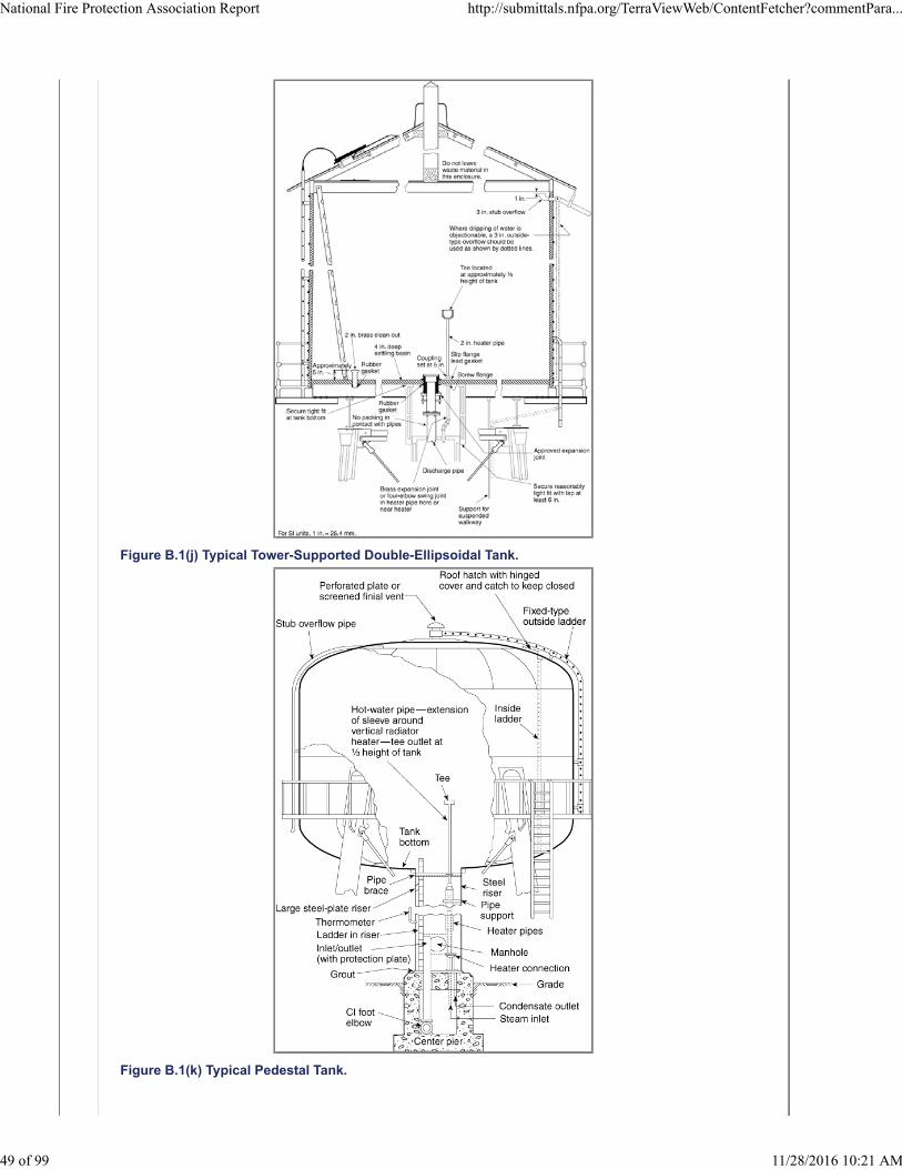

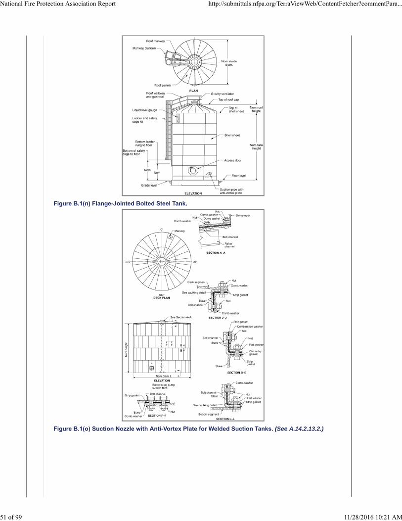
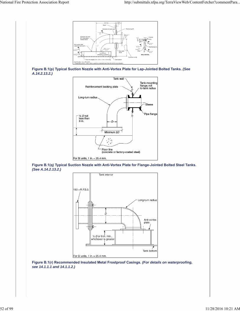


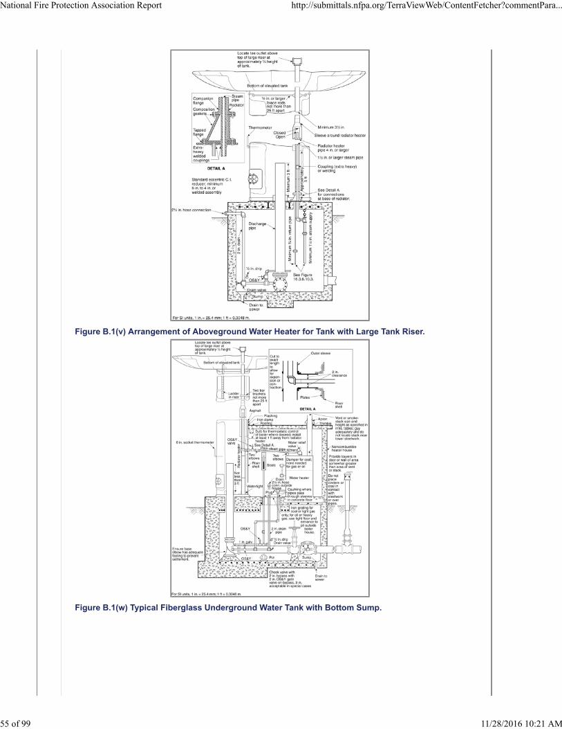
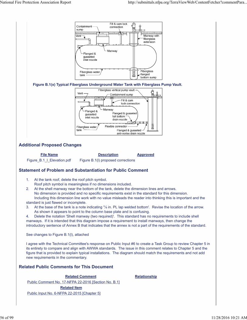


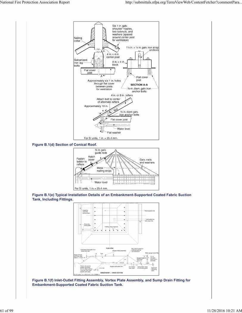
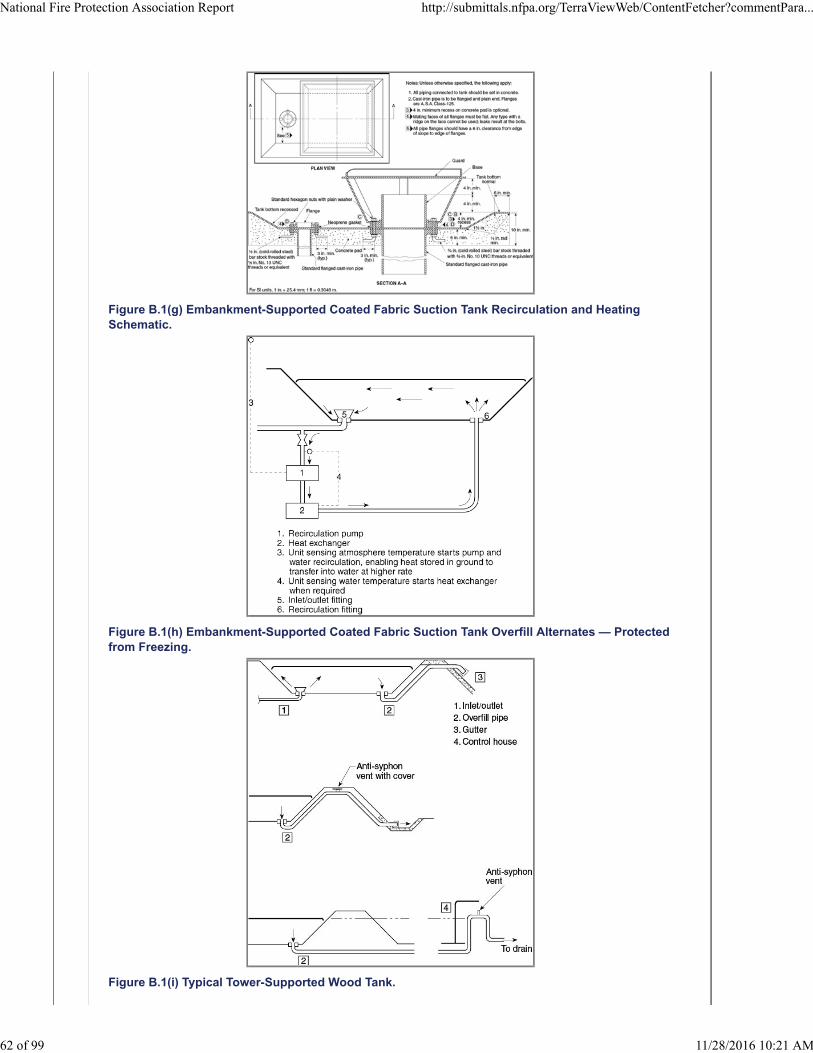


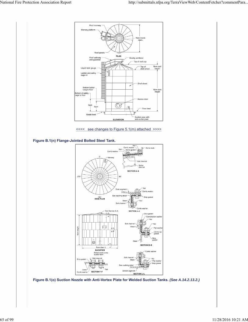


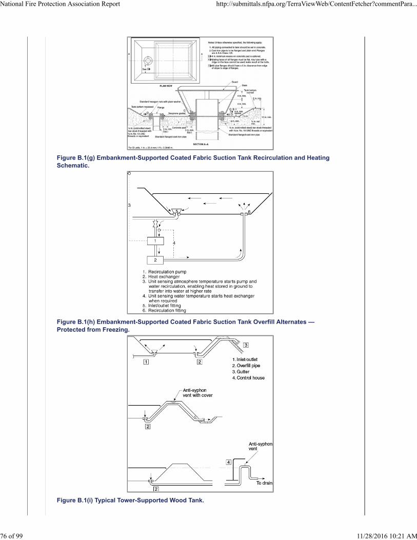

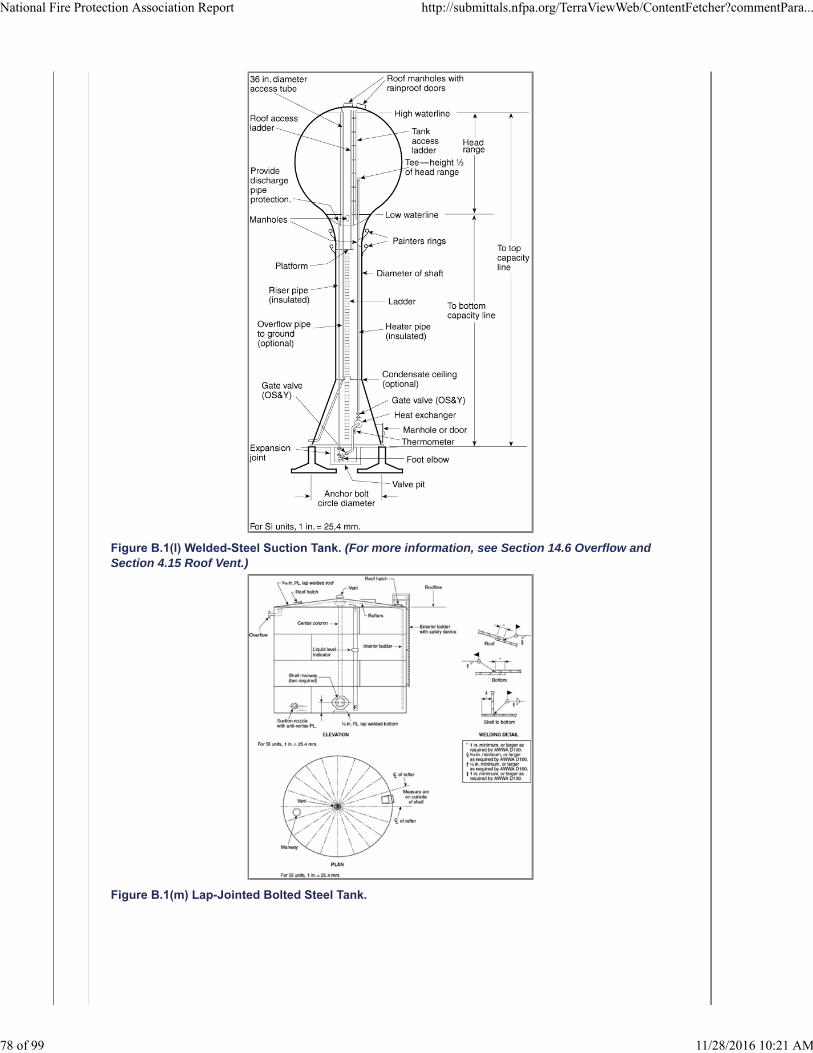


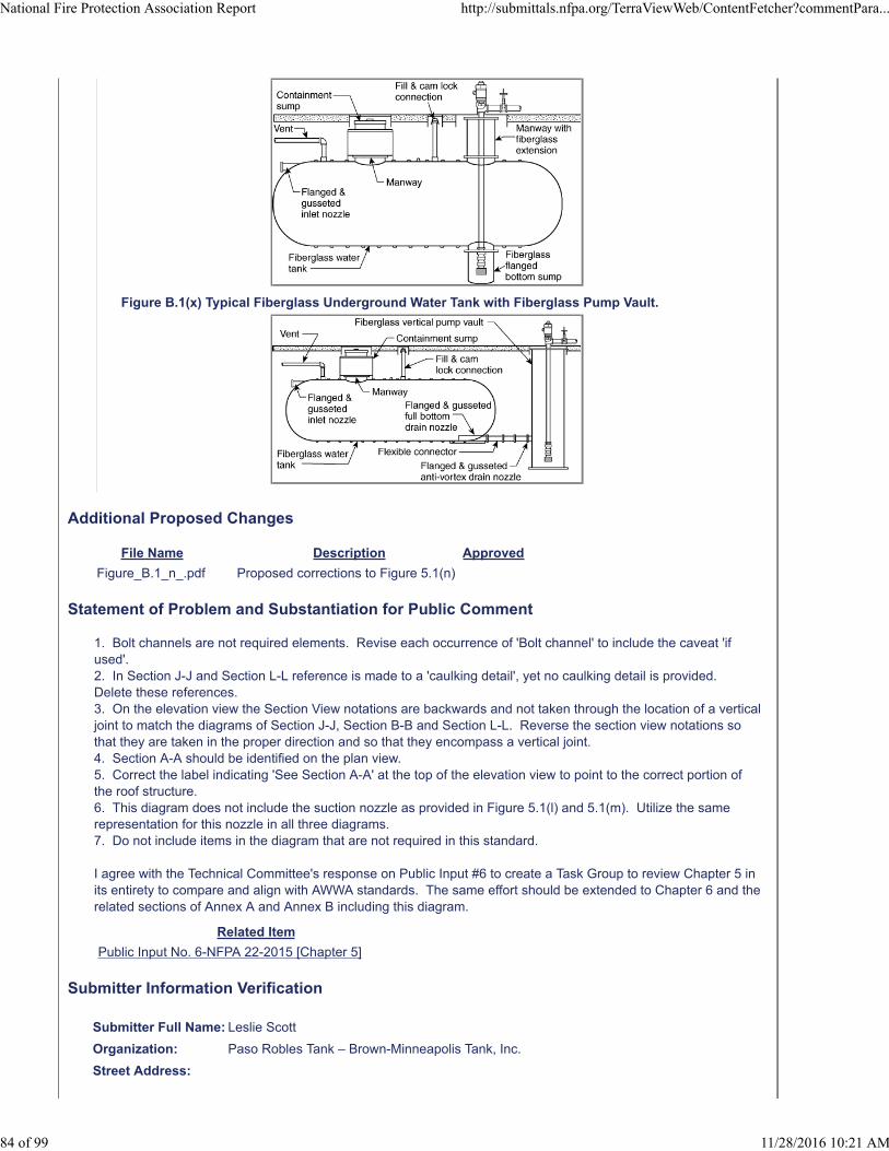

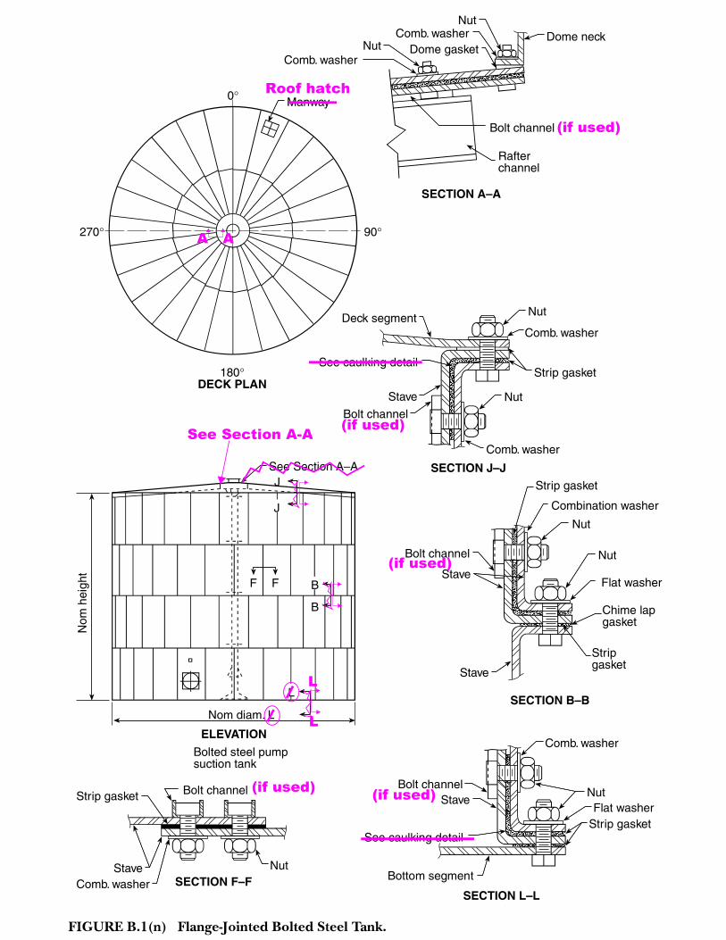


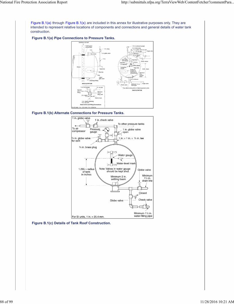
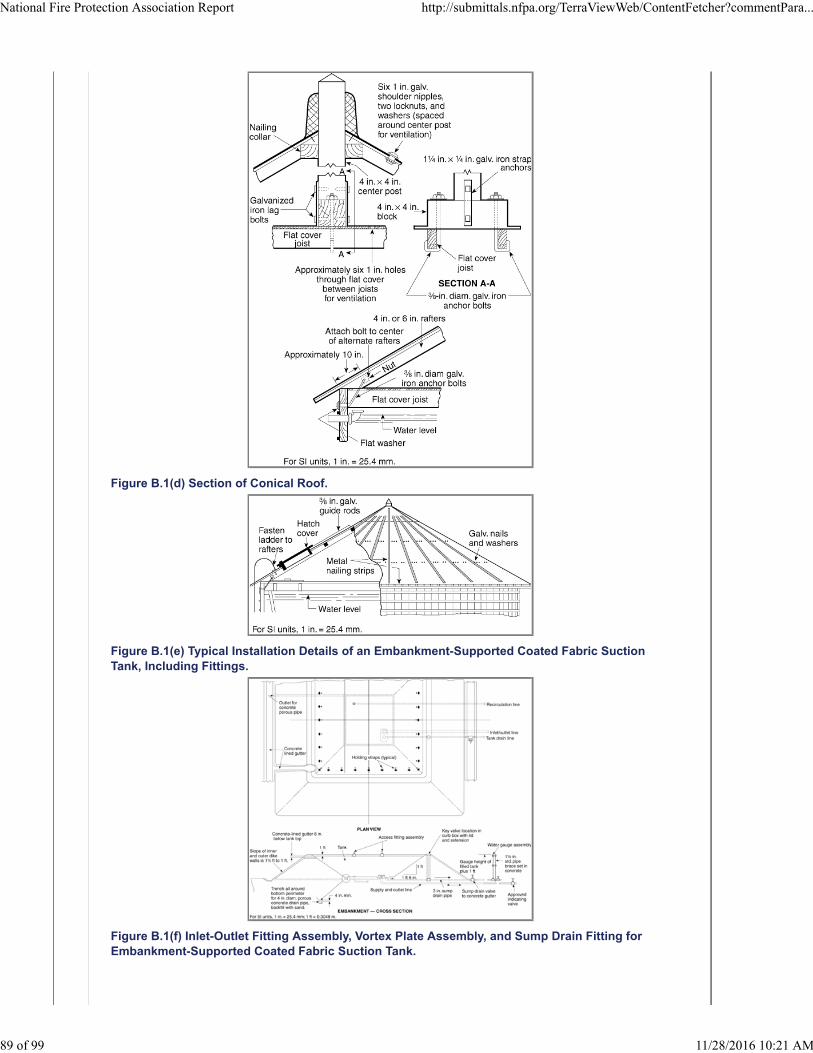
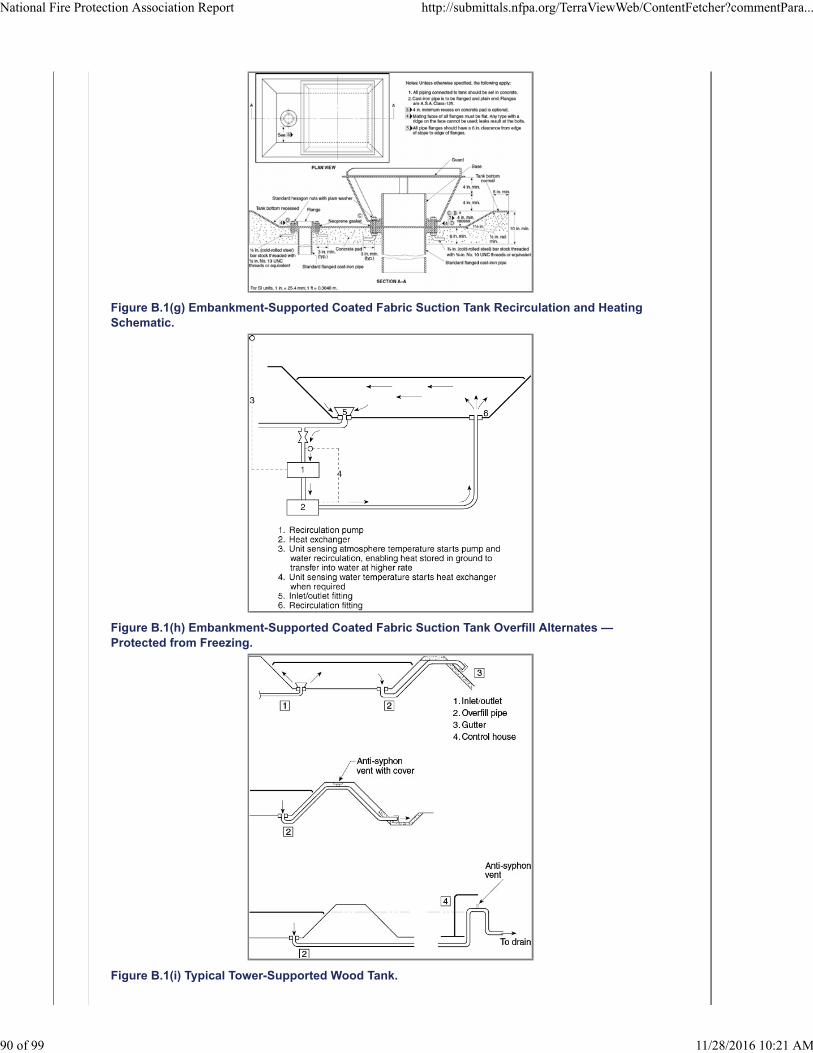


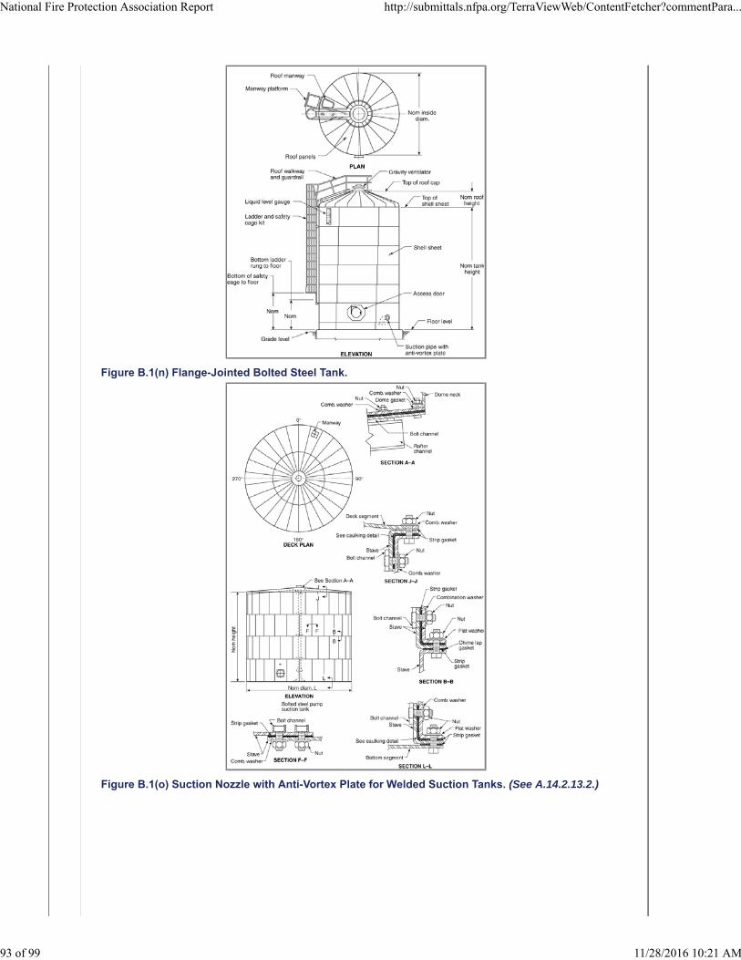


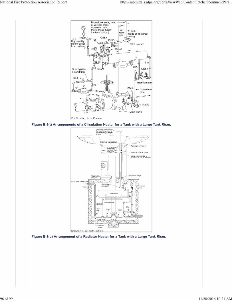

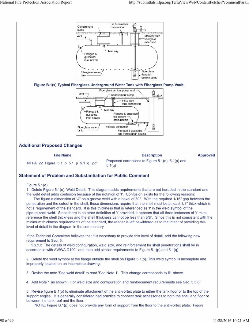

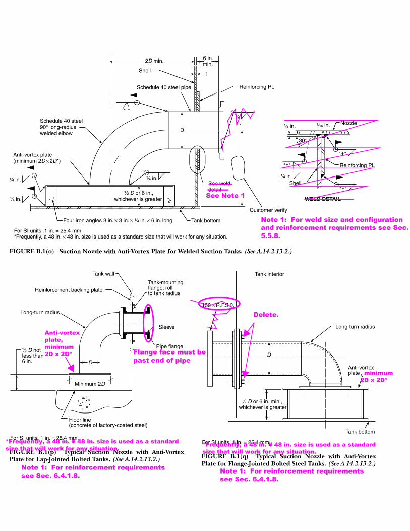


![arranged by tom wallace percussion by tony mccutchen 11 a a 10 aaa > e] aa aaa 6 aaa aaa aaa aaa aaa aaa 13 > 19 — 18 15 a a aa 16 a a 12 20 23 a > 24 aaa > 25 a > 26 aaa > 27 gÆ4k](https://static.documents.pub/doc/80x56/5e6c4dfc8bd84b079d5a5076/arranged-by-tom-wallace-percussion-by-tony-mccutchen-11-a-a-10-aaa-e-aa-aaa.jpg)


