Technical Data2500 Series
2506C-E15TAG12506C-E15TAG2
Diesel Engine - ElectropaK
Basic technical dataNumber of cylinders . ... ... ... ... ... ... ... ... ... ... ... ... ... ... ... ... ... ... ... ... ... 6 Cylinder arrangement ... ... ... ... ... ... ... ... ... ... ... ... ... ... ... . Vertical, In-lineCycle ... ... ... ... ... ... ... ... ... ... ... ... ... ... ... ... ... ... ... ... ... ... ... ... 4 strokeInduction system .. ... ... ... ... ... ... ... turbocharged, air to air charge coolingCombustion system.. ... ... ... ... ... ... ... ... ... ... ... ... ... ... ... . direct injectionCompression ratio ... ... ... ... ... ... ... ... ... ... ... ... ... ... ... ... ... ... ... ... .. 16:1Bore.. ... ... ... ... ... ... ... ... ... ... ... ... ... ... ... ... ... ... ... ... ... ... ... ... 137 mmStroke ... ... ... ... ... ... ... ... ... ... ... ... ... ... ... ... ... ... ... ... ... ... ... ... 171 mmCubic capacity .. ... ... ... ... ... ... ... ... ... ... ... ... ... ... ... ... ... ... ... ... 15 litresDirection of rotation .. ... ... ... ... ... ... ... ... anti-clockwise viewed on flywheelFiring order (cylinder 1 furthest from flywheel) . ... ... ... ... ... ... 1, 5, 3, 6, 2, 4
Total weight of ElectropaK-dry (engine only) . ... ... ... ... ... ... ... ... ... ... ... ... ... ... ... ... ... ... ... 1633 kg-wet... ... ... ... ... ... ... ... ... ... ... ... ... ... ... ... ... ... ... ... ... ... ... ... ... 1714 kg
Overall dimensions-height .. ... ... ... ... ... ... ... ... ... ... ... ... ... ... ... ... ... ... ... ... ... ... . 1718 mm-length .. ... ... ... ... ... ... ... ... ... ... ... ... ... ... ... ... ... ... ... ... ... ... . 2657 mm-width ... ... ... ... ... ... ... ... ... ... ... ... ... ... ... ... ... ... ... ... ... ... ... . 1120 mm
Moments of inertia (mk²)Engine-1500 rev/min ... ... ... ... ... ... ... ... ... ... ... ... ... ... ... ... ... ... ... . 2·3291 kgm²-1800 rev/min ... ... ... ... ... ... ... ... ... ... ... ... ... ... ... ... ... ... ... . 2·3291 kgm²Flywheel-1500 rev/min ... ... ... ... ... ... ... ... ... ... ... ... ... ... ... ... ... ... ... 1·96355 kgm²-1800 rev/min ... ... ... ... ... ... ... ... ... ... ... ... ... ... ... ... ... ... ... 1·96355 kgm²
PerformanceNote: All data based on operation to ISO 3046/1, BS5514 and DIN 6271 standard reference conditions.
Cyclic irregularityEngine / Flywheel maximum:-1500 rev/min. ... ... ... ... ... ... ... ... ... ... ... ... ... ... ... ... ... ... ... ... ... ... 1:44-1800 rev/min. ... ... ... ... ... ... ... ... ... ... ... ... ... ... ... ... ... ... ... ... ... ... 1:60
RatingsSteady state stability at constant speed ... ... ... ... ... ... ... ... ... ... . ± 0·25 %Electrical ratings are based on average alternator efficiency and are for guidance only (0.8 power factor being used)
Operating pointEngine speed ... ... ... ... ... ... ... ... ... ... ... ... ... ... ... . 1500 & 1800 rev/minCooling water maximum exit temperature . ... ... ... ... ... ... ... ... ... ..< 107 °C
Fuel dataTo conform to ... ... ... ... ... ... ... ... ... ... ... . BS2869 class A2 or BS EN590
Test conditions-air temperature . ... ... ... ... ... ... ... ... ... ... ... ... ... ... ... ... ... ... ... ... .. 25 °C-barometric pressure . ... ... ... ... ... ... ... ... ... ... ... ... ... ... ... ... ... .. 100 kPa-relative humidity ... ... ... ... ... ... ... ... ... ... ... ... ... ... ... ... ... ... ... ... ... 30%-air inlet restriction at maximum power (nominal) .. ... ... ... ... ... ... ... 2,5 kPa-exhaust back pressure at maximum power (nominal) .. ... ... ... ... ... 6,0 kPa-maximum fuel temperature (inlet pump)... ... ... ... ... ... ... ... ... ... ... .. 40 °CNote: If the engine is to operate in ambient conditions other than those of the test conditions, suitable adjustments must be made for these changes. For full details, contact Perkins Technical Service Department. For test conditions relevant to data on load acceptance, refer to the bottom of page 14.
Sound levelEstimated sound pressure level at 1 metre:-1500 rev/min. ... ... ... ... ... ... ... ... ... ... ... ... ... ... ... ... ... ... ... .103,1 dB(A)-1800 rev/min. ... ... ... ... ... ... ... ... ... ... ... ... ... ... ... ... ... ... ... .105,2 dB(A)
General installation
2506C-E15TAG1
2506C-E15TAG2
Rating definitions
Prime powerVariable load. Unlimited hours usage with an average load factor of 80% of the published Prime Power rating over each 24 hour period. A 10% overload is available for 1 hour in every 12 hours operation.
Standby powerVariable load. Limited to 500 hours annual usage up to 300 hours of which may be continuous running. No overload is permitted.
Emissions capabilityCertified against the requirements of EU2007 legislation for non-road mobile machinery, powered by constant speed engines (EU 97/68/EC Stage II). These engines also comply with the 1/2 TA Luft (1986) NOx limits of 2000 mg/nm³
Designation UnitsType of operation and application
Prime Standby Prime Standby50 Hz @ 1500 rev/min 60 Hz @ 1800 rev/min
Gross engine power kWb 412 451 458 514
Fan power kWm 8,8 15,5
Restriction losses kWm 7,2 7,8 8,0 8,8
ElectropaK nett engine power kWm 396 435 435 490
Gross brake mean effective pressure kPa 2197 2405 2036 2284
Combustion air flow m³/min 33,0 35,8 34,3 38,0
Exhaust gas temperature (max) °C N/A 550 N/A 550
Exhaust gas flow m³/min 85,0 94,0 96,0 105,3
Boost pressure ratio - 3,20 3,40 3,00 3,25
Overall thermal efficiency (nett) % 39,9 39,7 44,0 43,4
Friction and pumping power losses kWm 45 51
Mean piston speed m/s 8 10
Engine coolant flow l/sec 6,1 7,2
Cooling fan air flow (zero duct allowance) m³/min 722 866
Typical Gen Set electrical output (0.8 pf)kWe 364 400 400 450
kVA 455 500 500 563
Assumed alternator efficiency % 92 92
Designation UnitsType of operation and application
Prime Standby Prime Standby50 Hz @ 1500 rev/min 60 Hz @ 1800 rev/min
Gross engine power kWb 451 495 458 514
Fan power kWm 8,8 15,5
Restriction losses kWm 7,8 8,4 8,0 8,8
ElectropaK nett engine power kWm 435 478 435 490
Gross brake mean effective pressure kPa 2405 2640 2036 2284
Combustion air flow m³/min 35,8 36,6 34,3 38,0
Exhaust gas temperature (max) °C N/A 550 N/A 550
Exhaust gas flow m³/min 94 98 96 105,3
Boost pressure ratio - 3,40 3,60 3,00 3,25
Overall thermal efficiency (nett) % 39,7 39,6 44,0 43,4
Friction and pumping power losses kWm 49 51
Mean piston speed m/s 8 10
Engine coolant flow l/sec 6,1 7,2
Cooling fan air flow (zero duct allowance) m³/min 722 866
Typical Gen Set electrical output (0.8 pf)kWe 400 440 400 450
kVA 500 550 500 563
Assumed alternator efficiency % 92 92
Energy balance
2506C-E15TAG1
2506C-E15TAG2
Designation UnitsType of operation and application
Prime Standby Prime Standby
50 Hz @ 1500 rev/min 60 Hz @ 1800 rev/minEnergy in fuel kWt 1033 1131 1045 1185Energy in power output (gross) kWb 412 451 458 514Energy to cooling fan and restrictions kWm 16 17 23,5 24,4Energy in power output (nett) kWm 396,0 434,4 435,0 490,0Energy to exhaust kWt 327 362 299 341Energy to coolant and oil kWt 163 175 150 172Energy to radiation kWt 32,2 36,2 29,5 34,5Energy to charge cooler kWt 90 98 93 108
Designation UnitsType of operation and application
Prime Standby Prime Standby50 Hz @ 1500 rev/min 60 Hz @ 1800 rev/min
Energy in fuel kWt 1131 1250 1045 1185Energy in power output (gross) kWb 451 495 458 514Energy to cooling fan and restrictions kWm 17 17,2 23,5 24,4Energy in power output (nett) kWm 434,4 478,0 435,0 490,0Energy to exhaust kWt 362 406 299 341Energy to coolant and oil kWt 175 185 150 172Energy to radiation kWt 36,2 40,2 29,5 34,5Energy to charge cooler kWt 98 115 93 108
2506C-E15TAG1 and 2506C-E15TAG2 - left side view
Note: This drawing is for reference only. For installation purposes, please refer to the relevant General Installation drawing (Z13579).
390
FUE
LIN
LET
255
FUE
LR
ETU
RN
262
519
595
329
FAN
GU
ARD
S R
EMO
VED
FOR
CLA
RIT
Y
AIR
CLE
AN
ER
EVA
CU
ATO
R
ECM
TYPE
: AD
EM4
HA
ND
PR
IMIN
GPU
MP
FUE
L R
ETU
RN
NO
. 6 P
OR
T - 9
/16-
18-2
B T
HD
FUE
L IN
LET
NO
. 8 P
OR
T - 3
/4-1
6-2B
TH
D
FUE
L FI
LTE
R S
EC
ON
DA
RY
FUE
L FI
LTE
R P
RIM
AR
Y&
WA
TER
SEP
AR
ATO
R
RE
AR L
IFTI
NG
BR
ACK
ET
TAPP
ING
SIZ
E IN
ELB
OW
: 1/4
-18
NP
TF
AIR
INLE
T EL
BO
WM
ANIF
OLD
INC
OR
PO
RA
TED
INTO
HE
AD
.
CR
AN
KCAS
E B
REA
THE
RC
ON
NEC
TIO
N S
IZE
: Ø 4
4.45
(1.7
5")
SUM
P D
RA
IN T
APP
ING
M30
x1.5
SU
MP
DR
AIN
TA
PPIN
GM
24x1
.5LI
FT P
UM
P
FAN
T.V
. DAM
PER
Ø 4
50
2506C-E15TAG1 and 2506C-E15TAG2 - front view
Note: This drawing is for reference only. For installation purposes, please refer to the relevant General Installation drawing (Z13579).
560
1120
483
THK8
1718
283
4 PITCHES@ 277.5= 1110
532
1064
ENGINE DRIVEN FAN.Ø 9279 BLADE PLASTIC.
RADIATOR CORE & MESHREMOVED FOR CLARITY
10 - M8 X 1.25 WELD NUTS
2506C-E15TAG1 and 2506C-E15TAG2 - right side view
Note: This drawing is for reference only. For installation purposes, please refer to the relevant General Installation drawing (Z13579).
12
648
699
885
763
15°
448
392
417
Ø 2
03
10
()
51
CR
AN
KS
HAF
T
REAR FACEOF BLOCK
EXH
AU
ST
OU
TLET
ELB
OW
. SY
STE
M P
IPEW
OR
KM
US
T B
E A
DE
QU
ATE
LY S
UPP
OR
TED
TO
EN
SU
RE
THA
T N
O L
OA
D IS
EXE
RTE
D O
N E
LBO
W T
UR
BO
CH
AR
GE
R
EX
HA
US
T M
ANIF
OLD
TUR
BO
CH
AR
GE
R
OIL
FIL
LER
THE
RM
OST
AT
HO
USI
NG
TEM
PE
RA
TUR
E S
END
ERTA
PP
ING
SIZ
E:1/
2-14
-NPT
F TH
D
WAT
ER
PU
MP
DIP
STI
CK
OIL
PR
ES
SUR
E TA
PPIN
GS
IZE:
NO
.6 P
OR
T9/
16-1
8-2B
12.
7 D
EE
PO
IL F
ILTE
RO
IL C
OO
LER
OIL
SAM
PLE
VAL
VE
FRO
NT
LIFT
ING
BRA
CK
ET
2506C-E15TAG1 and 2506C-E15TAG2 - rear view
Note: This drawing is for reference only. For installation purposes, please refer to the relevant General Installation drawing (Z13579).
B
B
375
431.8
375
165.1
12 HOLESM12 X 1.75 X 21.5 DPON 619.12 PCD
8 HOLES1/2"-13-UNC X 24 DP
ON 438.17 PCD
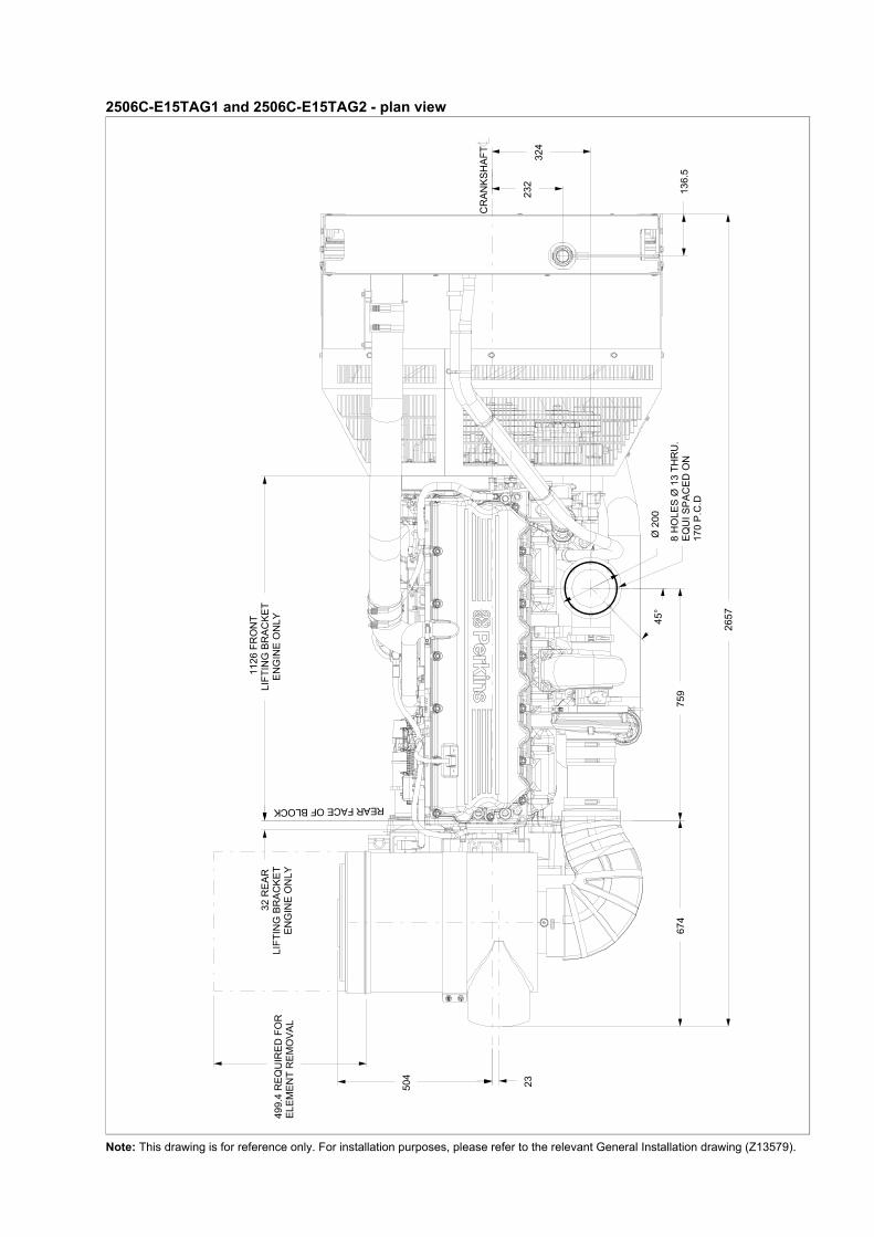
2506C-E15TAG1 and 2506C-E15TAG2 - plan view
Note: This drawing is for reference only. For installation purposes, please refer to the relevant General Installation drawing (Z13579).
ELEM
ENT
REM
OVA
L49
9.4
REQ
UIR
ED
FO
R 3
2 R
EA
R
LIFT
ING
BR
AC
KET
EN
GIN
E O
NLY
112
6 FR
ON
TLI
FTIN
G B
RAC
KET
EN
GIN
E O
NLY
23
674
759
504
45°
324
Ø 2
00
232
136.
5
REAR FACE OF BLOCK
CR
ANK
SHAF
T
8 H
OLE
S Ø
13
THR
U.
EQ
UI S
PAC
ED O
N17
0 P
.C.D
2657
2506C-E15TAG1 and 2506C-E15TAG2 - miscellaneous views
Note: This drawing is for reference only. For installation purposes, please refer to the relevant General Installation drawing (Z13579).
54
TO
CRANKSHAFT
625
TO CRANKSHAFT
31R21
SCRAP VIEW SHOWING
SCRAP VIEW SHOWING ALTERNATOR CONNECTIONS.
GROUND (NEG)1/4" UNC X 20 TPITIGHTEN TO 6 Nm.
BATTERY (POS)M6 X 1TIGHTEN TO11.3 Nm NOM
INDICATOR LIGHTM4 X 0.7TIGHTEN TO2.25 Nm NOM
RELAYM4 X 0.7TIGHTEN TO2.25 Nm NOM
53
TO CRANKSHAFT
674
TO CRANKSHAFT
62R20
SCRAP VIEW SHOWING
2425.4
Ø584.4584.2 Ø466.85
466.75 Ø409.8409.4
9.38.7
SECTION B-B
SCRAP VIEW SHOWING
GROUND (NEG)1/2" X 13 TPI
TIGHTEN TO 24 Nm.
BATTERY (POS)1/2" X 13 TPI
TIGHTEN TO 24 Nm.
SOLENOID (POS)No 10 X 32 TPITIGHTEN TO 2.5 Nm.
DETAILS OF REAR LIFTINGEYE
FAN GUARDS & THERMOSTAT REMOVED FOR CLARITY.SCALE 1:3
DETAILS OF FRONT LIFTINGEYE
DETAILS OF SAE 1 / 2 FLYWHEEL HOUSINGAND SAE J620 SIZE 14 FLYWHEEL
STARTER MOTOR CONNECTIONSSCALE 1:3
Cooling system
Recommended coolant: 50% inhibited ethylene glycol or 50% inhibited propylene glycol and 50% clean fresh water. Where there is no likelihood of ambient temperatures below 10 °C, clean ‘soft’ water may be used, treated with 1% by volume of Perkins inhibitor in the cooling system. The inhibitor is available from all Perkins Distributors.Total system coolant capacity ... ... ... ... ... ... ... ... ... ... . 58,0 litresMaximum pressure:-in crankcase water jacket. ... ... ... ... ... ... ... ... ... ... ... ... 276 kPaMaximum top tank temperature ... ... ... ... ... ... ... ... ... ... . 107 °CMaximum static pressure on pump ... ... ... ... ... ... ... ... ... 170 kPaMaximum permissible restriction:-to coolant pump flow ... ... ... ... ... ... ... ... ... ... ... ... ... ... .. 30 kPaTemperature rise across engine with inhibited coolant:-standby power @ 1500 and 1800 rev/min ... ... ... ... ... ... ... 10 °C-prime power @ 1500 and 1800 rev/min... ... ... ... ... ... ... ... . 9 °CThermostat operation range.. ... ... ... ... ... ... ... ... ... ... 88 to 98 °C
Radiator-face area .. ... ... ... ... ... ... ... ... ... ... ... ... ... ... ... ... ... ... 1·238 m²-weight (dry) .. ... ... ... ... ... ... ... ... ... ... ... ... ... ... ... ... ... .. 132 kg-rows and materials... ... ... ... ... ... ... ... ... ... ... 2 rows, Aluminium-matrix density and material .. ... ... ... .. 12 fins per inch, Aluminium-width of matrix.. ... ... ... ... ... ... ... ... ... ... ... ... ... ... ... .. 1048 mm-height of matrix ... ... ... ... ... ... ... ... ... ... ... ... ... ... ... .. 1100 mm-pressure cap setting (minimum)... ... ... ... ... ... ... ... ... ... .. 69 kPa
Charge cooler with integral radiator-face area .. ... ... ... ... ... ... ... ... ... ... ... ... ... ... ... ... ... ... 1·006 m²-number of rows and material ... ... ... ... ... ... ... ..1 row, Aluminium-matrix density and material .. ... ... ... 12,5 fins per inch, Aluminium-width of matrix.. ... ... ... ... ... ... ... ... ... ... ... ... ... ... ... ... 915 mm-height of matrix ... ... ... ... ... ... ... ... ... ... ... ... ... ... ... .. 1100 mm
Coolant pumpSpeed:-1500 rev/min ... ... ... ... ... ... ... ... ... ... ... ... ... ... ... 1622 rev/min-1800 rev/min ... ... ... ... ... ... ... ... ... ... ... ... ... ... ... 1946 rev/minMethod of drive . ... ... ... ... ... ... ... ... ... ... ... ... ... ... ... ... ... . gear
Fan-diameter ... ... ... ... ... ... ... ... ... ... ... ... ... ... ... ... ... ... ... 927 mm-drive ratio . ... ... ... ... ... ... ... ... ... ... ... ... ... ... ... ... ... ... .. 0·92:1-number of blades . ... ... ... ... ... ... ... ... ... ... ... ... ... ... ... ... ... .. 9-material ... ... ... ... B3WG6 or PA6GF30 Nylon 6 glass filled 30%-type .. ... ... ... ... ... ... ... ... ... ... ... ... ... ... ... ... ... ... ACS 367500
Cooling clearanceAmbient cooling clearance (standby power) based on air temperature at fan of 6 °C above the ambient
Electrical system
Type ... ... ... ... ... ... ... ... ... ... ... ... ... ... ... ... ..12V negative earthAlternator-type ... ... ... ... ... ... ... ... ... ... ... ... ... ... ... ... ... ... ... ... ... ... 22SI-voltage .. ... ... ... ... ... ... ... ... ... ... ... ... ... ... ... ... ... ... ... 24 volts-output ... ... ... ... ... ... ... ... ... ... ... ... ... ... ... ... ... ... ... .. 70 ampsStarter-type ... ... ... ... ... ... ... ... ... ... ... ... ... ... ... ... ... ... ... ... ... .. 42MT-motor voltage ... ... ... ... ... ... ... ... ... ... ... ... ... ... ... ... .. 24 volts-motor power . ... ... ... ... ... ... ... ... ... ... ... ... ... ... ... ... ... 7,5 kWNumber of teeth-on the flywheel . ... ... ... ... ... ... ... ... ... ... ... ... ... ... ... ... ... . 113-on starter pinion ... ... ... ... ... ... ... ... ... ... ... ... ... ... ... ... ... ... 11Minimum cranking speed ... ... ... ... ... ... ... ... ... ... ... 100 rev/minPull-in current of starter motor solenoid @ -25 °C max (1) ... ... ... ... ... ... ... ... ... ... ... ... ... ... ... . 57 ampsHold-in current of starter motor solenoid @ -25 °C max (1) ... ... ... ... ... ... ... ... ... ... ... ... ... ... ... .. 16 amps1. All leads to rated at 10 amps minimum
2506C-E15TAG1 maximum additional restriction (duct allowance) to cooling airflow and resultant minimum airflowDuct allowance with inhibited coolant at 50 °C
Description rev/min Units Standby
Duct allowance1500 kPa 0·1251800 kPa 0·125
Minimum airflow1500 m³/min 6601800 m³/min 822
Duct allowance with 50% glycol at 43 °C
Duct allowance1500 kPa 0·2001800 kPa 0·200
Minimum airflow1500 m³/min 5761800 m³/min 792
2506C-E15TAG2 maximum additional restriction (duct allowance) to cooling airflow and resultant minimum airflowDuct allowance with inhibited coolant at 50 °C
Description rev/min Units Standby
Duct allowance1500 kPa 0·1251800 kPa 0·125
Minimum airflow1500 m³/min 6601800 m³/min 822
Duct allowance with 50% glycol at 43 °C
Duct allowance1500 kPa 0·2001800 kPa 0·200
Minimum airflow1500 m³/min 5761800 m³/min 822
Cold start recommendations
Battery capacity is defined by the 20 hour rateThe oil specification should be for the minimum ambient temperature as the oil will not be warmed by the immersion heaterBreakaway current is dependent on battery capacity available. Cables should be capable of handling the transient current which may be up to double the steady cranking current.
Exhaust system
Maximum back pressure ... ... ... ... ... ... ... ... ... ... ... ... ... 6,8 kPaExhaust outlet size (internal).. ... ... ... ... ... ... ... ... ... ... ... 127 mm
Recommended exhaust pipe diameter
Fuel system
Type of injection .. ... ... ... ... ... ... ... ... ... ... ... ... ... ... ... ... . MEUIInjector type. ... ... ... ... ... ... ... ... ... ... ... ... ... ... ... ... ... ... . MEUIInjector pressure.. ... ... ... ... ... ... ... ... ... ... ... ... ... ... ... 200 MPa
Fuel lift pumptype.. ... ... ... ... ... ... ... ... ... ... ... ... ... ... ... ... ... ... ... gear drivenDelivery flow:-1500 rev/min .. ... ... ... ... ... ... ... ... ... ... ... ... ... ... ... 413 litres/hr-1800 rev/min .. ... ... ... ... ... ... ... ... ... ... ... ... ... ... ... 457 litres/hrPressure .. ... ... ... ... ... ... ... ... ... ... ... ... ... ... ... ... ... ... ..550 kPaMaximum suction head at pump inlet.. ... ... ... ... ... ... ... ... ... 3 mMaximum static pressure head ... ... ... ... ... ... ... ... ... ... ... ... 4 mFuel inlet temperature to be less than . ... ... ... ... ... ... ... ... ..55 °CGovernor type.. ... ... ... ... ... ... ... ... ... ... ... ... ... ... ... ... electronicGoverning to ... ... ... ... ... ... ... . ISO 8528-5 class G3 steady state
Fuel filtration level-primary ... ... ... ... ... ... ... ... ... ... ... ... ... ... ... ... ... ... ... ... 10 µm-secondary... ... ... ... ... ... ... ... ... ... ... ... ... ... ... ... ... ... ... .. 2 µm
Fuel consumption
2506C-E15TAG1
2506C-E15TAG2
Temperature Range
5 to -10 °C (41 to 14 °F)
Oil: 15W40Starter: 42MTBattery: 2x 12V 128 AhMax breakaway current: 1250 ampsCranking current: 676 ampsAids: NoneMinimum mean cranking speed: 120 rev/min
Temperature Range
-11 to -25 °C (12.2 to -13 °F)
Oil: 0W40Starter: 42MTBattery: 2x 12V 128 AhMax breakaway current: 1250 ampsCranking current: 880 ampsAids: block heater 1.5 kWMinimum mean cranking speed: 120 rev/min
length1500 rev/min 1800 rev/min
mm mmup to 10m 125 150
10m to 20m 150 15020m to 30m 150 200
Designation
Fuel consumption calculated on nett rated powers
g/kWh litres/hr1500
rev/min1800
rev/min1500
rev/min1800
rev/minStandby 217 201 109 114Prime + 10% 217 201 109 114Prime 216 199 99 100At 75% of Prime 212 204 73 77At 50% of Prime 222 217 51 57
Designation
Fuel consumption calculated on nett rated powers
g/kWh litres/hr1500
rev/min1800
rev/min1500
rev/min1800
rev/minStandby 207 201 114 114Prime + 10% 207 201 114 114Prime 211 199 106 100At 75% of Prime 215 204 81 77At 50% of Prime 220 217 55 55
Induction system
Maximum air intake restriction-clean filter. ... ... ... ... ... ... ... ... ... ... ... ... ... ... ... ... ... ... .3,7 kPa-dirty filter .. ... ... ... ... ... ... ... ... ... ... ... ... ... ... ... ... ... ... .6,2 kPa-air filter type . ... ... ... ... ... ... ... . paper element 457 mm diameter
Lubrication system
The recommended SAE viscosity is a multigrade oil (15W40) which adequately meets the specifications of API CI4Total system capacity ... ... ... ... ... ... ... ... ... ... ... ... ... . 62,0 litresMaximum sump capacity... ... ... ... ... ... ... ... ... ... ... ... . 53,0 litresMinimum sump capacity ... ... ... ... ... ... ... ... ... ... ... ... . 45,0 litres
Lubricating oil pressure-at rated speed.. ... ... ... ... ... ... ... ... ... ... ... ... ... ... ... ... 420 kPaNominal (minimum) ... ... ... ... ... ... ... ... ... ... ... ... ... ... ... 200 kPaOil relief valve opens. ... ... ... ... ... ... ... ... ... ... ... ... ... ... 620 kPaOil filter screen spacing. ... ... ... ... ... ... ... ... ... ... ... ... ... .. 30 µmSump drain plug tapping size ... ... ... ... ... ... ... ... ... ... ... ... . M24Oil pump speed and drive method ... ... 1,16 x engine speed, gearOil flow:-1500 rev/min ... ... ... ... ... ... ... ... ... ... ... ... ... ... ... 2,9 litres/sec-1800 rev/min ... ... ... ... ... ... ... ... ... ... ... ... ... ... ... 3,5 litres/secOil consumption at full load rated speed(as a percentage of fuel consumption).. ... ... ... ... ... ... ... ... 0,1%Oil temperature (in rail)-maximum continuous operation ... ... ... ... ... ... ... ... ... ... .. 114 °C
Normal operating angles-front and rear ... ... ... ... ... ... ... ... ... ... ... ... ... ... ... ... ... ... ... . 7°-side tilt.. ... ... ... ... ... ... ... ... ... ... ... ... ... ... ... ... ... ... ... ... ... ..7°
Recommended SAE viscosityA single or multigrade oil must be used which conforms API CI4 or ACEA E5.
MountingsMaximum static bending moment atrear face of block ... ... ... ... ... ... ... ... ... ... ... ... ... ... ... . 1356 Nm
Centre of gravity (bare dry engine)-forward of rear face of cylinder block ... ... ... ... ... ... ... .. 570 mm-above crankshaft centre line . ... ... ... ... ... ... ... ... ... ... .. 240 mm
Engine management systemFull electronic engine management system controlling:
speed governingair / fuel ratiostart / stop sequenceengine protection and diagnostics
Viscosity grade
-50 -40 -30 -20 -10 0 10 20 30 40 50 60
0W-20
0W-30
0W-40
5W-30
5W-40
10W-30
10W-40
15W-40
Ambient Temperature Deg C
Typical load acceptance
2506C-E15TAG1
2506C-E15TAG2
The above figures were obtained under test conditions as follows:Engine block temperature .. ... ... ... ... ... ... ... ... ... ... ... ... ... ... ... ... ... ... ... ... ... ... ... ... ... ... ... ... ... ... ... ... ... ... ... ... ... ... ... ... . 45 °CAmbient temperature . ... ... ... ... ... ... ... ... ... ... ... ... ... ... ... ... ... .. ... ... ... ... ... ... ... ... ... ... ... ... ... ... ... ... ... ... ... ... ... ... ... ... . 15 °CGoverning mode ... ... ... ... ... ... ... ... ... ... ... ... ... ... ... ... ... ... ... ... ... ... ... ... ... ... ... ... ... ... ... ... ... ... ... ... ... ... ... ... ... .. IsochronousAlternator inertia. ... ... ... ... ... ... ... ... ... ... ... ... ... ... ... ... ... ... ... ... ... ... ... ... ... ... ... ... ... ... ... ... ... ... ... ... ... ... ... ... ... ... ... ... 8 kgm²Under frequency roll off (UFRO) point set to . ... ... ... ... ... ... ... ... ... ... ... ... ... ... ... ... ... ... ... ... ... ... ... ... ... 1 Hz below rated frequencyUFRO rate set to ... ... ... ... ... ... ... ... ... ... ... ... ... ... ... ... ... ... ... ... ... ... ... ... ... ... ... ... ... ... ... ... ... ... ... ... 2 % voltage / 1% frequencyLAM on / off ... ... ... ... ... ... ... ... ... ... ... ... ... ... ... ... ... ... ... ... ... ... ... ... ... ... ... ... ... ... ... ... ... ... ... ... ... ... ... ... ... ... ... ... ... ... ... .. off
All tests were conducted using an engine installed and serviced to Perkins Engines Company Limited recommendations.
The applied load is a percentage of generator electrical output, using alternator efficiencies as published in the general installation section of this Technical Data Sheet.
The information given on this Technical Data Sheet is for standard ratings only. For ratings other than those shown, please contact Perkins Engines Company Limited, Stafford.
The information given in this document is for guidance only.
Initial Load Acceptance When engine reaches rated speed
(15 seconds maximum after engine starts to crank)
2nd Load ApplicationImmediately after engine has recovered to rated
speed(5 seconds after initial load application)
Engine speed Prime Power %
Load kWm (kWe) Nett
Transient Frequency Deviation
%
Frequency recovery
time seconds
Prime Power %
Load kWm (kWe) Nett
Transient Frequency Deviation
%
Frequency recovery
time seconds
1500 rev/min 65 236 ≤ 10 5 60 218 ≤ 10 51800 rev/min 65 266 ≤ 10 5 60 300 ≤ 10 5
Initial Load Acceptance When engine reaches rated speed
(15 seconds maximum after engine starts to crank)
2nd Load ApplicationImmediately after engine has recovered to rated
speed(5 seconds after initial load application)
Engine speed Prime Power %
Load kWm (kWe) Nett
Transient Frequency Deviation
%
Frequency recovery
time seconds
Prime Power %
Load kWm (kWe) Nett
Transient Frequency Deviation
%
Frequency recovery
time seconds
1500 rev/min 60 240 ≤ 10 5 55 220 ≤ 10 51800 rev/min 65 266 ≤ 10 5 60 300 ≤ 10 5
2500 Series 2506C-E15TAG12506C-E15TAG2
s E
ngin
es C
ompa
ny L
imite
d.
Notes
All information in the document is substantially correct at the time of printing but may be subsequently altered by the company.
Distributed by
Pub
licat
ion
No.
TP
D15
92E
5, 0
6 M
ay 2
011.
© P
erki
n
Perkins Engines Company LimitedPeterborough PE1 5NA United KingdomTelephone +44 (0) 1733 583000Fax +44 (0) 1733 582240www.perkins.com