18
technical data air conditioning systems
technical dataair conditioning system
s
• VRV Systems • Network Solution 1
•
11 Features . . . . . . . . . . . . . . . . . . . . . . . . . . . . . . . . . . . . . . . . . . . . . . . . . . . . . . . . . . . . . 2Main Features . . . . . . . . . . . . . . . . . . . . . . . . . . . . . . . . . . . . . . . . . . . . . . . . . . . . . . . . 2Web Application & Internet . . . . . . . . . . . . . . . . . . . . . . . . . . . . . . . . . . . . . . . . . . . 4
2 System overview . . . . . . . . . . . . . . . . . . . . . . . . . . . . . . . . . . . . . . . . . . . . . . . . . . . 5
3 Part Names. . . . . . . . . . . . . . . . . . . . . . . . . . . . . . . . . . . . . . . . . . . . . . . . . . . . . . . . . . 6Front and Side . . . . . . . . . . . . . . . . . . . . . . . . . . . . . . . . . . . . . . . . . . . . . . . . . . . . . . . 6Back . . . . . . . . . . . . . . . . . . . . . . . . . . . . . . . . . . . . . . . . . . . . . . . . . . . . . . . . . . . . . . . . . . 7
4 Detailed and easy monitoring and operation. . . . . . . . . . . . . . . . . . . . 8
5 Specifications . . . . . . . . . . . . . . . . . . . . . . . . . . . . . . . . . . . . . . . . . . . . . . . . . . . . . . . 9
6 Accessories . . . . . . . . . . . . . . . . . . . . . . . . . . . . . . . . . . . . . . . . . . . . . . . . . . . . . . . . . 9DEC101A51 - Digital input . . . . . . . . . . . . . . . . . . . . . . . . . . . . . . . . . . . . . . . . . . 10DEC102A51 - Digital input / output . . . . . . . . . . . . . . . . . . . . . . . . . . . . . . . . . 11
7 Dimensions. . . . . . . . . . . . . . . . . . . . . . . . . . . . . . . . . . . . . . . . . . . . . . . . . . . . . . . . . 13
8 System wiring . . . . . . . . . . . . . . . . . . . . . . . . . . . . . . . . . . . . . . . . . . . . . . . . . . . . . . 13
9 Power Proportional Distribution Card . . . . . . . . . . . . . . . . . . . . . . . . . . . 14Function and Outline . . . . . . . . . . . . . . . . . . . . . . . . . . . . . . . . . . . . . . . . . . . . . . . . 14File Format . . . . . . . . . . . . . . . . . . . . . . . . . . . . . . . . . . . . . . . . . . . . . . . . . . . . . . . . . . 15

•
11
2
1 Features
1 - 1 Main Features
� Languages• English
• French
• German
• Italian
• Spanish
� Management• Web application & internet compatibility
- Monitoring & control according to user
- Remote monitoring & control of more than one building
- Remote monitoring & control of more than one building via internet
• Power Proportional Distribution: PPD (option)
• PPD data is available on the internet
• Easy management of electricity consumption
• Enhanced history function
� Control• Individual control (set point, start/stop, fan speed, etc) (Max. 2 x 64 groups/indoor units)
• Enhanced scheduling function (8 schedules, 17 patterns)
• Yearly schedule
• Flexible grouping in zones
• Automatic cooling/heating changeover
• Temperature limit
• Heating optimization
• Fire emergency stop control
• Interlocking control (option)
• Increased HRV monitoring and control function
• Password security: 3 levels (general, administration & service)
• Quick selection & full control
• Simple navigation
� Monitoring• Visualisation via Graphical User Interface (GUI)
• Icon colour display change function
• Indoor units operation mode
• Error messages via e-mail (option)
• Indication filter replacement
• Multi PC
� Cost Performance• Labour saving
• Easy installation
• Compact design: limited installation space
• Overall energy saving
• VRV Systems • Network Solution

11
•
1 Features
1 - 1 Main Features
� Connectable to• VRV
• HRV
• Sky Air (via interface adapter)
• Split (via interface adapter)
� System Layout• Up to 2 x 64 indoor units can be controlled
• Onboard Ethernet port (web + e-mail)
• Digital i/o contacts (option)
• Touch panel (full colour LCD via icon display)
Open Interface• Communication to any third party controller (domotics, BMS, etc.) is possible via open interface
AIRNET Onboard modem
PCMCIA flash
memory
• CSV output of PPD (option) result
Onboard Ethernet port
Remote monitoring/control via internet, e-mail.PPD data is available on the internet
Malfunction
Links to the wattmeter when using the PPD (option) function
Third party controller (domotics, BMS, etc.)
Pi-port
DIII-NET
RS-232C
HRV
HRV Indoor unit
DIII-NET PLUS adapter
DIII-NET Allows monitoring/control of up to 64 units (groups)
DI unit
Monitoring of room enter/exit sign
Controls drain pump ,lighting etc.
DIO unit
Forced OFF contact input
Fire alarm Public line
• VRV Systems • Network Solution 3

•
11
4
1 Features
1 - 2 Web Application & Internet
Scre
en f
or 4
th f
loor
use
r
1F
2F
3F
4F
Type
of
conn
ectio
n
Use
sc
enar
ios
Syst
em
exam
ples
The
netw
ork
envi
ronm
ent
and
devi
ces
conf
igur
ed b
y ex
cisin
g en
viro
nmen
t of
the
tar
get
build
ing
and
com
mer
cial
ly
avai
labl
e pr
oduc
ts.
Secu
rity
leve
ls fo
r th
e sy
stem
ex
ampl
e
Prop
osal
s fo
r be
tter
se
curit
y
Whe
n us
ing
a LA
N (I
ntra
net)
with
in t
he c
ompa
ny
• A
/C o
pera
tion
via
the
offic
e PC
• A
/C o
pera
tion
via
PCs
on e
ach
floor
• M
onito
ring
of e
ach
offic
e an
d sa
les
bran
ch f
rom
HQ
• Er
ror
mes
sage
s vi
a e-
mai
l
Bldg
. A
Bldg
. B
Bldg
. C
1F
2F
3F
4F
Intr
anet
b/w
bui
ldin
gs
and
offic
es
1F
2F
3F
4F
Scre
en f
or 4
th f
loor
use
r
Disp
lays
all
A/C
s.(Bl
dg.A
)
Intr
anet
b/w
bui
ldin
gs
(Bld
g.B)
In-c
ompa
ny m
ail s
erve
r
Mon
itorin
g
of o
ffic
es
from
HQ
e-m
ail
tran
smiss
ion
Mon
itorin
g of
off
ices
fr
om H
Q
• A
llow
s fo
r se
curit
y w
ithin
the
Intr
anet
•
Use
rnam
e/pa
ssw
ord
cont
rol v
ia iT
C w
eb f
unct
ions
* If
info
rmat
ion/
data
suc
h as
pas
swor
ds a
re le
aked
, it
is po
ssib
le
that
indi
vidu
als
(use
rs o
f th
e In
tran
et) c
ould
mal
icio
usly
ope
rate
th
e sy
stem
fro
m w
ithin
the
com
pany
• U
sers
can
be
limite
d by
allo
win
g on
ly li
mite
d PC
s to
be
able
to
acce
ss t
he w
eb v
ia t
he u
se o
f fir
ewal
ls an
d th
e lik
e
Whe
n us
ing
dial
up
• A
/C o
pera
tion
and
stat
us m
onito
ring
from
rem
ote
loca
tions
• G
roup
mon
itorin
g by
con
nect
ing
whe
neve
r ne
cess
ary
• Er
ror
mes
sage
s vi
a e-
mai
l
1F
2F
3F
4F
e-m
ail
tran
smiss
ion
In-c
ompa
ny m
ail s
erve
r
Publ
ic
line
Publ
ic
line
Dia
lup
rout
er
Use
of
a fir
ewal
l is
nece
ssar
y w
hen
conn
ectin
g to
the
In
tran
et
Gro
up
mon
itorin
g
A/C
op
erat
ion/
m
onito
ring
via
on-li
ne f
rom
ou
tsid
e th
e co
mpa
ny
1 on
1
conn
ectio
n:
Allo
ws
mon
itorin
g/
oper
atio
n on
ly o
f th
e lo
catio
n to
w
hich
the
cal
l w
as p
lace
d.
• D
ialu
p ro
uter
sec
urity
fun
ctio
n (p
hone
num
ber,
user
nam
e an
d pa
ssw
ord
in g
ener
al) a
s w
ell a
s us
erna
me/
pass
wor
d co
ntro
l via
the
iT
C w
eb f
unct
ion
* If
info
rmat
ion/
data
suc
h as
pho
ne n
umbe
rs a
nd p
assw
ords
are
le
aked
, it
is po
ssib
le t
hat
the
A/C
sys
tem
cou
ld b
e op
erat
ed b
y an
in
trud
er.
* W
hen
conn
ectin
g to
the
Intr
anet
, it
is po
ssib
le t
hat
som
eone
cou
ld
ente
r th
e In
tran
et u
naut
horiz
ed v
ia a
dia
lup
envi
ronm
ent
• In
trod
uctio
n of
sec
urity
for
con
stan
t co
nnec
tion
envi
ronm
ent
via
netw
ork
devi
ces
allo
ws
for
a hi
gher
leve
l of
secu
rity
(Exa
mpl
e)
Intr
oduc
tion
of n
etw
ork
devi
ces,
such
as
dial
up r
oute
rs, t
hat
feat
ure
stric
t au
then
ticat
ion
of a
cces
ses
from
out
side
the
com
pany
U
naut
horiz
ed a
cces
s fr
om o
utsid
e th
e co
mpa
ny p
reve
nted
with
a
virt
ual p
rivat
e ne
twor
k (V
PN).
Whe
n us
ing
an c
onst
ant
Inte
rnet
con
nect
ion
• A
/C o
pera
tion
and
stat
us m
onito
ring
from
rem
ote
loca
tions
• G
roup
mon
itorin
g vi
a a
cons
tant
con
nect
ion
(mon
itorin
g of
th
e bu
ildin
gs a
nd o
ffic
es)
• PP
D d
ata
can
be a
cces
sed
rem
otel
y vi
a th
e in
tern
et•
Erro
r m
essa
ges
via
e-m
ail
1F
2F
3F
4F
Gro
up
mon
itorin
g C
onst
ant
conn
ectio
n ne
twor
k us
ing
AD
SL
and
the
like
The
Inte
rnet
e-m
ail t
rans
miss
ion
e-m
ail
tran
smiss
ion
usin
g an
IS
P/m
ail s
erve
r
A/C
ope
ratio
n/m
onito
ring
via
on-li
ne f
rom
out
side
the
com
pany
*
1 on
man
y (P
Ss)
conn
ectio
n: A
llow
s m
onito
ring/
oper
atio
n of
m
ultip
le lo
catio
ns
* W
hen
conn
ectin
g al
so t
o th
e In
tran
et, u
se o
f a
firew
all i
s ne
cess
ary
as in
the
cas
e of
dia
lup.
• U
sern
ame/
pass
wor
d co
ntro
l via
the
iTC
web
fun
ctio
n •
If th
ere
is no
sec
urity
with
in t
he c
onst
ant
conn
ectio
n en
viro
nmen
t to
the
web
, ava
ilabl
e se
curit
y is
only
the
use
rnam
e/pa
ssw
ord
cont
rol v
ia t
he iT
C w
eb f
unct
ion.
*
If in
form
atio
n/da
ta s
uch
as t
he p
assw
ord
is le
aked
, it
is po
ssib
le
that
an
intr
uder
cou
ld o
pera
tion
the
A/C
.
• In
trod
uctio
n of
sec
urity
for
con
stan
t co
nnec
tion
envi
ronm
ent
via
netw
ork
devi
ces
allo
ws
for
a hi
gher
leve
l of
secu
rity
(Exa
mpl
e)
Una
utho
rized
acc
ess
from
out
side
the
com
pany
pre
vent
ed w
ith a
vi
rtua
l priv
ate
netw
ork
(VPN
).
• VRV Systems • Network Solution
12
•
2 System overview
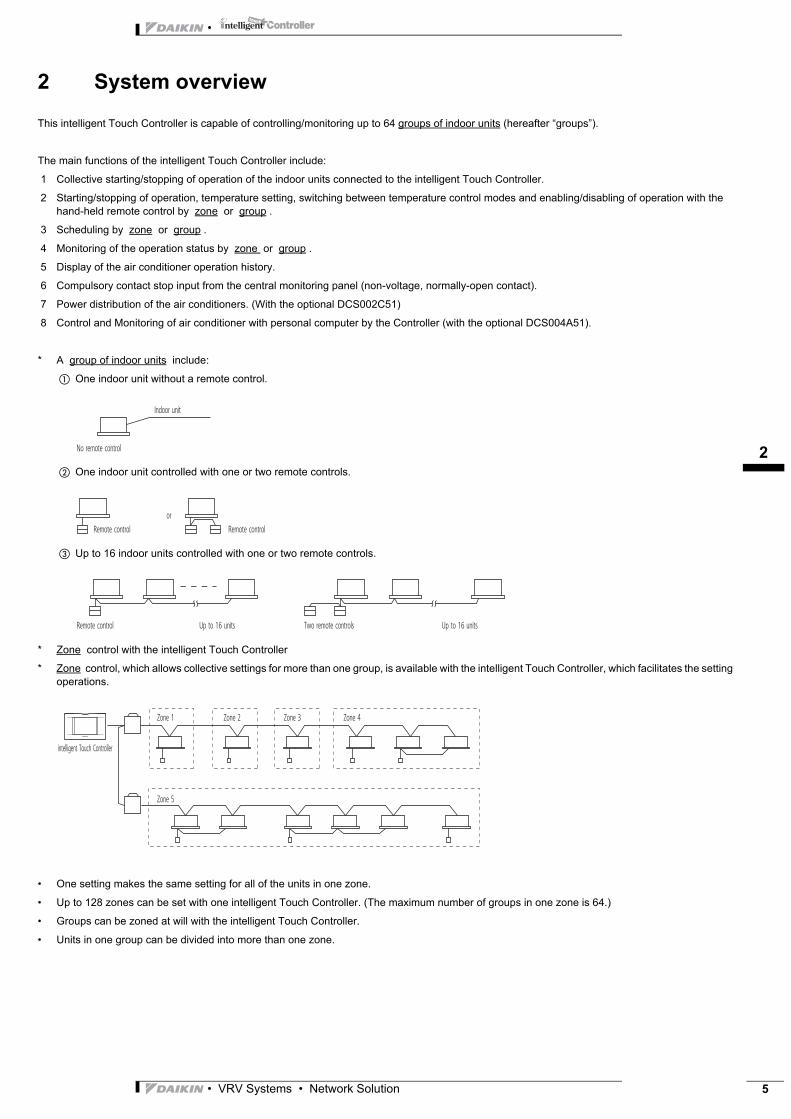
This intelligent Touch Controller is capable of controlling/monitoring up to 64 groups of indoor units (hereafter “groups”).
The main functions of the intelligent Touch Controller include:
1 Collective starting/stopping of operation of the indoor units connected to the intelligent Touch Controller.
2 Starting/stopping of operation, temperature setting, switching between temperature control modes and enabling/disabling of operation with the hand-held remote control by zone or group .
3 Scheduling by zone or group .
4 Monitoring of the operation status by zone or group .
5 Display of the air conditioner operation history.
6 Compulsory contact stop input from the central monitoring panel (non-voltage, normally-open contact).
7 Power distribution of the air conditioners. (With the optional DCS002C51)
8 Control and Monitoring of air conditioner with personal computer by the Controller (with the optional DCS004A51).
* A group of indoor units include:
� One indoor unit without a remote control.
� One indoor unit controlled with one or two remote controls.
� Up to 16 indoor units controlled with one or two remote controls.
* Zone control with the intelligent Touch Controller
* Zone control, which allows collective settings for more than one group, is available with the intelligent Touch Controller, which facilitates the setting operations.
• One setting makes the same setting for all of the units in one zone.
• Up to 128 zones can be set with one intelligent Touch Controller. (The maximum number of groups in one zone is 64.)
• Groups can be zoned at will with the intelligent Touch Controller.
• Units in one group can be divided into more than one zone.
No remote control
Indoor unit
Remote control Remote control
or
Up to 16 units Up to 16 unitsTwo remote controlsRemote control
intelligent Touch Controller
Zone 1
Zone 5
Zone 2 Zone 3 Zone 4
• VRV Systems • Network Solution 5
•
13
6
3 Part Names
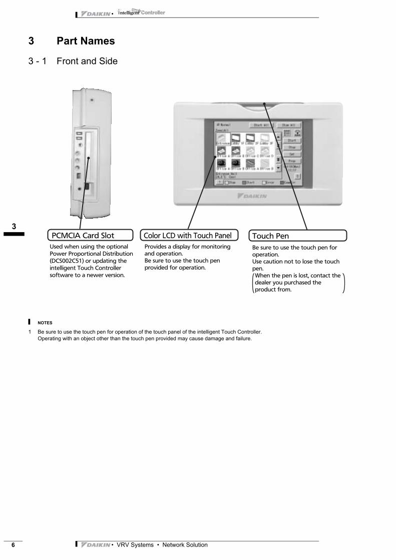
3 - 1 Front and Side
NOTES
1 Be sure to use the touch pen for operation of the touch panel of the intelligent Touch Controller.Operating with an object other than the touch pen provided may cause damage and failure.
Color LCD with Touch PanelProvides a display for monitoring and operation.Be sure to use the touch pen provided for operation.
PCMCIA Card SlotUsed when using the optional Power Proportional Distribution (DCS002C51) or updating the intelligent Touch Controller software to a newer version.
Touch PenBe sure to use the touch pen for operation.Use caution not to lose the touch pen.When the pen is lost, contact the dealer you purchased the product from.
• VRV Systems • Network Solution
13
•
3 Part Names
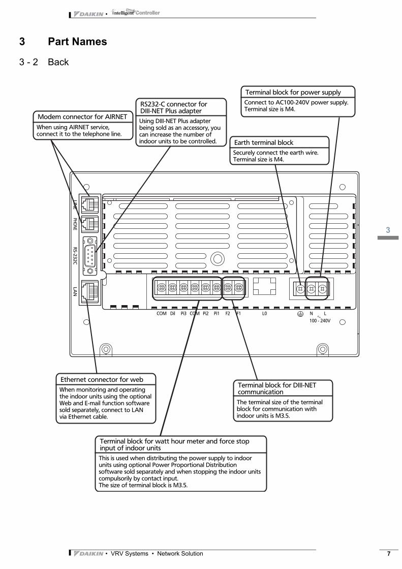
3 - 2 Back
Using DIII-NET Plus adapter being sold as an accessory, you can increase the number of indoor units to be controlled.
RS232-C connector for DIII-NET Plus adapter
When using AIRNET service, connect it to the telephone line.
Modem connector for AIRNET
This is used when distributing the power supply to indoor units using optional Power Proportional Distribution software sold separately and when stopping the indoor units compulsorily by contact input.The size of terminal block is M3.5.
Terminal block for watt hour meter and force stop input of indoor units
When monitoring and operating the indoor units using the optional Web and E-mail function software sold separately, connect to LAN via Ethernet cable.
Ethernet connector for web
Securely connect the earth wire.Terminal size is M4.
Earth terminal block
Connect to AC100-240V power supply.Terminal size is M4.
Terminal block for power supply
The terminal size of the terminal block for communication with indoor units is M3.5.
Terminal block for DIII-NET communication
LINE
COM L0Dil Pi3 COM Pi2 Pi1 F2 F1 N L
PHONE
RS-232C
LAN
100 - 240V
• VRV Systems • Network Solution 7

•
14
8
4 Detailed and easy monitoring and operation
Detailed and easy monitoring and operation of systems with up to 2x 64 groups of indoor units (with maximum 128 indoor units).
Just a touch on the screen brings up icons that make it easy to grasp any information regarding system control. The Intelligent Touch Controller enables an operator to carry out a variety of quick and easy operations, establish numerous settings and bring up screens to confirm the details.
Complete display of the status of all
air conditioners
Displays zone name
Individual names and
icons per unit
Displays system condition
(forced shutdown, etc.)
Displays detailed list of contents
ON/OFF of all air contioners Selection of zone or group display
Selection of icon, detailed icon or
list display
ON/OFF settings for selected groups
and/or zones
Displays current day and time
Displays detailed information/data
Password protection enabled/disabled
}
}
• VRV Systems • Network Solution
15
• VRV Systems • Network Solution 9
•
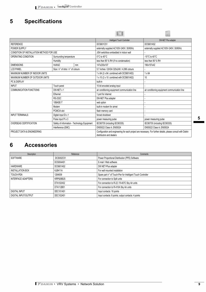
5 Specifications
6 Accessories
Intelligent Touch Controller DIII-NET Plus adapterREFERENCE DCS601C51 DCS601A52POWER SUPPLY externally supplied AC100V-240V, 50/60Hz externally supplied AC100V-240V, 50/60HzCONDITION OF INSTALLATION METHOD FOR USE JIS4 switchbox embedded in indoor wall -OPERATING CONDITION Surrounding temperature 0°C to 40°C -10°C to 40°C
Humidity less than 85 % RH (if no condensation) less than 90 % RHDIMENSIONS HxWxD mm 147x230x107 190x157x42LCD PANEL Size / n° of dots / n° of colours 5.7 inches / QVGA 320x240 / 4,096 colours -MAXIMUM NUMBER OF INDOOR UNITS 1 x 64 (2 x 64: combined with DCS601A52) 1 x 64MAXIMUM NUMBER OF OUTDOOR UNITS 1 x 10 (2 x 10: combined with DCS601A52) 10PC & DISPLAY built-in -INPUT Touch panel 10 bit encoded analog input -COMMUNICATION FUNCTIONS DIII-NET x 1 air conditioning equipment communication line air conditioning equipment communication line
Ethernet 1 port for internet -RS-232C DIII-NET Plus adapter -10BASE-T web option -Modem built-in modem for airnet -PCMCIA slot flash memory card -
INPUT TERMINALS Digital input Di x 1 forced shutdown -Pulse input Pi x 3 power measuring pulse power measuring pulse
OVERSEAS CERTIFICATION Safety of information - Technology Equipment IEC60730 (including IEC60335) IEC60730 (including IEC60335)Interference (EMC) EN55022 Class A, EN55024 EN55022 Class A, EN55024
PROJECT DATA & ENGINEERING Configuration and engineering for each project are necessary. For further details, please consult with Daikin distributors and dealers
Description Reference CommentsSOFTWARE DCS002C51 Power Proportional Distribution (PPD) Software
DCS004A51 E-mail / Web softwareHARDWARE DCS601A52 DIII NET-Plus adapterINSTALLATION BOX KJB411A For wall mounted installationTOUCH-PEN 1264009 Spare part n° of Touch-Pen for Intelligent Touch ControllerINTERFACE ADAPTERS KRP928B2S For connection to Split units
DTA102A52 For connection to R-22 / R-407C Sky Air unitsDTA112B51 For connection to R-410A Sky Air units
DIGITAL INPUT DEC101A51 Input contacts: 16 pointsDIGITAL INPUT/OUTPUT DEC102A51 Input contacts: 8 points; output contacts: 4 points
•
15
10
6 Accessories
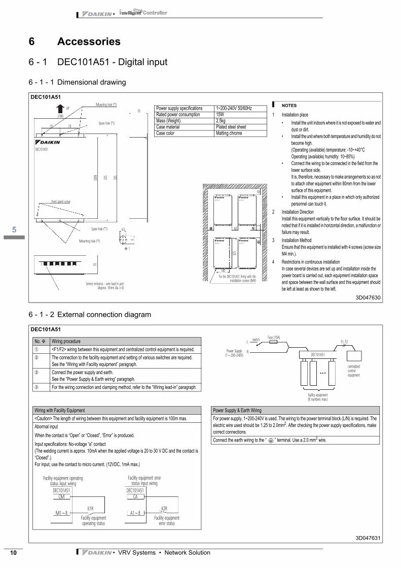
6 - 1 DEC101A51 - Digital input
6 - 1 - 1 Dimensional drawing
6 - 1 - 2 External connection diagram
DEC101A51
3D047630
DEC101A51
3D047631
Mounting hole (*1)
(198)
(309)
325
335
70 70
70
� 1
6
4.5 40 40 40
8040
325
UP
Spare hole (*1)
Mounting hole (*1)
Service entrance - wire lead-in port(Approx. 10mm dia. x 6)
Fix the DEC101A51 firmly with the installation screws (M4)
Spare hole (*1)
Front panel screw
DEC101A51
DEC101A51 DEC101A51
DEC101A51 DEC101A51
70
140
NOTES
1 Installation place• Install the unit indoors where it is not exposed to water and
dust or dirt.• Install the unit where both temperature and humidity do not
become high. (Operating (available) temperature: -10~+40°COperating (available) humidity: 10~85%)
• Connect the wiring to be connected in the field from the lower surface side.It is, therefore, necessary to make arrangements so as not to attach other equipment within 80mm from the lower surface of this equipment.
• Install this equipment in a place in which only authorized personnel can touch it.
2 Installation DirectionInstall this equipment vertically to the floor surface. It should be noted that if it is installed in horizontal direction, a malfunction or failure may result.
3 Installation MethodEnsure that this equipment is installed with 4 screws (screw size M4 min.).
4 Restrictions in continuous installationIn case several devices are set up and installation inside the power board is carried out, each equipment installation space and space between the wall surface and this equipment should be left at least as shown to the left.
Power supply specifications 1~200-240V 50/60HzRated power consumption 15WMass (Weight) 2.5kgCase material Plated steel sheetCase color Matting chrome
No. ❈ Wiring procedure➀ <F1/F2> wiring between this equipment and centralized control equipment is required.➁ The connection to the facility equipment and setting of various switches are required.
See the “Wiring with Facility equipment” paragraph.➂ Connect the power supply and earth.
See the “Power Supply & Earth wiring” paragraph.➂ For the wiring connection and clamping method, refer to the “Wiring lead-in” paragraph.
Power Supply(1~200-240V)
switchL
N
Fuse (10A)
DEC101A51
facility equipment (8 numbers max.)
centralized control equipment
F1, F2
Wiring with Facility Equipment<Caution> The length of wiring between this equipment and facility equipment is 100m max.Abormal inputWhen the contact is “Open” or “Closed”, “Error” is produced.Input specifications: No-voltage “a” contact(The welding current is approx. 10mA when the applied voltage is 20 to 30 V DC and the contact is “Closed”.)For input, use the contact to micro current. (12VDC, 1mA max.)
Facility equipment operating status input wiring
Facility equipment error status input wiring
Facility equipment error status
DEC101A51CM
K1RM1~8
DEC101A51CA
K2RA1~8
Facility equipment operating status
Power Supply & Earth WiringFor power supply, 1~200-240V is used. The wiring to the power terminal block (L/N) is required. The electric wire used should be 1.25 to 2.0mm2. After checking the power supply specifications, make correct connections.Connect the earth wiring to the “ ” terminal. Use a 2.0 mm2 wire.
• VRV Systems • Network Solution
15
•
6 Accessories
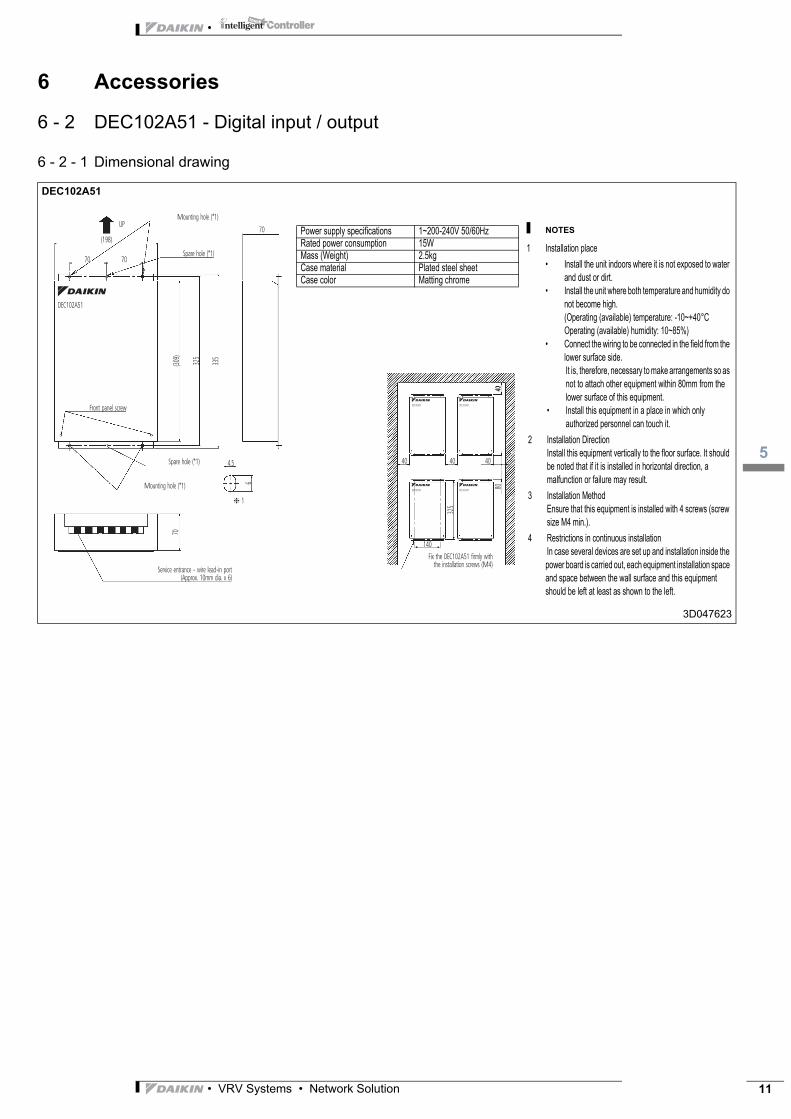
6 - 2 DEC102A51 - Digital input / output
6 - 2 - 1 Dimensional drawing
DEC102A51
3D047623
Mounting hole (*1)
(198)
(309)
325
335
70 70
70
70
� 1
6
4.5 40 40
140
40
8040
325
UP
Spare hole (*1)
Mounting hole (*1)
Service entrance - wire lead-in port(Approx. 10mm dia. x 6)
Fix the DEC102A51 firmly with the installation screws (M4)
Spare hole (*1)
Front panel screw
DEC102A51
DEC102A51 DEC102A51
DEC102A51 DEC102A51
NOTES
1 Installation place• Install the unit indoors where it is not exposed to water
and dust or dirt.• Install the unit where both temperature and humidity do
not become high. (Operating (available) temperature: -10~+40°COperating (available) humidity: 10~85%)
• Connect the wiring to be connected in the field from the lower surface side.It is, therefore, necessary to make arrangements so as not to attach other equipment within 80mm from the lower surface of this equipment.
• Install this equipment in a place in which only authorized personnel can touch it.
2 Installation DirectionInstall this equipment vertically to the floor surface. It should be noted that if it is installed in horizontal direction, a malfunction or failure may result.
3 Installation MethodEnsure that this equipment is installed with 4 screws (screw size M4 min.).
4 Restrictions in continuous installationIn case several devices are set up and installation inside the power board is carried out, each equipment installation space and space between the wall surface and this equipment should be left at least as shown to the left.
Power supply specifications 1~200-240V 50/60HzRated power consumption 15WMass (Weight) 2.5kgCase material Plated steel sheetCase color Matting chrome
• VRV Systems • Network Solution 11
•
15
12
6 Accessories
6 - 2 DEC102A51 - Digital input / output
6 - 2 - 2 External connection diagram
DEC102A51
3D047624
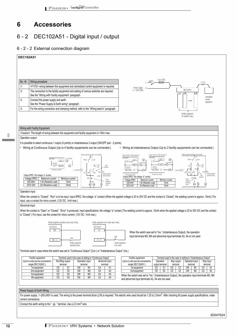
No. ❈ Wiring procedure➀ <F1/F2> wiring between this equipment and centralized control equipment is required.➁ The connection to the facility equipment and setting of various switches are required.
See the “Wiring with Facility equipment” paragraph.➂ Connect the power supply and earth.
See the “Power Supply & Earth wiring” paragraph.➂ For the wiring connection and clamping method, refer to the “Wiring lead-in” paragraph.
Power Supply(1~200-240V)
switchL
N
Fuse (10A)
DEC102A51
facility equipment (4 numbers max.)
centralized control equipment
F1, F2
Wiring with Facility Equipment<Caution> The length of wiring between this equipment and facility equipment is 100m max.Operation outputIt is possible to select continuous 1 output (4 points) or instantaneous 2 output (ON/OFF pair - 2 points).• Wiring at Continuous Output (Up to 4 facility equipments can be connected.) • Wiring at instantaneous Output (Up to 2 facility equipments can be connected.)
Operation inputWhen the contact is “Closed”, “Run” is to be input. Input SPEC: No-voltage “a” contact (When the applied voltage is 20 to 30V DC and the contact is “Closed”, the welding current is approx. 10mA.) For input, use a contact for micro current. (12V DC, 1mA max.)Abnormal inputWhen the contact is “Open” or “Closed”, “Error” is produced. Input specifications: No-voltage “a” contact (The welding current is approx. 10mA when the applied voltage is 20 to 30V DC and the contact is “Closed”.) For input, use the contact for micro current. (12V DC, 1mA max.)
Terminal used in case where the switch was set to “Continuous Output” (Con.) or “Instantaneous Output” (Ins.)
Power Supply & Earth WiringFor power supply, 1~200-240V is used. The wiring to the power terminal block (L/N) is required. The electric wire used should be 1.25 to 2.0mm2. After checking tht power supply specifications, make correct connections.Connect the earth wiring to the “ ” terminal. Use a 2.0 mm2 wire.
(Terminal size: M3.5)
Operation command
Facility equipment operation circuit example
Remote Local
Facility equipment protecting device
Facility equipment protecting device
Local operation
Local stop
DEC102A51CD
K1R
K1R K5R
K5R K3R K4R
Q1M
Q1M
Q1M
S3S
S2S
S1S
D1~4
1~200-240V
1~200-240V
Output SPEC: No-voltage “a” contactVoltage SPEC Maximum current Minimum current
200-240V 1.5A (Resistive Load) 10mADC5~24V 2A (Resistive Load) 10mA
(Terminal size: M3.5)
Operation command
Stop command
Facility equipment operation circuit example
Remote Local
Facility equipment protecting device
Facility equipment protecting device
Local operation
Local stop
DEC102A51
Output wiring for facility equipment 2
K1R
K2R
K1R K5RK5R
K2R
K5R K3R K4R
Q1M
Q1M
S3S
S2S
S1S
D4
D3
CD1~200-240V
(Terminal size: M3.5)
Operation command
Stop command
DEC102A51
Output wiring for facility equipment 1
K1R
K2RD2
D1
CD1~200-240V
1~200-240V
Output SPEC: No-voltage “a” contactVoltage SPEC Maximum current Minimum current
200-240V 1.5A (Resistive Load) 10mADC5~24V 2A (Resistive Load) 10mA
CM
K3RM1~4
CA
K4RA1~4
DEC102A51 DEC102A51
Facility equipment operating status input wiring
Facility equipment operating status
Facility equipment error status
Facility equipment error status input wiring
When the switch was set to “Ins.” (Instantaneous Output), the operation input terminals M3, M4 and abnormal input terminals A3, A4 ar not used.
Facility equipment (Up to 4 units can be connected to
single DEC102A51.)
Terminal used in the case of setting to “Continuous Output”Run/Stop output
terminalOperation input
terminalAbnormal input
terminal1st equipment CD D1 CM M1 CA A12nd equipment CD D2 CM M2 CA A23rd equipment CD D3 CM M3 CA A34th equipment CD D4 CM M4 CA A4 When the switch was set to “Ins.” (Instantaneous Output), the operation input terminals M3, M4
and abnormal input terminals A3, A4 are not used.
Facility equipment (Up to 2 units can be connected to
single DEC102A51.)
Terminal used in the case or setting to “Instantaneous Output”Operation
output terminalStop output
terminalOperation input
terminalStop input terminal
1st equipment CD D1 CD C2 CM M1 CA A12nd equipment CD D2 CD C4 CM M2 CA A2
• VRV Systems • Network Solution
17
•
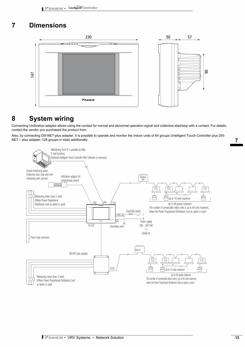
7 Dimensions
8 System wiringConnecting Unification adaptor allows using the contact for normal and abnormal operation signal and collective start/stop with a contact. For details, contact the vendor you purchased the product from.
Also, by connecting DIII-NET-plus adapter, it is possible to operate and monitor the indoor units of 64 groups (intelligent Touch Controller plus DIII-NET – plus adapter–128 groups in total) additionally.
147 90
230 50 57
Monitoring from PC is possible by Web E-mail functions. (Optional intelligent Touch Controller Web Software is necessary)
CN2 LAN F1,F2
F1,F2
F1,F2
F1,F2 F1,F2 F1,F2
F1,F2 F1,F2
DIII-NET-plus adapter
RS-232C
Outdoor unit
Up to 64 groups maximum
Up to 64 groups maximum
Up to 16 units maximum
Up to 16 units maximum
Force stop command
Measuring meter (max 3 units)
Measuring meter (max 3 units)
Power supply 100 - 240 VAC
50/60 Hz
L N
Grounding work
(Collective start, stop and error monitoring with contact)
Central monitoring panel
Unification adaptor for computerized control
(Where Power Proportional Distribution Card as option is used)
(Where Power Proportional Distribution Card as option is used)
Fuse(10A) switch(The number of connectable indoor units is up to 64 units maximum, where the Power Proportional Distribution Card as option is used.)
Outdoor unit
(The number of connectable indoor units is up to 64 units maximum, where the Power Proportional Distribution Card as option is used.)
L, N (L1, L2)
• VRV Systems • Network Solution 13

•
19
14
9 Power Proportional Distribution Card
9 - 1 Function and Outline
Power Proportional Distribution Card, in combination with an existing intelligent Touch Controller, enables to proportionally calculate and display electricity amount used by air conditioner per indoor unit.
9 - 1 - 1 Main Functions• 13 months data storage possible
• Data available per hour per indoor unit
• Power proportional distribution may be calculated for 2 x 64 indoor units at maximum.
• Power proportion distribution results data may be saved into a PCMCIA card.Data is saved CSV format generally applied to personal computers, so bills may be issued by use of a general purpose table calculation software package in easy manners.(A personal computer and a general purpose table calculation software package may be available separately.)
9 - 1 - 2 PrecautionsThis system calculates electricity consumptions by size of indoor units, run time, expansion vales open gap, suction rate and the number of pulses from the power meters installed at the Outdoor Units.This method is not calculated by direct measurement alone.
Power proportional distribution pulse.Maximum number of inputs -3.
Outdoor unit
Indoor unit
123 123 123
Power Proportional Distribution Card
Bills
Electric power meter(with pulse output)
64 units at maximum
PCMCIA card slot
DIII-NETx1
DAIKIN INDUSTRIES. LTD.
Bills may be issued by use of a general purpose table calculation software package in easy manners.
General purpose software
A personal computer and a general purpose table calculation software package may be available separately.
DCS002A51
DCS601C51
• VRV Systems • Network Solution

19
• VRV Systems • Network Solution 15
•
9 Power Proportional Distribution Card
9 - 2 File Format
When Power Proportional Distribution Report is saved, a zone information file, an electric power information file and detailed information file are created.
9 - 2 - 1 Zone information fileThis contains zone name and information of air conditioners in the zone.
(1) File name : ZONE.CSV
(2) File format:
(Example)
zone ID, Name Index
0, “ ‘all” Zone ID, zone name
1, “ 'Z-000”
2, “ 'Z-001”
3, “ 'Z-002”
One line space
zone ID, AC No. Zone ID, air conditioner number
0, 0
0, 1
1, 2
1, 3
9 - 2 - 2 Electric power information fileThis file contains Power Proportional Distribution Report and information of air conditioners.
(1) File name : YYYYMMDD - YYYYMMDD
Month and date of calculation completion
Year, month and date of calculation start
(2) File format :
(Example)
Start day, number of days, air conditioner type (0 : normal type), Undistributed Power Amount, period designation type (0 : period designation, 1 : month designation)
20050101, 31, 0, 0, 200501
One line space
Air conditioner number, indoor unit number, horse power code, electricity use amount, electric power amount at stop.0, “1:1-00”,38,2459,0,0,0,01, “1:1-01”, 38,2718,0,0,0,060, “1:4-12”, 70,489,0,0,0,0
Index

•
19
16
• VRV Systems • Network Solution
ÉEEDEN07-200/ËÍ
Daikin Europe N.V. is approved by LRQA for itsQuality Management System in accordance with theISO9001 standard. ISO9001 pertains to qualityassurance regarding design, development,manufacturing as well as to services related to theproduct.
Daikin units comply with the European regulations that guarantee the safety of the product.
EED
EN07
-200
•
07/2
007
• C
opyr
ight
• D
aiki
nTh
e pr
esen
t pu
blic
atio
n su
pers
edes
EED
E06-
2Pr
epar
ed in
Bel
gium
by
Lann
oo (
ww
w.la
nnoo
prin
t.be)
, a c
ompa
ny w
hose
con
cern
for
th
e en
viro
nmon
t is
set
in t
he E
MA
S an
d IS
O 1
4001
sys
tem
s.R
espo
nsib
le E
dito
r: D
aiki
n Eu
rope
N.V
., Za
ndvo
orde
stra
at 3
00, B
- 840
0 O
oste
nde
The present publication is drawn up by way of information only anddoes not constitute an offer binding upon Daikin Europe N.V.. DaikinEurope N.V. has compiled the content of this publication to the bestof its knowledge. No express or implied warranty is given for thecompleteness, accuracy, reliability or fitness for particular purpose ofits content and the products and services presented therein.Specifications are subject to change without prior notice. DaikinEurope N.V. explicitly rejects any liability for any direct or indirectdamage, In the broadest sense, arising from or related to the useand/or interpretation of this publication. All content is copyrightedby Daikin Europe N.V..
VRV products are not within the scope of theEurovent certification programme.
Naamloze VennootschapZandvoordestraat 300B-8400 Oostende, Belgiumwww.daikin.euBTW: BE 0412 120 336RPR Oostende
Daikin’s unique position as a manufacturer of airconditioning equipment, compressors andrefrigerants has led to its close involvement inenvironmental issues. For several years Daikinhas had the intension to become a leader in theprovision of products that have limited impacton the environment. This challenge demandsthe eco design and development of a widerange of products and an energy managementsystem, resulting in energy conservation and areduction of waste. ISO14001 assures an effective environmental
management system in order to help protect humanhealth and the environment from the potentialimpact of our activities, products and services and toassist in maintaining and improving the quality of theenvironment.


