35
TECHNICAL DATA & SERVICE MANUAL SPLIT SYSTEM AIR CONDITIONER KPAFP165R5I 38.7105.958 0.8180.451.1 09/2006 KPAFP185R5I Model No. Product Code No. KPAFP125R5I 38.7105.956 38.7105.957
| Date post: | 17-Apr-2018 |
| Category: |
Documents |
| Upload: | hoangkhanh |
| View: | 226 times |
| Download: | 3 times |

TECHNICAL DATA& SERVICE MANUAL
SPLIT SYSTEM AIR CONDITIONER
KPAFP165R5I 38.7105.958
0.8180.451.1 09/2006
KPAFP185R5I
Model No. Product Code No.KPAFP125R5I 38.7105.956
38.7105.957
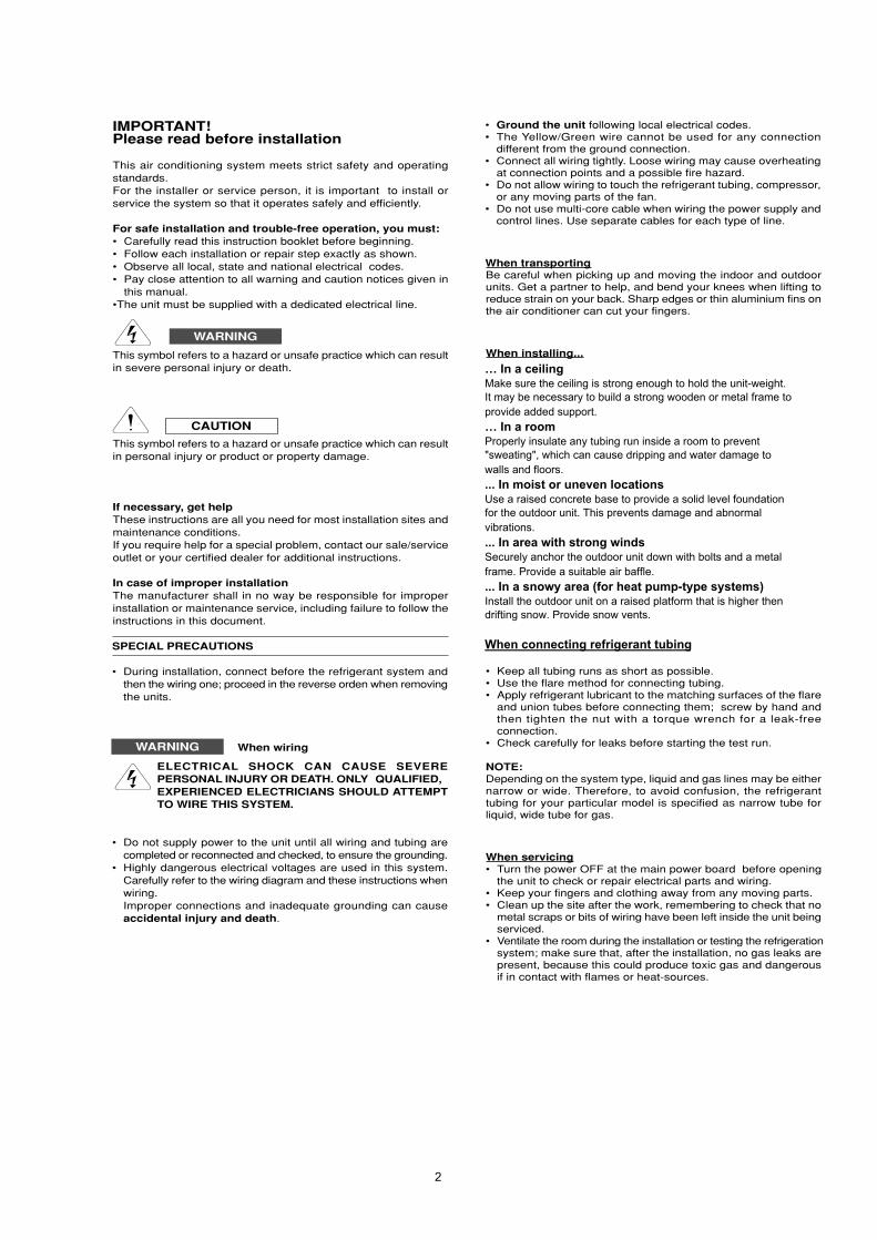
IMPORTANT!Please read before installation
This air conditioning system meets strict safety and operatingstandards.For the installer or service person, it is important to install orservice the system so that it operates safely and efficiently.
For safe installation and trouble-free operation, you must:• Carefully read this instruction booklet before beginning.• Follow each installation or repair step exactly as shown.• Observe all local, state and national electrical codes.• Pay close attention to all warning and caution notices given in
this manual.•The unit must be supplied with a dedicated electrical line.
This symbol refers to a hazard or unsafe practice which can resultin severe personal injury or death.
This symbol refers to a hazard or unsafe practice which can resultin personal injury or product or property damage.
If necessary, get helpThese instructions are all you need for most installation sites andmaintenance conditions.If you require help for a special problem, contact our sale/serviceoutlet or your certified dealer for additional instructions.
In case of improper installationThe manufacturer shall in no way be responsible for improperinstallation or maintenance service, including failure to follow theinstructions in this document.
SPECIAL PRECAUTIONS
• During installation, connect before the refrigerant system andthen the wiring one; proceed in the reverse orden when removingthe units.
When wiring
ELECTRICAL SHOCK CAN CAUSE SEVEREPERSONAL INJURY OR DEATH. ONLY QUALIFIED,EXPERIENCED ELECTRICIANS SHOULD ATTEMPTTO WIRE THIS SYSTEM.
• Do not supply power to the unit until all wiring and tubing arecompleted or reconnected and checked, to ensure the grounding.
• Highly dangerous electrical voltages are used in this system.Carefully refer to the wiring diagram and these instructions whenwiring.Improper connections and inadequate grounding can causeaccidental injury and death.
• Ground the unit following local electrical codes.• The Yellow/Green wire cannot be used for any connection
different from the ground connection.• Connect all wiring tightly. Loose wiring may cause overheating
at connection points and a possible fire hazard.• Do not allow wiring to touch the refrigerant tubing, compressor,
or any moving parts of the fan.• Do not use multi-core cable when wiring the power supply and
control lines. Use separate cables for each type of line.
When transportingBe careful when picking up and moving the indoor and outdoorunits. Get a partner to help, and bend your knees when lifting toreduce strain on your back. Sharp edges or thin aluminium fins onthe air conditioner can cut your fingers.
When installing...
• Keep all tubing runs as short as possible.• Use the flare method for connecting tubing.• Apply refrigerant lubricant to the matching surfaces of the flare
and union tubes before connecting them; screw by hand andthen tighten the nut with a torque wrench for a leak-freeconnection.
• Check carefully for leaks before starting the test run.
NOTE:Depending on the system type, liquid and gas lines may be eithernarrow or wide. Therefore, to avoid confusion, the refrigeranttubing for your particular model is specified as narrow tube forliquid, wide tube for gas.
When servicing• Turn the power OFF at the main power board before opening
the unit to check or repair electrical parts and wiring.• Keep your fingers and clothing away from any moving parts.• Clean up the site after the work, remembering to check that no
metal scraps or bits of wiring have been left inside the unit beingserviced.
• Ventilate the room during the installation or testing the refrigerationsystem; make sure that, after the installation, no gas leaks arepresent, because this could produce toxic gas and dangerousif in contact with flames or heat-sources.
WARNING
CAUTION
WARNING
… In a ceilingMake sure the ceiling is strong enough to hold the unit-weight.It may be necessary to build a strong wooden or metal frame toprovide added support.… In a roomProperly insulate any tubing run inside a room to prevent"sweating", which can cause dripping and water damage towalls and floors.... In moist or uneven locationsUse a raised concrete base to provide a solid level foundationfor the outdoor unit. This prevents damage and abnormalvibrations.... In area with strong windsSecurely anchor the outdoor unit down with bolts and a metalframe. Provide a suitable air baffle.... In a snowy area (for heat pump-type systems)Install the outdoor unit on a raised platform that is higher thendrifting snow. Provide snow vents.
When connecting refrigerant tubing
2

Page
1. SPECIFICATIONS 41-1 Unit specifications 41-2 Major Component specifications 61-3 Other Component specifications 8
2. DIMENSIONAL DATA 9
3. ELECTRICAL DATA 103-1 Electric Wiring Diagram 103-2 Control PCB switches and functions 11
4. PROCESS AND FUNCTIONS 124-1 Control function 12
5. REPLACING PCB 155-1 Replacing PCB 155-2 How to replace PCB 165-3 How to replace EEPROM with EEPROM included in PCB service pack 175-4 Table of setting 19
6. SERVICE PROCEDURE 206-1 Meaning of alarm message 206-2 Led indicator messages on outdoor control PCB 216-3 Symptoms and parts to inspect 226-4 Details of alarm messages 236-5 Table of thermistor characteristics 26
7. OUTDOOR UNIT MAINTENANCE REMOTE CONTROL 277-1 Overwiew 277-2 Functions 277-3 Normal display operations and functions 287-4 Monitoring operations:
Display of indoor unit and outdoor unit sensor temperatures 317-5 Monitoring the outdoor unit alarm history:
Display of outdoor unit alarm history 327-6 Setting modes: setting of outdoor unit EEPROM 32
Table of Contents
3
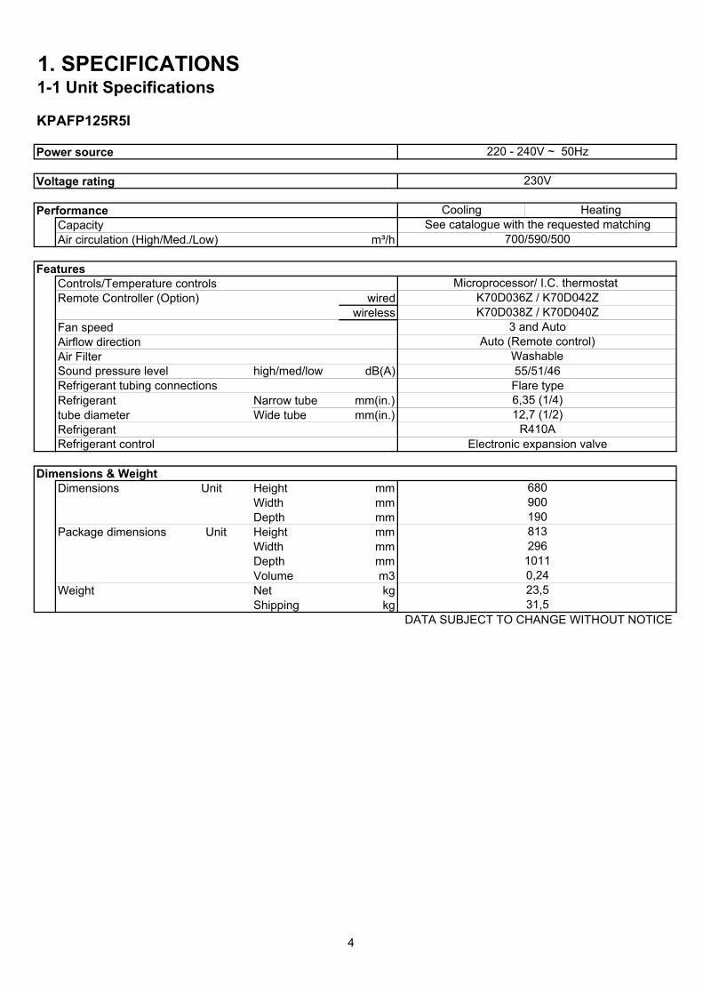
1. SPECIFICATIONS1-1 Unit Specifications
KPAFP125R5I
Power source
Voltage rating
PerformanceCapacityAir circulation (High/Med./Low) m³/h
FeaturesControls/Temperature controlsRemote Controller (Option) wired
wirelessFan speedAirflow direction Air FilterSound pressure level high/med/low dB(A)Refrigerant tubing connectionsRefrigerant Narrow tube mm(in.)tube diameter Wide tube mm(in.)RefrigerantRefrigerant control
Dimensions & WeightDimensions Unit Height mm
Width mmDepth mm
Package dimensions Unit Height mmWidth mmDepth mmVolume m3
Weight Net kgShipping kg
DATA SUBJECT TO CHANGE WITHOUT NOTICE
680
Auto (Remote control)
Electronic expansion valve
Washable55/51/46Flare type6,35 (1/4)12,7 (1/2)
R410A
220 - 240V ~ 50Hz
230V
Cooling HeatingSee catalogue with the requested matching
700/590/500
Microprocessor/ I.C. thermostat
3 and Auto
K70D036Z / K70D042ZK70D038Z / K70D040Z
296
23,531,5
900
0,24
813
1011
190
4
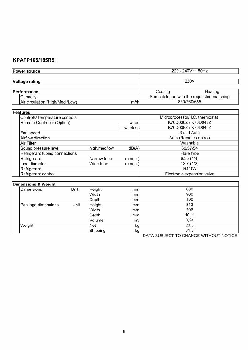
KPAFP165/185R5I
Power source
Voltage rating
PerformanceCapacityAir circulation (High/Med./Low) m³/h
FeaturesControls/Temperature controlsRemote Controller (Option) wired
wirelessFan speedAirflow direction Air FilterSound pressure level high/med/low dB(A)Refrigerant tubing connectionsRefrigerant Narrow tube mm(in.)tube diameter Wide tube mm(in.)RefrigerantRefrigerant control
Dimensions & WeightDimensions Unit Height mm
Width mmDepth mm
Package dimensions Unit Height mmWidth mmDepth mmVolume m3
Weight Net kgShipping kg
DATA SUBJECT TO CHANGE WITHOUT NOTICE
Electronic expansion valve
Flare type
31,5
81329610110,2423,5
190
220 - 240V ~ 50Hz
230V
Cooling HeatingSee catalogue with the requested matching
Microprocessor/ I.C. thermostat
830/760/665
K70D038Z / K70D040Z
900680
K70D036Z / K70D042Z
Washable
6,35 (1/4)
R410A12,7 (1/2)
3 and AutoAuto (Remote control)
60/57/54
5
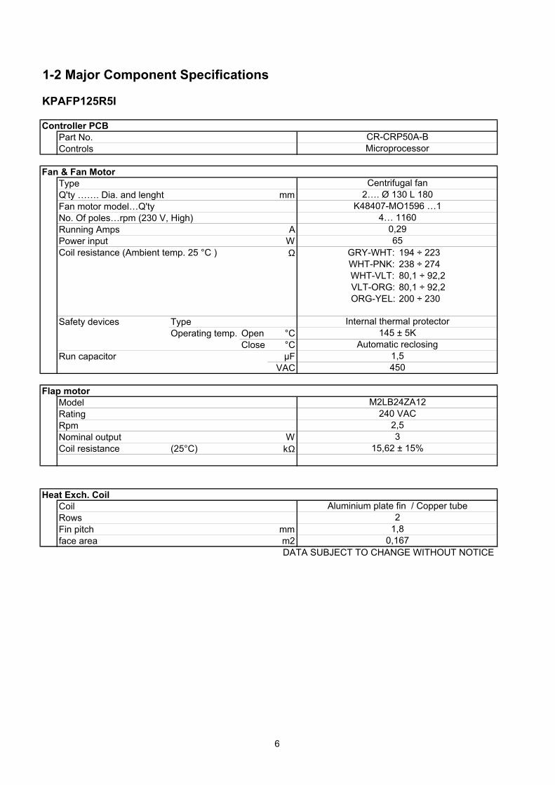
1-2 Major Component Specifications
KPAFP125R5I
Controller PCBPart No.Controls
Fan & Fan MotorTypeQ'ty ……. Dia. and lenght mmFan motor model…Q'tyNo. Of poles…rpm (230 V, High)Running Amps APower input WCoil resistance (Ambient temp. 25 °C ) Ω GRY-WHT: 194 ÷ 223
WHT-PNK: 238 ÷ 274WHT-VLT: 80,1 ÷ 92,2VLT-ORG: 80,1 ÷ 92,2ORG-YEL: 200 ÷ 230
Safety devices TypeOperating temp. Open °C
Close °CRun capacitor µF
VAC
Flap motorModelRatingRpmNominal output WCoil resistance (25°C) kΩ
Heat Exch. CoilCoilRowsFin pitch mmface area m2
DATA SUBJECT TO CHANGE WITHOUT NOTICE
4501,5
Internal thermal protector145 ± 5K
Automatic reclosing
MicroprocessorCR-CRP50A-B
2…. Ø 130 L 180
0,2965
Centrifugal fan
K48407-MO1596 …14… 1160
M2LB24ZA12
15,62 ± 15%
2,5
0,167
Aluminium plate fin / Copper tube
3
1,82
240 VAC
6
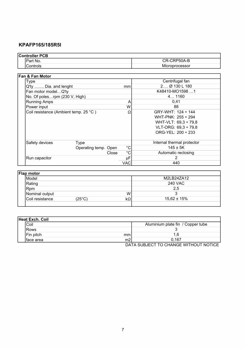
KPAFP165/185R5I
Controller PCBPart No.Controls
Fan & Fan MotorTypeQ'ty ……. Dia. and lenght mmFan motor model…Q'tyNo. Of poles…rpm (230 V, High)Running Amps APower input WCoil resistance (Ambient temp. 25 °C ) Ω GRY-WHT: 124 ÷ 144
WHT-PNK: 255 ÷ 294WHT-VLT: 69,3 ÷ 79,8VLT-ORG: 69,3 ÷ 79,8ORG-YEL: 200 ÷ 233
Safety devices TypeOperating temp. Open °C
Close °CRun capacitor µF
VAC
Flap motorModelRatingRpmNominal output WCoil resistance (25°C) kΩ
Heat Exch. CoilCoilRowsFin pitch mmface area m2
DATA SUBJECT TO CHANGE WITHOUT NOTICE0,1671,63
Aluminium plate fin / Copper tube
Automatic reclosing
2,53
M2LB24ZA12240 VAC
2440
CR-CRP50A-B
Centrifugal fan
15,62 ± 15%
Microprocessor
2…. Ø 130 L 180K48410-MO1598 …1
4… 11600,4188
Internal thermal protector145 ± 5K
7
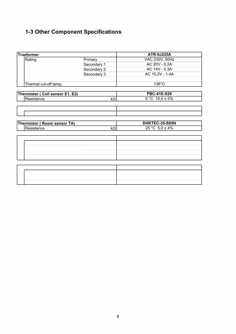
1-3 Other Component Specifications
TrasformerRating Primary
Secondary 1Secondary 2Secondary 3
Thermal cut-off temp.
Thermistor ( Coil sensor E1, E2)Resistance kΩ
Thermistor ( Room sensor TA)Resistance kΩ
ATR-IIJ225AVAC 230V, 50Hz
AC 20V - 0.2AAC 14V - 0.3A
PBC-41E-S26
AC 10,2V - 1.4A
136°C
0 °C 15,0 ± 5%
25 °C 5,0 ± 4%DHKTEC-35-S85N
8
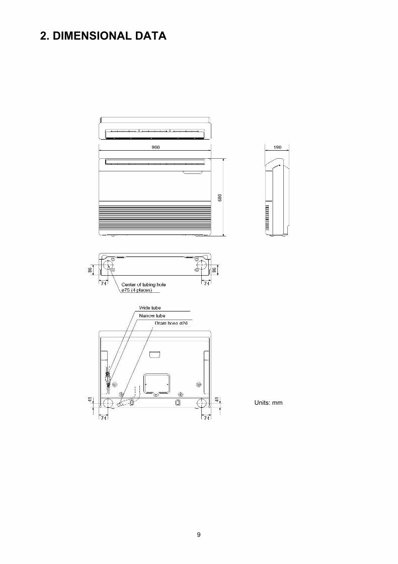
2. DIMENSIONAL DATA
Units: mm
9
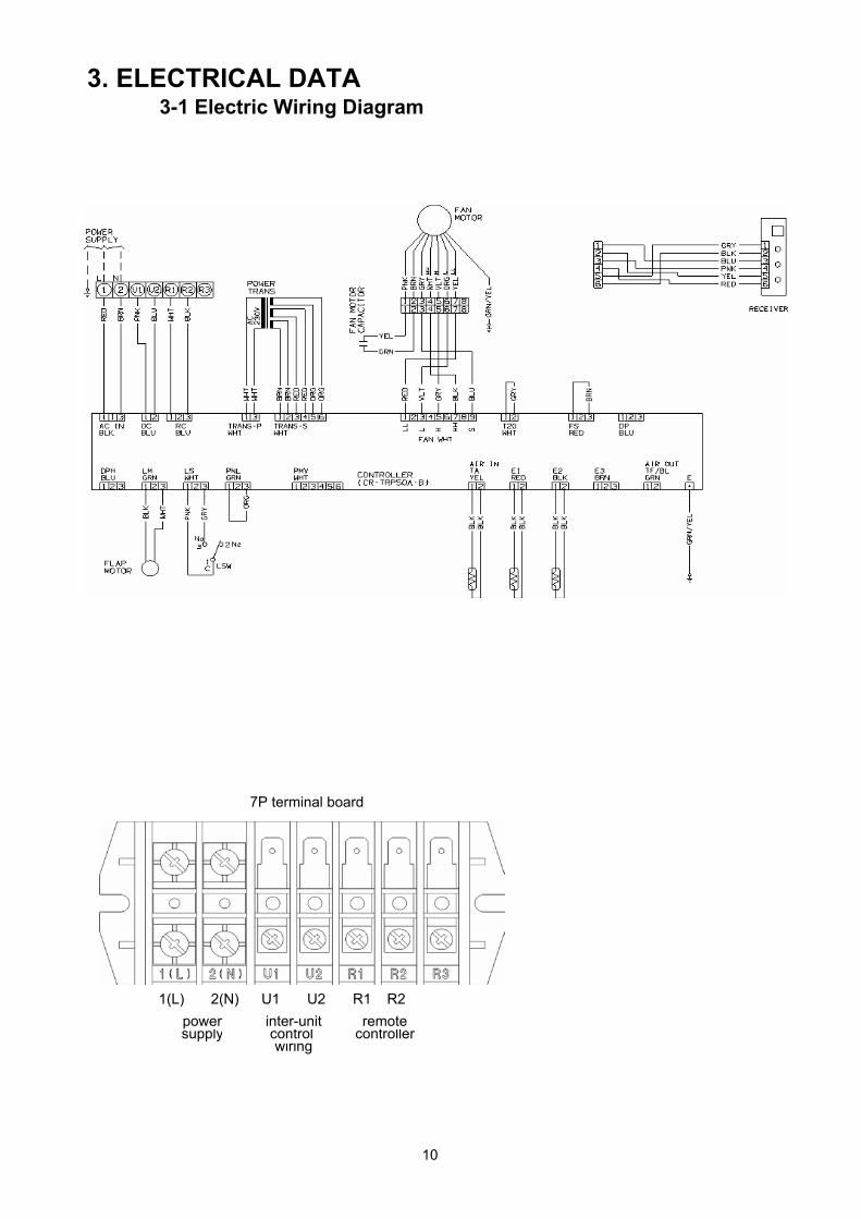
3. ELECTRICAL DATA3-1 Electric Wiring Diagram
7P terminal board
1(L) 2(N) U1 U2 R1 R2
wiring
remotecontroller
powersupply
inter-unitcontrol
10

3-2 Control PCB switches and functions
CR-TRP50A-B OC (CN040)EMG (CN044)
VARISTOR(VA041)
JP1 DISP (CN072)EXCT (CN073) FILTER (JP001)
(CN070) CHK (CN071)FAN DRIVE GRL
(CN032) (CN020) T10 (CN061)POWER LED
(D002) EEPROM(IC010)
T10: 6 plug (yellow): used for remote control. (Refer to the remote control section)(CN061) 1- start/stop input 2- COM
3- remote control prohibit/release input 4- start signal output5- COM (+DC12v) 6- alarm signal output T10
EXCT: 2P plug (red): Can be used for demand control. When imput is present, forces the unit to operate(CN073) with the termostat OFF.
DISP: 2P plug (white): Short-circuiting this plug allows the unit to be operated by the remote controller, even if it is not(CN072) connected to an outdoor unit. (In this case, alarm "E04", which indicates trouble in the serial communication
between the indoor and outdoor unit, does not occur.)
CHK: 2P plug (white): Test pin. Short-circuiting this pin allows the indoor FM (H fan speed), drain pump,(CN071) flap motor (F1 position), and electronic expansion valve full-open position to checked. However this function
turns OFF if the indoor unit protection mechanism is activated. The unit can be operated even if the remotecontroller and outdoor unit are not connected. However even if the remote controller cannot is connected,it cannot be used to operate the unit. This function can be used for short-term tests.
JP1: Jumper wire: Allows selection of the T10 terminal(JP001)
11

4. PROCESS AND FUNCTIONS4-1 control functions
12
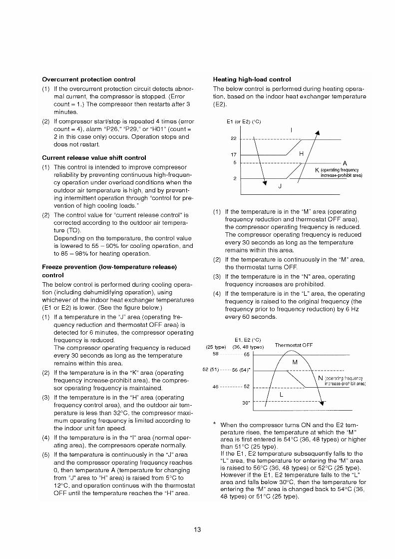
13

14

5. REPLACING PCB5-1 Replacing PCB
About EEPROM(Erasable Programmable Read-Only Memory)EEPROM is a component in which the various information necessary for functionningcan be electronically written or erased. This component holds informationsthat is essential for the running of the unit, and must be handled with care.
D002led lamp (red)
15

5-2 How to replace PCB
16

5-3 How to replace EEPROM with EEPROM included in PCB service pack
17
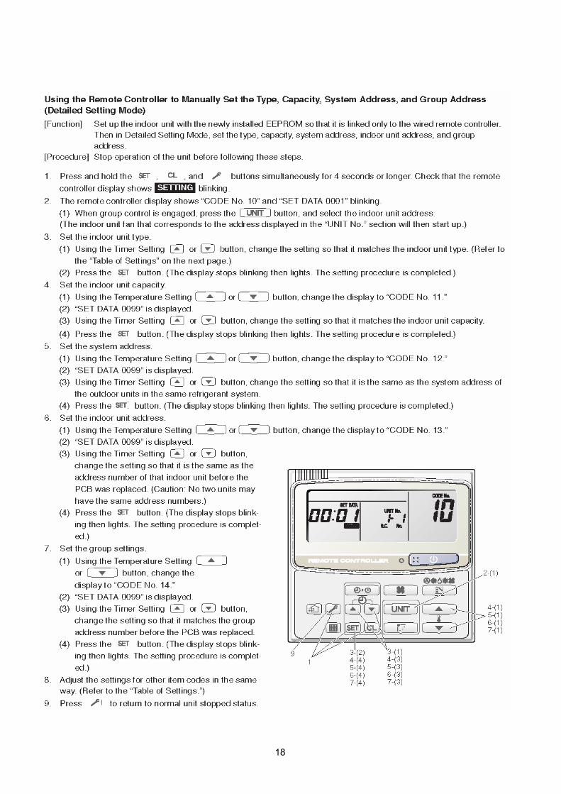
18

5-4 Table of settings
19

6. SERVICE PROCEDURE6-1 Meaning of alarm message
20

6-2 Led indicator messages on outdoor control PCB
21
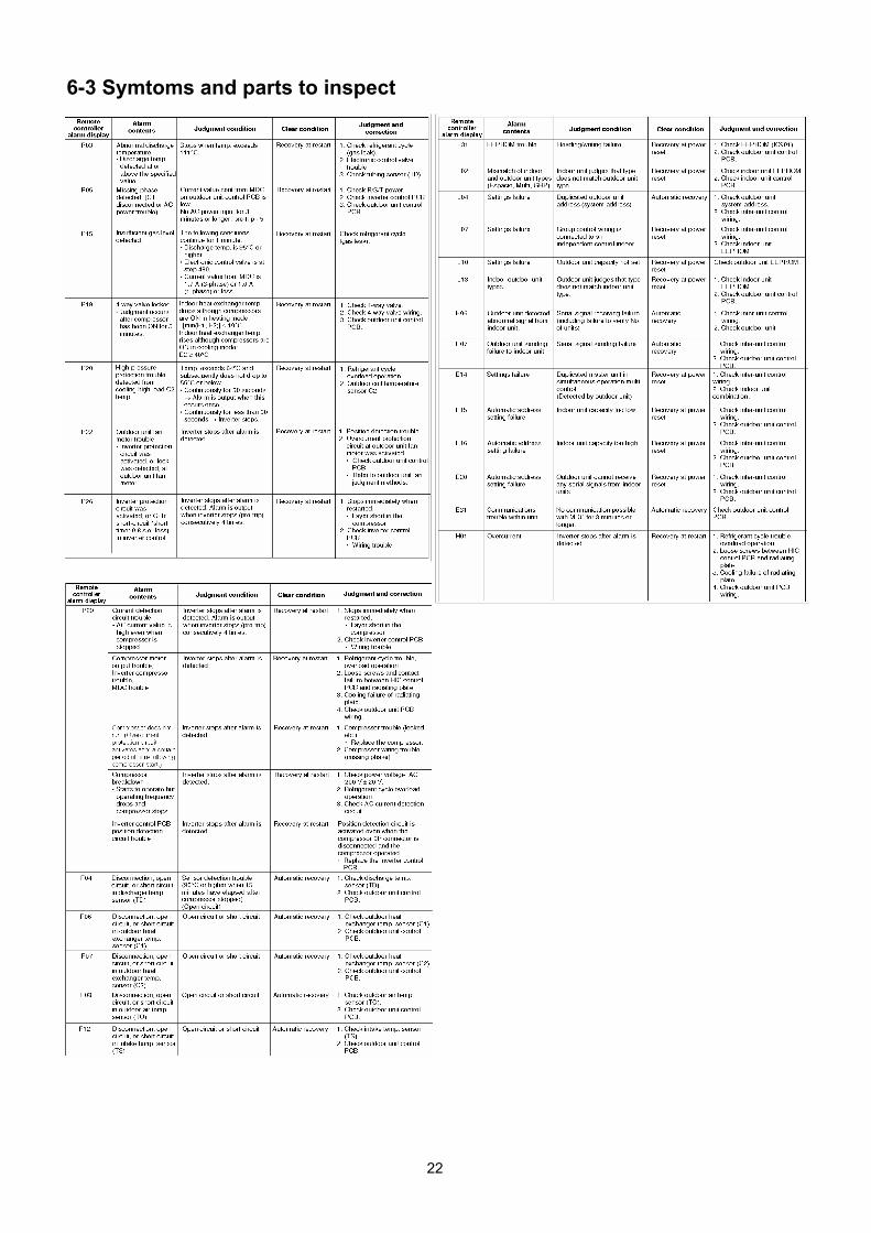
6-3 Symtoms and parts to inspect
22

6-4 Details of alarm messages
resistance
23

24

25
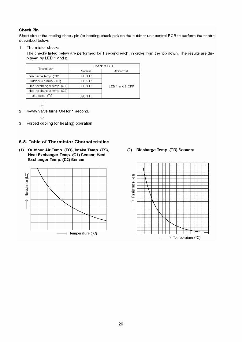
26
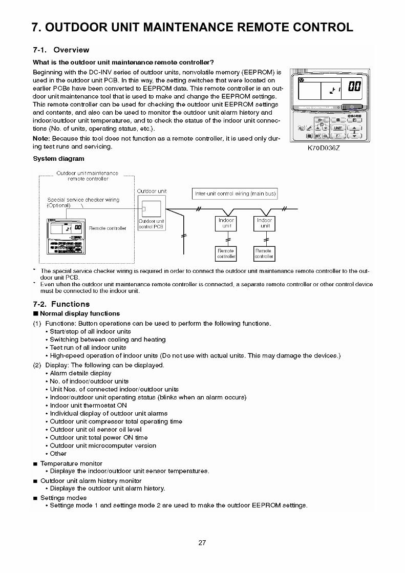
7. OUTDOOR UNIT MAINTENANCE REMOTE CONTROL
27

28

29

30
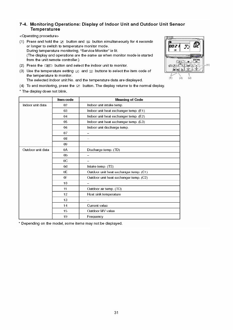
31

32

33
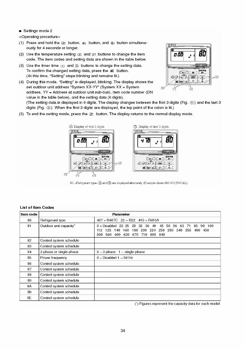
34

R.D. 28 Reyrieux BP 131 - 01601 Trévoux CEDEX FranceTél. 04.74.00.92.92 - Fax 04.74.00.42.00R.C.S. Bourg-en-Bresse B 759 200 728


