+ All Categories
Home > Documents > TECHNICAL DATA SHEET Composite Trench System 1.76m Deep …

TECHNICAL DATA SHEET Composite Trench System 1.76m Deep …

Date post: 20-Jan-2022
Category:
Upload: others
View: 2 times
Download: 0 times
Share this document with a friend
18
TECHNICAL DATA SHEET COMPOSITE TRENCH SYSTEM: 1.76M DEEP X 3.0M WIDE WWW.EZE-SHORING.CO.UK / [email protected] / 01422 203222 1 TECHNICAL DATA SHEET Composite Trench System 1.76m Deep x 3.0m Wide
Transcript

TECHNICAL DATA SHEET COMPOSITE TRENCH SYSTEM: 1.76M DEEP X 3.0M WIDE

WWW.EZE-SHORING.CO.UK / [email protected] / 01422 203222 1

TECHNICAL DATA SHEETComposite Trench System1.76m Deep x 3.0m Wide

TECHNICAL DATA SHEET COMPOSITE TRENCH SYSTEM: 1.76M DEEP X 3.0M WIDE

WWW.EZE-SHORING.CO.UK / [email protected] / 01422 203222 2

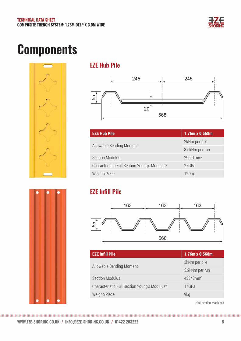
EZE Shoring Composite Trench Lining SystemThe EZE Shoring composite trench lining system is the world’s first non-metallic trench lining system. Manufactured by Exel Composites UK, this high performance composite system comprises of only five different components.

The lightweight, easy to assemble system uses composite struts (where necessary) to make it 100% non-conductive. This makes it the safest, easiest and lightest trench lining product available for the installation of underground utilities – gas , water, and electricity. (Steel struts can also be utilised in the system as an alternative option if conductivity is not a critical factor.)

EZE Shoring offers simplicity, with no pins, clips, slings, pumps or hydraulics to worry about. Each individual component weighs less than 25kg.

Easily fitting into a ‘transit van’ for rapid deployment if required, the system is very flexible in accommodating different depths and trench lengths, see pages 8—13 for further details.

EZE Shoring is patent and design protected in the UK and Internationally.

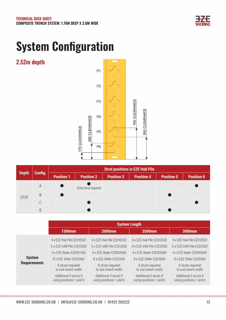
EZE Shoring can be utilised in excavations 2.52m deep and in widths up to 1.7m wide, (See pages 10 - 13 for system and configuration details) and up to 2.5m wide with metallic props if required.

TECHNICAL DATA SHEET COMPOSITE TRENCH SYSTEM: 1.76M DEEP X 3.0M WIDE

WWW.EZE-SHORING.CO.UK / [email protected] / 01422 203222 3

Set-up Configuration A

TECHNICAL DATA SHEET COMPOSITE TRENCH SYSTEM: 1.76M DEEP X 3.0M WIDE

WWW.EZE-SHORING.CO.UK / [email protected] / 01422 203222 4

Set-up Configuration B

TECHNICAL DATA SHEET COMPOSITE TRENCH SYSTEM: 1.76M DEEP X 3.0M WIDE

WWW.EZE-SHORING.CO.UK / [email protected] / 01422 203222 5

Components

EZE Hub Pile 1.76m x 0.568m

Allowable Bending Moment2kNm per pile

3.5kNm per run

Section Modulus 29991mm3

Characteristic Full Section Young’s Modulus* 27GPa

Weight/Piece 12.7kg

*Full section, machined

EZE Infill Pile 1.76m x 0.568m

Allowable Bending Moment3kNm per pile

5.2kNm per run

Section Modulus 43348mm3

Characteristic Full Section Young’s Modulus* 17GPa

Weight/Piece 9kg

EZE Hub Pile

EZE Infill Pile

245

56820

55

245

55

163 163 163

568

TECHNICAL DATA SHEET COMPOSITE TRENCH SYSTEM: 1.76M DEEP X 3.0M WIDE

WWW.EZE-SHORING.CO.UK / [email protected] / 01422 203222 6

ComponentsComponents

EZE Waler 3m

Allowable Bending Moment 6kNm

Section Modulus 28412mm3

Characteristic Full Section Young’s Modulus* 34GPa

Weight/Piece 25kg

EZE Slider 0.56m

Allowable Bending Moment N/A

Section Modulus 61533mm3

Characteristic Full Section Young’s Modulus* 23GPa

Weight/Piece 2.6kg

EZE Waler

EZE Slider

210

160

5068

273

TECHNICAL DATA SHEET COMPOSITE TRENCH SYSTEM: 1.76M DEEP X 3.0M WIDE

WWW.EZE-SHORING.CO.UK / [email protected] / 01422 203222 7

Components

EZE Strut

EZE Strut Type 1 511mm / 711mm (Open/Closed)

EZE Strut Type 2 706mm / 1107mm (Open/Closed)

EZE Strut Type 3 1041mm / 1741mm (Open/Closed)

Composite Strut 30kN SWL (Open/Closed)

EZE Strut

Note: For standard use the system takes a metallic prop with a 150mm base plate on each end.

Fully Open

Fully Closed

Interchangeable end plate with threaded spigot

(metallic or non-metallic)

Threaded sleeve with thrust ring to

adjust length

Threaded insert inside tube to accept end

plate spigot

Section A-A

Section B-B

Outer Tube Shear Pin Inner Tube

A

A

B

B

TECHNICAL DATA SHEET COMPOSITE TRENCH SYSTEM: 1.76M DEEP X 3.0M WIDE

WWW.EZE-SHORING.CO.UK / [email protected] / 01422 203222 8

EZE Shoring System Set-up

EZE Shoring System 1.76m deep x 3m wide

System SWL 18kNm

Maximum excavation depth 1760mm

Excavation width600 mm – 1750mm (composite strut) Up to 2500mm with metallic prop

Maximum clearance between sliders struts 1700mm

Maximum clearance to lower strut 765mm

3000

1760

Composite Strut 600 - 1750

(up to 2500 with acrow strut)

765

550385

170

Cle

aran

ce

TECHNICAL DATA SHEET COMPOSITE TRENCH SYSTEM: 1.76M DEEP X 3.0M WIDE

WWW.EZE-SHORING.CO.UK / [email protected] / 01422 203222 9

EZE Shoring System Set-up

EZE Shoring System 1.38m – 2.52m deep x 1.5m – 3m wide

System SWL 18kNm

Maximum excavation depth 2520mm

Excavation width600 mm – 1750mm (composite strut) Up to 2500mm with metallic prop

Maximum clearance between sliders struts 1200mm – 1700mm

Maximum clearance to lower strut 765mm

1380 – 2520

1500

– 30

00

TECHNICAL DATA SHEET COMPOSITE TRENCH SYSTEM: 1.76M DEEP X 3.0M WIDE

WWW.EZE-SHORING.CO.UK / [email protected] / 01422 203222 10

System Configuration1.38m depth

Depth Config.Strut positions in EZE Hub Pile

Position 1 Position 2 Position 3 Position 4 Position 5 Position 6

1380A

B

System Length

1500mm 2000mm 2500mm 3000mm

System Requirements

4 x EZE Hub Pile EZEH1380

2 x EZE Infill Pile EZEI1380

4 x EZE Waler EZEW1500

8 x EZE Slider EZES560

8 struts required to suit trench width

6 x EZE Hub Pile EZEH1380

2 x EZE Infill Pile EZEI1380

4 x EZE Waler EZEW2000

8 x EZE Slider EZES560

8 struts required to suit trench width

6 x EZE Hub Pile EZEH1380

4 x EZE Infill Pile EZEI1380

4 x EZE Waler EZEW2500

8 x EZE Slider EZES560

8 struts required to suit trench width

6 x EZE Hub Pile EZEH1380

6 x EZE Infill Pile EZEI1380

4 x EZE Waler EZEW3000

8 x EZE Slider EZES560

8 struts required to suit trench width

TECHNICAL DATA SHEET COMPOSITE TRENCH SYSTEM: 1.76M DEEP X 3.0M WIDE

WWW.EZE-SHORING.CO.UK / [email protected] / 01422 203222 11

System Configuration1.76m depth

Depth Config.Strut positions in EZE Hub Pile

Position 1 Position 2 Position 3 Position 4 Position 5 Position 6

1760A

B

System Length

1500mm 2000mm 2500mm 3000mm

System Requirements

4 x EZE Hub Pile EZEH1760

2 x EZE Infill Pile EZEI1760

4 x EZE Waler EZEW1500

8 x EZE Slider EZES560

8 struts required to suit trench width

6 x EZE Hub Pile EZEH1760

2 x EZE Infill Pile EZEI1760

4 x EZE Waler EZEW2000

8 x EZE Slider EZES560

8 struts required to suit trench width

6 x EZE Hub Pile EZEH1760

4 x EZE Infill Pile EZEI1760

4 x EZE Waler EZEW2500

8 x EZE Slider EZES560

8 struts required to suit trench width

6 x EZE Hub Pile EZEH1760

6 x EZE Infill Pile EZEI1760

4 x EZE Waler EZEW3000

8 x EZE Slider EZES560

8 struts required to suit trench width

TECHNICAL DATA SHEET COMPOSITE TRENCH SYSTEM: 1.76M DEEP X 3.0M WIDE

WWW.EZE-SHORING.CO.UK / [email protected] / 01422 203222 12

System Configuration2.14m depth

Depth Config.Strut positions in EZE Hub Pile

Position 1 Position 2 Position 3 Position 4 Position 5 Position 6

2140

A

B

C

D

System Length

1500mm 2000mm 2500mm 3000mm

System Requirements

4 x EZE Hub Pile EZEH2140

2 x EZE Infill Pile EZEI2140

4 x EZE Waler EZEW1500

8 x EZE Slider EZES560

8 struts required to suit trench width

6 x EZE Hub Pile EZEH2140

2 x EZE Infill Pile EZEI2140

4 x EZE Waler EZEW2000

8 x EZE Slider EZES560

8 struts required to suit trench width

6 x EZE Hub Pile EZEH2140

4 x EZE Infill Pile EZEI2140

4 x EZE Waler EZEW2500

8 x EZE Slider EZES560

8 struts required to suit trench width

6 x EZE Hub Pile EZEH2140

6 x EZE Infill Pile EZEI2140

4 x EZE Waler EZEW3000

8 x EZE Slider EZES560

8 struts required to suit trench width

TECHNICAL DATA SHEET COMPOSITE TRENCH SYSTEM: 1.76M DEEP X 3.0M WIDE

WWW.EZE-SHORING.CO.UK / [email protected] / 01422 203222 13

System Configuration2.52m depth

Depth Config.Strut positions in EZE Hub Pile

Position 1 Position 2 Position 3 Position 4 Position 5 Position 6

2520

A Extra strut required

B

C

B

System Length1500mm 2000mm 2500mm 3000mm

System Requirements

4 x EZE Hub Pile EZEH2520

2 x EZE Infill Pile EZEI2520

4 x EZE Waler EZEW1500

8 x EZE Slider EZES560

8 struts required to suit trench width

Additional 3 struts if using positions 1 and 6

6 x EZE Hub Pile EZEH2520

2 x EZE Infill Pile EZEI2520

4 x EZE Waler EZEW2000

8 x EZE Slider EZES560

8 struts required to suit trench width

Additional 3 struts if using positions 1 and 6

6 x EZE Hub Pile EZEH2520

4 x EZE Infill Pile EZEI2520

4 x EZE Waler EZEW2500

8 x EZE Slider EZES560

8 struts required to suit trench width

Additional 3 struts if using positions 1 and 6

6 x EZE Hub Pile EZEH2520

6 x EZE Infill Pile EZEI2520

4 x EZE Waler EZEW3000

8 x EZE Slider EZES560

8 struts required to suit trench width

Additional 3 struts if using positions 1 and 6

TECHNICAL DATA SHEET COMPOSITE TRENCH SYSTEM: 1.76M DEEP X 3.0M WIDE

WWW.EZE-SHORING.CO.UK / [email protected] / 01422 203222 14

Dimensions

TECHNICAL DATA SHEET COMPOSITE TRENCH SYSTEM: 1.76M DEEP X 3.0M WIDE

WWW.EZE-SHORING.CO.UK / [email protected] / 01422 203222 15

Site Assembly

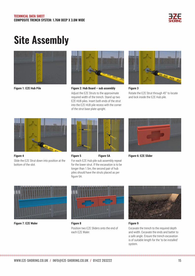
Figure 1: EZE Hub Pile Figure 2: Hub Board – sub assemblyAdjust the EZE Struts to the approximate required width of the trench. Stand up two EZE HUB piles. Insert both ends of the strut into the EZE HUB pile recess with the corner of the strut base plate upright.

Figure 3Rotate the EZE Strut through 45° to locate and lock inside the EZE Hub pile.

Figure 4Slide the EZE Strut down into position at the bottom of the slot.

Figure 5 Figure 5AFor each EZE Hub pile sub assembly repeat for the lower strut. If the excavation is to be longer than 1.5m, the second pair of hub piles should have the struts placed as per figure 5A.

Figure 6: EZE Slider

Figure 7: EZE Waler Figure 8Position two EZE Sliders onto the end of each EZE Waler.

Figure 9Excavate the trench to the required depth and width. Excavate the ends and batter to a safe angle. Ensure the trench excavation is of suitable length for the ‘to be installed’ system.

TECHNICAL DATA SHEET COMPOSITE TRENCH SYSTEM: 1.76M DEEP X 3.0M WIDE

WWW.EZE-SHORING.CO.UK / [email protected] / 01422 203222 16

Site Assembly

Figure 10Lift the EZE Hub pile sub assembly and position at the top of the battered end of the excavation – 2 persons required. With one person either side of the excavation, lower the sub assembly into position.

Figure 11Operators should be a safe distance from excavation edge, ensure operatives are always in line with the assembly.

Figure 12Lift the second EZE Hub pile assembly and place at a distance 500mm apart from the first. Position 2 is approx. 1100mm from the bottom of the battered end.

Figure 16Lower the EZE Waler assembly down to the operative in the excavation, these rest on the top of the EZE Hub assembly. Insert struts into the EZE Sliders and move the slider over the second pair of EZE Hub piles.

Figure 17Insert the EZE Infill pile behind the waler on both sides. Remove EZE Struts from 2nd pair of EZE Hub piles to give maximum open working area – Fig 16.

Figure 18Move the sliders approximately a further 600mm to allow the next pair of EZE Infill piles to be inserted. Note sequence may vary slightly depending upon the installed length of the system.

Figure 13Repeat for the 3rd EZE Hub pile assembly, installation is from the opposite end of the excavation.

Figure 14Ensure a distance of 3000mm is maintained between the outside of the EZE Hub pile sub-assemblies. Lower the access ladder into the excavation. Secure the ladder to the EZE Hub pile. Once everything is secured, enter the excavation via the ladder. Lightly tighten the EZE Hub pile struts in the 1st two pairs of boards.

Figure 15: EZE Infill Pile

TECHNICAL DATA SHEET COMPOSITE TRENCH SYSTEM: 1.76M DEEP X 3.0M WIDE

WWW.EZE-SHORING.CO.UK / [email protected] / 01422 203222 17

Figure 19Move slider to the next position (dependant upon system length) and insert the next EZE Infill piles.

Figure 20Repeat until all GRP sheets are installed. Tighten the water struts in their final position, ensuring that the maximum spacing between the water struts does not exceed 1700mm. Tighten the EZE Hub pile struts to secure the excavation.

DisassemblyDisassemble in reverse order from figure 20. Never enter an unsupported trench, backfilling must be done from ground level.

Site Assembly

For further information contact:EZE Shoring (Halifax) Ltd Lumbrook Mills, Westercroft Lane, Northowram, Halifax, HX3 7TY T: 01422 203222 E: [email protected] www.eze-shoring.co.uk© The information contained within this document remain the property of EZE Shoring Ltd and is not to be altered or reproduced without permission. EZE Shoring Ltd reserves the right to change any specification without giving prior notice.

TECHNICAL DATA SHEET COMPOSITE TRENCH SYSTEM: 1.76M DEEP X 3.0M WIDE

18

EZE Shoring is a versatile lightweight, high performance composite shoring system, ideal for reducing manual handling injuries. For use in the construction sector when either hand digging or using a mini excavator, to form a trench in soils that are self supporting.

The high performance composite HUBshore system provides shoring solutions for excavation depths from shallow depths – 620mm up to 2500mm – incorporating EZE Strut to support trench widths ranging from 600 mm to 1750 mm. (Up to 2500 mm with a metallic prop).

Always inspect the products for accidental damage prior to use. Always ensure all struts are correctly inserted prior to use. Do not allow personnel within the trench whilst the excavator is digging. Ensure all personnel are well clear of its operation.

Where ever possible only access and work in the trench between supported HUBshore piles. Never enter via ends/faces of an unsupported excavation.

Always work from a position of safety. Avoid, working above on an unsupported edge, an unprotected edge or under a suspended load.

Always ensure operatives are safely out of the excavation before removal of units. (Reversal of the installation)

Do not overload the EZE Struts beyond their stated safe working range. Ensure when in their final positions, the piles sits square and vertical with continuous contact against the trench wall.

When inside the trench, operatives should continually monitor the walls for change of conditions such as excessive movement or cracks and water seepage.

EZE Shoring Operating Safely


Recommended