www.belimo.com T2-GK24A-MF • en • v1.1 • 06.2011 • Subject to changes 1 / 7 Technical data sheet GK24A-MF Parameterisable damper actuator with capacitor technology for adjusting air dampers with emergency control function and extended functionalities in ventilation and air-conditioning systems for building services installations and in laboratories • For air dampers up to approx. 8 m 2 • Torque 40 Nm • Nominal voltage AC/DC 24 V • Control: modulating DC 0 ... 10 V or variable • Position feedback DC 0 ... 10 V or variable • Design life SuperCaps 15 years Technical data Electrical data Nominal voltage AC 24 V, 50/60 Hz / DC 24 V Nominal voltage range AC 19.2 ... 28.8 V / DC 21.6 ... 28.8 V Power consumption In operation At rest For wire sizing 11 W @ nominal torque <3 W ≤21 VA (l max 20 A @ 5 ms) Connection Cable 1 m, 4 x 0.75 mm 2 Parallel operation Yes (note the performance data) Functional data Factory settings Variable Setting Torque Inhibiting torque ≥40 Nm ≥40 Nm Control Control signal Y DC 0 … 10 V, input impedance 100 k� Open-close, 3-point (only AC) Modulating (DC 0 ... 32 V) ................................. Operating range DC 0.5 ... 10 V Start point End point DC 0.5 ... 30 V DC 2.5 ... 32 V ................................. Position feedback (Measuring voltage U) DC 0.5 ... 10 V, max. 0.5 mA Start point End point DC 0.5 ... 8 V DC 2.5 ... 10 V ................................. Setting emergency position (POP) 0% (POP rotary button end stop, left) 0 ... 100% ................................. Bridging time (PF) 2 s 1 ... 10 s ................................. Position accuracy ±5% Direction of rotation Motor Emergency setting position As an option with / Reversible with switch 0 ... 100% Direction of rotation Y = 0 V At switch position 1 or 0 , respectively Electronically reversible ................................. Manual override Gearing latch disengaged with push button Angle of rotation Max. 95° , can be limited at both ends with adjustable mechanical end stops Running time Standard operation Emergency setting position 150 s / 90° 35 s @ 0 ... 50°C 90 ... 150 s ................................. Automatic adjustment of running time, operating range and measuring signal U to match the mechanical angle of rotation Manual triggering of the adaption by pressing the «Adaption» button Automatic adaption whenever the supply voltage is switched on, or manual triggering ................................. Override control MAX (maximum position) MIN (minimum position) ZS (intermediate position, only AC) = 100% = 0% = 50% MAX MIN ZS = (MIN + 32%) ... 100% = 0% ... (MAX – 32%) = MIN ... MAX ................................. Sound power level Standard operation Emergency setting position ≤53 dB (A) @ 90 s running time ≤52 dB (A) @ 150 s running time ≤61 dB (A) Position indication Mechanical, pluggable Terms and abbreviations POP = Power off position / emergency setting position PF = Power fail delay time / bridging time . . . . . . . . . . .
Transcript
www.belimo.com T2-GK24A-MF • en • v1.1 • 06.2011 • Subject to changes 1 / 7
Technical data sheet GK24A-MF
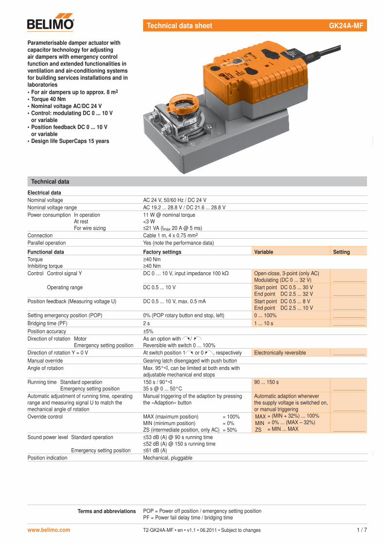
Parameterisable damper actuator with capacitor technology for adjusting air dampers with emergency control function and extended functionalities in ventilation and air-conditioning systems for building services installations and in laboratories• For air dampers up to approx. 8 m2
• Torque 40 Nm• Nominal voltage AC/DC 24 V• Control: modulating DC 0 ... 10 V
or variable• Position feedback DC 0 ... 10 V
or variable• Design life SuperCaps 15 years
Technical data
Electrical dataNominal voltage AC 24 V, 50/60 Hz / DC 24 VNominal voltage range AC 19.2 ... 28.8 V / DC 21.6 ... 28.8 VPower consumption In operation
At restFor wire sizing
11 W @ nominal torque<3 W≤21 VA (lmax 20 A @ 5 ms)
Connection Cable 1 m, 4 x 0.75 mm2
Parallel operation Yes (note the performance data)
Functional data Factory settings Variable SettingTorqueInhibiting torque
≥40 Nm≥40 Nm
Control Control signal Y DC 0 … 10 V, input impedance 100 k Open-close, 3-point (only AC)Modulating (DC 0 ... 32 V) .................................
Operating range DC 0.5 ... 10 V Start pointEnd point
DC 0.5 ... 30 VDC 2.5 ... 32 V .................................
Position feedback (Measuring voltage U) DC 0.5 ... 10 V, max. 0.5 mA Start pointEnd point
DC 0.5 ... 8 VDC 2.5 ... 10 V .................................
Setting emergency position (POP) 0% (POP rotary button end stop, left) 0 ... 100% .................................
Bridging time (PF) 2 s 1 ... 10 s .................................
Position accuracy ±5%Direction of rotation Motor
Emergency setting positionAs an option with / Reversible with switch 0 ... 100%
Direction of rotation Y = 0 V At switch position 1 or 0 , respectively Electronically reversible .................................
Manual override Gearing latch disengaged with push buttonAngle of rotation Max. 95° , can be limited at both ends with
adjustable mechanical end stopsRunning time Standard operation
Emergency setting position150 s / 90°35 s @ 0 ... 50°C
90 ... 150 s.................................
Automatic adjustment of running time, operating range and measuring signal U to match the mechanical angle of rotation
Manual triggering of the adaption by pressing the «Adaption» button
Automatic adaption whenever the supply voltage is switched on, or manual triggering .................................
Override control MAX (maximum position)MIN (minimum position)ZS (intermediate position, only AC)
= 100%= 0%= 50%
MAXMINZS
= (MIN + 32%) ... 100%= 0% ... (MAX – 32%)= MIN ... MAX .................................
Sound power level Standard operation
Emergency setting position
≤53 dB (A) @ 90 s running time≤52 dB (A) @ 150 s running time≤61 dB (A)
Position indication Mechanical, pluggable
Terms and abbreviations POP = Power off position / emergency setting positionPF = Power fail delay time / bridging time
2 / 7 T2-GK24A-MF • en • v1.1 • 06.2011 • Subject to changes www.belimo.com
Safety notes
!• The actuator is not allowed to be used outside the specified field of application, especially in
aircraft or in any other airborne means of transport.• It may only be installed by suitably trained personnel. Any legal regulations or regulations
issued by authorities must be observed during installation.• The device may only be opened at the manufacturer's site. It does not contain any parts that
can be replaced or repaired by the user.• The cable must not be removed from the device.• The device contains electrical and electronic components and is not allowed to be disposed
of as household refuse. All locally valid regulations and requirements must be observed.
Product features
Mode of operation The actuator moves the air damper to the desired operating position at the same time as thedesired operating position at the same time as theoperating position at the same time as the integrated capacitors are loaded. Interrupting the supply voltage causes the air damper to be rotated back into the emergency setting position by means of stored electrical energy.The actuator is controlled with a standard modulating signal of DC 0 ... 10 V and travels to the position defined by the control signal. The measuring voltage U serves for the electrical display of the damper position 0 ... 100%.
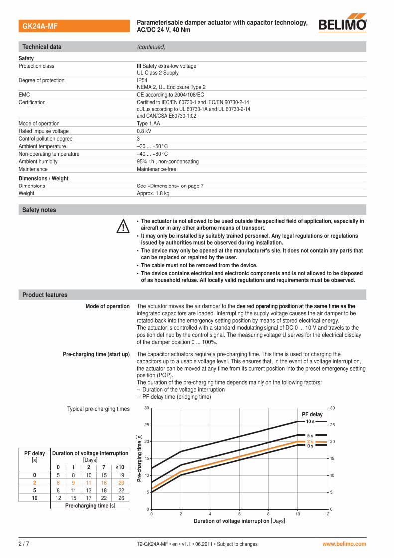
Pre-charging time (start up) The capacitor actuators require a pre-charging time. This time is used for charging the capacitors up to a usable voltage level. This ensures that, in the event of a voltage interruption, the actuator can be moved at any time from its current position into the preset emergency setting position (POP).The duration of the pre-charging time depends mainly on the following factors:– Duration of the voltage interruption– PF delay time (bridging time)
Typical pre-charging times
0
0
5
10
15
20
25
30
2 4 6 8 10 12
0 s
5 s
2 s
10 s
0
5
10
15
20
25
30
Technical data (continued)
SafetyProtection class III Safety extra-low voltage
UL Class 2 SupplyDegree of protection IP54
NEMA 2, UL Enclosure Type 2EMC CE according to 2004/108/ECCertification Certified to IEC/EN 60730-1 and IEC/EN 60730-2-14
cULus according to UL 60730-1A and UL 60730-2-14and CAN/CSA E60730-1:02
Mode of operation Type 1.AARated impulse voltage 0.8 kVControl pollution degree 3Ambient temperature –30 ... +50°CNon-operating temperature –40 ... +80°CAmbient humidity 95% r.h., non-condensatingMaintenance Maintenance-free
Dimensions / WeightDimensions See «Dimensions» on page 7Weight Approx. 1.8 kg
www.belimo.com T2-GK24A-MF • en • v1.1 • 06.2011 • Subject to changes 3 / 7
Product features (continued)
Calculation example:In the event of a voltage interruption of 3 days and a set bridging time (PF) of 5 s, the actuator requires a pre-charging time of 14 s (see graphic on page 2) after the voltage has been reconnected.
Delivery condition (capacitors) The actuator is completely discharged after delivery from the factory, which is why the actuator requires approximately 20 s pre-charging time before initial commissioning in order to bring the capacitors up to the required voltage level.
Parameterisable actuators The factory settings cover the most common applications. Input and output signals and other parameters can be altered with the BELIMO service tool MFT-P or with the ZTH-GEN adjustment and diagnostic tool.
Simple direct mounting Simple direct mounting on the damper spindle with a universal spindle clamp, supplied with an anti-rotation strap to prevent the actuator from rotating.
Manual override Manual override with push button possible (the gear is disengaged for as long as the button remains pressed down).
High operational reliability The actuator is overload-proof, requires no limit switches and automatically stops when the end stop is reached.
Home position / Start The clamp of the actuator is set ex-works to 0° .After the supply voltage has been applied, the actuator moves into the position defined by the control signal.
Direction of rotation switch When actuated, the direction of rotation switch changes the running direction in normal operation.The direction of rotation switch has no influence on the emergency setting position (POP) which has been set.
Emergency setting position (POP) rotary button
The «Emergency setting position» rotary button can be used to adjust the desired emergency setting position (POP) between 0 and 100% in 10% increments. The rotary button applies only to the adapted angle of rotation range of between 30 and 95° . No minimum or maximum set values are taken into account.In the event of a voltage interruption, the actuator will move into the selected emergency setting position, taking into account the bridging time.
Settings The rotary button must be set to the «Tool» position for retroactive settings of the emergency setting position with the BELIMO service tool MFT-P. Once the rotary button is set back to the range 0 … 100%, the manually set value will have positioning authority
Bridging time (PF) Voltage interruptions can be bridged up to a maximum of 10 s.In the event of a voltage interruption, the actuator will remain stationary in accordance with the set bridging time. If the voltage interruption is greater than the set bridging time, then the actuator will move into the selected emergency setting position (POP).The bridging time set ex-works is 2 s. This can be modified at the site of operations with the use of the BELIMO service tool MFT-P.
Settings The rotary button must not be set to the «Tool» position!Only the values need to be entered for retroactive adjustments of the bridging time with the BELIMO service tool MFT-P.
Accessories
Description Data sheet
Electrical accessories Auxiliary switch S..A.. T2 - S..A..Feedback potentiometer P..A.. T2 - P..A..Adapter Z-SPAIt is imperative that this adapter be ordered if an auxiliary switch or a feedback potentiometer is required and if at the same time the shaft adapter is installed on the rear side of the actuator (e.g. with short-spindle installation).BELIMO service tool MFT-PZTH-GEN adjustment and diagnostic toolPosition sensor SGA24, SGE24 and SGF24 T2 - SG..24Digital position indication ZAD24 T2 - ZAD24Room temperature controller CR24.. S4 - CR24-..
Mechanical accessories Various accessories T2 - Z-GM..A../GK..A..
4 / 7 T2-GK24A-MF • en • v1.1 • 06.2011 • Subject to changes www.belimo.com
Electrical installation
Wiring diagram
Y U
1 32 5
– +
T ~
Cable colours:1 = black2 = red3 = white5 = orange
Wiring diagram for parallel operation
1 32 5
– +
T ~
Y U1
1 32 5
U2
1 32 5
UX
Cable lengths
Y U
1 32 5
T ~A
C
L1
L2
Ltot
A = ActuatorC = Control unitL1 = Belimo connecting cable, 1 m (4 x 0.75 mm2)L2 = Customer cableLtot = Maximum cable length
Cross sectionL2
T
/
~Max. cable length
Ltot = L1 + L2
Example for DC
AC DC0.75 mm2 ≤40 m ≤20 m 1 m (L1) + 19 m (L2)1.00 mm2 ≤50 m ≤30 m 1 m (L1) + 29 m (L2)1.50 mm2 ≤80 m ≤45 m 1 m (L1) + 44 m (L2)2.50 mm2 ≤130 m ≤80 m 1 m (L1) + 79 m (L2)
NoteThere are no special restrictions on installation if the supply and data cable are routed separately.
LN
Y U
T
1 32 5
A
C
AC 24 V
AC 230 V
L1
A = ActuatorC = Control unitL1 = Belimo connecting cable, 1 m (4 x 0.75 mm2)
NoteConnect via safety isolation transformer. ! Control signal
Measuring voltage
NoteWhen several actuators are connected in parallel, the maximum cable length must be divided by the number of actuators.
Notes• A maximum of eight actuators can be connected
in parallel.• Parallel operation is permitted only on separated
axes.• It is imperative that the performance data be
observed with parallel operation.Actuator 1 Actuator 2 Actuator X