July 2016 Project: Customer: Engineer: Pump Manufacturer: Model GPY Full Service Reduced Voltage Wye-delta Open Electric Fire Pump Controller Technical Data Submittal Document Contents: • Data Sheets • Dimensional Data • Wiring Schematics • Field Connections Note: The drawings included in this package are for controllers covered under our standard offering. Actual AS BUILT drawings may differ from what is shown in this package.
Transcript
July 2016
Project: Customer: Engineer: Pump Manufacturer:
Model GPY Full Service Reduced Voltage
Wye-delta OpenElectric Fire Pump Controller
Technical Data Submittal Document
Contents:• Data Sheets • Dimensional Data• Wiring Schematics• Field Connections
Note: The drawings included in this package are for controllers covered under our standard offering. Actual AS BUILT drawings may differ from what is shown in this package.
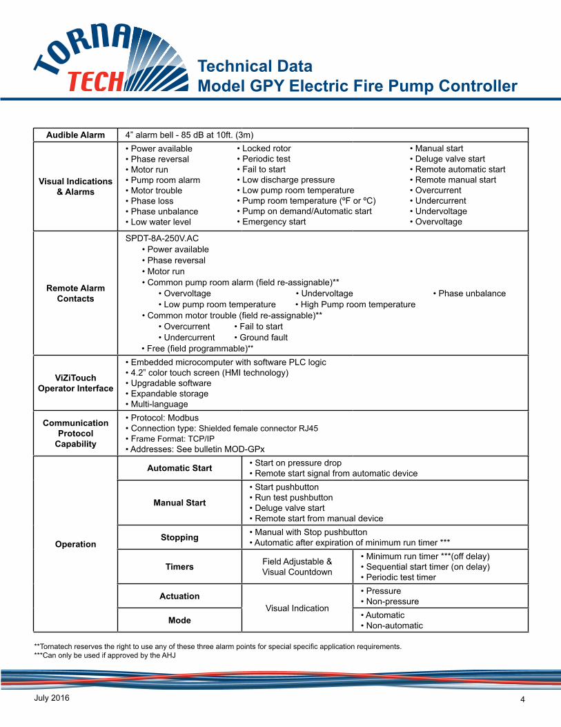
Technical Data Model GPY Electric Fire Pump Controller
July 2016 2
Standard,Listings,
Approvals andCertifications
Built to NFPA 20 (latest edition)
Underwriters Laboratory (UL) • UL218 - Fire Pump Controllers• CSA C22.2 No. 14 Industrial Control Equipment
FM Global Class 1321/1323New York City Accepted for use in the City of New York by the Department of BuildingsSeismic Certification See page 5 for detailsOptional□ CE Mark Various EN, IEC & CEE directives and standards
Enclosure
Protection Rating□ Standard: NEMA 2 (IP31)Optional□ NEMA 12□ NEMA 3□ NEMA 3R□ NEMA 4
*Please see Disconnecting Means details on page 3.
□ NEMA 4X-304 sst painted□ NEMA 4X-304 sst brushed finish□ NEMA 4X-316 sst painted□ NEMA 4X-316 sst brushed finish
□ IP54□ IP55□ IP65□ IP66
Paint Specifications• Red RAL3002• Powder coating• Glossy textured finish
From normalincoming power throughDisconnecting Means(IS/CB)*
Starting Method: Reduced VoltageWye-delta open
Typical Voltage Applied at Start: 100%Inrush Current: 33% of normal load currentStarting Torque: 33%Motor Type: Wye-deltaNo. of Contactors: 2 at 58%, 1 at 33% of motor FLCMin. ampacity of motor conductors: 6 at 125% x 58% of FLC
T2
T1
T31M
T4
T6
T52M
1S
3L2
1M
CR4
2M
CR5
1S
CR5 2M
1S
3L1
3L2
3L3
3L1
M
Across-the line starting
Locked rotor current
Full load current
Percent of motor speed (%)
Line
cur
rent
% o
f ful
l loa
d
20 40 60 80 100
600
Transition current
Wye delta starting
Open transition
210
GPY
Technical Data Model GPY Electric Fire Pump Controller
July 2016 3
Surge Suppression Surge arrestor rated to suppress surges above line voltage
Disconnecting Means
• Isolating switch and circuit breaker assembly:- Door interlocked in the ON position - Isolating switch rated not less than 115% of motor full load current- Circuit breaker continuous rating not less than 115% of motor full load current- Overcurrent sensing non-thermal type, magnetic only- Instantaneous trip setting of not more than 20 times the motor full load current
• Common flange mounted operating handle Service Entrance
Rating Suitable as service entrance equipment
Emergency Start Handle
• Flange mounted • Integrated limit switch• Pull and latch activation • Across the line start (direct on line)
Locked Rotor Protector
• Operate shunt trip to open circuit breaker • Trip between 8 and 20 seconds• Factory set at 600% of motor full load current
Electrical Readings
• Voltage phase to phase (normal power)• Amperage of each phase when motor is running
Pressure Readings
• Continuous system pressure display• Cut-in and Cut-out pressure settings
Pressure and Event recorder
• Pressure readings with date stamp• Event recording with date stamp• Under regular maintained operation, events can be stored in memory for up to 5 years.• Data viewable on operator interface display screen• Downloadable by USB port to external memory device
Pressure Sensing
• Pressure transducer and run test solenoid valve assembly for fresh water application• Pressure sensing line connection 1/2” Female NPT• Drain connection 3/8”• Rated for 0-500PSI working pressure (standard display at 0-300psi)• Externally mounted with protective cover
• Locked rotor• Periodic test• Fail to start• Low discharge pressure• Low pump room temperature • Pump room temperature (ºF or ºC)• Pump on demand/Automatic start• Emergency start
**Tornatech reserves the right to use any of these three alarm points for special specific application requirements.***Can only be used if approved by the AHJ
Technical Data Model GPY Electric Fire Pump Controller
July 2016 5
Seismic Certification
Seismic Certification Company
TRU Compliance, LLCA Tobalski Watkins Affiliate TWEI Project No.: 15014
Mounting details Rigid base and wall mounting
Seismic Information
Building Code
Test Criteria
Seismic Parameters SDS z/h IP AFLX-H ARIG-H AFLX-V ARIG-V
IBC 2015, CBC 2016
ICC-ES
AC156
ASCE 7-10 Chapter 13
2.0 1.0 1.5 3.20 2.40 1.33 0.53
3.2 0.0 1.5 3.20 1.28 2.13 0.85
0.1
1.0
10.0
0.1 1.0 10.0
Spe
ctra
l Res
pons
e A
ccel
erat
ion
(g)
Frequency, f (Hz)
RRS for Nonstructural Components Testing
Horiz. Level 1 Vert. Level 1
Notes:• Components are tested in accordance with ICC-ES AC156, IBC 2015 & CBC 2016. • OSHPD Special Seismic Certification Preapproval (OSP)
Technical Data Model GPY Electric Fire Pump Controller
July 2016 6
A4 Flow switch provision
A8 Foam pump application w/o pressure transducer and run test solenoid valve
A9 Low zone pump control function
A10 Middle zone pump control function
A11 High zone pump control function
A13 Non-pressure actuated controller w/o pressure transducer and run test solenoid valve
A16 Lockout/interlock circuit from equipment installed inside the pump room
B11
Built in alarm panel (120V.AC supervisory power) providing indication for:• Audible alarm & silence pushbutton for motor run, phase reversal, loss of phase.• Pilot lights for loss of phase & supervisory power available
B11BBuilt in alarm panel same as B11 but 220-240VAC supervisory power
B19A High motor temperature c/w thermoster relay and alarm contacts (Form C-SPDT)
B19B High motor temperature c/w PT100 relay and alarm contacts (Form C-SPDT)
4 Added Seismic Logo 19/08/153 General Revision 07/01/15
5 Modified Tornatech & Seismic Logo 14/04/16
Terminals Diagram and Sizing Built to the latest edition of the NFPA 20 standard
DD/MM/YYDESCRIPTIONREV.NYC
Dpt of BuildingApproved
Drawing number
Electric Fire Pump Controller Model:GPX
TD500 1/3 /EGPX-
Drawing for information only.Manufacturer reserves the right to modify this drawing without notice.For drawing for approval or installation, please contact manufacturer.
GPA, GPR & GPS
M
GndT1 T2 T3
1M
Incoming Power3 Phases
Bonding
Gnd L2L1IS
Ground
L3Power Terminals Notes:
1 - For proper wire sizing, refer to NFPA70 and NEC (USA) or CEC(Canada) or local code.2 - Controller suitable for service entrance in USA.3 - For more accurate motor connections refer to motor manufacturer ormotor nameplate.4 - Controller is phase sensitive. Incoming lines must be connected in ABCsequence.5 - Field wiring and lug sizes base on copper conductors only. Do not use aluminium conductors.
Models :
5 7.5 10 15 20 25
220 to 240
380 to 416
600
440 to 480
208 1x (10)
30 40 50 60
75 100 125 150 200 250 300 350 400 450 500
1x (14 to 10)
1x (14 to 10)
1x (14 to 10)
1x (12 to 10)
1x (14 to 10)
1x (14 to 10)
1x (12 to 10)
1x (10)
1x (10)
1x (14 to 10)
1x (12 to 10)
1x (10)
1x (8 to 2)
1x (8 to 2)
1x ( 10)
1x (10)
1x (8 to 2)
1x (6 to 2)
1x (6 to 2)
1x (10)
1x (8 to 2)
1x (8 to 2)
1x (4 to 1/0)
1x (4 to 1/0)
1x (8 to 2)
1x (8 to 2)
1x (6 to 2)
1x (4 to 1/0)
1x (3 to 1/0)
1x (8 to 2)
1x (6 to 2)
1x (6 to 1/0)
1x (3 to 1/0)
1x (2 to 1/0)
1x (6 to 2)
1x (6 to 2)
1x (4 to 1/0)
1x (1 to 3/0)
1x (1/0 to 3/0)
1x (6 to 2)
1x (4 to 1/0)
1x (3 to 1/0)
1x (2/0 to 3/0)
1x (3/0)
1x (4 to 1/0)
1x (3 to 1/0)
1x (3 to 1/0)
1x (3/0)
1x (4/0 to 300)
1x (3 to 1/0)
1x (1 to 2/0)
1x (1/0 to 3/0)
1x (250 to 300)
1x (300)
1x (1 to 2/0)
1x (2/0 to 3/0)
1x (3/0)
2x (2/0 to 300)
2x (2/0 to 300)
1x (3/0)
1x (2/0 to 3/0)
1x (250 to 300)
2x (3/0 to 300)
2x (4/0 to 300)
1x (3/0)
1x (4/0 to 300)
1x (300)
2x (4/0 to 300)
2x (250 to 300)
1x (250 to 300)
2x (1/0 to 300)
2x (3/0 to 300)
2x (350 to 500)
2x (2/0 to 300)
2x (3/0 to 300)
2x (4/0 to 300)
2x (3/0 to 300)
2x (4/0 to 300)
2x (300)
--------
--------
--------
2x (4/0 to 300)
2x (300)
--------
--------
2x (250 to 300)
--------
--------
2x (300)
--------
--------
--------
--------
220 to 240
380 to 416
600
440 to 480
208
5 7.5 10 15 20 25
220 to 240
380 to 416
600
440 to 480
208 1x (10 to 1/0)
30 40 50 60
75 100 125 150 200 250 300 350 400 450 500
1x (8 to 1/0)
1x (6 to 1/0)
1x (4 to 1/0)
1x (3 to 1/0)
1x (4 to 1/0)
1x (3 to 1/0)
1x (3 to 1/0)
1x (3 to 1/0)
1x (1 to 250)
1x (1/0 to 250)
1x (250 to 500)
1x (300 to 500)
1x (1 to 250)
1x (2/0 to 250)
1x (3/0 to 250)
1x (350 to 500)
1x (500)
1x (3/0 to 250)
1x (2/0 to 250)
1x (250)
2x (3/0 to 500)
2x (4/0 to 500)
1x (3/0 to 250)
1x (4/0 to 250)
1x (300 to 500)
2x (4/0 to 500)
2x (250 to 500)
1x (250 to 500)
1x (350 to 500)
2x (3/0 to 250)
1x (350 to 500)
2x (3/0 to 250)
2x (4/0 to 500)
2x (3/0 to 250)
2x (4/0 to 500)
2x (300 to 500)
--------
--------
--------
2x (4/0 to 500)
2x (300 to 500)
--------
--------
2x (250 to 500)
--------
--------
2x (300 to 500)
--------
--------
--------
--------
--------
220 to 240
380 to 416
600
440 to 480
208
5 " (127 mm) 8 " (203 mm)
12 " (305 mm)
5 " (127 mm) 8 " (203 mm) 12 " (305 mm)
1x (10 to 1/0)
1x (10 to 1/0)
1x (10 to 1/0)
1x (10 to 1/0)
1x (10 to 1/0)
1x (10 to 1/0)
1x (10 to 1/0)
1x (10 to 1/0)
1x (10 to 1/0)
1x (10 to 1/0)
1x (10 to 1/0)
1x (8 to 1/0)
1x (8 to 1/0)
1x (10 to 1/0)
1x (10 to 1/0)
1x (8 to 1/0)
1x (6 to 1/0)
1x (6 to 1/0)
1x (10 to 1/0)
1x (8 to 1/0)
1x (8 to 1/0)
1x (4 to 1/0)
1x (4 to 1/0)
1x (8 to 1/0)
1x (8 to 1/0)
1x (6 to 1/0)
1x (4 to 1/0)
1x (3 to 1/0)
1x (8 to 1/0)
1x (6 to 1/0)
1x (6 to 1/0)
1x (3 to 1/0)
1x (2 to 1/0)
1x (4 to 1/0)
1x (6 to 1/0)
1x (6 to 1/0)
1x (1 to 250)
1x (1/0 to 250)
1x (2/0 to 250)
1x (3/0 to 250)
1x (3/0 to 250)
1x (4/0 to 250)
2x (350 to 500)
2x (350 to 500)
2x (350 to 500)
2x (350 to 500)
2x (350 to 500)
Wiring Size for motor connection for Models GPA, GPR & GPS (AWG or MCM). TERMINALS T1 - T2 - T3
Voltage
Isolating Switch (IS) Field Wiring according to Bending Space (AWG or MCM). TERMINALS L1 - L2 - L3
Terminals Diagram and Sizing Built to the latest edition of the NFPA 20 standard
DD/MM/YYDESCRIPTIONREV.NYC
Dpt of BuildingApproved
Drawing number
Electric Fire Pump Controller Model:GPX
TD500 2/3 /EGPX-
Drawing for information only.Manufacturer reserves the right to modify this drawing without notice.For drawing for approval or installation, please contact manufacturer.
GPP
Notes:1 - For proper wire sizing, refer to NFPA70 and NEC (USA) or CEC(Canada) or local code.2 - Controller suitable for service entrance in USA.3 - For more accurate motor connections refer to motor manufacturer ormotor nameplate.4 - Controller is phase sensitive. Incoming lines must be connected in ABCsequence.5 - Field wiring and lug sizes base on copper conductors only. Do not use aluminium conductors.
Models :
M
GndT7 T8 T9
2M
Incoming Power3 Phases
Bonding
Gnd L2L1IS
Ground
L3
T1 T2 T3
1M
M
GndT6 T4 T5
2M
Incoming Power3 Phases
Bonding
Gnd L2L1IS
Ground
L3
T1 T2 T3
1M
Power Terminals
GPW & GPYModels :
5 7.5 10 15 20 25
220 to 240
380 to 416
600
440 to 480
208 1x (14 to 10)
30 40 50 60
75 100 125 150 200 250 300 350 400 450 500
1x (14 to 10)
1x (14 to 10)
1x (14 to 10)
1x (14 to 10)
1x (14 to 10)
1x (14 to 10)
1x (14 to 10)
1x (12 to 10)
1x (12 to 10)
1x (14 to 10)
1x (14 to 10)
1x (14 to 10)
1x (10)
1x (10)
1x (14 to 10)
1x (12 to 10)
1x (12 to 10)
1x (8 to 2)
1x (8 to 2)
1x (12 to 10)
1x (12 to 10)
1x (10)
1x (8 to 2)
1x (8 to 2)
1x (12 to 10)
1x (10)
1x (10)
1x (6 to 2)
1x (6 to 2)
1x (10)
1x (10 to 2)
1x (8 to 2)
1x (6 to 1/0)
1x (6 to 1/0)
1x (10 to 2)
1x (8 to 2)
1x (6 to 2)
1x (4 to 2/0)
1x (4 to 2/0)
1x (8 to 2)
1x (6 to 2)
1x (6 to 2)
1x (3 to 2/0)
1x (2 to 3/0)
1x (8 to 2)
1x (6 to 2)
1x (4 to 1/0)
1x (2 to 3/0)
1x (1 to 3/0)
1x (6 to 2)
1x (4 to 2/0)
1x (4 to 2/0)
1x (1/0 to 3/0)
1x (2/0 to 3/0)
1x (4 to 2/0)
1x (3 to 2/0)
1x (2 to 2/0)
1x (3/0)
1x (3/0)
1x (2 to 3/0)
1x (3 to 2/0)
1x (1/0 to 3/0)
1x (4/0 to 300)
1x (250 to 300)
1x (2 to 3/0)
1x (1/0 to 3/0)
1x (2/0 to 3/0)
1x (300)
2x (1/0 to 300)
1x (1/0 to 3/0)
1x (2/0 to 3/0)
2x (2/0 to 300)
1x (2/0 to 3/0)
1x (300)
1x (300)
2x (2/0 to 300)
--------
--------
--------
1x (250 to 300)
2x (1/0 to 300)
--------
--------
1x (300)
2x (2/0 to 300)
--------
--------
2x (1/0 to 300)
--------
--------
2x (2/0 to 300)
--------
--------
--------
220 to 240
380 to 416
600
440 to 480
208
5 7.5 10 15 20 25
220 to 240
380 to 416
600
440 to 480
208 1x (10 to 1/0)
30 40 50 60
75 100 125 150 200 250 300 350 400 450 500
1x (8 to 1/0)
1x (6 to 1/0)
1x (4 to 1/0)
1x (3 to 1/0)
1x (4 to 1/0)
1x (3 to 1/0)
1x (3 to 1/0)
1x (3 to 1/0)
1x (1 to 250)
1x (1/0 to 250)
1x (250 to 500)
1x (300 to 500)
1x (1 to 250)
1x (2/0 to 250)
1x (3/0 to 250)
1x (350 to 500)
1x (500)
1x (3/0 to 250)
1x (2/0 to 250)
1x (250)
2x (3/0 to 500)
2x (4/0 to 500)
1x (3/0 to 250)
1x (4/0 to 250)
1x (300 to 500)
2x (4/0 to 500)
2x (250 to 500)
1x (250 to 500)
1x (350 to 500)
2x (3/0 to 250)
1x (350 to 500)
2x (3/0 to 250)
2x (4/0 to 500)
2x (3/0 to 250)
2x (4/0 to 500)
2x (300 to 500)
--------
--------
--------
2x (4/0 to 500)
2x (300 to 500)
--------
--------
2x (250 to 500)
--------
--------
2x (300 to 500)
--------
--------
--------
--------
--------
220 to 240
380 to 416
600
440 to 480
208
5 " (127 mm) 8 " (203 mm)
12 " (305 mm)
5 " (127 mm) 8 " (203 mm) 12 " (305 mm)
1x (10 to 1/0)
1x (10 to 1/0)
1x (10 to 1/0)
1x (10 to 1/0)
1x (10 to 1/0)
1x (10 to 1/0)
1x (10 to 1/0)
1x (10 to 1/0)
1x (10 to 1/0)
1x (10 to 1/0)
1x (10 to 1/0)
1x (8 to 1/0)
1x (8 to 1/0)
1x (10 to 1/0)
1x (10 to 1/0)
1x (8 to 1/0)
1x (6 to 1/0)
1x (6 to 1/0)
1x (10 to 1/0)
1x (8 to 1/0)
1x (8 to 1/0)
1x (4 to 1/0)
1x (4 to 1/0)
1x (8 to 1/0)
1x (8 to 1/0)
1x (6 to 1/0)
1x (4 to 1/0)
1x (3 to 1/0)
1x (8 to 1/0)
1x (6 to 1/0)
1x (6 to 1/0)
1x (3 to 1/0)
1x (2 to 1/0)
1x (4 to 1/0)
1x (6 to 1/0)
1x (6 to 1/0)
1x (1 to 250)
1x (1/0 to 250)
1x (2/0 to 250)
1x (3/0 to 250)
1x (3/0 to 250)
1x (4/0 to 250)
2x (350 to 500)
2x (350 to 500)
2x (350 to 500)
1x (4/0 to 300)
1x (4/0 to 300)
1x (4/0 to 300)
Wiring Size for motor connection for Models GPP, GPW & GPY (AWG or MCM). TERMINALS T1 - T2 - T3 - T4 - T5 - T6 - T7 - T8 - T9
HP
HP
HP
HP
2x (3/0 to 300)
2x (3/0 to 350)
2x (4/0 to 350)
2x (4/0 to 350) 2x (4/0 to 350)
2x (3/0 to 350) 2x (4/0 to 350)
2x (400 to 500)
2x (400 to 600)
2x (500 to 600)
2x (500 to 600) 2x (600)
2x (400 to 600) 2x (500 to 600)
2x (400 to 500)
Voltage
Isolating Switch (IS) Field Wiring according to Bending Space (AWG or MCM). TERMINALS L1 - L2 - L3
Terminals Diagram and Sizing Built to the latest edition of the NFPA 20 standard
DD/MM/YYDESCRIPTIONREV.NYC
Dpt of BuildingApproved
Drawing number
Electric Fire Pump Controller Model:GPX
TD500 3/3 /EGPX-
Control Terminals (I/O board)
Close to start pump 2324 J25
Remote Manual Start
Open to start pump 2728 J25
Automatic Start
Signal
DelugeValve Open to start pump 29
30 J25
Deluge Valve
Signal
Water ReservoirLow Close to signal alarm 31
32 J25
Water Reservoir Low
Signal
Flow / ZoneStart / Stop 33
34 J25
Flow / Zone
(I/O board)
Close to signal alarm
SignalLockout Close to block start 25
26 J25
Lockout
J1If used, remove jumper J1
J2If used, remove jumper J2
Field Connections for External Devices
RunningMotor
TroubleMotor
Reversal Phase
AvailablePower
Remote Alarm Terminals (I/O board)
(Fail Safe)
AlarmRoomPump
J19 - 14J19 - 11J19 - 12
Normally closedOpens to alarm
Closes to alarmNormally open
J40 - 14J40 - 11J40 - 12
Normally openCloses to alarm
Opens to alarmNormally closed
J42 - 14J42 - 11J42 - 12
Normally closedOpens to alarm
Closes to alarmNormally open
J37 - 14J37 - 11J37 - 12
Normally closedOpens to alarm
Closes to alarmNormally open
J39 - 14J39 - 11J39 - 12
Normally closedOpens to alarm
Closes to alarmNormally open
TB1
TB2
TB3
TB4
MO
TOR
RU
N
Programmable)(Field*
J41 - 14J41 - 11J41 - 12
Normally closedOpens to alarm
Closes to alarmNormally open
TB5
(RE-ASSIGNABLE)
(RE-ASSIGNABLE)
*Not Available in GPS Models
Drawing for information only.Manufacturer reserves the right to modify this drawing without notice.For drawing for approval or installation, please contact manufacturer.


![GPY NR17-26 Rex Brommecker as Exp Director FINAL[1] · Microsoft Word - GPY NR17-26 Rex Brommecker as Exp Director FINAL[1].DOCX Created Date: 20171204210912Z ...](https://static.documents.pub/doc/80x56/5bf4a5c609d3f2d24c8b4e1f/gpy-nr17-26-rex-brommecker-as-exp-director-final1-microsoft-word-gpy-nr17-26.jpg)


