Product description & assembly instruction TurbFly® – snow and sand protection with brushes Valid from Author Version Page 2017.01.01 Mats Wickström 2 1(21) Product description and assembly instruction. Snow and sand protection with brushes.
Transcript
Product description & assembly instruction TurbFly® – snow and sand protection with brushes
Valid from Author Version Page
2017.01.01 Mats Wickström 2 1(21)
Product description and
assembly instruction.
Snow and sand protection with
brushes.
Product description & assembly instruction TurbFly® – snow and sand protection with brushes
Valid from Author Version Page
2017.01.01 Mats Wickström 2 2(21)
Index
1 System description TurbFly® ..................................................................... 3
1.1 Type of applications ................................................................................................................... 4
2.1 Introduction to assembly ............................................................................................................ 5 2.2 Assembly under tie bolts, Fastener galvanized steel ....................................................................... 6 2.3 Assembly with RailFootBracket, sets of type xxRF (item no. 129785) ............................................... 8 2.4 Assembly of full plastic brush system (item 595xx) ...................................................................... 10 2.5 Installation of End Fittings (item 59255-1), all switch types .......................................................... 12 12 2.6 Installations by activator units, or other” Special” cases ............................................................... 13 2.7 Installation of joint fittings ........................................................................................................ 14 2.8 Sets with brush length 2350 mm ............................................................................................... 15 2.9 Sets FULL PLASTIC BRUSHES with brush length 1150 mm ............................................................ 17 2.10 Components, bulk packed (no sets) / spare parts ........................................................................ 18
Product description & assembly instruction TurbFly® – snow and sand protection with brushes
Valid from Author Version Page
2017.01.01 Mats Wickström 2 3(21)
1 System description TurbFly®
The product has been available on market since 2003, and in the early days named “SnowProtec” and
has been installed at more than 1000 turnouts, so far mainly within Scandinavia. There is also a north
American version of the system sold under the same brand, but then only on the American continent.
TurbFly® has the main function in its task to protect turnouts from drifting snow or sand (or other
wind born disturbing materials), with the function secure high availability and functionality of the
turnout.
The system works together with electrical- or gas- heated heaters for switches.
Snow protection in the form of wind shield for tongue and movable crossing helps to maintain heat
from the switch heating and minimize drifting snow coming into the switch. With this solution
minimize or completely avoid manual clearing from snow and ice. Snow protection and heating are
completing each other in the task maintaining functionality of switches even in difficult weather
conditions. Works very well in sandy conditions too.
All brushes have the same total height, 165 mm. Depending on desired length for supplies, different
wooden boxes are available, most common is
2350 mm (delivered in EUR long pallet 800x2400x360)
The brush fasteners are rigidly designed, completely made from galvanized steel, completed with
galvanized screw and washer, all is designed for several years’ outdoor use.
Complementary fasteners have been developed and produced to meet different requirements for
assembly situations. One example is the rail foot bracket that has been developed to make it possible
to mount the protection system without being limited to the positions of the rail ties. The rail foot
bracket can be placed where ever wanted between the ties and are gripping around the entire rail foot.
All components are made from galvanized steel.
Product description & assembly instruction TurbFly® – snow and sand protection with brushes
Valid from Author Version Page
2017.01.01 Mats Wickström 2 4(21)
1.1 Type of applications
Depending on where the TurbFly®-system would be mounted, there are different types of fasteners
and brackets available as well as different types of brushes (brush with metal back or brush completely
made out of plastic).
The different fastening methods are described in different chapters of this document.
Non electrified tracks or tracks with overhead power supply lines
Power supply with
conductor rail
(3:rd rail)
Mounting in tie bolts Mounting with rail foot bracket Mounting of full plastic
brush system
The original way of mounting
Least number of needed
components, therefore price
vice the most cost effective
option.
Limited choice of places for
Fasteners, limitation to places
where ties and tie bolts are
available for fixation.
Gives much more
flexibility for the assembly.
Easier and faster to decide
and fit into optimized
locations for fasteners.
Fixing of rail remains
untouched and
uninfluenced.
Price vice a higher purchase
cost but much more rational
during assembly work and
maintenance.
Designed to be used
in applications with
conductor rail, where
long metal parts not
are allowed for
safety reasons.
Brush item (Strip) is
completely made
from plastic
material, and then
also fully electrically
insulated. Only the
“short” Fasteners are
made of metal.
Product description & assembly instruction TurbFly® – snow and sand protection with brushes
Valid from Author Version Page
2017.01.01 Mats Wickström 2 5(21)
2 Assembly
2.1 Introduction to assembly
Before starting the physical assembly, you start with arranging the components along the switch
tongue to estimate where the brush sections fits the best and then where the fasteners will be
positioned. When making the real assembly then all necessary components already are placed close
by, to make the step fast and easy, without further walking needed to get more items for assembly.
When starting the positioning of the first brush section it should be placed where it´s end goes beyond
the end of the movable switch-tongue with approximately 1 to 1.5 meter. Distance between each tie
(normally made of wood or concrete) is theoretically 600 mm, but can differ depending of switch-type.
Exact positions are not possible to define, and that’s the reason why common sense is needed to decide
final position of the sections.
1-1,5 m
Assembly along full length of switch tongue +1 m/side Assembly along movable crossing
TurbFly brushes marked with red lines
M10 X 60 = 12Nm
M14 = 30Nm
M10 x 25 = 30Nm
Product description & assembly instruction TurbFly® – snow and sand protection with brushes
Valid from Author Version Page
2017.01.01 Mats Wickström 2 6(21)
2.2 Assembly under tie bolts, Fastener galvanized steel
For assembly under existing tie bolts, after having defined the positions for the brush-sections, one has
to loosen every second bolt (at distance cc 1200 mm). The fasteners consisting of two pieces can
preferably be preassembled and put on each predestined position.
Loosen bolt and fix the fork piece between tie bolt and
baseplate.
Continue to assemble all fasteners fork pieces. It´s
important to make the assembly and fixing in line with
the rail.
Place the upper white brush into the fork piece,
assemble the U-shaped holder into the fork-piece,
mount the washer and the screw, turn the screw firm –
preferably with an electric screwdriver.
Push down the lower black brush behind the upper
white brush and tighten the screw.
When used in installation protecting from sandy
conditions, only the upper part is used.
Brushes should always be assembled along the whole
extent of the tongue and also pass further beyond where
the tongue ends with approximately 1 meter (~3 feet) on
both sides to give the best protection.
Fasteners made of galvanized steel are fully compatible
and exchangeable with the fasteners made from
aluminum. Nevertheless, it is preferable to use the same kind of fasteners within the very same
assembly, either version1 or version2.
Product description & assembly instruction TurbFly® – snow and sand protection with brushes
Valid from Author Version Page
2017.01.01 Mats Wickström 2 7(21)
Then install the downward black brush and fit into the outer fitting part, fit the through bolt and
tighten the fitting with the through M10 screw (wrench 17 mm).
When installing with steel fasteners there is also possible
to do splicing of brushes inside the brackets pinch points
(optimally aligned with the position of screw).
The beginning and end of the complete brush-
section is done with brushes that pass through
the whole bracket with about 10-20 mm.
If through pass is greater than 250 mm end
brackets should be assembled (itemno. 59255),
see chapter 2:7.
For each brush with length >= 2000 mm it
should be mounted with 3 fixing points. Shorter
brushes is enough with 2 fixing points.
Product description & assembly instruction TurbFly® – snow and sand protection with brushes
Valid from Author Version Page
2017.01.01 Mats Wickström 2 8(21)
2.3 Assembly with RailFootBracket, sets of type xxRF
(item no. 129785)
If you choose not to install in the ties bolt, you can instead use Rail Foot Brackets. The bracket gives
great freedom of choice in the placement of attachment points. The bracket consists of two parts and
they can when mounting be pre-placed next to switch with a distance of cc 1200 mm. For each brush
section is needed three brackets (at the brushes of length 2350 mm - 3 x “no of brushes”)
Before Brush assembly (Section 2:2 / 2:3) is
performed the Rail Foot Brackets, that grips the
entire underside of the rail, must be mounted.
Select the position of holes for fastening screws
depending on the rail foot width. Bracket is
mounted on the rail foot without being fully
dragged down, in that way you can move the
bracket sideways to be aligned to the final
placement during installation.
When all Rail Foot Brackets is seated, continue the
assembly as normal under Section 2:2 / 2:3.
Tighten M14 bolt (22mm wrench/socket) in the
Rail Foot Brackets.
Finally tighten all the M10 screws on all brackets
(wrench/socket 17 mm).
Torques:
M14 x 30 = 30Nm
M10 x 25 = 30Nm
M10 x 60 = 12Nm
Product description & assembly instruction TurbFly® – snow and sand protection with brushes
Valid from Author Version Page
2017.01.01 Mats Wickström 2 9(21)
1:
Make sure that the bracket
sits in on the rail correct.
2:
After that the bracket and the top part are
in correct position, tighten the bolts but
leave a play of 2-3 mm.
3:
Put pressure on the top part with you thumb at
the end of it, before you tighten the screws. By
doing so, the bracket will be slightly tilted and
thereby grabs the rail better. A power tool is
recommended to use here.
4:
After that the installation of the bracket is finished,
control that the bracket can’t be moved in any direction.
If so, redo as described above.
M10 X 60 = 12Nm
M14 = 30Nm
M10 x 25 = 30Nm
Product description & assembly instruction TurbFly® – snow and sand protection with brushes
Valid from Author Version Page
2017.01.01 Mats Wickström 2 10(21)
2.4 Assembly of full plastic brush system (item 595xx)
TurbFly® with brush completely made of plastic are used primarily in connection with applications
where there are so-called conductor rail or 3: rd rail. The brush is made of plastic in order not to be a
leader, because otherwise there is a large short circuit risk with risk for personal injury.
The installation is done with brushes of length 1150 mm.
The upward standing brush is blue and the downward
directed brush is of soft white material for the flexible seal
against the ballast-filled ground.
Start by placing brush sections along the length of the
switch tongue. Mount RailFootBracket (described in section
2.3) at appropriate positions. The distance between each
bracket will be about 800 mm. At the transition between
sections double Fasteners will be applied to allow easy
assembly and disassembly of entire brush sections.
Each brush section is to be preassembled with 2 brackets
that are pushed on from the side. Both blue and white brush
is mounted in the 2 mounting brackets.
At joints double brackets will come next to each other.
Product description & assembly instruction TurbFly® – snow and sand protection with brushes
Valid from Author Version Page
2017.01.01 Mats Wickström 2 11(21)
After the complete brush package has been secured in place
at the rail, and all brackets are tightened, the assembly ends
by mounting 1-2 self-tapping screws (item 59245) which are
screwed down through the plastic body and the screw tip
should meet in a hole through the fitting.
The screw is mounted to lock the brush in the longitudinal
direction.
Product description & assembly instruction TurbFly® – snow and sand protection with brushes
Valid from Author Version Page
2017.01.01 Mats Wickström 2 12(21)
2.5 Installation of End Fittings (item 59255-1), all switch types
Push on end fitting on the two assembled brushes.
There are four end fittings in the kit and they must be
used at the beginning and end of brush assembly.
The end fitting must be pressed firmly to be exactly
fitted towards the brush.
Then screw the 2 screws (2 pieces for each end
fitting) from the side.
NOTE! NEVER screw the screws from under or
from above. This leads the screw to press the brush
bristles out from the backing tape and damage the
brush.
Product description & assembly instruction TurbFly® – snow and sand protection with brushes
Valid from Author Version Page
2017.01.01 Mats Wickström 2 13(21)
2.6 Installations by activator units, or other” Special” cases
The End Fitting (item 59255-1) or Fastener (item 59235-1) is useful for making various types of
special assemblies. For example, to pass through switch activators, etc. that you want to pass with the
brushes, but still be able to open or access without dismantling the entire brush package.
The End Fitting is fastened into the brush end and bolted to the
base or the door with the help of the height-adjustable angle
bracket.
In very low mounting cases, even the lower brush could be cut
with a suitable profile cut for easier mounting
Example of early assembly case
When cutting off brush you should always let ends be squeezed
together in a vice or similar to secure the internal tying thread of
the brush is kept in place.
Remember that the free ends, always shall be covered with end
fittings. Complete mounting set, are sold under the article number
59950 and ordered separately.
Mounting set 59950 consist of:
4 pcs angle bracket (item no. 59235)
8 pcs end fitting (itemno.59255)
2 pcs brush, 600 mm (white, item no. 59222)
2 pcs brush, 600 mm (black, item no. 59212)
Complete with 25 mm long M10 screws and washers for
assembly on metal sheets.
Product description & assembly instruction TurbFly® – snow and sand protection with brushes
Valid from Author Version Page
2017.01.01 Mats Wickström 2 14(21)
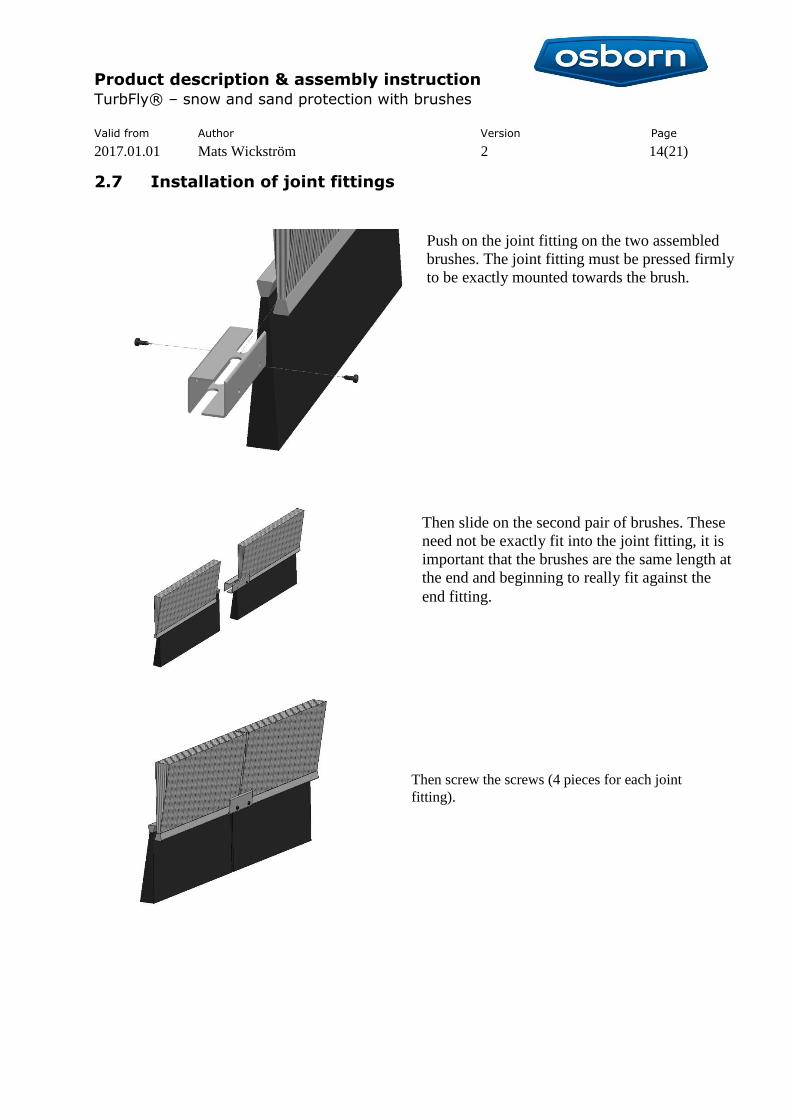
2.7 Installation of joint fittings
Push on the joint fitting on the two assembled
brushes. The joint fitting must be pressed firmly
to be exactly mounted towards the brush.
Then slide on the second pair of brushes. These
need not be exactly fit into the joint fitting, it is
important that the brushes are the same length at
the end and beginning to really fit against the
end fitting.
Then screw the screws (4 pieces for each joint
fitting).
Product description & assembly instruction TurbFly® – snow and sand protection with brushes