28
Technical description Atec www.thermia.com

Thermia Värmepumpar is not liable or bound by warranty if theseinstructions are not adhered to during installation or service.
The English language is used for the original instructions.Other languages are a translation of the original instructions.(Directive 2006/42/EC)
© Copyright Thermia Värmepumpar

Table of Contents
1 Atec heat pump . . . . . . . . . . . . . . . . . . . . . . . . . . . . . . . . . . . . . . . . . . . . . . . . . . . . . . . . . . . . . . . . . 41.1 Principle description . . . . . . . . . . . . . . . . . . . . . . . . . . . . . . . . . . . . . . . . . . . . . . . . . . . . . . . . . . . 41.2 Heating . . . . . . . . . . . . . . . . . . . . . . . . . . . . . . . . . . . . . . . . . . . . . . . . . . . . . . . . . . . . . . . . . . . 41.3 Hot water function . . . . . . . . . . . . . . . . . . . . . . . . . . . . . . . . . . . . . . . . . . . . . . . . . . . . . . . . . . . . 51.4 Defrost function . . . . . . . . . . . . . . . . . . . . . . . . . . . . . . . . . . . . . . . . . . . . . . . . . . . . . . . . . . . . . . 61.5 Cooling function . . . . . . . . . . . . . . . . . . . . . . . . . . . . . . . . . . . . . . . . . . . . . . . . . . . . . . . . . . . . . . 71.6 Check and safety functions . . . . . . . . . . . . . . . . . . . . . . . . . . . . . . . . . . . . . . . . . . . . . . . . . . . . . . . 8
2 Heat pump data, components . . . . . . . . . . . . . . . . . . . . . . . . . . . . . . . . . . . . . . . . . . . . . . . . . . . . . . . . 122.1 Heat pump data, components . . . . . . . . . . . . . . . . . . . . . . . . . . . . . . . . . . . . . . . . . . . . . . . . . . . . . 12
3 Important parameters . . . . . . . . . . . . . . . . . . . . . . . . . . . . . . . . . . . . . . . . . . . . . . . . . . . . . . . . . . . . . 143.1 Heat production - calculating . . . . . . . . . . . . . . . . . . . . . . . . . . . . . . . . . . . . . . . . . . . . . . . . . . . . . 143.2 CURVE . . . . . . . . . . . . . . . . . . . . . . . . . . . . . . . . . . . . . . . . . . . . . . . . . . . . . . . . . . . . . . . . . . . . 143.3 ROOM . . . . . . . . . . . . . . . . . . . . . . . . . . . . . . . . . . . . . . . . . . . . . . . . . . . . . . . . . . . . . . . . . . . . 153.4 Adjusting the heat curve a -5°C, 0°C and 5°C . . . . . . . . . . . . . . . . . . . . . . . . . . . . . . . . . . . . . . . . . . . . 163.5 HEAT STOP . . . . . . . . . . . . . . . . . . . . . . . . . . . . . . . . . . . . . . . . . . . . . . . . . . . . . . . . . . . . . . . . . 163.6 MIN and MAX . . . . . . . . . . . . . . . . . . . . . . . . . . . . . . . . . . . . . . . . . . . . . . . . . . . . . . . . . . . . . . . . 163.7 TEMPERATURES . . . . . . . . . . . . . . . . . . . . . . . . . . . . . . . . . . . . . . . . . . . . . . . . . . . . . . . . . . . . . . 173.8 INTEGRAL . . . . . . . . . . . . . . . . . . . . . . . . . . . . . . . . . . . . . . . . . . . . . . . . . . . . . . . . . . . . . . . . . . 173.9 HYSTERESIS . . . . . . . . . . . . . . . . . . . . . . . . . . . . . . . . . . . . . . . . . . . . . . . . . . . . . . . . . . . . . . . . . 193.10 DEFR CURVE . . . . . . . . . . . . . . . . . . . . . . . . . . . . . . . . . . . . . . . . . . . . . . . . . . . . . . . . . . . . . . . . 193.11 Defrost function . . . . . . . . . . . . . . . . . . . . . . . . . . . . . . . . . . . . . . . . . . . . . . . . . . . . . . . . . . . . . . 63.12 Concrete drying . . . . . . . . . . . . . . . . . . . . . . . . . . . . . . . . . . . . . . . . . . . . . . . . . . . . . . . . . . . . . . 22
4 Technical data . . . . . . . . . . . . . . . . . . . . . . . . . . . . . . . . . . . . . . . . . . . . . . . . . . . . . . . . . . . . . . . . . . 244.1 Atec . . . . . . . . . . . . . . . . . . . . . . . . . . . . . . . . . . . . . . . . . . . . . . . . . . . . . . . . . . . . . . . . . . . . . . 24
Technical description Atec
Thermia Värmepumpar VMIFM102 3
1 Atec heat pump
1.1 Principle description
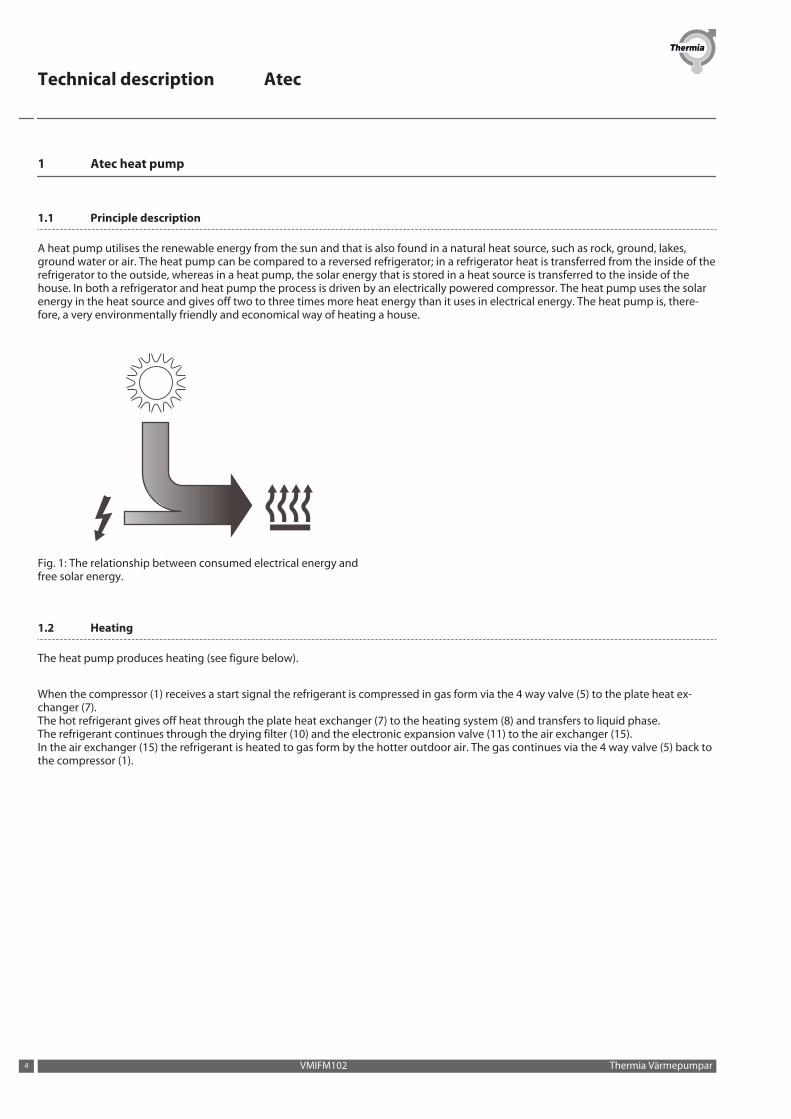
A heat pump utilises the renewable energy from the sun and that is also found in a natural heat source, such as rock, ground, lakes,ground water or air. The heat pump can be compared to a reversed refrigerator; in a refrigerator heat is transferred from the inside of therefrigerator to the outside, whereas in a heat pump, the solar energy that is stored in a heat source is transferred to the inside of thehouse. In both a refrigerator and heat pump the process is driven by an electrically powered compressor. The heat pump uses the solarenergy in the heat source and gives off two to three times more heat energy than it uses in electrical energy. The heat pump is, there-fore, a very environmentally friendly and economical way of heating a house.
Fig. 1: The relationship between consumed electrical energy andfree solar energy.
1.2 Heating
The heat pump produces heating (see figure below).
When the compressor (1) receives a start signal the refrigerant is compressed in gas form via the 4 way valve (5) to the plate heat ex-changer (7).The hot refrigerant gives off heat through the plate heat exchanger (7) to the heating system (8) and transfers to liquid phase.The refrigerant continues through the drying filter (10) and the electronic expansion valve (11) to the air exchanger (15).In the air exchanger (15) the refrigerant is heated to gas form by the hotter outdoor air. The gas continues via the 4 way valve (5) back tothe compressor (1).
Technical description Atec
VMIFM102 Thermia Värmepumpar4

3
2
1
1918
1715
14
16
1113
12
10
9
8
7 6
5
4
Fig. 2: The refrigerant circuit during heating production
Position Description Position Description1 Compressor 11 Electronic expansion valve2 Operating pressure switch 12 Non-return valve3 High pressure switch 13 Solenoid4 Discharge pipe sensor 14 Refrigerant sensor 25 Four-way valve 15 Air exchanger (evaporator)6 Heating system (cold return line) 16 Fan7 Plate heat exchanger (condenser) 17 Refrigerant sensor 18 Heating system (hot supply line) 18 Pressure transmitter9 Receiver 19 Temperature transmitter10 Drying filter
The heat pump can produce heat for heating (house, pool), hot water and cooling. The hot water requirement is prioritised before theheating requirement and cooling requirement. The heating requirement is calculated from the outdoor temperature and the heat curve.
1.3 Hot water function
The water heater is equipped with a TWS coil (Tap Water Stratificator). The hot water is led from the heat pump through the water heaterin the TWS coil from the top down. In this way the upper section of the water heater, where the hot water is tapped from, is alwaysheated first.
Heating the hot water in the water heater is not stopped by the temperature but via the pressure in the refrigerant circuit of the heatpump unit. The operating pressure switch on the pressure pipe breaks at 28.5 bar. This means that heat pumps in different outputclasses may have slightly different peak temperatures for hot water. As a rule the peak temperature is between 54 – 58°C in a 180-litrewater heater. Thanks to the design of the water heater and the TWS coil the hot water layers itself so that the hottest water is always atthe top of the water heater and the cooler water at the bottom.
Technical description Atec
Thermia Värmepumpar VMIFM102 5
Two sensors indicate the present temperature of the hot water to the heat pump controls. A top water sensor that is located in the topof the water heater, and a hot water sensor located approx 50 cm up from the bottom of the water heater. Both the sensor valuesare ”weighted” where the hot water sensor influence is 65 % (factory setting, can be changed if necessary).This means that if the start value for hot water production is set to 40°C the heat pump need not necessarily start hot water productionwhen the hot water sensor displays 40°C but also makes reference to what temperature the peak water sensor displays. If it is still veryhot at the top of the water heater the start of hot water production will be delayed.
With anti-legionella operation, when the immersion heater heats the water heater to 60°C to prevent growth of legionella bacteria, thepeak water sensor temperature has no impact, only the hot water sensor has control. Anti-legionella is factory set as top heating intervalevery 7th day.
1.4 Defrost function
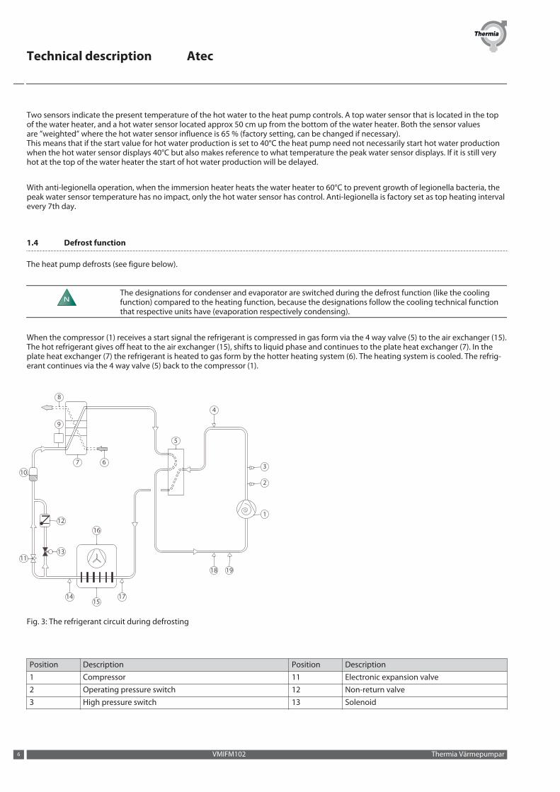
The heat pump defrosts (see figure below).
NThe designations for condenser and evaporator are switched during the defrost function (like the coolingfunction) compared to the heating function, because the designations follow the cooling technical functionthat respective units have (evaporation respectively condensing).
When the compressor (1) receives a start signal the refrigerant is compressed in gas form via the 4 way valve (5) to the air exchanger (15).The hot refrigerant gives off heat to the air exchanger (15), shifts to liquid phase and continues to the plate heat exchanger (7). In theplate heat exchanger (7) the refrigerant is heated to gas form by the hotter heating system (6). The heating system is cooled. The refrig-erant continues via the 4 way valve (5) back to the compressor (1).
3
2
1
1918
1715
14
16
1113
12
10
9
8
7 6
5
4
Fig. 3: The refrigerant circuit during defrosting
Position Description Position Description1 Compressor 11 Electronic expansion valve2 Operating pressure switch 12 Non-return valve3 High pressure switch 13 Solenoid
Technical description Atec
VMIFM102 Thermia Värmepumpar6
Position Description Position Description4 Discharge pipe sensor 14 Refrigerant sensor 25 Four-way valve 15 Air exchanger (condenser)6 Heating system (hot return line) 16 Fan7 Plate heat exchanger (evaporator) 17 Refrigerant sensor 18 Heating system (cold supply line) 18 Pressure transmitter9 Receiver 19 Temperature transmitter10 Drying filter
Defrosting is initiated by low temperature in the refrigerant circuit after the air exchanger and, among other things, is dependent onoutdoor temperature, humidity and operating time. The length of defrosting varies depending on the extent of freezing of the air ex-changer.
Defrost continues until the air heat exchanger is free of ice and the temperature after the air exchanger has risen to the desired tempera-ture. After completed defrosting the heat pump returns to the operating mode before defrosting.
During defrosting the heat pump retrieves energy from the house's heating system. The water volume in the heating system can beincreased by installing a buffer tank. The buffer tank can also act as a surge tank.
1.5 Cooling function
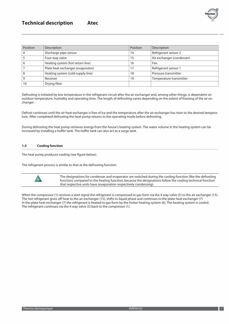
The heat pump produces cooling (see figure below).
The refrigerant process is similar to that at the defrosting function.
NThe designations for condenser and evaporator are switched during the cooling function (like the defrostingfunction) compared to the heating function, because the designations follow the cooling technical functionthat respective units have (evaporation respectively condensing).
When the compressor (1) receives a start signal the refrigerant is compressed in gas form via the 4 way valve (5) to the air exchanger (15).The hot refrigerant gives off heat to the air exchanger (15), shifts to liquid phase and continues to the plate heat exchanger (7).In the plate heat exchanger (7) the refrigerant is heated to gas form by the hotter heating system (6). The heating system is cooled.The refrigerant continues via the 4 way valve (5) back to the compressor (1).
Technical description Atec
Thermia Värmepumpar VMIFM102 7
3
2
1
1918
1715
14
16
1113
12
10
9
8
7 6
5
4
Fig. 3: Refrigerant circuit during cooling production
Position Description Position Description1 Compressor 11 Electronic expansion valve2 Operating pressure switch 12 Non-return valve3 High pressure switch 13 Solenoid4 Discharge pipe sensor 14 Refrigerant sensor 25 Four-way valve 15 Air exchanger (condenser)6 Heating system (hot return line) 16 Fan7 Plate heat exchanger (evaporator) 17 Refrigerant sensor 18 Heating system (cold supply line) 18 Pressure transmitter9 Receiver 19 Temperature transmitter10 Drying filter
The cooling function is started by the heat pump control unit and is primarily temperature controlled.If the hot water heater is installed, the control unit will alternate between cooling and hot water production with priority for the hotwater requirement.
1.6 Check and safety functions
The heat pump has a number of check and safety functions to protect the installation against damage during abnormal operating condi-tions.
The diagram below shows the heat pump's circuits with respective safety functions.
Technical description Atec
VMIFM102 Thermia Värmepumpar8
1
3
6
5
7
8
4
9
2
10
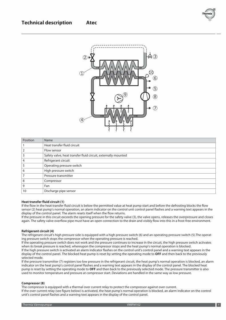
Position Name1 Heat transfer fluid circuit2 Flow sensor3 Safety valve, heat transfer fluid circuit, externally mounted4 Refrigerant circuit5 Operating pressure switch6 High pressure switch7 Pressure transmitter8 Compressor9 Fan10 Discharge pipe sensor
Heat transfer fluid circuit (1)If the flow in the heat transfer fluid circuit is below the permitted value at heat pump start and before the defrosting blocks the flowsensor (2) heat pump's normal operation, an alarm indicator on the control unit control panel flashes and a warning text appears in thedisplay of the control panel. The alarm resets itself when the flow returns. If the pressure in this circuit exceeds the opening pressure for the safety valve (3), the valve opens, releases the overpressure and closesagain. The safety valve overflow pipe must have an open connection to the drain and visibly flow into this in a frost-free environment.
Refrigerant circuit (4)The refrigerant circuit's high pressure side is equipped with a high pressure switch (6) and an operating pressure switch (5).The operat-ing pressure switch stops the compressor when the operating pressure is reached.If the operating pressure switch does not work and the pressure continues to increase in the circuit, the high pressure switch activateswhen its break pressure is reached, whereupon the compressor stops and the heat pump's normal operation is blocked.If the high pressure switch is activated an alarm indicator flashes on the control unit's control panel and a warning text appears in thedisplay of the control panel. The blocked heat pump is reset by setting the operating mode to OFF and then back to the previouslyselected mode.If the pressure transmitter (7) registers too low pressure in the refrigerant circuit, the heat pump's normal operation is blocked, an alarmindicator on the heat pump's control panel flashes and a warning text appears in the display of the control panel. The blocked heatpump is reset by setting the operating mode to OFF and then back to the previously selected mode. The pressure transmitter is alsoused to monitor temperature and pressure at compressor start. Deviations are handled in the same way as low pressure.
Compressor (8)The compressor is equipped with a thermal over current relay to protect the compressor against over current.If the over current relay (see figure below) is activated, the heat pump's normal operation is blocked, an alarm indicator on the controlunit's control panel flashes and a warning text appears in the display of the control panel.
Technical description Atec
Thermia Värmepumpar VMIFM102 9

The blocked heat pump is reset by setting the operating mode to OFF and then back to the previously selected mode.The compressor is also equipped with an internal protector that stops the compressor if it risks becoming overheated. The internal pro-tector cannot be reset manually, the compressor must cool before it can be restarted. No alarm connected to this protector.The discharge pipe sensor (10) stops the compressor at too high pressurised gas temperature. This is indicated in the display by asquare. The stop is ceased when the temperature becomes normal.
Fan (9) The fan motor is equipped with motor protection. If this is activated, the heat pump's normal operation is blocked, an alarm indicator onthe control unit's control panel flashes and a warning text appears in the display of the control panel.Alarms can be caused by objects sticking in the fan or the fan having frozen solid. Rectify the cause of the alarm and reset the heat pumpby setting the operating mode to OFF and then back to the previously selected mode.
Speed (rpm) controlled circulation pumpThe circulation pump has an internal overload protector, which is reset automatically after cooling.The overload protector also activates the alarm for the circulation pump and blocks the heat pump's normal operation. Indication occursby the alarm indicator flashing on the control unit's control panel and a warning text appears in the display of the control panel. Thecirculation pump will attempt to start for 45 seconds every 5 minutes to try to acknowledge the alarm automatically. If the function isnot normal after 5 start attempts the heat pump is constantly blocked and must be reset by setting the operating mode to OFF and thenback to the previously selected mode.
Alarm modeIf an alarm that affects the heat pump's normal operation is activated this will be indicated in the control panel's display window. Inorder to further attract attention, the heat pump will not produce hot water.The heat pump will initially try to meet the heat demand using the compressor. If this is not possible, the built-in electric heating ele-ment engages.
Immersion heaterThe auxiliary heater consists of an electric heating element mounted on the heating system supply line. It has an overheat protector thatswitches off the electric heating element if it is at risk of becoming overheated. The overheat protector's control panel is located in thecontrol unit (see the image below).If the overheat protector is activated an alarm indicator flashes on the heat pump's control panel and a warning text appears.The overheat protector is reset by pushing the reset button, which is on the overheat protector.
Electrical systemThe heat pump control and control unit are fused with fuses F1 and F2 (see figures below).
Technical description Atec
VMIFM102 Thermia Värmepumpar10

44
11
22
33
22
33
22
AA
BB CC DD
Position DescriptionA Heat pumpB Control unit Atec StandardC Control unit Atec PlusD Control unit Atec Total
Position Description1 Fuse F12 Fuse F23 Overheating protection4 Overcurrent protection
Technical description Atec
Thermia Värmepumpar VMIFM102 11

2 Heat pump data, components
2.1 Heat pump data, components
2.1.1 Indoor units
1
Atec Standard
1
2
34
Atec Plus
1
2
43 5
Atec Total
1. Control module (transparent in image)2. Immersion heater3. Reversing valve4. Circulation pump5. Water heater
Technical description Atec
VMIFM102 Thermia Värmepumpar12

2.1.2 Outdoor unit
11
10
12
13
14
16
15
17
1
2
3
4
5
6
7
8
9
19
18
Position Name Position Name1 Electrical cabinet 11 Electronic expansion valve2 Fan 12 Receiver3 Pressure transmitter 13 Drying filter4 Suction line 14 Heat exchanger5 Compressor 15 Flow sensor6 High pressure switch 16 Heating system supply line7 Operating pressure switch 17 Return line heating system8 Four-way valve 18 Solenoid9 Discharge pipe 19 Non-return valve10 Air heat exchanger
Technical description Atec
Thermia Värmepumpar VMIFM102 13
3 Important parameters
3.1 Heat production - calculating
The indoor temperature is adjusted by changing the heat pump’s heat curve, which is the control system’s tool for calculating what thesupply temperature should be for water that is sent out in the heating system. The heat curve calculates the supply temperature de-pending on the outdoor temperature. The lower the outdoor temperature, the higher the supply temperature. In other words, the sup-ply temperature of the water fed to the heating system will increase linearly as the outdoor air temperature falls.
The heat curve will be adjusted in connection with installation. It must be adapted later on, however, to obtain a pleasant indoor tem-perature in any weather conditions. A correctly set heat curve reduces maintenance and saves energy.
3.2 CURVE
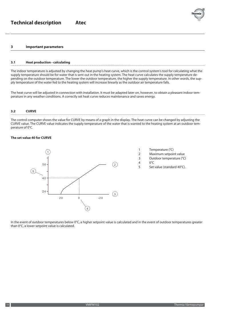
The control computer shows the value for CURVE by means of a graph in the display. The heat curve can be changed by adjusting theCURVE value. The CURVE value indicates the supply temperature of the water that is wanted to the heating system at an outdoor tem-perature of 0°C.
The set value 40 for CURVE
4
20 0 -20
24
40
56 2
3
1
5
1 Temperature (°C)2 Maximum setpoint value3 Outdoor temperature (°C)4 0°C5 Set value (standard 40°C).
In the event of outdoor temperatures below 0°C, a higher setpoint value is calculated and in the event of outdoor temperatures greaterthan 0°C, a lower setpoint value is calculated.
Technical description Atec
VMIFM102 Thermia Värmepumpar14

Increasing or reducing the CURVE changes the slope of the curve
20 0 -20
24
40
56 2
3
11 Temperature (°C)2 Maximum setpoint value3 Outdoor temperature (°C)
If the CURVE value is increased, the heat curve will become steeper and if the value is reduced, it will become flatter.
The most energy efficient and cost effective setting is achieved by changing the CURVE value which leads to fewer starts and longeroperating times. For a temporary increase or reduction, adjust the ROOM value instead.
3.3 ROOM
If you wish to increase or reduce the indoor temperature, change the ROOM value.
Changing the ROOM value
When changing the ROOM value, the angle of the curve on the system's heat curve does not change, instead the entire heat curve ismoved by 3°C for every degree change of the ROOM value. The reason that the curve is adjusted 3°C is that an approximate 3°C increasein supply temperature is usually needed to increase the indoor temperature 1°C.
20 0 -20
24
40
56 2
3
11 Supply temperature (°C)2 Maximum supply temperature3 Outdoor temperature (°C)
Changing the CURVE value
When changing the CURVE value, the angle of the curve on the system's heat curve changes.
Technical description Atec
Thermia Värmepumpar VMIFM102 15

The relationship of the supply temperature to the outdoor temperature will not be affected. The supply temperature will be increased orreduced by the same number of degrees all along the heat curve. I.E. The entire heat curve rises or drops instead of the curve gradientchanging.
This method of adjusting the indoor temperatures can be used for a temporary raise or drop. For long term increases or reductions ofthe indoor temperature, the heat curve should be adjusted.
3.4 Adjusting the heat curve a -5°C, 0°C and 5°C
Sometimes, at outdoor temperatures between -5°C and +5°C, part of the heat curve may need adjusting if the indoor temperature is notconstant. For this reason, the control system includes a function which only adjusts the heat curve at three outdoor temperatures: -5°C,0°C and +5°C.
This function will allow one to increase or reduce the setpoint value for the supply line temperature, without affecting the rest of theheat curve, at three specific outdoor temperatures. If, for example, the outdoor temperature is -5°C, the supply temperature will changegradually between 0°C and -10°C, maximum adjustment being reached at -5°C.The figure below shows the adjusted CURVE -5. The adjustment can be seen in the graph in the form of a bump.Choose to adjust theheat curve individually at three specified outdoor temperatures: -5°C, 0°C and +5°C. The supply temperature can be changed by plus/minus 5°C.
20 0 -20
24
40
56
-52
1
3
Fig. 4: The adjusted curve at -5°C
Position Description1 Supply temperature (°C)2 Outdoor temperature (°C)3 Local higher supply temperature at -5°C
3.5 HEAT STOP
The HEAT STOP function automatically stops all production of radiator heat when the outdoor temperature is equal to, or higher than,the value entered for heat stop.
When the heat stop function is activated, the circulation pump will be turned off - except when hot water is being produced. The circula-tion pump will be "exercised" for one minute per day. The factory set value for activating heat stop is an outdoor temperature of 17°C. Ifthe heat stop function is active, the outdoor temperature must drop 3°C when setting, before the heat stop is de-activated.
3.6 MIN and MAX
The MIN and MAX values are the lowest, respectively highest set point values that are allowed for the supply temperature.
Adjusting the minimum and maximum supply temperatures is particularly important if your home has under floor heating.
Technical description Atec
VMIFM102 Thermia Värmepumpar16
If your house has under floor heating and parquet floors, the supply line temperature must not exceed 45°C. Otherwise the floor mightget damaged. If you have under floor heating and stone tiles, the MIN value should be 22-25°C, even in summer when no heating isrequired. This is to achieve a comfortable floor temperature.
If your house has a basement, the MIN value should be adjusted to a suitable temperature for the basement in summer. A condition formaintaining the heat in the basement in the summer is that all radiators have thermostat valves that switch off the heat in the rest of thehouse. It is extremely important that the heating system and the radiator valves are trimmed correctly. As it is usually the end customersthemselves who have to carry out trimming, remember to inform them how to carry it out correctly. Also remember that the value forHEAT STOP needs adjusting upwards for summer heating.
3.7 TEMPERATURES
The heat pump can display a graph showing the history of the various sensors’ temperatures and you can see how they have changedover 60 measurement points in time. The time interval between the measurement points can be adjusted between one minute and onehour, factory setting is one minute.
History is available for all sensors, but only the set value is shown in the display for the room sensor. The integral value that may appearis the heating system’s energy balance.
3.8 INTEGRAL
The heat demand in the house depends on the season and weather conditions and is not constant. The heat demand can be expressedas temperature difference over time and can be calculated giving an integral value as a result (heat demand). To calculate the integralvalue, the control system uses several parameters.
A heat deficit is needed to start the heat pump, and there are two integral values, A1 (default value = -60), which starts the compressorand A2, (factory set = -600), which starts the auxiliary heater and A3, which starts the external auxiliary heater. During heat production,the deficit reduces and when the heat pump stops, the inertia in the system causes a surplus of heat.
The integral value is a measurement of the area under the time axis and is expressed in degree minutes. The figure below shows thefactory settings for the integral values that the heat pump has. When the integral value has reached the set value for INTEGRAL A1 thecompressor starts. If the integral value does not reduce but continues to increase the internal additional heat will start when the integralvalue reaches the set value for A2 and the external value at set value for A3
Technical description Atec
Thermia Värmepumpar VMIFM102 17

Starting and stopping heat pump operation based on integral values
15
7
3
4
1411
1312
34
6
12
11
88
2
5
2
10
9
1
5
10
9
15 15
16
1 Integral2 Heat surplus3 INTEGRAL A14 INTEGRAL A25 Heating deficit6 Time7 Heat pump operation8 No operation9 Compressor10 Internal additional heater11 Compressor start (A1)12 Auxiliary heater start A213 Aux. heater stop (latest by A1)14 Compressor stop (=0)15 INTEGRAL A316 External auxiliary heater
The calculation of the integral value stops during heat stop. The calculation of the integral value stops when heat stop has stopped.
In this example INTEGRAL A3 < INTEGRAL A2. This means that the external addition will be activated earlier than the internal addition.On the condition that these are activated.
Technical description Atec
VMIFM102 Thermia Värmepumpar18
3.9 HYSTERESIS
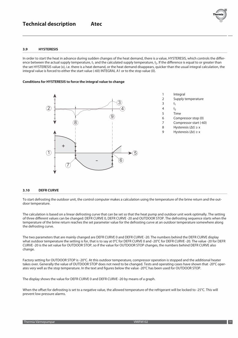
In order to start the heat in advance during sudden changes of the heat demand, there is a value, HYSTERESIS, which controls the differ-ence between the actual supply temperature, t1 and the calculated supply temperature, t2. If the difference is equal to or greater thanthe set HYSTERESIS value (x), i.e. there is a heat demand, or the heat demand disappears, quicker than the usual integral calculation, theintegral value is forced to either the start value (-60) INTEGRAL A1 or to the stop value (0).
Conditions for HYSTERESIS to force the integral value to change
1 5
2
89
34
67
1 Integral2 Supply temperature3 t1
4 t2
5 Time6 Compressor stop (0)7 Compressor start (-60)8 Hysteresis (Δt) ≥ x9 Hysteresis (Δt) ≥ x
3.10 DEFR CURVE
To start defrosting the outdoor unit, the control computer makes a calculation using the temperature of the brine return and the out-door temperature.
The calculation is based on a linear defrosting curve that can be set so that the heat pump and outdoor unit work optimally. The settingof three different values can be changed: DEFR CURVE 0, DEFR CURVE -20 and OUTDOOR STOP. The defrosting sequence starts when thetemperature of the brine return reaches the set parameter value for the defrosting curve at an outdoor temperature somewhere alongthe defrosting curve.
The two parameters that are mainly changed are DEFR CURVE 0 and DEFR CURVE -20. The numbers behind the DEFR CURVE displaywhat outdoor temperature the setting is for, that is to say at 0°C for DEFR CURVE 0 and -20°C for DEFR CURVE -20. The value -20 for DEFRCURVE -20 is the set value for OUTDOOR STOP, so if the value for OUTDOOR STOP changes, the numbers behind DEFR CURVE alsochange.
Factory setting for OUTDOOR STOP is -20°C. At this outdoor temperature, compressor operation is stopped and the additional heatertakes over. Generally the value of OUTDOOR STOP does not need to be changed. Tests and operating cases have shown that -20°C oper-ates very well as the stop temperature. In the text and figures below the value -20°C has been used for OUTDOOR STOP.
The display shows the value for DEFR CURVE 0 and DEFR CURVE -20 by means of a graph.
When the offset for defrosting is set to a negative value, the allowed temperature of the refrigerant will be locked to -25°C. This willprevent low pressure alarms.
Technical description Atec
Thermia Värmepumpar VMIFM102 19

How the value for DEFR CURVE 0 can be set
4
0
-16
-32
-25 -15 -5 5
1
2
3
1 Temperature, input brine line2 Adjustable interval for DEFR CURVE 0 is a brine return between
-5°C and -15°C at 0°C outdoor temperature3 Outdoor temperature4 Set value for DEFR CURVE -20
The value for OUTDOOR STOP corresponds to the fact that the compressor will no longer be used for heating or hot water production ifthe outdoor temperature is the same as or lower than the value. Heating and hot water production will then be produced with the helpof the auxiliary heater.
The value for DEFR CURVE 0 is the temperature that the brine return is permitted to reach when a defrost must start at outdoor tempera-ture 0°C.
In the corresponding way the value for DEFR CURVE -20 is the temperature that the brine return has when a defrost should start at theset outdoor temperature for OUTDOOR STOP. The setting for DEFR CURVE –20 means that the value OUTDOOR STOP (-20°C) is reducedby between 1 and 8 degrees. This also determines how much lower the temperature for the brine return may be than -20°C in this case.
How the value for DEFR CURVE -20 can be set
0
-16
-32
-25 -15 -5 5
1
3
5
4
2
1 Temperature, input brine line2 Set value for DEFR CURVE 03 Outdoor temperature4 Set value for OUTDOOR STOP, -20°C5 Adjustable value for DEFR CURVE -20 is 1°C to 8°C lower than OUT-
DOOR STOP
These three settings together create the defrosting curve and all three values have an effect on when defrosting will start, even if it ismainly DEFR CURVE 0 and DEFR CURVE -20 that is changed.
Technical description Atec
VMIFM102 Thermia Värmepumpar20
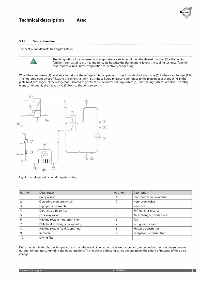
3.11 Defrost function
The heat pump defrosts (see figure below).
NThe designations for condenser and evaporator are switched during the defrost function (like the coolingfunction) compared to the heating function, because the designations follow the cooling technical functionthat respective units have (evaporation respectively condensing).
When the compressor (1) receives a start signal the refrigerant is compressed in gas form via the 4 way valve (5) to the air exchanger (15).The hot refrigerant gives off heat to the air exchanger (15), shifts to liquid phase and continues to the plate heat exchanger (7). In theplate heat exchanger (7) the refrigerant is heated to gas form by the hotter heating system (6). The heating system is cooled. The refrig-erant continues via the 4 way valve (5) back to the compressor (1).
3
2
1
1918
1715
14
16
1113
12
10
9
8
7 6
5
4
Fig. 3: The refrigerant circuit during defrosting
Position Description Position Description1 Compressor 11 Electronic expansion valve2 Operating pressure switch 12 Non-return valve3 High pressure switch 13 Solenoid4 Discharge pipe sensor 14 Refrigerant sensor 25 Four-way valve 15 Air exchanger (condenser)6 Heating system (hot return line) 16 Fan7 Plate heat exchanger (evaporator) 17 Refrigerant sensor 18 Heating system (cold supply line) 18 Pressure transmitter9 Receiver 19 Temperature transmitter10 Drying filter
Defrosting is initiated by low temperature in the refrigerant circuit after the air exchanger and, among other things, is dependent onoutdoor temperature, humidity and operating time. The length of defrosting varies depending on the extent of freezing of the air ex-changer.
Technical description Atec
Thermia Värmepumpar VMIFM102 21
Defrost continues until the air heat exchanger is free of ice and the temperature after the air exchanger has risen to the desired tempera-ture. After completed defrosting the heat pump returns to the operating mode before defrosting.
During defrosting the heat pump retrieves energy from the house's heating system. The water volume in the heating system can beincreased by installing a buffer tank. The buffer tank can also act as a surge tank.
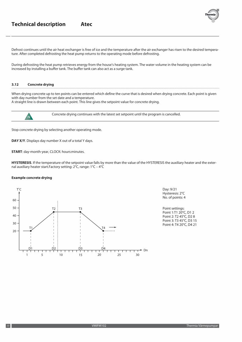
3.12 Concrete drying
When drying concrete up to ten points can be entered which define the curve that is desired when drying concrete. Each point is givenwith day number from the set date and a temperature.A straight line is drawn between each point. This line gives the setpoint value for concrete drying.
NConcrete drying continues with the latest set setpoint until the program is cancelled.
Stop concrete drying by selecting another operating mode.
DAY X/Y. Displays day number X out of a total Y days.
START: day-month-year, CLOCK: hours:minutes.
HYSTERESIS. If the temperature of the setpoint value falls by more than the value of the HYSTERESIS the auxiliary heater and the exter-nal auxiliary heater start.Factory setting: 2°C, range: 1°C – 4°C
Example concrete drying
T˚C
Dn1 5 10 15 20 25 30
20
30
40
50
60
T1 T4
T2 T3
D1 D2 D3 D4
Day: 9/21Hysteresis: 2°CNo. of points: 4
Point settings:Point 1:T1 20°C, D1 2Point 2: T2 45°C, D2 8Point 3: T3 45°C, D3 15Point 4: T4 20°C, D4 21
Technical description Atec
VMIFM102 Thermia Värmepumpar22
T˚C
Dn1 5 10 15 20 25 30
20
30
40
50
60
T1
T4
T2
T3
D1 D2 D3 D4D5 D6D7D8
T5
T6 T7
T8
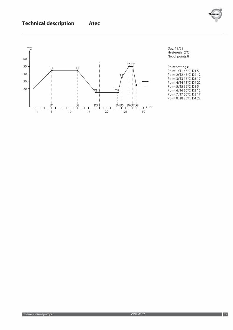
Day: 18/28Hysteresis: 2°CNo. of points:8
Point settings:Point 1: T1 45°C, D1 5Point 2: T2 45°C, D2 12Point 3: T3 15°C, D3 17Point 4: T4 15°C, D4 22Point 5: T5 35°C, D1 5Point 6: T6 50°C, D2 12Point 7: T7 50°C, D3 17Point 8: T8 25°C, D4 22
Technical description Atec
Thermia Värmepumpar VMIFM102 23
4 Technical data
4.1 Atec
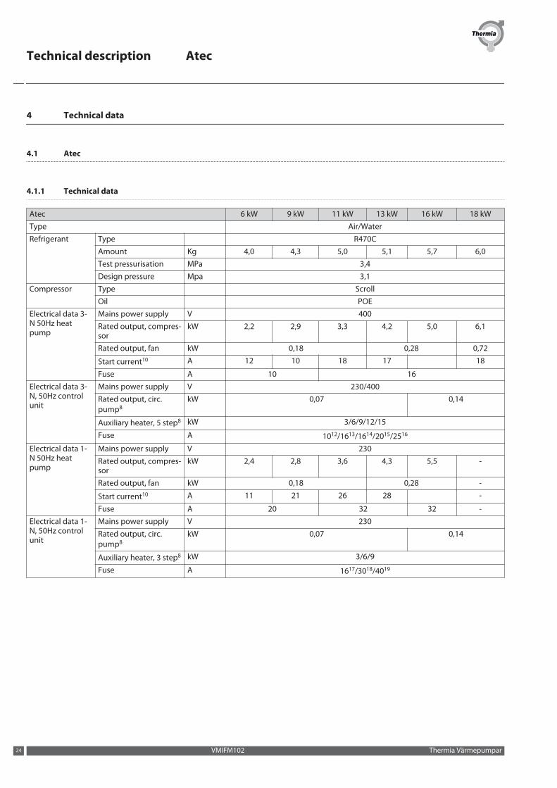
4.1.1 Technical data
Atec 6 kW 9 kW 11 kW 13 kW 16 kW 18 kWType Air/WaterRefrigerant Type R470C
Amount Kg 4,0 4,3 5,0 5,1 5,7 6,0Test pressurisation MPa 3,4Design pressure Mpa 3,1
Compressor Type ScrollOil POE
Electrical data 3-N 50Hz heatpump
Mains power supply V 400Rated output, compres-sor
kW 2,2 2,9 3,3 4,2 5,0 6,1
Rated output, fan kW 0,18 0,28 0,72
Start current10 A 12 10 18 17 18
Fuse A 10 16Electrical data 3-N, 50Hz controlunit
Mains power supply V 230/400Rated output, circ.pump8
kW 0,07 0,14
Auxiliary heater, 5 step8 kW 3/6/9/12/15
Fuse A 1012/1613/1614/2015/2516
Electrical data 1-N 50Hz heatpump
Mains power supply V 230Rated output, compres-sor
kW 2,4 2,8 3,6 4,3 5,5 -
Rated output, fan kW 0,18 0,28 -
Start current10 A 11 21 26 28 -
Fuse A 20 32 32 -Electrical data 1-N, 50Hz controlunit
Mains power supply V 230Rated output, circ.pump8
kW 0,07 0,14
Auxiliary heater, 3 step8 kW 3/6/9
Fuse A 1617/3018/4019
Technical description Atec
VMIFM102 Thermia Värmepumpar24

Atec 6 kW 9 kW 11 kW 13 kW 16 kW 18 kW
Performance11 COP1 3,26 3,40 3,44 3,38 3,21 3,10
Heat factor1 kW 4,73 6,22 7,68 9,10 11,40 13,26
Incoming power1 kW 1,45 1,83 2,23 2,69 3,56 4,28
COP2 4,32 4,38 4,68 4,35 4,12 3,97
Heat factor2 kW 6,49 8,59 11,07 12,30 15,21 17,59
Incoming power2 kW 1,50 1,96 2,36 2,83 3,69 4,42
COP3 4,73 4,73 5,01 4,67 4,61 4,25
Heat factor3 kW 6,87 8,81 10,91 12,64 15,88 18,58
Incoming power3 kW 1,45 1,86 2,18 2,70 3,44 4,37
EER4 2,23 2,35 2,55 2,41 2,29 2,33
Cooling output4 kW 4,21 5,85 7,52 8,85 10,39 13,16
Incoming power4 kW 1,88 2,49 2,95 3,67 4,53 5,65
Nominal flow5 Heating circuit l/s 0,165 0,215 0,263 0,308 0,372 0,430
External availablepressure9
Heating circuit kPa 60,7 59,8 58,7 56,7 96,8 95,9
Pressureswitches /pres-sure transmitter
Low pressure(pressure transmitter)
MPa 0,05
Operation MPa 2,85High pressure MPa 3,1
Water volume Water heater6 l 180
Condenser l 1,6 2,1 2,7 2,7 3,2 4,3
Min water volume in heating system. 22
Atec Standard and Atec Plusl 120 180 220 260 320 360
Min water volume in heating system.22
Atec Totall 60 90 110 130 160 180
Number of units 2Heat pump Dimensions L x W x H mm 856x510x1272 1016x564x1477 1166x570x1557
Weight (empty) kg 125 131 150 155 185 191Noise output level:normal operation7
dB(A) 61,5 61,0 61,0 62,5 67,0 74,5
Noise output level:silent operation7
dB(A) 60,0 59,0 59,5 61,0 64,9 70,5
Fan speed min/max rpm 500/745 500/745 425/620 465/690 625/805 770/1000Control unit AtecStandard
Dimensions L x W x H mm 380x204x600Weight kg 18
Control unit AtecPlus
Dimensions L x W x H mm 420x255x67520
Weight kg 21Control unit AtecTotal
Dimensions L x W x H mm 596x690x184521
Weight (empty) kg 106Weight (filled) kg 286
Measurements are carried out on a limited number of circulation pumps, which can give variations in results. Tolerances in the measurement methods can also give variations.
1) At A2/W35 in accordance with EN14511 (incl. circulation pump, fan and defrosting for Atec Plus and Atec Total).
2) At A7/W35 in accordance with EN14511 (incl. circulation pump and fan for Atec Plus and Atec Total).
3) At A7/W35 Δ10K hot side in accordance with EN 255.
4) At A7/W35 according to EN 14511.
5) Nominal flow: heating circuit Δ10K.
6) Only applies to Atec Total.
7) Sound power level measured according to EN ISO 3741 at A7W35 and frost-free evaporator.
8) Only applies to Atec Plus and Atec Total.
Technical description Atec
Thermia Värmepumpar VMIFM102 25
9) The pressure that must not be exceeded outside the heat pump without falling below the nominal flow.
10) According to IEC61000.
11) The values apply to new heat pumps with clean heat exchangers.
12) Heat pump with 3 kW additional heater.
13) Heat pump with 6 kW additional heater.
14) Heat pump with 9 kW additional heater.
15) Heat pump with 12 kW additional heater.
16) Heat pump with 15 kW additional heater.
17) Heat pump with 3 kW additional heater.
18) Heat pump with 6 kW additional heater.
19) Heat pump with 9 kW additional heater.
20) Including pipe connection
21) Including pipe connection and ± 10 mm for foot adjustment
22) Water volume without hot water heater
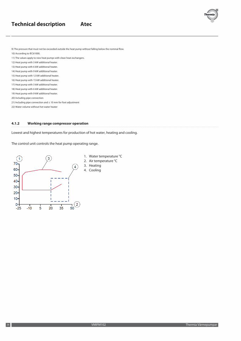
4.1.2 Working range compressor operation
Lowest and highest temperatures for production of hot water, heating and cooling.
The control unit controls the heat pump operating range.
1. Water temperature °C2. Air temperature °C3. Heating4. Cooling
Technical description Atec
VMIFM102 Thermia Värmepumpar26

Technical description Atec
Thermia Värmepumpar VMIFM102 27

Technical description Atec
Thermia Heat PumpsBox 950671 29 ARVIKAPhone +46 570 81300E-mail: [email protected]: www.thermia.com
Danfoss can accept no responsibility for possible errors in catalogues, brochures and other printed material. Danfoss reserves the right to alter its products without notice. This also applies to productsalready on order provided that such alterations can be made without subsequential changes being necessary in specifications already agreed. All trademarks in this material are property of the respectivecompanies. Thermia Värmepumpar and the Thermia Värmepumpar logotype are trademarks of Danfoss A/S. All rights reserved.
VMIFM102 Produced by Thermia Värmepumpar © 2013


