240


TECHNICAL DOCUMENTATION
2A56_PRIME_90020-H-EN
Table of contents
Description ........................................................................................................................... 4Front Face ....................................................................................................................................... 4Rear Face ........................................................................................................................................ 7Panel Mounting ................................................................................................................................. 8UL Requirements ............................................................................................................................. 10
Usage ......................................................................................................................................... 12Password ....................................................................................................................................... 12LCD ............................................................................................................................................... 13Wiring ............................................................................................................................................ 15Digital Inputs .................................................................................................................................. 22Digital Outputs ................................................................................................................................ 24Analog Inputs ................................................................................................................................. 25Hysteresis DI .................................................................................................................................. 29Hysteresis AI .................................................................................................................................. 30
Settings .................................................................................................................................. 31Engine ........................................................................................................................................... 31Speed/Voltage Control ..................................................................................................................... 35Circuit Breakers .............................................................................................................................. 38Synchronization .............................................................................................................................. 42Load/Unload Ramp .......................................................................................................................... 46Regulation KW/KVAR ....................................................................................................................... 47Protections ..................................................................................................................................... 49Control Loop PID ............................................................................................................................. 52
Advanced Settings ..................................................................................................... 53Droop ............................................................................................................................................ 53Load Dependent Start/Stop .............................................................................................................. 54Static Paralleling ............................................................................................................................. 57Load Shedding ................................................................................................................................ 59Maintenance Schedule ..................................................................................................................... 61
Power Plant Application .................................................................................... 62Load Sharing .................................................................................................................................. 62
Advanced Functions .................................................................................................. 65Modbus TCP Mapping ...................................................................................................................... 65Logger ........................................................................................................................................... 66
Communications ............................................................................................................. 67Network ......................................................................................................................................... 67Modbus TCP/IP ............................................................................................................................... 69CRE-Link® ..................................................................................................................................... 72CANopen ........................................................................................................................................ 73SAE J1939 ...................................................................................................................................... 74CAN bus Good Practices ................................................................................................................... 81
Website .................................................................................................................................. 83Access ........................................................................................................................................... 83File Transfer ................................................................................................................................... 84Firmware Update ............................................................................................................................ 86
Appendices .......................................................................................................................... 87ECU J1939 ...................................................................................................................................... 87

TECHNICAL DOCUMENTATION
3A56_PRIME_90020-H-EN
Short Circuit Protection .................................................................................................................... 97Troubleshooting ............................................................................................................................ 105Standards for Generator ................................................................................................................ 109Certifications ................................................................................................................................. 110Software Variables ........................................................................................................................ 113

TECHNICAL DOCUMENTATION
4A56_PRIME_90020-H-EN
Description
Front Face
GENSYS COMPACT PRIME
PIN Buttons Functions
1 SHIFT button Additional functions.
2 RIGHT button Navigation button (Right).
3 DOWN button Navigation button (Down).
4 LEFT button Navigation button (Left).
5 UP button Navigation button (Up).
6 ENTER button Validating entry / MENU.
7 ESC button Cancel entry / escape MENU.
8 INFO button Allows direct access to the current Fault or Alarm display.
9(1) Generator circuit breakerbutton
Can only be used in MAN mode.Generator circuit breaker control. Press to Open. Press to Close (synchronization & load transfer will bedone automatically if Bus is powered & configuration is setup forparalleling operation).
10(1) Mains circuit breaker button
Can only be used in MAN mode.Mains circuit breaker control. Press to Open. Press to Close (synchronization & load transfer will bedone automatically if Bus is powered & configuration is setup for

TECHNICAL DOCUMENTATION
5A56_PRIME_90020-H-EN
PIN Buttons Functions
paralleling operation).
11(1) STOP button
Can only be used in MAN mode.Stop the Generator. Pressing once this button will set the Generator offload and initiate coolingdown sequence.
12(1) START buttonCan only be used in MAN mode.Start the Generator.
13(1) MAN buttonMAN mode. The associated LED lights up when the mode is activated.
14(1) TEST buttonTEST mode.The associated LED lights up if the mode is activated.
15(1) AUTO buttonAUTO mode. The associated LED lights up when the mode is activated.
16 ALARM indicatorThe LED flashes when an alarm appears.
The LED is lit when an alarm is acknowledged, but not reseted.
17 DEFAULT indicatorThe LED flashes when a Fault occurs.
The LED is lit when a Fault is acknowledged, but not reseted.
18 LCD displayScreen size: 40mm x 70mm; Back-light : typical 50cd/m2, configurable.Type: STN; 64 x 128 pixels.
(1) Not availab le according to controller type.Note: Pressing the button STOP twice will set the Generator offload and stop the engine without cooling downsequence.
Navigation keys
Keys Navigation m ode Edition m ode
Scrolling menus.
Modifying parameters values once selected: Whenup/down keys are used to modify values, holding thekey will accelerate the entry scrolling.
Navigating right/left in display. NA
+ will increase/decrease the
brightness of the LCD display.
+ will increase/decrease thecontrast of the LCD display.
In MAN mode, when the Generator is offload, use
to increase/decrease:
§ The speed when the "Speed governor control"page is displayed.§ The voltage when the "AVR control" page is
displayed.
Note: Not availab le on MASTER COMPACT,MASTER COMPACT 1B and BTB COMPACT.
Return to previous menu. Cancel setting and return to Navigation mode.
Accessing a menu / Switching to Edition mode.Validation of the modified parameter and return toNavigation mode.

TECHNICAL DOCUMENTATION
6A56_PRIME_90020-H-EN
Button inhibition
To inhibit front panel buttons, use the i4Gen Suite Software/System/Button inhibition page. This pageshows the list of front panel buttons, tick the corresponding box to inhibit actions on the button.
Table below shows the 16 bits variable used for remote button inhibition by Modbus, each bit is assigned to abutton:
Variable Label Description
[3557] Inhibit key Each 1-bit inhibits a front panel button.
Relation button / inhibition bit [3557]
External button requests
It is possible to remotely activate button actions by Modbus TCP, for a remote manual control for example.If a button action is controlled by Modbus TCP, the last request received (external or from the front panel) istreated in priority and cancel the previous request.MAN / AUTO: If the 2 modes are requested, the MAN mode request cancels the AUTO mode one.
The buttons on the front panel can be replaced by external commands via digital inputs. Modbus TCP/IPModbus mapping
TECHNICAL DOCUMENTATION
7A56_PRIME_90020-H-EN
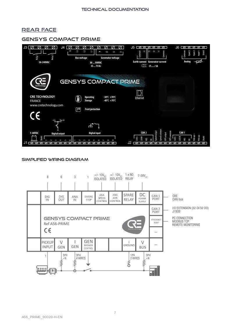
Rear Face
GENSYS COMPACT PRIME
Simplified Wiring Diagram

TECHNICAL DOCUMENTATION
8A56_PRIME_90020-H-EN
Panel MountingThe unit is designed for panel mounting, which provides user with access only to the front panel.
WARNINGTHE UNIT IS NOT GROUNDED· Take all measures against Electronic Static Discharges.
· Do not try to open the unit.Failure to follow these instructions may damage the unit.
Environmental requirements:
· Operating temperature: -20…70°C (-4...158°F); LCD display slows down a bit under -5°C (23°F). Avoid directexposure to the sun.
· Storage temperature: -40...70°C (-40...158°F).
· Altitude: ≤ 4000m (13123ft) for a max AC voltage of 480VAC; ≤ 5000m (16404ft) for a max AC voltage of400VAC.
Unpacking
Make sure the packaging contains:
· The unit.
· 6 connectors.
· 1 fixing kit composed of 2 parts.
· 4 screws.
· A delivery bill.
Unpack and keep the packaging in case of return.Make sure the unit does not show scratches or visible defaults. Otherwise describe them on the RMA sheet(available onCRE TECHNOLOGY website) and return it with the product to your distributors.

TECHNICAL DOCUMENTATION
9A56_PRIME_90020-H-EN
Installation
Preparation
· Torque of mounting brackets: 0.4Nm.
· Cut out the panel to 220x160mm (8.7x6.3in) minimum.
· Make sure the cut-out is smooth and clean.
Mounting
0 Tool : cross-heas screwdriver size 1
1 Pass the unit through the mountingsurface
2 In the rear, cover each of the fourspacers using the 2 parts of the fixingkit.
3 Screw a first corner against the mountingsurface
4 Repeat on the diagonally oppositespacer
5 Repeat on the other diagonal and tightenequally (do not overtighten)

TECHNICAL DOCUMENTATION
10A56_PRIME_90020-H-EN
UL Requirements
Circuit separation
The communication, sensor, and/or battery derived circuit conductors shall be separated and secured tomaintain at least 1/4” (6mm) separation from the Generator and the Bus connected circuit conductors unless allconductors are rated 600V or greater.
Other circuits ratings
For information on circuits ratings, see chapter Wiring.
Mains Ratings
Over-voltage Category III, 300VAC system voltage.
Sensing Generator / Bus Voltage Measurement (J4)300VAC max P-N, 2 phases; 500VAC P-P 3 phases, 35...75Hz.
Current Inputs (J5)Must be connected through listed or recognized isolating current transformers with secondary rating of 5A max50/60Hz. (XODW2.8) Instrument transformers (according to IEEE C57.13 series or the equivalent).
Communication CircuitsMust be connected to communication circuits of UL Listed equipment.
Output Pilot Duty (J3)250VAC, 5A max general purpose, 240VAC, 1/4HP for NO contact, 1/6HP for NC contact Pilot duty: C150,C300.
Digital outputs (J1)FET: Fuel shutoff: 63VA, 1.8A max current.
Overcurrent protection (DC supply and L1, L2, L3, N)
Installer shall protect DC supply and L1, L2, L3, N by fuse Type: R/C (JDYX2/7), or R/C (JDYX2) and CSACertified Class 1422-30.Rating of fuses:
· DC supply to be protected by 5A, 40VDC max.
· L1, L2, L3, N, fuse protection 100mA/600VAC max.
Terminals Wiring
Terminal (screw type):
· Tightening Torque: 3.5lb.in (0.4Nm).
Wires :
· 28-14 AWG, Cu, 75°C min. Conductor protection must be provided in accordance with NFPA 70, Article 240.Low voltage circuits (35VDC or less) must be supplied from the engine starting battery or an isolated secondarycircuit.
Environment
Device must be installed in an unventilated or filtered ventilation enclosure to maintain a pollution degree 2environment.

TECHNICAL DOCUMENTATION
11A56_PRIME_90020-H-EN
Maximum surrounding air temperature rating: 45°C.
ADVANCED WIRING DIAGRAM
Wiring diagrams available on the website CRE TECHNOLOGY : GENSYS COMPACT PRIME HMI _ CORE -Standard wiring schematics
Installation
For information on installing the product, see chapter Panel Mounting.

TECHNICAL DOCUMENTATION
12A56_PRIME_90020-H-EN
Usage
Password
ADVICEUSEFUL INFORMATION
§ Adjustment tip
§ Using the module
Failure to comply with these recommendations may cause the module to malfunction.
The menus will be automatically locked if no operation is performed during the time set in theSystem menu (Factory setting: 30 minutes).The standby screen will be displayed.
The module provides secured password access to protect configuration changes and limit data accessibility:
Level Default password AuthorizationAccessible pages and
items
0 No password. Press
By default, this level isnot password protected,but you can implementone.
Display menu pagesonly.
1 1User level, settings andcommissioning.
Display, Configurationand System menuspages.
2 1234Used to changeadvanced settings.
Advanced settings( i4Gen Suite Softwareonly).
Passwords can be changed via CRE PC software: i4Gen Suite Software
To access the Display menu, press .
To access the Configuration and System menus, the padlock must be released:
1. Press to select Configuration or System.
2. Press to switch to password input mode (as for other settings).
3. Change the character by pressing
4. Move to the next character by pressing
5. Repeat the operation for each character.
6. Confirm the password by pressing

TECHNICAL DOCUMENTATION
13A56_PRIME_90020-H-EN
LCD
Navigation
Press , then, select the required menu, then press and enter the level 1 password if
necessary (Configuration & System):
A black pointer spots the currently selected item/setting.Three main menus are available on the LCD screen and in i4Gen Suite Software:
· Display gives all product measurements in real time.
· Configuration is used to adjust the settings done with i4Gen Suite Software/Configuration.
· System is used to adjust the system settings (Date/Hour, screen features, ...) done with i4GenSuite Software/System.
To cycle through the menus and menu items, press or
To cycle through the pages of lists of settings, press or
Edition
To change a setting:1. Navigate to the setting.
2. Press to switch to Edition mode; the current value blinks.
3. Press or to get the new value.
4. Press to validate the new value, to reject it. Module returns to Navigation mode.
It is also possible to change settings using Modbus TCP.
Dedicated pages
Dedicated pages include:
· Fault : Active fault and archive pages.
· Alarm : Active alarm and archive pages.
· Information pages.
At any time, faults/alarms/information can be displayed on the LCD screen by pressing the button .
If a fault is active and has not been acknowledged yet, the active fault page will be displayed.Otherwise, if an alarm is active and has not yet been acknowledged, the active alarms page will be displayed.Otherwise the information page will appear.
It is then possible to navigate through these dedicated pages using the arrow buttons.
To return to the previous page, press or .

TECHNICAL DOCUMENTATION
14A56_PRIME_90020-H-EN
EVENTS
Up to 15 active events and 30 archived events can be displayed on the screen.
Each event is time-stamped as follows:jj/mm/yy hh:mn:ss protec. label On (or Off).
To reset events, press +
Note: Correct the condition that triggered the protection before performing a reset; if necessary, the protectionwill trip again.
Information
These pages allow to display the power and engine current state with the associate elapsed time in this state.Power [4000] displays the unit current state regarding power management.Engine [4001] displays the unit current state regarding the engine.Information variables: to display any variable, enter the code of the variable to be displayed.
TECHNICAL DOCUMENTATION
15A56_PRIME_90020-H-EN
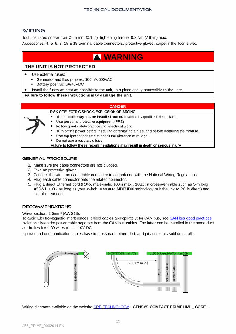
WiringTool: insulated screwdriver Ø2.5 mm (0.1 in), tightening torque: 0.8 Nm (7 lb-in) max.
Accessories: 4, 5, 6, 8, 15 & 18-terminal cable connectors, protective gloves, carpet if the floor is wet.
WARNINGTHE UNIT IS NOT PROTECTED
· Use external fuses:§ Generator and Bus phases: 100mA/600VAC§ Battery positive: 5A/40VDC
· Install the fuses as near as possible to the unit, in a place easily accessible to the user. Failure to follow these instructions may damage the unit.
DANGERRISK OF ELECTRIC SHOCK, EXPLOSION OR ARCING
§ The module may only be installed and maintained by qualified electricians.§ Use personal protective equipment (PPE)§ Follow good safety practices for electrical work.§ Turn off the power before installing or replacing a fuse, and before installing the module.§ Use equipment adapted to check the absence of voltage.§ Do not use a resettable fuse.Failure to follow these recommendations may result in death or serious injury.
General procedure
1. Make sure the cable connectors are not plugged.2. Take on protective gloves.3. Connect the wires on each cable connector in accordance with the National Wiring Regulations.4. Plug each cable connector onto the related connector.5. Plug a direct Ethernet cord (RJ45, male-male, 100m max., 100W; a crossover cable such as 3-m long
A53W1 is OK as long as your switch uses auto MDI/MDIX technology or if the link to PC is direct) andlock the rear door.
Recommendations
Wires section: 2.5mm² (AWG13).To avoid ElectroMagnetic Interferences, shield cables appropriately; for CAN bus, see CAN bus good practices.Isolation : keep the power cable separate from the CAN bus cables. The latter can be installed in the same ductas the low level I/O wires (under 10V DC).
If power and communication cables have to cross each other, do it at right angles to avoid crosstalk:
Wiring diagrams available on the website CRE TECHNOLOGY : GENSYS COMPACT PRIME HMI _ CORE -

TECHNICAL DOCUMENTATION
16A56_PRIME_90020-H-EN
Standard wiring schematics

TECHNICAL DOCUMENTATION
17A56_PRIME_90020-H-EN
Upper blocks
DANGEREXPOSED TERMINALSDo not touch L1, L2, L3 terminals nor use non-insulated tools near them. These terminals areunprotected and will expose the user to dangerous voltages.Failure to follow this instruction may result in death, serious injury or equipmentdamage.
Block and mark Description Note
Breaker commandsNormally open. Breaking capacity: 5A,240VAC.
Relay 1 Relay 1 +
Relay 1 –
Relay 2 Relay 2 +
Relay 2 –
AC voltage (1) 100...480VAC, 35…75Hz, 100mA max;accuracy: 1% fsd.
N Generator N Optional.
L3 Generator L3
These lines must be protected externallywith 100mA/600VAC fuses.
L2 Generator L2
L1 Generator L1
N Bus N Optional.
L3 Bus 3
These lines must be protected externallywith 100mA/600VAC fuses.
L2 Bus 2
L1 Bus 1
Current inputs(1) Short-circuit protection available.
Bus common GND Connect to the ground.
Bus current I1 Bus I1
0…5A. Maximum rating: 15A during 10s.
· Burden: 1VA. Keep the lead lengthshort to preserve accuracy (up to0.5% full scale deviation).
· The maximum of the external CT ratiois 3250 (i.e. 3250:1 or, preferably,16250:5).
· On GENSYS COMPACT PRIME, thisinput must be used only for the earthfault protection.
· On GENSYS COMPACT MAINS andAMF COMPACT, if Mains powermeasurement is configured as "mA"or "Unused", this input can be usedas an earth current measurement.

TECHNICAL DOCUMENTATION
18A56_PRIME_90020-H-EN
Block and mark Description Note
Generator current I3 Generator I3 0…5A. Maximum rating: 15A during 10s.
· Burden: 1VA. Keep the lead lengthshort to preserve accuracy (up to0.5% full scale deviation).
· The maximum of the external CT ratiois 3250 (i.e. 3250:1 or, preferably,16250:5).
Generator current I2 Generator I2
Generator current I1 Generator I1
Generator common GNDOptionally connected to CT –. For a 2-CTsetup, see further.
Analog inputs 0...500W.
Common Connect it to battery -.
Input 3 Available input
Input 2 Available input
Input 1 Available input
Shield GND Ground plane.
(1) Not availab le according to controller type.

TECHNICAL DOCUMENTATION
19A56_PRIME_90020-H-EN
Lower blocks
WARNINGRISK OF EQUIPMENT DAMAGE· Connect battery negative to the module terminal 8...35VDC– with 2.5mm² (AWG13) cable.Failure to follow this instruction can damage the controller.
Block and mark Description Notes
7...38VDC
- Power supply - 2.5mm² (AWG13).
+ Power supply +7…38VDC, consumed current: 130mA at 24V (standbyand operation).
Shield GND Connect to the ground.
Digital outputs
Free digital output (max: 1.8A). Protected against shortcircuits. A reactive load is supported. Not isolated frompower supply.
1
Available outputs
2
3
4
5
6
Digital inputs
Free digital input with 10kΩ pull-up. Accepts NO or NCcontact to 0V. Not isolated from power supply.
1
Available inputs
2
3
4
5
6
7
8
9
CAN2: J1939-Extensions Isolated CAN bus J1939/CANopen. Twisted pair.
CAN L Blue wire.
CAN H White wire.

TECHNICAL DOCUMENTATION
20A56_PRIME_90020-H-EN
Block and mark Description Notes
Resistor -Strap to CAN H when inner resistor must be inserted (busends).
Shield 0V Connect the cable shield herein.
Speed (1) Compatible with all analog speed controllers. Isolatedfrom power supply.
Out Speed output + Analog output ±10V to speed controller.
common Speed output -Twisted pair; length. < 5m (16ft) if unshielded, < 50m maxif shielded.
AVR (1) Compatible with most voltage regulators. Isolated frompower supply.
Out AVR output + Analog output ±10V to voltage regulator.
Common AVR output –Twisted pair; length. < 5m (16ft) if unshielded, < 50m maxif shielded.
CAN1 : CRE-Link® (1) Isolated CAN© bus, use twisted pair.
CAN LWhite wire with blue strip (when using a CRETECHNOLOGY cable).
CAN HBlue wire with white strip (when using a CRETECHNOLOGY cable).
Resistor -Strap to CAN H when inner resistor must be inserted (busends).
Shield 0V Connect the cable shield herein.
Pickup (1) 100Hz...10kHz. Voltage limits between + /–2...40VAC.Speed measurement for speed regulation, crankmanagement and over-speed. Better option than alternator voltage.An over-speed shutdown device independent of themodule is required.The alarm can be generated by ECU or by the module.
Pickup +
Pickup –
(1) Not availab le according to controller type.
WARNINGRISK OF EQUIPMENT DAMAGESwitch off the unit before plugging or unplugging the CAN bus connector or disconnecting wires.Failure to follow this instruction can damage the CAN transmitter/receiver.
Note: On loss of power supply, the unit survives for 70ms at 24V, and 20ms at 12V.
Connection diagrams
These diagrams show that the PT (Potential Transformers) can be connected in various ways.· Star (wye) on Generator side (1 insulated high-voltage terminal per PT); the ratio is for example:
· See on Bus side (2 insulated high-voltage terminals per PT); the ratio is for example:
Other systems of voltage
For bi-phase 180° application, connect voltages and currents to L1-L3 terminals (and N). The same logicapplies for I1-I3 (and common).If mono-phase is selected, connect voltages and currents to the terminals L1-N. The same logic applies for I1

TECHNICAL DOCUMENTATION
21A56_PRIME_90020-H-EN
and common.
Powering the module with a 12VDC battery
A voltage drop from 12V to 6V can occur when the power consumption of the starter is too high and the batteryundersized. This drop can reset the Module each time it gets powered. To counter this problem, a capacitor anda diode need to be wired as indicated in the schematic bellow:
The diode needs to be able to handle high currents (ex: Littelfuse DST2045AX). The value of the capacitor hasto be around 24000 µF (ex : KEMET capacitors).
D+ wiring
The D+ line of the alternator needs to be wired as shown below to ensure the magnetization of the field coil:

TECHNICAL DOCUMENTATION
22A56_PRIME_90020-H-EN
Digital InputsSeveral parameters can be configured from the i4Gen Suite Software:
· Label
· Validity
· Direction
· T ON
· T OFF
· Function
Label
This is the name you give to the input. The name will be shown in the digital inputs, information, alarm, and faultscreens if programmed accordingly.
Validity
Validity indicates when the digital input is taken into account. It can take four values:
Value Validity Description
0 Never Never active: must be selected if you do not use the input.
1 Always Always active: input is monitored as long as the module is powered.
2 Post-start Input is monitored by the end of the "Safety on delay” [2004]. (1)
3 Stabilized Input is monitored when the Generator is ready for use.
(1) Configure the protection inhib ition time in i4Gen Suite Software/Configuration/Time-outs and Delays.
Direction
For each input, two options are available:
Value Label Function
0 Normally open To be used for standard cases unless the input is used as protection
1 Normally closed Must be selected if the input is normally connected to 0V (open when active)

TECHNICAL DOCUMENTATION
23A56_PRIME_90020-H-EN
Delays
For each input, two delays can be defined in 100ms steps between 0 and 6553s:
Functions
Each input can be configured. To access all functions, use i4Gen Suite Software.Function list is available in Software variables.

TECHNICAL DOCUMENTATION
24A56_PRIME_90020-H-EN
Digital OutputsSeveral parameters can be configured from the i4Gen Suite Software:
· Direction
· Function
· Pulse length: 0 means no pulse
Direction
Each output can be:· NE: normally energized; the output is de-energized when its function is activated.
· ND: normally de-energized; the output is energized when its function is activated.
Pulse LENGTH
Each digital output can be configured to act as a pulse. The pulses lengths are defined with the parameters[2761] to [2766].Set to 0 in order to have a continuous output (no pulse).
Functions
Each output can be configured. To access all functions, use i4Gen Suite Software.Function list is available in Software variables.

TECHNICAL DOCUMENTATION
25A56_PRIME_90020-H-EN
Analog InputsIn addition to the speed and electrical currents and voltages, three analog inputs are available. They measure aresistance 0…500Ω . However, they can serve as digital inputs or 20 mA transducer input.
Input
Each input is tagged with a name and preset to a function. It features several attributes preset in i4Gen SuiteSoftware/Configuration/Inputs/Analog inputs:
· Function
· Unit: No unit, V, KV, mA, A, KA, Hz, KW, KWh, KVAR, KVARh, rpm, %, Bar, mbar, KPa, psi, °, °C,°F, L, Gal, s, h, days, Hz/s, m3/h, L/h, Gal/h.
· Calibration: Measure value according to resistor value in Ω.
Calibration
Calibration is used to estimate a reading from a resistance value by interpolation between 2 wrapping resistancevalues. Negative values are supported for readings.Enter a table in i4Gen Suite Software / Configuration / Inputs / Analog inputs.Enter the limits of reading according to the sensor calibration.Calculate and enter the intermediary readings to get a linear distribution.Reference table for oil pressure:
Ω VDO 5b VDO 10b VDO 25b AC 10b Veglia 8b Veglia 12b Dat 10b
0 -0.3 -0.4 -2.1 -0.2 8.4 12.6 12.1
50 1.1 2.1 5.2 5.4 6.5 9.8 8.2
100 2.6 5.1 12.6 11.1 4.6 6.9 4.8
150 4.0 8.3 19.9 16.9 2.7 4.1 1.8
200 5.5 12.2 27.3 20.0 0.8 1.2 -0.5
250 7.0 20.0 30.0 20.0 -0.5 -0.7 0
300 8.5 20.0 30.0 20.0 0 0 0
350 9.9 20.0 30.0 20.0 0 0 0
400 11.4 20.0 30.0 20.0 0 0 0
450 12.9 20.0 30.0 20.0 0 0 0
500 14.3 20.0 30.0 20.0 0 0 0
Reference table for water temperature:
Ω VDO 120° VDO 150° Veglia Datcon L Datcon H AC
0 145 1000 1000 1000 0 1000
50 90 112 134 97 50 97
100 68 87 111 70 100 70
150 57 72 98 54 150 54
200 49 62 89 43 200 43
250 43 54 81 34 250 34
300 38 48 76 28 300 28
350 34 43 71 22 350 22
400 32 38 67 17 400 17
450 29 33 63 12 450 12
500 27 28 59 7 500 7

TECHNICAL DOCUMENTATION
26A56_PRIME_90020-H-EN
Protections
Several parameters can be configured from the i4Gen SuiteSoftware/Configuration/Protections/Engine/battery protections/Analog inputs protection:
· Level (LV): limit value in units; it can be a low or high threshold.
· Delay (TM): time after which the protection is triggered.
· Validation (CT): protection type to which the signal contributes (8 potential values).
· Direction (SS): threshold polarity (0 = low, 1 = high).
Note: Do not confuse Validation with Validity (engine state that validates a digital input).
Summary
The attributes are shown in i4Gen Suite Software:
Protections
Threshold Timer Control Direction Function
AI 1 level 1 2600 2601 26022606 2607
AI 1 level 2 2603 2604 2605
AI 2 level 1 2608 2609 26102614 2615
AI 2 level 2 2611 2612 2613
AI 3 level 1 2616 2617 26182622 2623
AI 3 level 2 2619 2620 2621
Use of an analog input as a digital input
To mimic a digital input, connect the input to Power– through a switch, and select the function to implement inthe list i4Gen Suite Software/Configuration/Inputs/Analog inputs/Function.Then set the delay, validity and polarity.
Use of an analog input as a transceiver input
To act as a 0...20mA input or 4...20mA, connect the input with a 39Ω resistor between the analog input and theanalog common, and select the function 20mA in the list i4Gen Suite Software / Configuration/Inputs /Analog inputs / Function. The calibration of the 20mA transducer can then be performed as on a resistive analog input depending on thecharacteristics of the sensor.
How to connect analog or digital sensors
You can use 1 or 2-wire analog sensors, or 1-wire or 2-wire logical sensors. CRE RECOMMANDATION: In each case you must always connect the "common" J6 to the "- Power Supply"J1 and also connect it to the engine block in the case of 1-wire sensor. You must use the following wiring (Incorrect wiring of the analog inputs can cause damage to the module, orcause a wrong measurement):

TECHNICAL DOCUMENTATION
27A56_PRIME_90020-H-EN
A-1 : Analog Sensor 2 Wires
A-2 : Analog Sensor 1 Wire
B-1 : Digital Sensor 2 Wires
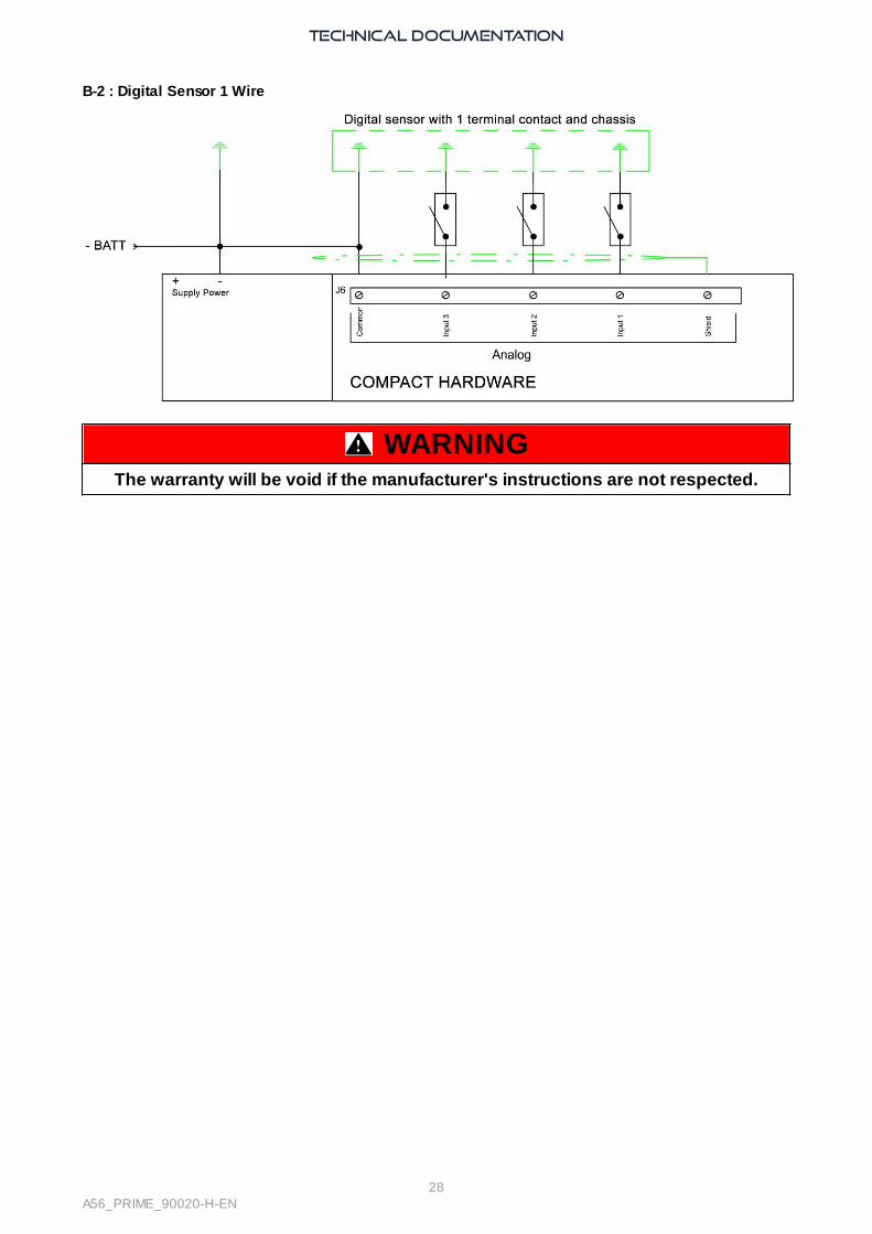
TECHNICAL DOCUMENTATION
28A56_PRIME_90020-H-EN
B-2 : Digital Sensor 1 Wire
WARNINGThe warranty will be void if the manufacturer's instructions are not respected.

TECHNICAL DOCUMENTATION
29A56_PRIME_90020-H-EN
Hysteresis DIHysteresis DI can only be set using i4Gen Suite Software.
For one given Hysteresis DI, it needs three different inputs/output to work:· Two digital inputs are mandatory: one for the low threshold signal and one for the high threshold signal
· One digital output for the hysteresis to activate
First, open the Controller configuration/Inputs menu and select Hysteresis DI. Each hysteresis have thefollowing parameters:
· Hysteresis X enable for DI
· Timer
· Direction
Hysteresis X enable for DI
Enable/disable the hysteresis number X.
TimerThe delay to wait once the condition is met (reaching low/high threshold for X amount of time) to set the digitaloutput.
DirectionFor each hysteresis, two options are available:
Value Label Function
0Set on low threshold,
reset on high
The associated digital output will be set when the low threshold digital inputactivates and it will reset once the high threshold digital input activates.Please not that once the digital output is set, the low threshold digital inputstate will not matter. The digital output state can only change when the highthreshold digital input activates.
1Set on high threshold,
reset on low
The associated digital output will be set when the high threshold digital inputactivates and it will reset once the low threshold digital input activates.Please not that once the digital output is set, the high threshold digital inputstate will not matter. The digital output state can only change when the lowthreshold digital input activates.
setting inputs for your hysteresisTo set a digital input, please refer to Digital Inputs. The functions to use can be found under the Hysteresissection in the search engine.
setting an output for your hysteresisTo set a digital output, please refer to Digital Outputs. The functions to use can be found under the Hysteresissection in the search engine.
TECHNICAL DOCUMENTATION
30A56_PRIME_90020-H-EN
Hysteresis AIHysteresis AI can only be set using i4Gen Suite Software.
For one given Hysteresis AI, it needs two different input/output to work:· One analog input for the measure
· One digital output for the hysteresis to activate
First, open the Controller configuration/Inputs menu and select Hysteresis AI. Each hysteresis have thefollowing parameters:
· Activate Hysteresis on Analog Input X
· Low level threshold
· Timer on low threshold
· High level threshold
· Timer on high threshold
· Hysteresis Direction on Analog Input X
Activate Hysteresis on analog input X
Enable/disable the hysteresis on analog input number X.
Low level thresholdThe low level threshold will be activated on reaching this value and below.
Timer on low thresholdThe delay to wait once the analog input value reaches the low level threshold before activating it.
High level thresholdThe high level threshold will be activated on reaching this value and above.
Timer on high thresholdThe delay to wait once the analog input value reaches the high level threshold before activating it.
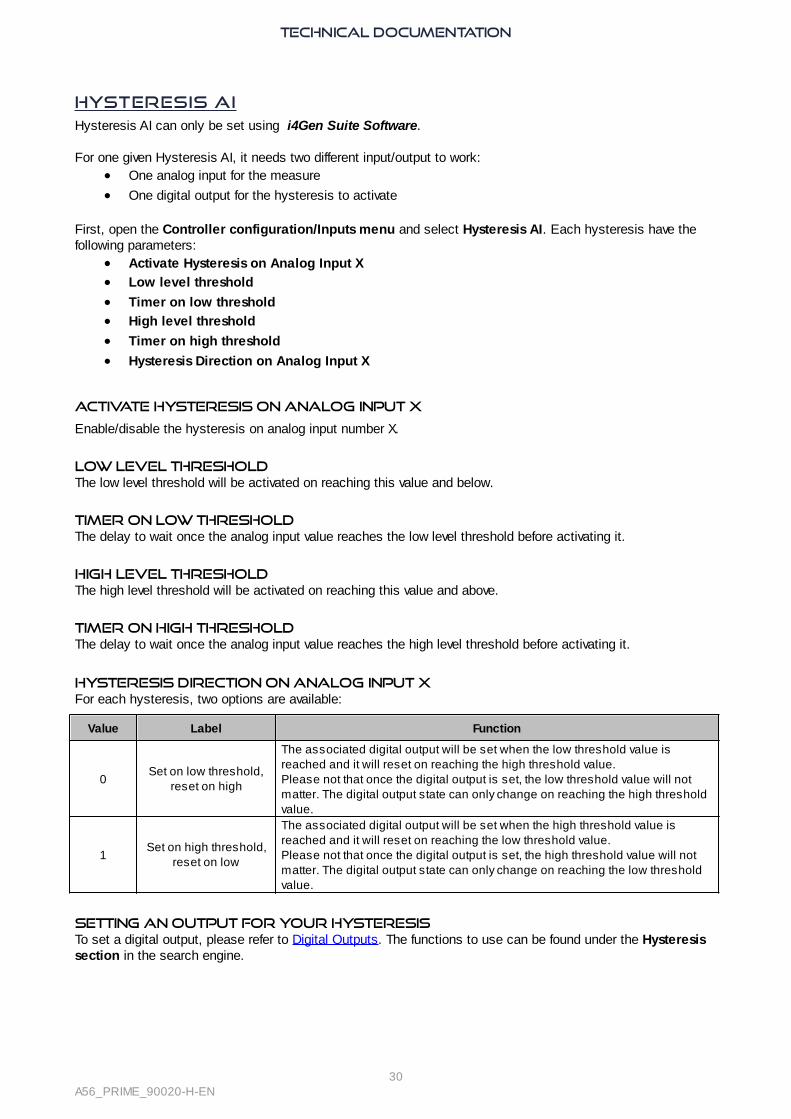
Hysteresis Direction on Analog Input XFor each hysteresis, two options are available:
Value Label Function
0Set on low threshold,
reset on high
The associated digital output will be set when the low threshold value isreached and it will reset on reaching the high threshold value.Please not that once the digital output is set, the low threshold value will notmatter. The digital output state can only change on reaching the high thresholdvalue.
1Set on high threshold,
reset on low
The associated digital output will be set when the high threshold value isreached and it will reset on reaching the low threshold value.Please not that once the digital output is set, the high threshold value will notmatter. The digital output state can only change on reaching the low thresholdvalue.
setting an output for your hysteresisTo set a digital output, please refer to Digital Outputs. The functions to use can be found under the Hysteresissection in the search engine.

TECHNICAL DOCUMENTATION
31A56_PRIME_90020-H-EN
Settings
Engine
Internal start sequence
During the start sequence, the module controls the prelub, preglow, crank and fuel outputs when properconditions are met, whereas the protections are inhibited.This concerns all engine protections.
Main start phases:1. The engine is considered to have started when the speed reaches the crank drop out.2. The engine gets ready.3. The Generator gets ready; the protections are activated unless the "Safety on delay" [2004] is set to
extend inhibition.
Chronogram for Diesel Engine

TECHNICAL DOCUMENTATION
32A56_PRIME_90020-H-EN
Chronogram for Gas Engine
Conditions before start-up
Module monitors the oil pressure and water temperature:1. Oil pre-lubrication check: The oil pressure must be OVER the threshold [3473].
2. Water temperature check: The water temperature must be UNDER the threshold [3474].
Setting thresholds to 0 prevent the module to check those conditions before start-up.Once both values reach there respective threshold, the Air conditioning output is activated (assuming an outputis preset accordingly). When using an external start sequence, if "Engine ready" digital input function is inactive during the duration oftimer [3454], the "Engine not ready" fault will appear.

TECHNICAL DOCUMENTATION
33A56_PRIME_90020-H-EN
Starter
With multiple starters, preset digital outputs to Crank2 and Crank3. The Starter number depends on the presetoutput number. The starters are attempted according to the starter numbers as far as the engine fails to start.
Setting Label Description By default
[3459] Starter order
Starter alternance type:0: one attempt per starterper round (the starters takethe token after oneanother). In i4Gen SuiteSoftware, select“Alternative”.1: each starter makesseveral attempts in a row.In i4Gen Suite Software,select “Consecutive”.
0
[3460] 1st starterNumber of the firstenergized starter.
1
[3461] Start attemptsMaximum count of startattempts allowed by starter.Value: 0…15.
3
Examples with 3 starters, with 1st starter set to 2 and number of start attempts configure to 3:· In alternative mode, the sequence will be 2-3-1-2-3-1-2-3-1.
· In consecutive mode, the sequence will be 2-2-2-3-3-3-1-1-1.
Note: For each starter's functions (starters 1 to 3), in Configuration/Engine/Start/Stop settings there areseparate lower thresholds under which the starter drops out. The values depend on starter type (electric,pneumatic...).
Idle speed
To prevent a cold engine to run at full speed, the module can run it at idle speed for a short time on startup.
For this purpose, the module feeds an idle speed command to the speed controller when:
· The engine is in state Start, Warm up with internal start sequence (according to [3479]).
· Until the Generator is ready with external start sequence.
· The engine is in cooling down (according to [3476]).
The idle speed is fixed by the speed controller. Parameter [3486] allows to indicate to module the idle speed.
Smoke limiter
To prevent a cold engine from over-emitting, the module can feed a smoke limiter command to a speed controller(with smoke limit input) when the module is in states Start, Warm up and Nominal speed.

TECHNICAL DOCUMENTATION
34A56_PRIME_90020-H-EN
External automatic start MODULE
Some engines are equipped with an ASM (Automatic Start Module). On start (AUTO/TEST/MAN mode), themodule empowers it to energize the crank and fuel and to synthesize the engine events.
The setup depends on the type of ASM:
Step Presetting Connections to ASM
1To inhibit the module internal start sequence, activate “External startsequence” in i4Gen Suite Software/Configuration/Engine/Start/Stopsettings
2In i4Gen Suite Software/Configuration/Outputs/Digital relays outputs,preset a digital output to "Start request"
Connect it to a start request input(it replaces the module fueloutput).
3In i4Gen Suite Software/Configuration/Inputs/Digital inputs, preset adigital input to "Remote alarm"
Connect it to an engine alarmoutput.
4In i4Gen Suite Software/Configuration/Inputs/Digital inputs, preset adigital input to “Remote hard shutdown” (immediate engine stop) or“Remote soft shutdown” (stop after cool-down sequence).
Connect it to an engine faultoutput.
Note: As with a module-controlled start, the engine start time-out [3454] applies.
ASM with "Generator ready" output
Step Presetting Connections to ASM
1 In i4Gen Suite Software/Configuration/Input/Digital inputs, preset adigital input to “Generator ready”
Connect it to an engine readyoutput.
Note: When ASM validates the speed, it sends the ready signal, and module regains the control.
ASM without "Generator ready" output
No extra presetting. In absence of Engine fault, at expiry of stabilization timeout [3469], the module declaresthat Generator is ready if the speed and voltage are valid.
Note: ASM without a Generator ready digital output cannot be used with static paralleling or engine starting atidle speed.
Verification
1. Start the Generator in MAN mode , and press
2. Check that the delays (pre-lubrication, preheating, stabilization,...) correspond to yourexpectations.
3. If you wish to simulate the starter and oil pump sequences, disconnect the corresponding outputs.Navigate in the Display/Inputs/Outputs menu where the status of the outputs is displayed in realtime, then, check the activation of the starter and the fuel.
4. Check that the Generator led lights up.5. Check that the engine speed and that the Generator voltages are stable (e.g.: 1500rpm, 50Hz,
400VAC); the data are visible in the Display menu.

TECHNICAL DOCUMENTATION
35A56_PRIME_90020-H-EN
Speed/Voltage Control
Introduction
The module allows speed or voltage control with the following possibilities:
· Correction with two analog signals (speed and voltage) +/- 10VDC with amplitude and adjustable offset.
· Correction with pulses output (+speed/-speed and +V/-V).
· Correction with J1939 frames only for speed.
[4405] is the speed/KW correction applied to speed governor (value given in percent).
[4411] is the voltage/KVAR correction applied to voltage regulator (value given in percent).
Follow carefully the configuration procedures (amplitude and offset adjustment) in this chapter in order toobtain efficient synchronization, load sharing and droop mode.
Analog output for speed controller
The speed output sends the required frequency set-point to the speed controller during synchronization and KWcontrol (load sharing, ramp up/down). The voltage output -10V...10VDC must be adjusted in amplitude andoffset to allow the module to vary the speed regulator set-point in a proper range; in order to control the speed ina band of +/- 2.5Hz around the nominal frequency.
1. Start the Generator in MAN mode by pressing and then .
2. Adjust the speed value on the speed governor to get the nominal frequency 50Hz (or 60Hz).
3. Connect the speed output and speed common terminal. Adjust the offset parameter to obtain a frequency of50Hz (or 60Hz).
4. Increase manually the engine speed at its maximum (100%) by pressing + , then adjust the
amplitude to obtain a frequency of 52.5Hz (or 62.5Hz).
5. Return to a 0% speed correction by pressing + , then adjust the offset again if necessary to
obtain a 50Hz (or 60Hz) frequency.
6. Change the speed correction to minimum (-100%) by pressing + and check that the frequency
is 47.5Hz (or 57.5Hz).
7. Return to 0% speed correction by pressing + .
8. Press to stop the Generator.
The application note COMPACT PLATFORM_SPEED GOVERNOR WIRING ADJUSTMENTS_EN gives the
parameters to be set for several speed governor models. To use the module with other models, adjust the
amplitude and offset according to explications above.

TECHNICAL DOCUMENTATION
36A56_PRIME_90020-H-EN
Analog output for voltage regulator
The voltage output sends the required voltage set-point to the voltage regulator during voltage synchronizationand reactive load sharing. The voltage range -10V...10V must be adjusted in amplitude and offset to allow themodule to vary the voltage regulator set-point in a correct range; in order to control the voltage in a band of +/-30V around the nominal phase-phase voltage:
1. Start the Generator in MAN mode by pressing the then buttons.
2. Adjust the voltage value on the voltage regulator to get a nominal phase-phase voltage of 400V (or 480V).
3. On the module, connect the AVR output and AVR common terminal. Adjust the offset to obtain a voltage of400V.
4. Increase manually the Generator voltage at its maximum (+100%) by pressing + then adjustthe amplitude to obtain a voltage of 430V (or 510V).
5. Return to a 0% voltage correction, then adjust the offset again if necessary to obtain a voltage of 400V.
6. Change the voltage correction to minimum (-100%) by pressing + to check that the voltage is370V (or 450V).
7. Return to 0% voltage correction.
8. Press to stop the Generator.
The application note COMPACT PLATFORM_AVR-DVR WIRING ADJUSTMENTS_EN gives the parameters tobe set for several AVR models. To use the module with other models, adjust the amplitude and offset accordingto explications above.
Speed/Voltage controlled by Contacts/Pulses
When digital outputs are connected to the speed governor and/or AVR, the module changes the state of theseoutputs according to the result of the current PID:
A digital potentiometer converting pulses into analog values can be used. A digital potentiometer has its ownparameters: DU0 (fsd) and timer.
In i4Gen Suite Software/Configuration/Outputs/Digital outputs/relays, set the respective functions(increase/decrease speed by pulse and increase/decrease voltage by pulse) to the desired +Speed/-Speed and+V/-V outputs.
A pulse is generated when the absolute value of the correction applied exceeds the dead band. The larger thecorrection signal ([4405] for speed and [4411] for voltage), the longer the pulses are and the shorter the timebetween each pulse is. The Pulse divider parameter is used to reduce or increase the pulse length for thesame correction value.

TECHNICAL DOCUMENTATION
37A56_PRIME_90020-H-EN
1. Adjust the speed/voltage regulator to its nominal value (unless the controller module connection is direct).2. If the Generator makes too much or too little correction during an active phase (synchronization, load
sharing...), the Pulse divider is not adapted:
· Decrease [3652]/[3653] to reduce the action on the regulator.
· Increase [3652]/[3653] to increase the action on the regulator.3. If the Generator oscillates around the set-point or fails to reach the set-point, the dead band is not adapted:
· Decrease the dead band [3650]/[3651] to improve accuracy around set-point.
· Increase the dead band [3650]/[3651] if the Generator oscillates in frequency or power.4. If a digital potentiometer is connected between the module and the regulator, set ΔU (fsd) and the delay
time; if the compensation is not as expected, check the following points:
· Is the potentiometer active when the module sends a signal ?
· Is the range managed by the potentiometer sufficient ?
Note: If each pulse causes overcompensation, the potentiometer engine may have continued to run even in theabsence of a pulse. A shunt resistor on the potentiometer input can correct this problem by forcing a low levelon the input in the absence of pulse.

TECHNICAL DOCUMENTATION
38A56_PRIME_90020-H-EN
Circuit Breakers
Circuit breaker operating modes
Two logic outputs (relay or transistor) are used to control the circuit breakers - 1 for opening and 1 for closing.These outputs allow different types of circuit-breakers to be controlled.The settings are accessible from i4Gen Suite Software/Configuration/Outputs/Generator Breaker
ADVICEUSEFUL INFORMATION
§ Adjustment tip
§ Using the module
Failure to comply with these recommendations may cause the module to malfunction.
Note: Never switch from one operating mode to another while the plant is running.

TECHNICAL DOCUMENTATION
39A56_PRIME_90020-H-EN
Circuit breaker control mode
Value Mode Circuit breaker chronogram
01: Continuous contact to open.2: Positive pulse to close.
11: Continuous contact to open.2: Continuous contact to close.
21: Under-voltage (MN) coil opening.2: Pulse to close.
31: Under-voltage coil opening.2: Continuous contact to close.
41: Pulse to open.2: Pulse to close.
51: Pulse to open.2: Continuous contact to close.

TECHNICAL DOCUMENTATION
40A56_PRIME_90020-H-EN
Pulse configuration
The settings can be accessed from i4Gen Suite Software.
Positive Pulse
Configuration/Outputs/Generator Breaker.For the positive pulse control of the Generator breaker, set the parameter [2301].
Coil Control
Configuration/Outputs/Generator Breaker.For fail-safe control, set parameters [2302], [2303] for the Generator breaker.
To detect the position of the circuit breaker, a logic input must be configured as:
Function Value
Circuit breaker position feedback 1 = circuit breaker closed (LED displayed on the front panel).

TECHNICAL DOCUMENTATION
41A56_PRIME_90020-H-EN
Configuration of circuit breaker commands
Two logic outputs (relay or transistor) must be configured as described in the table below and connected to thecircuit breaker.
Function Description
Close circuit breaker control Closing the circuit breaker (continuous, pulse, MNcoil).
Open circuit breaker control Opening the circuit breaker (continuous, pulse, MNcoil).
Verification
DANGERRISK OF ELECTRIC SHOCK, EXPLOSION OR ARCING
§ The module may only be installed and maintained by qualified electricians.§ Use personal protective equipment (PPE)§ Follow good safety practices for electrical work.§ Turn off the power before installing or replacing a fuse, and before installing the module.§ Use equipment adapted to check the absence of voltage.§ Do not use a resettable fuse.Failure to follow these recommendations may result in death or serious injury.
Follow these instructions in order to check the Generator breaker:
1. Connect the circuit breaker controls and check the breaker feedback.
2. Start the Generator in MAN mode (press ), and press .
3. Press (Generator breaker) when the Generator is ready (Check that there is no voltage on the other
side of the breaker before closing).4. Check that the Generator circuit breaker is closed and that the Generator circuit breaker LED is lit.5. If possible apply a load bank (active and reactive) on the Bus and check the powers, currents, voltages and
cos (ϕ).
6. Press (Generator breaker) to open the Generator breaker.
7. Check that the Generator circuit breaker is open and that the Generator circuit breaker LED is off.
8. Press to stop the Generator.

TECHNICAL DOCUMENTATION
42A56_PRIME_90020-H-EN
Synchronization
Functioning
The module launches the synchronization only if the Bus provides at least 80% of the nominal voltage. Itmanages a correction on frequency and voltage to go and stay on the acceptance windows (can be handled inSynchronization). When the Generator voltage and the Bus voltage are synchronized, the module allows toclose the circuit breaker.
In case of synchronization fails, the action can be set with the variable [2804] inConfiguration/Synchronization.Another module is elected if load dependant start stop mode is selected.
Condition
Voltage acceptance [2800].Frequency acceptance [2801].Phase angle acceptance [2802].C2S dwell time (Synchronization dwell time before authorizing to close the breaker) [2809].
Visualizing
Label Description Variables
Phase sequencematch
Phase sequence match allowing to close the circuit breaker. [306]
Voltage match Voltage match allowing to close the circuit breaker. [307]
Frequency match Frequency match allowing to close the circuit breaker. [308]
Phase match Phase match allowing to close the circuit breaker. [309]
Authorization to closebreaker
Authorization to close the circuit breaker. [310]
Chronogram
Adjustments
Prerequisite: The speed and voltage outputs control must be set as described in Speed/voltage control.

TECHNICAL DOCUMENTATION
43A56_PRIME_90020-H-EN
The voltage and the frequency of the Bus must be in their nominal value.The PID parameters can be set using Configuration/Control Loop.
Adjustment procedureDANGER
RISK OF ELECTRIC SHOCK, EXPLOSION OR ARCING
§ The module may only be installed and maintained by qualified electricians.§ Use personal protective equipment (PPE)§ Follow good safety practices for electrical work.§ Turn off the power before installing or replacing a fuse, and before installing the module.§ Use equipment adapted to check the absence of voltage.§ Do not use a resettable fuse.Failure to follow these recommendations may result in death or serious injury.
1. Disconnect the Generator circuit breaker control output on the module.2. Make sure that there is some voltage on the Bus side. The Bus LED should be lit.
3. Press to be in MAN mode.
4. Start the Generator by pressing and check the Display/Synchronization page.
5. Press (Generator breaker) in order to start the synchronization.
6. The Generator should synchronize within 5 seconds. If it is not the case, isolate the cause (voltage,frequency or phase). Depending on the source of the issue (voltage, frequency or phase) change thecorresponding PID parameters available in Configuration/Control loops: Control loop PID chapter to seehow to manage PID settings.

TECHNICAL DOCUMENTATION
44A56_PRIME_90020-H-EN
Verification
1. Disconnect the circuit Generator breaker control output on the module. 2. Make sure that there is voltage on the Bus side. The Bus LED should be lit.
3. Press to be in MAN mode. Start the Generator by pressing and check the
Display/Synchronization page.
4. Press (Generator breaker) when the engine is ready.
5. Press to go to the Information page and check if the module is in synchronizing mode.
6. Go to Display/Synchronization and check the phase difference. When the phase difference is 0° followthe instructions bellow:
· Check the rotating fields and the concordance of the phases upstream and downstream of thecircuit breaker.
· Check the wiring of the Generator and Bus voltage references.
· Check the potential difference between Ph1 Gen and Ph1 Bus. The potential difference must bebellow 10% of the nominal voltage. Check the potential difference between Ph2 Gen and Ph2 Busas well.
7. Stop the Generator by pressing .
8. Reconnect the circuit Generator breaker control.
9. Start the Generator by pressing .
10. Press (Generator breaker) when the engine is ready. The Generator should synchronize and then
close its Generator breaker.

TECHNICAL DOCUMENTATION
45A56_PRIME_90020-H-EN
Control on dead bus management
In case of an emergency start of the Power plant (no voltage on the common Bus-bar), the units communicatethrough CRE-Link® to elect a module which will close first its circuit breaker on the Bus-bar: it is the arbitrationprocedure, to avoid closing 2 circuit breakers at the same time, when the generators are not synchronized.With a failure of the CRE-Link® communication, the units switch on a safe mode to protect the circuit breakerclosing procedure. Each closing commands will be delayed depending on the number of the unit.
Formula:
Generator #n will close its circuit breaker after ([2306]/10) + (7 * n) seconds.[2306]: Delay to close breaker if there is a CAN bus fault. Default value: 15.0s.

TECHNICAL DOCUMENTATION
46A56_PRIME_90020-H-EN
Load/Unload Ramp
Functioning
After a synchronization, the module ramps up the Generator load (soft transfer) to avoid overload or a loadimpact (hard transfer).The module calculates the average of the active power read from the CRE-Link® CAN bus. It then starts a loadramp to progressively reach this value (KW regulation). During the ramp, the module keeps a constant power factor, set by the Bus power factor before closing theGenerator breaker, in order to start a reactive power ramp.If the production request is stopped, the module starts an unload ramp to progressively reach the Generator lowlimit.
The parameters to be set are the following: Generator Low limit [2866], Generator High limit [2867] Load ramptime [2853], Unload ramp time [2856]. The timers [2853] and [2856] correspond to the time required to reachthe nominal load.
Example: Power rating of the Generator = 500KW, Load Ramp time = 50 seconds, Unload Ramp time = 22seconds:
Before stopping the Generator, the module reduces its load to the low limit and then opens the circuit breaker.If the breaker opening fails at the end of the ramp, the Generator continues to share the load and shows abreaker opening fault on display.
Adjustments
Prerequisite: The speed and voltage outputs control must be set as described in Speed/voltage control.The PID settings parameters are settable in the menu Configuration/Control Loops.
Verification
For this test, an available load is important. After the synchronization sequences, the module switches to power management mode.1. Check that the power measured per phase is positive and balanced.
o Go to Display. Otherwise check the currents connections.2. Check that the current power follows the set-point of KW or KVAR during ramps.
o Go to Configuration/Control Loops/KW-control and Configuration/Control Loops/KVAR-control. Change the settings if necessary.

TECHNICAL DOCUMENTATION
47A56_PRIME_90020-H-EN
Regulation KW/KVAR
Functioning
The module switches to the regulation mode on KW and on KVAR around its set-point after a load ramp.
The module calculates the active and reactive power it should supply using the information received from theCRE-Link®. Each module provides an active and a reactive power according to its nominal power.
Example:On a Power plant with two generators, Generator 1 with a nominal power of 100KW and Generator 2 with a nominal power of 200KW: Generator 1 willtake 33.3% of the active power of the Bus load while Generator 2 will take 66.6% of the active power of the Busload.The KW/KVAR and frequency/voltage regulations are controlled by two PID controllers. It allows the module tocorrectly get to its KW/Frequency and KVAR/Voltage set-points by controlling the speed controller and the AVRsystem. The PID controllers are summarized by the figure bellow:
Note: A similar PID controller regulates the reactive power and the nominal voltage by controlling the AVRsystem. The Global Gain for Nominal Voltage centering is the parameter [2958].
The PID parameters can be found in i4Gen Suite Software/Configuration/Control Loops or inConfiguration/Control Loops. The frequency/voltage and the KW/KVAR are controlled simultaneously. The higher the parameters [2914] and[2958] are, the higher the frequency/voltage error will have an impact on the controller.To know how to correctly set up the PID parameters in order to have a correct regulation, see Control loop PID.
Adjustments
Prerequisite: The speed and voltage outputs control must be set as described in Speed/voltage control.The PID controller adjustment must be set as described in Control loop PID.On all units, adjusting the regulation is needed in order to have an acceptable response time, and a perfect stabilityin KW or KVAR regarding load and different sequences.
In case of an unbalanced load sharing:1. Check that the measured power for each phase is positive and balanced in the Display/Generator.
Otherwise check the wiring direction of the current transformers.2. Check that the speed/voltage control is set (amplitude for speed and voltage correction, must be maximum
at +/- 8% of nominal value).3. Check that all Generators are stable. If one or more Generators oscillate in frequency/voltage (even slightly),
this oscillation may affect the load sharing. Keep in mind that an instability on the speed governor or the AVR

TECHNICAL DOCUMENTATION
48A56_PRIME_90020-H-EN
system cannot be corrected by PID on the module.

TECHNICAL DOCUMENTATION
49A56_PRIME_90020-H-EN
Protections
Functioning
The protections are triggered by an internal or external event (alarms, faults, logic inputs, CAN bus loss, etc.). Inorder to protect the process, engine or alternator, an action must be associated with the events. These actionsare of different kinds:
· They can just raise an alarm; warning can be viewed on the LCD screen (ANSI30); a report can be retrieved.
· They can protect the equipment: the engine stops, the circuit breaker opens safely... and can activate anoutput.
· They can use an alternative solution (reconfiguration) that we will call Fallback.
The action is a protection configuration: CT parameter or control of an inter-module CAN bus loss (alternativesolution). The droop actions and the value 10 can be used in case of CAN bus problem, for example:
· When an other product is missing: Missing product.
· When the communication with the other products is down: Isolated product.
· When a MASTER type module is missing: Missing MASTER.
Value Type Action Description
0 – Off (no action) –
1 Fall-back Generator electrical fault
The protection opens the Generator circuit breakerand tries to re-synchronize again after the timer[2806]. The number of resynch attempts is set by variable[2807], it means that if the fault that has tripped theGenerator circuit breaker is happening again aftereach attempt, the Generator will be stopped. Thenumber of attempts is reset with the reset function.
3 Alarm AlarmNotice as alarm on front panel, displayed informationonly, no action.
4 Fault Fault (soft shutdown)Generator circuit breaker opens allowing the engineto cool down for the duration of the cool down timer,before to stop.
5 Security Security (Hard shutdown)Generator breaker opens and engine stopsimmediately without cooling down; "serious fault"shows as information.
6 Fall-back Fault (soft shutdown) + Help
+ Help means the faulty Generator will ask anotherGenerator to start through CRE-Link® to replace it,once the new Generator is available, the faultyGenerator stopped according to the settings wait forreset. In case there are already enough Generator onthe Bus to support the load supply by the faultyGenerator, the input is considered as normal faultand there is no extra Generator starting or available.
7 Fall-back Generator electrical fault + Help
+ Help means the faulty Generator will ask anotherGenerator to start through CRE-Link® to replace it,once the new Generator is available, the faultyGenerator is tripped according to the settings andtries to resynchronize or stop and wait for reset. In case there are already enough Generator on theBus to support the load supply by the faultyGenerator, the input is considered as normal faultand there is no extra Generator starting or available.
8 Fall-back Droop + AlarmFor CRE-Link® failure only: The load control is switchon droop mode and an alarm is triggered.
9 Fall-back Droop + No start if static parallelingFor CRE-Link® failure only: the load control is switchon droop mode and an alarm is triggered, the static
TECHNICAL DOCUMENTATION
50A56_PRIME_90020-H-EN
Value Type Action Description
paralleling is disabled but the dynamic parallelingremains active.
10 Backup No start if static parallelingThe static paralleling is disabled but the dynamicparalleling remains active.
These actions have to be configured with i4Gen Suite Software. List of potential alarms/faults can be downloadedvia i4Gen Suite Software/System/PC transmit/receive: List of actions on alarms-faults.
A digital output can be configured to indicate that the protection is active.Note: The protections are active whatever the operating mode is (MAN, AUTO, TEST).
All the protections available for the product are explained in the protection chapter Software variables.Specific protections are explained below.
Emergency stop
The emergency stop function can be performed in two ways:o Connect an Emergency stop button to an Emergency stop logic input. It is a purely software
solution. It is a software treated emergency stop.o Action on alarm/fault: select Emergency stop.
Note: A physical disconnection of the circuit line of all starters, circuit breakers commands and fuel commandhas to be wired in the cabinet in addition of the module emergency stop management.
Communication
Alarm/Fault Description Setting
CANopen Communication error on CANopen. [3058]
J1939 Communication error on J1939. [3059]
For CRE-Link® errors, check CRE-Link®.
Breaker
Depending on the status of the module, an alarm or circuit breaker fault may occur. This can be a failure closingcircuit breaker, failure opening circuit breaker, unexpected opening of the circuit breaker, unexpected closing ofthe circuit breaker.Alarm or fault depends of the severity of the event.
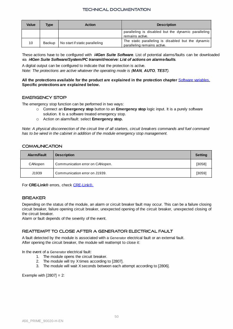
Reattempt to close after a Generator electrical fault
A fault detected by the module is associated with a Generator electrical fault or an external fault.After opening the circuit breaker, the module will reattempt to close it:
In the event of a Generator electrical fault:1. The module opens the circuit breaker.2. The module will try X times according to [2807].3. The module will wait X seconds between each attempt according to [2806].
Exemple with [2807] = 2:

TECHNICAL DOCUMENTATION
51A56_PRIME_90020-H-EN
Generator electrical fault
Generator breaker position
Generator status with respect tocoupling
Count of re-synchr. launches
Audible or visual warning device
To trigger an external alarm when a protection trips, connect the alarm to a logic output configured as a "Horn". The signal duration is configurable by [2478] (0 means that the alarm will be activated until manual shutdown);alternatively, an input can be configured as "Horn Off" to manually stop the horn:
Alarm/fault reset
To perform an alarm/fault reset:
- Locally: +
- Remote: use the "Reset faults" input function.
Request for help
The module can request help from another Generator to replace it when an internal fault configured as protection6 or 7. This request can also come from the activation of a logic input configured as a help request. The two functions/protections differ in their stop sequence:
· Fault (soft shutdown) + Help: The faulty Generator will ask another Generator to start through CRE-Link®to replace it, once the new generator is available, the faulty generator stopped after cool down accordingto the settings and wait for reset. In case there are already enough generator on the Bus to support theload supply by the faulty generator, the input is considered as normal fault and there is no extra generatorstarting or available.
· Generator electrical fault + Help: The faulty Generator will ask another generator to start through CRE-Link® to replace it, once the new generator is available, the faulty generator is tripped according to thesettings and tries to resynchronize or stop and wait for reset. In case there are already enough generatoron the Bus to support the load supply by the faulty generator, the input is considered as normal fault andthere is no extra generator starting or available.

TECHNICAL DOCUMENTATION
52A56_PRIME_90020-H-EN
Control Loop PID
eMPIRICAL PID GAIN TUNING
1. Set all the gains to 0 (except G gain).2. Increase the P gain until you have a stable oscillation.3. Increase the D gain until the oscillation is canceled.4. Repeat steps 2 and 3 until the D gain can't cancel the oscillation caused by the P gain.5. Go back to the previous values of the P and D gains where the D gain cancels the oscillation caused by the
P gain.6. Increase the I gain in order to correct the error between the actual value and the set-point. Warning: A too
high I gain might cause oscillations to the system. The I gain must correct the static error rapidly withoutoscillations (or small oscillations in order to gain some response time).

TECHNICAL DOCUMENTATION
53A56_PRIME_90020-H-EN
Advanced Settings
Droop
Functioning
In order to maintain load sharing, the droop is used in the case of the following CRE-Linkâ problems:
· Isolated product (if [3052] is set to 8 or 9).
· Missing product (if [3054] is set to 8 or 9).
· Missing MASTER/BTB (if [3057] is set to 8 or 9).
· Mismatch version.
It can be forced by changing the GPID mode parameter [2013]. As droop is allowed, the control does not useany integral.
Frequency DROOP
Speed droop = (Rated no-load frequency – Base frequency)/Rated no-load frequencyIn the Power plant, the Generators were requested to run in proportion to their rated power i.e. with the sameP/P0. As they are set with the same droop, they share the same droop characteristic. As the load demandincreases, they respond to the fall in frequency by increasing their active power outputs simultaneously. Theincrease in the active power output counteracts the reduction in frequency. Thus they do not fight one anotherto control the load (no "hunting").
Voltage droop
Use of voltage instead of frequency.
The droops are set in the module units, not in the ESGs/AVRs:
All the module units must be set to the same relative deviations [2204] and [2250].
CAUTION
Follow strictly, throughout the aggregate, the adjustment procedures (amplitude -offset) in order to have thebest load sharing in droop.
TECHNICAL DOCUMENTATION
54A56_PRIME_90020-H-EN
Load Dependent Start/Stop
Functioning
This function allows to automatically start and stop Generators of a Power plant according to the load variation.This prevents overload (you are advised to run generators between 70 and 85%). CRE-Linkâ makes it possibleto share load information and coordinate the actions.Conditions required by automatic start/stop:
· The remote start must be permanently active on each module unit; otherwise, the Generator cannotstart. This is the prime trigger.
· At least two generators must be equipped with a module unit, all with identical Load DependantStart/Stop settings.
· All the module units must be in AUTO mode.
The settings are in i4Gen Suite Software/Configuration/Power management system/Load dependentstart/stop.
Note: if a BTB COMPACT is used in the Power plant, load dependent start/stop will be applied separately oneach segment.
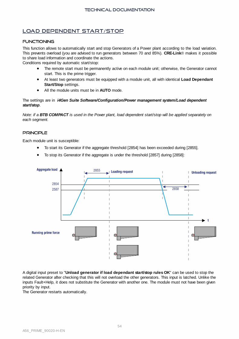
Principle
Each module unit is susceptible:
· To start its Generator if the aggregate threshold [2854] has been exceeded during [2855].
· To stop its Generator if the aggregate is under the threshold [2857] during [2858]:
A digital input preset to "Unload generator if load dependant start/stop rules OK" can be used to stop therelated Generator after checking that this will not overload the other generators. This input is latched. Unlike theinputs Fault+Help, it does not substitute the Generator with another one. The module must not have been givenpriority by input.The Generator restarts automatically.

TECHNICAL DOCUMENTATION
55A56_PRIME_90020-H-EN
Example
A 4x100KW Power plant with a load that increases linearly from 0 to 400KW, then decreases to 0KW.Start threshold [2854] is set to 80% and the stop threshold [2857] is set to 20%.Generator #1 is permanently running. When load increases above the start threshold, Generator #2 starts tosupplement Generator #1, then Generator #3 and Generator #4 start. As the load decreases, the generators arephased out in the order 4, 3, 2.
Start-stop by Generator Number
If this way is selected on all module units in the Power plant, the automatic start/stop phasing is based on theGenerator numbers, set in i4Gen Suite Software/Configuration/General [2001]:
1. The Generator with the smallest number will start first and run onwards forcefully.2. On increasing load demand, the next starts are ruled by the Generator number.3. On decreasing load demand, the generators are phased out in the reverse order.
Note: If a Generator has been started forcefully in MAN mode, it overrides the smallest Generator number. Itcloses its breaker on the Bus-bar, even if there is no load (dead bus management=Yes). The next Generator tostart is the one with the next smallest number.

TECHNICAL DOCUMENTATION
56A56_PRIME_90020-H-EN
Start-stop by Running Hours
If this way is selected, the Generator to start/stop is auto selected according to the module running hourmeter:
· On increasing load demand, the next Generator to start is the one with fewest running hours.
· On decreasing load demand, the next Generator to stop is the one with most running hours.
Note: If a Generator starts and goes past the hours run by a Generator which is stopped, the first one does notimmediately stop and the second one immediately starts. Coordination between generators is activated only ona load/unload request, i.e. in the next start/stop on-load request on CRE-Linkâ.
Start-stop by Generator Priority Number
If this way is selected on all module units in the Power plant, the automatic start/stop phasing is based on theGenerator priority numbers, set in i4Gen Suite Software/Configuration/Power management system/Loaddependent start/stop [2863]:
1. The Generator with the smallest number will start first and run onwards forcefully.2. On increasing load demand, the next starts are ruled by the Generator priority number.3. On decreasing load demand, the generators are phased out in the reverse order.
Note: If a Generator has been started forcefully in MAN mode, it overrides the smallest priority number. Itcloses its breaker on the Busbar, even if there is no load (dead bus management=Yes). The next Generator tostart is the one with the next smallest number.
Start-stop Cyclic Rotation
If this way is selected, the automatic start/stop is based on the number of operating hours of the generators: · On increasing load demand, the next Generator to start is the one with fewest running hours.
· On decreasing load demand, the next Generator to stop is the one with most running hours.
· On a difference in operating hours between 2 generators greater than the parameter [2865], the Generatorwith the fewest running hours starts up, synchronizes and carries out a load ramp. Once this Generatoris on the Bus, the Generator with the most running hours unloads and opens its circuit breaker.
Start-stop Cyclic Rotation (Custom Counter)
The principle is the same as "start/stop cyclic rotation" but the system uses an auxiliary hours counterinstead of the operating hours one.

TECHNICAL DOCUMENTATION
57A56_PRIME_90020-H-EN
Static Paralleling
Cases STUDY
· Starting a full plant with multiple generators in an emergency on dead bus: the generators are ready totake load in the shortest possible time, without warm-up.
Bottom line: full plant availability in less than 10s typically. This meets the NEC700 requirements.· Installation with a high voltage transformer: as the Generator(s) start, the transformer core is
magnetized progressively, without peaks (no transient short-circuit).
Note: As long as there is a voltage on the Bus, the dynamic paralleling prevails even if static paralleling isconfigured.
Conditions
On equipment:· The alternators are identical (in particular, same winding pitch).
· The AVRs are set for static paralleling: they wait for excitation command on their first start.
· All breakers must be powered by continuous voltage like 24VDC or 48VDC (so as to close before ACis available).
On module:· The remote start is activated.
· A digital output is preset to Excitation command.
Setting Label Default Description
[2050] Paralleling mode Dynamic Set it to static
[2051] TM max excit 30.0sTimeout for excitation. This parameter must take care ofthe timer; prelubrication, preglow, starter, speedstabilization. See sequence further.
[2053] Excit. speed 90.0%Speed threshold in % of nominal speed before waitingexcitation. This threshold must be identical in all units.
[2054] Excit. volt. 20.0%
Voltage threshold in % of nominal voltage to validateclosing breaker in static paralleling. It relates to theremanent voltage of the alternators. Must be identical inall units.
[2056] TM Volt stab. 5.0s
Voltage stabilization timer after excitation order before topronounce as engine ready. This timer must be identical in all module units. Duringthis stabilization, the units are working in droop mode.

TECHNICAL DOCUMENTATION
58A56_PRIME_90020-H-EN
Sequence
The generators are synchronized through CRE-Link®:
1. All remote start are activating at the same time. 2. All the module units close their breaker and start their engine. 3. The remanent voltage appears.4. The fastest Generatorʼs speed reaches [2053]. 5. The slowest Generatorʼs speed reaches [2053] before [2051] expires; then CAN bus orders all the module
units to simultaneously activate their excitation output; as a result:
· The nominal voltage is reached immediately at the same time on all generators.
· The plant can run at full capacity.

TECHNICAL DOCUMENTATION
59A56_PRIME_90020-H-EN
Load Shedding
Functioning
The load shedding is the ability to disconnect less important consumers if the Power plant is overloaded evenwhen the full capacity is engaged; this prevents a blackout.Any module – generally one – in the Power plant can take care of excessive demand. If the KW demandexceeds the Power plant capacity and/or the frequency has dropped below a threshold for a given time, thededicated module activates outputs to shed non-essential loads.Using two levels of thresholds and delays, you can setup your system to react more or less rapidly dependingon the severity of the situation.
Settings
All the settings are explained in Software variables.They are set in i4Gen Suite Software/Configuration/Power management system/Load shedding.Using i4Gen Suite Software/Configuration/Outputs/Digital outputs/relays, preset up to 5 outputs to x non-essential trip.In the same manner as for protections, you can trigger an action when the shedding capacity runs out (aspecific output Trip alarm is signaled if [2862] = 3).
Sequence
When one of the two levels is reached and its associated delay has expired, a trip alarm is set and a five-tiershedding starts (level 1) or escalates (level 2): at the end of a cycle based on [2861] an extra non-essentialconsumer is phased out till the threshold is reversely passed. When the KW demand exceeds the supply, or when the frequency drops:
1. Trip alarm is raised after the related delay, as long as one of the threshold is exceeded.2. The Trip outputs are raised in a sequence after an extra delay; they are latched till a manual or
automatic reset; it can raise an output preset to non-essential direct trip.

TECHNICAL DOCUMENTATION
60A56_PRIME_90020-H-EN
The charts show the trip alarm and trip outputs depending on the Generator load or frequency:
The trip counter sums the times during which at least one consumer is shed. It is reset at the same time as thealarm:

TECHNICAL DOCUMENTATION
61A56_PRIME_90020-H-EN
Maintenance Schedule
Use
The configuration of the maintenance schedule is carried out from the i4Gen Suite Software.The consultation is done in Display/Maintenance ("off" means that the servicing cycle is not defined).When a cycle has elapsed, an alarm is displayed and the module's alarm LED flashes.In the module alarm page you can view the expired cycle.Resetting the alarm restarts the servicing cycle.
Engine running hours Maintenance cycles
The counter is decreased according to the number of operating hour(s) of the engine:1. Rename the cycle if necessary.2. Set the number of hour(s).3. Press the Reset button to reset the counter.
Daily Maintenance cycles
The counter is decreased according to the number of days passed. Without taking into account the Generatorrunning hours:1. Rename the cycle if necessary.2. Set the number of day(s).3. Press the Reset button to reset the counter.
Note: Maintenance cycles are saved on a non volatile memory.
TECHNICAL DOCUMENTATION
62A56_PRIME_90020-H-EN
Power Plant Application
Load Sharing
General information
The module is informed of the load measurements of the other Generators via CRE-Link®.They distribute the load in proportion to their rated power. This distribution method is more reliable and accurate than an analog solution. Speed control is used to distribute the active load. Voltage control is used to distribute reactive power.
Available measures:
Label Description Variables
KW GEx Active power as percentage of nominal. [400] to [431]
KVAR GEx Reactive power as a percentage of nominal. [465] to [496]
KW nom GEx Rated active power for each Generator. [433] to [464]
KVAR nom GEx Rated reactive power for each Generator. [498] to [529]
The active and reactive powers taken by the Generators in distribution are visible in i4Gen Suite Software oron the module screen.
Settings
· Enter the number of Generators and the number of each Generator.
· Set the speed and voltage outputs as explained in Speed/voltage control.
· Enter the characteristics of your application (rated power, PT ratio, CT ratio, etc...).
· Set circuit breaker closing conditions ( i4Gen Suite Software/Configuration/Synchronization).
· Adjust the synchronization by adjusting the PID in frequency, voltage and phase (see Synchronizationchapter).
· Set the KW and KVAR ramps by adjusting the KW and KVAR PIDs (see Load/Unload ramp).
· Check the distribution in KW and KVAR (control set during ramps). KW and KVAR must remain within therange of 2% around the plant average. (see Control KW/KVAR).
Note: The average KW/KVAR of the Power plant in % as well as the KW/KVAR measurements of theGenerator in % can be viewed on the setting screen during the distribution.

TECHNICAL DOCUMENTATION
63A56_PRIME_90020-H-EN
Operating mode
MAN
1. Press : the associated LED lights up.
2. Press : the module starts the Generator.
3. Press to move the Generator to the load. Depending on the configuration, the sequence may
vary:
· synchronization (if a voltage on the Bus-bar is present).
· circuit breaker closing.
The module controls the load according to the configuration (distribution, droop).
1. Press so that the Generator leaves the load; this may involve an unload ramp (if at least one
Generator supplies the load) then a breaker opening the engine continues to run.
2. Press
· Once: to cool the engine and stop it when the time delay has expired.
· Twice: to stop the engine directly.
Pressing , when the circuit breaker is closed, initiates an unload sequence, opens the circuit breaker and
stops the engine after the cooling delay.
Note: MAN mode does not allow +/- fast or +/- voltage to synchronize or load control.
In MAN mode, it is possible to start/stop the engine and control the speed/voltage:

TECHNICAL DOCUMENTATION
64A56_PRIME_90020-H-EN
Local key Substitution function
/ Manual start / manual stop
+ /Entry + speed/ Entry - fast OR Entry +U/ Entry -U
AUTO
AUTO mode requires the use of a logic input configured as Remote start.Until the digital input is activated and the delay has expired, the AUTO mode is not active. If the input isdeactivated, the module is considered unavailable during Start/stop depending on load management.

TECHNICAL DOCUMENTATION
65A56_PRIME_90020-H-EN
Advanced FunctionsFor more information about Easy Flex, Alternative selection and Scheduler functions, see thetechnical documentation of i4Gen Suite software.
Modbus TCP Mapping
Configurable block
To create your own blocks, use the variables [10000]…[10299] in i4Gen SuiteSoftware/Configuration/Modbus redirection.
There are two ways to configure these blocks:1. Configuration in i4Gen Suite Software/Configuration/Modbus redirection: enter the codes of the
variables to read; the readings on the registers [10000]…[10299] will be the pointed values.2. Configuration by an external device; this device must request the following:
o Write 1 to [3016] to enter into the configuration mode.o Write the codes to the desired registers ([10000]…[10299]).o Write 0 to [3016] to enter into the read mode.
Then to read your own block, you just need to read by Modbus TCP the register [10000]...[10299].
Example:If the configuration is as follows [10000] = 14; [10001]=15; [10002]=16, the reading by Modbus TCP of the 3registers will give to you the hours/minutes/seconds of the module.

TECHNICAL DOCUMENTATION
66A56_PRIME_90020-H-EN
LoggerThe Logger tool is used to track value or status changes up to 10 variables at the user's choice. Power status and engine mode variables are always recorded as long as the logger is not set to Off.This function is available in i4Gen Suite Software/Configuration/Logger.
Several Modes
Several modes are available to capture events depending on the Generator status:
Off: No recording of selected variables.Always ON: FIFO recording of selected variables until the logger is Off.Post-start: FIFO recording of selected variables when the Generator is running. Stabilized: FIFO recording of selected variables as long as the Generator is in a stabilized state.
Additional Functions
For each variable you can set a log period down to tenth of a second (example: 0.1s).To use this function, select Interval in Log on box.The Erase logger button will delete all recorded variables from the module.
A lot of variables can be recorded, (see Software variable appendix to select the needed variable).
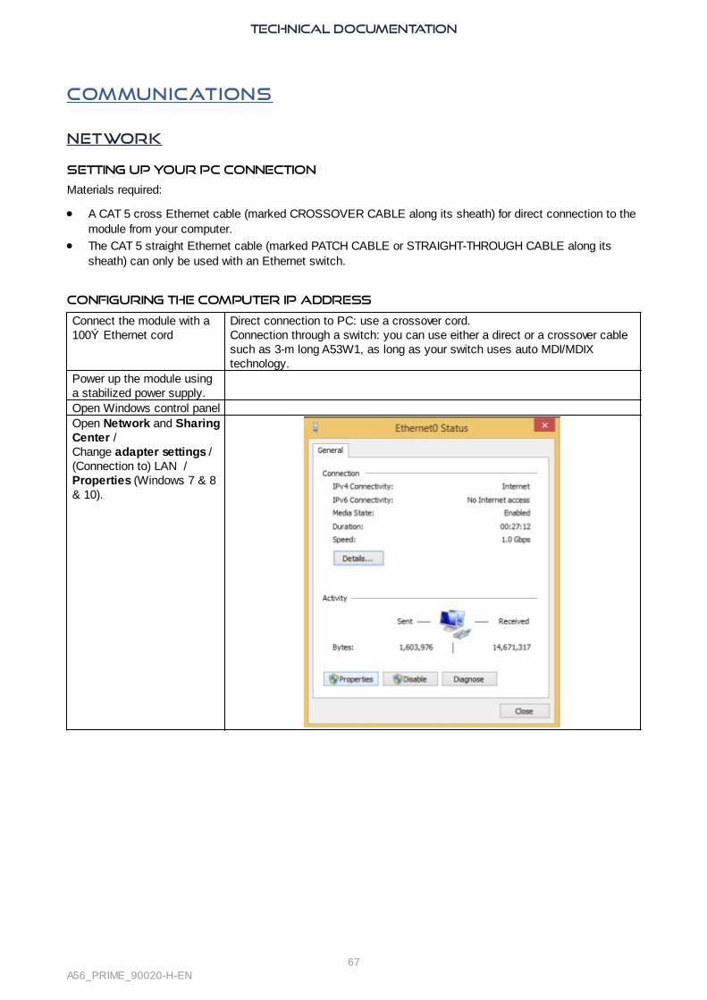
TECHNICAL DOCUMENTATION
67A56_PRIME_90020-H-EN
Communications
Network
Setting up your PC connection
Materials required:
· A CAT 5 cross Ethernet cable (marked CROSSOVER CABLE along its sheath) for direct connection to themodule from your computer.
· The CAT 5 straight Ethernet cable (marked PATCH CABLE or STRAIGHT-THROUGH CABLE along itssheath) can only be used with an Ethernet switch.
Configuring the computer IP address
Connect the module with a100Ω Ethernet cord
Direct connection to PC: use a crossover cord.Connection through a switch: you can use either a direct or a crossover cablesuch as 3-m long A53W1, as long as your switch uses auto MDI/MDIXtechnology.
Power up the module usinga stabilized power supply.Open Windows control panelOpen Network and SharingCenter / Change adapter settings / (Connection to) LAN / Properties (Windows 7 & 8& 10).

TECHNICAL DOCUMENTATION
68A56_PRIME_90020-H-EN
Click on Properties(Windows 7 or 8 or 10).
Change the IP address of the MODULE
Using i4Gen Suite Software (or LCD display), in the System/Network Configuration menu.The module supports DHCP: in this case, the module must be connected to a network equipped with a DHCPserver.On power-up, the module obtains an IP address from the DHCP Server. If the DHCP protocol fails, the fixed IP address of the module is used (Factory setting: 192.168.11.1).
On core module, you can reset the IP address (192.168.11.1) by holding the button on the rear face when themodule is powered.
Note: Contact your network administrator to configure your router and/or the units according to your needs.
Hostname
It is possible to assign a device name to the module in relation to its IP address;You can then use this device name in i4Gen Suite Software to connect to the module.The device name can be change in i4Gen Suite Software/System/Network Configuration menu. Maximum length: 16 characters. In Windows, the last character defines the type of service (0 is the usual value). Allowed characters: reduced ANSI set;"-" and"." are allowed except as first and last characters.

TECHNICAL DOCUMENTATION
69A56_PRIME_90020-H-EN
Modbus TCP/IP
Abilities
The complete list of variables is described in Software variables.Through Ethernet communication where the module acts as a Modbus slave, you can:
· Upload many readings and module internal variables.
· Download values for many module internal variables.
Type Range Fault access rightReadings (measurements, states,..). [0000] … [1999] Read only.Parameters. [2000] … [3999] Read/Write.Modes, statuses, settings,... [4000] … [9999] Read.Readings associated with digital inputs. [4500] … [4649] Write (subject to activation).
Supported functions
In addition, the following functions are supported:· Reading bit-fields, listed in a dedicated tab of the file and organized in 16-bit words. These variables
are listed in Software variables.· Reading contiguous configurable data block.
Those functions allow a significant performance gain and help reducing the load on an Ethernet network.
Configuration
To communicate through Modbus TCP, define the following settings:
· Module IP address set in System/Ethernet.
· Modbus TCP port [3014], generally 502, set in System/Ethernet.
· Modbus TCP rights: see further.
The module handles up to 4 simultaneous connections. This can be used for multiple HMIs for example.For more details on the Ethernet configuration, see Network.
Functions
The module supports the following Modbus functions:
Functions Description01, 02 Read logical data (Coil status, discrete input status).03, 04 Read holding/input registers (16 bit).05 Write logical value (single coil).06 Write single register (16-bit variable).15 (0x0F) Write multiple logical values (multiple coils).16 (0x10) Write multiple registers.
All module variables are 16-bit registers. Yet it might be useful to consider them as logical values (if they areonly set to 0 or 1) to simplify Modbus TCP communication with some external PLC. If function 01 or 02 is usedto read an internal register that is different from 0, then returned value will be 1.The module registers start from address 0. Depending on your Modbus TCP client equipment-software, youmay need to use an offset of 1 when reading/writing registers as addresses may start from address 1. In thiscase, request address/register number 1 to access variable 0000 inside the module.
The 32-bit variables can only be written using 0x10 function.If a digital input modifies a piece of data also to be written by Modbus, the latest request takes over the other.
Data [10000]…[10299] can be read by block (see further).

TECHNICAL DOCUMENTATION
70A56_PRIME_90020-H-EN
Access rights
The access rights depend on the parameter type and on Modbus access permissions. To manage access
rights, set to 1 the corresponding bits in the word [3015]:
Description Bit # Default value
Writing to date/ time 0 0
Writing to Engine counters 1 0
Not used 2 0
Writing to digital input function register 3 1
Not used 4 0
Not used 5 0
Not used 6 0
Not used 7 0
Reading via Modbus TCP 8 1
Writing via Modbus TCP 9 1
Using i4Gen Suite Software/System/Network configuration/Modbus TCP access rights, you can tick check-
boxes to set those:
Bit # Label Use
0 Writing to date/ time Module time synchronization.
1 Writing to Engine counters Manual counter adjustment (see following table).
3 Writing to digital input function registerOpens the possibility to activate a digital input functionusing Modbus TCP.
8 Reading using Modbus TCPOpens the possibility to grant reading individualpermissions.
9 Writing using Modbus TCPOpens the possibility to grant writing individualpermissions.
The counters, encoded on 32 bits, include:
Meters(MSB|LSB)
Label
0080|0079 Generator KWh
0082|0081 Generator KVARh
0084|0083 Engine running hours
BitFields
Bit-fields are meant for decreasing communication bus load. They pack up to 16 logic variables inside a singleregister. This way, a single Modbus TCP request can be used to read a chunk of information. Each variablecontains the current value of 16 logic variables such as breaker positions, faults, alarms…
They are listed out in Software variables.The bit-fields [0956]…[0969] have latched values: a reset is required for them to return to 0.
Note: Available data are related only to faults that occurred after the latest power up sequence. Events thatoccurred before the module has been power cycled are listed in the FAULT pages but not among the variables.

TECHNICAL DOCUMENTATION
71A56_PRIME_90020-H-EN
Modbus communication example
The table below shows a Modbus TCP client sending a reading request (function 04) of 6 registers starting from
variable [0079].
Client request Module server response
Field Value Field Value
Function code 04 Required function. 04
Starting Register (MSB) 00 Data bytes (=2*Nb of registers requested). 6
Starting Register (LSB) 79 Value of register 0079 (MSB). D0
Count of registers (MSB) 00 Value of register 0079 (LSB). D1
Count of registers (LSB) 06 Value of register 0080 (MSB). D2
Value of register 0080 (LSB). D3
Value of register 0081 (MSB). D4
Value of register 0081 (LSB). D5

TECHNICAL DOCUMENTATION
72A56_PRIME_90020-H-EN
CRE-Link®
Presentation
This CAN bus is used as a communication means between units of a single Power plant, featuring:· Active and reactive load sharing.
· Automatic load/unload.
· Static paralleling.
· Dead bus management.
· Segments and Power plant management.
· Other data exchange.Standard CAN bus rules apply here. Refer to CAN bus good practices to connect units properly on CAN bus.
CAN bus ALARMS/faultS
CAN communication between CRE TECHNOLOGY units is continuously checked by each unit on the CANbus. The count of units connected to CAN bus must be the same as the count of units declared inside eachunit. In case of a problem on the bus, alarms or faults can occur:
· Missing product: One or several GENSYS COMPACT PRIME are missing on the CRE-Link®.
· Missing master: One or several MASTER COMPACT/BTB COMPACT/MASTER 1B COMPACT aremissing on CRE-Link®.
· Isolated product: The communication with the other products is lost. Check that the 120Ω terminationresistors are used correctly (see CAN bus good practices). Check that CAN bus cable is properlyconnected.
· Unknown product: An incompatible product is connected on the CAN bus. The module will not startthe Generator.
· Mismatch version: A module with an incompatible version is connected on the CAN bus. The modulewill share the load using droop.
Note: Problems can occur if two or more unit have the same Generator number.
For Missing product, Missing master and Isolated product, you can configure the behavior to be adopted incase of a CAN fault.
If a remote start occurs on a module working in AUTO mode and set up to manage dead bus and Isolatedproduct has already been triggered, the module starts its engine and closes its breaker (if there is no voltageon the Bus-bar) after a delay that depends on the Generator number. If there is voltage on the Bus-bar, themodule synchronizes the Generator before connecting to the Bus-bar. See Control on dead bus managementin Synchronization.
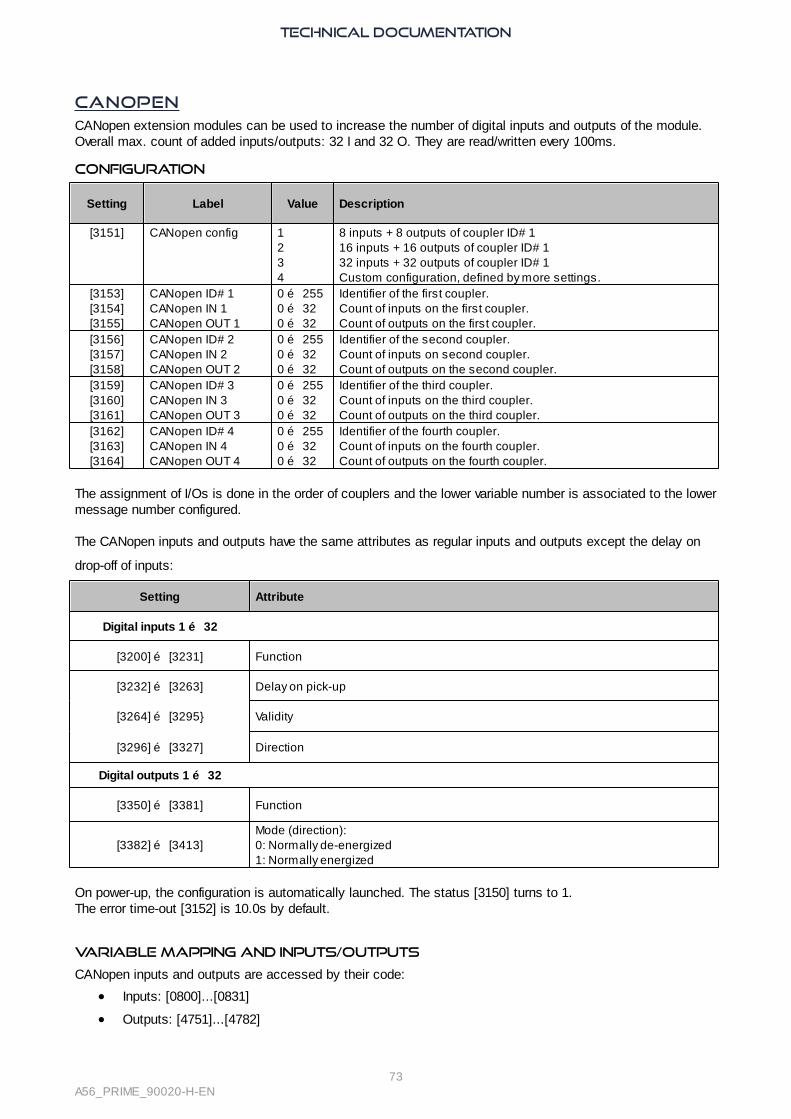
TECHNICAL DOCUMENTATION
73A56_PRIME_90020-H-EN
CANopenCANopen extension modules can be used to increase the number of digital inputs and outputs of the module.Overall max. count of added inputs/outputs: 32 I and 32 O. They are read/written every 100ms.
Configuration
Setting Label Value Description
[3151] CANopen config 1234
8 inputs + 8 outputs of coupler ID# 1 16 inputs + 16 outputs of coupler ID# 132 inputs + 32 outputs of coupler ID# 1Custom configuration, defined by more settings.
[3153][3154][3155]
CANopen ID# 1CANopen IN 1CANopen OUT 1
0 … 2550 … 320 … 32
Identifier of the first coupler.Count of inputs on the first coupler.Count of outputs on the first coupler.
[3156][3157][3158]
CANopen ID# 2CANopen IN 2CANopen OUT 2
0 … 2550 … 320 … 32
Identifier of the second coupler.Count of inputs on second coupler.Count of outputs on the second coupler.
[3159][3160][3161]
CANopen ID# 3CANopen IN 3CANopen OUT 3
0 … 2550 … 320 … 32
Identifier of the third coupler.Count of inputs on the third coupler.Count of outputs on the third coupler.
[3162][3163][3164]
CANopen ID# 4CANopen IN 4CANopen OUT 4
0 … 2550 … 320 … 32
Identifier of the fourth coupler.Count of inputs on the fourth coupler.Count of outputs on the fourth coupler.
The assignment of I/Os is done in the order of couplers and the lower variable number is associated to the lowermessage number configured.
The CANopen inputs and outputs have the same attributes as regular inputs and outputs except the delay on
drop-off of inputs:
Setting Attribute
Digital inputs 1 … 32
[3200] … [3231] Function
[3232] … [3263] Delay on pick-up
[3264] … [3295 Validity
[3296] … [3327] Direction
Digital outputs 1 … 32
[3350] … [3381] Function
[3382] … [3413]Mode (direction):0: Normally de-energized1: Normally energized
On power-up, the configuration is automatically launched. The status [3150] turns to 1.The error time-out [3152] is 10.0s by default.
Variable mapping and inputs/outputs
CANopen inputs and outputs are accessed by their code:
· Inputs: [0800]...[0831]
· Outputs: [4751]...[4782]
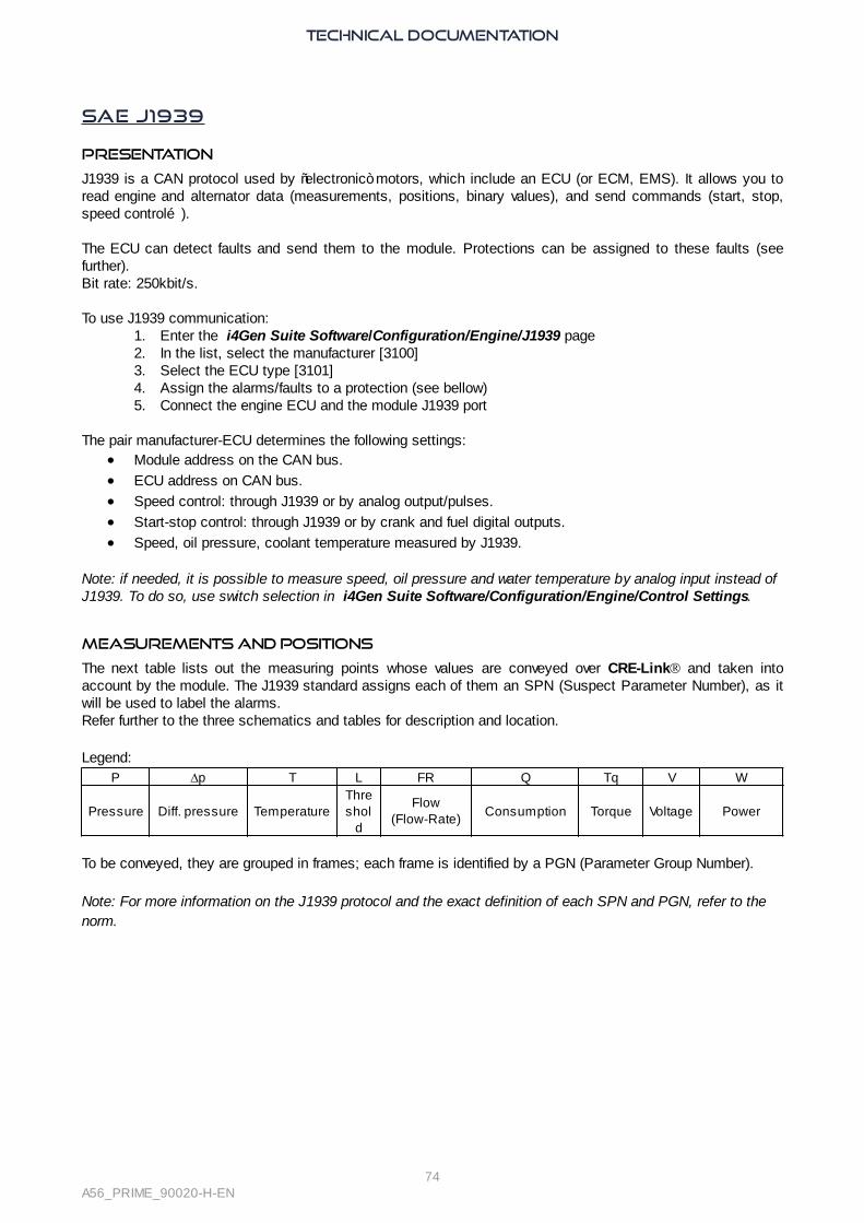
TECHNICAL DOCUMENTATION
74A56_PRIME_90020-H-EN
SAE J1939
Presentation
J1939 is a CAN protocol used by “electronic” motors, which include an ECU (or ECM, EMS). It allows you toread engine and alternator data (measurements, positions, binary values), and send commands (start, stop,speed control…).
The ECU can detect faults and send them to the module. Protections can be assigned to these faults (seefurther). Bit rate: 250kbit/s.
To use J1939 communication:1. Enter the i4Gen Suite Software/Configuration/Engine/J1939 page2. In the list, select the manufacturer [3100]3. Select the ECU type [3101]4. Assign the alarms/faults to a protection (see bellow)5. Connect the engine ECU and the module J1939 port
The pair manufacturer-ECU determines the following settings:· Module address on the CAN bus.
· ECU address on CAN bus.
· Speed control: through J1939 or by analog output/pulses.
· Start-stop control: through J1939 or by crank and fuel digital outputs.
· Speed, oil pressure, coolant temperature measured by J1939.
Note: if needed, it is possible to measure speed, oil pressure and water temperature by analog input instead ofJ1939. To do so, use switch selection in i4Gen Suite Software/Configuration/Engine/Control Settings.
Measurements and positions
The next table lists out the measuring points whose values are conveyed over CRE-LinkÒ and taken intoaccount by the module. The J1939 standard assigns each of them an SPN (Suspect Parameter Number), as itwill be used to label the alarms. Refer further to the three schematics and tables for description and location.
Legend:P Dp T L FR Q Tq V W
Pressure Diff. pressure TemperatureThreshol
d
Flow(Flow-Rate)
Consumption Torque Voltage Power
To be conveyed, they are grouped in frames; each frame is identified by a PGN (Parameter Group Number).
Note: For more information on the J1939 protocol and the exact definition of each SPN and PGN, refer to thenorm.

TECHNICAL DOCUMENTATION
75A56_PRIME_90020-H-EN
Fuel circuit and ECU
SPN Description PGN
91 Accelerator pedal position 1 (run in %). F003
1242 Instantaneous estimated brake power. FE92512 Driver's demand engine - Percent torque related to maximum engine torque. F004515 Engine's desired operating speed. Indication of optimal speed for the current conditions. May include the
torque generated to accommodate power demands and exclude dynamic commands from smoke/shift.FED
F
2432 Engine demand - percent torque. F004190 Engine speed. F004188 Engine idle speed. FEE3189 Engine rated speed (max. rotational velocity of engine crankshaft under full load conditions). FEB
E166 Engine rated power (net brake power at rated speed). FEB
E1013 Trip maximum engine speed since latest trip reset. FEB7171 Ambient air temperature. FEF5182 Engine trip fuel (fuel consumed during all or part of a run). FEE9250 Engine total fuel used. FEE9183 Engine fuel rate. FEF2184 Engine instantaneous fuel economy (covered distance/fuel consumption). FEF294 Engine fuel delivery pressure (as delivered by supply pump to high pressure pump). FEEF97 Water in fuel indicator (binary signal). FEFF
157 Engine injector metering rail 1 pressure. FEDB
174 Engine fuel temperature 1 (at injector inlet). FEEE
168 Battery potential /Power input1. FEF7
158 Key switch supply potential (alternative to 168). FEF7
1136 ECU temperature. FEA4

TECHNICAL DOCUMENTATION
76A56_PRIME_90020-H-EN
108 Barometric pressure. FEF5
1387 Pressure auxiliary sensor #1 FE8C
1388 Pressure auxiliary sensor #2 FE8C
247 Engine total hours of operation. FEE5

TECHNICAL DOCUMENTATION
77A56_PRIME_90020-H-EN
Air, exhaust and alternator
SPN Description PGN107 Air inlet filter #1 differential pressure (first or sole filter). FEF652 Inter-cooler temperature. FEE
E106 Air inlet pressure (at inlet to intake manifold or air box). FEF6102 Intake manifold #1 pressure (boost pressure measured downstream of turbo compressor). FEF63563 Intake manifold #1 absolute pressure. FDD
0105 Intake manifold #1 temperature. FEF6172 Air inlet temperature. FEF522 Extended crankcase blow-by pressure (differential pressure across a venturi). FEEF
101 Crankcase pressure. FEEF1039 Trip Fuel (gaseous) (fuel consumed during all or part of a run). FEAF1040 Total Fuel used (gaseous) over the engine life. FEAF1390 Fuel valve 1 inlet absolute pressure. FE8B2433 Exhaust gas temperature - Right manifold. FE072434 Exhaust gas temperature - Left manifold. FE07173 Exhaust gas temperature (alternative to 2433 + 2434). FEF6176 Turbocharger oil temperature. FEE
E81 Diesel particulate filter (trap) inlet pressure. FEF692 Engine percent load at current speed.
The ratio of actual engine percent torque (indicated) to maximum indicated torque available at the currentengine speed, clipped to zero torque during engine braking .
F004
513 Actual percent torque.The calculated output torque of the engine. The data is transmitted in indicated torque as a percent ofreference engine torque. The engine percent torque value is not negative and includes the torquedeveloped in the cylinders required to overcome friction.
F004
514 Nominal friction (percent of reference torque). Torque that compensates the engine and pumps losses. FEDF
1124 Alternator winding 1 temperature. FEA7

TECHNICAL DOCUMENTATION
78A56_PRIME_90020-H-EN
1125 Alternator winding 2 temperature. FEA71126 Alternator winding 3 temperature. FEA7
Oil and coolant circuits
SPN Description PGN98 Oil level (ratio of sump current volume to required volume). FEEF99 Oil filter differential pressure. FEF
C100 Oil pressure. FEEF175 Oil temperature 1. FEE
E1208 Oil pressure (upstream the pre-filter). FE92109 Coolant pressure. FEEF110 Coolant temperature FEE
E111 Coolant level (ratio of current volume to total volume). FEEF112 Coolant filter differential pressure. FEF6
These measurements are shown in i4Gen Suite Software/Scada/Engine meters. A measurement not sent bythe ECU is shown as “…”:
Note: To get the measurements through Modbus TCP, refer to Modbus TCP/IP.

TECHNICAL DOCUMENTATION
79A56_PRIME_90020-H-EN
faults
The module can monitor diagnostic messages (DM1) from the ECU. Only relevant diagnostic messages aretaken into account and used in the module fault/alarm system. The module can understand and interpretmessages for display, process, and protection.
When you activate the internal module RESET ([SHIFT+INFO] button or remote reset), the module sends areset message (DM3) to the ECU. If the diagnostic message is not sent by the ECU for more than 3s, thecorresponding fault/alarm is automatically reset to Off.
Each of the following J1939 messages/alarms can be configured to trigger one of the module protections:
J1939 messageControl in i4Gen Suite
SoftwareMessage description (ECU internal threshold)
High speed [3104] CT speed + Engine speed above least severe high threshold.
Very high speed [3105] CT speed ++ Engine speed above the most severe high threshold.
High water temperature [3106] CT Cool Temp. + Coolant temperature above least severe high threshold.
Very high water temperature [3107] CT Cool Temp ++ Coolant temperature above the most severe high threshold.
Low oil pressure [3108 CT Oil Press - Oil pressure below least severe low threshold.
Very low oil pressure 3109 CT Oil Press -- Oil pressure below the most severe low threshold.
Malfunction "lamp" 3110 CT Malfunction Message in presence of an emission-related trouble
Protection "lamp" 3111 CT ProtectionTrouble is most probably not electronic subsystem related.E.g., coolant temp. may exceed temp. range.
Amber "lamp" 3112 CT Amber Trouble where the engine need not immediate stop.
Red "lamp" 3113 CT Red Severe enough trouble for the engine to stop.
All thresholds are those set in the ECU. In addition of these known diagnostic messages, the module showsthe latest five unmanaged SPN (what is wrong)/FMI (Failure Mode Identifier, i.e. error type) combinations it hasreceived with the diagnostic message (DM1). These SPN/FMIs are backed up in registers:
Register Description
066406650666
J1939 SPN LO 1 J1939 SPNHI 1 J1939 FMI 1
Latest NSP/IMF received by the module.
066706680669
J1939 SPN LO 2 J1939 SPNHI 2 J1939 FMI 2
Second latest NSP/IMF received by the module.
06700671 0672
J1939 SPN LO 3 J1939 SPNHI 3 J1939 FMI 3
Third latest NPS/IMF received by the module.
067306740675
J1939 SPN LO 4 J1939 SPNHI 4 J1939 FMI 4
Fourth latest NPS/IMF received by the module.
0676 0677 0678
J1939 SPN LO 5 J1939 SPNHI 5 J1939 FMI 5
Fifth latest NPS/IMF received by the module.
SPN LO corresponds to LSB, SPN HI to MSB
Note: In any case, a fault/alarm is activated on reception of an unknown SPN/FMI if the Red [3113]/ Amber[3112] control has been set. It is deactivated by Reset.

TECHNICAL DOCUMENTATION
80A56_PRIME_90020-H-EN
Controls
SPN
Description Details PGN
898
Requested speed Engine speed which the engine is expected tooperate at if the speed control mode is active. 0
970
Start-Stop Engine shutdown switch. F001
2881
Frequency selection Ability to switch the rated speed. Switched on astate transition while engine speed is 0. 50/60Hz(CM570 and PGI) or sources given through anibble (e.g. see ECU8 section in Appendices/ECUJ1939/MTU).
FDCB

TECHNICAL DOCUMENTATION
81A56_PRIME_90020-H-EN
CAN bus Good PracticesThis chapter describes rules to be used to ensure reliable CAN communication. These rules must be applied toall CAN communications, including CRE-Link® and ECU/remote I/O CAN bus.CRE TECHNOLOGY recommends to always use a shielded cable to connect CAN bus.
CABLES
WARNINGRISK OF EQUIPMENT DAMAGESwitch off the unit before plugging or unplugging the CAN bus connector or disconnecting the wires.Failure to follow this instruction can damage the CAN transmitter/receiver.
Cables used must be selected to respond to CAN bus specificities. Always use shielded twisted wire pairs.Deploy the CAN bus (no mesh, ring or star topology) as shown below:
Bus Mesh Ring Star
Both ends of the CAN bus must be terminated with a 120Ω resistor. The module has a 120Ω resistor for thispurpose. Wiring the terminal RES to CAN H will link CAN L and CAN H with a resistor.The next figure gives the example of three units connected through a CAN bus. Do NOT install any resistor norlink the terminal RES and CAN H together in the middle unit.
WARNINGRISK OF EQUIPMENT DAMAGEDo not, in any cases, connect 0V pin to - power supply pin.Failure to follow this instruction may damage the CAN transmitter/receiver and the controller itself.

TECHNICAL DOCUMENTATION
82A56_PRIME_90020-H-EN
CRE TECHNOLOGY provides a complete range of products aimed at installing your CAN bus (cords,wires, connectors…). Please contact your local CRE TECHNOLOGY distributor to help you to choose equipment that fitsyour needs.
MAXIMUM LENGTH & BIT RATE
The maximal length of a CAN bus depends mostly on the communication speed, but also on the quality ofwires and connectors used.
The following table shows the maximal length of a CAN bus depending on the bit rate:
Bit rate (Kbits/s) 10 20 50 125 250 500 800
Maximal length (m) 5000 2500 1000 500 250 100 50
The next table lists the standard bit rate of each CAN protocol that can be used by a CRE TECHNOLOGY unit:
Bus ProtocolBit rate(Kbits/s)
Note
CAN1 CRE-Link® 125 Fixed.
CAN2
CANopen 125 (default)Can be selected between 125/250/500/1000kbit/s (By i4Gen Suite Software or modification by variablenumber).
J1939 250 (default)Switch automatically to the right speed when selectingan ECU type.

TECHNICAL DOCUMENTATION
83A56_PRIME_90020-H-EN
Website
Access
Menu treesDuring navigation on the PC, press the ESC button to return to the parent menu of the page displayed in thebrowser.
Access to the website1. Connect a PC to the module via an Ethernet connector.2. Use a web browser such as Firefox or Internet Explorer for example.3. Enter the IP address (factory setting: http://192.168.11.1), or the module Hostname.4. Enter the module password when the Password page appears (see chapter Password).
Core moduleFor modules without display, it is not possible to connect to the product if the IP address of the product isunknown.In this case, it is therefore possible to reset the IP address to its default value (192.168.11.1) by doing thefollowing :
· Switch off the product by removing the power supply
· Press the button dedicated to this function: Button located at the bottom left on the back of the product(side without screen printing)
· Power the product while holding the button
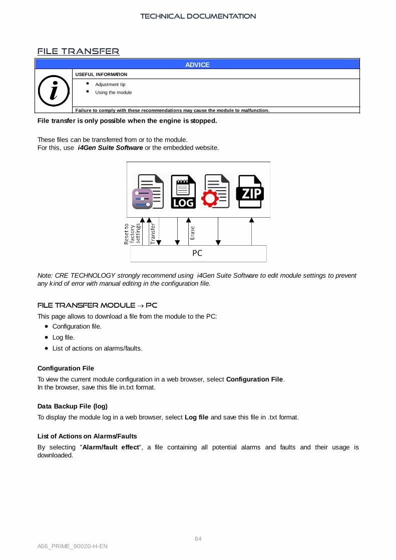
TECHNICAL DOCUMENTATION
84A56_PRIME_90020-H-EN
File Transfer
ADVICEUSEFUL INFORMATION
§ Adjustment tip
§ Using the module
Failure to comply with these recommendations may cause the module to malfunction.
File transfer is only possible when the engine is stopped.
These files can be transferred from or to the module.For this, use i4Gen Suite Software or the embedded website.
Note: CRE TECHNOLOGY strongly recommend using i4Gen Suite Software to edit module settings to preventany kind of error with manual editing in the configuration file.
File transfer MODULE ® PC
This page allows to download a file from the module to the PC:
· Configuration file.
· Log file.
· List of actions on alarms/faults.
Configuration File
To view the current module configuration in a web browser, select Configuration File. In the browser, save this file in.txt format.
Data Backup File (log)
To display the module log in a web browser, select Log file and save this file in .txt format.
List of Actions on Alarms/Faults
By selecting "Alarm/fault effect", a file containing all potential alarms and faults and their usage isdownloaded.

TECHNICAL DOCUMENTATION
85A56_PRIME_90020-H-EN
Example:
S/N:0114A0001Type:A56Z0Version:v1.00Bootversion:v1.00Date:28/06/15Hour:12h25m21s
***** Alarm/fault effect *****
0 : Desactive1 : Defaut Gen electrique2 : Defaut Bus electrique3 : Alarme4 : Defaut non critique5 : Defaut critique6 : Help+Defaut non crit7 : Help+Defaut Gen.Elec8 : Statisme
Potentiel Alarm./Def. Parametre actuel ANSI C37-2V00600 Etat CAN1 <-- V03052 = 8V00602 CAN2 etat <-- V03053 = 0V04200 Survitesse <-- V02352 = 3 12V04201 Sous vitesse <-- V02355 = 0 14……
file transfer PC ® MODULE
This page allows you to send a configuration file, or a language file.When the transfer operation is complete, the transfer result is displayed on the screen.
Note:
· Before making a change to the module configuration, it is recommended to save the current configuration.File transfer is only possible when the Generator is stopped (The module must be in the "Waiting" powerstate).
· Reset to factory settings must be done using i4Gen Suite Software (password level 2 mandatory).

TECHNICAL DOCUMENTATION
86A56_PRIME_90020-H-EN
Firmware Update
Prerequisites
1. Upgrading software is done via an Ethernet connection. It is mandatory to have a PC connected tothe module (Use an Ethernet cable from module to PC without using LAN).
2. Stop the Generator (The module must be in the Waiting power state).
3. Save the current configuration as a text file. Otherwise the default settings will be enforced (exceptfor the Ethernet settings).
4. Disconnect all terminals, except the power supply and Ethernet connections.
Note: Be sure there is no Modbus request on the module during upgrading.
Start upgrade
1. Connect to i4Gen Suite Software/System/PC transmit/receive or to module website.2. Select Update firmware and browse the archive.3. Click on the Update button.4. Alarm/fault LEDs blink and state is displayed on LCD screen.5. Wait until Update firmware successful shows.6. If needed, restore the settings from the text file previously saved.
Note: The module will restart during the update process. Please wait for the "Update firmware successful"message before starting to use the module (about 2 minutes).

TECHNICAL DOCUMENTATION
87A56_PRIME_90020-H-EN
Appendices
ECU J1939
CATERPILLAR
Manufacturer[3100]
ECU [3101] Air + Exhaust + Alternator Oil and coolant
[8] GENERIC [0]
A4E2 (C4.4 C6.6)[1] 91 515 250 157 183 168 158 247 102 105 106 172 92 513
ECU [3101] Speed Start/Stop Speed selectionGENERIC [0] x - -ADEM A4E2 (C4.4 & C6.6) [1] x - -
CUMMINS

TECHNICAL DOCUMENTATION
88A56_PRIME_90020-H-EN
Manufacturer[3100]
ECU [3101] Fuel & ECUAir + Exhaust +
AlternatorOil and coolant
(1)
[6]
GENERIC [0]
QSX15G8(CM570)[1]
157 175 183 168 108 102 105 513
CM850 [2]
QSB5 (PGI 1.1) [3] 91a 1242b 512a 515a 2432b
157b
174a 182-3-4a 247-50 168108 97
102 105 92a 513514a
100 1208b 110 111bQSB7 (PGI 1.1) [4]
QSL9 (PGI 1.1) [5]Id+ 512b515b 184b94b
174b1136bId + 92b 101b 173b
514b Id + 175b 109b
QSM11 (PGI 1.1) [6]91a 1242b 512a 515a 2432b
175 182 250 183 168 108 97b
247
102 105 92a 513514a
100 1208b 110 111b
QSX15 [7] 91a 512a 515a 175 182a 250a
183 168 108 247a 102 105 92a 513a
514a 100 110
QSK19 (PGI 1.1) [8]91a 1242b 512a 515a 2432b 94
97b 157b174b182b-3-4a247-50b168 108
102 105 101 92a 513514a 22a
100 1208b 110111b109
QSK38 (PGI 1.1) [9] 91a 1242b 512a 515a 2432b
157b 174 175b 94 182b 250b
183 184a 168 108 97b
102 105 101 513514a 22a 92a
100 1208b 110 111b109
QSK50 (PGI 1.1) [10]QSK60 (PGI 1.1) [11]
1. ECU Cummins can contain different firmwares depending on their source:a) Industrial model onlyb) G Drive only
2. Cummins 109G ECU may not support J1939 speed control. ECU with Cummins G Drive firmware should support J1939speed control.
ECU [3101] Speed Start/Stop Speed selection
GENERIC [0] x x x
QSX15-G8 (CMS570) [1] x x x
CM850 [2] x - x
QSB5 (PGI 1.1) [3] x - x
QSB7 (PGI 1.1) [4] x - x
QSL9 (PGI 1.1) [5] x - x
QSM11 (PGI 1.1) [6] x - x
QSX15 (CMS570) [7] x x x
QSK19 (PGI 1.1) [8] x - x
QSK38 (PGI 1.1) [9] x - x
QSK50 (PGI 1.1) [10] x - x
QSK60 (PGI 1.1) [11] x - x
DETROIT DIESEL

TECHNICAL DOCUMENTATION
89A56_PRIME_90020-H-EN
Manufacturer[3100]
ECU [3101] Fuel and ECUAir + Exhaust +
AlternatorOil and coolant
[11]
GENERIC [0]
DDEC III [1]
DDEC IV [2]91 512-5 188-9 174 94 157 171
182 247-50 183-4 166-8108 158 52 102 22 101 105
106 172 107 173 17692 513 514
98 99 100 175109 110 111 112
DDEC X [3]
91 512 2432 188 189 166 174 94 97 157 171 182250 183 18 168 1136
108 158 247
ECU [3101] Speed Start/Stop Change speed
GENERIC [0] - - -
DDEC III [1] - - -
DDEC IV [2] - - -
DDEC X [3] - - -
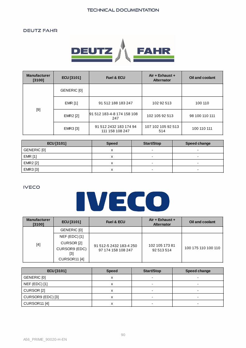
TECHNICAL DOCUMENTATION
90A56_PRIME_90020-H-EN
DEUTZ FAHR
Manufacturer[3100]
ECU [3101] Fuel & ECUAir + Exhaust +
AlternatorOil and coolant
[9]
GENERIC [0]
EMR [1] 91 512 188 183 247 102 92 513 100 110
EMR2 [2] 91 512 183-4-8 174 158 108247
102 105 92 513 98 100 110 111
EMR3 [3] 91 512 2432 183 174 94111 158 108 247
107 102 105 92 513514
100 110 111
ECU [3101] Speed Start/Stop Speed change
GENERIC [0] x - -
EMR [1] x - -
EMR2 [2] x - -
EMR3 [3] x - -
IVECO
Manufacturer[3100]
ECU [3101] Fuel & ECUAir + Exhaust +
AlternatorOil and coolant
[4]
GENERIC [0]
NEF (EDC) [1]
91 512-5 2432 183-4 25097 174 158 108 247
102 105 173 8192 513 514
100 175 110 100 110CURSOR [2]
CURSOR9 (EDC)[3]
CURSOR11 [4]
ECU [3101] Speed Start/Stop Speed change
GENERIC [0] x - -
NEF (EDC) [1] x - -
CURSOR [2] x - -
CURSOR9 (EDC) [3] x - -
CURSOR11 [4] x - -

TECHNICAL DOCUMENTATION
91A56_PRIME_90020-H-EN
JOHN DEERE
Manufacturer[3100]
ECU [3101] Fuel & ECUAir + Exhaust +
AlternatorOil and coolant
[7]
GENERIC [0]
JDEC [1]91 512 515 2432
182 250 183 184 94 157174 158 247
10752 106 102 105 101173 176 81 92 513
514
98 100 175109 110 111 112
ECU [3101] Speed Start/Stop Speed change
GENERIC [0] x - -
JDEC [1] x - -
MTU
Manufacturer[3100]
ECU [3101] Fuel & ECUAir + Exhaust +
AlternatorOil and coolant
[10]
Voir AppendiceMTU
GENERIC [0]
ADEC-2000 [1] 94 158 247 171 174 188189 166 1136 1387 1388
247
52 102 2433 24341124-5-6
100 110 175ADEC-4000 [2]
ECU8 Smartconn[3]
515 94 158-66 182-3-8-9 247-50 1136
105 3563 100 109 110
ECU8 + SAM [4]
ECU [3101] Speed Start/Stop Speed adjustment
GENERIC [0] - x x
ADEC-2000 [1] - x x
ADEC-4000 [2] - x x
ECU8 + Smart Connect [3] x x x
ECU8 + SAM [4] - x x

TECHNICAL DOCUMENTATION
92A56_PRIME_90020-H-EN
ADEC
The SAM (Service and Automation module) is associated with the ADEC 2000 or ADEC 4000. The set isreferred to as the ECU7.Disconnect X13 to turn off the power. Insert the CCB2 card into SAM slot #3.The ADEC ECU, SAM and the module communicate via 2 CAN buses: a CAN bus between the SAM and theADEC with a proprietary protocol, a CAN bus between the module and the SAM with the J1939 protocol. TheSAM includes a termination resistor.
The ADEC controls, among other things, the engine speed.
Typical ADEC and SAM connection:
Signal ADEC X1 Cabinet SAM X23 connecteur
CAN High 33 X7-2 2
CAN Low 18 X7-1 1
CAN ground 34 X7-3 3
Speed out + X2-
Speed out – X2-

TECHNICAL DOCUMENTATION
93A56_PRIME_90020-H-EN
ECU8
Smart Connect is used for:· select the origin of the speed control via an 8 position selector
· set droop frequency and slope
Via the K1 connection box, the ECU8, the Smart Connect and the module are connected: a CAN bus betweenthe Smart Connect and the ECU8 with a proprietary protocol, a CAN bus between the Smart Connect and themodule with the J1939 protocol. X4 is the connector supporting the J1939 to connect to the module.

TECHNICAL DOCUMENTATION
94A56_PRIME_90020-H-EN

TECHNICAL DOCUMENTATION
95A56_PRIME_90020-H-EN
PERKINS
Manufacturer[3100]
ECU [3101] Fuel & ECUAir + Exhaust +
AlternatorOil and coolant
[3]GENERIC [0]
1100 A4E 91 515 188 174 250 183
247102 105 92 513 100 110
ECU [3101] Speed Start/Stop Speed change
GENERIC [0] x - -
1100 (A4E) x - -
SCANIA
Manufacturer [3100] ECU [3101] Fuel & ECUAir + Exhaust +
AlternatorOil and coolant
GENERIC [0]
S6 (DC16-45A) [1]91 512 188 183 184
247102 105 92 513 514 100 110 111
ECU [3101] Speed Start/Stop Speed selection
GENERIC [0] x x -
S6 (DC16-45A) [1] x x -

TECHNICAL DOCUMENTATION
96A56_PRIME_90020-H-EN
VOLVO PENTA
Manufacturer [3100]
ECU [3101] Fuel & ECUAir + Exhaust +
AlternatorOil and coolant
[2] GENERIC [0]
EMS2 [1] 94 182 250 247 102 172 100 175 110
EDC4 [2] Same as Deutz EMR2 Same as Deutz EMR2Same as Deutz
EMR2
94xGE [3] 91 512 188 1013 182 94 250 183 97 158 247
102 105 92 513 100 175 110 111124xGE [4]
1640-2GE [5] 91 512 188 1013 18294 250 183 158 247
102 105 92 513 100 175 110 111
1643GE [6] 91 512 188 1013 18294 250 183 158 247
102 106 107 173 92 513514
100 175 110 111
D6 [7] 91 512 188 1013 182 94 250 183 97 158 247
102 105 92 513 100 110 111D7 [8]
D13GE-Tier3 [9] 91 512 188 1013 18294 250 183 97 158 247
102 105 92 513 100 175 110 111
ECU [3101] Speed Start/Stop Speed change
GENERIC [0] x - -
EMS2 [1] x x x (Multi-speed engine)
EDC4 [2] x - -
94xGE [3] x x x
124xGE [4] x x -
1640-2GE [5] x x x
1643GE [6] x x x
D6 [7] x x -
D7 [8] x x -
D13GE-Tier3 [9] x x x

TECHNICAL DOCUMENTATION
97A56_PRIME_90020-H-EN
Short Circuit ProtectionThe tripping time depends on the duration an alternator winding can endure an over current.A IDMT (Inverse Definite Minimum Time) curve is defined by:
· a type (IEEE, IEC, IAC),
· Is: current for infinite time in type 1 (asymptote value); type 1.2 is not used,
· T: tripping time for I= 10 x Is.
Definition of TMS (Time Multiplier Setting); by default, [2475] = 1:
T is the tripping time for I/Is = 10 (Is= set point, akathreshold)
TMS = 1 corresponds to T= 1.5 s at I = 10 xIs
Note: In brief, the higher the over-current, the faster the trip.
IEC CURVES
Characteristics k a (defined the type A, B,C)
Selection in i4Gen SuiteSoftware
b
(Standard) inverse / A 0.14 0.02 Preset 2.97Very inverse / B 13.5 1 Preset 1.5Long time inverse / B 120 1 Custom 13.33Extremely inverse / C 80 2 Preset 0.808Ultra inverse 315.2 2.5 Custom
The time for T curves must be divided by β to get the time for TMS curves.

TECHNICAL DOCUMENTATION
98A56_PRIME_90020-H-EN
T curves with t=1 for I/Is=10:

TECHNICAL DOCUMENTATION
99A56_PRIME_90020-H-EN

TECHNICAL DOCUMENTATION
100A56_PRIME_90020-H-EN
Inverse curves just above the pick-up value (not logarithmic abscissae I/Is) for various value of TMS:

TECHNICAL DOCUMENTATION
101A56_PRIME_90020-H-EN

TECHNICAL DOCUMENTATION
102A56_PRIME_90020-H-EN
IEEE CURVES
Characteristic curve k c a
Moderately inverse 0.515 0.1140 0.02
Very inverse 19.61 0.491 2
Extremely inverse 28.2 0.1217 2

TECHNICAL DOCUMENTATION
103A56_PRIME_90020-H-EN
HOW TO DERIVE A CURVE BY PARALLELISM
Say a curve is known. We know tsA (s stands for the start curve) for IA/Is (s stands for set point).Two curves with same k, a and c are parallel: K= tsA/Ts10 = tA/T. This can be used to find tA.
In the preceding curves in logarithmic plot, Ts10=1. For a given I/Is (first column of next table), find K in the row.Then ta = K x T.

TECHNICAL DOCUMENTATION
104A56_PRIME_90020-H-EN
I/Is SIT IEC/AVIT, LTIIEC/B
EITIEC/C
UITRI
not av.
IEEE MIIEC/D
IEEE VIIEC/E
IEEE EIIEC/F
1) Means only valid for IEC curves

TECHNICAL DOCUMENTATION
105A56_PRIME_90020-H-EN
TroubleshootingTo get a history of alarms-faults, stop the Generator, connect to i4Gen Suite Software/System/PCtransmit/receive/Download log file from module, and click Download.
To restore factory settings into i4Gen Suite Software, navigate to i4Gen Suite Software/System/PCtransmit/receive/Reset factory settings, and click Reset.
Message "Sensor lost" fault on startIn Configuration/Engine/Control settings, check that the speed measurement origin is accurate (Speedmeasure = magnetic or alternator or J1939).If it originates in the alternator, check the voltage presence on terminals Gen L1, L2, L3, N.If it originates in a magnetic pick-up, check that the engine speed increases up to 1500rpm.If the speed does not reach this value on time (the engine stops), increase the "sensor lost" time-out [4203](default value 5.0s). This time-out is set in i4Gen Suite Software/Configuration/Time-out and delays.
Message "Oil pressure" fault on startCheck the related connections.Check the related settings: mainly, delays and directions of digital/analog inputs.
Message "Isolated product"Check the related connections, including the one of internal resistor (jumper).Check the related settings: count of generators, number of each Generator.
Message "Missing product"Check the other products. One of them is not supplied or disconnected.
Message "Missing master"Check the MASTER COMPACT/MASTER 1B COMPACT/BTB COMPACT products. One of them is notsupplied or disconnected.
Message "Unknown product"Check the other products. One of them is not compatible.
Message "Mismatch version"Check the other products. One of them uses a version which is not compatible.
No J1939 communication Check that the ECU is powered.Check that the configuration correspond to the engine/ECU.Check that the wiring is correct.Power cycle module and ECU. Check that the ECU and its settings are consistent with the J1939 standard.Note: Some ECUs do not provide information if the engine is stopped. Try starting the engine.
Message "Breaker" fault Check the type of breaker against the selection in i4Gen Suite Software/Configuration/Outputs.Stop the other generators.Make sure the digital input Gen breaker feedback is connected.
Start the generators in MAN mode (or just press ). Make sure the breaker LED turns on (green);
otherwise, increase the "breaker feedback" time-out [2304] (default value 5.0s).
The engine starts but runs above/below nominal speed.Check the wiring.Check the fuel supply.Check the speed output.
Cannot connect with PCConsider deactivating the firewall and adding an Anti-virus exception.Check the network wiring, see Network.

TECHNICAL DOCUMENTATION
106A56_PRIME_90020-H-EN
Error Messages When Transferring a File to the Module
Note: "…" indicate a variable number, a label number or a text number according the error message. It will helpyou to locate your error in your configuration file.
ERROR 001: Only when GENSET is STOP
File transfer between computer and the unit should be done only when all conditions below are met i.e. whenengine is stopped.
ERROR 002: Unknown file type
The file type sent is unknown. Check the selected file.
ERROR 004: Write data or checksum error
ERROR 008: Update failed. Please restart update.
Writing memory error during update process. Restart module update.
ERROR 011: No write right on variable ….
Access to this variable is not allowed. Only parameter can be modified.
ERROR 012: No write right on label ….
Access to this label is not allowed. Check your configuration file.
ERROR 013: Text …. doesn't exist.
Access to this text is not possible because it does not exist. Check compatibility of the version/type of the moduleand the configuration file.
ERROR 014: No write right on …. Unit
Access to this unit is not allowed. Check your configuration file.
ERROR 015: Need password 2 to write on …. Variable
Actual password is not sufficient to access such configuration/control level.
ERROR 017: Configuration not allowing …. variable value
The actual setting of the module does not allow modifying this parameter with this value. Check your configurationfile and the value of the parameter before sending again your configuration file.
ERROR 018: Variable …. out of range
The value of the parameter is out of range. Check your configuration file before sending again.
ERROR 019: Wrong value for …. variable
An unexpected value has been detected on this parameter. Check the value of the parameter before sending again.
Ex: a text character has been detected instead of a number.
ERROR 020: Unknown language file
The language file sent does not correspond to a language file for the module. Check the selected language file.
ERROR 021: Too many languages already downloaded
The maximum number of language supported by the module has been reached.
ERROR 022: Wrong language file version

TECHNICAL DOCUMENTATION
107A56_PRIME_90020-H-EN
The language file version is above the module version. Upgrade your module with the latest version available orcatch the language file compatible with your module version.
ERROR 023: Label …. does not exist.
Modifying this label is not allowed. Check the label number before sending the configuration file again.
ERROR 024: Unit …. does not exist.
Modifying this unit is not allowed. Check the unit number before sending the configuration file again.
ERROR 025: Wrong accuracy value on …. (0,1,2 or 3)
The value of the accuracy is out of range. The value must be between 0 and 3.
ERROR 026: Wrong unit value on …. (from 0 to xxx)
The value of the unit is out of range. The value must be between 0 and xxx.
ERROR 027: No header in language file
No header or wrong header of the language file. Check the selected language file before send it again.
ERROR 028: No filename found or too long
No filename or filename is too long. The maximum size of a filename is 40 characters. Rename file and send itagain.
ERROR 029: Wrong accuracy on parameter ….
The value of the modified parameter has not the right accuracy. Check the value of your parameter beforesending again your configuration file.Ex: Below, it is missing the digit a the tenth 5.00V02205 5.0_ ESG amplitude +000.00+010.00V
ERROR 030: Data out of range in Easy Flex®
The result of the operation is outside the range value of the output variable.
ERROR 031: Invalid TXT file version
The TXT file is not valid because it comes from a non-compatible firmware.
For example: TXT file from 1.xx version are only compatible with product using 1.xx version. TXT file from 2.xxversion are only compatible with product using 2.xx version. Etc...
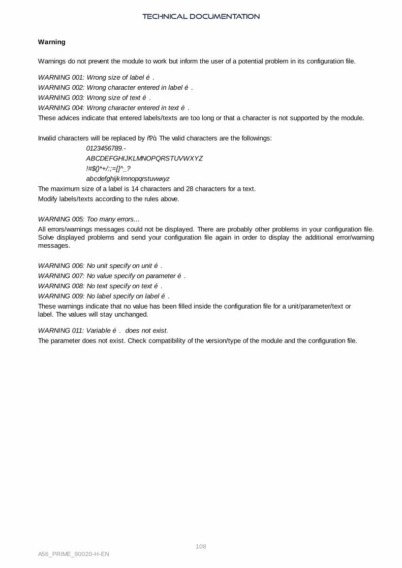
TECHNICAL DOCUMENTATION
108A56_PRIME_90020-H-EN
Warning
Warnings do not prevent the module to work but inform the user of a potential problem in its configuration file.
WARNING 001: Wrong size of label ….
WARNING 002: Wrong character entered in label ….
WARNING 003: Wrong size of text ….
WARNING 004: Wrong character entered in text ….
These advices indicate that entered labels/texts are too long or that a character is not supported by the module.
Invalid characters will be replaced by “?”. The valid characters are the followings:
0123456789.-
ABCDEFGHIJKLMNOPQRSTUVWXYZ
!#$()*+/:;=[]^_?
abcdefghijk lmnopqrstuvwxyz
The maximum size of a label is 14 characters and 28 characters for a text.
Modify labels/texts according to the rules above.
WARNING 005: Too many errors...
All errors/warnings messages could not be displayed. There are probably other problems in your configuration file.Solve displayed problems and send your configuration file again in order to display the additional error/warningmessages.
WARNING 006: No unit specify on unit ….
WARNING 007: No value specify on parameter ….
WARNING 008: No text specify on text ….
WARNING 009: No label specify on label ….
These warnings indicate that no value has been filled inside the configuration file for a unit/parameter/text orlabel. The values will stay unchanged.
WARNING 011: Variable …. does not exist.
The parameter does not exist. Check compatibility of the version/type of the module and the configuration file.

TECHNICAL DOCUMENTATION
109A56_PRIME_90020-H-EN
Standards for Generator
ISO 8528-1 CLASSES AND POWER DESIGNATIONS
Various load-duration profiles are defined. Here is the correspondence between classes and powers:
RunISO
designationConditions
Powerdesignation
Conditions Controller
Unlimited # ofhours
PRIMERATING
Allowable average power outputover a 24-hour period is 70% ofthe prime rating. 10% overload.
Prime RunningPower (changingload).
Overload: max: 1 hover a 12-h periodtotal: 25 h/ year.
GENSYSCOMPACT
PRIME
CONTINUOUS RATING(base loadrating)
Continuousoperating power.
Fixed load.ACGEN2.0
(noparalleling)
Limited# of
hours
STANDBYRATING
Maximum 200 hours per year.Allowable average power outputover a 24-hour period is 70% ofthe standby rating. No overload.
Emergencystand-by power(changing load).
25h/ year at 100%.No overload200 h/year at 80%
TCGEN2.0(no
paralleling)MISSION-CRITICALRATING
Maximum 500 hours per year.Allowable average power outputis 85% of the nameplate rating.
Limited-timerunning power.
Fixed load.
ISO 3046
· Part 1: Power: DBR (intermittent) and MCR (Max Continuous Rating).The COMPACT RANGE offers the possibility to activate air conditioning and a cooling fan.
· Part 4: Speed governor
Governor performance classes G1 G2 G3 G4
Speed droop ≤ 8% ≤ 5% ≤ 3% By agreement
Regulation stages P, PI or PID P, PI or PID PI or PID PI or PID
NEC700 and NFPA110
Start in static paralleling to meet the 10s time limit (NEC700). Type 10 as per NFPA110.According to NFPA110, Black start is where the stored energy system has the capability to start the prime moverwithout using energy from another source. Such a Generator can be used to start a turbine.NFA110 defines classes according to fuel tank autonomy; it requires that emergency power supply hasa manual remote stop (A5.6.5.6). NFA110 fault list includes 15 signals (warning or shut-down).

TECHNICAL DOCUMENTATION
110A56_PRIME_90020-H-EN
Certifications
DECLARATION OF CONFORMITY

TECHNICAL DOCUMENTATION
111A56_PRIME_90020-H-EN
ISO CERTIFICATe - 2015

TECHNICAL DOCUMENTATION
112A56_PRIME_90020-H-EN
Download the certification

TECHNICAL DOCUMENTATION
113A56_PRIME_90020-H-EN
Software Variables

List of variables
Controller dynamic settings 115Speed control . . . . . . . . . . . . . . . . . . . . . . . . . . . . . . . . . . . . . . . . . . . . . . . . . . 115
Amplitude (2205) . . . . . . . . . . . . . . . . . . . . . . . . . . . . . . . . . . . 115Offset (2206) . . . . . . . . . . . . . . . . . . . . . . . . . . . . . . . . . . . . . 115Droop (frequency) (2204) . . . . . . . . . . . . . . . . . . . . . . . . . . . . . . 115Speed output inversion (2212) . . . . . . . . . . . . . . . . . . . . . . . . . . . . 115Dead band (3650) . . . . . . . . . . . . . . . . . . . . . . . . . . . . . . . . . . 115Frequency pulse divider (3652) . . . . . . . . . . . . . . . . . . . . . . . . . . . . 115
AVR control . . . . . . . . . . . . . . . . . . . . . . . . . . . . . . . . . . . . . . . . . . . . . . . . . . . 116AVR Amplitude (2251) . . . . . . . . . . . . . . . . . . . . . . . . . . . . . . . . 116AVR Offset (2252) . . . . . . . . . . . . . . . . . . . . . . . . . . . . . . . . . . 116Droop (voltage) (2250) . . . . . . . . . . . . . . . . . . . . . . . . . . . . . . . 116AVR signal output inversion (2254) . . . . . . . . . . . . . . . . . . . . . . . . . 116Dead Band (3651) . . . . . . . . . . . . . . . . . . . . . . . . . . . . . . . . . . 116Voltage pulse divider (3653) . . . . . . . . . . . . . . . . . . . . . . . . . . . . . 116
Synchronization PID . . . . . . . . . . . . . . . . . . . . . . . . . . . . . . . . . . . . . . . . . . . . . . . 117Frequency . . . . . . . . . . . . . . . . . . . . . . . . . . . . . . . . . . . . . . . . . . . . . . . . . 117
Frequency Global Gain (2900) . . . . . . . . . . . . . . . . . . . . . . . . . . . . 117Frequency Proportional Gain (2901) . . . . . . . . . . . . . . . . . . . . . . . . . 117Frequency Integral Gain (2902) . . . . . . . . . . . . . . . . . . . . . . . . . . . 117Frequency Derivate Gain (2903) . . . . . . . . . . . . . . . . . . . . . . . . . . . 117
Phase . . . . . . . . . . . . . . . . . . . . . . . . . . . . . . . . . . . . . . . . . . . . . . . . . . . 118Phase Global Gain (2904) . . . . . . . . . . . . . . . . . . . . . . . . . . . . . . 118Phase Proportional Gain (2905) . . . . . . . . . . . . . . . . . . . . . . . . . . . 118Phase Integral Gain (2906) . . . . . . . . . . . . . . . . . . . . . . . . . . . . . . 118Phase Derivate Gain (2907) . . . . . . . . . . . . . . . . . . . . . . . . . . . . . 118
Voltage . . . . . . . . . . . . . . . . . . . . . . . . . . . . . . . . . . . . . . . . . . . . . . . . . . . 118Voltage Global Gain (2950) . . . . . . . . . . . . . . . . . . . . . . . . . . . . . 118Voltage Proportional Gain (2951) . . . . . . . . . . . . . . . . . . . . . . . . . . 118Voltage Integral Gain (2952) . . . . . . . . . . . . . . . . . . . . . . . . . . . . . 119Voltage Derivate Gain (2953) . . . . . . . . . . . . . . . . . . . . . . . . . . . . 119
kW/kVAR PID . . . . . . . . . . . . . . . . . . . . . . . . . . . . . . . . . . . . . . . . . . . . . . . . . 119Active power . . . . . . . . . . . . . . . . . . . . . . . . . . . . . . . . . . . . . . . . . . . . . . . . 119
kW Global Gain (2908) . . . . . . . . . . . . . . . . . . . . . . . . . . . . . . . . 119kW Proportional Gain (2909) . . . . . . . . . . . . . . . . . . . . . . . . . . . . 119kW Integral Gain (2910) . . . . . . . . . . . . . . . . . . . . . . . . . . . . . . . 119kW Derivate Gain (2911) . . . . . . . . . . . . . . . . . . . . . . . . . . . . . . 119
Reactive power . . . . . . . . . . . . . . . . . . . . . . . . . . . . . . . . . . . . . . . . . . . . . . 120kVAR Global Gain (2954) . . . . . . . . . . . . . . . . . . . . . . . . . . . . . . 120kVAR Proportional Gain (2955) . . . . . . . . . . . . . . . . . . . . . . . . . . . 120kVAR Integral Gain (2956) . . . . . . . . . . . . . . . . . . . . . . . . . . . . . . 120kVAR Derivate Gain (2957) . . . . . . . . . . . . . . . . . . . . . . . . . . . . . 120
Frequency . . . . . . . . . . . . . . . . . . . . . . . . . . . . . . . . . . . . . . . . . . . . . . . . . 120Frequency centering (2914) . . . . . . . . . . . . . . . . . . . . . . . . . . . . . 120
Voltage . . . . . . . . . . . . . . . . . . . . . . . . . . . . . . . . . . . . . . . . . . . . . . . . . . . 120Voltage centering (2958) . . . . . . . . . . . . . . . . . . . . . . . . . . . . . . . 120
Configuration 120General . . . . . . . . . . . . . . . . . . . . . . . . . . . . . . . . . . . . . . . . . . . . . . . . . . . . . . 121
General . . . . . . . . . . . . . . . . . . . . . . . . . . . . . . . . . . . . . . . . . . . . . . . . . . . 121My number (2001) . . . . . . . . . . . . . . . . . . . . . . . . . . . . . . . . . . 121Number of generator (2000) . . . . . . . . . . . . . . . . . . . . . . . . . . . . . 121Number of MASTER/BTB (2017) . . . . . . . . . . . . . . . . . . . . . . . . . 121Segment number (2020) . . . . . . . . . . . . . . . . . . . . . . . . . . . . . . . 121Voltage system (2003) . . . . . . . . . . . . . . . . . . . . . . . . . . . . . . . . 121Dead bus management (2002) . . . . . . . . . . . . . . . . . . . . . . . . . . . . 121Inhib. remote start MASTER (2018) . . . . . . . . . . . . . . . . . . . . . . . . 122
Mode . . . . . . . . . . . . . . . . . . . . . . . . . . . . . . . . . . . . . . . . . . . . . . . . . . . . 122
A56 PRIME 90020-H-EN114

Power up in mode (2012) . . . . . . . . . . . . . . . . . . . . . . . . . . . . . . 122Test mode (2014) . . . . . . . . . . . . . . . . . . . . . . . . . . . . . . . . . . 122Test active timer on (2015) . . . . . . . . . . . . . . . . . . . . . . . . . . . . . 122Test active timer (2016) . . . . . . . . . . . . . . . . . . . . . . . . . . . . . . . 122
Generator . . . . . . . . . . . . . . . . . . . . . . . . . . . . . . . . . . . . . . . . . . . . . . . . . . . . 123Generator . . . . . . . . . . . . . . . . . . . . . . . . . . . . . . . . . . . . . . . . . . . . . . . . . 123
Nominal kW active power (2105) . . . . . . . . . . . . . . . . . . . . . . . . . . 123Nominal kVAR reactive power (2106) . . . . . . . . . . . . . . . . . . . . . . . . 123Nominal voltage (2102) . . . . . . . . . . . . . . . . . . . . . . . . . . . . . . . 123PT ratio (2100) . . . . . . . . . . . . . . . . . . . . . . . . . . . . . . . . . . . 123CT ratio (2101) . . . . . . . . . . . . . . . . . . . . . . . . . . . . . . . . . . . 123Low kW active power threshold (2866) . . . . . . . . . . . . . . . . . . . . . . . 124High kW active power threshold (2867) . . . . . . . . . . . . . . . . . . . . . . . 124
Setpoint . . . . . . . . . . . . . . . . . . . . . . . . . . . . . . . . . . . . . . . . . . . . . . . . . . 124kW mode (2013) . . . . . . . . . . . . . . . . . . . . . . . . . . . . . . . . . . . 124Base load kW setpoint (2107) . . . . . . . . . . . . . . . . . . . . . . . . . . . . 124Power factor setpoint (inductive) (2253) . . . . . . . . . . . . . . . . . . . . . . 124
Bus . . . . . . . . . . . . . . . . . . . . . . . . . . . . . . . . . . . . . . . . . . . . . . . . . . . . . . . . 125BUS nominal voltage (2152) . . . . . . . . . . . . . . . . . . . . . . . . . . . . . 125PT ratio (2150) . . . . . . . . . . . . . . . . . . . . . . . . . . . . . . . . . . . 125
Engine . . . . . . . . . . . . . . . . . . . . . . . . . . . . . . . . . . . . . . . . . . . . . . . . . . . . . . 125General . . . . . . . . . . . . . . . . . . . . . . . . . . . . . . . . . . . . . . . . . . . . . . . . . . . 125
Engine type (3477) . . . . . . . . . . . . . . . . . . . . . . . . . . . . . . . . . . 125Speed sensor type (2200) . . . . . . . . . . . . . . . . . . . . . . . . . . . . . . 125Number of poles pair (2202) . . . . . . . . . . . . . . . . . . . . . . . . . . . . . 125Number of teeth for pick-up (2201) . . . . . . . . . . . . . . . . . . . . . . . . . 125Oil pressure switch (3450) . . . . . . . . . . . . . . . . . . . . . . . . . . . . . . 126Coolant temperature switch (3451) . . . . . . . . . . . . . . . . . . . . . . . . . 126Speed setpoint (2207) . . . . . . . . . . . . . . . . . . . . . . . . . . . . . . . . 126Idle speed (3468) . . . . . . . . . . . . . . . . . . . . . . . . . . . . . . . . . . . 126
Start/Stop settings . . . . . . . . . . . . . . . . . . . . . . . . . . . . . . . . . . . . . . . . . . . . 126Start sequence . . . . . . . . . . . . . . . . . . . . . . . . . . . . . . . . . . . . . . . . . . . 126
External start sequence (3452) . . . . . . . . . . . . . . . . . . . . . . . . . . . . 126Fail to start engine (3453) . . . . . . . . . . . . . . . . . . . . . . . . . . . . . . 126Engine not ready (3454) . . . . . . . . . . . . . . . . . . . . . . . . . . . . . . . 127Warm up selection (3479) . . . . . . . . . . . . . . . . . . . . . . . . . . . . . . 127
Check before start . . . . . . . . . . . . . . . . . . . . . . . . . . . . . . . . . . . . . . . . . 127Preheating coolant temperature threshold (3474) . . . . . . . . . . . . . . . . . . 127Minimum oil prelubrication threshold (3473) . . . . . . . . . . . . . . . . . . . . 127Cooling fan activation threshold (3475) . . . . . . . . . . . . . . . . . . . . . . . 127
Stop sequence . . . . . . . . . . . . . . . . . . . . . . . . . . . . . . . . . . . . . . . . . . . 127Cooling speed selection (3476) . . . . . . . . . . . . . . . . . . . . . . . . . . . . 127
Crank settings . . . . . . . . . . . . . . . . . . . . . . . . . . . . . . . . . . . . . . . . . . . . . . . 128Maximum starting attempts by starter (3461) . . . . . . . . . . . . . . . . . . . 128Time between start attemps (3458) . . . . . . . . . . . . . . . . . . . . . . . . . 128Minimum cranking (3466) . . . . . . . . . . . . . . . . . . . . . . . . . . . . . . 128Maximum cranking (3457) . . . . . . . . . . . . . . . . . . . . . . . . . . . . . . 128Starter order (3459) . . . . . . . . . . . . . . . . . . . . . . . . . . . . . . . . . 128Default starter number (3460) . . . . . . . . . . . . . . . . . . . . . . . . . . . . 128Crank 1 drop out (3462) . . . . . . . . . . . . . . . . . . . . . . . . . . . . . . . 128Crank 2 drop out (3463) . . . . . . . . . . . . . . . . . . . . . . . . . . . . . . . 129Crank 3 drop out (3464) . . . . . . . . . . . . . . . . . . . . . . . . . . . . . . . 129
AVR excitation . . . . . . . . . . . . . . . . . . . . . . . . . . . . . . . . . . . . . . . . . . . . . . . 129Excitation (2050) . . . . . . . . . . . . . . . . . . . . . . . . . . . . . . . . . . . 129Excit. speed (2053) . . . . . . . . . . . . . . . . . . . . . . . . . . . . . . . . . . 129Excit. volt. (2054) . . . . . . . . . . . . . . . . . . . . . . . . . . . . . . . . . . 129Voltage stabilisation (only static paralleling) (2056) . . . . . . . . . . . . . . . . 129
J1939 . . . . . . . . . . . . . . . . . . . . . . . . . . . . . . . . . . . . . . . . . . . . . . . . . . . 129Manufacturer (3100) . . . . . . . . . . . . . . . . . . . . . . . . . . . . . . . . . 129ECU type (3101) . . . . . . . . . . . . . . . . . . . . . . . . . . . . . . . . . . . 130
Inputs . . . . . . . . . . . . . . . . . . . . . . . . . . . . . . . . . . . . . . . . . . . . . . . . . . . . . . 130
A56 PRIME 90020-H-EN115

Digital inputs . . . . . . . . . . . . . . . . . . . . . . . . . . . . . . . . . . . . . . . . . . . . . . . 130Input 1 (Customisable) (250) . . . . . . . . . . . . . . . . . . . . . . . . . . . . 130Input 2 (Customisable) (251) . . . . . . . . . . . . . . . . . . . . . . . . . . . . 130Input 3 (Customisable) (252) . . . . . . . . . . . . . . . . . . . . . . . . . . . . 130Input 4 (Customisable) (253) . . . . . . . . . . . . . . . . . . . . . . . . . . . . 130Input 5 (Customisable) (254) . . . . . . . . . . . . . . . . . . . . . . . . . . . . 130Input 6 (Customisable) (255) . . . . . . . . . . . . . . . . . . . . . . . . . . . . 130Input 7 (Customisable) (256) . . . . . . . . . . . . . . . . . . . . . . . . . . . . 131Input 8 (Customisable) (257) . . . . . . . . . . . . . . . . . . . . . . . . . . . . 131Input 9 (Customisable) (258) . . . . . . . . . . . . . . . . . . . . . . . . . . . . 131
Hysteresis DI . . . . . . . . . . . . . . . . . . . . . . . . . . . . . . . . . . . . . . . . . . . . . . . . 131Hysteresis DI 1 . . . . . . . . . . . . . . . . . . . . . . . . . . . . . . . . . . . . . . . . . . 131
Hysteresis 1 enable for DI (2769) . . . . . . . . . . . . . . . . . . . . . . . . . . 131Timer (2777) . . . . . . . . . . . . . . . . . . . . . . . . . . . . . . . . . . . . . 131Direction (2785) . . . . . . . . . . . . . . . . . . . . . . . . . . . . . . . . . . . 131
Hysteresis DI 2 . . . . . . . . . . . . . . . . . . . . . . . . . . . . . . . . . . . . . . . . . . 131Hysteresis 2 enable for DI (2770) . . . . . . . . . . . . . . . . . . . . . . . . . . 131Timer (2778) . . . . . . . . . . . . . . . . . . . . . . . . . . . . . . . . . . . . . 132Direction (2786) . . . . . . . . . . . . . . . . . . . . . . . . . . . . . . . . . . . 132
Hysteresis DI 3 . . . . . . . . . . . . . . . . . . . . . . . . . . . . . . . . . . . . . . . . . . 132Hysteresis 3 enable for DI (2771) . . . . . . . . . . . . . . . . . . . . . . . . . . 132Timer (2779) . . . . . . . . . . . . . . . . . . . . . . . . . . . . . . . . . . . . . 132Direction (2787) . . . . . . . . . . . . . . . . . . . . . . . . . . . . . . . . . . . 132
Hysteresis DI 4 . . . . . . . . . . . . . . . . . . . . . . . . . . . . . . . . . . . . . . . . . . 132Hysteresis 4 enable for DI (2772) . . . . . . . . . . . . . . . . . . . . . . . . . . 132Timer (2780) . . . . . . . . . . . . . . . . . . . . . . . . . . . . . . . . . . . . . 132Direction (2788) . . . . . . . . . . . . . . . . . . . . . . . . . . . . . . . . . . . 133
Hysteresis DI 5 . . . . . . . . . . . . . . . . . . . . . . . . . . . . . . . . . . . . . . . . . . 133Hysteresis 5 enable for DI (2773) . . . . . . . . . . . . . . . . . . . . . . . . . . 133Timer (2781) . . . . . . . . . . . . . . . . . . . . . . . . . . . . . . . . . . . . . 133Direction (2789) . . . . . . . . . . . . . . . . . . . . . . . . . . . . . . . . . . . 133
Hysteresis DI 6 . . . . . . . . . . . . . . . . . . . . . . . . . . . . . . . . . . . . . . . . . . 133Hysteresis 6 enable for DI (2774) . . . . . . . . . . . . . . . . . . . . . . . . . . 133Timer (2782) . . . . . . . . . . . . . . . . . . . . . . . . . . . . . . . . . . . . . 133Direction (2790) . . . . . . . . . . . . . . . . . . . . . . . . . . . . . . . . . . . 133
Hysteresis DI 7 . . . . . . . . . . . . . . . . . . . . . . . . . . . . . . . . . . . . . . . . . . 134Hysteresis 7 enable for DI (2775) . . . . . . . . . . . . . . . . . . . . . . . . . . 134Timer (2783) . . . . . . . . . . . . . . . . . . . . . . . . . . . . . . . . . . . . . 134Direction (2791) . . . . . . . . . . . . . . . . . . . . . . . . . . . . . . . . . . . 134
Hysteresis DI 8 . . . . . . . . . . . . . . . . . . . . . . . . . . . . . . . . . . . . . . . . . . 134Hysteresis 8 enable for DI (2776) . . . . . . . . . . . . . . . . . . . . . . . . . . 134Timer (2784) . . . . . . . . . . . . . . . . . . . . . . . . . . . . . . . . . . . . . 134Direction (2792) . . . . . . . . . . . . . . . . . . . . . . . . . . . . . . . . . . . 134
Analog inputs . . . . . . . . . . . . . . . . . . . . . . . . . . . . . . . . . . . . . . . . . . . . . . . 134Analog 1 (Customisable) (150) . . . . . . . . . . . . . . . . . . . . . . . . . . . 134Analog 2 (Customisable) (151) . . . . . . . . . . . . . . . . . . . . . . . . . . . 135Analog 3 (Customisable) (152) . . . . . . . . . . . . . . . . . . . . . . . . . . . 135
Hysteresis AI . . . . . . . . . . . . . . . . . . . . . . . . . . . . . . . . . . . . . . . . . . . . . . . . 135Hysteresis AI 1 . . . . . . . . . . . . . . . . . . . . . . . . . . . . . . . . . . . . . . . . . . 135
Activating Hysteresis on Analog Input 1 (2657) . . . . . . . . . . . . . . . . . . . 135Low level threshold (2660) . . . . . . . . . . . . . . . . . . . . . . . . . . . . . . 135Timer on low level threshold (2666) . . . . . . . . . . . . . . . . . . . . . . . . . 135High level threshold (2663) . . . . . . . . . . . . . . . . . . . . . . . . . . . . . 135Timer on high level threshold (2669) . . . . . . . . . . . . . . . . . . . . . . . . 135Hysteresis Direction on Analog Input 1 (2672) . . . . . . . . . . . . . . . . . . . 136
Hysteresis AI 2 . . . . . . . . . . . . . . . . . . . . . . . . . . . . . . . . . . . . . . . . . . 136Activating Hysteresis on Analog Input 2 (2658) . . . . . . . . . . . . . . . . . . . 136Low level threshold (2661) . . . . . . . . . . . . . . . . . . . . . . . . . . . . . . 136Timer on low level threshold (2667) . . . . . . . . . . . . . . . . . . . . . . . . . 136High level threshold (2664) . . . . . . . . . . . . . . . . . . . . . . . . . . . . . 136Timer on high level threshold (2670) . . . . . . . . . . . . . . . . . . . . . . . . 136
A56 PRIME 90020-H-EN116

Hysteresis Direction on Analog Input 2 (2673) . . . . . . . . . . . . . . . . . . . 136Hysteresis AI 3 . . . . . . . . . . . . . . . . . . . . . . . . . . . . . . . . . . . . . . . . . . 137
Activating Hysteresis on Analog Input 3 (2659) . . . . . . . . . . . . . . . . . . . 137Low level threshold (2662) . . . . . . . . . . . . . . . . . . . . . . . . . . . . . . 137Timer on low level threshold (2668) . . . . . . . . . . . . . . . . . . . . . . . . . 137High level threshold (2665) . . . . . . . . . . . . . . . . . . . . . . . . . . . . . 137Timer on high level threshold (2671) . . . . . . . . . . . . . . . . . . . . . . . . 137Hysteresis Direction on Analog Input 3 (2674) . . . . . . . . . . . . . . . . . . . 137
Outputs . . . . . . . . . . . . . . . . . . . . . . . . . . . . . . . . . . . . . . . . . . . . . . . . . . . . . 137Digital/relays outputs . . . . . . . . . . . . . . . . . . . . . . . . . . . . . . . . . . . . . . . . . . . 137
Digital outputs . . . . . . . . . . . . . . . . . . . . . . . . . . . . . . . . . . . . . . . . . . 137Status Digital Output 1 (4350) . . . . . . . . . . . . . . . . . . . . . . . . . . . 137Status Digital Output 2 (4351) . . . . . . . . . . . . . . . . . . . . . . . . . . . 138Status Digital Output 3 (4352) . . . . . . . . . . . . . . . . . . . . . . . . . . . 138Status Digital Output 4 (4353) . . . . . . . . . . . . . . . . . . . . . . . . . . . 138Status Digital Output 5 (4354) . . . . . . . . . . . . . . . . . . . . . . . . . . . 138Status Digital Output 6 (4355) . . . . . . . . . . . . . . . . . . . . . . . . . . . 138
Relay outputs . . . . . . . . . . . . . . . . . . . . . . . . . . . . . . . . . . . . . . . . . . . 138Status Relay Output 1 (4356) . . . . . . . . . . . . . . . . . . . . . . . . . . . . 138Status Relay Output 2 (4357) . . . . . . . . . . . . . . . . . . . . . . . . . . . . 138
Generator breaker . . . . . . . . . . . . . . . . . . . . . . . . . . . . . . . . . . . . . . . . . . . . . 139Control . . . . . . . . . . . . . . . . . . . . . . . . . . . . . . . . . . . . . . . . . . . . . . . 139
Generator circuit breaker control type (2300) . . . . . . . . . . . . . . . . . . . . 139Pulse . . . . . . . . . . . . . . . . . . . . . . . . . . . . . . . . . . . . . . . . . . . . . . . . 139
Gen CB control Pulse length (2301) . . . . . . . . . . . . . . . . . . . . . . . . . 139Undervoltage coil hold time GCB (2302) . . . . . . . . . . . . . . . . . . . . . . 139Undervoltage coil security timer GCB (2303) . . . . . . . . . . . . . . . . . . . . 139
Generator protections . . . . . . . . . . . . . . . . . . . . . . . . . . . . . . . . . . . . . . . . . . . . . . 139Over/under frequency . . . . . . . . . . . . . . . . . . . . . . . . . . . . . . . . . . . . . . . . . . . 139
Over frequency . . . . . . . . . . . . . . . . . . . . . . . . . . . . . . . . . . . . . . . . . . 139Over frequency threshold (2400) . . . . . . . . . . . . . . . . . . . . . . . . . . . 139Over frequency timer (2401) . . . . . . . . . . . . . . . . . . . . . . . . . . . . . 139Over frequency control (2402) . . . . . . . . . . . . . . . . . . . . . . . . . . . . 140
Under frequency . . . . . . . . . . . . . . . . . . . . . . . . . . . . . . . . . . . . . . . . . . 140Under frequency threshold (2403) . . . . . . . . . . . . . . . . . . . . . . . . . . 140Under frequency timer (2404) . . . . . . . . . . . . . . . . . . . . . . . . . . . . 140Under frequency control (2405) . . . . . . . . . . . . . . . . . . . . . . . . . . . 140
Over frequency 2 . . . . . . . . . . . . . . . . . . . . . . . . . . . . . . . . . . . . . . . . . 141Over frequency threshold 2 (2436) . . . . . . . . . . . . . . . . . . . . . . . . . . 141Over frequency timer 2 (2437) . . . . . . . . . . . . . . . . . . . . . . . . . . . . 141Over frequency control 2 (2438) . . . . . . . . . . . . . . . . . . . . . . . . . . . 141
Under frequency 2 . . . . . . . . . . . . . . . . . . . . . . . . . . . . . . . . . . . . . . . . . 141Under frequency threshold 2 (2439) . . . . . . . . . . . . . . . . . . . . . . . . . 141Under frequency timer 2 (2440) . . . . . . . . . . . . . . . . . . . . . . . . . . . 141Under frequency control 2 (2441) . . . . . . . . . . . . . . . . . . . . . . . . . . 141
Over/under voltage . . . . . . . . . . . . . . . . . . . . . . . . . . . . . . . . . . . . . . . . . . . . 142Over voltage . . . . . . . . . . . . . . . . . . . . . . . . . . . . . . . . . . . . . . . . . . . . 142
Over voltage threshold (2406) . . . . . . . . . . . . . . . . . . . . . . . . . . . . 142Over voltage timer (2407) . . . . . . . . . . . . . . . . . . . . . . . . . . . . . . 142Over voltage control (2408) . . . . . . . . . . . . . . . . . . . . . . . . . . . . . 142
Under voltage . . . . . . . . . . . . . . . . . . . . . . . . . . . . . . . . . . . . . . . . . . . 143Under voltage threshold (2409) . . . . . . . . . . . . . . . . . . . . . . . . . . . 143Under voltage timer (2410) . . . . . . . . . . . . . . . . . . . . . . . . . . . . . 143Under voltage control (2411) . . . . . . . . . . . . . . . . . . . . . . . . . . . . 143
Over voltage 2 . . . . . . . . . . . . . . . . . . . . . . . . . . . . . . . . . . . . . . . . . . . 143Over voltage threshold 2 (2442) . . . . . . . . . . . . . . . . . . . . . . . . . . . 143Over voltage timer 2 (2443) . . . . . . . . . . . . . . . . . . . . . . . . . . . . . 143Over voltage control 2 (2444) . . . . . . . . . . . . . . . . . . . . . . . . . . . . 143
Under voltage 2 . . . . . . . . . . . . . . . . . . . . . . . . . . . . . . . . . . . . . . . . . . 144Under voltage threshold 2 (2445) . . . . . . . . . . . . . . . . . . . . . . . . . . 144Under voltage timer 2 (2446) . . . . . . . . . . . . . . . . . . . . . . . . . . . . 144
A56 PRIME 90020-H-EN117

Under voltage control 2 (2447) . . . . . . . . . . . . . . . . . . . . . . . . . . . 144Over current/neutral . . . . . . . . . . . . . . . . . . . . . . . . . . . . . . . . . . . . . . . . . . . 145
Over current . . . . . . . . . . . . . . . . . . . . . . . . . . . . . . . . . . . . . . . . . . . . 145Over current threshold (2430) . . . . . . . . . . . . . . . . . . . . . . . . . . . . 145Over current timer (2431) . . . . . . . . . . . . . . . . . . . . . . . . . . . . . . 145Over current control (2432) . . . . . . . . . . . . . . . . . . . . . . . . . . . . . 145
Neutral current . . . . . . . . . . . . . . . . . . . . . . . . . . . . . . . . . . . . . . . . . . 145Neutral current threshold (2433) . . . . . . . . . . . . . . . . . . . . . . . . . . 145Neutral current timer (2434) . . . . . . . . . . . . . . . . . . . . . . . . . . . . . 145Neutral current control (2435) . . . . . . . . . . . . . . . . . . . . . . . . . . . . 146
Over current 2 . . . . . . . . . . . . . . . . . . . . . . . . . . . . . . . . . . . . . . . . . . . 146Over current threshold 2 (2466) . . . . . . . . . . . . . . . . . . . . . . . . . . . 146Over current timer 2 (2467) . . . . . . . . . . . . . . . . . . . . . . . . . . . . . 146Over current control 2 (2468) . . . . . . . . . . . . . . . . . . . . . . . . . . . . 146
Neutral current 2 . . . . . . . . . . . . . . . . . . . . . . . . . . . . . . . . . . . . . . . . . 147Neutral current threshold 2 (2469) . . . . . . . . . . . . . . . . . . . . . . . . . 147Neutral current timer 2 (2470) . . . . . . . . . . . . . . . . . . . . . . . . . . . . 147Neutral current control 2 (2471) . . . . . . . . . . . . . . . . . . . . . . . . . . . 147
Reverse kW/kVAR . . . . . . . . . . . . . . . . . . . . . . . . . . . . . . . . . . . . . . . . . . . . . 147Reverse kW . . . . . . . . . . . . . . . . . . . . . . . . . . . . . . . . . . . . . . . . . . . . 147
Reverse kW threshold (2418) . . . . . . . . . . . . . . . . . . . . . . . . . . . . 147Reverse kW timer (2419) . . . . . . . . . . . . . . . . . . . . . . . . . . . . . . 147Reverse kW control (2420) . . . . . . . . . . . . . . . . . . . . . . . . . . . . . . 148
Reverse kVAR . . . . . . . . . . . . . . . . . . . . . . . . . . . . . . . . . . . . . . . . . . . 148Reverse kVAR threshold (2427) . . . . . . . . . . . . . . . . . . . . . . . . . . . 148Reverse kVAR timer (2428) . . . . . . . . . . . . . . . . . . . . . . . . . . . . . 148Reverse kVAR control (2429) . . . . . . . . . . . . . . . . . . . . . . . . . . . . 148
Reverse kW 2 . . . . . . . . . . . . . . . . . . . . . . . . . . . . . . . . . . . . . . . . . . . 149Reverse kW threshold 2 (2454) . . . . . . . . . . . . . . . . . . . . . . . . . . . 149Reverse kW timer 2 (2455) . . . . . . . . . . . . . . . . . . . . . . . . . . . . . 149Reverse kW control 2 (2456) . . . . . . . . . . . . . . . . . . . . . . . . . . . . 149
Reverse kVAR 2 . . . . . . . . . . . . . . . . . . . . . . . . . . . . . . . . . . . . . . . . . . 149Reverse kVAR threshold 2 (2463) . . . . . . . . . . . . . . . . . . . . . . . . . . 149Reverse kVAR timer 2 (2464) . . . . . . . . . . . . . . . . . . . . . . . . . . . . 149Reverse kVAR control 2 (2465) . . . . . . . . . . . . . . . . . . . . . . . . . . . 149
Maxi kW/mini kW . . . . . . . . . . . . . . . . . . . . . . . . . . . . . . . . . . . . . . . . . . . . 150Maxi kW . . . . . . . . . . . . . . . . . . . . . . . . . . . . . . . . . . . . . . . . . . . . . . 150
Maximum kW threshold (2415) . . . . . . . . . . . . . . . . . . . . . . . . . . . 150Maximum kW timer (2416) . . . . . . . . . . . . . . . . . . . . . . . . . . . . . 150Maximum kW control (2417) . . . . . . . . . . . . . . . . . . . . . . . . . . . . 150
Mini kW . . . . . . . . . . . . . . . . . . . . . . . . . . . . . . . . . . . . . . . . . . . . . . 151Minimum kW threshold (2412) . . . . . . . . . . . . . . . . . . . . . . . . . . . 151Minimum kW timer (2413) . . . . . . . . . . . . . . . . . . . . . . . . . . . . . 151Minimum kW control (2414) . . . . . . . . . . . . . . . . . . . . . . . . . . . . . 151
Maxi kW 2 . . . . . . . . . . . . . . . . . . . . . . . . . . . . . . . . . . . . . . . . . . . . . 151Maximum kW threshold 2 (2451) . . . . . . . . . . . . . . . . . . . . . . . . . . 151Maximum kW timer 2 (2452) . . . . . . . . . . . . . . . . . . . . . . . . . . . . 151Maximum kW control 2 (2453) . . . . . . . . . . . . . . . . . . . . . . . . . . . 151
Mini kW 2 . . . . . . . . . . . . . . . . . . . . . . . . . . . . . . . . . . . . . . . . . . . . . 152Minimum kW threshold 2 (2448) . . . . . . . . . . . . . . . . . . . . . . . . . . 152Minimum kW timer 2 (2449) . . . . . . . . . . . . . . . . . . . . . . . . . . . . 152Minimum kW control 2 (2450) . . . . . . . . . . . . . . . . . . . . . . . . . . . 152
Maxi kVAR/Mini kVAR . . . . . . . . . . . . . . . . . . . . . . . . . . . . . . . . . . . . . . . . . . 153Maxi kVAR . . . . . . . . . . . . . . . . . . . . . . . . . . . . . . . . . . . . . . . . . . . . 153
Maximum kVAR threshold (2424) . . . . . . . . . . . . . . . . . . . . . . . . . . 153Maximum kVAR timer (2425) . . . . . . . . . . . . . . . . . . . . . . . . . . . . 153Maximum kVAR control (2426) . . . . . . . . . . . . . . . . . . . . . . . . . . . 153
Mini kVar . . . . . . . . . . . . . . . . . . . . . . . . . . . . . . . . . . . . . . . . . . . . . 153Minimum kVAR threshold (2421) . . . . . . . . . . . . . . . . . . . . . . . . . . 153Minimum kVAR timer (2422) . . . . . . . . . . . . . . . . . . . . . . . . . . . . 153Minimum kVAR control (2423) . . . . . . . . . . . . . . . . . . . . . . . . . . . 154
A56 PRIME 90020-H-EN118

Maxi kVAR 2 . . . . . . . . . . . . . . . . . . . . . . . . . . . . . . . . . . . . . . . . . . . 154Maximum kVAR threshold 2 (2460) . . . . . . . . . . . . . . . . . . . . . . . . . 154Maximum kVAR timer 2 (2461) . . . . . . . . . . . . . . . . . . . . . . . . . . . 154Maximum kVAR control 2 (2462) . . . . . . . . . . . . . . . . . . . . . . . . . . 154
Mini kVar 2 . . . . . . . . . . . . . . . . . . . . . . . . . . . . . . . . . . . . . . . . . . . . 155Minimum kVAR threshold 2 (2457) . . . . . . . . . . . . . . . . . . . . . . . . . 155Minimum kVAR timer 2 (2458) . . . . . . . . . . . . . . . . . . . . . . . . . . . 155Minimum kVAR control 2 (2459) . . . . . . . . . . . . . . . . . . . . . . . . . . 155
Voltage/Current unbalance . . . . . . . . . . . . . . . . . . . . . . . . . . . . . . . . . . . . . . . . 155Voltage unbalance . . . . . . . . . . . . . . . . . . . . . . . . . . . . . . . . . . . . . . . . . 155
Voltage unbalance threshold (2486) . . . . . . . . . . . . . . . . . . . . . . . . . 155Voltage unbalance timer (2487) . . . . . . . . . . . . . . . . . . . . . . . . . . . 155Voltage unbalance control (2488) . . . . . . . . . . . . . . . . . . . . . . . . . . 156
Current unbalance . . . . . . . . . . . . . . . . . . . . . . . . . . . . . . . . . . . . . . . . . 156Current unbalance threshold (2492) . . . . . . . . . . . . . . . . . . . . . . . . . 156Current unbalance timer (2493) . . . . . . . . . . . . . . . . . . . . . . . . . . . 156Current unbalance control (2494) . . . . . . . . . . . . . . . . . . . . . . . . . . 156
Voltage unbalance 2 . . . . . . . . . . . . . . . . . . . . . . . . . . . . . . . . . . . . . . . . 157Voltage unbalance threshold 2 (2489) . . . . . . . . . . . . . . . . . . . . . . . . 157Voltage unbalance timer 2 (2490) . . . . . . . . . . . . . . . . . . . . . . . . . . 157Voltage unbalance control 2 (2491) . . . . . . . . . . . . . . . . . . . . . . . . . 157
Current unbalance 2 . . . . . . . . . . . . . . . . . . . . . . . . . . . . . . . . . . . . . . . . 157Current unbalance threshold 2 (2495) . . . . . . . . . . . . . . . . . . . . . . . . 157Current unbalance timer 2 (2496) . . . . . . . . . . . . . . . . . . . . . . . . . . 157Current unbalance control 2 (2497) . . . . . . . . . . . . . . . . . . . . . . . . . 157
Short circuit . . . . . . . . . . . . . . . . . . . . . . . . . . . . . . . . . . . . . . . . . . . . . . . . 158Generator Short Circuit Control (2477) . . . . . . . . . . . . . . . . . . . . . . . 158Single phase nominal current (2103) . . . . . . . . . . . . . . . . . . . . . . . . . 158Curve type (2498) . . . . . . . . . . . . . . . . . . . . . . . . . . . . . . . . . . 158Short Circuit K constant characteristic (2472) . . . . . . . . . . . . . . . . . . . 158Short Circuit C constant characteristic (2473) . . . . . . . . . . . . . . . . . . . 159Short Circuit Alpha constant characteristic (2474) . . . . . . . . . . . . . . . . . 159Short Circuit Is constant (2476) . . . . . . . . . . . . . . . . . . . . . . . . . . . 159Short Circuit TMS (Time Multiplier Setting) (2475) . . . . . . . . . . . . . . . . 159
Earth fault . . . . . . . . . . . . . . . . . . . . . . . . . . . . . . . . . . . . . . . . . . . . . . . . . 159Earth fault ratio . . . . . . . . . . . . . . . . . . . . . . . . . . . . . . . . . . . . . . . . . . 159
Earth Current CT ratio (2485) . . . . . . . . . . . . . . . . . . . . . . . . . . . . 159Earth fault . . . . . . . . . . . . . . . . . . . . . . . . . . . . . . . . . . . . . . . . . . . . . 159
Earth fault threshold (2479) . . . . . . . . . . . . . . . . . . . . . . . . . . . . . 159Earth fault timer (2480) . . . . . . . . . . . . . . . . . . . . . . . . . . . . . . . 159Earth fault control (2481) . . . . . . . . . . . . . . . . . . . . . . . . . . . . . . 160
Earth fault 2 . . . . . . . . . . . . . . . . . . . . . . . . . . . . . . . . . . . . . . . . . . . . 160Earth fault threshold 2 (2482) . . . . . . . . . . . . . . . . . . . . . . . . . . . . 160Earth fault timer 2 (2483) . . . . . . . . . . . . . . . . . . . . . . . . . . . . . . 160Earth fault control 2 (2484) . . . . . . . . . . . . . . . . . . . . . . . . . . . . . 160
Other protections . . . . . . . . . . . . . . . . . . . . . . . . . . . . . . . . . . . . . . . . . . . . . . . . 161Speed . . . . . . . . . . . . . . . . . . . . . . . . . . . . . . . . . . . . . . . . . . . . . . . . . . . 161
Over speed . . . . . . . . . . . . . . . . . . . . . . . . . . . . . . . . . . . . . . . . . . . . . 161Over speed threshold (2350) . . . . . . . . . . . . . . . . . . . . . . . . . . . . . 161Over speed timer (2351) . . . . . . . . . . . . . . . . . . . . . . . . . . . . . . . 161Over speed control (2352) . . . . . . . . . . . . . . . . . . . . . . . . . . . . . . 161
Under speed . . . . . . . . . . . . . . . . . . . . . . . . . . . . . . . . . . . . . . . . . . . . 161Under speed threshold (2353) . . . . . . . . . . . . . . . . . . . . . . . . . . . . 161Under speed timer (2354) . . . . . . . . . . . . . . . . . . . . . . . . . . . . . . 162Under speed control (2355) . . . . . . . . . . . . . . . . . . . . . . . . . . . . . 162
Over speed 2 . . . . . . . . . . . . . . . . . . . . . . . . . . . . . . . . . . . . . . . . . . . 162Over speed threshold 2 (2368) . . . . . . . . . . . . . . . . . . . . . . . . . . . . 162Over speed timer 2 (2369) . . . . . . . . . . . . . . . . . . . . . . . . . . . . . . 162Over speed control 2 (2370) . . . . . . . . . . . . . . . . . . . . . . . . . . . . . 162
Under speed 2 . . . . . . . . . . . . . . . . . . . . . . . . . . . . . . . . . . . . . . . . . . . 163Under speed threshold 2 (2371) . . . . . . . . . . . . . . . . . . . . . . . . . . . 163
A56 PRIME 90020-H-EN119

Under speed timer 2 (2372) . . . . . . . . . . . . . . . . . . . . . . . . . . . . . 163Under speed control 2 (2373) . . . . . . . . . . . . . . . . . . . . . . . . . . . . 163
Oil pressure/Water temperature . . . . . . . . . . . . . . . . . . . . . . . . . . . . . . . . . . . . . 164Maximum water temperature . . . . . . . . . . . . . . . . . . . . . . . . . . . . . . . . . . . 164
Water temperature threshold (2365) . . . . . . . . . . . . . . . . . . . . . . . . 164Water temperature timer (2366) . . . . . . . . . . . . . . . . . . . . . . . . . . . 164Water temperature control (2367) . . . . . . . . . . . . . . . . . . . . . . . . . . 164
Minimum oil pressure . . . . . . . . . . . . . . . . . . . . . . . . . . . . . . . . . . . . . . . 165Oil pressure threshold (2362) . . . . . . . . . . . . . . . . . . . . . . . . . . . . 165Oil pressure timer (2363) . . . . . . . . . . . . . . . . . . . . . . . . . . . . . . . 165Oil pressure control (2364) . . . . . . . . . . . . . . . . . . . . . . . . . . . . . . 165
Maximum water temperature 2 . . . . . . . . . . . . . . . . . . . . . . . . . . . . . . . . . . 166Water temperature threshold 2 (2383) . . . . . . . . . . . . . . . . . . . . . . . 166Water temperature timer 2 (2384) . . . . . . . . . . . . . . . . . . . . . . . . . . 166Water temperature control 2 (2385) . . . . . . . . . . . . . . . . . . . . . . . . . 166
Minimum oil pressure 2 . . . . . . . . . . . . . . . . . . . . . . . . . . . . . . . . . . . . . . 167Oil pressure threshold 2 (2380) . . . . . . . . . . . . . . . . . . . . . . . . . . . 167Oil pressure timer 2 (2381) . . . . . . . . . . . . . . . . . . . . . . . . . . . . . 167Oil pressure control 2 (2382) . . . . . . . . . . . . . . . . . . . . . . . . . . . . . 167
Analog inputs . . . . . . . . . . . . . . . . . . . . . . . . . . . . . . . . . . . . . . . . . . . . . . . 168Analog input 1 . . . . . . . . . . . . . . . . . . . . . . . . . . . . . . . . . . . . . . . . . . 168
AN1 min/max (Customisable) (4206) . . . . . . . . . . . . . . . . . . . . . . . . 168Analog input 1 threshold (2600) . . . . . . . . . . . . . . . . . . . . . . . . . . . 168Analog input 1 timer (2601) . . . . . . . . . . . . . . . . . . . . . . . . . . . . . 168Analog input 1 control (2602) . . . . . . . . . . . . . . . . . . . . . . . . . . . . 168Analog input 1 threshold 2 (2603) . . . . . . . . . . . . . . . . . . . . . . . . . . 169Analog input 1 timer 2 (2604) . . . . . . . . . . . . . . . . . . . . . . . . . . . . 169Analog input 1 control 2 (2605) . . . . . . . . . . . . . . . . . . . . . . . . . . . 169Direction analog input 1 protection (2606) . . . . . . . . . . . . . . . . . . . . . 170
Analog input 2 . . . . . . . . . . . . . . . . . . . . . . . . . . . . . . . . . . . . . . . . . . 170AN2 min/max (Customisable) (4207) . . . . . . . . . . . . . . . . . . . . . . . . 170Analog input 2 threshold (2608) . . . . . . . . . . . . . . . . . . . . . . . . . . . 170Analog input 2 timer (2609) . . . . . . . . . . . . . . . . . . . . . . . . . . . . . 170Analog input 2 control (2610) . . . . . . . . . . . . . . . . . . . . . . . . . . . . 170Analog input 2 threshold 2 (2611) . . . . . . . . . . . . . . . . . . . . . . . . . . 171Analog input 2 timer 2 (2612) . . . . . . . . . . . . . . . . . . . . . . . . . . . . 171Analog input 2 control 2 (2613) . . . . . . . . . . . . . . . . . . . . . . . . . . . 171Direction analog input 2 protection (2614) . . . . . . . . . . . . . . . . . . . . . 172
Analog input 3 . . . . . . . . . . . . . . . . . . . . . . . . . . . . . . . . . . . . . . . . . . 172AN3 min/max (Customisable) (4208) . . . . . . . . . . . . . . . . . . . . . . . . 172Analog input 3 threshold (2616) . . . . . . . . . . . . . . . . . . . . . . . . . . . 172Analog input 3 timer (2617) . . . . . . . . . . . . . . . . . . . . . . . . . . . . . 172Analog input 3 control (2618) . . . . . . . . . . . . . . . . . . . . . . . . . . . . 172Analog input 3 threshold 2 (2619) . . . . . . . . . . . . . . . . . . . . . . . . . . 173Analog input 3 timer 2 (2620) . . . . . . . . . . . . . . . . . . . . . . . . . . . . 173Analog input 3 control 2 (2621) . . . . . . . . . . . . . . . . . . . . . . . . . . . 173Direction analog input 1 protection (2622) . . . . . . . . . . . . . . . . . . . . . 174
Battery . . . . . . . . . . . . . . . . . . . . . . . . . . . . . . . . . . . . . . . . . . . . . . . . . . . 174Maximum battery voltage . . . . . . . . . . . . . . . . . . . . . . . . . . . . . . . . . . . . . 174
Max. voltage battery threshold (2359) . . . . . . . . . . . . . . . . . . . . . . . . 174Max. voltage battery timer (2360) . . . . . . . . . . . . . . . . . . . . . . . . . . 174Max. voltage battery control (2361) . . . . . . . . . . . . . . . . . . . . . . . . . 174
Minimum battery voltage . . . . . . . . . . . . . . . . . . . . . . . . . . . . . . . . . . . . . 175Min. voltage battery threshold (2356) . . . . . . . . . . . . . . . . . . . . . . . . 175Min. voltage battery timer (2357) . . . . . . . . . . . . . . . . . . . . . . . . . . 175Min. voltage battery control (2358) . . . . . . . . . . . . . . . . . . . . . . . . . 175
Maximum battery voltage 2 . . . . . . . . . . . . . . . . . . . . . . . . . . . . . . . . . . . . 175Max. voltage battery threshold 2 (2377) . . . . . . . . . . . . . . . . . . . . . . 175Max. voltage battery timer 2 (2378) . . . . . . . . . . . . . . . . . . . . . . . . . 175Max. voltage battery control 2 (2379) . . . . . . . . . . . . . . . . . . . . . . . . 176
Minimum battery voltage 2 . . . . . . . . . . . . . . . . . . . . . . . . . . . . . . . . . . . . 176
A56 PRIME 90020-H-EN120

Min. voltage battery threshold 2 (2374) . . . . . . . . . . . . . . . . . . . . . . . 176Min. voltage battery timer 2 (2375) . . . . . . . . . . . . . . . . . . . . . . . . . 176Min. voltage battery control 2 (2376) . . . . . . . . . . . . . . . . . . . . . . . . 176
Boost battery . . . . . . . . . . . . . . . . . . . . . . . . . . . . . . . . . . . . . . . . . . . . . . . 177Control boost battery (2388) . . . . . . . . . . . . . . . . . . . . . . . . . . . . 177Low threshold boost battery (2386) . . . . . . . . . . . . . . . . . . . . . . . . . 177High threshold boost battery (2387) . . . . . . . . . . . . . . . . . . . . . . . . . 177
Outputs . . . . . . . . . . . . . . . . . . . . . . . . . . . . . . . . . . . . . . . . . . . . . . . . . . 177Max/Min speed output . . . . . . . . . . . . . . . . . . . . . . . . . . . . . . . . . . . . . . 177
Timer Min Max Speed output (2389) . . . . . . . . . . . . . . . . . . . . . . . . 177Control Min Max Speed output (2390) . . . . . . . . . . . . . . . . . . . . . . . 178
Max/Min AVR output . . . . . . . . . . . . . . . . . . . . . . . . . . . . . . . . . . . . . . . 178Timer Min Max AVR output (2391) . . . . . . . . . . . . . . . . . . . . . . . . . 178Control Min Max AVR output (2392) . . . . . . . . . . . . . . . . . . . . . . . . 178
Bus measure error . . . . . . . . . . . . . . . . . . . . . . . . . . . . . . . . . . . . . . . . . 179Bus Bar measure error inhibition (2571) . . . . . . . . . . . . . . . . . . . . . . . 179
J1939 . . . . . . . . . . . . . . . . . . . . . . . . . . . . . . . . . . . . . . . . . . . . . . . . . . . 179Control on high speed (3104) . . . . . . . . . . . . . . . . . . . . . . . . . . . . 179Control on very high speed (3105) . . . . . . . . . . . . . . . . . . . . . . . . . . 179Control on high coolant temperature (3106) . . . . . . . . . . . . . . . . . . . . 179Control on very high coolant temperature (3107) . . . . . . . . . . . . . . . . . . 180Control on low oil pressure (3108) . . . . . . . . . . . . . . . . . . . . . . . . . . 180Control on very low oil pressure (3109) . . . . . . . . . . . . . . . . . . . . . . . 180Control on DM1 smoke (3110) . . . . . . . . . . . . . . . . . . . . . . . . . . . 181Control on DM1 engine protection (3111) . . . . . . . . . . . . . . . . . . . . . . 181Control on DM1 warning (3112) . . . . . . . . . . . . . . . . . . . . . . . . . . . 181Control on DM1 alarm (3113) . . . . . . . . . . . . . . . . . . . . . . . . . . . . 182
CANopen . . . . . . . . . . . . . . . . . . . . . . . . . . . . . . . . . . . . . . . . . . . . . . . . . . . . 182CANopen . . . . . . . . . . . . . . . . . . . . . . . . . . . . . . . . . . . . . . . . . . . . . . . . . 182
CANopen . . . . . . . . . . . . . . . . . . . . . . . . . . . . . . . . . . . . . . . . . . . . . 182CAN2 baud rate (3051) . . . . . . . . . . . . . . . . . . . . . . . . . . . . . . . 182Error timer (3152) . . . . . . . . . . . . . . . . . . . . . . . . . . . . . . . . . . 182
Coupler 1 . . . . . . . . . . . . . . . . . . . . . . . . . . . . . . . . . . . . . . . . . . . . . 183Coupler ID # 1 (3153) . . . . . . . . . . . . . . . . . . . . . . . . . . . . . . . . 183CANopen IN 1 (3154) . . . . . . . . . . . . . . . . . . . . . . . . . . . . . . . . 183CANopen OUT 1 (3155) . . . . . . . . . . . . . . . . . . . . . . . . . . . . . . . 183
Coupler 2 . . . . . . . . . . . . . . . . . . . . . . . . . . . . . . . . . . . . . . . . . . . . . 183Coupler ID # 2 (3156) . . . . . . . . . . . . . . . . . . . . . . . . . . . . . . . . 183CANopen IN 2 (3157) . . . . . . . . . . . . . . . . . . . . . . . . . . . . . . . . 183CANopen OUT 2 (3158) . . . . . . . . . . . . . . . . . . . . . . . . . . . . . . . 183
Coupler 3 . . . . . . . . . . . . . . . . . . . . . . . . . . . . . . . . . . . . . . . . . . . . . 183Coupler ID # 3 (3159) . . . . . . . . . . . . . . . . . . . . . . . . . . . . . . . . 183CANopen IN 3 (3160) . . . . . . . . . . . . . . . . . . . . . . . . . . . . . . . . 184CANopen OUT 3 (3161) . . . . . . . . . . . . . . . . . . . . . . . . . . . . . . . 184
Coupler 4 . . . . . . . . . . . . . . . . . . . . . . . . . . . . . . . . . . . . . . . . . . . . . 184Coupler ID # 4 (3162) . . . . . . . . . . . . . . . . . . . . . . . . . . . . . . . . 184CANopen IN 4 (3163) . . . . . . . . . . . . . . . . . . . . . . . . . . . . . . . . 184CANopen OUT 4 (3164) . . . . . . . . . . . . . . . . . . . . . . . . . . . . . . . 184
CANopen outputs . . . . . . . . . . . . . . . . . . . . . . . . . . . . . . . . . . . . . . . . . . . . . 184CANopen digital output n°1 (4751) . . . . . . . . . . . . . . . . . . . . . . . . . 184CANopen digital output n°2 (4752) . . . . . . . . . . . . . . . . . . . . . . . . . 184CANopen digital output n°3 (4753) . . . . . . . . . . . . . . . . . . . . . . . . . 185CANopen digital output n°4 (4754) . . . . . . . . . . . . . . . . . . . . . . . . . 185CANopen digital output n°5 (4755) . . . . . . . . . . . . . . . . . . . . . . . . . 185CANopen digital output n°6 (4756) . . . . . . . . . . . . . . . . . . . . . . . . . 185CANopen digital output n°7 (4757) . . . . . . . . . . . . . . . . . . . . . . . . . 185CANopen digital output n°8 (4758) . . . . . . . . . . . . . . . . . . . . . . . . . 185CANopen digital output n°9 (4759) . . . . . . . . . . . . . . . . . . . . . . . . . 185CANopen digital output n°10 (4760) . . . . . . . . . . . . . . . . . . . . . . . . 185CANopen digital output n°11 (4761) . . . . . . . . . . . . . . . . . . . . . . . . 186CANopen digital output n°12 (4762) . . . . . . . . . . . . . . . . . . . . . . . . 186
A56 PRIME 90020-H-EN121

CANopen digital output n°13 (4763) . . . . . . . . . . . . . . . . . . . . . . . . 186CANopen digital output n°14 (4764) . . . . . . . . . . . . . . . . . . . . . . . . 186CANopen digital output n°15 (4765) . . . . . . . . . . . . . . . . . . . . . . . . 186CANopen digital output n°16 (4766) . . . . . . . . . . . . . . . . . . . . . . . . 186CANopen digital output n°17 (4767) . . . . . . . . . . . . . . . . . . . . . . . . 186CANopen digital output n°18 (4768) . . . . . . . . . . . . . . . . . . . . . . . . 186CANopen digital output n°19 (4769) . . . . . . . . . . . . . . . . . . . . . . . . 187CANopen digital output n°20 (4770) . . . . . . . . . . . . . . . . . . . . . . . . 187CANopen digital output n°21 (4771) . . . . . . . . . . . . . . . . . . . . . . . . 187CANopen digital output n°22 (4772) . . . . . . . . . . . . . . . . . . . . . . . . 187CANopen digital output n°23 (4773) . . . . . . . . . . . . . . . . . . . . . . . . 187CANopen digital output n°24 (4774) . . . . . . . . . . . . . . . . . . . . . . . . 187CANopen digital output n°25 (4775) . . . . . . . . . . . . . . . . . . . . . . . . 187CANopen digital output n°26 (4776) . . . . . . . . . . . . . . . . . . . . . . . . 187CANopen digital output n°27 (4777) . . . . . . . . . . . . . . . . . . . . . . . . 188CANopen digital output n°28 (4778) . . . . . . . . . . . . . . . . . . . . . . . . 188CANopen digital output n°29 (4779) . . . . . . . . . . . . . . . . . . . . . . . . 188CANopen digital output n°30 (4780) . . . . . . . . . . . . . . . . . . . . . . . . 188CANopen digital output n°31 (4781) . . . . . . . . . . . . . . . . . . . . . . . . 188CANopen digital output n°32 (4782) . . . . . . . . . . . . . . . . . . . . . . . . 188
Timers . . . . . . . . . . . . . . . . . . . . . . . . . . . . . . . . . . . . . . . . . . . . . . . . . . . . . . 188Ramp timer . . . . . . . . . . . . . . . . . . . . . . . . . . . . . . . . . . . . . . . . . . . . . . . . 188
Load ramp timer (2853) . . . . . . . . . . . . . . . . . . . . . . . . . . . . . . . 188Unload ramp timer (2856) . . . . . . . . . . . . . . . . . . . . . . . . . . . . . . 189
Breaker . . . . . . . . . . . . . . . . . . . . . . . . . . . . . . . . . . . . . . . . . . . . . . . . . . . 189Fail to open/close breaker timer (2304) . . . . . . . . . . . . . . . . . . . . . . . 189
Start sequence . . . . . . . . . . . . . . . . . . . . . . . . . . . . . . . . . . . . . . . . . . . . . . . 189Prelubrication (3455) . . . . . . . . . . . . . . . . . . . . . . . . . . . . . . . . . 189Preglow (3456) . . . . . . . . . . . . . . . . . . . . . . . . . . . . . . . . . . . . 189Warm up (3467) . . . . . . . . . . . . . . . . . . . . . . . . . . . . . . . . . . . 189On load with timer (3478) . . . . . . . . . . . . . . . . . . . . . . . . . . . . . . 189
Stop sequence . . . . . . . . . . . . . . . . . . . . . . . . . . . . . . . . . . . . . . . . . . . . . . . 190Cooling (3470) . . . . . . . . . . . . . . . . . . . . . . . . . . . . . . . . . . . . 190Fail to stop engine (3471) . . . . . . . . . . . . . . . . . . . . . . . . . . . . . . 190Energize to stop timer (3472) . . . . . . . . . . . . . . . . . . . . . . . . . . . . 190
Gas . . . . . . . . . . . . . . . . . . . . . . . . . . . . . . . . . . . . . . . . . . . . . . . . . . . . . 190Ignition ON delay (3480) . . . . . . . . . . . . . . . . . . . . . . . . . . . . . . . 190Gas ON delay (3481) . . . . . . . . . . . . . . . . . . . . . . . . . . . . . . . . . 190Ignition OFF delay (3482) . . . . . . . . . . . . . . . . . . . . . . . . . . . . . . 190
Others . . . . . . . . . . . . . . . . . . . . . . . . . . . . . . . . . . . . . . . . . . . . . . . . . . . 190Safety on (2004) . . . . . . . . . . . . . . . . . . . . . . . . . . . . . . . . . . . 190Unexpected stop timer (2203) . . . . . . . . . . . . . . . . . . . . . . . . . . . . 191Horn Timer (2478) . . . . . . . . . . . . . . . . . . . . . . . . . . . . . . . . . . 191
Synchronization . . . . . . . . . . . . . . . . . . . . . . . . . . . . . . . . . . . . . . . . . . . . . . . . . 191Voltage acceptance (2800) . . . . . . . . . . . . . . . . . . . . . . . . . . . . . . 191Frequency acceptance (2801) . . . . . . . . . . . . . . . . . . . . . . . . . . . . 191Phase Angle acceptance (2802) . . . . . . . . . . . . . . . . . . . . . . . . . . . 191Fail to synchronize timer (2803) . . . . . . . . . . . . . . . . . . . . . . . . . . . 191Control on fail to synchronize (2804) . . . . . . . . . . . . . . . . . . . . . . . . 191
Power management . . . . . . . . . . . . . . . . . . . . . . . . . . . . . . . . . . . . . . . . . . . . . . . 192Load/unload mode (2850) . . . . . . . . . . . . . . . . . . . . . . . . . . . . . . 192Timer to start a generator (2855) . . . . . . . . . . . . . . . . . . . . . . . . . . 192kW threshold to start a generator (2854) . . . . . . . . . . . . . . . . . . . . . . 192Timer to stop a generator (2858) . . . . . . . . . . . . . . . . . . . . . . . . . . 192kW threshold to stop a generator (2857) . . . . . . . . . . . . . . . . . . . . . . 192
Logger . . . . . . . . . . . . . . . . . . . . . . . . . . . . . . . . . . . . . . . . . . . . . . . . . . . . . . 192Activation . . . . . . . . . . . . . . . . . . . . . . . . . . . . . . . . . . . . . . . . . . . . . . . . . 192
Activation (3610) . . . . . . . . . . . . . . . . . . . . . . . . . . . . . . . . . . . 192Variables 1-5 . . . . . . . . . . . . . . . . . . . . . . . . . . . . . . . . . . . . . . . . . . . . . . . . 193
Log 1 . . . . . . . . . . . . . . . . . . . . . . . . . . . . . . . . . . . . . . . . . . . . . . . 193Variable (3600) . . . . . . . . . . . . . . . . . . . . . . . . . . . . . . . . . . . . 193
A56 PRIME 90020-H-EN122

Log on (3622) . . . . . . . . . . . . . . . . . . . . . . . . . . . . . . . . . . . . 193Period (3612) . . . . . . . . . . . . . . . . . . . . . . . . . . . . . . . . . . . . . 193
Log 2 . . . . . . . . . . . . . . . . . . . . . . . . . . . . . . . . . . . . . . . . . . . . . . . 193Variable (3601) . . . . . . . . . . . . . . . . . . . . . . . . . . . . . . . . . . . . 193Log on (3623) . . . . . . . . . . . . . . . . . . . . . . . . . . . . . . . . . . . . 193Period (3613) . . . . . . . . . . . . . . . . . . . . . . . . . . . . . . . . . . . . . 193
Log 3 . . . . . . . . . . . . . . . . . . . . . . . . . . . . . . . . . . . . . . . . . . . . . . . 194Variable (3602) . . . . . . . . . . . . . . . . . . . . . . . . . . . . . . . . . . . . 194Log on (3624) . . . . . . . . . . . . . . . . . . . . . . . . . . . . . . . . . . . . 194Period (3614) . . . . . . . . . . . . . . . . . . . . . . . . . . . . . . . . . . . . . 194
Log 4 . . . . . . . . . . . . . . . . . . . . . . . . . . . . . . . . . . . . . . . . . . . . . . . 194Variable (3603) . . . . . . . . . . . . . . . . . . . . . . . . . . . . . . . . . . . . 194Log on (3625) . . . . . . . . . . . . . . . . . . . . . . . . . . . . . . . . . . . . 194Period (3615) . . . . . . . . . . . . . . . . . . . . . . . . . . . . . . . . . . . . . 194
Log 5 . . . . . . . . . . . . . . . . . . . . . . . . . . . . . . . . . . . . . . . . . . . . . . . 195Variable (3604) . . . . . . . . . . . . . . . . . . . . . . . . . . . . . . . . . . . . 195Log on (3626) . . . . . . . . . . . . . . . . . . . . . . . . . . . . . . . . . . . . 195Period (3616) . . . . . . . . . . . . . . . . . . . . . . . . . . . . . . . . . . . . . 195
Variables 6-10 . . . . . . . . . . . . . . . . . . . . . . . . . . . . . . . . . . . . . . . . . . . . . . . 195Log 6 . . . . . . . . . . . . . . . . . . . . . . . . . . . . . . . . . . . . . . . . . . . . . . . 195
Variable (3605) . . . . . . . . . . . . . . . . . . . . . . . . . . . . . . . . . . . . 195Log on (3627) . . . . . . . . . . . . . . . . . . . . . . . . . . . . . . . . . . . . 195Period (3617) . . . . . . . . . . . . . . . . . . . . . . . . . . . . . . . . . . . . . 195
Log 7 . . . . . . . . . . . . . . . . . . . . . . . . . . . . . . . . . . . . . . . . . . . . . . . 196Variable (3606) . . . . . . . . . . . . . . . . . . . . . . . . . . . . . . . . . . . . 196Log on (3628) . . . . . . . . . . . . . . . . . . . . . . . . . . . . . . . . . . . . 196Period (3618) . . . . . . . . . . . . . . . . . . . . . . . . . . . . . . . . . . . . . 196
Log 8 . . . . . . . . . . . . . . . . . . . . . . . . . . . . . . . . . . . . . . . . . . . . . . . 196Variable (3607) . . . . . . . . . . . . . . . . . . . . . . . . . . . . . . . . . . . . 196Log on (3629) . . . . . . . . . . . . . . . . . . . . . . . . . . . . . . . . . . . . 196Period (3619) . . . . . . . . . . . . . . . . . . . . . . . . . . . . . . . . . . . . . 196
Log 9 . . . . . . . . . . . . . . . . . . . . . . . . . . . . . . . . . . . . . . . . . . . . . . . 197Variable (3608) . . . . . . . . . . . . . . . . . . . . . . . . . . . . . . . . . . . . 197Log on (3630) . . . . . . . . . . . . . . . . . . . . . . . . . . . . . . . . . . . . 197Period (3620) . . . . . . . . . . . . . . . . . . . . . . . . . . . . . . . . . . . . . 197
Log 10 . . . . . . . . . . . . . . . . . . . . . . . . . . . . . . . . . . . . . . . . . . . . . . . 197Variable (3609) . . . . . . . . . . . . . . . . . . . . . . . . . . . . . . . . . . . . 197Log on (3631) . . . . . . . . . . . . . . . . . . . . . . . . . . . . . . . . . . . . 197Period (3621) . . . . . . . . . . . . . . . . . . . . . . . . . . . . . . . . . . . . . 197
Maintenance . . . . . . . . . . . . . . . . . . . . . . . . . . . . . . . . . . . . . . . . . . . . . . . . . . . 198Running hours meters . . . . . . . . . . . . . . . . . . . . . . . . . . . . . . . . . . . . . . . . . . . 198
Cycle 1 in hours (3500) . . . . . . . . . . . . . . . . . . . . . . . . . . . . . . . 198Cycle 2 in hours (3501) . . . . . . . . . . . . . . . . . . . . . . . . . . . . . . . 198Cycle 3 in hours (3502) . . . . . . . . . . . . . . . . . . . . . . . . . . . . . . . 198Cycle 4 in hours (3503) . . . . . . . . . . . . . . . . . . . . . . . . . . . . . . . 198Cycle 5 in hours (3504) . . . . . . . . . . . . . . . . . . . . . . . . . . . . . . . 198
Days meters . . . . . . . . . . . . . . . . . . . . . . . . . . . . . . . . . . . . . . . . . . . . . . . . 198Cycle 1 in days (3505) . . . . . . . . . . . . . . . . . . . . . . . . . . . . . . . . 198Cycle 2 in days (3506) . . . . . . . . . . . . . . . . . . . . . . . . . . . . . . . . 198Cycle 3 in days (3507) . . . . . . . . . . . . . . . . . . . . . . . . . . . . . . . . 199Cycle 4 in days (3508) . . . . . . . . . . . . . . . . . . . . . . . . . . . . . . . . 199Cycle 5 in days (3509) . . . . . . . . . . . . . . . . . . . . . . . . . . . . . . . . 199
Modbus redirection . . . . . . . . . . . . . . . . . . . . . . . . . . . . . . . . . . . . . . . . . . . . . . . 199Modbus 000 (10000) . . . . . . . . . . . . . . . . . . . . . . . . . . . . . . . . . 199
A56 PRIME 90020-H-EN123
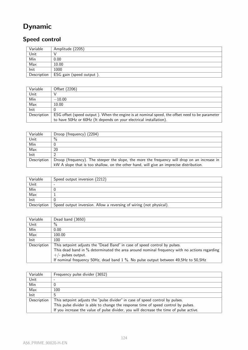
Dynamic
Speed control
Variable Amplitude (2205)Unit VMin 0.00Max 10.00Init 1000Description ESG gain (speed output ).
Variable Offset (2206)Unit VMin −10.00Max 10.00Init 0Description ESG offset (speed output ). When the engine is at nominal speed, the offset need to be parameter
to have 50Hz or 60Hz (It depends on your electrical installation).
Variable Droop (frequency) (2204)Unit %Min 0Max 20Init 2Description Droop (frequency). The steeper the slope, the more the frequency will drop on an increase in
kW A slope that is too shallow, on the other hand, will give an imprecise distribution.
Variable Speed output inversion (2212)Unit -Min 0Max 1Init 0Description Speed output inversion. Allow a reversing of wiring (not physical).
Variable Dead band (3650)Unit %Min 0.00Max 100.00Init 100Description This setpoint adjusts the ”Dead Band” in case of speed control by pulses.
This dead band in % determinated the area around nominal frequency with no actions regarding+/- pulses output.If nominal frequency 50Hz, dead band 1 %. No pulse output between 49,5Hz to 50,5Hz
Variable Frequency pulse divider (3652)Unit -Min 0Max 100Init 5Description This setpoint adjusts the ”pulse divider” in case of speed control by pulses.
This pulse divider is able to change the response time of speed control by pulses.If you increase the value of pulse divider, you will decrease the time of pulse active.
A56 PRIME 90020-H-EN124

AVR control
Variable AVR Amplitude (2251)Unit VMin 0.00Max 10.00Init 1000Description This setpoint adjusts the ”AVR amplitude”. This setpoint is used in case of analog voltage control.
This amplitude must be set to obtain a maximum and linear amplitude of 8% (correction until432Vac for 400Vac application).10% set on the product is equivalent of a correction of 1Vdc from controller to AVR.
Variable AVR Offset (2252)Unit VMin −10.00Max 10.00Init 0Description This setpoint adjusts the ”AVR offset”. This setpoint is used in case of analog voltage control.
This offset must be set to obtain the nominal voltage at the alternator, in case of no correction.10% set on the product is equivalent of a correction of 1Vdc from controller to AVR.
Variable Droop (voltage) (2250)Unit %Min 0Max 20Init 2Description Droop (voltage). The steeper the slope, the more the voltage will drop on an increase in kVAR.
A slope that is too shallow, on the other hand, will give an imprecise distribution.
Variable AVR signal output inversion (2254)Unit -Min 0Max 1Init 0Description This setpoint adjusts the ”AVR signal output inversion”.
For most of AVR brand connection :- The module increase the AVR output signal to increase the alternator voltage (Voltage externalsetpoint).- 0 to +10Vdc : increase the altenator voltage.With the variable : ”AVR signal output inversion” activated, the correction will be in oppositeaction :- 0 to +10Vdc : decrease the altenator voltage.
Variable Dead Band (3651)Unit %Min 0.00Max 100.00Init 100Description This setpoint adjusts the ”Dead Band” in case of voltage control by pulses.
This dead band in % determinated the area around nominal voltage, with no actions regarding+/- pulses output.If nominal voltage 400Vac, dead band 1 %. No pulse output between 396Vac to 404Vac
A56 PRIME 90020-H-EN125

Variable Voltage pulse divider (3653)Unit -Min 0Max 100Init 5Description This setpoint adjusts the ”pulse divider” in case of voltage control by pulses.
This pulse divider is able to change the response time of voltage control by pulses.If you increase the value of pulse divider, you will decrease the time of pulse active.
Synchronization PID
Frequency
Variable Frequency Global Gain (2900)Unit -Min 0Max 100Init 10Description The frequency synchronisation is used to match the frequency of our genset to the frequency of
the busbar or mains, in order to close its breaker in good condition. This variable sets the globalGain of frequency synchronisation PID. The global Gain is the multiplier of the proportional,integral and derivative values. A too high value will cause a pumping, a too low value will causea low reaction, We can compare it to a nervousness Gain.
Variable Frequency Proportional Gain (2901)Unit -Min 0Max 100Init 7Description Proportional value adjusts the response of the system to a static, instant error, it increases the
precision and speed. A too high setting has the effect of generating an oscillation of the system,
Variable Frequency Integral Gain (2902)Unit -Min 0Max 100Init 10Description The Integral value set the final value of the system without error. It fixes a small mistake which
is prolonged. It increases the final accuracy. A too high setting has the effect of generating anoscillation of the system
Variable Frequency Derivate Gain (2903)Unit -Min 0Max 100Init 0Description Derivate value change the increasing time to reach the set point. It increases stability and speed.
A56 PRIME 90020-H-EN126

Phase
Variable Phase Global Gain (2904)Unit -Min 0Max 100Init 10Description The phase synchronisation is used to match the phase of our genset to the phase of the busbar or
mains, in order to close its breaker in good condition. This variable sets the global Gain of phasesynchronisation PID. The global Gain is the multiplier of the proportional, integral and derivativevalues. A too high value will cause a pumping, a too low value will cause a low reaction, We cancompare it to a nervousness Gain.
Variable Phase Proportional Gain (2905)Unit -Min 0Max 100Init 30Description Proportional value to adjust the response of the system to a static, instant error, it increases the
precision and speed. A too high setting has the effect of generating an oscillation of the system,
Variable Phase Integral Gain (2906)Unit -Min 0Max 100Init 10Description The Integral value set the final value of the system without error. It fixes a small mistake which
is prolonged. It increases the final accuracy. A too high setting has the effect of generating anoscillation of the system
Variable Phase Derivate Gain (2907)Unit -Min 0Max 100Init 0Description Derivate value change the increasing time to reach the set point. It increases stability and speed.
Voltage
Variable Voltage Global Gain (2950)Unit -Min 0Max 100Init 10Description The voltage synchronisation is used to match the voltage of our genset to the voltage of the
busbar or mains, in order to close its breaker in good condition. This variable sets the global Gainof voltage synchronisation PID. The global Gain is the multiplier of the proportional, integraland derivative values. A too high value will cause a pumping, a too low value will cause a lowreaction, We can compare it to a nervousness Gain.
Variable Voltage Proportional Gain (2951)Unit -Min 0Max 100Init 20Description Proportional value to adjust the response of the system to a static, instant error, it increases the
precision and speed. A too high setting has the effect of generating an oscillation of the system,
A56 PRIME 90020-H-EN127

Variable Voltage Integral Gain (2952)Unit -Min 0Max 100Init 15Description The Integral value set the final value of the system without error. It fixes a small mistake which
is prolonged. It increases the final accuracy. A too high setting has the effect of generating anoscillation of the system
Variable Voltage Derivate Gain (2953)Unit -Min 0Max 100Init 0Description Derivate value change the increasing time to reach the set point. It increases stability and speed.
kW/kVAR PID
Active power
Variable kW Global Gain (2908)Unit -Min 0Max 100Init 10Description Load Sharing (active or reactive Power) system is used to share fairly the power needed, between
each group of installation, to the percentage of their capacity (Nominal power), This variable setsthe global Gain of KW load sharing PID. The global Gain is the multiplier of the proportional,integral and derivative values. A too high value will cause a pumping, a too low value will causea low reaction. We can compare it to a nervousness Gain.
Variable kW Proportional Gain (2909)Unit -Min 0Max 100Init 50Description Proportional value adjusts the response of the system to a static, instant error, it increases the
precision and speed. A too high setting has the effect of generating an oscillation of the system,
Variable kW Integral Gain (2910)Unit -Min 0Max 100Init 10Description The Integral value set the final value of the system without error. It fixes a small mistake which
is prolonged. It increases the final accuracy. A too high setting has the effect of generating anoscillation of the system
Variable kW Derivate Gain (2911)Unit -Min 0Max 100Init 0Description Derivate value change the increasing time to reach the set point. It increases stability and speed.
A56 PRIME 90020-H-EN128
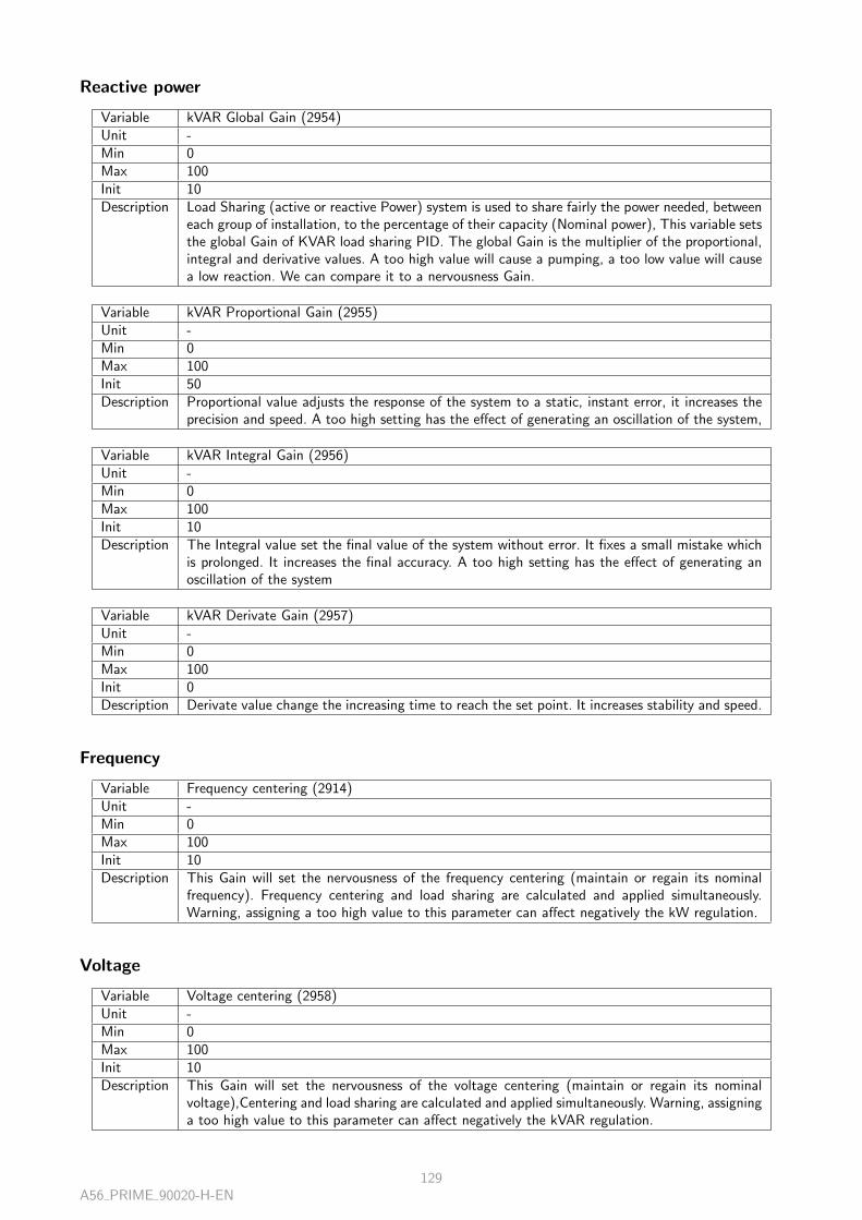
Reactive power
Variable kVAR Global Gain (2954)Unit -Min 0Max 100Init 10Description Load Sharing (active or reactive Power) system is used to share fairly the power needed, between
each group of installation, to the percentage of their capacity (Nominal power), This variable setsthe global Gain of KVAR load sharing PID. The global Gain is the multiplier of the proportional,integral and derivative values. A too high value will cause a pumping, a too low value will causea low reaction. We can compare it to a nervousness Gain.
Variable kVAR Proportional Gain (2955)Unit -Min 0Max 100Init 50Description Proportional value adjusts the response of the system to a static, instant error, it increases the
precision and speed. A too high setting has the effect of generating an oscillation of the system,
Variable kVAR Integral Gain (2956)Unit -Min 0Max 100Init 10Description The Integral value set the final value of the system without error. It fixes a small mistake which
is prolonged. It increases the final accuracy. A too high setting has the effect of generating anoscillation of the system
Variable kVAR Derivate Gain (2957)Unit -Min 0Max 100Init 0Description Derivate value change the increasing time to reach the set point. It increases stability and speed.
Frequency
Variable Frequency centering (2914)Unit -Min 0Max 100Init 10Description This Gain will set the nervousness of the frequency centering (maintain or regain its nominal
frequency). Frequency centering and load sharing are calculated and applied simultaneously.Warning, assigning a too high value to this parameter can affect negatively the kW regulation.
Voltage
Variable Voltage centering (2958)Unit -Min 0Max 100Init 10Description This Gain will set the nervousness of the voltage centering (maintain or regain its nominal
voltage),Centering and load sharing are calculated and applied simultaneously. Warning, assigninga too high value to this parameter can affect negatively the kVAR regulation.
A56 PRIME 90020-H-EN129
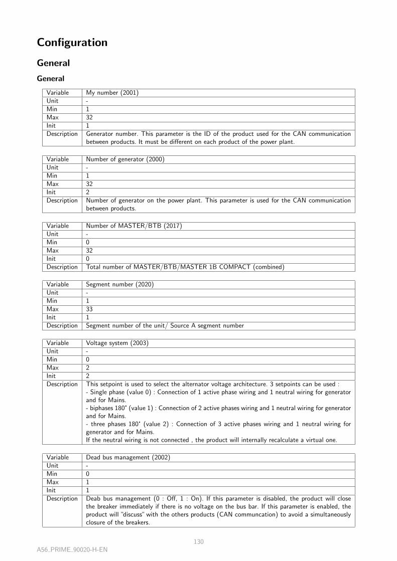
Configuration
General
General
Variable My number (2001)Unit -Min 1Max 32Init 1Description Generator number. This parameter is the ID of the product used for the CAN communication
between products. It must be different on each product of the power plant.
Variable Number of generator (2000)Unit -Min 1Max 32Init 2Description Number of generator on the power plant. This parameter is used for the CAN communication
between products.
Variable Number of MASTER/BTB (2017)Unit -Min 0Max 32Init 0Description Total number of MASTER/BTB/MASTER 1B COMPACT (combined)
Variable Segment number (2020)Unit -Min 1Max 33Init 1Description Segment number of the unit/ Source A segment number
Variable Voltage system (2003)Unit -Min 0Max 2Init 2Description This setpoint is used to select the alternator voltage architecture. 3 setpoints can be used :
- Single phase (value 0) : Connection of 1 active phase wiring and 1 neutral wiring for generatorand for Mains.- biphases 180° (value 1) : Connection of 2 active phases wiring and 1 neutral wiring for generatorand for Mains.- three phases 180° (value 2) : Connection of 3 active phases wiring and 1 neutral wiring forgenerator and for Mains.If the neutral wiring is not connected , the product will internally recalculate a virtual one.
Variable Dead bus management (2002)Unit -Min 0Max 1Init 1Description Deab bus management (0 : Off, 1 : On). If this parameter is disabled, the product will close
the breaker immediately if there is no voltage on the bus bar. If this parameter is enabled, theproduct will ”discuss” with the others products (CAN communcation) to avoid a simultaneouslyclosure of the breakers.
A56 PRIME 90020-H-EN130

Variable Inhib. remote start MASTER (2018)Unit -Min 0Max 1Init 0Description Allows a unit to ignore the MASTER’s commands in the same segment
Mode
Variable Power up in mode (2012)Unit -Min 0Max 2Init 0Description This setpoint is used to select the mode of the product when the power supply is applied. 3
setpoints can be used :- Manual (Value 0) : The product will switch-on on Manual mode- Test (Value 1) : The product will switch-on on Test mode- Auto (Value 2) : The product will switch-on on Auto mode
Variable Test mode (2014)Unit -Min 0Max 2Init 0Description This setpoint is used to select the actions for test mode on the product. 3 setpoints can be used :
- On load (Value 0) : The generator will start as auto mode, and will manage sequence to closethe breaker and manage the load.- Off load (Value 1) : The generator will start as auto mode, will manage sequences but will notclose the generator breaker.- On load with timer (Value 2) :The generator will start as auto mode, will run without loadduring this timer and after to close the breaker to manage the load.
Variable Test active timer on (2015)Unit -Min 0Max 1Init 0Description This setpoint is used to activate a timer function for test mode. During this timer, the test mode
is activated. At the end of this timer, the generator will stop, and product will be forced on automode.
Variable Test active timer (2016)Unit sMin 0.0Max 6553.5Init 6000Description This setpoint is a timer in seconds.During this timer, and if setpoint E2015 is ON (Test active
timer on) the test mode is activated. At the end of this timer, the generator will stop, andproduct will be forced on auto mode.
A56 PRIME 90020-H-EN131
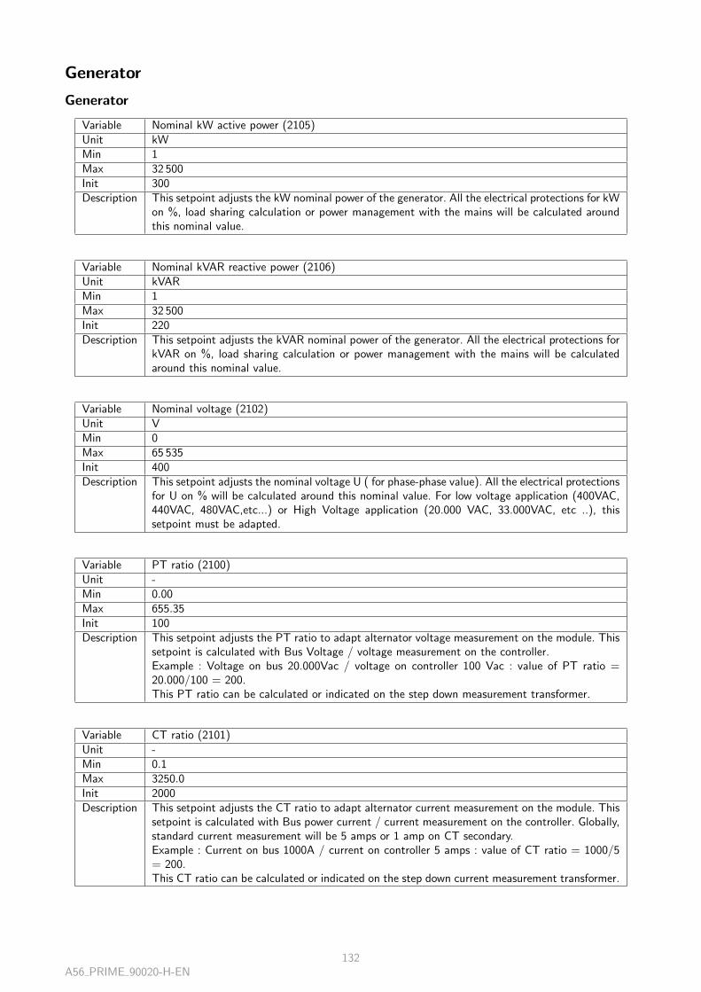
Generator
Generator
Variable Nominal kW active power (2105)Unit kWMin 1Max 32 500Init 300Description This setpoint adjusts the kW nominal power of the generator. All the electrical protections for kW
on %, load sharing calculation or power management with the mains will be calculated aroundthis nominal value.
Variable Nominal kVAR reactive power (2106)Unit kVARMin 1Max 32 500Init 220Description This setpoint adjusts the kVAR nominal power of the generator. All the electrical protections for
kVAR on %, load sharing calculation or power management with the mains will be calculatedaround this nominal value.
Variable Nominal voltage (2102)Unit VMin 0Max 65 535Init 400Description This setpoint adjusts the nominal voltage U ( for phase-phase value). All the electrical protections
for U on % will be calculated around this nominal value. For low voltage application (400VAC,440VAC, 480VAC,etc...) or High Voltage application (20.000 VAC, 33.000VAC, etc ..), thissetpoint must be adapted.
Variable PT ratio (2100)Unit -Min 0.00Max 655.35Init 100Description This setpoint adjusts the PT ratio to adapt alternator voltage measurement on the module. This
setpoint is calculated with Bus Voltage / voltage measurement on the controller.Example : Voltage on bus 20.000Vac / voltage on controller 100 Vac : value of PT ratio =20.000/100 = 200.This PT ratio can be calculated or indicated on the step down measurement transformer.
Variable CT ratio (2101)Unit -Min 0.1Max 3250.0Init 2000Description This setpoint adjusts the CT ratio to adapt alternator current measurement on the module. This
setpoint is calculated with Bus power current / current measurement on the controller. Globally,standard current measurement will be 5 amps or 1 amp on CT secondary.Example : Current on bus 1000A / current on controller 5 amps : value of CT ratio = 1000/5= 200.This CT ratio can be calculated or indicated on the step down current measurement transformer.
A56 PRIME 90020-H-EN132
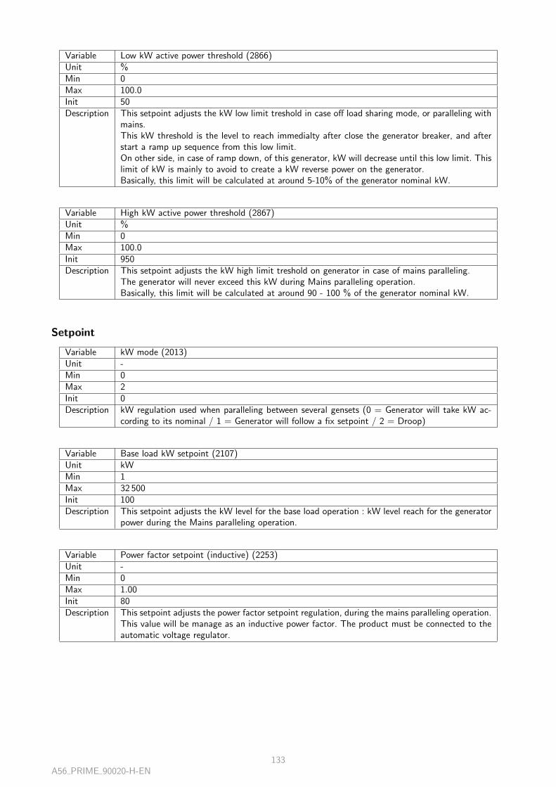
Variable Low kW active power threshold (2866)Unit %Min 0Max 100.0Init 50Description This setpoint adjusts the kW low limit treshold in case off load sharing mode, or paralleling with
mains.This kW threshold is the level to reach immedialty after close the generator breaker, and afterstart a ramp up sequence from this low limit.On other side, in case of ramp down, of this generator, kW will decrease until this low limit. Thislimit of kW is mainly to avoid to create a kW reverse power on the generator.Basically, this limit will be calculated at around 5-10% of the generator nominal kW.
Variable High kW active power threshold (2867)Unit %Min 0Max 100.0Init 950Description This setpoint adjusts the kW high limit treshold on generator in case of mains paralleling.
The generator will never exceed this kW during Mains paralleling operation.Basically, this limit will be calculated at around 90 - 100 % of the generator nominal kW.
Setpoint
Variable kW mode (2013)Unit -Min 0Max 2Init 0Description kW regulation used when paralleling between several gensets (0 = Generator will take kW ac-
cording to its nominal / 1 = Generator will follow a fix setpoint / 2 = Droop)
Variable Base load kW setpoint (2107)Unit kWMin 1Max 32 500Init 100Description This setpoint adjusts the kW level for the base load operation : kW level reach for the generator
power during the Mains paralleling operation.
Variable Power factor setpoint (inductive) (2253)Unit -Min 0Max 1.00Init 80Description This setpoint adjusts the power factor setpoint regulation, during the mains paralleling operation.
This value will be manage as an inductive power factor. The product must be connected to theautomatic voltage regulator.
A56 PRIME 90020-H-EN133
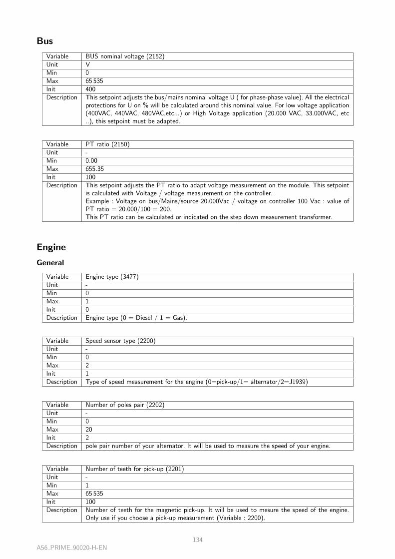
Bus
Variable BUS nominal voltage (2152)Unit VMin 0Max 65 535Init 400Description This setpoint adjusts the bus/mains nominal voltage U ( for phase-phase value). All the electrical
protections for U on % will be calculated around this nominal value. For low voltage application(400VAC, 440VAC, 480VAC,etc...) or High Voltage application (20.000 VAC, 33.000VAC, etc..), this setpoint must be adapted.
Variable PT ratio (2150)Unit -Min 0.00Max 655.35Init 100Description This setpoint adjusts the PT ratio to adapt voltage measurement on the module. This setpoint
is calculated with Voltage / voltage measurement on the controller.Example : Voltage on bus/Mains/source 20.000Vac / voltage on controller 100 Vac : value ofPT ratio = 20.000/100 = 200.This PT ratio can be calculated or indicated on the step down measurement transformer.
Engine
General
Variable Engine type (3477)Unit -Min 0Max 1Init 0Description Engine type (0 = Diesel / 1 = Gas).
Variable Speed sensor type (2200)Unit -Min 0Max 2Init 1Description Type of speed measurement for the engine (0=pick-up/1= alternator/2=J1939)
Variable Number of poles pair (2202)Unit -Min 0Max 20Init 2Description pole pair number of your alternator. It will be used to measure the speed of your engine.
Variable Number of teeth for pick-up (2201)Unit -Min 1Max 65 535Init 100Description Number of teeth for the magnetic pick-up. It will be used to mesure the speed of the engine.
Only use if you choose a pick-up measurement (Variable : 2200).
A56 PRIME 90020-H-EN134
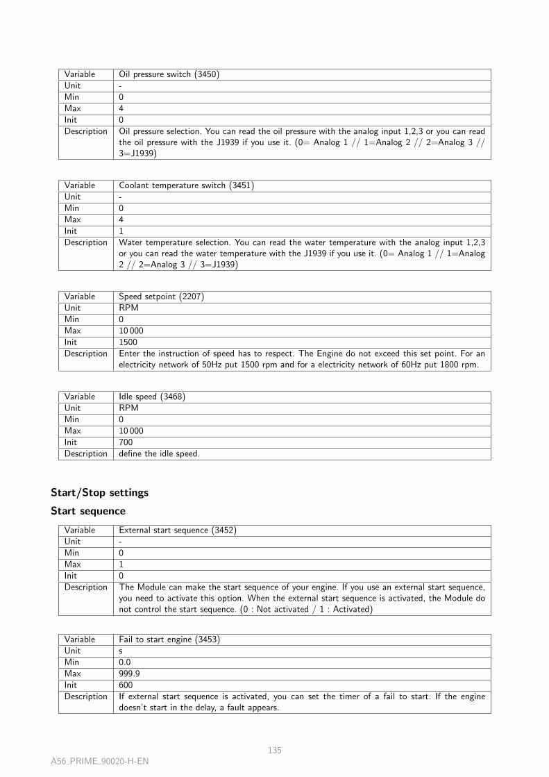
Variable Oil pressure switch (3450)Unit -Min 0Max 4Init 0Description Oil pressure selection. You can read the oil pressure with the analog input 1,2,3 or you can read
the oil pressure with the J1939 if you use it. (0= Analog 1 // 1=Analog 2 // 2=Analog 3 //3=J1939)
Variable Coolant temperature switch (3451)Unit -Min 0Max 4Init 1Description Water temperature selection. You can read the water temperature with the analog input 1,2,3
or you can read the water temperature with the J1939 if you use it. (0= Analog 1 // 1=Analog2 // 2=Analog 3 // 3=J1939)
Variable Speed setpoint (2207)Unit RPMMin 0Max 10 000Init 1500Description Enter the instruction of speed has to respect. The Engine do not exceed this set point. For an
electricity network of 50Hz put 1500 rpm and for a electricity network of 60Hz put 1800 rpm.
Variable Idle speed (3468)Unit RPMMin 0Max 10 000Init 700Description define the idle speed.
Start/Stop settings
Start sequence
Variable External start sequence (3452)Unit -Min 0Max 1Init 0Description The Module can make the start sequence of your engine. If you use an external start sequence,
you need to activate this option. When the external start sequence is activated, the Module donot control the start sequence. (0 : Not activated / 1 : Activated)
Variable Fail to start engine (3453)Unit sMin 0.0Max 999.9Init 600Description If external start sequence is activated, you can set the timer of a fail to start. If the engine
doesn’t start in the delay, a fault appears.
A56 PRIME 90020-H-EN135

Variable Engine not ready (3454)Unit sMin 0.0Max 999.9Init 100Description Maximum time to start (internal sequence : maximum prelubrification/external sequence : GE
not ready)
Variable Warm up selection (3479)Unit -Min 0Max 1Init 0Description When starting the engin,choice to select the warm up speed (0 = Nominal speed / 1 = Idle
speed) .
Check before start
Variable Preheating coolant temperature threshold (3474)Unit °CMin −3276.7Max 3276.7Init 0Description Minimum Preheating coolant temperature threshold before engine start. (0 = no check)
Variable Minimum oil prelubrication threshold (3473)Unit mBarMin 0Max 6553.5Init 0Description Minimum oil prelubrification threshold before engine start. (0 = no check)
Variable Cooling fan activation threshold (3475)Unit °CMin −32 767Max 32 767Init 40Description The cooling fan activates when the coolant temperature is above this setting.
Stop sequence
Variable Cooling speed selection (3476)Unit -Min 0Max 1Init 0Description Before the complete stop of the engine, the engine make a cooling speed. Select the cooling speed
adapted with your installation : nominal speed (variable 2207) or idle speed (variable 3468). ( 0= Nominal speed / 1 = Idle speed).
A56 PRIME 90020-H-EN136
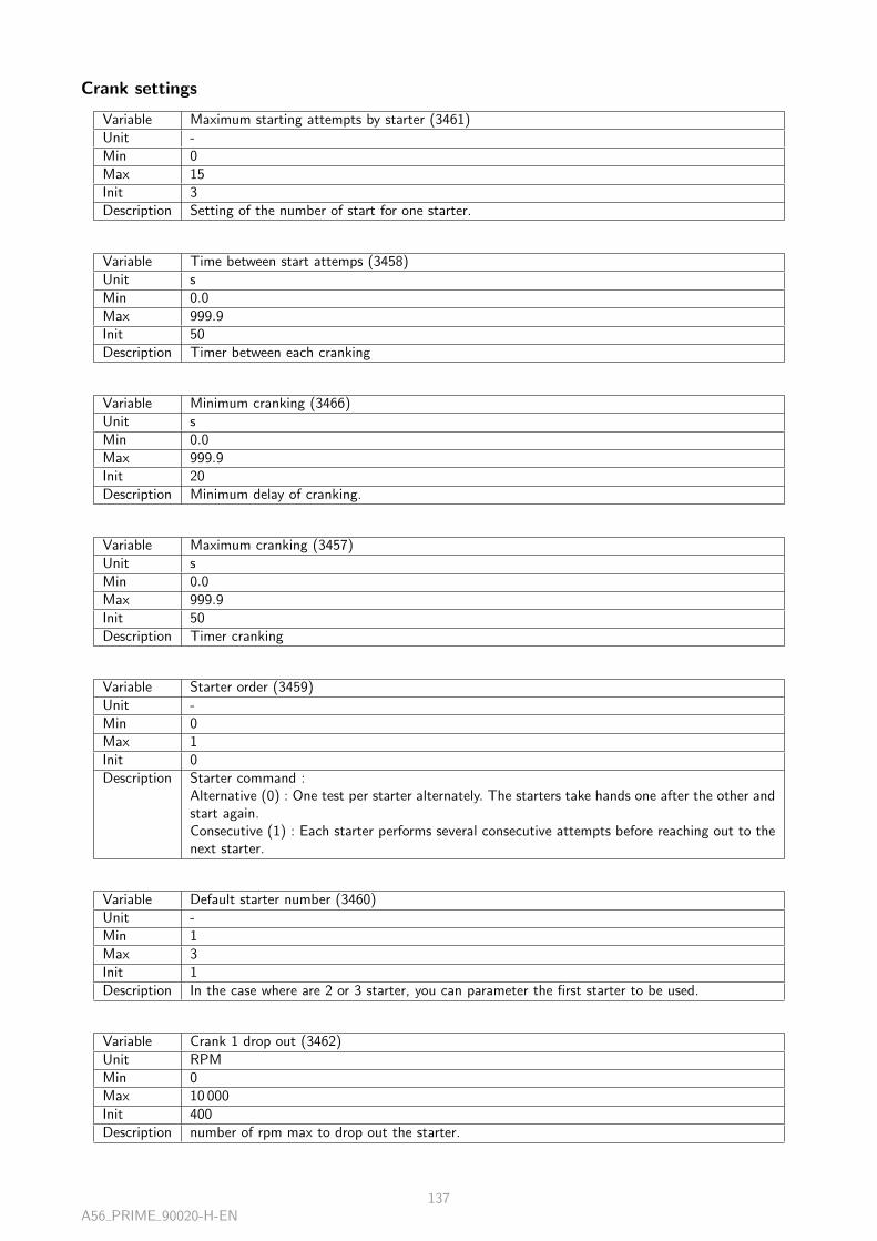
Crank settings
Variable Maximum starting attempts by starter (3461)Unit -Min 0Max 15Init 3Description Setting of the number of start for one starter.
Variable Time between start attemps (3458)Unit sMin 0.0Max 999.9Init 50Description Timer between each cranking
Variable Minimum cranking (3466)Unit sMin 0.0Max 999.9Init 20Description Minimum delay of cranking.
Variable Maximum cranking (3457)Unit sMin 0.0Max 999.9Init 50Description Timer cranking
Variable Starter order (3459)Unit -Min 0Max 1Init 0Description Starter command :
Alternative (0) : One test per starter alternately. The starters take hands one after the other andstart again.Consecutive (1) : Each starter performs several consecutive attempts before reaching out to thenext starter.
Variable Default starter number (3460)Unit -Min 1Max 3Init 1Description In the case where are 2 or 3 starter, you can parameter the first starter to be used.
Variable Crank 1 drop out (3462)Unit RPMMin 0Max 10 000Init 400Description number of rpm max to drop out the starter.
A56 PRIME 90020-H-EN137

Variable Crank 2 drop out (3463)Unit RPMMin 0Max 10 000Init 400Description Crank 2 drop out
Variable Crank 3 drop out (3464)Unit RPMMin 0Max 10 000Init 400Description Crank 3 drop out
AVR excitation
Variable Excitation (2050)Unit -Min 0Max 1Init 0Description This setpoint is used to select the synchronization mode. 2 setpoints can be used :
- Dynamic (value 0) : The synchronization will be manage during on speed condition.- Static paralleling (value 1) : The synchronization is manage during engine start and withoutexcitation condition.
Variable Excit. speed (2053)Unit %Min −200.0Max 200.0Init 900Description Percentage of speed to allow excitation for static paralleling. For a PRIME module, the threshold
need to be the same with all module PRIME.
Variable Excit. volt. (2054)Unit %Min −200.0Max 200.0Init 200Description Percentage of voltage to allow closing breaker in static paralleling. For a PRIME module, the
threshold need to be the same with all module PRIME.
Variable Voltage stabilisation (only static paralleling) (2056)Unit sMin 0.0Max 999.9Init 50Description Delay to wait voltage stabilisation after static paralleling
J1939
Variable Manufacturer (3100)Unit -Min 0Max 32Init 0Description Choose the Manufacturer of you engine. If the manufacturer is not in the list, choose ”Generic”.
A56 PRIME 90020-H-EN138

Variable ECU type (3101)Unit -Min 0Max 32Init 0Description Choose the model of your ECU. If your ECU is not in the list, choose ”Generic”.
Inputs
Digital inputs
Variable Input 1 (Customisable) (250)Unit -Min 0Max 1Init -Description Digital input 1
Variable Input 2 (Customisable) (251)Unit -Min 0Max 1Init -Description Digital input 2
Variable Input 3 (Customisable) (252)Unit -Min 0Max 1Init -Description Digital input 3
Variable Input 4 (Customisable) (253)Unit -Min 0Max 1Init -Description Digital input 4
Variable Input 5 (Customisable) (254)Unit -Min 0Max 1Init -Description Digital input 5
Variable Input 6 (Customisable) (255)Unit -Min 0Max 1Init -Description Digital input 6
A56 PRIME 90020-H-EN139

Variable Input 7 (Customisable) (256)Unit -Min 0Max 1Init -Description Digital input 7
Variable Input 8 (Customisable) (257)Unit -Min 0Max 1Init -Description Digital input 8
Variable Input 9 (Customisable) (258)Unit -Min 0Max 1Init -Description Digital input 9
Hysteresis DI
Hysteresis DI 1
Variable Hysteresis 1 enable for DI (2769)Unit -Min 0Max 1Init 0Description Enable hysteresis 1 on digital inputs functions
Variable Timer (2777)Unit sMin 0.0Max 999.9Init 0Description Timer at activation on digital input of Hysteresis 1
Variable Direction (2785)Unit -Min 0Max 1Init 0Description Direction Hysteresis 1 : 0 = Set on low thresh. - Reset on high thresh. / 1 = Set on high thresh.
- Reset on low thresh.
Hysteresis DI 2
Variable Hysteresis 2 enable for DI (2770)Unit -Min 0Max 1Init 0Description Enable hysteresis 2 on digital inputs functions
A56 PRIME 90020-H-EN140

Variable Timer (2778)Unit sMin 0.0Max 999.9Init 0Description Timer at activation on digital input of Hysteresis 2
Variable Direction (2786)Unit -Min 0Max 1Init 0Description Direction Hysteresis 2 : 0 = Set on low thresh. - Reset on high thresh. / 1 = Set on high thresh.
- Reset on low thresh.
Hysteresis DI 3
Variable Hysteresis 3 enable for DI (2771)Unit -Min 0Max 1Init 0Description Enable hysteresis 3 on digital inputs functions
Variable Timer (2779)Unit sMin 0.0Max 999.9Init 0Description Timer at activation on digital input of Hysteresis 3
Variable Direction (2787)Unit -Min 0Max 1Init 0Description Direction Hysteresis 3 : 0 = Set on low thresh. - Reset on high thresh. / 1 = Set on high thresh.
- Reset on low thresh.
Hysteresis DI 4
Variable Hysteresis 4 enable for DI (2772)Unit -Min 0Max 1Init 0Description Enable hysteresis 4 on digital inputs functions
Variable Timer (2780)Unit sMin 0.0Max 999.9Init 0Description Timer at activation on digital input of Hysteresis 4
A56 PRIME 90020-H-EN141

Variable Direction (2788)Unit -Min 0Max 1Init 0Description Direction Hysteresis 4 : 0 = Set on low thresh. - Reset on high thresh. / 1 = Set on high thresh.
- Reset on low thresh.
Hysteresis DI 5
Variable Hysteresis 5 enable for DI (2773)Unit -Min 0Max 1Init 0Description Enable hysteresis 5 on digital inputs functions
Variable Timer (2781)Unit sMin 0.0Max 999.9Init 0Description Timer at activation on digital input of Hysteresis 5
Variable Direction (2789)Unit -Min 0Max 1Init 0Description Direction Hysteresis 5 : 0 = Set on low thresh. - Reset on high thresh. / 1 = Set on high thresh.
- Reset on low thresh.
Hysteresis DI 6
Variable Hysteresis 6 enable for DI (2774)Unit -Min 0Max 1Init 0Description Enable hysteresis 6 on digital inputs functions
Variable Timer (2782)Unit sMin 0.0Max 999.9Init 0Description Timer at activation on digital input of Hysteresis 6
Variable Direction (2790)Unit -Min 0Max 1Init 0Description Direction Hysteresis 6 : 0 = Set on low thresh. - Reset on high thresh. / 1 = Set on high thresh.
- Reset on low thresh.
A56 PRIME 90020-H-EN142

Hysteresis DI 7
Variable Hysteresis 7 enable for DI (2775)Unit -Min 0Max 1Init 0Description Enable hysteresis 7 on digital inputs functions
Variable Timer (2783)Unit sMin 0.0Max 999.9Init 0Description Timer at activation on digital input of Hysteresis 7
Variable Direction (2791)Unit -Min 0Max 1Init 0Description Direction Hysteresis 7 : 0 = Set on low thresh. - Reset on high thresh. / 1 = Set on high thresh.
- Reset on low thresh.
Hysteresis DI 8
Variable Hysteresis 8 enable for DI (2776)Unit -Min 0Max 1Init 0Description Enable hysteresis 8 on digital inputs functions
Variable Timer (2784)Unit sMin 0.0Max 999.9Init 0Description Timer at activation on digital input of Hysteresis 8
Variable Direction (2792)Unit -Min 0Max 1Init 0Description Direction Hysteresis 8 : 0 = Set on low thresh. - Reset on high thresh. / 1 = Set on high thresh.
- Reset on low thresh.
Analog inputs
Variable Analog 1 (Customisable) (150)Unit mBarMin −3276.7Max 3276.7Init -Description Analog 1 measure
A56 PRIME 90020-H-EN143
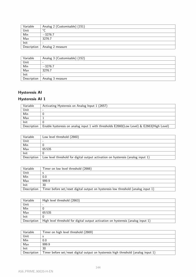
Variable Analog 2 (Customisable) (151)Unit °CMin −3276.7Max 3276.7Init -Description Analog 2 measure
Variable Analog 3 (Customisable) (152)Unit -Min −3276.7Max 3276.7Init -Description Analog 3 measure
Hysteresis AI
Hysteresis AI 1
Variable Activating Hysteresis on Analog Input 1 (2657)Unit -Min 0Max 1Init 0Description Enable hysteresis on analog input 1 with thresholds E2660(Low Level) & E2663(High Level)
Variable Low level threshold (2660)Unit -Min 0Max 65 535Init 0Description Low level threshold for digital output activation on hysteresis (analog input 1)
Variable Timer on low level threshold (2666)Unit sMin 0.0Max 999.9Init 30Description Timer before set/reset digital output on hysteresis low threshold (analog input 1)
Variable High level threshold (2663)Unit -Min 0Max 65 535Init 0Description High level threshold for digital output activation on hysteresis (analog input 1)
Variable Timer on high level threshold (2669)Unit sMin 0.0Max 999.9Init 30Description Timer before set/reset digital output on hysteresis high threshold (analog input 1)
A56 PRIME 90020-H-EN144

Variable Hysteresis Direction on Analog Input 1 (2672)Unit -Min 0Max 1Init 0Description Hysteresis Direction on Analog Input 1 (0 : Set on low thresh. - Reset on high thresh. / 1 : Set
on high thresh. - Reset on low thresh)
Hysteresis AI 2
Variable Activating Hysteresis on Analog Input 2 (2658)Unit -Min 0Max 1Init 0Description Enable hysteresis on analog input 2 with thresholds E2661(Low Level) & E2664(High Level)
Variable Low level threshold (2661)Unit -Min 0Max 65 535Init 0Description Low level threshold for digital output activation on hysteresis (analog input 2)
Variable Timer on low level threshold (2667)Unit sMin 0.0Max 999.9Init 30Description Timer before set/reset digital output on hysteresis low threshold (analog input 2)
Variable High level threshold (2664)Unit -Min 0Max 65 535Init 0Description High level threshold for digital output activation on hysteresis (analog input 2)
Variable Timer on high level threshold (2670)Unit sMin 0.0Max 999.9Init 30Description Timer before set/reset digital output on hysteresis high threshold (analog input 2)
Variable Hysteresis Direction on Analog Input 2 (2673)Unit -Min 0Max 1Init 0Description Hysteresis Direction on Analog Input 2 (0 : Set on low thresh. - Reset on high thresh. / 1 : Set
on high thresh. - Reset on low thresh)
A56 PRIME 90020-H-EN145

Hysteresis AI 3
Variable Activating Hysteresis on Analog Input 3 (2659)Unit -Min 0Max 1Init 0Description Enable hysteresis on analog input 3 with thresholds E2662(Low Level) & E2665(High Level)
Variable Low level threshold (2662)Unit -Min 0Max 65 535Init 0Description Low level threshold for digital output activation on hysteresis (analog input 3)
Variable Timer on low level threshold (2668)Unit sMin 0.0Max 999.9Init 30Description Timer before set/reset digital output on hysteresis low threshold (analog input 3)
Variable High level threshold (2665)Unit -Min 0Max 65 535Init 0Description High level threshold for digital output activation on hysteresis (analog input 3)
Variable Timer on high level threshold (2671)Unit sMin 0.0Max 999.9Init 30Description Timer before set/reset digital output on hysteresis high threshold (analog input 3)
Variable Hysteresis Direction on Analog Input 3 (2674)Unit -Min 0Max 1Init 0Description Hysteresis Direction on Analog Input 3 (0 : Set on low thresh. - Reset on high thresh. / 1 : Set
on high thresh. - Reset on low thresh)
Outputs
Digital/relays outputs
Digital outputs
Variable Status Digital Output 1 (4350)Unit -Min 0Max 1Init -Description Real time displayed status of Digital Output 1
A56 PRIME 90020-H-EN146

Variable Status Digital Output 2 (4351)Unit -Min 0Max 1Init -Description Real time displayed status of Digital Output 2
Variable Status Digital Output 3 (4352)Unit -Min 0Max 1Init -Description Real time displayed status of Digital Output 3
Variable Status Digital Output 4 (4353)Unit -Min 0Max 1Init -Description Real time displayed status of Digital Output 4
Variable Status Digital Output 5 (4354)Unit -Min 0Max 1Init -Description Real time displayed status of Digital Output 5
Variable Status Digital Output 6 (4355)Unit -Min 0Max 1Init -Description Real time displayed status of Digital Output 6
Relay outputs
Variable Status Relay Output 1 (4356)Unit -Min 0Max 1Init -Description Real time displayed status of Relay Output 1
Variable Status Relay Output 2 (4357)Unit -Min 0Max 1Init -Description Real time displayed status of Relay Output 2
A56 PRIME 90020-H-EN147

Generator breaker
Control
Variable Generator circuit breaker control type (2300)Unit -Min 0Max 5Init 1Description Control type of the relay for the genset circuit breaker of the genset (pulse, hold, coil. . .)
Pulse
Variable Gen CB control Pulse length (2301)Unit sMin 0.0Max 999.9Init 25Description Generator circuit breaker pulse length
Variable Undervoltage coil hold time GCB (2302)Unit sMin 0.0Max 999.9Init 10Description Generator circuit breaker : timer of the negative impulsion when low voltage coil
Variable Undervoltage coil security timer GCB (2303)Unit sMin 0.0Max 999.9Init 2Description Generator circuit breaker : delay between 2 attempts when low voltage coil negative pulse is used
Generator protections
Over/under frequency
Over frequency
Variable Over frequency threshold (2400)Unit %Min 0.0Max 200.0Init 1050Description Over-frequency Generator Protection Threshold
Variable Over frequency timer (2401)Unit sMin 0.0Max 999.9Init 300Description Timer acceptance before protection activation when Generator Frequency has reached the over-
frequency protection threshold
A56 PRIME 90020-H-EN148

Variable Over frequency control (2402)Unit -Min 0Max 7Init 4Description Control selection when Generator Over-frequency protection become active.The selections are
the following :- Unused : no action.- Generator electrical fault : The protection opens the generator breaker and tries to re-synchronize again. Count of attemps set by variable 2807.- Mains electrical fault : The protection opens the Mains breaker.- Alarm : Notice as alarm on front panel.- Fault (soft shutdown) : Generator breaker opens allowing the engine to cool down off load forthe duration of the cool down timer, then stop.- Security (hard shutdown) : Generator breaker opens and engine stops immediately withoutcooling down : ”serious fault” shows as information.- +Help means the faulty generator will ask another genset to start through inter-module Buscanto replace it.
Under frequency
Variable Under frequency threshold (2403)Unit %Min 0.0Max 200.0Init 900Description Under-frequency Generator Protection Threshold
Variable Under frequency timer (2404)Unit sMin 0.0Max 999.9Init 100Description Timer acceptance before protection activation when Generator Frequency has reached the Under-
frequency protection threshold
Variable Under frequency control (2405)Unit -Min 0Max 7Init 4Description Control selection when Generator Under-frequency protection become active.The selections are
the following :- Unused : no action.- Generator electrical fault : The protection opens the generator breaker and tries to re-synchronize again. Count of attemps set by variable 2807.- Mains electrical fault : The protection opens the Mains breaker.- Alarm : Notice as alarm on front panel.- Fault (soft shutdown) : Generator breaker opens allowing the engine to cool down off load forthe duration of the cool down timer, then stop.- Security (hard shutdown) : Generator breaker opens and engine stops immediately withoutcooling down : ”serious fault” shows as information.- +Help means the faulty generator will ask another genset to start through inter-module Buscanto replace it.
A56 PRIME 90020-H-EN149

Over frequency 2
Variable Over frequency threshold 2 (2436)Unit %Min 0.0Max 200.0Init 1100Description Over-frequency Generator Protection Threshold 2
Variable Over frequency timer 2 (2437)Unit sMin 0.0Max 999.9Init 100Description Timer 2 acceptance before protection activation when Generator Frequency has reached the
over-frequency protection threshold
Variable Over frequency control 2 (2438)Unit -Min 0Max 7Init 0Description Control 2 selection when Generator Over-frequency protection become active.The selections are
the following :- Unused : no action.- Generator electrical fault : The protection opens the generator breaker and tries to re-synchronize again. Count of attemps set by variable 2807.- Mains electrical fault : The protection opens the Mains breaker.- Alarm : Notice as alarm on front panel.- Fault (soft shutdown) : Generator breaker opens allowing the engine to cool down off load forthe duration of the cool down timer, then stop.- Security (hard shutdown) : Generator breaker opens and engine stops immediately withoutcooling down : ”serious fault” shows as information.- +Help means the faulty generator will ask another genset to start through inter-module Buscanto replace it.
Under frequency 2
Variable Under frequency threshold 2 (2439)Unit %Min 0.0Max 200.0Init 900Description Under-frequency Generator Protection Threshold 2
Variable Under frequency timer 2 (2440)Unit sMin 0.0Max 999.9Init 100Description Timer 2 acceptance before protection activation when Generator Frequency has reached the
Under-frequency protection threshold
A56 PRIME 90020-H-EN150

Variable Under frequency control 2 (2441)Unit -Min 0Max 7Init 0Description Control 2 selection when Generator Under-frequency protection become active.The selections are
the following :- Unused : no action.- Generator electrical fault : The protection opens the generator breaker and tries to re-synchronize again. Count of attemps set by variable 2807.- Mains electrical fault : The protection opens the Mains breaker.- Alarm : Notice as alarm on front panel.- Fault (soft shutdown) : Generator breaker opens allowing the engine to cool down off load forthe duration of the cool down timer, then stop.- Security (hard shutdown) : Generator breaker opens and engine stops immediately withoutcooling down : ”serious fault” shows as information.- +Help means the faulty generator will ask another genset to start through inter-module Buscanto replace it.
Over/under voltage
Over voltage
Variable Over voltage threshold (2406)Unit %Min 0.0Max 200.0Init 1100Description Over-voltage Generator Protection Threshold
Variable Over voltage timer (2407)Unit sMin 0.0Max 999.9Init 100Description Timer acceptance before protection activation when Generator voltage has reached the over-
voltage protection threshold
Variable Over voltage control (2408)Unit -Min 0Max 7Init 4Description Control selection when Generator Over-voltage protection become active.The selections are the
following :- Unused : no action.- Generator electrical fault : The protection opens the generator breaker and tries to re-synchronize again. Count of attemps set by variable 2807.- Mains electrical fault : The protection opens the Mains breaker.- Alarm : Notice as alarm on front panel.- Fault (soft shutdown) : Generator breaker opens allowing the engine to cool down off load forthe duration of the cool down timer, then stop.- Security (hard shutdown) : Generator breaker opens and engine stops immediately withoutcooling down : ”serious fault” shows as information.- +Help means the faulty generator will ask another genset to start through inter-module Buscanto replace it.
A56 PRIME 90020-H-EN151

Under voltage
Variable Under voltage threshold (2409)Unit %Min 0.0Max 200.0Init 900Description Under-voltage Generator Protection Threshold
Variable Under voltage timer (2410)Unit sMin 0.0Max 999.9Init 200Description Timer acceptance before protection activation when Generator voltage has reached the Under-
voltage protection threshold
Variable Under voltage control (2411)Unit -Min 0Max 7Init 4Description Control selection when Generator Under-voltage protection become active.The selections are the
following :- Unused : no action.- Generator electrical fault : The protection opens the generator breaker and tries to re-synchronize again. Count of attemps set by variable 2807.- Mains electrical fault : The protection opens the Mains breaker.- Alarm : Notice as alarm on front panel.- Fault (soft shutdown) : Generator breaker opens allowing the engine to cool down off load forthe duration of the cool down timer, then stop.- Security (hard shutdown) : Generator breaker opens and engine stops immediately withoutcooling down : ”serious fault” shows as information.- +Help means the faulty generator will ask another genset to start through inter-module Buscanto replace it.
Over voltage 2
Variable Over voltage threshold 2 (2442)Unit %Min 0.0Max 200.0Init 1100Description Over-voltage Generator Protection Threshold 2
Variable Over voltage timer 2 (2443)Unit sMin 0.0Max 999.9Init 100Description Timer 2 acceptance before protection activation when Generator voltage has reached the over-
voltage protection threshold
A56 PRIME 90020-H-EN152
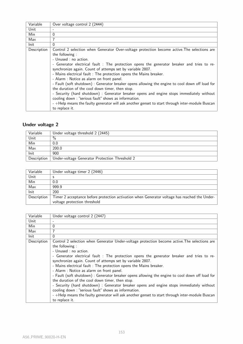
Variable Over voltage control 2 (2444)Unit -Min 0Max 7Init 0Description Control 2 selection when Generator Over-voltage protection become active.The selections are
the following :- Unused : no action.- Generator electrical fault : The protection opens the generator breaker and tries to re-synchronize again. Count of attemps set by variable 2807.- Mains electrical fault : The protection opens the Mains breaker.- Alarm : Notice as alarm on front panel.- Fault (soft shutdown) : Generator breaker opens allowing the engine to cool down off load forthe duration of the cool down timer, then stop.- Security (hard shutdown) : Generator breaker opens and engine stops immediately withoutcooling down : ”serious fault” shows as information.- +Help means the faulty generator will ask another genset to start through inter-module Buscanto replace it.
Under voltage 2
Variable Under voltage threshold 2 (2445)Unit %Min 0.0Max 200.0Init 900Description Under-voltage Generator Protection Threshold 2
Variable Under voltage timer 2 (2446)Unit sMin 0.0Max 999.9Init 200Description Timer 2 acceptance before protection activation when Generator voltage has reached the Under-
voltage protection threshold
Variable Under voltage control 2 (2447)Unit -Min 0Max 7Init 0Description Control 2 selection when Generator Under-voltage protection become active.The selections are
the following :- Unused : no action.- Generator electrical fault : The protection opens the generator breaker and tries to re-synchronize again. Count of attemps set by variable 2807.- Mains electrical fault : The protection opens the Mains breaker.- Alarm : Notice as alarm on front panel.- Fault (soft shutdown) : Generator breaker opens allowing the engine to cool down off load forthe duration of the cool down timer, then stop.- Security (hard shutdown) : Generator breaker opens and engine stops immediately withoutcooling down : ”serious fault” shows as information.- +Help means the faulty generator will ask another genset to start through inter-module Buscanto replace it.
A56 PRIME 90020-H-EN153

Over current/neutral
Over current
Variable Over current threshold (2430)Unit AMin 0Max 65 535Init 500Description Over-Current Generator Protection Threshold
Variable Over current timer (2431)Unit sMin 0.0Max 999.9Init 30Description Timer acceptance before protection activation when Generator Current has reached the over-
Current protection threshold
Variable Over current control (2432)Unit -Min 0Max 7Init 0Description Control selection when Generator Over-Current protection become active.The selections are the
following :- Unused : no action.- Generator electrical fault : The protection opens the generator breaker and tries to re-synchronize again. Count of attemps set by variable 2807.- Mains electrical fault : The protection opens the Mains breaker.- Alarm : Notice as alarm on front panel.- Fault (soft shutdown) : Generator breaker opens allowing the engine to cool down off load forthe duration of the cool down timer, then stop.- Security (hard shutdown) : Generator breaker opens and engine stops immediately withoutcooling down : ”serious fault” shows as information.- +Help means the faulty generator will ask another genset to start through inter-module Buscanto replace it.
Neutral current
Variable Neutral current threshold (2433)Unit AMin 0Max 65 535Init 300Description Over Neutral Current Generator Protection Threshold
Variable Neutral current timer (2434)Unit sMin 0.0Max 999.9Init 1200Description Timer acceptance before protection activation when Generator Neutral Current has reached the
Over Neutral Current protection threshold
A56 PRIME 90020-H-EN154

Variable Neutral current control (2435)Unit -Min 0Max 7Init 0Description Control selection when Generator Over Neutral Current protection become active.The selections
are the following :- Unused : no action.- Generator electrical fault : The protection opens the generator breaker and tries to re-synchronize again. Count of attemps set by variable 2807.- Mains electrical fault : The protection opens the Mains breaker.- Alarm : Notice as alarm on front panel.- Fault (soft shutdown) : Generator breaker opens allowing the engine to cool down off load forthe duration of the cool down timer, then stop.- Security (hard shutdown) : Generator breaker opens and engine stops immediately withoutcooling down : ”serious fault” shows as information.- +Help means the faulty generator will ask another genset to start through inter-module Buscanto replace it.
Over current 2
Variable Over current threshold 2 (2466)Unit AMin 0Max 65 535Init 500Description Over-Current Generator Protection Threshold 2
Variable Over current timer 2 (2467)Unit sMin 0.0Max 999.9Init 30Description Timer 2 acceptance before protection activation when Generator Current has reached the over-
Current protection threshold
Variable Over current control 2 (2468)Unit -Min 0Max 7Init 0Description Control 2 selection when Generator Over-Current protection become active.The selections are
the following :- Unused : no action.- Generator electrical fault : The protection opens the generator breaker and tries to re-synchronize again. Count of attemps set by variable 2807.- Mains electrical fault : The protection opens the Mains breaker.- Alarm : Notice as alarm on front panel.- Fault (soft shutdown) : Generator breaker opens allowing the engine to cool down off load forthe duration of the cool down timer, then stop.- Security (hard shutdown) : Generator breaker opens and engine stops immediately withoutcooling down : ”serious fault” shows as information.- +Help means the faulty generator will ask another genset to start through inter-module Buscanto replace it.
A56 PRIME 90020-H-EN155

Neutral current 2
Variable Neutral current threshold 2 (2469)Unit AMin 0Max 65 535Init 300Description Over Neutral Current Generator Protection Threshold 2
Variable Neutral current timer 2 (2470)Unit sMin 0.0Max 999.9Init 1200Description Timer 2 acceptance before protection activation when Generator Neutral Current has reached
the Over Neutral Current protection threshold
Variable Neutral current control 2 (2471)Unit -Min 0Max 7Init 0Description Control 2 selection when Generator Over Neutral Current protection become active.The selec-
tions are the following :- Unused : no action.- Generator electrical fault : The protection opens the generator breaker and tries to re-synchronize again. Count of attemps set by variable 2807.- Mains electrical fault : The protection opens the Mains breaker.- Alarm : Notice as alarm on front panel.- Fault (soft shutdown) : Generator breaker opens allowing the engine to cool down off load forthe duration of the cool down timer, then stop.- Security (hard shutdown) : Generator breaker opens and engine stops immediately withoutcooling down : ”serious fault” shows as information.- +Help means the faulty generator will ask another genset to start through inter-module Buscanto replace it.
Reverse kW/kVAR
Reverse kW
Variable Reverse kW threshold (2418)Unit %Min 0.0Max 200.0Init 100Description Reverse KW Generator Protection Threshold
Variable Reverse kW timer (2419)Unit sMin 0.0Max 999.9Init 100Description Timer acceptance before protection activation when Generator Active Power has reached the
Reverse KW protection threshold
A56 PRIME 90020-H-EN156

Variable Reverse kW control (2420)Unit -Min 0Max 7Init 1Description Control selection when Generator Reverse KW protection become active.The selections are the
following :- Unused : no action.- Generator electrical fault : The protection opens the generator breaker and tries to re-synchronize again. Count of attemps set by variable 2807.- Mains electrical fault : The protection opens the Mains breaker.- Alarm : Notice as alarm on front panel.- Fault (soft shutdown) : Generator breaker opens allowing the engine to cool down off load forthe duration of the cool down timer, then stop.- Security (hard shutdown) : Generator breaker opens and engine stops immediately withoutcooling down : ”serious fault” shows as information.- +Help means the faulty generator will ask another genset to start through inter-module Buscanto replace it.
Reverse kVAR
Variable Reverse kVAR threshold (2427)Unit %Min 0.0Max 200.0Init 200Description Reverse KVAR Generator Protection Threshold
Variable Reverse kVAR timer (2428)Unit sMin 0.0Max 999.9Init 200Description Timer acceptance before protection activation when Generator Reactive Power has reached the
Reverse KVAR protection threshold
Variable Reverse kVAR control (2429)Unit -Min 0Max 7Init 1Description Control selection when Generator Reverse KVAR protection become active.The selections are the
following :- Unused : no action.- Generator electrical fault : The protection opens the generator breaker and tries to re-synchronize again. Count of attemps set by variable 2807.- Mains electrical fault : The protection opens the Mains breaker.- Alarm : Notice as alarm on front panel.- Fault (soft shutdown) : Generator breaker opens allowing the engine to cool down off load forthe duration of the cool down timer, then stop.- Security (hard shutdown) : Generator breaker opens and engine stops immediately withoutcooling down : ”serious fault” shows as information.- +Help means the faulty generator will ask another genset to start through inter-module Buscanto replace it.
A56 PRIME 90020-H-EN157

Reverse kW 2
Variable Reverse kW threshold 2 (2454)Unit %Min 0.0Max 200.0Init 100Description Reverse KW Generator Protection Threshold 2
Variable Reverse kW timer 2 (2455)Unit sMin 0.0Max 999.9Init 200Description Timer 2 acceptance before protection activation when Generator Active Power has reached the
Reverse KW protection threshold
Variable Reverse kW control 2 (2456)Unit -Min 0Max 7Init 0Description Control 2 selection when Generator Reverse KW protection become active.The selections are the
following :- Unused : no action.- Generator electrical fault : The protection opens the generator breaker and tries to re-synchronize again. Count of attemps set by variable 2807.- Mains electrical fault : The protection opens the Mains breaker.- Alarm : Notice as alarm on front panel.- Fault (soft shutdown) : Generator breaker opens allowing the engine to cool down off load forthe duration of the cool down timer, then stop.- Security (hard shutdown) : Generator breaker opens and engine stops immediately withoutcooling down : ”serious fault” shows as information.- +Help means the faulty generator will ask another genset to start through inter-module Buscanto replace it.
Reverse kVAR 2
Variable Reverse kVAR threshold 2 (2463)Unit %Min 0.0Max 200.0Init 100Description Reverse KVAR Generator Protection Threshold 2
Variable Reverse kVAR timer 2 (2464)Unit sMin 0.0Max 999.9Init 200Description Timer 2 acceptance before protection activation when Generator Reactive Power has reached
the Reverse KVAR protection threshold
A56 PRIME 90020-H-EN158

Variable Reverse kVAR control 2 (2465)Unit -Min 0Max 7Init 0Description Control 2 selection when Generator Reverse KVAR protection become active.The selections are
the following :- Unused : no action.- Generator electrical fault : The protection opens the generator breaker and tries to re-synchronize again. Count of attemps set by variable 2807.- Mains electrical fault : The protection opens the Mains breaker.- Alarm : Notice as alarm on front panel.- Fault (soft shutdown) : Generator breaker opens allowing the engine to cool down off load forthe duration of the cool down timer, then stop.- Security (hard shutdown) : Generator breaker opens and engine stops immediately withoutcooling down : ”serious fault” shows as information.- +Help means the faulty generator will ask another genset to start through inter-module Buscanto replace it.
Maxi kW/mini kW
Maxi kW
Variable Maximum kW threshold (2415)Unit %Min 0.0Max 200.0Init 1100Description Maximum KW Generator Protection Threshold
Variable Maximum kW timer (2416)Unit sMin 0.0Max 999.9Init 600Description Timer acceptance before protection activation when Generator Active Power has reached the
Maximum KW protection threshold
Variable Maximum kW control (2417)Unit -Min 0Max 7Init 4Description Control selection when Generator Maximum KW protection become active.The selections are
the following :- Unused : no action.- Generator electrical fault : The protection opens the generator breaker and tries to re-synchronize again. Count of attemps set by variable 2807.- Mains electrical fault : The protection opens the Mains breaker.- Alarm : Notice as alarm on front panel.- Fault (soft shutdown) : Generator breaker opens allowing the engine to cool down off load forthe duration of the cool down timer, then stop.- Security (hard shutdown) : Generator breaker opens and engine stops immediately withoutcooling down : ”serious fault” shows as information.- +Help means the faulty generator will ask another genset to start through inter-module Buscanto replace it.
A56 PRIME 90020-H-EN159

Mini kW
Variable Minimum kW threshold (2412)Unit %Min 0.0Max 200.0Init 100Description Minimum KW Generator Protection Threshold
Variable Minimum kW timer (2413)Unit sMin 0.0Max 999.9Init 1200Description Timer acceptance before protection activation when Generator Active Power has reached the
Minimum KW protection threshold
Variable Minimum kW control (2414)Unit -Min 0Max 7Init 0Description Control selection when Generator Minimum KW protection become active.The selections are the
following :- Unused : no action.- Generator electrical fault : The protection opens the generator breaker and tries to re-synchronize again. Count of attemps set by variable 2807.- Mains electrical fault : The protection opens the Mains breaker.- Alarm : Notice as alarm on front panel.- Fault (soft shutdown) : Generator breaker opens allowing the engine to cool down off load forthe duration of the cool down timer, then stop.- Security (hard shutdown) : Generator breaker opens and engine stops immediately withoutcooling down : ”serious fault” shows as information.- +Help means the faulty generator will ask another genset to start through inter-module Buscanto replace it.
Maxi kW 2
Variable Maximum kW threshold 2 (2451)Unit %Min 0.0Max 200.0Init 1100Description Maximum KW Generator Protection Threshold 2
Variable Maximum kW timer 2 (2452)Unit sMin 0.0Max 999.9Init 600Description Timer 2 acceptance before protection activation when Generator Active Power has reached the
Maximum KW protection threshold
A56 PRIME 90020-H-EN160

Variable Maximum kW control 2 (2453)Unit -Min 0Max 7Init 0Description Control 2 selection when Generator Maximum KW protection become active.The selections are
the following :- Unused : no action.- Generator electrical fault : The protection opens the generator breaker and tries to re-synchronize again. Count of attemps set by variable 2807.- Mains electrical fault : The protection opens the Mains breaker.- Alarm : Notice as alarm on front panel.- Fault (soft shutdown) : Generator breaker opens allowing the engine to cool down off load forthe duration of the cool down timer, then stop.- Security (hard shutdown) : Generator breaker opens and engine stops immediately withoutcooling down : ”serious fault” shows as information.- +Help means the faulty generator will ask another genset to start through inter-module Buscanto replace it.
Mini kW 2
Variable Minimum kW threshold 2 (2448)Unit %Min 0.0Max 200.0Init 100Description Minimum KW Generator Protection Threshold 2
Variable Minimum kW timer 2 (2449)Unit sMin 0.0Max 999.9Init 1200Description Timer 2 acceptance before protection activation when Generator Active Power has reached the
Minimum KW protection threshold
Variable Minimum kW control 2 (2450)Unit -Min 0Max 7Init 0Description Control 2 selection when Generator Minimum KW protection become active.The selections are
the following :- Unused : no action.- Generator electrical fault : The protection opens the generator breaker and tries to re-synchronize again. Count of attemps set by variable 2807.- Mains electrical fault : The protection opens the Mains breaker.- Alarm : Notice as alarm on front panel.- Fault (soft shutdown) : Generator breaker opens allowing the engine to cool down off load forthe duration of the cool down timer, then stop.- Security (hard shutdown) : Generator breaker opens and engine stops immediately withoutcooling down : ”serious fault” shows as information.- +Help means the faulty generator will ask another genset to start through inter-module Buscanto replace it.
A56 PRIME 90020-H-EN161

Maxi kVAR/Mini kVAR
Maxi kVAR
Variable Maximum kVAR threshold (2424)Unit %Min 0.0Max 200.0Init 1100Description Maximum KVAR Generator Protection Threshold
Variable Maximum kVAR timer (2425)Unit sMin 0.0Max 999.9Init 300Description Timer acceptance before protection activation when Generator Reactive Power has reached the
Maximum KVAR protection threshold
Variable Maximum kVAR control (2426)Unit -Min 0Max 7Init 4Description Control selection when Generator Maximum KVAR protection become active.The selections are
the following :- Unused : no action.- Generator electrical fault : The protection opens the generator breaker and tries to re-synchronize again. Count of attemps set by variable 2807.- Mains electrical fault : The protection opens the Mains breaker.- Alarm : Notice as alarm on front panel.- Fault (soft shutdown) : Generator breaker opens allowing the engine to cool down off load forthe duration of the cool down timer, then stop.- Security (hard shutdown) : Generator breaker opens and engine stops immediately withoutcooling down : ”serious fault” shows as information.- +Help means the faulty generator will ask another genset to start through inter-module Buscanto replace it.
Mini kVar
Variable Minimum kVAR threshold (2421)Unit %Min 0.0Max 200.0Init 100Description Minimum KVAR Generator Protection Threshold
Variable Minimum kVAR timer (2422)Unit sMin 0.0Max 999.9Init 1200Description Timer acceptance before protection activation when Generator Reactive Power has reached the
Minimum KVAR protection threshold
A56 PRIME 90020-H-EN162

Variable Minimum kVAR control (2423)Unit -Min 0Max 7Init 0Description Control selection when Generator Minimum KVAR protection become active.The selections are
the following :- Unused : no action.- Generator electrical fault : The protection opens the generator breaker and tries to re-synchronize again. Count of attemps set by variable 2807.- Mains electrical fault : The protection opens the Mains breaker.- Alarm : Notice as alarm on front panel.- Fault (soft shutdown) : Generator breaker opens allowing the engine to cool down off load forthe duration of the cool down timer, then stop.- Security (hard shutdown) : Generator breaker opens and engine stops immediately withoutcooling down : ”serious fault” shows as information.- +Help means the faulty generator will ask another genset to start through inter-module Buscanto replace it.
Maxi kVAR 2
Variable Maximum kVAR threshold 2 (2460)Unit %Min 0.0Max 200.0Init 1100Description Maximum KVAR Generator Protection Threshold 2
Variable Maximum kVAR timer 2 (2461)Unit sMin 0.0Max 999.9Init 300Description Timer 2 acceptance before protection activation when Generator Reactive Power has reached
the Maximum KVAR protection threshold
Variable Maximum kVAR control 2 (2462)Unit -Min 0Max 7Init 0Description Control 2 selection when Generator Maximum KVAR protection become active.The selections
are the following :- Unused : no action.- Generator electrical fault : The protection opens the generator breaker and tries to re-synchronize again. Count of attemps set by variable 2807.- Mains electrical fault : The protection opens the Mains breaker.- Alarm : Notice as alarm on front panel.- Fault (soft shutdown) : Generator breaker opens allowing the engine to cool down off load forthe duration of the cool down timer, then stop.- Security (hard shutdown) : Generator breaker opens and engine stops immediately withoutcooling down : ”serious fault” shows as information.- +Help means the faulty generator will ask another genset to start through inter-module Buscanto replace it.
A56 PRIME 90020-H-EN163

Mini kVar 2
Variable Minimum kVAR threshold 2 (2457)Unit %Min 0.0Max 200.0Init 100Description Minimum KVAR Generator Protection Threshold 2
Variable Minimum kVAR timer 2 (2458)Unit sMin 0.0Max 999.9Init 1200Description Timer 2 acceptance before protection activation when Generator Reactive Power has reached
the Minimum KVAR protection threshold
Variable Minimum kVAR control 2 (2459)Unit -Min 0Max 7Init 0Description Control 2 selection when Generator Minimum KVAR protection become active.The selections
are the following :- Unused : no action.- Generator electrical fault : The protection opens the generator breaker and tries to re-synchronize again. Count of attemps set by variable 2807.- Mains electrical fault : The protection opens the Mains breaker.- Alarm : Notice as alarm on front panel.- Fault (soft shutdown) : Generator breaker opens allowing the engine to cool down off load forthe duration of the cool down timer, then stop.- Security (hard shutdown) : Generator breaker opens and engine stops immediately withoutcooling down : ”serious fault” shows as information.- +Help means the faulty generator will ask another genset to start through inter-module Buscanto replace it.
Voltage/Current unbalance
Voltage unbalance
Variable Voltage unbalance threshold (2486)Unit %Min 0.0Max 200.0Init 50Description Voltage Unbalance Generator Protection Threshold
Variable Voltage unbalance timer (2487)Unit sMin 0.0Max 999.9Init 30Description Timer acceptance before protection activation when Generator voltage has reached the Voltage
Unbalance protection threshold
A56 PRIME 90020-H-EN164

Variable Voltage unbalance control (2488)Unit -Min 0Max 7Init 0Description Control selection when Generator Voltage Unbalance protection become active.The selections
are the following :- Unused : no action.- Generator electrical fault : The protection opens the generator breaker and tries to re-synchronize again. Count of attemps set by variable 2807.- Mains electrical fault : The protection opens the Mains breaker.- Alarm : Notice as alarm on front panel.- Fault (soft shutdown) : Generator breaker opens allowing the engine to cool down off load forthe duration of the cool down timer, then stop.- Security (hard shutdown) : Generator breaker opens and engine stops immediately withoutcooling down : ”serious fault” shows as information.- +Help means the faulty generator will ask another genset to start through inter-module Buscanto replace it.
Current unbalance
Variable Current unbalance threshold (2492)Unit %Min 0.0Max 200.0Init 400Description Current Unbalance Generator Protection Threshold
Variable Current unbalance timer (2493)Unit sMin 0.0Max 999.9Init 30Description Timer acceptance before protection activation when Generator Current has reached the Current
Unbalance protection threshold
Variable Current unbalance control (2494)Unit -Min 0Max 7Init 0Description Control selection when Generator Current Unbalance protection become active.The selections
are the following :- Unused : no action.- Generator electrical fault : The protection opens the generator breaker and tries to re-synchronize again. Count of attemps set by variable 2807.- Mains electrical fault : The protection opens the Mains breaker.- Alarm : Notice as alarm on front panel.- Fault (soft shutdown) : Generator breaker opens allowing the engine to cool down off load forthe duration of the cool down timer, then stop.- Security (hard shutdown) : Generator breaker opens and engine stops immediately withoutcooling down : ”serious fault” shows as information.- +Help means the faulty generator will ask another genset to start through inter-module Buscanto replace it.
A56 PRIME 90020-H-EN165

Voltage unbalance 2
Variable Voltage unbalance threshold 2 (2489)Unit %Min 0.0Max 200.0Init 100Description Voltage Unbalance Generator Protection Threshold 2
Variable Voltage unbalance timer 2 (2490)Unit sMin 0.0Max 999.9Init 30Description Timer 2 acceptance before protection activation when Generator voltage has reached the Voltage
Unbalance protection threshold
Variable Voltage unbalance control 2 (2491)Unit -Min 0Max 7Init 0Description Control 2 selection when Generator Voltage Unbalance protection become active.The selections
are the following :- Unused : no action.- Generator electrical fault : The protection opens the generator breaker and tries to re-synchronize again. Count of attemps set by variable 2807.- Mains electrical fault : The protection opens the Mains breaker.- Alarm : Notice as alarm on front panel.- Fault (soft shutdown) : Generator breaker opens allowing the engine to cool down off load forthe duration of the cool down timer, then stop.- Security (hard shutdown) : Generator breaker opens and engine stops immediately withoutcooling down : ”serious fault” shows as information.- +Help means the faulty generator will ask another genset to start through inter-module Buscanto replace it.
Current unbalance 2
Variable Current unbalance threshold 2 (2495)Unit %Min 0.0Max 200.0Init 600Description Current Unbalance Generator Protection Threshold 2
Variable Current unbalance timer 2 (2496)Unit sMin 0.0Max 999.9Init 30Description Timer 2 acceptance before protection activation when Generator Current has reached the Current
Unbalance protection threshold
A56 PRIME 90020-H-EN166

Variable Current unbalance control 2 (2497)Unit -Min 0Max 7Init 0Description Control 2 selection when Generator Current Unbalance protection become active.The selections
are the following :- Unused : no action.- Generator electrical fault : The protection opens the generator breaker and tries to re-synchronize again. Count of attemps set by variable 2807.- Mains electrical fault : The protection opens the Mains breaker.- Alarm : Notice as alarm on front panel.- Fault (soft shutdown) : Generator breaker opens allowing the engine to cool down off load forthe duration of the cool down timer, then stop.- Security (hard shutdown) : Generator breaker opens and engine stops immediately withoutcooling down : ”serious fault” shows as information.- +Help means the faulty generator will ask another genset to start through inter-module Buscanto replace it.
Short circuit
Variable Generator Short Circuit Control (2477)Unit -Min 0Max 7Init 0Description Control selection when Generator Short Circuit Current protection become active.
Variable Single phase nominal current (2103)Unit AMin 0Max 65 535Init 250Description Nominal Current
Variable Curve type (2498)Unit -Min 0Max 6Init 0Description Different standard short circuit protection curves can be chosen :
- 0 : IEC Inverse- 1 : IEC Very Inverse- 2 : IEC Extremely Inverse- 3 : IEEE Moderately Inverse- 4 : IEEE Very Inverse- 5 : IEEE Extremely Inverse- 6 : CustomNote : The short circuit protection parameters can only be modified if ’Custom’ is selected.
Variable Short Circuit K constant characteristic (2472)Unit sMin 0Max 655.35Init 14Description Generator Current Short Circuit Protection : K constant characteristic
A56 PRIME 90020-H-EN167

Variable Short Circuit C constant characteristic (2473)Unit sMin 0Max 65.535Init 0Description Generator Current Short Circuit Protection : C constant characteristic
Variable Short Circuit Alpha constant characteristic (2474)Unit -Min 0Max 655.35Init 2Description Generator Current Short Circuit Protection : Alpha constant characteristic
Variable Short Circuit Is constant (2476)Unit %Min 0Max 1000Init 110Description Generator Current Short Circuit Protection : IS constant characteristic
Variable Short Circuit TMS (Time Multiplier Setting) (2475)Unit -Min 0.0Max 1.0Init 10Description Generator Current Short Circuit Protection : TMS (Time Multiplier Setting) constant characte-
ristic
Earth fault
Earth fault ratio
Variable Earth Current CT ratio (2485)Unit -Min 0.1Max 3250.0Init 10Description Earth Current Transformers Ratio
Earth fault
Variable Earth fault threshold (2479)Unit AMin 0Max 6553.5Init 10Description Earth Current Protection Threshold
Variable Earth fault timer (2480)Unit sMin 0.0Max 10.0Init 10Description Timer acceptance before protection activation when Earth Current has reached the Earth Current
protection threshold
A56 PRIME 90020-H-EN168

Variable Earth fault control (2481)Unit -Min 0Max 7Init 0Description Control selection when Earth Current protection become active.The selections are the following :
- Unused : no action.- Generator electrical fault : The protection opens the generator breaker and tries to re-synchronize again. Count of attemps set by variable 2807.- Mains electrical fault : The protection opens the Mains breaker.- Alarm : Notice as alarm on front panel.- Fault (soft shutdown) : Generator breaker opens allowing the engine to cool down off load forthe duration of the cool down timer, then stop.- Security (hard shutdown) : Generator breaker opens and engine stops immediately withoutcooling down : ”serious fault” shows as information.- +Help means the faulty generator will ask another genset to start through inter-module Buscanto replace it.
Earth fault 2
Variable Earth fault threshold 2 (2482)Unit AMin 0Max 6553.5Init 20Description Earth Current Protection Threshold 2
Variable Earth fault timer 2 (2483)Unit sMin 0.0Max 10.0Init 5Description Timer 2 acceptance before protection activation when Earth Current has reached the Earth
Current protection threshold
Variable Earth fault control 2 (2484)Unit -Min 0Max 7Init 0Description Control 2 selection when Earth Current protection become active.The selections are the follo-
wing :- Unused : no action.- Generator electrical fault : The protection opens the generator breaker and tries to re-synchronize again. Count of attemps set by variable 2807.- Mains electrical fault : The protection opens the Mains breaker.- Alarm : Notice as alarm on front panel.- Fault (soft shutdown) : Generator breaker opens allowing the engine to cool down off load forthe duration of the cool down timer, then stop.- Security (hard shutdown) : Generator breaker opens and engine stops immediately withoutcooling down : ”serious fault” shows as information.- +Help means the faulty generator will ask another genset to start through inter-module Buscanto replace it.
A56 PRIME 90020-H-EN169
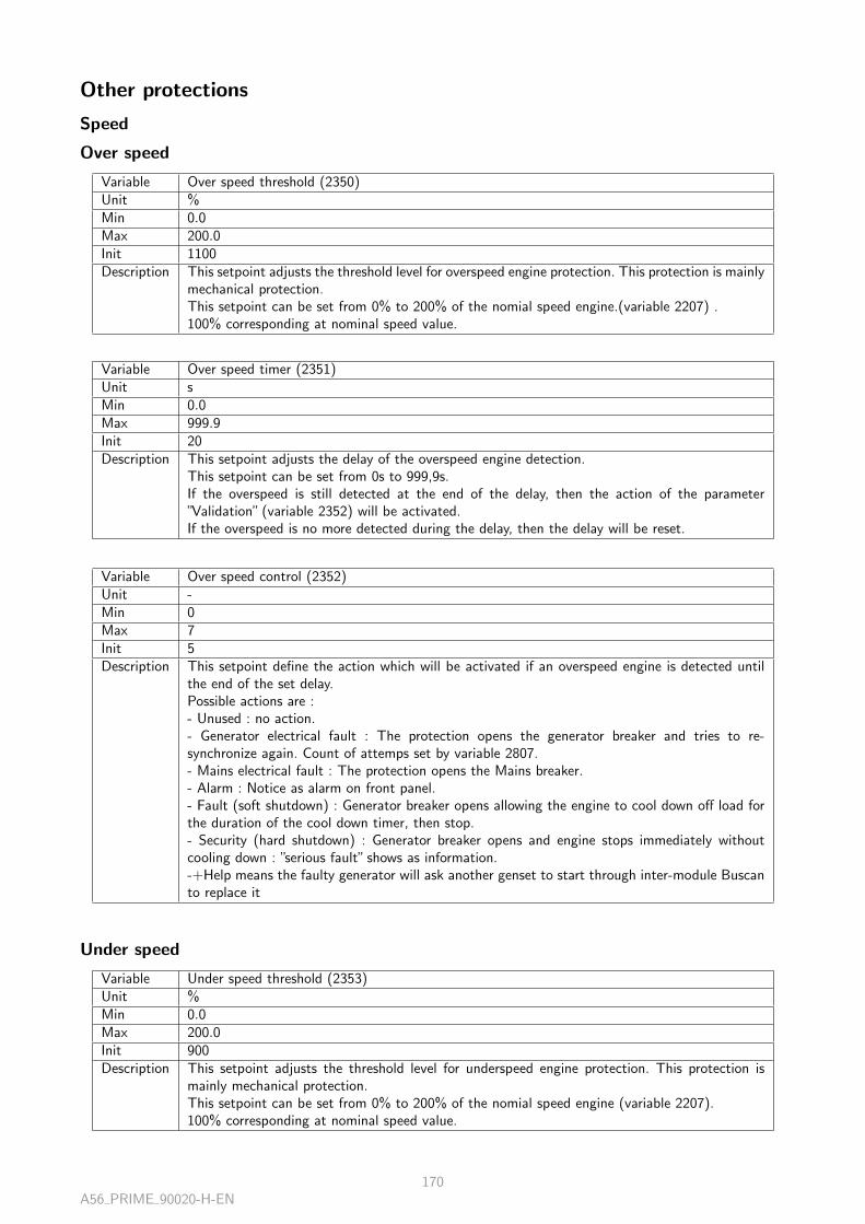
Other protections
Speed
Over speed
Variable Over speed threshold (2350)Unit %Min 0.0Max 200.0Init 1100Description This setpoint adjusts the threshold level for overspeed engine protection. This protection is mainly
mechanical protection.This setpoint can be set from 0% to 200% of the nomial speed engine.(variable 2207) .100% corresponding at nominal speed value.
Variable Over speed timer (2351)Unit sMin 0.0Max 999.9Init 20Description This setpoint adjusts the delay of the overspeed engine detection.
This setpoint can be set from 0s to 999,9s.If the overspeed is still detected at the end of the delay, then the action of the parameter”Validation” (variable 2352) will be activated.If the overspeed is no more detected during the delay, then the delay will be reset.
Variable Over speed control (2352)Unit -Min 0Max 7Init 5Description This setpoint define the action which will be activated if an overspeed engine is detected until
the end of the set delay.Possible actions are :- Unused : no action.- Generator electrical fault : The protection opens the generator breaker and tries to re-synchronize again. Count of attemps set by variable 2807.- Mains electrical fault : The protection opens the Mains breaker.- Alarm : Notice as alarm on front panel.- Fault (soft shutdown) : Generator breaker opens allowing the engine to cool down off load forthe duration of the cool down timer, then stop.- Security (hard shutdown) : Generator breaker opens and engine stops immediately withoutcooling down : ”serious fault” shows as information.-+Help means the faulty generator will ask another genset to start through inter-module Buscanto replace it
Under speed
Variable Under speed threshold (2353)Unit %Min 0.0Max 200.0Init 900Description This setpoint adjusts the threshold level for underspeed engine protection. This protection is
mainly mechanical protection.This setpoint can be set from 0% to 200% of the nomial speed engine (variable 2207).100% corresponding at nominal speed value.
A56 PRIME 90020-H-EN170

Variable Under speed timer (2354)Unit sMin 0.0Max 999.9Init 200Description This setpoint adjusts the delay of the underspeed engine detection.
This setpoint can be set from 0s to 999,9s.If the underpeed is still detected at the end of the delay, then the action of the parameter”Validation” (variable 2355) will be activated.If the underspeed is no more detected during the delay, then the delay will be reset.
Variable Under speed control (2355)Unit -Min 0Max 7Init 4Description This setpoint define the action which will be activated if an underspeed engine is detected until
the end of the set delay.Possible actions are :- Unused : no action.- Generator electrical fault : The protection opens the generator breaker and tries to re-synchronize again. Count of attemps set by variable 2807.- Mains electrical fault : The protection opens the Mains breaker.- Alarm : Notice as alarm on front panel.- Fault (soft shutdown) : Generator breaker opens allowing the engine to cool down off load forthe duration of the cool down timer, then stop.- Security (hard shutdown) : Generator breaker opens and engine stops immediately withoutcooling down : ”serious fault” shows as information.
Over speed 2
Variable Over speed threshold 2 (2368)Unit %Min 0.0Max 200.0Init 1150Description This setpoint adjusts the second threshold level for overspeed engine protection. This protection
is mainly mechanical protection.This setpoint can be set from 0% to 200% of the nomial speed engine.(variable 2207) .100% corresponding at nominal speed value.
Variable Over speed timer 2 (2369)Unit sMin 0.0Max 999.9Init 20Description This setpoint adjusts the delay of the overspeed engine detection of the second threshold level.
This setpoint can be set from 0s to 999,9s.If the overspeed is still detected at the end of the delay, then the action of the parameter”Validation” (variable 2370) will be activated.If the overspeed is no more detected during the delay, then the delay will be reset.
A56 PRIME 90020-H-EN171

Variable Over speed control 2 (2370)Unit -Min 0Max 7Init 0Description This setpoint define the action which will be activated if the second overspeed engine is detected
until the end of the set delay.Possible actions are :- Unused : no action.- Generator electrical fault : The protection opens the generator breaker and tries to re-synchronize again. Count of attemps set by variable 2807.- Mains electrical fault : The protection opens the Mains breaker.- Alarm : Notice as alarm on front panel.- Fault (soft shutdown) : Generator breaker opens allowing the engine to cool down off load forthe duration of the cool down timer, then stop.- Security (hard shutdown) : Generator breaker opens and engine stops immediately withoutcooling down : ”serious fault” shows as information.-+Help means the faulty generator will ask another genset to start through inter-module Buscanto replace it
Under speed 2
Variable Under speed threshold 2 (2371)Unit %Min 0.0Max 200.0Init 850Description This setpoint adjusts the second threshold level for underspeed engine protection. This protection
is mainly mechanical protection.This setpoint can be set from 0% to 200% of the nomial speed engine (variable 2207).100% corresponding at nominal speed value.
Variable Under speed timer 2 (2372)Unit sMin 0.0Max 999.9Init 200Description This setpoint adjusts the delay of the underspeed engine detection of the second threshold level.
This setpoint can be set from 0s to 999,9s.If the underspeed is still detected at the end of the delay, then the action of the parameter”Validation” (variable 2373) will be activated.If the underspeed is no more detected during the delay, then the delay will be reset.
A56 PRIME 90020-H-EN172

Variable Under speed control 2 (2373)Unit -Min 0Max 7Init 0Description This setpoint define the action which will be activated if the second underspeed engine is detec-
ted until the end of the set delay.Possible actions are :- Unused : no action.- Generator electrical fault : The protection opens the generator breaker and tries to re-synchronize again. Count of attemps set by variable 2807.- Mains electrical fault : The protection opens the Mains breaker.- Alarm : Notice as alarm on front panel.- Fault (soft shutdown) : Generator breaker opens allowing the engine to cool down off load forthe duration of the cool down timer, then stop.- Security (hard shutdown) : Generator breaker opens and engine stops immediately withoutcooling down : ”serious fault” shows as information.-+Help means the faulty generator will ask another genset to start through inter-module Buscanto replace it
Oil pressure/Water temperature
Maximum water temperature
Variable Water temperature threshold (2365)Unit °CMin −3276.7Max 3276.7Init 1100Description This setpoint adjusts the threshold level for maximal water temperature protection of the engine.
This protection is mainly mechanical protection.This setpoint can be set from -3200°C to +3200°C.
Variable Water temperature timer (2366)Unit sMin 0.0Max 999.9Init 300Description This setpoint adjusts the delay of the maximal water temperature detection.
This setpoint can be set from 0s to 999,9s.If the maximal temperature is still detected at the end of the delay, then the action of theparameter ”Validation” (variable 2367) will be activated.If the maximal temperature is no more detected during the delay, then the delay will be reset.
A56 PRIME 90020-H-EN173

Variable Water temperature control (2367)Unit -Min 0Max 7Init 0Description This setpoint define the action which will be activated if the threshold of maximal water tempe-
rature is detected until the end of the set delay.Possible actions are :- Unused : no action.- Generator electrical fault : The protection opens the generator breaker and tries to re-synchronize again. Count of attemps set by variable 2807.- Mains electrical fault : The protection opens the Mains breaker.- Alarm : Notice as alarm on front panel.- Fault (soft shutdown) : Generator breaker opens allowing the engine to cool down off load forthe duration of the cool down timer, then stop.- Security (hard shutdown) : Generator breaker opens and engine stops immediately withoutcooling down : ”serious fault” shows as information.-+Help means the faulty generator will ask another genset to start through inter-module Buscanto replace it
Minimum oil pressure
Variable Oil pressure threshold (2362)Unit mBarMin 0Max 6553.5Init 30 000Description This setpoint adjusts the threshold limit of the oil pressure of the engine.
This protection is mainly mechanical protection.This setpoint can be set from 0mBar to 6553,5mBar.
Variable Oil pressure timer (2363)Unit sMin 0.0Max 999.9Init 100Description This setpoint adjusts the delay of the oil pression limite detection.
This setpoint can be set from 0s to 999,9s.If the oil pressure limit is still detected at the end of the delay, then the action of the parameter”Validation” (variable 2364) will be activated.If the oil pressure limit is no more detected during the delay, then the delay will be reset.
A56 PRIME 90020-H-EN174

Variable Oil pressure control (2364)Unit -Min 0Max 7Init 0Description This setpoint define the action which will be activated if the oil pressure limit is detected until
the end of the set delay.Possible actions are :- Unused : no action.- Generator electrical fault : The protection opens the generator breaker and tries to re-synchronize again. Count of attemps set by variable 2807.- Mains electrical fault : The protection opens the Mains breaker.- Alarm : Notice as alarm on front panel.- Fault (soft shutdown) : Generator breaker opens allowing the engine to cool down off load forthe duration of the cool down timer, then stop.- Security (hard shutdown) : Generator breaker opens and engine stops immediately withoutcooling down : ”serious fault” shows as information-+Help means the faulty generator will ask another genset to start through inter-module Buscanto replace it
Maximum water temperature 2
Variable Water temperature threshold 2 (2383)Unit °CMin −3276.7Max 3276.7Init 1200Description This setpoint adjusts the second threshold level for maximal water temperature protection of the
engine.This protection is mainly mechanical protection.This setpoint can be set from -3200°C to +3200°C.
Variable Water temperature timer 2 (2384)Unit sMin 0.0Max 999.9Init 100Description This setpoint adjusts the delay of the maximal water temperature detection of the second thre-
shold level.This setpoint can be set from 0s to 999,9s.If the maximal temperature is still detected at the end of the delay, then the action of the para-meter ”Validation” (variable 2385) will be activated.If the maxmal temperature is no more detected during the delay, then the delay will be reset.
A56 PRIME 90020-H-EN175

Variable Water temperature control 2 (2385)Unit -Min 0Max 7Init 0Description This setpoint define the action which will be activated if the second threshold of maximal water
temperature is detected until the end of the set delay.Possible actions are :- Unused : no action.- Generator electrical fault : The protection opens the generator breaker and tries to re-synchronize again. Count of attemps set by variable 2807.- Mains electrical fault : The protection opens the Mains breaker.- Alarm : Notice as alarm on front panel.- Fault (soft shutdown) : Generator breaker opens allowing the engine to cool down off load forthe duration of the cool down timer, then stop.- Security (hard shutdown) : Generator breaker opens and engine stops immediately withoutcooling down : ”serious fault” shows as information.-+Help means the faulty generator will ask another genset to start through inter-module Buscanto replace it
Minimum oil pressure 2
Variable Oil pressure threshold 2 (2380)Unit mBarMin 0Max 6553.5Init 20 000Description This setpoint adjusts the second threshold limit of the oil pressure of the engine.
This protection is mainly mechanical protection.This setpoint can be set from 0mBar to 6553,5mBar.
Variable Oil pressure timer 2 (2381)Unit sMin 0.0Max 999.9Init 50Description This setpoint adjusts the delay of the oil pression limite detection of the second threshold level.
This setpoint can be set from 0s to 999,9s.If the oil pressure limit is still detected at the end of the delay, then the action of the parameter”Validation” (variable 2382) will be activated.If the oil pressure limit is no more detected during the delay, then the delay will be reset.
A56 PRIME 90020-H-EN176

Variable Oil pressure control 2 (2382)Unit -Min 0Max 7Init 0Description This setpoint define the action which will be activated if the second oil pressure limit is detected
until the end of the set delay.Possible actions are :- Unused : no action.- Generator electrical fault : The protection opens the generator breaker and tries to re-synchronize again. Count of attemps set by variable 2807.- Mains electrical fault : The protection opens the Mains breaker.- Alarm : Notice as alarm on front panel.- Fault (soft shutdown) : Generator breaker opens allowing the engine to cool down off load forthe duration of the cool down timer, then stop.- Security (hard shutdown) : Generator breaker opens and engine stops immediately withoutcooling down : ”serious fault” shows as information.-+Help means the faulty generator will ask another genset to start through inter-module Buscanto replace it
Analog inputs
Analog input 1
Variable AN1 min/max (Customisable) (4206)Unit -Min 0Max 3Init -Description This value is to customize the label of analog input 1 protection.
The maximum number of caracters is of 14.This protection use the analog input 1 set in the ”Analog inputs” chapiter (variable 150).
Variable Analog input 1 threshold (2600)Unit -Min −32 767Max 32 767Init 0Description This setpoint adjusts the threshold level for analog input 1 protection.
The setting of this setpoint is according to the unit selected for the analog input 1 (variable150).
Variable Analog input 1 timer (2601)Unit sMin 0.0Max 999.9Init 0Description This setpoint adjusts the delay of the threshold level for analog input 1 detection.
This setpoint can be set from 0s to 999,9s.If the threshold’s analog input 1 is still detected at the end of the delay, then the action of theparameter ”Validation” (variable 2602) will be activated.If the threshold’s analog input 1 is no more detected during the delay, then the delay will bereset.
A56 PRIME 90020-H-EN177

Variable Analog input 1 control (2602)Unit -Min 0Max 7Init 0Description This setpoint define the action which will be activated if the threshold level for analog input 1
is detected until the end of the set delay.Possible actions are :- Unused : no action.- Generator electrical fault : The protection opens the generator breaker and tries to re-synchronize again. Count of attemps set by variable 2807.- Mains electrical fault : The protection opens the Mains breaker.- Alarm : Notice as alarm on front panel.- Fault (soft shutdown) : Generator breaker opens allowing the engine to cool down off load forthe duration of the cool down timer, then stop.- Security (hard shutdown) : Generator breaker opens and engine stops immediately withoutcooling down : ”serious fault” shows as information.-+Help means the faulty generator will ask another genset to start through inter-module Buscanto replace it
Variable Analog input 1 threshold 2 (2603)Unit -Min −32 767Max 32 767Init 0Description This setpoint adjusts the second threshold level for analog input 1 protection.
The setting of this setpoint is according to the unit selected for the analog input 1 (variable150).
Variable Analog input 1 timer 2 (2604)Unit sMin 0.0Max 999.9Init 0Description This setpoint adjusts the delay of the second threshold level for analog input 1 detection.
This setpoint can be set from 0s to 999,9s.If the second threshold’s analog input 1 is still detected at the end of the delay, then the actionof the parameter ”Validation” (variable 2605) will be activated.If the second threshold’s analog input 1 is no more detected during the delay, then the delay willbe reset.
Variable Analog input 1 control 2 (2605)Unit -Min 0Max 7Init 0Description This setpoint define the action which will be activated if the second threshold level for analog
input 1 is detected until the end of the set delay.Possible actions are :- Unused : no action.- Generator electrical fault : The protection opens the generator breaker and tries to re-synchronize again. Count of attemps set by variable 2807.- Mains electrical fault : The protection opens the Mains breaker.- Alarm : Notice as alarm on front panel.- Fault (soft shutdown) : Generator breaker opens allowing the engine to cool down off load forthe duration of the cool down timer, then stop.- Security (hard shutdown) : Generator breaker opens and engine stops immediately withoutcooling down : ”serious fault” shows as information.-+Help means the faulty generator will ask another genset to start through inter-module Buscanto replace it
A56 PRIME 90020-H-EN178

Variable Direction analog input 1 protection (2606)Unit -Min 0Max 1Init 0Description This setpoint define if the both threshold level for analog input 1 are minimum or maximum
limit.If the setpoint is on ”Minimum” then the action of vaiables 2602 and 2605 will activate fromthresholds level set and below.If the setpoint is on ”Maximum” then the action of vaiables 2602 and 2605 will activate fromthresholds level set and above.
Analog input 2
Variable AN2 min/max (Customisable) (4207)Unit -Min 0Max 3Init -Description This value is to customize the label of analog input 2 protection.
The maximum number of caracters is of 14.This protection use the analog input 2 set in the ”Analog inputs” chapiter (variable 151).
Variable Analog input 2 threshold (2608)Unit -Min −32 767Max 32 767Init 0Description This setpoint adjusts the threshold level for analog input 2 protection.
The setting of this setpoint is according to the unit selected for the analog input 2 (variable151).
Variable Analog input 2 timer (2609)Unit sMin 0.0Max 999.9Init 0Description This setpoint adjusts the delay of the threshold level for analog input 2 detection.
This setpoint can be set from 0s to 999,9s.If the threshold’s analog input 2 is still detected at the end of the delay, then the action of theparameter ”Validation” (variable 2610) will be activated.If the threshold’s analog input 2 is no more detected during the delay, then the delay will bereset.
A56 PRIME 90020-H-EN179

Variable Analog input 2 control (2610)Unit -Min 0Max 7Init 0Description This setpoint define the action which will be activated if the threshold level for analog input 2
is detected until the end of the set delay.Possible actions are :- Unused : no action.- Generator electrical fault : The protection opens the generator breaker and tries to re-synchronize again. Count of attemps set by variable 2807.- Mains electrical fault : The protection opens the Mains breaker.- Alarm : Notice as alarm on front panel.- Fault (soft shutdown) : Generator breaker opens allowing the engine to cool down off load forthe duration of the cool down timer, then stop.- Security (hard shutdown) : Generator breaker opens and engine stops immediately withoutcooling down : ”serious fault” shows as information.-+Help means the faulty generator will ask another genset to start through inter-module Buscanto replace it
Variable Analog input 2 threshold 2 (2611)Unit -Min −32 767Max 32 767Init 0Description This setpoint adjusts the second threshold level for analog input 2 protection.
The setting of this setpoint is according to the unit selected for the analog input 2 (variable151).
Variable Analog input 2 timer 2 (2612)Unit sMin 0.0Max 999.9Init 0Description This setpoint adjusts the delay of the second threshold level for analog input 2 detection.
This setpoint can be set from 0s to 999,9s.If the second threshold’s analog input 2 is still detected at the end of the delay, then the actionof the parameter ”Validation” (variable 2613) will be activated.If the second threshold’s analog input 2 is no more detected during the delay, then the delay willbe reset.
Variable Analog input 2 control 2 (2613)Unit -Min 0Max 7Init 0Description This setpoint define the action which will be activated if the second threshold level for analog
input 2 is detected until the end of the set delay.Possible actions are :- Unused : no action.- Generator electrical fault : The protection opens the generator breaker and tries to re-synchronize again. Count of attemps set by variable 2807.- Mains electrical fault : The protection opens the Mains breaker.- Alarm : Notice as alarm on front panel.- Fault (soft shutdown) : Generator breaker opens allowing the engine to cool down off load forthe duration of the cool down timer, then stop.- Security (hard shutdown) : Generator breaker opens and engine stops immediately withoutcooling down : ”serious fault” shows as information.-+Help means the faulty generator will ask another genset to start through inter-module Buscanto replace it
A56 PRIME 90020-H-EN180

Variable Direction analog input 2 protection (2614)Unit -Min 0Max 1Init 0Description This setpoint define if the both threshold level for analog input 2 are minimum or maximum
limit.If the setpoint is on ”Minimum” then the action of vaiables 2610 and 2613 will activate fromthresholds level set and below.If the setpoint is on ”Maximum” then the action of vaiables 2610 and 2613 will activate fromthresholds level set and above.
Analog input 3
Variable AN3 min/max (Customisable) (4208)Unit -Min 0Max 3Init -Description This value is to customize the label of analog input 3 protection.
The maximum number of caracters is of 14.This protection use the analog input 3 set in the ”Analog inputs” chapiter (variable 152).
Variable Analog input 3 threshold (2616)Unit -Min −32 767Max 32 767Init 0Description This setpoint adjusts the threshold level for analog input 3 protection.
The setting of this setpoint is according to the unit selected for the analog input 3 (variable152).
Variable Analog input 3 timer (2617)Unit sMin 0.0Max 999.9Init 0Description This setpoint adjusts the delay of the threshold level for analog input 3 detection.
This setpoint can be set from 0s to 999,9s.If the threshold’s analog input 3 is still detected at the end of the delay, then the action of theparameter ”Validation” (variable 2618) will be activated.If the threshold’s analog input 3 is no more detected during the delay, then the delay will bereset.
A56 PRIME 90020-H-EN181

Variable Analog input 3 control (2618)Unit -Min 0Max 7Init 0Description This setpoint define the action which will be activated if the threshold level for analog input 3
is detected until the end of the set delay.Possible actions are :- Unused : no action.- Generator electrical fault : The protection opens the generator breaker and tries to re-synchronize again. Count of attemps set by variable 2807.- Mains electrical fault : The protection opens the Mains breaker.- Alarm : Notice as alarm on front panel.- Fault (soft shutdown) : Generator breaker opens allowing the engine to cool down off load forthe duration of the cool down timer, then stop.- Security (hard shutdown) : Generator breaker opens and engine stops immediately withoutcooling down : ”serious fault” shows as information.-+Help means the faulty generator will ask another genset to start through inter-module Buscanto replace it
Variable Analog input 3 threshold 2 (2619)Unit -Min −32 767Max 32 767Init 0Description This setpoint adjusts the second threshold level for analog input 3 protection.
The setting of this setpoint is according to the unit selected for the analog input 3 (variable152).
Variable Analog input 3 timer 2 (2620)Unit sMin 0.0Max 999.9Init 0Description This setpoint adjusts the delay of the second threshold level for analog input 3 detection.
This setpoint can be set from 0s to 999,9s.If the second threshold’s analog input 3 is still detected at the end of the delay, then the actionof the parameter ”Validation” (variable 2621) will be activated.If the second threshold’s analog input 3 is no more detected during the delay, then the delay willbe reset.
Variable Analog input 3 control 2 (2621)Unit -Min 0Max 7Init 0Description This setpoint define the action which will be activated if the second threshold level for analog
input 3 is detected until the end of the set delay.Possible actions are :- Unused : no action.- Generator electrical fault : The protection opens the generator breaker and tries to re-synchronize again. Count of attemps set by variable 2807.- Mains electrical fault : The protection opens the Mains breaker.- Alarm : Notice as alarm on front panel.- Fault (soft shutdown) : Generator breaker opens allowing the engine to cool down off load forthe duration of the cool down timer, then stop.- Security (hard shutdown) : Generator breaker opens and engine stops immediately withoutcooling down : ”serious fault” shows as information.-+Help means the faulty generator will ask another genset to start through inter-module Buscanto replace it
A56 PRIME 90020-H-EN182

Variable Direction analog input 1 protection (2622)Unit -Min 0Max 1Init 0Description This setpoint define if the both threshold level for analog input 3 are minimum or maximum
limit.If the setpoint is on ”Minimum” then the action of vaiables 2618 and 2621 will activate fromthresholds level set and below.If the setpoint is on ”Maximum” then the action of vaiables 2618 and 2621 will activate fromthresholds level set and above.
Battery
Maximum battery voltage
Variable Max. voltage battery threshold (2359)Unit VMin 0.0Max 35.0Init 300Description This setpoint adjusts the warning level for battery overvoltage protection.
This protection is mainly electrical protection.This setpoint can be set from 0V to 35V.
Variable Max. voltage battery timer (2360)Unit sMin 0.0Max 999.9Init 100Description This setpoint adjusts the delay of the battery overvoltage detection.
This setpoint can be set from 0s to 999,9s.If the overvoltage is still detected at the end of the delay, then the action of the parameter”Validation” (variable 2361) will be activated.If the overvoltage is no more detected during the delay, then the delay will be reset.
Variable Max. voltage battery control (2361)Unit -Min 0Max 7Init 0Description This setpoint define the action which will be activated if a battery overvoltage is detected until
the end of the set delay.Possible actions are :- Unused : no action.- Generator electrical fault : The protection opens the generator breaker and tries to re-synchronize again. Count of attemps set by variable 2807.- Mains electrical fault : The protection opens the Mains breaker.- Alarm : Notice as alarm on front panel.- Fault (soft shutdown) : Generator breaker opens allowing the engine to cool down off load forthe duration of the cool down timer, then stop.- Security (hard shutdown) : Generator breaker opens and engine stops immediately withoutcooling down : ”serious fault” shows as information.
A56 PRIME 90020-H-EN183

Minimum battery voltage
Variable Min. voltage battery threshold (2356)Unit VMin 0.0Max 35.0Init 180Description This setpoint adjusts the warning level for battery undervoltage protection.
This protection is mainly electrical protection.This setpoint can be set from 0V to 35V.
Variable Min. voltage battery timer (2357)Unit sMin 0.0Max 999.9Init 600Description This setpoint adjusts the delay of the battery undervoltage detection.
This setpoint can be set from 0s to 999,9s.If the undervoltage is still detected at the end of the delay, then the action of the parameter”Validation” (variable 2358) will be activated.If the undervoltage is no more detected during the delay, then the delay will be reset.
Variable Min. voltage battery control (2358)Unit -Min 0Max 7Init 0Description This setpoint define the action which will be activated if a battery undervoltage is detected until
the end of the set delay.Possible actions are :- Unused : no action.- Generator electrical fault : The protection opens the generator breaker and tries to re-synchronize again. Count of attemps set by variable 2807.- Mains electrical fault : The protection opens the Mains breaker.- Alarm : Notice as alarm on front panel.- Fault (soft shutdown) : Generator breaker opens allowing the engine to cool down off load forthe duration of the cool down timer, then stop.- Security (hard shutdown) : Generator breaker opens and engine stops immediately withoutcooling down : ”serious fault” shows as information.
Maximum battery voltage 2
Variable Max. voltage battery threshold 2 (2377)Unit VMin 0.0Max 35.0Init 320Description This setpoint adjusts the warning level for battery 2 overvoltage protection.
This protection is mainly electrical protection.This setpoint can be set from 0V to 35V.
A56 PRIME 90020-H-EN184

Variable Max. voltage battery timer 2 (2378)Unit sMin 0.0Max 999.9Init 50Description This setpoint adjusts the delay of the battery 2 overvoltage detection.
This setpoint can be set from 0s to 999,9s.If the overvoltage is still detected at the end of the delay, then the action of the parameter”Validation” (variable 2361) will be activated.If the overvoltage is no more detected during the delay, then the delay will be reset.
Variable Max. voltage battery control 2 (2379)Unit -Min 0Max 7Init 0Description This setpoint define the action which will be activated if a battery 2 overvoltage is detected until
the end of the set delay.Possible actions are :- Unused : no action.- Generator electrical fault : The protection opens the generator breaker and tries to re-synchronize again. Count of attemps set by variable 2807.- Mains electrical fault : The protection opens the Mains breaker.- Alarm : Notice as alarm on front panel.- Fault (soft shutdown) : Generator breaker opens allowing the engine to cool down off load forthe duration of the cool down timer, then stop.- Security (hard shutdown) : Generator breaker opens and engine stops immediately withoutcooling down : ”serious fault” shows as information.-+Help means the faulty generator will ask another genset to start through inter-module Buscanto replace it
Minimum battery voltage 2
Variable Min. voltage battery threshold 2 (2374)Unit VMin 0.0Max 35.0Init 150Description This setpoint adjusts the warning level for battery 2 undervoltage protection.
This protection is mainly electrical protection.This setpoint can be set from 0V to 35V.
Variable Min. voltage battery timer 2 (2375)Unit sMin 0.0Max 999.9Init 100Description This setpoint adjusts the delay of the battery 2 undervoltage detection.
This setpoint can be set from 0s to 999,9s.If the undervoltage is still detected at the end of the delay, then the action of the parameter”Validation” (variable 2358) will be activated.If the undervoltage is no more detected during the delay, then the delay will be reset.
A56 PRIME 90020-H-EN185

Variable Min. voltage battery control 2 (2376)Unit -Min 0Max 7Init 0Description This setpoint define the action which will be activated if a battery 2 undervoltage is detected
until the end of the set delay.Possible actions are :- Unused : no action.- Generator electrical fault : The protection opens the generator breaker and tries to re-synchronize again. Count of attemps set by variable 2807.- Mains electrical fault : The protection opens the Mains breaker.- Alarm : Notice as alarm on front panel.- Fault (soft shutdown) : Generator breaker opens allowing the engine to cool down off load forthe duration of the cool down timer, then stop.- Security (hard shutdown) : Generator breaker opens and engine stops immediately withoutcooling down : ”serious fault” shows as information.-+Help means the faulty generator will ask another genset to start through inter-module Buscanto replace it
Boost battery
Variable Control boost battery (2388)Unit -Min 0Max 1Init 0Description This setpoint activate the boost battery function.
This function activate the boost battery output with a low threshold (variable 2386) of thebattery voltage and deactivate the output with high threshold (variable 2387).
Variable Low threshold boost battery (2386)Unit VMin 0.0Max 35.0Init 200Description This setpoint adjusts the low threshold level to activate the boost battery output.
This setpoint can be set only if the variable 2388 is activated.This setpoint can be set from 0V to 35V.
Variable High threshold boost battery (2387)Unit VMin 0.0Max 35.0Init 280Description This setpoint adjusts the high threshold level to deactivate the boost battery output.
This setpoint can be set only if the variable 2388 is activated.This setpoint can be set from 0V to 35V.This threshold have to be higher than the low threshold (variable 2386).
Outputs
Max/Min speed output
A56 PRIME 90020-H-EN186

Variable Timer Min Max Speed output (2389)Unit sMin 0.0Max 999.9Init 100Description Timer acceptance before alarm for speed output signal to speed governor to stay at Minimum
or Maximum signal correction
Variable Control Min Max Speed output (2390)Unit -Min 0Max 7Init 0Description Control selection when speed output signal protection become active. The selections are the
following :- Unused : no action.- Generator electrical fault : The protection opens the generator breaker and tries to re-synchronize again. Count of attemps set by variable 2807.- Mains electrical fault : The protection opens the Mains breaker.- Alarm : Notice as alarm on front panel.- Fault (soft shutdown) : Generator breaker opens allowing the engine to cool down off load forthe duration of the cool down timer, then stop.- Security (hard shutdown) : Generator breaker opens and engine stops immediately withoutcooling down : ”serious fault” shows as information.- +Help means the faulty generator will ask another genset to start through inter-module Buscanto replace it.
Max/Min AVR output
Variable Timer Min Max AVR output (2391)Unit sMin 0.0Max 999.9Init 100Description Timer acceptance before alarm for voltage output signal to AVR/DVR regulator to stay at
Minimum or Maximum signal correction
Variable Control Min Max AVR output (2392)Unit -Min 0Max 7Init 0Description Control selection when AVR output signal protection become active.The selections are the follo-
wing :- Unused : no action.- Generator electrical fault : The protection opens the generator breaker and tries to re-synchronize again. Count of attemps set by variable 2807.- Mains electrical fault : The protection opens the Mains breaker.- Alarm : Notice as alarm on front panel.- Fault (soft shutdown) : Generator breaker opens allowing the engine to cool down off load forthe duration of the cool down timer, then stop.- Security (hard shutdown) : Generator breaker opens and engine stops immediately withoutcooling down : ”serious fault” shows as information.- +Help means the faulty generator will ask another genset to start through inter-module Buscanto replace it.
A56 PRIME 90020-H-EN187
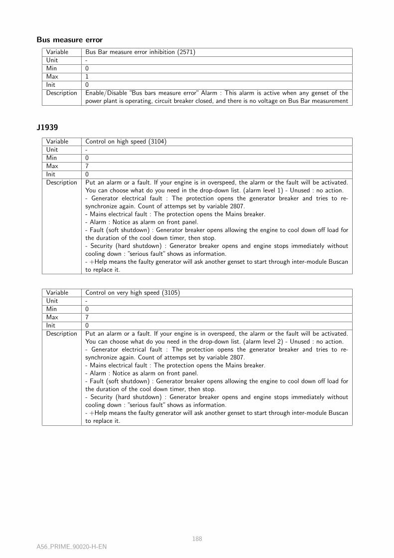
Bus measure error
Variable Bus Bar measure error inhibition (2571)Unit -Min 0Max 1Init 0Description Enable/Disable ”Bus bars measure error” Alarm : This alarm is active when any genset of the
power plant is operating, circuit breaker closed, and there is no voltage on Bus Bar measurement
J1939
Variable Control on high speed (3104)Unit -Min 0Max 7Init 0Description Put an alarm or a fault. If your engine is in overspeed, the alarm or the fault will be activated.
You can choose what do you need in the drop-down list. (alarm level 1) - Unused : no action.- Generator electrical fault : The protection opens the generator breaker and tries to re-synchronize again. Count of attemps set by variable 2807.- Mains electrical fault : The protection opens the Mains breaker.- Alarm : Notice as alarm on front panel.- Fault (soft shutdown) : Generator breaker opens allowing the engine to cool down off load forthe duration of the cool down timer, then stop.- Security (hard shutdown) : Generator breaker opens and engine stops immediately withoutcooling down : ”serious fault” shows as information.- +Help means the faulty generator will ask another genset to start through inter-module Buscanto replace it.
Variable Control on very high speed (3105)Unit -Min 0Max 7Init 0Description Put an alarm or a fault. If your engine is in overspeed, the alarm or the fault will be activated.
You can choose what do you need in the drop-down list. (alarm level 2) - Unused : no action.- Generator electrical fault : The protection opens the generator breaker and tries to re-synchronize again. Count of attemps set by variable 2807.- Mains electrical fault : The protection opens the Mains breaker.- Alarm : Notice as alarm on front panel.- Fault (soft shutdown) : Generator breaker opens allowing the engine to cool down off load forthe duration of the cool down timer, then stop.- Security (hard shutdown) : Generator breaker opens and engine stops immediately withoutcooling down : ”serious fault” shows as information.- +Help means the faulty generator will ask another genset to start through inter-module Buscanto replace it.
A56 PRIME 90020-H-EN188

Variable Control on high coolant temperature (3106)Unit -Min 0Max 7Init 0Description Put an alarm or a fault. If your engine is in overheat, the alarm or the fault will be activated.
You can choose what do you need in the drop-down list. (alarm level 1) - Unused : no action.- Generator electrical fault : The protection opens the generator breaker and tries to re-synchronize again. Count of attemps set by variable 2807.- Mains electrical fault : The protection opens the Mains breaker.- Alarm : Notice as alarm on front panel.- Fault (soft shutdown) : Generator breaker opens allowing the engine to cool down off load forthe duration of the cool down timer, then stop.- Security (hard shutdown) : Generator breaker opens and engine stops immediately withoutcooling down : ”serious fault” shows as information.- +Help means the faulty generator will ask another genset to start through inter-module Buscanto replace it.
Variable Control on very high coolant temperature (3107)Unit -Min 0Max 7Init 0Description Put an alarm or a fault. If your engine is in overheat, the alarm or the fault will be activated.
You can choose what do you need in the drop-down list. (alarm level 2) - Unused : no action.- Generator electrical fault : The protection opens the generator breaker and tries to re-synchronize again. Count of attemps set by variable 2807.- Mains electrical fault : The protection opens the Mains breaker.- Alarm : Notice as alarm on front panel.- Fault (soft shutdown) : Generator breaker opens allowing the engine to cool down off load forthe duration of the cool down timer, then stop.- Security (hard shutdown) : Generator breaker opens and engine stops immediately withoutcooling down : ”serious fault” shows as information.- +Help means the faulty generator will ask another genset to start through inter-module Buscanto replace it.
Variable Control on low oil pressure (3108)Unit -Min 0Max 7Init 0Description Put an alarm or a fault. If your engine have a low oil pressure, the alarm or the fault will be
activated. You can choose what do you need in the drop-down list. (alarm level 1) - Unused : noaction.- Generator electrical fault : The protection opens the generator breaker and tries to re-synchronize again. Count of attemps set by variable 2807.- Mains electrical fault : The protection opens the Mains breaker.- Alarm : Notice as alarm on front panel.- Fault (soft shutdown) : Generator breaker opens allowing the engine to cool down off load forthe duration of the cool down timer, then stop.- Security (hard shutdown) : Generator breaker opens and engine stops immediately withoutcooling down : ”serious fault” shows as information.- +Help means the faulty generator will ask another genset to start through inter-module Buscanto replace it.
A56 PRIME 90020-H-EN189
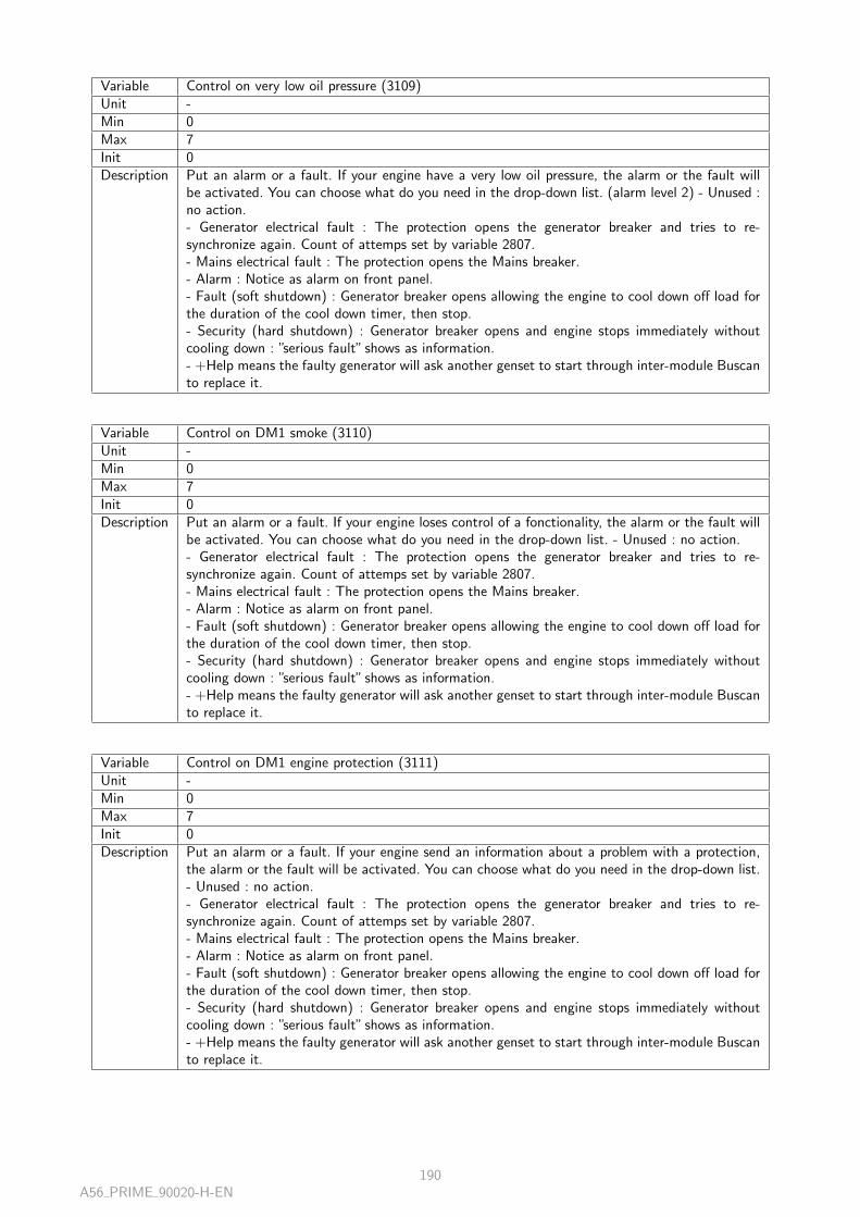
Variable Control on very low oil pressure (3109)Unit -Min 0Max 7Init 0Description Put an alarm or a fault. If your engine have a very low oil pressure, the alarm or the fault will
be activated. You can choose what do you need in the drop-down list. (alarm level 2) - Unused :no action.- Generator electrical fault : The protection opens the generator breaker and tries to re-synchronize again. Count of attemps set by variable 2807.- Mains electrical fault : The protection opens the Mains breaker.- Alarm : Notice as alarm on front panel.- Fault (soft shutdown) : Generator breaker opens allowing the engine to cool down off load forthe duration of the cool down timer, then stop.- Security (hard shutdown) : Generator breaker opens and engine stops immediately withoutcooling down : ”serious fault” shows as information.- +Help means the faulty generator will ask another genset to start through inter-module Buscanto replace it.
Variable Control on DM1 smoke (3110)Unit -Min 0Max 7Init 0Description Put an alarm or a fault. If your engine loses control of a fonctionality, the alarm or the fault will
be activated. You can choose what do you need in the drop-down list. - Unused : no action.- Generator electrical fault : The protection opens the generator breaker and tries to re-synchronize again. Count of attemps set by variable 2807.- Mains electrical fault : The protection opens the Mains breaker.- Alarm : Notice as alarm on front panel.- Fault (soft shutdown) : Generator breaker opens allowing the engine to cool down off load forthe duration of the cool down timer, then stop.- Security (hard shutdown) : Generator breaker opens and engine stops immediately withoutcooling down : ”serious fault” shows as information.- +Help means the faulty generator will ask another genset to start through inter-module Buscanto replace it.
Variable Control on DM1 engine protection (3111)Unit -Min 0Max 7Init 0Description Put an alarm or a fault. If your engine send an information about a problem with a protection,
the alarm or the fault will be activated. You can choose what do you need in the drop-down list.- Unused : no action.- Generator electrical fault : The protection opens the generator breaker and tries to re-synchronize again. Count of attemps set by variable 2807.- Mains electrical fault : The protection opens the Mains breaker.- Alarm : Notice as alarm on front panel.- Fault (soft shutdown) : Generator breaker opens allowing the engine to cool down off load forthe duration of the cool down timer, then stop.- Security (hard shutdown) : Generator breaker opens and engine stops immediately withoutcooling down : ”serious fault” shows as information.- +Help means the faulty generator will ask another genset to start through inter-module Buscanto replace it.
A56 PRIME 90020-H-EN190

Variable Control on DM1 warning (3112)Unit -Min 0Max 7Init 0Description Put an alarm or a fault. If your engine have an alarm, the alarm or the fault Module will be
activated. You can choose what do you need in the drop-down list. - Unused : no action.- Generator electrical fault : The protection opens the generator breaker and tries to re-synchronize again. Count of attemps set by variable 2807.- Mains electrical fault : The protection opens the Mains breaker.- Alarm : Notice as alarm on front panel.- Fault (soft shutdown) : Generator breaker opens allowing the engine to cool down off load forthe duration of the cool down timer, then stop.- Security (hard shutdown) : Generator breaker opens and engine stops immediately withoutcooling down : ”serious fault” shows as information.- +Help means the faulty generator will ask another genset to start through inter-module Buscanto replace it.
Variable Control on DM1 alarm (3113)Unit -Min 0Max 7Init 0Description Put an alarm or a fault. If your engine have a fault, the alarm or the fault Module will be acti-
vated. You can choose what do you need in the drop-down list. - Unused : no action.- Generator electrical fault : The protection opens the generator breaker and tries to re-synchronize again. Count of attemps set by variable 2807.- Mains electrical fault : The protection opens the Mains breaker.- Alarm : Notice as alarm on front panel.- Fault (soft shutdown) : Generator breaker opens allowing the engine to cool down off load forthe duration of the cool down timer, then stop.- Security (hard shutdown) : Generator breaker opens and engine stops immediately withoutcooling down : ”serious fault” shows as information.- +Help means the faulty generator will ask another genset to start through inter-module Buscanto replace it.
CANopen
CANopen
CANopen
Variable CAN2 baud rate (3051)Unit -Min 0Max 65 535Init 125Description CAN bus 2 baud speed (J1939/CANopen)
Variable Error timer (3152)Unit sMin 0.0Max 6553.5Init 100Description CANopen error timer
A56 PRIME 90020-H-EN191

Coupler 1
Variable Coupler ID # 1 (3153)Unit -Min 0Max 255Init 0Description Coupler identifier, In client Config mode, we can add several couplers and for each coupler a
unique identifier is dedicated by the client
Variable CANopen IN 1 (3154)Unit -Min 0Max 32Init 0Description Each coupler is associated with an input number
Variable CANopen OUT 1 (3155)Unit -Min 0Max 32Init 0Description Each coupler is associated with output number
Coupler 2
Variable Coupler ID # 2 (3156)Unit -Min 0Max 255Init 0Description Coupler identifier, In client Config mode, we can add several couplers and for each coupler a
unique identifier is dedicated by the client
Variable CANopen IN 2 (3157)Unit -Min 0Max 32Init 0Description Each coupler is associated with an input number
Variable CANopen OUT 2 (3158)Unit -Min 0Max 32Init 0Description Each coupler is associated with output number
Coupler 3
Variable Coupler ID # 3 (3159)Unit -Min 0Max 255Init 0Description Coupler identifier, In client Config mode, we can add several couplers and for each coupler a
unique identifier is dedicated by the client
A56 PRIME 90020-H-EN192

Variable CANopen IN 3 (3160)Unit -Min 0Max 32Init 0Description Each coupler is associated with an input number
Variable CANopen OUT 3 (3161)Unit -Min 0Max 32Init 0Description Each coupler is associated with output number
Coupler 4
Variable Coupler ID # 4 (3162)Unit -Min 0Max 255Init 0Description Coupler identifier, In client Config mode, we can add several couplers and for each coupler a
unique identifier is dedicated by the client
Variable CANopen IN 4 (3163)Unit -Min 0Max 32Init 0Description Each coupler is associated with an input number
Variable CANopen OUT 4 (3164)Unit -Min 0Max 32Init 0Description Each coupler is associated with output number
CANopen outputs
Variable CANopen digital output n°1 (4751)Unit -Min 0Max 1Init -Description CANopen digital output 1
Variable CANopen digital output n°2 (4752)Unit -Min 0Max 1Init -Description CANopen digital output 2
A56 PRIME 90020-H-EN193

Variable CANopen digital output n°3 (4753)Unit -Min 0Max 1Init -Description CANopen digital output 3
Variable CANopen digital output n°4 (4754)Unit -Min 0Max 1Init -Description CANopen digital output 4
Variable CANopen digital output n°5 (4755)Unit -Min 0Max 1Init -Description CANopen digital output 5
Variable CANopen digital output n°6 (4756)Unit -Min 0Max 1Init -Description CANopen digital output 6
Variable CANopen digital output n°7 (4757)Unit -Min 0Max 1Init -Description CANopen digital output 7
Variable CANopen digital output n°8 (4758)Unit -Min 0Max 1Init -Description CANopen digital output 8
Variable CANopen digital output n°9 (4759)Unit -Min 0Max 1Init -Description CANopen digital output 9
Variable CANopen digital output n°10 (4760)Unit -Min 0Max 1Init -Description CANopen digital output 10
A56 PRIME 90020-H-EN194

Variable CANopen digital output n°11 (4761)Unit -Min 0Max 1Init -Description CANopen digital output 11
Variable CANopen digital output n°12 (4762)Unit -Min 0Max 1Init -Description CANopen digital output 12
Variable CANopen digital output n°13 (4763)Unit -Min 0Max 1Init -Description CANopen digital output 13
Variable CANopen digital output n°14 (4764)Unit -Min 0Max 1Init -Description CANopen digital output 14
Variable CANopen digital output n°15 (4765)Unit -Min 0Max 1Init -Description CANopen digital output 15
Variable CANopen digital output n°16 (4766)Unit -Min 0Max 1Init -Description CANopen digital output 16
Variable CANopen digital output n°17 (4767)Unit -Min 0Max 1Init -Description CANopen digital output 17
Variable CANopen digital output n°18 (4768)Unit -Min 0Max 1Init -Description CANopen digital output 18
A56 PRIME 90020-H-EN195

Variable CANopen digital output n°19 (4769)Unit -Min 0Max 1Init -Description CANopen digital output 19
Variable CANopen digital output n°20 (4770)Unit -Min 0Max 1Init -Description CANopen digital output 20
Variable CANopen digital output n°21 (4771)Unit -Min 0Max 1Init -Description CANopen digital output 21
Variable CANopen digital output n°22 (4772)Unit -Min 0Max 1Init -Description CANopen digital output 22
Variable CANopen digital output n°23 (4773)Unit -Min 0Max 1Init -Description CANopen digital output 23
Variable CANopen digital output n°24 (4774)Unit -Min 0Max 1Init -Description CANopen digital output 24
Variable CANopen digital output n°25 (4775)Unit -Min 0Max 1Init -Description CANopen digital output 25
Variable CANopen digital output n°26 (4776)Unit -Min 0Max 1Init -Description CANopen digital output 26
A56 PRIME 90020-H-EN196

Variable CANopen digital output n°27 (4777)Unit -Min 0Max 1Init -Description CANopen digital output 27
Variable CANopen digital output n°28 (4778)Unit -Min 0Max 1Init -Description CANopen digital output 28
Variable CANopen digital output n°29 (4779)Unit -Min 0Max 1Init -Description CANopen digital output 29
Variable CANopen digital output n°30 (4780)Unit -Min 0Max 1Init -Description CANopen digital output 30
Variable CANopen digital output n°31 (4781)Unit -Min 0Max 1Init -Description CANopen digital output 31
Variable CANopen digital output n°32 (4782)Unit -Min 0Max 1Init -Description CANopen digital output 32
Timers
Ramp timer
Variable Load ramp timer (2853)Unit sMin 0.0Max 1600.0Init 300Description This setpoint adjusts the load ramp timer, for load sharing or mains paralleling mode.
100 % of this timer corresponds to transfer 100% of generator nominal kW.For a ramp, to transfer, from 10% to 60% of nominal kW, the time will be 50% of the set timer.
A56 PRIME 90020-H-EN197

Variable Unload ramp timer (2856)Unit sMin 0.0Max 1600.0Init 300Description This setpoint adjusts the unload ramp timer, for load sharing or mains paralleling mode.
100 % of this timer corresponds to transfer 100% of generator nominal kW.For a ramp, to transfer, from 60% to 10% of nominal kW, the time will be 50% of the set timer.
Breaker
Variable Fail to open/close breaker timer (2304)Unit sMin 0.0Max 10.0Init 50Description Circuit breaker max command delay (timer for discrepancy between command and feedback),
identical for both generator circuit breaker and mais circuit breaker, is generating a fault.
Start sequence
Variable Prelubrication (3455)Unit sMin 0.0Max 999.9Init 0Description Pre-lubrication time, delay before engine start
Variable Preglow (3456)Unit sMin 0.0Max 999.9Init 0Description Glow plug warm-up time
Variable Warm up (3467)Unit sMin 0.0Max 999.9Init 0Description Engine warm-up delay time
Variable On load with timer (3478)Unit sMin 0.0Max 6553.5Init 18 000Description Delay starting for a remote start with timer
A56 PRIME 90020-H-EN198

Stop sequence
Variable Cooling (3470)Unit sMin 0.0Max 999.9Init 100Description Cooling delay after shutdown request
Variable Fail to stop engine (3471)Unit sMin 0.0Max 999.9Init 200Description Fail to stop engine timer
Variable Energize to stop timer (3472)Unit sMin 0.0Max 999.9Init 0Description Rest time after normal stop
Gas
Variable Ignition ON delay (3480)Unit sMin 0.0Max 999.9Init 20Description Ignition delay, self-ignition point delay
Variable Gas ON delay (3481)Unit sMin 0.0Max 999.9Init 20Description Starting before the gas valve is activated
Variable Ignition OFF delay (3482)Unit sMin 0.0Max 999.9Init 40Description Ignition stop time
Others
Variable Safety on (2004)Unit sMin 0.0Max 999.9Init 100Description Timer inhibition, this timer allows to disable all the protection during the delay
A56 PRIME 90020-H-EN199

Variable Unexpected stop timer (2203)Unit sMin 0.0Max 6553.5Init 50Description Running time without speed sensor, once this delay is exceeded, a sensor loss alarm is activated
Variable Horn Timer (2478)Unit sMin 0.0Max 6553.5Init 10Description Trigger time Horn. 0 means the horn will buzz until being manually stopped.
Synchronization
Variable Voltage acceptance (2800)Unit %Min 0.0Max 12.0Init 50Description Voltage acceptance for synchronization between gensets (or genset/mains)
Variable Frequency acceptance (2801)Unit HzMin 0.00Max 0.20Init 10Description Frequency acceptance for synchronization between gensets (or genset/mains)
Variable Phase Angle acceptance (2802)Unit °
Min 0Max 30Init 10Description Phase Angle acceptance for synchronization between gensets (or genset/mains)
Variable Fail to synchronize timer (2803)Unit sMin 0.0Max 999.9Init 1200Description Timer max for synchronisation
Variable Control on fail to synchronize (2804)Unit -Min 0Max 7Init 3Description Validation fail to synch (Default value=Alarm)
A56 PRIME 90020-H-EN200

Power management
Variable Load/unload mode (2850)Unit -Min 0Max 5Init 0Description Switch on this parameter allow to start or stop generators. The conditions to start or stop the
generators and its number depends of the operation mode :[0] Unused[1] By generator priority number[2] By hours run[3] By custom configuration[4] Balance engine hours[5] Balance auxiliary hoursRead the documentation to get informations on the operation mode.
Variable Timer to start a generator (2855)Unit sMin 0.0Max 6553.5Init 100Description Timer to start a generator when the kW are higher than the high threshold (2854).
Variable kW threshold to start a generator (2854)Unit %Min 0.0Max 200.0Init 800Description Threshold to start an other generator. An other generator will start if the kW are higher than
the threshold during several seconds (2855).
Variable Timer to stop a generator (2858)Unit sMin 0.0Max 6553.5Init 100Description Timer to stop a generator when the kW are lower than the low threshold (2857).
Variable kW threshold to stop a generator (2857)Unit %Min 0.0Max 200.0Init 200Description Threshold to stop a generator. A generator will stop if the kW are lower than the threshold
during several seconds (2858).
Logger
Activation
Variable Activation (3610)Unit -Min 0Max 3Init 0Description Archiving mode OFF = NEVER / ALWAYS / POST STARTING / STABILIZED, event archiving
can be activated depending on engine status.Warning : erase will delete all faults, alarms and archived data.
A56 PRIME 90020-H-EN201

Variables 1-5
Log 1
Variable Variable (3600)Unit -Min 0Max 65 535Init 0Description Logger of the variable to archive
Variable Log on (3622)Unit -Min 0Max 1Init 0Description A variable can be logged in two different ways :
- Interval : The variable will be logged at specific intervals, defined by the user ([3612])- Value change : The variable will be logged each time the value of the variable has been changed
Variable Period (3612)Unit sMin 1Max 9999Init 1Description Time in second of interval between each archiving
Log 2
Variable Variable (3601)Unit -Min 0Max 65 535Init 0Description Logger of the variable to archive
Variable Log on (3623)Unit -Min 0Max 1Init 0Description A variable can be logged in two different ways :
- Interval : The variable will be logged at a periodic interval, defined by the user ([3613])- Value change : The variable will be logged each time the value of the variable has been changed
Variable Period (3613)Unit sMin 1Max 9999Init 1Description Time in second of interval between each archiving
A56 PRIME 90020-H-EN202
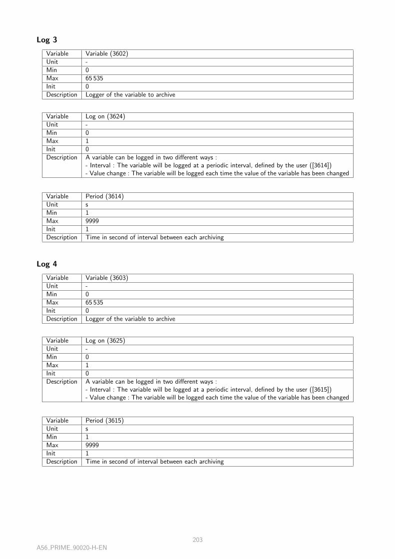
Log 3
Variable Variable (3602)Unit -Min 0Max 65 535Init 0Description Logger of the variable to archive
Variable Log on (3624)Unit -Min 0Max 1Init 0Description A variable can be logged in two different ways :
- Interval : The variable will be logged at a periodic interval, defined by the user ([3614])- Value change : The variable will be logged each time the value of the variable has been changed
Variable Period (3614)Unit sMin 1Max 9999Init 1Description Time in second of interval between each archiving
Log 4
Variable Variable (3603)Unit -Min 0Max 65 535Init 0Description Logger of the variable to archive
Variable Log on (3625)Unit -Min 0Max 1Init 0Description A variable can be logged in two different ways :
- Interval : The variable will be logged at a periodic interval, defined by the user ([3615])- Value change : The variable will be logged each time the value of the variable has been changed
Variable Period (3615)Unit sMin 1Max 9999Init 1Description Time in second of interval between each archiving
A56 PRIME 90020-H-EN203

Log 5
Variable Variable (3604)Unit -Min 0Max 65 535Init 0Description Logger of the variable to archive
Variable Log on (3626)Unit -Min 0Max 1Init 0Description A variable can be logged in two different ways :
- Interval : The variable will be logged at a periodic interval, defined by the user ([3616])- Value change : The variable will be logged each time the value of the variable has been changed
Variable Period (3616)Unit sMin 1Max 9999Init 1Description Time in second of interval between each archiving
Variables 6-10
Log 6
Variable Variable (3605)Unit -Min 0Max 65 535Init 0Description Logger of the variable to archive
Variable Log on (3627)Unit -Min 0Max 1Init 0Description A variable can be logged in two different ways :
- Interval : The variable will be logged at a periodic interval, defined by the user ([3617])- Value change : The variable will be logged each time the value of the variable has been changed
Variable Period (3617)Unit sMin 1Max 9999Init 1Description Time in second of interval between each archiving
A56 PRIME 90020-H-EN204

Log 7
Variable Variable (3606)Unit -Min 0Max 65 535Init 0Description Logger of the variable to archive
Variable Log on (3628)Unit -Min 0Max 1Init 0Description A variable can be logged in two different ways :
- Interval : The variable will be logged at a periodic interval, defined by the user ([3618])- Value change : The variable will be logged each time the value of the variable has been changed
Variable Period (3618)Unit sMin 1Max 9999Init 1Description Time in second of interval between each archiving
Log 8
Variable Variable (3607)Unit -Min 0Max 65 535Init 0Description Logger of the variable to archive
Variable Log on (3629)Unit -Min 0Max 1Init 0Description A variable can be logged in two different ways :
- Interval : The variable will be logged at a periodic interval, defined by the user ([3619])- Value change : The variable will be logged each time the value of the variable has been changed
Variable Period (3619)Unit sMin 1Max 9999Init 1Description Time in second of interval between each archiving
A56 PRIME 90020-H-EN205

Log 9
Variable Variable (3608)Unit -Min 0Max 65 535Init 0Description Logger of the variable to archive
Variable Log on (3630)Unit -Min 0Max 1Init 0Description A variable can be logged in two different ways :
- Interval : The variable will be logged at a periodic interval, defined by the user ([3620])- Value change : The variable will be logged each time the value of the variable has been changed
Variable Period (3620)Unit sMin 1Max 9999Init 1Description Time in second of interval between each archiving
Log 10
Variable Variable (3609)Unit -Min 0Max 65 535Init 0Description Logger of the variable to archive
Variable Log on (3631)Unit -Min 0Max 1Init 0Description A variable can be logged in two different ways :
- Interval : The variable will be logged at a periodic interval, defined by the user ([3621])- Value change : The variable will be logged each time the value of the variable has been changed
Variable Period (3621)Unit sMin 1Max 9999Init 1Description Time in second of interval between each archiving
A56 PRIME 90020-H-EN206
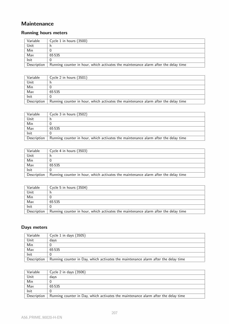
Maintenance
Running hours meters
Variable Cycle 1 in hours (3500)Unit hMin 0Max 65 535Init 0Description Running counter in hour, which activates the maintenance alarm after the delay time
Variable Cycle 2 in hours (3501)Unit hMin 0Max 65 535Init 0Description Running counter in hour, which activates the maintenance alarm after the delay time
Variable Cycle 3 in hours (3502)Unit hMin 0Max 65 535Init 0Description Running counter in hour, which activates the maintenance alarm after the delay time
Variable Cycle 4 in hours (3503)Unit hMin 0Max 65 535Init 0Description Running counter in hour, which activates the maintenance alarm after the delay time
Variable Cycle 5 in hours (3504)Unit hMin 0Max 65 535Init 0Description Running counter in hour, which activates the maintenance alarm after the delay time
Days meters
Variable Cycle 1 in days (3505)Unit daysMin 0Max 65 535Init 0Description Running counter in Day, which activates the maintenance alarm after the delay time
Variable Cycle 2 in days (3506)Unit daysMin 0Max 65 535Init 0Description Running counter in Day, which activates the maintenance alarm after the delay time
A56 PRIME 90020-H-EN207

Variable Cycle 3 in days (3507)Unit daysMin 0Max 65 535Init 0Description Running counter in Day, which activates the maintenance alarm after the delay time
Variable Cycle 4 in days (3508)Unit daysMin 0Max 65 535Init 0Description Running counter in Day, which activates the maintenance alarm after the delay time
Variable Cycle 5 in days (3509)Unit daysMin 0Max 65 535Init 0Description Running counter in Day, which activates the maintenance alarm after the delay time
Modbus redirection
Variable Modbus 000 (10000)Unit -Min 0Max 65 535Init 0Description Modbus redirection variable, allows to redirect a variable to the modbus address 10,000
A56 PRIME 90020-H-EN208

List of inputs/outputs - Bitfields
List of inputs 201Generator breaker feedback (4501) . . . . . . . . . . . . . . . . . . . . . . . . . . . . . . . . . . . . 201Remote start on load (4502) . . . . . . . . . . . . . . . . . . . . . . . . . . . . . . . . . . . . . . . 201Oil pressure fault (4503) . . . . . . . . . . . . . . . . . . . . . . . . . . . . . . . . . . . . . . . . . 201Coolant temperature fault (4504) . . . . . . . . . . . . . . . . . . . . . . . . . . . . . . . . . . . . . 201Emergency stop (4505) . . . . . . . . . . . . . . . . . . . . . . . . . . . . . . . . . . . . . . . . . . 201Fault reset (4506) . . . . . . . . . . . . . . . . . . . . . . . . . . . . . . . . . . . . . . . . . . . . . 201Generator fault request (4507) . . . . . . . . . . . . . . . . . . . . . . . . . . . . . . . . . . . . . . 201Manual start request (4509) . . . . . . . . . . . . . . . . . . . . . . . . . . . . . . . . . . . . . . . 201Manual stop request (4510) . . . . . . . . . . . . . . . . . . . . . . . . . . . . . . . . . . . . . . . . 201Manual mode request (4511) . . . . . . . . . . . . . . . . . . . . . . . . . . . . . . . . . . . . . . . 201Manual mode inhibition (4512) . . . . . . . . . . . . . . . . . . . . . . . . . . . . . . . . . . . . . . 201Auto mode request (4513) . . . . . . . . . . . . . . . . . . . . . . . . . . . . . . . . . . . . . . . . 201Increase speed in manual mode (4514) . . . . . . . . . . . . . . . . . . . . . . . . . . . . . . . . . . 201Decrease speed in manual mode (4515) . . . . . . . . . . . . . . . . . . . . . . . . . . . . . . . . . 201Increase voltage in manual mode (4516) . . . . . . . . . . . . . . . . . . . . . . . . . . . . . . . . . 201Decrease voltage in manual mode (4517) . . . . . . . . . . . . . . . . . . . . . . . . . . . . . . . . 202Generator breaker opening in manual mode (4518) . . . . . . . . . . . . . . . . . . . . . . . . . . . 202Generator breaker closing in manual mode (4520) . . . . . . . . . . . . . . . . . . . . . . . . . . . . 202Generator ready (4523) . . . . . . . . . . . . . . . . . . . . . . . . . . . . . . . . . . . . . . . . . . 202Start inhibition (4524) . . . . . . . . . . . . . . . . . . . . . . . . . . . . . . . . . . . . . . . . . . . 202Remote hard shut down (4525) . . . . . . . . . . . . . . . . . . . . . . . . . . . . . . . . . . . . . . 202Remote soft shut down (4526) . . . . . . . . . . . . . . . . . . . . . . . . . . . . . . . . . . . . . . 202Remote alarm (4527) . . . . . . . . . . . . . . . . . . . . . . . . . . . . . . . . . . . . . . . . . . . 202Remote Fault + Help (4528) . . . . . . . . . . . . . . . . . . . . . . . . . . . . . . . . . . . . . . . 202Remote soft shutdown + help (4529) . . . . . . . . . . . . . . . . . . . . . . . . . . . . . . . . . . 202Stop horn (4530) . . . . . . . . . . . . . . . . . . . . . . . . . . . . . . . . . . . . . . . . . . . . . 202Prelubrication request (4533) . . . . . . . . . . . . . . . . . . . . . . . . . . . . . . . . . . . . . . . 202Preglow request (4534) . . . . . . . . . . . . . . . . . . . . . . . . . . . . . . . . . . . . . . . . . . 202Speed setpoint 2 selection (4535) . . . . . . . . . . . . . . . . . . . . . . . . . . . . . . . . . . . . . 202Remote non essential load (4537) . . . . . . . . . . . . . . . . . . . . . . . . . . . . . . . . . . . . . 202Priority generator (4538) . . . . . . . . . . . . . . . . . . . . . . . . . . . . . . . . . . . . . . . . . 203Unload generator if load dependant start/stop rules OK (4543) . . . . . . . . . . . . . . . . . . . . . 203Alternative selection 1 (4594) . . . . . . . . . . . . . . . . . . . . . . . . . . . . . . . . . . . . . . . 203Alternative selection 2 (4595) . . . . . . . . . . . . . . . . . . . . . . . . . . . . . . . . . . . . . . . 203Alternative selection 3 (4596) . . . . . . . . . . . . . . . . . . . . . . . . . . . . . . . . . . . . . . . 203Alternative selection 4 (4597) . . . . . . . . . . . . . . . . . . . . . . . . . . . . . . . . . . . . . . . 203Alternative selection 5 (4598) . . . . . . . . . . . . . . . . . . . . . . . . . . . . . . . . . . . . . . . 203Alternative selection 6 (4599) . . . . . . . . . . . . . . . . . . . . . . . . . . . . . . . . . . . . . . . 203Alternative selection 7 (4600) . . . . . . . . . . . . . . . . . . . . . . . . . . . . . . . . . . . . . . . 203Alternative selection 8 (4601) . . . . . . . . . . . . . . . . . . . . . . . . . . . . . . . . . . . . . . . 203Alternative selection 9 (4602) . . . . . . . . . . . . . . . . . . . . . . . . . . . . . . . . . . . . . . . 203Alternative selection 10 (4603) . . . . . . . . . . . . . . . . . . . . . . . . . . . . . . . . . . . . . . 203Alternative selection 11 (4604) . . . . . . . . . . . . . . . . . . . . . . . . . . . . . . . . . . . . . . 203Alternative selection 12 (4605) . . . . . . . . . . . . . . . . . . . . . . . . . . . . . . . . . . . . . . 203Alternative selection 13 (4606) . . . . . . . . . . . . . . . . . . . . . . . . . . . . . . . . . . . . . . 203Alternative selection 14 (4607) . . . . . . . . . . . . . . . . . . . . . . . . . . . . . . . . . . . . . . 203Alternative selection 15 (4608) . . . . . . . . . . . . . . . . . . . . . . . . . . . . . . . . . . . . . . 204Alternative selection 16 (4609) . . . . . . . . . . . . . . . . . . . . . . . . . . . . . . . . . . . . . . 204Override (NFE37312) (4610) . . . . . . . . . . . . . . . . . . . . . . . . . . . . . . . . . . . . . . . 204Remote start off load (4611) . . . . . . . . . . . . . . . . . . . . . . . . . . . . . . . . . . . . . . . 204Remote start with timer (4612) . . . . . . . . . . . . . . . . . . . . . . . . . . . . . . . . . . . . . . 204Hysteresis low threshold DI1 (4614) . . . . . . . . . . . . . . . . . . . . . . . . . . . . . . . . . . . 204Hysteresis low threshold DI2 (4615) . . . . . . . . . . . . . . . . . . . . . . . . . . . . . . . . . . . 204Hysteresis low threshold DI3 (4616) . . . . . . . . . . . . . . . . . . . . . . . . . . . . . . . . . . . 204Hysteresis low threshold DI4 (4617) . . . . . . . . . . . . . . . . . . . . . . . . . . . . . . . . . . . 204Hysteresis low threshold DI5 (4618) . . . . . . . . . . . . . . . . . . . . . . . . . . . . . . . . . . . 204Hysteresis low threshold DI6 (4619) . . . . . . . . . . . . . . . . . . . . . . . . . . . . . . . . . . . 204
A56 PRIME 90020-H-EN209

Hysteresis low threshold DI7 (4620) . . . . . . . . . . . . . . . . . . . . . . . . . . . . . . . . . . . 204Hysteresis low threshold DI8 (4621) . . . . . . . . . . . . . . . . . . . . . . . . . . . . . . . . . . . 204Hysteresis high threshold DI1 (4622) . . . . . . . . . . . . . . . . . . . . . . . . . . . . . . . . . . . 204Hysteresis high threshold DI2 (4623) . . . . . . . . . . . . . . . . . . . . . . . . . . . . . . . . . . . 204Hysteresis high threshold DI3 (4624) . . . . . . . . . . . . . . . . . . . . . . . . . . . . . . . . . . . 204Hysteresis high threshold DI4 (4625) . . . . . . . . . . . . . . . . . . . . . . . . . . . . . . . . . . . 205Hysteresis high threshold DI5 (4626) . . . . . . . . . . . . . . . . . . . . . . . . . . . . . . . . . . . 205Hysteresis high threshold DI6 (4627) . . . . . . . . . . . . . . . . . . . . . . . . . . . . . . . . . . . 205Hysteresis high threshold DI7 (4628) . . . . . . . . . . . . . . . . . . . . . . . . . . . . . . . . . . . 205Hysteresis high threshold DI8 (4629) . . . . . . . . . . . . . . . . . . . . . . . . . . . . . . . . . . . 205Digital output 1 forced (4630) . . . . . . . . . . . . . . . . . . . . . . . . . . . . . . . . . . . . . . 205Digital output 2 forced (4631) . . . . . . . . . . . . . . . . . . . . . . . . . . . . . . . . . . . . . . 205Digital output 3 forced (4632) . . . . . . . . . . . . . . . . . . . . . . . . . . . . . . . . . . . . . . 205Digital output 4 forced (4633) . . . . . . . . . . . . . . . . . . . . . . . . . . . . . . . . . . . . . . 205Digital output 5 forced (4634) . . . . . . . . . . . . . . . . . . . . . . . . . . . . . . . . . . . . . . 205Digital output 6 forced (4635) . . . . . . . . . . . . . . . . . . . . . . . . . . . . . . . . . . . . . . 205Relay 1 forced (4950) . . . . . . . . . . . . . . . . . . . . . . . . . . . . . . . . . . . . . . . . . . . 205Relay 2 forced (4951) . . . . . . . . . . . . . . . . . . . . . . . . . . . . . . . . . . . . . . . . . . . 205
List of outputs 206Dead bus bar (124) . . . . . . . . . . . . . . . . . . . . . . . . . . . . . . . . . . . . . . . . . . . . 206Phase sequence match (306) . . . . . . . . . . . . . . . . . . . . . . . . . . . . . . . . . . . . . . . 206Voltage match (307) . . . . . . . . . . . . . . . . . . . . . . . . . . . . . . . . . . . . . . . . . . . 206Frequency match (308) . . . . . . . . . . . . . . . . . . . . . . . . . . . . . . . . . . . . . . . . . . 206Phase match (309) . . . . . . . . . . . . . . . . . . . . . . . . . . . . . . . . . . . . . . . . . . . . 206Authorization to close breaker (310) . . . . . . . . . . . . . . . . . . . . . . . . . . . . . . . . . . . 206Isolated product (sees nothing on CAN bus) (600) . . . . . . . . . . . . . . . . . . . . . . . . . . . . 206Missing product (atleast one product is missing on CAN bus) (605) . . . . . . . . . . . . . . . . . . 206Missing MASTER (608) . . . . . . . . . . . . . . . . . . . . . . . . . . . . . . . . . . . . . . . . . . 206J1939 Fault (650) . . . . . . . . . . . . . . . . . . . . . . . . . . . . . . . . . . . . . . . . . . . . . 206J1939 : High Water temperature alarm (652) . . . . . . . . . . . . . . . . . . . . . . . . . . . . . . 206J1939 : High Water temperature fault (653) . . . . . . . . . . . . . . . . . . . . . . . . . . . . . . . 206J1939 : Low oil pressure alarm (654) . . . . . . . . . . . . . . . . . . . . . . . . . . . . . . . . . . . 206J1939 : Low oil pressure fault (655) . . . . . . . . . . . . . . . . . . . . . . . . . . . . . . . . . . . 206J1939 : Overspeed alarm (656) . . . . . . . . . . . . . . . . . . . . . . . . . . . . . . . . . . . . . . 206J1939 : Overspeed fault (657) . . . . . . . . . . . . . . . . . . . . . . . . . . . . . . . . . . . . . . 207DM1 engine protection (658) . . . . . . . . . . . . . . . . . . . . . . . . . . . . . . . . . . . . . . . 207DM1 warning (659) . . . . . . . . . . . . . . . . . . . . . . . . . . . . . . . . . . . . . . . . . . . . 207DM1 alarm (660) . . . . . . . . . . . . . . . . . . . . . . . . . . . . . . . . . . . . . . . . . . . . . 207DM1 malfunction (661) . . . . . . . . . . . . . . . . . . . . . . . . . . . . . . . . . . . . . . . . . . 207Start request (4006) . . . . . . . . . . . . . . . . . . . . . . . . . . . . . . . . . . . . . . . . . . . . 207Production request (4007) . . . . . . . . . . . . . . . . . . . . . . . . . . . . . . . . . . . . . . . . 207Fail to synchronize (4051) . . . . . . . . . . . . . . . . . . . . . . . . . . . . . . . . . . . . . . . . . 207Unload request (4104) . . . . . . . . . . . . . . . . . . . . . . . . . . . . . . . . . . . . . . . . . . . 207Load request (4105) . . . . . . . . . . . . . . . . . . . . . . . . . . . . . . . . . . . . . . . . . . . . 207Breaker fault (4152) . . . . . . . . . . . . . . . . . . . . . . . . . . . . . . . . . . . . . . . . . . . . 207Breaker alarm (4153) . . . . . . . . . . . . . . . . . . . . . . . . . . . . . . . . . . . . . . . . . . . 207Fail to close generator breaker (4154) . . . . . . . . . . . . . . . . . . . . . . . . . . . . . . . . . . 207Fail to open generator breaker (4155) . . . . . . . . . . . . . . . . . . . . . . . . . . . . . . . . . . 207Generator breaker open suddently (4156) . . . . . . . . . . . . . . . . . . . . . . . . . . . . . . . . . 207Generator breaker close suddently (4170) . . . . . . . . . . . . . . . . . . . . . . . . . . . . . . . . . 207Engine over speed (4200) . . . . . . . . . . . . . . . . . . . . . . . . . . . . . . . . . . . . . . . . . 208Engine under speed (4201) . . . . . . . . . . . . . . . . . . . . . . . . . . . . . . . . . . . . . . . . 208Battery minimum voltage (4202) . . . . . . . . . . . . . . . . . . . . . . . . . . . . . . . . . . . . . 208Battery maximum voltage (4203) . . . . . . . . . . . . . . . . . . . . . . . . . . . . . . . . . . . . . 208Engine minimum oil pressure (4204) . . . . . . . . . . . . . . . . . . . . . . . . . . . . . . . . . . . 208Engine maximum water temperature (4205) . . . . . . . . . . . . . . . . . . . . . . . . . . . . . . . 208AN1 min/max (Customisable) (4206) . . . . . . . . . . . . . . . . . . . . . . . . . . . . . . . . . . 208AN2 min/max (Customisable) (4207) . . . . . . . . . . . . . . . . . . . . . . . . . . . . . . . . . . 208AN3 min/max (Customisable) (4208) . . . . . . . . . . . . . . . . . . . . . . . . . . . . . . . . . . 208Minimum speed output (4209) . . . . . . . . . . . . . . . . . . . . . . . . . . . . . . . . . . . . . . 208
A56 PRIME 90020-H-EN210

Maximum speed output (4210) . . . . . . . . . . . . . . . . . . . . . . . . . . . . . . . . . . . . . . 208Minimum AVR output (4211) . . . . . . . . . . . . . . . . . . . . . . . . . . . . . . . . . . . . . . . 208Maximum AVR output (4212) . . . . . . . . . . . . . . . . . . . . . . . . . . . . . . . . . . . . . . 208Generator over frequency (4250) . . . . . . . . . . . . . . . . . . . . . . . . . . . . . . . . . . . . . 208Generator under frequency (4251) . . . . . . . . . . . . . . . . . . . . . . . . . . . . . . . . . . . . 209Generator over voltage (4252) . . . . . . . . . . . . . . . . . . . . . . . . . . . . . . . . . . . . . . 209Generator under voltage (4253) . . . . . . . . . . . . . . . . . . . . . . . . . . . . . . . . . . . . . . 209Generator minimum KW (4254) . . . . . . . . . . . . . . . . . . . . . . . . . . . . . . . . . . . . . 209Generator maximum KW (4255) . . . . . . . . . . . . . . . . . . . . . . . . . . . . . . . . . . . . . 209Generator reverse KW (4256) . . . . . . . . . . . . . . . . . . . . . . . . . . . . . . . . . . . . . . . 209Generator minimum KVAR (4257) . . . . . . . . . . . . . . . . . . . . . . . . . . . . . . . . . . . . 209Generator maximum KVAR (4258) . . . . . . . . . . . . . . . . . . . . . . . . . . . . . . . . . . . . 209Generator reverse KVAR (4259) . . . . . . . . . . . . . . . . . . . . . . . . . . . . . . . . . . . . . . 209Generator maximum current (4260) . . . . . . . . . . . . . . . . . . . . . . . . . . . . . . . . . . . 209Generator maximum neutral current (4261) . . . . . . . . . . . . . . . . . . . . . . . . . . . . . . . 209Generator short-circuit (4262) . . . . . . . . . . . . . . . . . . . . . . . . . . . . . . . . . . . . . . . 209Uneven kW sharing fault (4263) . . . . . . . . . . . . . . . . . . . . . . . . . . . . . . . . . . . . . 209Uneven kVAR sharing fault (4264) . . . . . . . . . . . . . . . . . . . . . . . . . . . . . . . . . . . . 209Generator earth fault current (4267) . . . . . . . . . . . . . . . . . . . . . . . . . . . . . . . . . . . 209Generator voltage unbalance (4268) . . . . . . . . . . . . . . . . . . . . . . . . . . . . . . . . . . . 209Generator current unbalance (4269) . . . . . . . . . . . . . . . . . . . . . . . . . . . . . . . . . . . 210Bus measure error (4315) . . . . . . . . . . . . . . . . . . . . . . . . . . . . . . . . . . . . . . . . . 210Fail to stop engine (4472) . . . . . . . . . . . . . . . . . . . . . . . . . . . . . . . . . . . . . . . . . 210Engine not ready (4473) . . . . . . . . . . . . . . . . . . . . . . . . . . . . . . . . . . . . . . . . . 210Engine fault (4474) . . . . . . . . . . . . . . . . . . . . . . . . . . . . . . . . . . . . . . . . . . . . 210Fail to start engine (4475) . . . . . . . . . . . . . . . . . . . . . . . . . . . . . . . . . . . . . . . . 210Order to close generator breaker (4650) . . . . . . . . . . . . . . . . . . . . . . . . . . . . . . . . . 210Starter n°1 (4652) . . . . . . . . . . . . . . . . . . . . . . . . . . . . . . . . . . . . . . . . . . . . . 210Starter n°2 (4653) . . . . . . . . . . . . . . . . . . . . . . . . . . . . . . . . . . . . . . . . . . . . . 210Starter n°3 (4654) . . . . . . . . . . . . . . . . . . . . . . . . . . . . . . . . . . . . . . . . . . . . . 210Fuel / Gas (4655) . . . . . . . . . . . . . . . . . . . . . . . . . . . . . . . . . . . . . . . . . . . . . 210Generator electrical faults summary (4656) . . . . . . . . . . . . . . . . . . . . . . . . . . . . . . . . 210Alarms summary (4658) . . . . . . . . . . . . . . . . . . . . . . . . . . . . . . . . . . . . . . . . . . 210Soft shut down summary (4659) . . . . . . . . . . . . . . . . . . . . . . . . . . . . . . . . . . . . . 210Hard shut down summary (4660) . . . . . . . . . . . . . . . . . . . . . . . . . . . . . . . . . . . . . 210Soft shut down + Help (4661) . . . . . . . . . . . . . . . . . . . . . . . . . . . . . . . . . . . . . . 210Generator electrical faults + Help (4662) . . . . . . . . . . . . . . . . . . . . . . . . . . . . . . . . . 211Horn (4663) . . . . . . . . . . . . . . . . . . . . . . . . . . . . . . . . . . . . . . . . . . . . . . . . 211Default LED (4664) . . . . . . . . . . . . . . . . . . . . . . . . . . . . . . . . . . . . . . . . . . . . 211Alarm LED (4665) . . . . . . . . . . . . . . . . . . . . . . . . . . . . . . . . . . . . . . . . . . . . . 211Automatic mode LED (4666) . . . . . . . . . . . . . . . . . . . . . . . . . . . . . . . . . . . . . . . 211Test mode LED (4667) . . . . . . . . . . . . . . . . . . . . . . . . . . . . . . . . . . . . . . . . . . 211Manual mode LED (4668) . . . . . . . . . . . . . . . . . . . . . . . . . . . . . . . . . . . . . . . . 211Generator LED (4669) . . . . . . . . . . . . . . . . . . . . . . . . . . . . . . . . . . . . . . . . . . . 211Generator ready (4670) . . . . . . . . . . . . . . . . . . . . . . . . . . . . . . . . . . . . . . . . . . 211Generator voltage present (4671) . . . . . . . . . . . . . . . . . . . . . . . . . . . . . . . . . . . . . 211Generator active power flow (4672) . . . . . . . . . . . . . . . . . . . . . . . . . . . . . . . . . . . . 211Generator stop (4673) . . . . . . . . . . . . . . . . . . . . . . . . . . . . . . . . . . . . . . . . . . . 211Energize to stop (4674) . . . . . . . . . . . . . . . . . . . . . . . . . . . . . . . . . . . . . . . . . . 211Generator breaker close (4675) . . . . . . . . . . . . . . . . . . . . . . . . . . . . . . . . . . . . . . 211Generator breaker open (4677) . . . . . . . . . . . . . . . . . . . . . . . . . . . . . . . . . . . . . . 211Mains breaker open (4678) . . . . . . . . . . . . . . . . . . . . . . . . . . . . . . . . . . . . . . . . 212Available in automatic (4679) . . . . . . . . . . . . . . . . . . . . . . . . . . . . . . . . . . . . . . . 212Excitation command (4680) . . . . . . . . . . . . . . . . . . . . . . . . . . . . . . . . . . . . . . . . 212Protection valid (4681) . . . . . . . . . . . . . . . . . . . . . . . . . . . . . . . . . . . . . . . . . . 212Prelubrication (4684) . . . . . . . . . . . . . . . . . . . . . . . . . . . . . . . . . . . . . . . . . . . 212Preglow (4685) . . . . . . . . . . . . . . . . . . . . . . . . . . . . . . . . . . . . . . . . . . . . . . 212Smoke limit / Position limiting (4686) . . . . . . . . . . . . . . . . . . . . . . . . . . . . . . . . . . 212Damper (4687) . . . . . . . . . . . . . . . . . . . . . . . . . . . . . . . . . . . . . . . . . . . . . . 212Air conditionning (4688) . . . . . . . . . . . . . . . . . . . . . . . . . . . . . . . . . . . . . . . . . 2121st non essential trip (4689) . . . . . . . . . . . . . . . . . . . . . . . . . . . . . . . . . . . . . . . 212
A56 PRIME 90020-H-EN211

2nd non essential trip (4690) . . . . . . . . . . . . . . . . . . . . . . . . . . . . . . . . . . . . . . . 2123rd non essential trip (4691) . . . . . . . . . . . . . . . . . . . . . . . . . . . . . . . . . . . . . . . 2124th non essential trip (4692) . . . . . . . . . . . . . . . . . . . . . . . . . . . . . . . . . . . . . . . 2125th non essential trip (4693) . . . . . . . . . . . . . . . . . . . . . . . . . . . . . . . . . . . . . . . 212Non essential direct trip (4694) . . . . . . . . . . . . . . . . . . . . . . . . . . . . . . . . . . . . . . 212Increase speed by pulse (4699) . . . . . . . . . . . . . . . . . . . . . . . . . . . . . . . . . . . . . . 213Decrease speed by pulse (4700) . . . . . . . . . . . . . . . . . . . . . . . . . . . . . . . . . . . . . . 213Increase voltage by pulse (4701) . . . . . . . . . . . . . . . . . . . . . . . . . . . . . . . . . . . . . 213Decrease voltage by pulse (4702) . . . . . . . . . . . . . . . . . . . . . . . . . . . . . . . . . . . . . 213Idle speed (4704) . . . . . . . . . . . . . . . . . . . . . . . . . . . . . . . . . . . . . . . . . . . . . 213Ignition (4707) . . . . . . . . . . . . . . . . . . . . . . . . . . . . . . . . . . . . . . . . . . . . . . . 213Inhibited faults summary (NFE 37-312) (4708) . . . . . . . . . . . . . . . . . . . . . . . . . . . . . 213Battery boost DO (4709) . . . . . . . . . . . . . . . . . . . . . . . . . . . . . . . . . . . . . . . . . 213Hysteresis output activation on AI1 (4710) . . . . . . . . . . . . . . . . . . . . . . . . . . . . . . . . 213Hysteresis output activation on AI2 (4711) . . . . . . . . . . . . . . . . . . . . . . . . . . . . . . . . 213Hysteresis output activation on AI3 (4712) . . . . . . . . . . . . . . . . . . . . . . . . . . . . . . . . 213Hysteresis output activation on DI1 (4713) . . . . . . . . . . . . . . . . . . . . . . . . . . . . . . . . 213Hysteresis output activation on DI2 (4714) . . . . . . . . . . . . . . . . . . . . . . . . . . . . . . . . 213Hysteresis output activation on DI3 (4715) . . . . . . . . . . . . . . . . . . . . . . . . . . . . . . . . 213Hysteresis output activation on DI4 (4716) . . . . . . . . . . . . . . . . . . . . . . . . . . . . . . . . 213Hysteresis output activation on DI5 (4717) . . . . . . . . . . . . . . . . . . . . . . . . . . . . . . . . 214Hysteresis output activation on DI6 (4718) . . . . . . . . . . . . . . . . . . . . . . . . . . . . . . . . 214Hysteresis output activation on DI7 (4719) . . . . . . . . . . . . . . . . . . . . . . . . . . . . . . . . 214Hysteresis output activation on DI8 (4720) . . . . . . . . . . . . . . . . . . . . . . . . . . . . . . . . 214CANopen fault (4750) . . . . . . . . . . . . . . . . . . . . . . . . . . . . . . . . . . . . . . . . . . . 214
Bitfields 215SYSTEM INFO (E00950) . . . . . . . . . . . . . . . . . . . . . . . . . . . . . . . . . . . . . . . . . 215KEY INHIBITION STATUS (E00951) . . . . . . . . . . . . . . . . . . . . . . . . . . . . . . . . . . 215LED STATUS (E00952) . . . . . . . . . . . . . . . . . . . . . . . . . . . . . . . . . . . . . . . . . . 215Digital input raw (E00953) . . . . . . . . . . . . . . . . . . . . . . . . . . . . . . . . . . . . . . . . 216E00954 (Processed) . . . . . . . . . . . . . . . . . . . . . . . . . . . . . . . . . . . . . . . . . . . . 216E00955 (Processed) . . . . . . . . . . . . . . . . . . . . . . . . . . . . . . . . . . . . . . . . . . . . 216E00956 (Processed) . . . . . . . . . . . . . . . . . . . . . . . . . . . . . . . . . . . . . . . . . . . . 217E00957 (Processed) . . . . . . . . . . . . . . . . . . . . . . . . . . . . . . . . . . . . . . . . . . . . 217E00958 (Processed) . . . . . . . . . . . . . . . . . . . . . . . . . . . . . . . . . . . . . . . . . . . . 217E00959 (Processed) . . . . . . . . . . . . . . . . . . . . . . . . . . . . . . . . . . . . . . . . . . . . 218RESET MAINTENANCE & METERS (E10400) . . . . . . . . . . . . . . . . . . . . . . . . . . . . . 218RESET MAINTENANCE & METERS 2 (E10401) . . . . . . . . . . . . . . . . . . . . . . . . . . . . 218KEY INHIBITION (E8102) . . . . . . . . . . . . . . . . . . . . . . . . . . . . . . . . . . . . . . . . 219MODBUS ACCESS (E3015) . . . . . . . . . . . . . . . . . . . . . . . . . . . . . . . . . . . . . . . 219E00960 (Alarm) . . . . . . . . . . . . . . . . . . . . . . . . . . . . . . . . . . . . . . . . . . . . . . 219E00961 (Fault) . . . . . . . . . . . . . . . . . . . . . . . . . . . . . . . . . . . . . . . . . . . . . . 220E00962 (Alarm) . . . . . . . . . . . . . . . . . . . . . . . . . . . . . . . . . . . . . . . . . . . . . . 220E00963 (Fault) . . . . . . . . . . . . . . . . . . . . . . . . . . . . . . . . . . . . . . . . . . . . . . 220E00964 (Alarm) . . . . . . . . . . . . . . . . . . . . . . . . . . . . . . . . . . . . . . . . . . . . . . 221E00965 (Fault) . . . . . . . . . . . . . . . . . . . . . . . . . . . . . . . . . . . . . . . . . . . . . . 221E00966 (Alarm) . . . . . . . . . . . . . . . . . . . . . . . . . . . . . . . . . . . . . . . . . . . . . . 221E00967 (Fault) . . . . . . . . . . . . . . . . . . . . . . . . . . . . . . . . . . . . . . . . . . . . . . 222E00968 (Alarm) . . . . . . . . . . . . . . . . . . . . . . . . . . . . . . . . . . . . . . . . . . . . . . 222E00969 (Fault) . . . . . . . . . . . . . . . . . . . . . . . . . . . . . . . . . . . . . . . . . . . . . . 222E00970 (Alarm) . . . . . . . . . . . . . . . . . . . . . . . . . . . . . . . . . . . . . . . . . . . . . . 223E00971 (Fault) . . . . . . . . . . . . . . . . . . . . . . . . . . . . . . . . . . . . . . . . . . . . . . 223E00972 (Alarm) . . . . . . . . . . . . . . . . . . . . . . . . . . . . . . . . . . . . . . . . . . . . . . 223E00973 (Fault) . . . . . . . . . . . . . . . . . . . . . . . . . . . . . . . . . . . . . . . . . . . . . . 224E00974 (Alarm) . . . . . . . . . . . . . . . . . . . . . . . . . . . . . . . . . . . . . . . . . . . . . . 224E00975 (Fault) . . . . . . . . . . . . . . . . . . . . . . . . . . . . . . . . . . . . . . . . . . . . . . 224
A56 PRIME 90020-H-EN212

List of inputs
Variable Generator breaker feedback (4501)Description Generator breaker position feedback
Variable Remote start on load (4502)Description Allows to start and close the generator breaker on load in auto mode
Variable Oil pressure fault (4503)Description External oil pressure monitoring
Variable Coolant temperature fault (4504)Description External temperature monitoring (when the coolant is not water)
Variable Emergency stop (4505)Description Remote stop of generator
Variable Fault reset (4506)Description External reset. Alternative to local fault reset in Fault and Alarm pages.
Variable Generator fault request (4507)Description Fault raised by the generator
Variable Manual start request (4509)Description Remote start command (alternative to front button)
Variable Manual stop request (4510)Description Remote stop command (alternative to front button)
Variable Manual mode request (4511)Description Puts the product into manual mode, same effect as MAN key
Variable Manual mode inhibition (4512)Description Inhibits manual mode (Remote or front panel)
Variable Auto mode request (4513)Description Auto mode external request
Variable Increase speed in manual mode (4514)Description Remote frequency increase command (alternative to front button)
Variable Decrease speed in manual mode (4515)Description Remote frequency decrease command (alternative to front button)
Variable Increase voltage in manual mode (4516)Description Remote voltage increase command (alternative to front button)
A56 PRIME 90020-H-EN213

Variable Decrease voltage in manual mode (4517)Description Remote voltage decrease command (alternative to front button)
Variable Generator breaker opening in manual mode (4518)Description Remote manual opening of generator breaker in manual mode (alternative to front button)
Variable Generator breaker closing in manual mode (4520)Description Remote manual close of generator breaker in manual mode (alternative to front button)
Variable Generator ready (4523)Description External start module declares the generator is ready
Variable Start inhibition (4524)Description Prevents engine from starting
Variable Remote hard shut down (4525)Description Immediate stop of the engine by external protections
Variable Remote soft shut down (4526)Description Immediate opening of generator breaker by external protections and stopping of the engine after
cooling down time has expired
Variable Remote alarm (4527)Description If external protections are installed, to report an alarm
Variable Remote Fault + Help (4528)Description Activates the ”Generator electrical fault” action. The product requires another engine to start
before stopping itself.
Variable Remote soft shutdown + help (4529)Description Stops the engine immediately.
Variable Stop horn (4530)Description Selective external reset, in addition, an output must be preset to Horn.
Variable Prelubrication request (4533)Description Prelubrication request
Variable Preglow request (4534)Description Preglow request
Variable Speed setpoint 2 selection (4535)Description Speed setpoint 2 selection
Variable Remote non essential load (4537)Description Order to switch on the load shedding.
A56 PRIME 90020-H-EN214

Variable Priority generator (4538)Description In power management, start-stop depends on a priority generator
Variable Unload generator if load dependant start/stop rules OK (4543)Description Logic input to stop the engine if load dependant start/stop rules are OK
Variable Alternative selection 1 (4594)Description 1st available variable to switch a parameter between 2 values
Variable Alternative selection 2 (4595)Description 2nd available variable to switch a parameter between 2 values
Variable Alternative selection 3 (4596)Description 3rd available variable to switch a parameter between 2 values
Variable Alternative selection 4 (4597)Description 4th available variable to switch a parameter between 2 values
Variable Alternative selection 5 (4598)Description 5th available variable to switch a parameter between 2 values
Variable Alternative selection 6 (4599)Description 6th available variable to switch a parameter between 2 values
Variable Alternative selection 7 (4600)Description 7th available variable to switch a parameter between 2 values
Variable Alternative selection 8 (4601)Description 8th available variable to switch a parameter between 2 values
Variable Alternative selection 9 (4602)Description 9th available variable to switch a parameter between 2 values
Variable Alternative selection 10 (4603)Description 10th available variable to switch a parameter between 2 values
Variable Alternative selection 11 (4604)Description 11th available variable to switch a parameter between 2 values
Variable Alternative selection 12 (4605)Description 12th available variable to switch a parameter between 2 values
Variable Alternative selection 13 (4606)Description 13th available variable to switch a parameter between 2 values
Variable Alternative selection 14 (4607)Description 14th available variable to switch a parameter between 2 values
A56 PRIME 90020-H-EN215

Variable Alternative selection 15 (4608)Description 15th available variable to switch a parameter between 2 values
Variable Alternative selection 16 (4609)Description 16th available variable to switch a parameter between 2 values
Variable Override (NFE37312) (4610)Description Override (NFE 37-312)
Variable Remote start off load (4611)Description Remote start off load
Variable Remote start with timer (4612)Description Remote start with timer
Variable Hysteresis low threshold DI1 (4614)Description Digital input : Low threshold 1
Variable Hysteresis low threshold DI2 (4615)Description Digital input : Low threshold 2
Variable Hysteresis low threshold DI3 (4616)Description Digital input : Low threshold 3
Variable Hysteresis low threshold DI4 (4617)Description Digital input : Low threshold 4
Variable Hysteresis low threshold DI5 (4618)Description Digital input : Low threshold 5
Variable Hysteresis low threshold DI6 (4619)Description Digital input : Low threshold 6
Variable Hysteresis low threshold DI7 (4620)Description Digital input : Low threshold 7
Variable Hysteresis low threshold DI8 (4621)Description Digital input : Low threshold 8
Variable Hysteresis high threshold DI1 (4622)Description Digital input : High threshold 1
Variable Hysteresis high threshold DI2 (4623)Description Digital input : High threshold 2
Variable Hysteresis high threshold DI3 (4624)Description Digital input : High threshold 3
A56 PRIME 90020-H-EN216

Variable Hysteresis high threshold DI4 (4625)Description Digital input : High threshold 4
Variable Hysteresis high threshold DI5 (4626)Description Digital input : High threshold 5
Variable Hysteresis high threshold DI6 (4627)Description Digital input : High threshold 6
Variable Hysteresis high threshold DI7 (4628)Description Digital input : High threshold 7
Variable Hysteresis high threshold DI8 (4629)Description Digital input : High threshold 8
Variable Digital output 1 forced (4630)Description Digital output 1 forced
Variable Digital output 2 forced (4631)Description Digital output 2 forced
Variable Digital output 3 forced (4632)Description Digital output 3 forced
Variable Digital output 4 forced (4633)Description Digital output 4 forced
Variable Digital output 5 forced (4634)Description Digital output 5 forced
Variable Digital output 6 forced (4635)Description Digital output 6 forced
Variable Relay 1 forced (4950)Description Relay 1 forced
Variable Relay 2 forced (4951)Description Relay 2 forced
A56 PRIME 90020-H-EN217

List of outputs
Variable Dead bus bar (124)Description Dead Bus Bar
Variable Phase sequence match (306)Description Phase sequences are the same for synchronization (OK = 1 or Not OK = 0)
Variable Voltage match (307)Description Voltages are close enough for synchronization (OK = 1 or Not OK = 0)
Variable Frequency match (308)Description Frequencies are close enough for synchronization (OK = 1 or Not OK = 0)
Variable Phase match (309)Description Phases are close enough for synchronization (OK = 1 or Not OK = 0)
Variable Authorization to close breaker (310)Description Synchronization request accepted (OK = 1 or Not OK = 0)
Variable Isolated product (sees nothing on CAN bus) (600)Description Isolated product (Product alone on the bus CAN)
Variable Missing product (atleast one product is missing on CAN bus) (605)Description Missing product (One or several procucts are missing)
Variable Missing MASTER (608)Description Missing MASTER
Variable J1939 Fault (650)Description J1939 Fault
Variable J1939 : High Water temperature alarm (652)Description High Water temperature alarm
Variable J1939 : High Water temperature fault (653)Description High Water temperature fault
Variable J1939 : Low oil pressure alarm (654)Description Low oil pressure alarm
Variable J1939 : Low oil pressure fault (655)Description Low oil pressure fault
Variable J1939 : Overspeed alarm (656)Description Overspeed alarm
A56 PRIME 90020-H-EN218

Variable J1939 : Overspeed fault (657)Description Overspeed fault
Variable DM1 engine protection (658)Description Protect Lamp Status (PGN : 65226 / SPN : 1213)
Variable DM1 warning (659)Description AL Combined Alarm Yellow (PGN : 65226 / SPN : 624)
Variable DM1 alarm (660)Description AL Combined Alarm Red (PGN : 65226 / SPN : 623)
Variable DM1 malfunction (661)Description Malfunction Indicator Lamp Status (PGN : 65226 / SPN : 1213)
Variable Start request (4006)Description The generator has received a remote start and forwards it to ASM
Variable Production request (4007)Description The generator has been elected to start
Variable Fail to synchronize (4051)Description Synchronization request denied (PID setting, fail to close breaker)
Variable Unload request (4104)Description Unload request
Variable Load request (4105)Description Load/ start request
Variable Breaker fault (4152)Description Control a breaker fault
Variable Breaker alarm (4153)Description Control a breaker alarm
Variable Fail to close generator breaker (4154)Description Fail to close generator breaker
Variable Fail to open generator breaker (4155)Description Fail to open generator breaker
Variable Generator breaker open suddently (4156)Description Generator breaker open suddenly
Variable Generator breaker close suddently (4170)Description Generator breaker close suddently
A56 PRIME 90020-H-EN219

Variable Engine over speed (4200)Description Engine over speed
Variable Engine under speed (4201)Description Engine under speed
Variable Battery minimum voltage (4202)Description Battery min volt
Variable Battery maximum voltage (4203)Description Battery max Volt
Variable Engine minimum oil pressure (4204)Description Engine minimum oil pressure
Variable Engine maximum water temperature (4205)Description Engine maximum water temperature
Variable AN1 min/max (Customisable) (4206)Description This value is to customize the label of analog input 1 protection.
The maximum number of caracters is of 14.This protection use the analog input 1 set in the ”Analog inputs” chapiter (variable 150).
Variable AN2 min/max (Customisable) (4207)Description This value is to customize the label of analog input 2 protection.
The maximum number of caracters is of 14.This protection use the analog input 2 set in the ”Analog inputs” chapiter (variable 151).
Variable AN3 min/max (Customisable) (4208)Description This value is to customize the label of analog input 3 protection.
The maximum number of caracters is of 14.This protection use the analog input 3 set in the ”Analog inputs” chapiter (variable 152).
Variable Minimum speed output (4209)Description Minimum speed output
Variable Maximum speed output (4210)Description Maximum speed output
Variable Minimum AVR output (4211)Description Minimum AVR output
Variable Maximum AVR output (4212)Description Maximum AVR output
Variable Generator over frequency (4250)Description Generator over frequency
A56 PRIME 90020-H-EN220

Variable Generator under frequency (4251)Description Generator under frequency
Variable Generator over voltage (4252)Description Generator over voltage
Variable Generator under voltage (4253)Description Generator under voltage
Variable Generator minimum KW (4254)Description Generator min KW
Variable Generator maximum KW (4255)Description Generator max KW
Variable Generator reverse KW (4256)Description Generator reverse KW
Variable Generator minimum KVAR (4257)Description Generator min KVAR
Variable Generator maximum KVAR (4258)Description Generator max KVAR
Variable Generator reverse KVAR (4259)Description Generator reverse KVAR
Variable Generator maximum current (4260)Description Generator max current
Variable Generator maximum neutral current (4261)Description Generator max neutral current
Variable Generator short-circuit (4262)Description Generator overcurrent (short-circuit)
Variable Uneven kW sharing fault (4263)Description Uneven kW sharing fault
Variable Uneven kVAR sharing fault (4264)Description Uneven kVAR sharing fault
Variable Generator earth fault current (4267)Description Generator earth fault current
Variable Generator voltage unbalance (4268)Description Generator voltage unbalance
A56 PRIME 90020-H-EN221

Variable Generator current unbalance (4269)Description Generator current unbalance
Variable Bus measure error (4315)Description Bus measure error : A genset is on the bus bar but the module does not read bus voltage
Variable Fail to stop engine (4472)Description Fail to stop engine
Variable Engine not ready (4473)Description Engine not ready
Variable Engine fault (4474)Description Engine fault
Variable Fail to start engine (4475)Description Fail to start engine
Variable Order to close generator breaker (4650)Description Alternative to generator breaker relay output (open or close). Can be used to signal tripping.
Variable Starter n°1 (4652)Description Starter n°1
Variable Starter n°2 (4653)Description Starter n°2
Variable Starter n°3 (4654)Description Starter n°3
Variable Fuel / Gas (4655)Description Energize to active fuel solenoide
Variable Generator electrical faults summary (4656)Description External panel. Trigger : at least one generator-detected ”fault”
Variable Alarms summary (4658)Description External panel. Trigger : at least one generator-detected ”alarm”
Variable Soft shut down summary (4659)Description External panel. Trigger : at least one minor fault”(securities) detected by the product.
Variable Hard shut down summary (4660)Description External panel. Trigger : at least one ”serious fault”(securities) detected by the product.
Variable Soft shut down + Help (4661)Description Another product is called for help, this output is associated with input Remote Soft shutdown
+ Help.
A56 PRIME 90020-H-EN222

Variable Generator electrical faults + Help (4662)Description Another product is called for help, this output is associated with input Remote Fault + Help.
Variable Horn (4663)Description External horn or flashing light. Activated whenever a protection triggers. The output is activated
when one or more of summary outputs is activated, and reset on acknowledgment.
Variable Default LED (4664)Description Fault LED
Variable Alarm LED (4665)Description Alarm LED
Variable Automatic mode LED (4666)Description Automatic mode LED
Variable Test mode LED (4667)Description Test mode LED
Variable Manual mode LED (4668)Description Manual mode LED
Variable Generator LED (4669)Description Generator LED
Variable Generator ready (4670)Description Activated if start sequence is completed & voltage is present in generator. The output is activated
when engine state is ”Generator ready”.
Variable Generator voltage present (4671)Description Activated if the generator is started and a voltage is detected
Variable Generator active power flow (4672)Description Voltage detected and breaker close
Variable Generator stop (4673)Description Activated if generator is at rest
Variable Energize to stop (4674)Description External fuel relay if it has to be energized to stop the engine. In manual mode, the triggers are
STOP button, the input ”Manual stop request”, or the output ”Fuel”being deactivated.
Variable Generator breaker close (4675)Description Command to close generator breaker
Variable Generator breaker open (4677)Description Command to open generator breaker
A56 PRIME 90020-H-EN223

Variable Mains breaker open (4678)Description Command to open mains breaker
Variable Available in automatic (4679)Description Available in auto
Variable Excitation command (4680)Description Static paralleling : energizes the AVR excitation relay in states : engine ready, generator ready,
wait after stop request, cool down.
Variable Protection valid (4681)Description The protection are enforced
Variable Prelubrication (4684)Description Prelubrication
Variable Preglow (4685)Description Preglow
Variable Smoke limit / Position limiting (4686)Description External speed controller with smoke limit input.
Variable Damper (4687)Description Damping flap, activated in stop sequence if there is an engine fault.
Variable Air conditionning (4688)Description Air conditioner, activated by input Cool. temp fault (when coolant is not water)
Variable 1st non essential trip (4689)Description Load 1 to be shed in first
Variable 2nd non essential trip (4690)Description Load 2 to be shed after load 1
Variable 3rd non essential trip (4691)Description Load 3 to be shed after load 2
Variable 4th non essential trip (4692)Description Load 4 to be shed after load 3
Variable 5th non essential trip (4693)Description Load 5 to be shed after load 4
Variable Non essential direct trip (4694)Description Load directly shed
A56 PRIME 90020-H-EN224

Variable Increase speed by pulse (4699)Description Speed regulator requiring +/- contacts. In manual mode, the output is activated when you press
the ”top arrow” key or with an ”Increase speed in manual mode”
Variable Decrease speed by pulse (4700)Description Speed regulator requiring +/- contacts. In manual mode, the output is activated when you press
the ”bottom arrow” key or with an ”Decrease speed in manual mode”
Variable Increase voltage by pulse (4701)Description Voltage regulator requiring +/- contacts. In manual mode, the output is activated when you
press the ”top arrow” key or with an ”Increase voltage in manual mode”
Variable Decrease voltage by pulse (4702)Description Voltage regulator requiring +/- contacts. In manual mode, the output is activated when you
press the ”bottom arrow” key or with an ”Decrease voltage in manual mode”
Variable Idle speed (4704)Description Must be connect to idle speed input of speed regulator
Variable Ignition (4707)Description Ignition (Gas sequence)
Variable Inhibited faults summary (NFE 37-312) (4708)Description Inhibited faults summary (NFE 37-312)
Variable Battery boost DO (4709)Description Battery boost digital output
Variable Hysteresis output activation on AI1 (4710)Description Analog 1 digital output
Variable Hysteresis output activation on AI2 (4711)Description Analog 2 digital output
Variable Hysteresis output activation on AI3 (4712)Description Analog 3 digital output
Variable Hysteresis output activation on DI1 (4713)Description Digital output activation on digital input 1
Variable Hysteresis output activation on DI2 (4714)Description Digital output activation on digital input 2
Variable Hysteresis output activation on DI3 (4715)Description Digital output activation on digital input 3
Variable Hysteresis output activation on DI4 (4716)Description Digital output activation on digital input 4
A56 PRIME 90020-H-EN225
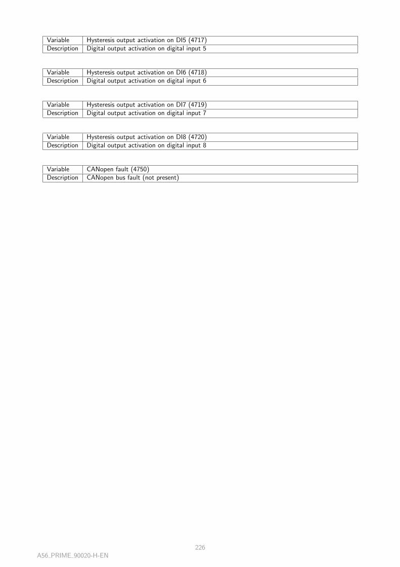
Variable Hysteresis output activation on DI5 (4717)Description Digital output activation on digital input 5
Variable Hysteresis output activation on DI6 (4718)Description Digital output activation on digital input 6
Variable Hysteresis output activation on DI7 (4719)Description Digital output activation on digital input 7
Variable Hysteresis output activation on DI8 (4720)Description Digital output activation on digital input 8
Variable CANopen fault (4750)Description CANopen bus fault (not present)
A56 PRIME 90020-H-EN226
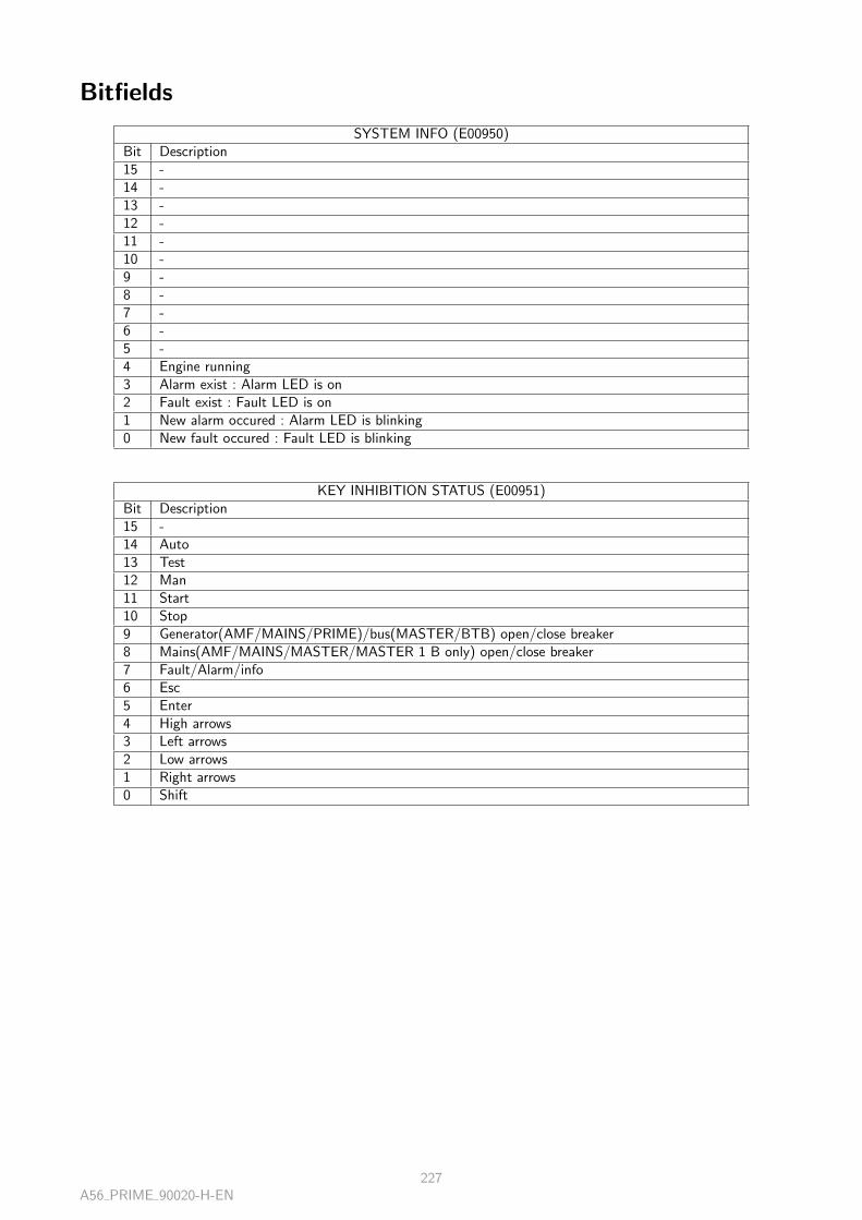
Bitfields
SYSTEM INFO (E00950)Bit Description15 -14 -13 -12 -11 -10 -9 -8 -7 -6 -5 -4 Engine running3 Alarm exist : Alarm LED is on2 Fault exist : Fault LED is on1 New alarm occured : Alarm LED is blinking0 New fault occured : Fault LED is blinking
KEY INHIBITION STATUS (E00951)Bit Description15 -14 Auto13 Test12 Man11 Start10 Stop9 Generator(AMF/MAINS/PRIME)/bus(MASTER/BTB) open/close breaker8 Mains(AMF/MAINS/MASTER/MASTER 1 B only) open/close breaker7 Fault/Alarm/info6 Esc5 Enter4 High arrows3 Left arrows2 Low arrows1 Right arrows0 Shift
A56 PRIME 90020-H-EN227

LED STATUS (E00952)Bit Description15 -14 -13 -12 -11 -10 -9 -8 Generator (AMF/MAINS/PRIME/SYNCHRO) /bus (MASTER/MASTER 1B) voltage7 Alarm6 Generator (AMF/PRIME/MAINS) /bus (BTB/MASTER) breaker5 TEST4 Mains breaker (AMF/MAINS/MASTER/MASTER 1B only)3 MAN2 AUTO1 Bus voltage (SYNCHRO/PRIME/BTB) / Mains voltage (AMF/MAINS/MASTER/MASTER
1B)0 Fault
Digital input raw (E00953)Bit Description15 -14 -13 -12 -11 Analog 3 setup as digital input10 Analog 2 setup as digital input9 Analog 1 setup as digital input8 Digital input 9 on hardware7 Digital input 8 on hardware6 Digital input 7 on hardware5 Digital input 6 on hardware4 Digital input 5 on hardware3 Digital input 4 on hardware2 Digital input 3 on hardware1 Digital input 2 on hardware0 Digital input 1 on hardware
E00954 (Processed)Bit Description15 -14 -13 -12 -11 Analog input 3 setup as digital input10 Analog input 2 setup as digital input9 Analog input 1 setup as digital input8 Digital input 97 Digital input 86 Digital input 75 Digital input 64 Digital input 53 Digital input 42 Digital input 31 Digital input 20 Digital input 1
A56 PRIME 90020-H-EN228

E00955 (Processed)Bit Description15 CANopen digital Input 1614 CANopen digital Input 1513 CANopen digital Input 1412 CANopen digital Input 1311 CANopen digital Input 1210 CANopen digital Input 119 CANopen digital Input 108 CANopen digital Input 97 CANopen digital Input 86 CANopen digital Input 75 CANopen digital Input 64 CANopen digital Input 53 CANopen digital Input 42 CANopen digital Input 31 CANopen digital Input 20 CANopen digital Input 1
E00956 (Processed)Bit Description15 CANopen digital Input 3214 CANopen digital Input 3113 CANopen digital Input 3012 CANopen digital Input 2911 CANopen digital Input 2810 CANopen digital Input 279 CANopen digital Input 268 CANopen digital Input 257 CANopen digital Input 246 CANopen digital Input 235 CANopen digital Input 224 CANopen digital Input 213 CANopen digital Input 202 CANopen digital Input 191 CANopen digital Input 180 CANopen digital Input 17
E00957 (Processed)Bit Description15 -14 -13 -12 -11 -10 -9 -8 -7 Relay 26 Relay 15 Digital output 64 Digital output 53 Digital output 42 Digital output 31 Digital output 20 Digital output 1
A56 PRIME 90020-H-EN229

E00958 (Processed)Bit Description15 CANopen digital Output 1614 CANopen digital Output 1513 CANopen digital Output 1412 CANopen digital Output 1311 CANopen digital Output 1210 CANopen digital Output 119 CANopen digital Output 108 CANopen digital Output 97 CANopen digital Output 86 CANopen digital Output 75 CANopen digital Output 64 CANopen digital Output 53 CANopen digital Output 42 CANopen digital Output 31 CANopen digital Output 20 CANopen digital Output 1
E00959 (Processed)Bit Description15 CANopen digital Output 3214 CANopen digital Output 3113 CANopen digital Output 3012 CANopen digital Output 2911 CANopen digital Output 2810 CANopen digital Output 279 CANopen digital Output 268 CANopen digital Output 257 CANopen digital Output 246 CANopen digital Output 235 CANopen digital Output 224 CANopen digital Output 213 CANopen digital Output 202 CANopen digital Output 191 CANopen digital Output 180 CANopen digital Output 17
RESET MAINTENANCE & METERS (E10400)Bit Description15 Meters : Generator total kWh14 Meters : Generator total kVARh13 Meters : Mains total kWh12 Meters : Mains total kVARh11 Meters : Engine running hours10 Meters : Number of attempts to start9 Maintenance cycle 5 in days8 Maintenance cycle 4 in days7 Maintenance cycle 3 in days6 Maintenance cycle 2 in days5 Maintenance cycle 1 in days4 Maintenance cycle 5 in hours3 Maintenance cycle 4 in hours2 Maintenance cycle 3 in hours1 Maintenance cycle 2 in hours0 Maintenance cycle 1 in hours
A56 PRIME 90020-H-EN230
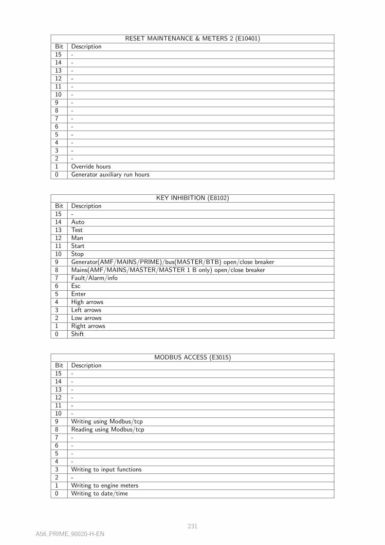
RESET MAINTENANCE & METERS 2 (E10401)Bit Description15 -14 -13 -12 -11 -10 -9 -8 -7 -6 -5 -4 -3 -2 -1 Override hours0 Generator auxiliary run hours
KEY INHIBITION (E8102)Bit Description15 -14 Auto13 Test12 Man11 Start10 Stop9 Generator(AMF/MAINS/PRIME)/bus(MASTER/BTB) open/close breaker8 Mains(AMF/MAINS/MASTER/MASTER 1 B only) open/close breaker7 Fault/Alarm/info6 Esc5 Enter4 High arrows3 Left arrows2 Low arrows1 Right arrows0 Shift
MODBUS ACCESS (E3015)Bit Description15 -14 -13 -12 -11 -10 -9 Writing using Modbus/tcp8 Reading using Modbus/tcp7 -6 -5 -4 -3 Writing to input functions2 -1 Writing to engine meters0 Writing to date/time
A56 PRIME 90020-H-EN231

E00960 (Alarm)Bit Var Description15 4171 Bus breaker close suddently14 4159 Bus breaker open suddently13 4158 Fail to open bus breaker12 4157 Fail to close bus breaker11 4205 Engine maximum water temperature level 210 4205 Engine maximum water temperature level 19 4204 Engine minimum oil pressure level 28 4204 Engine minimum oil pressure level 17 4203 Engine battery max volt level 26 4203 Engine battery max volt level 15 4202 Engine battery min volt level 24 4202 Engine battery min volt level 13 4201 Engine under speed level 22 4201 Engine under speed level11 4200 Engine overspeed level20 4200 Engine overspeed level1
E00961 (Fault)Bit Var Description15 4171 Bus breaker close suddently14 4159 Bus breaker open suddently13 4158 Fail to open bus breaker12 4157 Fail to close bus breaker11 4205 Engine maximum water temperature level 210 4205 Engine maximum water temperature level 19 4204 Engine minimum oil pressure level 28 4204 Engine minimum oil pressure level 17 4203 Engine battery max volt level 26 4203 Engine battery max volt level 15 4202 Engine battery min volt level 24 4202 Engine battery min volt level 13 4201 Engine under speed level 22 4201 Engine under speed level11 4200 Engine overspeed level20 4200 Engine overspeed level1
E00962 (Alarm)Bit Var Description15 4257 Generator/Power plant minimum kVAR level214 4257 Generator/Power plant minimum kVAR level113 4256 Generator/Power plant reverse kW level212 4256 Generator/Power plant reverse kW level111 4255 Generator/Power plant maximum kW level210 4255 Generator/Power plant maximum kW level19 4254 Generator/Power plant minimum kW level28 4254 Generator/Power plant minimum kW level17 4253 Generator/Power plant under voltage level26 4253 Generator/Power plant under voltage level15 4252 Generator/Power plant over voltage level24 4252 Generator/Power plant over voltage level13 4251 Generator/Power plant under frequency level 22 4251 Generator/Power plant under frequency level11 4250 Generator/Power plant over frequency level20 4250 Generator/Power plant over frequency level1
A56 PRIME 90020-H-EN232

E00963 (Fault)Bit Var Description15 4257 Generator/Power plant minimum kVAR level214 4257 Generator/Power plant minimum kVAR level113 4256 Generator/Power plant reverse kW level212 4256 Generator/Power plant reverse kW level111 4255 Generator/Power plant maximum kW level210 4255 Generator/Power plant maximum kW level19 4254 Generator/Power plant minimum kW level28 4254 Generator/Power plant minimum kW level17 4253 Generator/Power plant under voltage level26 4253 Generator/Power plant under voltage level15 4252 Generator/Power plant over voltage level24 4252 Generator/Power plant over voltage level13 4251 Generator/Power plant under frequency level 22 4251 Generator/Power plant under frequency level11 4250 Generator/Power plant over frequency level20 4250 Generator/Power plant over frequency level1
E00964 (Alarm)Bit Var Description15 4267 Earth fault level 214 4267 Earth fault level 113 4112 Last trip out12 4266 Uneven voltage11 4265 Uneven speed10 4264 Uneven kVAR9 4263 Uneven kW8 4262 Generator overcurrent7 4261 Generator maximum neutral current level26 4261 Generator maximum neutral current level15 4260 Generator maximum current level24 4260 Generator maximum current level13 4259 Generator/Power plant reverse kVAR level22 4259 Generator/Power plant reverse kVAR level11 4258 Generator/Power plant maximum kVAR level20 4258 Generator/Power plant maximum kVAR level1
E00965 (Fault)Bit Var Description15 4267 Earth fault level 214 4267 Earth fault level 113 4112 Last trip out12 4266 Uneven voltage11 4265 Uneven speed10 4264 Uneven kVAR9 4263 Uneven kW8 4262 Generator overcurrent7 4261 Generator maximum neutral current level26 4261 Generator maximum neutral current level15 4260 Generator maximum current level24 4260 Generator maximum current level13 4259 Generator/Power plant reverse kVAR level22 4259 Generator/Power plant reverse kVAR level11 4258 Generator/Power plant maximum kVAR level20 4258 Generator/Power plant maximum kVAR level1
A56 PRIME 90020-H-EN233

E00966 (Alarm)Bit Var Description15 4307 Bus/Mains minimum kVAR level214 4307 Bus/Mains minimum kVAR level113 4306 Bus/Mains reverse kW level212 4306 Bus/Mains reverse kW level111 4305 Bus/Mains maximum kW level210 4305 Bus/Mains maximum kW level19 4304 Bus/Mains minimum kW level28 4304 Bus/Mains minimum kW level17 4303 Bus/Mains under voltage level26 4303 Bus/Mains under voltage level15 4302 Bus/Mains over voltage level24 4302 Bus/Mains over voltage level13 4301 Bus/Mains under frequency level 22 4301 Bus/Mains under frequency level11 4300 Bus/Mains over frequency level20 4300 Bus/Mains over frequency level1
E00967 (Fault)Bit Var Description15 4307 Bus/Mains minimum kVAR level214 4307 Bus/Mains minimum kVAR level113 4306 Bus/Mains reverse kW level212 4306 Bus/Mains reverse kW level111 4305 Bus/Mains maximum kW level210 4305 Bus/Mains maximum kW level19 4304 Bus/Mains minimum kW level28 4304 Bus/Mains minimum kW level17 4303 Bus/Mains under voltage level26 4303 Bus/Mains under voltage level15 4302 Bus/Mains over voltage level24 4302 Bus/Mains over voltage level13 4301 Bus/Mains under frequency level 22 4301 Bus/Mains under frequency level11 4300 Bus/Mains over frequency level20 4300 Bus/Mains over frequency level1
E00968 (Alarm)Bit Var Description15 661 J1939 : DM1 malfunction14 660 J1939 : DM1 red13 659 J1939 : DM1 amber12 658 J1939 : DM1 protect11 657 J1939 : High overspeed10 656 J1939 : Overspeed9 655 J1939 : Very low oil pressure8 654 J1939 : Low oil pressure7 653 J1939 : Very high coolant temeprature6 652 J1939 : High coolant temeprature5 4311 Df/dt (Rocof)4 4310 Vector jump3 4309 Bus/Mains reverse kVAR level22 4309 Bus/Mains reverse kVAR level11 4308 Bus/Mains maximum kVAR level20 4308 Bus/Mains maximum kVAR level1
A56 PRIME 90020-H-EN234

E00969 (Fault)Bit Var Description15 661 J1939 : DM1 malfunction14 660 J1939 : DM1 red13 659 J1939 : DM1 amber12 658 J1939 : DM1 protect11 657 J1939 : High overspeed10 656 J1939 : Overspeed9 655 J1939 : Very low oil pressure8 654 J1939 : Low oil pressure7 653 J1939 : Very high coolant temeprature6 652 J1939 : High coolant temeprature5 4311 Df/dt (Rocof)4 4310 Vector jump3 4309 Bus/Mains reverse kVAR level22 4309 Bus/Mains reverse kVAR level11 4308 Bus/Mains maximum kVAR level20 4308 Bus/Mains maximum kVAR level1
E00970 (Alarm)Bit Var Description15 4478 Fail to stabilize voltage14 4477 Fail to stabilize speed13 4170 Generator breaker close suddently12 4156 Generator breaker open suddently11 4155 Fail to open generator breaker10 4154 Fail to close generator breaker9 4208 Minimum/maximum analog measure 3 (level2)8 4208 Minimum/maximum analog measure 3 (level1)7 4207 Minimum/maximum analog measure 2 (level2)6 4207 Minimum/maximum analog measure 2 (level1)5 4206 Minimum/maximum analog measure 1 (level2)4 4206 Minimum/maximum analog measure 1 (level1)3 - -2 600 CAN1 isolated product1 77 Phase mesure discordance0 4051 Fail to synchronize
E00971 (Fault)Bit Var Description15 - -14 - -13 4170 Generator breaker close suddently12 4156 Generator breaker open suddently11 4155 Fail to open generator breaker10 4154 Fail to close generator breaker9 4208 Minimum/maximum analog measure 3 (level2)8 4208 Minimum/maximum analog measure 3 (level1)7 4207 Minimum/maximum analog measure 2 (level2)6 4207 Minimum/maximum analog measure 2 (level1)5 4206 Minimum/maximum analog measure 1 (level2)4 4206 Minimum/maximum analog measure 1 (level1)3 - -2 600 CAN1 isolated product1 77 Phase mesure discordance0 4051 Fail to synchronize
A56 PRIME 90020-H-EN235

E00972 (Alarm)Bit Var Description15 - -14 859 Maintenance days n°513 858 Maintenance days n°412 857 Maintenance days n°311 856 Maintenance days n°210 855 Maintenance days n°19 854 Maintenance hours n°58 853 Maintenance hours n°47 852 Maintenance hours n°36 851 Maintenance hours n°25 850 Maintenance hours n°14 19 Overload microcontroler3 4108 Trip alarm (non essential load )2 4153 Breaker alarm1 650 J1939 alarm0 4750 CANopen alarm
E00973 (Fault)Bit Var Description15 - -14 - -13 - -12 - -11 - -10 - -9 650 J1939 fault8 4750 CANopen fault7 4152 Breaker fault6 4451 Sensor lost5 4475 Fail to start4 4473 Generator not ready3 4472 Fail to stop2 4505 Emergency stop1 4504 Coolant temperature fault0 4503 Oil pressure fault
E00974 (Alarm)Bit Var Description15 607 CAN1 mismatch protocole version14 CAN1 not enough GE13 605 CAN1 missing product12 4212 Maximum AVR output11 4211 Minimum AVR output10 4210 Maximum speed output9 4209 Minimum speed output8 4213 Overflow in equation7 4314 Mains voltage unbalance (level2)6 4314 Mains voltage unbalance (level1)5 4269 Generator current unbalance (level2)4 4269 Generator current unbalance (level1)3 4268 Generator/bus voltage unbalance (level2)2 4268 Generator/bus voltage unbalance (level1)1 4316 Bus measure error0 608 CAN1 missing MASTER
A56 PRIME 90020-H-EN236

E00975 (Fault)Bit Var Description15 - -14 606 CAN1 unknown product13 605 CAN1 missing product12 4212 Maximum AVR output11 4211 Minimum AVR output10 4210 Maximum speed output9 4209 Minimum speed output8 - -7 4314 Mains voltage unbalance (level2)6 4314 Mains voltage unbalance (level1)5 4269 Generator current unbalance (level2)4 4269 Generator current unbalance (level1)3 4268 Generator/bus voltage unbalance (level2)2 4268 Generator/bus voltage unbalance (level1)1 - -0 608 CAN1 missing MASTER
A56 PRIME 90020-H-EN237

1 / 3
CRE TechnologyBased in Sophia Antipolis, CRE TECHNOLOGY is a French manufacturer, ISO 9001 certified, employs nearly 25employees, all experts in their field. CRE TECHNOLOGY offers electronic products and electrical solutions dedicated to the control and the protection ofindustrial and marine generators: battery chargers, Generator sets controllers and synchronizing and parallelingequipments.
We are known for our skills, expertise and value-added solutions but also highly appreciated for our pre/after salesservices. CRE TECHNOLOGY's product development is focused on innovation.The key to our strategy is the availability of our products with a large stock capacity. Our company is highly recognized for technical achievements with over 1500 paralleling solutions sold each year, 35years of experience, and partners in 27 countries. 10% of our annual turnover is reinvested in R&D and we offer 7 new products per year and have the bestflexibility/price ratio on the market.
The next few years will see the expansion of our distribution network and our innovative product portfolio.
A worldwide distribution network
Consult the complete list of our worldwide distributors on our website https://www.cretechnology.com/en/cre-distributors.
TECHNICAL DOCUMENTATION
2 / 3
The company at a glance
1983CRE TECHNOLOGY is born. At the time, the company is a custom-product manufacturer. We enlarge our productrange and services to high standard technical units, particularly in the paralleling sector. Today with 35 years ofexperience, this custom expertise and our passion for technical challenges are still the company's best assets.
2002
GENSYS is launched. It will becomeCRE TECHNOLOGY ʼs best-seller and the basis of its notoriety.
Today, CRE TECHNOLOGY provides 3000 paralleling solutions each year. Most of them are ordered directly by
OEMs which appreciate our technical efficiency.
2006
CRE TECHNOLOGY, a member of the DSF Engineering and Distribution Generator, becomes independent from DSF
Technologies. The company realizes its ambitions: to develop new ranges and expand its distribution network. CRE
TECHNOLOGY now provides an extensive range of products in the genset control and paralleling market. Its
worldwide network grows continuously, covering lots of new countries every year. CRE TECHNOLOGY now provides
an extensive range of products in the genset control and paralleling market.
2009
CRE TECHNOLOGY is ISO 9001 certified with the 2008 version. DNV certification is added to the other GENSYS
MARINE approvals: Lloyds and BV.
2010CRE TECHNOLOGY diversifies its ranges of products by introducing a wide range of battery chargers within itsrange.
2012CRE TECHNOLOGY keeps developing new products in accordance with the market. The paralleling range nowincludes the GENSYS 2.0 core and the RDM 2.0, as well as the marine range with the GENSYS 2.0 MARINE (DNVapproved).
2015The new GENSYS COMPACT is in the range, and fully available for success, Lloyds Register marine approvals onGENSYS2.0 marine, with the exisiting DNV-GL marine approval.
2017The new UNIGEN 2.0 has been added to the range, to extend our offer on parallel and solutions. The global range isconstantly improved with a new PLC Solutions in order to customize even more our outcomes. A new AVRCOMPACT is being added to our catalog to extend our capabilities.
TOMORROW
New products, new members in the distribution network, and new exciting projects to build and win with you!

TECHNICAL DOCUMENTATION
3 / 3
CONTACTS
Postal address:130 allée Charles-Victor NaudinZone des TempliersSophia-Antipolis06410 BIOTFRANCE
Phone: +33 (0)4 92 38 86 82Fax: +33 (0)4 92 38 86 83Web site: http://www.cretechnology.comEmail: [email protected]
Technical support:
Phone: +33 (0)4 92 38 86 86 (8H30 – 12H00 / 14H00 – 18H00 GMT +1)Email: [email protected]: support-cretechnology.com (Spoken only)
Follow us on:


