Page 1
1 / 20 V.03-03-2013
THREE PHASE ELECTRONIC WATT-HOUR METER – VSE3T
TECHNICAL DOCUMENTS
Apply for three phase electronic watt-hour meter – VSE3T
o 230/400V - 5(6)A
o 230/400V - 50(100)A
o (100-120) V/(173-208)V - 5(6)A
Page 2
2 / 20 V.03-03-2013
CONTENT
I. Product introduction: .................................................................................................................... 3
1. Overview: ...................................................................................................................................... 3
2. Specification and technical parameters: ........................................................................................ 3
3. Characteristic curve: ...................................................................................................................... 3
4. Work principle: .............................................................................................................................. 4
5. Security: ........................................................................................................................................ 5
II. Description and installation:........................................................................................................ 6
1. Description: ................................................................................................................................... 6
2. The contents of LCD display: ....................................................................................................... 6
3. Meter installing and wiring. .......................................................................................................... 8
III. Function ...................................................................................................................................... 9
1. Measurement ............................................................................................................................... 11
2. Freeze .......................................................................................................................................... 11
3. Max Demand ............................................................................................................................... 11
4. Tariff ............................................................................................................................................ 11
5. Load curve .................................................................................................................................. 12
6. Remote data reading ................................................................................................................... 12
7. Battery ......................................................................................................................................... 12
IV. Phần mềm ................................................................................................................................. 13
1. Log in .......................................................................................................................................... 13
2. Configuration ............................................................................................................................. 13
3. Manager user .............................................................................................................................. 13
4. Read Operate .............................................................................................................................. 13
5. Write Operate ............................................................................................................................. 15
V. Transportation and storage ........................................................................................................ 19
VI. After sales service .................................................................................................................... 19
Page 3
3 / 20 V.03-03-2013
I. Product introduction:
1. Overview:
The three phase electronic watt-hour meter (VSE3T) is a product of VINASINO Electrical
Equipment Joint Stock Company, produced on modern process lines, used measurement IC with high
accuracy. The features are compatible with customer demands and comply with standards: IEC
62052-11, IEC 62053-21; IEC 62053-22 and IEC 62053-23.
VSE3T can integrate remote reading function by adding PLC module or GPRS module, using or
not using module does not affect the measurement features of meter. This is very convenient for
development after, switching power recording mode flexibly as well as save cost.
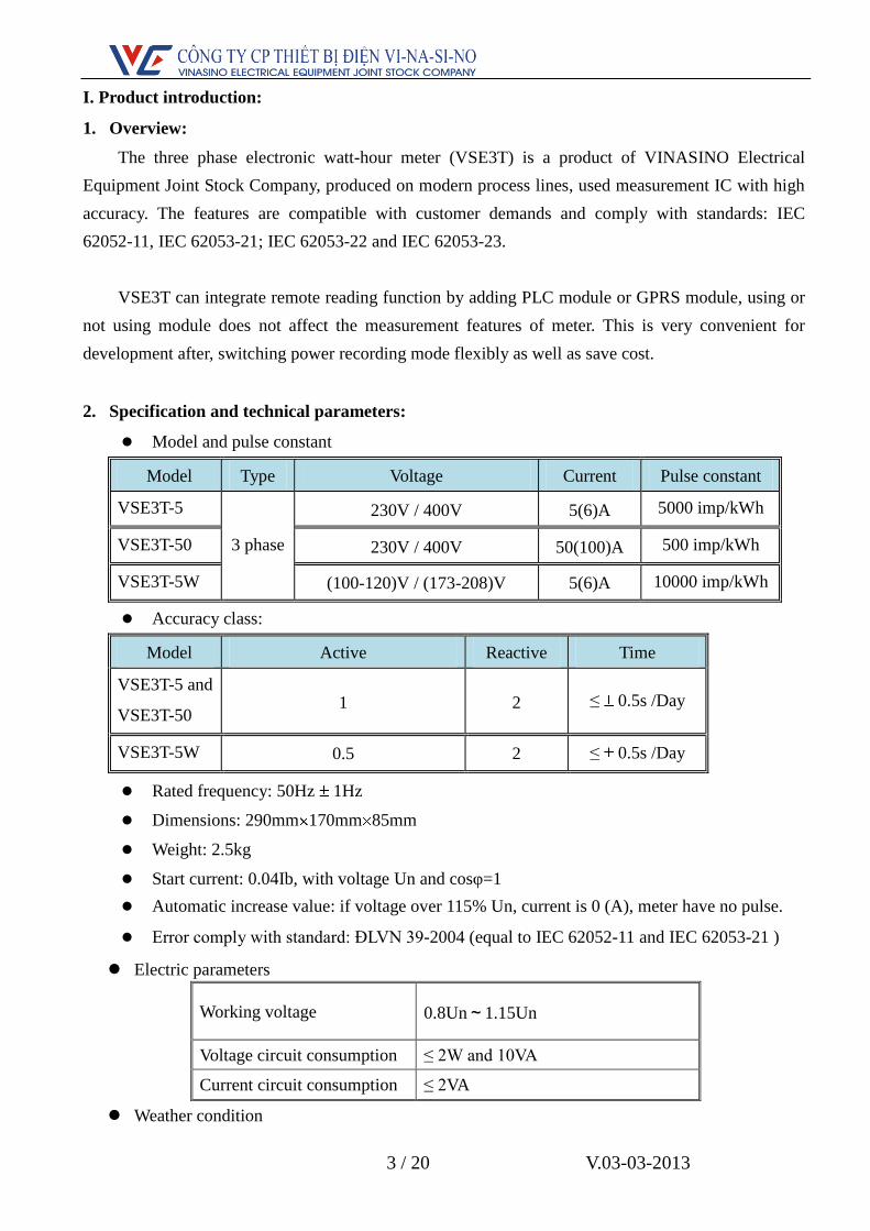
2. Specification and technical parameters:
Model and pulse constant
Model Type Voltage Current Pulse constant
VSE3T-5
3 phase
230V / 400V 5(6)A 5000 imp/kWh
VSE3T-50 230V / 400V 50(100)A 500 imp/kWh
VSE3T-5W (100-120)V / (173-208)V 5(6)A 10000 imp/kWh
Accuracy class:
Model Active Reactive Time
VSE3T-5 and
VSE3T-50 1 2 ≤ 0.5s /Day
VSE3T-5W 0.5 2 ≤ 0.5s /Day
Rated frequency: 50Hz 1Hz
Dimensions: 290mm 170mm 85mm
Weight: 2.5kg
Start current: 0.04Ib, with voltage Un and cosφ=1
Automatic increase value: if voltage over 115% Un, current is 0 (A), meter have no pulse.
Error comply with standard: ĐLVN 39-2004 (equal to IEC 62052-11 and IEC 62053-21 )
Electric parameters
Working voltage 0.8Un~1.15Un
Voltage circuit consumption ≤ 2W and 10VA
Current circuit consumption ≤ 2VA
Weather condition
Page 4
4 / 20 V.03-03-2013
Normal working temperature 0℃~+50℃
Extremeworking temperature -10℃~+70℃
Storage and transport temperature 0℃~+85℃
Storage and working humidity <95%
Technical parameters:
3. Characteristic curve:
3.1. Error curve (kWh)
3.2. Error curve (kvarh)
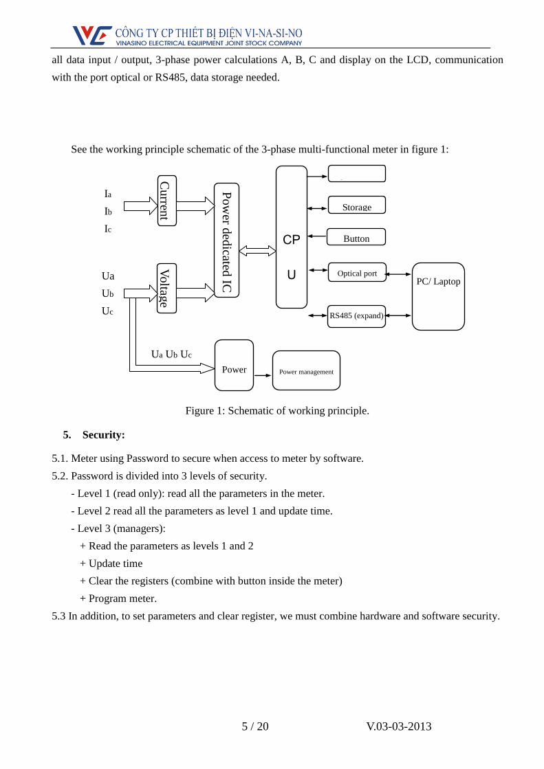
4. Work principle:
When the meter is working voltages and currents are sampled separately. The data is processed by
a special integrated circuit to calculation power and then sent to the CPU for processing. CPU handles
Display LCD
Communication port RS485,photoelectricity
Communication baud rate 300bps
Communication protocol IEC 62056-21
Page 5
5 / 20 V.03-03-2013
all data input / output, 3-phase power calculations A, B, C and display on the LCD, communication
with the port optical or RS485, data storage needed.
See the working principle schematic of the 3-phase multi-functional meter in figure 1:
Figure 1: Schematic of working principle.
5. Security:
5.1. Meter using Password to secure when access to meter by software.
5.2. Password is divided into 3 levels of security.
- Level 1 (read only): read all the parameters in the meter.
- Level 2 read all the parameters as level 1 and update time.
- Level 3 (managers):
+ Read the parameters as levels 1 and 2
+ Update time
+ Clear the registers (combine with button inside the meter)
+ Program meter.
5.3 In addition, to set parameters and clear register, we must combine hardware and software security.
Cu
rrent
V
oltag
e
Pow
er ded
icated IC
CP
U
LCD
Storage
Power
Ia
Ib
Ic
Ua
Ub
Uc
Ua Ub Uc
Button
Power management
PC/ Laptop
Optical port
RS485 (expand)
Page 6
6 / 20 V.03-03-2013
II. Description and installation:
1. Description:
Hình 2: Outline description of electric meter VSE3T.
2. The contents of LCD display:
Pulse light kvarh
Pulse light kWh
Optical port
Function button
LCD
Module position
Billing Reset button
Page 7
7 / 20 V.03-03-2013
2.1. After supplied power, meter will start in 3 seconds (LCD display full content), after that, meter
display the parameters in the automatic mode (these parameters can be set ). Time interval between the
parameters displayed can be programmed from 1 second to 60 seconds.
2.2. The parameter display scrolls automatically install the manufacturer's default
- Screen 1: day: month: year (real time)
- Screen 2: Time minute seconds (Realtime)
- Screen 3: ID meter
- Screen 4: The total active energy
- Screen 5: Tariff 1 active energy
- Screen 6: Tariff 2 active energy
- Screen 7: Tariff 3 active energy
- Screen 8: The total reactive energy
- Screen 9: Value Max Demand
- Screen 10: Time minute seconds occurred Max Demand
- Screen 11: day: month: year occurred Max Demand
2.3. Can view parameters by pressing the Menu button.
2.4. When power cut, the screen automatically turns off and reappears when pressing the Menu button
or when power on.
2.5. Press and hold Menu button for 3 seconds to enter the sub menu inside. Press and hold button for
3 seconds when the LCD screen display "E" to return to the previous menu.
2.6. When power on if not press the button for 10 seconds, the screen will change to automatic mode.
2.7. Sub menu:
- Menu 1: electric parameters .
+ Voltage of each phase
+ Current of each phase
+ Frequency
+ Phase angle
+ Cosφ
- Menu 2: power:
+ Active power of each phase
+ Total active power
+ Reactive power of each phase.
+ Total active power.
- Menu 3: Max Demand history: store Max Demand history, include Max Demand value and
Page 8
8 / 20 V.03-03-2013
time.
- Menu 4: Billing reset history (store value from 12 months).
+ Active energy of each tariff
+ Total active energy
+ Reactive energy of each tariff
+ Total reactive energy
+ Settlement time
- Menu 5: Number of programming and time of last 4 times programming
- Menu 6: Number of power cut and time of last 10 power cut times (include time of power on).
- Menu 7: CT-PT ratio.
Symbol description on LCD
Symbol Description
Display: V; A; kW; kWh; kVAr; kVArh
It flashes when the battery lacks of power.
It is displayed when the meter is programmable.
It is displayed when the transmission via IR, RF and RS485.
It shows when the meter is locked (can’t reset); it disappears when the reset is
allowed.
Ua Ub Uc
Voltage notice: displays the symbols of the powered items; don’t display the
symbols of the unpowered items.
Ua Ub Uc flashes when the phases are wrong phase sequence.
Ia Ib Ic Current notice: disply the symbols of the current phases; don’t display the
symbols of the 0 current phases. If any phase has reverse current, its symbol
flashes.
The digit following letter “R” display current tariff.
Freq Frequency
Prog Number of programming: only count when config meter, change password, reset
register.
P.Cut Times of power cut.
R
Page 9
9 / 20 V.03-03-2013
2.8. Display error warning: when error occurs, LCD display error by code:
Err-07 Err-06 Err-05 Err-04 Err-03 Err-01
Overcurrent 3-phase
unbalanced
Over-voltage Phase
missing
Reverse
phase
order
Hardware
error
2.9. Pulse light: there are 2 pulse light used for checking error and calibration.
- kWh light: according to active power
- kVArh light: according to reactive power
Speed of lights blink pulses indicates the magnitude of the load
2.10. Photoelectricity port:
- Photoelectricity port allow reading all data and programming meter. In addition, we can read and
program meter by RS485 port.
- Photoelectricity port comply with IEC 62056-21 standard, can use photoelectricity reader to
connect to computer by RS232 or USB port.
Notice:
- Meter will not warn phase wrong if phase 1 or phase 2 fail
- CT-PT ratio was set up by software. If do not use CT-PT ratio is 1:1.
3. Meter installing and wiring:
3.1 Meter sealed lead after quality control. Need to check sealed lead before mounting. The meter
does not lead seals or too long storage time will be taken to the relevant department to check, the
quality meter can be mounted and used.
3.2 Meters are installed in a dry and ventilated place, be fixed by 1 hook and 2 screws (3 screws
M5x25 used). Under the bottom cover is fixed on a block flame retardant materials and shock to
ensure safe installation and use. Meters will be installed in protective cabinets in dusty or dirty areas
where damaging agents meters (Priority cabinets used in composite materials for safe use will degrade
RF radio or GPRS):
Page 10
10 / 20 V.03-03-2013
Hình 3: Dimensions and installing diagram of electric meter VSE3T.
3.3.Wiring diagram of meter terminal (see details in the wiring diagram at the reverse side of the
terminal cover)
Notice: For VSE3T-50 type, combine voltage bridge when wiring (not applied for VSE3T-5 type)
3.4. Schematic diagram of active test port:
Vcc
Vcc=5V
R=1(kΩ)
e pulse width 80ms
Connect to
standard meter
Page 11
11 / 20 V.03-03-2013
III. Function description :
1. Measurement:
1.1. Meter can measure these follow parameters:
- Total active power kWh.
- Active power of each tariff.
- Total reactive power kVArh (both uplink and downlink).
- Reactive power of each tariff.
- Current active power (kW).
- Current reactive power (kVAr)
- Total power factor cosφ, phase angle of each phase.
- Current (A) and voltage (V) 3 phase.
- Frequency (Hz).
1.2. Anti-power-theft: When the meter has illegal operations (reverse current, wrong wiring of
phase line and null line, ground line connects to load), it should be able to measure
normally.
1.3. Electric energy will be secured (can’t clear). Need to combine both button and software to
clear.
2. Freeze:
2.1. Monthly freeze: the freeze date can be set any day, freeze time at 0h00' of the installation
date.
2.2. Freeze content: total active power, power of 4 tariffs, total reactive power and sub-phase
reactive power.
2.3. Numbers of frozen section: 12 months at most.
2.4. In addition, freeze by pressing Billing reset button with programmable buttons allow the
meter: Press button allows programmers, the icon appears , press Billing reset button until
the the icon appears is success , this icon will appear to the end of the current cycle integrals,
in this period not allow the freeze manual.
3. Max Demand :
3.1 Max demand period: 1~60min. The value used to calculate the Max Demand is the average
power value during the period integrals
3.2. Save max demand value and time occurred max demand.
3.3. Monthly freeze, can save the max demand value of 12 months .
4. Tariff:
4.1 .Tariff registers: Meter have registers attach with each respective tariff
4.2. Tariff regime: Meter can be programmed from 1 to 4 tariffs: Rate 1, Rate 2, Rate 3,
Page 12
12 / 20 V.03-03-2013
Rate 4. Users can set the tariff period through software
4.3. Support 120 holiday tables, 12 season tables, 12 week tables and 6 daily time interval
tables (each has 16 time intervals ) at most.
5. Load curve:
5.1. Able to save load power to registers (active and reactive power registers) after each cycle
integrals. Can read load curve in the form of data tables or graphs.
5.2. Storage time: 180 days (1 channel with integral time is 30 minutes).
5.3. When the memory is full, new data will overwrite the old data.
6. Remote data reading:
6.1 Meter can integrate remote data reading modules: PLC module PLC or GPRS module.
6.2 Can use remote reading system of 1 phase meter VSE11.
6.3 Can read total power and power of each tariff.
6.4 Power consumption of PLC module: ≤ 2W.
6.5 Baud rate: 9600bps
6.6 Max distance: 1000m
7. Battery
7.1 Before meter used, battery will supply power and can store in 2 years. After meter used,
battery can use in 10 years.
7.2 Symbol on LCD will flash if battery capacity is low.
Page 13
13 / 20 V.03-03-2013
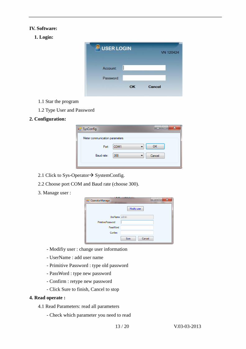
IV. Software:
1. Login:
1.1 Star the program
1.2 Type User and Password
2. Configuration:
2.1 Click to Sys-Operator SystemConfig.
2.2 Choose port COM and Baud rate (choose 300).
3. Manage user :
- Modifiy user : change user information
- UserName : add user name
- Primitive Password : type old password
- PassWord : type new password
- Confirm : retype new password
- Click Sure to finish, Cancel to stop
4. Read operate :
4.1 Read Parameters: read all parameters
- Check which parameter you need to read
Page 14
14 / 20 V.03-03-2013
- Click Read to read, enter meter password. “Excute finish! Receive data OK!”
announcement appears when read successfully.
- Reading result will be saved automatically with format: Read day_read time_meter ID
(Example: 01/03/2012 09:36:12_000012350068). This data can only read by software and can not
be edited. Click “Import” and choose saved data to view.
- Check which parameter you need to print (Check to print) and click Print. (You can click
Printpreview to view the format before printing).
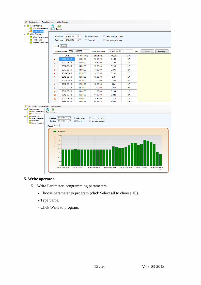
4.2 Load Profile:
- Choose time interval to read load curve (Start data: first day, End data: last day). Choose
“Read all” to read all position on load curve stored in meter.
- Choose channel of load profile:
+ Active power.
+ Lead reactive power.
+ Lag reactive power.
- Click “Read load curve” to read, enter meter password. “Excute finish! Receive data
OK!” announcement appears when read successfully.
- Click “Drawing” to draw the graph. Choose Report to view data as table or graph.
- Export to export file (excel).
Page 15
15 / 20 V.03-03-2013
5. Write operate :
5.1 Write Parameter: programming parameters
- Choose parameter to program (click Select all to choose all).
- Type value.
- Click Write to program.
Page 16
16 / 20 V.03-03-2013
Parameters setting:
- MD interval [min]: time for calculating Max demand. structure: TT (unit : minute).
- Billing date: day to freeze data (structure: dd), meter will freeze data at 0h00’ of that day.
- System switch: Unlock: able to clear register (in this mode, press enable interrupt button
and press AN5 button to clear register).
Lock: Unable to clear register.
- Phase fail threshold: warning phase fail (xxx.x% of Un). If voltage is lower than set up,
meter will warn phase
- Over voltage threshold: warning over voltage (xxx.x% of Un). If voltage is over than set
up, meter will warn over voltage.
- Over-current threshold: warning overcurent (xxx.x% of In). If current is over than set up,
meter will warn over current.
- Three-phase unbalance: warning 3 phase is unbalance (xxx.x% ofUn). If voltage of 3
phase is unequal, meter will warn.
- Decimal number: set up how many decimal place of electric power (0, 1 or 2 decimal
places).
- CT-PT ratio: Ratio of PT and CT
- Level1/2/3 meter password: set up password of meter (use only for user in level 3)
- RTC: set up real time belong to clock on computer (Meter time: time on meter; PC time:
Page 17
17 / 20 V.03-03-2013
time on computer).
- IP Address + Port: IP address and Port of network (use for module GPRS).
- APN: APN of mobile network (use for module GPRS).
- Configuration Load curve: reset load curve
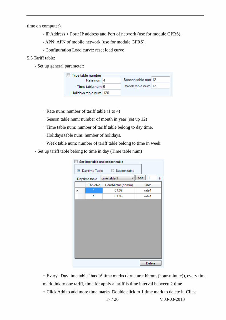
5.3 Tariff table:
- Set up general parameter:
+ Rate num: number of tariff table (1 to 4)
+ Season table num: number of month in year (set up 12)
+ Time table num: number of tariff table belong to day time.
+ Holidays table num: number of holidays.
+ Week table num: number of tariff table belong to time in week.
- Set up tariff table belong to time in day (Time table num)
+ Every “Day time table” has 16 time marks (structure: hhmm (hour-minute)), every time
mark link to one tariff, time for apply a tariff is time interval between 2 time
+ Click Add to add more time marks. Double click to 1 time mark to delete it. Click
Page 18
18 / 20 V.03-03-2013
“Delete” to delete entire table.
+ Click “Save”; “Write” to program meter.
- Set up Season table:
+ There are 12 months, structure: ddmm (day-month)
+ Click Add to add months. Double click to 1 time marks to delete it. Click “Delete” to
delete entire table
+ Click “Save”; “Write” to program meter
- Set up Week table:
+ Choose tariff table belong to time (time table), link to every day in week.
+ Click “Save”; “Write” to program meter.
5.4. Screen Show Set:
Page 19
19 / 20 V.03-03-2013
- Time interval between: time interval between 2 parameters displayed, structure: ss (second)
- Auto creen show set: choose parameters to display in auto mode.
- Manual creen show set: choose parameters to display in manual mode.
- Click “Write” to program.
V. Transportation and storage:
Our product is not demanding in the packaging and transportation, put the meter on a bearer for
storage, stack them and not to exceed six stacked layers.
Storage must be clean, the temperature of 00C ~ 85
0C; relative humidity not exceeding 95%,
with no harmful corrosive agents in the air.
VI. After sales service:
We have responsibility to repair or replace free of charge within 12 months from date of
mounting or 18 months after the date of distribution in terms of user compliance manuals and
sealed lead intact. We guarantee to provide after-sales service after 18 months.
Page 20
20 / 20 V.03-03-2013
VINASINO ELECTRIC EQUIPMENT JOINT STOCK COMPANY
Address: Lot H.08, Street No.1, Long Hau IP, Can Giuoc
District, Long An Province, Vietnam.
Tel: (84.8) 3873 4630/1/2/3/4
Fax: (84.8) 3873 4635