technical EC ref. : rev. : T 6055 GB 1 sheet Swing blocks for wire rope date : page : June 05 1/2 Applications The swing blocks of EC type are mainly used for temporary applications for lifting or pulling. They can be suspended to a fixed or mobile anchorage point with the right strength corresponding to the required load. Thanks to an easy instalment and a light weight, this is the most current block used for repairing operations. These swing blocks are most often used as winch accessory on 4WD cars. Description The large holes in the bearing flanges offer several anchorage alternatives means of shackles, axles, chains, hooks, slings. The holes can also be used as handles for an easy transportation. Once the swing blocks are attached, locking the two flanges, the opening is impossible making the pulling or lifting operation in full security. Technical characteristics Ultimate load 4 times the Working Load Limit (WLL). Zinc bichromated coating as finishing. The sheaves are fitted on tempered and cemented pins with a full covered lubricating nipple. Dimensional characteristics wi re rop e Ø outside Ø of the roller WLL* mini maxi E H K A B weight t mm mm mm mm mm mm mm kg type 1.6 8 9 100 180 60 66 40 2.2 EC1.6-100E9 3.2 10 12 160 260 80 86 50 4.8 EC3.2-160E12 5 13 15 200 330 100 106 60 9.3 EC5-200E15 8 16 18 250 410 120 138 80 19. 4 EC8-250E18 * Wor king Load Li mit Subjec ted to tec hnical m odifications without notice – Non c ontrac tual doc ument. H B A K www.tractelsolutions.com
Transcript
technical EC ref. : rev. :
T 6055 GB 1
sheet Swing blocks for wire rope
date : page :
June 05 1/2
Applications The swing blocks of EC type are mainly used for temporary applications for l ifting or pulling. They can be su spended to a fixed or mobile anchorage point with the right strength corresponding to the required load. Thanks to an easy instalment and a light weight, this is the most current block used for repairing operations. These swing blocks are most often used as winch accessory on 4WD cars. Description The large holes in the bearing flanges offer several anchorage alternatives means of shackles, axles, chains, hooks, slings. The holes can also be used as handles for an easy transportation. Once the swing blocks are attached, locking the two flanges, the opening is impossible making the pulling or l ifting operation in full security. Technical characteristics Ultimate load 4 times the Working Load Limit (WLL). Zinc bichromated coating as finishing. The sheaves are fitted on tempered and cemented pins with a full covered lubricating nipple.
Non-conform uses DO NOT USE FOR PERSONNEL LIFTING. Strictly forbidden to either be under or walk under the load. Do not use as a lifting block (holes profile not suitable). Never use the block without priory checking:
parts correctly assembled, excessive movement, excessive wearing or corrosion, deformation, no weld corrosion or cracking, free rotating sheave.
Prior to using the block, check for proper position and locking of the axles. Threaded axle head should be visible after applications of nuts.
Wire rope strength reduction The ratio between the pitch diameter of the sheave and the wire rope diameter, called the winding ratio, alters the tensile strength in the wire rope as hereafter:
Winding ratio Reduction
6 21% 8 17%
10 14% 15 11% 20 9%
Above values are given for information only, depending on the construction of the wire rope.
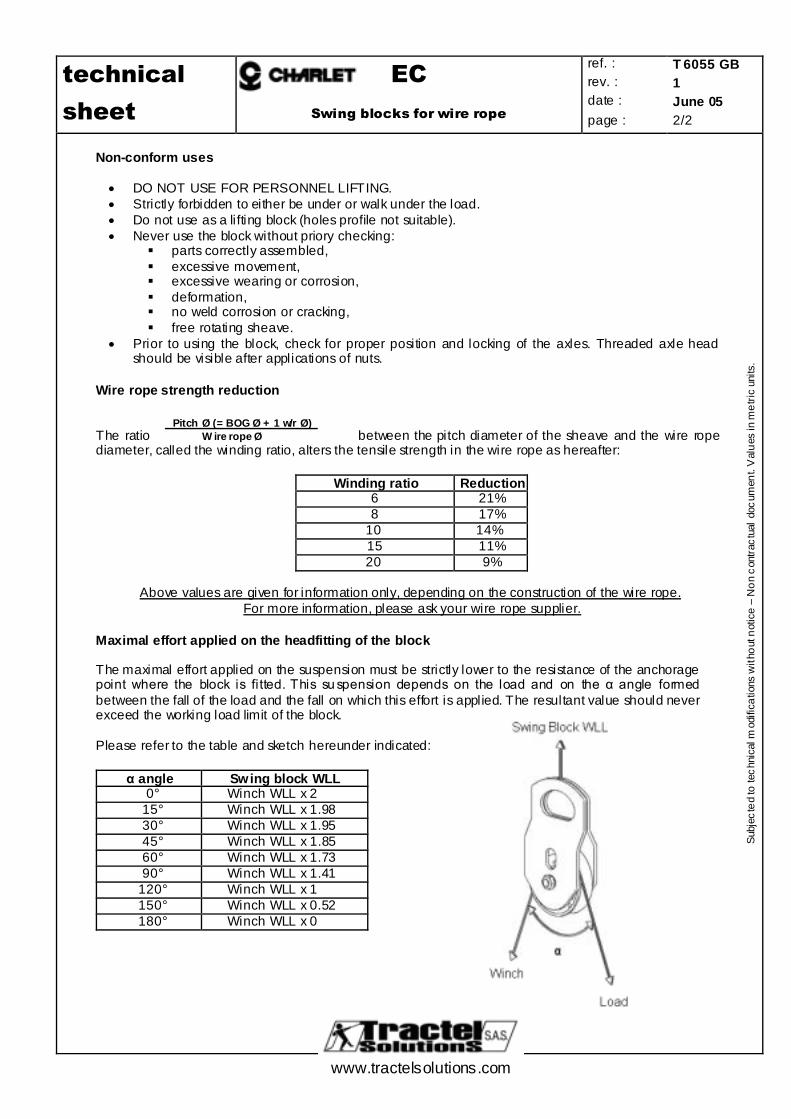
For more information, please ask your wire rope supplier. Maximal effort applied on the headfitting of the block The maximal effort applied on the suspension must be strictly lower to the resistance of the anchorage point where the block is fitted. This su spension depends on the load and on the α angle formed between the fall of the load and the fall on which this effort is applied. The resultant value should never exceed the working load limit of the block. Please refer to the table and sketch hereunder indicated:
α angle Swing block WLL 0° Winch WLL x 2
15° Winch WLL x 1.98 30° Winch WLL x 1.95 45° Winch WLL x 1.85 60° Winch WLL x 1.73 90° Winch WLL x 1.41
120° Winch WLL x 1 150° Winch WLL x 0.52 180° Winch WLL x 0
Sheet Snatch pulley with wire rope guide flangesdate :page :
June 131 / 2
Sheet 61
www.tractelsolutions.com
Sub
ject
edto
tech
nica
lmod
ifica
tion
with
outn
otic
e-N
onco
ntra
ctua
ldoc
umen
t.
Description
Side opening pulley
The flanges are designed to prevent wire rope slipping out of the groove when the liftingoperation begins.The pressed flanges are specially designed to resist against brutal shocks.
The pulleys are provided with a steel sheave with bronze bushing and a hook with safety latch
Sheet Snatch pulley with wire rope guide flangesdate :page :
June 132 / 2
Sheet 61
www.tractelsolutions.com
Sub
ject
edto
tech
nica
lmod
ifica
tion
with
outn
otic
e-N
onco
ntra
ctua
ldoc
umen
t.
Technical characteristicsUltimate load is 4 times the working load limit (WLL).Zinc bichromated coating.
Non-conform usesNEVER USE FOR PERSONNEL LIFTING.Always use suitable rope (size, length and capacity)Strictly forbidden to either be under or to walk under the load.The block should be regularly inspected (priory checking: parts correctly assembled, no excessive movement, noexcessive wearing or corrosion, no deformation, no weld corrosion or cracking, free rotating sheave).Prior to using the block, check for proper position and locking of the snatch block.Never use a block with a hook top anchor point without ensuring that the safety latch is correctly operated andfree from deformation.For lifting operations, the user must refer to the safety rules and regulations applicable to this application.The operator should never release the rope when a load is suspended or leave a suspended load unsupervised.Never install a Charlet return pulley as a hook block on lifting equipments (crane, hoist, ...).
Calculation of loading of a snatch blocksThe maximum Working Load Limit (WLL) written on the side of the block is the maximum load that should be exerted onthe block and its connecting fitting.This total load value F varies with the angle ( ) between the incoming and departing lines to the block. The followingtable indicates the factor to be multiplied by the line pull to obtain the total load F on the block.
Angle Load on the suspension(F)
0° Winch WLL x 215° Winch WLL x 1,9830° Winch WLL x 1,9545° Winch WLL x 1,8560° Winch WLL x 1,7390° Winch WLL x 1,41
120° Winch WLL x 1150° Winch WLL x 0,52180° Winch WLL x 0
Always ensure :F < pulley WLL
F < anchoring point resistance.
F
Load on the suspension
Winch Load
Sheet 62
technical EG ref. : rev. :2
T 6097 GB
sheet Light duty pulley for wire rope
date : page :
Feb 14 1/2
Description Light duty pulley for wire rope This pulley can be used as a return pulley with a wire rope and it is provided with a welded pressed steel sheave and a hook with safety catch. Can be used at low rotation speed only
Dimensional characteristics
*
* WLL : Work Load Limit Dimensions in mm ** bronze bush
• Ultimate load is 4 times the working load limit (WLL). • Zinc bichromated coating.
Non-conform uses
• NEVER USE FOR PERSONNEL LIFTING. • Always use suitable rope (size, length and capacity) • Strictly forbidden to either be under or to walk under the load. • The block should be regularly inspected (priory checking: parts correctly assembled, no
excessive movement, no excessive wearing or corrosion, no deformation, no weld corrosion or cracking, free rotating sheave).
• Prior to using the block, check for proper position and locking of the snatch block. • Never use a block with a hook as headfitting without ensuring that the safety latch is correctly
operated and free from deformation. • For lifting operations, the user must refer to the safety rules and regulations applicable to this
issue. • The operator is not authorised to release the rope or leave equipments out of control when a
load is hanged up on a pulley. • Never install a Charlet return pulley as a hook block on lifting equipments (crane, hoist, ...).
Calculation of loading of a snatch blocks
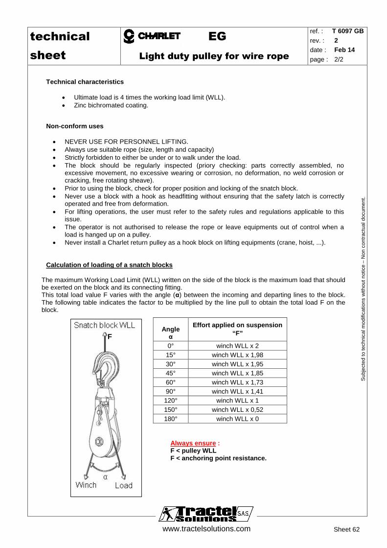
The maximum Working Load Limit (WLL) written on the side of the block is the maximum load that should be exerted on the block and its connecting fitting. This total load value F varies with the angle (α) between the incoming and departing lines to the block. The following table indicates the factor to be multiplied by the line pull to obtain the total load F on the block.
Always ensure : F < pulley WLL F < anchoring point resistance.
Angle α
Effort applied on suspension “F”
0° winch WLL x 2 15° winch WLL x 1,98 30° winch WLL x 1,95 45° winch WLL x 1,85 60° winch WLL x 1,73 90° winch WLL x 1,41
120° winch WLL x 1 150° winch WLL x 0,52 180° winch WLL x 0
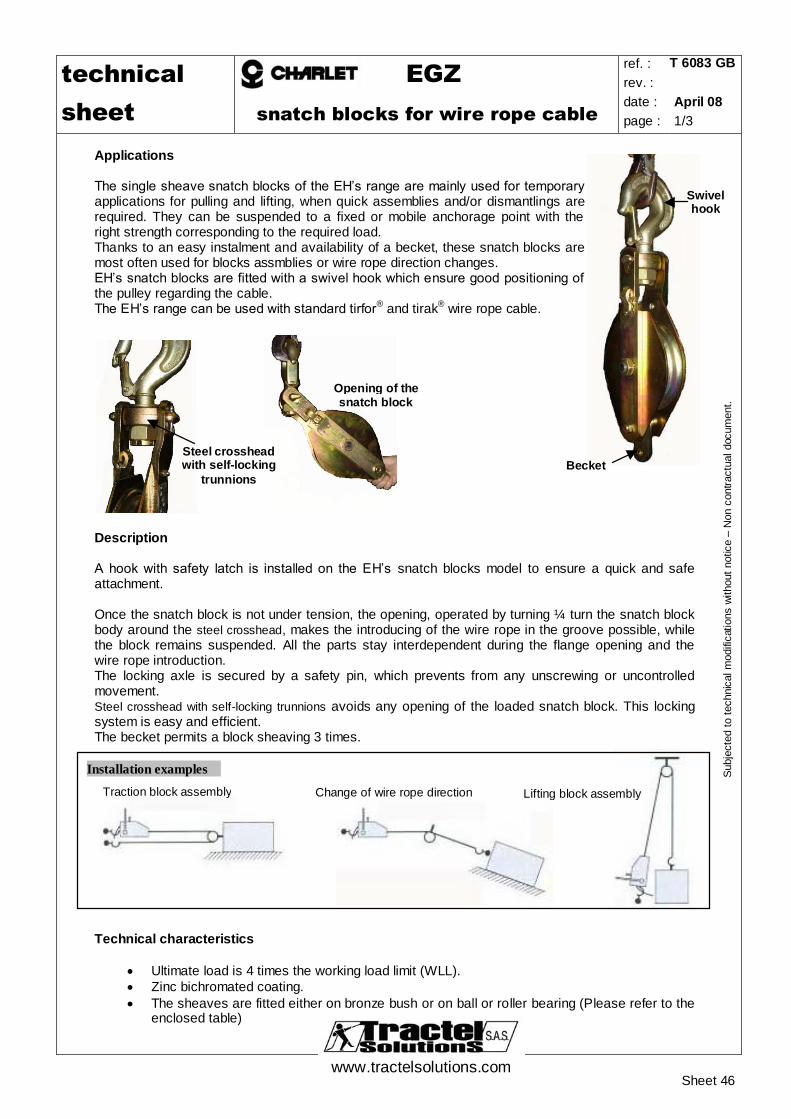
Applications The single sheave snatch blocks of the EH’s range are mainly used for temporary applications for pulling and lifting, when quick assemblies and/or dismantlings are required. They can be suspended to a fixed or mobile anchorage point with the right strength corresponding to the required load. Thanks to an easy instalment and availability of a becket, these snatch blocks are most often used for blocks assmblies or wire rope direction changes. EH’s snatch blocks are fitted with a swivel hook which ensure good positioning of the pulley regarding the cable. The EH’s range can be used with standard tirfor® and tirak® wire rope cable.
Description A hook with safety latch is installed on the EH’s snatch blocks model to ensure a quick and safe attachment.
Once the snatch block is not under tension, the opening, operated by turning ¼ turn the snatch block body around the steel crosshead, makes the introducing of the wire rope in the groove possible, while the block remains suspended. All the parts stay interdependent during the flange opening and the wire rope introduction. The locking axle is secured by a safety pin, which prevents from any unscrewing or uncontrolled movement. Steel crosshead with self-locking trunnions avoids any opening of the loaded snatch block. This locking system is easy and efficient. The becket permits a block sheaving 3 times.
Technical characteristics
Ultimate load is 4 times the working load limit (WLL). Zinc bichromated coating. The sheaves are fitted either on bronze bush or on ball or roller bearing (Please refer to the
enclosed table)
Steel crosshead with self-locking
trunnions
Opening of the snatch block
Traction block assembly Change of wire rope direction
NEVER USE FOR PERSONNEL LIFTING. Strictly forbidden to either be under or to walk under the load. The block should be regularly inspected (priory checking: parts correctly assembled, no
excessive movement, no excessive wearing or corrosion, no deformation, no weld corrosion or cracking, free rotating sheave).
Prior to using the block, check for proper position and locking of the snatch block. Never use a block with a hook as headfitting without ensuring that the safety latch is correctly
operated and free from deformation. For lifting operations, the user must refer to the safety rules and regulations applicable to this
issue. When using a block sheaving 3 times, ensure that the block on which the becket is loaded is
not over-loaded (see here after).
Wire rope strength reduction
The ratio between the pitch diameter of the sheave and the wire rope diameter, called the winding ratio, alters the tensile strength in the wire rope as hereafter:
Winding ratio Reduction
6 21% 8 17%
10 14% 15 11% 20 9%
Above values are given for information only, up to the construction of the wire rope.
For more information, please ask your wire rope supplier.
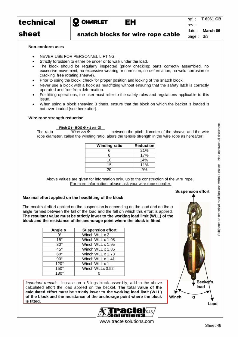
Maximal effort applied on the headfitting of the block
The maximal effort applied on the suspension is depending on the load and on the α angle formed between the fall of the load and the fall on which this effort is applied. The resultant value must be strictly lower to the working load limit (WLL) of the block and the resistance of the anchorage point where the block is fitted.
Angle α Suspension effort
0° Winch WLL x 2 15° Winch WLL x 1.98 30° Winch WLL x 1.95 45° Winch WLL x 1.85 60° Winch WLL x 1.73 90° Winch WLL x 1.41
120° Winch WLL x 1 150° Winch WLLx 0.52 180° 0
Important remark : In case on a 3 legs block assembly, add to the above calculated effort the load applied on the becket. The total value of the calculated effort must be strictly lower to the working load limit (WLL) of the block and the resistance of the anchorage point where the block is fitted.
Applications The single sheave snatch blocks of the EH’s range are mainly used for temporary applications for pull ing and lifting, when quick assemblies and/or dismantlings are required. They can be suspended to a fixed or mobile anchorage point with the right strength corresponding to the required load. Thanks to an easy instalment and availability of a becket, these snatch blocks are most often used for blocks assmblies or wire rope direction changes. EH’s snatch blocks are fitted with a swivel hook which ensure good positioning of the pulley regarding the cable. The EH’s range can be used with standard tirfor® and tirak® wire rope cable.
Description A hook with safety latch is installed on the EH’s snatch blocks model to ensure a quick and safe attachment.
Once the snatch block is not under tension, the opening, operated by turning ¼ turn the snatch block body around the steel crosshead, makes the introducing of the wire rope in the groove possible, while the block remains suspended. All the parts stay interdependent during the flange opening and the wire rope introduction. The locking axle is secured by a safety pin, which prevents from any unscrewing or uncontrolled movement. Steel crosshead with self -locking trunnions avoids any opening of the loaded snatch block. This locking system is easy and efficient. The becket permits a block sheaving 3 times.
Technical characteristics
Ultimate load is 4 times the working load limit (WLL). Zinc bichromated coating. The sheaves are fitted either on bronze bush or on ball or roller bearing (Please refer to the
enclosed table)
Steel crosshead with self-locking
trunnions
Opening of the snatch block
Traction block assembly Change of wire rope direction
NEVER USE FOR PERSONNEL LIFTING. Strictly forbidden to either be under or to walk under the load. The block should be regularly inspected (priory checking: parts correctly assembled, no
excessive movement, no excessive wearing or corrosion, no deformation, no weld corrosion or cracking, free rotating sheave).
Prior to using the block, check for proper position and locking of the snatch block. Never use a block with a hook as headfitting without ensuring that the safety latch is correctly
operated and free from deformation. For lifting operations, the user must refer to the safety rules and regulations applicable to this
issue. When using a block sheaving 3 times, ensure that the block on which the becket is loaded is
not over-loaded (see here after).
Wire rope strength reduction
The ratio between the pitch diameter of the sheave and the wire rope diameter, called the winding ratio, alters the tensile strength in the wire rope as hereafter:
Winding ratio Reduction
6 21% 8 17%
10 14% 15 11% 20 9%
Above values are given for information only, up to the construction of the wire rope.
For more information, please ask your wire rope supplier.
Maximal effort applied on the headfitting of the block
The maximal effort applied on the suspension is depending on the load and on the α angle formed between the fall of the load and the fall on which this effort is applied. The resultant v alue must be strictly lower to the working load limit (WLL) of the block and the resistance of the anchorage point where the block is fitted.
Angle α Suspension effort
0° Winch WLL x 2 15° Winch WLL x 1.98 30° Winch WLL x 1.95 45° Winch WLL x 1.85 60° Winch WLL x 1.73 90° Winch WLL x 1.41
120° Winch WLL x 1 150° Winch WLLx 0.52 180° 0
Important remark : In case on a 3 legs block assembly, add to the above calculated effort the load applied on the becket. The total value of the calculated effort must be strictly lower to the working load limit (WLL) of the block and the resistance of the anchorage point where the block is fitted.
Applications ES simple yoke pulleys are return pulleys for wire-rope dedicated to slow applications. They permit lifting or wire-rope deviation - without limit on use height or distance They can be suspended to a fixed or mobile anchorage point with the right strength corresponding to the required load.
ES pulleys are fitted with a swivel hook which ensures good positioning of the pulley regarding the wire-rope.
Description
A hook with safety latch is installed on the ES pulleys to ensure a quick and safe attachment. ES pulley is a non opening block: wire-rope is installed by pulling one of its end between bearing flanges. Important height of bearing flanges permits easy installation of the wire-rope and ensures space for splice.
Ultimate load is 4 times the working load limit (WLL). Zinc bichromated coating.
Non-conform uses
NEVER USE FOR PERSONNEL LIFTING. Always use suitable wire-rope (size, length and capacity) Strictly forbidden to either be under or to walk under the load. The block should be regularly inspected (priory checking: parts correctly assembled, no
excessive movement, no excessive wearing or corrosion, no deformation, no weld corrosion or cracking, free rotating sheave).
Prior to using the block, check for proper position and locking of the snatch block. Never use a block with a hook as head fitting without ensuring that the safety latch is correctly
operated and free from deformation. For lifting operations, the user must refer to the safety rules and regulations applicable to this
issue. The operator is not authorised to release the wire-rope or leave equipments out of control when
a load is hanged up on a pulley. Never install a Charlet return pulley as a hook block on lifting equipments (crane, hoist, ...).
Calculation of loading of a snatch blocks
The maximum Working Load Limit (WLL) written on the side of the block is the maximum load that should be exerted on the block and its connecting fitting. This total load value F varies with the angle (α) between the incoming and departing lines to the block. The following table indicates the factor to be multiplied by the line pull to obtain the total load F on the block.
Always ensure : F < pulley WLL F < anchoring point resistance.
Angle α
Effort applied on suspension “F”
0° winch WLL x 2 15° winch WLL x 1,98 30° winch WLL x 1,95 45° winch WLL x 1,85 60° winch WLL x 1,73 90° winch WLL x 1,41 120° winch WLL x 1 150° winch WLL x 0,52 180° winch WLL x 0
ETA/ETC/ETM Snatch blocs for wire rope heavy duty off-shore
réf . : T 6054 F
révision: 5
date: 03/2017
www.tractel.com 1 / 3
APPLICATIONS
The snatch blocks of the ETA/ETC/ETM’s range are mainly used for temporary applications for pulling and lifting, when quick assemblies and/or dismantling are required.
They can be suspended to a fixed or mobile anchorage point with the right strength corresponding to the required load. Thanks to an easy instalment, a light weight and attached locking parts, these snatch blocks are most often used on vessels and off-shore platforms.
DESCRIPTION
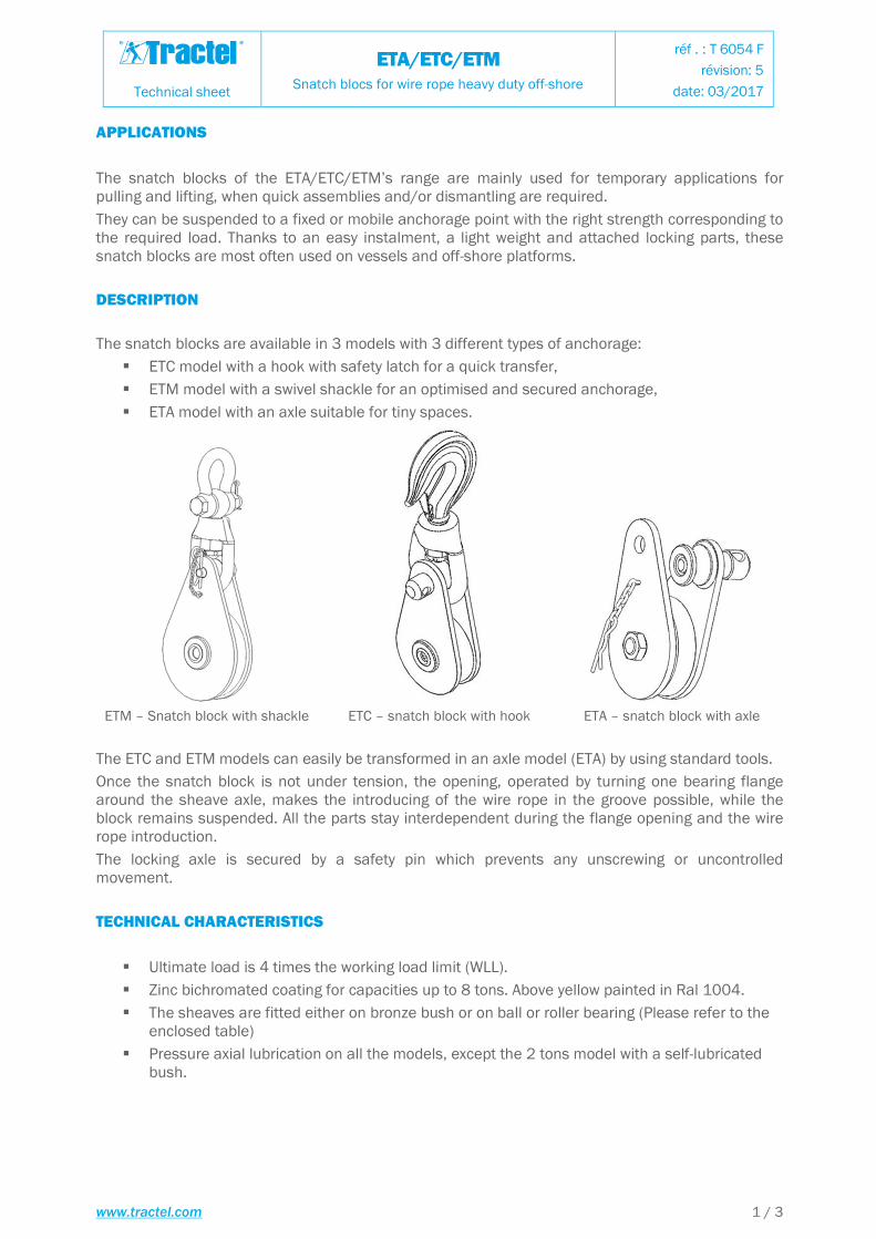
The snatch blocks are available in 3 models with 3 different types of anchorage:
� ETC model with a hook with safety latch for a quick transfer,
� ETM model with a swivel shackle for an optimised and secured anchorage,
� ETA model with an axle suitable for tiny spaces.
ETM – Snatch block with shackle ETC – snatch block with hook ETA – snatch block with axle
The ETC and ETM models can easily be transformed in an axle model (ETA) by using standard tools.
Once the snatch block is not under tension, the opening, operated by turning one bearing flange around the sheave axle, makes the introducing of the wire rope in the groove possible, while the block remains suspended. All the parts stay interdependent during the flange opening and the wire rope introduction.
The locking axle is secured by a safety pin which prevents any unscrewing or uncontrolled movement.
TECHNICAL CHARACTERISTICS
� Ultimate load is 4 times the working load limit (WLL).
� Zinc bichromated coating for capacities up to 8 tons. Above yellow painted in Ral 1004.
� The sheaves are fitted either on bronze bush or on ball or roller bearing (Please refer to the enclosed table)
� Pressure axial lubrication on all the models, except the 2 tons model with a self-lubricated bush.
Technical sheet
ETA/ETC/ETM Snatch blocs for wire rope heavy duty off-shore
ETA/ETC/ETM Snatch blocs for wire rope heavy duty off-shore
réf . : T 6054 F
révision: 5
date: 03/2017
www.tractel.com 3 / 3
NON-CONFORM USES
� NEVER USE FOR PERSONNEL LIFTING.
� Strictly forbidden to either be under or to walk under the load.
� The block should be regularly inspected (priory checking: parts correctly assembled, no excessive movement, no excessive wearing or corrosion, no deformation, no weld corrosion or cracking, free rotating sheave).
� Prior to using the block, check for proper position and locking of the axles. Threaded axle head should be visible after application of nuts.
� Never use a block with a hook as headfitting without ensuring that the safety latch is correctly operated and free from deformation.
� For lifting operations, the user must refer to the safety rules and regulations applicable to this use.
WIRE ROPE STRENGTH REDUCTION
The ratio between the pitch diameter of the sheave and the wire rope diameter, called the winding ratio, alters the tensile strength in the wire rope as hereafter:
Winding ratioWinding ratioWinding ratioWinding ratio ReductionReductionReductionReduction
6 21%
8 17%
10 14%
15 11%
20 9%
Above values are given for information only, depending on the construction of the wire rope.
For more information, please ask your wire rope supplier.
Maximal effort applied on the headfitting of the blockMaximal effort applied on the headfitting of the blockMaximal effort applied on the headfitting of the blockMaximal effort applied on the headfitting of the block
The maximal effort applied on the suspension depends on the load and on the α angle formed between the fall of the load and the fall on which this effort is applied. The resultant value must be The resultant value must be The resultant value must be The resultant value must be strictly lower to the working load limit ofstrictly lower to the working load limit ofstrictly lower to the working load limit ofstrictly lower to the working load limit of the block and the resistance of the anchorage point where the block and the resistance of the anchorage point where the block and the resistance of the anchorage point where the block and the resistance of the anchorage point where the block is fitted.the block is fitted.the block is fitted.the block is fitted.
Please refer to the table and sketch hereunder indicated:
αααα angleangleangleangle Effort applied on the suspensionEffort applied on the suspensionEffort applied on the suspensionEffort applied on the suspension