32
Technical evaluation of Siemens Mammomat Inspiration digital breast tomosynthesis system NHSBSP Equipment Report 1306 version 2 January 2015
| Date post: | 31-Mar-2018 |
| Category: |
Documents |
| Upload: | nguyendung |
| View: | 266 times |
| Download: | 4 times |

Technical evaluation of Siemens Mammomat Inspiration digital breast tomosynthesis system
NHSBSP Equipment Report 1306 version 2 January 2015

Technical evaluation of Siemens Mammomat Inspiration digital breast tomosynthesis system
About the NHS Cancer Screening Programmes
The national office of the NHS Cancer Screening Programmes is operated by Public
Health England. Its role is to provide national management, coordination and quality
assurance of the three cancer screening programmes for breast, cervical and bowel
cancer.
The NHS Cancer Screening Programmes are part of Public Health England (PHE), an
executive agency of the Department of Health.
www.gov.uk/phe
Lead authors:
CJ Strudley, LM Warren, KC Young
© Crown copyright 2015
You may re-use this information (excluding logos) free of charge in any format or
medium, under the terms of the Open Government Licence v3.0. To view this licence,
visit OGL or email [email protected]. Where we have identified any third
party copyright information you will need to obtain permission from the copyright holders
concerned. Any enquiries regarding this publication should be sent to Mary Greatorex:
Published: January 2015
PHE publications gateway number: 2014633

Technical evaluation of Siemens Mammomat Inspiration digital breast tomosynthesis system
3
Document lnformation
Title Technical evaluation of Siemens
Mammomat Inspiration digital breast
tomosynthesis system
Policy/document type Equipment Report 1306
Electronic publication date January 2015
Version 2
Superseded publications Version 1
Review date None
Author/s CJ Strudley
LM Warren
KC Young
Owner NHSBSP
Document objective
(clinical/healthcare/social
questions covered)
To provide an evaluation of this
equipment’s suitability for use within
the NHSBSP
Population affected Women eligible for routine and higher-
risk breast screening
Target audience Physicists, radiographers, radiologists
Date archived Current

Technical evaluation of Siemens Mammomat Inspiration digital breast tomosynthesis system
4
Contents
Contents 4
Acknowledgements 5
Executive summary 6
1. Introduction 7
1.1 Testing procedures and performance standards for digital mammography 7
1.2 Objectives 7
2. Methods 8
2.1 System tested 8
2.2 Dose and contrast to noise ratio under AEC 10
2.3 Image quality measurements 12
2.4 Geometric distortion and reconstruction artefacts 13
2.5 Alignment 15
3. Results 16
3.1 Output and HVL 16
3.2 Dose and CNR 16
3.3 Image quality measurements 21
3.4 Geometric distortion and resolution between focal planes 22
3.5 Alignment 26
4. Discussion 28
4.1 Dose and CNR 28
4.2 Image quality 28
4.3 Geometric distortion and reconstruction artefacts 29
4.4 Alignment 30
5. Conclusions 31
References 32

Technical evaluation of Siemens Mammomat Inspiration digital breast tomosynthesis system
5
Acknowledgements
The authors are grateful to the staff at Derriford Hospital, Plymouth, for their assistance during
the evaluation of the unit at their site.
The contribution made by P Looney of the National Coordinating Centre for the Physics of
Mammography (NCCPM), who wrote software for the data analysis, is also acknowledged.

Technical evaluation of Siemens Mammomat Inspiration digital breast tomosynthesis system
6
Executive summary
The technical performance of the Siemens Mammomat Inspiration digital breast tomosynthesis
system was tested in both 2D and tomosynthesis modes. 2D performance met current
NHSBSP standards for digital mammography. No performance standards have yet been set for
digital breast tomosynthesis systems.
The mean glandular dose to the standard breast was measured in tomosynthesis mode and
found to be within the dose limits for 2D mammography. This report also provides baseline
measurements on other aspects of the equipment performance, including image quality, noise,
spatial distortion and alignment.

Technical evaluation of Siemens Mammomat Inspiration digital breast tomosynthesis system
7
1. Introduction
1.1 Testing procedures and performance standards for digital mammography
Testing procedures and performance standards for conventional 2D mammography are well
established and documented1, 2 but there were not at the time of testing any nationally agreed
procedures and standards for digital breast tomosynthesis (DBT) systems. The tests of
tomosynthesis performance employed for this evaluation were based on those used for the
TOMMY trial.3 A national QC testing protocol has since been published.4
The technical performance of a 2D Siemens Mammomat Inspiration system has previously
been assessed and reported.5 For this evaluation, some of the tests in 2D mode were
repeated.
Research to assess the clinical effectiveness of tomosynthesis is ongoing and further work will
be required to establish measures of technical performance which indicate acceptable clinical
performance. The results of these tomosynthesis performance tests may allow comparisons
between different systems to be made, but should be interpreted with caution until further
experience in the evaluation of tomosynthesis performance has been gained.
1.2 Objectives
This evaluation of the Siemens Mammomat Inspiration tomosynthesis system had two
objectives. The first was to establish whether its 2D performance met the main standards in the
NHSBSP and European protocols. The second was to provide baseline measurements on the
performance of the system in tomosynthesis mode.
Technical evaluation of Siemens Mammomat Inspiration digital breast tomosynthesis system
8
2. Methods
2.1 System tested
The Inspiration tested was an existing 2D system that had been upgraded to perform digital
breast tomosynthesis (DBT). It employs a tungsten target with a rhodium filter for both
conventional 2D and tomosynthesis imaging. (A molybdenum target and molybdenum filter are
also available for 2D exposures). Tomosynthesis exposures are performed using a large format
paddle which is exclusively for use in tomosynthesis. The breast support table is not flat and
horizontal but slopes very slightly down towards the chest wall edge and towards the left and
right sides.
Two automatic exposure control (AEC) modes are available for both 2D and tomosynthesis:
OpDose, which selects beam quality, based on the compressed breast thickness
(CBT), with automatic selection of the tube load. This mode can be used with
Segmentation either on or off. Segmentation is a facility which adjusts exposures to
optimise the imaging of denser areas
AEC, in which the user selects the beam quality, with automatic selection of the tube
load
In tomosynthesis, for both automatic modes, a preliminary stationary 2D exposure is always
acquired, at a tube angle of zero degrees. This pre-pulse, with a tube load of 5mAs, is used to
calculate the tube load for the tomosynthesis exposure.
There is also a manual mode in which the operator can manually select the tube load for a
tomosynthesis exposure.
During a tomosynthesis acquisition the X-ray tube rotates about a centre of rotation which is
30mm above centre of the breast support table. The tube moves to a starting position at a tube
angle of zero degrees, and the pre-pulse is performed with the tube stationary. The tube then
moves into position, starting at an angle of approximately -25° for the first projection. 25
projections are acquired, at intervals of approximately two degrees, with the tube in motion. The
calculated tube load is divided equally between the projections. Collimation is dynamic and
adjusts during the tomosynthesis acquisition to restrict the radiation field to the detector, which
remains stationary. The grid is not used during tomosynthesis.
As well as acquiring 2D images or tomosynthesis images separately, the system can perform a
‘2D / 3D’ exposure, in which a 2D view is followed by a tomosynthesis exposure, during the
same compression.

Technical evaluation of Siemens Mammomat Inspiration digital breast tomosynthesis system
9
OpDose mode was used to select the beam quality for all the tests which involved automatic
selection of exposure factors. Segmentation was then turned off, which allowed the system to
switch into AEC mode, while retaining the selected beam quality settings. (Segmentation is not
appropriate for use when imaging QC phantoms.) The system tested had the standard AEC
dose setting for 2D, with the dose for tomosynthesis set at approximately double the 2D dose.
For this evaluation, images were acquired using the Physics QC Raw format. This produces
three types of image for each tomosynthesis exposure: raw projections, processed projections
and reconstructed planes.
Reconstructed planes are 1mm apart, and the number reconstructed is the CBT in mm +1. A
maximum of 100 planes can be reconstructed. If a tomosynthesis scan is performed on a
greater thickness, a warning is given that only the bottom 100mm will be reconstructed.
Details of the system tested are given in Table 1.
Table 1. System description
Manufacturer Siemens
Model Mammomat Inspiration
System serial number 006-SPH0029230
Target material Tungsten
Added filtration 50µm rhodium
Detector type Amorphous selenium
Pixel size 85µm
Detector area 240mm x 300mm
Pixel array 2816 x 3584
Pixel value offset 50
AEC Modes OpDose, AEC
AEC pre-exposure pulse 5mAs
Tomosynthesis projections 25 equal dose projections at approximately 2º
intervals from -25 to +25º
Reconstructed focal planes Vertical intervals: 1mm
Number of planes : CBT in mm +1 (maximum 100)
Software version VB30B(VX14F) (SL103P104)\/ syngo VE32C SL34P39
VB30B(VX14F) SL103 PACK P104\Aws SW versions\Aws\
device\ versions
QC images were downloaded from the acquisition workstation via a USB port. The
tomosynthesis images were in the DICOM6 CT format. Individual reconstructed focal planes or
projections, as well as the complete set of images from the tomosynthesis exposure, could be
selected for export. Typical image file sizes are shown in Table 2.
Technical evaluation of Siemens Mammomat Inspiration digital breast tomosynthesis system
10
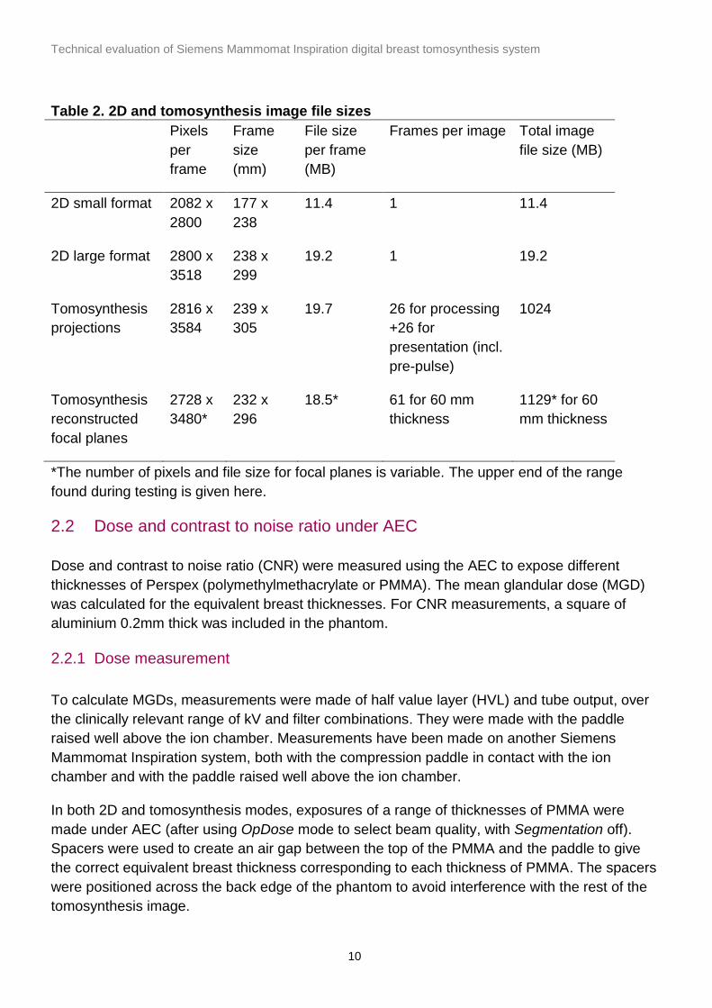
Table 2. 2D and tomosynthesis image file sizes
Pixels
per
frame
Frame
size
(mm)
File size
per frame
(MB)
Frames per image Total image
file size (MB)
2D small format 2082 x
2800
177 x
238
11.4 1 11.4
2D large format 2800 x
3518
238 x
299
19.2 1 19.2
Tomosynthesis
projections
2816 x
3584
239 x
305
19.7 26 for processing
+26 for
presentation (incl.
pre-pulse)
1024
Tomosynthesis
reconstructed
focal planes
2728 x
3480*
232 x
296
18.5* 61 for 60 mm
thickness
1129* for 60
mm thickness
*The number of pixels and file size for focal planes is variable. The upper end of the range
found during testing is given here.
2.2 Dose and contrast to noise ratio under AEC
Dose and contrast to noise ratio (CNR) were measured using the AEC to expose different
thicknesses of Perspex (polymethylmethacrylate or PMMA). The mean glandular dose (MGD)
was calculated for the equivalent breast thicknesses. For CNR measurements, a square of
aluminium 0.2mm thick was included in the phantom.
2.2.1 Dose measurement
To calculate MGDs, measurements were made of half value layer (HVL) and tube output, over
the clinically relevant range of kV and filter combinations. They were made with the paddle
raised well above the ion chamber. Measurements have been made on another Siemens
Mammomat Inspiration system, both with the compression paddle in contact with the ion
chamber and with the paddle raised well above the ion chamber.
In both 2D and tomosynthesis modes, exposures of a range of thicknesses of PMMA were
made under AEC (after using OpDose mode to select beam quality, with Segmentation off).
Spacers were used to create an air gap between the top of the PMMA and the paddle to give
the correct equivalent breast thickness corresponding to each thickness of PMMA. The spacers
were positioned across the back edge of the phantom to avoid interference with the rest of the
tomosynthesis image.

Technical evaluation of Siemens Mammomat Inspiration digital breast tomosynthesis system
11
Doses in 2D mode were calculated as described in the UK protocol. Doses in tomosynthesis
mode were calculated using the method described by Dance et al.7 This is an extension of the
established 2D method, using the equation:
(1)
Where K is the incident air kerma at the top surface of the breast, and g, c and s are conversion
factors. The additional factor, T, is derived by summing weighted correction factors for each of
the tomosynthesis projections. Values of T are tabulated for the Siemens Mammomat
Inspiration system for different compressed breast thickness.
The Dance method of calculating MGD uses a measured dose at the surface of the breast with
the paddle in place, but the method described in the UK protocol differs in that dose is
measured with the paddle raised well above the ion chamber. To allow comparisons to be
made between systems, MGD results in this report are calculated with the paddle raised. A
correction factor is provided, which may be used to obtain a more accurate calculation of MGD.
2.2.2 Contrast to noise ratio
For CNR measurements a 10mm x 10mm square of 0.2mm thick aluminium foil was included in
the phantom described above, positioned 10mm above the table on the midline, 60mm from the
chest wall edge.
CNR in the 2D images was assessed using 5mm x 5mm regions of interest (ROIs) positioned
in the centre of the aluminium square and at two background positions at the chest wall and
nipple sides of the square.
CNR in the tomosynthesis focal plane was measured using 5mm x 5mm ROIs placed at the
same positions as for the 2D image, as shown in Figure 1. The CNR was measured in the focal
plane containing the aluminium square and in two planes above and two further planes below.
The result quoted is the average of the measurements from all five planes.
CNR was also assessed in the unprocessed tomosynthesis projections acquired for the above
images, using a 5mm x 5mm ROI.

Technical evaluation of Siemens Mammomat Inspiration digital breast tomosynthesis system
12
Figure 1. The positioning of 5mm x 5mm ROIs for measurement of CNR in
tomosynthesis
Variation of tomosynthesis CNR with dose was assessed both in the projections and in the
reconstructed image for an equivalent breast thickness of 53mm (that is, using a 45mm
thickness of PMMA).
2.3 Image quality measurements
Image quality was assessed in 2D mode using a CDMAM phantom. In the absence of a more
suitable test object for assessing tomosynthesis imaging performance, images of the CDMAM
were also acquired in tomosynthesis mode. The CDMAM phantom (Version 3.4, serial number
1022) was sandwiched between two blocks of PMMA, each 20mm thick. The exposure factors
used were the same as those selected by the AEC for an equivalent breast thickness of 60mm.
One set of sixteen images was acquired in 2D mode at the AEC selected dose. In
tomosynthesis mode, one set of sixteen images was acquired at the AEC selected dose and a
further set at double this dose.
For the tomosynthesis exposures, the chest wall edge of the phantom was raised by 3mm so
that the plane of the CDMAM would be parallel to the reconstructed focal planes in the
reconstructed image (see geometric distortion results in section 3.4.1).
From the tomosynthesis images, the focal plane in best focus was selected. This was at the
height of the CDMAM above the breast support table. The set of 2D images and the two sets of
tomosynthesis images were read and analysed using two software tools, CDCOM version 1.6*
and CDMAM Analysis version 1.4.† This was repeated using the planes immediately above and
*CDCOM version 1.6. Available from EUREF website: www.euref.org. Accessed 4 July 2013. †CDMAM analysis UK v1.4, NCCPM, Guildford, UK

Technical evaluation of Siemens Mammomat Inspiration digital breast tomosynthesis system
13
below the expected plane of best focus to ensure that the CDMAM result quoted corresponded
to the best image quality obtained.
2D image quality assessed using the CDMAM is for an equivalent breast thickness of 60 mm.
This can be related to the image quality at other thicknesses by using the CNRs measured for a
range of thicknesses. The European protocol2 gives the relationship between threshold contrast
and CNR measurements, enabling calculation of a target CNR value for a particular level of
image quality. This can be compared to CNR measurements for other breast thicknesses.
Contrast for a particular gold thickness is calculated using Equation 2, and target CNR is
calculated using Equation 3.
(2)
where µ is the effective attenuation coefficient for gold, and t is the gold thickness.
(3)
where CNRmeasured is the CNR for a 60mm equivalent breast, TCmeasured is the threshold contrast
calculated using the threshold gold thickness for a 0.1mm diameter detail (measured using the
CDMAM at the same dose as used for CNRmeasured), and TCtarget is the calculated threshold
contrast corresponding to the threshold gold thickness required to meet either the minimum
acceptable or achievable level of image quality.
The European protocol2 also defines a limiting value for CNR, which is a percentage of the
threshold contrast for minimum acceptable image quality for each thickness. The target CNR
values for minimum acceptable and achievable levels of image quality and European limiting
values for CNR were calculated.
2.4 Geometric distortion and reconstruction artefacts
The relationship between reconstructed tomosynthesis focal planes and the geometry of the
volume that they represent was assessed. This was done by imaging a geometric test phantom
consisting of a rectangular array of 1mm diameter aluminium balls, 50mm apart, in the middle
of a 5mm thick sheet of PMMA. The phantom was placed at various heights (7.5, 32.5 and
57.5mm) within a 60mm stack of plain sheets of PMMA on the breast support table.
Reconstructed tomosynthesis planes were analysed to the find the height of the focal plane in
which each ball was best in focus, the position of the centre of the ball within that plane, the
number of adjacent planes in which the ball was also seen, and to quantify the variation in
appearance of the ball between focal planes.
Technical evaluation of Siemens Mammomat Inspiration digital breast tomosynthesis system
14
This analysis was automated through the use of an ImageJ‡ plug-in, developed by NCCPM for
this purpose.
2.4.1 Height of best focus
For each ball, the height of the focal plane in which it was best in focus was identified. Results
were compared for all balls in each image, to determine whether there was any tilt of the test
phantom relative to the reconstructed planes, or any vertical distortion of the focal planes within
the image.
2.4.2 Positional accuracy within focal plane
The x and y co-ordinates within the image were found for each ball. (The x and y directions are
perpendicular and parallel to the chest wall edge, respectively). The mean distances between
adjacent balls were calculated, using the pixel spacing quoted in the DICOM header. This was
compared to the physical separation of balls within the phantom, to assess the scaling
accuracy in the x and y directions. The maximum deviations from the mean x and y separations
were calculated, to indicate whether there was any discernible distortion of the image within the
focal plane.
2.4.3 Appearance of the ball in adjacent focal planes
Changes to the appearance of a ball in different focal planes were assessed visually.
To quantify the extent of reconstruction artefacts in adjacent focal planes, the reconstructed
image was treated as though it were a true three dimensional volume. The ImageJ plug-in was
used to find the x, y, and z dimensions of a rectangular volume around each ball which
enclosed all pixels with values exceeding 50% of the maximum pixel value. The method used
was to create a composite x-y image using the maximum pixel values from all focal planes. A
composite x line was then created using the maximum pixel from each column of the x-y
composite plane. The full width at half maximum (FWHM) measurement in the x direction was
made by fitting a polynomial spline. This was repeated in the orthogonal direction to produce
the y-FWHM, and again using vertical re-sliced planes to find the z-FWHM. All pixel values
were background subtracted, using the mean pixel value from around the ball in the plane of
best focus. The composite z-FWHM thus calculated was used as a measure of the inter-plane
resolution, or z-resolution. Its value would be different if a ball of different size were used.
The FWHM in the x and y directions of the image of the ball were also measured in the plane of
best focus, in order to compare with the composite x- and y-FWHM measurements. This
allowed quantification of any apparent shift or spread in the appearance of the ball through a
series of adjacent focal planes.
‡ http://rsb.info.nih.gov/ij/

Technical evaluation of Siemens Mammomat Inspiration digital breast tomosynthesis system
15
2.5 Alignment
Alignment measurements were carried out for reconstructed tomosynthesis images.
The alignment of the X-ray beam to one focal plane of the reconstructed tomosynthesis volume
was assessed at the height of the centre of rotation of the X-ray beam, 30mm above the
surface of the breast support table. Self-developing film and graduated markers were supported
at the required height and positioned on each edge of the X-ray beam. The alignment at the
lateral edges could only be measured at this height because at other heights the movement of
the tube during the scan would cause the lateral edges of the X-ray beam to move between
projections.
The alignment of the imaged volume to the compressed volume was also assessed. Missed
tissue at the chest wall edge was assessed at the height of the surface of the breast support
table using a graduated marker. Small high contrast markers were placed on the breast support
table and on the underside of the compression paddle to assess vertical alignment. The image
planes were then inspected to determine whether all markers were brought into focus within the
reconstructed volume.

Technical evaluation of Siemens Mammomat Inspiration digital breast tomosynthesis system
16
3. Results
3.1 Output and HVL
The tube output and HVL results are shown in Table 3. The paddle was in the beam and was
raised well above the ion chamber. Measurements that had been made on another Siemens
Mammomat Inspiration system, showed that the dose measured with the paddle in contact with
the upper surface of the ion chamber was 4.5% higher than that measured with the paddle
raised well above the ion chamber. A correction factor of 1.045 would therefore be applied to
the output measurements in Table 3 and the MGDs in section 3.2, if scatter from the paddle
were to be taken into account.
Table 3. HVL and tube output measurement
kV Target Filter Tube output
(µGy/mAs at
1m)
HVL (mm)
25 W Rh 8.93 0.52
28 W Rh 12.5 0.55
31 W Rh 15.9 0.58
34 W Rh 19.3 0.61
3.2 Dose and CNR
The MGDs calculated for 2D and tomosynthesis modes are shown in Tables 4 and 5, and
presented graphically in Figure 2. The correction factor of 1.045 has not been applied.
Table 4. Dose and CNR for 2D images acquired under AEC
PMMA
(mm)
Equivalent
breast
thickness
(mm)
kV Target /
filter
mAs MGD*
(mGy)
NHSBSP
dose limit
(mGy)
CNR
20 21 26 W / Rh 33 0.45 1.0 9.3
30 32 27 W / Rh 49 0.62 1.5 8.5
40 45 28 W / Rh 74 0.86 2.0 7.8
45 53 29 W / Rh 83 0.99 2.5 7.3
50 60 30 W / Rh 94 1.16 3.0 7.0
60 75 31 W / Rh 134 1.60 4.5 6.1
70 90 32 W / Rh 185 2.11 6.5 5.3
*The mAs and MGD values quoted include the pre-exposure pulse (tube load 5mAs), which is
not included in the image.

Technical evaluation of Siemens Mammomat Inspiration digital breast tomosynthesis system
17
The CNR measurements for 2D images are shown in Table 4. Table 5 shows the measured
CNRs for the reconstructed tomosynthesis images and for the central (zero degree) 2D
projection images. The dose for an individual projection is 1/25 of the total dose from a
tomosynthesis acquisition.
Table 5. Dose and CNR for tomosynthesis images acquired under AEC
PMMA
(mm)
Equivalent
breast
thickness
(mm)
kV Target /
filter
mAs* MGD*
(mGy)
CNR in
reconstructed
tomosynthesis
image
CNR in
central
projection
20 21 26 W / Rh 72 0.95 1.85 2.87
30 32 27 W / Rh 104 1.26 1.58 2.40
40 45 28 W / Rh 150 1.67 1.34 2.06
45 53 29 W / Rh 167 1.90 1.21 1.87
50 60 30 W / Rh 185 2.18 1.13 1.72
60 75 31 W / Rh 252 2.87 0.93 1.46
70 90 32 W / Rh 329 3.58 0.75 1.36
*The mAs and MGD values quoted include the pre-exposure pulse (tube load 5mAs), which is
not included in the reconstructed tomosynthesis image.
Figure 2. MGD for 2D and tomosynthesis images under AEC. (Error bars indicate 95%
confidence limits.)
0 20 40 60 80 1000
2
4
6
8
2D MGD (mGy)
Remedial dose limit
Tomo MGD (mGy)
Equivalent breast thickness (mm)
MG
D (
mG
y)
Technical evaluation of Siemens Mammomat Inspiration digital breast tomosynthesis system
18
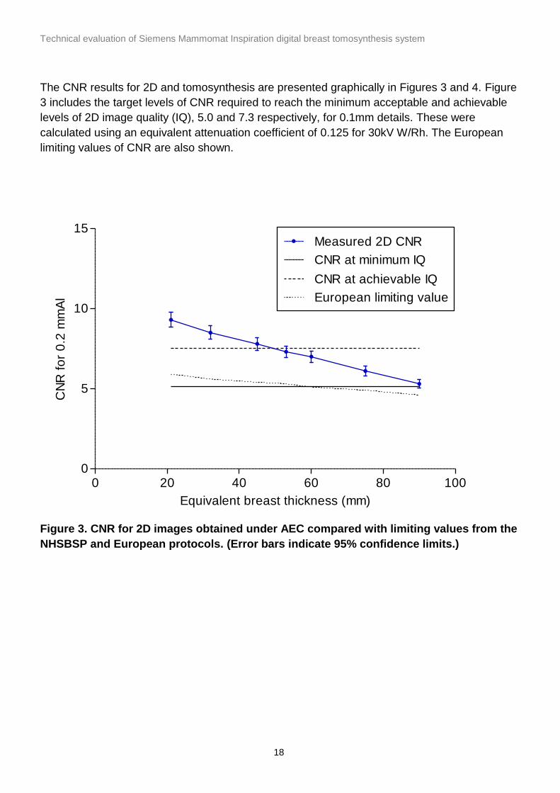
The CNR results for 2D and tomosynthesis are presented graphically in Figures 3 and 4. Figure
3 includes the target levels of CNR required to reach the minimum acceptable and achievable
levels of 2D image quality (IQ), 5.0 and 7.3 respectively, for 0.1mm details. These were
calculated using an equivalent attenuation coefficient of 0.125 for 30kV W/Rh. The European
limiting values of CNR are also shown.
Figure 3. CNR for 2D images obtained under AEC compared with limiting values from the
NHSBSP and European protocols. (Error bars indicate 95% confidence limits.)
0 20 40 60 80 1000
5
10
15Measured 2D CNR
CNR at minimum IQ
CNR at achievable IQ
European limiting value
Equivalent breast thickness (mm)
CN
R f
or
0.2
mm
Al

Technical evaluation of Siemens Mammomat Inspiration digital breast tomosynthesis system
19
Figure 4. CNR for tomosynthesis images obtained under AEC. (Error bars indicate 95%
confidence limits.)
The variation of tomosynthesis CNR with dose is shown in Table 6 and Figure 5. A power fit
was applied to the relationship between CNR and dose for reconstructed focal planes and
projections.
Figure 6 shows the variation of projection CNR with tube angle for three thicknesses of PMMA.
Table 6. Variation of tomosynthesis CNR with dose
PMMA
(mm)
Equivalent
breast
thickness
(mm)
kV Target /
filter
mAs MGD
(mGy)
CNR in
reconstructed
DBT image
CNR in
central
projection
45 53 29 W / Rh 56 0.64 0.61 1.01
45 53 29 W / Rh 90 1.02 0.81 1.30
45 53 29 W / Rh 160 1.82 1.19 1.88
45 53 29 W / Rh 250 2085 1.49 2.37
45 53 29 W / Rh 560 6.38 2.31 3.59
0 20 40 60 80 1000
1
2
3
4
Focal plane
Projection
Equivalent breast thickness (mm)
To
mo
CN
R f
or
0.2
mm
Al

Technical evaluation of Siemens Mammomat Inspiration digital breast tomosynthesis system
20
Figure 5. CNR measured in tomosynthesis mode, for a 53mm equivalent breast thickness at a range of doses. (Error bars indicate 95% confidence limits.)
Figure 6. CNR measurements in tomosynthesis projections for three different PMMA thicknesses
0 2 4 6 80
1
2
3
4
5Focal plane
y=0.82x0.56
Projection
y=1.33x0.54
MGD (mGy)
To
mo
CN
R f
or
0.2
mm
Al
-30 -20 -10 0 10 20 300
1
2
3
4
45mm PMMA
20mm PMMA
70mm PMMA
Angle (degrees)
To
mo
Pro
ject
ion
CN
R f
or
0.2
mm
Al

Technical evaluation of Siemens Mammomat Inspiration digital breast tomosynthesis system
21
3.3 Image quality measurements
The contrast detail curve for sixteen 2D images is shown in Figure 7.
Figure 7. Threshold gold thicknesses for 2D images acquired at 30kV W/Rh. (Error bars indicate 95% confidence limits.)
Figure 8. Threshold gold thicknesses for tomosynthesis images acquired at two doses, at 30kV W/Rh. (Error bars indicate 95% confidence limits.)
0.01
0.1
1
10
0.10 0.13 0.16 0.20 0.25 0.31 0.40 0.50 0.63 0.80 1.00
Acceptable
Achievable
MGD = 1.11 mGy (AEC dose)
Diameter (mm)
Thre
sho
ld g
old
thic
kne
ss (
m)
0.01
0.1
1
10
0.10 0.13 0.16 0.20 0.25 0.31 0.40 0.50 0.63 0.80 1.00
Acceptable for 2D
Achievable for 2D
MGD = 2.13 mGy (AEC dose)
MGD = 4.25 mGy
Diameter (mm)
Thre
sho
ld g
old
thic
kne
ss (
m)

Technical evaluation of Siemens Mammomat Inspiration digital breast tomosynthesis system
22
In Figure 8, CDMAM curves are shown for sets of 16 images, assessed using the plane in best
focus from each set. Results are for the AEC selected dose and for twice this dose.
The image quality results shown in Figures 7 and 8 are summarised in Table 7.
Table 7. Average threshold gold thicknesses for CDMAM images in 2D and
tomosynthesis
Threshold gold thickness (µm)
Detail diameter (mm)
2D AEC dose 1.11 mGy
DBT AEC dose 2.13mGy
DBT double AEC dose 4.25mGy
Minimum standard for 2D
Achievable standard for 2D
0.10 1.191 2.495 1.791 1.680 1.100 0.25 0.255 0.414 0.313 0.352 0.244 0.50 0.120 0.165 0.121 0.150 0.103 1.00 0.061 0.090 0.078 0.091 0.056
3.4 Geometric distortion and resolution between focal planes
3.4.1 Height of best focus
For each of the three images, acquired at different heights, the height of best focus for each
ball was found to increase with distance from the chest wall edge. The mean gradient was
0.018, corresponding to a height differential of 3mm over a distance of 170mm. This indicates
that the reconstructed focal planes are aligned to the horizontal plane rather than to the slightly
inclined surface of the breast support table.
At the chest wall edge of the image the height of best focus for each ball was found to be within
1mm of its height above the table. For each set of balls at the same distance from the chest
wall edge the height variation was no greater than 1mm, indicating that the focal planes are flat
and horizontal.
3.4.2 Positional accuracy within focal plane
The mean distances between balls, calculated using the pixel spacings from the DICOM
headers, were 50.0mm in both x and y directions. The true separation between balls was
50.0mm, indicating no scaling error in either direction. The maximum deviation from the mean
separations was 0.1mm in both x and y directions, while the test object’s manufacturing
specification was a non-cumulative positioning accuracy of ± 0.1mm. These results indicate
that there is no discernible geometric distortion within the focal plane.

Technical evaluation of Siemens Mammomat Inspiration digital breast tomosynthesis system
23
3.4.3 Appearance of the ball in adjacent focal planes
The image of a 1mm diameter aluminium ball is well defined in the plane of best focus, but
appears flattened with a dark area (reduced pixel value) to either side in the y direction (parallel
to the chest wall edge), as shown in the middle frame of the second row in Figure 9. In focal
planes above and below, the image of the ball becomes longer and fainter, and stretches into a
line, as shown in Figure 9. There is also a slight shift in the direction perpendicular to the chest
wall edge. The views shown are taken at 1mm intervals, from 7mm below to 7mm above the
plane at the same height as the ball.
Figure 10 shows the focal planes re-sliced into vertical planes in the x-z and y-z orientations.
-7mm -6mm -5mm -4mm -3mm
-2mm -1mm 0mm +1mm +2mm
+3mm +4mm +5mm +6mm +7mm
Figure 9. Appearance in focal planes at different heights of a 1mm aluminium ball,
110mm from the chest wall edge, in the central area of a tomosynthesis image.
Figure 10. Vertically resliced planes through the centre of a 1mm aluminium ball, 110mm
from the chest wall edge, in the central area of a tomosynthesis image. The x-z plane is
on the left and the y-z plane is on the right.

Technical evaluation of Siemens Mammomat Inspiration digital breast tomosynthesis system
24
Table 8 shows the results of the automated analysis of the images. The x- and y-FWHM from
the plane of best focus, and the composite FWHM (from all planes) are shown. The difference
between these quantities indicates the apparent shift or spread of the image between planes.
Table 8. Mean dimensions and range (in brackets) of FWHM, for 1mm diameter
aluminium balls and their associated reconstruction artefacts.
FWHM within plane of
best focus (mm)
Composite FWHM
using all planes
(mm)
Apparent shift or
spread between focal
planes (mm)
x (perpendicular to
chest wall edge)
0.89
(0.83 to 0.96)
1.14
(0.86 to 1.53)
0.26
(0.01 to 0.65)
y (parallel to chest
wall edge)
0.71
(0.62 to 0.79)
0.85
(0.67 to 1.23)
0.14
(0.00 to 0.47)
z (vertical)
3.9
(3.6 to 4.3)
The variations of the measurements for individual balls with position within the reconstructed
image are presented graphically in Figures 11 to 13.
Figure 11 shows that the composite x-FWHM (in the direction perpendicular to the chest wall
edge) increases with distance from the edge. Figure 12 shows that the composite y-FWHM
increases with distance from the centre of the midline.
The composite z-FWHM measurements give a measure of the inter-plane or z-resolution for the tomosynthesis image. Figure 13 shows no significant dependence of z-FWHM on position within the image.

Technical evaluation of Siemens Mammomat Inspiration digital breast tomosynthesis system
25
Figure 11. Composite FWHM in the x-direction (perpendicular to the chest wall edge)
plotted against distance from the chest wall edge.
Figure 12. Composite FWHM in the y-direction (parallel to the chest wall edge) plotted
against distance from the midline.
0 50 100 150 200 2500.0
0.5
1.0
1.5
2.0
Distance from CWE (mm)
X F
WH
M (
mm
)
-200 -100 0 100 2000.0
0.5
1.0
1.5
2.0
Distance from midline (mm)
Y F
WH
M (
mm
)

Technical evaluation of Siemens Mammomat Inspiration digital breast tomosynthesis system
26
Figure 13. Composite FWHM in the z- direction (vertical) plotted against distance from
the chest wall edge.
3.5 Alignment
Table 9 shows the alignment of the X-ray field to the reconstructed image at the height of the
centre of rotation, 30mm above the surface of the breast support table. The X-ray field overlaps
the edges of the reconstructed image by less than 5mm, which is the limit applied in 2D
mammography.
Table 9. Alignment of X-ray field to reconstructed tomosynthesis image
Height above table (mm) X-ray field to reconstructed tomosynthesis image* (mm)
Front Back Left Right
0 1
30 1.5 3 0 1
80 1
*A positive value indicates that the X-ray field overlaps the edge of the image
The alignment of the reconstructed volume to the compressed volume was assessed. The
amount of missed tissue at the chest wall edge was 4mm at the surface of the breast support
table. This is within the 5mm limit which is applied in 2D mammography.
All markers distributed in the central area of the surface of the breast support table and the
underside of the compression paddle were brought into focus in planes near the bottom and top
of the image. This showed that no details are missed at the base or top of the reconstructed
volume in the central area. However, due to the slope of the breast support table (as noted in
0 50 100 150 200 2500
2
4
6
Distance from CWE (mm)
Z F
WH
M (
mm
)

Technical evaluation of Siemens Mammomat Inspiration digital breast tomosynthesis system
27
section 3.4.1), it is anticipated that the lowest 2mm of tissue near the chest wall edge, will be
left out of the reconstructed volume. The same may apply to a few mm of tissue at the top, as
the compression paddle tends to tilt. Small details at the top and bottom of the chest wall edge
will, therefore, not be brought into sharp focus in any focal plane.

Technical evaluation of Siemens Mammomat Inspiration digital breast tomosynthesis system
28
4. Discussion
4.1 Dose and CNR
The MGDs to the standard breast were calculated for a range of equivalent breast thicknesses
from 20mm to 90mm. In both 2D and tomosynthesis modes the doses were well within the
NHSBSP dose limits for 2D mammography (except for the smallest equivalent breast
thickness, where the tomosynthesis dose is close to the limit). The MGD to a 53mm equivalent
breast thickness was 0.99mGy and 1.90mGy for 2D and tomosynthesis respectively, while the
NHSBSP dose limit for 2D mammography is 2.5mGy for this thickness.
In 2D mode under AEC, the CNR for all equivalent breast thicknesses exceeded the value
required to meet the NHSBSP standard for minimum acceptable image quality. The CNR only
exceeded the value required for the achievable level of image quality for equivalent breast
thicknesses of less than 50 mm. This could be improved by increasing the dose under AEC. As
usual in digital mammography, the CNR for 2D imaging decreased significantly as the breast
thickness increased.
CNR values in reconstructed tomosynthesis focal planes are expected to be highly dependent
on the degree of smoothing and scaling inherent within the reconstruction algorithm. Any
interpretation of absolute CNR values in relation to image quality should therefore be treated
with caution. The CNR measured in the focal plane is seen to decrease with breast thickness to
a greater extent than the CNR measured in 2D. This may be largely due to the greater amount
of scatter reaching the detector in the tomosynthesis projections in the absence of a grid.
CNR measurements were also made in the unprocessed tomosynthesis projections. The CNRs
are lower because the dose per projection is a fraction (1/25) of the total dose in
tomosynthesis. The CNR in projections decreased slightly with increasing projection angle. A
variation would be expected due to the change in contrast and noise with increasing angle.
The variation of tomosynthesis CNR with dose was assessed. A power fit applied to the
relationships between CNR and dose had an index close to 0.5 for both reconstructed focal
planes and projections. This indicates that quantum noise is the dominant noise source in the
tomosynthesis images.
4.2 Image quality
Image quality was assessed in 2D mode using the CDMAM test object under AEC. The 2D
threshold gold thickness curve is close to (or a little less than) the achievable level of image
quality for all detail sizes.
No suitable test object has yet been developed for assessing image quality in tomosynthesis.
However, CDMAM images were acquired, under AEC, in tomosynthesis mode. The resulting

Technical evaluation of Siemens Mammomat Inspiration digital breast tomosynthesis system
29
threshold gold thickness curve for tomosynthesis is poorer than the minimum acceptable level
of image quality that is defined for 2D mammography. This result takes no account of the ability
of tomosynthesis to remove the obscuring effects of overlying tissue in a clinical image. The
degree of this effect in different tomosynthesis systems is expected to vary, depending on the
angular range over which projections are acquired. The Inspiration, with a relatively wide
angular range, may be very effective in removing the appearance of overlying tissues. This
would compensate for the relatively poor CDMAM performance compared to 2D imaging. As
expected, the threshold gold thickness decreased when the dose was doubled.
There is no standard test object available yet that would allow a realistic and quantitative
comparison of image quality between tomosynthesis systems, or between 2D and
tomosynthesis modes. A suitable test object would need to incorporate simulated breast tissue
to show the benefit of removing overlying breast structure in tomosynthesis imaging, as
compared to 2D imaging. In the absence of such a test object, an extensive clinical trial would
be needed to determine whether the performance of a particular tomosynthesis system is likely
to be clinically adequate.
4.3 Geometric distortion and reconstruction artefacts
Assessment of geometric distortion images demonstrated that reconstructed tomosynthesis
focal planes are horizontal, rather than parallel to the slightly sloping surface of the breast
support table. There was no vertical distortion. Within the focal plane, comparison of measured
with nominal separations of imaged details demonstrated that there is no geometric distortion.
There is no scaling error in using the pixel spacing quoted in the image DICOM headers.
In the QC Raw tomosynthesis images of 1mm aluminium balls within a PMMA block, the balls
did not appear circular when viewed within the plane of best focus. Instead, they appeared
flattened with a dark area (indicating reduced pixel value), to either side in the y-direction, that
is, parallel to the chest wall edge. The excessive contrast produced by the aluminium ball is the
cause of this artefact. However, it is not necessarily predictive of such artefacts in clinical
images. These have less abrupt changes in contrast and additional image processing is
applied. On viewing successive focal planes away from the plane of best focus, the image of a
ball stretches into a line which fades and changes direction slightly. It also shifts position
slightly in the direction perpendicular to the chest wall edge.
Within focal planes, the spread of reconstruction artefacts associated with balls increased with
distance from the centre of the chest wall edge of the image. Due to the geometry of the
diverging primary X-ray beam, the reconstruction artefacts might be expected to extend further
away from the centre of the chest wall edge of the image with increasing distance from the X-
ray tube focal spot. Measurement of the maximum extent of the 50% contour level in
background corrected pixel values around each ball in all planes quantified the magnification
effect between focal planes. This measurement exceeded that in the plane of best focus by up
to 0.6mm.

Technical evaluation of Siemens Mammomat Inspiration digital breast tomosynthesis system
30
A tomosynthesis system employing a wide range of projection angles, like the Inspiration, is
expected to have good inter-plane resolution with little persistence between focal planes. The
50% contour extended vertically between focal planes, giving a mean inter-plane resolution of
4mm for the 1mm diameter balls. Balls of different diameter would result in more or less
extensive reconstruction artefacts, so the inter-plane resolution would vary accordingly. Inter-
plane resolution did not vary by any more than 10% with vertical or horizontal position of the
balls.
4.4 Alignment
It is not possible to assess the alignment of the irradiated volume to the imaged volume
because the lateral parts of the volume are partially irradiated as the X-ray field moves during
the tomosynthesis scan. At the height of the centre of rotation (30mm above the surface of the
breast support table) the X-ray beam extended beyond the edges of the reconstructed focal
plane by less than the 5mm limit which is applied to 2D mammography.
Assessment of the alignment of the tomosynthesis imaged volume to the compressed volume
indicated that 4mm of tissue is missed at the chest wall edge at the height of the surface of the
breast support table. This is within the 5mm limit for 2D mammography. There was no missed
tissue in the central area at either the top or bottom of the reconstructed image. However, the
table slopes down towards the chest wall edge, and the paddle may tilt slightly upwards during
compression. It is therefore likely that a few mm of tissue at both top and bottom, near the
chest wall edge, would not be brought into sharp focus.

Technical evaluation of Siemens Mammomat Inspiration digital breast tomosynthesis system
31
5. Conclusions
The technical performance was tested in both 2D and tomosynthesis modes. 2D performance
met current NHSBSP standards for digital mammography. No performance standards have yet
been set for digital breast tomosynthesis systems and it is not yet possible to predict clinical
tomosynthesis performance from these results.
The MGD to the standard breast was found to be almost twice as large in tomosynthesis mode
as in 2D mode. Since doses on the Siemens Mammomat Inspiration are quite low in 2D, the
doses in tomosynthesis are still well within the NHSBSP dose limits for 2D mammography. It
would be desirable to increase the doses in 2D mode to improve image quality, especially for
thicker breasts.

Technical evaluation of Siemens Mammomat Inspiration digital breast tomosynthesis system
32
References
1. Kulama E , Burch A, Castellano I et al. Commissioning and Routine Testing of Full Field
Digital Mammography Systems (NHSBSP Equipment Report 0604, Version 3). Sheffield:
NHS Cancer Screening Programmes, 2009
2. Van Engen R, Young KC, Bosmans H et al. The European protocol for the quality control of
the physical and technical aspects of mammography screening. In: European Guidelines for
Quality Assurance in Breast Cancer Screening and Diagnosis, 4th Edition. Luxembourg:
European Commission, 2006.
3. Strudley CJ, Young KC, Oduko JM et al. Development of a Quality Control Protocol for
Digital Breast Tomosynthesis Systems in the TOMMY Trial. In: International Workshop on
Breast Imaging 2012. Berlin: Springer-Verlag, 2012, 330–337.
4. Burch A, Loader R, Rowberry B et al. Routine Quality Control Tests for Breast
Tomosynthesis (Physicists) (NHSBSP Equipment Report 1407). Sheffield: NHS Cancer
Screening Programmes, 2014
5. Young KC, Oduko JM, Gundogdu O et al. Technical Evaluation of Siemens Mammomat
Inspiration Full Field Digital Mammography System (NHSBSP Equipment Report 0909).
Sheffield: NHS Cancer Screening Programmes, 2009
6. Digital Imaging and Communications in Medicine (DICOM) Part 3: Information Object
Definitions. Virginia: National Electrical Manufacturers Association, 2011.
7. Dance DR, Young KC, van Engen RE. Estimation of mean glandular dose for breast
tomosynthesis: factors for use with the UK, European and IAEA breast dosimetry protocols.
Physics in Medicine and Biology, 2011, 56: 453-471.


![MAMMOMAT Revelation...MAMMOMAT Revelation has participated in an industry-wide testing program sponsored by Integrating the Healthcare Enterprise (IHE) [2]. The IHE Integration …](https://static.documents.pub/doc/80x56/60adc72f060fdb7ac16f3e7f/mammomat-revelation-mammomat-revelation-has-participated-in-an-industry-wide.jpg)


