The author(s) shown below used Federal funds provided by the U.S. Department of Justice and prepared the following final report: Document Title: Technical Evaluation of the TRP-1000 and ACU- 1000: Test Procedures and Results Author(s): OLES/Institute for Telecommunication Sciences Document No.: 194698 Date Received: November 2007 Award Number: TE-00-002-01 This report has not been published by the U.S. Department of Justice. To provide better customer service, NCJRS has made this Federally- funded grant final report available electronically in addition to traditional paper copies. Opinions or points of view expressed are those of the author(s) and do not necessarily reflect the official position or policies of the U.S. Department of Justice.
Transcript
The author(s) shown below used Federal funds provided by the US Department of Justice and prepared the following final report Document Title Technical Evaluation of the TRP-1000 and ACU-
1000 Test Procedures and Results
Author(s) OLESInstitute for Telecommunication Sciences
Document No 194698
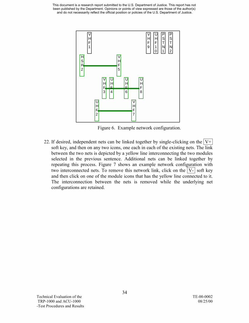
Date Received November 2007
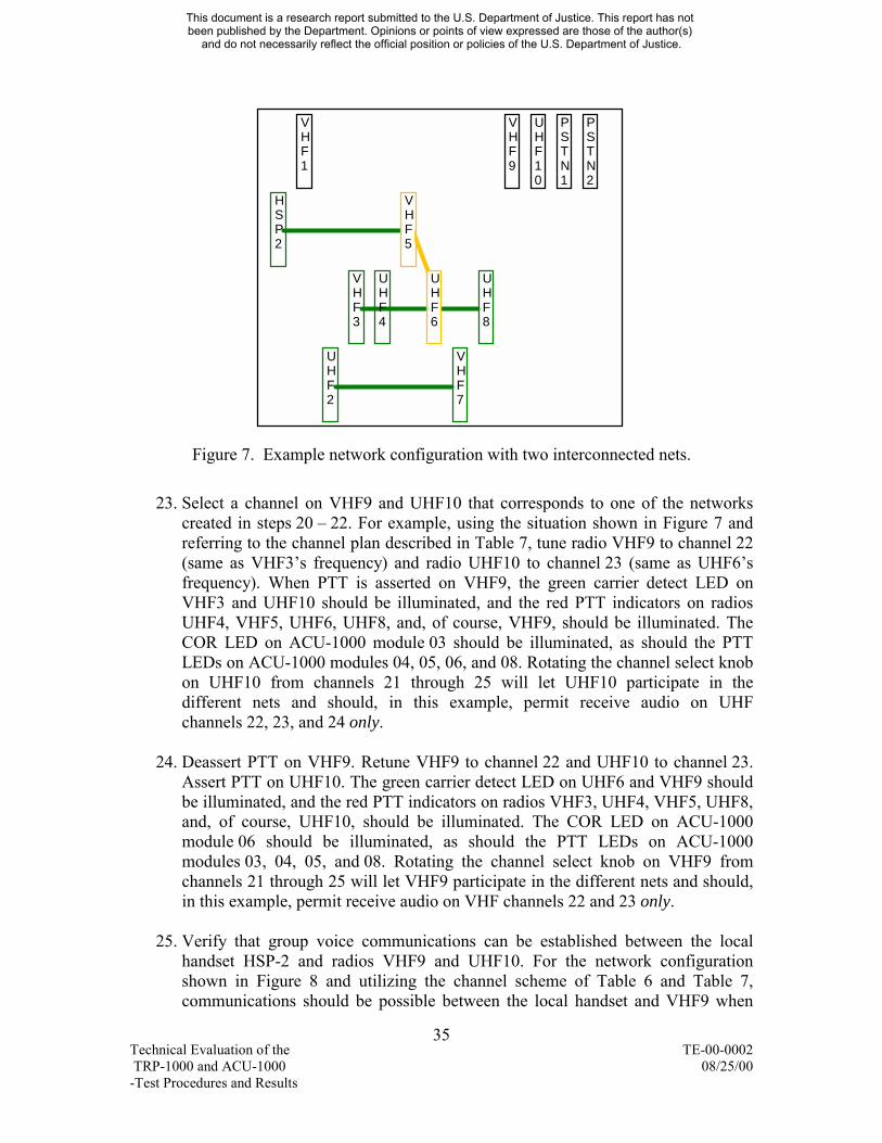
Award Number TE-00-002-01 This report has not been published by the US Department of Justice To provide better customer service NCJRS has made this Federally-funded grant final report available electronically in addition to traditional paper copies
Opinions or points of view expressed are those
of the author(s) and do not necessarily reflect the official position or policies of the US
Department of Justice
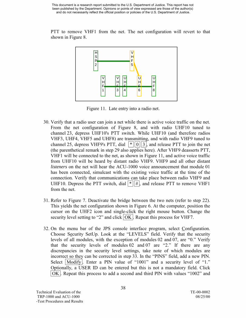
ADVANCED GENERATION OF INTEROPERABILITY FOR LAW ENFORCEMENT
A Program of the National Institute of Justice
TECHNOLOGY EVALUATION PROJECT
Technical Evaluation of the TRP-1000 and ACU-1000 -Test Procedures and Results Document No TE-00-0002-01
August 25 2000
Prepared by
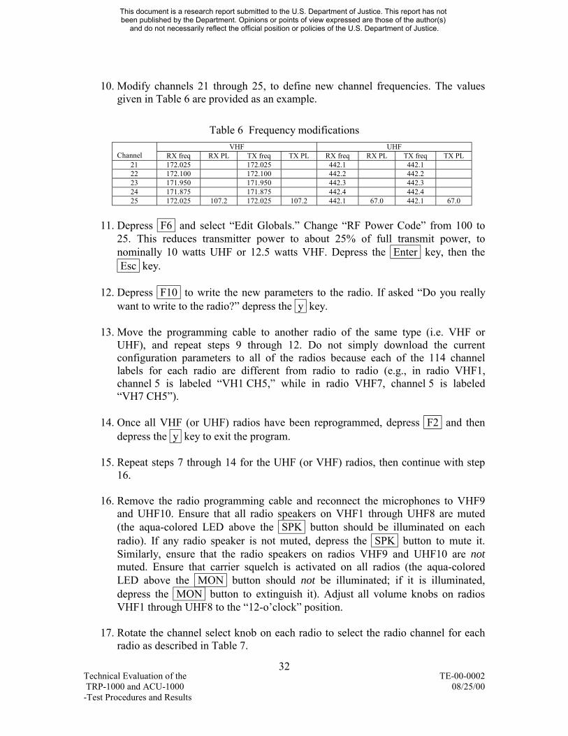
OLES Institute for Telecommunication Sciences 325 Broadway
NTIAITSP Boulder Colorado 80305
This document is a research report submitted to the US Department of Justice This report has not been published by the Department Opinions or points of view expressed are those of the author(s)
and do not necessarily reflect the official position or policies of the US Department of Justice
The AGILE Program is supported by multiple Interagency Agreements which include 1999-IJ-CX-A094 and 1000-LT-VX-A034 awarded by the US Department of Justice Office of Justice Programs National Institute of Justice Analyses of test results do not represent product approval or endorsement by the National Institute of Justice US Department of Justice the National Institute of Standards and Technology US Department of Commerce or Aspen Systems Corporation Points of view or opinions contained within this document are those of the authors and do not necessarily represent the official position of the US Department of Justice
The National Institute of Justice is a component of the Office of Justice Programs which also includes the Bureau of Justice Assistance Bureau of Justice Statistics Office of Juvenile Justice and Delinquency Prevention and Office for Victims of Crime
ii
This document is a research report submitted to the US Department of Justice This report has not been published by the Department Opinions or points of view expressed are those of the author(s)
and do not necessarily reflect the official position or policies of the US Department of Justice
Table of Contents Executive Summary 1
Equipment Performance Specifications 2 Audio Quality Performance 3 ACU-1000TRP-1000 Performance to Set-up and Create Communication Network Scenarios 3 ACU-1000TRP-1000 Unintended Electromagnetic Interference (EMI) Performance 4 Summary 4
1 Introduction 511 The NIJ and its AGILE Program 5 12 The AGILE Technology Evaluation Project 6 13 Scope of this Document 6
2 Background 73 General Evaluation Approach ndash Laboratory Testing 8
31 Measurement of Actual ACU-1000 Performance Versus Manufacturerlsquos Specifications 832 Measurement of ACU-1000 Performance Not Specified by the Manufacturer 8 33 Analysis of Potential ACU-1000 Problem Area 9 34 Examination of TRP-1000ACU-1000 Performance Within Typical Functional Scenarios 9
51 Introduction 2952 Functional Test Approach 29 53 Functional Test Procedure 30 54 Summary of Results of Functional Evaluation 41
Bridged networks can become permanently merged 41
iii Technical Evaluation of the TE-00-0002 TRP-1000 and ACU-1000 082500 -Test Procedures and Results
This document is a research report submitted to the US Department of Justice This report has not been published by the Department Opinions or points of view expressed are those of the author(s)
and do not necessarily reflect the official position or policies of the US Department of Justice
Digital phone connection to ACU-1000 resulted in unreliable linking of ACU-1000 module connections 41 DTMF tones from some radios were incorrectly decoded or detected 42 A late entrant into a radio net would sometimes not hear active voice traffic 42 PSTN circuits can remain connected 43 Replacing DSP or PSTN modules with power still applied to the ACU-1000 controller can reconfigure radio networks 43 New configuration files can breach current security modes 43
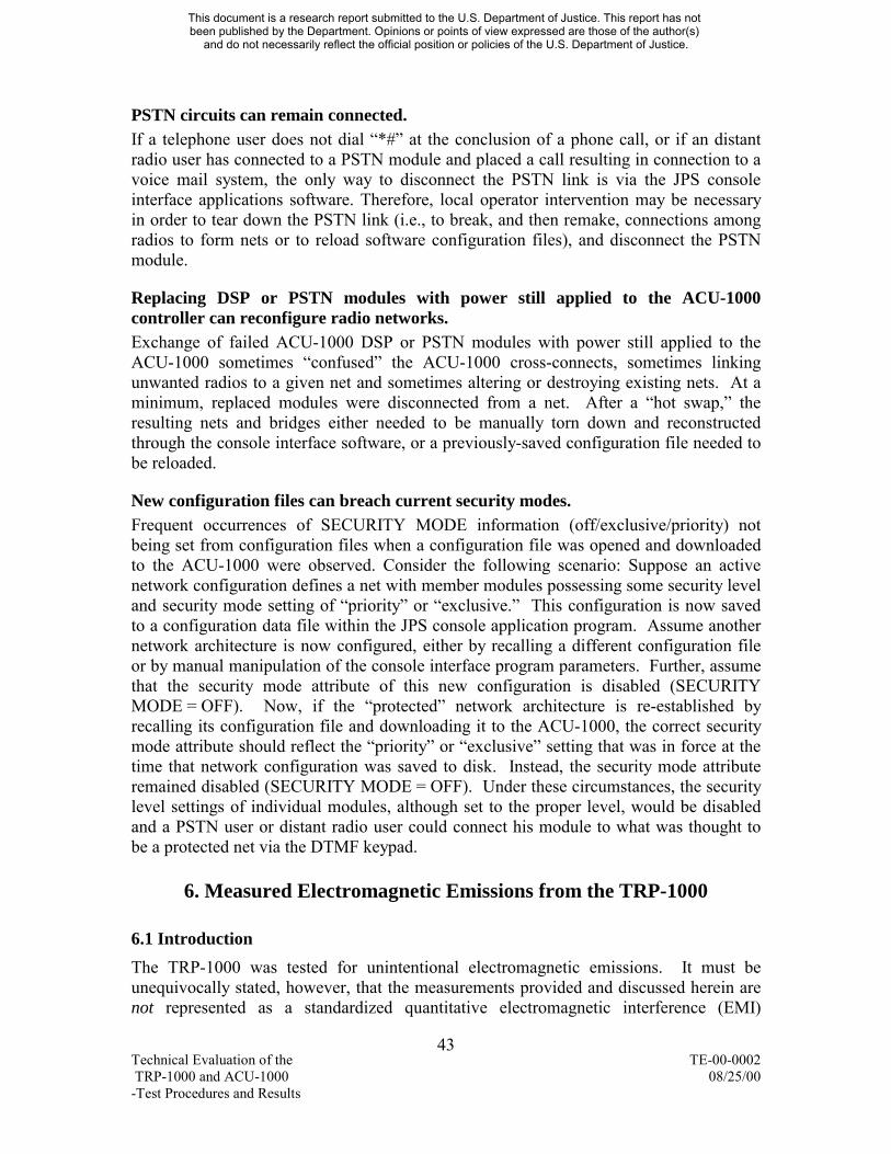
6 Measured Electromagnetic Emissions from the TRP-1000 4361 Introduction 4362 Measurements 44 63 Summary of Results 47
iv Technical Evaluation of the TE-00-0002 TRP-1000 and ACU-1000 082500 -Test Procedures and Results
This document is a research report submitted to the US Department of Justice This report has not been published by the Department Opinions or points of view expressed are those of the author(s)
and do not necessarily reflect the official position or policies of the US Department of Justice
Technical Evaluation of the TRP-1000 and ACU-1000 -Test Procedures and Results
Executive Summary The National Telecommunications and Information Administrationlsquos Institute for Telecommunication Sciences (ITS) conducted a series of tests to evaluate the functionality of the Multiple Agency Radio Interoperability Program (MARIP)1
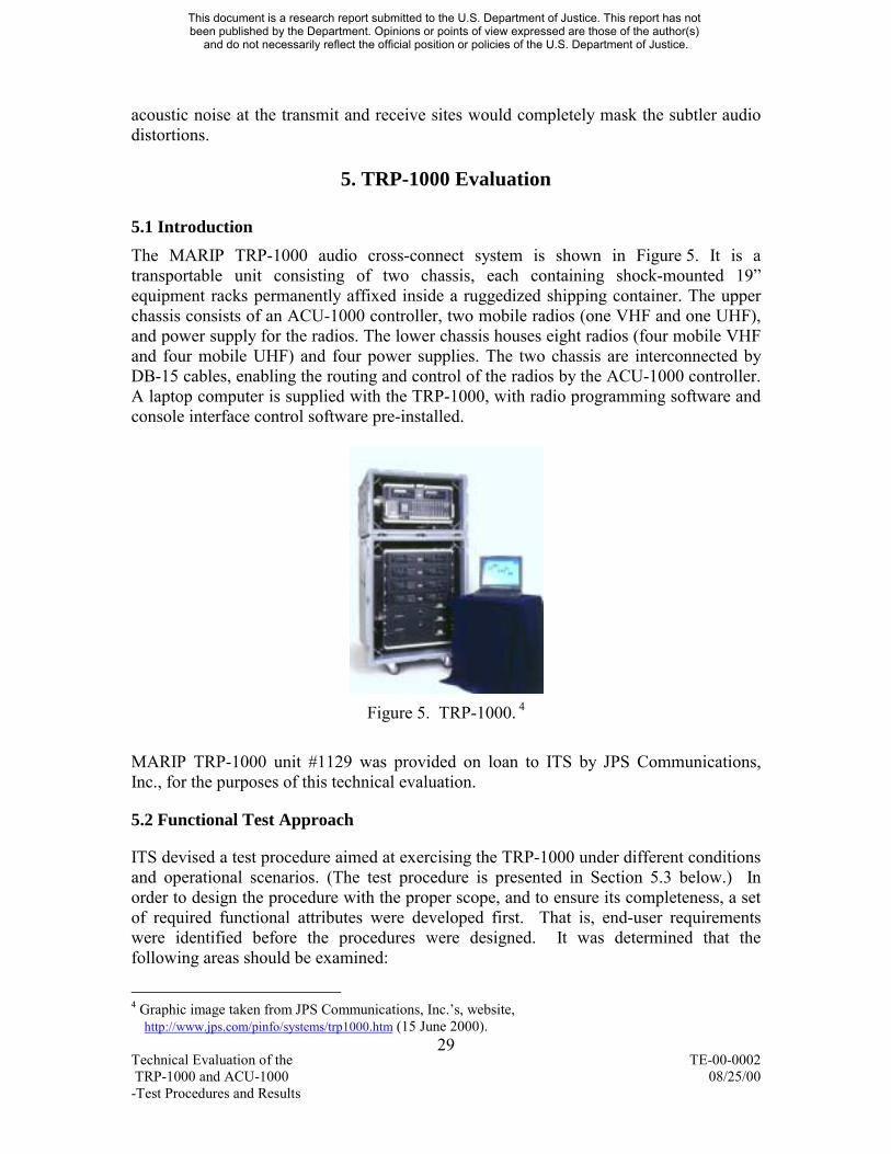
mdashTRP-1000 Transportable Intelligent Interconnect Systemldquo and its integrated ACU-1000 audio gateway switch The TRP-1000 and ACU-1000 are manufactured by JPS Communications Inc and are part of a collection of mdashcrossbandldquo technology products offered by various manufacturers The MARIP TRP-1000 comprises an ACU-1000 configured in a shock-mounted rack (surrounded by a thick plastic case) with 10 land mobile radios (LMRs) already installed as part of the system The mdashstandard radiosldquo for the MARIP TRP-1000 allow operation in the public safety bands of high-band very high frequency (VHF) 150-174 MHz and ultra high frequency (UHF) 406-470 MHz Other radios such as those operating at 800 MHz may be substituted for the packaged radios by the user The transportable TRP-1000 is promoted as allowing almost turnkey operation for many public safety situations
The ACU-1000 is designed to allow wireless communication systems to be combined at a common denominator namely the audio baseband Thus radios that operate within different parts of the radio spectrum use different modulation and access techniques or use analog versus digital encoding can interoperate This is accomplished by using the received audio from one radio system as the source audio for one or more transmitters of differing technologies That is through matrix capabilities the ACU-1000 can apply the audio to a series of radio transmitter inputs Simultaneously either one path can be created between two or more radios or several paths can be configured between sets of radios
ITS developed a series of test procedures that would determine the functionality of the ACU-1000 primarily and of the MARIP TRP-1000 secondarily The series of tests was focused to provide
1 The MARIP TRP-1000 is the designated configuration for the TRP-1000 that has been provided by the Department of Justicelsquos Office of State and Local Domestic Preparedness Support (OSLDPS) to State and local government grantees Other configurations of the TRP-1000 are available from the manufacturer based on customerslsquo requirements (for certain radio systems etc) Those configurations may exhibit some characteristics that are different from those observed with the MARIP TRP-1000 if particular feature options are used in one case and not in the other
1 Technical Evaluation of the TE-00-0002 TRP-1000 and ACU-1000 082500 -Test Procedures and Results
This document is a research report submitted to the US Department of Justice This report has not been published by the Department Opinions or points of view expressed are those of the author(s)
and do not necessarily reflect the official position or policies of the US Department of Justice
bull An evaluation of the ACU-1000lsquos modules œ manufacturerlsquos specifications versus laboratory measurements of the modules
bull Measurements of ACU-1000 characteristics that were not specified by the manufacturer
bull An evaluation of the ACU-1000TRP-1000 system audio quality performance bull A critique of the ACU-1000TRP-1000 capability to be configured to satisfy
typical scenarios that might be required for VHFUHF communications -- with local operator intervention and with members joining the communications links from telephone circuits
bull An analysis of the ACU-1000 performance when a series of critical situations occurs such as sudden loss of electrical power a need to swap a faulty module or a complex audio network is created and must be taken down
bull Finally an evaluation of anecdotal evidence about possible problem areas with the ACU-1000
Equipment Performance Specifications The series of measurements comparing actual performance against the manufacturerlsquos specifications included
bull Receive Audio Input Balance and Impedance bull Transmit Audio Output Balance and Impedance bull Receive Audio Input Level bull Transmit Audio Output Level bull Receive Audio Input Frequency Response and Transmit Audio Output Frequency
Three characteristics not specified by the manufacturer but important to the performance of the system were measuredndashcrosstalk delay and audio quality
Finally one characteristic noted by an ACU-1000 user as objectionable was analyzedndash attenuation due to local operatorlsquos speaker or handset
For all conditions and tests listed in the first group the measurements showed either minor (negative) deviations from the manufacturerlsquos specifications or were better than the specifications
For the second group the crosstalk measurement showed that none was detectable - - an important result from both a privacy and annoyance perspective The delay is a programmable feature needed to allow a radio transmitter the time to come up to operating transmit power when it is keyed with input audio The measured delays were close to manufacturerlsquos stated values and will not cause concern to most users (However when the ACU-1000 is set for the longest delay of 300 milliseconds that delay may be disconcerting to some telephone users who have the ability to talk immediately after a radio user completes a message)
2 Technical Evaluation of the TE-00-0002 TRP-1000 and ACU-1000 082500 -Test Procedures and Results
This document is a research report submitted to the US Department of Justice This report has not been published by the Department Opinions or points of view expressed are those of the author(s)
and do not necessarily reflect the official position or policies of the US Department of Justice
The objectionable characteristic of having exceptionally high attenuation of the audio signal could not be duplicated during technical evaluation testing of the MARIP TRP-1000 Subsequent analysis by other members of the AGILE team concluded that the problem was attributable to the interface between the ACU-1000 and a specific configuration of a radio model that is not included in the MARIP TRP-1000 This conclusion is consistent with the inability to duplicate the problem with the MARIP TRP-1000 configuration Additional information is available in the AGILE Technical Memorandum entitled mdashInitial Lessons Learned in Testing and Deploying the ACU-1000ldquo
Audio Quality Performance The most natural measure of the ACU-1000lsquos effect on audio quality is to evaluate a situation where no ACU-1000 is used to complete the communication link and compare the performance with the same situation where an ACU-1000 is used This was accomplished by setting up a condition where the received audio from one radio was injected directly as the audio source into the audio input of the transmitter of a second radio The audio from end-to-end was recorded for evaluation Then the ACU-1000 simply replaced the direct connection and the end-to-end audio measurements were made again
Both objective and subjective (internationally standardized) algorithms and techniques were used for evaluation Using objective methods it was observed that the 95 confidence intervals for the ACU-1000 and direct-patch cases overlapped each other ie there was no statistical difference between the two During subjective testing listeners were asked to grade the quality of the audio measurements not knowing whether they were listening to tests made with or without the ACU-1000 It was found that the audio impairments inherent in high quality VHF and UHF radio links dwarfed any audio impairments produced by the ACU-1000 That is compared to the inherent quality aberrations in a basic tandemed radio communications link the ACU-1000 impairments were very difficult for audio test listeners to detect
ACU-1000TRP-1000 Performance to Set-up and Create Communication Network Scenarios A test of the equipment was designed requiring the user to program the VHF and UHF radios in the TRP-1000 Then the user was required to prepare the ACU-1000 for communication links involving the VHF and UHF radios for typical scenarios between radio users among radio users and a local operator and among radio users telephone users and a local operator The user was to report on the ease of functional setup and usage as well as any functional impairments
The radios were easily programmed using the software provided by the radio manufacturer The ACU-1000TRP-1000 was easily configured for various scenarios using the configuration and control software supplied by the manufacturer The console operator could create networks using the graphical interfaces provided on the laptop
3 Technical Evaluation of the TE-00-0002 TRP-1000 and ACU-1000 082500 -Test Procedures and Results
This document is a research report submitted to the US Department of Justice This report has not been published by the Department Opinions or points of view expressed are those of the author(s)
and do not necessarily reflect the official position or policies of the US Department of Justice
computer However some undesirable situations resulted when certain conditions were made available for the radio users or the local operator
bull Two or more separate radio networks can be bridged for common communications and later uncoupled but some options available to the users can permanently bridge the networks together
bull Several options with a telephone connection result in conditions that can only be remedied by a console operation of the interface applications software
bull A requirement to replace a faulty module while the remaining ACU-1000 modules stay in operation can result in unwanted radios in a network or other radios being removed from a network Both situations require a console operator to break and then remake connections among radios to form nets or reload software configuration files
bull Recalling data configuration files to establish pre-defined radio networks could result in the SECURITY MODE settings of ldquoprotectedrdquo radio networks not being recognized by the ACU-1000 enabling a telephone user or radio user to enter a protected network through the userrsquos DTMF keypad
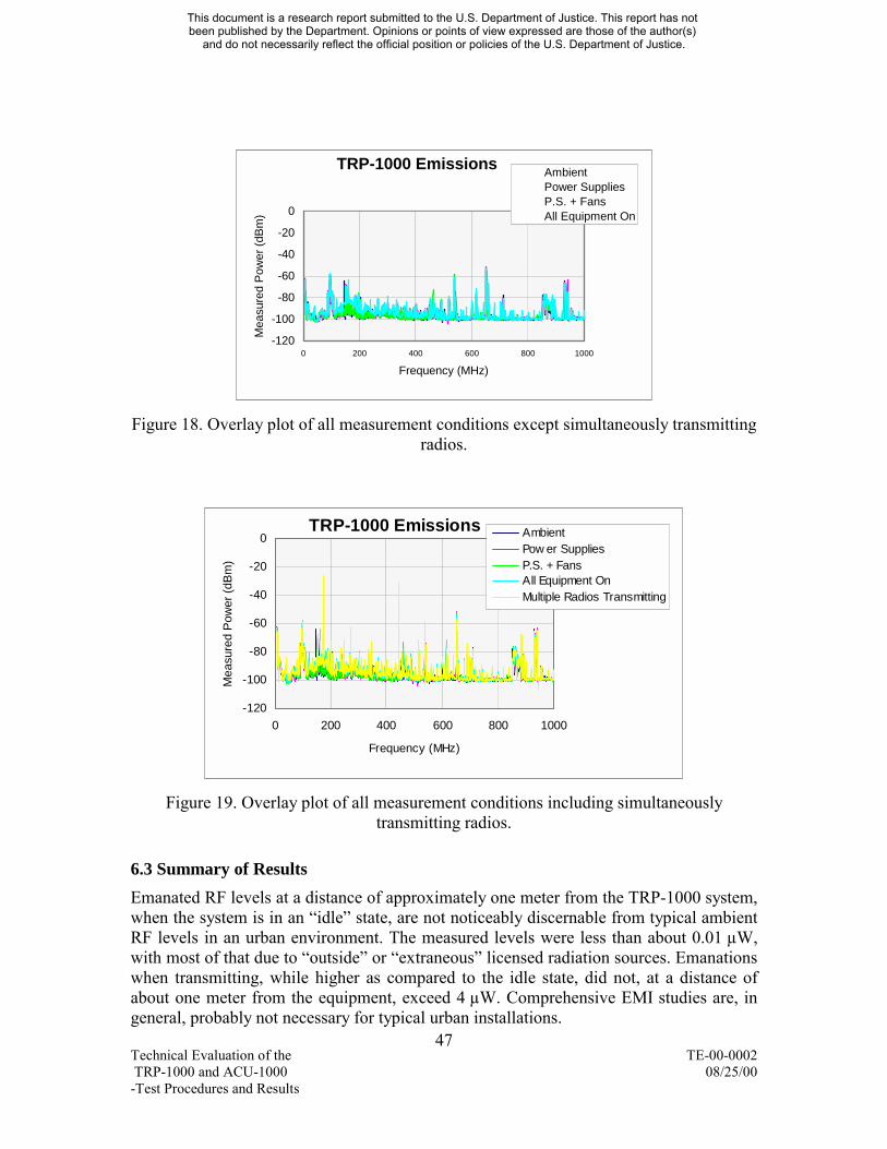
ACU-1000TRP-1000 Unintended Electromagnetic Interference (EMI) Performance Emanated radio frequency (RF) levels at a distance of approximately one meter from the TRP-1000 system when the system is in an mdashidleldquo state are not noticeably discernable from typical ambient RF levels in an urban environment
Summary The ACU-1000 contained within the MARIP TRP-1000 met the manufacturerlsquos electrical performance specifications did not impair the audio quality of the voice communications (beyond the impairments already encountered due to the radios themselves) and was easy to configure and operate However if distant radio users are allowed to remotely configure network configurations as opposed to a local operator there is a possibility of creating undesirable network configurations
4 Technical Evaluation of the TE-00-0002 TRP-1000 and ACU-1000 082500 -Test Procedures and Results
This document is a research report submitted to the US Department of Justice This report has not been published by the Department Opinions or points of view expressed are those of the author(s)
and do not necessarily reflect the official position or policies of the US Department of Justice
1 Introduction Law Enforcement work requires effective coordination communication and sharing of information with numerous criminal justice and public safety agencies Thousands of incidents that require mutual aid and coordinated response happen each and every day High-profile incidents such as bombings or plane crashes test the ability of public safety service organizations to mount well-coordinated responses In an era where technology can bring news current events and entertainment to the farthest reaches of the world many police officers firefighters and emergency medical service personnel cannot communicate with each other during routine operations or major emergencies such as the Oklahoma City Bombing Voice communication is not the only issue Advances in technology have placed an increased dependence on the sharing of data images and now even video New technologies are promoting the convergence of information and communication systems with the result that mobile units are increasingly viewed as wireless nodes within information networks Interoperability the ability of two or more organizations to communicate and share information (voice data images and video) has been brought to the forefront as a key issue for our nationlsquos public safety agencies
To illustrate this point one need only look at the existing environment of the public safety community There are more than 17000 law enforcement agencies in the United States Approximately 95 of these agencies employ fewer than 100 sworn officers Additionally over 35000 fire and emergency medical agencies exist across the nation Due to the fragmented nature of this community most public safety communications systems are stovepipe systems that do not facilitate interoperability Additionally public safety radio frequencies are distributed across four isolated frequency bands from low band VHF (25-50 MHZ) to 800 MHz (806-869 MHz) with no universally available or affordable radio able to operate across the entire range
The convergence of information and communication technologies begs a singular approach to bridge the gaps in interoperability By focusing on enabling technologies and open standards for interoperability an NIJ program provides this needed link
11 NIJ and its AGILE Program As the Department of Justices science and technology arm for State and local agencies the National Institute of Justice (NIJ) has been addressing interoperability technology issues for a number of years This is because the Law Enforcement and Corrections Technology Advisory Council (LECTAC) which provides advice and guidance to NIJ and its National Law Enforcement and Corrections Technology Centers (NLECTC) has consistently identified information sharing and communications interoperability as top priorities (LECTAC consists of representatives of state and local law enforcement and corrections practitioners) It is natural then that the goal of NIJlsquos Advanced Generation of Interoperability for Law Enforcement (AGILE) program is to assist the state and local criminal justice and public safety communities in achieving their interoperability technology needs
5 Technical Evaluation of the TE-00-0002 TRP-1000 and ACU-1000 082500 -Test Procedures and Results
This document is a research report submitted to the US Department of Justice This report has not been published by the Department Opinions or points of view expressed are those of the author(s)
and do not necessarily reflect the official position or policies of the US Department of Justice
AGILE is a comprehensive program that addresses interoperability technology issues on several fronts while leveraging many other related efforts in a complementary manner For example NIJ is working closely with the Administrations National Partnership for Reinventing Government (NPRG) initiatives specifically the Office of Justice Programs (OJP) Information Technology Executive Council Integration Initiative which supports the Global Criminal Justice Information Network (GCJIN) and the Public Safety Wireless Network (PSWN) The OJP Executive Council has tasked NIJ with being the technical arm for its Integration Initiative As such NIJ through its AGILE Program is leading the development of wireless telecommunications and information technology standards profiles and guidelines for information sharing to facilitate interoperability at State local and Federal levels
12 The AGILE Technology Evaluation Project The Technology Evaluation Project of the AGILE Program is focused on assessing the applicability of currently available and evolving capabilities to satisfy the interoperability requirements of users in criminal justice and public safety agencies In order to accomplish this products and services are evaluated to determine if they are both cost-efficient and effective in meeting userslsquo needs and are consistent with the tenets of the long-term standardization approach developed by AGILE for nationwide interoperability
Evaluation comprises classic techniques including observation analysis demonstration and testing In many cases products or services may be comprehensively evaluated within an independent laboratory or other closed environment For other products or services however a more extensive approach may be in order to determine the ramifications of placing those products or services in an agency conducting actual job functions To facilitate the demonstrations and testing of selected products or services of this type an operational test bed (OTB) was established at the Alexandria (Virginia) Police Department (APD) The OTB is working with APD and other agencies in the region to assess the operational impacts of technologies used to facilitate interoperability In addition focused mdashpilot projectsldquo are also being used to evaluate solutions to specific operational requirements
While evaluation processes conducted at independent laboratories may take weeks to complete (eg 4 to 8 weeks) evaluations within the OTB may take months (eg 6 to 12 months) since such evaluations carefully characterize the impact of the new product or service on existing operations and project how future operations may change with a permanent insertion of the technology
13 Scope of this Document This document presents the procedures for and summarizes the results of a technical evaluation testing associated with the Multiple Agency Radio Interoperability Program
6 Technical Evaluation of the TE-00-0002 TRP-1000 and ACU-1000 082500 -Test Procedures and Results
This document is a research report submitted to the US Department of Justice This report has not been published by the Department Opinions or points of view expressed are those of the author(s)
and do not necessarily reflect the official position or policies of the US Department of Justice
(MARIP)2 mdashTRP-1000 Transportable Intelligent Interconnect Systemldquo and its integrated ACU-1000 audio gateway switch The ACU-1000TRP-1000 products fall under the category of crossband technology devices that may be used by public safety organizations to perform wireless communications interoperability between dissimilar wireless systems By necessity this document is quite technical in nature
Also available from the AGILE Program is a Technical Memorandum addressing mdashInitial Lessons Learned in Testing and Deploying the ACU-1000ldquo The Technical Memorandum presents observations and suggestions on the use of the ACU-1000 and TRP-1000 based on the activities of the AGILE team In addition to the information gathered through the test and evaluation activities documented herein the Technical Memorandum contains lessons learned from experiences with ACU-1000 and TRP-1000 units that were not in a MARIP configuration The Lessons Learned document is intended for all ACU-1000TRP-1000 users and prospective users
2 Background A fundamental interoperability challenge today is wireless voice communications among agencies that have different radio systems operating on various radio frequencies The AGILE Program will ultimately address this issue through adoption of interoperability standards
While those standards are being developed however other mechanisms are needed that can address the interoperability requirements One of these is the audio gateway device (also called an audio matrix or a crossband switch) that links the disparate radio systems Not unlike a dispatcherlsquos patch panel such a device simply passes baseband (audio) signals from the receiver portion of one radio to the transmitter portion of a dissimilar radio system For example audio from the receiver function of a Very High Frequency (VHF) transceiver is passed to the transmitter circuitry of an Ultra High Frequency (UHF) transceiver One advantage that the audio gateway has over the dispatcherlsquos patch panel is that the audio gateway requires no manual intervention once it is configured The device automatically routes voice calls from one radio system to another via control signals (eg dual-tone multi-frequency [DTMF] signals) input by a radio user It also will allow a connection between radios and a telephone line or cellular phone or vice versa In addition the audio gateway has a degree of versatility that is not available via dispatcherslsquo patch panels That is the audio gateway can be configured for use in a mobile platform (eg in a van or sports utility vehicle [SUV]) and therefore can become part of an incident commanderlsquos command post The audio gateway then becomes a mobile repeater allowing the disparate radio systems to communicate in a wide geographical radius around the incident
2 The MARIP TRP-1000 is the designated configuration for the TRP-1000 that has been provided by the Department of Justicelsquos Office of State and Local Domestic Preparedness Support (OSLDPS) to State and local government grantees Other configurations of the TRP-1000 are available from the manufacturer based on customerslsquo requirements (for certain radio systems etc) Those configurations may exhibit some characteristics that are different from those observed with the MARIP TRP-1000 if particular feature options are used in one case and not in the other
7 Technical Evaluation of the TE-00-0002 TRP-1000 and ACU-1000 082500 -Test Procedures and Results
This document is a research report submitted to the US Department of Justice This report has not been published by the Department Opinions or points of view expressed are those of the author(s)
and do not necessarily reflect the official position or policies of the US Department of Justice
3 General Evaluation Approach ndash Laboratory Testing Although some audio gateway technology products may be tested in the OTB the first phase of evaluation (for all products chosen for evaluation) will typically involve laboratory testing and analysis aimed at answering two basic questions
Does the product operate and perform mdashas advertisedldquo and successfully address the interoperability problems that it was designed to confront
What possible impacts will the product have on agencies (and their users) during mdashnormalldquo and mdashstressldquo conditions In other words is the product mdashusableldquo
The subsections immediately below outline the types of tests and analysis that will be performed in order to provide meaningful data that can be used to answer the questions Where possible the device under test will be configured with recommended and optional components (eg interface modules) to determine if the use of certain components enhances or restricts usability and performance Similarly if the manufacturer offers different input power options the device will be configured where possible with alternative power supplies to compare usability and performance
Detailed test and analysis procedures for the ACU-1000 and TRP-1000 are presented in Sections 4 and 5 respectively
31 Measurement of Actual ACU-1000 Performance Versus Manufacturerrsquos Specifications This area of testing checks how well the unit performs relative to the specifications of the ACU-1000 provided by the manufacturer The following parameters will be reviewed
bull Receive Audio Input Balance and Impedance bull Transmit Audio Output Balance and Impedance bull Receive Audio Input Level bull Transmit Audio Output Level bull Receive Audio Input Frequency Response and Transmit Audio Output Frequency
32 Measurement of ACU-1000 Performance Not Specified by the Manufacturer This area of testing quantifies the performance of the ACU-1000 gateway device by evaluating the degradation (if any) it inflicts on end-to-end (radio system-to-radio system) operation The performance parameters listed below will be tested Although not specified by the manufacturer these are considered important for purposes of this evaluation and will be assessed
bull crosstalk bull delay bull audio quality
8 Technical Evaluation of the TE-00-0002 TRP-1000 and ACU-1000 082500 -Test Procedures and Results
This document is a research report submitted to the US Department of Justice This report has not been published by the Department Opinions or points of view expressed are those of the author(s)
and do not necessarily reflect the official position or policies of the US Department of Justice
33 Analysis of Potential ACU-1000 Problem Area In response to preliminary problem reports by ACU-1000 users this area of testing provides data to evaluate whether severe audio level attenuation is due to the use of the local operatorlsquos handset or speaker
34 Examination of TRP-1000ACU-1000 Performance Within Typical Functional Scenarios This area of testing is of a higher level in that it looks at system performance as a whole as typical operational events are simulated Examination includes the following elements
bull A critique of the ACU-1000TRP-1000rsquos is capability to be configured to satisfy typical scenarios that might be required for VHFUHF communications -- with local operator intervention and with members joining the communications links from telephone circuits
bull An analysis of the ACU-1000rsquos performance when a series of critical situations occurs such as sudden loss of electrical power a need to swap a faulty module or a complex audio network is created and must be taken down
4 ACU-1000 Evaluation
41 Introduction Throughout this section the ACU-1000 Installation and Operation Manual furnished with the TRP-1000 is referred to as mdashthe manualldquo The datasheet downloaded from the JPS website (wwwjpscom) on March 17 2000 is referred to as mdashthe datasheetldquo The DSP-1 module installed as the mdashnthldquo module in the ACU-1000 chassis is referred to as mdashmodule nldquo The Audio Precision Portable One Dual-Domain Audio Test Set used for this work is referred to as mdashthe audio test setldquo All connections between audio test equipment and the DSP-1 modules were made using balanced lines
All DSP-1 modules in the ACU-1000 chassis were set to hardware carrier operated relay (COR) mode and the COR polarity was set to the negative mode These two configuration choices allowed for audio paths to be established and held open regardless of the audio signal (or lack of audio signal) present simply by pulling the COR input(s) to ground on the appropriate DSP-1 module(s) To allow the work described here to proceed without periodic interruptions to the audio paths COR sampling was disabled on all DSP-1 modules
Disabling COR sampling means that the connection stays open as long as a COR signal is present on the originating caller radio With COR sampling enabled a signal on the callee radio could interrupt the caller depending on the priorities set in the DSP-1 configuration When COR sampling is enabled the called radio experiences momentary disruptions at periodic intervals The duration of these interruptions can be programmed to 10 different values between 50 ms to 500 ms inclusive The time period between these
9 Technical Evaluation of the TE-00-0002 TRP-1000 and ACU-1000 082500 -Test Procedures and Results
This document is a research report submitted to the US Department of Justice This report has not been published by the Department Opinions or points of view expressed are those of the author(s)
and do not necessarily reflect the official position or policies of the US Department of Justice
interruptions can be programmed to 10 different values between 1 second and 10 seconds inclusive When COR sampling is used both of these parameters will ideally be set to the minimum value that allows for reliable interruptions within a time window acceptable to the users These values will depend on the radios used and the users requirements Clearly the amount of audio impairment will be a strong function of these parameters and testing all relevant values of these parameters is beyond the scope of this study
Hardware COR is the preferred or best-case approach to connecting a radio to the DSP-1 modules It gives the fastest and most reliable transitions between transmit and receive but not all radios have hardware COR capabilities If the radios interfaced to the ACU-1000 do not have hardware COR capability then the use of Voice Operated Transmit (VOX) mode or Voice Modulation Recognition will be required
42 ACU-1000 DSP-1 Module Manufacturerrsquos Specifications The DSP-1 module contains many configurable hardware and software parameters Except as noted the default parameter settings applicable to the MARIP configuration were tested This section reports the test methods and the results obtained The test results are compared with the values specified by the manufacturer The significance of each result is discussed in a language that is as non-technical as possible Note that this section addresses the ACU-1000 DSP-1 Modules (and in some cases the ACU-1000 chassis) but no radios are involved
Receive Audio Input Balance and Impedance Specification given in the manual BalancedUnbalanced 600 Ω Unbalanced 47 kΩ
Specification given in the datasheet Balanced or Unbalanced 600 Ω or10 kΩ
Measurement procedure and results All DSP-1 cards provided were configured at the factory for balanced low-impedance input operation and this is the only configuration that was tested The ACU-1000 console interface software was used to connect modules 9 and 10 only and the COR input to module 9 was pulled to ground The audio test set was configured to provide a balanced 0 dBm 1-kHz tone to the input of module 9 A resistor substitution box was inserted between the audio test set output and the RXA line of the module 9 input An initial setting of 0 Ω resulted in output level of 382 dBm at the output of module 10 This resistance was increased until a 6 dB drop (to -218 dBm) in the output level was obtained The setting of the resistor substitution box under these conditions was 636 Ω This indicated that the input resistance at 1 kHz was 636 plusmn 6 Ω The same test on the input of module 10 yielded a reading of 631 plusmn 6 Ω These input resistances are only the real part of input impedances that in general are complex quantities However for these types of audio input circuits the approximation of impedance measurements by resistance measurements is an established and well-accepted procedure
Summary of measurement results Input resistances of 636 plusmn 6 Ω and 631 plusmn 6 Ω were measured for modules 9 and 10
10 Technical Evaluation of the TE-00-0002 TRP-1000 and ACU-1000 082500 -Test Procedures and Results
This document is a research report submitted to the US Department of Justice This report has not been published by the Department Opinions or points of view expressed are those of the author(s)
and do not necessarily reflect the official position or policies of the US Department of Justice
Significance of measurement results It is expected that in typical usage these minor variations of input resistance from a true 600 Ω input resistance will be of no consequence In fact most radios that one might wish to connect to a DSP-1 module will drive all resistances at or above 4 Ω equally well
Transmit Audio Output Balance and Impedance Specification given in the manual Balanced or Unbalanced 600 Ω
Specification given in the datasheet Balanced or Unbalanced 600 Ω
Measurement procedure and results The transmit audio outputs of the DSP-1 cards can be used in a balanced or unbalanced configuration by the appropriate choice of output connections The test described here is appropriate for either configuration The ACU-1000 console interface software was used to connect modules 9 and 10 only and the COR input to module 9 was pulled to ground The audio test set was configured to provide a balanced 0 dBm 1-kHz tone to the input of module 10 The level at the output of module 9 was measured with the audio test set in the high input impedance mode The measured level was 412 dBm The audio test set was then switched to the low input impedance mode effectively adding a 600 Ω resistive load to the output of module 9 The output level dropped to -193 dBm This is a drop of 605 dB and solving the resulting voltage divider equation gives an output resistance of 604 plusmn 6 Ω The same test on the output of module 10 yields an output resistance reading of 599 plusmn 6 Ω These output resistances are only the real part of output impedances that in general are complex quantities However for these types of audio output circuits the approximation of impedance measurements by resistance measurements is an established and well-accepted procedure
Summary of measurement results Output resistances of 604 plusmn 6 Ω and 599 plusmn 6 Ω were measured for modules 9 and 10
Significance of measurement results It is expected that in typical usage these minor variations of output resistance from a true 600 Ω output resistance will be of no consequence In fact most radios that one might wish to connect to a DSP-1 module could be driven equally well by all output resistances below approximately 10 kΩ
Receive Audio Input Level Specification given in the manual -26 dBm to +12 dBm programmable
Specification given in the datasheet -30 dBm to +10 dBm adjustable
Measurement procedure and results The ACU-1000 console interface software was used to connect modules 9 and 10 only and to set their input and output level modes to 0 dBm This software was also used to set the audio equalizer to the flat mode (mode 4) and to ensure that all other audio processing functions were disabled The COR input to module 9 was pulled to ground The audio test set was configured to provide a balanced 0 dBm 1-kHz tone to the input of module 9 The level of this tone at the output of
11 Technical Evaluation of the TE-00-0002 TRP-1000 and ACU-1000 082500 -Test Procedures and Results
This document is a research report submitted to the US Department of Justice This report has not been published by the Department Opinions or points of view expressed are those of the author(s)
and do not necessarily reflect the official position or policies of the US Department of Justice
module 10 was measured at 382 dBm into a high impedance (100 kΩ) load and -219 dBm into a 600 Ω load Strictly speaking in professional audio when dBm is the unit of measurement 600 Ω loads are assumed to be in place However since the radios provided by the manufacturer with the ACU-1000 (to form a TRP-1000) provide high impedance loads rather than 600 Ω loads both results are presented here The path from module 9 to module 10 does not provide unity gain even when inputs and outputs are all set to 0 dBm Instead this path provides a gain of -22 dB (since a 0 dBm input gives a -219 dBm output) when the output of module 10 is terminated with a 600 Ω load If a high-impedance load is connected to the output of module 10 this path then provides a gain of +38 dB (since a 0 dBm input gives a +382 mdashdBmldquo output) Similarly the path from module 10 to module 9 provides -19 dB gain (into a 600 Ω load) or +41 dB gain (into a high-impedance load)
The input level setting of module 9 was then adjusted to all possible modes as specified in the manual (-26 -20 -16 -12 -8 -4 0 +4 +8 and +12 dBm) and the level of the 1-kHz tone input was adjusted accordingly The level of the 1-kHz tone at the output of module 10 was measured for each mode and deviations in this level were noted The negative deviation with the largest magnitude was -056 dB and the largest positive deviation was +062 dB The same test was performed on the input of module 10 The negative deviation with the largest magnitude was -180 dB and the largest positive deviation was +092 dB This indicates that for modules 9 and 10 the DSP-1 receive audio input level modes agree with the specifications given in the manual to within plusmn18 dB
Summary of measurement results When two DSP-1 modules were connected through the ACU-1000 backplane and configured for 0 dBm input and output the path did not have unity gain When the output was terminated with a 600 Ω load the path gain was about -2 dB and when the output was terminated with a high-impedance load the path gain was about +4 dB Once this was taken into account the DSP-1 receive audio input level measured for modules 9 and 10 agreed with the specifications given in the manual to within plusmn18 dB
Significance of measurement results It is expected that the deviation from unity gain in paths through the ACU-1000 might present a minor annoyance to some technicians during installation and alignment It is expected that many technicians may never notice it The range of input and output level modes provided by the DSP-1 cards makes it easy to compensate for this non-unity gain if necessary It is expected that the range of input levels allowed by the DSP-1 module (nominally -26 to +12 dBm) is sufficiently wide to allow easy interfacing to the audio output of all radios The deviations between specified and measured input level modes are expected to be of no consequence since only approximate level matches are required and radio audio output levels are generally easily adjusted using the radio volume controls
Transmit Audio Output Level Specification given in the manual -26 to +12 dBm programmable
12 Technical Evaluation of the TE-00-0002 TRP-1000 and ACU-1000 082500 -Test Procedures and Results
This document is a research report submitted to the US Department of Justice This report has not been published by the Department Opinions or points of view expressed are those of the author(s)
and do not necessarily reflect the official position or policies of the US Department of Justice
Specification given in the datasheet -20 to +11 dBm adjustable
Measurement procedure and results The ACU-1000 console interface software was used to connect modules 9 and 10 only and to set their input and output level modes to 0 dBm This software was also used to set the audio equalizer to the flat mode (mode 4) and to ensure that all other audio processing functions were disabled The COR input to module 10 was pulled to ground The audio test set was configured to provide a balanced 0 dBm 1-kHz tone to the input of module 10 The level of this tone at the output of module 9 was measured and noted The output level setting of module 9 was then adjusted to all possible modes as specified in the manual (-26 -20 -16 -12 -8 -4 0 +4 +8 and +12 dBm) and the level of the 1-kHz tone at the module 9 output was measured After correction for the path gain described in the Receive Audio Input Level section the measured output levels agreed with specifications in the manual to within plusmn05 dB The same measurements were made on the output of module 10 All deviations from the specification in the manual were within plusmn07 dB
Summary of measurement results When two DSP-1 modules were connected through the ACU-1000 backplane and configured for 0 dBm input and output the path did not have unity gain When the output was terminated with a 600 Ω load the path gain was about -2 dB and when the output was terminated with a high-impedance load the path gain was about +4 dB Once this was taken into account the DSP-1 transmit audio output level measured for modules 9 and 10 agreed with the specifications given in the manual to within plusmn07 dB
Significance of measurement results It is expected that the deviation from unity gain in paths through the ACU-1000 may present a minor annoyance to some technicians during installation and alignment It is expected that many technicians may never notice it The range of input and output level modes provided by the DSP-1 cards makes it easy to compensate for this non-unity gain if necessary It is expected that range of output levels allowed by the DSP-1 module (nominally -26 to +12 dBm) is sufficiently wide to allow easy interfacing to the audio input of all radios The deviations between specified and measured output level modes are expected to be of no consequence since only approximate level matches are required
Receive Audio Input Frequency Response and Transmit Audio Output Frequency Response Specification given in the manual 100 Hz to 3200 Hz plusmn2 dB
Specification given in the datasheet 100 Hz to 3200 Hz plusmn2 dB
Measurement procedure and results It was decided to perform this test in a non-invasive fashion This precluded access to the ACU-1000 backplane audio busses and hence precluded separate measurements of the DSP-1 receive audio input and transmit audio output frequency responses Rather those two frequency responses were measured jointly The ACU-1000 console interface software was used to connect modules 9 and 10
13 Technical Evaluation of the TE-00-0002 TRP-1000 and ACU-1000 082500 -Test Procedures and Results
This document is a research report submitted to the US Department of Justice This report has not been published by the Department Opinions or points of view expressed are those of the author(s)
and do not necessarily reflect the official position or policies of the US Department of Justice
only and to set their input and output level modes to 0 dBm This software was also used to set the audio equalizer to the flat mode (mode 4) and to ensure that all other audio processing functions were disabled The COR input to module 9 was pulled to ground The audio test set was configured to provide a balanced 0 dBm 1-kHz tone to the input of module 9 The output of module 10 was terminated with a 600 Ω load and the level of the tone at this output was noted As the frequency of the generator was slowly swept downward from 1 kHz the level at the output of module 10 slowly and smoothly (monotonically) dropped by 181 dB at 100 Hz As the frequency of the generator was slowly swept upward the output level slowly and smoothly (monotonically) dropped by 098 dB at 3200 Hz The same measurement was performed on the path from module 10 to module 9 with very similar results Response was down by 182 dB at 100 Hz and 094 dB at 3200 Hz
The attributes discussed earlier (input and output levels and impedances) are intrinsically related to a single input or output The frequency response of a path between two modules is clearly a function of those two modules but it could potentially also be a function of the loading of the ACU-1000 backplane audio busses that connect those two modules Thus the ACU-1000 console interface software was used to connect all 10 modules for maximum loading of the audio busses This corresponds to a maximal mdashteleconferenceldquo or mdashbroadcastldquo configuration Frequency response was then measured for the path from module 9 to module 10 and the path from module 10 to module 9 In both cases the results were practically identical (plusmn002 dB) to the results reported above
Summary of measurement results When the input and output sections of modules 9 and 10 were measured together the frequency response was smooth and decreased monotonically below and above 1 kHz Relative to the 1 kHz reference response was down by approximately 18 dB at 100 Hz and approximately 1 dB at 3200 Hz This response was maintained even when all ten modules were connected together as in a conferencing or broadcast application
Significance of measurement results The frequency response measured for two concatenated input and output sections was flatter (better) than the response specified for a single input or output section It is expected that this frequency response will be completely satisfactory for typical ACU-1000 applications In addition it is expected that the measured ACU-1000 frequency response will be significantly flatter (better) than the frequency response of the radios and phone networks that will be attached to it This means that it is highly unlikely that ACU-1000 frequency response will be a limiting factor in the performance of a typical system
Receive Audio Input Distortion and Transmit Audio Output Distortion Specification given in the manual Receive Audio Input Distortion no specification given Transmit Audio Output Distortion less than 05
Specification given in the datasheet Receive Audio Input Distortion less than 02 Transmit Audio Output Distortion no specification given
14 Technical Evaluation of the TE-00-0002 TRP-1000 and ACU-1000 082500 -Test Procedures and Results
This document is a research report submitted to the US Department of Justice This report has not been published by the Department Opinions or points of view expressed are those of the author(s)
and do not necessarily reflect the official position or policies of the US Department of Justice
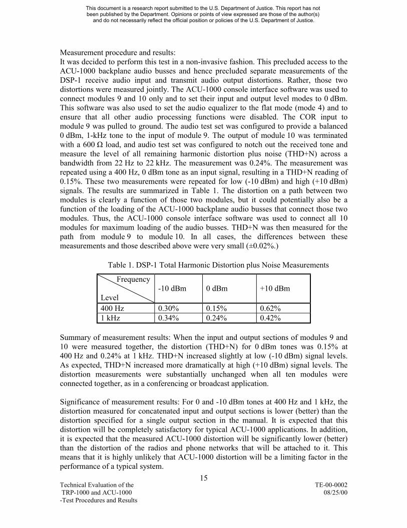
Measurement procedure and results It was decided to perform this test in a non-invasive fashion This precluded access to the ACU-1000 backplane audio busses and hence precluded separate measurements of the DSP-1 receive audio input and transmit audio output distortions Rather those two distortions were measured jointly The ACU-1000 console interface software was used to connect modules 9 and 10 only and to set their input and output level modes to 0 dBm This software was also used to set the audio equalizer to the flat mode (mode 4) and to ensure that all other audio processing functions were disabled The COR input to module 9 was pulled to ground The audio test set was configured to provide a balanced 0 dBm 1-kHz tone to the input of module 9 The output of module 10 was terminated with a 600 Ω load and audio test set was configured to notch out the received tone and measure the level of all remaining harmonic distortion plus noise (THD+N) across a bandwidth from 22 Hz to 22 kHz The measurement was 024 The measurement was repeated using a 400 Hz 0 dBm tone as an input signal resulting in a THD+N reading of 015 These two measurements were repeated for low (-10 dBm) and high (+10 dBm) signals The results are summarized in Table 1 The distortion on a path between two modules is clearly a function of those two modules but it could potentially also be a function of the loading of the ACU-1000 backplane audio busses that connect those two modules Thus the ACU-1000 console interface software was used to connect all 10 modules for maximum loading of the audio busses THD+N was then measured for the path from module 9 to module 10 In all cases the differences between these measurements and those described above were very small (plusmn002)
Table 1 DSP-1 Total Harmonic Distortion plus Noise Measurements
Frequency -10 dBm 0 dBm +10 dBm
Level 400 Hz 030 015 062 1 kHz 034 024 042
Summary of measurement results When the input and output sections of modules 9 and 10 were measured together the distortion (THD+N) for 0 dBm tones was 015 at 400 Hz and 024 at 1 kHz THD+N increased slightly at low (-10 dBm) signal levels As expected THD+N increased more dramatically at high (+10 dBm) signal levels The distortion measurements were substantially unchanged when all ten modules were connected together as in a conferencing or broadcast application
Significance of measurement results For 0 and -10 dBm tones at 400 Hz and 1 kHz the distortion measured for concatenated input and output sections is lower (better) than the distortion specified for a single output section in the manual It is expected that this distortion will be completely satisfactory for typical ACU-1000 applications In addition it is expected that the measured ACU-1000 distortion will be significantly lower (better) than the distortion of the radios and phone networks that will be attached to it This means that it is highly unlikely that ACU-1000 distortion will be a limiting factor in the performance of a typical system
15 Technical Evaluation of the TE-00-0002 TRP-1000 and ACU-1000 082500 -Test Procedures and Results
This document is a research report submitted to the US Department of Justice This report has not been published by the Department Opinions or points of view expressed are those of the author(s)
and do not necessarily reflect the official position or policies of the US Department of Justice
Transmit Audio Output Noise Floor Specification given in the manual -65 dBm
Specification given in the datasheet no specification given
Measurement procedure and results The ACU-1000 console interface software was used to disconnect all modules from the ACU-1000 audio busses and to set their input and output level modes to 0 dBm This software was also used to set the audio equalizer to the flat mode (mode 4) and to ensure that all other audio processing functions were disabled The output of module 9 was terminated with a 600 Ω load and the audio test set was used to measure the residual noise level across a bandwidth of 22 Hz to 22 kHz The measured value was -668 dBm The measurement was repeated for module 10 resulting in the same value of -668 dBm
Summary of measurement results An output noise floor of -668 dBm was measured for modules 9 and 10
Significance of measurement results The noise floor measured for modules 9 and 10 was lower (better) than the specification given in the manual by 18 dB It is expected that this noise floor will be completely satisfactory for typical ACU-1000 applications In addition it is expected that the measured ACU-1000 noise floor will be significantly lower (better) than the noise induced by the radios and phone networks that will be attached to it This means that it is highly unlikely that ACU-1000 noise will be a limiting factor in the performance of a typical system
43 Additional ACU-1000DSP-1 Measurements Measurements of crosstalk and delay were also made and an anecdote was investigated This section reports the test methods and the results obtained The significance of each result is discussed in a language that is as non-technical as possible Note that this section addresses the ACU-1000 DSP-1 Modules and the ACU-1000 chassis but no radios are involved
Crosstalk Measurement procedure and results The ACU-1000 console interface software was used to connect modules 7 and 9 (as horizontal net mdashcom1ldquo) This software was also used to connect modules 8 and 10 (as horizontal net mdashcom2ldquo) All module input and output level modes were set to 0 dBm all audio equalizers were set to the flat mode (mode 4) and all other audio processing functions were disabled The outputs of modules 9 and 10 and the input of module 8 were all terminated with 600 Ω loads The COR inputs to modules 7 and 8 were pulled to ground A tone was applied to the input of module 7 and the resulting level at the output of module 10 was measured The tone frequency was set to 500 Hz 1 2 and 3 kHz The tone level was stepped from -70 dBm to +20 dBm in 10 dB steps For all combinations of input tone frequency and level the measured level at the output of module 10 remained at -63 dBm This corresponds to a noise floor and indicates that there was no measurable crosstalk in this configuration
16 Technical Evaluation of the TE-00-0002 TRP-1000 and ACU-1000 082500 -Test Procedures and Results
This document is a research report submitted to the US Department of Justice This report has not been published by the Department Opinions or points of view expressed are those of the author(s)
and do not necessarily reflect the official position or policies of the US Department of Justice
A second crosstalk measurement was performed for a more heavily loaded configuration The ACU-1000 console interface software was used to connect modules 1 8 9 and 10 as horizontal net mdashcom1ldquo Modules 2 and 7 were connected as horizontal net mdashcom2ldquo and modules 3 4 5 and 6 were connected as horizontal net mdashcom3ldquo All module input and output level modes were set to 0 dBm all audio equalizers were set to the flat mode (mode 4) and all other audio processing functions were disabled The COR inputs to modules 1 2 and 3 were pulled to ground A tone was applied to the inputs of modules 1 and 3 and all other module inputs and outputs were terminated with 600 Ω loads The tone frequency was set to 500 Hz 1 2 and 3 kHz The tone level was stepped from -70 dBm to +20 dBm in 10 dB steps The resulting level at the output of module 7 was measured For all combinations of input tone frequency and level the measured level at the output of module 7 remained in the range of -62 to -61 dBm This corresponds to a noise floor and indicates that there was no measurable crosstalk in this configuration
Summary of measurement results In lightly loaded and heavily loaded configurations no crosstalk was measurable even for the worst-case scenario of +20 dBm 3-kHz tones
Significance of measurement results It is expected that no crosstalk will be audible in typical ACU-1000 applications This means that speech from one set of connected devices will not audibly mdashleak overldquo to another set of connected devices It is expected that this will be true even for speech at very high volume levels
Delay Measurement procedure and results The ACU-1000 console interface software was used to connect modules 9 and 10 This software was also used to set all module input and output level modes to 0 dBm all audio equalizers to the flat mode (mode 4) and to disable all other audio processing functions (It is possible that the activation of DSP-1 audio processing functions may change the audio delay) The audio delay was set to mode 0 which is specified by the manual to be 20 ms The COR input to module 9 was pulled to ground A PC with a high-quality sound card was connected to modules 9 and 10 via active unbalance-to-balanced and balanced-to-unbalanced matching amplifiers (These matching amplifiers match the unbalanced high-impedance inputs and outputs of the PC sound card to the balanced low-impedance inputs and outputs of the ACU-1000) The PC soundcard output was connected to the input of module 9 (via a matching amplifier) This allowed for the injection of test signals The PC soundcard stereo inputs were connected to the input of module 9 and the output of module 10 (via matching amplifiers) These connections allowed for synchronized digital recording of the test signals as they enter module 9 and emerge from module 10 The sample rate for all digital signals was 8000 samplessecond and the sampling resolution was 16 bitssample The ten test signals consisted of six tones (at 100 200 500 Hz 1 2 and 32 kHz) and four speech signals (two female talkers and two male talkers each saying one sentence) Delays were then estimated from the two digital recordings using the cross-correlation technique specified in the ANSI telecommunications standard T180104-1997 titled mdashMultimedia Communications Delay Synchronization and Frame Measurementldquo and ITU Recommendation P931 which has the same title
17 Technical Evaluation of the TE-00-0002 TRP-1000 and ACU-1000 082500 -Test Procedures and Results
This document is a research report submitted to the US Department of Justice This report has not been published by the Department Opinions or points of view expressed are those of the author(s)
and do not necessarily reflect the official position or policies of the US Department of Justice
The speech time delay associated with the path from module 9 to module 10 was 10625 plusmn 025 ms Cross-correlation suffers from ambiguity when applied to tones Thus the digitally recorded tones were display in a format similar to that of a two-channel digital storage oscilloscope The measured delay between the onsets of the two tones was consistent with the delay measured for speech signals However it was also noted that the path from module 9 to module 10 induced a fixed phase shift for tones at or below approximately 500 Hz This phase shift is fixed in time but it does depend on frequency It is likely that this low-frequency phase shift is produced by the transformers in the DSP-1 modules
The audio delay was set to mode 1 which is specified by the manual to be 60 ms The measurements described above were repeated The result for both tones and speech was a delay of 50375 plusmn 025 ms
The audio delay was set to mode 2 which is specified by the manual to be 100 ms The measurements described above were repeated The result for both tones and speech was a delay of 90125 plusmn 025 ms
Summary of measurement results Delays near 10 50 and 90 ms were measured for audio delay modes 0 1 and 2 respectively The manual specifies that those modes result in audio delays of 20 60 and 100 ms respectively The measurements made with speech and tones agree An additional fixed phase shift for tones at or below 500 Hz was observed
Significance of measurement results If the radios used with the ACU-1000 respond quickly enough then delay mode 0 can be used and an audio delay through the ACU-1000 near 10 ms can be attained It is expected that this delay will never be noticed If the radios do not respond quickly enough then other delay modes may be required to prevent the loss of leading syllables at the start of each transmission The longest available audio delay mode (mode 7) is specified in the manual to be 300 ms It is expected that this delay would be noticed and would cause some (but not insurmountable) impediments to the ability to converse If a 300 ms delay were required then it is expected that half-duplex (eg radio) users would be less sensitive to this delay than full-duplex (eg PSTN) users The delays measured for audio delay modes 0 1 and 2 were all approximately 10 ms lower than the delays specified in the manual This difference may inconvenience the technician who installs and adjusts a system but it is expected that this difference will not be noticed by system users
18 Technical Evaluation of the TE-00-0002 TRP-1000 and ACU-1000 082500 -Test Procedures and Results
This document is a research report submitted to the US Department of Justice This report has not been published by the Department Opinions or points of view expressed are those of the author(s)
and do not necessarily reflect the official position or policies of the US Department of Justice
Attenuation Due to Local Operatorrsquos Speaker or Handset An ACU-1000 user had noted the possibility that activation of the local operatorlsquos speaker or handset might reduce the audio levels on an active connection This possibility was investigated3
Measurement procedure and results The ACU-1000 console interface software was used to connect modules 9 and 10 only The COR input to module 9 was pulled to ground The audio test set was configured to provide a balanced 0 dBm 1-kHz tone to the input of module 9 The output of module 10 was terminated with a 600 Ω load and the level was noted The ACU-1000 console interface software was then used to add the HSP-2 module to the connection between modules 9 and 10 All different handset internal and external speaker configurations were tried The only drop in the audio level at the output of module 10 occurred when the HSP-2 was initially connected This drop was 004 dB
Summary of measurement results An audio level drop of 004 dB was measured when the HSP-2 module was connected to modules 9 and 10 All subsequent interactions with the HSP-2 module resulted in no additional audio level changes
Significance of measurement results A 004 dB decrease in a speech level is not perceptible
44 ACU-1000TRP-1000 System Audio Quality Measurements Measurement procedure and results Two sets of audio quality measurements were made One set was made for the ACU-1000TRP-1000 system and one set was made for a reference system This approach allowed the comparison of the ACU-1000TRP-1000 system audio quality with the audio quality of a relevant alternative In other words it provided an appropriate context in which to consider the ACU-1000TRP-1000 system audio quality measurements
ACU-1000TRP-1000 system applications usually involve the connection of two dissimilar communications links If an ACU-1000 or similar device were not available one would have to patch those two links together in some manual fashion It was decided to adopt this manual mdashdirect patchldquo alternative as the reference system for the audio quality measurements of the ACU-1000TRP-1000 system It was also decided to adopt a high quality VHF radio link at 172025 MHz and a high quality UHF radio link at 4421 MHz as the two dissimilar communications links Thus the audio quality measurements described here compare the audio quality of two alternate solutions for connecting the VHF link to the UHF link The ACU-1000 alternative is shown in Figure 1 and Figure 2 and the direct patch alternatives are shown in Figure 3 and
3 Initially it was not known that the report of severely attenuated audio volume originated from a user of a TRP-1000 that was not configured as a MARIP TRP-1000 Subsequent analysis by other members of the AGILE team concluded that the problem was attributable to the interface between the ACU-1000 and a specific configuration of a radio model that is not included in the MARIP TRP-1000 configuration
19 Technical Evaluation of the TE-00-0002 TRP-1000 and ACU-1000 082500 -Test Procedures and Results
This document is a research report submitted to the US Department of Justice This report has not been published by the Department Opinions or points of view expressed are those of the author(s)
and do not necessarily reflect the official position or policies of the US Department of Justice
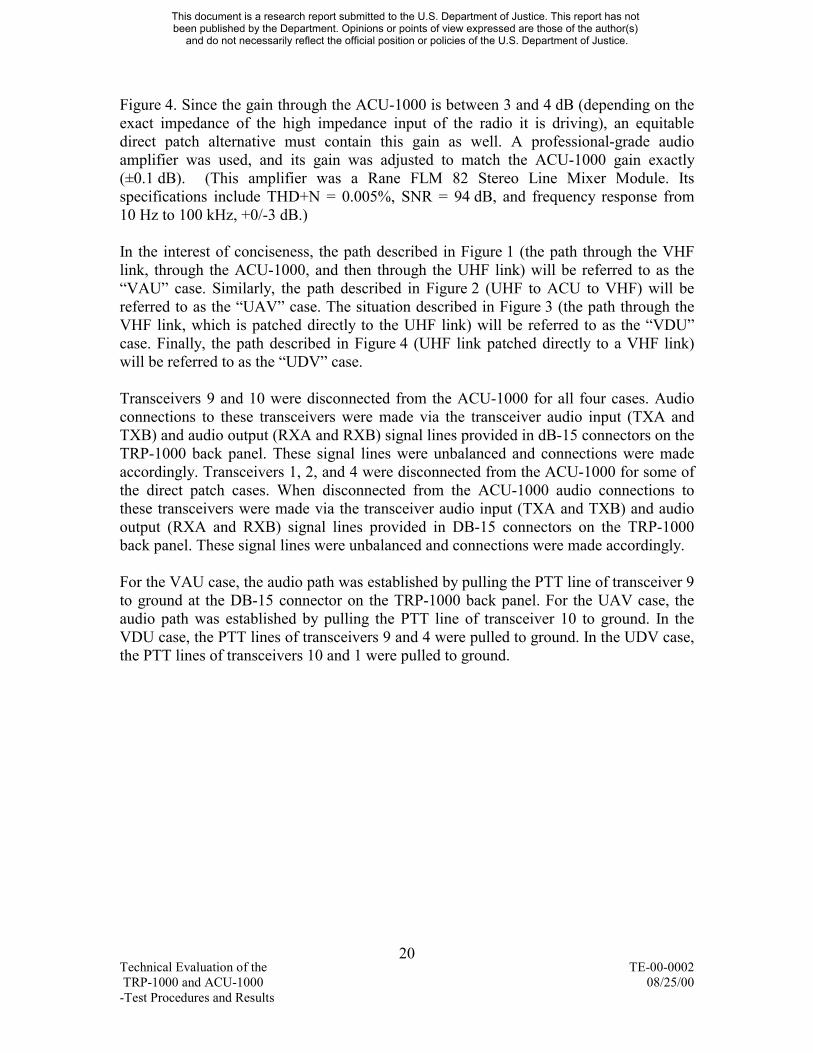
Figure 4 Since the gain through the ACU-1000 is between 3 and 4 dB (depending on the exact impedance of the high impedance input of the radio it is driving) an equitable direct patch alternative must contain this gain as well A professional-grade audio amplifier was used and its gain was adjusted to match the ACU-1000 gain exactly (plusmn01 dB) (This amplifier was a Rane FLM 82 Stereo Line Mixer Module Its specifications include THD+N = 0005 SNR = 94 dB and frequency response from 10 Hz to 100 kHz +0-3 dB)
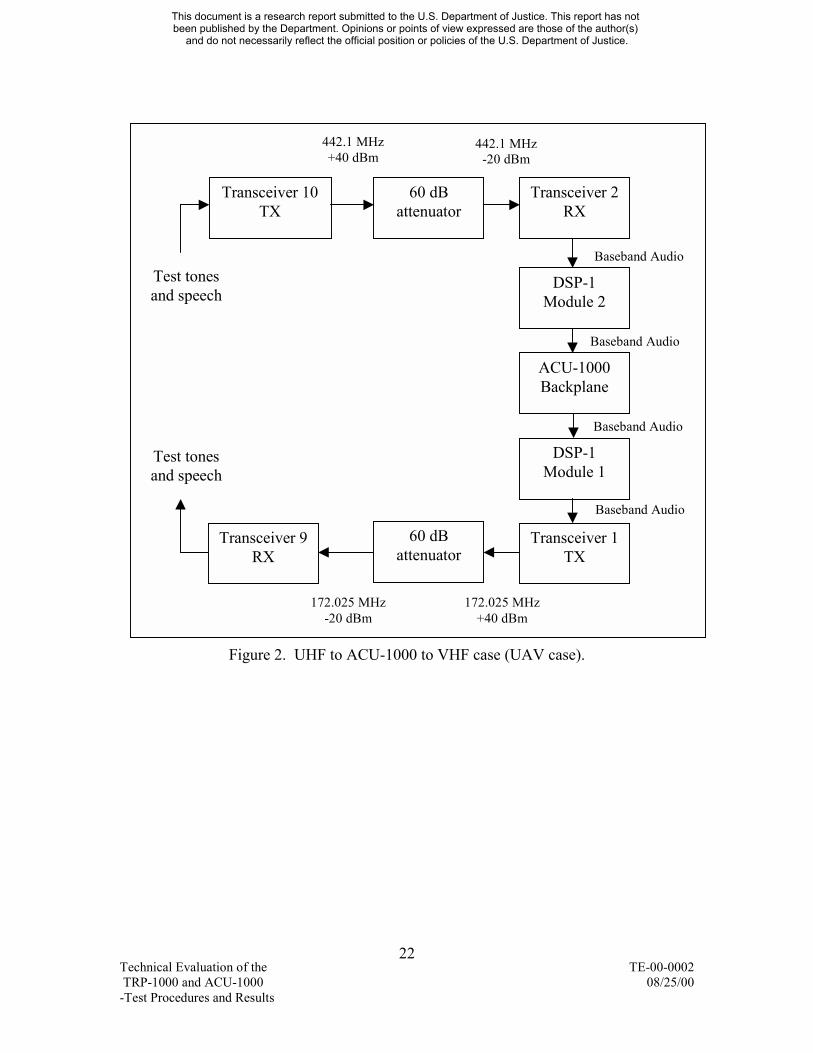
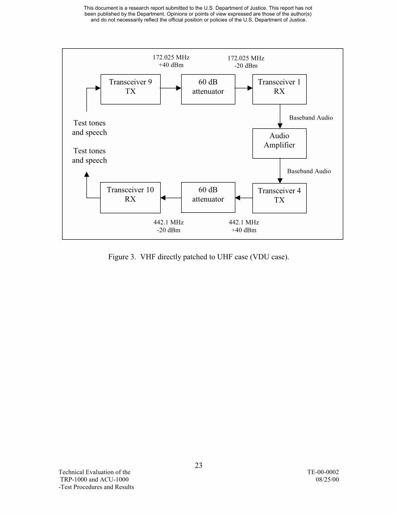
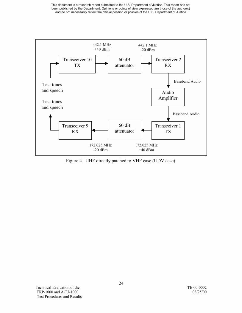
In the interest of conciseness the path described in Figure 1 (the path through the VHF link through the ACU-1000 and then through the UHF link) will be referred to as the mdashVAUldquo case Similarly the path described in Figure 2 (UHF to ACU to VHF) will be referred to as the mdashUAVldquo case The situation described in Figure 3 (the path through the VHF link which is patched directly to the UHF link) will be referred to as the mdashVDUldquo case Finally the path described in Figure 4 (UHF link patched directly to a VHF link) will be referred to as the mdashUDVldquo case
Transceivers 9 and 10 were disconnected from the ACU-1000 for all four cases Audio connections to these transceivers were made via the transceiver audio input (TXA and TXB) and audio output (RXA and RXB) signal lines provided in dB-15 connectors on the TRP-1000 back panel These signal lines were unbalanced and connections were made accordingly Transceivers 1 2 and 4 were disconnected from the ACU-1000 for some of the direct patch cases When disconnected from the ACU-1000 audio connections to these transceivers were made via the transceiver audio input (TXA and TXB) and audio output (RXA and RXB) signal lines provided in DB-15 connectors on the TRP-1000 back panel These signal lines were unbalanced and connections were made accordingly
For the VAU case the audio path was established by pulling the PTT line of transceiver 9 to ground at the DB-15 connector on the TRP-1000 back panel For the UAV case the audio path was established by pulling the PTT line of transceiver 10 to ground In the VDU case the PTT lines of transceivers 9 and 4 were pulled to ground In the UDV case the PTT lines of transceivers 10 and 1 were pulled to ground
20 Technical Evaluation of the TE-00-0002 TRP-1000 and ACU-1000 082500 -Test Procedures and Results
This document is a research report submitted to the US Department of Justice This report has not been published by the Department Opinions or points of view expressed are those of the author(s)
and do not necessarily reflect the official position or policies of the US Department of Justice
172025 MHz 172025 MHz
T T-
This document is a research report submitted to the US Department of Justice This report has not been published by the Department Opinions or points of view expressed are those of the author(s)
and do not necessarily reflect the official position or policies of the US Department of Justice
+40 dBm -20 dBm
Baseband Audio
Transceiver 1 RX
Transceiver 9 TX
60 dB attenuator
Test tones and speech
DSP-1 Module 1
Baseband Audio
ACU-1000 Backplane
Baseband Audio
Test tones and speech
DSP-1 Module 4
Baseband Audio
60 dB attenuator
Transceiver 4 TX
Transceiver 10 RX
4421 MHz 4421 MHz-20 dBm +40 dBm
Figure 1 VHF to ACU-1000 to UHF case (VAU case)
21 echnical Evaluation of the TE-00-0002 RP-1000 and ACU-1000 082500
Test Procedures and Results
4421 MHz 4421 MHz
Te TR-T
This document is a research report submitted to the US Department of Justice This report has not been published by the Department Opinions or points of view expressed are those of the author(s)
and do not necessarily reflect the official position or policies of the US Department of Justice
+40 dBm -20 dBm
Baseband Audio
Transceiver 2 RX
Transceiver 10 TX
60 dB attenuator
Test tones and speech
DSP-1 Module 2
Baseband Audio
ACU-1000 Backplane
Baseband Audio
Test tones and speech
DSP-1 Module 1
Baseband Audio
60 dB attenuator
Transceiver 1 TX
Transceiver 9 RX
172025 MHz 172025 MHz-20 dBm +40 dBm
Figure 2 UHF to ACU-1000 to VHF case (UAV case)
22 chnical Evaluation of the TE-00-0002 P-1000 and ACU-1000 082500
est Procedures and Results
172025 MHz 172025 MHz
T T-T
This document is a research report submitted to the US Department of Justice This report has not been published by the Department Opinions or points of view expressed are those of the author(s)
and do not necessarily reflect the official position or policies of the US Department of Justice
Baseband Audio
Baseband Audio
-20 dBm
Transceiver 1 RX
+40 dBm
Transceiver 9 TX
60 dB attenuator
Test tones and speech Audio
Amplifier
4421 MHz +40 dBm
4421 MHz -20 dBm
Transceiver 10 RX
60 dB attenuator
Test tones and speech
Transceiver 4 TX
Figure 3 VHF directly patched to UHF case (VDU case)
23 echnical Evaluation of the TE-00-0002 RP-1000 and ACU-1000 082500 est Procedures and Results
4421 MHz 4421 MHz
T -
This document is a research report submitted to the US Department of Justice This report has not been published by the Department Opinions or points of view expressed are those of the author(s)
and do not necessarily reflect the official position or policies of the US Department of Justice
Baseband Audio
Baseband Audio
-20 dBm
Transceiver 2 RX
+40 dBm
Transceiver 10 TX
60 dB attenuator
Test tones and speech Audio
Amplifier
172025 MHz +40 dBm
172025 MHz -20 dBm
Transceiver 9 RX
60 dB attenuator
Test tones and speech
Transceiver 1 TX
Figure 4 UHF directly patched to VHF case (UDV case)
24 echnical Evaluation of the TE-00-0002
TRP-1000 and ACU-1000 082500 Test Procedures and Results
The ACU-1000 console interface software was used to connect the appropriate modules (1 and 2 or 1 and 4) This software was also used to set all module 1 2 and 4 input and output level modes to 0 dBm and audio equalizers to mode 0 (described as mdashreservedldquo in the manual) All other audio processing functions were disabled These are the factory default settings for this TRP-1000 system To prevent periodic interruptions to the audio paths COR sampling was disabled
As indicated in Figure 1 through Figure 4 both tones (from the audio test set) and digitally recorded speech (from a PC with a soundcard) were used in the work described here The PC with soundcard configuration was the same as that described in the section on delay measurements but with unbalanced connections to the appropriate transceivers This PC can inject digital speech recordings into a system under test and can simultaneously record the speech input to and output from the device under test These digital recordings used a sample rate of 8000 samplessecond and a sampling resolution of 16 bitssample The recorded speech was injected at a level that resulted in transmitter deviations of 15 to 25 kHz This range of deviations is typical of the transmitter deviations measured when talking into the handheld microphones provided with the radios Transmitter deviation was measured with a Motorola R-2670 FDMA Digital Communications System Analyzer
Each of the transceivers was programmed to transmit in low power mode resulting in a nominal transmit power of +40 dBm (10 watts) The antenna connectors of the two transceivers forming a link were connected through a pair of 30 dB attenuators resulting in a total attenuation of 60 dB and an approximate received signal strength of -20 dBm This high level of received signal strength provided full quieting without overloading the receiverslsquo front-ends
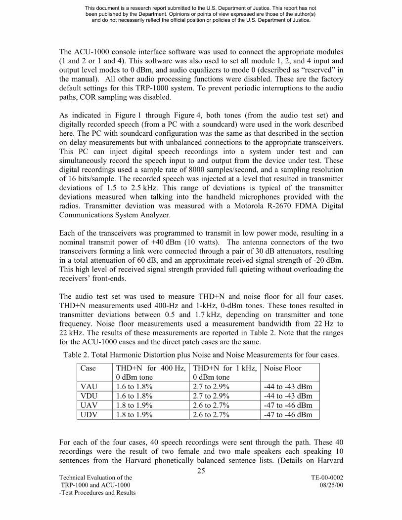
The audio test set was used to measure THD+N and noise floor for all four cases THD+N measurements used 400-Hz and 1-kHz 0-dBm tones These tones resulted in transmitter deviations between 05 and 17 kHz depending on transmitter and tone frequency Noise floor measurements used a measurement bandwidth from 22 Hz to 22 kHz The results of these measurements are reported in Table 2 Note that the ranges for the ACU-1000 cases and the direct patch cases are the same
Table 2 Total Harmonic Distortion plus Noise and Noise Measurements for four cases
Case THD+N for 400 Hz 0 dBm tone
THD+N for 1 kHz 0 dBm tone
Noise Floor
VAU 16 to 18 27 to 29 -44 to -43 dBm VDU 16 to 18 27 to 29 -44 to -43 dBm UAV 18 to 19 26 to 27 -47 to -46 dBm UDV 18 to 19 26 to 27 -47 to -46 dBm
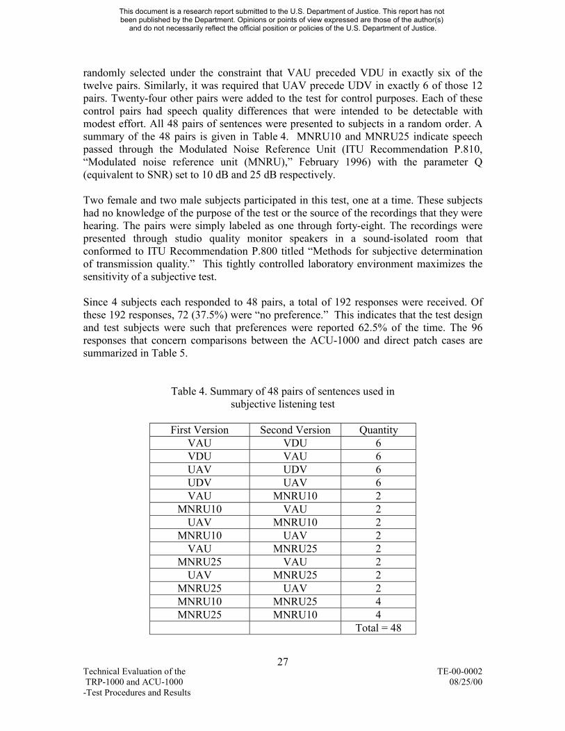
For each of the four cases 40 speech recordings were sent through the path These 40 recordings were the result of two female and two male speakers each speaking 10 sentences from the Harvard phonetically balanced sentence lists (Details on Harvard
25 Technical Evaluation of the TE-00-0002 TRP-1000 and ACU-1000 082500 -Test Procedures and Results
This document is a research report submitted to the US Department of Justice This report has not been published by the Department Opinions or points of view expressed are those of the author(s)
and do not necessarily reflect the official position or policies of the US Department of Justice
phonetically balanced sentence lists can be found in mdashIEEE Recommended Practice for Speech Quality Measurementsldquo IEEE Transactions on Audio and Electroacoustics September 1969) The quality of the resulting speech recordings was measured both objectively and subjectively
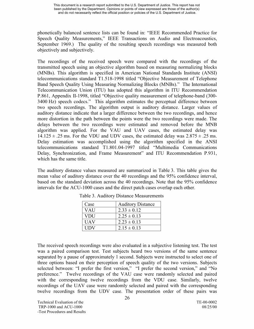
The recordings of the received speech were compared with the recordings of the transmitted speech using an objective algorithm based on measuring normalizing blocks (MNBs) This algorithm is specified in American National Standards Institute (ANSI) telecommunications standard T1518-1998 titled mdashObjective Measurement of Telephone Band Speech Quality Using Measuring Normalizing Blocks (MNBs)ldquo The International Telecommunication Union (ITU) has adopted this algorithm in ITU Recommendation P861 Appendix II-1998 titled mdashObjective quality measurement of telephone-band (300-3400 Hz) speech codecsldquo This algorithm estimates the perceptual difference between two speech recordings The algorithm output is auditory distance Larger values of auditory distance indicate that a larger difference between the two recordings and hence more distortion in the path between the points were the two recordings were made The delays between the two recordings were estimated and removed before the MNB algorithm was applied For the VAU and UAV cases the estimated delay was 14125 plusmn 25 ms For the VDU and UDV cases the estimated delay was 2875 plusmn 25 ms Delay estimation was accomplished using the algorithm specified in the ANSI telecommunications standard T180104-1997 titled mdashMultimedia Communications Delay Synchronization and Frame Measurementldquo and ITU Recommendation P931 which has the same title
The auditory distance values measured are summarized in Table 3 This table gives the mean value of auditory distance over the 40 recordings and the 95 confidence interval based on the standard deviation across the 40 recordings Note that the 95 confidence intervals for the ACU-1000 cases and the direct patch cases overlap each other
The received speech recordings were also evaluated in a subjective listening test The test was a paired comparison test Test subjects heard two versions of the same sentence separated by a pause of approximately 1 second Subjects were instructed to select one of three options based on their perception of speech quality of the two versions Subjects selected between mdashI prefer the first versionldquo mdashI prefer the second versionldquo and mdashNo preferenceldquo Twelve recordings of the VAU case were randomly selected and paired with the corresponding twelve recordings from the VDU case Similarly twelve recordings of the UAV case were randomly selected and paired with the corresponding twelve recordings from the UDV case The presentation order of these pairs was
26 Technical Evaluation of the TE-00-0002 TRP-1000 and ACU-1000 082500 -Test Procedures and Results
This document is a research report submitted to the US Department of Justice This report has not been published by the Department Opinions or points of view expressed are those of the author(s)
and do not necessarily reflect the official position or policies of the US Department of Justice
randomly selected under the constraint that VAU preceded VDU in exactly six of the twelve pairs Similarly it was required that UAV precede UDV in exactly 6 of those 12 pairs Twenty-four other pairs were added to the test for control purposes Each of these control pairs had speech quality differences that were intended to be detectable with modest effort All 48 pairs of sentences were presented to subjects in a random order A summary of the 48 pairs is given in Table 4 MNRU10 and MNRU25 indicate speech passed through the Modulated Noise Reference Unit (ITU Recommendation P810 mdashModulated noise reference unit (MNRU)ldquo February 1996) with the parameter Q (equivalent to SNR) set to 10 dB and 25 dB respectively
Two female and two male subjects participated in this test one at a time These subjects had no knowledge of the purpose of the test or the source of the recordings that they were hearing The pairs were simply labeled as one through forty-eight The recordings were presented through studio quality monitor speakers in a sound-isolated room that conformed to ITU Recommendation P800 titled mdashMethods for subjective determination of transmission qualityldquo This tightly controlled laboratory environment maximizes the sensitivity of a subjective test
Since 4 subjects each responded to 48 pairs a total of 192 responses were received Of these 192 responses 72 (375) were mdashno preferenceldquo This indicates that the test design and test subjects were such that preferences were reported 625 of the time The 96 responses that concern comparisons between the ACU-1000 and direct patch cases are summarized in Table 5
Table 4 Summary of 48 pairs of sentences used in subjective listening test
First Version Second Version Quantity VAU VDU 6 VDU VAU 6 UAV UDV 6 UDV UAV 6 VAU MNRU10 2
MNRU10 VAU 2 UAV MNRU10 2
MNRU10 UAV 2 VAU MNRU25 2
MNRU25 VAU 2 UAV MNRU25 2
MNRU25 UAV 2 MNRU10 MNRU25 4 MNRU25 MNRU10 4
Total = 48
27 Technical Evaluation of the TE-00-0002 TRP-1000 and ACU-1000 082500 -Test Procedures and Results
This document is a research report submitted to the US Department of Justice This report has not been published by the Department Opinions or points of view expressed are those of the author(s)
and do not necessarily reflect the official position or policies of the US Department of Justice
Table 5 Summary of subjective test responses
Preference for ACU-1000
No Preference Preference for Direct Patch
VAU vs VDU 4 35 9 UAV vs UDV 2 34 12 Total Responses 6 69 21
The responses for the VHF-to-UHF cases and the UHF-to-VHF cases are similar When combined we find that 72 (69 out of 96) of the responses indicate no preference between the two cases In addition 22 of the responses indicate a preference for the direct patch and 6 of the responses indicate a preference for the ACU-1000 These results indicate that in the majority of the cases test subjects have no preference between the ACU-1000 audio quality and the direct patch audio quality However in the minority of cases where preferences are expressed they seem to run in favor of the direct patch audio quality over the ACU-1000 audio quality This would indicate that that there may be subtle but sometimes-detectible differences between ACU-1000 audio quality and the direct patch audio quality It is important to note that this was a highly controlled laboratory test designed for maximum sensitivity In typical ACU-1000TRP-1000 applications it is expected that background noises at both the transmitting and receiving sites would tend to mask the more subtle differences between the ACU-1000 and direct patch cases Thus it is expected that if this test were repeated in the field or with typical levels of acoustic background noise any preference trend would be greatly reduced
Summary of measurement results Audio quality measurements were made for a pair of high quality radio links connected by the ACU-1000 and for that same pair of radio links connected by a direct patch THD+N measurements using 400 Hz and 1-kHz tones fell into the range from 16 to 29 These measurements could not be used to distinguish the ACU-1000 cases from the direct patch cases Noise floor measurement fell into the range from -47 to -43 dBm and they also could not be used to distinguish between the ACU-1000 cases and the direct patch cases Forty recorded speech sentences were sent through these paths and a standardized objective speech quality estimation algorithm was applied to the resulting recordings The resulting values of auditory distance ranged from 215 to 233 and again these values could not be used to distinguish between the ACU-1000 cases and the direct patch cases A subjective listening test was conducted using the speech recordings and four listeners Seventy-two percent of the responses indicated that the listeners had no preference between the ACU-1000 cases and the direct patch cases Preference for the direct path cases were expressed 22 of the time
Significance of measurement results The audio impairments inherent in even high quality VHF and UHF radio links swamp out the audio impairments due to the ACU-1000 making them very difficult to detect It is expected that the same would be true for TIA-102 (Project 25) radio links analog and digital cellular telephones and PSTN connections It seems that in a minority of cases under laboratory conditions listeners are able to detect the added impairment of the ACU-1000 It is expected that this faint trend would be removed in actual field use where significant levels of background
28 Technical Evaluation of the TE-00-0002 TRP-1000 and ACU-1000 082500 -Test Procedures and Results
This document is a research report submitted to the US Department of Justice This report has not been published by the Department Opinions or points of view expressed are those of the author(s)
and do not necessarily reflect the official position or policies of the US Department of Justice
acoustic noise at the transmit and receive sites would completely mask the subtler audio distortions
5 TRP-1000 Evaluation
51 Introduction The MARIP TRP-1000 audio cross-connect system is shown in Figure 5 It is a transportable unit consisting of two chassis each containing shock-mounted 19ldquo equipment racks permanently affixed inside a ruggedized shipping container The upper chassis consists of an ACU-1000 controller two mobile radios (one VHF and one UHF) and power supply for the radios The lower chassis houses eight radios (four mobile VHF and four mobile UHF) and four power supplies The two chassis are interconnected by DB-15 cables enabling the routing and control of the radios by the ACU-1000 controller A laptop computer is supplied with the TRP-1000 with radio programming software and console interface control software pre-installed
Figure 5 TRP-1000 4
MARIP TRP-1000 unit 1129 was provided on loan to ITS by JPS Communications Inc for the purposes of this technical evaluation
52 Functional Test Approach
ITS devised a test procedure aimed at exercising the TRP-1000 under different conditions and operational scenarios (The test procedure is presented in Section 53 below) In order to design the procedure with the proper scope and to ensure its completeness a set of required functional attributes were developed first That is end-user requirements were identified before the procedures were designed It was determined that the following areas should be examined
4 Graphic image taken from JPS Communications Inclsquos website httpwwwjpscompinfosystemstrp1000htm (15 June 2000)
29 Technical Evaluation of the TE-00-0002 TRP-1000 and ACU-1000 082500 -Test Procedures and Results
This document is a research report submitted to the US Department of Justice This report has not been published by the Department Opinions or points of view expressed are those of the author(s)
and do not necessarily reflect the official position or policies of the US Department of Justice
bull Ease of installation and operational configuration of the TRP-1000 as described in the TRP-1000 and ACU-1000 operatorslsquo manuals
bull Ease of programming the supplied radios
bull Ability to easily and adequately control the operation and configuration of the TRP-1000 via the console interface software application program
bull Creationmodification of radio networks
bull Bridging5 or joining together independent radio networks and unlinking the bridge while maintaining the underlying netslsquo structures
bull Verification that radios interconnected at the TRP-1000 respond as expected ie a signal received on one radio is sensed by the ACU-1000 and push-to-talk is asserted on all other TRP-1000 radios that belong to the same radio network
bull Verification that local operator can communicate with distant radio users or cellularlandline telephone users via the ACU-1000 local handset
bull Initiationtermination of telephone calls to cellularlandline telephone users from distant radio users via the ACU-1000 and initiationtermination of radio calls by cellularlandline telephone users
bull Late entry of a radio user into a radio net
bull Security access control of radio networks eg denying routine users access to a mdashCommanderslsquo Netldquo
bull Ability to perform unit-level field maintenance by exchanging major line-item components (ie radios)
bull Ability to perform unit-level field maintenance by exchanging ACU-1000 module cards
bull Verification of system behavior in the event of AC power failure
bull Ability to configure different network configurations by saving and recalling radio network configuration definitions to and from computer data file
53 Functional Test Procedure The following steps comprise the actual functional test procedure used to assess the TRP-1000 To check the clarity of the procedure and to ensure that the actions could be replicated a technician was presented with a draft copy of the steps and asked to conduct the prescribed operations When the technician had questions he received additional
5 JPS Communications uses the term mdashvertical connectionldquo in their documentation in the same way that mdashbridgingldquo and mdashbridgeldquo are used in this report
30 Technical Evaluation of the TE-00-0002 TRP-1000 and ACU-1000 082500 -Test Procedures and Results
This document is a research report submitted to the US Department of Justice This report has not been published by the Department Opinions or points of view expressed are those of the author(s)
and do not necessarily reflect the official position or policies of the US Department of Justice
guidance from the radio systems engineer and the instructions were incorporated into the procedure At the point that the technician had no further procedural questions and the radio systems engineer was satisfied that the testing was being done properly the procedure was finalized The finalized procedure follows It is also illustrated in a video tape entitled mdashFunctional check of the TRP-1000 using the 31 March 2000 procedure developed by DOCNTIAITSP and performed by ITSP on 02 May 2000ldquo The video tape can be obtained by sending an e-mail request to askagilenlectcorg
1 Install and configure the TRP-1000 as described in the TRP-1000 and ACU-1000 operatorslsquo manuals
2 On the back side of the ACU-1000 chassis disconnect chassis interconnect cables 9 and 10 (DB-15) from the TRP-1000 This removes VHF9 and UHF106 radios from the system These radios will be used to simulate distant radio users Connect a standard microphone to UHF10 and the DTMF keypadmicrophone to VHF9 These microphones are supplied with the TRP-1000 system Radios VHF9 and UHF10 are the lower-most radios in the radio chassis located just above the front power supplies
3 Terminate all radio antenna ports into dummy loads MFJ-260C or similar All dummy loads should be in close proximity to one another to facilitate mdashover-the-airldquo propagation via RF leakage from the dummy loads
4 Connect the supplied laptop computer serial port to one of the Bendix-King radioslsquo microphone jack using the serial port cable and the radio programming cable
5 Boot up computer
6 Power up TRP-1000 system Toggle the power supply switches two in the front of the radio chassis two in the rear of the radio chassis and one in the rear of the ACU-1000 chassis to mdashonldquo Depress the AC power pushbutton on the front of the ACU-1000 to apply power to the unit Rotate all ten radio ONOFFVOL knobs clockwise to minimum volume
7 Launch Bendix-King radio programming software by double-clicking on the mdashShortcut to Emeditldquo icon on the computer screen desktop
8 Select mdashVHFldquo or mdashUHFldquo as appropriate
9 Depress F9 to read radio parameters If asked mdashDo you really want to upload data from the radioldquo depress the y key
The radios are identified left to right top to bottom as VHF1 UHF2 VHF3hellip UHF10 VHF1 and UHF2 are part of the upper ACU-1000 chassis while VHF3 œ UHF10 are installed in the lower radio chassis
31 Technical Evaluation of the TE-00-0002 TRP-1000 and ACU-1000 082500 -Test Procedures and Results
6
This document is a research report submitted to the US Department of Justice This report has not been published by the Department Opinions or points of view expressed are those of the author(s)
and do not necessarily reflect the official position or policies of the US Department of Justice
10 Modify channels 21 through 25 to define new channel frequencies The values given in Table 6 are provided as an example
11 Depress F6 and select mdashEdit Globalsldquo Change mdashRF Power Codeldquo from 100 to 25 This reduces transmitter power to about 25 of full transmit power to nominally 10 watts UHF or 125 watts VHF Depress the Enter key then the Esc key
12 Depress F10 to write the new parameters to the radio If asked mdashDo you really want to write to the radioldquo depress the y key
13 Move the programming cable to another radio of the same type (ie VHF or UHF) and repeat steps 9 through 12 Do not simply download the current configuration parameters to all of the radios because each of the 114 channel labels for each radio are different from radio to radio (eg in radio VHF1 channel 5 is labeled mdashVH1 CH5ldquo while in radio VHF7 channel 5 is labeled mdashVH7 CH5ldquo)
14 Once all VHF (or UHF) radios have been reprogrammed depress F2 and then depress the y key to exit the program
15 Repeat steps 7 through 14 for the UHF (or VHF) radios then continue with step 16
16 Remove the radio programming cable and reconnect the microphones to VHF9 and UHF10 Ensure that all radio speakers on VHF1 through UHF8 are muted (the aqua-colored LED above the SPK button should be illuminated on each radio) If any radio speaker is not muted depress the SPK button to mute it Similarly ensure that the radio speakers on radios VHF9 and UHF10 are not muted Ensure that carrier squelch is activated on all radios (the aqua-colored LED above the MON
MON button should not be illuminated if it is illuminated
depress the button to extinguish it) Adjust all volume knobs on radios VHF1 through UHF8 to the mdash12-olsquoclockldquo position
17 Rotate the channel select knob on each radio to select the radio channel for each radio as described in Table 7
32 Technical Evaluation of the TE-00-0002 TRP-1000 and ACU-1000 082500 -Test Procedures and Results
This document is a research report submitted to the US Department of Justice This report has not been published by the Department Opinions or points of view expressed are those of the author(s)
and do not necessarily reflect the official position or policies of the US Department of Justice
Table 7 Radio channels VHF Radio Channel UHF Radio Channel
18 Connect the computer serial port cable to plug P15 on the backside of the ACU-1000
19 Launch the JPS ACU-1000 console interface software by double-clicking on the mdashConsole Interface (2)ldquo icon on the computer screen desktop
20 After the computer is finished communicating with the ACU-1000 (takes about one minute) a number of icons corresponding to each of the installed ACU-1000 modules will be displayed in the computer program window7 A number of ACU-1000 cross-connects can now be created by positioning the cursor on the C+ soft key and single-clicking it with the left mouse button then moving the
cursor to one of the module icons (position the cursor over the yellow portion of the icon) and single-clicking then moving the cursor to a second module icon and single-clicking The two icons will be redrawn on the screen with a green line connecting them This indicates that these two modules are now cross-connected in the ACU-1000 Additional modules may be cross-connected to this existing network interconnection or mdashnetldquo by clicking on the C+ soft key next clicking on one of the icons belonging to the existing net and then clicking on an icon to be added to this net Separate nets may be created by repeating the procedure detailed in the second and the preceding sentences of this paragraph
21 Figure 6 shows an example multi-network configuration Modules may be removed from a network by clicking on C- soft key and then clicking on the module desired to be removed
The icons are labeled as DSP-1 DSP-2 HSP-2 PSTN-1 etc As the TRP-1000 is shipped from the factory radio VHF1 is connected to module DSP-1 radio UHF2 is connected to module DSP-2 and so forth In the figures of this test procedure showing various network interconnections the labels are VHF1 UHF2 etc to more clearly identify the radios being connected in a certain configuration as opposed to showing which modules are being interconnected
33 Technical Evaluation of the TE-00-0002 TRP-1000 and ACU-1000 082500 -Test Procedures and Results
7
This document is a research report submitted to the US Department of Justice This report has not been published by the Department Opinions or points of view expressed are those of the author(s)
and do not necessarily reflect the official position or policies of the US Department of Justice
H S P 2
V H F 1
U H F 2
V H F 3
U H F 4
V H F 5
U H F 6
V H F 7
U H F 8
V H F 9
U H F 1 0
P S T N 1
P S T N 2
Figure 6 Example network configuration
22 If desired independent nets can be linked together by single-clicking on the V+ soft key and then on any two icons one each in each of the existing nets The link between the two nets is depicted by a yellow line interconnecting the two modules selected in the previous sentence Additional nets can be linked together by repeating this process Figure 7 shows an example network configuration with two interconnected nets To remove this network link click on the V- soft key and then click on one of the module icons that has the yellow line connected to it The interconnection between the nets is removed while the underlying net configurations are retained
34 Technical Evaluation of the TE-00-0002 TRP-1000 and ACU-1000 082500 -Test Procedures and Results
This document is a research report submitted to the US Department of Justice This report has not been published by the Department Opinions or points of view expressed are those of the author(s)
and do not necessarily reflect the official position or policies of the US Department of Justice
H S P 2
V H F 1
U H F 2
V H F 3
U H F 4
V H F 5
U H F 6
V H F 7
U H F 8
V H F 9
U H F 1 0
P S T N 1
P S T N 2
Figure 7 Example network configuration with two interconnected nets
23 Select a channel on VHF9 and UHF10 that corresponds to one of the networks created in steps 20 œ 22 For example using the situation shown in Figure 7 and referring to the channel plan described in Table 7 tune radio VHF9 to channel 22 (same as VHF3lsquos frequency) and radio UHF10 to channel 23 (same as UHF6lsquos frequency) When PTT is asserted on VHF9 the green carrier detect LED on VHF3 and UHF10 should be illuminated and the red PTT indicators on radios UHF4 VHF5 UHF6 UHF8 and of course VHF9 should be illuminated The COR LED on ACU-1000 module 03 should be illuminated as should the PTT LEDs on ACU-1000 modules 04 05 06 and 08 Rotating the channel select knob on UHF10 from channels 21 through 25 will let UHF10 participate in the different nets and should in this example permit receive audio on UHF channels 22 23 and 24 only
24 Deassert PTT on VHF9 Retune VHF9 to channel 22 and UHF10 to channel 23 Assert PTT on UHF10 The green carrier detect LED on UHF6 and VHF9 should be illuminated and the red PTT indicators on radios VHF3 UHF4 VHF5 UHF8 and of course UHF10 should be illuminated The COR LED on ACU-1000 module 06 should be illuminated as should the PTT LEDs on ACU-1000 modules 03 04 05 and 08 Rotating the channel select knob on VHF9 from channels 21 through 25 will let VHF9 participate in the different nets and should in this example permit receive audio on VHF channels 22 and 23 only
25 Verify that group voice communications can be established between the local handset HSP-2 and radios VHF9 and UHF10 For the network configuration shown in Figure 8 and utilizing the channel scheme of Table 6 and Table 7 communications should be possible between the local handset and VHF9 when
35 Technical Evaluation of the TE-00-0002 TRP-1000 and ACU-1000 082500 -Test Procedures and Results
This document is a research report submitted to the US Department of Justice This report has not been published by the Department Opinions or points of view expressed are those of the author(s)
and do not necessarily reflect the official position or policies of the US Department of Justice
VHF9 is tuned to channels 22 and 23 only Communications should be possible between the local handset and UHF10 when UHF10 is tuned to channels 22 23 and 24 only
H S P 2
V H F 3
U H F 4
V H F 5
U H F 6
U H F 8
Figure 8 Example network configuration for handset functional check
26 Utilizing the same network configuration as in step 25 tune VHF9 and UHF10 to channels 22 and 23 respectively From a remote telephone dial the telephone number associated with either one of the PSTN modules Once connected dial (at the prompt) a followed by a two-digit extension The two-digit extension corresponds to the ACU-1000 module (and its associated net) that is to be joined
0For this example situation one dialing possibility is 5 The resulting net configuration is depicted in Figure 9 Verify that group voice communications is possible between the remote telephone VHF9 and UHF10 At the conclusion of the PSTN call the telephone user must dial to disconnect the PSTN module from the net
H S P 2
V H F 3
U H F 4
V H F 5
U H F 6
U H F 8
P S T N 1
Figure 9 Example network configuration for PSTN functional check
27 Connect the DTMF keypad microphone to radio VHF9 or UHF10 Depress the PTT switch and dial the PSTN access code 1 1 (for PSTN module 11) or
1 2 (for PSTN module 12) and release PTT Dialing 1 1 will give the net configuration shown in Figure 9 The PSTN module will be connected to
36 Technical Evaluation of the TE-00-0002 TRP-1000 and ACU-1000 082500 -Test Procedures and Results
This document is a research report submitted to the US Department of Justice This report has not been published by the Department Opinions or points of view expressed are those of the author(s)
and do not necessarily reflect the official position or policies of the US Department of Justice
the radio net once PTT has been deasserted Next in response to the voice prompt assert PTT dial the desired telephone number followed by and release PTT Verify that group voice communications can take place between
toradios VHF9 UHF10 and the telephone The telephone user must dial disconnect the PSTN module from the net
28 Verify that two remote telephone numbers can be joined onto a net Use the network configuration shown in Figure 8 and the channel scheme of Table 6 and Table 7 From a remote telephone dial the telephone number associated with one of the PSTN modules Once connected dial an extension (at the prompt) Again
0choose 5 The resultant net configuration is depicted in Figure 9 From the remote telephone dial the PSTN access code for the other PSTN module (either 1 1 1 2 ) This joins the second PSTN module into the net or as shown in Figure 10 After the voice prompt dial the desired telephone number of a second remote telephone followed by Verify group voice communications between the two remote telephones and the two radios At the conclusion of the communications both telephone users must dial to disconnect the PSTN modules from the net
H S P 2
V H F 3
U H F 4
V H F 5
U H F 6
U H F 8
P S T N 1
P S T N 2
Figure 10 Example network configuration for dual-PSTN module functional check
29 Verify that a radio user can join a net while the net is idle Establish the net configuration shown in Figure 8 Tune radio VHF9 to channel 25 This will enable VHF9 to communicate with VHF1 only At this point VHF1 is not connected to any net Tune radio UHF10 to channel 23 This will enable UHF10 to communicate with the net shown in Figure 8 Using the DTMF keypad
0microphone with radio VHF9 depress the PTT switch dial 3 and release PTT After VHF9 deasserts PTT VHF1 will be connected to the net as shown in
0 5Figure 11 (dialing would connect VHF1 to the underlying net of HSP-2 and VHF5 however since the two underlying nets are bridged together there is no difference in the crossband communications capability insofar asdistant users are concerned) Verify that radios VHF9 and UHF10 can communicate with each other Depress the PTT switch dial and release
37 Technical Evaluation of the TE-00-0002 TRP-1000 and ACU-1000 082500 -Test Procedures and Results
This document is a research report submitted to the US Department of Justice This report has not been published by the Department Opinions or points of view expressed are those of the author(s)
and do not necessarily reflect the official position or policies of the US Department of Justice
PTT to remove VHF1 from the net The net configuration will revert to that shown in Figure 8
H S P 2
V H F 3
U H F 4
V H F 5
U H F 6
U H F 8
V H F 1
Figure 11 Late entry into a radio net
30 Verify that a radio user can join a net while there is active voice traffic on the net From the net configuration of Figure 8 and with radio UHF10 tuned to channel 23 depress UHF10s PTT switch While UHF10 (and therefore radios VHF3 UHF4 VHF5 and UHF8) are transmitting and with radio VHF9 tuned to channel 25 depress VHF9s PTT dial 3 and release PTT to join the net 0 (the parenthetical remark in step 29 also applies here) After VHF9 deasserts PTT VHF1 will be connected to the net as shown in Figure 11 and active voice traffic from UHF10 will be heard by distant radio VHF9 VHF9 and all other distant listeners on the net will hear the ACU-1000 voice announcement that module 01 has been connected simulcast with the existing voice traffic at the time of the connection Verify that communications can take place between radio VHF9 and UHF10 Depress the PTT switch dial and release PTT to remove VHF1 from the net
31 Refer to Figure 7 Deactivate the bridge between the two nets (refer to step 22) This yields the net configuration shown in Figure 6 At the computer position the cursor on the UHF2 icon and single-click the right mouse button Change the security level setting to mdash2ldquo and click OK Repeat this process for VHF7
32 On the menu bar of the JPS console interface program select Configuration Choose Security SetUp Look at the mdashLEVELSldquo field Verify that the security levels of all modules with the exception of modules 02 and 07 are mdash0ldquo Verify that the security levels of modules 02 and 07 are mdash2ldquo If there are any discrepancies in the security level settings take note of which modules are incorrect so they can be corrected in step 33 In the mdashPINSldquo field add a new PIN Select Modify Enter a PIN value of mdash1001ldquo and a security level of mdash1ldquo Optionally a USER ID can be entered but this is not a mandatory field Click OK Repeat this process to add a second and third PIN with values mdash1002ldquo and
38 Technical Evaluation of the TE-00-0002 TRP-1000 and ACU-1000 082500 -Test Procedures and Results
This document is a research report submitted to the US Department of Justice This report has not been published by the Department Opinions or points of view expressed are those of the author(s)
and do not necessarily reflect the official position or policies of the US Department of Justice
mdash1003ldquo and security levels of mdash2ldquo and mdash3ldquo respectively Click on mdashPriorityldquo SECURITY MODE Then click OK
33 If any security levels of the modules need to be corrected repeat the process of the next to last two sentences in step 31 for the appropriate modules Then on the menubar of the JPS console interface software application under mdashFileldquo select mdashSave Asldquo Type mdashCicfg032ldquo and click Save
34 Attempt to join VHF9 with the protected (UHF2VHF7) net by linking VHF1 to the net The following process describes four attempts to join the protected net one using an invalid access ID one using a valid ID but with insufficient access privileges one with sufficient access privileges and one with access privileges exceeding that which is required With radio VHF9 tuned to channel 25 (VHF1s frequency) depress the PTT dial 2 and release the PTT At the mdashuser IDldquo 0 prompt depress PTT enter any number sequence other than the three PINs established in step 32 followed by and release PTT The ACU-1000 will respond with mdashInvalid IDldquo and deny the connection request (of VHF1 to the UHF2VHF7 net) Depress the PTT dial 0 2 and release the PTT At the mdashuser IDldquo prompt depress PTT enter 1 0 0 1 and release PTT The ACU-1000 will respond with mdashSecurity Violationldquo and deny the connection request because PIN 1001 has a lower security level access than the UHF2VHF7 net Depress the PTT dial 0
1 0 0 2 2 and release the PTT At the mdashuser IDldquo
prompt depress PTT enter and release PTT VHF1 will be added to the net because PIN 1002 has equal security level access to the UHF2VHF7 net See Figure 12 Tune UHF10 to channel 25 (UHF2s frequency) Verify that communications can be conducted between radios VHF9 and UHF10 Depress PTT dial and release PTT to remove VHF1 from the net Now depress the PTT dial 2 and release the PTT At the mdashuser IDldquo prompt depress PTT enter and release PTT VHF1 will be added to the
0
1 0 0 3 net because PIN 1003 has a higher security level access than the UHF2VHF7 net With UHF10 still tuned to channel 25 verify that communications can be conducted between radios VHF9 and UHF10 Depress PTT dial and release PTT to remove VHF1 from the net
V H F 1
U H F 2
V H F 7
Figure 12 Protected net configuration
35 Establish the network configuration shown in Figure 6 Assume equipment failure of a radio Note that whichever chassis of the TRP-1000 contains the failed radio
39 Technical Evaluation of the TE-00-0002 TRP-1000 and ACU-1000 082500 -Test Procedures and Results
This document is a research report submitted to the US Department of Justice This report has not been published by the Department Opinions or points of view expressed are those of the author(s)
and do not necessarily reflect the official position or policies of the US Department of Justice
the entire chassis must be powered off and the rear fan mounting panels removed in order to access mounting nuts on an interior bracket which must be removed before the front panel radio mounting plate can be removed in order to replace the radio Toggle the power supply switches either the two in the front and the two in the rear of the radio chassis or the one in the rear of the ACU-1000 chassis (note that even though the power supply in the ACU-1000 chassis has been turned off it only controls power to the fans and the radios AC power is still applied to the ACU-1000) to mdashoffldquo Now toggle the switch(es) back mdashonldquo Verify that the radios power up on the same channels as before and that the network configurations and security levels retain Figure 6lsquos configuration Assume failure of ACU-1000 module 06 Refer to the ACU-1000 operations manual paragraph 39 on page 3-19 Remove and reseat module 06 Clear the warning messages on the console software program Note that the new module 06 has been disconnected from the VHF3UHF4UHF6UHF8 net Refer to step 20 and reattach module 06 to the VHF3UHF4UHF6UHF8 net Repeat steps 238 and 34
36 Verify system behavior in the event of AC power failure Establish the net configuration shown in Figure 6 with the security configuration of steps 31 and 32 Simulate an AC power failure by simultaneously disconnecting the AC power cords to the computer and TRP-1000 from the electrical outlets The laptop computer should continue to function uninterrupted under its own battery power The TRP-1000 should power off Reconnect the AC power cords to the electrical outlets The TRP-1000 system reboots At the computer the console interface software will display a warning message Click OK On the menubar of the JPS console interface software application under mdashOperationsldquo select mdashGet Configuration from ACUldquo At the prompt to save the current configuration click No On the menubar under mdashConfigurationldquo select mdashSecurity SetUpldquo Note that
PIN information security mode and module security level information has been retained from the last configuration before the power failure Click OK Note that all network links have been lost This can be verified using radios VHF9 and UHF10 and noting the indications and behavior of the ACU-1000 and radios VHF1 œ UHF8
37 Verify that network configurations can be saved to and recalled from computer data files On the menubar of the JPS console interface software application under mdashFileldquo select mdashOpenldquo Select mdashMaripcicldquo At the prompt to save the current configuration click No Using radios VHF9 and UHF10 verify that all modules have been disconnected (as PTT is asserted on each channel 21 œ 25 on VHF9 and UHF10 the COR LED will illuminate on only one ACU-1000 module depending on which radio (VHF9 or UHF10) is being keyed and the channel to which it is tuned) On the menubar under mdashConfigurationldquo select mdashSecurity SetUpldquo Verify that all module security levels are mdash0ldquo that SECURITY MODE is mdashOffldquo and that there are no PIN entries Click OK Repeat the above process but opening file
Note that since the current net configuration does not bridge the HSP-2VHF5 and the VHF3UHF4UHF6UHF8 nets PTT will not be asserted on radio VHF5 during the execution of step 23
40 Technical Evaluation of the TE-00-0002 TRP-1000 and ACU-1000 082500 -Test Procedures and Results
8
This document is a research report submitted to the US Department of Justice This report has not been published by the Department Opinions or points of view expressed are those of the author(s)
and do not necessarily reflect the official position or policies of the US Department of Justice
mdashCicfg032cicldquo instead Using radios VHF9 and UHF10 verify that the network configurations of Figure 6 and the security settings defined in step 32 are as expected by repeating steps 23 (note that the parenthetical remark in step 35 applies) and 34
38 Shut down the system On the menubar of the JPS console interface software application under mdashFileldquo select mdashOpenldquo Select mdashMaripcicldquo At the prompt to save the current configuration click No The file parameters of mdashMaripcicldquo restore the TRP-1000 to its factory default state Rotate all ten radio ONOFFVOL knobs fully counter-clockwise to turn off the radios Toggle the power supply switches two in the front of the radio chassis two in the rear of the radio chassis and one in the rear of the ACU-1000 chassis to mdashoffldquo Exit the console interface program Depress the AC power pushbutton on the front of the ACU-1000 to remove power from that unit Reconnect cables 9 and 10 to P9 and P10 on the rear of the ACU-1000 chassis Under the Windowstrade Start menu select mdashShut Downhellipldquo to shut down the computer
54 Summary of Results of Functional Evaluation Generally speaking the TRP-1000 performs as advertised although several unanticipated responses were observed during the execution of the test procedure These responses were documented in a Technical Memorandum prepared by the AGILE Program team subject mdashInitial Lessons Learned in Testing and Deploying the ACU-1000ldquo Brief summaries of the more significant observations made by ITS are given in the subsections that follow Additional information regarding these items can be obtained from the Technical Memorandum
Bridged networks can become permanently merged The ACU-1000 allows two or more mdashconnectionsldquo (or links among radio systems interfaced with the ACU-1000) to be bridged using the V+ command in the console software or by a DTMF-keypad command from the field The bridge between the two nets is depicted in the console programlsquos window by a yellow line interconnecting two modules one in each of the underlying nets similarly to the situation depicted in Figure 7 When the bridge between the nets is removed the underlying net configurations are retained However if a new interface module is connected to one of the underlying nets either by a PSTN user calling in to the ACU-1000 and linking to one the nets or by a radio user linking to one of the nets using the DTMF keypad the two underlying nets were merged into one single net Removing the bridge (via the mdashV-mdash command) between the two underlying nets no longer has any effect because the two nets were merged into a single net
Digital phone connection to ACU-1000 resulted in unreliable linking of ACU-1000 module connections Module connection via DTMF keystroke sequences was observed to be unreliable for several digitally-based telephones ITS experimented with making connections to the MARIP model under factory-default module settings using a variety of telephones The
41 Technical Evaluation of the TE-00-0002 TRP-1000 and ACU-1000 082500 -Test Procedures and Results
This document is a research report submitted to the US Department of Justice This report has not been published by the Department Opinions or points of view expressed are those of the author(s)
and do not necessarily reflect the official position or policies of the US Department of Justice
phone call was initiated using one of the phone technologies listed below The incoming PSTN call interfaced to the ACU-1000 via a PSTN module occupying slot 11 ITSlsquo observations are summarized in Table 8
Table 8 TRP-1000 linking responses to DTMF-keystroke commands from various cellular and landline-based telephones
Technology Observation
TDMA cell phone (ATampT) Only connected PSTN to radio module 8 (08) and the second PSTN module 12 (12)
GSM cell phone (VoiceStream) Connected properly to all modules
Analog cellphone (Airtouch) Connected properly to all modules
Digital Meridian PBX handset Connected to all modules when call to ACU-1000 was an intra-PBX call (ie dialed the local 4-digit extension)
Digital Meridian PBX handset When placing call via the PSTN (ie dialing mdash9ldquo to place outside call then dialing full North American numbering plan telephone number) only connected to handset module 0 radio modules 3 6 7 and second PSTN module 12 (00 03 06 07 12)
Analog telephone through PBX Connected properly to all modules regardless of whether the ACU-1000 was called as an intra-PBX dialed number or whether the call was placed by routing through the PSTN (ie dialing mdash9ldquo and then dialing the full North American numbering plan telephone number)
DTMF tones from some radios were incorrectly decoded or detected While using an EFJohnson mdashStealth-25ldquo portable radio operating in the VHF band in analog mode many of the DTMF characters were not decoded by the ACU-1000 as evidenced by the inability to link modules in the ACU-1000 via DTMF tone commands To ensure that the Stealth-25 radio was correctly generating the DTMF codes a Motorola R-2670 service monitor was used to independently test the radiolsquos operation and it correctly displayed the DTMF codes DTMF tones from a Racal-25 portable radio (set to the same frequency and also operating in analog mode) were decoded correctly by the ACU-1000 and displayed correctly by the R-2670
A late entrant into a radio net would sometimes not hear active voice traffic When a late entrant into a net with active voice traffic in progress first connects to the appropriate ACU-1000 DSP module with the other modules comprising a radio net an automated voice announcement alerts the late entrant and other active net members of the connection This message is simulcast with the active voice traffic in progress ITS observed that in some cases once the automated voice announcement terminated the late entrant continued to hear the active ongoing voice traffic as expected and therefore knew not to transmit However at other times (roughly half the time) after the ACU-1000 announcement terminated the active voice traffic on the late net entrantlsquos radio was suppressed on the newly linked module (and associated radio channel) as well until the active talker released PTT and PTT was then reasserted Since the late entrant would not hear the active talker there would be a strong likelihood that the late entrant could assert PTT and simultaneously transmit his voice traffic with the other voice traffic already in progress
42 Technical Evaluation of the TE-00-0002 TRP-1000 and ACU-1000 082500 -Test Procedures and Results
This document is a research report submitted to the US Department of Justice This report has not been published by the Department Opinions or points of view expressed are those of the author(s)
and do not necessarily reflect the official position or policies of the US Department of Justice
PSTN circuits can remain connected If a telephone user does not dial mdashldquo at the conclusion of a phone call or if an distant radio user has connected to a PSTN module and placed a call resulting in connection to a voice mail system the only way to disconnect the PSTN link is via the JPS console interface applications software Therefore local operator intervention may be necessary in order to tear down the PSTN link (ie to break and then remake connections among radios to form nets or to reload software configuration files) and disconnect the PSTN module
Replacing DSP or PSTN modules with power still applied to the ACU-1000 controller can reconfigure radio networks Exchange of failed ACU-1000 DSP or PSTN modules with power still applied to the ACU-1000 sometimes mdashconfusedldquo the ACU-1000 cross-connects sometimes linking unwanted radios to a given net and sometimes altering or destroying existing nets At a minimum replaced modules were disconnected from a net After a mdashhot swapldquo the resulting nets and bridges either needed to be manually torn down and reconstructed through the console interface software or a previously-saved configuration file needed to be reloaded
New configuration files can breach current security modes Frequent occurrences of SECURITY MODE information (offexclusivepriority) not being set from configuration files when a configuration file was opened and downloaded to the ACU-1000 were observed Consider the following scenario Suppose an active network configuration defines a net with member modules possessing some security level and security mode setting of mdashpriorityldquo or mdashexclusiveldquo This configuration is now saved to a configuration data file within the JPS console application program Assume another network architecture is now configured either by recalling a different configuration file or by manual manipulation of the console interface program parameters Further assume that the security mode attribute of this new configuration is disabled (SECURITY MODE = OFF) Now if the mdashprotectedldquo network architecture is re-established by recalling its configuration file and downloading it to the ACU-1000 the correct security mode attribute should reflect the mdashpriorityldquo or mdashexclusiveldquo setting that was in force at the time that network configuration was saved to disk Instead the security mode attribute remained disabled (SECURITY MODE = OFF) Under these circumstances the security level settings of individual modules although set to the proper level would be disabled and a PSTN user or distant radio user could connect his module to what was thought to be a protected net via the DTMF keypad
6 Measured Electromagnetic Emissions from the TRP-1000
61 Introduction The TRP-1000 was tested for unintentional electromagnetic emissions It must be unequivocally stated however that the measurements provided and discussed herein are not represented as a standardized quantitative electromagnetic interference (EMI)
43 Technical Evaluation of the TE-00-0002 TRP-1000 and ACU-1000 082500 -Test Procedures and Results
This document is a research report submitted to the US Department of Justice This report has not been published by the Department Opinions or points of view expressed are those of the author(s)
and do not necessarily reflect the official position or policies of the US Department of Justice
characterization but rather are presented to show the reader typical levels of unintentional radiation that might be encountered in a typical use of the device in an urban area ie a mdashquick lookldquo at radiated levels relative to ambient urban RF levels
62 Measurements In order to illustrate the relative levels of EMI generated by the TRP-1000 a series of measurements were performed An automated HP 8566 spectrum analyzer fed with an omniazimuthal unity-gain vertically-polarized discone antenna measured RF levels across the 5 MHz - 1000 MHz radio spectrum The discone antenna was positioned desk-high approximately one meter in front of and off to the diagonal from the TRP-1000
First a measurement of the ambient RF environment in an unshielded room was taken This is shown as Figure 13 This mdashambientldquo measurement includes the effects of the measuring systemlsquos computer and spectrum analyzer Figure 13 also shows the presence of mdashextraneousldquo RF sources that are present in the measurement room These represent typical levels at typical frequencies that would be present in any communications center inside a typical building structure
Ambient RF Environment
Mea
sure
d Po
wer
(dBm
)
0
-20 81
8-108 MHz FM Broadcast 46-159 MHz Private Land Mobile
536-542 650-656
MHz TV chMHZ TV ch 44
711 MHz Pri52-866 MHz
~ 8
vate Land M Mobile Radio obile Radio
Private Land
25 -40
-60
-80
-100
-120 930-939 MHz PCS Public Mobile PLMR
0 200 400 600 800 1000
Frequency (MHz)
Figure 13 Ambient urban RF noise environment Note the signal levels received from other radio services
Various equipments were then sequentially powered on and subsequent measurements of the RF spectrum were collected In order all five switching DC power supplies were turned on then all ten cooling fans were powered on Next power was applied to all ten radios the ACU-1000 controller and the laptop computer supplied with the TRP-1000 Lastly a spectrum sweep was collected for the situation where seven of the ten radios were simultaneously transmitting at minimum transmit power (on the order of 10 watts) into dummy load terminations The radios were tuned to channels near 172 MHz and 442 MHz Although not representative of a typical operational configuration as would be the case say for example multiple antennas affixed to the roof of the building and located some distance away from the TRP-1000 the levels of RF leakage from the
44 Technical Evaluation of the TE-00-0002 TRP-1000 and ACU-1000 082500 -Test Procedures and Results
This document is a research report submitted to the US Department of Justice This report has not been published by the Department Opinions or points of view expressed are those of the author(s)
and do not necessarily reflect the official position or policies of the US Department of Justice
dummy loads and coax might be considered representative of mdashworst-caseldquo RF levels likely to be encountered in practice
Switching Power Supplies Only
-120
-100
-80
-60
-40
-20
0
0 200 400 600 800 1000
Frequency (MHz)
Mea
sure
d Po
wer
(dBm
)88-108 MHz FM Broadcast 146-159 MHz Private Land Mobile
536-542 MHz TV ch 25 650-656 MHZ TV ch 44
~711 MHz Private Land Mobile Radio 852-866 MHz Private Land Mobile Radio 930-939 MHz PCS Public Mobile PLMR
Figure 14 Switching power supplies only
Power Supplies plus Cooling Fans
-120
-100
-80
-60
-40
-20
0
0 200 400 600 800 1000
Frequency (MHz)
Mea
sure
d Po
wer
(dBm
)
Figure 15 Switching power supplies plus fans
88-108 MHz FM Broadcast 146-159 MHz Private Land Mobile
536-542 MHz TV ch 25 650-656 MHZ TV ch 44
~711 MHz Private Land Mobile Radio 852-866 MHz Private Land Mobile Radio 930-939 MHz PCS Public Mobile PLMR
45 Technical Evaluation of the TE-00-0002 TRP-1000 and ACU-1000 082500 -Test Procedures and Results
This document is a research report submitted to the US Department of Justice This report has not been published by the Department Opinions or points of view expressed are those of the author(s)
and do not necessarily reflect the official position or policies of the US Department of Justice
All Equipment On
-120
-100
-80
-60
-40
-20
0
0 200 400 600 800 1000
Frequency (MHz)
Mea
sure
d Po
wer
(dBm
)
Figure 16 All equipment components powered on
Multiple Radios Transmitting
ch 44
930-939 MHz PCS Public Mobile PLMR
88-108 MHz FM Broadcast 146-159 MHz Private Land Mobile
536-542 MHz TV ch 25 650-656 MHZ TV
~711 MHz Private Land Mobile Radio 852-866 MHz Private Land Mobile Radio
-120
-100
-80
-60
-40
-20
0
0 200 400 600 800 1000
Frequency (MHz)
Mea
sure
d Po
wer
(dBm
)
Figure 17 Seven radios simultaneously transmitting into dummy loads
88-108 MHz FM Broadcast 146-159 MHz Private Land Mobile
536-542 MHz TV ch 25 650-656 MHZ TV ch 44
~711 MHz Private Land Mobile Radio 852-866 MHz Private Land Mobile Radio 930-939 MHz PCS Public Mobile PLMR
46 Technical Evaluation of the TE-00-0002 TRP-1000 and ACU-1000 082500 -Test Procedures and Results
This document is a research report submitted to the US Department of Justice This report has not been published by the Department Opinions or points of view expressed are those of the author(s)
and do not necessarily reflect the official position or policies of the US Department of Justice
TRP-1000 Emissions
-120
-100
-80
-60
-40
-20
0
0 200 400 600 800 1000
Frequency (MHz)
Mea
sure
d Po
wer
(dBm
)
Ambient Power Supplies PS + Fans All Equipment On
Figure 18 Overlay plot of all measurement conditions except simultaneously transmittingradios
TRP-1000 Emissions
-120
-100
-80
-60
-40
-20
0
0 200 400 600 800 1000
Frequency (MHz)
Mea
sure
d Po
wer
(dBm
)
Ambient Pow er Supplies PS + Fans All Equipment On Multiple Radios Transmitting
Figure 19 Overlay plot of all measurement conditions including simultaneously transmitting radios
63 Summary of Results Emanated RF levels at a distance of approximately one meter from the TRP-1000 system when the system is in an mdashidleldquo state are not noticeably discernable from typical ambient RF levels in an urban environment The measured levels were less than about 001 microW with most of that due to mdashoutsideldquo or mdashextraneousldquo licensed radiation sources Emanations when transmitting while higher as compared to the idle state did not at a distance of about one meter from the equipment exceed 4 microW Comprehensive EMI studies are in general probably not necessary for typical urban installations
47 Technical Evaluation of the TE-00-0002 TRP-1000 and ACU-1000 082500 -Test Procedures and Results
This document is a research report submitted to the US Department of Justice This report has not been published by the Department Opinions or points of view expressed are those of the author(s)
and do not necessarily reflect the official position or policies of the US Department of Justice
Executive Summary
Equipment Performance Specifications
Audio Quality Performance
ACU˚1000TRP˚1000 Performance to Set-up and Create Communication Network Scenarios
Receive Audio Input Frequency Response and Transmit Audio Output Frequency Response
Receive Audio Input Distortion and Transmit Audio Output Distortion
Transmit Audio Output Noise Floor
43 Additional ACU˚1000DSP˚1 Measurements
Crosstalk
Delay
Attenuation Due to Local Operatorrsquos Speaker or Handset
44 ACU˚1000TRP˚1000 System Audio Quality Measurements
5 TRP˚1000 Evaluation
51 Introduction
52 Functional Test Approach
53 Functional Test Procedure
54 Summary of Results of Functional Evaluation
Bridged networks can become permanently merged
Digital phone connection to ACU-1000 resulted in unreliable linking of ACU-1000 module connections
DTMF tones from some radios were incorrectly decoded or detected
A late entrant into a radio net would sometimes not hear active voice traffic
PSTN circuits can remain connected
Replacing DSP or PSTN modules with power still applied to the ACU˚1000 controller can reconfigure radio networks
New configuration files can breach current security modes
6 Measured Electromagnetic Emissions from the TRP˚1000
61 Introduction
62 Measurements
63 Summary of Results
ADVANCED GENERATION OF INTEROPERABILITY FOR LAW ENFORCEMENT
A Program of the National Institute of Justice
TECHNOLOGY EVALUATION PROJECT
Technical Evaluation of the TRP-1000 and ACU-1000 -Test Procedures and Results Document No TE-00-0002-01
August 25 2000
Prepared by
OLES Institute for Telecommunication Sciences 325 Broadway
NTIAITSP Boulder Colorado 80305
This document is a research report submitted to the US Department of Justice This report has not been published by the Department Opinions or points of view expressed are those of the author(s)
and do not necessarily reflect the official position or policies of the US Department of Justice
The AGILE Program is supported by multiple Interagency Agreements which include 1999-IJ-CX-A094 and 1000-LT-VX-A034 awarded by the US Department of Justice Office of Justice Programs National Institute of Justice Analyses of test results do not represent product approval or endorsement by the National Institute of Justice US Department of Justice the National Institute of Standards and Technology US Department of Commerce or Aspen Systems Corporation Points of view or opinions contained within this document are those of the authors and do not necessarily represent the official position of the US Department of Justice
The National Institute of Justice is a component of the Office of Justice Programs which also includes the Bureau of Justice Assistance Bureau of Justice Statistics Office of Juvenile Justice and Delinquency Prevention and Office for Victims of Crime
ii
This document is a research report submitted to the US Department of Justice This report has not been published by the Department Opinions or points of view expressed are those of the author(s)
and do not necessarily reflect the official position or policies of the US Department of Justice
Table of Contents Executive Summary 1
Equipment Performance Specifications 2 Audio Quality Performance 3 ACU-1000TRP-1000 Performance to Set-up and Create Communication Network Scenarios 3 ACU-1000TRP-1000 Unintended Electromagnetic Interference (EMI) Performance 4 Summary 4
1 Introduction 511 The NIJ and its AGILE Program 5 12 The AGILE Technology Evaluation Project 6 13 Scope of this Document 6
2 Background 73 General Evaluation Approach ndash Laboratory Testing 8
31 Measurement of Actual ACU-1000 Performance Versus Manufacturerlsquos Specifications 832 Measurement of ACU-1000 Performance Not Specified by the Manufacturer 8 33 Analysis of Potential ACU-1000 Problem Area 9 34 Examination of TRP-1000ACU-1000 Performance Within Typical Functional Scenarios 9
51 Introduction 2952 Functional Test Approach 29 53 Functional Test Procedure 30 54 Summary of Results of Functional Evaluation 41
Bridged networks can become permanently merged 41
iii Technical Evaluation of the TE-00-0002 TRP-1000 and ACU-1000 082500 -Test Procedures and Results
This document is a research report submitted to the US Department of Justice This report has not been published by the Department Opinions or points of view expressed are those of the author(s)
and do not necessarily reflect the official position or policies of the US Department of Justice
Digital phone connection to ACU-1000 resulted in unreliable linking of ACU-1000 module connections 41 DTMF tones from some radios were incorrectly decoded or detected 42 A late entrant into a radio net would sometimes not hear active voice traffic 42 PSTN circuits can remain connected 43 Replacing DSP or PSTN modules with power still applied to the ACU-1000 controller can reconfigure radio networks 43 New configuration files can breach current security modes 43
6 Measured Electromagnetic Emissions from the TRP-1000 4361 Introduction 4362 Measurements 44 63 Summary of Results 47
iv Technical Evaluation of the TE-00-0002 TRP-1000 and ACU-1000 082500 -Test Procedures and Results
This document is a research report submitted to the US Department of Justice This report has not been published by the Department Opinions or points of view expressed are those of the author(s)
and do not necessarily reflect the official position or policies of the US Department of Justice
Technical Evaluation of the TRP-1000 and ACU-1000 -Test Procedures and Results
Executive Summary The National Telecommunications and Information Administrationlsquos Institute for Telecommunication Sciences (ITS) conducted a series of tests to evaluate the functionality of the Multiple Agency Radio Interoperability Program (MARIP)1
mdashTRP-1000 Transportable Intelligent Interconnect Systemldquo and its integrated ACU-1000 audio gateway switch The TRP-1000 and ACU-1000 are manufactured by JPS Communications Inc and are part of a collection of mdashcrossbandldquo technology products offered by various manufacturers The MARIP TRP-1000 comprises an ACU-1000 configured in a shock-mounted rack (surrounded by a thick plastic case) with 10 land mobile radios (LMRs) already installed as part of the system The mdashstandard radiosldquo for the MARIP TRP-1000 allow operation in the public safety bands of high-band very high frequency (VHF) 150-174 MHz and ultra high frequency (UHF) 406-470 MHz Other radios such as those operating at 800 MHz may be substituted for the packaged radios by the user The transportable TRP-1000 is promoted as allowing almost turnkey operation for many public safety situations
The ACU-1000 is designed to allow wireless communication systems to be combined at a common denominator namely the audio baseband Thus radios that operate within different parts of the radio spectrum use different modulation and access techniques or use analog versus digital encoding can interoperate This is accomplished by using the received audio from one radio system as the source audio for one or more transmitters of differing technologies That is through matrix capabilities the ACU-1000 can apply the audio to a series of radio transmitter inputs Simultaneously either one path can be created between two or more radios or several paths can be configured between sets of radios
ITS developed a series of test procedures that would determine the functionality of the ACU-1000 primarily and of the MARIP TRP-1000 secondarily The series of tests was focused to provide
1 The MARIP TRP-1000 is the designated configuration for the TRP-1000 that has been provided by the Department of Justicelsquos Office of State and Local Domestic Preparedness Support (OSLDPS) to State and local government grantees Other configurations of the TRP-1000 are available from the manufacturer based on customerslsquo requirements (for certain radio systems etc) Those configurations may exhibit some characteristics that are different from those observed with the MARIP TRP-1000 if particular feature options are used in one case and not in the other
1 Technical Evaluation of the TE-00-0002 TRP-1000 and ACU-1000 082500 -Test Procedures and Results
This document is a research report submitted to the US Department of Justice This report has not been published by the Department Opinions or points of view expressed are those of the author(s)
and do not necessarily reflect the official position or policies of the US Department of Justice
bull An evaluation of the ACU-1000lsquos modules œ manufacturerlsquos specifications versus laboratory measurements of the modules
bull Measurements of ACU-1000 characteristics that were not specified by the manufacturer
bull An evaluation of the ACU-1000TRP-1000 system audio quality performance bull A critique of the ACU-1000TRP-1000 capability to be configured to satisfy
typical scenarios that might be required for VHFUHF communications -- with local operator intervention and with members joining the communications links from telephone circuits
bull An analysis of the ACU-1000 performance when a series of critical situations occurs such as sudden loss of electrical power a need to swap a faulty module or a complex audio network is created and must be taken down
bull Finally an evaluation of anecdotal evidence about possible problem areas with the ACU-1000
Equipment Performance Specifications The series of measurements comparing actual performance against the manufacturerlsquos specifications included
bull Receive Audio Input Balance and Impedance bull Transmit Audio Output Balance and Impedance bull Receive Audio Input Level bull Transmit Audio Output Level bull Receive Audio Input Frequency Response and Transmit Audio Output Frequency
Three characteristics not specified by the manufacturer but important to the performance of the system were measuredndashcrosstalk delay and audio quality
Finally one characteristic noted by an ACU-1000 user as objectionable was analyzedndash attenuation due to local operatorlsquos speaker or handset
For all conditions and tests listed in the first group the measurements showed either minor (negative) deviations from the manufacturerlsquos specifications or were better than the specifications
For the second group the crosstalk measurement showed that none was detectable - - an important result from both a privacy and annoyance perspective The delay is a programmable feature needed to allow a radio transmitter the time to come up to operating transmit power when it is keyed with input audio The measured delays were close to manufacturerlsquos stated values and will not cause concern to most users (However when the ACU-1000 is set for the longest delay of 300 milliseconds that delay may be disconcerting to some telephone users who have the ability to talk immediately after a radio user completes a message)
2 Technical Evaluation of the TE-00-0002 TRP-1000 and ACU-1000 082500 -Test Procedures and Results
This document is a research report submitted to the US Department of Justice This report has not been published by the Department Opinions or points of view expressed are those of the author(s)
and do not necessarily reflect the official position or policies of the US Department of Justice
The objectionable characteristic of having exceptionally high attenuation of the audio signal could not be duplicated during technical evaluation testing of the MARIP TRP-1000 Subsequent analysis by other members of the AGILE team concluded that the problem was attributable to the interface between the ACU-1000 and a specific configuration of a radio model that is not included in the MARIP TRP-1000 This conclusion is consistent with the inability to duplicate the problem with the MARIP TRP-1000 configuration Additional information is available in the AGILE Technical Memorandum entitled mdashInitial Lessons Learned in Testing and Deploying the ACU-1000ldquo
Audio Quality Performance The most natural measure of the ACU-1000lsquos effect on audio quality is to evaluate a situation where no ACU-1000 is used to complete the communication link and compare the performance with the same situation where an ACU-1000 is used This was accomplished by setting up a condition where the received audio from one radio was injected directly as the audio source into the audio input of the transmitter of a second radio The audio from end-to-end was recorded for evaluation Then the ACU-1000 simply replaced the direct connection and the end-to-end audio measurements were made again
Both objective and subjective (internationally standardized) algorithms and techniques were used for evaluation Using objective methods it was observed that the 95 confidence intervals for the ACU-1000 and direct-patch cases overlapped each other ie there was no statistical difference between the two During subjective testing listeners were asked to grade the quality of the audio measurements not knowing whether they were listening to tests made with or without the ACU-1000 It was found that the audio impairments inherent in high quality VHF and UHF radio links dwarfed any audio impairments produced by the ACU-1000 That is compared to the inherent quality aberrations in a basic tandemed radio communications link the ACU-1000 impairments were very difficult for audio test listeners to detect
ACU-1000TRP-1000 Performance to Set-up and Create Communication Network Scenarios A test of the equipment was designed requiring the user to program the VHF and UHF radios in the TRP-1000 Then the user was required to prepare the ACU-1000 for communication links involving the VHF and UHF radios for typical scenarios between radio users among radio users and a local operator and among radio users telephone users and a local operator The user was to report on the ease of functional setup and usage as well as any functional impairments
The radios were easily programmed using the software provided by the radio manufacturer The ACU-1000TRP-1000 was easily configured for various scenarios using the configuration and control software supplied by the manufacturer The console operator could create networks using the graphical interfaces provided on the laptop
3 Technical Evaluation of the TE-00-0002 TRP-1000 and ACU-1000 082500 -Test Procedures and Results
This document is a research report submitted to the US Department of Justice This report has not been published by the Department Opinions or points of view expressed are those of the author(s)
and do not necessarily reflect the official position or policies of the US Department of Justice
computer However some undesirable situations resulted when certain conditions were made available for the radio users or the local operator
bull Two or more separate radio networks can be bridged for common communications and later uncoupled but some options available to the users can permanently bridge the networks together
bull Several options with a telephone connection result in conditions that can only be remedied by a console operation of the interface applications software
bull A requirement to replace a faulty module while the remaining ACU-1000 modules stay in operation can result in unwanted radios in a network or other radios being removed from a network Both situations require a console operator to break and then remake connections among radios to form nets or reload software configuration files
bull Recalling data configuration files to establish pre-defined radio networks could result in the SECURITY MODE settings of ldquoprotectedrdquo radio networks not being recognized by the ACU-1000 enabling a telephone user or radio user to enter a protected network through the userrsquos DTMF keypad
ACU-1000TRP-1000 Unintended Electromagnetic Interference (EMI) Performance Emanated radio frequency (RF) levels at a distance of approximately one meter from the TRP-1000 system when the system is in an mdashidleldquo state are not noticeably discernable from typical ambient RF levels in an urban environment
Summary The ACU-1000 contained within the MARIP TRP-1000 met the manufacturerlsquos electrical performance specifications did not impair the audio quality of the voice communications (beyond the impairments already encountered due to the radios themselves) and was easy to configure and operate However if distant radio users are allowed to remotely configure network configurations as opposed to a local operator there is a possibility of creating undesirable network configurations
4 Technical Evaluation of the TE-00-0002 TRP-1000 and ACU-1000 082500 -Test Procedures and Results
This document is a research report submitted to the US Department of Justice This report has not been published by the Department Opinions or points of view expressed are those of the author(s)
and do not necessarily reflect the official position or policies of the US Department of Justice
1 Introduction Law Enforcement work requires effective coordination communication and sharing of information with numerous criminal justice and public safety agencies Thousands of incidents that require mutual aid and coordinated response happen each and every day High-profile incidents such as bombings or plane crashes test the ability of public safety service organizations to mount well-coordinated responses In an era where technology can bring news current events and entertainment to the farthest reaches of the world many police officers firefighters and emergency medical service personnel cannot communicate with each other during routine operations or major emergencies such as the Oklahoma City Bombing Voice communication is not the only issue Advances in technology have placed an increased dependence on the sharing of data images and now even video New technologies are promoting the convergence of information and communication systems with the result that mobile units are increasingly viewed as wireless nodes within information networks Interoperability the ability of two or more organizations to communicate and share information (voice data images and video) has been brought to the forefront as a key issue for our nationlsquos public safety agencies
To illustrate this point one need only look at the existing environment of the public safety community There are more than 17000 law enforcement agencies in the United States Approximately 95 of these agencies employ fewer than 100 sworn officers Additionally over 35000 fire and emergency medical agencies exist across the nation Due to the fragmented nature of this community most public safety communications systems are stovepipe systems that do not facilitate interoperability Additionally public safety radio frequencies are distributed across four isolated frequency bands from low band VHF (25-50 MHZ) to 800 MHz (806-869 MHz) with no universally available or affordable radio able to operate across the entire range
The convergence of information and communication technologies begs a singular approach to bridge the gaps in interoperability By focusing on enabling technologies and open standards for interoperability an NIJ program provides this needed link
11 NIJ and its AGILE Program As the Department of Justices science and technology arm for State and local agencies the National Institute of Justice (NIJ) has been addressing interoperability technology issues for a number of years This is because the Law Enforcement and Corrections Technology Advisory Council (LECTAC) which provides advice and guidance to NIJ and its National Law Enforcement and Corrections Technology Centers (NLECTC) has consistently identified information sharing and communications interoperability as top priorities (LECTAC consists of representatives of state and local law enforcement and corrections practitioners) It is natural then that the goal of NIJlsquos Advanced Generation of Interoperability for Law Enforcement (AGILE) program is to assist the state and local criminal justice and public safety communities in achieving their interoperability technology needs
5 Technical Evaluation of the TE-00-0002 TRP-1000 and ACU-1000 082500 -Test Procedures and Results
This document is a research report submitted to the US Department of Justice This report has not been published by the Department Opinions or points of view expressed are those of the author(s)
and do not necessarily reflect the official position or policies of the US Department of Justice
AGILE is a comprehensive program that addresses interoperability technology issues on several fronts while leveraging many other related efforts in a complementary manner For example NIJ is working closely with the Administrations National Partnership for Reinventing Government (NPRG) initiatives specifically the Office of Justice Programs (OJP) Information Technology Executive Council Integration Initiative which supports the Global Criminal Justice Information Network (GCJIN) and the Public Safety Wireless Network (PSWN) The OJP Executive Council has tasked NIJ with being the technical arm for its Integration Initiative As such NIJ through its AGILE Program is leading the development of wireless telecommunications and information technology standards profiles and guidelines for information sharing to facilitate interoperability at State local and Federal levels
12 The AGILE Technology Evaluation Project The Technology Evaluation Project of the AGILE Program is focused on assessing the applicability of currently available and evolving capabilities to satisfy the interoperability requirements of users in criminal justice and public safety agencies In order to accomplish this products and services are evaluated to determine if they are both cost-efficient and effective in meeting userslsquo needs and are consistent with the tenets of the long-term standardization approach developed by AGILE for nationwide interoperability
Evaluation comprises classic techniques including observation analysis demonstration and testing In many cases products or services may be comprehensively evaluated within an independent laboratory or other closed environment For other products or services however a more extensive approach may be in order to determine the ramifications of placing those products or services in an agency conducting actual job functions To facilitate the demonstrations and testing of selected products or services of this type an operational test bed (OTB) was established at the Alexandria (Virginia) Police Department (APD) The OTB is working with APD and other agencies in the region to assess the operational impacts of technologies used to facilitate interoperability In addition focused mdashpilot projectsldquo are also being used to evaluate solutions to specific operational requirements
While evaluation processes conducted at independent laboratories may take weeks to complete (eg 4 to 8 weeks) evaluations within the OTB may take months (eg 6 to 12 months) since such evaluations carefully characterize the impact of the new product or service on existing operations and project how future operations may change with a permanent insertion of the technology
13 Scope of this Document This document presents the procedures for and summarizes the results of a technical evaluation testing associated with the Multiple Agency Radio Interoperability Program
6 Technical Evaluation of the TE-00-0002 TRP-1000 and ACU-1000 082500 -Test Procedures and Results
This document is a research report submitted to the US Department of Justice This report has not been published by the Department Opinions or points of view expressed are those of the author(s)
and do not necessarily reflect the official position or policies of the US Department of Justice
(MARIP)2 mdashTRP-1000 Transportable Intelligent Interconnect Systemldquo and its integrated ACU-1000 audio gateway switch The ACU-1000TRP-1000 products fall under the category of crossband technology devices that may be used by public safety organizations to perform wireless communications interoperability between dissimilar wireless systems By necessity this document is quite technical in nature
Also available from the AGILE Program is a Technical Memorandum addressing mdashInitial Lessons Learned in Testing and Deploying the ACU-1000ldquo The Technical Memorandum presents observations and suggestions on the use of the ACU-1000 and TRP-1000 based on the activities of the AGILE team In addition to the information gathered through the test and evaluation activities documented herein the Technical Memorandum contains lessons learned from experiences with ACU-1000 and TRP-1000 units that were not in a MARIP configuration The Lessons Learned document is intended for all ACU-1000TRP-1000 users and prospective users
2 Background A fundamental interoperability challenge today is wireless voice communications among agencies that have different radio systems operating on various radio frequencies The AGILE Program will ultimately address this issue through adoption of interoperability standards
While those standards are being developed however other mechanisms are needed that can address the interoperability requirements One of these is the audio gateway device (also called an audio matrix or a crossband switch) that links the disparate radio systems Not unlike a dispatcherlsquos patch panel such a device simply passes baseband (audio) signals from the receiver portion of one radio to the transmitter portion of a dissimilar radio system For example audio from the receiver function of a Very High Frequency (VHF) transceiver is passed to the transmitter circuitry of an Ultra High Frequency (UHF) transceiver One advantage that the audio gateway has over the dispatcherlsquos patch panel is that the audio gateway requires no manual intervention once it is configured The device automatically routes voice calls from one radio system to another via control signals (eg dual-tone multi-frequency [DTMF] signals) input by a radio user It also will allow a connection between radios and a telephone line or cellular phone or vice versa In addition the audio gateway has a degree of versatility that is not available via dispatcherslsquo patch panels That is the audio gateway can be configured for use in a mobile platform (eg in a van or sports utility vehicle [SUV]) and therefore can become part of an incident commanderlsquos command post The audio gateway then becomes a mobile repeater allowing the disparate radio systems to communicate in a wide geographical radius around the incident
2 The MARIP TRP-1000 is the designated configuration for the TRP-1000 that has been provided by the Department of Justicelsquos Office of State and Local Domestic Preparedness Support (OSLDPS) to State and local government grantees Other configurations of the TRP-1000 are available from the manufacturer based on customerslsquo requirements (for certain radio systems etc) Those configurations may exhibit some characteristics that are different from those observed with the MARIP TRP-1000 if particular feature options are used in one case and not in the other
7 Technical Evaluation of the TE-00-0002 TRP-1000 and ACU-1000 082500 -Test Procedures and Results
This document is a research report submitted to the US Department of Justice This report has not been published by the Department Opinions or points of view expressed are those of the author(s)
and do not necessarily reflect the official position or policies of the US Department of Justice
3 General Evaluation Approach ndash Laboratory Testing Although some audio gateway technology products may be tested in the OTB the first phase of evaluation (for all products chosen for evaluation) will typically involve laboratory testing and analysis aimed at answering two basic questions
Does the product operate and perform mdashas advertisedldquo and successfully address the interoperability problems that it was designed to confront
What possible impacts will the product have on agencies (and their users) during mdashnormalldquo and mdashstressldquo conditions In other words is the product mdashusableldquo
The subsections immediately below outline the types of tests and analysis that will be performed in order to provide meaningful data that can be used to answer the questions Where possible the device under test will be configured with recommended and optional components (eg interface modules) to determine if the use of certain components enhances or restricts usability and performance Similarly if the manufacturer offers different input power options the device will be configured where possible with alternative power supplies to compare usability and performance
Detailed test and analysis procedures for the ACU-1000 and TRP-1000 are presented in Sections 4 and 5 respectively
31 Measurement of Actual ACU-1000 Performance Versus Manufacturerrsquos Specifications This area of testing checks how well the unit performs relative to the specifications of the ACU-1000 provided by the manufacturer The following parameters will be reviewed
bull Receive Audio Input Balance and Impedance bull Transmit Audio Output Balance and Impedance bull Receive Audio Input Level bull Transmit Audio Output Level bull Receive Audio Input Frequency Response and Transmit Audio Output Frequency
32 Measurement of ACU-1000 Performance Not Specified by the Manufacturer This area of testing quantifies the performance of the ACU-1000 gateway device by evaluating the degradation (if any) it inflicts on end-to-end (radio system-to-radio system) operation The performance parameters listed below will be tested Although not specified by the manufacturer these are considered important for purposes of this evaluation and will be assessed
bull crosstalk bull delay bull audio quality
8 Technical Evaluation of the TE-00-0002 TRP-1000 and ACU-1000 082500 -Test Procedures and Results
This document is a research report submitted to the US Department of Justice This report has not been published by the Department Opinions or points of view expressed are those of the author(s)
and do not necessarily reflect the official position or policies of the US Department of Justice
33 Analysis of Potential ACU-1000 Problem Area In response to preliminary problem reports by ACU-1000 users this area of testing provides data to evaluate whether severe audio level attenuation is due to the use of the local operatorlsquos handset or speaker
34 Examination of TRP-1000ACU-1000 Performance Within Typical Functional Scenarios This area of testing is of a higher level in that it looks at system performance as a whole as typical operational events are simulated Examination includes the following elements
bull A critique of the ACU-1000TRP-1000rsquos is capability to be configured to satisfy typical scenarios that might be required for VHFUHF communications -- with local operator intervention and with members joining the communications links from telephone circuits
bull An analysis of the ACU-1000rsquos performance when a series of critical situations occurs such as sudden loss of electrical power a need to swap a faulty module or a complex audio network is created and must be taken down
4 ACU-1000 Evaluation
41 Introduction Throughout this section the ACU-1000 Installation and Operation Manual furnished with the TRP-1000 is referred to as mdashthe manualldquo The datasheet downloaded from the JPS website (wwwjpscom) on March 17 2000 is referred to as mdashthe datasheetldquo The DSP-1 module installed as the mdashnthldquo module in the ACU-1000 chassis is referred to as mdashmodule nldquo The Audio Precision Portable One Dual-Domain Audio Test Set used for this work is referred to as mdashthe audio test setldquo All connections between audio test equipment and the DSP-1 modules were made using balanced lines
All DSP-1 modules in the ACU-1000 chassis were set to hardware carrier operated relay (COR) mode and the COR polarity was set to the negative mode These two configuration choices allowed for audio paths to be established and held open regardless of the audio signal (or lack of audio signal) present simply by pulling the COR input(s) to ground on the appropriate DSP-1 module(s) To allow the work described here to proceed without periodic interruptions to the audio paths COR sampling was disabled on all DSP-1 modules
Disabling COR sampling means that the connection stays open as long as a COR signal is present on the originating caller radio With COR sampling enabled a signal on the callee radio could interrupt the caller depending on the priorities set in the DSP-1 configuration When COR sampling is enabled the called radio experiences momentary disruptions at periodic intervals The duration of these interruptions can be programmed to 10 different values between 50 ms to 500 ms inclusive The time period between these
9 Technical Evaluation of the TE-00-0002 TRP-1000 and ACU-1000 082500 -Test Procedures and Results
This document is a research report submitted to the US Department of Justice This report has not been published by the Department Opinions or points of view expressed are those of the author(s)
and do not necessarily reflect the official position or policies of the US Department of Justice
interruptions can be programmed to 10 different values between 1 second and 10 seconds inclusive When COR sampling is used both of these parameters will ideally be set to the minimum value that allows for reliable interruptions within a time window acceptable to the users These values will depend on the radios used and the users requirements Clearly the amount of audio impairment will be a strong function of these parameters and testing all relevant values of these parameters is beyond the scope of this study
Hardware COR is the preferred or best-case approach to connecting a radio to the DSP-1 modules It gives the fastest and most reliable transitions between transmit and receive but not all radios have hardware COR capabilities If the radios interfaced to the ACU-1000 do not have hardware COR capability then the use of Voice Operated Transmit (VOX) mode or Voice Modulation Recognition will be required
42 ACU-1000 DSP-1 Module Manufacturerrsquos Specifications The DSP-1 module contains many configurable hardware and software parameters Except as noted the default parameter settings applicable to the MARIP configuration were tested This section reports the test methods and the results obtained The test results are compared with the values specified by the manufacturer The significance of each result is discussed in a language that is as non-technical as possible Note that this section addresses the ACU-1000 DSP-1 Modules (and in some cases the ACU-1000 chassis) but no radios are involved
Receive Audio Input Balance and Impedance Specification given in the manual BalancedUnbalanced 600 Ω Unbalanced 47 kΩ
Specification given in the datasheet Balanced or Unbalanced 600 Ω or10 kΩ
Measurement procedure and results All DSP-1 cards provided were configured at the factory for balanced low-impedance input operation and this is the only configuration that was tested The ACU-1000 console interface software was used to connect modules 9 and 10 only and the COR input to module 9 was pulled to ground The audio test set was configured to provide a balanced 0 dBm 1-kHz tone to the input of module 9 A resistor substitution box was inserted between the audio test set output and the RXA line of the module 9 input An initial setting of 0 Ω resulted in output level of 382 dBm at the output of module 10 This resistance was increased until a 6 dB drop (to -218 dBm) in the output level was obtained The setting of the resistor substitution box under these conditions was 636 Ω This indicated that the input resistance at 1 kHz was 636 plusmn 6 Ω The same test on the input of module 10 yielded a reading of 631 plusmn 6 Ω These input resistances are only the real part of input impedances that in general are complex quantities However for these types of audio input circuits the approximation of impedance measurements by resistance measurements is an established and well-accepted procedure
Summary of measurement results Input resistances of 636 plusmn 6 Ω and 631 plusmn 6 Ω were measured for modules 9 and 10
10 Technical Evaluation of the TE-00-0002 TRP-1000 and ACU-1000 082500 -Test Procedures and Results
This document is a research report submitted to the US Department of Justice This report has not been published by the Department Opinions or points of view expressed are those of the author(s)
and do not necessarily reflect the official position or policies of the US Department of Justice
Significance of measurement results It is expected that in typical usage these minor variations of input resistance from a true 600 Ω input resistance will be of no consequence In fact most radios that one might wish to connect to a DSP-1 module will drive all resistances at or above 4 Ω equally well
Transmit Audio Output Balance and Impedance Specification given in the manual Balanced or Unbalanced 600 Ω
Specification given in the datasheet Balanced or Unbalanced 600 Ω
Measurement procedure and results The transmit audio outputs of the DSP-1 cards can be used in a balanced or unbalanced configuration by the appropriate choice of output connections The test described here is appropriate for either configuration The ACU-1000 console interface software was used to connect modules 9 and 10 only and the COR input to module 9 was pulled to ground The audio test set was configured to provide a balanced 0 dBm 1-kHz tone to the input of module 10 The level at the output of module 9 was measured with the audio test set in the high input impedance mode The measured level was 412 dBm The audio test set was then switched to the low input impedance mode effectively adding a 600 Ω resistive load to the output of module 9 The output level dropped to -193 dBm This is a drop of 605 dB and solving the resulting voltage divider equation gives an output resistance of 604 plusmn 6 Ω The same test on the output of module 10 yields an output resistance reading of 599 plusmn 6 Ω These output resistances are only the real part of output impedances that in general are complex quantities However for these types of audio output circuits the approximation of impedance measurements by resistance measurements is an established and well-accepted procedure
Summary of measurement results Output resistances of 604 plusmn 6 Ω and 599 plusmn 6 Ω were measured for modules 9 and 10
Significance of measurement results It is expected that in typical usage these minor variations of output resistance from a true 600 Ω output resistance will be of no consequence In fact most radios that one might wish to connect to a DSP-1 module could be driven equally well by all output resistances below approximately 10 kΩ
Receive Audio Input Level Specification given in the manual -26 dBm to +12 dBm programmable
Specification given in the datasheet -30 dBm to +10 dBm adjustable
Measurement procedure and results The ACU-1000 console interface software was used to connect modules 9 and 10 only and to set their input and output level modes to 0 dBm This software was also used to set the audio equalizer to the flat mode (mode 4) and to ensure that all other audio processing functions were disabled The COR input to module 9 was pulled to ground The audio test set was configured to provide a balanced 0 dBm 1-kHz tone to the input of module 9 The level of this tone at the output of
11 Technical Evaluation of the TE-00-0002 TRP-1000 and ACU-1000 082500 -Test Procedures and Results
This document is a research report submitted to the US Department of Justice This report has not been published by the Department Opinions or points of view expressed are those of the author(s)
and do not necessarily reflect the official position or policies of the US Department of Justice
module 10 was measured at 382 dBm into a high impedance (100 kΩ) load and -219 dBm into a 600 Ω load Strictly speaking in professional audio when dBm is the unit of measurement 600 Ω loads are assumed to be in place However since the radios provided by the manufacturer with the ACU-1000 (to form a TRP-1000) provide high impedance loads rather than 600 Ω loads both results are presented here The path from module 9 to module 10 does not provide unity gain even when inputs and outputs are all set to 0 dBm Instead this path provides a gain of -22 dB (since a 0 dBm input gives a -219 dBm output) when the output of module 10 is terminated with a 600 Ω load If a high-impedance load is connected to the output of module 10 this path then provides a gain of +38 dB (since a 0 dBm input gives a +382 mdashdBmldquo output) Similarly the path from module 10 to module 9 provides -19 dB gain (into a 600 Ω load) or +41 dB gain (into a high-impedance load)
The input level setting of module 9 was then adjusted to all possible modes as specified in the manual (-26 -20 -16 -12 -8 -4 0 +4 +8 and +12 dBm) and the level of the 1-kHz tone input was adjusted accordingly The level of the 1-kHz tone at the output of module 10 was measured for each mode and deviations in this level were noted The negative deviation with the largest magnitude was -056 dB and the largest positive deviation was +062 dB The same test was performed on the input of module 10 The negative deviation with the largest magnitude was -180 dB and the largest positive deviation was +092 dB This indicates that for modules 9 and 10 the DSP-1 receive audio input level modes agree with the specifications given in the manual to within plusmn18 dB
Summary of measurement results When two DSP-1 modules were connected through the ACU-1000 backplane and configured for 0 dBm input and output the path did not have unity gain When the output was terminated with a 600 Ω load the path gain was about -2 dB and when the output was terminated with a high-impedance load the path gain was about +4 dB Once this was taken into account the DSP-1 receive audio input level measured for modules 9 and 10 agreed with the specifications given in the manual to within plusmn18 dB
Significance of measurement results It is expected that the deviation from unity gain in paths through the ACU-1000 might present a minor annoyance to some technicians during installation and alignment It is expected that many technicians may never notice it The range of input and output level modes provided by the DSP-1 cards makes it easy to compensate for this non-unity gain if necessary It is expected that the range of input levels allowed by the DSP-1 module (nominally -26 to +12 dBm) is sufficiently wide to allow easy interfacing to the audio output of all radios The deviations between specified and measured input level modes are expected to be of no consequence since only approximate level matches are required and radio audio output levels are generally easily adjusted using the radio volume controls
Transmit Audio Output Level Specification given in the manual -26 to +12 dBm programmable
12 Technical Evaluation of the TE-00-0002 TRP-1000 and ACU-1000 082500 -Test Procedures and Results
This document is a research report submitted to the US Department of Justice This report has not been published by the Department Opinions or points of view expressed are those of the author(s)
and do not necessarily reflect the official position or policies of the US Department of Justice
Specification given in the datasheet -20 to +11 dBm adjustable
Measurement procedure and results The ACU-1000 console interface software was used to connect modules 9 and 10 only and to set their input and output level modes to 0 dBm This software was also used to set the audio equalizer to the flat mode (mode 4) and to ensure that all other audio processing functions were disabled The COR input to module 10 was pulled to ground The audio test set was configured to provide a balanced 0 dBm 1-kHz tone to the input of module 10 The level of this tone at the output of module 9 was measured and noted The output level setting of module 9 was then adjusted to all possible modes as specified in the manual (-26 -20 -16 -12 -8 -4 0 +4 +8 and +12 dBm) and the level of the 1-kHz tone at the module 9 output was measured After correction for the path gain described in the Receive Audio Input Level section the measured output levels agreed with specifications in the manual to within plusmn05 dB The same measurements were made on the output of module 10 All deviations from the specification in the manual were within plusmn07 dB
Summary of measurement results When two DSP-1 modules were connected through the ACU-1000 backplane and configured for 0 dBm input and output the path did not have unity gain When the output was terminated with a 600 Ω load the path gain was about -2 dB and when the output was terminated with a high-impedance load the path gain was about +4 dB Once this was taken into account the DSP-1 transmit audio output level measured for modules 9 and 10 agreed with the specifications given in the manual to within plusmn07 dB
Significance of measurement results It is expected that the deviation from unity gain in paths through the ACU-1000 may present a minor annoyance to some technicians during installation and alignment It is expected that many technicians may never notice it The range of input and output level modes provided by the DSP-1 cards makes it easy to compensate for this non-unity gain if necessary It is expected that range of output levels allowed by the DSP-1 module (nominally -26 to +12 dBm) is sufficiently wide to allow easy interfacing to the audio input of all radios The deviations between specified and measured output level modes are expected to be of no consequence since only approximate level matches are required
Receive Audio Input Frequency Response and Transmit Audio Output Frequency Response Specification given in the manual 100 Hz to 3200 Hz plusmn2 dB
Specification given in the datasheet 100 Hz to 3200 Hz plusmn2 dB
Measurement procedure and results It was decided to perform this test in a non-invasive fashion This precluded access to the ACU-1000 backplane audio busses and hence precluded separate measurements of the DSP-1 receive audio input and transmit audio output frequency responses Rather those two frequency responses were measured jointly The ACU-1000 console interface software was used to connect modules 9 and 10
13 Technical Evaluation of the TE-00-0002 TRP-1000 and ACU-1000 082500 -Test Procedures and Results
This document is a research report submitted to the US Department of Justice This report has not been published by the Department Opinions or points of view expressed are those of the author(s)
and do not necessarily reflect the official position or policies of the US Department of Justice
only and to set their input and output level modes to 0 dBm This software was also used to set the audio equalizer to the flat mode (mode 4) and to ensure that all other audio processing functions were disabled The COR input to module 9 was pulled to ground The audio test set was configured to provide a balanced 0 dBm 1-kHz tone to the input of module 9 The output of module 10 was terminated with a 600 Ω load and the level of the tone at this output was noted As the frequency of the generator was slowly swept downward from 1 kHz the level at the output of module 10 slowly and smoothly (monotonically) dropped by 181 dB at 100 Hz As the frequency of the generator was slowly swept upward the output level slowly and smoothly (monotonically) dropped by 098 dB at 3200 Hz The same measurement was performed on the path from module 10 to module 9 with very similar results Response was down by 182 dB at 100 Hz and 094 dB at 3200 Hz
The attributes discussed earlier (input and output levels and impedances) are intrinsically related to a single input or output The frequency response of a path between two modules is clearly a function of those two modules but it could potentially also be a function of the loading of the ACU-1000 backplane audio busses that connect those two modules Thus the ACU-1000 console interface software was used to connect all 10 modules for maximum loading of the audio busses This corresponds to a maximal mdashteleconferenceldquo or mdashbroadcastldquo configuration Frequency response was then measured for the path from module 9 to module 10 and the path from module 10 to module 9 In both cases the results were practically identical (plusmn002 dB) to the results reported above
Summary of measurement results When the input and output sections of modules 9 and 10 were measured together the frequency response was smooth and decreased monotonically below and above 1 kHz Relative to the 1 kHz reference response was down by approximately 18 dB at 100 Hz and approximately 1 dB at 3200 Hz This response was maintained even when all ten modules were connected together as in a conferencing or broadcast application
Significance of measurement results The frequency response measured for two concatenated input and output sections was flatter (better) than the response specified for a single input or output section It is expected that this frequency response will be completely satisfactory for typical ACU-1000 applications In addition it is expected that the measured ACU-1000 frequency response will be significantly flatter (better) than the frequency response of the radios and phone networks that will be attached to it This means that it is highly unlikely that ACU-1000 frequency response will be a limiting factor in the performance of a typical system
Receive Audio Input Distortion and Transmit Audio Output Distortion Specification given in the manual Receive Audio Input Distortion no specification given Transmit Audio Output Distortion less than 05
Specification given in the datasheet Receive Audio Input Distortion less than 02 Transmit Audio Output Distortion no specification given
14 Technical Evaluation of the TE-00-0002 TRP-1000 and ACU-1000 082500 -Test Procedures and Results
This document is a research report submitted to the US Department of Justice This report has not been published by the Department Opinions or points of view expressed are those of the author(s)
and do not necessarily reflect the official position or policies of the US Department of Justice
Measurement procedure and results It was decided to perform this test in a non-invasive fashion This precluded access to the ACU-1000 backplane audio busses and hence precluded separate measurements of the DSP-1 receive audio input and transmit audio output distortions Rather those two distortions were measured jointly The ACU-1000 console interface software was used to connect modules 9 and 10 only and to set their input and output level modes to 0 dBm This software was also used to set the audio equalizer to the flat mode (mode 4) and to ensure that all other audio processing functions were disabled The COR input to module 9 was pulled to ground The audio test set was configured to provide a balanced 0 dBm 1-kHz tone to the input of module 9 The output of module 10 was terminated with a 600 Ω load and audio test set was configured to notch out the received tone and measure the level of all remaining harmonic distortion plus noise (THD+N) across a bandwidth from 22 Hz to 22 kHz The measurement was 024 The measurement was repeated using a 400 Hz 0 dBm tone as an input signal resulting in a THD+N reading of 015 These two measurements were repeated for low (-10 dBm) and high (+10 dBm) signals The results are summarized in Table 1 The distortion on a path between two modules is clearly a function of those two modules but it could potentially also be a function of the loading of the ACU-1000 backplane audio busses that connect those two modules Thus the ACU-1000 console interface software was used to connect all 10 modules for maximum loading of the audio busses THD+N was then measured for the path from module 9 to module 10 In all cases the differences between these measurements and those described above were very small (plusmn002)
Table 1 DSP-1 Total Harmonic Distortion plus Noise Measurements
Frequency -10 dBm 0 dBm +10 dBm
Level 400 Hz 030 015 062 1 kHz 034 024 042
Summary of measurement results When the input and output sections of modules 9 and 10 were measured together the distortion (THD+N) for 0 dBm tones was 015 at 400 Hz and 024 at 1 kHz THD+N increased slightly at low (-10 dBm) signal levels As expected THD+N increased more dramatically at high (+10 dBm) signal levels The distortion measurements were substantially unchanged when all ten modules were connected together as in a conferencing or broadcast application
Significance of measurement results For 0 and -10 dBm tones at 400 Hz and 1 kHz the distortion measured for concatenated input and output sections is lower (better) than the distortion specified for a single output section in the manual It is expected that this distortion will be completely satisfactory for typical ACU-1000 applications In addition it is expected that the measured ACU-1000 distortion will be significantly lower (better) than the distortion of the radios and phone networks that will be attached to it This means that it is highly unlikely that ACU-1000 distortion will be a limiting factor in the performance of a typical system
15 Technical Evaluation of the TE-00-0002 TRP-1000 and ACU-1000 082500 -Test Procedures and Results
This document is a research report submitted to the US Department of Justice This report has not been published by the Department Opinions or points of view expressed are those of the author(s)
and do not necessarily reflect the official position or policies of the US Department of Justice
Transmit Audio Output Noise Floor Specification given in the manual -65 dBm
Specification given in the datasheet no specification given
Measurement procedure and results The ACU-1000 console interface software was used to disconnect all modules from the ACU-1000 audio busses and to set their input and output level modes to 0 dBm This software was also used to set the audio equalizer to the flat mode (mode 4) and to ensure that all other audio processing functions were disabled The output of module 9 was terminated with a 600 Ω load and the audio test set was used to measure the residual noise level across a bandwidth of 22 Hz to 22 kHz The measured value was -668 dBm The measurement was repeated for module 10 resulting in the same value of -668 dBm
Summary of measurement results An output noise floor of -668 dBm was measured for modules 9 and 10
Significance of measurement results The noise floor measured for modules 9 and 10 was lower (better) than the specification given in the manual by 18 dB It is expected that this noise floor will be completely satisfactory for typical ACU-1000 applications In addition it is expected that the measured ACU-1000 noise floor will be significantly lower (better) than the noise induced by the radios and phone networks that will be attached to it This means that it is highly unlikely that ACU-1000 noise will be a limiting factor in the performance of a typical system
43 Additional ACU-1000DSP-1 Measurements Measurements of crosstalk and delay were also made and an anecdote was investigated This section reports the test methods and the results obtained The significance of each result is discussed in a language that is as non-technical as possible Note that this section addresses the ACU-1000 DSP-1 Modules and the ACU-1000 chassis but no radios are involved
Crosstalk Measurement procedure and results The ACU-1000 console interface software was used to connect modules 7 and 9 (as horizontal net mdashcom1ldquo) This software was also used to connect modules 8 and 10 (as horizontal net mdashcom2ldquo) All module input and output level modes were set to 0 dBm all audio equalizers were set to the flat mode (mode 4) and all other audio processing functions were disabled The outputs of modules 9 and 10 and the input of module 8 were all terminated with 600 Ω loads The COR inputs to modules 7 and 8 were pulled to ground A tone was applied to the input of module 7 and the resulting level at the output of module 10 was measured The tone frequency was set to 500 Hz 1 2 and 3 kHz The tone level was stepped from -70 dBm to +20 dBm in 10 dB steps For all combinations of input tone frequency and level the measured level at the output of module 10 remained at -63 dBm This corresponds to a noise floor and indicates that there was no measurable crosstalk in this configuration
16 Technical Evaluation of the TE-00-0002 TRP-1000 and ACU-1000 082500 -Test Procedures and Results
This document is a research report submitted to the US Department of Justice This report has not been published by the Department Opinions or points of view expressed are those of the author(s)
and do not necessarily reflect the official position or policies of the US Department of Justice
A second crosstalk measurement was performed for a more heavily loaded configuration The ACU-1000 console interface software was used to connect modules 1 8 9 and 10 as horizontal net mdashcom1ldquo Modules 2 and 7 were connected as horizontal net mdashcom2ldquo and modules 3 4 5 and 6 were connected as horizontal net mdashcom3ldquo All module input and output level modes were set to 0 dBm all audio equalizers were set to the flat mode (mode 4) and all other audio processing functions were disabled The COR inputs to modules 1 2 and 3 were pulled to ground A tone was applied to the inputs of modules 1 and 3 and all other module inputs and outputs were terminated with 600 Ω loads The tone frequency was set to 500 Hz 1 2 and 3 kHz The tone level was stepped from -70 dBm to +20 dBm in 10 dB steps The resulting level at the output of module 7 was measured For all combinations of input tone frequency and level the measured level at the output of module 7 remained in the range of -62 to -61 dBm This corresponds to a noise floor and indicates that there was no measurable crosstalk in this configuration
Summary of measurement results In lightly loaded and heavily loaded configurations no crosstalk was measurable even for the worst-case scenario of +20 dBm 3-kHz tones
Significance of measurement results It is expected that no crosstalk will be audible in typical ACU-1000 applications This means that speech from one set of connected devices will not audibly mdashleak overldquo to another set of connected devices It is expected that this will be true even for speech at very high volume levels
Delay Measurement procedure and results The ACU-1000 console interface software was used to connect modules 9 and 10 This software was also used to set all module input and output level modes to 0 dBm all audio equalizers to the flat mode (mode 4) and to disable all other audio processing functions (It is possible that the activation of DSP-1 audio processing functions may change the audio delay) The audio delay was set to mode 0 which is specified by the manual to be 20 ms The COR input to module 9 was pulled to ground A PC with a high-quality sound card was connected to modules 9 and 10 via active unbalance-to-balanced and balanced-to-unbalanced matching amplifiers (These matching amplifiers match the unbalanced high-impedance inputs and outputs of the PC sound card to the balanced low-impedance inputs and outputs of the ACU-1000) The PC soundcard output was connected to the input of module 9 (via a matching amplifier) This allowed for the injection of test signals The PC soundcard stereo inputs were connected to the input of module 9 and the output of module 10 (via matching amplifiers) These connections allowed for synchronized digital recording of the test signals as they enter module 9 and emerge from module 10 The sample rate for all digital signals was 8000 samplessecond and the sampling resolution was 16 bitssample The ten test signals consisted of six tones (at 100 200 500 Hz 1 2 and 32 kHz) and four speech signals (two female talkers and two male talkers each saying one sentence) Delays were then estimated from the two digital recordings using the cross-correlation technique specified in the ANSI telecommunications standard T180104-1997 titled mdashMultimedia Communications Delay Synchronization and Frame Measurementldquo and ITU Recommendation P931 which has the same title
17 Technical Evaluation of the TE-00-0002 TRP-1000 and ACU-1000 082500 -Test Procedures and Results
This document is a research report submitted to the US Department of Justice This report has not been published by the Department Opinions or points of view expressed are those of the author(s)
and do not necessarily reflect the official position or policies of the US Department of Justice
The speech time delay associated with the path from module 9 to module 10 was 10625 plusmn 025 ms Cross-correlation suffers from ambiguity when applied to tones Thus the digitally recorded tones were display in a format similar to that of a two-channel digital storage oscilloscope The measured delay between the onsets of the two tones was consistent with the delay measured for speech signals However it was also noted that the path from module 9 to module 10 induced a fixed phase shift for tones at or below approximately 500 Hz This phase shift is fixed in time but it does depend on frequency It is likely that this low-frequency phase shift is produced by the transformers in the DSP-1 modules
The audio delay was set to mode 1 which is specified by the manual to be 60 ms The measurements described above were repeated The result for both tones and speech was a delay of 50375 plusmn 025 ms
The audio delay was set to mode 2 which is specified by the manual to be 100 ms The measurements described above were repeated The result for both tones and speech was a delay of 90125 plusmn 025 ms
Summary of measurement results Delays near 10 50 and 90 ms were measured for audio delay modes 0 1 and 2 respectively The manual specifies that those modes result in audio delays of 20 60 and 100 ms respectively The measurements made with speech and tones agree An additional fixed phase shift for tones at or below 500 Hz was observed
Significance of measurement results If the radios used with the ACU-1000 respond quickly enough then delay mode 0 can be used and an audio delay through the ACU-1000 near 10 ms can be attained It is expected that this delay will never be noticed If the radios do not respond quickly enough then other delay modes may be required to prevent the loss of leading syllables at the start of each transmission The longest available audio delay mode (mode 7) is specified in the manual to be 300 ms It is expected that this delay would be noticed and would cause some (but not insurmountable) impediments to the ability to converse If a 300 ms delay were required then it is expected that half-duplex (eg radio) users would be less sensitive to this delay than full-duplex (eg PSTN) users The delays measured for audio delay modes 0 1 and 2 were all approximately 10 ms lower than the delays specified in the manual This difference may inconvenience the technician who installs and adjusts a system but it is expected that this difference will not be noticed by system users
18 Technical Evaluation of the TE-00-0002 TRP-1000 and ACU-1000 082500 -Test Procedures and Results
This document is a research report submitted to the US Department of Justice This report has not been published by the Department Opinions or points of view expressed are those of the author(s)
and do not necessarily reflect the official position or policies of the US Department of Justice
Attenuation Due to Local Operatorrsquos Speaker or Handset An ACU-1000 user had noted the possibility that activation of the local operatorlsquos speaker or handset might reduce the audio levels on an active connection This possibility was investigated3
Measurement procedure and results The ACU-1000 console interface software was used to connect modules 9 and 10 only The COR input to module 9 was pulled to ground The audio test set was configured to provide a balanced 0 dBm 1-kHz tone to the input of module 9 The output of module 10 was terminated with a 600 Ω load and the level was noted The ACU-1000 console interface software was then used to add the HSP-2 module to the connection between modules 9 and 10 All different handset internal and external speaker configurations were tried The only drop in the audio level at the output of module 10 occurred when the HSP-2 was initially connected This drop was 004 dB
Summary of measurement results An audio level drop of 004 dB was measured when the HSP-2 module was connected to modules 9 and 10 All subsequent interactions with the HSP-2 module resulted in no additional audio level changes
Significance of measurement results A 004 dB decrease in a speech level is not perceptible
44 ACU-1000TRP-1000 System Audio Quality Measurements Measurement procedure and results Two sets of audio quality measurements were made One set was made for the ACU-1000TRP-1000 system and one set was made for a reference system This approach allowed the comparison of the ACU-1000TRP-1000 system audio quality with the audio quality of a relevant alternative In other words it provided an appropriate context in which to consider the ACU-1000TRP-1000 system audio quality measurements
ACU-1000TRP-1000 system applications usually involve the connection of two dissimilar communications links If an ACU-1000 or similar device were not available one would have to patch those two links together in some manual fashion It was decided to adopt this manual mdashdirect patchldquo alternative as the reference system for the audio quality measurements of the ACU-1000TRP-1000 system It was also decided to adopt a high quality VHF radio link at 172025 MHz and a high quality UHF radio link at 4421 MHz as the two dissimilar communications links Thus the audio quality measurements described here compare the audio quality of two alternate solutions for connecting the VHF link to the UHF link The ACU-1000 alternative is shown in Figure 1 and Figure 2 and the direct patch alternatives are shown in Figure 3 and
3 Initially it was not known that the report of severely attenuated audio volume originated from a user of a TRP-1000 that was not configured as a MARIP TRP-1000 Subsequent analysis by other members of the AGILE team concluded that the problem was attributable to the interface between the ACU-1000 and a specific configuration of a radio model that is not included in the MARIP TRP-1000 configuration
19 Technical Evaluation of the TE-00-0002 TRP-1000 and ACU-1000 082500 -Test Procedures and Results
This document is a research report submitted to the US Department of Justice This report has not been published by the Department Opinions or points of view expressed are those of the author(s)
and do not necessarily reflect the official position or policies of the US Department of Justice
Figure 4 Since the gain through the ACU-1000 is between 3 and 4 dB (depending on the exact impedance of the high impedance input of the radio it is driving) an equitable direct patch alternative must contain this gain as well A professional-grade audio amplifier was used and its gain was adjusted to match the ACU-1000 gain exactly (plusmn01 dB) (This amplifier was a Rane FLM 82 Stereo Line Mixer Module Its specifications include THD+N = 0005 SNR = 94 dB and frequency response from 10 Hz to 100 kHz +0-3 dB)
In the interest of conciseness the path described in Figure 1 (the path through the VHF link through the ACU-1000 and then through the UHF link) will be referred to as the mdashVAUldquo case Similarly the path described in Figure 2 (UHF to ACU to VHF) will be referred to as the mdashUAVldquo case The situation described in Figure 3 (the path through the VHF link which is patched directly to the UHF link) will be referred to as the mdashVDUldquo case Finally the path described in Figure 4 (UHF link patched directly to a VHF link) will be referred to as the mdashUDVldquo case
Transceivers 9 and 10 were disconnected from the ACU-1000 for all four cases Audio connections to these transceivers were made via the transceiver audio input (TXA and TXB) and audio output (RXA and RXB) signal lines provided in dB-15 connectors on the TRP-1000 back panel These signal lines were unbalanced and connections were made accordingly Transceivers 1 2 and 4 were disconnected from the ACU-1000 for some of the direct patch cases When disconnected from the ACU-1000 audio connections to these transceivers were made via the transceiver audio input (TXA and TXB) and audio output (RXA and RXB) signal lines provided in DB-15 connectors on the TRP-1000 back panel These signal lines were unbalanced and connections were made accordingly
For the VAU case the audio path was established by pulling the PTT line of transceiver 9 to ground at the DB-15 connector on the TRP-1000 back panel For the UAV case the audio path was established by pulling the PTT line of transceiver 10 to ground In the VDU case the PTT lines of transceivers 9 and 4 were pulled to ground In the UDV case the PTT lines of transceivers 10 and 1 were pulled to ground
20 Technical Evaluation of the TE-00-0002 TRP-1000 and ACU-1000 082500 -Test Procedures and Results
This document is a research report submitted to the US Department of Justice This report has not been published by the Department Opinions or points of view expressed are those of the author(s)
and do not necessarily reflect the official position or policies of the US Department of Justice
172025 MHz 172025 MHz
T T-
This document is a research report submitted to the US Department of Justice This report has not been published by the Department Opinions or points of view expressed are those of the author(s)
and do not necessarily reflect the official position or policies of the US Department of Justice
+40 dBm -20 dBm
Baseband Audio
Transceiver 1 RX
Transceiver 9 TX
60 dB attenuator
Test tones and speech
DSP-1 Module 1
Baseband Audio
ACU-1000 Backplane
Baseband Audio
Test tones and speech
DSP-1 Module 4
Baseband Audio
60 dB attenuator
Transceiver 4 TX
Transceiver 10 RX
4421 MHz 4421 MHz-20 dBm +40 dBm
Figure 1 VHF to ACU-1000 to UHF case (VAU case)
21 echnical Evaluation of the TE-00-0002 RP-1000 and ACU-1000 082500
Test Procedures and Results
4421 MHz 4421 MHz
Te TR-T
This document is a research report submitted to the US Department of Justice This report has not been published by the Department Opinions or points of view expressed are those of the author(s)
and do not necessarily reflect the official position or policies of the US Department of Justice
+40 dBm -20 dBm
Baseband Audio
Transceiver 2 RX
Transceiver 10 TX
60 dB attenuator
Test tones and speech
DSP-1 Module 2
Baseband Audio
ACU-1000 Backplane
Baseband Audio
Test tones and speech
DSP-1 Module 1
Baseband Audio
60 dB attenuator
Transceiver 1 TX
Transceiver 9 RX
172025 MHz 172025 MHz-20 dBm +40 dBm
Figure 2 UHF to ACU-1000 to VHF case (UAV case)
22 chnical Evaluation of the TE-00-0002 P-1000 and ACU-1000 082500
est Procedures and Results
172025 MHz 172025 MHz
T T-T
This document is a research report submitted to the US Department of Justice This report has not been published by the Department Opinions or points of view expressed are those of the author(s)
and do not necessarily reflect the official position or policies of the US Department of Justice
Baseband Audio
Baseband Audio
-20 dBm
Transceiver 1 RX
+40 dBm
Transceiver 9 TX
60 dB attenuator
Test tones and speech Audio
Amplifier
4421 MHz +40 dBm
4421 MHz -20 dBm
Transceiver 10 RX
60 dB attenuator
Test tones and speech
Transceiver 4 TX
Figure 3 VHF directly patched to UHF case (VDU case)
23 echnical Evaluation of the TE-00-0002 RP-1000 and ACU-1000 082500 est Procedures and Results
4421 MHz 4421 MHz
T -
This document is a research report submitted to the US Department of Justice This report has not been published by the Department Opinions or points of view expressed are those of the author(s)
and do not necessarily reflect the official position or policies of the US Department of Justice
Baseband Audio
Baseband Audio
-20 dBm
Transceiver 2 RX
+40 dBm
Transceiver 10 TX
60 dB attenuator
Test tones and speech Audio
Amplifier
172025 MHz +40 dBm
172025 MHz -20 dBm
Transceiver 9 RX
60 dB attenuator
Test tones and speech
Transceiver 1 TX
Figure 4 UHF directly patched to VHF case (UDV case)
24 echnical Evaluation of the TE-00-0002
TRP-1000 and ACU-1000 082500 Test Procedures and Results
The ACU-1000 console interface software was used to connect the appropriate modules (1 and 2 or 1 and 4) This software was also used to set all module 1 2 and 4 input and output level modes to 0 dBm and audio equalizers to mode 0 (described as mdashreservedldquo in the manual) All other audio processing functions were disabled These are the factory default settings for this TRP-1000 system To prevent periodic interruptions to the audio paths COR sampling was disabled
As indicated in Figure 1 through Figure 4 both tones (from the audio test set) and digitally recorded speech (from a PC with a soundcard) were used in the work described here The PC with soundcard configuration was the same as that described in the section on delay measurements but with unbalanced connections to the appropriate transceivers This PC can inject digital speech recordings into a system under test and can simultaneously record the speech input to and output from the device under test These digital recordings used a sample rate of 8000 samplessecond and a sampling resolution of 16 bitssample The recorded speech was injected at a level that resulted in transmitter deviations of 15 to 25 kHz This range of deviations is typical of the transmitter deviations measured when talking into the handheld microphones provided with the radios Transmitter deviation was measured with a Motorola R-2670 FDMA Digital Communications System Analyzer
Each of the transceivers was programmed to transmit in low power mode resulting in a nominal transmit power of +40 dBm (10 watts) The antenna connectors of the two transceivers forming a link were connected through a pair of 30 dB attenuators resulting in a total attenuation of 60 dB and an approximate received signal strength of -20 dBm This high level of received signal strength provided full quieting without overloading the receiverslsquo front-ends
The audio test set was used to measure THD+N and noise floor for all four cases THD+N measurements used 400-Hz and 1-kHz 0-dBm tones These tones resulted in transmitter deviations between 05 and 17 kHz depending on transmitter and tone frequency Noise floor measurements used a measurement bandwidth from 22 Hz to 22 kHz The results of these measurements are reported in Table 2 Note that the ranges for the ACU-1000 cases and the direct patch cases are the same
Table 2 Total Harmonic Distortion plus Noise and Noise Measurements for four cases
Case THD+N for 400 Hz 0 dBm tone
THD+N for 1 kHz 0 dBm tone
Noise Floor
VAU 16 to 18 27 to 29 -44 to -43 dBm VDU 16 to 18 27 to 29 -44 to -43 dBm UAV 18 to 19 26 to 27 -47 to -46 dBm UDV 18 to 19 26 to 27 -47 to -46 dBm
For each of the four cases 40 speech recordings were sent through the path These 40 recordings were the result of two female and two male speakers each speaking 10 sentences from the Harvard phonetically balanced sentence lists (Details on Harvard
25 Technical Evaluation of the TE-00-0002 TRP-1000 and ACU-1000 082500 -Test Procedures and Results
This document is a research report submitted to the US Department of Justice This report has not been published by the Department Opinions or points of view expressed are those of the author(s)
and do not necessarily reflect the official position or policies of the US Department of Justice
phonetically balanced sentence lists can be found in mdashIEEE Recommended Practice for Speech Quality Measurementsldquo IEEE Transactions on Audio and Electroacoustics September 1969) The quality of the resulting speech recordings was measured both objectively and subjectively
The recordings of the received speech were compared with the recordings of the transmitted speech using an objective algorithm based on measuring normalizing blocks (MNBs) This algorithm is specified in American National Standards Institute (ANSI) telecommunications standard T1518-1998 titled mdashObjective Measurement of Telephone Band Speech Quality Using Measuring Normalizing Blocks (MNBs)ldquo The International Telecommunication Union (ITU) has adopted this algorithm in ITU Recommendation P861 Appendix II-1998 titled mdashObjective quality measurement of telephone-band (300-3400 Hz) speech codecsldquo This algorithm estimates the perceptual difference between two speech recordings The algorithm output is auditory distance Larger values of auditory distance indicate that a larger difference between the two recordings and hence more distortion in the path between the points were the two recordings were made The delays between the two recordings were estimated and removed before the MNB algorithm was applied For the VAU and UAV cases the estimated delay was 14125 plusmn 25 ms For the VDU and UDV cases the estimated delay was 2875 plusmn 25 ms Delay estimation was accomplished using the algorithm specified in the ANSI telecommunications standard T180104-1997 titled mdashMultimedia Communications Delay Synchronization and Frame Measurementldquo and ITU Recommendation P931 which has the same title
The auditory distance values measured are summarized in Table 3 This table gives the mean value of auditory distance over the 40 recordings and the 95 confidence interval based on the standard deviation across the 40 recordings Note that the 95 confidence intervals for the ACU-1000 cases and the direct patch cases overlap each other
The received speech recordings were also evaluated in a subjective listening test The test was a paired comparison test Test subjects heard two versions of the same sentence separated by a pause of approximately 1 second Subjects were instructed to select one of three options based on their perception of speech quality of the two versions Subjects selected between mdashI prefer the first versionldquo mdashI prefer the second versionldquo and mdashNo preferenceldquo Twelve recordings of the VAU case were randomly selected and paired with the corresponding twelve recordings from the VDU case Similarly twelve recordings of the UAV case were randomly selected and paired with the corresponding twelve recordings from the UDV case The presentation order of these pairs was
26 Technical Evaluation of the TE-00-0002 TRP-1000 and ACU-1000 082500 -Test Procedures and Results
This document is a research report submitted to the US Department of Justice This report has not been published by the Department Opinions or points of view expressed are those of the author(s)
and do not necessarily reflect the official position or policies of the US Department of Justice
randomly selected under the constraint that VAU preceded VDU in exactly six of the twelve pairs Similarly it was required that UAV precede UDV in exactly 6 of those 12 pairs Twenty-four other pairs were added to the test for control purposes Each of these control pairs had speech quality differences that were intended to be detectable with modest effort All 48 pairs of sentences were presented to subjects in a random order A summary of the 48 pairs is given in Table 4 MNRU10 and MNRU25 indicate speech passed through the Modulated Noise Reference Unit (ITU Recommendation P810 mdashModulated noise reference unit (MNRU)ldquo February 1996) with the parameter Q (equivalent to SNR) set to 10 dB and 25 dB respectively
Two female and two male subjects participated in this test one at a time These subjects had no knowledge of the purpose of the test or the source of the recordings that they were hearing The pairs were simply labeled as one through forty-eight The recordings were presented through studio quality monitor speakers in a sound-isolated room that conformed to ITU Recommendation P800 titled mdashMethods for subjective determination of transmission qualityldquo This tightly controlled laboratory environment maximizes the sensitivity of a subjective test
Since 4 subjects each responded to 48 pairs a total of 192 responses were received Of these 192 responses 72 (375) were mdashno preferenceldquo This indicates that the test design and test subjects were such that preferences were reported 625 of the time The 96 responses that concern comparisons between the ACU-1000 and direct patch cases are summarized in Table 5
Table 4 Summary of 48 pairs of sentences used in subjective listening test
First Version Second Version Quantity VAU VDU 6 VDU VAU 6 UAV UDV 6 UDV UAV 6 VAU MNRU10 2
MNRU10 VAU 2 UAV MNRU10 2
MNRU10 UAV 2 VAU MNRU25 2
MNRU25 VAU 2 UAV MNRU25 2
MNRU25 UAV 2 MNRU10 MNRU25 4 MNRU25 MNRU10 4
Total = 48
27 Technical Evaluation of the TE-00-0002 TRP-1000 and ACU-1000 082500 -Test Procedures and Results
This document is a research report submitted to the US Department of Justice This report has not been published by the Department Opinions or points of view expressed are those of the author(s)
and do not necessarily reflect the official position or policies of the US Department of Justice
Table 5 Summary of subjective test responses
Preference for ACU-1000
No Preference Preference for Direct Patch
VAU vs VDU 4 35 9 UAV vs UDV 2 34 12 Total Responses 6 69 21
The responses for the VHF-to-UHF cases and the UHF-to-VHF cases are similar When combined we find that 72 (69 out of 96) of the responses indicate no preference between the two cases In addition 22 of the responses indicate a preference for the direct patch and 6 of the responses indicate a preference for the ACU-1000 These results indicate that in the majority of the cases test subjects have no preference between the ACU-1000 audio quality and the direct patch audio quality However in the minority of cases where preferences are expressed they seem to run in favor of the direct patch audio quality over the ACU-1000 audio quality This would indicate that that there may be subtle but sometimes-detectible differences between ACU-1000 audio quality and the direct patch audio quality It is important to note that this was a highly controlled laboratory test designed for maximum sensitivity In typical ACU-1000TRP-1000 applications it is expected that background noises at both the transmitting and receiving sites would tend to mask the more subtle differences between the ACU-1000 and direct patch cases Thus it is expected that if this test were repeated in the field or with typical levels of acoustic background noise any preference trend would be greatly reduced
Summary of measurement results Audio quality measurements were made for a pair of high quality radio links connected by the ACU-1000 and for that same pair of radio links connected by a direct patch THD+N measurements using 400 Hz and 1-kHz tones fell into the range from 16 to 29 These measurements could not be used to distinguish the ACU-1000 cases from the direct patch cases Noise floor measurement fell into the range from -47 to -43 dBm and they also could not be used to distinguish between the ACU-1000 cases and the direct patch cases Forty recorded speech sentences were sent through these paths and a standardized objective speech quality estimation algorithm was applied to the resulting recordings The resulting values of auditory distance ranged from 215 to 233 and again these values could not be used to distinguish between the ACU-1000 cases and the direct patch cases A subjective listening test was conducted using the speech recordings and four listeners Seventy-two percent of the responses indicated that the listeners had no preference between the ACU-1000 cases and the direct patch cases Preference for the direct path cases were expressed 22 of the time
Significance of measurement results The audio impairments inherent in even high quality VHF and UHF radio links swamp out the audio impairments due to the ACU-1000 making them very difficult to detect It is expected that the same would be true for TIA-102 (Project 25) radio links analog and digital cellular telephones and PSTN connections It seems that in a minority of cases under laboratory conditions listeners are able to detect the added impairment of the ACU-1000 It is expected that this faint trend would be removed in actual field use where significant levels of background
28 Technical Evaluation of the TE-00-0002 TRP-1000 and ACU-1000 082500 -Test Procedures and Results
This document is a research report submitted to the US Department of Justice This report has not been published by the Department Opinions or points of view expressed are those of the author(s)
and do not necessarily reflect the official position or policies of the US Department of Justice
acoustic noise at the transmit and receive sites would completely mask the subtler audio distortions
5 TRP-1000 Evaluation
51 Introduction The MARIP TRP-1000 audio cross-connect system is shown in Figure 5 It is a transportable unit consisting of two chassis each containing shock-mounted 19ldquo equipment racks permanently affixed inside a ruggedized shipping container The upper chassis consists of an ACU-1000 controller two mobile radios (one VHF and one UHF) and power supply for the radios The lower chassis houses eight radios (four mobile VHF and four mobile UHF) and four power supplies The two chassis are interconnected by DB-15 cables enabling the routing and control of the radios by the ACU-1000 controller A laptop computer is supplied with the TRP-1000 with radio programming software and console interface control software pre-installed
Figure 5 TRP-1000 4
MARIP TRP-1000 unit 1129 was provided on loan to ITS by JPS Communications Inc for the purposes of this technical evaluation
52 Functional Test Approach
ITS devised a test procedure aimed at exercising the TRP-1000 under different conditions and operational scenarios (The test procedure is presented in Section 53 below) In order to design the procedure with the proper scope and to ensure its completeness a set of required functional attributes were developed first That is end-user requirements were identified before the procedures were designed It was determined that the following areas should be examined
4 Graphic image taken from JPS Communications Inclsquos website httpwwwjpscompinfosystemstrp1000htm (15 June 2000)
29 Technical Evaluation of the TE-00-0002 TRP-1000 and ACU-1000 082500 -Test Procedures and Results
This document is a research report submitted to the US Department of Justice This report has not been published by the Department Opinions or points of view expressed are those of the author(s)
and do not necessarily reflect the official position or policies of the US Department of Justice
bull Ease of installation and operational configuration of the TRP-1000 as described in the TRP-1000 and ACU-1000 operatorslsquo manuals
bull Ease of programming the supplied radios
bull Ability to easily and adequately control the operation and configuration of the TRP-1000 via the console interface software application program
bull Creationmodification of radio networks
bull Bridging5 or joining together independent radio networks and unlinking the bridge while maintaining the underlying netslsquo structures
bull Verification that radios interconnected at the TRP-1000 respond as expected ie a signal received on one radio is sensed by the ACU-1000 and push-to-talk is asserted on all other TRP-1000 radios that belong to the same radio network
bull Verification that local operator can communicate with distant radio users or cellularlandline telephone users via the ACU-1000 local handset
bull Initiationtermination of telephone calls to cellularlandline telephone users from distant radio users via the ACU-1000 and initiationtermination of radio calls by cellularlandline telephone users
bull Late entry of a radio user into a radio net
bull Security access control of radio networks eg denying routine users access to a mdashCommanderslsquo Netldquo
bull Ability to perform unit-level field maintenance by exchanging major line-item components (ie radios)
bull Ability to perform unit-level field maintenance by exchanging ACU-1000 module cards
bull Verification of system behavior in the event of AC power failure
bull Ability to configure different network configurations by saving and recalling radio network configuration definitions to and from computer data file
53 Functional Test Procedure The following steps comprise the actual functional test procedure used to assess the TRP-1000 To check the clarity of the procedure and to ensure that the actions could be replicated a technician was presented with a draft copy of the steps and asked to conduct the prescribed operations When the technician had questions he received additional
5 JPS Communications uses the term mdashvertical connectionldquo in their documentation in the same way that mdashbridgingldquo and mdashbridgeldquo are used in this report
30 Technical Evaluation of the TE-00-0002 TRP-1000 and ACU-1000 082500 -Test Procedures and Results
This document is a research report submitted to the US Department of Justice This report has not been published by the Department Opinions or points of view expressed are those of the author(s)
and do not necessarily reflect the official position or policies of the US Department of Justice
guidance from the radio systems engineer and the instructions were incorporated into the procedure At the point that the technician had no further procedural questions and the radio systems engineer was satisfied that the testing was being done properly the procedure was finalized The finalized procedure follows It is also illustrated in a video tape entitled mdashFunctional check of the TRP-1000 using the 31 March 2000 procedure developed by DOCNTIAITSP and performed by ITSP on 02 May 2000ldquo The video tape can be obtained by sending an e-mail request to askagilenlectcorg
1 Install and configure the TRP-1000 as described in the TRP-1000 and ACU-1000 operatorslsquo manuals
2 On the back side of the ACU-1000 chassis disconnect chassis interconnect cables 9 and 10 (DB-15) from the TRP-1000 This removes VHF9 and UHF106 radios from the system These radios will be used to simulate distant radio users Connect a standard microphone to UHF10 and the DTMF keypadmicrophone to VHF9 These microphones are supplied with the TRP-1000 system Radios VHF9 and UHF10 are the lower-most radios in the radio chassis located just above the front power supplies
3 Terminate all radio antenna ports into dummy loads MFJ-260C or similar All dummy loads should be in close proximity to one another to facilitate mdashover-the-airldquo propagation via RF leakage from the dummy loads
4 Connect the supplied laptop computer serial port to one of the Bendix-King radioslsquo microphone jack using the serial port cable and the radio programming cable
5 Boot up computer
6 Power up TRP-1000 system Toggle the power supply switches two in the front of the radio chassis two in the rear of the radio chassis and one in the rear of the ACU-1000 chassis to mdashonldquo Depress the AC power pushbutton on the front of the ACU-1000 to apply power to the unit Rotate all ten radio ONOFFVOL knobs clockwise to minimum volume
7 Launch Bendix-King radio programming software by double-clicking on the mdashShortcut to Emeditldquo icon on the computer screen desktop
8 Select mdashVHFldquo or mdashUHFldquo as appropriate
9 Depress F9 to read radio parameters If asked mdashDo you really want to upload data from the radioldquo depress the y key
The radios are identified left to right top to bottom as VHF1 UHF2 VHF3hellip UHF10 VHF1 and UHF2 are part of the upper ACU-1000 chassis while VHF3 œ UHF10 are installed in the lower radio chassis
31 Technical Evaluation of the TE-00-0002 TRP-1000 and ACU-1000 082500 -Test Procedures and Results
6
This document is a research report submitted to the US Department of Justice This report has not been published by the Department Opinions or points of view expressed are those of the author(s)
and do not necessarily reflect the official position or policies of the US Department of Justice
10 Modify channels 21 through 25 to define new channel frequencies The values given in Table 6 are provided as an example
11 Depress F6 and select mdashEdit Globalsldquo Change mdashRF Power Codeldquo from 100 to 25 This reduces transmitter power to about 25 of full transmit power to nominally 10 watts UHF or 125 watts VHF Depress the Enter key then the Esc key
12 Depress F10 to write the new parameters to the radio If asked mdashDo you really want to write to the radioldquo depress the y key
13 Move the programming cable to another radio of the same type (ie VHF or UHF) and repeat steps 9 through 12 Do not simply download the current configuration parameters to all of the radios because each of the 114 channel labels for each radio are different from radio to radio (eg in radio VHF1 channel 5 is labeled mdashVH1 CH5ldquo while in radio VHF7 channel 5 is labeled mdashVH7 CH5ldquo)
14 Once all VHF (or UHF) radios have been reprogrammed depress F2 and then depress the y key to exit the program
15 Repeat steps 7 through 14 for the UHF (or VHF) radios then continue with step 16
16 Remove the radio programming cable and reconnect the microphones to VHF9 and UHF10 Ensure that all radio speakers on VHF1 through UHF8 are muted (the aqua-colored LED above the SPK button should be illuminated on each radio) If any radio speaker is not muted depress the SPK button to mute it Similarly ensure that the radio speakers on radios VHF9 and UHF10 are not muted Ensure that carrier squelch is activated on all radios (the aqua-colored LED above the MON
MON button should not be illuminated if it is illuminated
depress the button to extinguish it) Adjust all volume knobs on radios VHF1 through UHF8 to the mdash12-olsquoclockldquo position
17 Rotate the channel select knob on each radio to select the radio channel for each radio as described in Table 7
32 Technical Evaluation of the TE-00-0002 TRP-1000 and ACU-1000 082500 -Test Procedures and Results
This document is a research report submitted to the US Department of Justice This report has not been published by the Department Opinions or points of view expressed are those of the author(s)
and do not necessarily reflect the official position or policies of the US Department of Justice
Table 7 Radio channels VHF Radio Channel UHF Radio Channel
18 Connect the computer serial port cable to plug P15 on the backside of the ACU-1000
19 Launch the JPS ACU-1000 console interface software by double-clicking on the mdashConsole Interface (2)ldquo icon on the computer screen desktop
20 After the computer is finished communicating with the ACU-1000 (takes about one minute) a number of icons corresponding to each of the installed ACU-1000 modules will be displayed in the computer program window7 A number of ACU-1000 cross-connects can now be created by positioning the cursor on the C+ soft key and single-clicking it with the left mouse button then moving the
cursor to one of the module icons (position the cursor over the yellow portion of the icon) and single-clicking then moving the cursor to a second module icon and single-clicking The two icons will be redrawn on the screen with a green line connecting them This indicates that these two modules are now cross-connected in the ACU-1000 Additional modules may be cross-connected to this existing network interconnection or mdashnetldquo by clicking on the C+ soft key next clicking on one of the icons belonging to the existing net and then clicking on an icon to be added to this net Separate nets may be created by repeating the procedure detailed in the second and the preceding sentences of this paragraph
21 Figure 6 shows an example multi-network configuration Modules may be removed from a network by clicking on C- soft key and then clicking on the module desired to be removed
The icons are labeled as DSP-1 DSP-2 HSP-2 PSTN-1 etc As the TRP-1000 is shipped from the factory radio VHF1 is connected to module DSP-1 radio UHF2 is connected to module DSP-2 and so forth In the figures of this test procedure showing various network interconnections the labels are VHF1 UHF2 etc to more clearly identify the radios being connected in a certain configuration as opposed to showing which modules are being interconnected
33 Technical Evaluation of the TE-00-0002 TRP-1000 and ACU-1000 082500 -Test Procedures and Results
7
This document is a research report submitted to the US Department of Justice This report has not been published by the Department Opinions or points of view expressed are those of the author(s)
and do not necessarily reflect the official position or policies of the US Department of Justice
H S P 2
V H F 1
U H F 2
V H F 3
U H F 4
V H F 5
U H F 6
V H F 7
U H F 8
V H F 9
U H F 1 0
P S T N 1
P S T N 2
Figure 6 Example network configuration
22 If desired independent nets can be linked together by single-clicking on the V+ soft key and then on any two icons one each in each of the existing nets The link between the two nets is depicted by a yellow line interconnecting the two modules selected in the previous sentence Additional nets can be linked together by repeating this process Figure 7 shows an example network configuration with two interconnected nets To remove this network link click on the V- soft key and then click on one of the module icons that has the yellow line connected to it The interconnection between the nets is removed while the underlying net configurations are retained
34 Technical Evaluation of the TE-00-0002 TRP-1000 and ACU-1000 082500 -Test Procedures and Results
This document is a research report submitted to the US Department of Justice This report has not been published by the Department Opinions or points of view expressed are those of the author(s)
and do not necessarily reflect the official position or policies of the US Department of Justice
H S P 2
V H F 1
U H F 2
V H F 3
U H F 4
V H F 5
U H F 6
V H F 7
U H F 8
V H F 9
U H F 1 0
P S T N 1
P S T N 2
Figure 7 Example network configuration with two interconnected nets
23 Select a channel on VHF9 and UHF10 that corresponds to one of the networks created in steps 20 œ 22 For example using the situation shown in Figure 7 and referring to the channel plan described in Table 7 tune radio VHF9 to channel 22 (same as VHF3lsquos frequency) and radio UHF10 to channel 23 (same as UHF6lsquos frequency) When PTT is asserted on VHF9 the green carrier detect LED on VHF3 and UHF10 should be illuminated and the red PTT indicators on radios UHF4 VHF5 UHF6 UHF8 and of course VHF9 should be illuminated The COR LED on ACU-1000 module 03 should be illuminated as should the PTT LEDs on ACU-1000 modules 04 05 06 and 08 Rotating the channel select knob on UHF10 from channels 21 through 25 will let UHF10 participate in the different nets and should in this example permit receive audio on UHF channels 22 23 and 24 only
24 Deassert PTT on VHF9 Retune VHF9 to channel 22 and UHF10 to channel 23 Assert PTT on UHF10 The green carrier detect LED on UHF6 and VHF9 should be illuminated and the red PTT indicators on radios VHF3 UHF4 VHF5 UHF8 and of course UHF10 should be illuminated The COR LED on ACU-1000 module 06 should be illuminated as should the PTT LEDs on ACU-1000 modules 03 04 05 and 08 Rotating the channel select knob on VHF9 from channels 21 through 25 will let VHF9 participate in the different nets and should in this example permit receive audio on VHF channels 22 and 23 only
25 Verify that group voice communications can be established between the local handset HSP-2 and radios VHF9 and UHF10 For the network configuration shown in Figure 8 and utilizing the channel scheme of Table 6 and Table 7 communications should be possible between the local handset and VHF9 when
35 Technical Evaluation of the TE-00-0002 TRP-1000 and ACU-1000 082500 -Test Procedures and Results
This document is a research report submitted to the US Department of Justice This report has not been published by the Department Opinions or points of view expressed are those of the author(s)
and do not necessarily reflect the official position or policies of the US Department of Justice
VHF9 is tuned to channels 22 and 23 only Communications should be possible between the local handset and UHF10 when UHF10 is tuned to channels 22 23 and 24 only
H S P 2
V H F 3
U H F 4
V H F 5
U H F 6
U H F 8
Figure 8 Example network configuration for handset functional check
26 Utilizing the same network configuration as in step 25 tune VHF9 and UHF10 to channels 22 and 23 respectively From a remote telephone dial the telephone number associated with either one of the PSTN modules Once connected dial (at the prompt) a followed by a two-digit extension The two-digit extension corresponds to the ACU-1000 module (and its associated net) that is to be joined
0For this example situation one dialing possibility is 5 The resulting net configuration is depicted in Figure 9 Verify that group voice communications is possible between the remote telephone VHF9 and UHF10 At the conclusion of the PSTN call the telephone user must dial to disconnect the PSTN module from the net
H S P 2
V H F 3
U H F 4
V H F 5
U H F 6
U H F 8
P S T N 1
Figure 9 Example network configuration for PSTN functional check
27 Connect the DTMF keypad microphone to radio VHF9 or UHF10 Depress the PTT switch and dial the PSTN access code 1 1 (for PSTN module 11) or
1 2 (for PSTN module 12) and release PTT Dialing 1 1 will give the net configuration shown in Figure 9 The PSTN module will be connected to
36 Technical Evaluation of the TE-00-0002 TRP-1000 and ACU-1000 082500 -Test Procedures and Results
This document is a research report submitted to the US Department of Justice This report has not been published by the Department Opinions or points of view expressed are those of the author(s)
and do not necessarily reflect the official position or policies of the US Department of Justice
the radio net once PTT has been deasserted Next in response to the voice prompt assert PTT dial the desired telephone number followed by and release PTT Verify that group voice communications can take place between
toradios VHF9 UHF10 and the telephone The telephone user must dial disconnect the PSTN module from the net
28 Verify that two remote telephone numbers can be joined onto a net Use the network configuration shown in Figure 8 and the channel scheme of Table 6 and Table 7 From a remote telephone dial the telephone number associated with one of the PSTN modules Once connected dial an extension (at the prompt) Again
0choose 5 The resultant net configuration is depicted in Figure 9 From the remote telephone dial the PSTN access code for the other PSTN module (either 1 1 1 2 ) This joins the second PSTN module into the net or as shown in Figure 10 After the voice prompt dial the desired telephone number of a second remote telephone followed by Verify group voice communications between the two remote telephones and the two radios At the conclusion of the communications both telephone users must dial to disconnect the PSTN modules from the net
H S P 2
V H F 3
U H F 4
V H F 5
U H F 6
U H F 8
P S T N 1
P S T N 2
Figure 10 Example network configuration for dual-PSTN module functional check
29 Verify that a radio user can join a net while the net is idle Establish the net configuration shown in Figure 8 Tune radio VHF9 to channel 25 This will enable VHF9 to communicate with VHF1 only At this point VHF1 is not connected to any net Tune radio UHF10 to channel 23 This will enable UHF10 to communicate with the net shown in Figure 8 Using the DTMF keypad
0microphone with radio VHF9 depress the PTT switch dial 3 and release PTT After VHF9 deasserts PTT VHF1 will be connected to the net as shown in
0 5Figure 11 (dialing would connect VHF1 to the underlying net of HSP-2 and VHF5 however since the two underlying nets are bridged together there is no difference in the crossband communications capability insofar asdistant users are concerned) Verify that radios VHF9 and UHF10 can communicate with each other Depress the PTT switch dial and release
37 Technical Evaluation of the TE-00-0002 TRP-1000 and ACU-1000 082500 -Test Procedures and Results
This document is a research report submitted to the US Department of Justice This report has not been published by the Department Opinions or points of view expressed are those of the author(s)
and do not necessarily reflect the official position or policies of the US Department of Justice
PTT to remove VHF1 from the net The net configuration will revert to that shown in Figure 8
H S P 2
V H F 3
U H F 4
V H F 5
U H F 6
U H F 8
V H F 1
Figure 11 Late entry into a radio net
30 Verify that a radio user can join a net while there is active voice traffic on the net From the net configuration of Figure 8 and with radio UHF10 tuned to channel 23 depress UHF10s PTT switch While UHF10 (and therefore radios VHF3 UHF4 VHF5 and UHF8) are transmitting and with radio VHF9 tuned to channel 25 depress VHF9s PTT dial 3 and release PTT to join the net 0 (the parenthetical remark in step 29 also applies here) After VHF9 deasserts PTT VHF1 will be connected to the net as shown in Figure 11 and active voice traffic from UHF10 will be heard by distant radio VHF9 VHF9 and all other distant listeners on the net will hear the ACU-1000 voice announcement that module 01 has been connected simulcast with the existing voice traffic at the time of the connection Verify that communications can take place between radio VHF9 and UHF10 Depress the PTT switch dial and release PTT to remove VHF1 from the net
31 Refer to Figure 7 Deactivate the bridge between the two nets (refer to step 22) This yields the net configuration shown in Figure 6 At the computer position the cursor on the UHF2 icon and single-click the right mouse button Change the security level setting to mdash2ldquo and click OK Repeat this process for VHF7
32 On the menu bar of the JPS console interface program select Configuration Choose Security SetUp Look at the mdashLEVELSldquo field Verify that the security levels of all modules with the exception of modules 02 and 07 are mdash0ldquo Verify that the security levels of modules 02 and 07 are mdash2ldquo If there are any discrepancies in the security level settings take note of which modules are incorrect so they can be corrected in step 33 In the mdashPINSldquo field add a new PIN Select Modify Enter a PIN value of mdash1001ldquo and a security level of mdash1ldquo Optionally a USER ID can be entered but this is not a mandatory field Click OK Repeat this process to add a second and third PIN with values mdash1002ldquo and
38 Technical Evaluation of the TE-00-0002 TRP-1000 and ACU-1000 082500 -Test Procedures and Results
This document is a research report submitted to the US Department of Justice This report has not been published by the Department Opinions or points of view expressed are those of the author(s)
and do not necessarily reflect the official position or policies of the US Department of Justice
mdash1003ldquo and security levels of mdash2ldquo and mdash3ldquo respectively Click on mdashPriorityldquo SECURITY MODE Then click OK
33 If any security levels of the modules need to be corrected repeat the process of the next to last two sentences in step 31 for the appropriate modules Then on the menubar of the JPS console interface software application under mdashFileldquo select mdashSave Asldquo Type mdashCicfg032ldquo and click Save
34 Attempt to join VHF9 with the protected (UHF2VHF7) net by linking VHF1 to the net The following process describes four attempts to join the protected net one using an invalid access ID one using a valid ID but with insufficient access privileges one with sufficient access privileges and one with access privileges exceeding that which is required With radio VHF9 tuned to channel 25 (VHF1s frequency) depress the PTT dial 2 and release the PTT At the mdashuser IDldquo 0 prompt depress PTT enter any number sequence other than the three PINs established in step 32 followed by and release PTT The ACU-1000 will respond with mdashInvalid IDldquo and deny the connection request (of VHF1 to the UHF2VHF7 net) Depress the PTT dial 0 2 and release the PTT At the mdashuser IDldquo prompt depress PTT enter 1 0 0 1 and release PTT The ACU-1000 will respond with mdashSecurity Violationldquo and deny the connection request because PIN 1001 has a lower security level access than the UHF2VHF7 net Depress the PTT dial 0
1 0 0 2 2 and release the PTT At the mdashuser IDldquo
prompt depress PTT enter and release PTT VHF1 will be added to the net because PIN 1002 has equal security level access to the UHF2VHF7 net See Figure 12 Tune UHF10 to channel 25 (UHF2s frequency) Verify that communications can be conducted between radios VHF9 and UHF10 Depress PTT dial and release PTT to remove VHF1 from the net Now depress the PTT dial 2 and release the PTT At the mdashuser IDldquo prompt depress PTT enter and release PTT VHF1 will be added to the
0
1 0 0 3 net because PIN 1003 has a higher security level access than the UHF2VHF7 net With UHF10 still tuned to channel 25 verify that communications can be conducted between radios VHF9 and UHF10 Depress PTT dial and release PTT to remove VHF1 from the net
V H F 1
U H F 2
V H F 7
Figure 12 Protected net configuration
35 Establish the network configuration shown in Figure 6 Assume equipment failure of a radio Note that whichever chassis of the TRP-1000 contains the failed radio
39 Technical Evaluation of the TE-00-0002 TRP-1000 and ACU-1000 082500 -Test Procedures and Results
This document is a research report submitted to the US Department of Justice This report has not been published by the Department Opinions or points of view expressed are those of the author(s)
and do not necessarily reflect the official position or policies of the US Department of Justice
the entire chassis must be powered off and the rear fan mounting panels removed in order to access mounting nuts on an interior bracket which must be removed before the front panel radio mounting plate can be removed in order to replace the radio Toggle the power supply switches either the two in the front and the two in the rear of the radio chassis or the one in the rear of the ACU-1000 chassis (note that even though the power supply in the ACU-1000 chassis has been turned off it only controls power to the fans and the radios AC power is still applied to the ACU-1000) to mdashoffldquo Now toggle the switch(es) back mdashonldquo Verify that the radios power up on the same channels as before and that the network configurations and security levels retain Figure 6lsquos configuration Assume failure of ACU-1000 module 06 Refer to the ACU-1000 operations manual paragraph 39 on page 3-19 Remove and reseat module 06 Clear the warning messages on the console software program Note that the new module 06 has been disconnected from the VHF3UHF4UHF6UHF8 net Refer to step 20 and reattach module 06 to the VHF3UHF4UHF6UHF8 net Repeat steps 238 and 34
36 Verify system behavior in the event of AC power failure Establish the net configuration shown in Figure 6 with the security configuration of steps 31 and 32 Simulate an AC power failure by simultaneously disconnecting the AC power cords to the computer and TRP-1000 from the electrical outlets The laptop computer should continue to function uninterrupted under its own battery power The TRP-1000 should power off Reconnect the AC power cords to the electrical outlets The TRP-1000 system reboots At the computer the console interface software will display a warning message Click OK On the menubar of the JPS console interface software application under mdashOperationsldquo select mdashGet Configuration from ACUldquo At the prompt to save the current configuration click No On the menubar under mdashConfigurationldquo select mdashSecurity SetUpldquo Note that
PIN information security mode and module security level information has been retained from the last configuration before the power failure Click OK Note that all network links have been lost This can be verified using radios VHF9 and UHF10 and noting the indications and behavior of the ACU-1000 and radios VHF1 œ UHF8
37 Verify that network configurations can be saved to and recalled from computer data files On the menubar of the JPS console interface software application under mdashFileldquo select mdashOpenldquo Select mdashMaripcicldquo At the prompt to save the current configuration click No Using radios VHF9 and UHF10 verify that all modules have been disconnected (as PTT is asserted on each channel 21 œ 25 on VHF9 and UHF10 the COR LED will illuminate on only one ACU-1000 module depending on which radio (VHF9 or UHF10) is being keyed and the channel to which it is tuned) On the menubar under mdashConfigurationldquo select mdashSecurity SetUpldquo Verify that all module security levels are mdash0ldquo that SECURITY MODE is mdashOffldquo and that there are no PIN entries Click OK Repeat the above process but opening file
Note that since the current net configuration does not bridge the HSP-2VHF5 and the VHF3UHF4UHF6UHF8 nets PTT will not be asserted on radio VHF5 during the execution of step 23
40 Technical Evaluation of the TE-00-0002 TRP-1000 and ACU-1000 082500 -Test Procedures and Results
8
This document is a research report submitted to the US Department of Justice This report has not been published by the Department Opinions or points of view expressed are those of the author(s)
and do not necessarily reflect the official position or policies of the US Department of Justice
mdashCicfg032cicldquo instead Using radios VHF9 and UHF10 verify that the network configurations of Figure 6 and the security settings defined in step 32 are as expected by repeating steps 23 (note that the parenthetical remark in step 35 applies) and 34
38 Shut down the system On the menubar of the JPS console interface software application under mdashFileldquo select mdashOpenldquo Select mdashMaripcicldquo At the prompt to save the current configuration click No The file parameters of mdashMaripcicldquo restore the TRP-1000 to its factory default state Rotate all ten radio ONOFFVOL knobs fully counter-clockwise to turn off the radios Toggle the power supply switches two in the front of the radio chassis two in the rear of the radio chassis and one in the rear of the ACU-1000 chassis to mdashoffldquo Exit the console interface program Depress the AC power pushbutton on the front of the ACU-1000 to remove power from that unit Reconnect cables 9 and 10 to P9 and P10 on the rear of the ACU-1000 chassis Under the Windowstrade Start menu select mdashShut Downhellipldquo to shut down the computer
54 Summary of Results of Functional Evaluation Generally speaking the TRP-1000 performs as advertised although several unanticipated responses were observed during the execution of the test procedure These responses were documented in a Technical Memorandum prepared by the AGILE Program team subject mdashInitial Lessons Learned in Testing and Deploying the ACU-1000ldquo Brief summaries of the more significant observations made by ITS are given in the subsections that follow Additional information regarding these items can be obtained from the Technical Memorandum
Bridged networks can become permanently merged The ACU-1000 allows two or more mdashconnectionsldquo (or links among radio systems interfaced with the ACU-1000) to be bridged using the V+ command in the console software or by a DTMF-keypad command from the field The bridge between the two nets is depicted in the console programlsquos window by a yellow line interconnecting two modules one in each of the underlying nets similarly to the situation depicted in Figure 7 When the bridge between the nets is removed the underlying net configurations are retained However if a new interface module is connected to one of the underlying nets either by a PSTN user calling in to the ACU-1000 and linking to one the nets or by a radio user linking to one of the nets using the DTMF keypad the two underlying nets were merged into one single net Removing the bridge (via the mdashV-mdash command) between the two underlying nets no longer has any effect because the two nets were merged into a single net
Digital phone connection to ACU-1000 resulted in unreliable linking of ACU-1000 module connections Module connection via DTMF keystroke sequences was observed to be unreliable for several digitally-based telephones ITS experimented with making connections to the MARIP model under factory-default module settings using a variety of telephones The
41 Technical Evaluation of the TE-00-0002 TRP-1000 and ACU-1000 082500 -Test Procedures and Results
This document is a research report submitted to the US Department of Justice This report has not been published by the Department Opinions or points of view expressed are those of the author(s)
and do not necessarily reflect the official position or policies of the US Department of Justice
phone call was initiated using one of the phone technologies listed below The incoming PSTN call interfaced to the ACU-1000 via a PSTN module occupying slot 11 ITSlsquo observations are summarized in Table 8
Table 8 TRP-1000 linking responses to DTMF-keystroke commands from various cellular and landline-based telephones
Technology Observation
TDMA cell phone (ATampT) Only connected PSTN to radio module 8 (08) and the second PSTN module 12 (12)
GSM cell phone (VoiceStream) Connected properly to all modules
Analog cellphone (Airtouch) Connected properly to all modules
Digital Meridian PBX handset Connected to all modules when call to ACU-1000 was an intra-PBX call (ie dialed the local 4-digit extension)
Digital Meridian PBX handset When placing call via the PSTN (ie dialing mdash9ldquo to place outside call then dialing full North American numbering plan telephone number) only connected to handset module 0 radio modules 3 6 7 and second PSTN module 12 (00 03 06 07 12)
Analog telephone through PBX Connected properly to all modules regardless of whether the ACU-1000 was called as an intra-PBX dialed number or whether the call was placed by routing through the PSTN (ie dialing mdash9ldquo and then dialing the full North American numbering plan telephone number)
DTMF tones from some radios were incorrectly decoded or detected While using an EFJohnson mdashStealth-25ldquo portable radio operating in the VHF band in analog mode many of the DTMF characters were not decoded by the ACU-1000 as evidenced by the inability to link modules in the ACU-1000 via DTMF tone commands To ensure that the Stealth-25 radio was correctly generating the DTMF codes a Motorola R-2670 service monitor was used to independently test the radiolsquos operation and it correctly displayed the DTMF codes DTMF tones from a Racal-25 portable radio (set to the same frequency and also operating in analog mode) were decoded correctly by the ACU-1000 and displayed correctly by the R-2670
A late entrant into a radio net would sometimes not hear active voice traffic When a late entrant into a net with active voice traffic in progress first connects to the appropriate ACU-1000 DSP module with the other modules comprising a radio net an automated voice announcement alerts the late entrant and other active net members of the connection This message is simulcast with the active voice traffic in progress ITS observed that in some cases once the automated voice announcement terminated the late entrant continued to hear the active ongoing voice traffic as expected and therefore knew not to transmit However at other times (roughly half the time) after the ACU-1000 announcement terminated the active voice traffic on the late net entrantlsquos radio was suppressed on the newly linked module (and associated radio channel) as well until the active talker released PTT and PTT was then reasserted Since the late entrant would not hear the active talker there would be a strong likelihood that the late entrant could assert PTT and simultaneously transmit his voice traffic with the other voice traffic already in progress
42 Technical Evaluation of the TE-00-0002 TRP-1000 and ACU-1000 082500 -Test Procedures and Results
This document is a research report submitted to the US Department of Justice This report has not been published by the Department Opinions or points of view expressed are those of the author(s)
and do not necessarily reflect the official position or policies of the US Department of Justice
PSTN circuits can remain connected If a telephone user does not dial mdashldquo at the conclusion of a phone call or if an distant radio user has connected to a PSTN module and placed a call resulting in connection to a voice mail system the only way to disconnect the PSTN link is via the JPS console interface applications software Therefore local operator intervention may be necessary in order to tear down the PSTN link (ie to break and then remake connections among radios to form nets or to reload software configuration files) and disconnect the PSTN module
Replacing DSP or PSTN modules with power still applied to the ACU-1000 controller can reconfigure radio networks Exchange of failed ACU-1000 DSP or PSTN modules with power still applied to the ACU-1000 sometimes mdashconfusedldquo the ACU-1000 cross-connects sometimes linking unwanted radios to a given net and sometimes altering or destroying existing nets At a minimum replaced modules were disconnected from a net After a mdashhot swapldquo the resulting nets and bridges either needed to be manually torn down and reconstructed through the console interface software or a previously-saved configuration file needed to be reloaded
New configuration files can breach current security modes Frequent occurrences of SECURITY MODE information (offexclusivepriority) not being set from configuration files when a configuration file was opened and downloaded to the ACU-1000 were observed Consider the following scenario Suppose an active network configuration defines a net with member modules possessing some security level and security mode setting of mdashpriorityldquo or mdashexclusiveldquo This configuration is now saved to a configuration data file within the JPS console application program Assume another network architecture is now configured either by recalling a different configuration file or by manual manipulation of the console interface program parameters Further assume that the security mode attribute of this new configuration is disabled (SECURITY MODE = OFF) Now if the mdashprotectedldquo network architecture is re-established by recalling its configuration file and downloading it to the ACU-1000 the correct security mode attribute should reflect the mdashpriorityldquo or mdashexclusiveldquo setting that was in force at the time that network configuration was saved to disk Instead the security mode attribute remained disabled (SECURITY MODE = OFF) Under these circumstances the security level settings of individual modules although set to the proper level would be disabled and a PSTN user or distant radio user could connect his module to what was thought to be a protected net via the DTMF keypad
6 Measured Electromagnetic Emissions from the TRP-1000
61 Introduction The TRP-1000 was tested for unintentional electromagnetic emissions It must be unequivocally stated however that the measurements provided and discussed herein are not represented as a standardized quantitative electromagnetic interference (EMI)
43 Technical Evaluation of the TE-00-0002 TRP-1000 and ACU-1000 082500 -Test Procedures and Results
This document is a research report submitted to the US Department of Justice This report has not been published by the Department Opinions or points of view expressed are those of the author(s)
and do not necessarily reflect the official position or policies of the US Department of Justice
characterization but rather are presented to show the reader typical levels of unintentional radiation that might be encountered in a typical use of the device in an urban area ie a mdashquick lookldquo at radiated levels relative to ambient urban RF levels
62 Measurements In order to illustrate the relative levels of EMI generated by the TRP-1000 a series of measurements were performed An automated HP 8566 spectrum analyzer fed with an omniazimuthal unity-gain vertically-polarized discone antenna measured RF levels across the 5 MHz - 1000 MHz radio spectrum The discone antenna was positioned desk-high approximately one meter in front of and off to the diagonal from the TRP-1000
First a measurement of the ambient RF environment in an unshielded room was taken This is shown as Figure 13 This mdashambientldquo measurement includes the effects of the measuring systemlsquos computer and spectrum analyzer Figure 13 also shows the presence of mdashextraneousldquo RF sources that are present in the measurement room These represent typical levels at typical frequencies that would be present in any communications center inside a typical building structure
Ambient RF Environment
Mea
sure
d Po
wer
(dBm
)
0
-20 81
8-108 MHz FM Broadcast 46-159 MHz Private Land Mobile
536-542 650-656
MHz TV chMHZ TV ch 44
711 MHz Pri52-866 MHz
~ 8
vate Land M Mobile Radio obile Radio
Private Land
25 -40
-60
-80
-100
-120 930-939 MHz PCS Public Mobile PLMR
0 200 400 600 800 1000
Frequency (MHz)
Figure 13 Ambient urban RF noise environment Note the signal levels received from other radio services
Various equipments were then sequentially powered on and subsequent measurements of the RF spectrum were collected In order all five switching DC power supplies were turned on then all ten cooling fans were powered on Next power was applied to all ten radios the ACU-1000 controller and the laptop computer supplied with the TRP-1000 Lastly a spectrum sweep was collected for the situation where seven of the ten radios were simultaneously transmitting at minimum transmit power (on the order of 10 watts) into dummy load terminations The radios were tuned to channels near 172 MHz and 442 MHz Although not representative of a typical operational configuration as would be the case say for example multiple antennas affixed to the roof of the building and located some distance away from the TRP-1000 the levels of RF leakage from the
44 Technical Evaluation of the TE-00-0002 TRP-1000 and ACU-1000 082500 -Test Procedures and Results
This document is a research report submitted to the US Department of Justice This report has not been published by the Department Opinions or points of view expressed are those of the author(s)
and do not necessarily reflect the official position or policies of the US Department of Justice
dummy loads and coax might be considered representative of mdashworst-caseldquo RF levels likely to be encountered in practice
Switching Power Supplies Only
-120
-100
-80
-60
-40
-20
0
0 200 400 600 800 1000
Frequency (MHz)
Mea
sure
d Po
wer
(dBm
)88-108 MHz FM Broadcast 146-159 MHz Private Land Mobile
536-542 MHz TV ch 25 650-656 MHZ TV ch 44
~711 MHz Private Land Mobile Radio 852-866 MHz Private Land Mobile Radio 930-939 MHz PCS Public Mobile PLMR
Figure 14 Switching power supplies only
Power Supplies plus Cooling Fans
-120
-100
-80
-60
-40
-20
0
0 200 400 600 800 1000
Frequency (MHz)
Mea
sure
d Po
wer
(dBm
)
Figure 15 Switching power supplies plus fans
88-108 MHz FM Broadcast 146-159 MHz Private Land Mobile
536-542 MHz TV ch 25 650-656 MHZ TV ch 44
~711 MHz Private Land Mobile Radio 852-866 MHz Private Land Mobile Radio 930-939 MHz PCS Public Mobile PLMR
45 Technical Evaluation of the TE-00-0002 TRP-1000 and ACU-1000 082500 -Test Procedures and Results
This document is a research report submitted to the US Department of Justice This report has not been published by the Department Opinions or points of view expressed are those of the author(s)
and do not necessarily reflect the official position or policies of the US Department of Justice
All Equipment On
-120
-100
-80
-60
-40
-20
0
0 200 400 600 800 1000
Frequency (MHz)
Mea
sure
d Po
wer
(dBm
)
Figure 16 All equipment components powered on
Multiple Radios Transmitting
ch 44
930-939 MHz PCS Public Mobile PLMR
88-108 MHz FM Broadcast 146-159 MHz Private Land Mobile
536-542 MHz TV ch 25 650-656 MHZ TV
~711 MHz Private Land Mobile Radio 852-866 MHz Private Land Mobile Radio
-120
-100
-80
-60
-40
-20
0
0 200 400 600 800 1000
Frequency (MHz)
Mea
sure
d Po
wer
(dBm
)
Figure 17 Seven radios simultaneously transmitting into dummy loads
88-108 MHz FM Broadcast 146-159 MHz Private Land Mobile
536-542 MHz TV ch 25 650-656 MHZ TV ch 44
~711 MHz Private Land Mobile Radio 852-866 MHz Private Land Mobile Radio 930-939 MHz PCS Public Mobile PLMR
46 Technical Evaluation of the TE-00-0002 TRP-1000 and ACU-1000 082500 -Test Procedures and Results
This document is a research report submitted to the US Department of Justice This report has not been published by the Department Opinions or points of view expressed are those of the author(s)
and do not necessarily reflect the official position or policies of the US Department of Justice
TRP-1000 Emissions
-120
-100
-80
-60
-40
-20
0
0 200 400 600 800 1000
Frequency (MHz)
Mea
sure
d Po
wer
(dBm
)
Ambient Power Supplies PS + Fans All Equipment On
Figure 18 Overlay plot of all measurement conditions except simultaneously transmittingradios
TRP-1000 Emissions
-120
-100
-80
-60
-40
-20
0
0 200 400 600 800 1000
Frequency (MHz)
Mea
sure
d Po
wer
(dBm
)
Ambient Pow er Supplies PS + Fans All Equipment On Multiple Radios Transmitting
Figure 19 Overlay plot of all measurement conditions including simultaneously transmitting radios
63 Summary of Results Emanated RF levels at a distance of approximately one meter from the TRP-1000 system when the system is in an mdashidleldquo state are not noticeably discernable from typical ambient RF levels in an urban environment The measured levels were less than about 001 microW with most of that due to mdashoutsideldquo or mdashextraneousldquo licensed radiation sources Emanations when transmitting while higher as compared to the idle state did not at a distance of about one meter from the equipment exceed 4 microW Comprehensive EMI studies are in general probably not necessary for typical urban installations
47 Technical Evaluation of the TE-00-0002 TRP-1000 and ACU-1000 082500 -Test Procedures and Results
This document is a research report submitted to the US Department of Justice This report has not been published by the Department Opinions or points of view expressed are those of the author(s)
and do not necessarily reflect the official position or policies of the US Department of Justice
Executive Summary
Equipment Performance Specifications
Audio Quality Performance
ACU˚1000TRP˚1000 Performance to Set-up and Create Communication Network Scenarios
Receive Audio Input Frequency Response and Transmit Audio Output Frequency Response
Receive Audio Input Distortion and Transmit Audio Output Distortion
Transmit Audio Output Noise Floor
43 Additional ACU˚1000DSP˚1 Measurements
Crosstalk
Delay
Attenuation Due to Local Operatorrsquos Speaker or Handset
44 ACU˚1000TRP˚1000 System Audio Quality Measurements
5 TRP˚1000 Evaluation
51 Introduction
52 Functional Test Approach
53 Functional Test Procedure
54 Summary of Results of Functional Evaluation
Bridged networks can become permanently merged
Digital phone connection to ACU-1000 resulted in unreliable linking of ACU-1000 module connections
DTMF tones from some radios were incorrectly decoded or detected
A late entrant into a radio net would sometimes not hear active voice traffic
PSTN circuits can remain connected
Replacing DSP or PSTN modules with power still applied to the ACU˚1000 controller can reconfigure radio networks
New configuration files can breach current security modes
6 Measured Electromagnetic Emissions from the TRP˚1000
61 Introduction
62 Measurements
63 Summary of Results
172025 MHz 172025 MHz
T T-
This document is a research report submitted to the US Department of Justice This report has not been published by the Department Opinions or points of view expressed are those of the author(s)
and do not necessarily reflect the official position or policies of the US Department of Justice
+40 dBm -20 dBm
Baseband Audio
Transceiver 1 RX
Transceiver 9 TX
60 dB attenuator
Test tones and speech
DSP-1 Module 1
Baseband Audio
ACU-1000 Backplane
Baseband Audio
Test tones and speech
DSP-1 Module 4
Baseband Audio
60 dB attenuator
Transceiver 4 TX
Transceiver 10 RX
4421 MHz 4421 MHz-20 dBm +40 dBm
Figure 1 VHF to ACU-1000 to UHF case (VAU case)
21 echnical Evaluation of the TE-00-0002 RP-1000 and ACU-1000 082500
Test Procedures and Results
4421 MHz 4421 MHz
Te TR-T
This document is a research report submitted to the US Department of Justice This report has not been published by the Department Opinions or points of view expressed are those of the author(s)
and do not necessarily reflect the official position or policies of the US Department of Justice
+40 dBm -20 dBm
Baseband Audio
Transceiver 2 RX
Transceiver 10 TX
60 dB attenuator
Test tones and speech
DSP-1 Module 2
Baseband Audio
ACU-1000 Backplane
Baseband Audio
Test tones and speech
DSP-1 Module 1
Baseband Audio
60 dB attenuator
Transceiver 1 TX
Transceiver 9 RX
172025 MHz 172025 MHz-20 dBm +40 dBm
Figure 2 UHF to ACU-1000 to VHF case (UAV case)
22 chnical Evaluation of the TE-00-0002 P-1000 and ACU-1000 082500
est Procedures and Results
172025 MHz 172025 MHz
T T-T
This document is a research report submitted to the US Department of Justice This report has not been published by the Department Opinions or points of view expressed are those of the author(s)
and do not necessarily reflect the official position or policies of the US Department of Justice
Baseband Audio
Baseband Audio
-20 dBm
Transceiver 1 RX
+40 dBm
Transceiver 9 TX
60 dB attenuator
Test tones and speech Audio
Amplifier
4421 MHz +40 dBm
4421 MHz -20 dBm
Transceiver 10 RX
60 dB attenuator
Test tones and speech
Transceiver 4 TX
Figure 3 VHF directly patched to UHF case (VDU case)
23 echnical Evaluation of the TE-00-0002 RP-1000 and ACU-1000 082500 est Procedures and Results
4421 MHz 4421 MHz
T -
This document is a research report submitted to the US Department of Justice This report has not been published by the Department Opinions or points of view expressed are those of the author(s)
and do not necessarily reflect the official position or policies of the US Department of Justice
Baseband Audio
Baseband Audio
-20 dBm
Transceiver 2 RX
+40 dBm
Transceiver 10 TX
60 dB attenuator
Test tones and speech Audio
Amplifier
172025 MHz +40 dBm
172025 MHz -20 dBm
Transceiver 9 RX
60 dB attenuator
Test tones and speech
Transceiver 1 TX
Figure 4 UHF directly patched to VHF case (UDV case)
24 echnical Evaluation of the TE-00-0002
TRP-1000 and ACU-1000 082500 Test Procedures and Results
The ACU-1000 console interface software was used to connect the appropriate modules (1 and 2 or 1 and 4) This software was also used to set all module 1 2 and 4 input and output level modes to 0 dBm and audio equalizers to mode 0 (described as mdashreservedldquo in the manual) All other audio processing functions were disabled These are the factory default settings for this TRP-1000 system To prevent periodic interruptions to the audio paths COR sampling was disabled
As indicated in Figure 1 through Figure 4 both tones (from the audio test set) and digitally recorded speech (from a PC with a soundcard) were used in the work described here The PC with soundcard configuration was the same as that described in the section on delay measurements but with unbalanced connections to the appropriate transceivers This PC can inject digital speech recordings into a system under test and can simultaneously record the speech input to and output from the device under test These digital recordings used a sample rate of 8000 samplessecond and a sampling resolution of 16 bitssample The recorded speech was injected at a level that resulted in transmitter deviations of 15 to 25 kHz This range of deviations is typical of the transmitter deviations measured when talking into the handheld microphones provided with the radios Transmitter deviation was measured with a Motorola R-2670 FDMA Digital Communications System Analyzer
Each of the transceivers was programmed to transmit in low power mode resulting in a nominal transmit power of +40 dBm (10 watts) The antenna connectors of the two transceivers forming a link were connected through a pair of 30 dB attenuators resulting in a total attenuation of 60 dB and an approximate received signal strength of -20 dBm This high level of received signal strength provided full quieting without overloading the receiverslsquo front-ends
The audio test set was used to measure THD+N and noise floor for all four cases THD+N measurements used 400-Hz and 1-kHz 0-dBm tones These tones resulted in transmitter deviations between 05 and 17 kHz depending on transmitter and tone frequency Noise floor measurements used a measurement bandwidth from 22 Hz to 22 kHz The results of these measurements are reported in Table 2 Note that the ranges for the ACU-1000 cases and the direct patch cases are the same
Table 2 Total Harmonic Distortion plus Noise and Noise Measurements for four cases
Case THD+N for 400 Hz 0 dBm tone
THD+N for 1 kHz 0 dBm tone
Noise Floor
VAU 16 to 18 27 to 29 -44 to -43 dBm VDU 16 to 18 27 to 29 -44 to -43 dBm UAV 18 to 19 26 to 27 -47 to -46 dBm UDV 18 to 19 26 to 27 -47 to -46 dBm
For each of the four cases 40 speech recordings were sent through the path These 40 recordings were the result of two female and two male speakers each speaking 10 sentences from the Harvard phonetically balanced sentence lists (Details on Harvard
25 Technical Evaluation of the TE-00-0002 TRP-1000 and ACU-1000 082500 -Test Procedures and Results
This document is a research report submitted to the US Department of Justice This report has not been published by the Department Opinions or points of view expressed are those of the author(s)
and do not necessarily reflect the official position or policies of the US Department of Justice
phonetically balanced sentence lists can be found in mdashIEEE Recommended Practice for Speech Quality Measurementsldquo IEEE Transactions on Audio and Electroacoustics September 1969) The quality of the resulting speech recordings was measured both objectively and subjectively
The recordings of the received speech were compared with the recordings of the transmitted speech using an objective algorithm based on measuring normalizing blocks (MNBs) This algorithm is specified in American National Standards Institute (ANSI) telecommunications standard T1518-1998 titled mdashObjective Measurement of Telephone Band Speech Quality Using Measuring Normalizing Blocks (MNBs)ldquo The International Telecommunication Union (ITU) has adopted this algorithm in ITU Recommendation P861 Appendix II-1998 titled mdashObjective quality measurement of telephone-band (300-3400 Hz) speech codecsldquo This algorithm estimates the perceptual difference between two speech recordings The algorithm output is auditory distance Larger values of auditory distance indicate that a larger difference between the two recordings and hence more distortion in the path between the points were the two recordings were made The delays between the two recordings were estimated and removed before the MNB algorithm was applied For the VAU and UAV cases the estimated delay was 14125 plusmn 25 ms For the VDU and UDV cases the estimated delay was 2875 plusmn 25 ms Delay estimation was accomplished using the algorithm specified in the ANSI telecommunications standard T180104-1997 titled mdashMultimedia Communications Delay Synchronization and Frame Measurementldquo and ITU Recommendation P931 which has the same title
The auditory distance values measured are summarized in Table 3 This table gives the mean value of auditory distance over the 40 recordings and the 95 confidence interval based on the standard deviation across the 40 recordings Note that the 95 confidence intervals for the ACU-1000 cases and the direct patch cases overlap each other
The received speech recordings were also evaluated in a subjective listening test The test was a paired comparison test Test subjects heard two versions of the same sentence separated by a pause of approximately 1 second Subjects were instructed to select one of three options based on their perception of speech quality of the two versions Subjects selected between mdashI prefer the first versionldquo mdashI prefer the second versionldquo and mdashNo preferenceldquo Twelve recordings of the VAU case were randomly selected and paired with the corresponding twelve recordings from the VDU case Similarly twelve recordings of the UAV case were randomly selected and paired with the corresponding twelve recordings from the UDV case The presentation order of these pairs was
26 Technical Evaluation of the TE-00-0002 TRP-1000 and ACU-1000 082500 -Test Procedures and Results
This document is a research report submitted to the US Department of Justice This report has not been published by the Department Opinions or points of view expressed are those of the author(s)
and do not necessarily reflect the official position or policies of the US Department of Justice
randomly selected under the constraint that VAU preceded VDU in exactly six of the twelve pairs Similarly it was required that UAV precede UDV in exactly 6 of those 12 pairs Twenty-four other pairs were added to the test for control purposes Each of these control pairs had speech quality differences that were intended to be detectable with modest effort All 48 pairs of sentences were presented to subjects in a random order A summary of the 48 pairs is given in Table 4 MNRU10 and MNRU25 indicate speech passed through the Modulated Noise Reference Unit (ITU Recommendation P810 mdashModulated noise reference unit (MNRU)ldquo February 1996) with the parameter Q (equivalent to SNR) set to 10 dB and 25 dB respectively
Two female and two male subjects participated in this test one at a time These subjects had no knowledge of the purpose of the test or the source of the recordings that they were hearing The pairs were simply labeled as one through forty-eight The recordings were presented through studio quality monitor speakers in a sound-isolated room that conformed to ITU Recommendation P800 titled mdashMethods for subjective determination of transmission qualityldquo This tightly controlled laboratory environment maximizes the sensitivity of a subjective test
Since 4 subjects each responded to 48 pairs a total of 192 responses were received Of these 192 responses 72 (375) were mdashno preferenceldquo This indicates that the test design and test subjects were such that preferences were reported 625 of the time The 96 responses that concern comparisons between the ACU-1000 and direct patch cases are summarized in Table 5
Table 4 Summary of 48 pairs of sentences used in subjective listening test
First Version Second Version Quantity VAU VDU 6 VDU VAU 6 UAV UDV 6 UDV UAV 6 VAU MNRU10 2
MNRU10 VAU 2 UAV MNRU10 2
MNRU10 UAV 2 VAU MNRU25 2
MNRU25 VAU 2 UAV MNRU25 2
MNRU25 UAV 2 MNRU10 MNRU25 4 MNRU25 MNRU10 4
Total = 48
27 Technical Evaluation of the TE-00-0002 TRP-1000 and ACU-1000 082500 -Test Procedures and Results
This document is a research report submitted to the US Department of Justice This report has not been published by the Department Opinions or points of view expressed are those of the author(s)
and do not necessarily reflect the official position or policies of the US Department of Justice
Table 5 Summary of subjective test responses
Preference for ACU-1000
No Preference Preference for Direct Patch
VAU vs VDU 4 35 9 UAV vs UDV 2 34 12 Total Responses 6 69 21
The responses for the VHF-to-UHF cases and the UHF-to-VHF cases are similar When combined we find that 72 (69 out of 96) of the responses indicate no preference between the two cases In addition 22 of the responses indicate a preference for the direct patch and 6 of the responses indicate a preference for the ACU-1000 These results indicate that in the majority of the cases test subjects have no preference between the ACU-1000 audio quality and the direct patch audio quality However in the minority of cases where preferences are expressed they seem to run in favor of the direct patch audio quality over the ACU-1000 audio quality This would indicate that that there may be subtle but sometimes-detectible differences between ACU-1000 audio quality and the direct patch audio quality It is important to note that this was a highly controlled laboratory test designed for maximum sensitivity In typical ACU-1000TRP-1000 applications it is expected that background noises at both the transmitting and receiving sites would tend to mask the more subtle differences between the ACU-1000 and direct patch cases Thus it is expected that if this test were repeated in the field or with typical levels of acoustic background noise any preference trend would be greatly reduced
Summary of measurement results Audio quality measurements were made for a pair of high quality radio links connected by the ACU-1000 and for that same pair of radio links connected by a direct patch THD+N measurements using 400 Hz and 1-kHz tones fell into the range from 16 to 29 These measurements could not be used to distinguish the ACU-1000 cases from the direct patch cases Noise floor measurement fell into the range from -47 to -43 dBm and they also could not be used to distinguish between the ACU-1000 cases and the direct patch cases Forty recorded speech sentences were sent through these paths and a standardized objective speech quality estimation algorithm was applied to the resulting recordings The resulting values of auditory distance ranged from 215 to 233 and again these values could not be used to distinguish between the ACU-1000 cases and the direct patch cases A subjective listening test was conducted using the speech recordings and four listeners Seventy-two percent of the responses indicated that the listeners had no preference between the ACU-1000 cases and the direct patch cases Preference for the direct path cases were expressed 22 of the time
Significance of measurement results The audio impairments inherent in even high quality VHF and UHF radio links swamp out the audio impairments due to the ACU-1000 making them very difficult to detect It is expected that the same would be true for TIA-102 (Project 25) radio links analog and digital cellular telephones and PSTN connections It seems that in a minority of cases under laboratory conditions listeners are able to detect the added impairment of the ACU-1000 It is expected that this faint trend would be removed in actual field use where significant levels of background
28 Technical Evaluation of the TE-00-0002 TRP-1000 and ACU-1000 082500 -Test Procedures and Results
This document is a research report submitted to the US Department of Justice This report has not been published by the Department Opinions or points of view expressed are those of the author(s)
and do not necessarily reflect the official position or policies of the US Department of Justice
acoustic noise at the transmit and receive sites would completely mask the subtler audio distortions
5 TRP-1000 Evaluation
51 Introduction The MARIP TRP-1000 audio cross-connect system is shown in Figure 5 It is a transportable unit consisting of two chassis each containing shock-mounted 19ldquo equipment racks permanently affixed inside a ruggedized shipping container The upper chassis consists of an ACU-1000 controller two mobile radios (one VHF and one UHF) and power supply for the radios The lower chassis houses eight radios (four mobile VHF and four mobile UHF) and four power supplies The two chassis are interconnected by DB-15 cables enabling the routing and control of the radios by the ACU-1000 controller A laptop computer is supplied with the TRP-1000 with radio programming software and console interface control software pre-installed
Figure 5 TRP-1000 4
MARIP TRP-1000 unit 1129 was provided on loan to ITS by JPS Communications Inc for the purposes of this technical evaluation
52 Functional Test Approach
ITS devised a test procedure aimed at exercising the TRP-1000 under different conditions and operational scenarios (The test procedure is presented in Section 53 below) In order to design the procedure with the proper scope and to ensure its completeness a set of required functional attributes were developed first That is end-user requirements were identified before the procedures were designed It was determined that the following areas should be examined
4 Graphic image taken from JPS Communications Inclsquos website httpwwwjpscompinfosystemstrp1000htm (15 June 2000)
29 Technical Evaluation of the TE-00-0002 TRP-1000 and ACU-1000 082500 -Test Procedures and Results
This document is a research report submitted to the US Department of Justice This report has not been published by the Department Opinions or points of view expressed are those of the author(s)
and do not necessarily reflect the official position or policies of the US Department of Justice
bull Ease of installation and operational configuration of the TRP-1000 as described in the TRP-1000 and ACU-1000 operatorslsquo manuals
bull Ease of programming the supplied radios
bull Ability to easily and adequately control the operation and configuration of the TRP-1000 via the console interface software application program
bull Creationmodification of radio networks
bull Bridging5 or joining together independent radio networks and unlinking the bridge while maintaining the underlying netslsquo structures
bull Verification that radios interconnected at the TRP-1000 respond as expected ie a signal received on one radio is sensed by the ACU-1000 and push-to-talk is asserted on all other TRP-1000 radios that belong to the same radio network
bull Verification that local operator can communicate with distant radio users or cellularlandline telephone users via the ACU-1000 local handset
bull Initiationtermination of telephone calls to cellularlandline telephone users from distant radio users via the ACU-1000 and initiationtermination of radio calls by cellularlandline telephone users
bull Late entry of a radio user into a radio net
bull Security access control of radio networks eg denying routine users access to a mdashCommanderslsquo Netldquo
bull Ability to perform unit-level field maintenance by exchanging major line-item components (ie radios)
bull Ability to perform unit-level field maintenance by exchanging ACU-1000 module cards
bull Verification of system behavior in the event of AC power failure
bull Ability to configure different network configurations by saving and recalling radio network configuration definitions to and from computer data file
53 Functional Test Procedure The following steps comprise the actual functional test procedure used to assess the TRP-1000 To check the clarity of the procedure and to ensure that the actions could be replicated a technician was presented with a draft copy of the steps and asked to conduct the prescribed operations When the technician had questions he received additional
5 JPS Communications uses the term mdashvertical connectionldquo in their documentation in the same way that mdashbridgingldquo and mdashbridgeldquo are used in this report
30 Technical Evaluation of the TE-00-0002 TRP-1000 and ACU-1000 082500 -Test Procedures and Results
This document is a research report submitted to the US Department of Justice This report has not been published by the Department Opinions or points of view expressed are those of the author(s)
and do not necessarily reflect the official position or policies of the US Department of Justice
guidance from the radio systems engineer and the instructions were incorporated into the procedure At the point that the technician had no further procedural questions and the radio systems engineer was satisfied that the testing was being done properly the procedure was finalized The finalized procedure follows It is also illustrated in a video tape entitled mdashFunctional check of the TRP-1000 using the 31 March 2000 procedure developed by DOCNTIAITSP and performed by ITSP on 02 May 2000ldquo The video tape can be obtained by sending an e-mail request to askagilenlectcorg
1 Install and configure the TRP-1000 as described in the TRP-1000 and ACU-1000 operatorslsquo manuals
2 On the back side of the ACU-1000 chassis disconnect chassis interconnect cables 9 and 10 (DB-15) from the TRP-1000 This removes VHF9 and UHF106 radios from the system These radios will be used to simulate distant radio users Connect a standard microphone to UHF10 and the DTMF keypadmicrophone to VHF9 These microphones are supplied with the TRP-1000 system Radios VHF9 and UHF10 are the lower-most radios in the radio chassis located just above the front power supplies
3 Terminate all radio antenna ports into dummy loads MFJ-260C or similar All dummy loads should be in close proximity to one another to facilitate mdashover-the-airldquo propagation via RF leakage from the dummy loads
4 Connect the supplied laptop computer serial port to one of the Bendix-King radioslsquo microphone jack using the serial port cable and the radio programming cable
5 Boot up computer
6 Power up TRP-1000 system Toggle the power supply switches two in the front of the radio chassis two in the rear of the radio chassis and one in the rear of the ACU-1000 chassis to mdashonldquo Depress the AC power pushbutton on the front of the ACU-1000 to apply power to the unit Rotate all ten radio ONOFFVOL knobs clockwise to minimum volume
7 Launch Bendix-King radio programming software by double-clicking on the mdashShortcut to Emeditldquo icon on the computer screen desktop
8 Select mdashVHFldquo or mdashUHFldquo as appropriate
9 Depress F9 to read radio parameters If asked mdashDo you really want to upload data from the radioldquo depress the y key
The radios are identified left to right top to bottom as VHF1 UHF2 VHF3hellip UHF10 VHF1 and UHF2 are part of the upper ACU-1000 chassis while VHF3 œ UHF10 are installed in the lower radio chassis
31 Technical Evaluation of the TE-00-0002 TRP-1000 and ACU-1000 082500 -Test Procedures and Results
6
This document is a research report submitted to the US Department of Justice This report has not been published by the Department Opinions or points of view expressed are those of the author(s)
and do not necessarily reflect the official position or policies of the US Department of Justice
10 Modify channels 21 through 25 to define new channel frequencies The values given in Table 6 are provided as an example
11 Depress F6 and select mdashEdit Globalsldquo Change mdashRF Power Codeldquo from 100 to 25 This reduces transmitter power to about 25 of full transmit power to nominally 10 watts UHF or 125 watts VHF Depress the Enter key then the Esc key
12 Depress F10 to write the new parameters to the radio If asked mdashDo you really want to write to the radioldquo depress the y key
13 Move the programming cable to another radio of the same type (ie VHF or UHF) and repeat steps 9 through 12 Do not simply download the current configuration parameters to all of the radios because each of the 114 channel labels for each radio are different from radio to radio (eg in radio VHF1 channel 5 is labeled mdashVH1 CH5ldquo while in radio VHF7 channel 5 is labeled mdashVH7 CH5ldquo)
14 Once all VHF (or UHF) radios have been reprogrammed depress F2 and then depress the y key to exit the program
15 Repeat steps 7 through 14 for the UHF (or VHF) radios then continue with step 16
16 Remove the radio programming cable and reconnect the microphones to VHF9 and UHF10 Ensure that all radio speakers on VHF1 through UHF8 are muted (the aqua-colored LED above the SPK button should be illuminated on each radio) If any radio speaker is not muted depress the SPK button to mute it Similarly ensure that the radio speakers on radios VHF9 and UHF10 are not muted Ensure that carrier squelch is activated on all radios (the aqua-colored LED above the MON
MON button should not be illuminated if it is illuminated
depress the button to extinguish it) Adjust all volume knobs on radios VHF1 through UHF8 to the mdash12-olsquoclockldquo position
17 Rotate the channel select knob on each radio to select the radio channel for each radio as described in Table 7
32 Technical Evaluation of the TE-00-0002 TRP-1000 and ACU-1000 082500 -Test Procedures and Results
This document is a research report submitted to the US Department of Justice This report has not been published by the Department Opinions or points of view expressed are those of the author(s)
and do not necessarily reflect the official position or policies of the US Department of Justice
Table 7 Radio channels VHF Radio Channel UHF Radio Channel
18 Connect the computer serial port cable to plug P15 on the backside of the ACU-1000
19 Launch the JPS ACU-1000 console interface software by double-clicking on the mdashConsole Interface (2)ldquo icon on the computer screen desktop
20 After the computer is finished communicating with the ACU-1000 (takes about one minute) a number of icons corresponding to each of the installed ACU-1000 modules will be displayed in the computer program window7 A number of ACU-1000 cross-connects can now be created by positioning the cursor on the C+ soft key and single-clicking it with the left mouse button then moving the
cursor to one of the module icons (position the cursor over the yellow portion of the icon) and single-clicking then moving the cursor to a second module icon and single-clicking The two icons will be redrawn on the screen with a green line connecting them This indicates that these two modules are now cross-connected in the ACU-1000 Additional modules may be cross-connected to this existing network interconnection or mdashnetldquo by clicking on the C+ soft key next clicking on one of the icons belonging to the existing net and then clicking on an icon to be added to this net Separate nets may be created by repeating the procedure detailed in the second and the preceding sentences of this paragraph
21 Figure 6 shows an example multi-network configuration Modules may be removed from a network by clicking on C- soft key and then clicking on the module desired to be removed
The icons are labeled as DSP-1 DSP-2 HSP-2 PSTN-1 etc As the TRP-1000 is shipped from the factory radio VHF1 is connected to module DSP-1 radio UHF2 is connected to module DSP-2 and so forth In the figures of this test procedure showing various network interconnections the labels are VHF1 UHF2 etc to more clearly identify the radios being connected in a certain configuration as opposed to showing which modules are being interconnected
33 Technical Evaluation of the TE-00-0002 TRP-1000 and ACU-1000 082500 -Test Procedures and Results
7
This document is a research report submitted to the US Department of Justice This report has not been published by the Department Opinions or points of view expressed are those of the author(s)
and do not necessarily reflect the official position or policies of the US Department of Justice
H S P 2
V H F 1
U H F 2
V H F 3
U H F 4
V H F 5
U H F 6
V H F 7
U H F 8
V H F 9
U H F 1 0
P S T N 1
P S T N 2
Figure 6 Example network configuration
22 If desired independent nets can be linked together by single-clicking on the V+ soft key and then on any two icons one each in each of the existing nets The link between the two nets is depicted by a yellow line interconnecting the two modules selected in the previous sentence Additional nets can be linked together by repeating this process Figure 7 shows an example network configuration with two interconnected nets To remove this network link click on the V- soft key and then click on one of the module icons that has the yellow line connected to it The interconnection between the nets is removed while the underlying net configurations are retained
34 Technical Evaluation of the TE-00-0002 TRP-1000 and ACU-1000 082500 -Test Procedures and Results
This document is a research report submitted to the US Department of Justice This report has not been published by the Department Opinions or points of view expressed are those of the author(s)
and do not necessarily reflect the official position or policies of the US Department of Justice
H S P 2
V H F 1
U H F 2
V H F 3
U H F 4
V H F 5
U H F 6
V H F 7
U H F 8
V H F 9
U H F 1 0
P S T N 1
P S T N 2
Figure 7 Example network configuration with two interconnected nets
23 Select a channel on VHF9 and UHF10 that corresponds to one of the networks created in steps 20 œ 22 For example using the situation shown in Figure 7 and referring to the channel plan described in Table 7 tune radio VHF9 to channel 22 (same as VHF3lsquos frequency) and radio UHF10 to channel 23 (same as UHF6lsquos frequency) When PTT is asserted on VHF9 the green carrier detect LED on VHF3 and UHF10 should be illuminated and the red PTT indicators on radios UHF4 VHF5 UHF6 UHF8 and of course VHF9 should be illuminated The COR LED on ACU-1000 module 03 should be illuminated as should the PTT LEDs on ACU-1000 modules 04 05 06 and 08 Rotating the channel select knob on UHF10 from channels 21 through 25 will let UHF10 participate in the different nets and should in this example permit receive audio on UHF channels 22 23 and 24 only
24 Deassert PTT on VHF9 Retune VHF9 to channel 22 and UHF10 to channel 23 Assert PTT on UHF10 The green carrier detect LED on UHF6 and VHF9 should be illuminated and the red PTT indicators on radios VHF3 UHF4 VHF5 UHF8 and of course UHF10 should be illuminated The COR LED on ACU-1000 module 06 should be illuminated as should the PTT LEDs on ACU-1000 modules 03 04 05 and 08 Rotating the channel select knob on VHF9 from channels 21 through 25 will let VHF9 participate in the different nets and should in this example permit receive audio on VHF channels 22 and 23 only
25 Verify that group voice communications can be established between the local handset HSP-2 and radios VHF9 and UHF10 For the network configuration shown in Figure 8 and utilizing the channel scheme of Table 6 and Table 7 communications should be possible between the local handset and VHF9 when
35 Technical Evaluation of the TE-00-0002 TRP-1000 and ACU-1000 082500 -Test Procedures and Results
This document is a research report submitted to the US Department of Justice This report has not been published by the Department Opinions or points of view expressed are those of the author(s)
and do not necessarily reflect the official position or policies of the US Department of Justice
VHF9 is tuned to channels 22 and 23 only Communications should be possible between the local handset and UHF10 when UHF10 is tuned to channels 22 23 and 24 only
H S P 2
V H F 3
U H F 4
V H F 5
U H F 6
U H F 8
Figure 8 Example network configuration for handset functional check
26 Utilizing the same network configuration as in step 25 tune VHF9 and UHF10 to channels 22 and 23 respectively From a remote telephone dial the telephone number associated with either one of the PSTN modules Once connected dial (at the prompt) a followed by a two-digit extension The two-digit extension corresponds to the ACU-1000 module (and its associated net) that is to be joined
0For this example situation one dialing possibility is 5 The resulting net configuration is depicted in Figure 9 Verify that group voice communications is possible between the remote telephone VHF9 and UHF10 At the conclusion of the PSTN call the telephone user must dial to disconnect the PSTN module from the net
H S P 2
V H F 3
U H F 4
V H F 5
U H F 6
U H F 8
P S T N 1
Figure 9 Example network configuration for PSTN functional check
27 Connect the DTMF keypad microphone to radio VHF9 or UHF10 Depress the PTT switch and dial the PSTN access code 1 1 (for PSTN module 11) or
1 2 (for PSTN module 12) and release PTT Dialing 1 1 will give the net configuration shown in Figure 9 The PSTN module will be connected to
36 Technical Evaluation of the TE-00-0002 TRP-1000 and ACU-1000 082500 -Test Procedures and Results
This document is a research report submitted to the US Department of Justice This report has not been published by the Department Opinions or points of view expressed are those of the author(s)
and do not necessarily reflect the official position or policies of the US Department of Justice
the radio net once PTT has been deasserted Next in response to the voice prompt assert PTT dial the desired telephone number followed by and release PTT Verify that group voice communications can take place between
toradios VHF9 UHF10 and the telephone The telephone user must dial disconnect the PSTN module from the net
28 Verify that two remote telephone numbers can be joined onto a net Use the network configuration shown in Figure 8 and the channel scheme of Table 6 and Table 7 From a remote telephone dial the telephone number associated with one of the PSTN modules Once connected dial an extension (at the prompt) Again
0choose 5 The resultant net configuration is depicted in Figure 9 From the remote telephone dial the PSTN access code for the other PSTN module (either 1 1 1 2 ) This joins the second PSTN module into the net or as shown in Figure 10 After the voice prompt dial the desired telephone number of a second remote telephone followed by Verify group voice communications between the two remote telephones and the two radios At the conclusion of the communications both telephone users must dial to disconnect the PSTN modules from the net
H S P 2
V H F 3
U H F 4
V H F 5
U H F 6
U H F 8
P S T N 1
P S T N 2
Figure 10 Example network configuration for dual-PSTN module functional check
29 Verify that a radio user can join a net while the net is idle Establish the net configuration shown in Figure 8 Tune radio VHF9 to channel 25 This will enable VHF9 to communicate with VHF1 only At this point VHF1 is not connected to any net Tune radio UHF10 to channel 23 This will enable UHF10 to communicate with the net shown in Figure 8 Using the DTMF keypad
0microphone with radio VHF9 depress the PTT switch dial 3 and release PTT After VHF9 deasserts PTT VHF1 will be connected to the net as shown in
0 5Figure 11 (dialing would connect VHF1 to the underlying net of HSP-2 and VHF5 however since the two underlying nets are bridged together there is no difference in the crossband communications capability insofar asdistant users are concerned) Verify that radios VHF9 and UHF10 can communicate with each other Depress the PTT switch dial and release
37 Technical Evaluation of the TE-00-0002 TRP-1000 and ACU-1000 082500 -Test Procedures and Results
This document is a research report submitted to the US Department of Justice This report has not been published by the Department Opinions or points of view expressed are those of the author(s)
and do not necessarily reflect the official position or policies of the US Department of Justice
PTT to remove VHF1 from the net The net configuration will revert to that shown in Figure 8
H S P 2
V H F 3
U H F 4
V H F 5
U H F 6
U H F 8
V H F 1
Figure 11 Late entry into a radio net
30 Verify that a radio user can join a net while there is active voice traffic on the net From the net configuration of Figure 8 and with radio UHF10 tuned to channel 23 depress UHF10s PTT switch While UHF10 (and therefore radios VHF3 UHF4 VHF5 and UHF8) are transmitting and with radio VHF9 tuned to channel 25 depress VHF9s PTT dial 3 and release PTT to join the net 0 (the parenthetical remark in step 29 also applies here) After VHF9 deasserts PTT VHF1 will be connected to the net as shown in Figure 11 and active voice traffic from UHF10 will be heard by distant radio VHF9 VHF9 and all other distant listeners on the net will hear the ACU-1000 voice announcement that module 01 has been connected simulcast with the existing voice traffic at the time of the connection Verify that communications can take place between radio VHF9 and UHF10 Depress the PTT switch dial and release PTT to remove VHF1 from the net
31 Refer to Figure 7 Deactivate the bridge between the two nets (refer to step 22) This yields the net configuration shown in Figure 6 At the computer position the cursor on the UHF2 icon and single-click the right mouse button Change the security level setting to mdash2ldquo and click OK Repeat this process for VHF7
32 On the menu bar of the JPS console interface program select Configuration Choose Security SetUp Look at the mdashLEVELSldquo field Verify that the security levels of all modules with the exception of modules 02 and 07 are mdash0ldquo Verify that the security levels of modules 02 and 07 are mdash2ldquo If there are any discrepancies in the security level settings take note of which modules are incorrect so they can be corrected in step 33 In the mdashPINSldquo field add a new PIN Select Modify Enter a PIN value of mdash1001ldquo and a security level of mdash1ldquo Optionally a USER ID can be entered but this is not a mandatory field Click OK Repeat this process to add a second and third PIN with values mdash1002ldquo and
38 Technical Evaluation of the TE-00-0002 TRP-1000 and ACU-1000 082500 -Test Procedures and Results
This document is a research report submitted to the US Department of Justice This report has not been published by the Department Opinions or points of view expressed are those of the author(s)
and do not necessarily reflect the official position or policies of the US Department of Justice
mdash1003ldquo and security levels of mdash2ldquo and mdash3ldquo respectively Click on mdashPriorityldquo SECURITY MODE Then click OK
33 If any security levels of the modules need to be corrected repeat the process of the next to last two sentences in step 31 for the appropriate modules Then on the menubar of the JPS console interface software application under mdashFileldquo select mdashSave Asldquo Type mdashCicfg032ldquo and click Save
34 Attempt to join VHF9 with the protected (UHF2VHF7) net by linking VHF1 to the net The following process describes four attempts to join the protected net one using an invalid access ID one using a valid ID but with insufficient access privileges one with sufficient access privileges and one with access privileges exceeding that which is required With radio VHF9 tuned to channel 25 (VHF1s frequency) depress the PTT dial 2 and release the PTT At the mdashuser IDldquo 0 prompt depress PTT enter any number sequence other than the three PINs established in step 32 followed by and release PTT The ACU-1000 will respond with mdashInvalid IDldquo and deny the connection request (of VHF1 to the UHF2VHF7 net) Depress the PTT dial 0 2 and release the PTT At the mdashuser IDldquo prompt depress PTT enter 1 0 0 1 and release PTT The ACU-1000 will respond with mdashSecurity Violationldquo and deny the connection request because PIN 1001 has a lower security level access than the UHF2VHF7 net Depress the PTT dial 0
1 0 0 2 2 and release the PTT At the mdashuser IDldquo
prompt depress PTT enter and release PTT VHF1 will be added to the net because PIN 1002 has equal security level access to the UHF2VHF7 net See Figure 12 Tune UHF10 to channel 25 (UHF2s frequency) Verify that communications can be conducted between radios VHF9 and UHF10 Depress PTT dial and release PTT to remove VHF1 from the net Now depress the PTT dial 2 and release the PTT At the mdashuser IDldquo prompt depress PTT enter and release PTT VHF1 will be added to the
0
1 0 0 3 net because PIN 1003 has a higher security level access than the UHF2VHF7 net With UHF10 still tuned to channel 25 verify that communications can be conducted between radios VHF9 and UHF10 Depress PTT dial and release PTT to remove VHF1 from the net
V H F 1
U H F 2
V H F 7
Figure 12 Protected net configuration
35 Establish the network configuration shown in Figure 6 Assume equipment failure of a radio Note that whichever chassis of the TRP-1000 contains the failed radio
39 Technical Evaluation of the TE-00-0002 TRP-1000 and ACU-1000 082500 -Test Procedures and Results
This document is a research report submitted to the US Department of Justice This report has not been published by the Department Opinions or points of view expressed are those of the author(s)
and do not necessarily reflect the official position or policies of the US Department of Justice
the entire chassis must be powered off and the rear fan mounting panels removed in order to access mounting nuts on an interior bracket which must be removed before the front panel radio mounting plate can be removed in order to replace the radio Toggle the power supply switches either the two in the front and the two in the rear of the radio chassis or the one in the rear of the ACU-1000 chassis (note that even though the power supply in the ACU-1000 chassis has been turned off it only controls power to the fans and the radios AC power is still applied to the ACU-1000) to mdashoffldquo Now toggle the switch(es) back mdashonldquo Verify that the radios power up on the same channels as before and that the network configurations and security levels retain Figure 6lsquos configuration Assume failure of ACU-1000 module 06 Refer to the ACU-1000 operations manual paragraph 39 on page 3-19 Remove and reseat module 06 Clear the warning messages on the console software program Note that the new module 06 has been disconnected from the VHF3UHF4UHF6UHF8 net Refer to step 20 and reattach module 06 to the VHF3UHF4UHF6UHF8 net Repeat steps 238 and 34
36 Verify system behavior in the event of AC power failure Establish the net configuration shown in Figure 6 with the security configuration of steps 31 and 32 Simulate an AC power failure by simultaneously disconnecting the AC power cords to the computer and TRP-1000 from the electrical outlets The laptop computer should continue to function uninterrupted under its own battery power The TRP-1000 should power off Reconnect the AC power cords to the electrical outlets The TRP-1000 system reboots At the computer the console interface software will display a warning message Click OK On the menubar of the JPS console interface software application under mdashOperationsldquo select mdashGet Configuration from ACUldquo At the prompt to save the current configuration click No On the menubar under mdashConfigurationldquo select mdashSecurity SetUpldquo Note that
PIN information security mode and module security level information has been retained from the last configuration before the power failure Click OK Note that all network links have been lost This can be verified using radios VHF9 and UHF10 and noting the indications and behavior of the ACU-1000 and radios VHF1 œ UHF8
37 Verify that network configurations can be saved to and recalled from computer data files On the menubar of the JPS console interface software application under mdashFileldquo select mdashOpenldquo Select mdashMaripcicldquo At the prompt to save the current configuration click No Using radios VHF9 and UHF10 verify that all modules have been disconnected (as PTT is asserted on each channel 21 œ 25 on VHF9 and UHF10 the COR LED will illuminate on only one ACU-1000 module depending on which radio (VHF9 or UHF10) is being keyed and the channel to which it is tuned) On the menubar under mdashConfigurationldquo select mdashSecurity SetUpldquo Verify that all module security levels are mdash0ldquo that SECURITY MODE is mdashOffldquo and that there are no PIN entries Click OK Repeat the above process but opening file
Note that since the current net configuration does not bridge the HSP-2VHF5 and the VHF3UHF4UHF6UHF8 nets PTT will not be asserted on radio VHF5 during the execution of step 23
40 Technical Evaluation of the TE-00-0002 TRP-1000 and ACU-1000 082500 -Test Procedures and Results
8
This document is a research report submitted to the US Department of Justice This report has not been published by the Department Opinions or points of view expressed are those of the author(s)
and do not necessarily reflect the official position or policies of the US Department of Justice
mdashCicfg032cicldquo instead Using radios VHF9 and UHF10 verify that the network configurations of Figure 6 and the security settings defined in step 32 are as expected by repeating steps 23 (note that the parenthetical remark in step 35 applies) and 34
38 Shut down the system On the menubar of the JPS console interface software application under mdashFileldquo select mdashOpenldquo Select mdashMaripcicldquo At the prompt to save the current configuration click No The file parameters of mdashMaripcicldquo restore the TRP-1000 to its factory default state Rotate all ten radio ONOFFVOL knobs fully counter-clockwise to turn off the radios Toggle the power supply switches two in the front of the radio chassis two in the rear of the radio chassis and one in the rear of the ACU-1000 chassis to mdashoffldquo Exit the console interface program Depress the AC power pushbutton on the front of the ACU-1000 to remove power from that unit Reconnect cables 9 and 10 to P9 and P10 on the rear of the ACU-1000 chassis Under the Windowstrade Start menu select mdashShut Downhellipldquo to shut down the computer
54 Summary of Results of Functional Evaluation Generally speaking the TRP-1000 performs as advertised although several unanticipated responses were observed during the execution of the test procedure These responses were documented in a Technical Memorandum prepared by the AGILE Program team subject mdashInitial Lessons Learned in Testing and Deploying the ACU-1000ldquo Brief summaries of the more significant observations made by ITS are given in the subsections that follow Additional information regarding these items can be obtained from the Technical Memorandum
Bridged networks can become permanently merged The ACU-1000 allows two or more mdashconnectionsldquo (or links among radio systems interfaced with the ACU-1000) to be bridged using the V+ command in the console software or by a DTMF-keypad command from the field The bridge between the two nets is depicted in the console programlsquos window by a yellow line interconnecting two modules one in each of the underlying nets similarly to the situation depicted in Figure 7 When the bridge between the nets is removed the underlying net configurations are retained However if a new interface module is connected to one of the underlying nets either by a PSTN user calling in to the ACU-1000 and linking to one the nets or by a radio user linking to one of the nets using the DTMF keypad the two underlying nets were merged into one single net Removing the bridge (via the mdashV-mdash command) between the two underlying nets no longer has any effect because the two nets were merged into a single net
Digital phone connection to ACU-1000 resulted in unreliable linking of ACU-1000 module connections Module connection via DTMF keystroke sequences was observed to be unreliable for several digitally-based telephones ITS experimented with making connections to the MARIP model under factory-default module settings using a variety of telephones The
41 Technical Evaluation of the TE-00-0002 TRP-1000 and ACU-1000 082500 -Test Procedures and Results
This document is a research report submitted to the US Department of Justice This report has not been published by the Department Opinions or points of view expressed are those of the author(s)
and do not necessarily reflect the official position or policies of the US Department of Justice
phone call was initiated using one of the phone technologies listed below The incoming PSTN call interfaced to the ACU-1000 via a PSTN module occupying slot 11 ITSlsquo observations are summarized in Table 8
Table 8 TRP-1000 linking responses to DTMF-keystroke commands from various cellular and landline-based telephones
Technology Observation
TDMA cell phone (ATampT) Only connected PSTN to radio module 8 (08) and the second PSTN module 12 (12)
GSM cell phone (VoiceStream) Connected properly to all modules
Analog cellphone (Airtouch) Connected properly to all modules
Digital Meridian PBX handset Connected to all modules when call to ACU-1000 was an intra-PBX call (ie dialed the local 4-digit extension)
Digital Meridian PBX handset When placing call via the PSTN (ie dialing mdash9ldquo to place outside call then dialing full North American numbering plan telephone number) only connected to handset module 0 radio modules 3 6 7 and second PSTN module 12 (00 03 06 07 12)
Analog telephone through PBX Connected properly to all modules regardless of whether the ACU-1000 was called as an intra-PBX dialed number or whether the call was placed by routing through the PSTN (ie dialing mdash9ldquo and then dialing the full North American numbering plan telephone number)
DTMF tones from some radios were incorrectly decoded or detected While using an EFJohnson mdashStealth-25ldquo portable radio operating in the VHF band in analog mode many of the DTMF characters were not decoded by the ACU-1000 as evidenced by the inability to link modules in the ACU-1000 via DTMF tone commands To ensure that the Stealth-25 radio was correctly generating the DTMF codes a Motorola R-2670 service monitor was used to independently test the radiolsquos operation and it correctly displayed the DTMF codes DTMF tones from a Racal-25 portable radio (set to the same frequency and also operating in analog mode) were decoded correctly by the ACU-1000 and displayed correctly by the R-2670
A late entrant into a radio net would sometimes not hear active voice traffic When a late entrant into a net with active voice traffic in progress first connects to the appropriate ACU-1000 DSP module with the other modules comprising a radio net an automated voice announcement alerts the late entrant and other active net members of the connection This message is simulcast with the active voice traffic in progress ITS observed that in some cases once the automated voice announcement terminated the late entrant continued to hear the active ongoing voice traffic as expected and therefore knew not to transmit However at other times (roughly half the time) after the ACU-1000 announcement terminated the active voice traffic on the late net entrantlsquos radio was suppressed on the newly linked module (and associated radio channel) as well until the active talker released PTT and PTT was then reasserted Since the late entrant would not hear the active talker there would be a strong likelihood that the late entrant could assert PTT and simultaneously transmit his voice traffic with the other voice traffic already in progress
42 Technical Evaluation of the TE-00-0002 TRP-1000 and ACU-1000 082500 -Test Procedures and Results
This document is a research report submitted to the US Department of Justice This report has not been published by the Department Opinions or points of view expressed are those of the author(s)
and do not necessarily reflect the official position or policies of the US Department of Justice
PSTN circuits can remain connected If a telephone user does not dial mdashldquo at the conclusion of a phone call or if an distant radio user has connected to a PSTN module and placed a call resulting in connection to a voice mail system the only way to disconnect the PSTN link is via the JPS console interface applications software Therefore local operator intervention may be necessary in order to tear down the PSTN link (ie to break and then remake connections among radios to form nets or to reload software configuration files) and disconnect the PSTN module
Replacing DSP or PSTN modules with power still applied to the ACU-1000 controller can reconfigure radio networks Exchange of failed ACU-1000 DSP or PSTN modules with power still applied to the ACU-1000 sometimes mdashconfusedldquo the ACU-1000 cross-connects sometimes linking unwanted radios to a given net and sometimes altering or destroying existing nets At a minimum replaced modules were disconnected from a net After a mdashhot swapldquo the resulting nets and bridges either needed to be manually torn down and reconstructed through the console interface software or a previously-saved configuration file needed to be reloaded
New configuration files can breach current security modes Frequent occurrences of SECURITY MODE information (offexclusivepriority) not being set from configuration files when a configuration file was opened and downloaded to the ACU-1000 were observed Consider the following scenario Suppose an active network configuration defines a net with member modules possessing some security level and security mode setting of mdashpriorityldquo or mdashexclusiveldquo This configuration is now saved to a configuration data file within the JPS console application program Assume another network architecture is now configured either by recalling a different configuration file or by manual manipulation of the console interface program parameters Further assume that the security mode attribute of this new configuration is disabled (SECURITY MODE = OFF) Now if the mdashprotectedldquo network architecture is re-established by recalling its configuration file and downloading it to the ACU-1000 the correct security mode attribute should reflect the mdashpriorityldquo or mdashexclusiveldquo setting that was in force at the time that network configuration was saved to disk Instead the security mode attribute remained disabled (SECURITY MODE = OFF) Under these circumstances the security level settings of individual modules although set to the proper level would be disabled and a PSTN user or distant radio user could connect his module to what was thought to be a protected net via the DTMF keypad
6 Measured Electromagnetic Emissions from the TRP-1000
61 Introduction The TRP-1000 was tested for unintentional electromagnetic emissions It must be unequivocally stated however that the measurements provided and discussed herein are not represented as a standardized quantitative electromagnetic interference (EMI)
43 Technical Evaluation of the TE-00-0002 TRP-1000 and ACU-1000 082500 -Test Procedures and Results
This document is a research report submitted to the US Department of Justice This report has not been published by the Department Opinions or points of view expressed are those of the author(s)
and do not necessarily reflect the official position or policies of the US Department of Justice
characterization but rather are presented to show the reader typical levels of unintentional radiation that might be encountered in a typical use of the device in an urban area ie a mdashquick lookldquo at radiated levels relative to ambient urban RF levels
62 Measurements In order to illustrate the relative levels of EMI generated by the TRP-1000 a series of measurements were performed An automated HP 8566 spectrum analyzer fed with an omniazimuthal unity-gain vertically-polarized discone antenna measured RF levels across the 5 MHz - 1000 MHz radio spectrum The discone antenna was positioned desk-high approximately one meter in front of and off to the diagonal from the TRP-1000
First a measurement of the ambient RF environment in an unshielded room was taken This is shown as Figure 13 This mdashambientldquo measurement includes the effects of the measuring systemlsquos computer and spectrum analyzer Figure 13 also shows the presence of mdashextraneousldquo RF sources that are present in the measurement room These represent typical levels at typical frequencies that would be present in any communications center inside a typical building structure
Ambient RF Environment
Mea
sure
d Po
wer
(dBm
)
0
-20 81
8-108 MHz FM Broadcast 46-159 MHz Private Land Mobile
536-542 650-656
MHz TV chMHZ TV ch 44
711 MHz Pri52-866 MHz
~ 8
vate Land M Mobile Radio obile Radio
Private Land
25 -40
-60
-80
-100
-120 930-939 MHz PCS Public Mobile PLMR
0 200 400 600 800 1000
Frequency (MHz)
Figure 13 Ambient urban RF noise environment Note the signal levels received from other radio services
Various equipments were then sequentially powered on and subsequent measurements of the RF spectrum were collected In order all five switching DC power supplies were turned on then all ten cooling fans were powered on Next power was applied to all ten radios the ACU-1000 controller and the laptop computer supplied with the TRP-1000 Lastly a spectrum sweep was collected for the situation where seven of the ten radios were simultaneously transmitting at minimum transmit power (on the order of 10 watts) into dummy load terminations The radios were tuned to channels near 172 MHz and 442 MHz Although not representative of a typical operational configuration as would be the case say for example multiple antennas affixed to the roof of the building and located some distance away from the TRP-1000 the levels of RF leakage from the
44 Technical Evaluation of the TE-00-0002 TRP-1000 and ACU-1000 082500 -Test Procedures and Results
This document is a research report submitted to the US Department of Justice This report has not been published by the Department Opinions or points of view expressed are those of the author(s)
and do not necessarily reflect the official position or policies of the US Department of Justice
dummy loads and coax might be considered representative of mdashworst-caseldquo RF levels likely to be encountered in practice
Switching Power Supplies Only
-120
-100
-80
-60
-40
-20
0
0 200 400 600 800 1000
Frequency (MHz)
Mea
sure
d Po
wer
(dBm
)88-108 MHz FM Broadcast 146-159 MHz Private Land Mobile
536-542 MHz TV ch 25 650-656 MHZ TV ch 44
~711 MHz Private Land Mobile Radio 852-866 MHz Private Land Mobile Radio 930-939 MHz PCS Public Mobile PLMR
Figure 14 Switching power supplies only
Power Supplies plus Cooling Fans
-120
-100
-80
-60
-40
-20
0
0 200 400 600 800 1000
Frequency (MHz)
Mea
sure
d Po
wer
(dBm
)
Figure 15 Switching power supplies plus fans
88-108 MHz FM Broadcast 146-159 MHz Private Land Mobile
536-542 MHz TV ch 25 650-656 MHZ TV ch 44
~711 MHz Private Land Mobile Radio 852-866 MHz Private Land Mobile Radio 930-939 MHz PCS Public Mobile PLMR
45 Technical Evaluation of the TE-00-0002 TRP-1000 and ACU-1000 082500 -Test Procedures and Results
This document is a research report submitted to the US Department of Justice This report has not been published by the Department Opinions or points of view expressed are those of the author(s)
and do not necessarily reflect the official position or policies of the US Department of Justice
All Equipment On
-120
-100
-80
-60
-40
-20
0
0 200 400 600 800 1000
Frequency (MHz)
Mea
sure
d Po
wer
(dBm
)
Figure 16 All equipment components powered on
Multiple Radios Transmitting
ch 44
930-939 MHz PCS Public Mobile PLMR
88-108 MHz FM Broadcast 146-159 MHz Private Land Mobile
536-542 MHz TV ch 25 650-656 MHZ TV
~711 MHz Private Land Mobile Radio 852-866 MHz Private Land Mobile Radio
-120
-100
-80
-60
-40
-20
0
0 200 400 600 800 1000
Frequency (MHz)
Mea
sure
d Po
wer
(dBm
)
Figure 17 Seven radios simultaneously transmitting into dummy loads
88-108 MHz FM Broadcast 146-159 MHz Private Land Mobile
536-542 MHz TV ch 25 650-656 MHZ TV ch 44
~711 MHz Private Land Mobile Radio 852-866 MHz Private Land Mobile Radio 930-939 MHz PCS Public Mobile PLMR
46 Technical Evaluation of the TE-00-0002 TRP-1000 and ACU-1000 082500 -Test Procedures and Results
This document is a research report submitted to the US Department of Justice This report has not been published by the Department Opinions or points of view expressed are those of the author(s)
and do not necessarily reflect the official position or policies of the US Department of Justice
TRP-1000 Emissions
-120
-100
-80
-60
-40
-20
0
0 200 400 600 800 1000
Frequency (MHz)
Mea
sure
d Po
wer
(dBm
)
Ambient Power Supplies PS + Fans All Equipment On
Figure 18 Overlay plot of all measurement conditions except simultaneously transmittingradios
TRP-1000 Emissions
-120
-100
-80
-60
-40
-20
0
0 200 400 600 800 1000
Frequency (MHz)
Mea
sure
d Po
wer
(dBm
)
Ambient Pow er Supplies PS + Fans All Equipment On Multiple Radios Transmitting
Figure 19 Overlay plot of all measurement conditions including simultaneously transmitting radios
63 Summary of Results Emanated RF levels at a distance of approximately one meter from the TRP-1000 system when the system is in an mdashidleldquo state are not noticeably discernable from typical ambient RF levels in an urban environment The measured levels were less than about 001 microW with most of that due to mdashoutsideldquo or mdashextraneousldquo licensed radiation sources Emanations when transmitting while higher as compared to the idle state did not at a distance of about one meter from the equipment exceed 4 microW Comprehensive EMI studies are in general probably not necessary for typical urban installations
47 Technical Evaluation of the TE-00-0002 TRP-1000 and ACU-1000 082500 -Test Procedures and Results
This document is a research report submitted to the US Department of Justice This report has not been published by the Department Opinions or points of view expressed are those of the author(s)
and do not necessarily reflect the official position or policies of the US Department of Justice
Executive Summary
Equipment Performance Specifications
Audio Quality Performance
ACU˚1000TRP˚1000 Performance to Set-up and Create Communication Network Scenarios
Receive Audio Input Frequency Response and Transmit Audio Output Frequency Response
Receive Audio Input Distortion and Transmit Audio Output Distortion
Transmit Audio Output Noise Floor
43 Additional ACU˚1000DSP˚1 Measurements
Crosstalk
Delay
Attenuation Due to Local Operatorrsquos Speaker or Handset
44 ACU˚1000TRP˚1000 System Audio Quality Measurements
5 TRP˚1000 Evaluation
51 Introduction
52 Functional Test Approach
53 Functional Test Procedure
54 Summary of Results of Functional Evaluation
Bridged networks can become permanently merged
Digital phone connection to ACU-1000 resulted in unreliable linking of ACU-1000 module connections
DTMF tones from some radios were incorrectly decoded or detected
A late entrant into a radio net would sometimes not hear active voice traffic
PSTN circuits can remain connected
Replacing DSP or PSTN modules with power still applied to the ACU˚1000 controller can reconfigure radio networks
New configuration files can breach current security modes
6 Measured Electromagnetic Emissions from the TRP˚1000
61 Introduction
62 Measurements
63 Summary of Results
4421 MHz 4421 MHz
Te TR-T
This document is a research report submitted to the US Department of Justice This report has not been published by the Department Opinions or points of view expressed are those of the author(s)
and do not necessarily reflect the official position or policies of the US Department of Justice
+40 dBm -20 dBm
Baseband Audio
Transceiver 2 RX
Transceiver 10 TX
60 dB attenuator
Test tones and speech
DSP-1 Module 2
Baseband Audio
ACU-1000 Backplane
Baseband Audio
Test tones and speech
DSP-1 Module 1
Baseband Audio
60 dB attenuator
Transceiver 1 TX
Transceiver 9 RX
172025 MHz 172025 MHz-20 dBm +40 dBm
Figure 2 UHF to ACU-1000 to VHF case (UAV case)
22 chnical Evaluation of the TE-00-0002 P-1000 and ACU-1000 082500
est Procedures and Results
172025 MHz 172025 MHz
T T-T
This document is a research report submitted to the US Department of Justice This report has not been published by the Department Opinions or points of view expressed are those of the author(s)
and do not necessarily reflect the official position or policies of the US Department of Justice
Baseband Audio
Baseband Audio
-20 dBm
Transceiver 1 RX
+40 dBm
Transceiver 9 TX
60 dB attenuator
Test tones and speech Audio
Amplifier
4421 MHz +40 dBm
4421 MHz -20 dBm
Transceiver 10 RX
60 dB attenuator
Test tones and speech
Transceiver 4 TX
Figure 3 VHF directly patched to UHF case (VDU case)
23 echnical Evaluation of the TE-00-0002 RP-1000 and ACU-1000 082500 est Procedures and Results
4421 MHz 4421 MHz
T -
This document is a research report submitted to the US Department of Justice This report has not been published by the Department Opinions or points of view expressed are those of the author(s)
and do not necessarily reflect the official position or policies of the US Department of Justice
Baseband Audio
Baseband Audio
-20 dBm
Transceiver 2 RX
+40 dBm
Transceiver 10 TX
60 dB attenuator
Test tones and speech Audio
Amplifier
172025 MHz +40 dBm
172025 MHz -20 dBm
Transceiver 9 RX
60 dB attenuator
Test tones and speech
Transceiver 1 TX
Figure 4 UHF directly patched to VHF case (UDV case)
24 echnical Evaluation of the TE-00-0002
TRP-1000 and ACU-1000 082500 Test Procedures and Results
The ACU-1000 console interface software was used to connect the appropriate modules (1 and 2 or 1 and 4) This software was also used to set all module 1 2 and 4 input and output level modes to 0 dBm and audio equalizers to mode 0 (described as mdashreservedldquo in the manual) All other audio processing functions were disabled These are the factory default settings for this TRP-1000 system To prevent periodic interruptions to the audio paths COR sampling was disabled
As indicated in Figure 1 through Figure 4 both tones (from the audio test set) and digitally recorded speech (from a PC with a soundcard) were used in the work described here The PC with soundcard configuration was the same as that described in the section on delay measurements but with unbalanced connections to the appropriate transceivers This PC can inject digital speech recordings into a system under test and can simultaneously record the speech input to and output from the device under test These digital recordings used a sample rate of 8000 samplessecond and a sampling resolution of 16 bitssample The recorded speech was injected at a level that resulted in transmitter deviations of 15 to 25 kHz This range of deviations is typical of the transmitter deviations measured when talking into the handheld microphones provided with the radios Transmitter deviation was measured with a Motorola R-2670 FDMA Digital Communications System Analyzer
Each of the transceivers was programmed to transmit in low power mode resulting in a nominal transmit power of +40 dBm (10 watts) The antenna connectors of the two transceivers forming a link were connected through a pair of 30 dB attenuators resulting in a total attenuation of 60 dB and an approximate received signal strength of -20 dBm This high level of received signal strength provided full quieting without overloading the receiverslsquo front-ends
The audio test set was used to measure THD+N and noise floor for all four cases THD+N measurements used 400-Hz and 1-kHz 0-dBm tones These tones resulted in transmitter deviations between 05 and 17 kHz depending on transmitter and tone frequency Noise floor measurements used a measurement bandwidth from 22 Hz to 22 kHz The results of these measurements are reported in Table 2 Note that the ranges for the ACU-1000 cases and the direct patch cases are the same
Table 2 Total Harmonic Distortion plus Noise and Noise Measurements for four cases
Case THD+N for 400 Hz 0 dBm tone
THD+N for 1 kHz 0 dBm tone
Noise Floor
VAU 16 to 18 27 to 29 -44 to -43 dBm VDU 16 to 18 27 to 29 -44 to -43 dBm UAV 18 to 19 26 to 27 -47 to -46 dBm UDV 18 to 19 26 to 27 -47 to -46 dBm
For each of the four cases 40 speech recordings were sent through the path These 40 recordings were the result of two female and two male speakers each speaking 10 sentences from the Harvard phonetically balanced sentence lists (Details on Harvard
25 Technical Evaluation of the TE-00-0002 TRP-1000 and ACU-1000 082500 -Test Procedures and Results
This document is a research report submitted to the US Department of Justice This report has not been published by the Department Opinions or points of view expressed are those of the author(s)
and do not necessarily reflect the official position or policies of the US Department of Justice
phonetically balanced sentence lists can be found in mdashIEEE Recommended Practice for Speech Quality Measurementsldquo IEEE Transactions on Audio and Electroacoustics September 1969) The quality of the resulting speech recordings was measured both objectively and subjectively
The recordings of the received speech were compared with the recordings of the transmitted speech using an objective algorithm based on measuring normalizing blocks (MNBs) This algorithm is specified in American National Standards Institute (ANSI) telecommunications standard T1518-1998 titled mdashObjective Measurement of Telephone Band Speech Quality Using Measuring Normalizing Blocks (MNBs)ldquo The International Telecommunication Union (ITU) has adopted this algorithm in ITU Recommendation P861 Appendix II-1998 titled mdashObjective quality measurement of telephone-band (300-3400 Hz) speech codecsldquo This algorithm estimates the perceptual difference between two speech recordings The algorithm output is auditory distance Larger values of auditory distance indicate that a larger difference between the two recordings and hence more distortion in the path between the points were the two recordings were made The delays between the two recordings were estimated and removed before the MNB algorithm was applied For the VAU and UAV cases the estimated delay was 14125 plusmn 25 ms For the VDU and UDV cases the estimated delay was 2875 plusmn 25 ms Delay estimation was accomplished using the algorithm specified in the ANSI telecommunications standard T180104-1997 titled mdashMultimedia Communications Delay Synchronization and Frame Measurementldquo and ITU Recommendation P931 which has the same title
The auditory distance values measured are summarized in Table 3 This table gives the mean value of auditory distance over the 40 recordings and the 95 confidence interval based on the standard deviation across the 40 recordings Note that the 95 confidence intervals for the ACU-1000 cases and the direct patch cases overlap each other
The received speech recordings were also evaluated in a subjective listening test The test was a paired comparison test Test subjects heard two versions of the same sentence separated by a pause of approximately 1 second Subjects were instructed to select one of three options based on their perception of speech quality of the two versions Subjects selected between mdashI prefer the first versionldquo mdashI prefer the second versionldquo and mdashNo preferenceldquo Twelve recordings of the VAU case were randomly selected and paired with the corresponding twelve recordings from the VDU case Similarly twelve recordings of the UAV case were randomly selected and paired with the corresponding twelve recordings from the UDV case The presentation order of these pairs was
26 Technical Evaluation of the TE-00-0002 TRP-1000 and ACU-1000 082500 -Test Procedures and Results
This document is a research report submitted to the US Department of Justice This report has not been published by the Department Opinions or points of view expressed are those of the author(s)
and do not necessarily reflect the official position or policies of the US Department of Justice
randomly selected under the constraint that VAU preceded VDU in exactly six of the twelve pairs Similarly it was required that UAV precede UDV in exactly 6 of those 12 pairs Twenty-four other pairs were added to the test for control purposes Each of these control pairs had speech quality differences that were intended to be detectable with modest effort All 48 pairs of sentences were presented to subjects in a random order A summary of the 48 pairs is given in Table 4 MNRU10 and MNRU25 indicate speech passed through the Modulated Noise Reference Unit (ITU Recommendation P810 mdashModulated noise reference unit (MNRU)ldquo February 1996) with the parameter Q (equivalent to SNR) set to 10 dB and 25 dB respectively
Two female and two male subjects participated in this test one at a time These subjects had no knowledge of the purpose of the test or the source of the recordings that they were hearing The pairs were simply labeled as one through forty-eight The recordings were presented through studio quality monitor speakers in a sound-isolated room that conformed to ITU Recommendation P800 titled mdashMethods for subjective determination of transmission qualityldquo This tightly controlled laboratory environment maximizes the sensitivity of a subjective test
Since 4 subjects each responded to 48 pairs a total of 192 responses were received Of these 192 responses 72 (375) were mdashno preferenceldquo This indicates that the test design and test subjects were such that preferences were reported 625 of the time The 96 responses that concern comparisons between the ACU-1000 and direct patch cases are summarized in Table 5
Table 4 Summary of 48 pairs of sentences used in subjective listening test
First Version Second Version Quantity VAU VDU 6 VDU VAU 6 UAV UDV 6 UDV UAV 6 VAU MNRU10 2
MNRU10 VAU 2 UAV MNRU10 2
MNRU10 UAV 2 VAU MNRU25 2
MNRU25 VAU 2 UAV MNRU25 2
MNRU25 UAV 2 MNRU10 MNRU25 4 MNRU25 MNRU10 4
Total = 48
27 Technical Evaluation of the TE-00-0002 TRP-1000 and ACU-1000 082500 -Test Procedures and Results
This document is a research report submitted to the US Department of Justice This report has not been published by the Department Opinions or points of view expressed are those of the author(s)
and do not necessarily reflect the official position or policies of the US Department of Justice
Table 5 Summary of subjective test responses
Preference for ACU-1000
No Preference Preference for Direct Patch
VAU vs VDU 4 35 9 UAV vs UDV 2 34 12 Total Responses 6 69 21
The responses for the VHF-to-UHF cases and the UHF-to-VHF cases are similar When combined we find that 72 (69 out of 96) of the responses indicate no preference between the two cases In addition 22 of the responses indicate a preference for the direct patch and 6 of the responses indicate a preference for the ACU-1000 These results indicate that in the majority of the cases test subjects have no preference between the ACU-1000 audio quality and the direct patch audio quality However in the minority of cases where preferences are expressed they seem to run in favor of the direct patch audio quality over the ACU-1000 audio quality This would indicate that that there may be subtle but sometimes-detectible differences between ACU-1000 audio quality and the direct patch audio quality It is important to note that this was a highly controlled laboratory test designed for maximum sensitivity In typical ACU-1000TRP-1000 applications it is expected that background noises at both the transmitting and receiving sites would tend to mask the more subtle differences between the ACU-1000 and direct patch cases Thus it is expected that if this test were repeated in the field or with typical levels of acoustic background noise any preference trend would be greatly reduced
Summary of measurement results Audio quality measurements were made for a pair of high quality radio links connected by the ACU-1000 and for that same pair of radio links connected by a direct patch THD+N measurements using 400 Hz and 1-kHz tones fell into the range from 16 to 29 These measurements could not be used to distinguish the ACU-1000 cases from the direct patch cases Noise floor measurement fell into the range from -47 to -43 dBm and they also could not be used to distinguish between the ACU-1000 cases and the direct patch cases Forty recorded speech sentences were sent through these paths and a standardized objective speech quality estimation algorithm was applied to the resulting recordings The resulting values of auditory distance ranged from 215 to 233 and again these values could not be used to distinguish between the ACU-1000 cases and the direct patch cases A subjective listening test was conducted using the speech recordings and four listeners Seventy-two percent of the responses indicated that the listeners had no preference between the ACU-1000 cases and the direct patch cases Preference for the direct path cases were expressed 22 of the time
Significance of measurement results The audio impairments inherent in even high quality VHF and UHF radio links swamp out the audio impairments due to the ACU-1000 making them very difficult to detect It is expected that the same would be true for TIA-102 (Project 25) radio links analog and digital cellular telephones and PSTN connections It seems that in a minority of cases under laboratory conditions listeners are able to detect the added impairment of the ACU-1000 It is expected that this faint trend would be removed in actual field use where significant levels of background
28 Technical Evaluation of the TE-00-0002 TRP-1000 and ACU-1000 082500 -Test Procedures and Results
This document is a research report submitted to the US Department of Justice This report has not been published by the Department Opinions or points of view expressed are those of the author(s)
and do not necessarily reflect the official position or policies of the US Department of Justice
acoustic noise at the transmit and receive sites would completely mask the subtler audio distortions
5 TRP-1000 Evaluation
51 Introduction The MARIP TRP-1000 audio cross-connect system is shown in Figure 5 It is a transportable unit consisting of two chassis each containing shock-mounted 19ldquo equipment racks permanently affixed inside a ruggedized shipping container The upper chassis consists of an ACU-1000 controller two mobile radios (one VHF and one UHF) and power supply for the radios The lower chassis houses eight radios (four mobile VHF and four mobile UHF) and four power supplies The two chassis are interconnected by DB-15 cables enabling the routing and control of the radios by the ACU-1000 controller A laptop computer is supplied with the TRP-1000 with radio programming software and console interface control software pre-installed
Figure 5 TRP-1000 4
MARIP TRP-1000 unit 1129 was provided on loan to ITS by JPS Communications Inc for the purposes of this technical evaluation
52 Functional Test Approach
ITS devised a test procedure aimed at exercising the TRP-1000 under different conditions and operational scenarios (The test procedure is presented in Section 53 below) In order to design the procedure with the proper scope and to ensure its completeness a set of required functional attributes were developed first That is end-user requirements were identified before the procedures were designed It was determined that the following areas should be examined
4 Graphic image taken from JPS Communications Inclsquos website httpwwwjpscompinfosystemstrp1000htm (15 June 2000)
29 Technical Evaluation of the TE-00-0002 TRP-1000 and ACU-1000 082500 -Test Procedures and Results
This document is a research report submitted to the US Department of Justice This report has not been published by the Department Opinions or points of view expressed are those of the author(s)
and do not necessarily reflect the official position or policies of the US Department of Justice
bull Ease of installation and operational configuration of the TRP-1000 as described in the TRP-1000 and ACU-1000 operatorslsquo manuals
bull Ease of programming the supplied radios
bull Ability to easily and adequately control the operation and configuration of the TRP-1000 via the console interface software application program
bull Creationmodification of radio networks
bull Bridging5 or joining together independent radio networks and unlinking the bridge while maintaining the underlying netslsquo structures
bull Verification that radios interconnected at the TRP-1000 respond as expected ie a signal received on one radio is sensed by the ACU-1000 and push-to-talk is asserted on all other TRP-1000 radios that belong to the same radio network
bull Verification that local operator can communicate with distant radio users or cellularlandline telephone users via the ACU-1000 local handset
bull Initiationtermination of telephone calls to cellularlandline telephone users from distant radio users via the ACU-1000 and initiationtermination of radio calls by cellularlandline telephone users
bull Late entry of a radio user into a radio net
bull Security access control of radio networks eg denying routine users access to a mdashCommanderslsquo Netldquo
bull Ability to perform unit-level field maintenance by exchanging major line-item components (ie radios)
bull Ability to perform unit-level field maintenance by exchanging ACU-1000 module cards
bull Verification of system behavior in the event of AC power failure
bull Ability to configure different network configurations by saving and recalling radio network configuration definitions to and from computer data file
53 Functional Test Procedure The following steps comprise the actual functional test procedure used to assess the TRP-1000 To check the clarity of the procedure and to ensure that the actions could be replicated a technician was presented with a draft copy of the steps and asked to conduct the prescribed operations When the technician had questions he received additional
5 JPS Communications uses the term mdashvertical connectionldquo in their documentation in the same way that mdashbridgingldquo and mdashbridgeldquo are used in this report
30 Technical Evaluation of the TE-00-0002 TRP-1000 and ACU-1000 082500 -Test Procedures and Results
This document is a research report submitted to the US Department of Justice This report has not been published by the Department Opinions or points of view expressed are those of the author(s)
and do not necessarily reflect the official position or policies of the US Department of Justice
guidance from the radio systems engineer and the instructions were incorporated into the procedure At the point that the technician had no further procedural questions and the radio systems engineer was satisfied that the testing was being done properly the procedure was finalized The finalized procedure follows It is also illustrated in a video tape entitled mdashFunctional check of the TRP-1000 using the 31 March 2000 procedure developed by DOCNTIAITSP and performed by ITSP on 02 May 2000ldquo The video tape can be obtained by sending an e-mail request to askagilenlectcorg
1 Install and configure the TRP-1000 as described in the TRP-1000 and ACU-1000 operatorslsquo manuals
2 On the back side of the ACU-1000 chassis disconnect chassis interconnect cables 9 and 10 (DB-15) from the TRP-1000 This removes VHF9 and UHF106 radios from the system These radios will be used to simulate distant radio users Connect a standard microphone to UHF10 and the DTMF keypadmicrophone to VHF9 These microphones are supplied with the TRP-1000 system Radios VHF9 and UHF10 are the lower-most radios in the radio chassis located just above the front power supplies
3 Terminate all radio antenna ports into dummy loads MFJ-260C or similar All dummy loads should be in close proximity to one another to facilitate mdashover-the-airldquo propagation via RF leakage from the dummy loads
4 Connect the supplied laptop computer serial port to one of the Bendix-King radioslsquo microphone jack using the serial port cable and the radio programming cable
5 Boot up computer
6 Power up TRP-1000 system Toggle the power supply switches two in the front of the radio chassis two in the rear of the radio chassis and one in the rear of the ACU-1000 chassis to mdashonldquo Depress the AC power pushbutton on the front of the ACU-1000 to apply power to the unit Rotate all ten radio ONOFFVOL knobs clockwise to minimum volume
7 Launch Bendix-King radio programming software by double-clicking on the mdashShortcut to Emeditldquo icon on the computer screen desktop
8 Select mdashVHFldquo or mdashUHFldquo as appropriate
9 Depress F9 to read radio parameters If asked mdashDo you really want to upload data from the radioldquo depress the y key
The radios are identified left to right top to bottom as VHF1 UHF2 VHF3hellip UHF10 VHF1 and UHF2 are part of the upper ACU-1000 chassis while VHF3 œ UHF10 are installed in the lower radio chassis
31 Technical Evaluation of the TE-00-0002 TRP-1000 and ACU-1000 082500 -Test Procedures and Results
6
This document is a research report submitted to the US Department of Justice This report has not been published by the Department Opinions or points of view expressed are those of the author(s)
and do not necessarily reflect the official position or policies of the US Department of Justice
10 Modify channels 21 through 25 to define new channel frequencies The values given in Table 6 are provided as an example
11 Depress F6 and select mdashEdit Globalsldquo Change mdashRF Power Codeldquo from 100 to 25 This reduces transmitter power to about 25 of full transmit power to nominally 10 watts UHF or 125 watts VHF Depress the Enter key then the Esc key
12 Depress F10 to write the new parameters to the radio If asked mdashDo you really want to write to the radioldquo depress the y key
13 Move the programming cable to another radio of the same type (ie VHF or UHF) and repeat steps 9 through 12 Do not simply download the current configuration parameters to all of the radios because each of the 114 channel labels for each radio are different from radio to radio (eg in radio VHF1 channel 5 is labeled mdashVH1 CH5ldquo while in radio VHF7 channel 5 is labeled mdashVH7 CH5ldquo)
14 Once all VHF (or UHF) radios have been reprogrammed depress F2 and then depress the y key to exit the program
15 Repeat steps 7 through 14 for the UHF (or VHF) radios then continue with step 16
16 Remove the radio programming cable and reconnect the microphones to VHF9 and UHF10 Ensure that all radio speakers on VHF1 through UHF8 are muted (the aqua-colored LED above the SPK button should be illuminated on each radio) If any radio speaker is not muted depress the SPK button to mute it Similarly ensure that the radio speakers on radios VHF9 and UHF10 are not muted Ensure that carrier squelch is activated on all radios (the aqua-colored LED above the MON
MON button should not be illuminated if it is illuminated
depress the button to extinguish it) Adjust all volume knobs on radios VHF1 through UHF8 to the mdash12-olsquoclockldquo position
17 Rotate the channel select knob on each radio to select the radio channel for each radio as described in Table 7
32 Technical Evaluation of the TE-00-0002 TRP-1000 and ACU-1000 082500 -Test Procedures and Results
This document is a research report submitted to the US Department of Justice This report has not been published by the Department Opinions or points of view expressed are those of the author(s)
and do not necessarily reflect the official position or policies of the US Department of Justice
Table 7 Radio channels VHF Radio Channel UHF Radio Channel
18 Connect the computer serial port cable to plug P15 on the backside of the ACU-1000
19 Launch the JPS ACU-1000 console interface software by double-clicking on the mdashConsole Interface (2)ldquo icon on the computer screen desktop
20 After the computer is finished communicating with the ACU-1000 (takes about one minute) a number of icons corresponding to each of the installed ACU-1000 modules will be displayed in the computer program window7 A number of ACU-1000 cross-connects can now be created by positioning the cursor on the C+ soft key and single-clicking it with the left mouse button then moving the
cursor to one of the module icons (position the cursor over the yellow portion of the icon) and single-clicking then moving the cursor to a second module icon and single-clicking The two icons will be redrawn on the screen with a green line connecting them This indicates that these two modules are now cross-connected in the ACU-1000 Additional modules may be cross-connected to this existing network interconnection or mdashnetldquo by clicking on the C+ soft key next clicking on one of the icons belonging to the existing net and then clicking on an icon to be added to this net Separate nets may be created by repeating the procedure detailed in the second and the preceding sentences of this paragraph
21 Figure 6 shows an example multi-network configuration Modules may be removed from a network by clicking on C- soft key and then clicking on the module desired to be removed
The icons are labeled as DSP-1 DSP-2 HSP-2 PSTN-1 etc As the TRP-1000 is shipped from the factory radio VHF1 is connected to module DSP-1 radio UHF2 is connected to module DSP-2 and so forth In the figures of this test procedure showing various network interconnections the labels are VHF1 UHF2 etc to more clearly identify the radios being connected in a certain configuration as opposed to showing which modules are being interconnected
33 Technical Evaluation of the TE-00-0002 TRP-1000 and ACU-1000 082500 -Test Procedures and Results
7
This document is a research report submitted to the US Department of Justice This report has not been published by the Department Opinions or points of view expressed are those of the author(s)
and do not necessarily reflect the official position or policies of the US Department of Justice
H S P 2
V H F 1
U H F 2
V H F 3
U H F 4
V H F 5
U H F 6
V H F 7
U H F 8
V H F 9
U H F 1 0
P S T N 1
P S T N 2
Figure 6 Example network configuration
22 If desired independent nets can be linked together by single-clicking on the V+ soft key and then on any two icons one each in each of the existing nets The link between the two nets is depicted by a yellow line interconnecting the two modules selected in the previous sentence Additional nets can be linked together by repeating this process Figure 7 shows an example network configuration with two interconnected nets To remove this network link click on the V- soft key and then click on one of the module icons that has the yellow line connected to it The interconnection between the nets is removed while the underlying net configurations are retained
34 Technical Evaluation of the TE-00-0002 TRP-1000 and ACU-1000 082500 -Test Procedures and Results
This document is a research report submitted to the US Department of Justice This report has not been published by the Department Opinions or points of view expressed are those of the author(s)
and do not necessarily reflect the official position or policies of the US Department of Justice
H S P 2
V H F 1
U H F 2
V H F 3
U H F 4
V H F 5
U H F 6
V H F 7
U H F 8
V H F 9
U H F 1 0
P S T N 1
P S T N 2
Figure 7 Example network configuration with two interconnected nets
23 Select a channel on VHF9 and UHF10 that corresponds to one of the networks created in steps 20 œ 22 For example using the situation shown in Figure 7 and referring to the channel plan described in Table 7 tune radio VHF9 to channel 22 (same as VHF3lsquos frequency) and radio UHF10 to channel 23 (same as UHF6lsquos frequency) When PTT is asserted on VHF9 the green carrier detect LED on VHF3 and UHF10 should be illuminated and the red PTT indicators on radios UHF4 VHF5 UHF6 UHF8 and of course VHF9 should be illuminated The COR LED on ACU-1000 module 03 should be illuminated as should the PTT LEDs on ACU-1000 modules 04 05 06 and 08 Rotating the channel select knob on UHF10 from channels 21 through 25 will let UHF10 participate in the different nets and should in this example permit receive audio on UHF channels 22 23 and 24 only
24 Deassert PTT on VHF9 Retune VHF9 to channel 22 and UHF10 to channel 23 Assert PTT on UHF10 The green carrier detect LED on UHF6 and VHF9 should be illuminated and the red PTT indicators on radios VHF3 UHF4 VHF5 UHF8 and of course UHF10 should be illuminated The COR LED on ACU-1000 module 06 should be illuminated as should the PTT LEDs on ACU-1000 modules 03 04 05 and 08 Rotating the channel select knob on VHF9 from channels 21 through 25 will let VHF9 participate in the different nets and should in this example permit receive audio on VHF channels 22 and 23 only
25 Verify that group voice communications can be established between the local handset HSP-2 and radios VHF9 and UHF10 For the network configuration shown in Figure 8 and utilizing the channel scheme of Table 6 and Table 7 communications should be possible between the local handset and VHF9 when
35 Technical Evaluation of the TE-00-0002 TRP-1000 and ACU-1000 082500 -Test Procedures and Results
This document is a research report submitted to the US Department of Justice This report has not been published by the Department Opinions or points of view expressed are those of the author(s)
and do not necessarily reflect the official position or policies of the US Department of Justice
VHF9 is tuned to channels 22 and 23 only Communications should be possible between the local handset and UHF10 when UHF10 is tuned to channels 22 23 and 24 only
H S P 2
V H F 3
U H F 4
V H F 5
U H F 6
U H F 8
Figure 8 Example network configuration for handset functional check
26 Utilizing the same network configuration as in step 25 tune VHF9 and UHF10 to channels 22 and 23 respectively From a remote telephone dial the telephone number associated with either one of the PSTN modules Once connected dial (at the prompt) a followed by a two-digit extension The two-digit extension corresponds to the ACU-1000 module (and its associated net) that is to be joined
0For this example situation one dialing possibility is 5 The resulting net configuration is depicted in Figure 9 Verify that group voice communications is possible between the remote telephone VHF9 and UHF10 At the conclusion of the PSTN call the telephone user must dial to disconnect the PSTN module from the net
H S P 2
V H F 3
U H F 4
V H F 5
U H F 6
U H F 8
P S T N 1
Figure 9 Example network configuration for PSTN functional check
27 Connect the DTMF keypad microphone to radio VHF9 or UHF10 Depress the PTT switch and dial the PSTN access code 1 1 (for PSTN module 11) or
1 2 (for PSTN module 12) and release PTT Dialing 1 1 will give the net configuration shown in Figure 9 The PSTN module will be connected to
36 Technical Evaluation of the TE-00-0002 TRP-1000 and ACU-1000 082500 -Test Procedures and Results
This document is a research report submitted to the US Department of Justice This report has not been published by the Department Opinions or points of view expressed are those of the author(s)
and do not necessarily reflect the official position or policies of the US Department of Justice
the radio net once PTT has been deasserted Next in response to the voice prompt assert PTT dial the desired telephone number followed by and release PTT Verify that group voice communications can take place between
toradios VHF9 UHF10 and the telephone The telephone user must dial disconnect the PSTN module from the net
28 Verify that two remote telephone numbers can be joined onto a net Use the network configuration shown in Figure 8 and the channel scheme of Table 6 and Table 7 From a remote telephone dial the telephone number associated with one of the PSTN modules Once connected dial an extension (at the prompt) Again
0choose 5 The resultant net configuration is depicted in Figure 9 From the remote telephone dial the PSTN access code for the other PSTN module (either 1 1 1 2 ) This joins the second PSTN module into the net or as shown in Figure 10 After the voice prompt dial the desired telephone number of a second remote telephone followed by Verify group voice communications between the two remote telephones and the two radios At the conclusion of the communications both telephone users must dial to disconnect the PSTN modules from the net
H S P 2
V H F 3
U H F 4
V H F 5
U H F 6
U H F 8
P S T N 1
P S T N 2
Figure 10 Example network configuration for dual-PSTN module functional check
29 Verify that a radio user can join a net while the net is idle Establish the net configuration shown in Figure 8 Tune radio VHF9 to channel 25 This will enable VHF9 to communicate with VHF1 only At this point VHF1 is not connected to any net Tune radio UHF10 to channel 23 This will enable UHF10 to communicate with the net shown in Figure 8 Using the DTMF keypad
0microphone with radio VHF9 depress the PTT switch dial 3 and release PTT After VHF9 deasserts PTT VHF1 will be connected to the net as shown in
0 5Figure 11 (dialing would connect VHF1 to the underlying net of HSP-2 and VHF5 however since the two underlying nets are bridged together there is no difference in the crossband communications capability insofar asdistant users are concerned) Verify that radios VHF9 and UHF10 can communicate with each other Depress the PTT switch dial and release
37 Technical Evaluation of the TE-00-0002 TRP-1000 and ACU-1000 082500 -Test Procedures and Results
This document is a research report submitted to the US Department of Justice This report has not been published by the Department Opinions or points of view expressed are those of the author(s)
and do not necessarily reflect the official position or policies of the US Department of Justice
PTT to remove VHF1 from the net The net configuration will revert to that shown in Figure 8
H S P 2
V H F 3
U H F 4
V H F 5
U H F 6
U H F 8
V H F 1
Figure 11 Late entry into a radio net
30 Verify that a radio user can join a net while there is active voice traffic on the net From the net configuration of Figure 8 and with radio UHF10 tuned to channel 23 depress UHF10s PTT switch While UHF10 (and therefore radios VHF3 UHF4 VHF5 and UHF8) are transmitting and with radio VHF9 tuned to channel 25 depress VHF9s PTT dial 3 and release PTT to join the net 0 (the parenthetical remark in step 29 also applies here) After VHF9 deasserts PTT VHF1 will be connected to the net as shown in Figure 11 and active voice traffic from UHF10 will be heard by distant radio VHF9 VHF9 and all other distant listeners on the net will hear the ACU-1000 voice announcement that module 01 has been connected simulcast with the existing voice traffic at the time of the connection Verify that communications can take place between radio VHF9 and UHF10 Depress the PTT switch dial and release PTT to remove VHF1 from the net
31 Refer to Figure 7 Deactivate the bridge between the two nets (refer to step 22) This yields the net configuration shown in Figure 6 At the computer position the cursor on the UHF2 icon and single-click the right mouse button Change the security level setting to mdash2ldquo and click OK Repeat this process for VHF7
32 On the menu bar of the JPS console interface program select Configuration Choose Security SetUp Look at the mdashLEVELSldquo field Verify that the security levels of all modules with the exception of modules 02 and 07 are mdash0ldquo Verify that the security levels of modules 02 and 07 are mdash2ldquo If there are any discrepancies in the security level settings take note of which modules are incorrect so they can be corrected in step 33 In the mdashPINSldquo field add a new PIN Select Modify Enter a PIN value of mdash1001ldquo and a security level of mdash1ldquo Optionally a USER ID can be entered but this is not a mandatory field Click OK Repeat this process to add a second and third PIN with values mdash1002ldquo and
38 Technical Evaluation of the TE-00-0002 TRP-1000 and ACU-1000 082500 -Test Procedures and Results
This document is a research report submitted to the US Department of Justice This report has not been published by the Department Opinions or points of view expressed are those of the author(s)
and do not necessarily reflect the official position or policies of the US Department of Justice
mdash1003ldquo and security levels of mdash2ldquo and mdash3ldquo respectively Click on mdashPriorityldquo SECURITY MODE Then click OK
33 If any security levels of the modules need to be corrected repeat the process of the next to last two sentences in step 31 for the appropriate modules Then on the menubar of the JPS console interface software application under mdashFileldquo select mdashSave Asldquo Type mdashCicfg032ldquo and click Save
34 Attempt to join VHF9 with the protected (UHF2VHF7) net by linking VHF1 to the net The following process describes four attempts to join the protected net one using an invalid access ID one using a valid ID but with insufficient access privileges one with sufficient access privileges and one with access privileges exceeding that which is required With radio VHF9 tuned to channel 25 (VHF1s frequency) depress the PTT dial 2 and release the PTT At the mdashuser IDldquo 0 prompt depress PTT enter any number sequence other than the three PINs established in step 32 followed by and release PTT The ACU-1000 will respond with mdashInvalid IDldquo and deny the connection request (of VHF1 to the UHF2VHF7 net) Depress the PTT dial 0 2 and release the PTT At the mdashuser IDldquo prompt depress PTT enter 1 0 0 1 and release PTT The ACU-1000 will respond with mdashSecurity Violationldquo and deny the connection request because PIN 1001 has a lower security level access than the UHF2VHF7 net Depress the PTT dial 0
1 0 0 2 2 and release the PTT At the mdashuser IDldquo
prompt depress PTT enter and release PTT VHF1 will be added to the net because PIN 1002 has equal security level access to the UHF2VHF7 net See Figure 12 Tune UHF10 to channel 25 (UHF2s frequency) Verify that communications can be conducted between radios VHF9 and UHF10 Depress PTT dial and release PTT to remove VHF1 from the net Now depress the PTT dial 2 and release the PTT At the mdashuser IDldquo prompt depress PTT enter and release PTT VHF1 will be added to the
0
1 0 0 3 net because PIN 1003 has a higher security level access than the UHF2VHF7 net With UHF10 still tuned to channel 25 verify that communications can be conducted between radios VHF9 and UHF10 Depress PTT dial and release PTT to remove VHF1 from the net
V H F 1
U H F 2
V H F 7
Figure 12 Protected net configuration
35 Establish the network configuration shown in Figure 6 Assume equipment failure of a radio Note that whichever chassis of the TRP-1000 contains the failed radio
39 Technical Evaluation of the TE-00-0002 TRP-1000 and ACU-1000 082500 -Test Procedures and Results
This document is a research report submitted to the US Department of Justice This report has not been published by the Department Opinions or points of view expressed are those of the author(s)
and do not necessarily reflect the official position or policies of the US Department of Justice
the entire chassis must be powered off and the rear fan mounting panels removed in order to access mounting nuts on an interior bracket which must be removed before the front panel radio mounting plate can be removed in order to replace the radio Toggle the power supply switches either the two in the front and the two in the rear of the radio chassis or the one in the rear of the ACU-1000 chassis (note that even though the power supply in the ACU-1000 chassis has been turned off it only controls power to the fans and the radios AC power is still applied to the ACU-1000) to mdashoffldquo Now toggle the switch(es) back mdashonldquo Verify that the radios power up on the same channels as before and that the network configurations and security levels retain Figure 6lsquos configuration Assume failure of ACU-1000 module 06 Refer to the ACU-1000 operations manual paragraph 39 on page 3-19 Remove and reseat module 06 Clear the warning messages on the console software program Note that the new module 06 has been disconnected from the VHF3UHF4UHF6UHF8 net Refer to step 20 and reattach module 06 to the VHF3UHF4UHF6UHF8 net Repeat steps 238 and 34
36 Verify system behavior in the event of AC power failure Establish the net configuration shown in Figure 6 with the security configuration of steps 31 and 32 Simulate an AC power failure by simultaneously disconnecting the AC power cords to the computer and TRP-1000 from the electrical outlets The laptop computer should continue to function uninterrupted under its own battery power The TRP-1000 should power off Reconnect the AC power cords to the electrical outlets The TRP-1000 system reboots At the computer the console interface software will display a warning message Click OK On the menubar of the JPS console interface software application under mdashOperationsldquo select mdashGet Configuration from ACUldquo At the prompt to save the current configuration click No On the menubar under mdashConfigurationldquo select mdashSecurity SetUpldquo Note that
PIN information security mode and module security level information has been retained from the last configuration before the power failure Click OK Note that all network links have been lost This can be verified using radios VHF9 and UHF10 and noting the indications and behavior of the ACU-1000 and radios VHF1 œ UHF8
37 Verify that network configurations can be saved to and recalled from computer data files On the menubar of the JPS console interface software application under mdashFileldquo select mdashOpenldquo Select mdashMaripcicldquo At the prompt to save the current configuration click No Using radios VHF9 and UHF10 verify that all modules have been disconnected (as PTT is asserted on each channel 21 œ 25 on VHF9 and UHF10 the COR LED will illuminate on only one ACU-1000 module depending on which radio (VHF9 or UHF10) is being keyed and the channel to which it is tuned) On the menubar under mdashConfigurationldquo select mdashSecurity SetUpldquo Verify that all module security levels are mdash0ldquo that SECURITY MODE is mdashOffldquo and that there are no PIN entries Click OK Repeat the above process but opening file
Note that since the current net configuration does not bridge the HSP-2VHF5 and the VHF3UHF4UHF6UHF8 nets PTT will not be asserted on radio VHF5 during the execution of step 23
40 Technical Evaluation of the TE-00-0002 TRP-1000 and ACU-1000 082500 -Test Procedures and Results
8
This document is a research report submitted to the US Department of Justice This report has not been published by the Department Opinions or points of view expressed are those of the author(s)
and do not necessarily reflect the official position or policies of the US Department of Justice
mdashCicfg032cicldquo instead Using radios VHF9 and UHF10 verify that the network configurations of Figure 6 and the security settings defined in step 32 are as expected by repeating steps 23 (note that the parenthetical remark in step 35 applies) and 34
38 Shut down the system On the menubar of the JPS console interface software application under mdashFileldquo select mdashOpenldquo Select mdashMaripcicldquo At the prompt to save the current configuration click No The file parameters of mdashMaripcicldquo restore the TRP-1000 to its factory default state Rotate all ten radio ONOFFVOL knobs fully counter-clockwise to turn off the radios Toggle the power supply switches two in the front of the radio chassis two in the rear of the radio chassis and one in the rear of the ACU-1000 chassis to mdashoffldquo Exit the console interface program Depress the AC power pushbutton on the front of the ACU-1000 to remove power from that unit Reconnect cables 9 and 10 to P9 and P10 on the rear of the ACU-1000 chassis Under the Windowstrade Start menu select mdashShut Downhellipldquo to shut down the computer
54 Summary of Results of Functional Evaluation Generally speaking the TRP-1000 performs as advertised although several unanticipated responses were observed during the execution of the test procedure These responses were documented in a Technical Memorandum prepared by the AGILE Program team subject mdashInitial Lessons Learned in Testing and Deploying the ACU-1000ldquo Brief summaries of the more significant observations made by ITS are given in the subsections that follow Additional information regarding these items can be obtained from the Technical Memorandum
Bridged networks can become permanently merged The ACU-1000 allows two or more mdashconnectionsldquo (or links among radio systems interfaced with the ACU-1000) to be bridged using the V+ command in the console software or by a DTMF-keypad command from the field The bridge between the two nets is depicted in the console programlsquos window by a yellow line interconnecting two modules one in each of the underlying nets similarly to the situation depicted in Figure 7 When the bridge between the nets is removed the underlying net configurations are retained However if a new interface module is connected to one of the underlying nets either by a PSTN user calling in to the ACU-1000 and linking to one the nets or by a radio user linking to one of the nets using the DTMF keypad the two underlying nets were merged into one single net Removing the bridge (via the mdashV-mdash command) between the two underlying nets no longer has any effect because the two nets were merged into a single net
Digital phone connection to ACU-1000 resulted in unreliable linking of ACU-1000 module connections Module connection via DTMF keystroke sequences was observed to be unreliable for several digitally-based telephones ITS experimented with making connections to the MARIP model under factory-default module settings using a variety of telephones The
41 Technical Evaluation of the TE-00-0002 TRP-1000 and ACU-1000 082500 -Test Procedures and Results
This document is a research report submitted to the US Department of Justice This report has not been published by the Department Opinions or points of view expressed are those of the author(s)
and do not necessarily reflect the official position or policies of the US Department of Justice
phone call was initiated using one of the phone technologies listed below The incoming PSTN call interfaced to the ACU-1000 via a PSTN module occupying slot 11 ITSlsquo observations are summarized in Table 8
Table 8 TRP-1000 linking responses to DTMF-keystroke commands from various cellular and landline-based telephones
Technology Observation
TDMA cell phone (ATampT) Only connected PSTN to radio module 8 (08) and the second PSTN module 12 (12)
GSM cell phone (VoiceStream) Connected properly to all modules
Analog cellphone (Airtouch) Connected properly to all modules
Digital Meridian PBX handset Connected to all modules when call to ACU-1000 was an intra-PBX call (ie dialed the local 4-digit extension)
Digital Meridian PBX handset When placing call via the PSTN (ie dialing mdash9ldquo to place outside call then dialing full North American numbering plan telephone number) only connected to handset module 0 radio modules 3 6 7 and second PSTN module 12 (00 03 06 07 12)
Analog telephone through PBX Connected properly to all modules regardless of whether the ACU-1000 was called as an intra-PBX dialed number or whether the call was placed by routing through the PSTN (ie dialing mdash9ldquo and then dialing the full North American numbering plan telephone number)
DTMF tones from some radios were incorrectly decoded or detected While using an EFJohnson mdashStealth-25ldquo portable radio operating in the VHF band in analog mode many of the DTMF characters were not decoded by the ACU-1000 as evidenced by the inability to link modules in the ACU-1000 via DTMF tone commands To ensure that the Stealth-25 radio was correctly generating the DTMF codes a Motorola R-2670 service monitor was used to independently test the radiolsquos operation and it correctly displayed the DTMF codes DTMF tones from a Racal-25 portable radio (set to the same frequency and also operating in analog mode) were decoded correctly by the ACU-1000 and displayed correctly by the R-2670
A late entrant into a radio net would sometimes not hear active voice traffic When a late entrant into a net with active voice traffic in progress first connects to the appropriate ACU-1000 DSP module with the other modules comprising a radio net an automated voice announcement alerts the late entrant and other active net members of the connection This message is simulcast with the active voice traffic in progress ITS observed that in some cases once the automated voice announcement terminated the late entrant continued to hear the active ongoing voice traffic as expected and therefore knew not to transmit However at other times (roughly half the time) after the ACU-1000 announcement terminated the active voice traffic on the late net entrantlsquos radio was suppressed on the newly linked module (and associated radio channel) as well until the active talker released PTT and PTT was then reasserted Since the late entrant would not hear the active talker there would be a strong likelihood that the late entrant could assert PTT and simultaneously transmit his voice traffic with the other voice traffic already in progress
42 Technical Evaluation of the TE-00-0002 TRP-1000 and ACU-1000 082500 -Test Procedures and Results
This document is a research report submitted to the US Department of Justice This report has not been published by the Department Opinions or points of view expressed are those of the author(s)
and do not necessarily reflect the official position or policies of the US Department of Justice
PSTN circuits can remain connected If a telephone user does not dial mdashldquo at the conclusion of a phone call or if an distant radio user has connected to a PSTN module and placed a call resulting in connection to a voice mail system the only way to disconnect the PSTN link is via the JPS console interface applications software Therefore local operator intervention may be necessary in order to tear down the PSTN link (ie to break and then remake connections among radios to form nets or to reload software configuration files) and disconnect the PSTN module
Replacing DSP or PSTN modules with power still applied to the ACU-1000 controller can reconfigure radio networks Exchange of failed ACU-1000 DSP or PSTN modules with power still applied to the ACU-1000 sometimes mdashconfusedldquo the ACU-1000 cross-connects sometimes linking unwanted radios to a given net and sometimes altering or destroying existing nets At a minimum replaced modules were disconnected from a net After a mdashhot swapldquo the resulting nets and bridges either needed to be manually torn down and reconstructed through the console interface software or a previously-saved configuration file needed to be reloaded
New configuration files can breach current security modes Frequent occurrences of SECURITY MODE information (offexclusivepriority) not being set from configuration files when a configuration file was opened and downloaded to the ACU-1000 were observed Consider the following scenario Suppose an active network configuration defines a net with member modules possessing some security level and security mode setting of mdashpriorityldquo or mdashexclusiveldquo This configuration is now saved to a configuration data file within the JPS console application program Assume another network architecture is now configured either by recalling a different configuration file or by manual manipulation of the console interface program parameters Further assume that the security mode attribute of this new configuration is disabled (SECURITY MODE = OFF) Now if the mdashprotectedldquo network architecture is re-established by recalling its configuration file and downloading it to the ACU-1000 the correct security mode attribute should reflect the mdashpriorityldquo or mdashexclusiveldquo setting that was in force at the time that network configuration was saved to disk Instead the security mode attribute remained disabled (SECURITY MODE = OFF) Under these circumstances the security level settings of individual modules although set to the proper level would be disabled and a PSTN user or distant radio user could connect his module to what was thought to be a protected net via the DTMF keypad
6 Measured Electromagnetic Emissions from the TRP-1000
61 Introduction The TRP-1000 was tested for unintentional electromagnetic emissions It must be unequivocally stated however that the measurements provided and discussed herein are not represented as a standardized quantitative electromagnetic interference (EMI)
43 Technical Evaluation of the TE-00-0002 TRP-1000 and ACU-1000 082500 -Test Procedures and Results
This document is a research report submitted to the US Department of Justice This report has not been published by the Department Opinions or points of view expressed are those of the author(s)
and do not necessarily reflect the official position or policies of the US Department of Justice
characterization but rather are presented to show the reader typical levels of unintentional radiation that might be encountered in a typical use of the device in an urban area ie a mdashquick lookldquo at radiated levels relative to ambient urban RF levels
62 Measurements In order to illustrate the relative levels of EMI generated by the TRP-1000 a series of measurements were performed An automated HP 8566 spectrum analyzer fed with an omniazimuthal unity-gain vertically-polarized discone antenna measured RF levels across the 5 MHz - 1000 MHz radio spectrum The discone antenna was positioned desk-high approximately one meter in front of and off to the diagonal from the TRP-1000
First a measurement of the ambient RF environment in an unshielded room was taken This is shown as Figure 13 This mdashambientldquo measurement includes the effects of the measuring systemlsquos computer and spectrum analyzer Figure 13 also shows the presence of mdashextraneousldquo RF sources that are present in the measurement room These represent typical levels at typical frequencies that would be present in any communications center inside a typical building structure
Ambient RF Environment
Mea
sure
d Po
wer
(dBm
)
0
-20 81
8-108 MHz FM Broadcast 46-159 MHz Private Land Mobile
536-542 650-656
MHz TV chMHZ TV ch 44
711 MHz Pri52-866 MHz
~ 8
vate Land M Mobile Radio obile Radio
Private Land
25 -40
-60
-80
-100
-120 930-939 MHz PCS Public Mobile PLMR
0 200 400 600 800 1000
Frequency (MHz)
Figure 13 Ambient urban RF noise environment Note the signal levels received from other radio services
Various equipments were then sequentially powered on and subsequent measurements of the RF spectrum were collected In order all five switching DC power supplies were turned on then all ten cooling fans were powered on Next power was applied to all ten radios the ACU-1000 controller and the laptop computer supplied with the TRP-1000 Lastly a spectrum sweep was collected for the situation where seven of the ten radios were simultaneously transmitting at minimum transmit power (on the order of 10 watts) into dummy load terminations The radios were tuned to channels near 172 MHz and 442 MHz Although not representative of a typical operational configuration as would be the case say for example multiple antennas affixed to the roof of the building and located some distance away from the TRP-1000 the levels of RF leakage from the
44 Technical Evaluation of the TE-00-0002 TRP-1000 and ACU-1000 082500 -Test Procedures and Results
This document is a research report submitted to the US Department of Justice This report has not been published by the Department Opinions or points of view expressed are those of the author(s)
and do not necessarily reflect the official position or policies of the US Department of Justice
dummy loads and coax might be considered representative of mdashworst-caseldquo RF levels likely to be encountered in practice
Switching Power Supplies Only
-120
-100
-80
-60
-40
-20
0
0 200 400 600 800 1000
Frequency (MHz)
Mea
sure
d Po
wer
(dBm
)88-108 MHz FM Broadcast 146-159 MHz Private Land Mobile
536-542 MHz TV ch 25 650-656 MHZ TV ch 44
~711 MHz Private Land Mobile Radio 852-866 MHz Private Land Mobile Radio 930-939 MHz PCS Public Mobile PLMR
Figure 14 Switching power supplies only
Power Supplies plus Cooling Fans
-120
-100
-80
-60
-40
-20
0
0 200 400 600 800 1000
Frequency (MHz)
Mea
sure
d Po
wer
(dBm
)
Figure 15 Switching power supplies plus fans
88-108 MHz FM Broadcast 146-159 MHz Private Land Mobile
536-542 MHz TV ch 25 650-656 MHZ TV ch 44
~711 MHz Private Land Mobile Radio 852-866 MHz Private Land Mobile Radio 930-939 MHz PCS Public Mobile PLMR
45 Technical Evaluation of the TE-00-0002 TRP-1000 and ACU-1000 082500 -Test Procedures and Results
This document is a research report submitted to the US Department of Justice This report has not been published by the Department Opinions or points of view expressed are those of the author(s)
and do not necessarily reflect the official position or policies of the US Department of Justice
All Equipment On
-120
-100
-80
-60
-40
-20
0
0 200 400 600 800 1000
Frequency (MHz)
Mea
sure
d Po
wer
(dBm
)
Figure 16 All equipment components powered on
Multiple Radios Transmitting
ch 44
930-939 MHz PCS Public Mobile PLMR
88-108 MHz FM Broadcast 146-159 MHz Private Land Mobile
536-542 MHz TV ch 25 650-656 MHZ TV
~711 MHz Private Land Mobile Radio 852-866 MHz Private Land Mobile Radio
-120
-100
-80
-60
-40
-20
0
0 200 400 600 800 1000
Frequency (MHz)
Mea
sure
d Po
wer
(dBm
)
Figure 17 Seven radios simultaneously transmitting into dummy loads
88-108 MHz FM Broadcast 146-159 MHz Private Land Mobile
536-542 MHz TV ch 25 650-656 MHZ TV ch 44
~711 MHz Private Land Mobile Radio 852-866 MHz Private Land Mobile Radio 930-939 MHz PCS Public Mobile PLMR
46 Technical Evaluation of the TE-00-0002 TRP-1000 and ACU-1000 082500 -Test Procedures and Results
This document is a research report submitted to the US Department of Justice This report has not been published by the Department Opinions or points of view expressed are those of the author(s)
and do not necessarily reflect the official position or policies of the US Department of Justice
TRP-1000 Emissions
-120
-100
-80
-60
-40
-20
0
0 200 400 600 800 1000
Frequency (MHz)
Mea
sure
d Po
wer
(dBm
)
Ambient Power Supplies PS + Fans All Equipment On
Figure 18 Overlay plot of all measurement conditions except simultaneously transmittingradios
TRP-1000 Emissions
-120
-100
-80
-60
-40
-20
0
0 200 400 600 800 1000
Frequency (MHz)
Mea
sure
d Po
wer
(dBm
)
Ambient Pow er Supplies PS + Fans All Equipment On Multiple Radios Transmitting
Figure 19 Overlay plot of all measurement conditions including simultaneously transmitting radios
63 Summary of Results Emanated RF levels at a distance of approximately one meter from the TRP-1000 system when the system is in an mdashidleldquo state are not noticeably discernable from typical ambient RF levels in an urban environment The measured levels were less than about 001 microW with most of that due to mdashoutsideldquo or mdashextraneousldquo licensed radiation sources Emanations when transmitting while higher as compared to the idle state did not at a distance of about one meter from the equipment exceed 4 microW Comprehensive EMI studies are in general probably not necessary for typical urban installations
47 Technical Evaluation of the TE-00-0002 TRP-1000 and ACU-1000 082500 -Test Procedures and Results
This document is a research report submitted to the US Department of Justice This report has not been published by the Department Opinions or points of view expressed are those of the author(s)
and do not necessarily reflect the official position or policies of the US Department of Justice
Executive Summary
Equipment Performance Specifications
Audio Quality Performance
ACU˚1000TRP˚1000 Performance to Set-up and Create Communication Network Scenarios
Receive Audio Input Frequency Response and Transmit Audio Output Frequency Response
Receive Audio Input Distortion and Transmit Audio Output Distortion
Transmit Audio Output Noise Floor
43 Additional ACU˚1000DSP˚1 Measurements
Crosstalk
Delay
Attenuation Due to Local Operatorrsquos Speaker or Handset
44 ACU˚1000TRP˚1000 System Audio Quality Measurements
5 TRP˚1000 Evaluation
51 Introduction
52 Functional Test Approach
53 Functional Test Procedure
54 Summary of Results of Functional Evaluation
Bridged networks can become permanently merged
Digital phone connection to ACU-1000 resulted in unreliable linking of ACU-1000 module connections
DTMF tones from some radios were incorrectly decoded or detected
A late entrant into a radio net would sometimes not hear active voice traffic
PSTN circuits can remain connected
Replacing DSP or PSTN modules with power still applied to the ACU˚1000 controller can reconfigure radio networks
New configuration files can breach current security modes
6 Measured Electromagnetic Emissions from the TRP˚1000
61 Introduction
62 Measurements
63 Summary of Results
guidance from the radio systems engineer and the instructions were incorporated into the procedure At the point that the technician had no further procedural questions and the radio systems engineer was satisfied that the testing was being done properly the procedure was finalized The finalized procedure follows It is also illustrated in a video tape entitled mdashFunctional check of the TRP-1000 using the 31 March 2000 procedure developed by DOCNTIAITSP and performed by ITSP on 02 May 2000ldquo The video tape can be obtained by sending an e-mail request to askagilenlectcorg
1 Install and configure the TRP-1000 as described in the TRP-1000 and ACU-1000 operatorslsquo manuals
2 On the back side of the ACU-1000 chassis disconnect chassis interconnect cables 9 and 10 (DB-15) from the TRP-1000 This removes VHF9 and UHF106 radios from the system These radios will be used to simulate distant radio users Connect a standard microphone to UHF10 and the DTMF keypadmicrophone to VHF9 These microphones are supplied with the TRP-1000 system Radios VHF9 and UHF10 are the lower-most radios in the radio chassis located just above the front power supplies
3 Terminate all radio antenna ports into dummy loads MFJ-260C or similar All dummy loads should be in close proximity to one another to facilitate mdashover-the-airldquo propagation via RF leakage from the dummy loads
4 Connect the supplied laptop computer serial port to one of the Bendix-King radioslsquo microphone jack using the serial port cable and the radio programming cable
5 Boot up computer
6 Power up TRP-1000 system Toggle the power supply switches two in the front of the radio chassis two in the rear of the radio chassis and one in the rear of the ACU-1000 chassis to mdashonldquo Depress the AC power pushbutton on the front of the ACU-1000 to apply power to the unit Rotate all ten radio ONOFFVOL knobs clockwise to minimum volume
7 Launch Bendix-King radio programming software by double-clicking on the mdashShortcut to Emeditldquo icon on the computer screen desktop
8 Select mdashVHFldquo or mdashUHFldquo as appropriate
9 Depress F9 to read radio parameters If asked mdashDo you really want to upload data from the radioldquo depress the y key
The radios are identified left to right top to bottom as VHF1 UHF2 VHF3hellip UHF10 VHF1 and UHF2 are part of the upper ACU-1000 chassis while VHF3 œ UHF10 are installed in the lower radio chassis
31 Technical Evaluation of the TE-00-0002 TRP-1000 and ACU-1000 082500 -Test Procedures and Results
6
This document is a research report submitted to the US Department of Justice This report has not been published by the Department Opinions or points of view expressed are those of the author(s)
and do not necessarily reflect the official position or policies of the US Department of Justice
10 Modify channels 21 through 25 to define new channel frequencies The values given in Table 6 are provided as an example
11 Depress F6 and select mdashEdit Globalsldquo Change mdashRF Power Codeldquo from 100 to 25 This reduces transmitter power to about 25 of full transmit power to nominally 10 watts UHF or 125 watts VHF Depress the Enter key then the Esc key
12 Depress F10 to write the new parameters to the radio If asked mdashDo you really want to write to the radioldquo depress the y key
13 Move the programming cable to another radio of the same type (ie VHF or UHF) and repeat steps 9 through 12 Do not simply download the current configuration parameters to all of the radios because each of the 114 channel labels for each radio are different from radio to radio (eg in radio VHF1 channel 5 is labeled mdashVH1 CH5ldquo while in radio VHF7 channel 5 is labeled mdashVH7 CH5ldquo)
14 Once all VHF (or UHF) radios have been reprogrammed depress F2 and then depress the y key to exit the program
15 Repeat steps 7 through 14 for the UHF (or VHF) radios then continue with step 16
16 Remove the radio programming cable and reconnect the microphones to VHF9 and UHF10 Ensure that all radio speakers on VHF1 through UHF8 are muted (the aqua-colored LED above the SPK button should be illuminated on each radio) If any radio speaker is not muted depress the SPK button to mute it Similarly ensure that the radio speakers on radios VHF9 and UHF10 are not muted Ensure that carrier squelch is activated on all radios (the aqua-colored LED above the MON
MON button should not be illuminated if it is illuminated
depress the button to extinguish it) Adjust all volume knobs on radios VHF1 through UHF8 to the mdash12-olsquoclockldquo position
17 Rotate the channel select knob on each radio to select the radio channel for each radio as described in Table 7
32 Technical Evaluation of the TE-00-0002 TRP-1000 and ACU-1000 082500 -Test Procedures and Results
This document is a research report submitted to the US Department of Justice This report has not been published by the Department Opinions or points of view expressed are those of the author(s)
and do not necessarily reflect the official position or policies of the US Department of Justice
Table 7 Radio channels VHF Radio Channel UHF Radio Channel
18 Connect the computer serial port cable to plug P15 on the backside of the ACU-1000
19 Launch the JPS ACU-1000 console interface software by double-clicking on the mdashConsole Interface (2)ldquo icon on the computer screen desktop
20 After the computer is finished communicating with the ACU-1000 (takes about one minute) a number of icons corresponding to each of the installed ACU-1000 modules will be displayed in the computer program window7 A number of ACU-1000 cross-connects can now be created by positioning the cursor on the C+ soft key and single-clicking it with the left mouse button then moving the
cursor to one of the module icons (position the cursor over the yellow portion of the icon) and single-clicking then moving the cursor to a second module icon and single-clicking The two icons will be redrawn on the screen with a green line connecting them This indicates that these two modules are now cross-connected in the ACU-1000 Additional modules may be cross-connected to this existing network interconnection or mdashnetldquo by clicking on the C+ soft key next clicking on one of the icons belonging to the existing net and then clicking on an icon to be added to this net Separate nets may be created by repeating the procedure detailed in the second and the preceding sentences of this paragraph
21 Figure 6 shows an example multi-network configuration Modules may be removed from a network by clicking on C- soft key and then clicking on the module desired to be removed
The icons are labeled as DSP-1 DSP-2 HSP-2 PSTN-1 etc As the TRP-1000 is shipped from the factory radio VHF1 is connected to module DSP-1 radio UHF2 is connected to module DSP-2 and so forth In the figures of this test procedure showing various network interconnections the labels are VHF1 UHF2 etc to more clearly identify the radios being connected in a certain configuration as opposed to showing which modules are being interconnected
33 Technical Evaluation of the TE-00-0002 TRP-1000 and ACU-1000 082500 -Test Procedures and Results
7
This document is a research report submitted to the US Department of Justice This report has not been published by the Department Opinions or points of view expressed are those of the author(s)
and do not necessarily reflect the official position or policies of the US Department of Justice
H S P 2
V H F 1
U H F 2
V H F 3
U H F 4
V H F 5
U H F 6
V H F 7
U H F 8
V H F 9
U H F 1 0
P S T N 1
P S T N 2
Figure 6 Example network configuration
22 If desired independent nets can be linked together by single-clicking on the V+ soft key and then on any two icons one each in each of the existing nets The link between the two nets is depicted by a yellow line interconnecting the two modules selected in the previous sentence Additional nets can be linked together by repeating this process Figure 7 shows an example network configuration with two interconnected nets To remove this network link click on the V- soft key and then click on one of the module icons that has the yellow line connected to it The interconnection between the nets is removed while the underlying net configurations are retained
34 Technical Evaluation of the TE-00-0002 TRP-1000 and ACU-1000 082500 -Test Procedures and Results
This document is a research report submitted to the US Department of Justice This report has not been published by the Department Opinions or points of view expressed are those of the author(s)
and do not necessarily reflect the official position or policies of the US Department of Justice
H S P 2
V H F 1
U H F 2
V H F 3
U H F 4
V H F 5
U H F 6
V H F 7
U H F 8
V H F 9
U H F 1 0
P S T N 1
P S T N 2
Figure 7 Example network configuration with two interconnected nets
23 Select a channel on VHF9 and UHF10 that corresponds to one of the networks created in steps 20 œ 22 For example using the situation shown in Figure 7 and referring to the channel plan described in Table 7 tune radio VHF9 to channel 22 (same as VHF3lsquos frequency) and radio UHF10 to channel 23 (same as UHF6lsquos frequency) When PTT is asserted on VHF9 the green carrier detect LED on VHF3 and UHF10 should be illuminated and the red PTT indicators on radios UHF4 VHF5 UHF6 UHF8 and of course VHF9 should be illuminated The COR LED on ACU-1000 module 03 should be illuminated as should the PTT LEDs on ACU-1000 modules 04 05 06 and 08 Rotating the channel select knob on UHF10 from channels 21 through 25 will let UHF10 participate in the different nets and should in this example permit receive audio on UHF channels 22 23 and 24 only
24 Deassert PTT on VHF9 Retune VHF9 to channel 22 and UHF10 to channel 23 Assert PTT on UHF10 The green carrier detect LED on UHF6 and VHF9 should be illuminated and the red PTT indicators on radios VHF3 UHF4 VHF5 UHF8 and of course UHF10 should be illuminated The COR LED on ACU-1000 module 06 should be illuminated as should the PTT LEDs on ACU-1000 modules 03 04 05 and 08 Rotating the channel select knob on VHF9 from channels 21 through 25 will let VHF9 participate in the different nets and should in this example permit receive audio on VHF channels 22 and 23 only
25 Verify that group voice communications can be established between the local handset HSP-2 and radios VHF9 and UHF10 For the network configuration shown in Figure 8 and utilizing the channel scheme of Table 6 and Table 7 communications should be possible between the local handset and VHF9 when
35 Technical Evaluation of the TE-00-0002 TRP-1000 and ACU-1000 082500 -Test Procedures and Results
This document is a research report submitted to the US Department of Justice This report has not been published by the Department Opinions or points of view expressed are those of the author(s)
and do not necessarily reflect the official position or policies of the US Department of Justice
VHF9 is tuned to channels 22 and 23 only Communications should be possible between the local handset and UHF10 when UHF10 is tuned to channels 22 23 and 24 only
H S P 2
V H F 3
U H F 4
V H F 5
U H F 6
U H F 8
Figure 8 Example network configuration for handset functional check
26 Utilizing the same network configuration as in step 25 tune VHF9 and UHF10 to channels 22 and 23 respectively From a remote telephone dial the telephone number associated with either one of the PSTN modules Once connected dial (at the prompt) a followed by a two-digit extension The two-digit extension corresponds to the ACU-1000 module (and its associated net) that is to be joined
0For this example situation one dialing possibility is 5 The resulting net configuration is depicted in Figure 9 Verify that group voice communications is possible between the remote telephone VHF9 and UHF10 At the conclusion of the PSTN call the telephone user must dial to disconnect the PSTN module from the net
H S P 2
V H F 3
U H F 4
V H F 5
U H F 6
U H F 8
P S T N 1
Figure 9 Example network configuration for PSTN functional check
27 Connect the DTMF keypad microphone to radio VHF9 or UHF10 Depress the PTT switch and dial the PSTN access code 1 1 (for PSTN module 11) or
1 2 (for PSTN module 12) and release PTT Dialing 1 1 will give the net configuration shown in Figure 9 The PSTN module will be connected to
36 Technical Evaluation of the TE-00-0002 TRP-1000 and ACU-1000 082500 -Test Procedures and Results
This document is a research report submitted to the US Department of Justice This report has not been published by the Department Opinions or points of view expressed are those of the author(s)
and do not necessarily reflect the official position or policies of the US Department of Justice
the radio net once PTT has been deasserted Next in response to the voice prompt assert PTT dial the desired telephone number followed by and release PTT Verify that group voice communications can take place between
toradios VHF9 UHF10 and the telephone The telephone user must dial disconnect the PSTN module from the net
28 Verify that two remote telephone numbers can be joined onto a net Use the network configuration shown in Figure 8 and the channel scheme of Table 6 and Table 7 From a remote telephone dial the telephone number associated with one of the PSTN modules Once connected dial an extension (at the prompt) Again
0choose 5 The resultant net configuration is depicted in Figure 9 From the remote telephone dial the PSTN access code for the other PSTN module (either 1 1 1 2 ) This joins the second PSTN module into the net or as shown in Figure 10 After the voice prompt dial the desired telephone number of a second remote telephone followed by Verify group voice communications between the two remote telephones and the two radios At the conclusion of the communications both telephone users must dial to disconnect the PSTN modules from the net
H S P 2
V H F 3
U H F 4
V H F 5
U H F 6
U H F 8
P S T N 1
P S T N 2
Figure 10 Example network configuration for dual-PSTN module functional check
29 Verify that a radio user can join a net while the net is idle Establish the net configuration shown in Figure 8 Tune radio VHF9 to channel 25 This will enable VHF9 to communicate with VHF1 only At this point VHF1 is not connected to any net Tune radio UHF10 to channel 23 This will enable UHF10 to communicate with the net shown in Figure 8 Using the DTMF keypad
0microphone with radio VHF9 depress the PTT switch dial 3 and release PTT After VHF9 deasserts PTT VHF1 will be connected to the net as shown in
0 5Figure 11 (dialing would connect VHF1 to the underlying net of HSP-2 and VHF5 however since the two underlying nets are bridged together there is no difference in the crossband communications capability insofar asdistant users are concerned) Verify that radios VHF9 and UHF10 can communicate with each other Depress the PTT switch dial and release
37 Technical Evaluation of the TE-00-0002 TRP-1000 and ACU-1000 082500 -Test Procedures and Results
This document is a research report submitted to the US Department of Justice This report has not been published by the Department Opinions or points of view expressed are those of the author(s)
and do not necessarily reflect the official position or policies of the US Department of Justice
PTT to remove VHF1 from the net The net configuration will revert to that shown in Figure 8
H S P 2
V H F 3
U H F 4
V H F 5
U H F 6
U H F 8
V H F 1
Figure 11 Late entry into a radio net
30 Verify that a radio user can join a net while there is active voice traffic on the net From the net configuration of Figure 8 and with radio UHF10 tuned to channel 23 depress UHF10s PTT switch While UHF10 (and therefore radios VHF3 UHF4 VHF5 and UHF8) are transmitting and with radio VHF9 tuned to channel 25 depress VHF9s PTT dial 3 and release PTT to join the net 0 (the parenthetical remark in step 29 also applies here) After VHF9 deasserts PTT VHF1 will be connected to the net as shown in Figure 11 and active voice traffic from UHF10 will be heard by distant radio VHF9 VHF9 and all other distant listeners on the net will hear the ACU-1000 voice announcement that module 01 has been connected simulcast with the existing voice traffic at the time of the connection Verify that communications can take place between radio VHF9 and UHF10 Depress the PTT switch dial and release PTT to remove VHF1 from the net
31 Refer to Figure 7 Deactivate the bridge between the two nets (refer to step 22) This yields the net configuration shown in Figure 6 At the computer position the cursor on the UHF2 icon and single-click the right mouse button Change the security level setting to mdash2ldquo and click OK Repeat this process for VHF7
32 On the menu bar of the JPS console interface program select Configuration Choose Security SetUp Look at the mdashLEVELSldquo field Verify that the security levels of all modules with the exception of modules 02 and 07 are mdash0ldquo Verify that the security levels of modules 02 and 07 are mdash2ldquo If there are any discrepancies in the security level settings take note of which modules are incorrect so they can be corrected in step 33 In the mdashPINSldquo field add a new PIN Select Modify Enter a PIN value of mdash1001ldquo and a security level of mdash1ldquo Optionally a USER ID can be entered but this is not a mandatory field Click OK Repeat this process to add a second and third PIN with values mdash1002ldquo and
38 Technical Evaluation of the TE-00-0002 TRP-1000 and ACU-1000 082500 -Test Procedures and Results
This document is a research report submitted to the US Department of Justice This report has not been published by the Department Opinions or points of view expressed are those of the author(s)
and do not necessarily reflect the official position or policies of the US Department of Justice
mdash1003ldquo and security levels of mdash2ldquo and mdash3ldquo respectively Click on mdashPriorityldquo SECURITY MODE Then click OK
33 If any security levels of the modules need to be corrected repeat the process of the next to last two sentences in step 31 for the appropriate modules Then on the menubar of the JPS console interface software application under mdashFileldquo select mdashSave Asldquo Type mdashCicfg032ldquo and click Save
34 Attempt to join VHF9 with the protected (UHF2VHF7) net by linking VHF1 to the net The following process describes four attempts to join the protected net one using an invalid access ID one using a valid ID but with insufficient access privileges one with sufficient access privileges and one with access privileges exceeding that which is required With radio VHF9 tuned to channel 25 (VHF1s frequency) depress the PTT dial 2 and release the PTT At the mdashuser IDldquo 0 prompt depress PTT enter any number sequence other than the three PINs established in step 32 followed by and release PTT The ACU-1000 will respond with mdashInvalid IDldquo and deny the connection request (of VHF1 to the UHF2VHF7 net) Depress the PTT dial 0 2 and release the PTT At the mdashuser IDldquo prompt depress PTT enter 1 0 0 1 and release PTT The ACU-1000 will respond with mdashSecurity Violationldquo and deny the connection request because PIN 1001 has a lower security level access than the UHF2VHF7 net Depress the PTT dial 0
1 0 0 2 2 and release the PTT At the mdashuser IDldquo
prompt depress PTT enter and release PTT VHF1 will be added to the net because PIN 1002 has equal security level access to the UHF2VHF7 net See Figure 12 Tune UHF10 to channel 25 (UHF2s frequency) Verify that communications can be conducted between radios VHF9 and UHF10 Depress PTT dial and release PTT to remove VHF1 from the net Now depress the PTT dial 2 and release the PTT At the mdashuser IDldquo prompt depress PTT enter and release PTT VHF1 will be added to the
0
1 0 0 3 net because PIN 1003 has a higher security level access than the UHF2VHF7 net With UHF10 still tuned to channel 25 verify that communications can be conducted between radios VHF9 and UHF10 Depress PTT dial and release PTT to remove VHF1 from the net
V H F 1
U H F 2
V H F 7
Figure 12 Protected net configuration
35 Establish the network configuration shown in Figure 6 Assume equipment failure of a radio Note that whichever chassis of the TRP-1000 contains the failed radio
39 Technical Evaluation of the TE-00-0002 TRP-1000 and ACU-1000 082500 -Test Procedures and Results
This document is a research report submitted to the US Department of Justice This report has not been published by the Department Opinions or points of view expressed are those of the author(s)
and do not necessarily reflect the official position or policies of the US Department of Justice
the entire chassis must be powered off and the rear fan mounting panels removed in order to access mounting nuts on an interior bracket which must be removed before the front panel radio mounting plate can be removed in order to replace the radio Toggle the power supply switches either the two in the front and the two in the rear of the radio chassis or the one in the rear of the ACU-1000 chassis (note that even though the power supply in the ACU-1000 chassis has been turned off it only controls power to the fans and the radios AC power is still applied to the ACU-1000) to mdashoffldquo Now toggle the switch(es) back mdashonldquo Verify that the radios power up on the same channels as before and that the network configurations and security levels retain Figure 6lsquos configuration Assume failure of ACU-1000 module 06 Refer to the ACU-1000 operations manual paragraph 39 on page 3-19 Remove and reseat module 06 Clear the warning messages on the console software program Note that the new module 06 has been disconnected from the VHF3UHF4UHF6UHF8 net Refer to step 20 and reattach module 06 to the VHF3UHF4UHF6UHF8 net Repeat steps 238 and 34
36 Verify system behavior in the event of AC power failure Establish the net configuration shown in Figure 6 with the security configuration of steps 31 and 32 Simulate an AC power failure by simultaneously disconnecting the AC power cords to the computer and TRP-1000 from the electrical outlets The laptop computer should continue to function uninterrupted under its own battery power The TRP-1000 should power off Reconnect the AC power cords to the electrical outlets The TRP-1000 system reboots At the computer the console interface software will display a warning message Click OK On the menubar of the JPS console interface software application under mdashOperationsldquo select mdashGet Configuration from ACUldquo At the prompt to save the current configuration click No On the menubar under mdashConfigurationldquo select mdashSecurity SetUpldquo Note that
PIN information security mode and module security level information has been retained from the last configuration before the power failure Click OK Note that all network links have been lost This can be verified using radios VHF9 and UHF10 and noting the indications and behavior of the ACU-1000 and radios VHF1 œ UHF8
37 Verify that network configurations can be saved to and recalled from computer data files On the menubar of the JPS console interface software application under mdashFileldquo select mdashOpenldquo Select mdashMaripcicldquo At the prompt to save the current configuration click No Using radios VHF9 and UHF10 verify that all modules have been disconnected (as PTT is asserted on each channel 21 œ 25 on VHF9 and UHF10 the COR LED will illuminate on only one ACU-1000 module depending on which radio (VHF9 or UHF10) is being keyed and the channel to which it is tuned) On the menubar under mdashConfigurationldquo select mdashSecurity SetUpldquo Verify that all module security levels are mdash0ldquo that SECURITY MODE is mdashOffldquo and that there are no PIN entries Click OK Repeat the above process but opening file
Note that since the current net configuration does not bridge the HSP-2VHF5 and the VHF3UHF4UHF6UHF8 nets PTT will not be asserted on radio VHF5 during the execution of step 23
40 Technical Evaluation of the TE-00-0002 TRP-1000 and ACU-1000 082500 -Test Procedures and Results
8
This document is a research report submitted to the US Department of Justice This report has not been published by the Department Opinions or points of view expressed are those of the author(s)
and do not necessarily reflect the official position or policies of the US Department of Justice
mdashCicfg032cicldquo instead Using radios VHF9 and UHF10 verify that the network configurations of Figure 6 and the security settings defined in step 32 are as expected by repeating steps 23 (note that the parenthetical remark in step 35 applies) and 34
38 Shut down the system On the menubar of the JPS console interface software application under mdashFileldquo select mdashOpenldquo Select mdashMaripcicldquo At the prompt to save the current configuration click No The file parameters of mdashMaripcicldquo restore the TRP-1000 to its factory default state Rotate all ten radio ONOFFVOL knobs fully counter-clockwise to turn off the radios Toggle the power supply switches two in the front of the radio chassis two in the rear of the radio chassis and one in the rear of the ACU-1000 chassis to mdashoffldquo Exit the console interface program Depress the AC power pushbutton on the front of the ACU-1000 to remove power from that unit Reconnect cables 9 and 10 to P9 and P10 on the rear of the ACU-1000 chassis Under the Windowstrade Start menu select mdashShut Downhellipldquo to shut down the computer
54 Summary of Results of Functional Evaluation Generally speaking the TRP-1000 performs as advertised although several unanticipated responses were observed during the execution of the test procedure These responses were documented in a Technical Memorandum prepared by the AGILE Program team subject mdashInitial Lessons Learned in Testing and Deploying the ACU-1000ldquo Brief summaries of the more significant observations made by ITS are given in the subsections that follow Additional information regarding these items can be obtained from the Technical Memorandum
Bridged networks can become permanently merged The ACU-1000 allows two or more mdashconnectionsldquo (or links among radio systems interfaced with the ACU-1000) to be bridged using the V+ command in the console software or by a DTMF-keypad command from the field The bridge between the two nets is depicted in the console programlsquos window by a yellow line interconnecting two modules one in each of the underlying nets similarly to the situation depicted in Figure 7 When the bridge between the nets is removed the underlying net configurations are retained However if a new interface module is connected to one of the underlying nets either by a PSTN user calling in to the ACU-1000 and linking to one the nets or by a radio user linking to one of the nets using the DTMF keypad the two underlying nets were merged into one single net Removing the bridge (via the mdashV-mdash command) between the two underlying nets no longer has any effect because the two nets were merged into a single net
Digital phone connection to ACU-1000 resulted in unreliable linking of ACU-1000 module connections Module connection via DTMF keystroke sequences was observed to be unreliable for several digitally-based telephones ITS experimented with making connections to the MARIP model under factory-default module settings using a variety of telephones The
41 Technical Evaluation of the TE-00-0002 TRP-1000 and ACU-1000 082500 -Test Procedures and Results
This document is a research report submitted to the US Department of Justice This report has not been published by the Department Opinions or points of view expressed are those of the author(s)
and do not necessarily reflect the official position or policies of the US Department of Justice
phone call was initiated using one of the phone technologies listed below The incoming PSTN call interfaced to the ACU-1000 via a PSTN module occupying slot 11 ITSlsquo observations are summarized in Table 8
Table 8 TRP-1000 linking responses to DTMF-keystroke commands from various cellular and landline-based telephones
Technology Observation
TDMA cell phone (ATampT) Only connected PSTN to radio module 8 (08) and the second PSTN module 12 (12)
GSM cell phone (VoiceStream) Connected properly to all modules
Analog cellphone (Airtouch) Connected properly to all modules
Digital Meridian PBX handset Connected to all modules when call to ACU-1000 was an intra-PBX call (ie dialed the local 4-digit extension)
Digital Meridian PBX handset When placing call via the PSTN (ie dialing mdash9ldquo to place outside call then dialing full North American numbering plan telephone number) only connected to handset module 0 radio modules 3 6 7 and second PSTN module 12 (00 03 06 07 12)
Analog telephone through PBX Connected properly to all modules regardless of whether the ACU-1000 was called as an intra-PBX dialed number or whether the call was placed by routing through the PSTN (ie dialing mdash9ldquo and then dialing the full North American numbering plan telephone number)
DTMF tones from some radios were incorrectly decoded or detected While using an EFJohnson mdashStealth-25ldquo portable radio operating in the VHF band in analog mode many of the DTMF characters were not decoded by the ACU-1000 as evidenced by the inability to link modules in the ACU-1000 via DTMF tone commands To ensure that the Stealth-25 radio was correctly generating the DTMF codes a Motorola R-2670 service monitor was used to independently test the radiolsquos operation and it correctly displayed the DTMF codes DTMF tones from a Racal-25 portable radio (set to the same frequency and also operating in analog mode) were decoded correctly by the ACU-1000 and displayed correctly by the R-2670
A late entrant into a radio net would sometimes not hear active voice traffic When a late entrant into a net with active voice traffic in progress first connects to the appropriate ACU-1000 DSP module with the other modules comprising a radio net an automated voice announcement alerts the late entrant and other active net members of the connection This message is simulcast with the active voice traffic in progress ITS observed that in some cases once the automated voice announcement terminated the late entrant continued to hear the active ongoing voice traffic as expected and therefore knew not to transmit However at other times (roughly half the time) after the ACU-1000 announcement terminated the active voice traffic on the late net entrantlsquos radio was suppressed on the newly linked module (and associated radio channel) as well until the active talker released PTT and PTT was then reasserted Since the late entrant would not hear the active talker there would be a strong likelihood that the late entrant could assert PTT and simultaneously transmit his voice traffic with the other voice traffic already in progress
42 Technical Evaluation of the TE-00-0002 TRP-1000 and ACU-1000 082500 -Test Procedures and Results
This document is a research report submitted to the US Department of Justice This report has not been published by the Department Opinions or points of view expressed are those of the author(s)
and do not necessarily reflect the official position or policies of the US Department of Justice
PSTN circuits can remain connected If a telephone user does not dial mdashldquo at the conclusion of a phone call or if an distant radio user has connected to a PSTN module and placed a call resulting in connection to a voice mail system the only way to disconnect the PSTN link is via the JPS console interface applications software Therefore local operator intervention may be necessary in order to tear down the PSTN link (ie to break and then remake connections among radios to form nets or to reload software configuration files) and disconnect the PSTN module
Replacing DSP or PSTN modules with power still applied to the ACU-1000 controller can reconfigure radio networks Exchange of failed ACU-1000 DSP or PSTN modules with power still applied to the ACU-1000 sometimes mdashconfusedldquo the ACU-1000 cross-connects sometimes linking unwanted radios to a given net and sometimes altering or destroying existing nets At a minimum replaced modules were disconnected from a net After a mdashhot swapldquo the resulting nets and bridges either needed to be manually torn down and reconstructed through the console interface software or a previously-saved configuration file needed to be reloaded
New configuration files can breach current security modes Frequent occurrences of SECURITY MODE information (offexclusivepriority) not being set from configuration files when a configuration file was opened and downloaded to the ACU-1000 were observed Consider the following scenario Suppose an active network configuration defines a net with member modules possessing some security level and security mode setting of mdashpriorityldquo or mdashexclusiveldquo This configuration is now saved to a configuration data file within the JPS console application program Assume another network architecture is now configured either by recalling a different configuration file or by manual manipulation of the console interface program parameters Further assume that the security mode attribute of this new configuration is disabled (SECURITY MODE = OFF) Now if the mdashprotectedldquo network architecture is re-established by recalling its configuration file and downloading it to the ACU-1000 the correct security mode attribute should reflect the mdashpriorityldquo or mdashexclusiveldquo setting that was in force at the time that network configuration was saved to disk Instead the security mode attribute remained disabled (SECURITY MODE = OFF) Under these circumstances the security level settings of individual modules although set to the proper level would be disabled and a PSTN user or distant radio user could connect his module to what was thought to be a protected net via the DTMF keypad
6 Measured Electromagnetic Emissions from the TRP-1000
61 Introduction The TRP-1000 was tested for unintentional electromagnetic emissions It must be unequivocally stated however that the measurements provided and discussed herein are not represented as a standardized quantitative electromagnetic interference (EMI)
43 Technical Evaluation of the TE-00-0002 TRP-1000 and ACU-1000 082500 -Test Procedures and Results
This document is a research report submitted to the US Department of Justice This report has not been published by the Department Opinions or points of view expressed are those of the author(s)
and do not necessarily reflect the official position or policies of the US Department of Justice
characterization but rather are presented to show the reader typical levels of unintentional radiation that might be encountered in a typical use of the device in an urban area ie a mdashquick lookldquo at radiated levels relative to ambient urban RF levels
62 Measurements In order to illustrate the relative levels of EMI generated by the TRP-1000 a series of measurements were performed An automated HP 8566 spectrum analyzer fed with an omniazimuthal unity-gain vertically-polarized discone antenna measured RF levels across the 5 MHz - 1000 MHz radio spectrum The discone antenna was positioned desk-high approximately one meter in front of and off to the diagonal from the TRP-1000
First a measurement of the ambient RF environment in an unshielded room was taken This is shown as Figure 13 This mdashambientldquo measurement includes the effects of the measuring systemlsquos computer and spectrum analyzer Figure 13 also shows the presence of mdashextraneousldquo RF sources that are present in the measurement room These represent typical levels at typical frequencies that would be present in any communications center inside a typical building structure
Ambient RF Environment
Mea
sure
d Po
wer
(dBm
)
0
-20 81
8-108 MHz FM Broadcast 46-159 MHz Private Land Mobile
536-542 650-656
MHz TV chMHZ TV ch 44
711 MHz Pri52-866 MHz
~ 8
vate Land M Mobile Radio obile Radio
Private Land
25 -40
-60
-80
-100
-120 930-939 MHz PCS Public Mobile PLMR
0 200 400 600 800 1000
Frequency (MHz)
Figure 13 Ambient urban RF noise environment Note the signal levels received from other radio services
Various equipments were then sequentially powered on and subsequent measurements of the RF spectrum were collected In order all five switching DC power supplies were turned on then all ten cooling fans were powered on Next power was applied to all ten radios the ACU-1000 controller and the laptop computer supplied with the TRP-1000 Lastly a spectrum sweep was collected for the situation where seven of the ten radios were simultaneously transmitting at minimum transmit power (on the order of 10 watts) into dummy load terminations The radios were tuned to channels near 172 MHz and 442 MHz Although not representative of a typical operational configuration as would be the case say for example multiple antennas affixed to the roof of the building and located some distance away from the TRP-1000 the levels of RF leakage from the
44 Technical Evaluation of the TE-00-0002 TRP-1000 and ACU-1000 082500 -Test Procedures and Results
This document is a research report submitted to the US Department of Justice This report has not been published by the Department Opinions or points of view expressed are those of the author(s)
and do not necessarily reflect the official position or policies of the US Department of Justice
dummy loads and coax might be considered representative of mdashworst-caseldquo RF levels likely to be encountered in practice
Switching Power Supplies Only
-120
-100
-80
-60
-40
-20
0
0 200 400 600 800 1000
Frequency (MHz)
Mea
sure
d Po
wer
(dBm
)88-108 MHz FM Broadcast 146-159 MHz Private Land Mobile
536-542 MHz TV ch 25 650-656 MHZ TV ch 44
~711 MHz Private Land Mobile Radio 852-866 MHz Private Land Mobile Radio 930-939 MHz PCS Public Mobile PLMR
Figure 14 Switching power supplies only
Power Supplies plus Cooling Fans
-120
-100
-80
-60
-40
-20
0
0 200 400 600 800 1000
Frequency (MHz)
Mea
sure
d Po
wer
(dBm
)
Figure 15 Switching power supplies plus fans
88-108 MHz FM Broadcast 146-159 MHz Private Land Mobile
536-542 MHz TV ch 25 650-656 MHZ TV ch 44
~711 MHz Private Land Mobile Radio 852-866 MHz Private Land Mobile Radio 930-939 MHz PCS Public Mobile PLMR
45 Technical Evaluation of the TE-00-0002 TRP-1000 and ACU-1000 082500 -Test Procedures and Results
This document is a research report submitted to the US Department of Justice This report has not been published by the Department Opinions or points of view expressed are those of the author(s)
and do not necessarily reflect the official position or policies of the US Department of Justice
All Equipment On
-120
-100
-80
-60
-40
-20
0
0 200 400 600 800 1000
Frequency (MHz)
Mea
sure
d Po
wer
(dBm
)
Figure 16 All equipment components powered on
Multiple Radios Transmitting
ch 44
930-939 MHz PCS Public Mobile PLMR
88-108 MHz FM Broadcast 146-159 MHz Private Land Mobile
536-542 MHz TV ch 25 650-656 MHZ TV
~711 MHz Private Land Mobile Radio 852-866 MHz Private Land Mobile Radio
-120
-100
-80
-60
-40
-20
0
0 200 400 600 800 1000
Frequency (MHz)
Mea
sure
d Po
wer
(dBm
)
Figure 17 Seven radios simultaneously transmitting into dummy loads
88-108 MHz FM Broadcast 146-159 MHz Private Land Mobile
536-542 MHz TV ch 25 650-656 MHZ TV ch 44
~711 MHz Private Land Mobile Radio 852-866 MHz Private Land Mobile Radio 930-939 MHz PCS Public Mobile PLMR
46 Technical Evaluation of the TE-00-0002 TRP-1000 and ACU-1000 082500 -Test Procedures and Results
This document is a research report submitted to the US Department of Justice This report has not been published by the Department Opinions or points of view expressed are those of the author(s)
and do not necessarily reflect the official position or policies of the US Department of Justice
TRP-1000 Emissions
-120
-100
-80
-60
-40
-20
0
0 200 400 600 800 1000
Frequency (MHz)
Mea
sure
d Po
wer
(dBm
)
Ambient Power Supplies PS + Fans All Equipment On
Figure 18 Overlay plot of all measurement conditions except simultaneously transmittingradios
TRP-1000 Emissions
-120
-100
-80
-60
-40
-20
0
0 200 400 600 800 1000
Frequency (MHz)
Mea
sure
d Po
wer
(dBm
)
Ambient Pow er Supplies PS + Fans All Equipment On Multiple Radios Transmitting
Figure 19 Overlay plot of all measurement conditions including simultaneously transmitting radios
63 Summary of Results Emanated RF levels at a distance of approximately one meter from the TRP-1000 system when the system is in an mdashidleldquo state are not noticeably discernable from typical ambient RF levels in an urban environment The measured levels were less than about 001 microW with most of that due to mdashoutsideldquo or mdashextraneousldquo licensed radiation sources Emanations when transmitting while higher as compared to the idle state did not at a distance of about one meter from the equipment exceed 4 microW Comprehensive EMI studies are in general probably not necessary for typical urban installations
47 Technical Evaluation of the TE-00-0002 TRP-1000 and ACU-1000 082500 -Test Procedures and Results
This document is a research report submitted to the US Department of Justice This report has not been published by the Department Opinions or points of view expressed are those of the author(s)
and do not necessarily reflect the official position or policies of the US Department of Justice
Executive Summary
Equipment Performance Specifications
Audio Quality Performance
ACU˚1000TRP˚1000 Performance to Set-up and Create Communication Network Scenarios
Receive Audio Input Frequency Response and Transmit Audio Output Frequency Response
Receive Audio Input Distortion and Transmit Audio Output Distortion
Transmit Audio Output Noise Floor
43 Additional ACU˚1000DSP˚1 Measurements
Crosstalk
Delay
Attenuation Due to Local Operatorrsquos Speaker or Handset
44 ACU˚1000TRP˚1000 System Audio Quality Measurements
5 TRP˚1000 Evaluation
51 Introduction
52 Functional Test Approach
53 Functional Test Procedure
54 Summary of Results of Functional Evaluation
Bridged networks can become permanently merged
Digital phone connection to ACU-1000 resulted in unreliable linking of ACU-1000 module connections
DTMF tones from some radios were incorrectly decoded or detected
A late entrant into a radio net would sometimes not hear active voice traffic
PSTN circuits can remain connected
Replacing DSP or PSTN modules with power still applied to the ACU˚1000 controller can reconfigure radio networks
New configuration files can breach current security modes
6 Measured Electromagnetic Emissions from the TRP˚1000
61 Introduction
62 Measurements
63 Summary of Results
H S P 2
V H F 1
U H F 2
V H F 3
U H F 4
V H F 5
U H F 6
V H F 7
U H F 8
V H F 9
U H F 1 0
P S T N 1
P S T N 2
Figure 7 Example network configuration with two interconnected nets
23 Select a channel on VHF9 and UHF10 that corresponds to one of the networks created in steps 20 œ 22 For example using the situation shown in Figure 7 and referring to the channel plan described in Table 7 tune radio VHF9 to channel 22 (same as VHF3lsquos frequency) and radio UHF10 to channel 23 (same as UHF6lsquos frequency) When PTT is asserted on VHF9 the green carrier detect LED on VHF3 and UHF10 should be illuminated and the red PTT indicators on radios UHF4 VHF5 UHF6 UHF8 and of course VHF9 should be illuminated The COR LED on ACU-1000 module 03 should be illuminated as should the PTT LEDs on ACU-1000 modules 04 05 06 and 08 Rotating the channel select knob on UHF10 from channels 21 through 25 will let UHF10 participate in the different nets and should in this example permit receive audio on UHF channels 22 23 and 24 only
24 Deassert PTT on VHF9 Retune VHF9 to channel 22 and UHF10 to channel 23 Assert PTT on UHF10 The green carrier detect LED on UHF6 and VHF9 should be illuminated and the red PTT indicators on radios VHF3 UHF4 VHF5 UHF8 and of course UHF10 should be illuminated The COR LED on ACU-1000 module 06 should be illuminated as should the PTT LEDs on ACU-1000 modules 03 04 05 and 08 Rotating the channel select knob on VHF9 from channels 21 through 25 will let VHF9 participate in the different nets and should in this example permit receive audio on VHF channels 22 and 23 only
25 Verify that group voice communications can be established between the local handset HSP-2 and radios VHF9 and UHF10 For the network configuration shown in Figure 8 and utilizing the channel scheme of Table 6 and Table 7 communications should be possible between the local handset and VHF9 when
35 Technical Evaluation of the TE-00-0002 TRP-1000 and ACU-1000 082500 -Test Procedures and Results
This document is a research report submitted to the US Department of Justice This report has not been published by the Department Opinions or points of view expressed are those of the author(s)
and do not necessarily reflect the official position or policies of the US Department of Justice
VHF9 is tuned to channels 22 and 23 only Communications should be possible between the local handset and UHF10 when UHF10 is tuned to channels 22 23 and 24 only
H S P 2
V H F 3
U H F 4
V H F 5
U H F 6
U H F 8
Figure 8 Example network configuration for handset functional check
26 Utilizing the same network configuration as in step 25 tune VHF9 and UHF10 to channels 22 and 23 respectively From a remote telephone dial the telephone number associated with either one of the PSTN modules Once connected dial (at the prompt) a followed by a two-digit extension The two-digit extension corresponds to the ACU-1000 module (and its associated net) that is to be joined
0For this example situation one dialing possibility is 5 The resulting net configuration is depicted in Figure 9 Verify that group voice communications is possible between the remote telephone VHF9 and UHF10 At the conclusion of the PSTN call the telephone user must dial to disconnect the PSTN module from the net
H S P 2
V H F 3
U H F 4
V H F 5
U H F 6
U H F 8
P S T N 1
Figure 9 Example network configuration for PSTN functional check
27 Connect the DTMF keypad microphone to radio VHF9 or UHF10 Depress the PTT switch and dial the PSTN access code 1 1 (for PSTN module 11) or
1 2 (for PSTN module 12) and release PTT Dialing 1 1 will give the net configuration shown in Figure 9 The PSTN module will be connected to
36 Technical Evaluation of the TE-00-0002 TRP-1000 and ACU-1000 082500 -Test Procedures and Results
This document is a research report submitted to the US Department of Justice This report has not been published by the Department Opinions or points of view expressed are those of the author(s)
and do not necessarily reflect the official position or policies of the US Department of Justice
the radio net once PTT has been deasserted Next in response to the voice prompt assert PTT dial the desired telephone number followed by and release PTT Verify that group voice communications can take place between
toradios VHF9 UHF10 and the telephone The telephone user must dial disconnect the PSTN module from the net
28 Verify that two remote telephone numbers can be joined onto a net Use the network configuration shown in Figure 8 and the channel scheme of Table 6 and Table 7 From a remote telephone dial the telephone number associated with one of the PSTN modules Once connected dial an extension (at the prompt) Again
0choose 5 The resultant net configuration is depicted in Figure 9 From the remote telephone dial the PSTN access code for the other PSTN module (either 1 1 1 2 ) This joins the second PSTN module into the net or as shown in Figure 10 After the voice prompt dial the desired telephone number of a second remote telephone followed by Verify group voice communications between the two remote telephones and the two radios At the conclusion of the communications both telephone users must dial to disconnect the PSTN modules from the net
H S P 2
V H F 3
U H F 4
V H F 5
U H F 6
U H F 8
P S T N 1
P S T N 2
Figure 10 Example network configuration for dual-PSTN module functional check
29 Verify that a radio user can join a net while the net is idle Establish the net configuration shown in Figure 8 Tune radio VHF9 to channel 25 This will enable VHF9 to communicate with VHF1 only At this point VHF1 is not connected to any net Tune radio UHF10 to channel 23 This will enable UHF10 to communicate with the net shown in Figure 8 Using the DTMF keypad
0microphone with radio VHF9 depress the PTT switch dial 3 and release PTT After VHF9 deasserts PTT VHF1 will be connected to the net as shown in
0 5Figure 11 (dialing would connect VHF1 to the underlying net of HSP-2 and VHF5 however since the two underlying nets are bridged together there is no difference in the crossband communications capability insofar asdistant users are concerned) Verify that radios VHF9 and UHF10 can communicate with each other Depress the PTT switch dial and release
37 Technical Evaluation of the TE-00-0002 TRP-1000 and ACU-1000 082500 -Test Procedures and Results
This document is a research report submitted to the US Department of Justice This report has not been published by the Department Opinions or points of view expressed are those of the author(s)
and do not necessarily reflect the official position or policies of the US Department of Justice
PTT to remove VHF1 from the net The net configuration will revert to that shown in Figure 8
H S P 2
V H F 3
U H F 4
V H F 5
U H F 6
U H F 8
V H F 1
Figure 11 Late entry into a radio net
30 Verify that a radio user can join a net while there is active voice traffic on the net From the net configuration of Figure 8 and with radio UHF10 tuned to channel 23 depress UHF10s PTT switch While UHF10 (and therefore radios VHF3 UHF4 VHF5 and UHF8) are transmitting and with radio VHF9 tuned to channel 25 depress VHF9s PTT dial 3 and release PTT to join the net 0 (the parenthetical remark in step 29 also applies here) After VHF9 deasserts PTT VHF1 will be connected to the net as shown in Figure 11 and active voice traffic from UHF10 will be heard by distant radio VHF9 VHF9 and all other distant listeners on the net will hear the ACU-1000 voice announcement that module 01 has been connected simulcast with the existing voice traffic at the time of the connection Verify that communications can take place between radio VHF9 and UHF10 Depress the PTT switch dial and release PTT to remove VHF1 from the net
31 Refer to Figure 7 Deactivate the bridge between the two nets (refer to step 22) This yields the net configuration shown in Figure 6 At the computer position the cursor on the UHF2 icon and single-click the right mouse button Change the security level setting to mdash2ldquo and click OK Repeat this process for VHF7
32 On the menu bar of the JPS console interface program select Configuration Choose Security SetUp Look at the mdashLEVELSldquo field Verify that the security levels of all modules with the exception of modules 02 and 07 are mdash0ldquo Verify that the security levels of modules 02 and 07 are mdash2ldquo If there are any discrepancies in the security level settings take note of which modules are incorrect so they can be corrected in step 33 In the mdashPINSldquo field add a new PIN Select Modify Enter a PIN value of mdash1001ldquo and a security level of mdash1ldquo Optionally a USER ID can be entered but this is not a mandatory field Click OK Repeat this process to add a second and third PIN with values mdash1002ldquo and
38 Technical Evaluation of the TE-00-0002 TRP-1000 and ACU-1000 082500 -Test Procedures and Results
This document is a research report submitted to the US Department of Justice This report has not been published by the Department Opinions or points of view expressed are those of the author(s)
and do not necessarily reflect the official position or policies of the US Department of Justice
mdash1003ldquo and security levels of mdash2ldquo and mdash3ldquo respectively Click on mdashPriorityldquo SECURITY MODE Then click OK
33 If any security levels of the modules need to be corrected repeat the process of the next to last two sentences in step 31 for the appropriate modules Then on the menubar of the JPS console interface software application under mdashFileldquo select mdashSave Asldquo Type mdashCicfg032ldquo and click Save
34 Attempt to join VHF9 with the protected (UHF2VHF7) net by linking VHF1 to the net The following process describes four attempts to join the protected net one using an invalid access ID one using a valid ID but with insufficient access privileges one with sufficient access privileges and one with access privileges exceeding that which is required With radio VHF9 tuned to channel 25 (VHF1s frequency) depress the PTT dial 2 and release the PTT At the mdashuser IDldquo 0 prompt depress PTT enter any number sequence other than the three PINs established in step 32 followed by and release PTT The ACU-1000 will respond with mdashInvalid IDldquo and deny the connection request (of VHF1 to the UHF2VHF7 net) Depress the PTT dial 0 2 and release the PTT At the mdashuser IDldquo prompt depress PTT enter 1 0 0 1 and release PTT The ACU-1000 will respond with mdashSecurity Violationldquo and deny the connection request because PIN 1001 has a lower security level access than the UHF2VHF7 net Depress the PTT dial 0
1 0 0 2 2 and release the PTT At the mdashuser IDldquo
prompt depress PTT enter and release PTT VHF1 will be added to the net because PIN 1002 has equal security level access to the UHF2VHF7 net See Figure 12 Tune UHF10 to channel 25 (UHF2s frequency) Verify that communications can be conducted between radios VHF9 and UHF10 Depress PTT dial and release PTT to remove VHF1 from the net Now depress the PTT dial 2 and release the PTT At the mdashuser IDldquo prompt depress PTT enter and release PTT VHF1 will be added to the
0
1 0 0 3 net because PIN 1003 has a higher security level access than the UHF2VHF7 net With UHF10 still tuned to channel 25 verify that communications can be conducted between radios VHF9 and UHF10 Depress PTT dial and release PTT to remove VHF1 from the net
V H F 1
U H F 2
V H F 7
Figure 12 Protected net configuration
35 Establish the network configuration shown in Figure 6 Assume equipment failure of a radio Note that whichever chassis of the TRP-1000 contains the failed radio
39 Technical Evaluation of the TE-00-0002 TRP-1000 and ACU-1000 082500 -Test Procedures and Results
This document is a research report submitted to the US Department of Justice This report has not been published by the Department Opinions or points of view expressed are those of the author(s)
and do not necessarily reflect the official position or policies of the US Department of Justice
the entire chassis must be powered off and the rear fan mounting panels removed in order to access mounting nuts on an interior bracket which must be removed before the front panel radio mounting plate can be removed in order to replace the radio Toggle the power supply switches either the two in the front and the two in the rear of the radio chassis or the one in the rear of the ACU-1000 chassis (note that even though the power supply in the ACU-1000 chassis has been turned off it only controls power to the fans and the radios AC power is still applied to the ACU-1000) to mdashoffldquo Now toggle the switch(es) back mdashonldquo Verify that the radios power up on the same channels as before and that the network configurations and security levels retain Figure 6lsquos configuration Assume failure of ACU-1000 module 06 Refer to the ACU-1000 operations manual paragraph 39 on page 3-19 Remove and reseat module 06 Clear the warning messages on the console software program Note that the new module 06 has been disconnected from the VHF3UHF4UHF6UHF8 net Refer to step 20 and reattach module 06 to the VHF3UHF4UHF6UHF8 net Repeat steps 238 and 34
36 Verify system behavior in the event of AC power failure Establish the net configuration shown in Figure 6 with the security configuration of steps 31 and 32 Simulate an AC power failure by simultaneously disconnecting the AC power cords to the computer and TRP-1000 from the electrical outlets The laptop computer should continue to function uninterrupted under its own battery power The TRP-1000 should power off Reconnect the AC power cords to the electrical outlets The TRP-1000 system reboots At the computer the console interface software will display a warning message Click OK On the menubar of the JPS console interface software application under mdashOperationsldquo select mdashGet Configuration from ACUldquo At the prompt to save the current configuration click No On the menubar under mdashConfigurationldquo select mdashSecurity SetUpldquo Note that
PIN information security mode and module security level information has been retained from the last configuration before the power failure Click OK Note that all network links have been lost This can be verified using radios VHF9 and UHF10 and noting the indications and behavior of the ACU-1000 and radios VHF1 œ UHF8
37 Verify that network configurations can be saved to and recalled from computer data files On the menubar of the JPS console interface software application under mdashFileldquo select mdashOpenldquo Select mdashMaripcicldquo At the prompt to save the current configuration click No Using radios VHF9 and UHF10 verify that all modules have been disconnected (as PTT is asserted on each channel 21 œ 25 on VHF9 and UHF10 the COR LED will illuminate on only one ACU-1000 module depending on which radio (VHF9 or UHF10) is being keyed and the channel to which it is tuned) On the menubar under mdashConfigurationldquo select mdashSecurity SetUpldquo Verify that all module security levels are mdash0ldquo that SECURITY MODE is mdashOffldquo and that there are no PIN entries Click OK Repeat the above process but opening file
Note that since the current net configuration does not bridge the HSP-2VHF5 and the VHF3UHF4UHF6UHF8 nets PTT will not be asserted on radio VHF5 during the execution of step 23
40 Technical Evaluation of the TE-00-0002 TRP-1000 and ACU-1000 082500 -Test Procedures and Results
8
This document is a research report submitted to the US Department of Justice This report has not been published by the Department Opinions or points of view expressed are those of the author(s)
and do not necessarily reflect the official position or policies of the US Department of Justice
mdashCicfg032cicldquo instead Using radios VHF9 and UHF10 verify that the network configurations of Figure 6 and the security settings defined in step 32 are as expected by repeating steps 23 (note that the parenthetical remark in step 35 applies) and 34
38 Shut down the system On the menubar of the JPS console interface software application under mdashFileldquo select mdashOpenldquo Select mdashMaripcicldquo At the prompt to save the current configuration click No The file parameters of mdashMaripcicldquo restore the TRP-1000 to its factory default state Rotate all ten radio ONOFFVOL knobs fully counter-clockwise to turn off the radios Toggle the power supply switches two in the front of the radio chassis two in the rear of the radio chassis and one in the rear of the ACU-1000 chassis to mdashoffldquo Exit the console interface program Depress the AC power pushbutton on the front of the ACU-1000 to remove power from that unit Reconnect cables 9 and 10 to P9 and P10 on the rear of the ACU-1000 chassis Under the Windowstrade Start menu select mdashShut Downhellipldquo to shut down the computer
54 Summary of Results of Functional Evaluation Generally speaking the TRP-1000 performs as advertised although several unanticipated responses were observed during the execution of the test procedure These responses were documented in a Technical Memorandum prepared by the AGILE Program team subject mdashInitial Lessons Learned in Testing and Deploying the ACU-1000ldquo Brief summaries of the more significant observations made by ITS are given in the subsections that follow Additional information regarding these items can be obtained from the Technical Memorandum
Bridged networks can become permanently merged The ACU-1000 allows two or more mdashconnectionsldquo (or links among radio systems interfaced with the ACU-1000) to be bridged using the V+ command in the console software or by a DTMF-keypad command from the field The bridge between the two nets is depicted in the console programlsquos window by a yellow line interconnecting two modules one in each of the underlying nets similarly to the situation depicted in Figure 7 When the bridge between the nets is removed the underlying net configurations are retained However if a new interface module is connected to one of the underlying nets either by a PSTN user calling in to the ACU-1000 and linking to one the nets or by a radio user linking to one of the nets using the DTMF keypad the two underlying nets were merged into one single net Removing the bridge (via the mdashV-mdash command) between the two underlying nets no longer has any effect because the two nets were merged into a single net
Digital phone connection to ACU-1000 resulted in unreliable linking of ACU-1000 module connections Module connection via DTMF keystroke sequences was observed to be unreliable for several digitally-based telephones ITS experimented with making connections to the MARIP model under factory-default module settings using a variety of telephones The
41 Technical Evaluation of the TE-00-0002 TRP-1000 and ACU-1000 082500 -Test Procedures and Results
This document is a research report submitted to the US Department of Justice This report has not been published by the Department Opinions or points of view expressed are those of the author(s)
and do not necessarily reflect the official position or policies of the US Department of Justice
phone call was initiated using one of the phone technologies listed below The incoming PSTN call interfaced to the ACU-1000 via a PSTN module occupying slot 11 ITSlsquo observations are summarized in Table 8
Table 8 TRP-1000 linking responses to DTMF-keystroke commands from various cellular and landline-based telephones
Technology Observation
TDMA cell phone (ATampT) Only connected PSTN to radio module 8 (08) and the second PSTN module 12 (12)
GSM cell phone (VoiceStream) Connected properly to all modules
Analog cellphone (Airtouch) Connected properly to all modules
Digital Meridian PBX handset Connected to all modules when call to ACU-1000 was an intra-PBX call (ie dialed the local 4-digit extension)
Digital Meridian PBX handset When placing call via the PSTN (ie dialing mdash9ldquo to place outside call then dialing full North American numbering plan telephone number) only connected to handset module 0 radio modules 3 6 7 and second PSTN module 12 (00 03 06 07 12)
Analog telephone through PBX Connected properly to all modules regardless of whether the ACU-1000 was called as an intra-PBX dialed number or whether the call was placed by routing through the PSTN (ie dialing mdash9ldquo and then dialing the full North American numbering plan telephone number)
DTMF tones from some radios were incorrectly decoded or detected While using an EFJohnson mdashStealth-25ldquo portable radio operating in the VHF band in analog mode many of the DTMF characters were not decoded by the ACU-1000 as evidenced by the inability to link modules in the ACU-1000 via DTMF tone commands To ensure that the Stealth-25 radio was correctly generating the DTMF codes a Motorola R-2670 service monitor was used to independently test the radiolsquos operation and it correctly displayed the DTMF codes DTMF tones from a Racal-25 portable radio (set to the same frequency and also operating in analog mode) were decoded correctly by the ACU-1000 and displayed correctly by the R-2670
A late entrant into a radio net would sometimes not hear active voice traffic When a late entrant into a net with active voice traffic in progress first connects to the appropriate ACU-1000 DSP module with the other modules comprising a radio net an automated voice announcement alerts the late entrant and other active net members of the connection This message is simulcast with the active voice traffic in progress ITS observed that in some cases once the automated voice announcement terminated the late entrant continued to hear the active ongoing voice traffic as expected and therefore knew not to transmit However at other times (roughly half the time) after the ACU-1000 announcement terminated the active voice traffic on the late net entrantlsquos radio was suppressed on the newly linked module (and associated radio channel) as well until the active talker released PTT and PTT was then reasserted Since the late entrant would not hear the active talker there would be a strong likelihood that the late entrant could assert PTT and simultaneously transmit his voice traffic with the other voice traffic already in progress
42 Technical Evaluation of the TE-00-0002 TRP-1000 and ACU-1000 082500 -Test Procedures and Results
This document is a research report submitted to the US Department of Justice This report has not been published by the Department Opinions or points of view expressed are those of the author(s)
and do not necessarily reflect the official position or policies of the US Department of Justice
PSTN circuits can remain connected If a telephone user does not dial mdashldquo at the conclusion of a phone call or if an distant radio user has connected to a PSTN module and placed a call resulting in connection to a voice mail system the only way to disconnect the PSTN link is via the JPS console interface applications software Therefore local operator intervention may be necessary in order to tear down the PSTN link (ie to break and then remake connections among radios to form nets or to reload software configuration files) and disconnect the PSTN module
Replacing DSP or PSTN modules with power still applied to the ACU-1000 controller can reconfigure radio networks Exchange of failed ACU-1000 DSP or PSTN modules with power still applied to the ACU-1000 sometimes mdashconfusedldquo the ACU-1000 cross-connects sometimes linking unwanted radios to a given net and sometimes altering or destroying existing nets At a minimum replaced modules were disconnected from a net After a mdashhot swapldquo the resulting nets and bridges either needed to be manually torn down and reconstructed through the console interface software or a previously-saved configuration file needed to be reloaded
New configuration files can breach current security modes Frequent occurrences of SECURITY MODE information (offexclusivepriority) not being set from configuration files when a configuration file was opened and downloaded to the ACU-1000 were observed Consider the following scenario Suppose an active network configuration defines a net with member modules possessing some security level and security mode setting of mdashpriorityldquo or mdashexclusiveldquo This configuration is now saved to a configuration data file within the JPS console application program Assume another network architecture is now configured either by recalling a different configuration file or by manual manipulation of the console interface program parameters Further assume that the security mode attribute of this new configuration is disabled (SECURITY MODE = OFF) Now if the mdashprotectedldquo network architecture is re-established by recalling its configuration file and downloading it to the ACU-1000 the correct security mode attribute should reflect the mdashpriorityldquo or mdashexclusiveldquo setting that was in force at the time that network configuration was saved to disk Instead the security mode attribute remained disabled (SECURITY MODE = OFF) Under these circumstances the security level settings of individual modules although set to the proper level would be disabled and a PSTN user or distant radio user could connect his module to what was thought to be a protected net via the DTMF keypad
6 Measured Electromagnetic Emissions from the TRP-1000
61 Introduction The TRP-1000 was tested for unintentional electromagnetic emissions It must be unequivocally stated however that the measurements provided and discussed herein are not represented as a standardized quantitative electromagnetic interference (EMI)
43 Technical Evaluation of the TE-00-0002 TRP-1000 and ACU-1000 082500 -Test Procedures and Results
This document is a research report submitted to the US Department of Justice This report has not been published by the Department Opinions or points of view expressed are those of the author(s)
and do not necessarily reflect the official position or policies of the US Department of Justice
characterization but rather are presented to show the reader typical levels of unintentional radiation that might be encountered in a typical use of the device in an urban area ie a mdashquick lookldquo at radiated levels relative to ambient urban RF levels
62 Measurements In order to illustrate the relative levels of EMI generated by the TRP-1000 a series of measurements were performed An automated HP 8566 spectrum analyzer fed with an omniazimuthal unity-gain vertically-polarized discone antenna measured RF levels across the 5 MHz - 1000 MHz radio spectrum The discone antenna was positioned desk-high approximately one meter in front of and off to the diagonal from the TRP-1000
First a measurement of the ambient RF environment in an unshielded room was taken This is shown as Figure 13 This mdashambientldquo measurement includes the effects of the measuring systemlsquos computer and spectrum analyzer Figure 13 also shows the presence of mdashextraneousldquo RF sources that are present in the measurement room These represent typical levels at typical frequencies that would be present in any communications center inside a typical building structure
Ambient RF Environment
Mea
sure
d Po
wer
(dBm
)
0
-20 81
8-108 MHz FM Broadcast 46-159 MHz Private Land Mobile
536-542 650-656
MHz TV chMHZ TV ch 44
711 MHz Pri52-866 MHz
~ 8
vate Land M Mobile Radio obile Radio
Private Land
25 -40
-60
-80
-100
-120 930-939 MHz PCS Public Mobile PLMR
0 200 400 600 800 1000
Frequency (MHz)
Figure 13 Ambient urban RF noise environment Note the signal levels received from other radio services
Various equipments were then sequentially powered on and subsequent measurements of the RF spectrum were collected In order all five switching DC power supplies were turned on then all ten cooling fans were powered on Next power was applied to all ten radios the ACU-1000 controller and the laptop computer supplied with the TRP-1000 Lastly a spectrum sweep was collected for the situation where seven of the ten radios were simultaneously transmitting at minimum transmit power (on the order of 10 watts) into dummy load terminations The radios were tuned to channels near 172 MHz and 442 MHz Although not representative of a typical operational configuration as would be the case say for example multiple antennas affixed to the roof of the building and located some distance away from the TRP-1000 the levels of RF leakage from the
44 Technical Evaluation of the TE-00-0002 TRP-1000 and ACU-1000 082500 -Test Procedures and Results
This document is a research report submitted to the US Department of Justice This report has not been published by the Department Opinions or points of view expressed are those of the author(s)
and do not necessarily reflect the official position or policies of the US Department of Justice
dummy loads and coax might be considered representative of mdashworst-caseldquo RF levels likely to be encountered in practice
Switching Power Supplies Only
-120
-100
-80
-60
-40
-20
0
0 200 400 600 800 1000
Frequency (MHz)
Mea
sure
d Po
wer
(dBm
)88-108 MHz FM Broadcast 146-159 MHz Private Land Mobile
536-542 MHz TV ch 25 650-656 MHZ TV ch 44
~711 MHz Private Land Mobile Radio 852-866 MHz Private Land Mobile Radio 930-939 MHz PCS Public Mobile PLMR
Figure 14 Switching power supplies only
Power Supplies plus Cooling Fans
-120
-100
-80
-60
-40
-20
0
0 200 400 600 800 1000
Frequency (MHz)
Mea
sure
d Po
wer
(dBm
)
Figure 15 Switching power supplies plus fans
88-108 MHz FM Broadcast 146-159 MHz Private Land Mobile
536-542 MHz TV ch 25 650-656 MHZ TV ch 44
~711 MHz Private Land Mobile Radio 852-866 MHz Private Land Mobile Radio 930-939 MHz PCS Public Mobile PLMR
45 Technical Evaluation of the TE-00-0002 TRP-1000 and ACU-1000 082500 -Test Procedures and Results
This document is a research report submitted to the US Department of Justice This report has not been published by the Department Opinions or points of view expressed are those of the author(s)
and do not necessarily reflect the official position or policies of the US Department of Justice
All Equipment On
-120
-100
-80
-60
-40
-20
0
0 200 400 600 800 1000
Frequency (MHz)
Mea
sure
d Po
wer
(dBm
)
Figure 16 All equipment components powered on
Multiple Radios Transmitting
ch 44
930-939 MHz PCS Public Mobile PLMR
88-108 MHz FM Broadcast 146-159 MHz Private Land Mobile
536-542 MHz TV ch 25 650-656 MHZ TV
~711 MHz Private Land Mobile Radio 852-866 MHz Private Land Mobile Radio
-120
-100
-80
-60
-40
-20
0
0 200 400 600 800 1000
Frequency (MHz)
Mea
sure
d Po
wer
(dBm
)
Figure 17 Seven radios simultaneously transmitting into dummy loads
88-108 MHz FM Broadcast 146-159 MHz Private Land Mobile
536-542 MHz TV ch 25 650-656 MHZ TV ch 44
~711 MHz Private Land Mobile Radio 852-866 MHz Private Land Mobile Radio 930-939 MHz PCS Public Mobile PLMR
46 Technical Evaluation of the TE-00-0002 TRP-1000 and ACU-1000 082500 -Test Procedures and Results
This document is a research report submitted to the US Department of Justice This report has not been published by the Department Opinions or points of view expressed are those of the author(s)
and do not necessarily reflect the official position or policies of the US Department of Justice
TRP-1000 Emissions
-120
-100
-80
-60
-40
-20
0
0 200 400 600 800 1000
Frequency (MHz)
Mea
sure
d Po
wer
(dBm
)
Ambient Power Supplies PS + Fans All Equipment On
Figure 18 Overlay plot of all measurement conditions except simultaneously transmittingradios
TRP-1000 Emissions
-120
-100
-80
-60
-40
-20
0
0 200 400 600 800 1000
Frequency (MHz)
Mea
sure
d Po
wer
(dBm
)
Ambient Pow er Supplies PS + Fans All Equipment On Multiple Radios Transmitting
Figure 19 Overlay plot of all measurement conditions including simultaneously transmitting radios
63 Summary of Results Emanated RF levels at a distance of approximately one meter from the TRP-1000 system when the system is in an mdashidleldquo state are not noticeably discernable from typical ambient RF levels in an urban environment The measured levels were less than about 001 microW with most of that due to mdashoutsideldquo or mdashextraneousldquo licensed radiation sources Emanations when transmitting while higher as compared to the idle state did not at a distance of about one meter from the equipment exceed 4 microW Comprehensive EMI studies are in general probably not necessary for typical urban installations
47 Technical Evaluation of the TE-00-0002 TRP-1000 and ACU-1000 082500 -Test Procedures and Results
This document is a research report submitted to the US Department of Justice This report has not been published by the Department Opinions or points of view expressed are those of the author(s)
and do not necessarily reflect the official position or policies of the US Department of Justice
Executive Summary
Equipment Performance Specifications
Audio Quality Performance
ACU˚1000TRP˚1000 Performance to Set-up and Create Communication Network Scenarios
Receive Audio Input Frequency Response and Transmit Audio Output Frequency Response
Receive Audio Input Distortion and Transmit Audio Output Distortion
Transmit Audio Output Noise Floor
43 Additional ACU˚1000DSP˚1 Measurements
Crosstalk
Delay
Attenuation Due to Local Operatorrsquos Speaker or Handset
44 ACU˚1000TRP˚1000 System Audio Quality Measurements
5 TRP˚1000 Evaluation
51 Introduction
52 Functional Test Approach
53 Functional Test Procedure
54 Summary of Results of Functional Evaluation
Bridged networks can become permanently merged
Digital phone connection to ACU-1000 resulted in unreliable linking of ACU-1000 module connections
DTMF tones from some radios were incorrectly decoded or detected
A late entrant into a radio net would sometimes not hear active voice traffic
PSTN circuits can remain connected
Replacing DSP or PSTN modules with power still applied to the ACU˚1000 controller can reconfigure radio networks
New configuration files can breach current security modes
6 Measured Electromagnetic Emissions from the TRP˚1000
61 Introduction
62 Measurements
63 Summary of Results
TRP-1000 Emissions
-120
-100
-80
-60
-40
-20
0
0 200 400 600 800 1000
Frequency (MHz)
Mea
sure
d Po
wer
(dBm
)
Ambient Power Supplies PS + Fans All Equipment On
Figure 18 Overlay plot of all measurement conditions except simultaneously transmittingradios
TRP-1000 Emissions
-120
-100
-80
-60
-40
-20
0
0 200 400 600 800 1000
Frequency (MHz)
Mea
sure
d Po
wer
(dBm
)
Ambient Pow er Supplies PS + Fans All Equipment On Multiple Radios Transmitting
Figure 19 Overlay plot of all measurement conditions including simultaneously transmitting radios
63 Summary of Results Emanated RF levels at a distance of approximately one meter from the TRP-1000 system when the system is in an mdashidleldquo state are not noticeably discernable from typical ambient RF levels in an urban environment The measured levels were less than about 001 microW with most of that due to mdashoutsideldquo or mdashextraneousldquo licensed radiation sources Emanations when transmitting while higher as compared to the idle state did not at a distance of about one meter from the equipment exceed 4 microW Comprehensive EMI studies are in general probably not necessary for typical urban installations
47 Technical Evaluation of the TE-00-0002 TRP-1000 and ACU-1000 082500 -Test Procedures and Results
This document is a research report submitted to the US Department of Justice This report has not been published by the Department Opinions or points of view expressed are those of the author(s)
and do not necessarily reflect the official position or policies of the US Department of Justice
Executive Summary
Equipment Performance Specifications
Audio Quality Performance
ACU˚1000TRP˚1000 Performance to Set-up and Create Communication Network Scenarios