Sensors Switches Safety Components Relays Control Components Automation Systems Motion / Drives Energy Conservation Support / Environment Measure Equipment Power Supplies / In Addition Others Common 1 CSM_Servo_TG_E_1_1 Technical Explanation for Servomotors and Servo Drives Introduction What Is a Servomotor and What Is a Servo Drive? A servomotor is a structural unit of a servo system and is used with a servo drive. The servomotor includes the motor that drives the load and a position detection component, such as an encoder. The servo system vary the controlled amount, such as position, speed, or torque, according to the set target value (command value) to precisely control the machine operation. Servo System Configuration Example Encoder Servomotor Table Ball screw Servomotor Power transmission mechanism Servo drive Feedback signals Feedback signals Motor power signals Target values Controller (1) Command section (2) Control section Controls the motor according to commands. Outputs command signals for operation. (3) Drive and detection section Drives the controlled object and detects that object.
Transcript
SensorsSwitches
Safety Components
RelaysControl Com
ponentsAutom
ation Systems
Motion / Drives
Energy Conservation Support / Environment Measure Equipment
Power Supplies /In Addition
OthersCom
mon
1
CSM_Servo_TG_E_1_1
Technical Explanation for Servomotors and Servo Drives
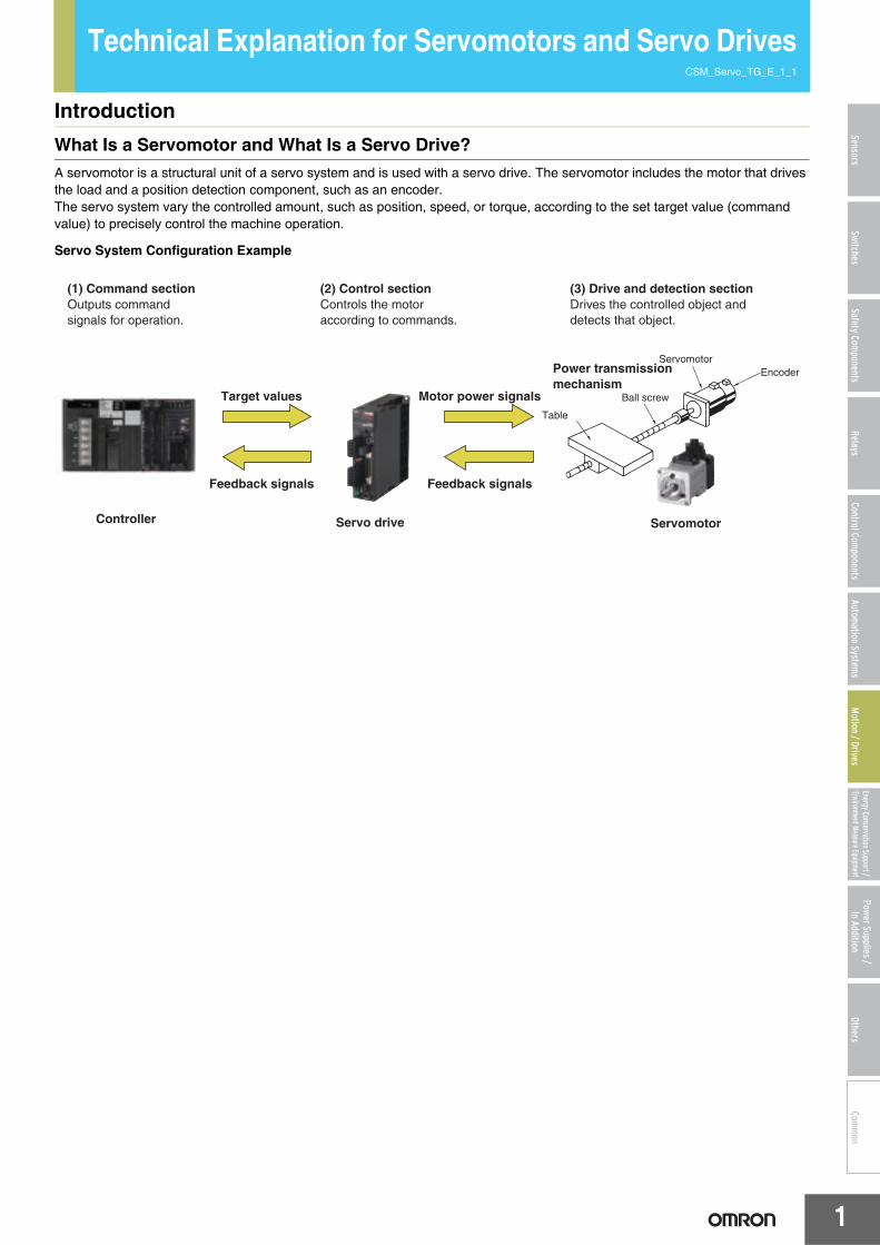
IntroductionWhat Is a Servomotor and What Is a Servo Drive?A servomotor is a structural unit of a servo system and is used with a servo drive. The servomotor includes the motor that drives the load and a position detection component, such as an encoder.The servo system vary the controlled amount, such as position, speed, or torque, according to the set target value (command value) to precisely control the machine operation.
Servo System Configuration Example
EncoderServomotor
Table
Ball screw
Servomotor
Power transmission mechanism
Servo drive
Feedback signalsFeedback signals
Motor power signalsTarget values
Controller
(1) Command section (2) Control sectionControls the motor according to commands.
Outputs command signals for operation.
(3) Drive and detection sectionDrives the controlled object and detects that object.
Technical Explanation for Servomotors and Servo Drives
2
SensorsSwitches
Safety Components
RelaysControl Com
ponentsAutom
ation Systems
Motion / Drives
Energy Conservation Support / Environment Measure Equipment
Power Supplies /In Addition
OthersCom
mon
FeaturesPrecise, High-speed Control
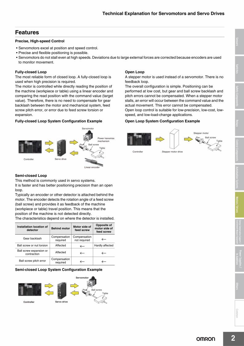
Fully-closed LoopThe most reliable form of closed loop. A fully-closed loop is used when high precision is required.The motor is controlled while directly reading the position of the machine (workpiece or table) using a linear encoder and comparing the read position with the command value (target value). Therefore, there is no need to compensate for gear backlash between the motor and mechanical system, feed screw pitch error, or error due to feed screw torsion or expansion.
Fully-closed Loop System Configuration Example
Semi-closed LoopThis method is commonly used in servo systems.It is faster and has better positioning precision than an open loop.Typically an encoder or other detector is attached behind the motor. The encoder detects the rotation angle of a feed screw (ball screw) and provides it as feedback of the machine (workpiece or table) travel position. This means that the position of the machine is not detected directly.The characteristics depend on where the detector is installed.
Semi-closed Loop System Configuration Example
Open LoopA stepper motor is used instead of a servomotor. There is no feedback loop.The overall configuration is simple. Positioning can be performed at low cost, but gear and ball screw backlash and pitch errors cannot be compensated. When a stepper motor stalls, an error will occur between the command value and the actual movement. This error cannot be compensated.Open loop control is suitable for low-precision, low-cost, low-speed, and low-load-change applications.
Open Loop System Configuration Example
• Servomotors excel at position and speed control.• Precise and flexible positioning is possible.• Servomotors do not stall even at high speeds. Deviations due to large external forces are corrected because encoders are used
to monitor movement.
Installation location of detector Behind motor Motor side of
feed screw
Opposite of motor side of
feed screw
Gear backlash Compensation required
Compensation not required
Ball screw or nut torsion Affected Hardly affected
Ball screw expansion or contraction Affected
Ball screw pitch error Compensation required
Servomotor
Power transmissimechanism
Linear encoder
Servo driveController
Ball screw
Table
Table
Ball screw
Servomotor
Servo driveController
Stepper motor drive
Stepper motor
Controller
Table
Ball screw
Technical Explanation for Servomotors and Servo Drives
3
SensorsSwitches
Safety Components
RelaysControl Com
ponentsAutom
ation Systems
Motion / Drives
Energy Conservation Support / Environment Measure Equipment
Power Supplies /In Addition
OthersCom
mon
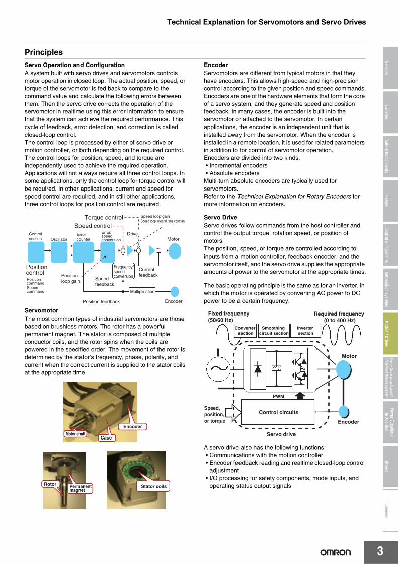
PrinciplesServo Operation and ConfigurationA system built with servo drives and servomotors controls motor operation in closed loop. The actual position, speed, or torque of the servomotor is fed back to compare to the command value and calculate the following errors between them. Then the servo drive corrects the operation of the servomotor in realtime using this error information to ensure that the system can achieve the required performance. This cycle of feedback, error detection, and correction is called closed-loop control.The control loop is processed by either of servo drive or motion controller, or both depending on the required control. The control loops for position, speed, and torque are independently used to achieve the required operation. Applications will not always require all three control loops. In some applications, only the control loop for torque control will be required. In other applications, current and speed for speed control are required, and in still other applications, three control loops for position control are required.
ServomotorThe most common types of industrial servomotors are those based on brushless motors. The rotor has a powerful permanent magnet. The stator is composed of multiple conductor coils, and the rotor spins when the coils are powered in the specified order. The movement of the rotor is determined by the stator’s frequency, phase, polarity, and current when the correct current is supplied to the stator coils at the appropriate time.
EncoderServomotors are different from typical motors in that they have encoders. This allows high-speed and high-precision control according to the given position and speed commands.Encoders are one of the hardware elements that form the core of a servo system, and they generate speed and position feedback. In many cases, the encoder is built into the servomotor or attached to the servomotor. In certain applications, the encoder is an independent unit that is installed away from the servomotor. When the encoder is installed in a remote location, it is used for related parameters in addition to for control of servomotor operation.Encoders are divided into two kinds.• Incremental encoders• Absolute encoders
Multi-turn absolute encoders are typically used for servomotors.Refer to the Technical Explanation for Rotary Encoders for more information on encoders.
Servo DriveServo drives follow commands from the host controller and control the output torque, rotation speed, or position of motors.The position, speed, or torque are controlled according to inputs from a motion controller, feedback encoder, and the servomotor itself, and the servo drive supplies the appropriate amounts of power to the servomotor at the appropriate times.
The basic operating principle is the same as for an inverter, in which the motor is operated by converting AC power to DC power to be a certain frequency.
A servo drive also has the following functions.• Communications with the motion controller• Encoder feedback reading and realtime closed-loop control
adjustment• I/O processing for safety components, mode inputs, and
operating status output signals
Speed controlControl section Oscillator
Error counter Motor
Encoder
Position controlPosition commandSpeed command
Position feedback
Speed feedback
Current feedback
Torque control
Position loop gain
Error/speed conversion
Frequency/speed conversion
Multiplication
Drive
Speed loop gain Speed loop integral time constant
Motor shaftCase
Encoder
Rotor Permanent magnet
Stator coils
Speed, position, or torque
Control circuits
PWM
Encoder
Motor
Smoothing circuit section
Inverter section
Converter section
Servo drive
Fixed frequency (50/60 Hz)
Required frequency (0 to 400 Hz)
Technical Explanation for Servomotors and Servo Drives
4
SensorsSwitches
Safety Components
RelaysControl Com
ponentsAutom
ation Systems
Motion / Drives
Energy Conservation Support / Environment Measure Equipment
Power Supplies /In Addition
OthersCom
mon
Explanation of TermsPerformanceEffective TorqueA value of the average torque (RMS) that is produced during operation of a motor.A motor with a larger value than the effective torque must be chosen.The unit is N·m.
Torque ConstantWhen a current flows to a motor, the current and the flux produce a torque.The torque constant is the relationship between this current and the produced torque. The higher the torque, the smaller the controlling current.The unit is N·m/A.
Power RateThe power rate is given by this formula: Power rate = (Rated torque) 2/Rotor inertia x 10-3.The higher the value is, the better the response is.The unit is kW/s.
Rotor InertiaThe moment of inertia of the rotor, expressed in Jm.The smaller the value is, the quicker the response is.The unit is kg·m2.
Applicable Load InertiaThe range in which a drive can control the load inertia.The range is limited by the gain adjustment range and the energy absorption capacity. The unit is kg·m2.
Rated OutputThe rated output (P) is the mechanical power that a motor can output.The rated torque (T) and the rated speed (N) are related to the rated power as follows:P=0.105×T×N
Electrical Time ConstantThe transient response time to the current that flows to the armature of a motor to which a power supply voltage is applied.It is expressed by this formula: Electrical time constant = Armature inductance/Armature resistance.Because a smaller value enables the current wave to rise more quickly, the transient response time to the current is faster.
BacklashThe mechanical system has a dead zone between forward and reverse.A gear that changes from forward to reverse must turn by the amount of the dead zone before turning the specified amount.This movement is called the backlash.Backlash is given in minutes. One turn is 360 degrees. One minute is 1/60 of 1 degree.The smaller the backlash is, the less the dead zone is.
Regeneration ResistanceA resistor that absorbs regenerative energy. Regenerative energy is the energy generated by a motor when the motor operates.A servo drive uses internal regenerative processing circuits to absorb the regenerative energy generated by a motor when the motor decelerates to prevent the DC voltage from increasing.If the regenerative energy from the motor is too large, an overvoltage can occur.To prevent overvoltages, the operation pattern must be changed to reduce the regenerative energy or an external regenerative resistor must be connected to increase the capacity to process regenerative energy.
Vibration ClassA class based on the value of the vibration measured at the shaft of a motor rotating at the rated speed without a load.There are five vibration classes into which the measured total amplitudes are divided.
Position Control ModeA control mode in which positioning commands are input from a controller and positioning is controlled using the target values in the commands.
Closed LoopA control method that compares the position commanded by the controller and the actual motor position.An error signal is returned to the controller and used to give the system the correct position.Closed-loop control can be performed based on the speed, acceleration, or torque in addition to the position.The motion control method without using feedback is called open loop.
Open LoopA control method in which the results of movement are not compared with the actuator reference.When the controller commands the motor to move, it is assumed that the requested movement will be completed.
Control LoopIn process control, a control loop adjusts a target variable by adjusting other variables using feedback and error correction.In motion control, control loops are set for speed, acceleration, position, or torque.
Technical Explanation for Servomotors and Servo Drives
5
SensorsSwitches
Safety Components
RelaysControl Com
ponentsAutom
ation Systems
Motion / Drives
Energy Conservation Support / Environment Measure Equipment
Power Supplies /In Addition
OthersCom
mon
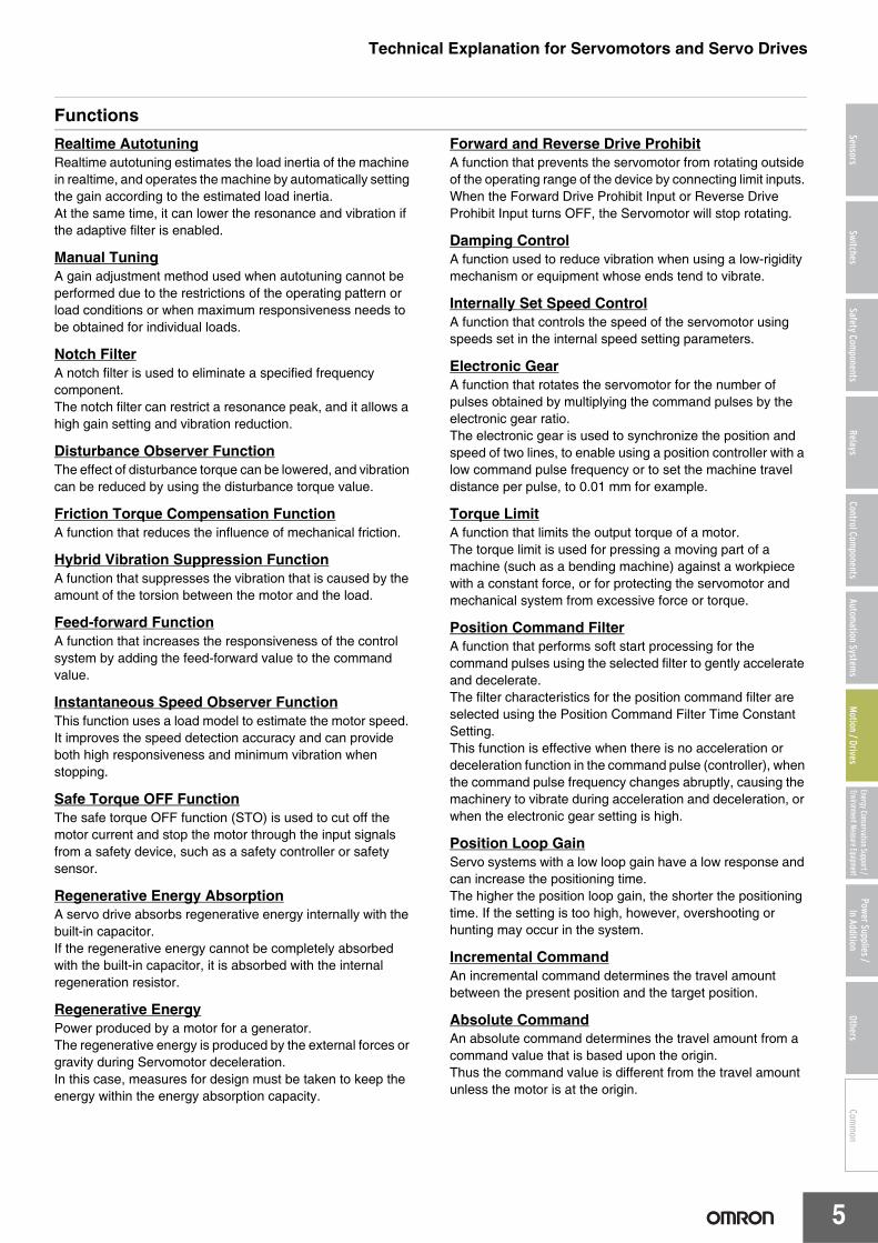
FunctionsRealtime AutotuningRealtime autotuning estimates the load inertia of the machine in realtime, and operates the machine by automatically setting the gain according to the estimated load inertia.At the same time, it can lower the resonance and vibration if the adaptive filter is enabled.
Manual TuningA gain adjustment method used when autotuning cannot be performed due to the restrictions of the operating pattern or load conditions or when maximum responsiveness needs to be obtained for individual loads.
Notch FilterA notch filter is used to eliminate a specified frequency component.The notch filter can restrict a resonance peak, and it allows a high gain setting and vibration reduction.
Disturbance Observer FunctionThe effect of disturbance torque can be lowered, and vibration can be reduced by using the disturbance torque value.
Friction Torque Compensation FunctionA function that reduces the influence of mechanical friction.
Hybrid Vibration Suppression FunctionA function that suppresses the vibration that is caused by the amount of the torsion between the motor and the load.
Feed-forward FunctionA function that increases the responsiveness of the control system by adding the feed-forward value to the command value.
Instantaneous Speed Observer FunctionThis function uses a load model to estimate the motor speed. It improves the speed detection accuracy and can provide both high responsiveness and minimum vibration when stopping.
Safe Torque OFF FunctionThe safe torque OFF function (STO) is used to cut off the motor current and stop the motor through the input signals from a safety device, such as a safety controller or safety sensor.
Regenerative Energy AbsorptionA servo drive absorbs regenerative energy internally with the built-in capacitor.If the regenerative energy cannot be completely absorbed with the built-in capacitor, it is absorbed with the internal regeneration resistor.
Regenerative EnergyPower produced by a motor for a generator.The regenerative energy is produced by the external forces or gravity during Servomotor deceleration.In this case, measures for design must be taken to keep the energy within the energy absorption capacity.
Forward and Reverse Drive ProhibitA function that prevents the servomotor from rotating outside of the operating range of the device by connecting limit inputs. When the Forward Drive Prohibit Input or Reverse Drive Prohibit Input turns OFF, the Servomotor will stop rotating.
Damping ControlA function used to reduce vibration when using a low-rigidity mechanism or equipment whose ends tend to vibrate.
Internally Set Speed ControlA function that controls the speed of the servomotor using speeds set in the internal speed setting parameters.
Electronic GearA function that rotates the servomotor for the number of pulses obtained by multiplying the command pulses by the electronic gear ratio. The electronic gear is used to synchronize the position and speed of two lines, to enable using a position controller with a low command pulse frequency or to set the machine travel distance per pulse, to 0.01 mm for example.
Torque LimitA function that limits the output torque of a motor.The torque limit is used for pressing a moving part of a machine (such as a bending machine) against a workpiece with a constant force, or for protecting the servomotor and mechanical system from excessive force or torque.
Position Command FilterA function that performs soft start processing for the command pulses using the selected filter to gently accelerate and decelerate.The filter characteristics for the position command filter are selected using the Position Command Filter Time Constant Setting.This function is effective when there is no acceleration or deceleration function in the command pulse (controller), when the command pulse frequency changes abruptly, causing the machinery to vibrate during acceleration and deceleration, or when the electronic gear setting is high.
Position Loop GainServo systems with a low loop gain have a low response and can increase the positioning time.The higher the position loop gain, the shorter the positioning time. If the setting is too high, however, overshooting or hunting may occur in the system.
Incremental CommandAn incremental command determines the travel amount between the present position and the target position.
Absolute CommandAn absolute command determines the travel amount from a command value that is based upon the origin.Thus the command value is different from the travel amount unless the motor is at the origin.
Technical Explanation for Servomotors and Servo Drives
6
SensorsSwitches
Safety Components
RelaysControl Com
ponentsAutom
ation Systems
Motion / Drives
Energy Conservation Support / Environment Measure Equipment
Power Supplies /In Addition
OthersCom
mon
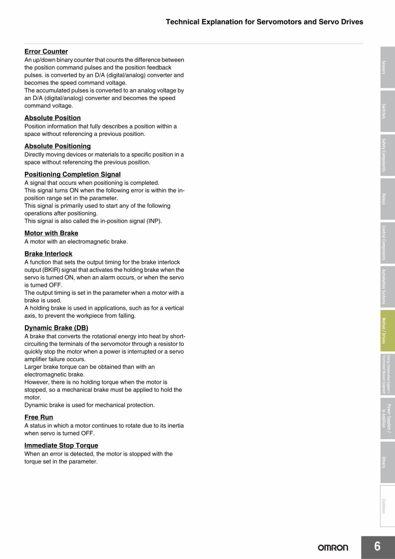
Error CounterAn up/down binary counter that counts the difference between the position command pulses and the position feedback pulses. is converted by an D/A (digital/analog) converter and becomes the speed command voltage.The accumulated pulses is converted to an analog voltage by an D/A (digital/analog) converter and becomes the speed command voltage.
Absolute PositionPosition information that fully describes a position within a space without referencing a previous position.
Absolute PositioningDirectly moving devices or materials to a specific position in a space without referencing the previous position.
Positioning Completion SignalA signal that occurs when positioning is completed.This signal turns ON when the following error is within the in-position range set in the parameter.This signal is primarily used to start any of the following operations after positioning.This signal is also called the in-position signal (INP).
Motor with BrakeA motor with an electromagnetic brake.
Brake InterlockA function that sets the output timing for the brake interlock output (BKIR) signal that activates the holding brake when the servo is turned ON, when an alarm occurs, or when the servo is turned OFF.The output timing is set in the parameter when a motor with a brake is used.A holding brake is used in applications, such as for a vertical axis, to prevent the workpiece from falling.
Dynamic Brake (DB)A brake that converts the rotational energy into heat by short-circuiting the terminals of the servomotor through a resistor to quickly stop the motor when a power is interrupted or a servo amplifier failure occurs.Larger brake torque can be obtained than with an electromagnetic brake.However, there is no holding torque when the motor is stopped, so a mechanical brake must be applied to hold the motor.Dynamic brake is used for mechanical protection.
Free RunA status in which a motor continues to rotate due to its inertia when servo is turned OFF.
Immediate Stop TorqueWhen an error is detected, the motor is stopped with the torque set in the parameter.
Technical Explanation for Servomotors and Servo Drives
7
SensorsSwitches
Safety Components
RelaysControl Com
ponentsAutom
ation Systems
Motion / Drives
Energy Conservation Support / Environment Measure Equipment
Power Supplies /In Addition
OthersCom
mon
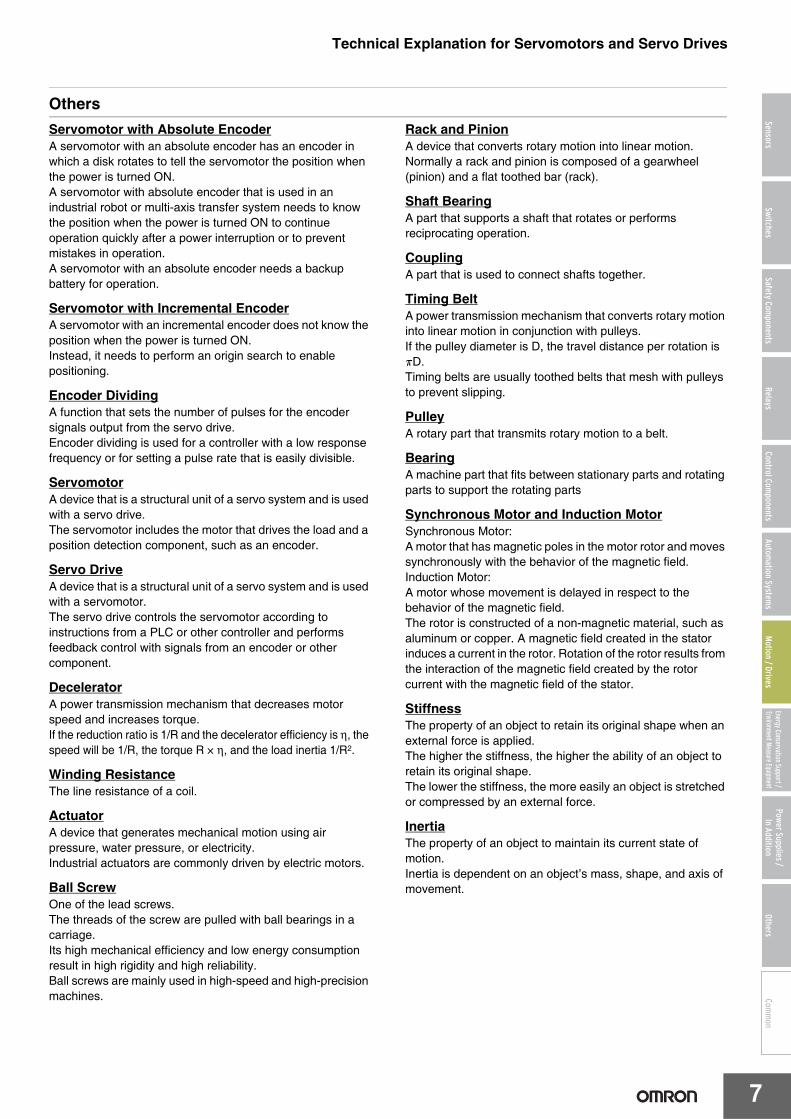
OthersServomotor with Absolute EncoderA servomotor with an absolute encoder has an encoder in which a disk rotates to tell the servomotor the position when the power is turned ON.A servomotor with absolute encoder that is used in an industrial robot or multi-axis transfer system needs to know the position when the power is turned ON to continue operation quickly after a power interruption or to prevent mistakes in operation.A servomotor with an absolute encoder needs a backup battery for operation.
Servomotor with Incremental EncoderA servomotor with an incremental encoder does not know the position when the power is turned ON.Instead, it needs to perform an origin search to enable positioning.
Encoder DividingA function that sets the number of pulses for the encoder signals output from the servo drive. Encoder dividing is used for a controller with a low response frequency or for setting a pulse rate that is easily divisible.
ServomotorA device that is a structural unit of a servo system and is used with a servo drive.The servomotor includes the motor that drives the load and a position detection component, such as an encoder.
Servo DriveA device that is a structural unit of a servo system and is used with a servomotor.The servo drive controls the servomotor according to instructions from a PLC or other controller and performs feedback control with signals from an encoder or other component.
DeceleratorA power transmission mechanism that decreases motor speed and increases torque.If the reduction ratio is 1/R and the decelerator efficiency is η, the speed will be 1/R, the torque R × η, and the load inertia 1/R2.
Winding ResistanceThe line resistance of a coil.
ActuatorA device that generates mechanical motion using air pressure, water pressure, or electricity.Industrial actuators are commonly driven by electric motors.
Ball ScrewOne of the lead screws.The threads of the screw are pulled with ball bearings in a carriage.Its high mechanical efficiency and low energy consumption result in high rigidity and high reliability.Ball screws are mainly used in high-speed and high-precision machines.
Rack and PinionA device that converts rotary motion into linear motion.Normally a rack and pinion is composed of a gearwheel (pinion) and a flat toothed bar (rack).
Shaft BearingA part that supports a shaft that rotates or performs reciprocating operation.
CouplingA part that is used to connect shafts together.
Timing BeltA power transmission mechanism that converts rotary motion into linear motion in conjunction with pulleys.If the pulley diameter is D, the travel distance per rotation is πD.Timing belts are usually toothed belts that mesh with pulleys to prevent slipping.
PulleyA rotary part that transmits rotary motion to a belt.
BearingA machine part that fits between stationary parts and rotating parts to support the rotating parts
Synchronous Motor and Induction MotorSynchronous Motor:A motor that has magnetic poles in the motor rotor and moves synchronously with the behavior of the magnetic field.Induction Motor:A motor whose movement is delayed in respect to the behavior of the magnetic field.The rotor is constructed of a non-magnetic material, such as aluminum or copper. A magnetic field created in the stator induces a current in the rotor. Rotation of the rotor results from the interaction of the magnetic field created by the rotor current with the magnetic field of the stator.
StiffnessThe property of an object to retain its original shape when an external force is applied.The higher the stiffness, the higher the ability of an object to retain its original shape.The lower the stiffness, the more easily an object is stretched or compressed by an external force.
InertiaThe property of an object to maintain its current state of motion.Inertia is dependent on an object’s mass, shape, and axis of movement.
Technical Explanation for Servomotors and Servo Drives
8
SensorsSwitches
Safety Components
RelaysControl Com
ponentsAutom
ation Systems
Motion / Drives
Energy Conservation Support / Environment Measure Equipment
Power Supplies /In Addition
OthersCom
mon
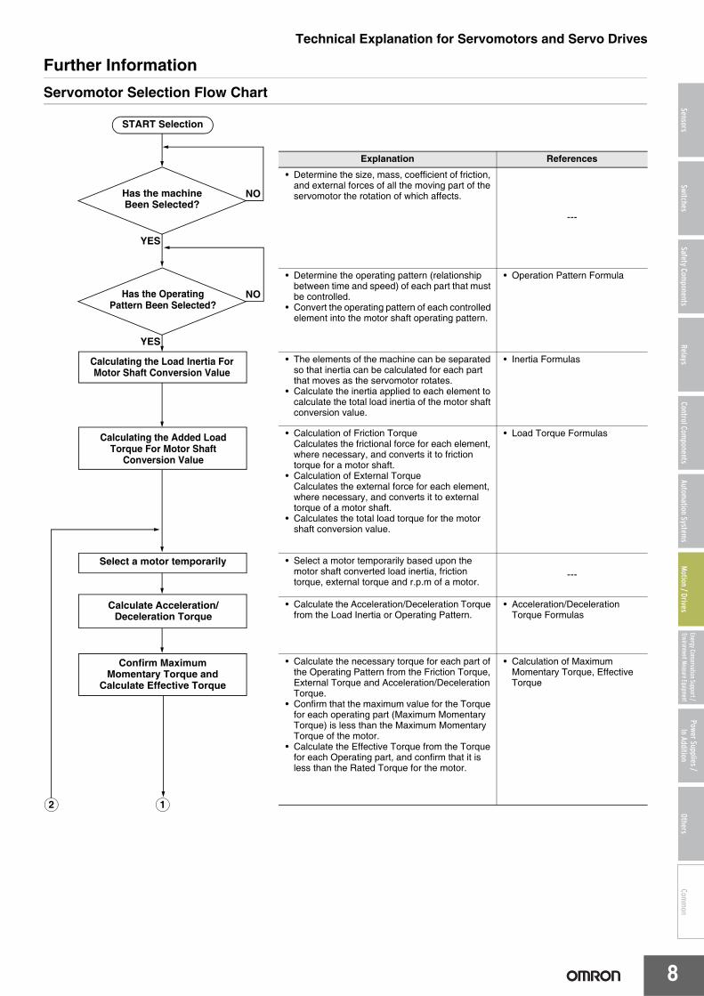
Further InformationServomotor Selection Flow Chart
Explanation References
• Determine the size, mass, coefficient of friction, and external forces of all the moving part of the servomotor the rotation of which affects.
---
• Determine the operating pattern (relationship between time and speed) of each part that must be controlled.
• Convert the operating pattern of each controlled element into the motor shaft operating pattern.
• Operation Pattern Formula
• The elements of the machine can be separated so that inertia can be calculated for each part that moves as the servomotor rotates.
• Calculate the inertia applied to each element to calculate the total load inertia of the motor shaft conversion value.
• Inertia Formulas
• Calculation of Friction TorqueCalculates the frictional force for each element, where necessary, and converts it to friction torque for a motor shaft.
• Calculation of External TorqueCalculates the external force for each element, where necessary, and converts it to external torque of a motor shaft.
• Calculates the total load torque for the motor shaft conversion value.
• Load Torque Formulas
• Select a motor temporarily based upon the motor shaft converted load inertia, friction torque, external torque and r.p.m of a motor.
---
• Calculate the Acceleration/Deceleration Torque from the Load Inertia or Operating Pattern.
• Acceleration/Deceleration Torque Formulas
• Calculate the necessary torque for each part of the Operating Pattern from the Friction Torque, External Torque and Acceleration/Deceleration Torque.
• Confirm that the maximum value for the Torque for each operating part (Maximum Momentary Torque) is less than the Maximum Momentary Torque of the motor.
• Calculate the Effective Torque from the Torque for each Operating part, and confirm that it is less than the Rated Torque for the motor.
• Calculation of Maximum Momentary Torque, Effective Torque
Has the Operating Pattern Been Selected?
NO
YES
START Selection
Has the machineBeen Selected?
NO
YES
Calculating the Load Inertia For Motor Shaft Conversion Value
Calculating the Added Load Torque For Motor Shaft
Conversion Value
Select a motor temporarily
Calculate Acceleration/Deceleration Torque
Confirm Maximum Momentary Torque and
Calculate Effective Torque
12
Technical Explanation for Servomotors and Servo Drives
9
SensorsSwitches
Safety Components
RelaysControl Com
ponentsAutom
ation Systems
Motion / Drives
Energy Conservation Support / Environment Measure Equipment
Power Supplies /In Addition
OthersCom
mon
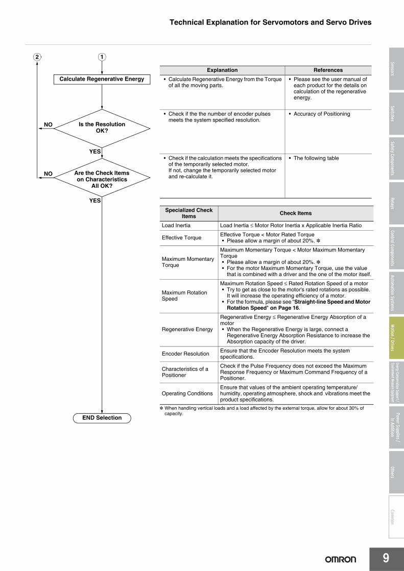
* When handling vertical loads and a load affected by the external torque, allow for about 30% of capacity.
Explanation References
• Calculate Regenerative Energy from the Torque of all the moving parts.
• Please see the user manual of each product for the details on calculation of the regenerative energy.
• Check if the the number of encoder pulses meets the system specified resolution.
• Accuracy of Positioning
• Check if the calculation meets the specifications of the temporarily selected motor.If not, change the temporarily selected motor and re-calculate it.
• The following table
2
NO
Is the ResolutionOK?
YES
END Selection
Calculate Regenerative Energy
1
YES
NO
Are the Check Items on Characteristics
All OK?
Specialized Check Items Check Items
Load Inertia Load Inertia ≤ Motor Rotor Inertia x Applicable Inertia Ratio
Effective Torque Effective Torque < Motor Rated Torque• Please allow a margin of about 20%. *
Maximum Momentary Torque
Maximum Momentary Torque < Motor Maximum Momentary Torque• Please allow a margin of about 20%. *• For the motor Maximum Momentary Torque, use the value
that is combined with a driver and the one of the motor itself.
Maximum Rotation Speed
Maximum Rotation Speed ≤ Rated Rotation Speed of a motor• Try to get as close to the motor's rated rotations as possible.
It will increase the operating efficiency of a motor.• For the formula, please see "Straight-line Speed and Motor
Rotation Speed" on Page 16.
Regenerative Energy
Regenerative Energy ≤ Regenerative Energy Absorption of a motor• When the Regenerative Energy is large, connect a
Regenerative Energy Absorption Resistance to increase the Absorption capacity of the driver.
Encoder Resolution Ensure that the Encoder Resolution meets the system specifications.
Characteristics of a Positioner
Check if the Pulse Frequency does not exceed the Maximum Response Frequency or Maximum Command Frequency of a Positioner.
Operating ConditionsEnsure that values of the ambient operating temperature/humidity, operating atmosphere, shock and vibrations meet the product specifications.
Technical Explanation for Servomotors and Servo Drives
10
SensorsSwitches
Safety Components
RelaysControl Com
ponentsAutom
ation Systems
Motion / Drives
Energy Conservation Support / Environment Measure Equipment
Power Supplies /In Addition
OthersCom
mon
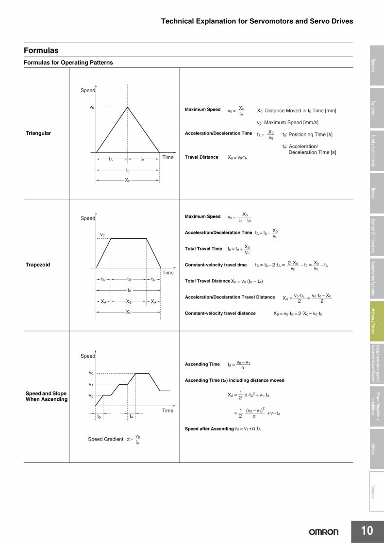
FormulasFormulas for Operating Patterns
Triangular
Maximum Speed
Acceleration/Deceleration Time
Travel Distance
Trapezoid
Maximum Speed
Acceleration/Deceleration Time
Total Travel Time
Constant-velocity travel time
Total Travel Distance
Acceleration/Deceleration Travel Distance
Constant-velocity travel distance
Speed and Slope When Ascending
Ascending Time
Ascending Time (tA) including distance moved
Speed after Ascending
Time
Speed
tA tA
t0
X0
v0X0: Distance Moved in t0 Time [mm]
v0: Maximum Speed [mm/s]
v0 =X0
tA
t0: Positioning Time [s]
tA: Acceleration/ Deceleration Time [s]
tA =X0
v0
X0 = v0·tA
TimetA tB
t0
tA
XA XB
X0
XA
v0
Speed v0 =X0
t0 – tA
tA = t0 – X0
v0
t0 = tA +X0
v0
X0
v0tB = t0 – 2·tA = 2·X0
v0 – t0 = – tA
X0 = v0 (t0 – tA)
XA = v0·tA2
v0·t0 – X0
2=
XB = v0·tB = 2·X0 – v0·t0
Timetg tA
v0
v1
vg
Speed Gradientvg
tg
Speed
tA = v0 – v1
α
XA =12α·tA2
+ v1·tA
12
XA =(v0 – v1)
2
α +v1·tA
v0 = v1+α·tA
Technical Explanation for Servomotors and Servo Drives
11
SensorsSwitches
Safety Components
RelaysControl Com
ponentsAutom
ation Systems
Motion / Drives
Energy Conservation Support / Environment Measure Equipment
Power Supplies /In Addition
OthersCom
mon
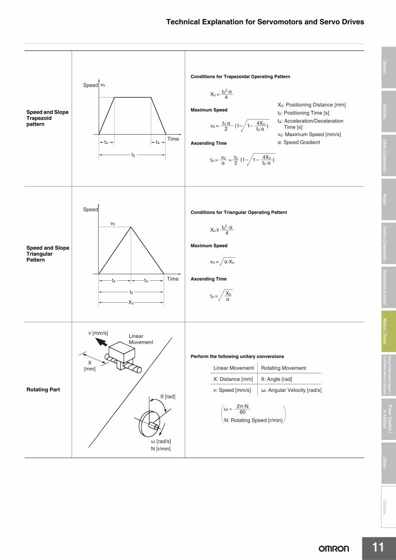
Speed and Slope Trapezoid pattern
Conditions for Trapezoidal Operating Pattern
Maximum Speed
Ascending Time
Speed and SlopeTriangular Pattern
Conditions for Triangular Operating Pattern
Maximum Speed
Ascending Time
Rotating Part
Perform the following unitary conversions
tA
t0
tA
v0
Time
Speedt02·α
4X0 <
X0: Positioning Distance [mm]
t0: Positioning Time [s]
v0 =t0·α2
4X0
t0·αtA: Acceleration/Deceleration Time [s]v0: Maximum Speed [mm/s]
α: Speed Gradient
(1– 1– )
tA =v0
αt02
4X0
t0·α(1– 1– ) =
TimetA tA
t0
X0
v0
Speed
X0≥ t02·α4
v0 = α·X0
tA =X0
α
Linear Movement
v [mm/s]
X[mm]
θ [rad]
ω [rad/s]
N [r/min]
Linear Movement Rotating Movement
X: Distance [mm]
v: Speed [mm/s]
θ: Angle [rad]
ω: Angular Velocity [rad/s]
N: Rotating Speed [r/min]
ω = 2π·N60
Technical Explanation for Servomotors and Servo Drives
12
SensorsSwitches
Safety Components
RelaysControl Com
ponentsAutom
ation Systems
Motion / Drives
Energy Conservation Support / Environment Measure Equipment
Power Supplies /In Addition
OthersCom
mon
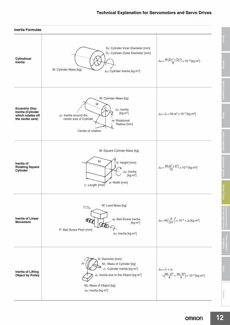
Inertia Formulas
Cylindrical Inertia
Eccentric Disc Inertia (Cylinder which rotates off the center axis)
Inertia of Rotating Square Cylinder
Inertia of Linear Movement
Inertia of Lifting Object by Pulley
JW: Cylinder Inertia [kg·m2]
D2: Cylinder Inner Diameter [mm]
M: Cylinder Mass [kg]
D1: Cylinder Outer Diameter [mm]
JW = × 10–6 [kg·m2]M (D12 + D2
2)8
JW: Inertia [kg·m2]
JC: Inertia around the center axis of Cylinder re: Rotational
Radius [mm]
Center of rotation
M: Cylinder Mass [kg]
MC
JW = JC + M·re2 × 10–6 [kg·m2]
JW: Inertia [kg·m2]
M: Square Cylinder Mass [kg]
b: Height [mm]
a: Width [mm]L: Length [mm]
M
JW = × 10–6 [kg·m2]M (a2 + b2)12
JW: Inertia [kg·m2]
JB: Ball Screw Inertia [kg·m2]
P: Ball Screw Pitch [mm]
M: Load Mass [kg]
× 10–6 + JB [kg·m2]JW = MP
2π( )2
D: Diameter [mm]
M1: Mass of Cylinder [kg]
J1: Cylinder Inertia [kg·m2]
M2: Mass of Object [kg]
JW: Inertia [kg·m2]
J2: Inertia due to the Object [kg·m2]
JW
JW = J1 + J2
× 10–6 [kg·m2] = M1·D2
8M2·D2
4( )+
Technical Explanation for Servomotors and Servo Drives
13
SensorsSwitches
Safety Components
RelaysControl Com
ponentsAutom
ation Systems
Motion / Drives
Energy Conservation Support / Environment Measure Equipment
Power Supplies /In Addition
OthersCom
mon
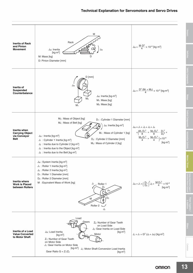
Inertia of Rack and Pinion Movement
Inertia of Suspended Counterbalance
Inertia when Carrying Object via Conveyor Belt
Inertia where Work is Placed between Rollers
Inertia of a Load Value Converted to Motor Shaft
JW: Inertia[kg·m2]
DM: Mass [kg]
D: Pinion Diameter [mm]
M
Rack
JW
JW = × 10–6 [kg·m2]M·D2
4
D [mm]
M1: Mass [kg]
JW: Inertia [kg·m2]
M2: Mass [kg]
JW
M1
M2
JW = × 10–6 [kg·m2]D2 (M1 + M2)4
JW: Inertia [kg·m2]
M1 : Mass of Cylinder 1 [kg]JW : Inertia [kg·m2]
J1 : Cylinder 1 Inertia [kg·m2]
J2 : Inertia due to Cylinder 2 [kg·m2]
J3 : Inertia due to the Object [kg·m2]
J4 : Inertia due to the Belt [kg·m2]
M3 : Mass of Object [kg]
M4 : Mass of Belt [kg]D1 : Cylinder 1 Diameter [mm]
D2 : Cylinder 2 Diameter [mm]
M2 : Mass of Cylinder 2 [kg] [kg·m2]
JW = J1 + J2 + J3 + J4
×10–6
JW = M1·D12
8M2·D2
2
8()
+
M3·D12
4M4·D1
2
4+
+D12
D22·
JW : System Inertia [kg·m2]
J1 : Roller 1 Inertia [kg·m2]
J2 : Roller 2 Inertia [kg·m2]
D1 : Roller 1 Diameter [mm]
D2 : Roller 2 Diameter [mm]
M : Equivalent Mass of Work [kg] J1
JW
M
Roller 1
Roller 2J2
D1
D2
× 10–6JW = J1 +D1
D2( )2
J2 +M·D1
2
4[kg·m2]
JL: Motor Shaft Conversion Load Inertia[kg·m2]Gear Ratio G = Z1/Z2
Z2: Number of Gear Teeth on Load Side
J2: Gear Inertia on Load Side[kg·m2]
Z1: Number of Gear Teeth on Motor Side
JW: Load Inertia [kg·m2]
J1: Gear Inertia on Motor Side [kg·m2]
LoadGears
Motor JL = J1 + G2 (J2 + JW) [kg·m2]
Technical Explanation for Servomotors and Servo Drives
14
SensorsSwitches
Safety Components
RelaysControl Com
ponentsAutom
ation Systems
Motion / Drives
Energy Conservation Support / Environment Measure Equipment
Power Supplies /In Addition
OthersCom
mon
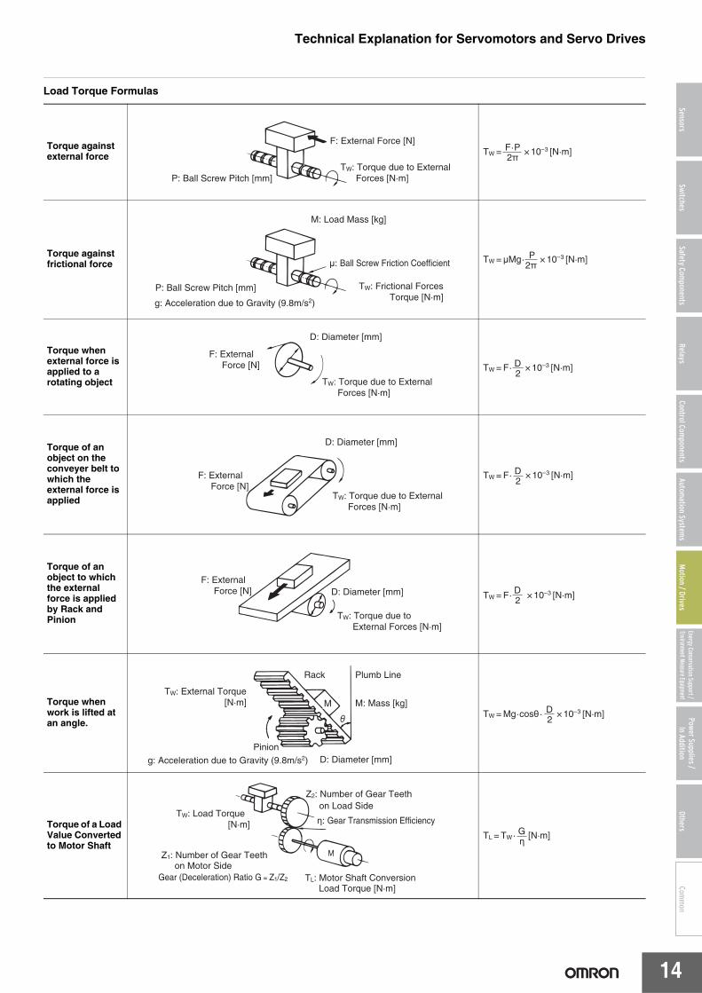
Load Torque Formulas
Torque against external force
Torque against frictional force
Torque when external force is applied to a rotating object
Torque of an object on the conveyer belt to which the external force is applied
Torque of an object to which the external force is applied by Rack and Pinion
Torque when work is lifted at an angle.
Torque of a Load Value Converted to Motor Shaft
F: External Force [N]
TW: Torque due to External Forces [N·m]P: Ball Screw Pitch [mm]
TW = × 10–3 [N·m]F·P2π
M: Load Mass [kg]
P: Ball Screw Pitch [mm]
μ: Ball Screw Friction Coefficient
g: Acceleration due to Gravity (9.8m/s2)
TW: Frictional Forces Torque [N·m]
TW = μMg· × 10–3 [N·m]P2π
F: External Force [N]
D: Diameter [mm]
TW: Torque due to External Forces [N·m]
TW = F· × 10–3 [N·m]D2
F: External Force [N]
D: Diameter [mm]
TW: Torque due to External Forces [N·m]
TW = F· × 10–3 [N·m]D2
F: External Force [N] D: Diameter [mm]
TW: Torque due to External Forces [N·m]
TW = F· × 10–3 [N·m]D2
M: Mass [kg]
D: Diameter [mm]
Plumb LineRack
Pinion
g: Acceleration due to Gravity (9.8m/s2)
TW: External Torque[N·m] M
TW = Mg·cosθ · × 10–3 [N·m]D2
Z2: Number of Gear Teeth on Load Side
η: Gear Transmission Efficiency
TL: Motor Shaft Conversion Load Torque [N·m]
Z1: Number of Gear Teeth on Motor Side
Gear (Deceleration) Ratio G = Z1/Z2
TW: Load Torque [N·m]
TL = TW· [N·m]Gη
Technical Explanation for Servomotors and Servo Drives
15
SensorsSwitches
Safety Components
RelaysControl Com
ponentsAutom
ation Systems
Motion / Drives
Energy Conservation Support / Environment Measure Equipment
Power Supplies /In Addition
OthersCom
mon
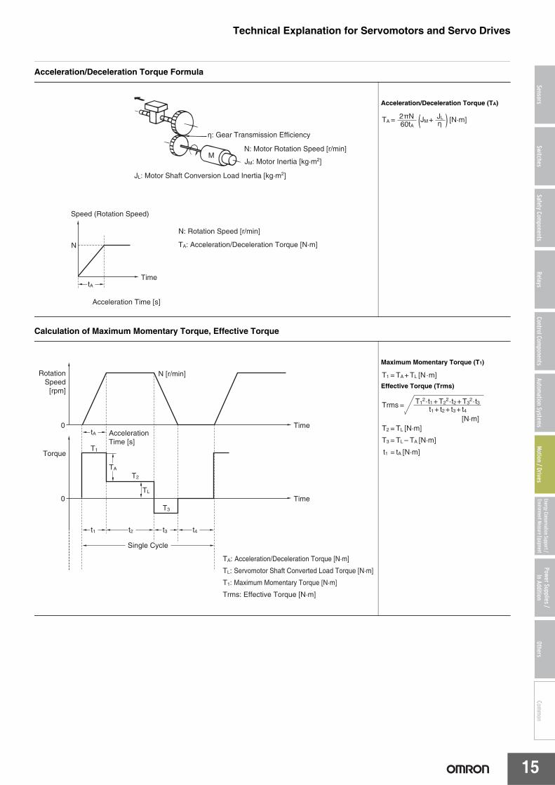
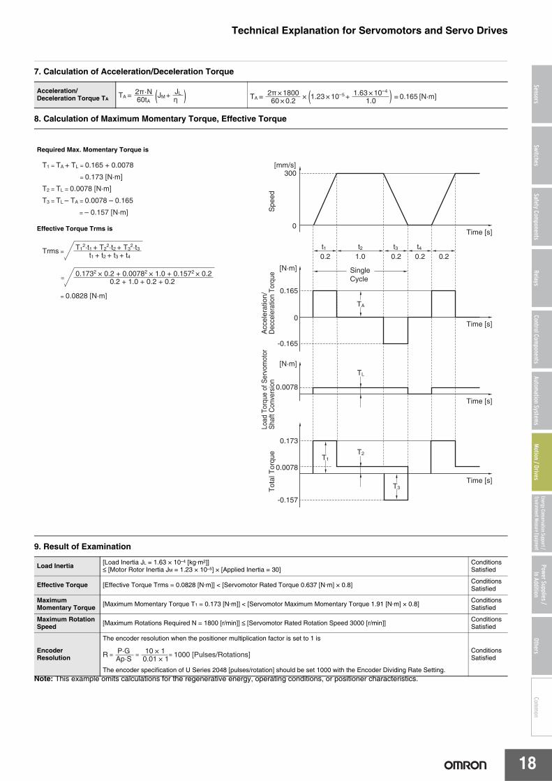
Acceleration/Deceleration Torque Formula
Calculation of Maximum Momentary Torque, Effective Torque
Acceleration/Deceleration Torque (TA)
Maximum Momentary Torque (T1)
Effective Torque (Trms)
Speed (Rotation Speed)
Acceleration Time [s]
N
TimetA
η: Gear Transmission Efficiency
N: Motor Rotation Speed [r/min]
JM: Motor Inertia [kg·m2]
N: Rotation Speed [r/min]
TA: Acceleration/Deceleration Torque [N·m]
JL: Motor Shaft Conversion Load Inertia [kg·m2]
M
TA = JM + JLη
2πN60tA ( ) [N·m]
TA: Acceleration/Deceleration Torque [N·m]
TL: Servomotor Shaft Converted Load Torque [N·m]
T1: Maximum Momentary Torque [N·m]
Trms: Effective Torque [N·m]
RotationSpeed
[rpm]
Acceleration Time [s]
0 Time
Torque
0 Time
tA
t1
TA
TL
T3
T1
T2
t3 t4t2
Single Cycle
N [r/min] T1 = TA + TL [N·m]
T2 = TL [N·m]
T3 = TL – TA [N·m]
t1 = tA [N·m]
Trms = T1
2·t1 + T22·t2 + T3
2·t3t1 + t2 + t3 + t4
[N·m]
Technical Explanation for Servomotors and Servo Drives
16
SensorsSwitches
Safety Components
RelaysControl Com
ponentsAutom
ation Systems
Motion / Drives
Energy Conservation Support / Environment Measure Equipment
Power Supplies /In Addition
OthersCom
mon
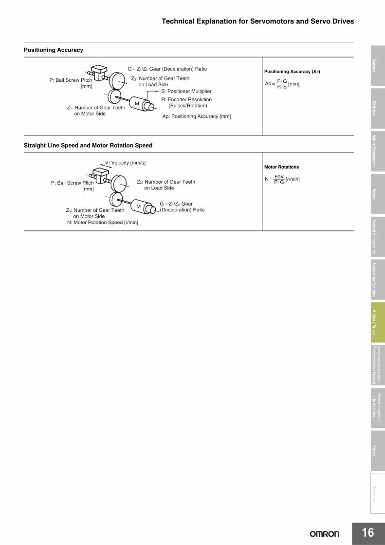
Positioning Accuracy
Straight Line Speed and Motor Rotation Speed
Positioning Accuracy (AP)
Motor Rotations
S: Positioner Multiplier
R: Encoder Resolution (Pulses/Rotation)M
G = Z1/Z2 Gear (Deceleration) Ratio
P: Ball Screw Pitch [mm]
Ap: Positioning Accuracy [mm]
Z1: Number of Gear Teeth on Motor Side
Z2: Number of Gear Teeth on Load Side Ap =
P·GR·S [mm]
M G = Z1/Z2 Gear (Deceleration) Ratio
P: Ball Screw Pitch[mm]
V: Velocity [mm/s]
Z1: Number of Gear Teeth on Motor SideN: Motor Rotation Speed [r/min]
Z2: Number of Gear Teeth on Load Side
N = 60VP·G [r/min]
Technical Explanation for Servomotors and Servo Drives
17
SensorsSwitches
Safety Components
RelaysControl Com
ponentsAutom
ation Systems
Motion / Drives
Energy Conservation Support / Environment Measure Equipment
Power Supplies /In Addition
OthersCom
mon
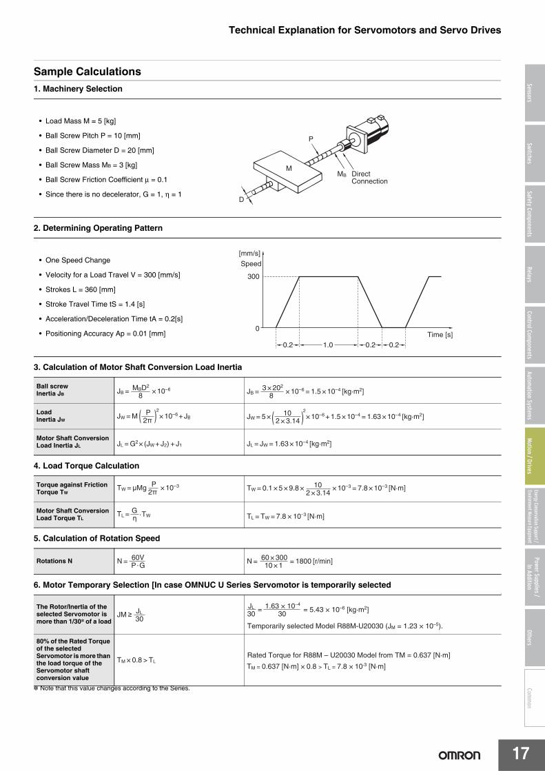
Sample Calculations1. Machinery Selection
2. Determining Operating Pattern
3. Calculation of Motor Shaft Conversion Load Inertia
4. Load Torque Calculation
5. Calculation of Rotation Speed
6. Motor Temporary Selection [In case OMNUC U Series Servomotor is temporarily selected]
* Note that this value changes according to the Series.
• Load Mass M = 5 [kg]
• Ball Screw Pitch P = 10 [mm]
• Ball Screw Diameter D = 20 [mm]
• Ball Screw Mass MB = 3 [kg]
• Ball Screw Friction Coefficient μ = 0.1
• Since there is no decelerator, G = 1, η = 1
• One Speed Change
• Velocity for a Load Travel V = 300 [mm/s]
• Strokes L = 360 [mm]
• Stroke Travel Time tS = 1.4 [s]
• Acceleration/Deceleration Time tA = 0.2[s]
• Positioning Accuracy Ap = 0.01 [mm]
Ball screwInertia JB
LoadInertia JW
Motor Shaft Conversion Load Inertia JL
Torque against Friction Torque TW
Motor Shaft Conversion Load Torque TL
Rotations N
The Rotor/Inertia of the selected Servomotor is more than 1/30* of a load
80% of the Rated Torque of the selected Servomotor is more than the load torque of the Servomotor shaft conversion value
Technical Explanation for Servomotors and Servo Drives
19
SensorsSwitches
Safety Components
RelaysControl Com
ponentsAutom
ation Systems
Motion / Drives
Energy Conservation Support / Environment Measure Equipment
Power Supplies /In Addition
OthersCom
mon
MaintenanceServomotors and Servo Drives contain many components and will operate properly only when each of the individual components is operating properly. Some of the electrical and mechanical components require maintenance depending on application conditions. In order to ensure proper long-term operation of Servomotors and Drives, periodic inspection and part replacement is required according to the life of the components. (From the "Recommendations for Periodic Inspection of Inverters", published by JEMA)
The periodic maintenance cycle depends on the installation environment and application conditions of the Servomotor or Servo Drive. Recommended maintenance times are listed below for Servomotors and Servo Drives. Use these for reference in determining actual maintenance schedules.For Servomotors and Servo Drives maintenance, please check the "User Manual (Chapter on Periodic Maintenance)" for each Series.
Servo Drive (including Power Supply unit and Regeneration Resistor)Among the components used in the Servo Drive, aluminum analytical capacitors and Axle fans in particular require periodic maintenance.The life of aluminum analytical capacitors is greatly affected by the ambient operating temperature and the load conditions of Servomotor operation.Generally speaking, an increase of 10°C in the ambient operating temperature will reduce capacitor life by 50%.Recommended maintenance times are listed below for each of the Series.
• OMNUC G5 SeriesAluminum analytical capacitors......28,000 hours(Ambient operating temperature 55°C, output of the rated operation [rated torque])Axle fan......10,000 to 30,000 hours (At an ambient Servo Drive operating temperature of 40°C or below)
• Smart Step 2 SeriesAluminum analytical capacitors......50,000 hours(Ambient operating temperature 40°C, 80% output of the rated operation [rated torque])Axle fan......30,000 hours(At an ambient Servo Drive operating temperature of 40°C and an ambient humidity of 65%)
• OMNUC G SeriesAluminum analytical capacitors......28,000 hours(Ambient operating temperature 55°C, output of the rated operation [rated torque])Axle fan......10,000 to 30,000 hours (At an ambient Servo Drive operating temperature of 40°C or below)
Please follow the instructions in the user manual for installation.We recommend that ambient operating temperature and the power ON time be reduced as much as possible to lengthen the maintenance intervals for Servo Drives.If the Servomotor or Servo Drive is not to be used for a long time, or if they are to be used under conditions worse than those described above, a periodic inspection schedule of five years is recommended.Please consult with OMRON to determine whether or not components need to be replaced.
ServomotorAmong the components used by the Servomotor, Aluminum Analytical Capacitors, Bearings, Oil seal and Brush require periodic maintenance. Their life will depend on such factors as the number of rotations used for, the temperature, and the load on bearings. Recommended maintenance times are listed below for each of the Series.
• OMNUC G SeriesBearings ..........................20,000 hoursOil Seals ..........................5,000 hours
Application Conditions: Ambient Servomotor operating temperature of 40°C, within allowable shaft load, rated operation (rated torque and r/min), installed as described in operation manual.