Technical Feasibility of an Integral Fast Reactor (IFR) as a Future Option for Fast Reactor Cycles -Integrate a Small Metal-Fueled Fast Reactor and Pyroprocessing Facilities- FINAL Report Research Project on “Sustainability of Nuclear” November 30, 2016 The Sasakawa Peace Foundation
Transcript
Technical Feasibility of an Integral Fast Reactor (IFR)
as a Future Option for Fast Reactor Cycles -Integrate a Small Metal-Fueled Fast Reactor
and Pyroprocessing Facilities-
FINAL Report
Research Project on
“Sustainability of Nuclear”
November 30, 2016
The Sasakawa Peace Foundation
1
1. Foreword
1.1 Objectives
The concept of an Integral Fast Reactor (IFR), which integrates a sodium-cooled small
metal-fueled fast reactor with pyroprocessing facilities, could be an option for future fast
reactor cycles. Combination of the sodium-cooled fast reactor (SFR) with metallic fuel core
and pyroprocessing has been considered second to that of the SFR with MOX fuel core and
the aqueous reprocessing in the national project on the commercialization of the fast reactor
cycle systems in Japan [1]. Basic and generic researches have been carried out in this area.
In order to research the technical feasibility of this IFR concept, the technical viability and
issues standing in the way of verifying the potential to reduce both the volume of
radioactive waste and the level of hazard (radiotoxicity) were examined by using the
example of processing the fuel debris generated in conjunction with the TEPCO (currently
Tokyo Electric Power Company Holdings, Incorporated) Fukushima Daiichi Nuclear Power
Station (1F NPS) Accident of March 2011. The process consists of fabricating fuel from the
transuranium (TRU) elements such as plutonium, neptunium and americium which were
recovered through fuel debris reprocessing and burning this fuel in the reactor thereby
gradually reducing TRU. Potential research topics for cooperation between the US and
Japan in the field of fast reactor cycles shall also be examined.
In particular, the technical feasibility and issues that need to be solved have been
summarized in regard to pyroprocessing methods, which are thought to be effective at
processing fuel debris, and the concept of a small metal-fueled fast reactor, which is
superior in terms of safety.
Necessary measures to treat fuel debris will be determined after the removal of the debris
from the plants. In this study, however, the IFR concept that can reduce the amount of TRU
in the debris by reprocessing debris, fabricating fuels with recovered U and TRU, and
burning TRU in a small SFR will be examined as one of the debris treatment options.
1.2 Assignment of Research Issues
The following topics were researched individually in order to examine the technical
feasibility of a system for processing fuel debris from the 1F NPS and recycling it as fuel in
a reactor.
(1) Examination of the concept of pyroprocessing systems
(2) Examination of the concept of a small metal-fueled fast reactor
(3) Evaluation of the safety design concept of a small metal-fueled fast reactor
2
1.3 Research Period
October 1, 2015 through November 30, 2016
1.4 Implementation Method
The Sasakawa Peace Foundation consigned manufacturers to research the technical
feasibility of each of the topics.
(1) Examination of the concept of pyroprocessing systems (Toshiba Corporation)
(2) Examination of the concept of a small metal-fueled fast reactor (Hitachi-GE Nuclear
Energy, Ltd.)
(3) Evaluation of the safety design concept of a small metal-fueled fast reactor (Mitsubishi
Heavy Industries, Ltd.)
During the examination of these topics a workshop comprised of Japanese experts was
formed. Nuclear Salon (NSF) was contracted by the Sasakawa Peace Foundation to serve as
the secretariat for the workshop and the workshop continued to debate these subjects while
receiving periodic reports from the three manufacturers consigned to do the research.
Meetings were held three times in JFY 2015 and three times in JFY 2016. Furthermore,
on August 26, 2016, experts in the fields of reactor safety and pyroprocessing (Dr. Tanju
Sofu and Dr. Mark A. Williamson, respectively) were invited from the Argonne National
Laboratory (ANL) in the United States (US) to exchange opinions with the members of the
workshop. In addition, a debrief meeting upon the research project on “Sustainability of
Nuclear” was held on November 18, 2016 where three experts in the fields of fast reactor
cycles, energy technologies and innovative technologies from the US Department of Energy,
ANL and the Columbia University (Dr. Sal J. Golub, Dr. Yoon I. Chang and Dr. Nicola De
Blasio, respectively) were invited. In this meeting, the result of this study was reported
mainly for the people associated with nuclear engineering and/or Fukushima and related
discussion was conducted.
The members of the workshop are as follows:
Chairman: Yutaka Sagayama, Assistant to the President, Japan Atomic Energy
Agency (JAEA)
Members: Yoichi Fuji-ie, Representative Director, NPO Nuclear Salon
Akira Yamaguchi, Professor, Department of Nuclear Engineering
and Management, the University of Tokyo
Koji Morita, Professor, Department of Applied Quantum Physics
and Nuclear Engineering, Faculty of Engineering, Kyushu
University
3
Reiko Fujita, Program Manager, Impulsing Paradigm Change
through Disruptive Technologies (ImPACT), Japan Science and
Technology Agency
Takanari Ogata, Fuel and Core Region Leader, Nuclear
Technology Research Laboratory, Central Research Institute of
Electric Power Industry
Shoji Kotake, Executive Officer, Projects Development
Department, the Japan Atomic Power Company
Observers: Koji Sato, Japan Atomic Energy Agency
Takashi Namba, Japan Atomic Energy Agency
Consigned Technical Research Teams:
Toshiba Corporation
Hitachi-GE Nuclear Energy, Ltd
Mitsubishi Heavy Industries, Ltd.
The Sasakawa Peace Foundation: President, Nobuo Tanaka and related persons
4
2. Research Results
The IFR concept, or rather, a closed fuel cycle system that combines a small SFR that has
inherent safety features with a pyrochemical reprocessing facility and an injection casting fuel
fabrication facility all on the same site, was proposed in 1984 by ANL.
This system has the following characteristics:
- Effective utilization of uranium resources: fuel breeding using fast neutrons
- Inherent safety features (passive safety): Many core reactivity coefficients are
negative thereby producing a large negative feedback to increases in coolant
temperature
- Waste management: Reduction in the amount of radioactive waste generated and
decreases in long-term radiotoxicity (hazard level) through the burning of minor
- High proliferation resistance: The employment of pyroprocessing by which
plutonium cannot be separated and fuel transport is unnecessary due to the
co-location of reactor and fuel cycle systems
- Economic competitiveness: Compact, closed fuel cycle, a small fast reactor
(factory-produced, assembled on site)
The IFR concept was constructed through research and development (R&D) using the
experimental fast breeder reactor EBR-II and associated fuel cycle facilities. From 1985
the US Department of Energy conducted R&D on this type of metal-fueled pool reactors
as part of its advanced liquid metal reactor project, but this project was cancelled by the
US Congress in 1994.
However, General Electric Co. (GE) in the US (currently GE-Hitachi Nuclear Energy,
Ltd. (GEH)) continued its R&D on Power Reactor Innovative Small Modules (PRISM),
and in 2012 GEH made a public appeal to combine the concept of PRISM with an
advanced recycling center as a solution to the problem of disposing of UK’s plutonium
inventory (the management of the UK’s large plutonium stockpile).
In order to investigate the technical feasibility of this IFR concept as a future option for
fast reactor cycles in Japan, processing of fuel debris from the TEPCO 1F NPS was
examined as an example.
2.1 Fuel Debris from TEPCO 1F NPS
As a result of the tsunami created in conjunction with the Great Eastern Japan Earthquake
on March 11, 2011, the TEPCO 1F NPS lost all electric power supply thereby causing a
serious accident in which the fuel in Units 1-3 melted. In the course of the accident
progression, melted fuel was presumed to react with the cladding tube, i.e. the sheath for the
5
fuel, and other structural materials such as the reactor vessel, thereby transforming into
materials with complicated compositions and shapes. They are referred to as fuel debris.
Melted fuel may accumulate in the reactor vessel as fuel debris (core region debris), or in
some cases, it may melt through the reactor vessel to the outside. In this case, the melted
fuel would react with concrete thereby generating fuel debris with an even more
complicated chemical composition and shape (MCCI1 debris).
How to handle this fuel debris is an important issue that must be solved in order to
decommission the 1F NPS. Therefore, we have examined a system for appropriately
processing this fuel debris using a pyroprocessing method, extracting the uranium and TRU
from the fuel debris, using the recovered TRU to fabricate fuel and recycling it in a small
metal-fueled fast reactor with inherent safety.
When examining processing methods, it is necessary to understand the composition of
fuel debris. However, at current time we have not been able to sample the fuel debris inside
the plants and subject it to analysis.
During this research, we examined past knowledge concerning debris characteristics and
composition based on documents and information that are publicly available. The amount of
uranium oxide, cladding tubes, and structural materials inside the reactors has been assessed
for each of Units 1-3 and it is estimated that there were approximately 300 tons of uranium
oxide and approximately 530 tons of material including structural materials [2].
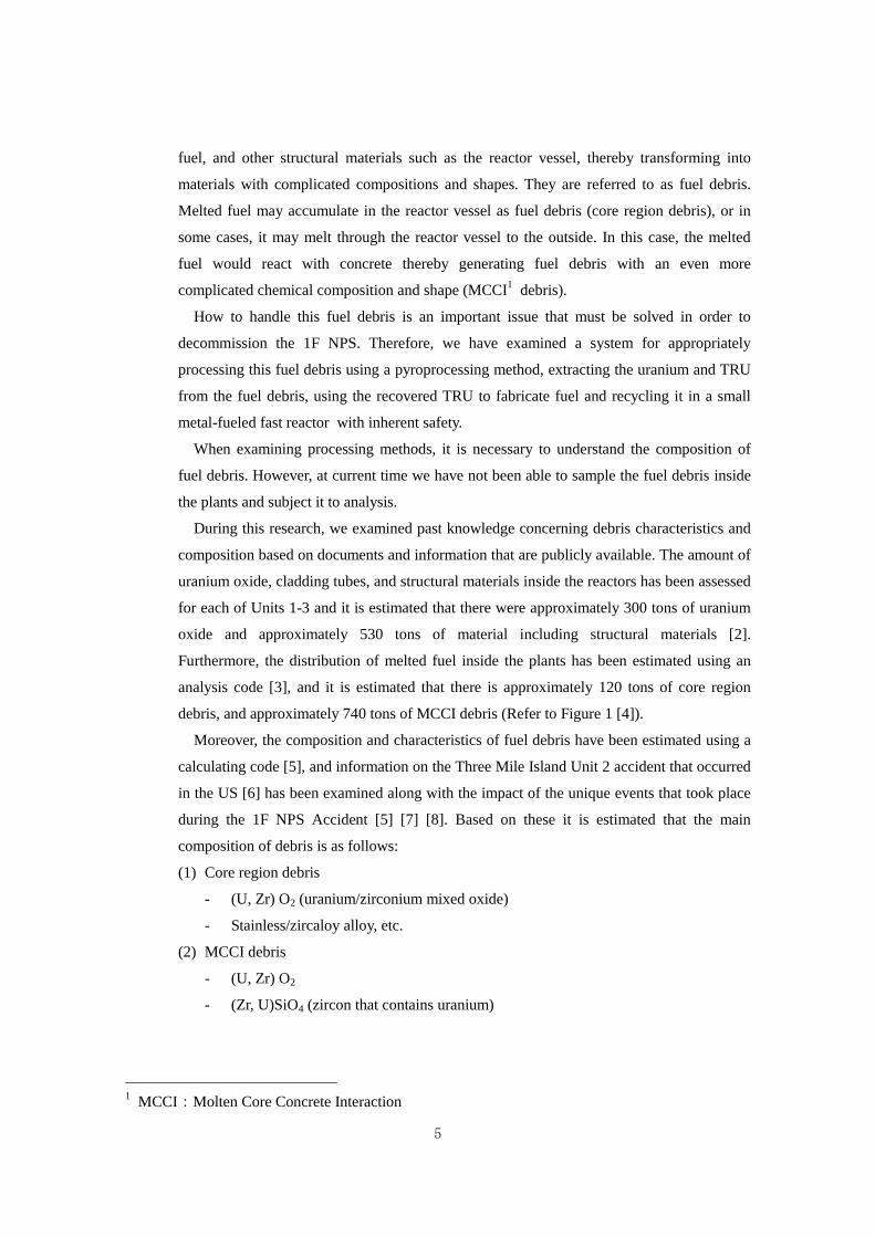
Furthermore, the distribution of melted fuel inside the plants has been estimated using an
analysis code [3], and it is estimated that there is approximately 120 tons of core region
debris, and approximately 740 tons of MCCI debris (Refer to Figure 1 [4]).
Moreover, the composition and characteristics of fuel debris have been estimated using a
calculating code [5], and information on the Three Mile Island Unit 2 accident that occurred
in the US [6] has been examined along with the impact of the unique events that took place
during the 1F NPS Accident [5] [7] [8]. Based on these it is estimated that the main
composition of debris is as follows:
(1) Core region debris
- (U, Zr) O2 (uranium/zirconium mixed oxide)
- Stainless/zircaloy alloy, etc.
(2) MCCI debris
- (U, Zr) O2
- (Zr, U)SiO4 (zircon that contains uranium)
1 MCCI:Molten Core Concrete Interaction
6
- CaAl2Si2O8 (anorthite; primary rock forming mineral of basic igneous rock), etc.
2.2 Fuel Debris Processing Scheme using a Sodium-Cooled Small Metal-Fueled Fast Reactor
(small MF-SFR) and a Pyroprocessing System
The mass of the nuclear material at the 1F NPS, and a breakdown of this material, was
calculated based on publicly released reports [9] from JAEA. In the present research, it was
assumed that the plant would be decommissioned within 40 years after the accident. As the
average fuel composition for debris in Units 1-3, we used the composition at the time of the
largest number of years since the disaster when the content of MA becomes maximum and
makes void reactivity severe. Under these conditions the amount of TRU and heavy metals
was found to be 1.94 tons and 251 tons, respectively.
The debris contains fuel elements such as plutonium and the aforementioned MA, which
are contained in the spent fuel of light water reactors (LWRs). Since these TRU can be
burned with good efficiency in a fast reactor, the amount of TRU can be decreased by
charging the core with TRU and burning them in the fast reactor. By extracting TRU from
this spent fuel, fabricating fuel and burning it in the fast reactor repeatedly, the long-term
radiotoxicity of high-level radioactive waste produced from the spent fuel can be ultimately
decreased.
We then determined the fuel debris burn-up scheme and the scale of output of the fast
reactor as follows assuming that TRU contained in this debris will be burned in a MF-SFR.
1) The proposal contains two steps; the burning of TRU in the debris in a small MF-SFR
(Step 1), and the reduction of the mass of TRU by recycling the TRU during the
lifespan of the plant (Step 2).
Fig.1 Assumed states of the Unit 1-3 cores/containment vessels [3].
7
2) The amount of time required to process all of the nuclear fuel in the fuel debris into fuel
assemblies is assumed to be 15 years, by considering the decommissioning plan of the
1F NPS.
3) It is assumed that TRU nuclear conversion performances (fuel mass, TRU burn-up
speed) per unit output of the small MF-SFR are the same as that of the GEH PRISM
TRU burning reactor with the thermal output of 840MWt (electrical output: 311MWe)
[10] being examined. In other words, refueling would be done a quarter of the reactor at
a time, resulting in a four-batch reactor. The cycle length, which is the refueling interval,
would be one year. The out-pile residence time of spent fuel (shortest fuel-cooling
period) would be two years [11].
4) As a result, if 1.94 tons of TRU extracted from debris could be used as fuel for 15 years,
the thermal output of the small MF-SFR would be 190MWt (electrical output: 70MWe).
In order to make this scheme feasible, fuel cycle facilities would be necessary in addition
to the reactor. This research examines the technical feasibility of applying the concept of
IFR that integrates a fast reactor with a fuel cycle in order to process fuel debris and reduce
the amount of TRU. The facility at ANL in the US [12] shown in Figure 2 is a typical
example of what this facility would look like.
Fig. 2 Concept diagram of an IFR
that combines a fast reactor with
a fuel recycling facility.
(Example: ANL Experimental
Breeder Reactor EBR-II and Fuel
Cycle Facility (FCF) [12])
8
Figure 3 shows how the debris will be converted into fuel and the fast reactor operating
plan. In [I] the debris is processed and the initial loading fuel for the fast reactor is
fabricated. In [II] while the debris is being processed and the fuel fabricated, the reactor is in
operation and producing spent fuel. This continues until all the debris is gone. [I] and [II] in
the diagram represent Step 1. After the debris is gone, the spent fuel is processed and
recycled [III], or in other words, Step 2 begins.
Figure 4 shows how the amount of TRU would decrease through these actions. An
evaluation of material balance of heavy metals and TRU in this debris processing/burn-up
scheme was performed based on the TRU burn-up characteristics determined by the core
conceptual design for the 190MWt reactor, which will be discussed later. As a result, we
found out that initial charging fuel can be produced in four years prior to launching the
reactor and all debris would be processed in six years after launching the reactor, or in other
words, it would take only 10 years to complete Step 1 instead of the originally estimated 15
years. The 1.9 tons of TRU present in the debris would be reduced to a total of 1.2 tons in
25 years after launching the fast reactor cycle with approximately 0.8 tons remaining in the
reactor and approximately 0.4 tons existing in the spent fuel, which indicates that TRU in
the debris can be transformed into well controlled states in the fuel assemblies.
Fig. 3 Concept diagram of debris
processing scheme.
Fig. 4 IFR operation and TRU reduction.
9
The spent fuel burned in the reactor will be subject to reprocessing after it has been
sufficiently cooled in a sodium pool for a certain amount of time (envisioned to be 16
months in this research) and used for fuel fabrication. When it is time to refuel in 24.7 years
after the commencement of operation, this spent fuel that has been cooled for more than 16
months will be used up, so there will not be enough spent fuel to be reprocessed and to be
fabricated into fuel for continual operation of the fast reactor. After the cooling period of 16
months, TRU will be extracted from the spent fuel and used for one more cycle (eight
months) thereby enabling the reactor to be operated for 25.3 years after the commencement
of operation. However, after this it will not be possible to continually operate the reactor.
Rather, operation of the reactor will be intermittent as spent fuel is reprocessed and used to
fabricate fuel after the cooling periods, and then used to load the reactor.
There are two options for handling operation after 25.3 years.
(1) Shutdown this reactor after 25.3 years of operation and reprocess the remaining spent
fuel to use it as new fuel in a different fast reactor.
(2) Continue to operate this reactor even after 25.3 years by supplying TRU from other
LWRs, etc.
[※It may be possible to treat 2,724* spent fuel assemblies stored in Unit 1 through 4 of
TEPCO 1F NPS. (* Breakdown: 292 assemblies in Unit 1, 587 in Unit 2, 514 in
Unit 3 and 1,331 in Unit 4. Assemblies in Unit 4 were already removed from the
spent fuel pool by December 22, 2014.)]
Operating the reactor in this way is an option, and Figure 4 shows the changes in the
amount of TRU during the first 25.3 years when continuous operation of the reactor is
possible.
10
2.3 Pyroprocessing System Concept
A system that combines pyroprocessing (metal electrolysis) based on molten salt
electrolysis with fuel fabrication technology based on injection casting (molding) has been
developed and can be utilized with the MF-SFR. However, as indicated in Section 2.1, since
the fuel debris primarily consists of oxides which differ from normal oxide fuel, a technical
method for processing the debris appropriately and readying it for metal electrolysis is
necessary.
Publicly available documents were focused on to investigate approximately 10 different
types of technologies for processing debris that has the composition estimated in Section 2.1.
A general assessment of these technologies was made from the perspectives of (1)
dissolution (reduction) separation potential, (2) uranium, plutonium and MA co-recovery
potential, (3) compatibility with metallic fuel fabrication, and as a secondary criterion (4)
amount of waste generated. Firstly, (1) was used to narrow down the candidate processes.
Thereafter (2) and (3) were considered and ultimately a process that uses electrolytic
reduction was selected. Two methods of electrolytic reduction were envisioned; reduction in
lithium chloride, and reduction in calcium chloride. There are issues with both these
methods that require more R&D, however it is considered beneficial to continue the
development of electrolytic reduction and succeeding electrorefining both in lithium
chloride salt, a method for which there is plenty of knowledge that can be utilized. Figure 5
shows a concept drawing of the pyroprocessing technology.
Fig. 5 Pyroprocessing technology (for oxide and metallic fuels).
11
Figure 6 is a simple flow diagram showing pyroprocessing, the fuel fabrication process
and the flow of nuclear material. In order to fabricate the initial loading fuel in four years
based on this debris processing scheme, 30 tons will have to be processed annually on a
heavy metal (fuel) basis. After the debris is pulverized during preprocessing, it is subject to
electrolytic reduction and the reduced material is provided to the next step, which is the
electrolytic refining process. This is where the uranium and uranium + TRU to be used as
the raw materials for fuel fabrication are recovered individually.
The material remaining on the anode during the electrolytic refining process will be
processed to recover uranium and the residue will be disposed of as waste. Furthermore, the
salt from the electrorefining process will be recycled and the fission products (FP) will be
disposed of as solid minerals. During fuel fabrication, a portion of the recovered fuel will be
mixed in with suitable percentages of uranium and TRU to make fuel rods by a method
called injection casting after which it will be used to load the reactor. Annual throughput of
fuel fabrication will be 0.72 tons.
Most of the recovered uranium will be stored.
The waste generated by the aforementioned process will be geologically disposed of after
it is processed using stable solidification processing technology that has been developed as
part of the normal metallic fuel cycle. In particular, molten salt waste will be processed into
a mineral solid called sodalite and disposed of as high-level radioactive waste, and the metal
waste remaining on the anode will be solidified using cement and disposed of as TRU
Fig. 6 Material balance and system configuration (in the case of core region debris).
12
waste.
During the first 10 years when debris is being processed the annual throughput of
reprocessing will be 30 tons, but will drop to approximately 1 ton per year thereafter.
2.4 Small MF-SFR concept
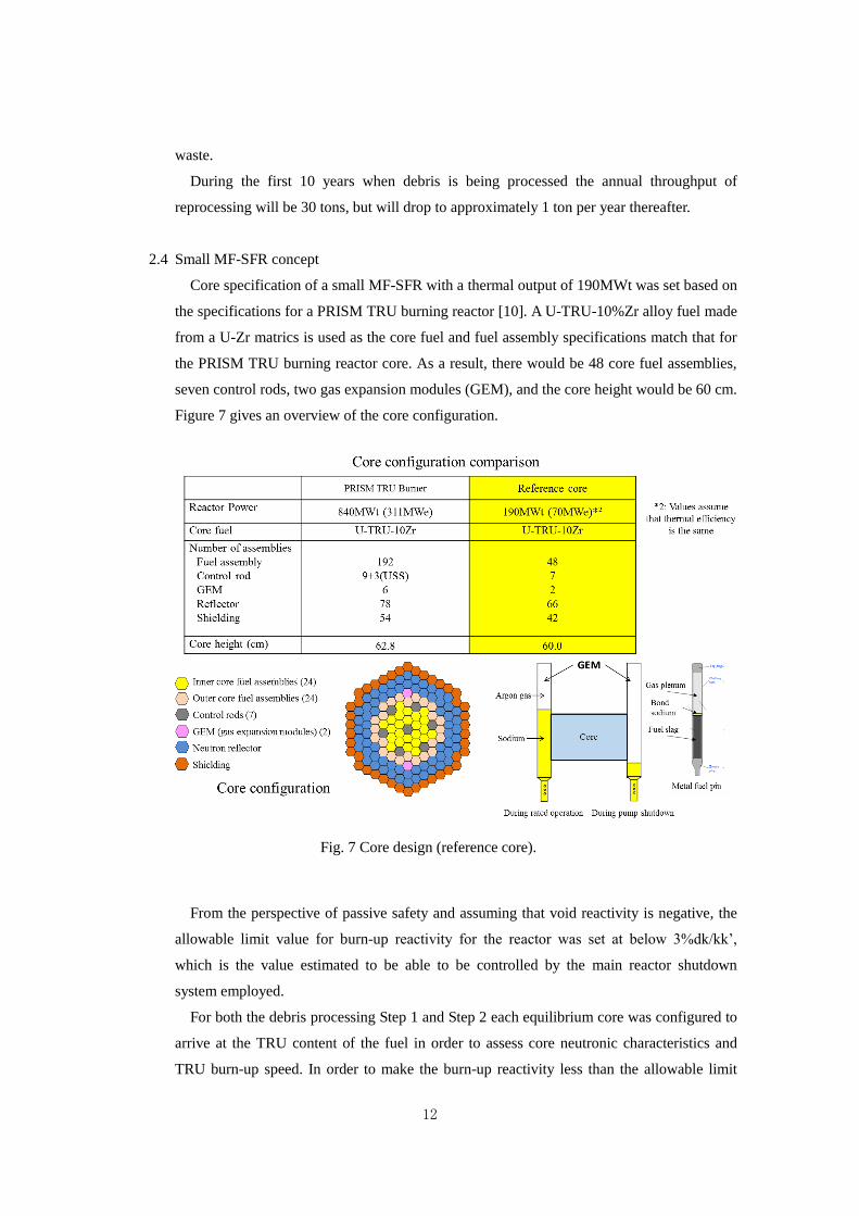
Core specification of a small MF-SFR with a thermal output of 190MWt was set based on
the specifications for a PRISM TRU burning reactor [10]. A U-TRU-10%Zr alloy fuel made
from a U-Zr matrics is used as the core fuel and fuel assembly specifications match that for
the PRISM TRU burning reactor core. As a result, there would be 48 core fuel assemblies,
seven control rods, two gas expansion modules (GEM), and the core height would be 60 cm.
Figure 7 gives an overview of the core configuration.
From the perspective of passive safety and assuming that void reactivity is negative, the
allowable limit value for burn-up reactivity for the reactor was set at below 3%dk/kk’,
which is the value estimated to be able to be controlled by the main reactor shutdown
system employed.
For both the debris processing Step 1 and Step 2 each equilibrium core was configured to
arrive at the TRU content of the fuel in order to assess core neutronic characteristics and
TRU burn-up speed. In order to make the burn-up reactivity less than the allowable limit
Fig. 7 Core design (reference core).
13
value an 8-month operation x 6 batch refueling, by which 1/6 of the fuel in the core will be
refueled every eight months of operation, was employed.
As a result, TRU content (TRU percentage) in the outer core was 35.1%
(U-35.1%TRU-10%Zr). The TRU content of this core exceeds development and testing
performance in the US. Burn-up reactivity fell below allowable limit values for both Step 1
and 2, and the net void reactivity, which corresponds to the total of the core region and the
upper gas plenum, was negative for both Steps 1 and 2 thereby satisfying design conditions
for both. The variation with time for the amount of TRU assessed from the TRU burn-up
speed obtained in this manner is shown in Figure 4.
2.5 Small MF-SFR Safety
2.5.1 Passive Reactor Shutdown Capability
When designing reactor safety, “anticipated transients” and “design basis
accidents” are considered in accordance with the frequency of occurrence of
various abnormalities that are predicted to occur during the plant life. In the event
of one of these abnormalities, engineered safety systems such as the reactor
shutdown system and the decay heat removal system “shutdown” and “cool-down”
the reactor safely. Therefore the reactor is designed and assessed so that the
integrity of the reactor fuel is maintained and radioactive materials will not
discharged to the environment.
After the Three Mile Island accident in 1979, the most of the countries carried
out probabilistic safety assessments and launched the research on passive safety,
which means to prevent the core damage by leading abnormal reactor conditions to
safe conditions by both the passive shutdown and passive cooling using the laws of
natural phenomena. Here no detection system and no power source will be
required like the engineered safety features. These passive safety features should
be effective against not only design basis accidents but also extremely rare events
considered from the occurrence probability such as multiple failures of safety
systems. In conjunction with these efforts, the following investigations had been
facilitated such as core damage behaviors and counter-measures to mitigate the
release of the radioactive materials to the environment, even though there were less
knowledge in LWRs at that time.
On the other hand, the safety design and research for SFRs have been focused on
the hypothetical core disruptive accidents from the early era of its development, i.e.,
since the 1960s. In SFRs, core damage events progress quickly to increase the
re-criticality risk by propagating the core melt regions and the melt amounts, and
14
thus these events are referred to as core disruptive accidents. Even though a
certain level of re-criticality event may occur, the resultant mechanical energy due
to the vaporization of sodium, structural materials and fuels should have sufficient
design margin to contain together with cooling down the decay heat of fuel debris
within the reactor vessel. No significant consequences to challenge the
containment integrity would occur due to the core disruptive accidents. This
in-vessel retention capability has been the focal point of safety design and
evaluations for SFR so far. In the wake of the Three Mile Island Accident
investigation on passive safety for SFR was also carried out, and in particular, the
safety features of a small MF-SFR became known all over the world through the
demonstration tests using the EBR-II (thermal/electrical output:
62.5MWt/20MWe).
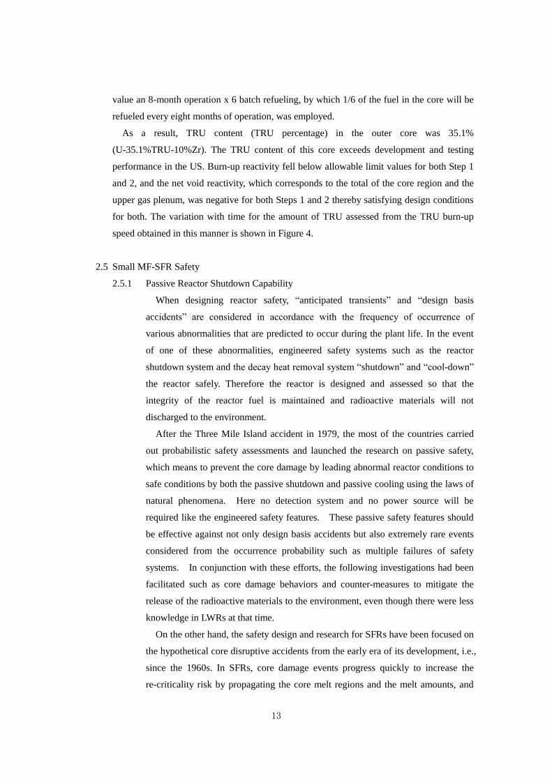
From May 1985 through April 1986 the EBR-II was used to conduct inherent
safety demonstration tests for small MF-SFR [13]. Examples of the results from
tests simulating an anticipated transient without scram (ATWS) are shown in Figure
8(a) ((1) Main pump trip from full power condition, i.e., unprotected loss-of-flow
(ULOF) and Figure 8(b) ((2) loss of secondary cooling system such as pump trip or
loss of feed water into steam generators from full power condition, i.e., Loss of heat
sink without scram (ULOHS). Both tests simulate events where main circulation
pumps trip as a result of a loss of external power and reactor scram fails. However
the former is a more serious event because the reactor core temperature increases
rapidly due to the flow coast down. With the latter, coolability becomes
insufficient due to the increase of the inlet coolant temperature as the result of the
decrease in the secondary coolant flow, thereby, relatively speaking, ULOHS will
not be so severe. However since there are so many abnormal possibility in the
secondary cooling system and the water-steam system leading to this event, the
frequency of occurrence becomes higher than the former.
In either case, any fuel pin failures were not occurred and the reactor shut down
was achieved safely. Since the EBR-II is approximately one third the size of the
reactor core considered in this study, the negative reactivity feedback from reactor
core, structural materials and coolant are larger enough to safely shutting down the
reactor and the coolant temperatures keeps equal to that of rated operating
conditions without a passive reactor shutdown mechanism.
15
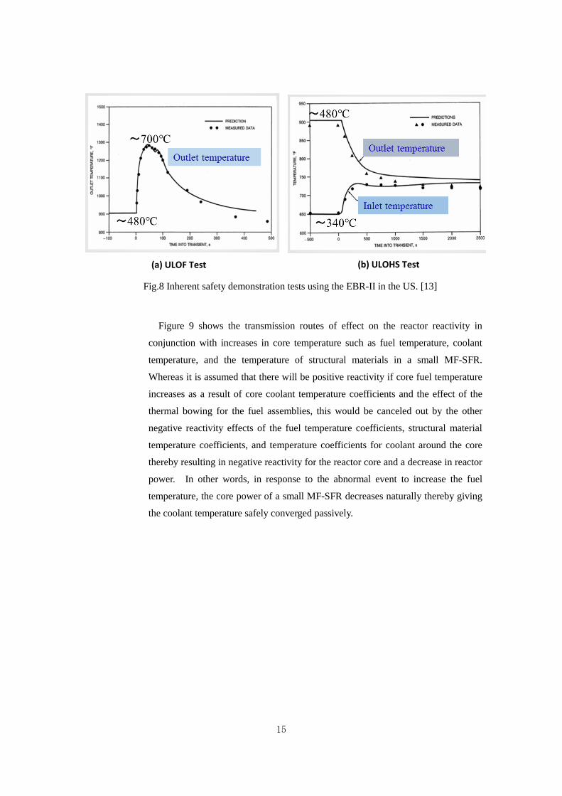
Figure 9 shows the transmission routes of effect on the reactor reactivity in
conjunction with increases in core temperature such as fuel temperature, coolant
temperature, and the temperature of structural materials in a small MF-SFR.
Whereas it is assumed that there will be positive reactivity if core fuel temperature
increases as a result of core coolant temperature coefficients and the effect of the
thermal bowing for the fuel assemblies, this would be canceled out by the other
negative reactivity effects of the fuel temperature coefficients, structural material
temperature coefficients, and temperature coefficients for coolant around the core
thereby resulting in negative reactivity for the reactor core and a decrease in reactor
power. In other words, in response to the abnormal event to increase the fuel
temperature, the core power of a small MF-SFR decreases naturally thereby giving
the coolant temperature safely converged passively.
(b) ULOHS Test
Fig.8 Inherent safety demonstration tests using the EBR-II in the US. [13]
(a) ULOF Test
16
During this deliberation, a passive reactor shutdown mechanism was employed
in order to do away with fears toward the uncertainties regarding events that would
result in passive safety and so that coolant temperature will be decreased safely.
In particular, in response to ULOF where all main circulation pumps trip due to a
loss of external power supply and the reactor failed the scram, the GEM located
around the core as shown in Fig. 7 would insert the negative reactivity by
enhancing the neutron leakage as the result of expansion of the gas region due to
the decrease in pump pressure in conjunction with pump trip. In response to
UTOP as a result of abnormal control rod withdrawal, the event could be brought
under control before the core was damaged by employing a rod stop mechanism
that limits the extent to which control rods can be withdrawn and controls the
amount of positive reactivity applied to the reactor.
Furthermore, at the TEPCO 1F NPS, although systems and equipment required
for ensuring safety were not damaged by the earthquake, the loss of external power
(station blackout) caused by the quake caused the main circulation pumps trip.
However, the reactors scrammed without problem and the decay heat removal
systems were functioning normally after being started with emergency power.
However, as a result of the enormous tsunami that hit the power station
approximately 50 minutes later all emergency power sources and DC power
sources such as batteries, were lost thereby making it impossible to ascertain the
open/closed status of valves required for decay heat removal and actually open and
close these valves. This coupled with the amount of time required to inject water
into the reactor to cool the core (including the injection of seawater) were the
Fig.9 Passive safety of small metal-fueled reactors.
17
factors that led to the large-scale core meltdowns.
Since fast reactors will also be designed and manufactured to withstand against
strong earthquakes, much like with LWRs, it is impossible that safety function
would be lost as a result of a similar earthquake. And, even if all power sources
were lost as the result of a tsunami, since the decay heat removal systems of a fast
reactor are simple consisting only of naturally circulating sodium and releasing the
heat into the atmosphere and not requiring any special actions to inject the sodium
coolant, the amount of heat removed can be controlled at a specific level by
manually operating air coolers without the need for DC power. In other words, the
decay heat removal system of a SFR that does not require intentional coolant
injection, which was the most important issue when the 1F NPS accident occurred,
can greatly reduce the possibility of core damage.
2.5.2 Mitigation of Core Damage Consequences
Due to the passive safety features of a small MF-SFR core, the frequency of the
core damage will be decreased, however, it is necessary to indicate how the
consequence of core damage can be mitigated and how the possibility of the release
of radioactive materials can be mitigated. Therefore, during this study we
considered a case where the effect of the passive reactor shutdown mechanism was
ignored and also considered various uncertainties envisioned as events progress and
examined how core damage events would progress from the ATWS such as the
aforementioned ULOF, UTOP and ULOHS in consideration of safety features of a
small MF-SFR core. In a ULOHS event the core is not damaged, just like the
response in the EBR-II as shown in Figure 8. In a ULOF event, the response is
larger than that of the EBR-II due to the large scale of reactor power and the fuel
cladding tube poses a potential risk of rupture, however there is no significant core
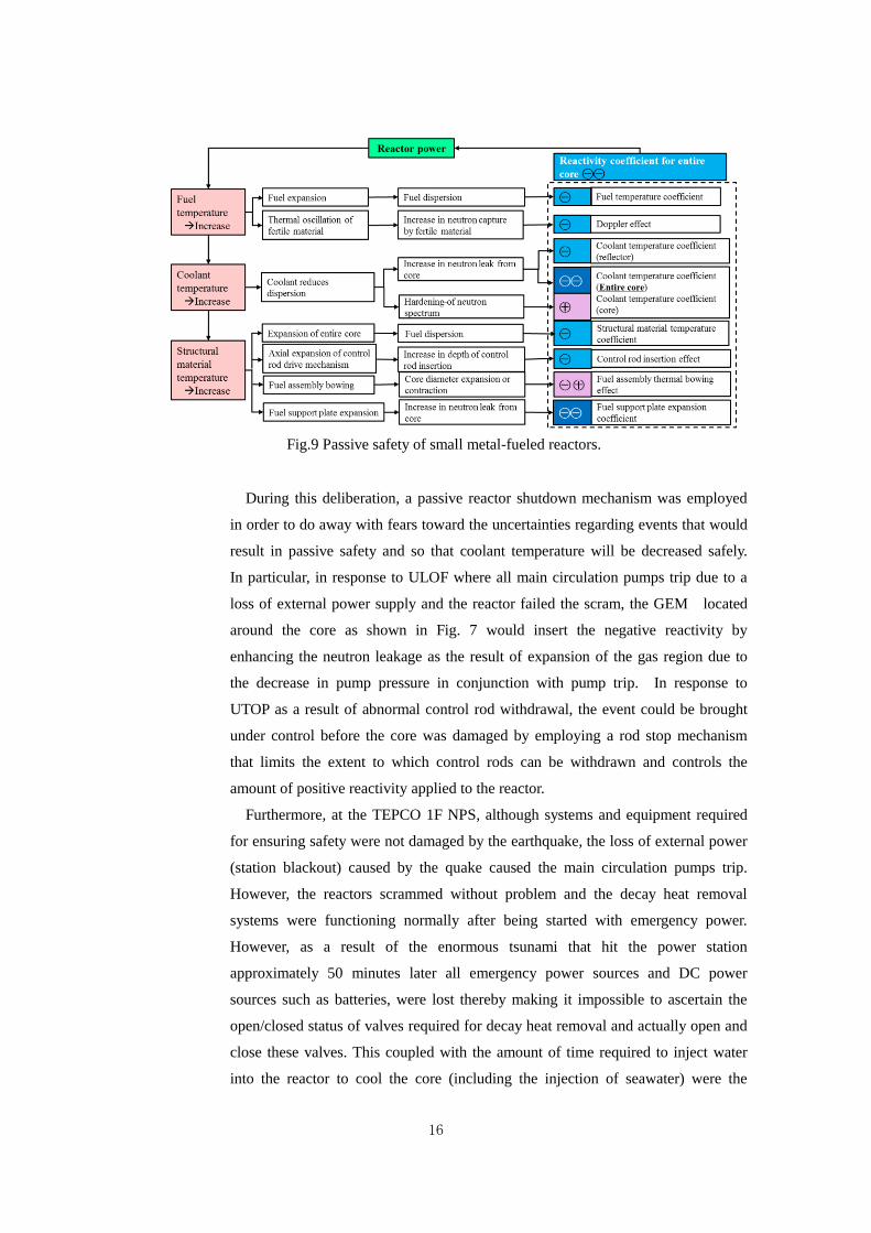
melting and the release of mechanical energy can be limited. In a UTOP event
caused by abnormal control rod withdrawal, if we ignore the effect of the passive
scram mechanism (rod stop), reactor power increases, the cladding tube ruptures
and molten fuel is discharged into the coolant (Refer to Figure 10). However, it is
expected that since metallic fuel pin failures occur at the top of the core, the molten
fuel discharged into the coolant channel around the outside of the core thereby
causing a negative reactivity effect that terminates the event without causing the
re-criticality leading to the release of a large scale mechanical energy.
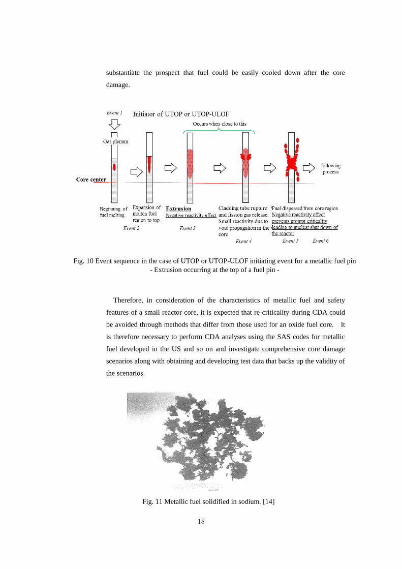
Experimental test results that show that molten metallic fuel that has come in
contact with/mixed with coolant becomes porous debris (Refer to Figure 11)
18
substantiate the prospect that fuel could be easily cooled down after the core
damage.
Therefore, in consideration of the characteristics of metallic fuel and safety
features of a small reactor core, it is expected that re-criticality during CDA could
be avoided through methods that differ from those used for an oxide fuel core. It
is therefore necessary to perform CDA analyses using the SAS codes for metallic
fuel developed in the US and so on and investigate comprehensive core damage
scenarios along with obtaining and developing test data that backs up the validity of
the scenarios.
Fig. 10 Event sequence in the case of UTOP or UTOP-ULOF initiating event for a metallic fuel pin
- Extrusion occurring at the top of a fuel pin -
Fig. 11 Metallic fuel solidified in sodium. [14]
19
2.6 Effect of Reducing the Volume of Radioactive Waste and Decreasing the Radiotoxicity
(Hazard Level)
The International Commission on Radiological Protection (ICRP) defined an annual limit
on intake for each radionuclide in consideration of the risk of radiation exposure to the
human body by ingestion. Radiotoxicity is the radioactivity of a nuclide (including the
daughter and grand-daughter nuclides of decay series) included in spent fuel discharged
from a reactor or radioactive waste generated from the reprocessing of spent fuel divided by
the annual intake limit.
Fuel debris is similar to ordinary LWR spent fuel in terms of radiotoxicity. Therefore,
along with reducing TRU by suitably processing fuel debris and recycling it in a fast reactor,
a transition can be made to well-managed conditions where TRU is either kept in the core or
as part of spent fuel.
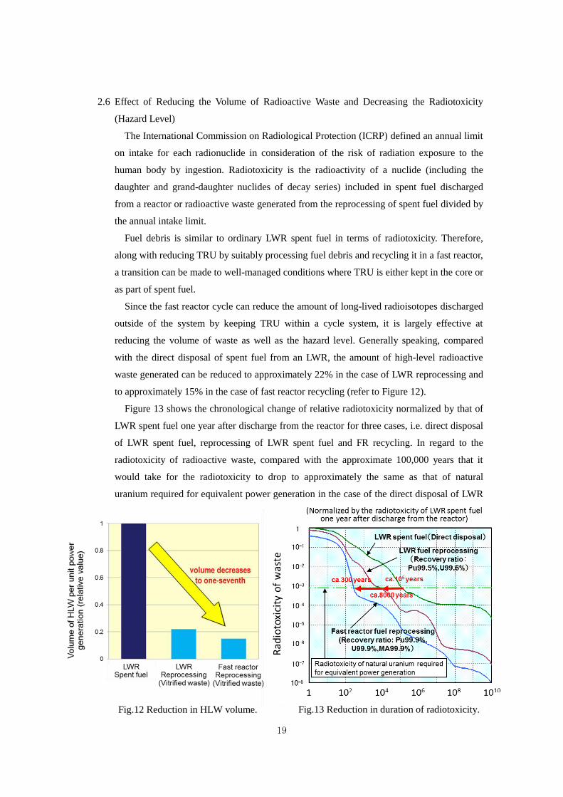
Since the fast reactor cycle can reduce the amount of long-lived radioisotopes discharged
outside of the system by keeping TRU within a cycle system, it is largely effective at
reducing the volume of waste as well as the hazard level. Generally speaking, compared
with the direct disposal of spent fuel from an LWR, the amount of high-level radioactive
waste generated can be reduced to approximately 22% in the case of LWR reprocessing and
to approximately 15% in the case of fast reactor recycling (refer to Figure 12).
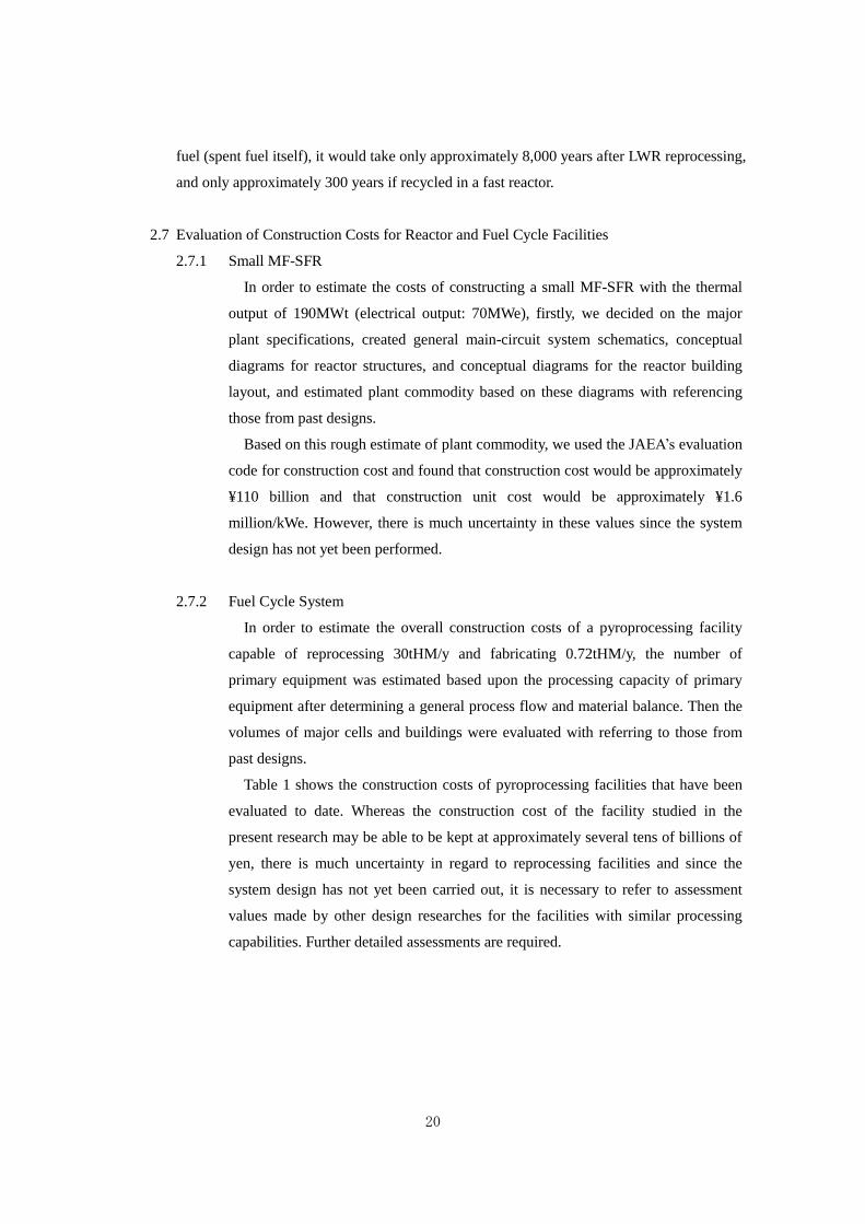
Figure 13 shows the chronological change of relative radiotoxicity normalized by that of
LWR spent fuel one year after discharge from the reactor for three cases, i.e. direct disposal
of LWR spent fuel, reprocessing of LWR spent fuel and FR recycling. In regard to the
radiotoxicity of radioactive waste, compared with the approximate 100,000 years that it
would take for the radiotoxicity to drop to approximately the same as that of natural
uranium required for equivalent power generation in the case of the direct disposal of LWR
Fig.12 Reduction in HLW volume. Fig.13 Reduction in duration of radiotoxicity.
20
fuel (spent fuel itself), it would take only approximately 8,000 years after LWR reprocessing,
and only approximately 300 years if recycled in a fast reactor.
2.7 Evaluation of Construction Costs for Reactor and Fuel Cycle Facilities
2.7.1 Small MF-SFR
In order to estimate the costs of constructing a small MF-SFR with the thermal
output of 190MWt (electrical output: 70MWe), firstly, we decided on the major
plant specifications, created general main-circuit system schematics, conceptual
diagrams for reactor structures, and conceptual diagrams for the reactor building
layout, and estimated plant commodity based on these diagrams with referencing
those from past designs.
Based on this rough estimate of plant commodity, we used the JAEA’s evaluation
code for construction cost and found that construction cost would be approximately
¥110 billion and that construction unit cost would be approximately ¥1.6
million/kWe. However, there is much uncertainty in these values since the system
design has not yet been performed.
2.7.2 Fuel Cycle System
In order to estimate the overall construction costs of a pyroprocessing facility
capable of reprocessing 30tHM/y and fabricating 0.72tHM/y, the number of
primary equipment was estimated based upon the processing capacity of primary
equipment after determining a general process flow and material balance. Then the
volumes of major cells and buildings were evaluated with referring to those from
past designs.
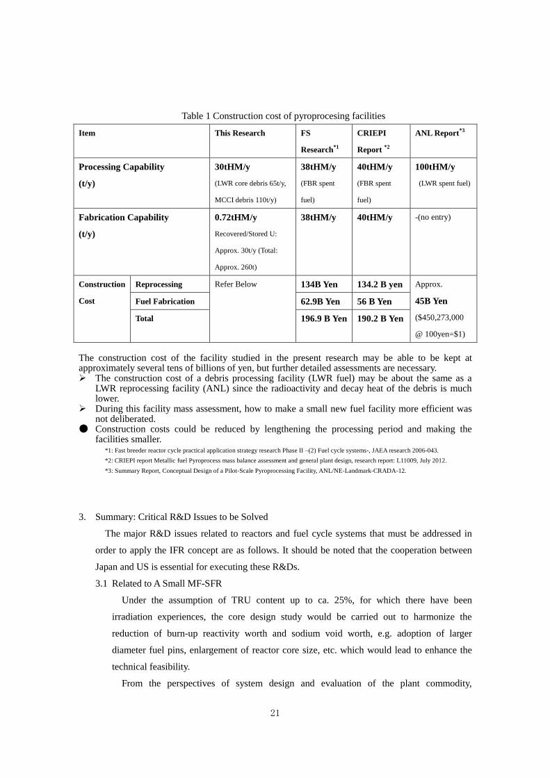
Table 1 shows the construction costs of pyroprocessing facilities that have been
evaluated to date. Whereas the construction cost of the facility studied in the
present research may be able to be kept at approximately several tens of billions of
yen, there is much uncertainty in regard to reprocessing facilities and since the
system design has not yet been carried out, it is necessary to refer to assessment
values made by other design researches for the facilities with similar processing
capabilities. Further detailed assessments are required.
21
Table 1 Construction cost of pyroprocesing facilities
Item This Research FS
Research*1
CRIEPI
Report *2
ANL Report*3
Processing Capability
(t/y)
30tHM/y
(LWR core debris 65t/y,
MCCI debris 110t/y)
38tHM/y
(FBR spent
fuel)
40tHM/y
(FBR spent
fuel)
100tHM/y
(LWR spent fuel)
Fabrication Capability
(t/y)
0.72tHM/y
Recovered/Stored U:
Approx. 30t/y (Total:
Approx. 260t)
38tHM/y 40tHM/y -(no entry)
Construction
Cost
Reprocessing Refer Below 134B Yen 134.2 B yen Approx.
45B Yen
($450,273,000
@ 100yen=$1)
Fuel Fabrication 62.9B Yen 56 B Yen
Total 196.9 B Yen 190.2 B Yen
The construction cost of the facility studied in the present research may be able to be kept at approximately several tens of billions of yen, but further detailed assessments are necessary. The construction cost of a debris processing facility (LWR fuel) may be about the same as a
LWR reprocessing facility (ANL) since the radioactivity and decay heat of the debris is much lower.
During this facility mass assessment, how to make a small new fuel facility more efficient was not deliberated.
● Construction costs could be reduced by lengthening the processing period and making the facilities smaller.
*1: Fast breeder reactor cycle practical application strategy research Phase II –(2) Fuel cycle systems-, JAEA research 2006-043.
*2: CRIEPI report Metallic fuel Pyroprocess mass balance assessment and general plant design, research report: L11009, July 2012.
*3: Summary Report, Conceptual Design of a Pilot-Scale Pyroprocessing Facility, ANL/NE-Landmark-CRADA-12.
3. Summary: Critical R&D Issues to be Solved
The major R&D issues related to reactors and fuel cycle systems that must be addressed in
order to apply the IFR concept are as follows. It should be noted that the cooperation between
Japan and US is essential for executing these R&Ds.
3.1 Related to A Small MF-SFR
Under the assumption of TRU content up to ca. 25%, for which there have been
irradiation experiences, the core design study would be carried out to harmonize the
reduction of burn-up reactivity worth and sodium void worth, e.g. adoption of larger
diameter fuel pins, enlargement of reactor core size, etc. which would lead to enhance the
technical feasibility.
From the perspectives of system design and evaluation of the plant commodity,
22
achieving system design of the whole plant, thermal-hydraulic analyses, structural integrity
evaluations, performance evaluation of decay heat removal systems such as the reactor
vessel auxiliary cooling system (RVACS), and evaluation of seismic capability are vital for
assessing technical feasibility and construction costs.
Furthermore, in regard to safety evaluation and experiments, with taking account of
safety characteristics of a small MF-SFR and obtained experimental data so far, (1) passive
shut down and passive decay heat removal would be achieved against ATWS, which are
addressed as beyond design bases accidents, and (2) re-criticality free core concept would
be pursued by adopting an appropriate design measure to prevent molten fuel compaction.
Then the resultant mitigated CDA sequence would be validated by in-pile and out-pile
experiments, are crucial to obtain a perspective for licensing.
3.2 Related to Pyroprocessing Systems
In regard to the pyroprocessing system, in order to process debris that has a different
composition from ordinary fuel, it is necessary to examine the following issues concerning a
lithium (Li) salt electrolytic reduction/electrorefining process.
- Examination of methods for separating reduced fuel elements from generated Li/Zr
complex oxides,
- Examination of the behavior of these complex oxides when brought into the
electrorefining process and methods for handling,
- Ascertaining the reduction behavior of fuel debris,
- Ascertaining the behavior of silicon, zirconium, aluminum, iron, etc. during the
electrorefining process of MCCI debris that has reacted with concrete and
developing effective pretreatment techniques,
- Ascertaining the handling of hygroscopic lithium salt by taking into account of
debris being soaked in water.
It is important to examine the following in regard to calcium (Ca) reduction as an
alternative when it is revealed that there are too many technical issues with Li reduction.
- Ascertaining (electrolytic) reduction behavior,
- Examining the integrity of structural materials during high temperature operation
(approximately 850 ℃).
END
23
References
[1] Research and Development Bureau, MEXT, “Policy on the research and development of fast
breeder reactor cycles”, Nov. 2, 2006 (in Japanese),