5
Digital & Analog Partyline Intercom Cabling Comparison Technical Guide

Digital & Analog Partyline Intercom Cabling Comparison
Technical Guide
Technical Guide |
Digital & Analog Partyline Intercom Cabling Comparison Page 2
Overview Digital partyline intercom products offer some significant feature and performance advantages over analog partyline intercom products and in most cases using the same cable types. This document provides a comparison of the demands
placed on a cable by both analog and digital partyline intercom products. The goal of this technical guide is to provide readers with a clear understanding of the cable characteristics
important to the performance of partyline intercom systems. It also explains the operation of the online
Clear-Com digital partyline cable calculator:
Digital Partyline Calculator
Background Each cable type has a number of physical and electrical characteristics that affect its suitability for an application. Among these are:
Number of cores Core twist properties Shielding
Overall diameter Flexibility Voltage rating Flammability rating
The electrical characteristics that are of particular interest for those transitioning from analog to digital partyline systems are:
DC resistance Signal attenuation
Introduction In both analog partyline systems, which have been in
use since the 1960s, and more recently introduced digital partyline systems, standard 3-pin mic cable is used between a main station and beltpack to carry two things:
Power Data (Audio and Control)
Power Limits The one factor that affects a cable’s ability to deliver DC
power is its DC resistance which is related to its gauge. Figure 1 shows the relationship between cable gauge and DC resistance.
Figure 1 Cable DC Resistance vs Wire Gauge
The larger the cable (lower gauge number), the lower the DC resistance and the better its ability to deliver power over a longer distance. Here are some examples for both analog and digital partyline.
Analog Partyline In an analog partyline system, the master station delivers around 30V DC to the line. The beltpack requires a minimum voltage of around 12 to 20V DC (varies dependent on type) at its input in order to operate. Most analog beltpacks draw the same current
(around 25mA) from the line no matter what voltage
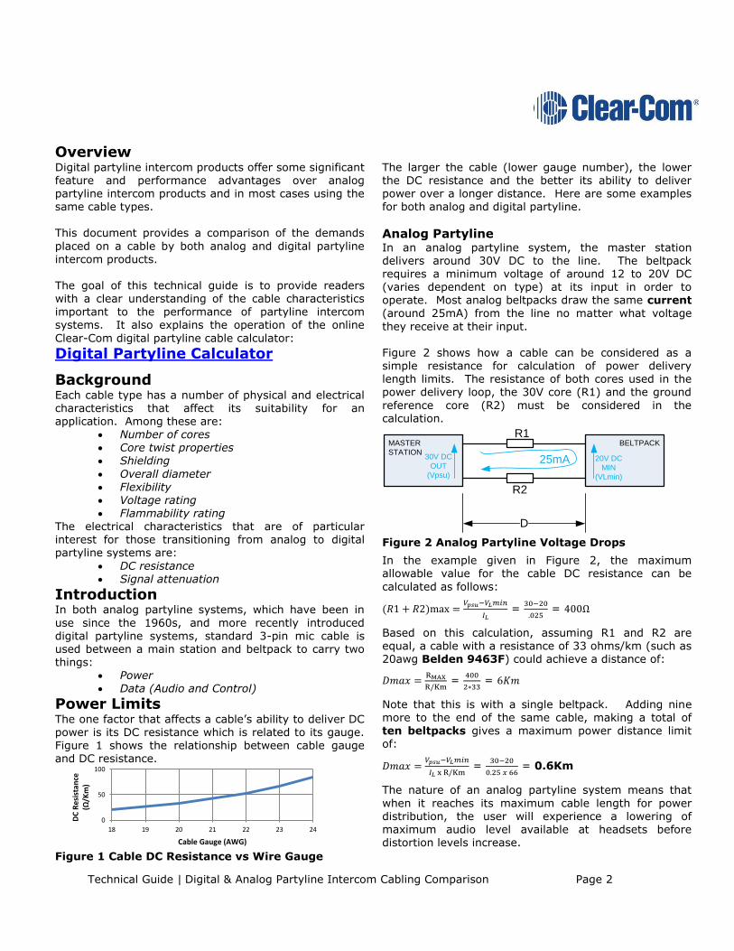
they receive at their input. Figure 2 shows how a cable can be considered as a simple resistance for calculation of power delivery length limits. The resistance of both cores used in the power delivery loop, the 30V core (R1) and the ground
reference core (R2) must be considered in the calculation.
MASTER
STATION
BELTPACKR1
R2
25mA30V DC
OUT
(Vpsu)
20V DC
MIN
(VLmin)
D
Figure 2 Analog Partyline Voltage Drops
In the example given in Figure 2, the maximum allowable value for the cable DC resistance can be
calculated as follows:
(𝑅1 + 𝑅2)max =𝑉𝑝𝑠𝑢−𝑉𝐿𝑚𝑖𝑛
𝐼𝐿 =
30−20
.025 = 400Ω
Based on this calculation, assuming R1 and R2 are equal, a cable with a resistance of 33 ohms/km (such as 20awg Belden 9463F) could achieve a distance of:
𝐷𝑚𝑎𝑥 =RMAX
R/Km =
400
2∗33 = 6𝐾𝑚
Note that this is with a single beltpack. Adding nine more to the end of the same cable, making a total of
ten beltpacks gives a maximum power distance limit of:
𝐷𝑚𝑎𝑥 =𝑉𝑝𝑠𝑢−𝑉𝐿𝑚𝑖𝑛
𝐼𝐿 x R/Km =
30−20
0.25 𝑥 66 = 0.6Km
The nature of an analog partyline system means that
when it reaches its maximum cable length for power distribution, the user will experience a lowering of maximum audio level available at headsets before distortion levels increase.
0
50
100
18 19 20 21 22 23 24
DC
Res
ista
nce
(Ω/Km)
Cable Gauge (AWG)

Technical Guide |
Digital & Analog Partyline Intercom Cabling Comparison Page 3
Digital Partyline In a Clear-com digital partyline system, the master
station delivers around 59V DC to the line. The beltpack requires a minimum of around 24V DC in order to operate. Clear-Com digital partyline beltpacks take the same amount of power (around 3.5W) from the line no matter what voltage (within a specified range) they receive at their input.
MASTER
STATION
BELTPACKR1
R2
IL60V
DC
OUT
24V
DC
MIN
3.5W
LOAD
Figure 3 Digital Partyline Voltage Drop
This means that the calculation of maximum cable length is different to that for an analog beltpack. First it is necessary to calculate the current (IL) that would flow in the circuit with the lowest acceptable voltage (𝑉𝐿)
available at the load:
𝐼𝐿𝑚𝑎𝑥 =𝑃𝐿
𝑉𝐿
𝐼𝐿𝑚𝑎𝑥 = 3.5
24 = 146 𝑚𝐴
then calculate the maximum resistance:
𝑅1 + 𝑅2 =𝑉𝑝𝑠𝑢−𝑉𝐿(𝑚𝑖𝑛)
𝐼𝐿
𝑅1 + 𝑅2 = 59−24
.146 = 240Ω
and maximum distance allowed as before:
𝐷𝑚𝑎𝑥 =RMAX
R/Km
𝐷𝑚𝑎𝑥 = 240
2 x 33 = 3.6𝐾𝑚
Again, if the number of units at the end of the line increases from one to ten beltpacks, the maximum cable length allowable (with Belden 9463F) drops to:
𝐷𝑚𝑎𝑥 =𝑉𝑝𝑠𝑢−𝑉𝐿𝑚𝑖𝑛
(𝑃𝐿𝑉𝐿
) x R/Km
𝐷𝑚𝑎𝑥= 59−24
(35
24) x 66
= 0.36Km
The nature of Clear-Com’s digital partyline system means that when it reaches its maximum cable length for power distribution, units towards the end of the line will cease to operate until the cable connecting them to
their main station is brought back within the required specification.
Data Limits In addition to delivering power, in both analog and digital party line systems it is also necessary to ensure that the required data signal can be passed from source to destination.
Figure 4 Comparison of Cable Attenuation
As shown in Figure 4, the attenuation of a cable over a given distance increases as transmission frequency increases. Figure 4 also shows us that some cable types are designed to be more suitable for transmitting higher frequency data whilst other cable types are
designed to be suitable for lower frequency transmission.
Analog Partyline In analog party line, the maximum data frequency of
interest is the analog audio signal, a frequency of less
than 20 KHz. Figure 4 shows us that at frequencies below 1 MHz, all of the cable choices shown have a very low attenuation (<30dB/Km). The nature of the analog partyline system is also such that as cable attenuation between nodes increases, the effect observed by the user is a decrease in audio level
heard at the headset with a low distortion audio signal still being received. Take our previous analog partyline system as an example:
BELTPACK 10
BELTPACK 2
MASTER
STATION
BELTPACK 1
250mA30V
DC
OUT
20V
DC
MIN
0.6KmBelden 9463F
20Ω
20Ω
Figure 5 Ten Beltpack Analog Partyline Example
0
50
100
150
200
250
300
350
1 10 100
Att
en
uati
on
(d
B/K
m)
Frequency (MHz)
1813A1800F841292079463F
Belden Cable Part Numbers
Technical Guide |
Digital & Analog Partyline Intercom Cabling Comparison Page 4
In this extreme case, assume the audio signal is 20 KHz and the cable attenuation at 20 KHz is the same as at 1MHz (In reality it will be much lower, but cable
manufacturers do not specify cable attenuation at such low frequencies). There will be attenuation (see Figure 4) of around 30dB/Km so with our maximum allowable cable length the audio level will be reduced by:
𝐴𝑡𝑡𝑒𝑛𝑢𝑎𝑡𝑖𝑜𝑛 = 0.6𝐾𝑚 𝑥30𝑑𝐵
𝐾𝑚= 18𝑑𝐵
Digital Partyline
In Clear-Com’s digital partyline system, higher
frequencies are used to transmit digitized audio and control data than are used in analog partyline systems.
The maximum frequency used for transmission is around 25MHz. At that frequency, cable attenuation increases but the nature of the transmission and reception technology
used means that the system can operate with much greater levels of signal attenuation without loss of data.
Figure 6 Clear-Com Digital Partyline Maximum Bandwidth vs Attenuation
Figure 6 shows us that depending on the amount of data transmitted, Clear-Com’s digital partyline system can operate with as much as 90dB of attenuation between nodes. It should be noted that this ability to receive highly attenuated signals increases the possibility of crosstalk
between cables. It is therefore important to maintain cable shield integrity through all connectors, splitter boxes and patch panels. Each unit connected to a digital partyline requires a
certain amount of bandwidth available on the line in order to operate. Clear-Com’s digital partyline products
each require the following bandwidth: Description Model # Bandwidth (Mbps)
HelixNet Beltpack HBP-2X 1.8
HelixNet Beltpack HBP-2XS 1.8
HelixNet Speaker Station HKB-2X 1.8
HelixNet Remote Station HRM-4X 3.1
Table 1 Clear-Com Digital Partyline Unit Bandwidth Requirements
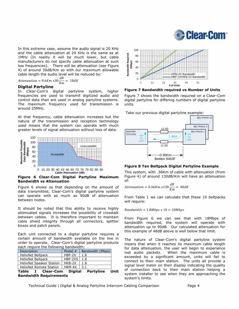
Figure 7 Bandwidth required vs Number of Units
Figure 7 shows the bandwidth required on a Clear-Com
digital partyline for differing numbers of digital partyline units. Take our previous digital partyline example:
BELTPACK 10
BELTPACK 2
MASTER
STATION
BELTPACK 1
12.3Ω
12.3Ω
1.46A60V
DC
OUT
24V
DC
MIN
0.36KmBelden 9463F
Figure 8 Ten Beltpack Digital Partyline Example
This system, with .36Km of cable with attenuation (from Figure 4) of around 130dB/Km will have an attenuation of:
𝐴𝑡𝑡𝑒𝑛𝑢𝑎𝑡𝑖𝑜𝑛 = 0.36𝐾𝑚 𝑥130𝑑𝐵
𝐾𝑚= 48𝑑𝐵
From Table 1 we can calculate that these 10 beltpacks will require: 𝐵𝑎𝑛𝑑𝑤𝑖𝑑𝑡ℎ = 1.8𝑀𝑏𝑝𝑠 𝑥 10 = 18𝑀𝑏𝑝𝑠
From Figure 6 we can see that with 18Mbps of bandwidth required, the system will operate with attenuation up to 90dB. Our calculated attenuation for this example of 48dB above is well below that limit.
The nature of Clear-Com’s digital partyline system
means that when it reaches its maximum cable length for data attenuation, the user will begin to experience lost audio packets. When the maximum cable is exceeded by a significant amount, units will fail to connect to their main station. The units all provide a signal level meter on their display indicating the quality
of connection back to their main station helping a system installer to see when they are approaching the system’s limits.
0
20
40
60
80
100
120
0 10 20 30 40 43 46 60 70 76 79 82 85 90
Maxim
um
Po
ssib
le
Data
Ban
dw
idth
(M
bp
s)
Cable Attenuation (dB)
Acceptable
Unacceptable
0
20
40
60
80
100
1 11 21 31 41 51
Ban
dw
idth
Req
uir
ed
(Mb
ps)
# of Units
HRM-4X BandwidthHBP-2X/HKB-2X Bandwidth

Technical Guide |
Digital & Analog Partyline Intercom Cabling Comparison Page 5
Conclusions Cable Types Analog and digital partyline intercom systems place different demands on the cables used and whilst some cables are very good for both systems, some that are
fine for one are not good for the other.
Analog systems require good shielding and little attention needs to be paid to attenuation at higher signal frequencies.
Digital systems require particular attention be
paid to attenuation at frequencies into the MHz
range.
Due to the combination of their low DC resistance and low attenuation at 25MHz data rates, Clear-Com recommends the use of:
Belden 9207 cable for fixed digital partyline
installations. Belden 9463F cable for portable or temporary
digital partyline installations.
See Belden’s website at: www.belden.com for
more details.
It is worthy of note that star quad cables have very high
attenuation at 25MHz making them particularly poorly suited to digital partyline applications.
Limit Conditions The nature of analog and digital systems dictates that their failure mechanisms are different when cable requirements aren’t met.
Figure 9 and Figure 10 below give a comparison of what a user can expect from analog and digital partyline systems when approaching the limits of their cable’s capabilities.
Calculator The information included in this technical guide can be
used to calculate the maximum acceptable cable length for any Clear-Com digital partyline system. Alternatively, a user or prospective user can use the calculator spreadsheet available at the link below to determine whether a particular cabling installation meets the requirements of Clear-Com digital partyline.
Digital Partyline Calculator
Cable Length
Nu
mb
er
of U
nits
Excellent
Performance
Good
Performance
Satisfactory
Performance
Degraded
Performance
Does Not
Operate
Figure 9 Analog Partyline Performance with increasing Cable Length and Number of Units
Cable Length
Nu
mb
er
of U
nits
Excellent
Performance
Degraded
Performance
Does Not
Operate
Figure 10 Digital Partyline Performance with Increasing Cable Length and Number of Units


