Page 1
ISO 9001:2015 Certified
Copyright Quasonix, Inc., All Rights Reserved.
Technical Guide
Low Density Parity Check (LDPC)
Quasonix, Inc.
6025 Schumacher Park Dr.
West Chester, OH 45069
24 September 2019
*** Revision 1.0 ***
Specifications subject to change without notice.
All Quasonix products are under U.S. Department of Commerce jurisdiction; not covered by ITAR
Page 2
Technical Guide: LDPC
i Quasonix, Inc.
Table of Contents
1 What is LDPC? ...................................................................................................................................... 1
1.1 LDPC Availability on Transmitters ............................................................................................... 1
1.2 LDPC Availability on Receivers and Receiver Analyzers ............................................................ 2
2 How Do I Decide Which LDPC Code to Use? ....................................................................................... 3
2.1 Coding Gain ................................................................................................................................. 3
2.2 Bandwidth .................................................................................................................................... 4
2.3 Synchronization Time .................................................................................................................. 4
2.4 Other Considerations ................................................................................................................... 4
2.4.1 Latency .................................................................................................................................... 4
2.4.2 Randomization......................................................................................................................... 5
2.4.3 Bit Rate .................................................................................................................................... 5
3 How Do I Use LDPC with a Quasonix TIMTER Transmitter? ................................................................ 6
4 How Do I Use LDPC with a Quasonix Dual Transmitter? ...................................................................... 8
4.1 Low Density Parity Check Commands for LD or LD6 ................................................................. 8
5 How Do I Use LDPC with a Quasonix Receiver? ................................................................................ 12
5.1 LDPC Commands for Compact Receivers (or Rack Mount Receivers Via Telnet) ................... 13
5.1.1 Forward Error Correction Command – FEC .......................................................................... 13
5.1.2 Low Density Parity Check Command – LDPC ...................................................................... 14
6 How Do I Use LDPC with a Quasonix Receiver Analyzer? ................................................................. 15
6.1 Bench Set Up for STC and LDPC ............................................................................................. 16
6.1.1 Receiver Connections ........................................................................................................... 16
6.1.1.1 Compact Receiver ............................................................................................................. 17
6.1.1.2 Rack Mount Receiver ........................................................................................................ 17
6.1.2 Transmitter Commands ......................................................................................................... 19
Page 3
Technical Guide: LDPC
ii Quasonix, Inc.
List of Figures
Figure 1: SOQPSK/LDPC Detection Performance Relative to PCMFM (ARTM Tier 0), SOQPSK (ARTM
Tier I), and Multi-h CPM (ARTM Tier II) ........................................................................................................ 3
Figure 2: Advanced Menu, LDPC Mode ..................................................................................................... 12
Figure 3: LDPC Mode Selections ................................................................................................................ 12
Figure 4: Advanced Settings Window, LDPC Mode Drop Down Menu ...................................................... 12
Figure 5: Receiver Analyzer Controls Screen, Modulator Section Open .................................................... 15
Figure 6: Receiver Analyzer Controls Screen, Modulator, LDPC Selection ............................................... 15
Figure 7: Quasonix Dual Transmitter .......................................................................................................... 16
Figure 8: Example STC Field Configuration for Dual Transmitter and Rack Mount Receiver .................... 16
Figure 9: Example Bench RF Configuration for Single Transmitter and Compact Receiver ...................... 17
Figure 10: Example Bench RF Configuration for Dual Transmitter and Compact Receiver ...................... 17
Figure 11: Example Bench RF Configuration for Single Transmitter and Rack Mount Receiver ............... 18
Figure 12: Example Bench RF Configuration for Dual Transmitter and Rack Mount Receiver—Without
STC ............................................................................................................................................................. 18
Figure 13: Example Bench RF Configuration for Dual Transmitter and Rack Mount Receiver—With STC
.................................................................................................................................................................... 18
Figure 14: Quasonix Dual Transmitter ........................................................................................................ 19
List of Tables
Table 1: LDPC Bandwidth Expansion ........................................................................................................... 4
Table 2: LDPC User Command .................................................................................................................... 7
Table 3: LDPC User Commands ................................................................................................................ 10
Table 4: Dual Transmitter Input Commands for Channel 1 and Channel 2 ................................................ 19
Page 4
Technical Guide: LDPC
1 Quasonix, Inc.
1 What is LDPC?
Low-Density Parity Check (LDPC) encoding is a form of forward error correction (FEC). It works by adding
redundant information at the transmitting end of a telemetry link and then using that redundancy to detect and
correct errors at the receiving end of the link. Details of LDPC coding are presented in IRIG 106-17 Appendix 2-D.
LDPC encoding can have many benefits. Its most common use is in range extension, where bit errors occur due to a
weak received signal. LDPC can improve the point at which errors start to occur by over 9 dB. This increase in link
margin is equivalent to almost tripling the operating distance of the telemetry link. Another application is error
suppression—for links like compressed video that suffer major degradation due to small numbers of errored bits.
LDPC has such a steep bit error rate curve that it converts the channel into essentially binary performance—
perfection or highly errored. Since perfection is achieved deep into the area where occasional bit errors would
normally occur, compressed video performance is greatly enhanced. Ultimately, any channel that can benefit from
error reduction and has bandwidth available will likely benefit from LDPC encoding.
The IRIG standard calls out six variants of LDPC codes—all combinations of two different information block sizes
(k=4096 bits and k=1024 bits) and three different code rates (r=1/2, r=2/3, and r=4/5).
k=4096, r=1/2
k=1024, r=1/2
k=4096, r=2/3
k=1024, r=2/3
k=4096, r=4/5
k=1024, r=4/5
The standard specifies LDPC coding only for SOQPSK modulations, including SOQPSK with Space Time Coding
(STC). When in SOQPSK/LDPC or STC/LDPC mode, the appropriate code (k, r) must be selected for proper
operation. Also, in these modes only, the user may select between no derandomization, standard IRIG
derandomization as specified in IRIG 106-17 Annex A-2, or CCSDS derandomization as specified in IRIG 106-17
Appendix 2-D. Again, the derandomization selection must match the encoding selected at the transmitting end for
proper operation.
SOQPSK/LDPC uses trellis demodulation. Trellis bit error rate performance in pure additive noise is slightly better
than single-symbol bit error rate performance, as shown in IRIG 106-17. Trellis synchronization under adverse
conditions may be significantly faster than single-symbol synchronization.
1.1 LDPC Availability on Transmitters
LDPC is available on some TIMTER transmitters, nanoPuck transmitters, and Dual transmitters when ordered as an
LD or LD6 option.
The LD option provides k=4096, r=2/3 Low Density Parity Check (LDPC) encoding, which is the specific variant,
for use on the integrated Network Enhanced Telemetry (iNET) program.
The LD6 option adds the extended LDPC option to the unit. It lets the user select from the six implemented LDPC
codes, and allows the randomizer command to select the CCSDS randomizer, if LDPC is enabled. Adding this
option automatically enables the existing LD option.
Page 5
Technical Guide: LDPC
2 Quasonix, Inc.
1.2 LDPC Availability on Receivers and Receiver Analyzers
LDPC functionality is built-in to all 3rd Generation Rack Mount RDMS Telemetry Receivers and Receiver
Analyzers.
Page 6
Technical Guide: LDPC
3 Quasonix, Inc.
2 How Do I Decide Which LDPC Code to Use?
Selecting the “best” LDPC code among the six available codes requires evaluating a number of tradeoffs. The
following information is intended to highlight the primary considerations involved in this evaluation. However, each
telemetry system has unique needs and characteristics, so the optimal code choice for any application may require
empirical testing to determine.
Tradeoffs primarily involve:
• Coding gain
• Bandwidth
• Synchronization time
2.1 Coding Gain
All LDPC codes specified in IRIG 106-17 provide excellent reduction in bit error rate (BER) near sensitivity. For
SOQPSK, this improvement in link margin ranges from roughly 7.3 to 9.5 dB, depending on the selected block size
and code rate:
Figure 1: SOQPSK/LDPC Detection Performance Relative to PCMFM (ARTM Tier 0), SOQPSK (ARTM Tier I), and Multi-h CPM (ARTM Tier II)
Note the steepness of the BER curves for LDPC. This characteristic may dramatically improve performance in
applications such as compressed video, in which even a small number of errors may make the link unusable.
Clearly, lower code rate improves coding gain, and larger block size improves coding gain. While the differences
between codes are not huge, they may be noticeable in some applications.
Page 7
Technical Guide: LDPC
4 Quasonix, Inc.
2.2 Bandwidth
The redundant information encoded into LDPC code blocks increases the encoded bit rate relative to the user bit
rate. As shown in Table 1, the amount of bandwidth expansion is dependent solely on the code rate r:
Table 1: LDPC Bandwidth Expansion
Information Block Length k
Bandwidth Expansion Factor
Rate r = 1/2 Rate r = 2/3 Rate r = 4/5
1024 33/16 25/16 21/16
4096 33/16 25/16 21/16
For example, if the user bit rate is 6.2 Mb/s and the selected code is k=4095, r=2/3, then the bandwidth expansion is
25/16, and the encoded over-the-air bit rate is (25/16)*(6.2 Mb/s) = 9.6875 Mb/s.
If occupied bandwidth is a concern, the user may select a higher code rate to keep the bandwidth expansion to a
minimum, at the expense of coding gain. Conversely, if occupied bandwidth is not a concern, the user may select a
lower code rate to increase coding gain, at the expense of increased bandwidth. Generally, the lowest code rate that
fits within the allowable bandwidth will provide the best performance.
2.3 Synchronization Time
LDPC block synchronization requires detecting attached sync markers (ASMs) prepended to each LDPC code
block. Therefore, synchronization time includes, on average, one half of an LDPC block to find the next transmitted
ASM. This means that shorter blocks will synchronize more quickly than longer blocks.
In applications where dropouts are frequent (e.g., link margin is limited predominantly by multipath), the user may
select a shorter block size to keep the synchronization time to a minimum, at the expense of coding gain.
Conversely, if dropouts are not a concern (e.g., link margin is limited predominantly by distance), the user may
select a longer block size to increase coding gain, at the expense of increased synchronization time.
Related, LPDC block decoding ultimately results in a successfully decoded block with no errors, or a failed block
with a very high number of errors—generally exceeding 10% BER for the entire block. Short bursts of link
degradation (e.g., due to a pulsed radar interferer) may corrupt an entire code block with little other effect. In this
case, less data will be lost if the block length is shorter.
2.4 Other Considerations
2.4.1 Latency
Some systems require minimal latency through the telemetry link. For a Quasonix transmitter/receiver pair, LDPC
increases system latency—from transmitter input to receiver output—by approximately
where k and r are the block size and code rate and N is the ASM length (in bits). This increase tends to dominate
overall system latency. Since this scales roughly proportional to block length, latency can be reduced substantially
by selecting a shorter block length.
2𝑘 + 1 − 𝑟 𝑘2
𝑟𝑁 + 𝑘
Page 8
Technical Guide: LDPC
5 Quasonix, Inc.
2.4.2 Randomization
IRIG 106-17 specifies two different randomizers for telemetry data: the RNRZ-L randomizer (also referred to as
IRIG randomization) and the CCSDS randomizer.
The IRIG randomizer is self-synchronizing, which results in a 3x error multiplication in the derandomizer. That is,
for each isolated bit error presented to the derandomizer, three bit errors will be output from the derandomizer. The
CCSDS randomizer uses the LDPC ASM for synchronization, so it is only available when LDPC is enabled, but it
has no error multiplication. For this reason, the IRIG standard recommends using CCSDS randomization when
LDPC is enabled. However, in many applications, CCSDS randomization may result in degraded system
performance.
CCSDS derandomization occurs within the LDPC decoder in the receiver. This means that, downstream from the
LDPC decoder, data will no longer be random. This may adversely affect performance of downstream equipment
such as bit syncs that rely on transitions in the data to maintain synchronization. It will also negatively impact
correlation in source selectors, including the RDMS™ Best Channel Selector (BCS). This degradation may cause
much worse data dropouts than the loss due to error multiplication (which, as shown in Figure 1, would result in less
than 0.1 dB effective reduction in link margin, due to the steepness of the LDPC BER curves).
Further, the CCSDS randomizer uses a very short (255-bit) randomization pattern. As noted in the CCSDS standard,
this may introduce spectral lines at 1/255 of the symbol rate. These may be significant in some systems, resulting in
acquisition or other issues.
IRIG 106 guidance notwithstanding, Quasonix recommends using IRIG randomization for all non-random data, with
or without LDPC. If ground station equipment has no sensitivity to data randomness, derandomization may be
performed in the receiver. If ground station equipment is sensitive to data randomness, derandomization may be
deferred to the decom.
2.4.3 Bit Rate
LDPC decoding is performed iteratively. The greater the number of iterations, the more likely a corrupted LDPC
code block can be successfully decoded. While the decoder is optimized to use all available time, the available time
is finite, limited by the duration of each code block.
At higher bit rates, the LDPC decoder has less time per code block for iterative decoding. Accordingly, coding gain
is reduced at high bit rates from the curves shown in Figure 1. This effect is minimal for r= 2/3 and r=4/5 codes, but
the r=1/2 code is noticeably impacted. Regardless, its performance at any bit rate is never worse than the other code
rates.
Page 9
Technical Guide: LDPC
6 Quasonix, Inc.
3 How Do I Use LDPC with a Quasonix TIMTER Transmitter?
When ordering a Quasonix TIMTER transmitter or a nanoPuck transmitter, request the LD or LD6 option.
For setup and configuration via a standard Windows-based PC, you may use HyperTerminal. For a more flexible,
full-featured control interface, we recommend Terminal, available for download from the Quasonix website
(Documents tab > Accessories link) or directly at:
http://www.quasonix.com/sites/default/files/terminal_ver20080315.zip.
The LDPC user command in Table 2 consists of two alphabetic characters, followed by 0, 1, or 2 arguments. If the
command is issued with arguments, there must be a space after the alphabetic characters. The commands are not
case sensitive. A carriage return is required to initiate each command. Detailed information about serial command
operation may be found in the TIMTER™ Multi-Mode Digital Telemetry Transmitter Installation and Operation
Manual or the nanoTX™ Telemetry Transmitter Installation and Operation Manual.
The LD command enables, disables, and shows the current state of the Forward Error Correction (FEC) / Low
Density Parity Check (LDPC) encoder. There is an optional selection for the block and rate selection. This requires
purchase of the LD6 option which enables LD and enables user code selection. LD6 also allows the randomizer
command to select CCSDS, if LDPC is enabled.
Enabling LDPC is only valid in *PSK modes and STC mode. In the *PSK modes, it automatically turns OFF
differential encoding. When LDPC is disabled, the state of DE is determined by the mode (for example, all *PSK
modes default to DE On, while STC mode defaults to DE Off.)
If the transmitter includes the LD option, then LD 0 or LD 1 are used to disable or enable LDPC, as shown in the
example immediately following. With the LD option, the block size and code rate are always 4096 2/3.
Examples:
LD Show the current encoder state
LD 1 Enable the LDPC encoder
LD 0 Disable the LDPC encoder
If the transmitter includes the LD6 option, the user may select from the six implemented LDPC codes. This also
allows user selection of the CCSDS randomizer. Adding LD6 automatically enables the existing LD option.
The IRIG standard calls out six variants of LDPC codes—all combinations of two different information block sizes
(k=4096 bits and k=1024 bits) and three different code rates (r=1/2, r=2/3, and r=4/5).
LD6 Code Block Size and Code Rate
0 k=4096, r=1/2
1 k=1024, r=1/2
2 k=4096, r=2/3
3 k=1024, r=2/3
4 k=4096, r=4/5
5 k=1024, r=4/5
Page 10
Technical Guide: LDPC
7 Quasonix, Inc.
With the LD6 option, use LD 0 or 1 to disable or enable LDPC, then use 0-5 to indicate the desired LDPC code. A
space is required between the disable/enable code and the desired LDPC selection, as shown in the examples.
Examples:
LD 0 Disable the LDPC encoder
LD 1 2 Enable the LDPC encoder and set the block size and code rate to k=4096, r=2/3
LD 1 5 Enable the LDPC encoder and set the block size and code rate to k=1024, r=4/5
Table 2: LDPC User Command
Mnemonic Command
Name Description Option (s) Required
Setting Saved?
Factory Default
LD LDPC Encoding Enable
Enable, disable, or show the current state of the Forward Error Correction (FEC) / Low Density Parity Check (LDPC) encoder
Valid options are 0 and 1
Examples:
LD Show the current encoder state
LD 1 Enable the LDPC encoder
LD 0 Disable the LDPC encoder
Automatically disables differential encoding; *PSK modes default to DE enabled
Automatically re-enables DE for SOQPSK mode
Refer to section 4.1 for additional LD command detail
LD, LD6
*PSK modes
Y LD 0
Page 11
Technical Guide: LDPC
8 Quasonix, Inc.
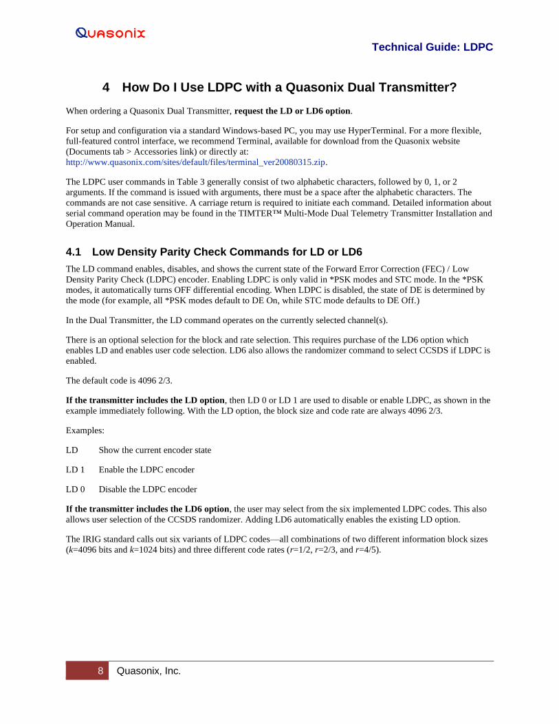
4 How Do I Use LDPC with a Quasonix Dual Transmitter?
When ordering a Quasonix Dual Transmitter, request the LD or LD6 option.
For setup and configuration via a standard Windows-based PC, you may use HyperTerminal. For a more flexible,
full-featured control interface, we recommend Terminal, available for download from the Quasonix website
(Documents tab > Accessories link) or directly at:
http://www.quasonix.com/sites/default/files/terminal_ver20080315.zip.
The LDPC user commands in Table 3 generally consist of two alphabetic characters, followed by 0, 1, or 2
arguments. If the command is issued with arguments, there must be a space after the alphabetic characters. The
commands are not case sensitive. A carriage return is required to initiate each command. Detailed information about
serial command operation may be found in the TIMTER™ Multi-Mode Dual Telemetry Transmitter Installation and
Operation Manual.
4.1 Low Density Parity Check Commands for LD or LD6
The LD command enables, disables, and shows the current state of the Forward Error Correction (FEC) / Low
Density Parity Check (LDPC) encoder. Enabling LDPC is only valid in *PSK modes and STC mode. In the *PSK
modes, it automatically turns OFF differential encoding. When LDPC is disabled, the state of DE is determined by
the mode (for example, all *PSK modes default to DE On, while STC mode defaults to DE Off.)
In the Dual Transmitter, the LD command operates on the currently selected channel(s).
There is an optional selection for the block and rate selection. This requires purchase of the LD6 option which
enables LD and enables user code selection. LD6 also allows the randomizer command to select CCSDS if LDPC is
enabled.
The default code is 4096 2/3.
If the transmitter includes the LD option, then LD 0 or LD 1 are used to disable or enable LDPC, as shown in the
example immediately following. With the LD option, the block size and code rate are always 4096 2/3.
Examples:
LD Show the current encoder state
LD 1 Enable the LDPC encoder
LD 0 Disable the LDPC encoder
If the transmitter includes the LD6 option, the user may select from the six implemented LDPC codes. This also
allows user selection of the CCSDS randomizer. Adding LD6 automatically enables the existing LD option.
The IRIG standard calls out six variants of LDPC codes—all combinations of two different information block sizes
(k=4096 bits and k=1024 bits) and three different code rates (r=1/2, r=2/3, and r=4/5).
Page 12
Technical Guide: LDPC
9 Quasonix, Inc.
LD6 Code Block Size and Code Rate
0 k=4096, r=1/2
1 k=1024, r=1/2
2 k=4096, r=2/3
3 k=1024, r=2/3
4 k=4096, r=4/5
5 k=1024, r=4/5
With the LD6 option, use LD 0 or 1 to disable or enable LDPC, then use 0-5 to indicate the desired LDPC code. A
space is required between the disable/enable code and the desired LDPC selection, as shown in the examples.
Examples:
LD 0 Disable the LDPC encoder
LD 1 2 Enable the LDPC encoder and set the block size and code rate to k=4096, r=2/3
LD 1 5 Enable the LDPC encoder and set the block size and code rate to k=1024, r=4/5
Page 13
Technical Guide: LDPC
10 Quasonix, Inc.
Table 3: LDPC User Commands
Mnemonic Command
Name Description Option (s) Required
Setting Saved?
Factory Default
LD LDPC Encoding Enable
Enable, disable, or show the current state of the Forward Error Correction (FEC) / Low Density Parity Check (LDPC) encoder
Valid options are 0 and 1
Examples:
LD Show the current encoder state
LD 1 Enable the LDPC encoder
LD 0 Disable the LDPC encoder
Automatically disables differential encoding; *PSK modes default to DE enabled
Automatically re-enables DE for SOQPSK mode
Refer to section 4.1 for additional LD command detail
LD, LD6
*PSK modes
Y LD 0
LHS LDPC Header Selects the header to use with Low Density Parity Check coding on the unit
Valid options are 0 and 1
Examples:
LHS Show the current header
LHS 0 Set header to SOQPSK/LDPC
LHS 1 iNet test header
LD Y LHS 0
Page 14
Technical Guide: LDPC
11 Quasonix, Inc.
Mnemonic Command
Name Description Option (s) Required
Setting Saved?
Factory Default
LPE LDPC Parity Enable
Enables the parity calculation with Low Density Parity Check coding
Valid options are 0 and 1
Examples:
LPE Show the current LPE state
LPE 1 Enable the parity calculation
LPE 0 Disable the parity calculation
LD Y LPE 1
Page 15
Technical Guide: LDPC
12 Quasonix, Inc.
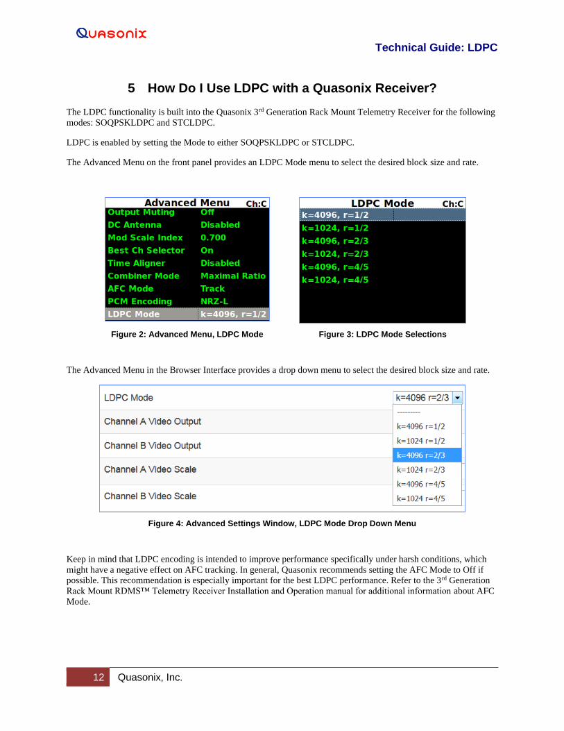
5 How Do I Use LDPC with a Quasonix Receiver?
The LDPC functionality is built into the Quasonix 3rd Generation Rack Mount Telemetry Receiver for the following
modes: SOQPSKLDPC and STCLDPC.
LDPC is enabled by setting the Mode to either SOQPSKLDPC or STCLDPC.
The Advanced Menu on the front panel provides an LDPC Mode menu to select the desired block size and rate.
Figure 2: Advanced Menu, LDPC Mode Figure 3: LDPC Mode Selections
The Advanced Menu in the Browser Interface provides a drop down menu to select the desired block size and rate.
Figure 4: Advanced Settings Window, LDPC Mode Drop Down Menu
Keep in mind that LDPC encoding is intended to improve performance specifically under harsh conditions, which
might have a negative effect on AFC tracking. In general, Quasonix recommends setting the AFC Mode to Off if
possible. This recommendation is especially important for the best LDPC performance. Refer to the 3rd Generation
Rack Mount RDMS™ Telemetry Receiver Installation and Operation manual for additional information about AFC
Mode.
Page 16
Technical Guide: LDPC
13 Quasonix, Inc.
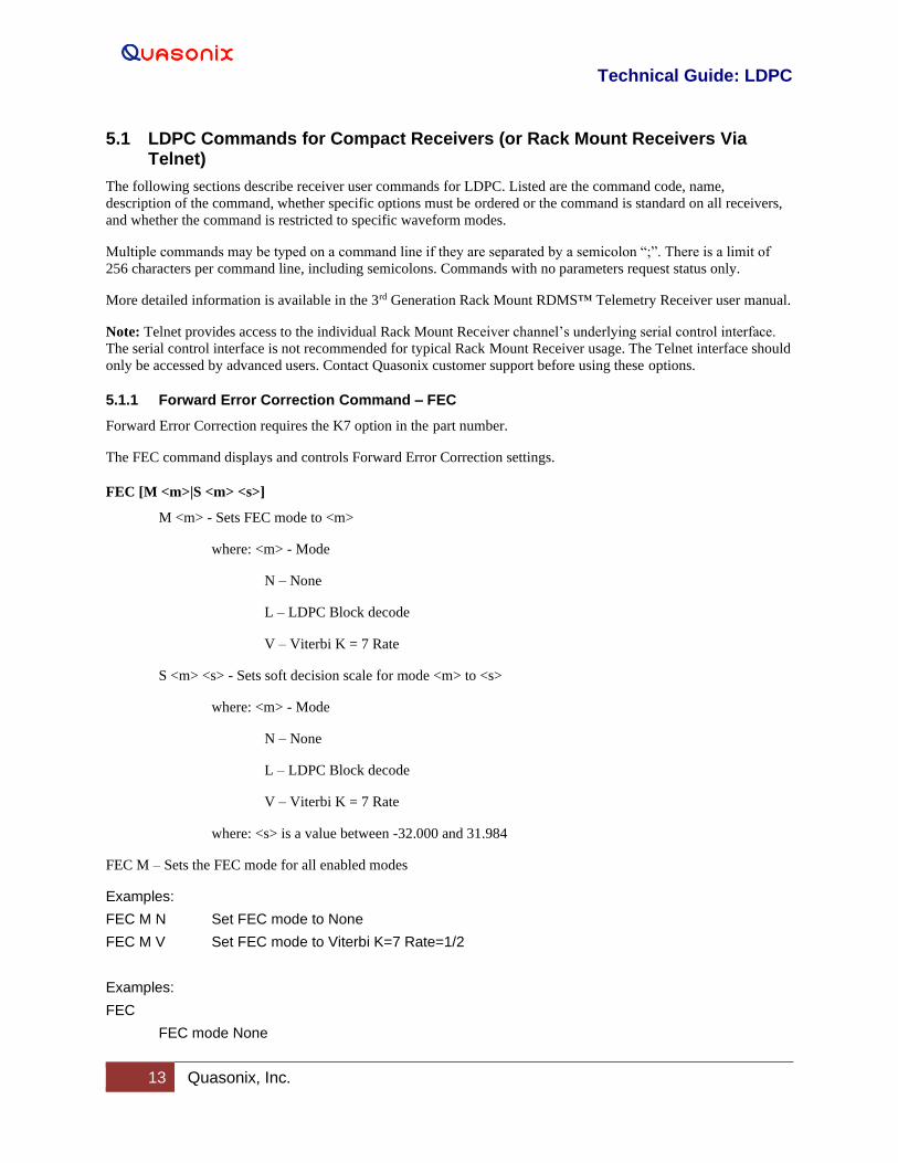
5.1 LDPC Commands for Compact Receivers (or Rack Mount Receivers Via Telnet)
The following sections describe receiver user commands for LDPC. Listed are the command code, name,
description of the command, whether specific options must be ordered or the command is standard on all receivers,
and whether the command is restricted to specific waveform modes.
Multiple commands may be typed on a command line if they are separated by a semicolon “;”. There is a limit of
256 characters per command line, including semicolons. Commands with no parameters request status only.
More detailed information is available in the 3rd Generation Rack Mount RDMS™ Telemetry Receiver user manual.
Note: Telnet provides access to the individual Rack Mount Receiver channel’s underlying serial control interface.
The serial control interface is not recommended for typical Rack Mount Receiver usage. The Telnet interface should
only be accessed by advanced users. Contact Quasonix customer support before using these options.
5.1.1 Forward Error Correction Command – FEC
Forward Error Correction requires the K7 option in the part number.
The FEC command displays and controls Forward Error Correction settings.
FEC [M <m>|S <m> <s>]
M <m> - Sets FEC mode to <m>
where: <m> - Mode
N – None
L – LDPC Block decode
V – Viterbi K = 7 Rate
S <m> <s> - Sets soft decision scale for mode <m> to <s>
where: <m> - Mode
N – None
L – LDPC Block decode
V – Viterbi K = 7 Rate
where: <s> is a value between -32.000 and 31.984
FEC M – Sets the FEC mode for all enabled modes
Examples:
FEC M N Set FEC mode to None
FEC M V Set FEC mode to Viterbi K=7 Rate=1/2
Examples:
FEC
FEC mode None
Page 17
Technical Guide: LDPC
14 Quasonix, Inc.
5.1.2 Low Density Parity Check Command – LDPC
The LDPC command displays and controls Forward Error Correction settings.
LDPC [M <m>|A <t>|I <s>]
M <m> - Sets LDPC mode to <m>. LDPC mode is stored and transferred if the (waveform) Mode changes.
where: <m> - LDPC Mode
4k1 – 4k Rate 1/2
1k1 – 1k Rate 1/2
4k2 – 4k Rate 2/3
1k2 – 1k Rate 2/3
4k4 – 4k Rate 4/5
1k4 – 1k Rate 4/5
A <t> - Sets ASM threshold to <t>, 0 to 65535. This is not a stored parameter.
I <s> - Sets half iteration scale to <s>, 0.100 to 1.000
Examples:
LDPC
LDPC mode 4k Rate 2/3
LDPC decode ASM threshold 192
LDPC decode half iteration scale 0.900
LDPC A 42 LDPC decode ASM threshold 42
LDPC I .567 LDPC decode half iteration scale 0.567
Page 18
Technical Guide: LDPC
15 Quasonix, Inc.
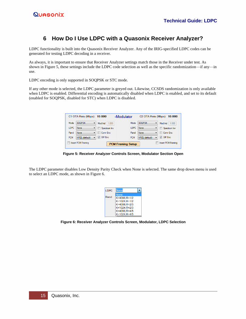
6 How Do I Use LDPC with a Quasonix Receiver Analyzer?
LDPC functionality is built into the Quasonix Receiver Analyzer. Any of the IRIG-specified LDPC codes can be
generated for testing LDPC decoding in a receiver.
As always, it is important to ensure that Receiver Analyzer settings match those in the Receiver under test. As
shown in Figure 5, these settings include the LDPC code selection as well as the specific randomization—if any—in
use.
LDPC encoding is only supported in SOQPSK or STC mode.
If any other mode is selected, the LDPC parameter is greyed out. Likewise, CCSDS randomization is only available
when LDPC is enabled. Differential encoding is automatically disabled when LDPC is enabled, and set to its default
(enabled for SOQPSK, disabled for STC) when LDPC is disabled.
Figure 5: Receiver Analyzer Controls Screen, Modulator Section Open
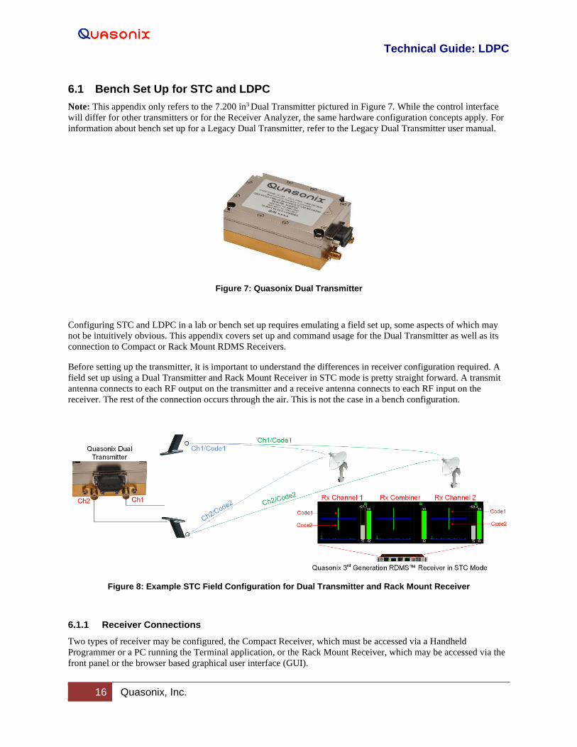
The LDPC parameter disables Low Density Parity Check when None is selected. The same drop down menu is used
to select an LDPC mode, as shown in Figure 6.
Figure 6: Receiver Analyzer Controls Screen, Modulator, LDPC Selection
Page 19
Technical Guide: LDPC
16 Quasonix, Inc.
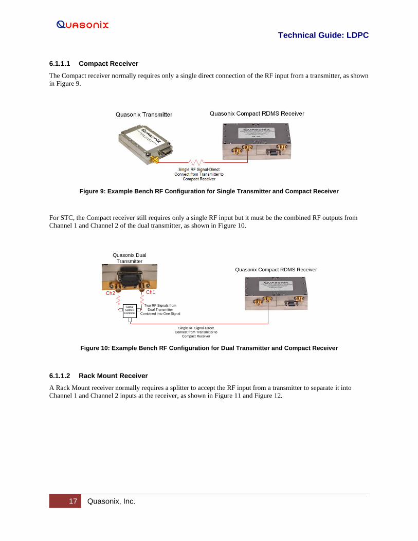
6.1 Bench Set Up for STC and LDPC
Note: This appendix only refers to the 7.200 in3 Dual Transmitter pictured in Figure 7. While the control interface
will differ for other transmitters or for the Receiver Analyzer, the same hardware configuration concepts apply. For
information about bench set up for a Legacy Dual Transmitter, refer to the Legacy Dual Transmitter user manual.
Figure 7: Quasonix Dual Transmitter
Configuring STC and LDPC in a lab or bench set up requires emulating a field set up, some aspects of which may
not be intuitively obvious. This appendix covers set up and command usage for the Dual Transmitter as well as its
connection to Compact or Rack Mount RDMS Receivers.
Before setting up the transmitter, it is important to understand the differences in receiver configuration required. A
field set up using a Dual Transmitter and Rack Mount Receiver in STC mode is pretty straight forward. A transmit
antenna connects to each RF output on the transmitter and a receive antenna connects to each RF input on the
receiver. The rest of the connection occurs through the air. This is not the case in a bench configuration.
Figure 8: Example STC Field Configuration for Dual Transmitter and Rack Mount Receiver
6.1.1 Receiver Connections
Two types of receiver may be configured, the Compact Receiver, which must be accessed via a Handheld
Programmer or a PC running the Terminal application, or the Rack Mount Receiver, which may be accessed via the
front panel or the browser based graphical user interface (GUI).
Page 20
Technical Guide: LDPC
17 Quasonix, Inc.
6.1.1.1 Compact Receiver
The Compact receiver normally requires only a single direct connection of the RF input from a transmitter, as shown
in Figure 9.
Figure 9: Example Bench RF Configuration for Single Transmitter and Compact Receiver
For STC, the Compact receiver still requires only a single RF input but it must be the combined RF outputs from
Channel 1 and Channel 2 of the dual transmitter, as shown in Figure 10.
Figure 10: Example Bench RF Configuration for Dual Transmitter and Compact Receiver
6.1.1.2 Rack Mount Receiver
A Rack Mount receiver normally requires a splitter to accept the RF input from a transmitter to separate it into
Channel 1 and Channel 2 inputs at the receiver, as shown in Figure 11 and Figure 12.
Quasonix Dual
Transmitter
Ch2 Ch1
Two RF Signals from
Dual Transmitter
Combined into One Signal
Signal
Splitter/
Combiner
Single RF Signal-Direct
Connect from Transmitter to
Compact Receiver
Quasonix Compact RDMS Receiver
Page 21
Technical Guide: LDPC
18 Quasonix, Inc.
Figure 11: Example Bench RF Configuration for Single Transmitter and Rack Mount Receiver
Figure 12: Example Bench RF Configuration for Dual Transmitter and Rack Mount Receiver—Without STC
For STC, the Rack Mount receiver still requires a splitter to accept the RF input, but the input to the splitter must be
combined RF outputs from Channel 1 and Channel 2 of a dual transmitter, as shown in Figure 13.
Figure 13: Example Bench RF Configuration for Dual Transmitter and Rack Mount Receiver—With STC
Single RF Signal from Transmitter Sent to Splitter
Quasonix Rack Mount RDMS Receiver
Quasonix
Transmitter
RF Signal Split into
CH1 and CH2
Sig
na
l
Sp
litter/
Co
mb
ine
r
Single RF Signal Sent to Splitter
RF Signal Split into
CH1 and CH2
Quasonix Rack Mount RDMS Receiver
Without STC,
RF Signal-Direct Connect from Transmitter
Channel 1 to Splitter
Quasonix Dual
Transmitter
Ch1
Sig
na
l
Sp
litter/
Co
mb
ine
r
Single RF Signal Sent to Splitter
Quasonix Dual
Transmitter
Ch2 Ch1
Two RF Signals from
Dual Transmitter
Combined into One Signal
Signal
Splitter/
Combiner
Sig
na
l
Sp
litter/
Co
mb
ine
r
RF Signal Split into
CH1 and CH2
Quasonix Rack Mount RDMS Receiver
Page 22
Technical Guide: LDPC
19 Quasonix, Inc.
6.1.2 Transmitter Commands
The Dual transmitter, shown in Figure 14, enables several configurations including SOQPSK only, SOQPSK with
LDPC, SOQPSK with STC, and SOQPSK with LDPC and STC. In addition to establishing the correct connection(s)
to a receiver, proper configuration requires setting up the transmitter with a small number of commands.
Figure 14: Quasonix Dual Transmitter
When running STC on a Dual Transmitter, both channels must be set up identically.
To facilitate this, type the CH 3 command prior to the other commands to automatically set both channels to the
same parameters. The channels may be set up one at a time but CH 3 prevents duplication of work.
Table 4 shows the commands required to set up the four possible configurations.
Table 4: Dual Transmitter Input Commands for Channel 1 and Channel 2
SOQPSK only
SOQPSK
+
LDPC
SOQPSK
+
STC
SOQPSK +
STC
+
LDPC
CH 3 CH 3 CH 3 CH 3
MO 1 MO 1 MO 13* MO 13*
LD 0 LD 1 LD 0 LD 1
*MO 13 sets the mode to STC.
When running SOQPSK or SOQPSK with LDPC, the frequency may be changed separately for Channel 1 and
Channel 2 by using the FR command on the appropriate channel. For STC, the Channel 1 and Channel 2 frequencies
should be set the same.


![Design LDPC Cyclepeng/itw07.pdfoptimized binary LDPC code in [5] by 0.38 dB. Due to its highly irregular degree sequence, the encoding complexity of the optimized binary LDPC code](https://static.documents.pub/doc/80x56/5e6fbb682ffa9d6ab8128325/design-ldpc-cycle-pengitw07pdf-optimized-binary-ldpc-code-in-5-by-038-db-due.jpg)


