20
EXTERNAL FIXATION SYSTEM TECHNICAL GUIDE

EXTERNAL FIXATION SYSTEM
TECHNICAL GUIDE

1. Ring
2. Ring Clamp
3. Wire Post
4. Pin Post
5. Ring to Monotube® Triax™ Tube Clamp, Ø20mm (Blue)Ring to Monotube® Triax™ Tube Clamp, Ø25mm (Red)
6. Kirschner-Wires and Apex® Half-Pins
7. (a) Hoffmann® II and (b) Triax™ Componentsfor Diaphyseal Fixation with Apex® Pins
8. Instruments
8 7b
7a
3
4
2
1
6
5

The Tenxor™ External Fixator is a hybrid
system providing advanced technology
and ease of application, designed to fulfil
the needs of today’s surgeon, by ensuring
ease of use, versatility and patient comfort.
What is a Hybrid Frame?A hybrid frame is a combination ofKirschner-wires and half-pins in a frameconstruct. It combines the principles ofcircular ring and modular or unilateralframe fixation to better neutralise theforces acting upon the fracture site.
Hybrid external fixation has become moreand more popular in the treatment of peri-articular fractures of the tibia. This type offrame configuration may be used tostabilise metaphyseal fractures, especiallyin osteoporotic bone (poor quality bonestock) or severely comminuted injurieswhere regular half-pins may loosenbecause of repetitive loading.
IndicationsSevere multifragmentary tibial plateauand pilon fractures with severe softtissue injury
Distal femoral fracture with soft tissuedamage
Peri-articular fractures where neitherinternal fixation nor regular half-pinscan be used
Overview
3
This publication sets forth detailed recommended procedures for usingStryker Howmedica Osteonics devices and instruments. It offersguidance that you should heed, but, as with any such technical guide,each surgeon must consider the particular needs of each patient andmake appropriate adjustments when and as required.

Anatomical Considerations for K-wire Insertion.Proximal Tibia
4
��������������������
����
17
11
10
9
15
18
20
14
12
6
1
2
5
7
8
34
19
16
1313
When inserting K-wires (Fig 2) it isimportant to ensure that the path theytake will avoid tendons and neurovascularbundles.
The head of the fibula is an importantlandmark, but as the peroneal nervepasses posterior to it care should betaken to avoid transfixation of the nervebundle.
The K-wires should be placed at least14mm below the joint line to avoid capsularpenetration. It may be desirable to pass aK-wire through the head of the fibula or justanteriorly. Greater care should be takenwith wires placed near the neck of the fibulaas this is where the branching of theperoneal nerve takes place.
Transfixation of the patellar tendon by theanterolateral to posteromedial wire mustbe avoided as this will cause pain andrestricted motion. The cross wire isinserted just anterior to the anterior-lateralcompartment muscles, it should notviolate the joint space, or thegastrocnemius muscle. Care should betaken not to place this too anteriorly asthis can cause damage to the hamstringattachment. Transfixation of the muscleleads to discomfort and restricted mobility.Should it be necessary to transfix themuscle, the muscle should be stretchedprior to insertion of the wire.
Figure 1
Figure 2
����
1. Tibia2. Tibial tuberosity3. Fibula4. Proximal tibio-fibular joint5. Patellar tendon6. Tibial collateral ligament of the knee7. Tibialis anterior8. Extensor digitorum longus9. Gracilis10. Sartorius11. Semitendinosus12. Popliteus13. Soleus14. Gastrocnemius (lateral head)15. Gastrocnemius (medial head)16. Popliteal vessels17. Long saphenous vein18. Short saphenous vein19. Common peroneal nerve20. Tibial nerve

The metaphyseal area indicated consistsof thin walled cortical bone not suitable forhalf-pin fixation (Fig 3). Apex® half pinsare designed for fixation into dense strongsubchondral bone. In this area tensionedK-wires are easy to apply, allowing formaximum wire crossing angles and stableconstructs.
Multiplanar K-wires create a constructcapable of buttressing againstvarus/valgus and flexion/extensiondeforming forces.
In the diaphysis the use of Apex® half pinsis known to give good long-term fixationwith low rates of loosening and pin tractinfection.
The Tenxor™ Hybrid Fixator providesoptimal fracture fixation by combining
tensioned K-wire fixation in themetaphysis with pin fixation in thediaphysis.
In cases of fractures of the tibia with intra-articular involvement, minor displacementor short oblique fractures of thediaphyseo-metaphyseal junction, theframe can be applied with two to fourwires proximally and two or three Apex®
pins in the mid-shaft. Additional pins canbe placed independently on the ring forgreater stability, particularly to enhanceresistance to flexion/extension instability,(Fig 4).
In more complex fractures using K-wireswith olives will allow for the fixation offracture fragments.
Proximal Tibial Fractures
5
Figure 3 Figure 4
WIRE INSERTION AREA
LIMIT OF CORTICALSCREW FIXATION

Pre-operative planning is used to assessthe orientation of the fracture lines and theextent of the articular surface depression.Important landmarks are marked on theskin. CT scans can be helpful.
Temporary reduction if appropriate iscarried out. Major fracture fragments aresecured using Stryker® Asnis™ IIIcannulated screws. Bone grafting, ifrequired, can be performed at this time.
The appropriate sized ring is chosenallowing for an even clearance ofapproximatly 2 finger widths around thelimb (Fig 5).
The ring is placed with the open area tothe back to allow for knee flexion.
Operative procedureWith all external fixation devices it isimportant to ensure that the path the wiresand pins take, avoids risk of injury tomajor blood vessels, tendons andneurovascular elements.
In areas of important neurovascularelements, the surgeon may choose toinsert the K-wires under direct vision.Make a 4cm incision dissecting thetissues down to the bone before insertingthe wire. In other areas a 1-2cm incisionis made. Please see Page 4 for a moredetailed description on wire placementand tissue identification.
The order in which K-wires are placed isleft to the surgeon’s discretion (Fig 6).Generally three K-wires are placed in theproximal tibia.
K-Wire insertion
Proximal Tibial Fractures
6
Figure 5 Figure 6

7
Using the split wire sleeve guide to holdthe K-wire and referencing the head of thefibula the first K-wire is placed parallel tothe joint surface and just anterior to, orthrough the fibular head. The commonperoneal nerve should be avoided duringwire insertion. The first K-wire exits thetibia anteromedially avoiding the patellartendon. Plain K-wires or K-wires with olivecan be used with the split wire sleeve guide(Fig 7).
At this point the ring can be connected tothe K-wire by using a pair of ring clampsand wire posts. The wire post is pushedinto the ring clamp, the two smallceramic stops on the post must line upwith the alignment mark on the ringclamp before insertion (Fig 8&9). Turnthe post by one quarter turn left or right toorientate the wire holder direction in thefield of the ring.The assemblies (one pair ofring clamps and wire posts) can now be‘clicked’ onto the ring on the inner or outerring surface. Placing the assemblies on theouter ring surface allow a greater wiremobility and easier access for tensioning.
Figure 7
Figure 8 Figure 9
SMALL STOPS
ALIGNMENT MARK

The ring can now be presented to the wireand the wire ‘clicked’ into the wire posts(Fig 10,10a).
If the wire needs adjusting it can beremoved from the post by pushing the innerclamping plate towards the 7mm screw and‘un-clicking’ the wire (Fig 10b).
The second K-wire is placed anterolateralto posteromedial and 40 to 60 degreesfrom the first K-wire. Again the wire isplaced parallel to the joint surface; itshould not violate the joint space, or thegastrocnemius muscle.
A second pair of ring clamps and wireposts are ‘clicked’ onto the ring and wire.
The third K-wire is placed medial-lateralbetween the first two wires. The position of
the K-wires can be checked on an imageintensifier and all three wires should forma small triangle at the centre (Fig 11).
The final pair of wire posts and ringclamps are ‘clicked’ into place.
The ring clamp/wire post assembly can beadjusted along the length of the ring. Eachwire post can be adjusted vertically up toa maximum of 25mm (Fig 12). This helpsto eliminate any bowing of the wires. Oncethis stage is completed the ring clamps canbe locked into place using the 13mmwrench to tighten the 13mm nut (Fig 13).
Alternatively all three K-wires can be placedprior to attachment to the ring.Convergence/divergence of K-wires can becompensated for by adjusting the height ofthe wire post proximally or distally.8
Figure 11 Figure 12
25MM
10a 10bFigure 10

Wire tensioning should now be performeduntil all the K-wires are in a satisfactoryposition.
The ring clamp must be locked onto thering. Once the ring clamps have beenlocked, any adjustment of the wire postis impossible.
Make sure that the wire post is parallel tothe K-wire. Any twisting can create astress riser, particularly during tensioning(Fig 15 inset).
Wire TensioningBefore tensioning the wire, it must belocked in place into one of the wireposts using the stabilization wrenchand the 7mm wrench (Fig 14). Thetension will then be performed on thewire section which remains unlocked.
When using K-wire with olive, the sidewith olive must be locked first, withsmooth K-wires either end can be locked.
The tensioning instrument requires aminimum of 70mm of wire (Fig 15).
Proximal Tibial Fractures
9
Figure 13 Figure 14
Figure 15
70mm Minimum
Stabilization Wrench

Fully open the wire tensioner and feed thewire through the centre of the instrumentuntil the instrument makes contact withthe wire post. Turn the T-handle clockwiseuntil the desired mark is reached: (Fig 16)
- first mark (50kg tension) for1.5mm wires
- second mark (100kg tension) for2.0mm wires
The wire is now fully tensioned.
Before removing the tensioner, use thestabilisation wrench & T-wrench to tighten the7mm screw to lock the wire in place.
Do not use the tensioner to applycounter force. This is then repeated onthe other K-wires.
For the Tenxor™ system, the bestprocedure to obtain the optimal balance oftension between all wires and therefore thehighest stiffness of the set up is (Fig 17):
Tension to final tension the wire situatedfarthest from the ring first (A).
Tension to final tension the middle wiresecond (B).
Tension to final tension the wire situatednearest to the ring (C).
Wire Tensioning
10
Figure 16
Figure 17
CB
A
50kg
100kg

To complete the frame, two or three Apex®
half pins (5mm diameter preferably) areplaced in the middle third of the tibia toprovide support for the ring. Half pins areplaced just anterior and medial to the tibialcrest in an anterior or anteromedial toposterior/posterolateral direction (Fig 18).
Place the first half pin free hand in thedesired location and fully engage in bothcortices.
Diaphyseal Half PinPlacement
Use the Hoffmann® II multipin clamp as aguide to place the second half pin. Placethe pins in number 1 and number 5positions (Fig 19).
A third pin may be placed using the sameprocedure in position 3 if required.
When using the Monotube® Triax™ placethe pins in number 1 and number 4positions (Fig 19).
11
Figure 18 Figure 19
90°
1
5
3
4
2
1
4
Hoffmann® II
Monotube® Triax™

Connecting using Hoffmann® II.Proximal Tibial Fractures
12
Hoffmann® II rod-to-rod couplings are ‘clicked’directly on to the wire posts. Care should betaken to avoid placing the couplings onthe two small stops (Fig 20).These couplings allow connection to thediaphyseal Hoffmann® II frame (Fig 21).
Additional support can be achieved byusing a short Hoffmann® II connecting rodwith a ring clamp (Fig 22).
For additional stability pin posts and ringclamps can be used for anteriorindependent pin placement (Fig 23).
Figure 22 Figure 23
SMALL STOPS
Figure 20 Figure 21

13
Final reduction can be made using thering and rods as ‘handles’ to manipulateand reposition the fragments to reducethe fracture. The reduction must bemaintained manually until the rod-to-rodcomponents are tightened. A final x-rayshould be taken to confirm the reduction(Fig 24).
ReductionOnce the desired frame and reduction areachieved, all the Hoffmann® II componentscan be finally locked into place using the7mm wrenches.
Once the frame is complete the wires canbe cut back to approximately 35mm fromthe posts and bent away from the 7mmscrews using the cutting and bendingpliers (Fig 25).
Figure 25
Figure 24

The Tenxor™ System may be used to treat distaltibial fractures. The construction of the Tenxor™frame is identical to the proximal tibial fracturetechnique.
However, the anatomy of this portion of the limbshould be taken into consideration for theplacement of the K-wires (Fig 1).
Major fracture fragments may requiresupplementary internal fixation for additionalstability. For further details please refer to therelevant Stryker® Trauma internal fixation systemguides.
Anatomic Considerations1. The posterior tibial artery and vein and the
tibial nerve remain posterior to the tibia,traversing medially as they approach theankle joint.
2. The anterior tibial artery and vein, and thedeep peroneal nerve, are on the lateralsurface of the tibia in proximal Zone D. Theylie on the anterior surface of the tibia in distalZone D.
3. The saphenous nerve and greater saphenousvein are on medial side of the tibia throughoutZone D.
4. The superficial peroneal nerve has divided intoits terminal branches in this zone.
Distal Tibia/Ankle Fractures
14
Figure 1
Example of the Distal Tibial Frame Construction
������
��
4 5
138
15
11
12
10
169
14
17
7
6 2
1
3
��
A B C D
1. Tibia2. Fibula3. Tibialis anterior4. Extensor digitorum longus5. Extensor hallucis longus6. Peroneus longus7. Peroneus brevis8. Peroneus tertius9. Tibialis posterior10. Flexor digitorum longus11. Flexor hallucis index12. Triceps surae (Achilles tendon)13. Anterior tibia vessels & deep peroneal nerve14. Posterior tibial vessels & tibial nerve15. Peroneal vessels16. Long saphenous vein17. Short saphenous vein
Proximal Tibial Fracturesusing the Monotube® Triax™
15
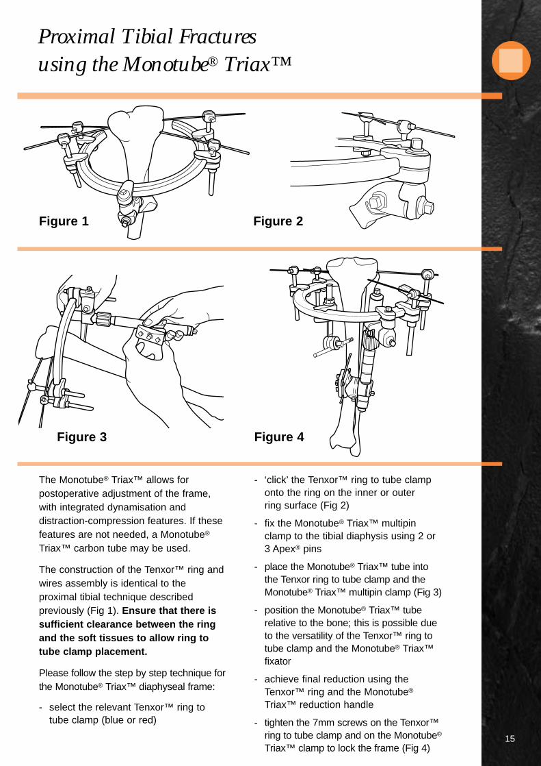
The Monotube® Triax™ allows forpostoperative adjustment of the frame,with integrated dynamisation anddistraction-compression features. If thesefeatures are not needed, a Monotube®
Triax™ carbon tube may be used.
The construction of the Tenxor™ ring andwires assembly is identical to theproximal tibial technique describedpreviously (Fig 1). Ensure that there issufficient clearance between the ringand the soft tissues to allow ring totube clamp placement.
Please follow the step by step technique forthe Monotube® Triax™ diaphyseal frame:
- select the relevant Tenxor™ ring totube clamp (blue or red)
- ‘click’ the Tenxor™ ring to tube clamponto the ring on the inner or outerring surface (Fig 2)
- fix the Monotube® Triax™ multipinclamp to the tibial diaphysis using 2 or3 Apex® pins
- place the Monotube® Triax™ tube intothe Tenxor ring to tube clamp and theMonotube® Triax™ multipin clamp (Fig 3)
- position the Monotube® Triax™ tuberelative to the bone; this is possible dueto the versatility of the Tenxor™ ring totube clamp and the Monotube® Triax™fixator
- achieve final reduction using theTenxor™ ring and the Monotube®
Triax™ reduction handle
- tighten the 7mm screws on the Tenxor™ring to tube clamp and on the Monotube®
Triax™ clamp to lock the frame (Fig 4)
Figure 3 Figure 4
Figure 1 Figure 2

Frames
16
1 2
3 4

17
5 6
FRAME COMPONENTS
1 2 3 4 5 6
Carbon Ring 1 1 1 1 1 1K-wires 3 2 3 3 3 2Wire Post 6 4 6 6 6 4Pin Post - - - 1 - 1Ring Clamp 6 6 6 7 6 5Hoffmann® II Rod to Rod 8 4 3 5 6 -Hoffmann® II Pin to Rod 6 5 3 1 - -Hoffmann® II Multipin Clamp - - - 1 2 -Hoffmann® II Post - - - 2 3 -Ring to tube Clamp - - - - - 1Triax™ Blue - - - - - 1Half Apex® Pins 6 3 3 3 3 3Transfixing Apex® Pins - 1 - - - -Hoffmann® II Rods 6 5 2 3 3 -
General Recommendations
18
K-wires are extremely sharp andshould be handled with care. Eyeprotection when using K-wires isrecommended.
K-wires should be placed to allow themaximum possible angle between thetwo outermost wires without damagingimportant soft tissue structures.
Ensure that all components are fullyopen (unscrewed) before frameassembly.
Positioning the ring above (below) thewires when treating a proximal (distal)fracture is possible but it makes theattachment of the Hoffmann® IIcouplings to the posts more difficult.
Place the wire and pin posts so thatthe 7mm screw is accessible.
Wires may be removed from the wirepost by depressing the tongue and‘unclicking’ the wires.
To gain extra height on the ring, thering clamp can be inverted (nut ontop).
Tighten the ring clamps completelybefore tensioning the wires. Theclamp will not slide on the ring andthe wire post will not move up ordown.
When tightening the 13mm nut on thering clamp, use the ring to applycounter force.
Minimum wire length required fortensioning is 70mm
Tighten the 7mm square head screwof the wire post until slightdeformation of the wire is visible.
Keep the wire tensioner parallel to thewire when tensioning.
DO NOT use the wire tensioner toapply counter force. When tighteningthe 7mm screws use the stabilisationwrench.
DO NOT ‘click’ the Hoffmann® IIcouplings on the 2 small stops of thewire post.
The Tenxor™ Fixator System is compatible with the Hoffmann® II Fixator
System and the Monotube® Triax™ Fixator System, please see the
relevant brochures for details.
The Tenxor™ Fixator System is compatible with all 4mm, 5mm and 6mm
Apex® pins, please see the Apex® Brochure for details.

Products & Instruments
19
Cat. No. Description
4936-0-015 Open Ring 150mm
4936-0-018 Open Ring 180mm
4936-0-021 Open Ring 210mm
4936-2-010 Ring Clamp
4936-2-040 Wire Post
4936-2-030 Pin Post
Ring to Monotube® Triax™ Tube Clamp
4936-2-920 Ø20mm (Blue)
4936-2-925 Ø25mm (Red)
Kirschner Wires
Diameter Length
5101-1-450 1.5mm 450mm
5101-2-450 2.0mm 450mm
Kirschner Wires with Olive
Diameter Length
5118-1-320 1.5mm 450mm
5118-1-340 2.0mm 450mm
Tenxor™ Instruments
4936-9-010 Wire Tensioner
4936-9-020 Cutting and Bending Pliers
4936-9-035 13mm Quick Capture Spanner Wrench
4936-9-040 Split Wire Sleeve
4936-9-050 Stabilisation Wrench
4936-9-060 7mm T Wrench
4936-9-070 7mm Cardan Wrench
5054-8-009 7mm Spanner Wrench
4936-9-900 Storage & Sterilisation Case
Stryker®, Hoffmann®, Hoffmann® II, Apex®, Monotube®, Triax™, Compact™ and Tenxor™ are trademarks of Stryker Corporation.Hoffmann®II Swiss Patent Application: 01-709/94-3. Other Patents Pending. * Patents: EU 385,929; 374,093; Canada 1,193,506; U.S. 5,160,335 and 5,207,676.** Swiss Patent Application: 02-709/94-3. Other Patents Pending. *** Patents: EU 230,856; Swiss CH 671,150; U.S. 4,978,350.†Data on file at Stryker® Howmedica Osteonics USA.

Manufacturing location5 chemin des AulxCH-1228 Plan-les-OuatesGeneva, SwitzerlandTel: 00 41 22 884 0111Fax:00 41 22 884 0199
Cat No: 5075-3-001
© 2001 Stryker Corporation. All rights reserved.1101
MANUFACTURER:
Unilateral frame system designed to handle a wide variety of fracturesand limb-lengthening applications. This simple, colour-coded systemoffers both dynamic and carbon tubes for individualised performanceand economy. True simplicity, versatility, and economy.
Modular frames which allow for true independent pin placement.Completely compatible with Original Hoffmann® components, thisnew system improves flexibility and ease-of-use, while enhancingframe economics through minimal componentry. It’s external fixationwith a “snap.”
Designed to complement the anatomy of the distal radius by allowing independentmovement of its clamps in multiple planes. Standard unilateral or bi-lateral bridgingframes for intra-articular fractures and peri-articular non-bridging frames for extra-articular fractures. Fully compatible with the Hoffmann® II System, based on aspring-loaded snap-fit mechanism that improves flexibility and ease-of-use.
The DJD II is a Dynamic Elbow Joint Distractor. Fully compatible withthe Hoffmann® II Compact™ System, it is designed to treat post-traumatic elbow stiffness as well as acute elbow trauma cases.
The Tenxor™ System is a hybrid system providing advanced technologyand ease of application. Fully compatible with Hoffmann® II andMonotube® Triax™, based on a spring-loaded, snap-fit mechanism thatimproves flexibility and ease of use.
Every Fixator incorporates the high quality pin-to-bone interfaceprovided by Apex® Pins. The Apex® Pin cuts more sharply with lesstorque, friction and heat upon insertion improving purchase whileminimising the risk of pin tract problems.† Available in self-drilling andblunt tip designs, only from Stryker® Howmedica Osteonics!
E X T E R N A L F I X A T I O N S Y S T E M
onotube® TRIAX™
®
™CompactEXTERNAL FIXATION SYSTEM
*
**
***


