12
FOUR NOZZLES VACUUM FILLING MACHINE TENCO s.r.l. Via Arbora 1 16030 Avegno (GE) Italia tel +39-0185-79556 - fax +39-0185-79412 ww.tenco.it - [email protected] Technical handbook

��
�����������
�
��� ����������������� ������� �����������������
FOUR NOZZLES VACUUM FILLING MACHINE
�
�
�
�
TENCO s.r.l. Via Arbora 1
16030 Avegno (GE) Italia tel +39-0185-79556 - fax +39-0185-79412
ww.tenco.it - [email protected]
Technical handbook
��
�����������
�
��� ����������������� ������� �����������������
SUMMARY � EC Declaration of Conformity pag.3 1 GENERAL DIRECTIONS AND INSTRUCTIONS pag.4 1.1 Foreward pag.4 1.2 Description of equipment pag.4 1.3 Use pag.4 1.4 Technicale Features pag.4 1.5 Customer's responsibility pag.4 1.6 Connection and start-up pag.4 1.7 Safety instructions pag.4 1.8 Direction for use pag.4 1.8.1. Start-up pag.4 1.8.2. Stopping and emergency procedures pag.4 2 INSTALLATION AND DIRECTIONS FOR USE pag.5 Drawings pag.6 3 CLEANING AND MAINTENANCE pag.7 4 DIAGNOSTIC pag.7 4.1. Possible troubles while Enolmaster running pag.7 4.2 Troubleshooting pag.7 5 REFERENCE STANDARDS pag.8 6 WARRANTY pag.8 MIGNON SET INSTALLATION pag.9 MOTOR FILTER INSTALLATION pag.10 SPARE PARTS - DRAWING pag.11

��
�����������
�
��� ����������������� ������� �����������������
EC DECLARATION OF CONFORMITY
The undersigned:
TENCO s.r.l. Via Arbora 1 -16030 Avegno (GE) Italy-
Declares, on its own responsibility, that the new machine Mod. ENOLMASTER Serial number Building year 2008 described here below: "vacuum filling machine 4 nozzles" complies with the European Regulations about Safety of home equipment EUROPEAN REGULATION EN 60335-1 Name: Giuseppe Tenco Position: Sole Director Place and date : Avegno,. Signature:
��
�����������
�
��� ����������������� ������� �����������������
CHAPTER 1 - GENERAL DIRECTIONS AND INSTRUCTIONS 1.1 FOREWARD Before using Enolmaster, carefully read these directions for use, using the table enclosed. Make sure that voltage shown on the data plate -to be found on the bottom- corresponds to your home supply. 1.2 DESCRIPTION OF EQUIPMENT Enolmaster is a professional vacuum filling machine for the filling of approx. 600 bottles/hour. 1.3 USE This equipment is to be used with wine, oil, tomato sauce, spirits, fruit juices and thick products. NOTE: Products with more than 20% alcohol content could damage Enolmaster. Therefore, in this case, we recommend to request the model P9921 (equipped with pyrex recovery vessel). In case the machine is used with the filter, please request TANDEM PROFESSIONAL mod. P9915 (equipped with pyrex filter holder). Also, if Enolmaster is employed to fill sugary liquors or products like balsamic vinegar, the oil-filled air filter must be employed to avoid damage to the machine vacuum pump; this accessory is not part of the standard supply and, if necessary, it must be ordered directly from the manufacturer. Tenco s.n.c. shall not be held responsible in case of malfunctioning of Enolmaster when the machine is operated to fill products as those described above, without using the above specified accessories. 1.4 TECHNICAL FEATURES Refer to the label on the machine. 1.5 CUSTOMER'S RESPONSIBILITY Installation of filling machines in premises complying with all applicable sanitary regulations and fitted with certified electrical systems shall be responsibility of the user. 1.6 CONNECTION AND START-UP Place the equipment on a suitable surface. Ensure the main switch is on OFF position and connect power cable. 1.7 SAFETY INSTRUCTIONS Do not spill liquids into slots. Do not open the machine, and, if so, only after power disconnection 1.8 DIRECTIONS FOR USE
1.8.1. Start-up: this equipment is started by acting on the relevant control or main switch. 1.8.2. Stopping and emergency procedures: emergency stop is activated by sectioning the mains
through electrical plug removal. IMPORTANT: if you switch engine off while using Enolmaster, it’s absolutely necessary, before switching it on again, to raise knob “S” until there is no vacuum. The same operation must be performed to remove the bowl cover.
��
�����������
�
��� ����������������� ������� �����������������
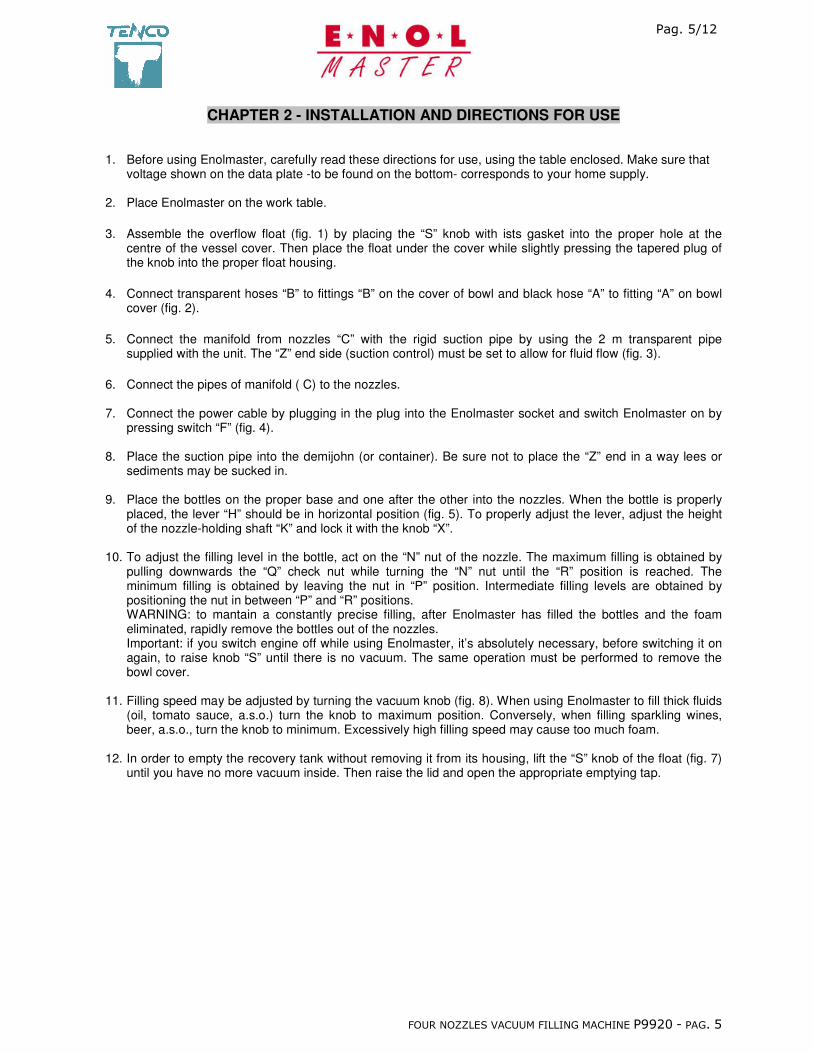
CHAPTER 2 - INSTALLATION AND DIRECTIONS FOR USE
1. Before using Enolmaster, carefully read these directions for use, using the table enclosed. Make sure that
voltage shown on the data plate -to be found on the bottom- corresponds to your home supply. 2. Place Enolmaster on the work table. �3. Assemble the overflow float (fig. 1) by placing the “S” knob with ists gasket into the proper hole at the
centre of the vessel cover. Then place the float under the cover while slightly pressing the tapered plug of the knob into the proper float housing.
�4. Connect transparent hoses “B” to fittings “B” on the cover of bowl and black hose “A” to fitting “A” on bowl
cover (fig. 2). �5. Connect the manifold from nozzles “C” with the rigid suction pipe by using the 2 m transparent pipe
supplied with the unit. The “Z” end side (suction control) must be set to allow for fluid flow (fig. 3). �6. Connect the pipes of manifold ( C) to the nozzles. 7. Connect the power cable by plugging in the plug into the Enolmaster socket and switch Enolmaster on by
pressing switch “F” (fig. 4). 8. Place the suction pipe into the demijohn (or container). Be sure not to place the “Z” end in a way lees or
sediments may be sucked in. 9. Place the bottles on the proper base and one after the other into the nozzles. When the bottle is properly
placed, the lever “H” should be in horizontal position (fig. 5). To properly adjust the lever, adjust the height of the nozzle-holding shaft “K” and lock it with the knob “X”.
10. To adjust the filling level in the bottle, act on the “N” nut of the nozzle. The maximum filling is obtained by
pulling downwards the “Q” check nut while turning the “N” nut until the “R” position is reached. The minimum filling is obtained by leaving the nut in “P” position. Intermediate filling levels are obtained by positioning the nut in between “P” and “R” positions. WARNING: to mantain a constantly precise filling, after Enolmaster has filled the bottles and the foam eliminated, rapidly remove the bottles out of the nozzles. Important: if you switch engine off while using Enolmaster, it’s absolutely necessary, before switching it on again, to raise knob “S” until there is no vacuum. The same operation must be performed to remove the bowl cover.
11. Filling speed may be adjusted by turning the vacuum knob (fig. 8). When using Enolmaster to fill thick fluids
(oil, tomato sauce, a.s.o.) turn the knob to maximum position. Conversely, when filling sparkling wines, beer, a.s.o., turn the knob to minimum. Excessively high filling speed may cause too much foam.
12. In order to empty the recovery tank without removing it from its housing, lift the “S” knob of the float (fig. 7)
until you have no more vacuum inside. Then raise the lid and open the appropriate emptying tap.

��
�����������
�
��� ����������������� ������� �����������������
��
����� �����
�
��� ����������������� ������� ��������������� �
CHAPTER 3 - CLEANING AND MAINTENANCE No maintenance is required, except for cleaning and sanitizing before and after use. In order to clean equipment, after rising, isolate the equipment by sectioning power supply. The recovery tank can be washed with water alone or, in case oil was bottled, with dishwashing liquid. When handling different products, kits supplied by Tenco s.n.c. (Oil kit, Jar kit, Tomato kit, ecc.) are recommended. To replace the nozzles, rotate the “T” handle by half turn and remove the “U” pin (fig. 9). Open the two plastic elements of the lever and disconnect the entire assembly fron the rod. Then disengage the spring. To install others nozzles, follow the above instructions in the opposite way.
CHAPTER 4 - DIAGNOSTICS
4.1 POSSIBLE TROUBLES WHILE ENOLMASTER IS RUNNING In case of malfuncioning and/or breakdown/failure, set the main switch on OFF and immediately unplug the unit. Any operation on electrical parts inside the case shall be performed by authorised and specifically trained personnel. Warning: hazardous voltage can harm you during maintenance on energised apparatus. Warning: any operation on equipment shal be performed after releasing any remaining pressure and disconnecting from mains (see chap. 2- point 9). If things go wrong, check the table below. If none of the solutions listed gives a positive result, get in touch with our authorized retailer. 4.2 TROUBLESHOOTING
Troubles Causes Solutions Engine doesn’t start 1) no electricity supply
2) plug not connected 3) the fuses of the power socket may
have burnt out (fig. 4) 4) the whole device is in a vacuum
1) check 2) check 3) disconnect the power cable and remove
them by unscrewing the fuse block in the socket by one quarter of turn. Check the fuse conditions and if necessary replace them (1,6 A 250 V)
4) raise knob “S” of the float for few seconds (fig. 7)
Liquid doesn’t go into the bottle
1) engine off 2) the bowl cover is improperly closed 3) the speed adjuster is improperly
set to minimum 4) the nozzles are clogged 5) the suction pipe is resting on the
demijohn bottom 6) the bottle mouth edge is chipped 7) the rubber ring of the closing cone
is broken 8) the nozzles fail to slide properly
1) check 2) close it well by pushing downwards 3) turn the knob clocwise to maximum (fig. 8) 4) check whether the “A” suction hole is
obstructed. Blow into the nozzle from the side of the “B” foam recovery hose, while raising the “E” closing cone. Further check that the “C” fluid outflow hole is not clogged by blowing from the side of the “D” suction pipe, while still raising the “E” closing cone. (fig. 13)
5) adjust the “Z” end side to mantain the suction pipe at a certain distance from the bottom
6) replace the bottle 7) replace it 8) check the 2.02 and 2.06 o-rings. (see
exploded drawing). Grease nozzles with vaseline oil (see 4.03 on the exploded drawing)
��
�����!�����
�
��� ����������������� ������� ���������������!�
CHAPTER 5 - REFERENCE STANDARDS Statutory regulations - Decree Law n° 615, dd. 12/11/1996 - Transposition of the Community Directive n° 89/336/EEC on
Electromagnetic Compatibility (EMC). - Law n° 791, dd. 18/10/1977 - Transposition of the Community Directive (DB) (73/23/EEC) on electrical
equipment safety assurance. - Decree Law n° 626, dd. 25/11/1996 - Transposition of the directive 93/68/EEC on CE marking for electrical
equipment to be used within specific voltage ranges. Voluntary regulations - EN 60335-1 (1989 - Safety on household elecrical appliances and similar appliances. - General provisions (IEC 335-1/1/1976). - European Directive on Electromagnetical Compatibility n° 89/336/EMC
CHAPTER 6 - WARRANTY The Manufacturer guarantees that the equipment to which these documents refer has been tested and that the established test results have been achieved. The warranty period shall last 12 months, beginning on the date of delivery of the equipment (as indicated in the transport document), except as otherwise agreed upon between the Parties. The Manufacturer guarantees the equipment to be free from defects in materials and workmanship. Damage deriving from transport not carried out by transport means of the Manufacturer, from improper maintenance, failure of electrical equipment, improper use or negligence, or adjustments/repairs carried out by service personnel not duly authorized by the Manufacturer or in any case beyond the control of the Manufacturer shall NOT be covered by this warranty. The warranty cannot be transferred by the initial owner of the product to third parties. During the applicable warranty period, the Manufacturer will repair or replace free of charge any warranted parts that prove defective. For these operations to be carried out, the equipment shall have to be transported to the Manufacturer, who shall not be responsible for any transport charges. The Manufacturer shall not repair the equipment during the warranty period at the Customer's premises, except as otherwise agreed upon between the Parties. After the above specified period, this warrantee shall expire The Manufacturer shall in no event be liable for any direct, consequential, incidental, indirect or special damages caused to people or property by original defects of the equipment, equipment failure, or subsequent forced stoppage in the use of the equipment. The Manufacturer shall not be liable for filling defects if, at the time of equipment construction, the Client has failed to provide a full sampling of containers and products required in order to carry out the necessary tests.
��
�����������
�
��� ����������������� ������� �����������������
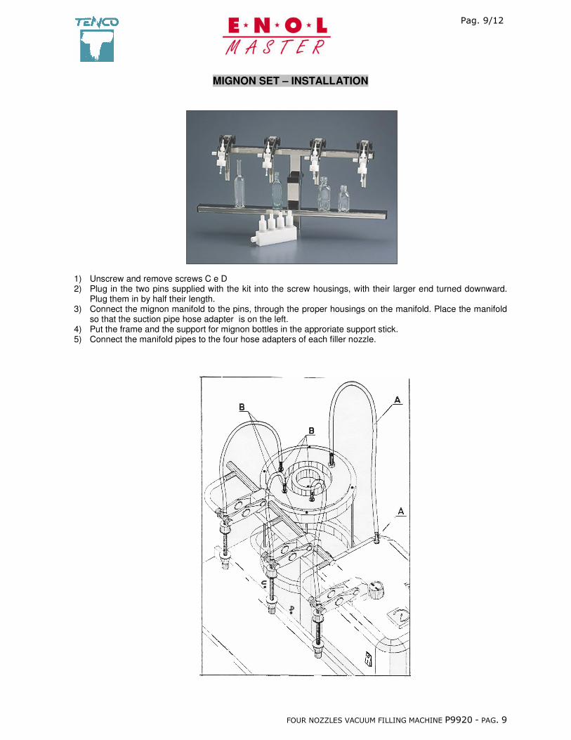
MIGNON SET – INSTALLATION
1) Unscrew and remove screws C e D 2) Plug in the two pins supplied with the kit into the screw housings, with their larger end turned downward.
Plug them in by half their length. 3) Connect the mignon manifold to the pins, through the proper housings on the manifold. Place the manifold
so that the suction pipe hose adapter is on the left. 4) Put the frame and the support for mignon bottles in the approriate support stick. 5) Connect the manifold pipes to the four hose adapters of each filler nozzle.

��
������������
�
��� ����������������� ������� ������������������
MOTOR FILTER INSTALLATION This type of filter is used when the filling machine is employed for filling fluids with a high alcohol and sugar content, such as balsamic vinegar and the whole range or products releasing vapors that could damage the Enolmaster pump. We recommend to order the filter directly from the manufacturer, if required, for it is not supplied with the filling machine. Tenco s.n.c. shall not be liable for any problems that could arise with Enolmaster operation, caused by its use without said filter when employed for the filling of products as described above. Installation: The filter must always be mounted in a vertical position. A max 30° angle is allowed. - connect the rubber junction gasket with the wording «al motore» (to motor) to rubber junction gasket «A» - connect the rubber junction gasket with the word «vaso» (tank) to rubber junction gasket «C» Note: lubricant oil for enologic use is always required. Do not allow it to exceed the level indicated in the oil sump.
VASO
MOTORE
Fig: 1 Fig. 2
c
��
������������
�
��� ����������������� ������� ������������������
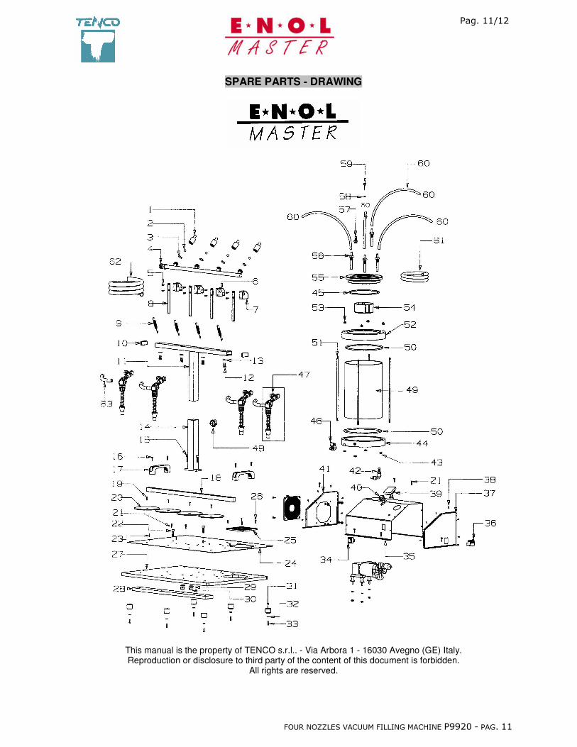
SPARE PARTS - DRAWING �
This manual is the property of TENCO s.r.l.. - Via Arbora 1 - 16030 Avegno (GE) Italy. Reproduction or disclosure to third party of the content of this document is forbidden.
All rights are reserved.
��
������������
�
��� ����������������� ������� ������������������
�
�
��
��
�
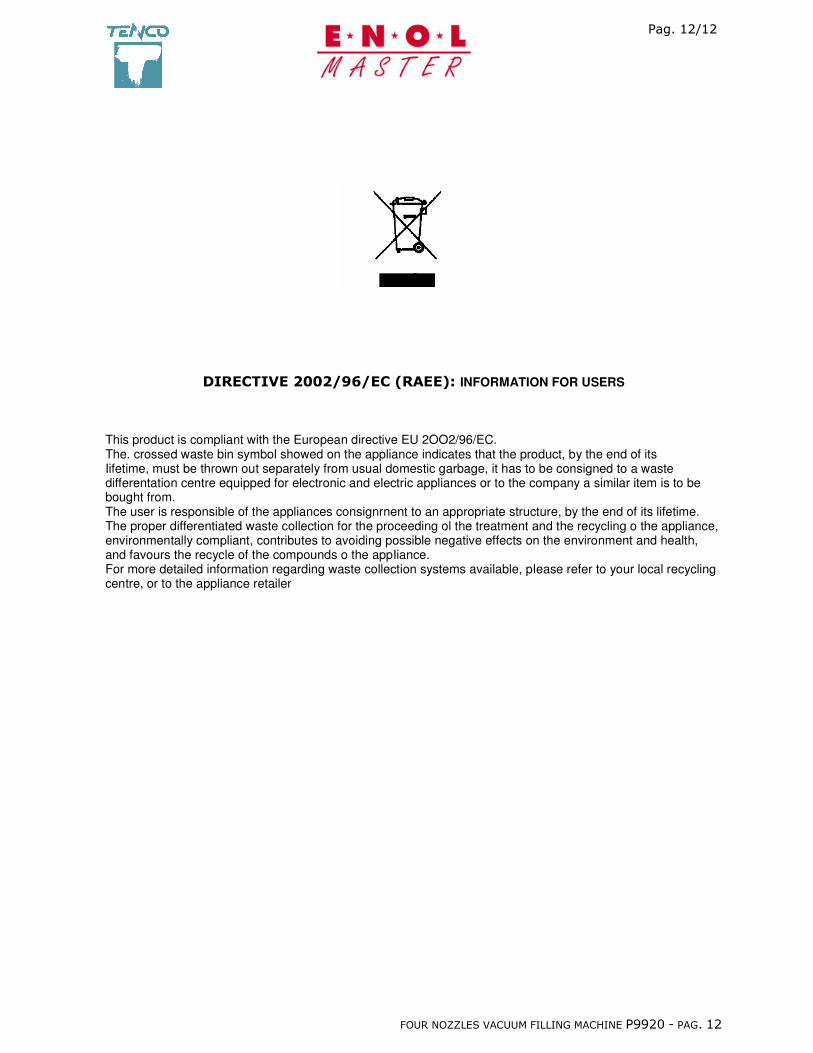
������������� ������������INFORMATION FOR USERS�
This product is compliant with the European directive EU 2OO2/96/EC. The. crossed waste bin symbol showed on the appliance indicates that the product, by the end of its Iifetime, must be thrown out separately from usual domestic garbage, it has to be consigned to a waste differentation centre equipped for electronic and electric appliances or to the company a similar item is to be bought from. The user is responsible of the appliances consignrnent to an appropriate structure, by the end of its lifetime. The proper differentiated waste collection for the proceeding ol the treatment and the recycling o the appliance, environmentally compliant, contributes to avoiding possible negative effects on the environment and health, and favours the recycle of the compounds o the appIiance. For more detailed information regarding waste collection systems available, pIease refer to your local recycling centre, or to the appliance retailer


