48
AZKOYEN Medios de Pago, S.A TEL.: +34 948 709 709 Avda. San Silvestre, s/n Fax: +34 948 709 709 31350 Peralta (Navarra) Spain www.azkoyen.com Technical Information: T3 HOPPER
AZKOYEN Medios de Pago, S.A TEL.: +34 948 709 709 Avda. San Silvestre, s/n Fax: +34 948 709 709 31350 Peralta (Navarra) Spain www.azkoyen.com
Technical Information:
T3 HOPPER

2
07 - 2009
CONTENTS INDEX 1 INTRODUCTION 4
2 INSTALLATION AND STARTING UP 6
3 TECHNICAL CHARACTERISTICS 11 3.1 ENVIRONMENT AND CLIMATIC CONDITIONS 11 3.2 MECHANICAL CHARACTERISTICS 11
3.2.1 Dimensions 11
3.2.2 Weight 12
3.2.3 Range of coins 12
3.2.4 Capacity of coins 13
3.2.5 Locating the reloading and exit areas of the coins 14
3.2.6 Ergonomic for the user 14
3.3 ELECTRICAL CHARACTERISTICS 16 3.3.1 Power supply and current 16 3.3.3 Pin out 19
3.4 ELECTRONIC CHARACTERISTICS 21 3.4.1 Control board. T3 Cctalk. 21 3.4.2 Control board. T3 parallel. 23 3.4.3 Detection of coin levels 24 3.4.4 Detection of exit of coins 24 3.4.5 Double count 25 3.4.6 Identification of coin 25 3.4.7 Current sensor 25
4 HOW IT WORKS 26 4.2 PAYOUT OF COINS 26 4.3 SPEED OF EXTRACTION 26 4.4 DETECTION OF THE PRESENCE OF COINS 27 4.5 DETECTION OF LEVELS 27 4.6 SECURITY AND CONTROL DEVICES 27
5 COMMUNICATION PROTOCOLS 30 5.1 CCTALK® SERIAL PROTOCOL 30
5.1.1 Cctalk Configuration address 30
5.1.2 Configuration of the coin type 31
5.2 PARALLEL PROTOCOL 31
5.2.1 Configuration of the working mode 31
5.2.2 Working modes 32
5.2.3 Indications of the status LEDs 33

3
07 - 2009
6 SERVICE OPERATIONS 35 6.1 DISASSEMBLY AND ASSEMBLY 35 6.2 CLEANING OF THE OPTIC SENSOR ON THE COIN EXIT 37 6.3 MECHANICAL CONFIGURATION OF THE CHANGE RETURN RANGE 38 6.4 ADJUSTING THE MAXIMUM AND MINIMUM LEVELS IN THE HOPPER 42
7 TOOLS 43 7.1 PROGRAMMING TOOLS. 43 7.1.1 HEUS user application 43 7.1.2 TL20 Tool 43 7.2 AZKOYEN SIMULATION TOOLS 44 7.2.1 Cctalk Manager 44
8 NORMS 46

4
07 - 2009
1 INTRODUCTION
The coin T3 hopper has been designed to meet the technical specifications for the payment of
coins that are required by the different applications of the automatic vending of services or
products. The principle characteristics on which its design is based are determined by the
following payout needs: high capacity, security of transaction, speed of the payment for
demanding sectors such as: parking, ticketing and change, among others.
The T3 hopper range is comprised of different models and configurations depending on the
capacity of the hopper, communication protocol and controlling one or two coins in the same
device. The different types of T3 hopper with details on their characteristics and modes of
working are covered in this technical manual.
We have worked closely with the manufacturers of equipment and the end users of these
systems on the design of the T3 hopper, end users like maintenance personnel, also studying
the main characteristics of the products available at present and taking into account their
shortcomings. On the developing this new hopper, we have been able to improve their
performance, as well as adding technical solutions for the optimisation of the capacity and
speed of payment so as to facilitate the integration in the systems within of the application.
ATTENTION: Read this technical manual carefully
before installing or carrying out any operation on the T3
hopper.
ATTENTION: There are moving mechanisms inside the
coin hopper that may cause personal injury. If
manipulating the T3 hopper, always make sure that it is
disconnected.

5
07 - 2009
With respect to the communication protocol used by the master, there are two models of T3
hopper:
• T3 parallel
• T3 Cctalk
With respect to the capacity of the storage of coins, there are two options:
• T3, single bowl
• T3 x 2, double capacity storage
The T3 hopper incorporates advanced coin detection systems and payment management,
which makes them one of the most secure hoppers in the market.

6
07 - 2009
2 INSTALLATION AND STARTING UP
For correct installation and starting up, the following points must be checked:
1) Be sure that the model of Hopper corresponds with the type of interface in the
machine or system, that is, if it works in parallel or with serial communication Cctalk
®. This information is available on the label of the hopper, as shown in figure 2.
Figure 1: label with the characteristics
2) Disconnect the machine or system from the mains power supply.
3) Check the position and the type of connector in the machine, to determine if the T3
hopper connecter should be fitted at the front or back. The position of the main
connector on the T3 may be changed with a simple operation.
4) Be sure the type of coin that is to be paid out from the hopper corresponds with the
configuration of the hopper. There are different track configurations for the
Model T3 HOPPER CCT/CM/EU
Reference 411xxxx-x
Interface CCTALK®
Connector Position STANDARD
Coinage Ø18- Ø26 (2c to 2€)
Program €
Date 04/09/09
ATTENTION: Is very important carry out the installation of the T3 hopper with the machine disconnected from the mains to avoid producing any electrical damage.

7
07 - 2009
diameters and thicknesses of the coins. For the Euro currency there is one unique
configuration that covers the whole range of coins, except the one cent coin.
5) If the machine is fitted with a base plate for the hopper, place the hopper on the
base so that the gaps coincide with the tabs on the T3, then slide the hopper firmly
into the base until you hear the clips activate.
6) Although it is recommended to always use the base plate for correct fixture and
connection, in the case that the machine does not have one, use the fixtures in the
machine to install the hopper. Special care should be taken with the connector to
make the connections physically coincide.
7) If the T3 is a ccTalk® model, it will be necessary to configure the address of the
hopper within the system. For this, three different methods may be used to configure
the hopper addresses:
i. Hardware configuration, by means of the three addressing lines present at the
main connector. By default, the hopper is assigned inside the ccTalk bus with
the address number 3. When more than one hopper is used it is needed the
assignation of addresses for the rest of devices connecting one or more selection
lines to the positive connection +Vs.
Pinout ccTalk connector
Pin Function
1 0V (GND)
2 NC
3 NC
4 Sel. Adr.1 (LSB)
5 DATA (Cctalk)
6 NC
7 NC
8 Sel. Adr.2
9 +Vs (+24V)
10 NC
11 NC
12 Sel. Adr.3 ( MSB)

8
07 - 2009
Addresing by hardware connections at the main connector
● Conect to +Vs (24V, pin 9)
Tabla 3: connections for hardware address setup
ii. Dispswitch configuration, through the dipswitches located on the main board.
Figure 2: Details of the location of the circuit board
ccTalk address Sel. Adr.3 Sel.Adr.2 Sel.Adr.1
3 4 ● 5 ● 6 ● ● 7 ● 8 ● ● 9 ● ●
10 ● ● ●

9
07 - 2009
Table 2: Configuration of the type of coin
iii. Address configuration by ccTalk commands Address Change [251] and
Address Random [250].
8) In T3 models using two coins, the coins combination must be configured as by the
Table 4.
Tabla 4: coins combinations for double coin models
9) In parallel models, configure the working mode by means of the dipswitches,
depending on the logic used: positive, negative or pulse mode.
10) If it is considered necessary, adjust the position of the coin level sensors to adapt to
the needs of the system. There are two holes for the empty detection sensors and
four for the full detection sensors (Figure 3).

10
07 - 2009
Figure 3: Position of the level sensors
11) Fill the hopper.
12) Before connecting the machine to the mains, carry out a visual inspection to
determine that there is no interference with either the entry or exit of the coins.
13) Switch on the mains power. The hopper will be ready to work. In the Parallel T3
hopper there is a status LED, in green, to indicate that there is no error that and it is
working normally.
Full sensors
Empty sensors

11
07 - 2009
3 TECHNICAL CHARACTERISTICS
3.1 ENVIRONMENT AND CLIMATIC CONDITIONS
For reasons of safety, this equipment, once installed, should not be directly accessible to the user, being situated at a minimum distance of 10 mm from any electrical part of the hopper and any metal parts. Inclination It should not be over 3º inclination in any of its axes. Range of temperatures Working: 0 to + 60ºC Storage: - 20 to + 60ºC Humidity levels Maximum 95% relative humidity without condensation
3.2 MECHANICAL CHARACTERISTICS
3.2.1 Dimensions
Figure 4: Dimensions
Table 3: Total dimensions
A (mm) B (mm) C (mm)
T3 226 ± 1 126.5 ± 1 285.5 ± 1
T3 x 2 226 ± 1 253 ± 1 285.5 ± 1

12
07 - 2009
3.2.2 Weight Empty T3 hopper, single: 1,850 Kg Empty T3 hopper, double: 1,950 Kg
3.2.3 Range of coins The T3 will allow the payment of any type of coin within the following parameters:
Table 4: Range of coins
Range of coins The total range of coins is covered with three mechanical configurations. The standard
configuration allows the payment of a very wide range of coins; within the Euro zone all the
coins except the 1 cent.
Moreover, there are two additional configurations that complete the total payout range, one for
coins of smaller diameters and another for coins of larger diameters.
For more information about of the different mechanical configurations, consult section 6.3 MECHANICAL CONFIGURATION FOR THE RANGE OF COINS.
Min. Max.
Diameter (mm) 16.25 32.5
Thickness (mm) 1.2 3.2
Diameter (mm)
8 16.25 18 22 24 26 32,5
1,5
3,2
1,2
STANDARD Configuration
LARGE coin Configuration
SMALL coin Configuration
Th
ickn
ess

13
07 - 2009
Configurations of the range of coins
Figure 5: Diagram of range of coins by CONFIGURATION
( * ) available soon
Range of coins for the Standard configuration M
Table 5: Range of coins, STANDARD CONFIGURATION M
3.2.4 Capacity of coins The information below indicates the average capacity of coins depending on the configuration of
the hopper.
SINGLE BOWL DOUBLE BOWL
* example capacities for the 1 € coin Table 6: Capacity of coins by configuration
Min. Max.
Diameter (mm) 18 26
Thickness (mm) 1.5 3.2
SINGLE BOWL DOUBLE BOWL 1.550 2.750
Diameter 24,00 - 32,50 Thickness 1,50 - 3,20
( * ) XL
Diameter 18,00 - 26,00 Thickness 1,50 - 3,20M
Diameter 16,25 - 22,00 Thickness 1,20 - 3,20 ( * ) XS
GENERAL RANGE OF COINS
1c NO

14
07 - 2009
3.2.5 Locating the reloading and exit areas of the coins Reloading area. The reloading area of the coins is the total surface area of the upper part of
the T3 hopper. This way, integrating the hopper within the machine is more flexible for the
location of the coin channels.
Exit of coins. For a better controlled exiting of the coins, the size of the payout window is
reduced. It has been designed so that the coins slide out horizontally and reach the exterior in a
stabilised way, facilitating the transport of the coin towards the refund slot on the machine.
Figure 6: Location of the entry and exit of coins
3.2.6 Ergonomic for the user Extraction points. The T3 hopper is designed to facilitate the extraction of the unit from its
base plate. There are two windows near the location of the main connector on the front and
back part (depending on the configuration of the connector) to insert one’s fingers and pull on
the unit.
Figure 7: Front extraction point and usage Points of transport. To facilitate the transport of the T3, there are different points by where the
Reloading area
Coin exit
15
07 - 2009
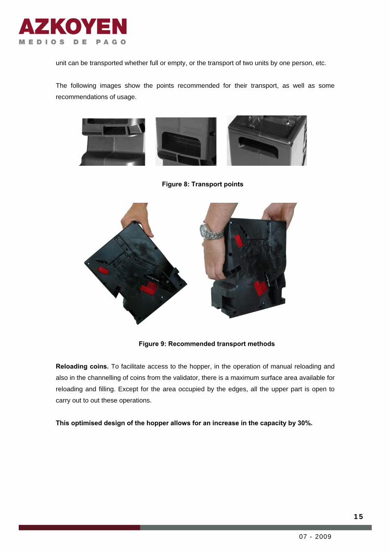
unit can be transported whether full or empty, or the transport of two units by one person, etc.
The following images show the points recommended for their transport, as well as some
recommendations of usage.
Figure 8: Transport points
Figure 9: Recommended transport methods Reloading coins. To facilitate access to the hopper, in the operation of manual reloading and
also in the channelling of coins from the validator, there is a maximum surface area available for
reloading and filling. Except for the area occupied by the edges, all the upper part is open to
carry out to out these operations.
This optimised design of the hopper allows for an increase in the capacity by 30%.
16
07 - 2009
3.3 ELECTRICAL CHARACTERISTICS
3.3.1 Power supply and current
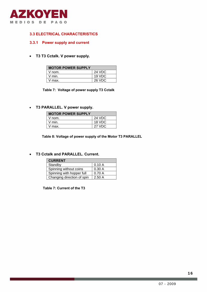
• T3 T3 Cctalk. V power supply.
MOTOR POWER SUPPLY V nom. 24 VDC V min. 19 VDC V max. 26 VDC
Table 7: Voltage of power supply T3 Cctalk • T3 PARALLEL. V power supply.
MOTOR POWER SUPPLY V nom. 24 VDC V min. 18 VDC V max. 27 VDC
Table 8: Voltage of power supply of the Motor T3 PARALLEL
• T3 Cctalk and PARALLEL. Current. CURRENT Standby 0.10 A Spinning without coins 0.30 A Spinning with hopper full 0.70 A Changing direction of spin 2.50 A
Table 7: Current of the T3

17
07 - 2009
3.3.2 Types of connectors There are two options for the type of connector used:
1. AZKOYEN Molex 2x6 way connector 2. Cinch 12 way connector
The most common connector is of the type Cinch male. The complementary connector is
mounted on the base plate.
A new connector has been developed to facilitate the connection to the machine in those
applications where it used to be necessary to have soldered connections. This connector is a
Molex 2x6 way. This connection has as the advantage that the machine may be wired up with
2x6 way ribbon cable and therefore be connected directly to the base of the hopper without the
need of solder.
1. AZKOYEN Molex 2x6 way connector The connection from the master to the T3 is made by means of a Molex 2x6 way female
connector located in the base plate of the hopper.
The hopper is connected to the base by means of a 2x6 way Plug & Play connector doted with
a mobile mechanism that means that it adapts to the connector of the position of the hopper
without damaging the connectors.
Figure 11: Base with Azkoyen connector and details of the front and back

18
07 - 2009
The connector that is recommended in the master, in the case of using the Azkoyen solution is
a Molex male 2x6 way connector size 2.54
Figure 12: Connectors Azkoyen 2. Cinch connector
Figure 10: Cinch connectors
Azkoyen connector in the base plate Connector recommended in the master Type Molex 2x6 female size 2.54 Type Molex 2x6 male size 2.54
Connector Cinch MKII Female 12 way Connector Cinch MKII Male 12 way

19
07 - 2009
Figure 13: Dimensions of the Cinch connector
3.3.3 Pin out Independently of the type of connector used, Cinch or Azkoyen, the number of pins and there
functions are remain the same.
T3 Cctalk
Table 10: Pin out T3 Cctalk
PIN FUNCTION
1 0V (GND)
2 NC
3 NC
4 Val. Address 1-LSB
5 DATA (Cctalk)
6 NC
7 NC
8 Val. Address 2
9 +Vs (+24V)
10 NC
11 NC
12 Val. Address 3 - MSB

20
07 - 2009
T3 Parallel
PIN FUNCTION
1 Pwr. Motor 0 volt.
2 Power supply Logic 0 volt.
3 uP Sensor Exit
4 IN1
5 Exit Security
6 Exit Sensor Full
7 Exit Sensor Empty
8 IN2
9 Pwr. Motor
10 Pwr. Logic
11 Exit Raw Sensor
12 IN3
Table 11: Pin out T3 parallel

21
07 - 2009
3.4 ELECTRONIC CHARACTERISTICS
There are two different control boards: one for the T3 with serial Cctalk ® interface and another for the model T3 parallel. Their connections and characteristics are described below. 3.4.1 Control board. T3 Cctalk. This is the main control board where the sensors and active components such as the motor,
encoder for position of the motor and level detectors are connected.
Furthermore, this board has of two groups of dipswitches that are used to set the configuration
of the working parameters of the unit. The optic sensors for counting of coins paid out are
located on the board.
1 – Connection PCB sensorisation 2 – Connection motor 3 – Connection motor encoder 4 – Connection Cctalk 5 – Connection level detectors of hopper 6 – Connection Programming and tools7 – Dipswitches, configuration of Cctalk addresses and working modes 8 – Dipswitches configuration of coin type
Figure 13: PCB T3 hopper Cctalk
Connection PCB sensorisation.
The sensorisation board with the magnetic parameters and with the data of diameters of the
coins on the track are connected to this connector. In the single coin T3 model, this sensor
stage performs a second count of the coins paid out. The T3 models with double coin,
implement an advance version of this sensor wich allows the coin ID by its magnetic and
physical characteristics.
Connection Cctalk Connection to the main external connector of the T3 hopper.
Connection level detectors of the hopper.
7 8
23 4 5
1
6
22
07 - 2009
This connection is for the optic sensors that measure the level of coins present in the hopper,
they detect the Minimum and Maximum levels of coins in the hopper. The position is
configurable to adapt to the capacity levels and the storage needs .
Connection programming and tools. This connection is for programming the firmware of the T3 hopper. The circuit board is governed
by a micro-controller with a flash memory that allows one to update the firmware by means of
the user tools. For this operation there is the web technical of Azkoyen Medios of Pago, S.A
with the application HeUs.
For reprogramming in the field you may use, in combination with the application HeUs, the
portable tool TL20.
The specification for this 6-pin connector is the following:
Pin Function 1 - 2 GND 3 RX 4 - 5 TX 6 +5V
Table 12: Pin out of the programming connector
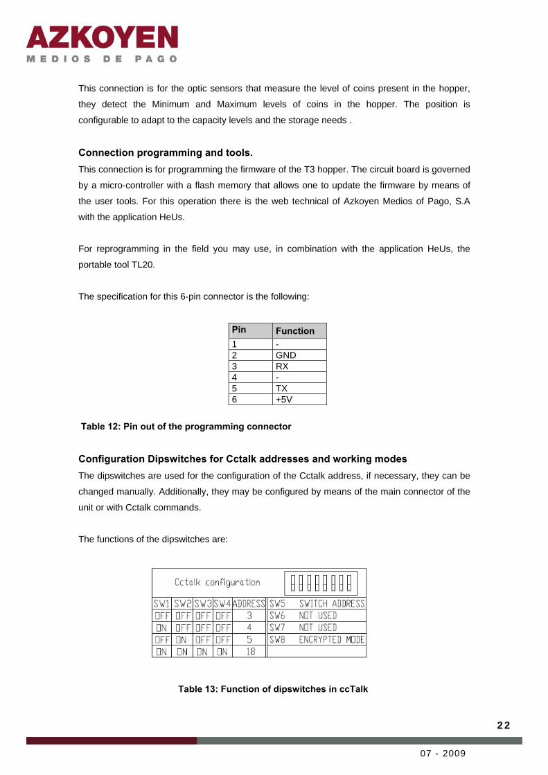
Configuration Dipswitches for Cctalk addresses and working modes The dipswitches are used for the configuration of the Cctalk address, if necessary, they can be
changed manually. Additionally, they may be configured by means of the main connector of the
unit or with Cctalk commands.
The functions of the dipswitches are:
Table 13: Function of dipswitches in ccTalk

23
07 - 2009
3.4.2 Control board. T3 parallel.
1 – Connection PCB sensorisation 2 – Connection motor 3 – Connection motor encoder 4 – Connection parallel 5 – Connection level detectors 6 – Connection programming and tools 7 – Dipswitches mode selection 8 – Status LEDs
Figure 14: PCB T3 hopper parallel
(See description of positions 1, 5 and 6 in the section 3.3.1 Control board T3 Cctalk)
Parallel connection The connection between the main external connector of the T3 hopper and the circuit board.
Mode selection dipswitches For the definition of the working mode, as well as being able to make a hardware configuration
using the entry lines IN1-IN3, you are able to establish the selection of the position of the
switches using the following table.
Table 14: Configuration of parallel working mode
1
2 3 4 5
6
7 8

24
07 - 2009
Status LEDs The LEDs on the control board show information about the present working status of the T3
hopper. There are 3 LEDs, that from left to right have the functions: Power supply (green),
Security (green) and Sensor (red).
Power supply – Indicates that the unit it is active
Security – In absence of errors it will be lit. When there is an error, the LED will
switch off and it will communicate the code through the Sensor.
Sensor- In standby it is switched off. When an exit of coin is detected it is activated
once. In communication of error mode, the LED is switched off, it informs the error
code using a number of flashes.
For more information on the status LEDs consult chapter 5.2.3 Indications of the status LEDs.
3.4.3 Detection of coin levels The detection of the level of coins in the hopper is done with two pairs of optic sensors, a
photodiode and a phototransistor.
The T3 hopper allows you to situate these barriers in any of the available positions, two for the
detection of the minimum level and four for the detection of the maximum level. The
approximate capacities are shown in following figure.
Figure 15: Capacity of coins detected with respect to the position of the sensor
3.4.4 Detection of exit of coins It is situated in the upper part of the extractor track, and is located on the control board. Its
function is to count the coins paid out and detect the possible breakdowns or attempts of
manipulation using optic sensors; this is carried out by software.
Approximate capacity of €1 1 – 35 coins. 2 – 75 coins. 3 – 700 coins. 4 – 1100 coins. 5 – 1550 coins.
Full
Empty
5 4 3 2 1
25
07 - 2009
3.4.5 Double count As well as the detection of the coin at the moment of payout, the T3 model of single coin
implements a previous stage of sensorisation of the magnetic and physical parameters to
previously read the values and therefore confirm the information obtained on exit detection.
3.4.6 Identification of coin The T3 model for 2 coin types is prepared with an advanced version of the Double Count
sensor that is capable of identifying the value of the coin at a previous stage. This system
measures the physical and magnetic characteristics of each coin and then contrasts it with the
data previously programmed.
3.4.7 Current sensor The current sensor detects, at all times, the current draw of the motor in the hopper. On
detecting a possible jam situation in the hopper, anti-jam measures can be activated that
consist in reversing the extraction mechanism. It tries to solve the matter by carrying out a
sequence of reverse cycles. If it is not possible to resolve the jam, the hopper informs this error
to the master, in both models, parallel and Cctalk.

26
07 - 2009
4 HOW IT WORKS
4.2 PAYOUT OF COINS The extraction system is based on an inclined plastic track laying flat where the coins are
caught and held by gravity and that it is activated by a motor. The lower part this track catches
the coins and positions them the cavities along the track in a way that they lay on their sides
and are transported in an upward movement towards the exit, situated in the front and highest
part of the hopper.
Figure 16: Extraction system Figure 17: Breakdown of the extraction system
The T3 receives the order from the master and carries out the payment, communicating the
execution of the order or of any error or incidence in the case of not achieving complete
payment.
The payment orders, and the way the incidents or events are communicated between the
hopper and the master, differ between the two types of hopper depending on whether they use
parallel or Cctalk serial protocol. For specification of the protocols consult chapter 5. Communication protocols.
4.3 SPEED OF EXTRACTION The speed of the payment of coins it is determined by the speed of the extraction system and
the diameter of the coin.
The T3 hopper is capable of paying out up to 4.5 coin/sec.

27
07 - 2009
4.4 DETECTION OF THE PRESENCE OF COINS At the previous sensorisation stage, and depending on whether the model manages one or two
coin types, the necessary measurements of the parameters and characteristics of the coins that
are being transported the track are done. The parameters obtained by means of the magnetic
and optic sensor are contrasted with the data base in the hopper to identify the value when
working with two types of coins. In this way the hopper knows what type of coin occupies each
position on the track and may determine the posterior action related with the finalisation of the
payment, with respect to the payout value requested.
For hoppers with one type of coin, this stage of sensorisation has the function of additional
detection to give of greater security in the transactions.
With the detection of the presence of coins and with support of the exit detection, high security
with respect to exterior manipulation and possible electronic fraud is achieved.
4.5 DETECTION OF LEVELS The full level of the hopper is measured by means of the sensors optics situated in the hopper.
There are two levels detected: minimum and maximum.
These two levels may be adjusted manually, by placing the full and empty sensors in the
different holes available in the hopper.
The approximate amount of coins for each position may be consulted in the section 3.4.3 Detection of coin levels.
The information of coin levels is very useful to optimise the working of the unit, for example, the
situation “Out of Order” due to an empty hopper.
On detection of full hopper, the master may redirect the coins towards other locations, such as
other hoppers or the cashbox; or in its case, inform of an imminent overflow situation which
requires service personnel to attend.
4.6 SECURITY AND CONTROL DEVICES By means of the information obtained by the sensors and detectors mentioned previously, we
have developed different software devices of with objective of ensuring the transactions,
optimising functions, preventing the appearance of errors and protecting the system from
exterior manipulations. These devices are detailed below.
Anti-jamming Function The timely detection of an increase in current draw in the motor is an efficient measure to
28
07 - 2009
prevent the jamming of coins in the extraction system. By means of the current sensor, we
monitor the current draw of the motor at all times and activate the reverse movement of the
track to remove the jam before an eventual blocking of the hopper. If, in spite of activating the
function anti-jamming, it is not possible eliminate the jam, the hopper communicates the error to
the master so it can determine further action.
Anti-span Function Is possible that, due to the position of the coins in the hopper, there are moments that no coin
reaches the exit. To minimise this time, if a time span of 7 seconds occurs and it has not been
able to extract any coins, it activates the reverse movement of the track to stir up the coins in
the hopper to remove bridges of coins.
Coin ID Function As a measure of assuring payment, all the coins transported by the track are measured at the
sensorisation stage. In this way, there is no possibility of the hopper carrying out the payment of
a coin that does not correspond to the payout type without having first detecting it and informing
the master. With this information, the master may activate the payment of an additional coin in
the case that it is considered appropriate.
In the hopper configurations of two types of coin, this function identifies the type and position of
the coins in the track and then informs the master for the corresponding payment instruction.
Coin paid out Function The detection of the payment of a coin is carried out by the combination of the sensorisation
stage and the exit sensor. By means of software, the exit of the coin can be securely
guaranteed avoiding all exterior manipulation.
Detection of errors Any anomalies in the extraction operations and exit of coins, such as any incidence or attempt
of manipulation detected by the different sensors, are reported to the master or to the user.
The communication of errors is different in parallel and Cctalk serial protocols. For more
information, consult the section on error reporting in the corresponding protocols.
Detection of attempt of theft The T3 has different security systems, as well as sensors it has software devices which can
detect any attempt of any known manipulation or fraud.
As well as these active measures, in the design phase of the product, great importance was

29
07 - 2009
assigned to the position of the coin exit and counting sensors, to make them inaccessible from
the exterior. The T3 is the most secure hopper in the market.

30
07 - 2009
5 COMMUNICATION PROTOCOLS
With respect to the type of communication between the hopper and the master, the T3 is
available in parallel and Cctalk serial protocol. The hardware in both models is the same, what
changes is the type of electronic communication interface. Below is a description of the
characteristics of each type of hopper.
5.1 CCTALK® SERIAL PROTOCOL
In a Cctalk® system, the hopper is considered a slave device associated to an address in the
bus. The master always initiates any communication with any of its slave devices and these
respond according to the command and its present state. For more details related to the use of
devices in Cctalk ® consult the manual from Azkoyen Medios of Pago: Protocol Cctalk. T3
hopper.
5.1.1 Cctalk Configuration address Before of starting to communication with a Cctalk device, it is necessary to configure the
address of the device on the bus. The T3 has a group of dipswitches on the front on the PCB to
configure the address of the hopper.
The following table indicates the configuration of switches to assign the Cctalk address
corresponding to the T3 hopper.
Table 15: Table of configuring the Cctalk address

31
07 - 2009
5.1.2 Configuration of the coin type To indicate the type of coin that is used in each hopper, it is necessary to configure the
dipswitches on the control board using the following table:
Table 16: Table of configuration of the coin type
5.2 PARALLEL PROTOCOL Parallel protocol is, depending on whether it is managed by the master or not, the most simple
to implement and manage. The communication interface is based on the changing state of the
control signals and unlike Cctalk protocol, parallel does not use communication commands, but
a sequence of signals that correspond to orders and confirmation of actions, status or errors.
The connection diagram between the different hoppers and the master corresponds to a
configuration in a star shape, that is to say, each unit of payment should be connected directly
to the main control board on the machine.
5.2.1 Configuration of the working mode The parallel protocol has 4 different working modes, depending on the type of control that the
master has over the hopper. The modes may be configured in two ways, by means of hardware
using signals IN1 and IN2 or by establishing the mode directly on the configuration dipswitches
on the T3.
Configuration by hardware
Mode IN1 IN2 0 1 1 1 0 0 2 1 0
Reset 0 1
Table 17: Parallel configuration modes by hardware

32
07 - 2009
Configuration by dipswitches
5.2.2 Working modes When the configuration of the working mode is carried out using the connection with the master
(Configuration by hardware), the Working mode is established in the connection of the hopper.
Mode 0 – Direct Mode This mode is selected when, from the connection with the master, IN1 and IN2 stay open. On
applying the power supply to the motor, it starts, when this voltage is removed, the motor
stops.
Mode 1 – Negative Logic In this mode, the power supply of the Logic and the voltage of 24V of the motor may be
permanently connected. The motor is controlled by means of a level logic on IN3.
When IN1 and IN2 receive 0V, Mode 1 is selected. When the power supply is connected, the
motor starts by means of low level signal on IN3, a high level stops the motor.
Mode 2 – Pulse mode Mode 2 is selected by means of hardware when IN1 is high and IN2 is low.
In this mode, the hopper carries out the payment of one coin for each pulse received from
IN3.
Reset Mode This mode is used as a security mode. The hopper stops immediately when it is commuted to
this mode, independently of the operation mode it was commuted from.
Table 18: Parallel configuration modes Figure 18: Details of the dipswitches on the PCB

33
07 - 2009
When this mode has been selected, if IN3 is connected to low, the coin exit sensor goes
inactive (OFF) to be able to carry out a test to see if it is operating. The confirmation of the
test is carried out on pins 3 and 11.
From the Reset Mode it can be commuted to any of the other modes and vice versa, but it is
not possible to commute between Modes 0, 1 and 2 without passing through Reset Mode
first.
5.2.3 Indications of the status LEDs Situated in the main control board, on the front part shown in figure 21, the T3 has 3 LEDs that
indicate its present status.
Their functions and the information related to the signals that are emitted are described below.
Figure 21: Status LEDs
Power supply The green LED indicates that the Hopper is ON. It remains activated whenever the hopper is
active.
Security The green LED remains on whenever the hopper is active and there is no error. When there
is an error, the LED switches off (OFF).
Sensor The red LED remains off (OFF) while the hopper is on standby. On each exit of a coin, the
LED flashes once. The LED indicates the Errors by flashing a number of times, Error 1: 1
Power Security
Sensor

34
07 - 2009
flash, Error 2: 2 flashes, etc….
The Errors that the T3 hopper parallel communicates with the LED are:
Error 1 Detection of coin permanently in exit Error 2 Detection of external light in exit sensor Error 3 Fault in the exit sensor. The diode emitter is not detected. Error 4
Error of measurement in the optic sensor: the magnetic sensor has detected two coins that the optic sensor optic has not detected.
Error 5
Error of measurement in the magnetic sensor: the optic sensor has detected two coins that the magnetic sensor has not detected.
Error 6 Detection of maximum span. Error 7 Detection of permanent jam.
Table 19: List of errors in parallel protocol

35
07 - 2009
6 SERVICE OPERATIONS
6.1 DISASSEMBLY AND ASSEMBLY In the design of the T3 hopper, a relevant aspect from a mechanical point of view has been the
ease with which the hopper can be dismantled to carry out service operations. In this sense
there has been a grouping of modular internal components. Once you have accessed the
interior by removing the covers, the main assembly remains as an individual module.
Paso 1: Unscrew the
two fixing screws on the
extraction system (x2)
situated on the side as
shown figure.
Paso 2: Lay the unit on
its other side and
remove the screws (x9)

36
07 - 2009
Paso 3: Unscrew the
full and empty
detectors. Remove the
cover. The extraction
system is now
accessible.
Paso 2: Disconnect all
the cables that come
from of the PCB.
Remove the mechanical
extraction assembly.
For this operation you need:
• Philips screwdriver with a PH 1 or PH2 point.

37
07 - 2009
6.2 CLEANING OF THE OPTIC SENSOR ON THE COIN EXIT The optic sensor to count the coins does not require frequent maintenance. Nevertheless, due
to the dirt on the coins, it may need cleaning. As prevention, we recommend the cleaning of this
sensor every 500,000 coins paid out.
1 The optic sensor optic is situated in the front upper part of the hopper and is
accessible from the coin hopper, without the need to disassemble the unit. It is
protected with a plastic protector that is held with a screw.
2 For cleaning, unscrew the screw with a Philips screwdriver with a PH 0 point.
1
2
3
38
07 - 2009
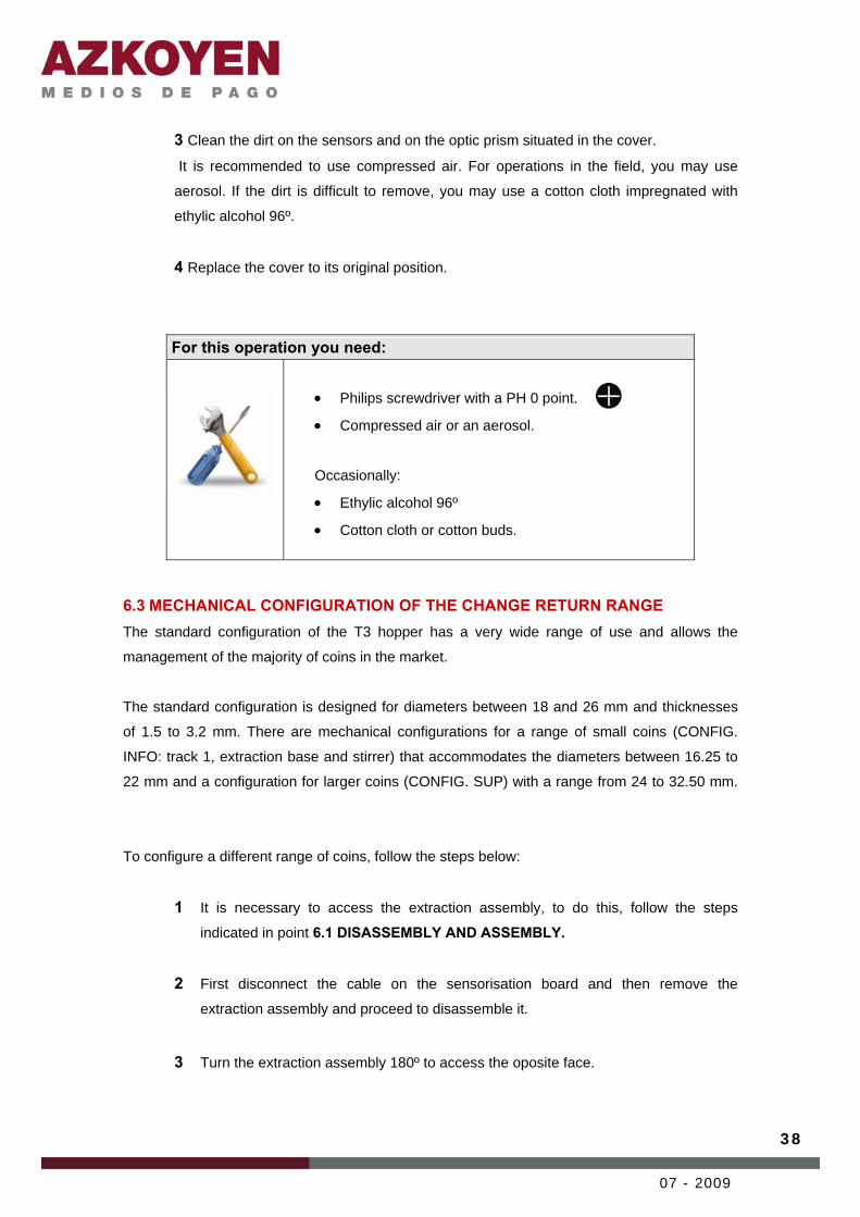
3 Clean the dirt on the sensors and on the optic prism situated in the cover.
It is recommended to use compressed air. For operations in the field, you may use
aerosol. If the dirt is difficult to remove, you may use a cotton cloth impregnated with
ethylic alcohol 96º.
4 Replace the cover to its original position.
6.3 MECHANICAL CONFIGURATION OF THE CHANGE RETURN RANGE The standard configuration of the T3 hopper has a very wide range of use and allows the
management of the majority of coins in the market.
The standard configuration is designed for diameters between 18 and 26 mm and thicknesses
of 1.5 to 3.2 mm. There are mechanical configurations for a range of small coins (CONFIG.
INFO: track 1, extraction base and stirrer) that accommodates the diameters between 16.25 to
22 mm and a configuration for larger coins (CONFIG. SUP) with a range from 24 to 32.50 mm.
To configure a different range of coins, follow the steps below:
1 It is necessary to access the extraction assembly, to do this, follow the steps
indicated in point 6.1 DISASSEMBLY AND ASSEMBLY.
2 First disconnect the cable on the sensorisation board and then remove the
extraction assembly and proceed to disassemble it.
3 Turn the extraction assembly 180º to access the oposite face.
For this operation you need:
• Philips screwdriver with a PH 0 point. • Compressed air or an aerosol.
Occasionally:
• Ethylic alcohol 96º • Cotton cloth or cotton buds.

39
07 - 2009
4 Release the two plastic clips that fix the coin concentrator and pull it out.
2
3
4
5
40
07 - 2009
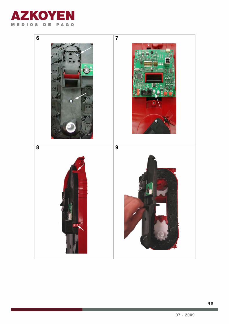
6
7
8
9
41
07 - 2009
10
11
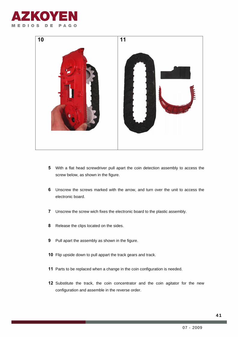
5 With a flat head screwdriver pull apart the coin detection assembly to access the
screw below, as shown in the figure. 6 Unscrew the screws marked with the arrow, and turn over the unit to access the
electronic board. 7 Unscrew the screw wich fixes the electronic board to the plastic assembly.
8 Release the clips located on the sides. 9 Pull apart the assembly as shown in the figure.
10 Flip upside down to pull appart the track gears and track.
11 Parts to be replaced when a change in the coin configuration is needed.
12 Substitute the track, the coin concentrator and the coin agitator for the new
configuration and assemble in the reverse order.

42
07 - 2009
6.4 ADJUSTING THE MAXIMUM AND MINIMUM LEVELS IN THE HOPPER To fit the optic sensors in the positions desired, we recommend following these instructions:
1 Select the location for the minimum and maximum sensor with respect to your
needs. For information on capacity, see the data shown in point 3.4.3 Coin level detection.
2 Pull gently on each optic sensor to remove them from their present position.
3 Insert the pairs of optic sensors in the empty and full positions, making sure they
are horizontally level. Press lightly the sensors to fit them in their holes.
4 The excess cable must be stored using the plastic clips found on the hopper or by
introducing the loop of extra cable into the cavities found in the hopper on its
underside.
For this operation you need:
• A flat screwdriver with a 3 to 5 mm point • The mechanical parts necessary for the
configuration chosen: − Track − Coin concentrator − Flap.

43
07 - 2009
7 TOOLS
The T3 hopper has a micro-controller with flash memory that allows software updating of the
hopper using Azkoyen tools.
7.1 PROGRAMMING TOOLS. 7.1.1 HEUS user application The HEUS application is used to manage programming files, carry out software update
operations, load data bases in validators, configure validators and coin changers, etc.
Figure 22: Main screen of the HEUS application
To find files for the programming tool, enter the technical web of Azkoyen (sat.azkoyen.com)
and search by product and family groups.
Once you have saved these files in the directory \HEUS\DATAFILES you may transfer these
to the T3 hopper directly, using the connection cable and interface or using the TL20.
There is a specific manual for the TL20 and the HEUS, available in the Azkoyen web, you
should consult it for the instructions of these devices.
7.1.2 TL20 Tool For operations in the field, the TL20 tool serves as an intermediary device for the storage of
files. The TL20 works in combination with the user application HEUS from which the

44
07 - 2009
programming files are loaded to this portable device.
Figure 23: TL20 tool 7.2 AZKOYEN SIMULATION TOOLS Azkoyen has developed different applications and interfaces for the simulation and control of
the T3 hopper. The software application used to simulate the master is the Cctalk Manager.
This software it is prepared to manage Cctalk devices, nevertheless, there is a function to
control the parallel hopper.
7.2.1 Cctalk Manager With this application you can manage communications in Cctalk protocol, simulate the available
Cctalk commands, modify their parameters and read the answers of the devices. It is possible to
execute predefined processes such as validators where the application internally manages the
Cctalk commands and shows the control to the user, you may create and execute sequences of
commands to carry out complex or repetitive operations.
For the parallel T3 hopper, there is a simple function that allows you to manage this type of
hopper.

45
07 - 2009
Figure 24: Main screen on the Cctalk Manager application
There are different interfaces that may be used in combination with the Cctalk Manager. Below
are details of the main devices:
7.2.1.1 USB Interface – Cctalk. This interface is connected to the USB port of the PC and provides a Cctalk bus to the exterior.
This connection may be connected to any Cctalk device that has a ribbon cable connector 2 x
5-way. This interface eliminates the echo of the communication Cctalk.
Figure 25: USB interface - Cctalk

46
07 - 2009
It is necessary to connect a power supply of 12/24VdC to supply voltage to the bus to install the
drivers that come with to the unit so that it is recognised by the operating system. 7.2.1.2 Interface RS232 – Cctalk. This interface generates a Cctalk bus on the serial port of the PC (COM port). This interface
does not have the electronics required to the eliminate the echo of the bus, so it receives the
commands that it sends.
Figure 26: RS232 interface - Cctalk It is necessary power the unit with a power supply of 12 or 24VDC depending on the voltage the
elements of the bus need. 7.2.1.3 IS21 Cctalk Interface The IS21 Cctalk interface can work autonomously as an interface of the application Cctalk
Manager. To manage the T3 hopper a RS232 – Cctalk interface is used in combination with the
application Cctalk Manager
Figure 27: IS21 Cctalk interface
The IS21 Cctalk interface makes a Cctalk bus using a serial port (COM) on the PC. The

47
07 - 2009
connection is with a ribbon cable - 2x5 way. The use of this interface does not require the
installation of additional drivers, because the application Cctalk Manager recognises the
connection.

48
07 - 2009
8 NORMS. CE MARK.
The same as all the Azkoyen products, the T3 Hopper complies with the CE marking
regulations.
1. Electromagnetic emission: EN 50081-2 (1992), industrial emission.
• EN 55011 (1991) Continuous conduced emission.
• EN 55011 (1991) Radiated emission.
2. Electromagnetic immunity: EN 50082-2 (1995)
• EN 61000-4-2. ESD
• ENV 50140 (1993) and ENV 50204 (1995). EM and RF radiated.
• EN 61000-4-4 (1995).
• ENV 50141 (1993). RF in common mode.
• EN 61000-4-8 (1993). Magnetic field at 50 HZ.
3. Safety: (EN 60335-1)
4. Plastic parts are of the type H.B.
5. All materials are Rohs compliant.


