TO 1-1-700 TECHNICAL MANUAL CORROSION PREVENTION AND CONTROL FOR GROUND COMMUNICATION, ELECTRONICS AND METEOROLOGICAL (C-E-M) EQUIPMENT AND ITS PROTECTIVE SHELTERS, VANS, AND RADOMES DISTRIBUTION STATEMENT A - Approved for public release; distribution is unlimited. PA Case Number 06-11098. Submit recommended changes or problems with this Technical Order to 406 SCMS/GUEE, Robins AFB, GA 31098. Questions concerning technical content shall be referred to AFLCMC/EZPT-CPCO. Published Under Authority of the Secretary of the Air Force 31 JANUARY 2017 CHANGE 1 - 9 JUNE 2018 BASIC AND ALL UPDATES HAVE BEEN MERGED TO MAKE THIS A COMPLETE PUBLICATION.
Transcript
TO 1-1-700TECHNICAL MANUAL
CORROSION PREVENTION AND CONTROLFOR GROUND COMMUNICATION,
ELECTRONICS AND METEOROLOGICAL(C-E-M) EQUIPMENT AND ITS PROTECTIVE
SHELTERS, VANS, AND RADOMES
DISTRIBUTION STATEMENT A - Approved for public release; distribution is unlimited. PA Case Number 06-11098. Submit recommendedchanges or problems with this Technical Order to 406 SCMS/GUEE, Robins AFB, GA 31098. Questions concerning technical content shall bereferred to AFLCMC/EZPT-CPCO.
Published Under Authority of the Secretary of the Air Force
31 JANUARY 2017 CHANGE 1 - 9 JUNE 2018
BASIC AND ALL UPDATES HAVE BEEN MERGED TO MAKE THIS A COMPLETE PUBLICATION.
Dates of issue for original and changed pages are:
LIST OF EFFECTIVE PAGESINSERT LATEST CHANGED PAGES. DESTROY SUPERSEDED PAGES.
NOTE The portion of the text affected by the changes is indicated by a vertical line in the outer margins ofthe page. Changes to illustrations are indicated by shaded or screened areas, or by miniaturepointing hands.
The purpose of this manual is to provide information on materials and procedures for the prevention and control and repairof corrosion damage to ground electronics equipment and associated structures, shelters, vans, and containers. Supervisoryand maintenance personnel shall use this manual as an instruction for all corrosion control and maintenance efforts. Con-tractors who maintain and repair corrosion on ground electronics equipment and associated structures, shelters, vans, andcontainers shall also use this manual.
1.1 Usage. Use this manual in conjunction with and in support of the system specific ground electronics equipment and/orassociated structure, shelter, van, or container technical orders (TO) as well as general series TO 1-1-8, TO 1-1-689, and TO1-1-691. In case of a conflict between this manual and a system specific ground electronics equipment and/or associatedstructure, shelter, van, or container manual, the system specific manual shall take precedence over this manual. Paragraph 5of this foreword lists related technical publications used by personnel involved in cleaning, corrosion prevention and control,and painting operations.
2 SCOPE.
The material in this manual provides basic cleaning, corrosion prevention and control, and corrective maintenance informa-tion for use by organizational, intermediate, and depot levels of maintenance. This manual consists of a foreword, a safetysummary, and twelve chapters.
Chapter 1 IntroductionChapter 2 General RequirementsChapter 3 Corrosion TheoryChapter 4 Composite and Non-Metallic Material Degradation and RepairChapter 5 Packaging (Storage and Shipping)Chapter 6 Moisture and Fungus ProofingChapter 7 Preventative Maintenance and Refinishing on Structural ComponentsChapter 8 Preventative Maintenance on Electronic ComponentsChapter 9 InspectionChapter 10 Corrosion Prone AreasChapter 11 Corrosion RemovalChapter 12 Sealants
3 SYMBOLS.
- A dash (-) before an index number denotes a part which is not illustrated.* An asterisk (*) flush right of the part number denotes a marking that is to be requisitioned in accor-
dance with DODI 5330.03_AFI 33-395.# A number sign (#) flush right of a part number indicates that detail parts are listed in a separate manual.F The letter “F” before the figure number means “follows” and is used when an assembly or part has not
been assigned an index number, and the figure and index number of the preceding part has been used.
4 ABBREVIATIONS.
All abbreviations used in this manual are shown in the list of abbreviations below. Standard abbreviations are in accordancewith ASME Y14.38, Abbreviations and Acronyms for Use on Drawings and Related Documents.
°C Degrees Celsius°F Degrees Fahrenheit
TO 1-1-700
xv
AFCPCO Air Force Corrosion Prevention and Con-trol Office
AISI American Iron and Steel InstituteALC Air Logistic CenterCC Cubic centimetersC-E-M Communications, Electronics, and Meteo-
rological EquipmentCID Commercial Item DescriptionCLP Cleaner/Lubricant/PreservativeCPC Corrosion Preventive CompoundsCRES Corrosion Resistant SteelsDFT Dry Film ThicknessDLA Defense Logistics AgencyEMI Electromagnetic InterferenceEPTFE Expanded PolytetrafluoroethyleneESD Electrostatic DischargeESDS Electrostatic Discharge SensitivityFIP Form-In-Placegal. GallonHAP Hazardous Air PollutantsHAZCOM DoD Hazard CommunicationHCI Hardness Critical ItemsHg MercurykHz KilohertzKSI Kilograms per Square Inchlb PoundLOX Liquid OxygenmL Millilitermm MillimeterMEK Methyl Ethyl KetoneMSDS Material Safety Data SheetNATO North Atlantic Treaty OrganizationNDI Non-Destructive InspectionNSN National Stock NumberODC Ozone Depleting CompoundsODS Ozone Depleting SubstancesOSHA Occupational Safety and Health Adminis-
trationoz. ouncesPCB Printed Circuit BoardPkg. PackagePMF Pre-Mixed and FrozenPPE Personal Protective EquipmentPSI Pound-force per square inchPSIG Pound-force per square inch, gaugept. PointQPL Qualified Products ListRF Radio FrequencyRH Relative HumidityRPM Revolution per minuteRTV Room Temperature VulcanizingSDS Safety Data Sheet
TO 1-1-700
xvi
SE Support EquipmentSPD System Program DirectorSPI Special Packaging InstructionSPM System Program ManagerTCTO Time Compliance Technical OrderTNP Touch-N-PrepTO Technical OrderTOMA Technical Order Management AgencyUV UltravioletV VoltVCI Volatile Corrosion InhibitorsVLSI Very Large Scale IntegrationWRM War Reserve Material
5 RELATED PUBLICATIONS.
NOTE
When searching TO numbers in the Enhanced Technical Information Management System (ETIMS) catalog,please use the wildcard (*) after typing in the TO number. Many TOs are not available in paper format, (i.e.,digital (WA-1) or Compact Disk (CD-1)). This ensures TOs in all media formats will populate the search.
The following publications contain information in support of this technical manual.
List of Related Publications
Number TitleAFI 20-114 Air and Space Equipment Structural MaintenanceAFI 91-203 Air Force Consolidated Occupational Safety InstructionAFPAM(I) 24-237 Packaging of Material - PreservationASME Y14.38 Abbreviations and Acronyms for Use on Drawings and Related DocumentsDODI 5330.03_AFI 33-395 Defense Logistics Agency (DLA) Document ServicesMIL-DTL-14072 Finishes for Ground-Based Electronic EquipmentMIL-HDBK-263 Electrostatic Discharge Control Handbook for Protection of Electrical and Electronic
Parts, Assemblies and Equipment (Excluding Electrically Initiated Explosive De-vices) (Metric)
MIL-HDBK-304 Package Cushioning DesignMIL-HDBK-454 General Guidelines for Electronic EquipmentMIL-HDBK-773 Electrostatic Discharge Protective PackagingMIL-STD-129 Military Markings for Shipment and StorageMIL-STD-1686 Electrostatic Discharge Control Handbook for Protection of Electrical and Electronic
Parts, Assemblies and Equipment (Excluding Electrically Initiated Explosive De-vices)
MIL-STD-8651 Installation of Identification and Modification of Plates (for Aircraft)MIL-STD-2073-1 DoD Standard Practice for Military PackagingTO 00-5-1 AF Technical Order SystemTO 00-25-108 Communications-Electronics (C-E) Depot SupportTO 00-25-195 AF Technical Order System Source, Maintenance, and Recoverability Coding of Air
Force Weapons, Systems, and EquipmentsTO 00-25-234 General Shop Practice Requirements for the Repair, Maintenance, and Test of Electri-
cal EquipmentTO 1-1-8 Application and Removal of Organic Coatings, Aerospace and Non-Aerospace Equip-
mentTO 1-1-689-3 Cleaning and Corrosion Control - Avionics and Electronics (Vol III)
TO 1-1-700
xvii
List of Related Publications - Continued
Number TitleTO 1-1-689-5 Cleaning and Corrosion Control Consumable Materials and Equipment for Avionics
(Vol V)TO 1-1-690 General Advanced Composite Repair Processes ManualTO 1-1-691 Cleaning and Corrosion Prevention and Control, Aerospace and Non-Aerospace
EquipmentTO 1-1A-8 Engineering Manual Series for Aircraft and Missiles Repair - Structural HardwareTO 1-1A-12 Fabrication, Maintenance, and Repair of Transparent PlasticsTO 1-1A-14 Installation Practices for Aircraft Electric and Electronic WiringTO 31-1-69 Maintenance and Reconditioning of Radomes for Ground Communications-Electronic
EquipmentTO 31-1-75 Maintenance Engineering Standard, General Maintenance PracticesTO 31-1-233 Field Instructions for Painting and Preserving Communications-Electronics EquipmentTO 32-1-101 Use and Care of Hand Tools and Measuring ToolsTO 33B-1-1 Non-destructive Inspection Methods, Basic TheoryTO 35-1-3 Corrosion Prevention and Control, Cleaning, Painting, and Marking of USAF Support
Equipment (SE)TO 35E4-1-162 Field and Depot Maintenance Repair Instruction - Tactical Shelters Foam-Beam-Hon-
eycombTO 35E4-192-2 Maintenance Instructions (Organizational and Intermediate Levels) Ground Support
Equipment Cleaning and Corrosion Control AN/MSM-107TO 42C2-1-7 Process Instruction - Metal Treatment of Electrode Position of Metals and Metal Sur-
face Treatments to Meet AF Maintenance Requirements
6 RECORD OF APPLICABLE TIME COMPLIANCE TECHNICAL ORDERS (TCTOS).
List of Time Compliance Technical Orders
TCTONumber
TCTOTitle
TCTODate
None
7 HARDNESS CRITICAL ITEMS (HCI).
The HCI symbol ( ) establishes special requirements limiting changes and substitutions and that the specificparts listed must be used to ensure hardness is not degraded.
If included, items with nuclear survivability requirements are marked with the HCI symbol ( ). All changes to, orproposed substitutions of, HCIs must be approved by the acquiring activity.
8 ELECTROSTATIC DISCHARGE SENSITIVE (ESDS) ITEMS.
All ESDS parts shall be handled in accordance with the ESDS device handling procedures in TO 00-25-234.
If included, items containing ESDS parts are marked with the ESDS symbol ( ).
TO 1-1-700
xviii
9 CHANGE RECOMMENDATIONS.
Recommendations proposing changes to this technical order shall be submitted on an Air Force Technical Order (AFTO)Form 22 in accordance with TO 00-5-1. Forward completed AFTO Form 22 to the Technical Order Management Agency(TOMA) at: [email protected].
TO 1-1-700
xix/(xx blank)
SAFETY SUMMARY
1 GENERAL SAFETY INSTRUCTIONS.
This manual describes physical and/or chemical processes which may cause injury or death to personnel, or damage toequipment, if not properly followed. This safety summary includes general safety precautions and instructions that must beunderstood and applied during operation and maintenance to ensure personnel safety and protection of equipment. Prior toperforming any specific task, the WARNINGs, CAUTIONs, and NOTEs included in that task shall be reviewed and under-stood.
2 WARNINGS, CAUTIONS, AND NOTES.
WARNINGs and CAUTIONs are used in this manual to highlight operating or maintenance procedures, practices, condi-tions, or statements which are considered essential to protection of personnel (WARNING) or equipment (CAUTION).WARNINGs and CAUTIONs immediately precede the step or procedure to which they apply. WARNINGs and CAUTIONsconsist of four parts: heading (WARNING, CAUTION, or icon), a statement of the hazard, minimum precautions, andpossible results if disregarded. NOTEs are used in this manual to highlight operating or maintenance procedures, practices,conditions, or statements which are not essential to protection of personnel or equipment. NOTEs may precede or follow thestep or procedure, depending upon the information to be highlighted. The headings used and their definitions are as follows:
Highlights an essential operating or maintenance procedure, practice, condition, statement, etc., which if notstrictly observed, could result in injury to, or death of, personnel or long term health hazards.
Highlights an essential operating or maintenance procedure, practice, condition, statement, etc., which if notstrictly observed, could result in damage to, or destruction of, equipment or loss of mission effectiveness.
NOTE
Highlights an essential operating or maintenance procedure, condition, or statement.
3 HAZARDOUS MATERIALS WARNINGS.
Hazardous Materials Warnings are provided through use of the following Hazard Symbols. Consult the HAZARDOUSMATERIALS DESCRIPTION or Safety Data Sheet (SDS) (formerly MSDS) (Occupational Safety and Health Administra-tion (OSHA) Form 20 or equivalent) for specific information on hazards, effects, and protective equipment requirements.MSDS and SDS may be used interchangeably throughout this TO. If you do not have an SDS for the material involved,contact your supervisor, or the base Safety or Bioenvironmental Engineering Offices.
3.1 Hazardous Materials Icons. The following icons are used throughout this Air Force technical manual to indicate theuse of hazardous materials:
The symbol of drops of liquid onto a hand shows that the material will causeburns or irritation of skin and tissue.
TO 1-1-700
xxi
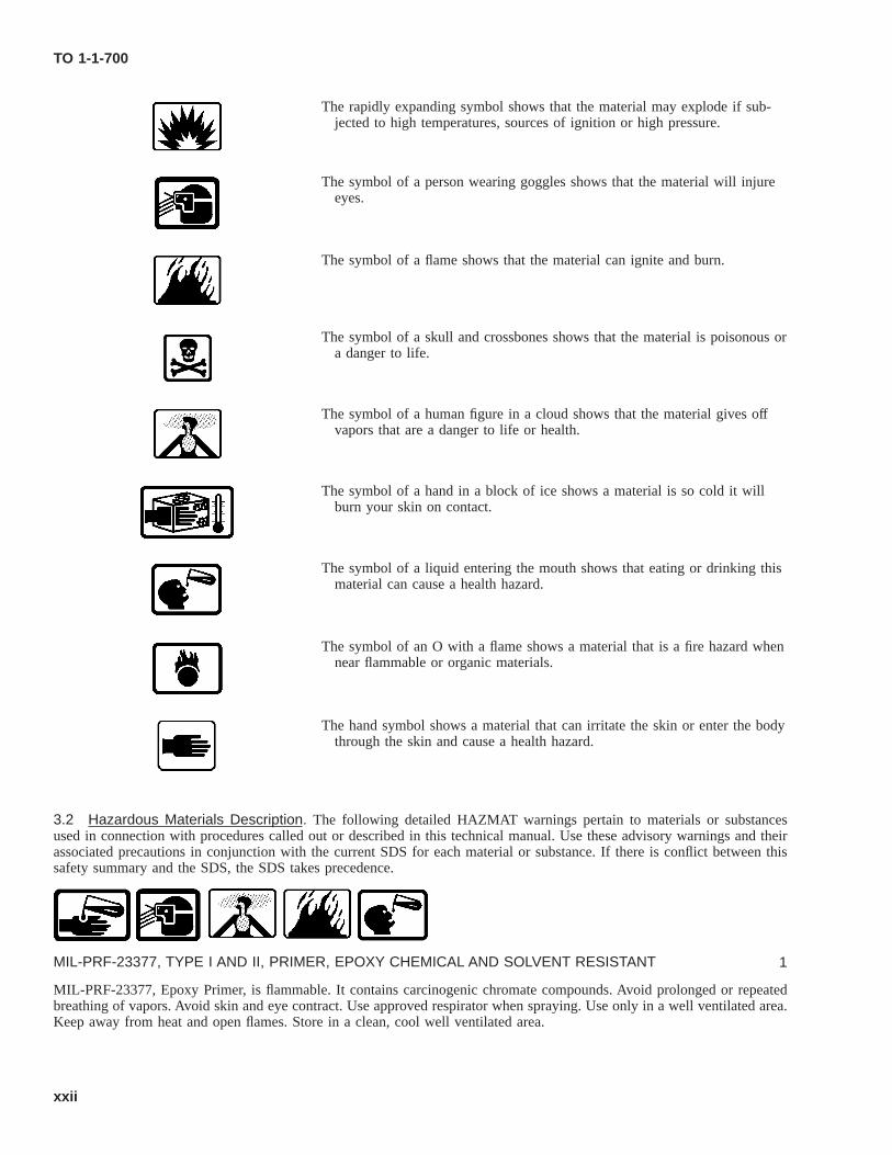
The rapidly expanding symbol shows that the material may explode if sub-jected to high temperatures, sources of ignition or high pressure.
The symbol of a person wearing goggles shows that the material will injureeyes.
The symbol of a flame shows that the material can ignite and burn.
The symbol of a skull and crossbones shows that the material is poisonous ora danger to life.
The symbol of a human figure in a cloud shows that the material gives offvapors that are a danger to life or health.
The symbol of a hand in a block of ice shows a material is so cold it willburn your skin on contact.
The symbol of a liquid entering the mouth shows that eating or drinking thismaterial can cause a health hazard.
The symbol of an O with a flame shows a material that is a fire hazard whennear flammable or organic materials.
The hand symbol shows a material that can irritate the skin or enter the bodythrough the skin and cause a health hazard.
3.2 Hazardous Materials Description. The following detailed HAZMAT warnings pertain to materials or substancesused in connection with procedures called out or described in this technical manual. Use these advisory warnings and theirassociated precautions in conjunction with the current SDS for each material or substance. If there is conflict between thissafety summary and the SDS, the SDS takes precedence.
MIL-PRF-23377, TYPE I AND II, PRIMER, EPOXY CHEMICAL AND SOLVENT RESISTANT 1
MIL-PRF-23377, Epoxy Primer, is flammable. It contains carcinogenic chromate compounds. Avoid prolonged or repeatedbreathing of vapors. Avoid skin and eye contract. Use approved respirator when spraying. Use only in a well ventilated area.Keep away from heat and open flames. Store in a clean, cool well ventilated area.
TO 1-1-700
xxii
MIL-PRF-32295, TYPE II CLEANER, NON-AQUEOUS, LOW-VOC, HAP-FREE 2
MIL-PRF-32295, May cause slight irritation to respiratory passages. High vapor concentrations may cause drowsiness.Direct contact with eyes will cause mild irritation. Repeated or prolonged contact can result in defatting and drying of theskin that may result in dermatitis. Wash hands after use. Well ventilated area or use an approved respirator. Avoid contactwith strong oxidizing agents. Material is combustible. Under no circumstance can it be used around open or potentialignition sources. Rags must be handled as combustible and deposited into properly marked rag containers.
MIL-PRF-680 AND A-A-59601, SOLVENT, DEGREASING, TYPE II AND III 3
MIL-PRF-680 and A-A-59601, Degreasing Solvent, is flammable and an eye, skin, and respiratory tract irritant. Use only ina well ventilated area. Use explosion proof equipment. Nitrile gloves, splash proof goggles and impervious clothing isrequired. Wash thoroughly after handling and before eating or smoking. Keep away from heat and open flames. Store in aclean, cool well ventilated area away from ignition sources and oxidizing agents.
MIL-PRF-87937, CLEANING COMPOUND, AIRCRAFT 4
MIL-PRF-87937, Aircraft Cleaning Compound, is a skin, eye and respiratory tract irritant. Avoid breathing vapors. Avoidskin and eye contact. Rubber or latex gloves and safety glasses with side shields or goggles are required. Wash thoroughlyafter handling. Use only in well ventilated areas.
TT-N-95, NAPHTHA, ALIPHATIC 5
Aliphatic Naphtha, TT-N-95, Aliphatic naphtha is flammable and an eye, skin and respiratory irritant. May be harmful ifswallowed. Use in well ventilated areas. Appropriate skin and eye protection must be worn. Do not ingest. Keep containertightly closed when not in use. Store in a cool, dry, ventilated area, away from incompatible substances.
IPC J-STD-006, SOLDER 6
IPC J-STD-006, Solder, is toxic and a skin, eye and respiratory irritant. Harmful if swallowed. Danger of serious damage tohealth by prolonged exposure through inhalation. Avoid contact with eyes, skin and clothing. Do not ingest. Use only in wellvented areas. Appropriate skin and eye protection must be worn. Respirator not required if ventilation is sufficient to removesmoke from soldering process. Wash thoroughly after contact, before eating, and at the end of the work period.
TO 1-1-700
xxiii
TT-I-735, ALCOHOL, ISOPROPYL 7
Isopropyl Alcohol, TT-I-735, Isopropyl Alcohol is flammable, and an eye, skin and respiratory irritant. It may be harmful ifswallowed. Avoid contact with skin and eyes, and avoid breathing vapors. Do not ingest. Keep away from heat, sparks andflame. Appropriate skin and eye protection must be worn. Use in a well ventilated area. Half mask respirator required inpoorly ventilated areas.
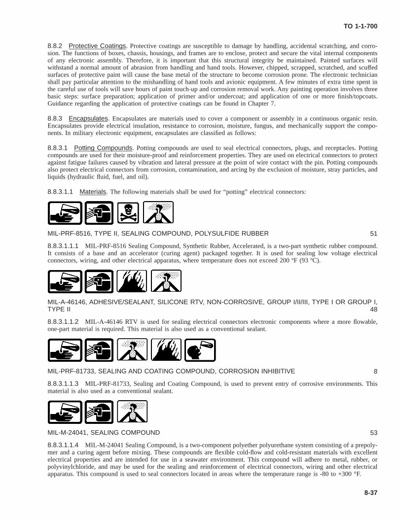
MIL-PRF-81733, SEALING AND COATING COMPOUND, CORROSION INHIBITIVE 8
MIL-PRF-81733, Sealing and Coating Compound, is flammable and may contain chromate compounds that are carcinogens.Avoid skin and eye contact. Solvent resistant gloves and safety glasses are required. Avoid breathing vapors. Use only inwell ventilated areas. Wash thoroughly after handling and before smoking or eating. Keep away from heat and open flames.Store in a clean, cool well ventilated area.
MIL-L-87177, LUBRICANT, CORROSION PREVENTIVE COMPOUND, WATER DISPLACING 9
MIL-L-87177, Corrosion Preventive Compound Lubricant, is a skin, eye and respiratory tract irritant. Wear gloves andsafety goggles. Use only in a well ventilated area. Wash with soap and water after handling product and before eating,drinking or smoking. Keep away from heat and open flames. Store in a clean, cool well ventilated area.
MIL-PRF-81309, Corrosion Preventive Compound, is toxic, flammable and a skin, eye and respiratory tract irritant. Rubbergloves and safety goggles are required. Avoid skin and eye contact. Avoid breathing vapors. Use in well ventilated area.Keep away from heat, sparks, and flame. Vapor accumulations may explode if ignited.
MIL-P-53030, PRIMER, EPOXY, WATER REDUCIBLE, LEAD, CHROME FREE 11
MIL-P-53030, Epoxy Water Reducible Primer, is toxic, flammable and a skin, eye and respiratory tract irritant. Avoidprolonged breathing of vapors or mists. Avoid skin and eye contact. Do not take internally. Approved respirator, protectivegloves, and splash proof goggles are required. Wash hand thoroughly after each use. Keep away from heat, sparks or flame.Avoid strong acids and oxidizing agents.
MIL-PRF-85285, COATING, POLYURETHANE, HIGH SOLIDS 12
MIL-PRF-85285, High Solids Polyurethane Coating, is toxic and flammable. Avoid skin and eye contact. Avoid breathingvapors. Use approved respirator when mixing or spraying. Wear rubber gloves and safety goggles with shield. Do not takeinternally. Wash hands thoroughly after each use. Keep away from heat, sparks and flame. Do not apply to hot surfaces.Store in a well ventilated area.
TO 1-1-700
xxiv
MIL-PRF-85570, CLEANING COMPOUND, AIRCRAFT 13
MIL-PRF-85570, Aircraft Cleaning Compound, is a skin and eye irritant. Avoid skin and eye contact. Use in well ventilatedareas. Rubber gloves and splash proof goggles are required. Wash hands thoroughly after each use. Avoid breathing vapors.Store in cool, dry, well ventilated and low fire risk area. Avoid contact with strong acids or oxidizing agents.
MIL-I-22110, Crystalline Powder, is poison and may be explosive. It is an eye, skin, and respiratory tract irritant. Do nottake internally. Do not inhale dust. Impervious gloves, apron and dust proof goggles are required. Use only in a wellventilated area. Store in a clean, cool well ventilated area away from ignition sources and oxidizing agents.
ASTM D 329 (PART NUMBER O-A-51), ACETONE 15
ASTM D 329 (Part Number O-A-51), Acetone, is a flammable low order oral toxin and is a skin, eye and respiratory tractirritant. Do not take internally. Use only in a well ventilated area. Rubber, vinyl or other imperious gloves and splash proofgoggles are required. Keep away from heat and open flames. Store in a clean, cool well ventilated area.
O-L-164, DRESSING, LEATHER 16
O-L-164, Leather Dressing, is a skin, eye and respiratory tract irritant. Do not take internally. Use only in a well ventilatedarea. Chemical resistant gloves, splash proof goggles and impervious clothing are required. Store in a clean, cool wellventilated area away from ignition sources. Avoid contact with strong oxidizing agents.
A-A-59282/A-A-53880, ALCOHOL, DENATURED ETHYL 17
A-A-59282/A-A-53880, Denatured Ethyl Alcohol, is a flammable liquid and a skin, eye and respiratory tract irritant. Do nottake internally. Use only in a well ventilated area. Chemical resistant gloves, splash proof goggles, chemical resistant bootsand protective clothing should be worn. Store in a clean, cool well ventilated area away from ignition sources.
DIHYDROXYDICHLORODIPHENYL METHANE 18
Dihydroxydichlorodiphenyl methane is an eye, skin, and respiratory tract irritant. Not to be swallowed. Moderately toxic.Use only in a well ventilated area. Chemical gloves and splash proof safety goggles are required. Keep away from heat andopen flames. Store in a clean, cool well ventilated area away from ignition sources.
TO 1-1-700
xxv
ASTM D 3955 (MIL-V-173), VANISH, ELECTRICAL INSULATING 19
ASTM D 3955 (MIL-V-173), Electrical Insulating Vanish, is a skin, eye and respiratory tract irritant. Do not take internally.Rubber gloves, safety goggles, coverall or long sleeves are required. Wash hands with soap and water after handling. Useonly in a well ventilated area. Keep away from heat and open flames. Store in a clean, cool well ventilated area.
SALICYLANILIDE 20
Salicylanilide is very hazardous in case of ingestion and is a skin, eye and respiratory tract irritant. Avoid breathing vaporsand/or dust. Splash goggles, gloves, and dust respirator are required. Use only in a well ventilated area. Store away fromextreme heat and away from strong oxidizing agents. Keep away from heat and open flames.
MIL-DTL-81706 (ALODINE), COATING, CHEMICAL CONVERSION 21
MIL-DTL-81706 (Alodine) Chemical Corrosion Coating, contains carcinogenic chromates and is an eye, skin, and respira-tory tract irritant. May be fatal if swallowed. For mist conditions an approved respirator is required. Rubber gloves, rubberboots, chemical resistant apron, coveralls, and face shield or goggles are required. Use only in a well ventilated area. Keepaway from heat, open flames and other chemicals.
MIL-P-85891, GRAIN, ABRASIVE 22
MIL-P-85891, Abrasive Grain, is flammable and an eye, skin, and respiratory tract irritant. May be harmful if ingested. Useonly in a well ventilated area. Approved respirator, rubber gloves, and safety goggles are required. Wash hands thoroughlywith soap and water after each use.
A-A-3007, THINNER, PHENOLFORMALDEDYDE AND MEDIUM OIL AND STYRENATED ALKYD PAINTS ANDVARNISHES 23
A-A-3007, Thinner, is extremely flammable and a skin, eye and respiratory tract irritant. Use only in a well ventilated area.Impervious gloves, chemical goggles and impervious footwear are required. Do not take internally. Avoid contact with skinand eyes. Avoid breathing vapor and/or mist. Isolate from oxidizers, heat, sparks, electric equipment and open flame. Do notapply to hot surfaces without taking special precautions.
MIL-PRF-16173, COMPOUND, CORROSION PREVENTIVE 24
MIL-PRF-16173, Corrosion Preventive Compound, is an eye, skin, and respiratory tract irritant. May be flammable. Protectarms and legs from chemicals. Use only in a well ventilated area. Keep away from heat and open flames. Store in a clean,cool well ventilated area.
TO 1-1-700
xxvi
A-A-59282, ACID, BORIC 25
A-A-59282, Boric Acid, is a skin, eye and respiratory tract irritant. Avoid contact with skin and eyes. Do not breathe dust ortake internally. Dust mask, protective gloves, and splash proof or dust resistant goggles are required. Wash thoroughly afterhandling. Use only in a well ventilated area. Keep away from heat and open flames.
ASTM D 928, SODIUM BICARBONATE 26
ASTM D 928, Sodium Bicarbonate, is an eye irritant. Avoid contact with eyes. Safety glasses/goggles are required. Store ina clean, cool well ventilated area.
A-A-59199, CLEANING COMPOUND, OPTICAL LENS 27
A-A-59199, Optical Lens Cleaning Compound, is flammable and a skin, eye and respiratory tract irritant. Ingestion cancause blindness and death. Use only in a well ventilated area. Neoprene, nitrile or rubber gloves, safety goggles andprotective apron are required. Wash thoroughly after handling and before eating, drinking or smoking. Store in a clean, coolwell ventilated area away from ignition sources.
MIL-PRF-46010, Heat Cured Solid Film Lubricant, is a skin, eye and respiratory tract irritant. Moderately toxic if ingested.Use only in a well ventilated area. Avoid prolonged or repeated breathing of vapors/dust. Safety goggles are required. Washhands after handling and after each use. Keep away from heat and open flames.
MIL-PRF-46147, LUBRICANT, SOLID FILM, AIR CURED 29
MIL-PRF-46147, Air Cured Solid Film Lubricant, is flammable and a skin, eye and respiratory tract irritant. Do not takeinternally. Use only in a well ventilated area. Avoid prolonged or repeated breathing of vapors/dust. Safety goggles arerequired. Wash hands thoroughly after each use. Keep away from heat and open flames.
MIL-L-23398, LUBRICANT, SOLID FILM 30
MIL-L-23398, Solid Film Lubricant, is a skin, eye and respiratory tract irritant. Use only in a well ventilated area. Avoidskin contact. Rubber gloves and face shield/goggles are required. Wash hands after each use. Keep away from heat and openflames.
TO 1-1-700
xxvii
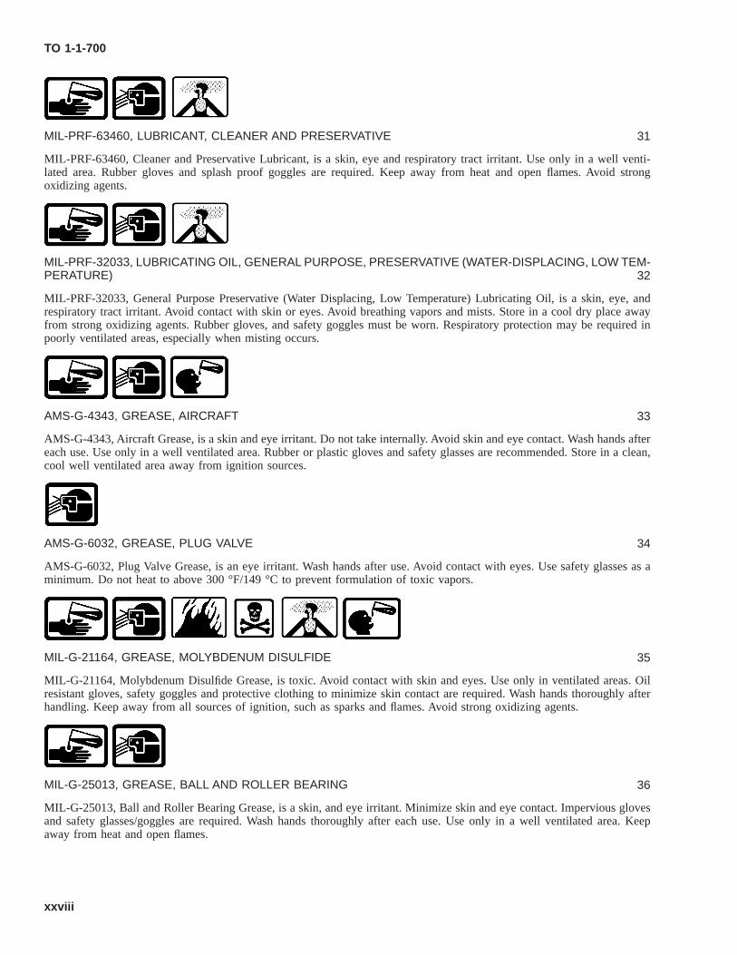
MIL-PRF-63460, LUBRICANT, CLEANER AND PRESERVATIVE 31
MIL-PRF-63460, Cleaner and Preservative Lubricant, is a skin, eye and respiratory tract irritant. Use only in a well venti-lated area. Rubber gloves and splash proof goggles are required. Keep away from heat and open flames. Avoid strongoxidizing agents.
MIL-PRF-32033, LUBRICATING OIL, GENERAL PURPOSE, PRESERVATIVE (WATER-DISPLACING, LOW TEM-PERATURE) 32
MIL-PRF-32033, General Purpose Preservative (Water Displacing, Low Temperature) Lubricating Oil, is a skin, eye, andrespiratory tract irritant. Avoid contact with skin or eyes. Avoid breathing vapors and mists. Store in a cool dry place awayfrom strong oxidizing agents. Rubber gloves, and safety goggles must be worn. Respiratory protection may be required inpoorly ventilated areas, especially when misting occurs.
AMS-G-4343, GREASE, AIRCRAFT 33
AMS-G-4343, Aircraft Grease, is a skin and eye irritant. Do not take internally. Avoid skin and eye contact. Wash hands aftereach use. Use only in a well ventilated area. Rubber or plastic gloves and safety glasses are recommended. Store in a clean,cool well ventilated area away from ignition sources.
AMS-G-6032, GREASE, PLUG VALVE 34
AMS-G-6032, Plug Valve Grease, is an eye irritant. Wash hands after use. Avoid contact with eyes. Use safety glasses as aminimum. Do not heat to above 300 °F/149 °C to prevent formulation of toxic vapors.
MIL-G-21164, GREASE, MOLYBDENUM DISULFIDE 35
MIL-G-21164, Molybdenum Disulfide Grease, is toxic. Avoid contact with skin and eyes. Use only in ventilated areas. Oilresistant gloves, safety goggles and protective clothing to minimize skin contact are required. Wash hands thoroughly afterhandling. Keep away from all sources of ignition, such as sparks and flames. Avoid strong oxidizing agents.
MIL-G-25013, GREASE, BALL AND ROLLER BEARING 36
MIL-G-25013, Ball and Roller Bearing Grease, is a skin, and eye irritant. Minimize skin and eye contact. Impervious glovesand safety glasses/goggles are required. Wash hands thoroughly after each use. Use only in a well ventilated area. Keepaway from heat and open flames.
MIL-G-25537, Oscillating Bearing Grease, is a skin and eye irritant. Minimize skin contact. Rubber gloves and safetyglasses are required. Wash with soap and water after use. Keep away from heat and open flames.
MIL-PRF-27617, GREASE, AIRCRAFT AND INSTRUMENT, FUEL AND OXIDIZER RESISTANT 38
MIL-PRF-27617, Aircraft Grease, is a skin and eye irritant. Rubber gloves and safety goggles are required. Store in a clean,cool well ventilated area away from ignition sources.
MIL-PRF-81322, GREASE, AIRCRAFT GENERAL PURPOSE 39
MIL-PRF-81322, General Purpose Aircraft Grease, is a minor skin and eye irritant. Use only in a well ventilated area. Safetyglasses and gloves are required. Wash hands thoroughly with soap and water after use. Store in a clean, cool well ventilatedarea away from ignition sources.
MIL-DTL-85054, COMPOUND, CORROSION PREVENTIVE 40
MIL-DTL-85054, Corrosion Preventive Compound, is a skin, eye and respiratory tract irritant. Use only in a well ventilatedarea. Avoid breathing vapors. Protective gloves and safety goggles are required. Do not take internally. Wash thoroughlyafter use and before eating, drinking or smoking. Keep away from heat and open flames.
MIL-C-10578, COMPOUND, CORROSION REMOVING AND METAL CONDITIONING 41
MIL-C-10578, Corrosion Removing Compound, is a skin, eye and respiratory tract irritant. Do not get on skin, in eyes or onclothing. Do not breathe vapors or mists. Use only in a well ventilated area. Protective gloves and safety goggles arerequired. Keep away from heat and open flames. Avoid strong alkaline materials. When mixing, always add the phosphoricacid corrosion remover to the water. Do not add the water to the acid, since this causes excessive heat to be generated.
MIL-DTL-53022, PRIMER, EPOXY, CORROSION INHIBITING, LEAD AND CHROMATE FREE 42
MIL-DTL-53022, Epoxy Primer, is flammable and a skin, eye and respiratory tract irritant. Can be fatal if taken internally.Use only in a well ventilated area. Use of an approved respirator is required when spraying primer. Solvent impermeablegloves and safety glasses/goggles are required. Keep away from heat and open flames.
TO 1-1-700
xxix
MIL-DTL-64159, COATING, POLYURETHANE, CHEMICAL RESISTANT, WATERBORNE 43
MIL-DTL-64159, Chemical Resistant Polyurethane Coating, is a skin, eye and respiratory tract irritant. Use only in a wellventilated area. An approved respirator, protective gloves, and safety goggles are required. Wash hands after each use. Keepaway from heat and open flames. Store in a clean, cool well ventilated area.
MIL-PRF-85582, PRIMER, EPOXY, WATERBORNE 44
Water Borne Epoxy Primer, MIL-PRF-85582, Water borne epoxy primer is highly flammable and may contain isocyanateswhich are toxic to the skin, eyes, and respiratory tract. May be harmful if swallowed. Contact with the eyes may causeirritation. Avoid contact with eyes, skin and clothing. Do not ingest. Appropriate skin and eye protection is required and localexhaust ventilation and/or respiratory protection may be required. Do not ingest. Keep away from heat, sparks and flame.Keep container tightly closed when not in use.
MIL-PRF-26915, PRIMER, ZICH RICH, WATERBORNE 45
MIL-PRF-26915, Zinc Rich Waterborne Primer, is flammable and a skin, eye and respiratory tract irritant. Use only in a wellventilated area. Avoid eye and skin contact. Avoid breathing sanding dust. Approved respirator, rubber gloves and safetygoggles are required. Keep away from heat and open flames.
MIL-PRF-3150, LUBRICATING OIL 46
MIL-PRF-3150, Lubricating Oil, is a skin, eye, and respiratory tract irritant. Avoid skin and eye contact. Avoid breathingvapors/mist. Use only in well ventilated area. Rubber gloves and safety goggles are required. Store in cool, dry and wellventilated area.
MIL-DTL-25681, Molybdenum Disulfide Silicone Lubricant, is an eye, skin, and respiratory tract irritant. Avoid breathingvapors, and skin and eye contact. Rubber gloves and safety goggles are required. Wash hands thoroughly after handling. Useonly in well ventilated areas.
MIL-A-46146, ADHESIVE/SEALANT, SILICONE RTV, NON-CORROSIVE, GROUP I/II/III, TYPE I OR GROUP I,TYPE II 48
MIL-A-46146, Non-Corrosive Silicone RTV Adhesive/Sealant, is flammable and a skin and eye irritant. Avoid contact withskin and eyes. Use in well ventilated areas and avoid prolonged breathing of vapors. Safety goggles required. Avoid contactwith oxidizing materials. Store below 90 °F. Wash hands before eating and at end of work shift.
TO 1-1-700
xxx
MIL-D-16791, DETERGENT, NON-IONIC 49
MIL-D-16791, Non-Ionic Detergent, Type I, is an eye irritant. Avoid contact with eyes. Chemical resistant goggles arerequired. Store away from heat sources. Avoid contact with strong oxidizing or reducing agents. Material is corrosive tocopper and brass on long storage.
AMS-S-83318, SEALING COMPOUND, LOW TEMPERATURE CURING 50
AMS-S-83318, Low Temperature Curing Sealing Compound, is a skin, eye and respiratory tract irritant. Avoid repeated orprolonged contact with the skin. Use in well ventilated areas only. Nitrile or rubber gloves and chemical resistant goggles arerequired. To prevent ingestion, always wash your hands before eating or smoking. Store in cool, dry, well ventilated areaaway from heat, ignition sources and direct sunlight.
MIL-PRF-8516, TYPE II, SEALING COMPOUND, POLYSULFIDE RUBBER 51
MIL-PRF-8516, Sealing Compound, Type II, is toxic. Avoid contact with skin and eyes. Avoid breathing vapors. Wash handsthoroughly after each use; do not smoke, eat or drink in work area. Keep away from heat and flames. Rubber gloves, safetygoggles and skin protection required.
HUMISEAL 1A27 52
HumiSeal 1A27 is flammable and an eye, skin and respiratory irritant. Avoid contact with eyes, skin and clothing. Use onlyin well ventilated areas. Appropriate skin and eye protection must be worn. Approved respirator required in areas of poorventilation. Keep away from sources of ignition. Wash thoroughly after handling. Store in clean, cool and well ventilatedareas away from ignition areas.
MIL-M-24041, SEALING COMPOUND 53
MIL-M-24041, Sealing Compound, is a skin, eye and respiratory tract irritant. Avoid skin and eye contact. Avoid breathingvapors/mist. Use only in well ventilated area. Rubber gloves and safety goggles are required. Store in cool, dry and wellventilated area.
SAE AMS-S-8802, SEALING COMPOUND (POLYSULFIDE) 54
SAE AMS-S-8802, Sealing Compound (Polysulfide), is toxic and flammable. Avoid prolonged breathing of vapors andprolonged or repeated skin contact. Keep away from heat, sparks, and open flame. Use with adequate ventilation to preventvapor buildup. Rubber gloves, safety goggles and protective skin compound or coveralls are required.
TO 1-1-700
xxxi
MIL-T-81772, AIRCRAFT COATING THINNER 55
MIL-T-81772, Thinner is a highly flammable liquid and vapor, and can cause serious eye damage. Is a skin, eye, andrespiratory irritant. Is suspected of causing cancer. May damage unborn children. Prolonged or repeated exposure may causeorgan damage. Avoid contact with skin and eyes, and avoid breathing vapors. Do not ingest. Keep away from sources ofignition. Appropriate skin and eye protection must be worn. Use in a well ventilated area.
DOD-P-15328, PRIMER, PRETREATMENT (WASH) FOR METALS 56
DOD-P-15328, Pretreatment (Wash) Primer, is flammable and a skin, eye, and respiratory tract irritant. Avoid breathingvapors. Use only in well ventilated areas. Rubber gloves and safety glasses with side shields are required. Wear face shieldwhen spraying. Avoid excessive heat and sources of ignition.
MIL-C-8514, PRIMER, PRETREATMENT (WASH) FOR METALS 57
MIL-C-8514, Pretreatment (Wash) Primer, is flammable and a skin, eye, and respiratory tract irritant. Avoid breathingvapors. Use only in well ventilated areas. Rubber gloves and safety glasses with side shields are required. Wear face shieldwhen spraying. Do not store above 120 °F. Keep away from heat, sparks and flame.
A-A-59921/MIL-C-43616, CLASS 1A, CLEANING COMPOUND, AIRCRAFT 58
A-A-59921/MIL-C-43616, Class 1A, Aircraft Cleaning Compound, is a skin, eye and vapor irritant. Keep away from eyesand use in ventilated area. Neoprene gloves and chemical goggles are required. Wash hands thoroughly after handling. Storeat temperatures of 30 °F- 90 °F away from sparks/flame/heat.
SAE AMS-1640 (MIL-C-38334), Corrosion Removing Compound, Type I, is moderately toxic to skin, eyes, and respiratorytract. Chemical splash proof goggles and/or face shield and chemical resistant rubber gloves and aprons are required. Avoidinhaling fumes, and use only in a well ventilated area.
SEMCO PASA-JELL 102, CHEMICAL CORROSION REMOVAL FOR ALUMINUM ALLOYS 60
Semco Pasa-Jell 102 is moderately toxic and is a skin, eye, and respiratory tract irritant. Chemical or splash proof gogglesand/or face shield and chemical resistant gloves and apron are required. Good ventilation is normally adequate. Do not usaluminum or any type of steel wool to apply or agitate or fire will result. Wash thoroughly after each use.
TO 1-1-700
xxxii
A-A-55827, CHROMIUM TRIOXIDE 61
A-A-55827, Chromium Trioxide, is highly toxic to the eyes, skin and respiratory tract. Chemical splash proof goggles and/orface shield, chemical resistant rubber gloves and apron are required. Good general ventilation is usually adequate. Do notinhale dust. Reacts vigorously or violently with a range of organic materials.
A-A-59260 (MIL-C-14460, TYPE I), CORROSION REMOVING COMPOUND 62
A-A-59260 (MIL-C-14460, Type I), Corrosion/Rust Removing Compound, is a sodium hydroxide solution and therefore,highly alkaline. It is toxic to skin, eyes and respiratory tract. Chemical splash proof goggles and/or face shields and chemicalresistant rubber gloves and aprons are required. Heated dip tanks shall be properly ventilated, and ventilation shall beevaluated by the Bioenvironmental Engineer prior to their initial use. When preparing/mixing this highly alkaline solution,never pour water onto the sodium hydroxide granules or flakes; this will generate an excessive amount of heat. Always pourthe sodium hydroxide granules/flakes into the water.
SEMCO PASA-JELL 101, CHEMICAL CORROSION REMOVAL FOR STAINLESS STEEL (CRES) AND NICKELBASED ALLOYS 63
Semco Pasa-Jell 101 contains strong acids and is toxic to the skin, eyes and respiratory tract. Chemical splash proof gogglesand/or face shield and chemical resistant rubber gloves and aprons are required. Avoid inhaling fumes and use only in a wellventilated area. Do not use aluminum or steel wool to agitate as a combustible reaction will occur. Wash thoroughly aftereach use.
A-A-59105 (O-N-350), NITRIC ACID 64
A-A-59105 (O-N-350), Nitric Acid, is highly toxic and a strong oxidizer. Do not get on skin, eyes, or clothing. Do notbreathe vapors or mist. Use only in well ventilated areas. Wash hands thoroughly after handling. Never pour water into acid,as excessive heat will be generated. Always pour the acid into the water. Do not store near combustible materials.
MIL-A-24641, ACID, HYDROFLUORIC 65
MIL-A-24641, Hydrofluoric Acid, is highly toxic if inhaled in high concentrations. Ingestion is harmful/fatal. Do not get onskin or in eyes. Do not breathe vapors or mists. Use only in well ventilated area. Rubber gloves, safety goggles with faceshield, impervious boots, apron, and coveralls are required. Observe good personal hygiene practices and do not wearcontaminated clothing or footwear. Never pour water into acid, as excessive heat will be generated. Always pour the acidinto the water.
TO 1-1-700
xxxiii
A-A-55828 (O-S-809), SULFURIC ACID SOLUTIONS 66
A-A-55828 (O-S-809), Sulfuric Acid Solutions, are toxic to the skin, eyes, and respiratory tract. Use only in well ventilatedareas. Chemical, splash proof goggles and/or face shields and chemical resistant rubber gloves and aprons are required.Highly reactive. Prevent accidental contact with water. Never add water to corrosive. Always add corrosives to water. Storein cool, dry, well ventilated location.
MIL-A-46106, Corrosive Silicone RTV Adhesive/Sealant, is flammable and a skin and eye irritant. Avoid contact with skinand eyes. Use in well ventilated areas and avoid prolonged breathing of vapors. Do not take internally. Avoid contact withoxidizing materials. Store below 90 °F. Wash hands before eating and at end of work shift.
PR-1773, Sealing Compound, is a skin, eye and respiratory tract irritant. Use only in well ventilated area. Solvent resistantgloves and safety glasses are required. Wash thoroughly after handling.
SAE AMS 3267, Sealing Compound, is a skin, eye and respiratory tract irritant. Use only in well ventilated area. Avoidbreathing vapor and/or mist. Solvent resistant gloves, and splash proof goggles and faceshield are required. Wash thoroughlyafter handling. Store in cool, dry, well ventilated area.
SAE AMS 3374, SEALANT, SILICONE 70
SAE AMS 3374, Silicone Sealant, is a mild eye and skin irritant. Avoid contact with skin and eyes. Remove contact lensesbefore using sealant. Wash hands after handling.
MIL-S-85420, SEALING COMPOUND, QUICK REPAIR, LOW TEMPERATURE CURING 71
MIL-S-85420, Sealing Compound, is a skin, eye and respiratory tract irritant. Use only in well ventilated area. Imperviousgloves, splash proof goggles and protective clothing are required. Avoid breathing vapor and/or mists. Wash thoroughly afterhandling and before eating, drinking, smoking or using restroom facilities. Store in cool, dry, well ventilated area at atemperature not to exceed +80 °F.
SAE AMS 3255, Polytetrafluoroethylene Sealing Tape, is a skin, eyes and respiratory tract irritant. Keep away from eyes.Use in a well ventilated area. Wash hands thoroughly after handling.
SAE AMS-3277 (MIL-S-29574), SEALING COMPOUND, LOW TEMPERATURE CURING 73
SAE AMS-3277 (MIL-S-29574) Sealing Compound, is flammable and a skin, eye and respiratory tract irritant. Use only inwell ventilated area. Chemical resistant gloves and safety glasses/face shield must be worn. Wear appropriate clothing toavoid prolonged skin contact. Wash hands thoroughly after handling this product and prior to eating, drinking or smoking.Store below 120 °F, in a dry area away from acids, oxidizers, open flame or other possible ignition sources.
SAE AMS 3166, SOLVENT, WIPING 74
SAE AMS 3166, Wiping Solvent, is flammable and toxic to the skin, eyes and respiratory tract. Use only in well ventilatedareas. Approved respirator, impervious gloves, rubber apron, and chemical resistant goggles are required. Store in wellventilated areas away from heat, sparks, electrical equipment and open flames.
A-A-59281, SOLVENT, CLEANING 75
A-A-59281, Cleaning Solvent, is extremely flammable. Closed containers may explode if exposed to extreme heat. Use onlyin well ventilated areas. Approved respirator, impervious gloves, rubber apron, and chemical resistant goggles are required.Isolate from oxidizers, chromates and peroxides. Store in well ventilated areas away from heat, sparks, electrical equipmentand open flames. Vapors may ignite explosively and spread long distances. Prevent vapor buildup.
SAE AMS-3276 (MIL-S-83430), SEALING COMPOUND, INTEGRAL FUEL TANK 76
SAE AMS-3276 (MIL-S-83430), Sealing Compound, is a skin and eye irritant. Solvent resistant gloves and safety gogglesare required. Wash thoroughly after handling and before smoking or eating. Avoid ingestion. Avoid oxidizing agents, heat,sparks or open flames.
TT-P-2760, PRIMER, POLYURETHANE, ELASTOMERIC, HIGH SOLIDS 77
TT-P-2760, High Solids Polyurethane Primer, is flammable and a skin, eye and respiratory tract irritant. Avoid breathingvapor and/or mist. Approved organic vapor respirator, cotton, neoprene, or rubber gloves, and splash proof goggles or faceshield are required. Use of long sleeve and long leg clothing is recommended. Wash thoroughly after handling and beforeeating or smoking. Avoid storing near high temperatures, fire, open flames, and spark sources.
TO 1-1-700
xxxv
VV-P-236, PETROLATUM 78
Petrolatum, VV-P-236, Petrolatum may cause mild skin irritation after prolonged or repeated exposure. Mist may irritate theeyes. Appropriate skin and eye protection must be worn. Wash hands thoroughly after use.
4 SAFETY PRECAUTIONS.
The following safety precautions shall be observed while performing procedures in this manual.
• Dangerous voltages are present at system connectors. Ensure power is OFF prior to connecting or disconnectingcables.
• Do not wear metal frame glasses, rings, watches, or other metal jewelry while working on electronic equipment.
• Some cleaning materials specified herein are flammable and/or toxic. Keep away from open flame or other ignitionsources. Provide adequate ventilation and avoid skin/eye exposure.
• Cleaning with compressed air can create airborne particles that may enter eyes or penetrate skin. Pressure shall notexceed 30 pound-force per square inch, gauge (PSIG). Wear goggles. Do not direct compressed air against skin.
TO 1-1-700
xxxvi
CHAPTER 1INTRODUCTION
1.1 CORROSION CONTROL PROGRAM.
All activities responsible for maintenance of Ground Communications, Electronics, and Meteorological (C-E-M) equipmentand the shelters, vans and support equipment in/on which they are contained/mounted shall establish a corrosion preventionand control program as required by AFI 20-114. The type of program depends upon the environment to which the equipmentmay be exposed such as industrial gases, rain, high humidity, deicing chemicals, mud, and salt-laden air or mists if locatedin the vicinity of salt water. A comprehensive corrosion prevention and control program shall provide ground communica-tions and electronics equipment maintenance work centers with personnel who are both trained in and dedicated to theprevention, early detection, reporting, and repair of corrosion damage. This type of corrosion prevention and control programprevents much of the corrosion from occurring and/or detects it in its initial stages so that early treatment will minimizecostly repairs and improve the operational readiness of ground communications and electronics equipment and the shelters,vans and support equipment in/on which they are contained/mounted.
1.1.1 Training. All personnel performing maintenance on ground communications and electronics equipment and theshelters, vans and support equipment in/on which they are contained/mounted shall be trained in basic corrosion preventionand control skills and must be fully aware of the reasons for the corrosion prevention and control program. Without suchtraining and understanding, more severe damage and additional problems will result.
1.1.2 Maintenance. An effective corrosion prevention and control program shall include thorough cleaning, inspection,preservation, and lubrication at established specified intervals according to Chapter 7 and the applicable system/equipmentspecific maintenance manual. Check for corrosion damage and the integrity of the protective finishes and preservativecoatings during all scheduled and unscheduled maintenance. Early detection and repair limits the severity of the damage.When corrosion is found, treat the corrosion as prescribed in Chapter 7 and Chapter 8, Technical Order (TO) 1-1-689-seriesand TO 1-1-691, and the applicable system/equipment specific maintenance manual using only approved materials, equip-ment, and techniques. Seal according to Chapter 12, TO 1-1-691, and the applicable system/equipment specific maintenancemanual. Touch-up or repaint according to TO 1-1-8 and the applicable system/equipment specific maintenance manual. Allmaintenance personnel shall report corrosion promptly according to established Air Force directives.
1.2 SAFETY.
Safety is everyone’s business and concern.
1.2.1 Responsibility of Supervisors. Work center supervisors shall receive the following training in accordance withestablished Air Force directives:
• The recognition and elimination of hazards.
• Occupational safety and health.
• The safety of the individual.
• Accident investigation and reporting.
• The inspection and maintenance of personal protective equipment (PPE).
1.2.1.1 Supervisors shall ensure that all maintenance personnel are informed of:
• Current safety procedures.
• Characteristics of materials to which they will be exposed and the existence and location of the applicable MaterialSafety Data Sheets (MSDS).
TO 1-1-700
1-1
• Required protective clothing and PPE to ensure safety of personnel.
1.2.1.2 Supervisors shall also ensure that an adequate supply of safety equipment and PPE are available and in a ready-for-issue condition and personnel under their control use the appropriate safety equipment and PPE while exposed tohazardous conditions during corrosion prevention and control operations to prevent accidents, injuries, and occupationalillnesses. Supervisors shall instruct personnel and make sure that they report any protective equipment and PPE that isbroken, damaged, defective, or inadequate to ensure that no one uses equipment that is not in a satisfactory and serviceablecondition.
1.2.1.3 Finally, supervisors shall ensure that all their personnel comply with occupational safety and health requirementsto include: medical examinations, respirator training and fit testing, and protection for eyes, ears, head, skin, and feet.
1.2.2 Materials Handling. Many of the materials and procedures outlined in this manual are either potentially hazardousto personnel or damaging to ground communications and electronics equipment and the shelters, vans and support equipmentin/on which they are contained/mounted; especially when improperly used. When using chemicals such as paint removers,cleaning compounds, conversion coatings, and solvents or mechanical tools such as sanders, grinders, and abrasive blastingequipment, follow the correct procedures, use the appropriate PPE, and use proper protection for surrounding areas on theequipment being repaired to prevent personnel injury and/or functional or structural damage to the equipment. Read theappropriate WARNINGS and CAUTIONS in this manual and the MSDSs prior to using any hazardous materials. Misuse ofsome materials can damage parts and/or generate corrosion which may cause catastrophic failures. Refer to DODI 6050.05,DoD Hazard Communications (HAZCOM) Program, and the appropriate Air Force directives for handling, storage, anddisposal of hazardous materials. Refer to local directives and policies pertaining to hazardous waste management. When indoubt, contact the base safety office and/or the bioenvironmental engineer for assistance.
1.3 MATERIALS.
Consumable materials listed in TO 1-1-689-5 and TO 1-1-691, Appendix A, shall be used for cleaning and corrosionprevention and control. The materials and equipment listed in these appendices have been approved after extensive testing toprove their ability to perform properly and effectively without causing damage to any of the metallic or nonmetallicmaterials used in ground communications and electronics equipment and the shelters, vans and support equipment in/onwhich they are contained/mounted when used according to procedures in these manuals. Only those materials listed in thesemanuals shall be used for cleaning of and corrosion prevention and control on ground communications and electronicsequipment and the shelters, vans and support equipment in/on which they are contained/mounted unless they are specified inand required by procedures in a system specific maintenance manual. When materials and processes considered to be animprovement over existing ones are found, information concerning these materials and processes shall be forwarded to theequipment System Program Manager (SPM) and the Air Force Corrosion Prevention and Control Office (AFCPCO), AFRL/RXSSR, for further evaluation and approval. When several materials and/or methods are listed, the preferred one is listedfirst with alternates following.
Any asset that has been contaminated or potentially contaminated must be identified, marked and decontaminated in accor-dance with AFMAN 10-2503, Operations in a Chemical, Biological, Radiological, Nuclear, and High-Yield Explosive(CBRNE) Environment and TO 00-110A-1.
TO 1-1-700
1-2 Change 1
CHAPTER 2GENERAL REQUIREMENTS
2.1 GENERAL.
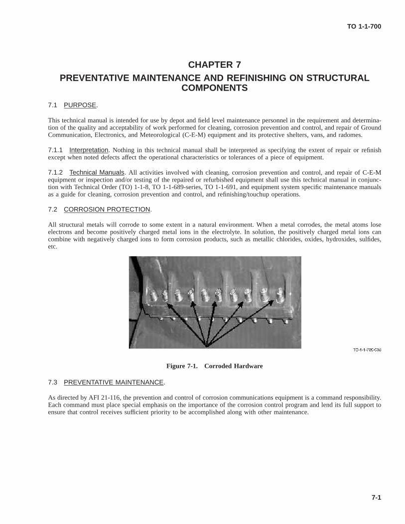
This technical manual is intended for use by depot and field level maintenance personnel in the requirement and determina-tion of the quality and acceptability of work performed for corrosion prevention and control and repair of Ground Commu-nication, Electronics, and Meteorological (C-E-M) Equipment and its protective shelters, vans, and radomes. Nothing in thistechnical manual shall be interpreted as specifying the extent of repair or refinish except when noted defects affect theoperational characteristics or tolerances of a piece of equipment. All activities involved with corrosion prevention andcontrol and repair of C-E-M equipment or inspection and/or testing of the repaired or refurbished equipment shall use thistechnical manual in conjunction with Technical Order (TO) 1-1-8, TO 1-1-689-series, TO 1-1-691, and equipment systemspecific maintenance manuals as a guide for corrosion prevention and control and refinishing/touchup operations.
2.1.1 Specification Numbers.
MIL-PRF-23377, TYPE I AND II, PRIMER, EPOXY CHEMICAL AND SOLVENT RESISTANT 1
The primary specification number only without the revision letter suffix (e.g. MIL-PRF- 23377 and not MIL-PRF-23377,etc.) will be used when military, federal, and/or commercial item description (CID) specifications are listed in this manual toavoid having to update this manual every time a specification is revised. Use of materials conforming to the most currentrevision of a specification is implied by referencing the primary specification number without the revision letter suffix.
2.1.2 Material Substitutions. Manufactured items shall conform to the applicable requirements of MIL-HDBK-454 un-less otherwise covered by Air Force technical data. If a material substitute conforms to this handbook, no further authoriza-tion for its use is required. If a satisfactory substitute conforming to MIL-HDBK-454 cannot be found or if in doubt as to theapplicability of the substitute, forward the problem along with a proposed solution to the equipment System ProgramManager (SPM) at the prime Air Logistics Center (ALC).
2.2 NONSPECIFIC GENERAL REQUIREMENTS.
2.2.1 Workmanship. This list of general nonspecific requirements establishes repair standards that determine the accept-ability of repaired and/or refurbished equipment.
a. Repair and/or rework components/parts in a thoroughly workman-like manner.
b. Maintain dimensions within the specified tolerances in/on the equipment drawings, specifications, or system specifictechnical manuals. If not specified, hold dimensions within tolerances that are according to the best manufacturingpractice for the type of equipment involved.
c. If special tools are required, they shall not be unserviceable, broken, or excessively worn; and mounting facilities forthe tools shall be adequate.
2.2.2 Overall Cleanliness and Cleaning. Maintain the exterior and interior of equipment and components such that theywill be free of grease, dirt, corrosion, fungus, and any other extraneous/foreign matter. Use only those cleaning processesthat have no harmful or damaging effect on the equipment being cleaned. Observe all the warnings, cautions, and notes listedbelow as well as in other published specific cleaning procedures during all cleaning operations.
TO 1-1-700
2-1
MIL-PRF-32295, TYPE II, CLEANER, NON-AQUEOUS, LOW-VOC, HAP-FREE 2
MIL-PRF-680 AND A-A-59601, SOLVENT, DEGREASING, TYPE II AND III 3
MIL-PRF-87937, CLEANING COMPOUND, AIRCRAFT 4
TT-N-95, NAPHTHA, ALIPHATIC 5
MIL-PRF-680, MIL-PRF-32295, Type II and A-A-59601 Dry Cleaning/Degreasing Solvents and TT-N-95 Ali-phatic Naphtha shall not be used on electrical parts, and rubber jacketed cords and cables as these solvents candamage them. Failure to comply could result in damage to, or destruction of, equipment or loss of missioneffectiveness.
a. Clean exterior and interior structural areas of vans, shelters, and equipment cases with MIL-PRF-87937, Type III(undiluted) or Type IV (diluted solution) Cleaning Compounds or MIL-PRF-680, MIL-PRF-32295, Type II or A-A-59601, Type II or III Dry Cleaning/Degreasing Solvents or TT-N-95 Aliphatic Naphtha or other cleaners as dictated bythe cleaning situation, system-specific manuals, or equipment System Program Director (SPD) involved according tomethods and procedures in Chapter 7.
b. Clean electrical contacts per procedures in Chapter 8.
c. Clean electrical parts such as resistors, fixed or variable capacitors, coils, and switches with an appropriate non-metallic, soft bristle brush or a lint-free cloth only per procedures in Chapter 8.
d. Clean ventilation screens and filters with an appropriate vacuum cleaner to remove any accumulated dust or debris thatwould impede the free flow of air.
TO 1-1-700
2-2
Use of compressed air can create airborne particles that can enter the eyes and/or penetrate the skin and causeserious injury. Air pressure for compressed air cleaning shall be maintained at 30 pound-force per square inch,gauge (PSIG) or lower at the nozzle. Use of proper eye and hand protection is mandatory during compressed aircleaning operations. Control of nozzle direction to direct the air stream away from equipment interiors, otherequipment and other personnel in the area is also required.
Compressed air with entrained moisture or oils can cause corrosion of and/or interfere with the electrical proper-ties of equipment. Use only compressed air from a source with an oil/water separator installed and preferably, withan additional air dryer also. To be on the safe side, always direct the first air blast at the floor to clear any possiblecondensed moisture from the compressed air line before using it for cleaning.
e. Compressed air may be used to clean away dirt, dust, and other debris from equipment mounting areas in vans andshelters, the exterior and interior of removed equipment cases and covers, an open equipment chassis. Compressed airshall not be used to clean speaker cones, the interior of electrical meters, plates of tuning capacitors, relay contacts,plates of selenium rectifiers, transistors, and distributor wiring in high or ultra-high frequency Radio Frequency (RF)amplifiers or oscillator circuits. Use a hand bellows or rubber bulb to direct air onto these components for cleaning.
f. Lubricate all components/parts requiring lubrication according to the applicable equipment system specific technicalmanual (Air Force or commercial) and/or lubrication charts after cleaning operations. Parts not usually covered bylubrication requirements such as door mechanisms, hinges, latches, locks, and exposed gears and bearings shall also belubricated at this time with an appropriate water displacing lubricant listed in Chapter 7 to prevent corrosion, squeak-ing, and binding.
2.2.3 Soldering. Soldering can be the source of many corrosion problems in electronics equipment if the process is notproper and/or the wrong materials are used. The process consists of pre-cleaning areas to remove contaminants, tinning ofareas, applying flux or using a flux cored solder, heating to flow the solder, and post cleaning to remove flux residue. Unlessotherwise directed in a system specific technical manual, use only the materials listed in this manual for soldering operations.Solder shall be a non-activated/non-corrosive rosin or rosin/alcohol flux cored solder conforming to ANSI-J-STD-006 andlisted in the most current qualified products list (QPL) for this specification. Use the following techniques to provide good,corrosion free soldered electrical connections in ground C-E-M equipment:
IPC J-STD-006, SOLDER 6
TT-I-735, ALCOHOL, ISOPROPYL 7
TT-N-95, NAPHTHA, ALIPHATIC 5
TO 1-1-700
2-3
• Soldering can generate toxic fumes and sometimes pop solder particles into the air. Avoid breathing the fumes,and provide adequate ventilation. Eye protection is required. Failure to comply could result in injury to, ordeath of, personnel or long term health hazards.
• Use of compressed air can create airborne particles that can enter the eyes and/or penetrate the skin and causeserious injury. Air pressure for compressed air cleaning shall be maintained at 30 PSIG or lower at the nozzle.Use of proper eye and hand protection is mandatory during compressed air cleaning operations. Control ofnozzle direction to direct the air stream away from equipment interiors, other equipment, and other personnel inthe area is also required. Failure to comply could result in injury to, or death of, personnel or long term healthhazards.
Do not use acid or acid salt type fluxes in soldering electrical connections as this can cause corrosion problems atthese connections as well as elsewhere within electronic equipment. Acid or acid salt type fluxes can be used onlyfor tinning and soldering of mechanical joints not associated with electrical connections; and then, only if com-pletely neutralized and removed immediately after the soldering operation.
a. Clean areas to be soldered with a lint-free cloth wet with TT-I-735, Isopropyl Alcohol, or TT-N-95, Aliphatic Naphtha,to remove any contaminants; and wipe the areas dry with a clean, lint-free cloth.
b. Use SN60WRP solder for general electrical and electronic connections, SN62WRP solder for silver plated connec-tions, and SN63WRP solder for printed wiring boards and other applications where temperature limitations are critical.
c. Tin all areas of all components to be soldered properly with the appropriate solder for the type of solder connectionbeing made.
d. Position and hold fixed all components to be soldered in a joint so that after assembly the mechanical strength of thejoint is not dependant on the solder. Apply the appropriate amount of heat for the type of solder being used and flowthe solder to make the solder joint.
e. Inspect the soldered joint to ensure that a good, neat electrical connection that feathers out to a thin edge indicatingproper solder flow and wetting is made. Ensure that no sharp points, rough areas, overheated or underheated areas,crystallized areas that are indicative of a cold solder joint or rosin joint is present.
TT-I-735, ALCOHOL, ISOPROPYL 7
TT-N-95, NAPHTHA, ALIPHATIC 5
f. Clean the solder joint to remove all rosin flux residue with a lint-free cloth wet with TT-I-735 isopropyl alcohol orTT-N-95 Aliphatic Naphtha; and dry the area either by wiping with a clean, lint-free cloth or by directing a blast ofcompressed air onto the joint.
2.2.4 Riveting. Consult TO 1-1A-8 for assistance with the determination of the type of rivet to be used for a specificapplication and for proper techniques of rivet installation.
TO 1-1-700
2-4
MIL-PRF-81733, SEALING AND COATING COMPOUND, CORROSION INHIBITIVE 8
a. When riveting structural joints, rivets shall be installed with the structure faying surfaces and rivet shanks wet with aMIL-PRF-81733 corrosion inhibiting sealant. Consult Chapter 12 to determine the proper type, class, and grade to beused as well as the proper mixing and application techniques.
b. Rivet heads shall be properly seated and flush against the surfaces of the parts being riveted.
c. Riveted joints shall be tight, and each of the joined parts shall be undamaged.
d. Riveting shall not be used to mount components such as capacitors, transformers, resistors, reactors, etc. unlessdirected by an equipment system specific technical manual or specification.
2.2.5 Welding. Improper welding can be the cause of severe corrosion problems. Use these general precautions andtechniques during welding operations to minimize in-service corrosion problems on welded components. Consult Chapter 1of TO 31-1-75 for additional information on welding.
Welding operations produce high heat, highly toxic fumes, injurious radiation, metal slag, and airborne particles.Welding goggles and/or face mask with properly tinted lenses, protective apron or jacket, and welder’s boots andgloves are required. Adequate ventilation with air flow from behind the welder and toward the work piece isusually sufficient. Failure to comply could result in injury to, or death of, personnel or long term health hazards.
a. Make sure welds are of ample size with thorough penetration and good fusion and are free of scabs, blisters, abnormalpockmarks, bruises, spatter, and any other harmful defects. This will prevent corrosion due to moisture entrapment increvices created by incomplete and/or poor welds.
b. Arc welding electrodes shall be a type that produces a weld having chemical and physical properties very similar to theparent metal properties. This will prevent galvanic corrosion associated with the weld due to dissimilar metal contact.
MIL-PRF-81733, SEALING AND COATING COMPOUND, CORROSION INHIBITIVE 8
c. When tack/spot welds are used to permanently secure parts together, a sufficient number of welds shall be made toprovide adequate joint strength and rigidity to hold the parts together, with a minimum of two welds being required.This type of welded structure is highly susceptible to crevice corrosion due to moisture intrusion between the parts bycapillary action. To prevent this from happening, apply a continuous bead of MIL-PRF-81733, Type IV-12, Class 1,Grade A corrosion inhibiting sealant around the entire periphery of the faying or contacting surfaces of the partsaccording to procedures in Chapter 12. Mate the parts and tack/spot weld them together while the sealant is still wet.
2.2.6 Wiring and Cabling (Wire and Cable Runs). Wire and cable runs should be inspected for defects such as cuts,cracks, kinks, crushed areas, abraded or deteriorated insulation that exposes the wire/cable conductors. If any of theseconditions are found, the wire/cable should be replaced per the criteria in Chapter 1 of TO 31-1-75 as soon as possible toprevent moisture from contacting the conductors and causing them to corrode and/or short out. Using insulation sleeving torepair insulation defects should be avoided if at all possible because moisture can be wicked under the sleeving by capillaryaction, become trapped, and cause corrosion of the metal conductors. Wires and cables shall be protected from cuts andabrasion; shall not be sharply bent around corners or edges to prevent cutting and cracking of the insulation; and whenpassing through a hole in sheet metal with a thickness of 1/8 inch or less, shall be protected by using a suitable rubbergrommet. Wire and cable runs, including hookup wiring, shall be properly supported to prevent undue stress on theirconductors and the terminals to which they are attached.
2.2.7 Grounding. All C-E-M equipment shall be properly grounded. See Chapter 8 for further information on grounding.
TO 1-1-700
2-5
2.3 SPECIFIC GENERAL REQUIREMENTS.
2.3.1 Fixed Capacitors. All fixed capacitors should be inspected for swelling; leakage or breaks in the protective cover-ing; cracked or chipped terminal insulation bushings; or leaking gaskets, seams, or bushings. If any of these conditions arefound, the capacitor should be replaced with a like item and clean up any leaked dielectric to prevent corrosion of thesurrounding circuitry due to the leaked dielectric in conjunction with moisture and the internal areas of the capacitor itselfdue to moisture intrusion.
2.3.2 Variable Capacitors.
MIL-L-87177, LUBRICANT, CORROSION PREVENTIVE COMPOUND, WATER DISPLACING 9
Inspect the plates of variable/tunable capacitors for corrosion and determine that the tuning shaft is free moving. Removeminor/surface corrosion from the plates with A-A-58054, Type I, Class 1, Grade A (very fine) abrasive mat per procedures inChapter 11 and Chapter 12 and Chapter 5 of TO 1-1-691. Lubricate the tunable shaft of the capacitor with MIL-L-87177,Grade B or MIL-PRF-81309, Type III avionics grade, water displacing lubricant/corrosion preventive compound (CPC) perprocedures in Chapter 7.
2.3.3 Controls. Inspect controls and moving parts of switches, rheostats, and potentiometers for the presence of anycorrosion; smooth mechanical operation at all points with no dead spots, binding, scraping, or excessive backlash; and forproper electrical operation with good electrical contact without any cut-outs or erratic operation. Remove minor/surfacecorrosion from these parts with A-A-58054, Type I, Class 1, Grade A (very fine) abrasive mat per procedures in Chapter 8and Chapter 11 of this manual and Chapter 5 of TO 1-1-691. Lubricate the tunable shafts of these parts with MIL-L-87177,Grade B or MIL-PRF-81309, Type III avionics grade, water displacing lubricant/CPC per procedures in Chapter 7.
2.3.4 Dials and Pointers. Inspect dials and pointers for the presence of any corrosion; clear and complete marking withproper alignment to indicate the correct values and/or settings; secure attachment to either the equipment case or controlshaft as applicable; and freedom of movement throughout their entire operational range with no binding or sticking. Removeminor/surface corrosion from these parts with A-A-58054, Type I, Class 1, Grade A (very fine) abrasive mat per proceduresin Chapter 8 and Chapter 11 and Chapter 5 of TO 1-1-691. Lubricate the tunable shafts of these parts with MIL-L-87177,Grade B or MIL-PRF-81309, Type III avionics grade, water displacing lubricant/CPC per procedures Chapter 7.
2.3.5 Frameworks, Cabinets, and Mechanical Assemblies. Frameworks, cabinets, and assemblies will conform to theoriginal/modified system specific specifications and be free of broken, cracked, distorted, and corroded members.
a. Metal cases and cabinets will be free of corroded areas, cracks, deep cuts, and holes or openings (except those requiredby the system specific equipment specifications and/or drawings).
b. Minor damage, such as discolored or tarnished surfaces that do not effect operational performance, slight scratches,dents, and chipped edges that can be readily smoothed out are permissible as long as the defects are properly noted inthe equipment maintenance forms, and the tarnish is removed and the other defects are properly touched-up as soon aspractical.
c. Removable assemblies will fit securely in their proper places and be easily removed and reinstalled without sticking orbinding due to mechanical distortion and/or corrosion.
NOTE
MIL-E-4158, Wrinkle Finish, is not used for newer C-E-M equipment. If touch-up or complete refinishing of anolder piece of equipment having a wrinkle finish is required, use a flat polyurethane coating that is available in theAir Force supply system and matches as close as possible the original finish system chosen from FED-STD-595.
TO 1-1-700
2-6
2.3.6 Finishes. Finish systems are applied to C-E-M equipment and its shelters, vans, and radomes to provide corrosionprotection to the equipment, and they shall be maintained in good condition. The exterior and interior of C-E-M equipmentshall be completely covered with a corrosion preventive finish system consisting of plating, chemical conversion coating,primer, paint/coating topcoat, or an appropriate combination of them as required by the original system specific specifica-tions and drawings, the system specific maintenance manuals, and/or MIL-HDBK-454. Finish systems shall conform to therequired Military or Federal Specification. Either touch-up, complete overcoat, or complete recoating is satisfactory formaintaining the finish system. Complete recoating/refinishing shall not be done solely to match the colors, shades, andglosses of the various components or to replace a wrinkle finish of an electronic system and is not required if the cost oftouch-up and/or overcoat is less than 65 percent of the cost to completely refinish the item. Touch-up plating (brush plating)and/or complete replating shall be done per the appropriate section of TO 42C2-1-7. Application of conversion coatings shallbe done per Chapter 7. Touch-up painting/maintenance painting, overcoating, and complete repainting shall be done perprocedures in Chapter 7. The color, shade, and gloss of paint used for touch-up operations shall match the FED-STD-595color number of the original finish system; but it should be understood that exact matching of an old finish system is veryunlikely.
2.3.7 Gaskets. Gaskets can prevent corrosion if they seal effectively or they can be the cause of corrosion if improperlymounted and/or do not seal properly.
a. Inspect gaskets to ensure they are live/resilient and have no breaks, cracks, or chips that prevents them from providinga tight seal thus allowing moisture to enter a piece of equipment and cause corrosion. In addition, ensure that aninstalled gasket meets all mating edges/surfaces evenly with no high spots and look for places where the gasket doesnot make complete contact with the seal flanges that would allow moisture to wick between the gasket and the flangesurface and cause corrosion.
b. Replace cork or paper gaskets when they are disturbed by removal of parts from a piece of equipment. Cork and papergaskets are notorious for absorbing moisture and causing corrosion of the metal seal plane surfaces; so if at allpossible, replace them with a new closed cell rubber gasket with the approval of the equipment SPM.
c. Remove and replace any gasket that shows signs of a permanent set, as this condition prevents proper sealing.
2.3.8 Hardware. Ensure that all hardware such as carrying handles, latches, and hinges are fastened securely in place andare finished per the equipment specifications and drawings. Ensure that all latches and hinges operate freely with no stickingor binding and that all latches snap firmly in place and hold latched parts tightly together to prevent moisture entry into apiece of equipment. Consult Chapter 10 for periodic lubrication and preservation procedures for these parts.
2.3.9 Keys and Switches. Inspect key and switch frames and plungers for corrosion, wear, bending, and any otherdistortion that would interfere with the proper functioning of the key or switch, and correct any problems found by removingthe corrosion if possible, replacing the mechanically defective part, and/or properly lubricating working mechanisms with anavionics grade lubricant/preservative per Chapter 8.
2.3.9.1 Ensure that plungers of push button and twist type keys operate freely in the key frame but that any side thrust onthe plunger will not operate spring contacts.
2.3.9.2 Ensure that levers of lever type keys operate freely in either direction without binding and that levers returnunaided from their operational position on lock combinations before traveling approximately one-half the total allowablelever travel distance when released from the operational position.
2.3.9.3 Ensure that any cam rollers associated with keys turn freely on their bearings and that plunger springs of non-locking spring combinations press against the cam rollers with enough force to return the key lever to its normal operationalposition when it is released from the operational position.
2.3.9.4 Ensure that rotary switches have a positive mechanical index at both the CONTACT and OFF positions so that therotating shaft stops only at those positions.
2.3.9.5 Inspect all accessible type relays for condition of contacts, arching, chatter, proper alignment, and proper opera-tional control functions. Adjust, clean, and burnish contacts as required per procedures in Chapter 8.
TO 1-1-700
2-7
2.3.10 Mounting of Parts. To ensure proper equipment operation and prevent moisture entry into the faying surface areaof mounted parts and subsequent corrosion problems, ensure that all parts are securely mounted and that all missinghardware and components are replaced.
2.3.10.1 All mounting screws, nuts, bolts, rivets and welds shall be tight when checked by hand and/or with a suitabletool. All required lock-washers and cotter pins shall be installed and tight where used on mounting screws, bolts, nuts, andlinkage assemblies.
2.3.10.2 Knurled surfaces shall not be worn smooth or severely, mechanically damaged, and threaded parts shall not havestripped or cross threaded threads.
2.3.11 Mechanical Parts. Ensure that mechanically operated parts, such as gears, sprockets, and claws, operate freelywithout binding or excessive looseness and are free of worn, bent, broken, or burred teeth. Periodic lubrication with thelubricant specified in the equipment system specific maintenance manual will ensure that these parts continue to functionproperly and free of corrosion.
2.3.12 Plastic, Glass, and Ceramic Parts. Ensure that plastic and glass parts are free of cracks, breaks, severe chippingor scratching that would impair their proper functioning, allow leakage of moisture into a piece of equipment and causecorrosion, or present a personnel hazard due to sharp edges. Finished surfaces of plastic parts shall be free of burned ormelted spots and warping. Ceramic parts shall be free of surface cracks and glazing, but minor chipping is allowed as longas it does not interfere with proper functioning or impair the insulating properties of the parts. If these conditions are found,the parts shall be replaced.
2.3.13 Rubber Parts. Ensure that rubber parts, such as grommets, gaskets, seals, etc., are in a sufficiently live or resilientcondition to allow them to function. Rubber parts that are cut, torn, crushed, permanently set, worn, or embrittled to thepoint they will not function properly shall be replaced. Defective gaskets and seals are of particular concern as they willallow moisture entry into equipment and cause corrosion.
2.3.14 Resistors. Inspect resistors for chipping and/or cracking that results in exposure of the resistive element, anillegible color codes, and an ohmic value outside the specified tolerance range. If any of these conditions exist, the resistorshall be replaced because exposure of the resistive element can lead to corrosion of the element and illegible color codes,and out of tolerance conditions can lead to improper circuit resistances; all of which can cause the equipment in which theresistors are installed to malfunction. Potentiometer type resistors shall have center arms that operate smoothly with noevidence of scratching, dead spots caused by contact corrosion, or a burned out portion that causes loss of electrical contact.Refer to Chapter 8 if any of these conditions are found.
2.3.15 Spring Assemblies. Inspect keys, jacks, relays, and similar types of spring assemblies to ensure they are tightlyand securely assembled with spring contacts that line up so that the contact point of each falls within the boundary of theopposing contact and are approximately straight and free of sharp bends (gradual bowing is allowed). Ensure also thatinsulators are not cracked or broken to the point that shorting can occur. Chipped insulator edges are allowed as long as thechipped area does not extend below the spring contact. Inspect contacts for heavy build-up of soils, tarnishing, and pittingthat penetrates through the plating to the base metal. If the contact area is heavily soiled, tarnished, or has minor pitting,clean and/or remove the tarnish and minor pitting per procedures in Chapter 8. If severe pitting is found, replace the part.
2.3.16 Sockets and Plug-In Devices. Inspect plug-in devices for firm seating that produces reliable electrical contact intheir sockets and for sockets that are not cracked or badly chipped. If badly chipped and/or cracked sockets and/or poorelectrical contact are noted, replace the plug-in device.
2.3.16.1 Inspect sockets designed to absorb vibration for loss of resiliency through normal aging and/or over-tightening oftheir rubber mountings. If this condition exists, replace the plug-in device.
2.3.16.2 Inspect all terminals and prongs for corrosion, bending, breaks, burning, and contact positioning not conformingto the connector design parameters. If any of these conditions are found, attempt to correct the conditions per procedures inChapter 8. Replace any connector that can not be made serviceable by those procedures.
TO 1-1-700
2-8
2.3.17 Fuses and Fuse Holders. Ensure that fuses and fuse holders are free of corrosion, cracks, and any evidence ofoverheating and that indicating type fuse holders illuminate when the installed fuse is open and its associated circuit isenergized. Corroded, cracked, and overheated fuses shall be replaced. Cracked fuse holders shall be replaced while corrodedones shall be treated per procedures in Chapter 8 and Chapter 11 to remove the corrosion and replaced if this is unsuccessful.When overheating is indicated, its source shall be determined and the problem corrected.
2.3.18 Panel Lamps. Ensure that panel indicator lamps operate per design and applicable technical data parameters. Theglass jewels or lenses shall be the proper color and not cracked, broken, or discolored/darkened by heat emitted by theinstalled bulbs. Lenses showing any of these conditions shall be replaced. Bulbs that are burned out or have corroded basesand bulb sockets that are corroded shall also be replaced.
2.3.19 Shock Mounts. Ensure that shock mounts are in good condition and cushion the equipment mounted on themproperly. Shock mounts with severe corrosion and/or with other defects that impairs proper functioning shall be replaced.Shock mounts with minor to moderate corrosion that does not impair their function shall have the corrosion removed by anappropriate procedure in Chapter 11.
2.3.20 Safety Interlock Switches. Ensure that all safety interlock switches on equipment doors and/or panels operatewith a very positive action to make or break electrical contact with no sluggishness when the doors or panels are openedand/or closed. All slow acting and/or non-acting safety interlock switches caused by extremely dirty, corroded, or otherwisedefective contacts and/or plungers shall be replaced. All manually operated safety interlock bypass switches shall functionproperly or they shall be replaced. CAUTION plates for these manual switches shall be in place and legible or they too shallbe replaced.
2.3.21 Vibrators. Ensure that vibrator cans are not severely corroded or dented, show no evidence of tampering, and havestraight pins with no cracks in the base. When vibrator cans have any of the above noted defects, the vibrators shall bereplaced. Minor corrosion on the exterior of vibrator cans can be removed by an appropriate non-powered abrasive methodin Chapter 11.
2.3.22 Motors, Generators, Blowers, and Fans. Ensure that motors, generators, blowers, and fans are mounted se-curely and operate without excessive vibration and noise. Make sure these components are free of corrosion, clean, properlylubricated, show no evidence of overheating, and have free moving blades that do not contact enclosures or other stationaryparts. Clean and lubricate these components periodically as required by the equipment system specific maintenance manualsto prevent corrosion and ensure proper operation.
2.3.23 Waveguide Assemblies. Ensure that waveguide assemblies, including any platings used on them, are free ofdents, pitting and other types of corrosion, and arc burns. Minor corrosion on exterior surfaces at places where the organicfinish system is damaged or deteriorated can be removed by an appropriate non-powered abrasive method (the mildestmethod that is effective) per procedures in Chapter 8 and Chapter 11 followed by touch-up of the finish system with a likematerial applied per procedures in TO 1-1-8. More extensive corrosion on exterior surfaces and any corrosion on interiorsurfaces of waveguide assemblies requires replacement of the assemblies.
2.3.24 Protection for Spare Connectors and/or Receptacles.
MIL-L-87177, LUBRICANT, CORROSION PREVENTIVE COMPOUND, WATER DISPLACING 9
Installed spare and/or unused connectors/receptacles with attached protective mating covers shall have these covers installedon them while they are not being used after spraying the connector/receptacle with a film of MIL-L-87177, Type I, Class Bor MIL-PRF-81309, Type III, Class 2 avionics grade, water displacing, CPC. This will prevent corrosion and/or damage tothe connectors/receptacles while not in use.
TO 1-1-700
2-9
2.3.25 Moisture and Fungus Proofing. C-E-M equipment and its shelters, vans, and radomes shall be moisture proofedper procedures in Chapter 6 to prevent damage and subsequent corrosion caused by mildew, fungus, and microorganisms intropical environments.
TO 1-1-700
2-10
CHAPTER 3CORROSION THEORY
3.1 PURPOSE.
This chapter is an introduction to corrosion theory, the causes of corrosion, and the factors which influence its development.The various forms of corrosion and the effect of corrosive environments on equipment and metals are described. The purposeof this discussion is to provide maintenance personnel with the background knowledge necessary to understand the causes ofcorrosion and to minimize corrosion damage.
3.2 DEFINITION OF CORROSION.
Corrosion is the electrochemical deterioration of a metal because of its chemical reaction with the surrounding environment.This reaction occurs due to the tendency of metals to return to their naturally occurring states, usually oxide or sulfide ores.For example, iron in the presence of moisture and air will return to its natural state, iron oxide or rust. Aluminum andmagnesium form corrosion products that are white oxides or hydroxides. When a water solution containing soluble salts ispresent, corrosion of many alloys can occur easily at ambient temperatures. This type of corrosion can be treated effectivelyby maintenance personnel as discussed in this manual. Corrosion can also occur in the absence of water, but only at hightemperatures such as those found in gas turbine engines. However, the most common type of corrosion (and the one that canbe most effectively treated by maintenance personnel) is electrochemical corrosion.
3.3 CHEMICAL DEFINITIONS.
3.3.1 Atom. An atom is the smallest unit of an element. There are over 100 elements, including metals such as gold,platinum, silver, carbon, titanium, copper, nickel, chromium, iron, tin, lead, uranium, aluminum, cadmium, beryllium, zinc,magnesium, and non-metals such as sulfur, hydrogen, oxygen, nitrogen, chlorine, helium, and boron.
3.3.2 Electron. An electron is a negatively charged particle much smaller than an atom. An electric current occurs whenelectrons are forced to move through metal conductors. Electrons flow through water solutions only in the presence of ions.
3.3.3 Ions. Atoms or groups of atoms bound together which are either positively or negatively charged. An electric currentoccurs when ions are forced to move through water solutions. Ions cannot move through metal conductors.
3.3.4 Electrolyte. An electrolyte is a liquid (usually water) solution containing ions. Salt water is an electrolyte; anaqueous (water) solution of sodium ions and chloride ions. Elector-chemistry is the branch of chemistry concerned withchemical reactions at surfaces in contact with electrolytes.
3.4 THEORY OF CORROSION.
All structural metals will corrode to some extent in a natural environment. When a metal corrodes, the metal atoms loseelectrons and become positively charged metal ions in the electrolyte. In solution, the positively charged metal ions cancombine with negatively charged ions to form corrosion products, such as metallic chlorides, oxides, hydroxides, sulfides,etc. Four conditions must exist before this type of corrosion can occur. Eliminating any one of the four conditions (seeFigure 3-1) stops corrosion. For example: a paint film on a metal surface prevents the conducting liquid (electrolyte) fromconnecting the anode and cathode and stops the electric current (see Figure 3-2). Another example: two connected dissimilarmetal parts placed in distilled water corrode very slowly due to a lack of ions in solution to conduct the electric current; insea water the corrosion reaction is accelerated by a factor of 1000 or more (see Figure 3-3).
• A metal which has a tendency to corrode must be present (the corroding metal is known as the anode).
• A dissimilar conductive material (the cathode) which has less tendency to corrode than the anode must be present(such as a different metal, a protected part of the same metal, or conductive plastics).
• A conductive liquid (electrolyte) must connect the anode and cathode (so that ions can carry electric currentbetween them).
TO 1-1-700
3-1
• Electrical contact between the anode and cathode (usually in the form of metal-to-metal contact) must exist so thatelectrons can move from the anode, where they are released, to the cathode.
Figure 3-1. Simplified Corrosion Cell
Figure 3-2. Elimination of Corrosion by Application of an Organic Film to a Metal Surface
Figure 3-3. Effect of Sea Water on Galvanic Corrosion
TO 1-1-700
3-2
3.5 DEVELOPMENT OF CORROSION.
All corrosive attacks begin on the surface of a metal. If allowed to progress, corrosion can penetrate into the metal. Ifcorrosion begins on an inside surface of a component (for example, the inner wall of a metal tube), it may go undetecteduntil perforation occurs. When corrosion products form, they often deposit on the corroding surface as a powdery deposit.This film of corrosion products may reduce the rate of corrosion if the film acts as a barrier to electrolytes. Some metals(such as stainless steel and titanium), under the right conditions, produce corrosion products that are so tightly bound to thecorroding metal that they form an invisible oxide film (called a passive film), which prevents further corrosion. However,when the film of corrosion products is loose and porous (such as those of carbon steel, aluminum, and magnesium), anelectrolyte can easily penetrate to the metal surface, continue the corrosion process, and produce more extensive damagethan surface appearance shows. Paint coatings can sometimes mask the initial stages of corrosion. Since corrosion productsoccupy more volume than the original metal, painted surfaces should be inspected often for irregularities such as blisters,flakes, chips, lumps, and worm like tracks.
3.6 FACTORS INFLUENCING CORROSION.
Some factors which influence metal corrosion and the rate of corrosion are:
• Type of metal.
• Presence of a dissimilar, less corrodible metal (galvanic corrosion).
• Anode and cathode surface areas (in galvanic corrosion).
• Temperature.
• Heat treatment and grain direction.
• Presence of electrolytes (hard water, salt water, battery fluids, etc.).
• Availability of oxygen.
• Presence of different concentrations of the same electrolytes.
• Presence of biological organisms.
• Time of exposure to a corrosive environment.
3.6.1 Type of Metal. Most pure metals are not suitable for equipment construction and are used only in combination withother metals, and sometimes non-metals, to form alloys. Most alloys are made up of small crystalline regions called grains.Corrosion can occur on surfaces of those grains, which are less resistant, and also at the boundaries between grains, resultingin pitting and inter granular corrosion. The metal alloys most commonly used in equipment construction are steel, corrosionresistant steel (CRES), aluminum, and magnesium. Cadmium, zinc, tin, nickel, and chromium are frequently used as pro-tective platings. Silver and gold are used extensively within electrical and electronic equipment as electrical conductorswhile tin and lead are used in solders. Various metals have a wide range of corrosion resistance. The most active metals,those which tend to lose electrons easily such as magnesium and aluminum, corrode easily and are listed at the top or anodicend of Figure 3-17. The most noble metals, those which do not lose electrons easily such as gold and silver, do not corrodeeasily and are listed at the bottom or cathodic end of Figure 3-17.
3.6.2 Dissimilar Metal Coupling (Galvanic Corrosion). When two dissimilar metals make electrical contact in thepresence of an electrolyte, the rate at which corrosion occurs depends on the difference in their chemical activities, that is,their positions in the galvanic series (see Figure 3-17). The greater the difference in activity, the faster corrosion occurs. Forexample, magnesium would corrode very quickly when coupled with gold in a humid atmosphere; but aluminum wouldcorrode very slowly, if at all, in contact with cadmium. A flashlight battery (or dry cell) is an example of galvanic corrosionput to practical use. In Figure 3-4, the zinc battery casing steadily corrodes supplying a steady flow of electrons, but onlywhen the switch is closed. When the switch is open, there is no corrosion because electrons are not able to leave the zincanode.
TO 1-1-700
3-3
Figure 3-4. Galvanic Corrosion in a Flashlight Battery
TO 1-1-700
3-4
3.6.3 Anode and Cathode Surface Area. The rate of galvanic corrosion also depends on the size of the parts in contact.If the surface area of the corroding metal (the anode) is smaller than the surface area of the less active metal (the cathode),corrosion will be rapid and severe. When the corroding metal surface area is larger than the less active metal surface area,corrosion will be slow and superficial. For example, an aluminum fastener in contact with a relatively inert Monel structuremay corrode severely, while a Monel bracket secured to a large aluminum member would result in a relatively superficialattack on the aluminum sheet (see Figure 3-5).
3.6.4 Temperature. Higher temperature environments tend to produce more rapid corrosion due to acceleration of chemi-cal reactions and, in humid environments, higher concentration of water vapor in the air. In addition, nightly drops intemperature can cause greater amounts of condensation, leading to increased corrosion rates.
3.6.5 Heat Treatment and Grain Direction. When heat-treated, heavy sections of metals do not cool uniformly, theresult can be a variation in chemical composition from one part of the metal to another. This can cause galvanic corrosion ifone area is more active than another. Alloys which are fabricated by rolling, extruding, forging, or pressing have differentproperties on its surface along the grain length as compared to those across the grains. For example, exposed end grainscorrode much more easily than flattened elongated surfaces in sheet stock. This explains why exfoliation occurs at the edgeof skin sheet sections or next to countersunk fasteners.
3.6.6 Electrolytes. Electrically conducting solutions are easily formed on metallic surfaces when condensation, salt spray,rain, or rinse water accumulate. Dirt, salt, acidic stack gases, and engine exhaust gases can dissolve on wet surfaces,increasing the electrical conductivity of the electrolyte, thereby increasing the rate of corrosion.
Figure 3-5. Effect of Area Relationship in Dissimilar Metal Contacts
TO 1-1-700
3-5
3.6.7 Oxygen. When some of the electrolyte on a metal surface is partially confined (such as between faying surfaces orin a deep crevice) the metal in this confined area corrodes more rapidly than other metal surfaces of the same part outsidethis area. This type of corrosion is called an oxygen concentration cell or differential aeration cell. Corrosion occurs morerapidly than would be expected because the reduced oxygen content of the confined electrolyte causes the adjacent metal tobecome anodic to other metal surface areas on the same part immersed in electrolyte exposed to the air.
3.6.8 Electrolyte Concentration. In the same way that metals can corrode when exposed to different concentrations ofoxygen in an electrolyte, corrosion will also occur if the concentration of the electrolyte on the surface varies from onelocation to another. This corrosive situation is known as a concentration cell.
3.6.9 Biological Organisms. Slimes, molds, fungi, and other living organisms (some microscopic) can grow on dampsurfaces. Once they are well established, the area tends to remain damp, increasing the possibility of corrosion. Theirpresence can cause the areas they occupy to have different oxygen and electrolyte concentrations. In addition, corrosivewastes are secreted which cause corrosion.
3.6.10 Time. As time elapses, metals naturally tend to corrode. In some cases, the corrosion process occurs at the samerate, no matter how long the metal has been exposed to the environment. In other cases, corrosion can decrease with timedue to the barrier formed by corrosion products or increase with time if a barrier to corrosion is being broken down.
3.7 TYPES OF CORROSION.
Corrosion is catalogued in many ways. Occasionally, different names are used for the same type of corrosion. The commontypes of corrosion are described below.
3.7.1 Uniform Surface Corrosion. Uniform surface corrosion or etching results from a direct chemical attack on a metalsurface and involves only the metal surface. On a polished surface, this type of corrosion is first seen as a general dulling oretching of the surface and, if the attack is allowed to continue, the surface becomes rough and possibly frosted in appear-ance. This type of corrosion appears uniform because the anodes and cathodes are very small and constantly shift from onearea of the surface to another. An example is the etching of metals by acids. The discoloration or general dulling of metalcreated by exposure to elevated temperatures is not considered to be uniform surface corrosion.
3.7.2 Galvanic Corrosion. Galvanic corrosion occurs when different metals are in contact with each other and an elec-trolyte, such as salt water. It is usually recognizable by the presence of a buildup of corrosion at the joint between the metals.For example, aluminum skin panels and stainless steel doublers, riveted together in a structure, form a galvanic couple ifmoisture and contamination are present. Figure 3-6 shows galvanic corrosion of magnesium adjacent to steel fasteners.When metals well separated from each other in Figure 3-17 are known to be in electrical contact, galvanic corrosion isprobably occurring.
3.7.3 Pitting Corrosion. The most common corrosion on aluminum and magnesium alloys is pitting (see Figure 3-7). It isfirst noticeable as a white or gray powdery deposit, similar to dust, which blotches the surface. When the deposit is cleanedaway, tiny pits or holes can be seen in the surface (see Figure 3-8). Pitting corrosion can also occur in other types of alloys.The combination of small active anodes with large passive cathodes causes severe pitting.
Figure 3-6. Galvanic Corrosion of Magnesium Adjacent to a Steel Fastener
TO 1-1-700
3-6
3.7.4 Intergranular Corrosion. Intergranular corrosion is an attack at the grain boundaries of the metal. A highly magni-fied cross section of any commercial alloy (see Figure 3-9 and Figure 3-10) shows the granular structure of the metal. Itconsists of quantities of individual grains and each one has a clearly defined boundary that differs chemically from the metalwithin the grain. Frequently, the grain boundaries are anodic (tend to corrode more easily) to the metal within the grain.When in contact with an electrolyte, rapid corrosion occurs at the grain boundaries. Figure 3-11 shows intergranular corro-sion of a 7075-T6 aluminum alloy adjacent to steel fasteners. In this example, the grain boundaries are anodic to both themetal grain and the steel fasteners.
3.7.5 Exfoliation Corrosion. Exfoliation (see Figure 3-12 and Figure 3-13) is an advanced form of intergranular corrosionwhere the surface grains of a metal are lifted up by the force of expanding corrosion products occurring at the grainboundaries. The lifting up or swelling is visible evidence of exfoliation corrosion. Exfoliation occurs on extruded, rolled,wrought, and forged high strength aluminum and magnesium parts.
3.7.6 Crevice/Concentration Cell Corrosion. Crevice corrosion occurs when the electrolyte has a different concentrationfrom one area to another. Electrolyte inside the crevice contains less oxygen and more metal ions than electrolyte justoutside the crevice. As a result, the metal surfaces, even though they may be part of the same metal, have different activities;and corrosion occurs inside the crevice. This kind of corrosion also occurs when a surface is covered by a foreign material.There are three general types of crevice/concentration cell corrosion: (1) metal ion concentration cells; (2) oxygen concen-tration cells; and (3) active-passive cells (see Figure 3-14).
Figure 3-7. Pitting of an Aluminum Angle Assembly
Figure 3-8. Cross-Section of Corrosion Pits
TO 1-1-700
3-7
Figure 3-9. Cross-Section of 7075-T6 Aluminum Alloy
Figure 3-10. Grain Structure of a Corroding Aluminum Surface
Figure 3-11. Intergranular Corrosion of a 7075-T6 Aluminum Alloy Adjacent to Steel Fastener
TO 1-1-700
3-8
3.7.7 Metal Ion Concentration Cells. Stagnant electrolytes under faying surfaces will normally have a high concentra-tion of metal ions, while a low concentration of metal ions will exist adjacent to the crevice created by the faying surfaces.The area of the metal in contact with the higher concentration of metal ions will be cathodic and not show any signs ofcorrosion, but the area in contact with the lower metal ion concentration will be anodic and suffer corrosion. Figure 3-14,View A, illustrates metal ion concentration cell corrosion.
Figure 3-12. Example of Exfoliation
Figure 3-13. Another Example of Exfoliation
Figure 3-14. Concentration Cell Corrosion
TO 1-1-700
3-9
3.7.8 Oxygen Concentration Cells. Electrolyte in contact with metal surfaces will normally contain dissolved oxygen.An oxygen cell can develop at any point where the oxygen in the air is not allowed to diffuse into the solution, therebycreating a difference in oxygen concentration between two points. Typical locations of oxygen concentration cells are undereither metallic or non-metallic deposits (dirt) on the metal surface and under faying surfaces such as riveted lap joints.Oxygen cells can also develop under gaskets, wood, rubber, plastic tape, and other materials in contact with the metalsurface. Corrosion will occur in the area of low oxygen concentration (anode) as illustrated in Figure 3-14, View B. Alloyssuch as stainless steel, which owe their corrosion resistance to surface passivity, are particularly susceptible to this type ofcrevice/concentration cell corrosion.
3.7.9 Active/Passive Cells. Metals which depend on a tightly adhering passive film, such as the oxide film on corrosionresistant steel, are prone to rapid corrosive attack by active-passive cells. The corrosive action usually starts with a depositof dirt or salt, which creates an oxygen concentration cell. The passive film is then broken in the area of the salt deposit andthe more active metal beneath the passive film will be prone to corrosive attack. This small anodic area will corrode rapidlydue to the much larger area of the surrounding cathode (passive film). The result is rapid pitting of the surface, as illustratedin Figure 3-14, View C.
3.7.10 Filiform Corrosion. Filiform corrosion (see Figure 3-15) is a special form of oxygen concentration cell corrosionor crevice corrosion which occurs on metal surfaces having an organic coating system. It is recognized by its characteristicwormlike trace of corrosion products beneath the paint film. Filiform occurs when the relative humidity of the air is between78 percent and 90 percent and when the surface is slightly acidic. It starts at breaks in the coating system, such as scratchesand cracks around fasteners and seams, and proceeds underneath the coating due to the diffusion of water vapor and oxygenfrom the air through the coating (see Figure 3-16). Filiform corrosion can attack steel, magnesium, and aluminum surfacesand may lead to more serious corrosion in some locations. Filiform corrosion can be prevented by storing equipment in anenvironment with a relative humidity below 70 percent, by using a coating system having a low rate of diffusion for oxygenand water vapors, by maintaining coatings in good condition, and by washing equipment to remove acidic contaminantsfrom the surface (such as those created by pollutants in the air). Maintain coatings in good condition (prompt touchuparound fasteners) and apply corrosion preventive compounds (CPC) when paint is damaged.
Figure 3-15. Filiform Corrosion Found Under a Paint Coating on a Magnesium Alloy Panel
TO 1-1-700
3-10
3.7.11 Fretting Corrosion. This is a special form of concentration cell corrosion which occurs in combination withsurface wear. The corrosion products increase the wear of the surface and the wear exposes more bare metal surface to becorroded. The overall effect is greater than the single effects of corrosion and wear added together. It has the generalappearance of galling, in which chunks of metal are torn from the surface with corrosion at the torn areas or ragged pits. Thistype of corrosion occurs on faying surfaces of close tolerance and on parts under high pressure in a corrosive environmentwhen there is slight relative movement of the parts such as that caused by vibration. Fretting corrosion is normally encoun-tered in heavily loaded static joints which are subject to vibration and are not and/or cannot be sealed to prevent moistureentry, such as landing gear component attachment areas having lug holes with slight press fits or slip fit bushings with veryclose tolerance bolts passing through the bushings. Another area is wing root access panels or wing-to-body fairings, whichare generally not tightly secured and cannot be sealed in faying surface.
3.8 METALS AFFECTED BY CORROSION.
Characteristics of corrosion on metals are summarized in Table 3-1. The following is a discussion of corrosion characteristicsof metals commonly used on C-E-M and related equipment.
3.8.1 Magnesium. Magnesium alloys are the lightest metals used for Communications, Electronics, and Meteorological(C-E-M) and related equipment structures. These alloys are highly susceptible to corrosion, which appears as white, powderymounds or spots when the metal surface is exposed to the environment without a protective finish (see Figure 3-18). Thenormal oxide-carbonate film formed on magnesium alloys does not provide sufficient corrosion protection even in themildest environment. The corrosion rate of a magnesium alloy increases when the alloy is immersed in water, periodicallysubjected to moisture, coupled to a dissimilar metal, or exposed to water in which conductive contaminants are dissolved.Corrosion of magnesium alloys can be greatly diminished by the use of the proper protective finish. Some magnesium partshave been originally protected by anodizing processes, such as the ASTM D 1732, Class II, Type III (MIL-M-45202, TypeI, Class A) HAE coatings and the ASTM D 1732, Class II, Type II (MIL-M-45202, Type I, Class C) DOW 17 coatings. TheHAE process can be identified by the brown to mottled gray appearance of the unpainted surface. DOW 17 coatings have agreen to grayish-green color. Coatings of this type are thicker than those applied by immersion or brushing. Anodizedfinishes cannot be restored in the field. Care should be taken to minimize removal of these coatings.
3.8.2 Steel. Ferrous (iron) alloys are used to manufacture many C-E-M and related equipment components and massiveassemblies in structures, ground support equipment, and frames and bodies of trailers and vans, and lesser structural partssuch as brackets, racks, and panels. If unprotected, ferrous alloy surfaces (with the exception of CRES or stainless steels)easily corrode or rust in the presence of moisture. Ferrous alloy surfaces of structures or assemblies are normally painted orplated and painted to prevent corrosion. Corrosion of steel is easily recognized because the corrosion product is red rust (seeFigure 3-19). When ferrous alloys corrode, a dark corrosion product usually forms first, and it converts to red rust whenmoisture is present. Further attack is promoted because the rust absorbs moisture from the air.
3.8.3 Aluminum. Aluminum alloys are the most widely used materials for C-E-M cases, chassis’, and support structures.Aluminum is highly anodic as evidenced by its position in the galvanic series (see Figure 3-17). However, the formation ofa tightly adhering oxide film offers increased resistance under mild corrosive conditions. The corrosion products of alumi-num (see Figure 3-20) are white to gray powdery materials (aluminum oxide or hydroxide) which can be removed bymechanical polishing or brushing with abrasive. It is anodic to most other metals and, when in contact with them, galvaniccorrosion of the aluminum will occur. Aluminum alloys are subject to surface, pitting, intergranular, and exfoliation corro-sion. In some cases, the corrosion products of the metal in contact with aluminum are corrosive to aluminum. Therefore, itis necessary to clean and protect aluminum alloys to prevent corrosion. Since pure aluminum is more corrosion resistant as
Figure 3-16. Schematic of the Development of Filiform Corrosion on an Aluminum Alloy
TO 1-1-700
3-11
well as being more anodic than most alloys, aluminum alloy sheet stock is often covered with a thin layer of nearly purealuminum called alclad. While fully intact, the alclad layer is very resistant to corrosion because a very adherent oxide filmrapidly forms on its surface to protect it. Alclad is easily removed by harsh treatment with abrasives and tooling, exposingthe more corrosion susceptible aluminum alloy base metal surface. If the break in the alclad layer is small, the alclad willsacrificially corrode and protect the exposed base metal alloy because it is more anodic than the alloy. In such areas,chemical conversion coatings, paints, and corrosion preventive compounds are especially important. In a marine environ-ment, all aluminum surfaces require protection.
3.8.4 Anodized Aluminum. Some aluminum alloy parts are protected with an electrochemically applied oxide coating(i.e. anodize). An aluminum oxide film on aluminum is a naturally occurring protective film and anodizing merely increasesthe thickness and density of the oxide film. When this coating is damaged in service, it can be only partially restored bychemical conversion coating treatment of the damaged area (see Chapter 7). Avoid damage (e.g. nicks and scratches) to theanodized surface during processing of anodized aluminum alloy parts.
3.8.5 Copper and Copper Alloys. Copper and copper alloys are quite corrosion resistant and corrosion is usually limitedto staining and tarnish. Generally, such changes in surface conditions are not dangerous and should ordinarily have no effecton the part. Copper corrosion is evidenced by the accumulation of blue or blue-green corrosion products on the corrodedpart. Protective paint coatings are seldom required because of the inherent resistance of the metal. However, paint finishesmay be applied for decorative purposes or if the normal tarnish or green patina on the copper is objectionable. The greenpatina is merely a thin coating consisting mainly of basic copper sulfate and perhaps hydrated copper carbonate. The patinain the thin, firmly adhering state actually offers increased corrosion protection to the base metal, but the patina in a rough orfrosted state should be removed. When coupled with most metals used in equipment construction, copper is the less activemetal and greatly accelerates corrosion of the other metals. This is especially true in copper/aluminum couples. Examples areusually found in electrical components and in areas where copper bonding strips or wires are fastened to an aluminumchassis or structural components.
3.8.6 Cadmium. Metal parts are plated either to increase the corrosion resistance of the parts or to develop certainphysical properties on the surface of the parts, such as abrasion (wear) resistance and high temperature oxidation resistance.Parts may also be plated to create a compatible dissimilar metal contact, to provide a sacrificial metal layer, or to provide asatisfactory surface for soldering. Cadmium is used as a coating to protect steel parts by acting as a sacrificial layer and toprovide a compatible surface when a part is in contact with other metals such as aluminum alloys. Attack on cadmium isevidenced by brown to black mottling of the surface or as white powdery corrosion products. When cadmium showsmottling and isolated voids or cracks in the coating, the plating is still performing its protective function. The cadmium plateon iron or steel continues to protect until such time as actual iron rust appears (see Figure 3-21). Even then, any mechanicalremoval of corrosion products should be limited to metal surfaces where cadmium has been depleted.
TO 1-1-700
3-12
Figure 3-17. Galvanic Series of Metals and Alloys in Sea Water
TO 1-1-700
3-13
Figure 3-18. Magnesium Corrosion Products
Figure 3-19. Steel Corrosion Products (Rust)
TO 1-1-700
3-14
Figure 3-20. Aluminum Surface Corrosion Products
Figure 3-21. Cadmium Plated Surface Conditions
TO 1-1-700
3-15
Table 3-1. Corrosion of Metals - Type of Attack and Appearance of Corrosion Products
Alloys Type of Attack to Which Alloy Is Susceptible Appearance of Corrosion ProductMagnesium Al-
loyHighly susceptible to pitting White, powdery, snow-like mounds, and
white spots on the surface.Low Alloy Steel
(4000-8000series)
Surface oxidation and pitting, surface, and intergranular Reddish-brown oxide (rust).
Aluminum Al-loy
Surface pitting, intergranular, exfoliation, and fretting White to gray powder.
Cadmium (usedas a protec-tive platingfor steel)
Uniform surface corrosion; used as sacrificial plating toprotect steel
From white powdery deposit to brown orblack mottling of the surface.
Stainless Steels(300-400 se-ries)
Crevice/concentration cell corrosion; some pitting in marineenvironments; corrosion cracking; intergranular corrosion(300 series); surface corrosion (400 series)
Rough surface; sometimes a red, brown,or black stain.
Nickel-base Al-loy (Inconel,Monel)
Generally has excellent corrosion resistance qualities; sus-ceptible to pitting in sea water
Green powdery deposit.
Copper-baseAlloy, Brass,Bronze
Surface and intergranular corrosion Blue or blue-green powdery deposit (pa-tina).
Chromium(plate)
Pitting (promotes rusting of steel where pits occur in plate) No visible corrosion products; blisteringof plating due to rusting of the basemetal and lifting of plating.
Silver and Gold Gold - none; Silver - tarnish from sulfides in air; can causegalvanic corrosion of contacting metals
Black tarnish deposits on silver surfaces.
3.8.7 CRES/Stainless Steel. Basically, stainless steels or corrosion resistant steels (CRES) as they are more properlydescribed, are alloys of iron with chromium and nickel. Many other elements, such as sulfur, molybdenum, vanadium,cobalt, columbium, titanium, and aluminum are added in various amounts and combinations to develop special characteris-tics. Stainless (CRES) steels are much more resistant to common rusting, chemical action, and high temperature oxidationthan ordinary steels, due to the formation of an invisible oxide film or passive layer on the surface of these alloys. Corrosionand heat resistance are the major factors in selecting stainless (CRES) steels for a specific application. However, it should bewell understood that stainless (CRES) steels are not the cure-all for all corrosion problems due to service conditions whichcan destroy the oxide film on their surfaces. Stainless (CRES) steels are highly susceptible to crevice/concentration cellcorrosion in moist, salt laden environments and can cause galvanic corrosion of almost any other metal with which they arein contact if proper techniques of sealing and protective coating are ignored. Stainless (CRES) steels may be magnetic ornon-magnetic. The magnetic steels are identified by numbers in the American Iron and Steel Institute (AISI) 400-series, suchas 410, 430, etc. These steels are not as corrosion resistant as the non-magnetic steels which are identified by numbers in theAISI 300-series, such as 304, 316, etc. The AISI 300-series steels have nickel contents ranging from 6 percent to 22 percent,while the 400-series steels have nickel contents of only 2 percent.
3.8.8 Nickel and Chromium. Nickel and chromium are used as protective platings. Chromium plating is also used toprovide a smooth, wear-resistant surface and to reclaim worn parts. Where corrosion resistance in a marine environment isrequired, a nickel under-coat is used. The degree of protection is dependent upon plating thickness. Both of these metalsform continuous oxide coatings that can be polished to a high luster and still protect not only themselves but also anyunderlying metal. Chromium platings contain micro-cracks, and corrosion/rust originates on the base metal below theseseparations and spalls the plating from the surface. Figure 3-22 shows the results of a failed chromium plate.
TO 1-1-700
3-16
3.8.9 Silver, Platinum, and Gold. These metals do not corrode in the ordinary sense, although silver tarnishes in thepresence of sulfur. The tarnish is a brown-to-black film. Gold tarnish is not really corrosion but is a very thin layer of soilsor contaminants that shows up as a darkening of the reflecting surfaces. Silver and gold are used extensively in C-E-Mequipment because of their high degree of conductivity and solderability. All these metals are highly cathodic to almost allother metals and can cause severe galvanic corrosion of almost any metal with which they are in contact in the presence ofmoisture if joint areas are not sealed or otherwise insulated.
3.8.10 Graphite (Carbon) Fiber/Epoxy Composites and Fiberglass Materials. Graphite or carbon fiber/epoxy com-posites are materials consisting of reinforcing fibers in a matrix of an organic epoxy resin. They are an important class ofmaterials because of their high strength-to-weight ratios and high stiffness. Since carbon is the least active metal in thegalvanic series, it will accelerate the corrosion of any metal to which it is coupled; so insulation, usually with sealants,between graphite/epoxy composites and other metals is an absolute necessity to prevent dissimilar metal attack on theattached part. Graphite/epoxy composites are not frequently encountered in C-E-M and associated equipment, but fiberglassmaterials are used extensively as the foundation of printed circuit/wiring boards and skin panels of vans and shelters.Fiberglass materials consist of a mat of cut glass fibers or a woven mesh of long glass fibers in a matrix of either an epoxyor a polyester resin. Skin panels of some vans and shelters may be fabricated from Kevlar® fiber mesh in an epoxy resinmatrix. The fiberglass and Kevlar® materials present no galvanic couple problems, but the joint areas between these types ofpanels and their metal support frames or structures should be faying surface sealed to prevent fluid intrusion that can lead tocorrosion of the metal components.
3.9 CORROSIVE ENVIRONMENTS.
Corrosion of C-E-M and associated equipment is caused by both natural and man-made environments. Natural conditions,which affect the corrosion process, are moisture, temperature, salt atmospheres, ozone, sand, dust, solar radiation, insects andbirds, and microorganisms. Man-made conditions, which also affect the corrosion process, are industrial pollution, manufac-turing operations, storage conditions, and shipment. By understanding these conditions, maintenance personnel will be betterable to prevent damage by corrosion.
3.9.1 Moisture. Moisture is present in air as a gas (water vapor) or as finely divided droplets of liquid (mist or fog) andoften contains contaminants such as chlorides, sulfates, and nitrates, which increase its corrosive effects. Moisture enters allareas of equipment that air can enter. All enclosed areas that are not sealed allow air to enter and leave as the pressurebetween inside and outside changes. These pressure changes occur when the atmospheric pressure changes and when the airtemperature inside or outside of an enclosed area changes. Moisture condenses out of air when the air becomes too cool tohold all of the moisture in it. The dew found on equipment exterior surfaces, and many times on their interior surfaces, aftera cool night is the result of condensation.
Figure 3-22. Failed Chromium Plating
TO 1-1-700
3-17
3.9.2 Condensed Moisture. Condensed moisture will usually evaporate as surrounding air warms; but its dissolvedcontaminants, including salts, will be left behind as residues or deposits on the surfaces. This can result in the build-up ofsoils and salt contamination. Condensed moisture and its contaminants can also be trapped in close fitting wetable joints,such as unsealed faying surfaces as well as in poorly ventilated areas, such as vans and shelters with deactivated coolingsystems. Some gasket and packing materials will absorb several times their weight in water and, when heated, can transmitthis retained moisture into semi-sealed areas. Moisture can accumulate in such areas through successive cycles of warmingand cooling leaving pools of moisture and a relative humidity approaching 100 percent. This is known as the desert stilleffect. In addition, moisture can be drawn into poor bond lines by capillary action (wicking). Conditions of temperature andhumidity can vary widely in separate sections of equipment, such as vans and shelters and even electronic equipment cases,depending on the success of environmental sealing condensation and location near heat-generating equipment.
3.9.3 Effect of Moisture. Electrolyte formation results from condensation and/or collection of moisture. All non-metalsabsorb some moisture, which may cause changes in dimensional stability, dielectric strengths, ignition voltages, volume andcontact insulation resistances, and conductivities. In general, organic matrix composites, are adversely affected by moistureand may suffer a loss of strength and stiffness from exposure. Hermetic sealing (liquid and vapor proof at normal tempera-tures and pressures) is recommended for moisture-critical items such as capacitors and quartz crystals. Technical Order (TO)1-1-689-3 is an excellent source for additional information related to electronics equipment.
3.9.4 Temperature. Temperatures at the high end of the range for which equipment is designed may result in eitherimprovement or degradation of equipment operational characteristics. Some electronic equipment may not function properlyat high temperatures. Generally, corrosion and other harmful processes (such as the degradation of non-metallic materials)increase as temperatures rise, but in some instances, moderate increases in temperature may serve to reduce corrosion bypreventing condensation. Growth of molds and bacteria is also inhibited by temperatures above 104 degrees Fahrenheit (°F)(40 degrees Celsius (°C)). Operation at temperatures near the low end of the design range of below 32 °F (0 °C) generallyreduces the rate of corrosion.
3.9.5 Salt Atmospheres. When dissolved in water, salt particles form strong electrolytes. Ocean waters contain from 3.5percent to 3.9 percent salt and are the world’s primary source of salt. Normal sea winds carry from 10 to 100 pounds of seasalt per cubic mile of air. Since dissolved salts are strong electrolytes, it is easy to understand why shipboard and coastalenvironments are highly corrosive.
3.9.6 Ozone. Ozone is made up of three molecules of oxygen instead of the normal two. It is a particularly active form ofoxygen, which is formed naturally during thunderstorms by arcing in electrical devices, and by photochemical reactions insmog. When ozone is absorbed by electrolyte solutions in contact with metals, it increases the rate of corrosion. It alsooxidizes many non-metallic materials, being particularly harmful to natural and certain types of synthetic rubber. Rubberseals stored near welding equipment have experienced complete degradation.
3.9.7 Other Industrial Pollutants. Carbon (from internal combustion engine exhaust), nitrates (from agricultural fertiliz-ers), ozone (from electrical motors and welding operations), sulfur dioxide (from engine exhaust and industrial and shipsmoke stacks), and sulfates (from automobile exhaust) are important airborne pollutants. The combination of these pollutantscontributes to the deterioration of non-metallic materials and severe corrosion of metals.
3.9.8 Sand, Dust, and Volcanic Ash. Sand, dust, and volcanic ash are present in many areas. In industrial areas, theyoften contain a number of tar products, ashes, and soot. Dust is also found in the tropic zones during times of little or norainfall. Sand and dust are extreme problems in the deserts, since dry, powdery sand and dust are carried by wind. Duringsandstorms, they can penetrate sealed equipment as well as many internal areas of vans and shelters, and small sand particlesare often blown as high as 10,000 feet by the siroccos (hot, dust laden winds). Sand, dust and volcanic ash are hygroscopic(water absorbing) and, when present on internal or external surfaces of equipment or electronic parts, can absorb and holdmoisture. The presence of sand, dust and volcanic ash may also affect the operation of electrical contacts, prevent properaction of rotating motor-driven devices, and cause malfunctions of indicating instruments. Dust from volcanic areas containschlorides and sulfates, which are extremely corrosive in the presence of moisture. Although small amounts of sand or dustmay be unnoticed by operating personnel, they may be sufficient to promote corrosion and wear.
3.9.9 Solar Radiation. The two ranges of solar radiation most damaging to materials are ultraviolet, the range that causessunburn, and infrared, the range that makes sunlight feel warm. On earth, maximum solar radiation occurs in the tropics andequatorial regions, but considerable damage occurs in the temperate zones as a result of solar heating, photochemical effects,and combinations of these two phenomena. Non-metals, especially organic and synthetic materials, are strongly affected bysunlight. Both natural and synthetic rubber deteriorates rapidly in sunlight. After extended exposure, plastics darken, paintslose their protective characteristics, polymers undergo marked decreases in strength and toughness, and colors fade. This can
TO 1-1-700
3-18
lead to removal of essential color-coding on tubing and electronic components. Most electronic equipment is housed inenclosed structures and is protected from solar radiation. Extra care must be taken in the selection and surface treatment ofparts, such as cables and harnesses that are to be exposed to exterior environments.
3.9.10 Climate. Warm, moist air, normally found in tropical climates tends to accelerate corrosion; while cold, dry airnormally found in arctic climates tends to reduce corrosion rates. Corrosion does not occur in very dry conditions. For thisreason, desiccants are used in shipping containers to produce very dry local environments. The operational climate extremeshave always been considered in equipment design. However, certain areas within electronics equipment, vans, and shelters,such as air-conditioned and/or cooled areas, may be subjected to climatic conditions very different from external areas.Relatively warm, dry air that has been cooled by air conditioners, thus increasing its relative humidity, and ducted intointerior areas of equipment, vans, and shelters without drying or passing it through an expansion valve can release sufficientmoisture to accelerate corrosion. It is imperative to consider not only the exterior operational environment but also theenvironments in which C-E-M equipment will be fabricated, transported, reworked, repaired, and mounted inside a van orshelter.
3.9.11 Desert. Hot, wind-swept deserts create a severe maintenance problem because powdery dust can penetrate evensupposedly sealed components. High daytime temperatures, high humidity (in areas such as the Persian Gulf), ultravioletradiation, and fine dust are the four most serious, destructive elements of the desert climate. Non-metallic materials suffer themost damage from the hot desert climates where air temperatures during the day may reach 124 °F (51 °C). Temperaturesinside closed containers may be 100 °F (38 °C) higher than external air temperatures.
3.9.12 Temperate Zones. The temperate or intermediate climate zone encompasses most of the North American andEuropean continents. At various times of the year, these areas may approximate the extremes of polar, desert, or tropicaltemperatures and humidity. The temperate zone temperatures range from -25 to +59 °F (-32 to +15 °C) in the winter andfrom +59 to +125 °F (+15 to +52 °C) in the summer. The relative humidity (RH) also fluctuates between five and 100%. Themost critical areas are coastal locations during the warm periods of the year in which the relative humidity approaches 100%RH at night and the air has high concentrations of salt. Moisture from this salt laden air can condense on equipment duringearly evening and morning hours, thereby causing serious corrosion. Because of its relatively mild temperatures, the tem-perate zone is also the most heavily populated. Consequently the smoke, smog, ozone, and corrosive fumes associated withheavy industry are also found there.
3.9.13 Tropics. The greatest challenge to the C-E-M equipment industries is to design equipment that is protected fromcorrosion and deterioration in the heat and humidity of tropical climates. Even though they encompass only a small portionof the earth’s land area, the tropics demand the greatest amount of consideration from the standpoint of corrosion treatmentand control. Relative humidity of up to 100 percent RH at ambient air temperatures up to and above 85 °F (29 °C) create aformidable threat of corrosion. When high humidity and temperature conditions are combined with salt-laden air, thecorrosive environment becomes extremely severe. The critical combination of high temperatures, condensation, high relativehumidity, and contaminants such as salt and sand may cause catastrophic failure of equipment. Deterioration of the materialsused in electronic equipment is also accelerated.
3.9.14 Factors of Influence in Tropical Environments. Tropical environments are noted for long periods of heavyrainfall during which 100 inches or more of rain may fall. Extended periods of high heat and humidity contribute to rapidcorrosion of metals, cracking and flaking of rubber and plastic materials, and deterioration of seals. Equipment, whetherstored or in use, requires special protective containers/measures and frequent preventive maintenance. Microorganismsmultiply excessively in tropical environments and attack many non-metallic materials. Many items become covered withfungi in a matter of hours. Electronic equipment requires special efforts for effective operation in the tropics. Intensivepreventive maintenance and the best possible protective techniques are necessary for C-E-M and associated equipment intropical environments.
3.9.15 Manufacturing. During the manufacture, assembly, or repair of C-E-M and associated equipment, many factorsthat might lead to corrosion may be introduced. The use of unsuitable materials and improper materials processing can causecorrosion. Assembly of parts in areas contaminated by fumes or vapors from adjacent operations may result in entrapment ofthe fumes or vapors in the equipment which may cause future corrosion. Spaces that are air conditioned without humiditycontrol may be sources of condensed moisture.
3.9.16 Storage. Even traces of corrosive vapors in packages containing electronic parts may result in serious corrosion.Moreover, the natural breathing of packages may introduce moisture into the parts and equipment. Some packing materialshave been known to decompose and emit corrosive vapors during periods of prolonged storage. Refer to the equipmentsystem specific maintenance manual for additional storage information.
TO 1-1-700
3-19
3.9.17 Shipment. During shipment, materials such as plastics and lubricants are often exposed to environments that werenot considered during the design stage. Materials shipped by air are subjected to changes in atmospheric pressure and canlose volatile components by out gassing. The vibration and mechanical shocks associated with shipment by truck candamage protective coatings or platings. Shipment by ocean vessel may expose the equipment to corrosive marine environ-ments, vibrations and shock from engines or sea conditions, and residual corrosive vapors from previous shipments. Al-though packaging equipment in accordance with MIL-STD-2073-1 will protect the equipment from corrosive environments,packaging may be damaged during handling and thus become ineffective.
3.9.18 Industrial and Ship Emitted Air Pollutants. Smog, smoke, soot, and other airborne contaminants are extremelycorrosive to exposed C-E-M equipment. Many of the fumes and vapors emitted by ships and from factories can greatlyaccelerate metal corrosion. Industrial atmospheres may exist over large areas, since wind may carry these corrosive gasesmany miles from their source. Generally, air pollutants, when combined with water, create electrolytic solutions and accel-erate corrosion.
3.9.19 Animal Damage. Damage to C-E-M and associated equipment may be caused by insects, birds, and various smallanimals, especially in tropical environments. Equipment in storage is most susceptible to this type of attack, since animalsmay enter through vent holes or tears in packaging and sometimes build nests. Moisture absorbed by nests plus excretionsfrom animals may cause corrosion and deterioration that goes unnoticed until equipment is put into use and fails. Anothertype of damage may occur when organic materials, such as upholstery, are shredded for nests or consumed as food.
3.9.20 Microorganisms. Microbial attack includes the action of bacteria, fungi, or molds. Microorganisms are nearlyeverywhere and outnumber all other types of living organisms. Organisms that cause the greatest corrosion problems arebacteria and fungi. Damage resulting from microbial growth can result from: (1) the tendency of the growth to hold moisturewhich then causes corrosion; (2) digestion of the substrate as food for the microorganism; and (3) corrosion of the surfacebeneath the growth by secreted corrosive fluids.
3.9.21 Bacteria. Bacteria may be either aerobic or anaerobic. Aerobic bacteria require oxygen to live. They can acceleratecorrosion by oxidizing sulfur to produce sulfuric acid or ammonia to produce nitric acid. Bacteria living on or adjacent tometals may promote corrosion either by depleting the oxygen supply or by releasing metabolic products. Anaerobic bacteria,on the other hand, can survive only when free oxygen is not present. The metabolism of these bacteria requires them toobtain food sources by oxidizing inorganic compounds such as iron, sulfur, hydrogen, and carbon monoxide. The resultantchemical reactions cause corrosion.
3.9.22 Microbial Growth Requirements. Fungi make up one class of microorganisms that feed on organic matter. Lowhumidity levels inhibit the growth of most species of fungi and bacteria. Ideal growth conditions for most fungi and bacteriaare temperatures of +68 to +104 °F (+20 to +40 °C) and relative humidity of 85 percent to 100 percent RH. It was formerlybelieved that microbial attack could be prevented by applying moisture-proof coatings to nutrient materials or by drying theinteriors of compartments with desiccants. However, even some moisture-proof coatings are attacked by microorganisms,especially if the surface to which they are applied is contaminated. Some microorganisms can survive in spore form for longperiods while dry, and can become active when moisture is available. When desiccants become saturated, they form what isknown as a “desiccant pump” which pumps their absorbed moisture into the affected area by evaporation and allowsmicroorganisms to begin to grow. Dirt, dust, and other airborne contaminants are the least recognized contributors tomicrobial attack. Unnoticed, small amounts of airborne debris may be sufficient to promote fungal growth by absorbingmoisture.
3.9.23 Microbial Nutrients. Since fungi, bacteria, and other microorganisms are classified as living, it was previouslythought that only materials derived from living organisms could provide them with food. Thus wool, cotton, feathers, leather,etc., were known to be microbial nutrients. To a large extent this rule of thumb is still valid, but the increasing complexityof synthetic materials makes it difficult, if not impossible, to determine from the name alone whether a material will supportgrowth of microorganisms. Many otherwise resistant synthetic materials are rendered susceptible to microbial attack by theaddition of chemicals, which change the properties of the material. In addition, different species of microorganisms havedifferent growth requirements. The service life, size, shape, surface smoothness, cleanliness, environment, and species ofmicroorganism involved all determine the degree of microbial attack on the affected item.
3.10 DEGRADATION OF NON-METALS.
Non-metallic materials (plastics, elastomers, paints, and adhesives) are not subject to electrochemical corrosion, since ionsare not easily formed from non-metallic materials and their electrical conductivity is extremely low. The degradation ofnon-metals depends on the chemical makeup of the material and the nature of the environment. In general, non-metallicmaterials on C-E-M and related equipment are selected for their obvious performance properties (flexibility, transparency,
TO 1-1-700
3-20
strength, electrical resistance, etc.) as well as their resistance to heat, impact, abrasion, ultraviolet radiation, moisture, ozoneand other detrimental gases, and operational fluids such as hydraulic fluid, lube oil, cleaners, deicing fluids, etc. However,the use of unauthorized maintenance chemicals and procedures can accelerate degradation and ultimately lead to materialfailure resulting in leakage, corrosion, electrical shorts, crazing, and/or mechanical failure.
3.11 PREVENTATIVE MAINTENANCE.
The two most important factors in preventing corrosion, and the only ones which can be controlled by field personnel, arethe removal of the electrolyte and the application of protective coatings. Since the extent of corrosion depends on the lengthof time electrolytes are in contact with metals, corrosion can minimized by frequent cleaning/washing. If non-corrosivecleaners are used, the more frequently a surface is cleaned in a corrosive environment the less the possibility of corrosiveattack. In addition, by maintaining chemical treatments, paint finishes, lubricants, and CPC in good condition, corrosion canbe minimized. The degradation of non-metallic materials can be minimized by avoiding the use of unauthorized maintenancechemicals and procedures. In addition, when repair or replacement of non-metallic materials is required use only approvedmaterials. Dedication to proper preventive maintenance practices maximizes equipment reliability.
3.12 CORROSION EFFECTS ON GROUND ELECTRICAL AND C-E-M.
C-E-M and electrical equipment are easily damaged by contamination with corrosion removal debris and by application ofimproper corrosion control materials. In addition, corrosion can severely damage and/or impair the proper operation ofC-E-M equipment by totally destroying and/or severely deteriorating bonding/grounding connections, Electromagnetic In-terface (EMI) shielding, conductive paths for electrostatic discharge. Many of the conventional corrosion treatment methodsused on equipment structural components are also used on areas adjacent to or supporting C-E-M equipment, electricalequipment, wire bundles, and other electrical parts. Personnel performing corrosion control tasks on or around this equip-ment shall be familiar with materials and procedures used for corrosion prevention and control on electrical and electronicequipment to ensure that no damage to electrical or C-E-M equipment will occur. For more specific information, refer to TO1-1-689-series, TO 1-1-691, TO 00-25-234, and TO 1-1A-14, and the system specific equipment maintenance manuals.
3.12.1 Grounding and Bonding Connections. Electrical bonding provides a low resistance electrical path between twoor more conductive units or components so that the low end of the electrical circuits of each unit or component is at the sameelectrical potential. Grounding is electrical bonding that uses the primary structure to which an electronic system is mountedas the return for its electrical circuit. Corrosion products are non-conductive, so corrosion at a bonding/grounding connectioncan create an open circuit at the connection and cause the system to be inoperative.
3.12.2 Dissimilar Metal Junctions, Corrosion Effects. Connecting two or more diverse electrical objects almost alwaysin a dissimilar metal couple which is susceptible to galvanic corrosion that can rapidly destroy a bonding connection ifproper precautions are not observed. Aluminum alloy jumpers/bonding straps are used for most bonding connections, butcopper jumpers/bonding straps are sometimes used for bonding parts/components made of stainless/CRES, cadmium platedlow carbon steel, aluminum alloy, brass, or some other metal. It is important to choose bonding and associated hardwarematerials such that the part in the connection that is most prone to corrode (the anode) is the easiest to replace. After thegrounding or bonding connection has been made, overcoat the entire connection, including all bare metal areas from whichthe finish system was removed to provide good electrical contact, with a protective sealant for all permanent bonding/grounding connections and a film of water displacing CPC overcoated with heavy wax-like CPC for bonding/groundingconnections that must be frequently removed due to frequent equipment maintenance or replacement. Consult Chapter 7 foradditional information on proper bonding/grounding installation and sealing as well as the proper materials for the hardwareused. Consult TO 1-1A-8 for assistance with hardware selection.
3.12.3 EMI Shielding. Radiated electromagnetic fields produced by aircraft and ground radar antennas; ground C-E-M,aircraft, and missile transmitters; certain poorly designed electronic units; electric motors; lightning; or any other naturaleffects can interfere with ground C-E-M systems causing electrical and/or electronic malfunctions. This radiation is knownas EMI. To prevent malfunctions caused by EMI, electrically conductive shielding is either built into the electronic device ormust be added to access panels, doors, or covers to: (1) prevent emission of EMI from its own circuits and; (2) preventsusceptibility to outside EMI. EMI seals and gaskets may also act as environmental seals in certain locations especiallyaround doors and access panels. Since aluminum alloy surfaces oxidize very easily, thus becoming much less conductiveand/or non-conductive, other materials have been used to make electrical contacts (i.e., beryllium-copper, titanium, silverplate, and tin-zinc coatings). However, since these contacts must provide a conductive path to an aluminum alloy orgraphite/epoxy skin, galvanic corrosion often occurs at the junction of these dissimilar metals. When corrosion occurs, theconductive path is lost along with the EMI protection, making the equipment susceptible to electrical and electronic mal-
TO 1-1-700
3-21
functions caused by external radiation. Examples of system malfunctions are microprocessor bit errors, computer memoryloss, false indicators (alarms, lights, read-outs), CRT ripple, false signals and power loss. The result of such malfunctions canbe catastrophic (e.g., EMI radiation was responsible for an aircraft jettisoning a bomb while taking off from a carrier).
Examples of typical EMI shielding and gasket materials can be found in Chapter 7 of TO 1-1-691. Figure 7-1 shows anelastomeric seal and gasket with an embedded or attached conductor, Figure 7-2 shows a conductive elastomer gasket,Figure 7-3 shows metallic screens installed under composite cover, Figure 7-4 shows bonding cables on an access door, andFigure 7-5 shows bonding washers for an electronics equipment bay enclosure. When corrosion is observed in such areas,disassemble only the affected areas and remove the corrosion using the mildest available method necessary to remove thecorrosion. Carefully clean the area with a lint free cloth wet with TT-I-735 Isopropyl Alcohol. Dry with a clean cloth. Ifreplacement seals are available, install them in accordance with the appropriate equipment system specific maintenancemanual. If replacement seals are not available or do not exist, spray the contacting surfaces with a light coating of MIL-PRF-81309, Type III avionics grade, water displacing CPC, and then reassemble. Periodically inspect repaired areas andareas known to be chronic problems. Consult Chapter 8 for additional information on effects and treatment of corrosion atEMI shielding and gasket locations.
3.12.5 Electrostatic Discharge Sensitivity (ESDS). Electrostatic Discharge (ESD) is the transfer of electrostatic chargebetween bodies with different electrostatic potentials caused either by direct contact or induced by an electrostatic field. Themost formidable ESD is lightening or electromagnetic pulse. Discharges from human bodies are the most frequent, leastnoticeable, and most ignored ESD. ESD affects electronic devices in a number of different ways. It can degrade perfor-mance, change the electrical characteristics, or cause complete failure. Very Large Scale Integration Devices (VLSI) digitalcomponents are rapidly increasing in functional power, speed, and system applications in military C-E-M equipment. Mak-ing VLSI devices small results in less voltage required for circuit operation, but this decreases the noise immunity, and manyare highly susceptible to damage from ESD. ESD affects many components such as transistors, resisters, Integrated Circuits,and other types of semiconductor devices. A spark discharge resulting from an accumulation of electrostatic charges may notimmediately destroy a device or cause it to become nonfunctional; it can be permanently damaged and yet perform itsintended function. Additional exposure to spark discharges and/or continued use of the device can further damage the deviceuntil failure finally occurs. Known as latent failure, this results in a serious system reliability problem. It is essential that allpersonnel involved with repair, handling, transporting, and storing of ESDS items be concerned about ESD. Package, ship,and store all ESDS items in ESD protective materials. Consult TO 00-25-234 and TO 1-1-689-series for additional informa-tion on the Air Force ESD program.
3.12.6 ESD Protective Systems, Corrosion Effects. Corrosion degrades electrical and mechanical properties of ESDprotective systems and can significantly increase the susceptibility of ESDS equipment/components. Exposure to variousfield service environmental conditions in normal usage, sometimes in only 3 to 4 months, can cause galvanic corrosionproblems to start. Corrosion between metal surfaces of C-E-M equipment generates a two-fold problem: (1) structuralweaknesses that open gaps in the exterior case of the equipment thus undermining the shield to internal ESDS components;and (2) damage and/or elimination of the conductive path that allows static electricity to be bled away from the equipmentbefore it can begin sparking due to static discharge. Without regular maintenance and cleaning, the buildup of absorbedatmospheric pollutants, dust, and field debris can contribute to degradation of ESD shielding by promoting corrosion andacting as insulators themselves. Follow the instructions for protective measures required for ESDS equipment in Chapter 8as well as procedures for maintaining proper bonding/grounding connections and protective EMI shields and gaskets inChapter 8 respectively.
TO 1-1-700
3-22
CHAPTER 4COMPOSITE AND NON-METALLIC MATERIAL DEGRADATION AND REPAIR
4.1 PURPOSE.
The information contained in this Chapter is intended to provide guidance and references for maintenance personnel to test,inspect, and/or repair damaged/degraded non-metallic materials or components used in the construction of ground-basedGround Communications, Electronics, and Meteorological (C-E-M) equipment and its protective shelters, vans, and ra-domes. Repair parameters in this Chapter shall not be construed as specifying the extent of repair or refinish required, exceptwhere it is determined that repair of the existing defects will prevent the equipment from meeting operational requirementsor will exceed allowable physical tolerances. The general methods described in this Chapter shall be used in conjunctionwith the equipment system specific maintenance manuals, instructions found elsewhere in this manual, MIL-HDBK-454,Technical Order (TO) 1-1-689-series, TO 1-1-691, TO 00-25-234, TO 31-1-69, TO 31-1-75, TO 35E4-1-162, and TO00-25-108, and all specifications and drawings pertinent to maintenance on the equipment in question.
4.2 MATERIAL SUBSTITUTIONS.
Repair materials and processes shall be in accordance with applicable portions of system specific manuals or Air Forcetechnical data. If a satisfactory substitute cannot be found or if any doubt exists as to the applicability of the substitute,forward the problem along with a recommended solution to the equipment System Program Manager (SPM) for resolution.
4.3 WORKMANSHIP AND SAFETY.
The following list of general requirements establishes repair standards of a nonspecific nature that determine acceptability ofrepaired equipment.
4.3.1 Components and Parts. Components and parts shall be repaired in a thoroughly workman-like manner using bestmanufacturing practices.
4.3.2 Dimensions and Tolerances. Dimensions and tolerances shall be in accordance with drawings and specificationspertinent to the equipment under repair. If not specified, dimensions and tolerances shall be in accordance with best manu-facturing practices for the type of equipment being repaired.
4.3.3 Tools and Tooling. Tools and tooling used for maintenance and repair shall be appropriate for the task, in goodrepair, and shall pose no undue safety hazards for operating personnel when used according to manufacturer’s instructions.
4.3.4 Safety and Health. Repairs shall be conducted in accordance with all personnel safety and health standards perti-nent to the type of equipment under repair and for the maintenance site used for the repair activity.
4.4 GENERAL REQUIREMENTS.
4.4.1 Wood Inspection. Wood structures and surfaces shall be inspected at frequent periodic intervals to determine if theyare damaged and the extent of damage to the wood material and to any applied protective coatings (see Figure 4-1).
TO 1-1-700
4-1
4.4.2 Wood Repair. Repair wood-to-wood joints using means comparable to those used in the original fabrication. Gluedjoints shall be securely bonded. Gluing, if required, shall be completed prior to application of sealers, if possible. If notpossible, the surface areas to be glued shall be masked. Reinforcement of glued joints using metal brackets or plates ispermissible, provided external appearance or equipment function and operation is not altered.
4.4.2.1 Deeply scratched or gouged wood shall be repaired with an approved wood filler and sanded smooth and flushwith surrounding surfaces. After sanding, the repaired area shall be sealed with an approved clear wood preservative permanufacturer’s instructions for that product.
4.4.2.2 If required, damaged wood may be replaced with new wood of equal or better quality. The quality of fabricationand appearance shall also be equal to or better than the original product. After fabrication, all new wood required for repairshall be sanded and sealed with an approved clear wood preservative in accordance with manufacturer’s instructions for thatproduct.
4.4.3 Wood Finish. Inspect coated wood surfaces to determine if the paint system is damaged and the extent of thedamage.
4.4.3.1 Surfaces with lightly damaged or deteriorated paint shall be sanded smooth to remove all cracked and loose paintmaterial.
4.4.3.2 Before painting, all surfaces shall be clean, dry, and free of contamination. If required, surfaces shall be wipedwith a clean rag using a suitable approved cleaner or solvent to remove oils, greases or other more persistent contamination.After cleaning, painted surfaces shall be lightly sanded. After sanding, surfaces shall again be wiped with a clean rag toremove all dust or other contamination resulting from the sanding process.
MIL-P-53030, PRIMER, EPOXY, WATER REDUCIBLE, LEAD, CHROME FREE 11
MIL-PRF-85285, COATING, POLYURETHANE, HIGH SOLIDS 12
4.4.3.3 After surface preparation, all new wood surfaces shall be primed with one coat of MIL-P-53030 water reducibleepoxy primer, and finished with two coats of MIL-PRF-85285 polyurethane coating in a semi-gloss color to match theoriginal color of the equipment or as modified per the equipment system specific maintenance manuals. Application shall beper procedures in TO 1-1-8.
4.4.3.4 Painted wood surfaces with repaired minor scratches or damage shall be prepared as described in Paragraph4.4.3.2 and painted with one coat of enamel in accordance with Paragraph 4.4.3.3.
4.4.4 Composite Materials. Composite materials (e.g., fiberglass or other resin impregnated cloth materials) shall beinspected on a frequent periodic basis for damage and deterioration. If degradation is sufficient to seriously affect thefunction (or appearance, if essential) of the material, repair or replacement shall be conducted. Repair or replacement shallbe in accordance with best manufacturing practices, the equipment system specific maintenance manuals, and TO 1-1A-12,TO 1-1-690, TO 31-1-69, TO 31-1-75, and TO 35E4-1-162.
4.4.5 Fabric and Leather. Fabric and leather materials shall be inspected on a frequent periodic basis for damage anddeterioration. Fabric and leather parts such as carrying cases, belts, straps, tarps, etc. shall be reasonably free from damage,deterioration or excessive wear. If degradation is sufficient to seriously affect the function (or appearance, if essential) of thematerial, repair or replacement shall be conducted. Repair or replacement shall be in accordance with best manufacturingpractices, the equipment system specific maintenance manuals, TO 31-1-75, and any other approved Air Force proceduresand methods for the material under repair. Additional specific requirements are:
4.4.5.1 Stitching and riveting shall be tight and unbroken.
4.4.5.2 Tips, eyelets and fasteners shall be securely fastened to fabric or leather materials.
4.4.5.3 Leather straps and belts shall show no cracks or breaks other than slight surface cracks when bent over a mandrelno more than 3/4 inch in diameter with the grain (smooth) side out.
4.4.5.4 Leather and fabric parts shall not be severely discolored, hard, brittle, cracked or split. They shall not have takena permanent deformed set or exhibit the visual/physical effects of exposure to excessive heat or damaging environments.
4.4.6 Plastic, Ceramics and Glass. Plastic, ceramic and glass materials shall be inspected on a frequent periodic basisfor damage and deterioration. If degradation is sufficient to seriously affect the function (or appearance, if essential) of thematerial, repair or replacement shall be conducted. Repair or replacement shall be in accordance with best manufacturingpractices, the equipment system specific maintenance manuals, TO 31-1-75, and any other approved Air Force proceduresand methods for the material under repair. Additional specific requirements are:
4.4.6.1 Plastic parts shall be free of cracks, breaks, chips, scratches or other severe damage that may impair their properfunction or present a personnel health/safety hazard.
4.4.6.2 Finished surfaces will be smooth and shall not have burned, melted, warped or other heat-damaged areas.
4.4.6.3 Ceramic insulating materials will be free of surface cracks or glazing. Minor chips are acceptable providing theelectrical insulation properties and function is not impaired or present a personnel health/safety hazard.
4.4.6.4 Glass parts shall be free of cracks, breaks, severe chipping, sharp edges or scratches that may impair their functionor present a personnel health/safety hazard.
4.4.6.5 Electrical wires and cables having plastic jacket insulation shall not be painted or coated with greases or oilsexcept as required for protection from moisture and fungus. Consult TO 00-25-234, TO 1-1-689-series, TO 1-1A-14, and TO31-1-75 for additional information.
4.4.7 Rubber. Rubber materials and parts shall be inspected on a frequent periodic basis for damage and deterioration. Ifdegradation is sufficient to seriously affect the function (or appearance, if essential) of the material, repair or replacementshall be conducted. Repair or replacement shall be in accordance with best manufacturing practices, the equipment systemspecific maintenance manuals, TO 31-1-75, and any other approved Air Force procedures and methods for the material underrepair. Additional specific requirements are:
4.4.7.1 Rubber parts and components shall be in a live condition with sufficient resilience to ensure proper function.Rubber materials shall not be cut, torn, crushed, stretched, distorted or worn to the extent that they no longer functionproperly for their intended purpose. Installation methods shall be in accordance with the equipment system specific mainte-nance manual and any other approved Air Force procedures.
TO 1-1-700
4-3
4.4.7.2 Natural and synthetic rubber shall not be painted or oiled. As a general rule, grease should not be applied to rubberparts, but some parts, such as O-rings, require a grease coating (consult the appropriate equipment system-specific mainte-nance manual).
4.4.7.3 Many types of rubber are subject to fungus growth (e.g., mold, mildew) which can cause deterioration of therubber and corrosion of surrounding metal surfaces. If fungus is noted on rubber parts, they should be cleaned in accordancewith methods in Chapter 6 for fungus removal and reinspected for damage or deterioration.
4.4.7.4 If damaged rubber material is found, it shall be replaced with new rubber material of equal or better quality andproperties. Installation methods shall be in accordance with the equipment system specific maintenance manual and anyother approved Air Force procedures.
4.4.8 Felt. Felt materials shall be inspected on a frequent periodic basis for damage and deterioration. If degradation issufficient to seriously affect the function (or appearance, if essential) of the material, repair or replacement shall be con-ducted. Repair or replacement shall be in accordance with best manufacturing practices, the equipment system specificmaintenance manual, TO 31-1-75, and any other approved Air Force procedures and methods for the material under repair.Specific requirements are:
4.4.8.1 Felt shall be inspected for tears, hardening, wear, fungi, or other evidence of damage, deterioration or failure thatresults in serious degradation of function. If damaged felt is found, it shall be replaced with new felt material of equal orbetter quality and properties. Installation methods shall be in accordance with the equipment system specific maintenancemanual, TO 31-1-75, and any other approved Air Force procedures.
4.4.8.2 Felt materials shall not be painted. Oil or grease shall not be applied to felt materials.
4.4.9 Honeycomb and Foam-Beam. Maintenance and repair of honeycomb and foam-beam structure materials asdefined by Paragraph 4.4.9.1 through Paragraph 4.4.9.4 shall be repaired per the procedures and methods specified inChapter 4 of TO 35E4-1-162.
4.4.9.1 Foam-Beam (aluminum face sheets bonded to polyurethane composite core).
4.4.9.2 Paper Core (aluminum face sheets bonded to resin-impregnated paper honeycomb core).
4.4.9.3 Polymer (Plastic) Core (aluminum face sheets bonded to fiberglass honeycomb core).
4.4.9.4 Aluminum Core (aluminum face sheets bonded to aluminum honeycomb core).
4.4.10 Gaskets. Gaskets shall be inspected on a frequent periodic basis for damage and deterioration. If degradation issufficient to seriously affect the function (or appearance, if essential) of the material, repair or replacement shall be con-ducted. Repair or replacement shall be in accordance with best manufacturing practices, the equipment system specificmaintenance manual, TO 31-1-75, and any other approved Air Force procedures and methods for the material under repair.Additional specific requirements are:
4.4.10.1 Gaskets will be live, resilient and have no breaks, tears, cracks or chips that would impair making a tight seal forthe intended application.
4.4.10.2 Cork or paper gaskets, when disturbed by removal of parts from equipment, shall be replaced with a closed cellrubber gasket having the same physical dimensions.
4.4.10.3 Gaskets showing evidence of permanent set or deformation shall be replaced.
4.4.10.4 Installed gaskets shall meet mating edges or surfaces evenly, shall have no high spots and shall not protrudeexcessively.
4.4.10.5 Replacement gasket materials shall be of equal or superior quality to the gasket replaced.
TO 1-1-700
4-4
4.4.11 Lenses and Optical Surfaces. Optical components shall be inspected on a frequent periodic basis for damage anddeterioration. If degradation is sufficient to seriously affect the function (or appearance, if essential) of the component, repairor replacement shall be conducted. Repair or replacement shall be in accordance with best manufacturing practices, theequipment system specific maintenance manual, TO 31-1-75, and any other approved Air Force procedures and methods forthe component under repair. Additional specific requirements are:
4.4.11.1 Mirrors, ground glass, optical surfaces, etc. will be clean, firmly mounted and free from cracks, scratches orsignificant discoloration. Minor defects shall be permissible where they do not interfere with or degrade the normal functionand operation of the associated equipment.
4.4.11.2 Optical systems such as viewfinders, rangefinders, enlargers, projectors, viewers, etc. shall be aligned and ad-justed in accordance with equipment manufacturer’s specifications and the equipment system specific maintenance manual.
4.4.11.3 Lens elements shall be fastened securely and accurately in their mounts.
4.4.11.4 There shall be no evidence of foreign material on or between optical element surfaces (lenses, mirrors, etc.). Alloptical element surfaces shall be cleaned in accordance with original equipment manufacturer specifications and the equip-ment system specific maintenance manual.
4.4.12 Labels. Labels shall be inspected on a frequent periodic basis for damage and deterioration. Specific requirementsare:
4.4.12.1 Paper labels shall be mounted in accordance with procedures in Chapter 2 of TO 31-1-75.
4.4.12.2 Labels other than paper and decals shall be securely and firmly mounted using screws or rivets.
4.5 DEGRADATION PREVENTION.
4.5.1 Weather. All reasonable precautions shall be taken to protect equipment and materials from exposure to directsunlight, humidity and/or temperature extremes, precipitation, or other hostile environmental conditions (e.g., corrosiveatmospheres, dust, harsh chemicals, etc.). Protection shall include: avoidance of damaging environments when possible; useof approved protective coatings, sealants, enclosures, containers or shrouds; and frequent periodic inspections followed byimmediate maintenance and remediation using procedures in the equipment system specific maintenance manuals, instruc-tions found elsewhere in this manual, MIL-HDBK-454, TO 1-1-689-series, TO 1-1-691, TO 00-25-234, TO 31-1-69, TO31-1-75, TO 35E4-1-162, and TO 00-25-108, and all specifications and drawings pertinent to maintenance on the equipmentin question when damage or deterioration is detected.
4.5.2 Damage. Frequent periodic inspections for damage shall be conducted and followed by immediate repair actions inaccordance with all appropriate equipment system specific maintenance manuals, instructions found elsewhere in this manual,MIL-HDBK-454, TO 1-1-689-series, TO 1-1-691, TO 00-25-234, TO 31-1-69, TO 31-1-75, TO 35E4-1-162, and TO 00-25-108, and all specifications and drawings pertinent to maintenance on the equipment in question.
4.5.3 Normal Wear. Equipment shall be used in accordance with all appropriate operation and maintenance instructionsto provide optimum performance and obtain maximum useful service life.
TO 1-1-700
4-5/(4-6 blank)
CHAPTER 5PACKAGING (STORAGE AND SHIPPING)
5.1 GENERAL.
This chapter is intended for use by depot and field level maintenance personnel as a guide for proper corrosion preventionand control of Ground Communications, Electronics, and Meteorological (C-E-M) equipment during storage and shipment.
5.1.1 Packaging. Packaging is used to prevent physical/mechanical damage or harm to items during storage, issue, ortransfer and to provide protection from corrosion causing elements. All items (serviceable, repairable, etc.) placed in storageor shipped to another activity (including depot) should be preserved in order to prevent deterioration from corrosion, mildew,mold, and decay as well as to protect from attack by microorganisms, vermin, or rodents. The type of preservation requiredfor stored and/or shipped equipment and parts depends on the packaging process, material, containers and condition of theitems before being packaged.
5.1.2 Military Specifications, Standards, and Manuals. All activities involved with corrosion prevention and control ofC-E-M equipment during storage and shipment shall use this technical manual in conjunction with Technical Order (TO)1-1-8, TO 1-1-689-series, TO 1-1-691, AFPAM (I) 24-237 and equipment system specific maintenance manuals as a guidefor corrosion prevention and control. Numerous military specifications, standards, and manuals are mentioned throughoutthis chapter and should be referred to as directed.
5.2 LEVELS OF PROTECTION.
Specifying the level of protection provides the level of military preservation and packing that a given item requires to ensurethat it is not degraded during shipment and storage. Specific levels of protection are as follows:
5.2.1 Military Level of Preservation. This is the required preservation designed to protect an item during shipment,handling, indeterminate storage, and distribution to consignees worldwide.
5.2.2 Military Level of Packing. There are two levels of packing:
• Level “A” is protection required to meet the most severe worldwide shipment, handling, and storage conditions. ALevel “A” pack, in tandem with the applied preservation, must be capable of protecting material from the effects ofdirect exposure to extremes of climate, terrain, and operational and transportation environments. Examples ofsituations which indicate a need for use of a Level “A” pack are: storage of War Reserve Material (WRM),mobilization, strategic and theater deployment and employment, open storage, and ship deck loading. Examples ofcontainers used for Level “A” packing requirements include, but are not limited to, overseas type wood boxes, andreusable plastic and metal containers.
• Level “B” is protection required to meet moderate worldwide shipment, handling, and storage conditions. A Level“B” pack, in tandem with the applied preservation, must be capable of protecting material not directly exposed toextremes of climate, terrain, and operational and transportation environments. Examples of situations which indi-cate a need for use of a Level “B” pack are: shipment of security assistance materials/Foreign Military Salesmaterials and fully containerized overseas shipments. Examples of containers used for Level “B” packing require-ments include, but are not limited to: domestic wood crates, weather resistant fiberboard containers, fast packcontainers, weather-resistant fiber drums, and weather-resistant paper and multi-wall shipping sacks.
5.3 CLEANING.
Cleaning is the first step in preventing corrosion. The success of preservation and packing operations depends upon the itemsbeing clean.
5.3.1 Contaminated Surfaces. A preservative film will not protect an item if the surfaces are dirty or are covered withcorrosion-producing contaminants. When surfaces of items are dirty or are covered with substances that are not part of theitems, they are contaminated.
TO 1-1-700
5-1
5.3.2 Post Wash Protection. The fact that items have been cleaned and dried does not ensure that they will remain freefrom future contamination. Cleaning may increase the possibility of damage to an item by removing a protective film andleaving its surfaces exposed to the direct attack of destructive forces. Applying protection as soon as possible after cleaningwill help prevent the attack.
5.4 CLEANING COMPOUNDS.
• When high strength steels (typically 180 Kilograms per Square Inch (KSI) and above), some high strengthaluminum, and some stainless steels are exposed to acid paint removers, plating solutions, other acidic mate-rials (cleaners, etc.), and even some alkaline materials, a cathodic reaction on the metal surface produceshydrogen. The hydrogen diffuses into the bulk metal, accumulating at grain boundaries and weakens thestructure. Failure to comply could result in damage to, or destruction of, equipment or loss of mission effec-tiveness.
• If the part is under load or contains residual manufacturing stresses, sudden catastrophic failure known ashydrogen embrittlement occurs when the part can no longer sustain the internal and/or applied stresses. Failureto comply could result in damage to, or destruction of, equipment or loss of mission effectiveness.
• Hydrogen embrittlement has been known to occur in parts stressed to only 15 percent of the nominal tensilestrength of the metal. Failure to comply could result in damage to, or destruction of, equipment or loss ofmission effectiveness.
Cleaning compounds work by dissolving soluble soils, emulsifying oily soils, and suspending solid soils. There are severaltypes of cleaning compounds, each of which cleans a surface using one or more of these mechanisms.
5.4.1 Alkaline Cleaners.
MIL-PRF-87937, CLEANING COMPOUND, AIRCRAFT 4
MIL-PRF-85570, CLEANING COMPOUND, AIRCRAFT 13
Many alkaline cleaners are not authorized for cleaning of Air Force equipment because they are incompatible with thepolyimide insulation on the electrical wiring used on a great deal of military equipment. Cleaning compounds conforming toMIL-PRF-87937 and MIL-PRF-85570 and that are listed on the Qualified Products List (QPL) for each specification havebeen tested and proven compatible with polyimide insulation.
5.4.2 MIL-PRF-87937, Type I and Type IV and MIL-PRF-85570, Type I and Type II.
MIL-PRF-87937, CLEANING COMPOUND, AIRCRAFT 4
MIL-PRF-85570, CLEANING COMPOUND, AIRCRAFT 13
Type I and Type IV of MIL-PRF-87937 and Types I and II of MIL-PRF-85570 all contain detergents and foaming agents and
TO 1-1-700
5-2
work the same way as any detergent solution. Type I cleaners of both specifications contain solvents and are more effectivefor removal of heavy oils and greases such as wire rope lubricant, but they cannot be used in poorly ventilated areas due totheir solvent content.
5.4.3 MIL-PRF-87937, Type IV and MIL-PRF-85570, Type II.
MIL-PRF-87937, CLEANING COMPOUND, AIRCRAFT 4
MIL-PRF-85570, CLEANING COMPOUND, AIRCRAFT 13
Type IV of MIL-PRF-87937 and Type II of MIL-PRF-85570 are all good general cleaners for removal of dirt, grime, lightoils, and hydraulic fluid; and they contain no solvents.
5.5 SOLVENTS.
MIL-PRF-32295, TYPE II CLEANER, NON-AQUEOUS, LOW-VOC, HAP-FREE 2
MIL-PRF-680 AND A-A-59601, SOLVENT, DEGREASING, TYPE II AND III 3
Cleaning solvents dissolve oily and greasy soils so that they can be easily wiped away or absorbed on a cloth. However,solvents differ significantly in their cleaning ability, toxicity, evaporation rate, effect on paint, and flammability. A-A-59601,Type II, MIL-PRF-32295, Type II, and/or MIL-PRF-680, Type II are the most common cleaning solvents used due to theirlow toxicity, minimal effect on paint, and relative safety. Other solvents such as alcohols, ketones, chlorinated solvents, andnaphtha, are specialized materials restricted for use, as recommended in Table 3-2 of TO 1-1-691.
NOTE
• Solvent cleaning operations are becoming more and more limited due to environmental regulations. Determinelocal requirements regarding limitations on type and volume used and disposal from your work center super-visor, safety officer, and/or bio-environmental engineer.
• A-A-59601 Dry Cleaning and Degreasing Solvent PD680, MIL-PRF-32295, Type II and MIL-PRF-680Degreasing Solvent, replace the old MIL-PRF-680 Dry Cleaning and Degreasing Solvent. MIL-PRF-680 hasbeen reformulated to reduce hazardous air pollutants by reducing the aromatic content of the solvent, whileA-A-59601 is identical to MIL-PRF-680.
5.6 ITEM CLEANING REQUIREMENTS.
When preserving items for shipment or storage, clean and dry all items by any suitable process that does not harm the itembefore applying preservation techniques. Basic cleaning requirements are listed in MIL-STD-2073-1. In addition, consult TO1-1-689-series and TO 1-1-691 for further information on cleaning.
NOTE
Complex items will not be disassembled without prior authorization and/or technical instructions.
TO 1-1-700
5-3
5.6.1 Cleaning Materials Knowledge. Cleaning requires knowledge of the materials and methods needed to removecorrosive contaminants and fluids that tend to retain contaminants. The selection of a cleaning process depends on thecharacteristics of the item, the nature of the contaminants, availability of cleaning materials and equipment, and the safetyhazards involved.
5.7 CONTAINER CLEANING REQUIREMENTS.
Not only must the item(s) be free from contaminants but the shipping or storage container much also be clean, dry and freefrom corrosion and damage producing contaminants.
5.7.1 Shipping Container Protection. Shipping containers require special attention due to their requirement to protectitems packed or stored in them from the elements. If left open and in the elements, they may cause more damage to the partsthan providing protection for items packed in them with the extent of damage depending on the length of time the items orequipment is left in them.
5.7.2 Unprotected Shipping Containers. Shipping containers and equipment not protected from or used in the elements(e.g., rain, dust, snow, etc.) require cleaning and drying more frequently to prevent corrosion.
5.7.3 The Effects of Moisture on Equipment Cases (Containers). Thousands of dollars have been spent to repair orreplace equipment due to improper care, use, maintenance and storage of containers used to protect equipment from thingssuch as rain, heat, cold, etc.
5.7.3.1 The most common type of container consists of an outer case of composite or metal material with foam cushioningmaterial formed to fit the item which is placed in the container.
5.7.3.2 Since cushioning material absorbs and holds moisture very well it can cause damage to the equipment in the formof corrosion and mold.
5.7.3.3 If a container is left open after unpacking, there is a very good chance for collecting moisture from humidity, rainand water intrusion. If the moisture isn’t removed from the container before the equipment is returned, the moisture will,over time, cause the item to corrode or rust.
5.7.3.4 It has been documented that equipment such as tripods have arrived at depot with more then an inch of water intheir cases. This caused the tripods to corrode and rust to the point that minor maintenance such as lubrication which was tohave been preformed at the depot was insufficient. Major maintenance, such as disassembly, repair and many times completereplacements was required (see Figure 5-1, Figure 5-2, and Figure 5-3). Not only was the equipment damaged, but thecontainer required drainage and drying, and sometimes, complete replacement adding man hours and/or equipment replace-ment cost to the depot support task.
5.7.3.5 Proper care should be taken with any container to help reduce the effect of corrosion damage to equipment. Takingthese steps along with using common knowledge will not only help reduce corrosion but will also save money by limitingthe number of man hours used for repair and equipment replacement cost. The procedures below will help in that effort:
a. Open containers within an area or under condition where moisture is at a minimum.
b. Once the item is removed, close the container as soon as possible.
c. Store the container out of the elements and in a dry climate controlled area.
d. Ensure that the container is dry and free from moisture before repacking the equipment or item in it.
e. Wipe the equipment and container dry before placing equipment in the container.
f. Ensure the equipment and the container is dry and free from contaminants before placing it in storage.
5.7.3.5.1 Taking these steps along with using common knowledge will not only help reduce corrosion but will also savemoney by limiting the number of man hours used for repair and equipment replacement cost.
TO 1-1-700
5-4
5.8 BASIC PRINCIPLES OF PRESERVATIVE PROTECTION.
Preservatives are materials that are applied to, or come in contact with, items to protect them from deterioration resultingfrom exposure to environmental conditions during shipment and storage.
5.8.1 Preservatives. Preservatives should be applied whenever items require protection against deterioration and corro-sion.
Figure 5-1. Tripod Storage Case
Figure 5-2. Corroded Tripod Part
Figure 5-3. Corroded Tripod
TO 1-1-700
5-5
5.8.2 Barriers. Some preservatives protect items by providing a barrier against moisture, air, and other agents of corrosionand are known as contact preservatives.
5.8.3 Volatile Corrosion Inhibitors. Other preservatives protect items by releasing vapors which deposit an invisibleprotective film on the items. These materials are called volatile corrosion inhibitors (VCI).
5.9 CLASSIFICATION OF PRESERVATIVES.
There are preservatives for metals and for non-metals. Preservatives are classified on the basis of the material to be preservedand are either permanent or temporary. Preservatives for metals are intended to protect items from corrosion and rustingwhile those used on non-metals are intended to protect against deterioration by hardening, drying, aging, decaying, rotting,or decomposing.
5.10 METHODS OF PRESERVATION.
A Special Packaging Instruction (SPI) or TO prescribing a method of preserving a particular item or group of items takesprecedence over general guidelines.
5.10.1 Preservation Methods. Preservation methods are standardized and have become generally known as Method 10(physical protection), Method 20 (preservative coating only), Method 30 (waterproof protection), Method 40 (water vaporproof protection) and Method 50 (water vapor proof protection with desiccant).
5.10.2 MIL-STD-2073-1. When there are no specific instructions, or for complete details on methods of preservation,general requirements, and suggested methods of application, refer to MIL-STD-2073-1 for a listing of the groups and theirusage.
5.11 CONTACT PRESERVATIVES FOR METALS.
Many finished metal items require a preservative coating that is easily removed and yet will not rub or abrade off. Severaltemporary preservatives have been developed by adding water displacing compounds and inhibiting compounds to lubrica-tion oils, greases, and hydraulic fluids. These preservatives have different consistencies and require different methods ofapplication. Information on the various types of preservatives can be found in MIL-STD-2073-1 and Chapter 7 where thevarious groups with their usages are listed.
5.12 VCI.
VCI compounds are white crystalline powders similar in appearance to fine talc. In some instances, the crystals are useddirectly for preserving interiors of engines and other applications, but the most widely used types of these materials are inthe form of coated and/or impregnated papers.
5.12.1 VCI Coatings. As a coating, the chemical is mixed with casein that acts as a bonding agent or adhesive to stick thecrystals to the paper surface.
5.12.2 Impregnated Papers. For impregnated papers, the paper is soaked in a solution containing a dissolved or sus-pended inhibitor; and when the liquid evaporates, the crystals are left impregnated in the fibers of and on the surface of thepaper.
5.13 LIMITATIONS OF VCI.
VCI materials will not protect all metals from corrosion. For certain metals, VCIs tend to increase the rate of corrosion. VCImaterials must not be used to protect any assemblies containing optical systems or precision moving parts that have beencoated with a preservative or lubricant, unless otherwise specified. This does not include items protected with bonded films,such as a molybdenum disulfide dry film lubricant.
5.14 EFFECT OF HEAT, LIGHT, ACIDS, AND STRONG ALKALIS ON VCIS.
VCI materials lose their effectiveness as the temperature increases and they decompose if exposed to direct sunlight forextended periods. They also decompose in the presence of acids or strong alkali.
TO 1-1-700
5-6
5.15 PRECAUTIONS FOR VCI USE.
When a VCI is used with items, assemblies, and subassemblies containing cadmium, zinc plating, zinc alloys, magnesiumalloys, lead alloys, and alloys of other metals including solders and brazing alloys, plastics, painted parts, or components ofnatural or synthetic rubber, precautions must be taken. Assemblies containing parts made of these materials should not bepacked with a VCI until proof is established that they have passed the compatibility test required by MIL-I-8574. Directcontact of a VCI with nonferrous metals except aluminum and aluminum alloys should be avoided unless specific permissionhad been granted.
5.16 VCI USE.
VCI materials offer effective protection to iron and steel that is equal to or better than that provided by the more commonlyused contact preservative compounds. They provide good protection to areas where it would be impossible or impractical toapply a grease or oil type preservative to an item. Such areas as small holes, blind holes, cups, cavities, or threads are alsoprotected by VCI vapors.
5.16.1 VCI Protection Usage. VCIs offer a choice of degrees of protection varying from temporary protection to itemsduring processing operations, through protection for shipment and immediate use, to complete protection for long-termstorage or overseas shipment.
5.16.2 VCI Usage Benefits. The simplicity and ease of application of VCI’s result in monetary savings by reducing laborand time in the complicated preserving and cleaning operations normally associated with the use of grease and oil typepreservatives.
5.17 VCI PACKAGING MATERIALS SPECIFICATIONS.
VCI materials may include ingredients irritating to the eyes and skin of some people. Do not rub or wipe eyeswhile handling VCI treated material. After handling, wash hands thoroughly with soap and water. Failure tocomply could result in damage to, or destruction of, equipment or loss of mission effectiveness.
These materials are covered in several specifications and are available in the forms of treated kraft paper, barrier materials,paperboard wrapping, cushioning, oils, crystalline powders, and other types.
5.17.1 MIL-PRF-3420, Packaging Materials, Volatile Corrosion Inhibitor Treated, Opaque. This specification estab-lishes the requirements for materials (kraft paper, barrier materials, paperboard wrapping, and cushioning) which are treatedwith a corrosion inhibitor. The treated materials come in two forms, three classes, and seven styles. Forms “a” and “b”represent carrier materials which have been coated or impregnated respectively with corrosion inhibitors. The three classesrelate to the strength of the material, and the seven styles relate to the composition of the material.
5.17.2 MIL-PRF-22019, Barrier Materials, Transparent, Flexible, Sealable, VCI Treated. This material is availablein two types. Type I is intended for use where a heat-sealable, VCI treated barrier material is required. Type II is used whereeither production processing or custom hand processing requires a cold-sealable, VCI treated barrier material.
5.17.3 MIL-B-22020, Bags, Transparent, Flexible, Sealable, VCI Treated. These bags come in two classes:
• Class 1 is intended for use where heat-sealable, transparent, VCI treated bags are required. They are made frombarrier material qualified under Type I of MIL-PRF-22019.
• Class 2 bags are intended for use where pressure cold-sealable, transparent, VCI treated bags are required and arefabricated from Type II material of MIL-PRF-22019. They are available in eleven sizes, from as small as 2-1/2inches x 3 inches to as large as 10 inches x 13 inches.
VCI crystals provide corrosion protection for most metals under specific conditions. This VCI can be sprayed, atomized ordusted over the entire surface of the item. See MIL-I-8574 for application and use criteria.
5.17.5 Other Forms of VCIs. Although specifications have not yet been issued covering some other forms of VCIsavailable to industry, they may be used if permitted by the military activity concerned.
5.17.5.1 These are tablet forms of VCIs which can be used in automated packaging of small items such as bolts, pins,dowels, screws, drills, taps and dies, etc.
5.17.5.2 VCI crystals compounded with a non-caking agent and supplied in 2-ounce cotton bags: VCI treated kraft paper,spirally-wound fiber cans (MIL-C-3955), fiberboard boxes coated with a VCI; and aerosol type VCIs dissolved in alcohol arealso available.
5.18 APPLICATION OF VCI.
The following procedures should be used when applying VCI for the protection of metals.
NOTE
• If a vapor degreaser is used, operation and control instructions furnished by the manufacturer of the degreasermust be strictly followed to prevent the possibility of acid residues being left on the item which would renderthe VCI ineffective as well as promoting corrosion.
• When a VCI material is to be used on assemblies containing operational lubricants, the compatibility of thespecific VCI with the lubricants being used must be established prior to using the VCI.
• Prior to the application of the VCI to the assemblies, any excess oil must be drained off.
• Items protected with bonded films such as molybdenum disulfide solid film lubricants require no specialtreatment prior to using a VCI.
a. Clean and dry items in accordance with requirements of MIL-STD-2073-1.
b. After cleaning the items completely enclose the item in VCI treated materials or wrap with strips of material withoutany other material between the item and the wrapping. Complete wrapping, where feasible, is preferred.
c. Wrap by placing the treated face of the material toward the item being wrapped.
d. Apply the wraps in such a manner that any air entering the pack will pass through and/or over the surface of the VCIbefore reaching the item.
e. Apply the VCI treated materials no more than 12 inches away from any surfaces to be protected.
f. If using VCI treated transparent bags, MIL-B-22020, the opening should be heat sealed whenever possible.
5.19 DESICCANTS.
A desiccant is any substance that draws moisture from its environment and retains it. Different desiccant products havedifferent properties such as absorption rates, capacities, effective operating temperature ranges, etc.
5.19.1 Usage. Desiccants are used when humidity and moisture need to be mitigated. They are typically an inexpensive,inert and environmentally safe product which keeps products dry very effectively.
TO 1-1-700
5-8
5.19.2 Application. The application of a desiccant involves segregating the item from the environment. Desiccants absorbmoisture until they are completely saturated. If new air is allowed to pass into the protected areas the desiccant willeventually become saturated or “full”. That is why when using desiccant it is important to place the item in a relativelyisolated condition such as a well-sealed carton lined with a poly bag or a full-fledged heat sealed foil barrier bag with thedesiccant inside. The desiccant will dry the air inside the container and keep the item dry.
5.19.3 Usage Areas. When properly used, desiccants should keep products dry for many years. The key to a good resultwith desiccant is good packaging. Remember a desiccant is like a sponge.
5.19.4 Moisture. Use desiccant wherever moisture is detrimental to the item. If the item is susceptible to corrosion it is agood idea, but not necessary to use it along with a VCI. The more layers of protection you have the better.
5.19.5 Benefits. The benefits of using desiccant products are:
• They are very inexpensive.
• They are clean, dry and environmentally safe.
• They are easy to use and save labor and repair costs.
• They present virtually no health concerns.
5.20 DESICCANT APPLICATION.
The following procedures should be use during the application of desiccants:
NOTE
When direct contact is absolutely unavoidable, the desiccant shall be isolated from the item with MIL-PRF-121barrier material and MIL-DTL-6060, as applicable.
a. Desiccants shall be in standard unit sized bags conforming to MIL-D-3464, Type I, unless Type II or Type III isspecified or required because of special characteristics of the item.
b. Place the desiccant in a location in the pack/container or item most accessible to voids in the item or pack interior.
c. Secure the desiccant by tying, taping, etc. or in specially designed desiccant baskets affixed to the container interior(some desiccants are supplied in self adhesion packs).
d. Secure the desiccant adequately to prevent it from shifting, moving and preventing it in all circumstances from cominginto direct contact with critical surfaces of the enclosed item.
e. Removing the desiccant and inserting it into the unit pack shall be the last action before final sealing of the bag orcontainer.
f. Once desiccant is applied and the bag or container is sealed/closed, place a Method 50 label on the outer surface toindicate that a desiccant is placed inside (see Figure 5-4 and Figure 5-5).
Figure 5-4. Method 50 Label
TO 1-1-700
5-9
5.21 CUSHIONING.
MIL-STD-2073-1 states that shock and vibration absorption shall be provided by cushioning materials or devices thatadequately protect the contents and packaging components from physical damage during handling, shipment, and storage.Cushioning shall be placed as close to the contents as practicable. A non-corrosive wrap shall be placed between the itemand all corrosive type cushioning media.
5.21.1 Purpose. The purpose of cushioning is the protection of an item from physical and mechanical damage afforded anitem by means of compressible and resilient material designed to absorb the energy of shocks and vibration caused byexternal forces.
5.21.2 MIL-HDBK-304. To better understand the characteristics and functions of cushioning materials and how theyfunction, refer to MIL-HDBK-304, Package Cushioning Design.
5.22 METHODS OF CUSHIONING.
Cushioning is usually accomplished by any of four methods or a combination thereof. They are known as floated item,floated pack, corner pads and side pads, and shock mounts.
5.22.1 Floated Items. The item is floated in non-corrosive and low moisture content cushioning material and placedwithin a unit container. This is perhaps the method most commonly used for cushioning small, lightweight, fragile itemsagainst shock, vibration, and abrasion. Since a container may be dropped on any one of its faces, edges or corners, thecushioning material is designed to withstand the full impact of the entire weight of the item in any direction (see Figure 5-6).
5.22.2 Floated Pack. The item is packed in an interior container which in turn is floated in cushioning material. Thismethod is generally used in connection with semi-fragile items of medium size and weight. The item is initially packed in aninterior container, then floated in cushioning, and placed into an exterior container. Since the materials will not come incontact with the item the non-corrosiveness and moisture content of the cushioning materials is not critical (see Figure 5-7).
Figure 5-5. Placement of Desiccant in Electronic Area
TO 1-1-700
5-10
Figure 5-6. Floated Item
Figure 5-7. Floated Pack
TO 1-1-700
5-11
5.22.3 Corner Pads/Blocks and Side Pads. Corner pad/blocks are used where a minimum amount of material isrequired to cushion the item and a full floated item or pack is not justified because of the weight and size or fragility of theitem. They are also used where the only requirement of the cushioning is separation of the item from the container. If theamount of cushioning material is too great for corner pads, then side pads may be used.
5.22.4 Shock Mounts. The shock mount method is used to cushion very fragile items and sensitive instruments ormechanisms that can be damaged by shock and vibration, and the weight and size of the item may vary from light and smallto heavy and large (see Figure 5-8). The shock mounts may consist of metal springs with damping, shear mounts, or cornerblocks. This method may be accomplished in any one of four main ways:
• The item may be suspended directly by the means of shock mounts.
• The item may be blocked in a cradle and the cradle suspended by means of shock mounts.
• The item may be boxed in a unit container and the unit container suspended by means of shock mounts.
• The item may be boxed in an intermediate container and the intermediate container suspended by means of shockmounts.
5.23 CUSHIONING VS. DUNNAGE.
There is a profound difference between cushioning material and dunnage. Cushioning is an engineering application of aspecific material thickness and bearing areas to protect against known forces whereas dunnage is the application of aunspecific material for minor protection.
5.23.1 Dunnage. Dunnage is the application of unspecific material to fill voids, to protect the finish from scratches orabrasions, or to prevent load shifting during transport. Dunnage may be loose-fill material. According to MIL-STD-2073-1loose fill materials are prohibited in all military packages. Materials such as polyethylene, polyurethane, and polypropylenefoams, flexible cellular plastic films (bubble wrap) and thin-sheet cellulose material are all acceptable for filling voids.
5.23.2 Cushioning. Cushioning materials can be used as dunnage but due to the cost, it is best to only use the cheaperdunnage materials for filling voids. Unless there is an excess or scrap cushioning materials available that can not beotherwise used, don’t use them as dunnage.
5.23.3 Functions of Cushioning. In order to properly utilize the many cushioning materials available, it is necessary tounderstand the functions of cushioning. The following is a list of items considered to be the most important functions ofcushioning according to AFPAM(I) 24-237:
• Control of Item Movement - When applied properly, a cushioning controls the movement of items within thebarrier or container while mitigating the effects of shock and vibration.
• Protection of Fragile or Delicate Components - Cushioning is applied to give protection to fragile or delicateitems not permitted to be disassembled and packed separately and are otherwise a part of a rugged item.
• Prevent Rupture of Barriers and Containers - Cushioning is applied to items that may have sharp corners orprojections which could puncture barriers or containers in which they are packed to prevent the entry of moisture orwater by ensuring that waterproof or water vapor proof barriers are not rendered useless by such damage.
• Distribute Forces - Cushioning reduces the effects of impact shock to items by distributing the damaging forcesover a large area.
• Prevent Abrasion - Cushioning protects against abrasion on items with highly finished surfaces which may bemarred by blocking, strapping, or contact with other items in the container.
• Absorb Shocks - Perhaps the most frequent and important function of cushioning is to absorb the energy resultingwhen a container is subjected to impact.
TO 1-1-700
5-12
Figure 5-8. Shock Isolators
TO 1-1-700
5-13
5.24 CUSHIONING MATERIALS.
Cushioning is made from many different materials and is used for different purposes. The following is a description ofseveral types of cushioning materials, what they consist of and their intended use is as defined in AFPAM(I) 24-237:
5.24.1 Bound Fiber (PPP-C-1120). These materials consist of any suitable natural hair, vegetable fiber, or synthetic fiberbound with an elastic material. There are four types and two classes. The four types are variations of firmness, from soft tofirm. Bound fiber materials are intended to protect items against vibration and impact shocks where resilient and water-resistant cushions are required. The classes are as follows:
• Class A - Water resistant, natural hair.
• Class B - Common class, not necessarily water-resistant.
5.24.2 Cellulosic (A-A-1898). This material may be made of any kind of cellulosic matter which will result in a productmeeting the Commercial Item Description (CID). The matter used may be cotton, bonded fibers, natural fibers, or crepedwadding. Its intended use is for packing lightweight, fragile items as a protection against abrasion. Grade I is specifically forabsorbing liquids from containers broken in transit. The material is readily moldable, fairly resilient and furnished in threegrades and three classes which are:
• Grade I - Water absorbent.
• Grade II - Water resistant.
• Grade III - Fire retardant, water resistant
• Class A - Low tensile strength
• Class B - Medium tensile strength
• Class C - High tensile strength
5.24.3 Low Density Polypropylene Foam. This material is supplied in rolls, tear-perforated rolls, or flat cuts, and ismade from a low density, resilient, unicellular (closed cell) polypropylene foam. The typical application of this materialwould be for surface protection of optical lenses, equipment with critical surfaces, electrical and electronic equipment,glassware, ceramics, and magnetic tape rolls.
5.24.4 Solid and Corrugated Fiberboard. Both solid and corrugated fiberboard are used in cushioning, but corrugated ismore frequently used because it has greater cushioning value. The most common forms of fiberboard application aredie-cuts, open end cells, trays, pleated pads, and flat pads (see Figure 5-9 and Figure 5-10).
TO 1-1-700
5-14
Figure 5-9. Examples of Fiberboard Die-Cuts, Open End Cell, Tray and Pads
TO 1-1-700
5-15
Figure 5-10. Application of Fiberboard Die-Cuts, Open End Cell, Tray and Pads
TO 1-1-700
5-16
5.24.5 Solid Fiberboard (MIL-F-26862). This fiberboard is made from cane, wood or other vegetable fiber. It is intendedfor use in packaging where a non-corrosive, fungus resistant material is needed to afford protection against vibration andimpact damage during shipment and handling.
5.24.6 Wrapping Paperboard (A-A-1051). This is a paperboard composed of a corrugated sheet or a solid pulp sheetfirmly cemented to a flat sheet of unbleached sulfate fiber paper backing. It has high compression low resilience, excellentdamping, and some dusting. Its moisture content and absorption are high. The material is acidic and hence, has a highcorrosion effect. Its performance in cold weather is poor, and it is neither fungus nor flame resistant.
5.24.7 Flexible Open Cell Plastic Film (A-A-3129). This material is intended for use within packages and available insheets and rolls. It can be ordered in two types, two styles, two classes, and three grades with Grade B being staticdissipative.
5.24.8 Polystyrene Expanded, Resilient. This is a resilient material of expanded polymers or copolymers of styrene foruse in cushioning and packaging application. It is nonabrasive and fungus and mold resistant. It is used within packs toprotect items from damage due to shock, vibrations, abrasion, and concentrated forces during handling and shipment. It isespecially suited to packing problems where a high degree of energy absorption is required in a minimum space and with aminimum weight of cushioning.
5.24.9 Closed Cell Foam Plank (A-A-59136), Polyethylene and Other Polyolefin. These materials are intended foruse within packages to protect items from damage due to shock, vibration, concentrated forces, contamination and abrasionsduring transit. Refer to MIL-HDBK-304 for specific application guidance.
5.24.10 Rigid or Flexible Polyurethane Foam (MIL-PRF-26514). This material, furnished in rolls, sheets, or moldedshapes, is available in two types, two classes, and three grades per type as follows:
Type I - Standard Foam Type III - Antistatic FoamClass 1 - Rigid Class 1 - RigidClass 2 - Flexible Class 2 - Flexible
Grade A - Blue Grade A - YellowGrade B - Green Grade B - RedGrade C - Charcoal Grade C - Brown
5.24.10.1 Materials covered by this specification (see Figure 5-11) are intended for use as cushioning and blocking bracesin packages to protect equipment and items from damage by shocks or impacts incurred during shipment and handling.
Figure 5-11. Polyurethane Foam
TO 1-1-700
5-17
5.24.11 Packaging (Flexible Closed Cell Plastic Film for Long Shipping Cycle Applications) (PPP-C-795). Thisspecification establishes requirements for flexible closed cell, heat-sealable, non-corrosive, plastic film for use in cushioningand packaging applications. The cellular materials are intended for use within packages to protect items from damage due toshock, vibration, concentrated forces, contamination, and abrasion during handling and shipment. Refer to MIL-HDBK-304for specific application guidance.
5.25 METHOD 20 - PRESERVATIVE COATING ONLY WITH GREASEPROOF WRAP.
Method 20 is one of the five basic methods of preservation and always requires the application of a preservative. SeeAFPAM(I) 24-237, Chapter 4, for application procedures.
5.25.1 Concept. Method 20 is accomplished by applying a preservative coating to the item. This protects the item againstfree water, salt spray, gases, and fumes which may be encountered during handling, shipping, and storage. The entirechemical protection afforded to the item is through the contact preservative.
5.25.2 Intended Use. Method 20 is used primarily on metal items whose characteristics allow ready application of acorrosion preventive compound by dipping, flow coating, slushing and spraying, flushing, brushing, or fogging.
5.25.3 Determining Factor. The determining factor in the selection of this method is whether or not the nature and designof the items permit application and removal, when necessary, of the compound without damage to the items. The protectionof an item preserved by this method depends upon a clean and moisture-free surface. After the cleaning operation, itemsmust be protected, particularly against moisture and deposits from fingerprints, until the preservative is applied.
See AFPAM(I) 24-237, Chapter 4, for application procedures.
5.26.1 Concept. Method 30 is accomplished by one of three sub-methods. Items protected in accordance with this methodmust be sealed within a waterproof or greaseproof-waterproof enclosure required by the specific sub-method. The threesub-methods under Method 30 concepts are:
• Method 31 - Waterproof bag, sealed.
• Method 32 - Container, waterproof bag, sealed.
• Method 33 - Greaseproof-waterproof bag, sealed.
5.26.2 Intended Use. This method is appropriate for almost any item that will fit into a bag; a rigid container other thanall metal; or as long as only waterproof or greaseproof-waterproof protection is needed. If water/vapor proofness is arequirement, then choose either Method 40 or Method 50.
5.27 METHOD 40 - WATER VAPOR PROOF PROTECTION.
See AFPAM(I) 24-237, Chapter 4, for application procedures.
5.27.1 Concept. This is a water vapor proof enclosure in which the items, with or without a preservative coating, areplaced. The enclosure may be a rigid container or a water vapor proof barrier, depending on the method being developed.The sub-methods under Method 40 are:
• Method 43 - Floating water vapor proof bag, sealed.
• Method 44 - Rigid container (other than metal), sealed.
• Method 45 - Rigid metal container, sealed.
TO 1-1-700
5-18
5.27.2 Intended Use. It is intended to afford protection to metallic and non-metallic items against deterioration caused bywater or water vapor and by natural or industrial contaminates and pollutants.
5.27.3 Critical Parts. When critical functioning metal surface parts and equipment require close tolerances, Method 40can be supplemented with contact preservatives.
5.27.4 Usage Without Contact Preservation. This method was originally intended to prevent corrosion on metal parts,but can also be used without a contact preservative to keep fabric, paper, plastic, and other non-metallic items clean and dryduring shipment and storage.
5.28 METHOD 50 - WATER VAPOR PROOF PROTECTION WITH DESICCANT.
See AFPAM(I) 24-237, Chapter 4, for application procedures.
5.28.1 Concept. Items protected in accordance with this method shall be sealed in a water vapor proof enclosure withactivated desiccant as required for the specific sub-method of this group. A humidity indicator should be use with the packsunless otherwise stated in the contract or order.
5.28.2 Sub-Method Requirements. There are five sub-methods of this method which can be used. The following generalrequirements apply to all sub-methods:
• Items shall be sealed in a water vapor proof enclosure with activated desiccant.
• Unit packs shall include a humidity indicator.
• Methods 50 labels will be applied to unit packs (see Figure 5-8).
• Items shall be cushioned as required to mitigate shock, thereby preventing physical and functional damage to theitem.
• When bags are used, the sealed edge of the bag that would normally be opened for item inspection shall be ofsufficient surface area to permit two subsequent resealing after item inspection, unless otherwise specified.
5.28.3 Sub-Methods of Method 50. The five sub-methods of Method 50 are:
• Method 53 - Floating water vapor proof bag, sealed.
• Method 54 - Rigid Container (other than metal), sealed.
• Method 55 - Rigid metal container, sealed.
5.28.4 Intended Use. This method is used for items of a highly critical nature which require the highest degree ofprotection from damage by the effects of water vapor. It is applicable to mechanical or electrical items including assemblieswith functional components which, because of their nature, cannot be treated with a preservative. This method is not used onany item where the withdrawal of moisture would cause damage to the item.
TO 1-1-700
5-19/(5-20 blank)
CHAPTER 6MOISTURE AND FUNGUS PROOFING
6.1 GENERAL.
The following moisture and fungus-proofing requirements are furnished to enable inspecting personnel to determine qualityand acceptability of repaired equipment. Consult Appendix A and Appendix B of Technical Order (TO) 1-1-691 for infor-mation on materials and equipment required for these procedures.
6.2 DETAILED REQUIREMENTS.
The following materials will be treated as specified in this manual prior to assembly on electronic equipment and will needno additional varnish coverage.
6.2.1 Leather. Examine leather items such as bags, cases, belts, etc., for wear, torn seams, stains, fungi, etc. Leather ishighly prone to attack by mold, mildew, and fungus.
6.2.1.1 Repair all torn seams with MIL-T-713, Type N, Class 3 wax impregnated twine mildew proofed per MIL-T-3530,Type I, Class 2. Use Number (No.) 301 lock stitches per ASTM-D-6193.
6.2.1.2 Remove paint (lacquer and enamel), ink, or other similar marking materials applied by field units for identificationpurposes as follows:
ASTM D 329 (PART NUMBER O-A-51), ACETONE 15
a. Dampen a cloth with ASTM D 329 (O-A-51) acetone and lay it on the area from which the marking materials are tobe removed.
b. Allow the dampened cloth to remain in contact with the area until marking material has softened.
c. Remove softened marking material by scraping, rubbing or brushing with a toothbrush with medium stiffness bristles.Clean leather items with a mild soap and water solution at a temperature not to exceed 100 degrees Fahrenheit (°F) (38degrees Celsius (°C)) applied with a cloth followed by brushing with a toothbrush with medium stiffness bristles toremove any remaining dirt.
6.2.1.3 Rinse with clean water at a temperature between 75 °F (24 °C) and 100 °F (38 °C) applied with a cloth.
6.2.1.4 Wipe off all standing water from the leather surface and allow it to air dry for 40 minutes if subsequent treatmentis required, treat with Type I mildew preventive leather dressing compound.
TO 1-1-700
6-1
O-L-164, DRESSING, LEATHER 16
NOTE
O-L-164, Type I Leather Dressing compound is available through GSA in a 5 gallon can under National StockNumber (NSN) 8030-00-221-0665.
a. Mix one part of O-L-164, Type I leather dressing compound by volume into 5 parts by volume of clean water.Preferably, application will be by immersing leather items in the solution and stirring and/or tumbling them for 10minutes. When immersion is impractical due to inclusion of critical parts on a leather item, application of solution maybe made with a soft bristled brush, felt dauber or cloth.
b. Allow treated leather to dry in open air.
6.2.2 Canvas and/or Duck.
Under no condition shall olive drab paint be used to paint canvas or duck items. Failure to comply could result indamage to, or destruction of, equipment or loss of mission effectiveness.
Examine canvas or duck items for wear, torn seams, stains, fungi, etc. Those considered to be still serviceable will beprocessed as follows:
a. Repair all torn seams with either 10/3 or 12/4 cotton thread conforming to Commercial Item Description (CID)A-A-52094, Type II.
NOTE
These threads are available through the Air Force supply system in 16 ounce tubes and olive drab in color underNSN 8310-00-262-2782 for the 10/3 thread and NSN 8310-00-197-7757 for the 12/4 thread.
b. Wash items in a washing machine or other device in which canvas and/or duck items are tumbled in a solution ofsoap/detergent (any commercial dishwasher type) and water at a temperature of 100 °F (38 °C) to 140 °F (60 °C). Useof bleach is prohibited. Any residual dirt after this washing may be removed by scrubbing with a brush having mediumstiffness bristles only. Rinse with clean water at a temperature between 75 °F (24 °C) and 100 °F (38 °C), and allowitems to dry in open air.
A-A-59282/A-A-53880, ALCOHOL, DENATURED ETHYL 17
DIHYDROXYDICHLORODIPHENYL METHANE 18
c. To provide fungus resistance, immerse canvas and/or duck in a 2 percent solution by volume of dihydroxydichlorodi-phenyl methane in A-A-59282/A-A-53880, Type III denatured ethyl alcohol until all bubbling ceases; remove the itemfrom the solution; allow it to dry in open air.
TO 1-1-700
6-2
d. To provide moisture repellency, immerse the item that has already been treated for fungus resistance in an aqueoussolution of Aridex L mixed per the manufacture’s instructions, and allow it to remain in solution until thoroughlyimpregnated. Allow items to drain at room temperature and dry with hot air at a temperature not exceeding 250 °F(121 °C).
NOTE
• Dihydroxydichlorodiphenyl methane fungus repellent may be procured commercially from the Sindar Corp;New York, NY.
• Aridex L moisture repellent may be procured commercially from the Aridex Co; New York, NY.
• A-A-59282/A-A-53880 Type III denatured ethyl alcohol is available through the Air Force supply system in aone gallon can under NSN 6810-00-543-7415.
• To prevent shrinkage, a drying frame may be used on canvas cases during these procedures.
6.2.3 Cork. Cork is notorious for absorbing moisture and causing crevice corrosion in faying surface areas. If at allpossible, cork items should be replaced with like sized items fabricated from an appropriate type of closed cell rubbermaterial. If this can not be done, the cork material shall at least be treated to make it fungus resistant.
A-A-59282/A-A-53880, ALCOHOL, DENATURED ETHYL 17
SALICYLANILIDE 20
6.2.3.1 To provide fungus resistance for cork items, immerse them in a 2 percent solution by volume of salicylanilide inA-A-59282/A-A-53880, Type III denatured ethyl alcohol until all bubbling ceases; allow them to dry in open air.
6.2.4 Paper. Paper hermetically sealed within parts or bonded between sheets of plastic material need not be treated.
ASTM D 3955 (MIL-V-173), VANISH, ELECTRICAL INSULATING 19
a. Brush or spray mounted paper labels and approximately 1/2 inch of mounting surface immediately adjacent to thelabel edges with ASTM D 3955 (MIL-V-173) electrical insulating (moisture and fungus resistant) varnish.
SALICYLANILIDE 20
A-A-59282/A-A-53880, ALCOHOL, DENATURED ETHYL 17
b. Immerse unmounted paper charts, diagrams, speakers, cones, etc. in a 2 percent solution by volume of salicylanilide inA-A-59282/A-A-53880, Type III denatured ethyl alcohol; allow them to dry in open air.
TO 1-1-700
6-3
ASTM D 3955 (MIL-V-173), VANISH, ELECTRICAL INSULATING 19
c. Spray or brush decalcomanias used on interior surfaces with ASTM D 3955 (MIL-V-173) electrical insulating (mois-ture and fungus resistant) varnish.
NOTE
ASTM D 3955 (MIL-V-173) electrical insulating (moisture and fungus resistant) varnish is available through theAir Force supply system in a 16 ounce aerosol can under NSN 5970-00-832-6950 and in a 1 gallon can underNSN 5970-00-285-0269.
6.2.5 Webbing. Examine webbing.
a. Wash items in a washing machine or other device in which webbing items are tumbled in a solution of soap/detergent(any commercial dishwasher type) and water at a temperature of 100 °F (38 °C) to 140 °F (60 °C). Use of bleach isprohibited. Any residual dirt after this washing may be removed by scrubbing with a brush having medium stiffnessbristles only. Rinse with clean water at a temperature between 75 °F (24 °C) and 100 °F (38 °C), and allow items todry in open air.
DIHYDROXYDICHLORODIPHENYL METHANE 18
A-A-59282/A-A-53880, ALCOHOL, DENATURED ETHYL 17
Re-dyeing or painting webbing with enamels is prohibited as this can damage the webbing. Failure to complycould result in damage to, or destruction of, equipment or loss of mission effectiveness.
b. To provide fungus resistance, immerse webbing in a 2 percent solution by volume of dihydroxydichlorodiphenylmethane in A-A-59282/A-A-53880, Type III denatured ethyl alcohol until all bubbling ceases; remove the item fromthe solution; allow it to dry in open air.
6.2.6 Felt. Examine felt for wear, torn seams, stains, fungi, etc. Felt items considered to be still serviceable will beprocessed as follows:
TO 1-1-700
6-4
A-A-59282/A-A-53880, ALCOHOL, DENATURED ETHYL 17
SALICYLANILIDE 20
NOTE
The foregoing treatment may be eliminated if it can be ascertained that felt was properly treated prior to procure-ment.
a. To provide fungus resistance for felt items, immerse them in a 2 percent solution by volume of salicylanilide anddenatured ethyl alcohol until bubbling ceases.
b. Remove excess solution by squeezing felt items through a wringer such as an electric or hand operated householdwashing machine wringer or equivalent.
c. Dry the felt items in open air.
6.2.7 Treatment of Metal Parts. Metal parts on any of the leather, canvas or duck, cork, paper, webbing, or felt itemsshall be cleaned after treatments specified above have been applied. The cleaning procedures are as follows:
TT-I-735, ALCOHOL, ISOPROPYL 7
TT-N-95, NAPHTHA, ALIPHATIC 5
a. Clean any oil, grease, or residual treatment from the metal parts by wiping with a soft cloth wet with a 50/50 byvolume mixture of TT-N-95 aliphatic naphtha and TT-I-735 isopropyl alcohol, and dry them by wiping with a clean,dry cloth.
b. Surface of metal parts shall be finished to meet requirements stated in the equipment system specific maintenancemanual and/or the item specifications and drawings.
6.3 MOISTURE AND FUNGUS RESISTANT VARNISH TREATMENT OF GROUND COMMUNICATIONS,ELECTRONIC, METEOROLOGICAL (C-E-M) AND ASSOCIATED ELECTRICAL EQUIPMENT.
6.3.1 Retreatment Criteria. Equipment shall be examined and retreated if its condition can be classified under one of thefollowing criteria:
6.3.1.1 The equipment shows evidence of any type of deterioration whether previously treated or not.
6.3.1.2 During the process of repair, the equipment has been subjected to abrasion by sanding or blasting of any nature.
TO 1-1-700
6-5
6.3.1.3 The presence of white powdery oxide deposits on aluminum alloy or cadmium-plated parts that interfere withproper operation of the equipment thus requiring some disassembly or overhaul.
NOTE
The presence of these deposits in itself will not constitute reason for disassembly or overhaul unless they specifi-cally interfere with proper operation of the equipment.
MIL-DTL-81706 (ALODINE), COATING, CHEMICAL CONVERSION 21
6.3.1.4 The presence of white powdery oxide deposits on aluminum alloy or cadmium-plated parts that do not interferewith proper operation of the equipment requires only brushing off accessible oxide deposits with a non-metallic (nonabra-sive) stiff bristle brush and treatment of affected surfaces with MIL-DTL-81706 (MIL-DTL-541), Class 1A, Form VI,Method D solution (Touch-N-Prep/TNP pen method) per Section II of Chapter 5 in TO 1-1-691.
6.3.2 Cleaning.
MIL-P-85891, GRAIN, ABRASIVE 22
Open air, glove box, and walk-in booth operations will be evaluated by the safety officer and the bioenvironmentalengineer to ensure personnel safety. Failure to comply could result in injury to, or death of, personnel or long termhealth hazards.
• The use of sand, carborundum, aluminum oxide, or steel grit should be avoided since abrasive material of thistype may enter moving parts and cause jamming or excessive wear. Any conductive types of these materialsremaining in equipment may also impair its electrical operation. Failure to comply could result in damage to, ordestruction of, equipment or loss of mission effectiveness.
• When plastic media is used, use only MIL-P-85891, Type V as all other types are too hard and can damage thesubstrate. Failure to comply could result in damage to, or destruction of, equipment or loss of missioneffectiveness.
NOTE
A-A-1722, Type II black walnut shells are available through Air Force supply in a 50 pound (lb.) bag under NSN5650-00-050-1094, and MIL-P-85891, Type V plastic media is available through Air Force supply in a 250 lb. bagunder NSN 5650-01-327-8461.
6.3.3 Varnish Treatment Removal. Remove old existing varnish by abrasive blasting with abrasive material such asground black walnut shells conforming to A-A-1722, Type II or plastic media conforming to MIL-P-85891, Type V perprocedures in Chapter 2 of TO 1-1-8 for process guidelines.
TO 1-1-700
6-6
6.3.4 Final Cleaning and Debris Removal.
Use of compressed air for cleaning can create airborne particles which may enter the eyes and cause seriousinjury. Effective chip guarding including eye protection is required. Failure to comply could result in injury to, ordeath of, personnel or long term health hazards.
Excessive air pressures or a concentrated blast stream can damage insulation and delicate electronic parts. Thiswill be avoided during the cleaning process. Air pressure for cleaning shall be limited to a pressure of 30pound-force per square inch (PSI) at the nozzle. The nozzle diameter shall be 1/4 inch minimum. Failure tocomply could result in damage to, or destruction of, equipment or loss of mission effectiveness.
Remove all loose dirt, dust, abrasive debris, and any grease or oil as follows:
a. After first directing blast of air at floor to clear any condensed moisture from the air line, blow air over all surfaces oruse a commercial grade wet/dry vacuum to remove all loose dirt, dust, and abrasive debris.
TT-N-95, NAPHTHA, ALIPHATIC 5
TT-I-735, ALCOHOL, ISOPROPYL 7
b. Clean any oil, grease, or residual treatment from the metal parts by wiping with a soft cloth wet with a 50/50 byvolume mixture of TT-N-95 Aliphatic Naphtha and TT-I-735 Isopropyl Alcohol, and dry them by wiping with a clean,dry cloth.
c. Clean any remaining visible resin deposits from areas where soldering operations will be conducted by scraping orchipping.
6.4 PREPARATION FOR RETREATMENT.
After all repairs and refinishing in accordance with Chapter 7 and Chapter 8 and TO 1-1-8, TO 1-1-689-series, TO 1-1-691,TO 31-1-69, TO 31-1-75, TO 35E4-1-162, and all applicable equipment system specific maintenance manuals have beencompleted, reassemble equipment as far as practicable while still allowing complete coverage of required areas. Sometimes,it is better to coat subassemblies with varnish prior to assembly to provide better coverage and/or aid in application.
6.4.1 Masking . Mask all surfaces or parts where such application of the varnish coating will interfere with operation orperformance of equipment. The following are examples of surfaces which are NOT to be treated by the method specifiedherein.
• Contact portion of binding posts, connectors, fuses, jacks, keys, plugs, relay, sockets, switches, test points, andvariable capacitors.
• Surfaces which rub together for electrical or magnetic contact such as those in contact fingers, potentiometers,shafts, shields, variable autotransformers, and relays.
• Bearing surfaces, including bearing surfaces of gaskets and sliding surfaces.
TO 1-1-700
6-7
• Bearings, gear teeth, and gear trains of assemblies.
• Screw threads and screw adjustments, normally moved in process of operation or adjustments.
• Springs, except at base of pile up.
• Surfaces whose operating temperatures exceed 302 °F (150 °C) or will cause carbonization or smoking.
• Transparent plastic parts.
• Windows, lenses, etc.
• Cable with plastic or rubber insulation.
• Capacitors - variable, air, ceramic, or micadielectric types.
• Ceramic insulators subject to 600 Volts (V) operating voltage, where danger of flashover exists.
• Materials when used for their specific ARC-RESISTANT properties and classified as ARC-RESISTANT in appli-cable material specifications.
• Painted, lacquered, or varnished exterior surfaces.
• Pins, mating surfaces, and threads of plugs, plug-connectors, tube sockets, etc.
• Resistors where heat dissipation is undesirably affected and where coating material may become carbonized.
• Rotating equipments, dynamotors, generators, motors, etc., however, their associated electronic components such asfilter units, etc., shall be treated according to requirements specified herein.
• Wave guides and R.F. plumbing, in particular on mating flange areas, where the varnish coating may be detrimentalto proper functioning, cause an improper VSWR to develop, and/or attenuate signals to a greater than allowabledegree.
• The exterior, visible outside portions of indicating instruments and control boxes.
6.4.2 Drying of Equipment. Apply the varnish coating only on dry surfaces and never on wet or damp surfaces. Dryequipment by heating it to 120 to 140 °F (49 to 60 °C) for a minimum period of 1/2 hour but no longer than 3 hours tosubstantially dehydrate equipment, and allow it to cool below 100 °F (38 °C) prior to varnish coating application.
6.4.3 Methods of Treatment. Use the following techniques and criteria for application of the varnish coating:
a. Apply varnish to either totally assembled equipment or to subassemblies prior to installation in their next higherassembly; whichever will ensure that all fixed electrical connections are adequately coated. Parts which require treat-ment and cannot be properly coated after assembly into equipment will be coated prior to assembly.
ASTM D 3955 (MIL-V-173), VARNISH, ELECTRICAL INSULATING 19
b. Apply varnish by spraying, dipping, brushing, or any combination thereof in such a manner that dried film will providecomplete coverage and have a clear smooth finish free from defects such as bubbles, wrinkles, filaments, or dry spraydust. Where practicable, the thickness of dried coating shall be at least 0.002 inches (2 mils).
6.4.4 Preparing Coating Material for Application. Use these guidelines when preparing the varnish coating materials forapplication:
TO 1-1-700
6-8
ASTM D 3955 (MIL-V-173), VARNISH, ELECTRICAL INSULATING 19
a. Choose an appropriate coating material that conforms to ASTM D 3955 (MIL-V-173).
A-A-3007, THINNER, PHENOLFORMALDEDYDE AND MEDIUM OIL AND STYRENATED ALKYD PAINTS ANDVARNISHES 23
b. If thinning is required, thinner conforming to A-A-3007 shall be used. Mixing of the thinner with the varnish shall beper the varnish manufacturer’s instructions.
c. The varnish when ready for application shall contain 50 percent or more by weight of nonvolatile matter.
NOTE
ASTM D 3955 (MIL-V-173), Moisture and Fungus Resistant Varnish, and A-A-3007, Thinner, are both availablethrough the Air Force supply system. A-A-3007, Thinner, can be procured in a 1 quart can under NSN 8010-00-441-5938 and a 1 gallon can under NSN 8010-00-441-5940. ASTM D 3955 (MIL-V-173), Moisture and FungusResistant Varnish, can be procured in a 16 ounce aerosol can under NSN 5970-00-832-6950, a 1 quart can underNSN 8010-00-180-6343, and a 1 gallon can under NSN 5970-00-285-0271.
6.4.5 Coverage. Apply coating material thoroughly and completely over all surfaces, circuit elements, resistors, capaci-tors, coils, etc., all surfaces supporting circuit elements, interconnecting wiring and connections unless such application willinterfere with operating performance of equipment. The following are examples of parts which normally require treatment incomplete assembly; however, the part need not be treated if specifically exempted by applicable repair standard, if marked asrequired by Paragraph 6.4.9 or if exempted under Paragraph 6.4.6.
• Cables, cordage, braid-covered cables, cable forms, lacing cord, wire, etc., (i.e., those inside equipment and notnormally fixed in operation).
• Capacitors, fixed under 600 V operating, must be treated after assembly.
• Chassis, bottom, and top, unless finished in accordance with requirements of Chapter 7.
• Chokes.
• Coils.
• Metals, joints between dissimilar metals and unvarnished or unpainted metallic surfaces, including shield cans,cases, and covers, unless finished in accordance with requirements of REP-1007.
• Paper labels and decalcomanias.
• Pile-up portions of jacks, relays, switches, etc.
• Resistors, fixed, except hermetical types, all others must be treated after assembly.
• Tube sockets, except contacts.
• Soldered joints, including adjacent wire insulation and terminal boards.
• Toggle switches.
TO 1-1-700
6-9
• Terminal boards.
• Terminals, screw lugs, and soldered connections, after making connections.
6.4.6 Exemptions. The following parts need not be coated, however, no precaution need be taken to prevent coverage,except that dripping thereon shall be prevented.
• Cable wire, braids, and jackets whose outside surface is of rubber, synthetic rubber, or Vinylite type composition,not flexed in normal operation.
• Materials such as nylon, cellulose-acetate rayon glass, natural or synthetic rubber; this is not applicable to cable andwire.
• Painted, lacquered, varnished, or surface treated metal such as chromated zinc or cadmium and anodized aluminum,interior surfaces.
• Parts made of or plated with chromium, gold, nickel, rhodium, or stainless steel.
• Shields for coils, electron tubes, transformers, etc., and interior surfaces of the shields.
• Small surfaces which were covered to affect required masking; this is not applicable to solder joints.
• Tubes, electron, and avoid direct application to envelopes.
6.4.6.1 The following parts and materials shall not be treated in accordance with this process except as specified herein,but shall be obtained with an approved fungicidal treatment or be given a fungicidal treatment in accordance with otherprocesses.
• Cables, cordage, cords, braided cable, etc., which are flexed in normal operation.
• Instruments, electrical, indicating, treat soldered connections only during repair operations of the meter.
• Lacing cord, but no precaution need be taken to prevent overall spray.
• Materials such as canvas, duck, cork, felt, wool or hair fiber, leather, rope, wood, etc.
• Wave guides.
NOTE
Rotating equipment, such as dynamotors, generators, motors, power units, and engines, will be impregnated witha varnish conforming to Grade CB of MIL-I-24092.
6.4.7 Final Drying of Coated Materials. Prior to packaging, coating shall be dried hard on metal surfaces and on othersurfaces, coating shall not be tacky.
6.4.7.1 Coated assemblies shall be force-dried at a temperature not exceeding 60 °C (140 °F). Care shall be taken toensure sufficient drying to prevent presence of solvent vapors in any enclosure.
6.4.7.2 Force drying shall be accomplished for a minimum period of 1/2 hour and not exceeding three hours.
6.4.8 Adjusting and Final Testing. (After 24 hours of air drying.) After treatment, the equipment or individual assemblyshall be adjusted and aligned for optimum operating characteristics and, wherever film is broken during alignment. Breakswill be retouched.
6.4.9 Marking of Treated Equipment. Each unit of equipment which has been treated and each treated plug-in assemblyas well as all cases and containers in which they are packed for shipment, will bear a permanent and legible marking readingmultifrequency pulsing. Where any equipment is composed of major components or assemblies each of these may beindividually marked.
TO 1-1-700
6-10
6.4.10 Determination of Coverage. Coverage will be inspected for compliance with requirements of this process.
6.4.10.1 In general, coating will present a glossy appearance when viewed under ordinary light.
6.4.10.2 Since varnish coating material is inherently fluorescent, inspection of treated equipment will be made under anultraviolet light.
6.4.10.3 The extent of coverage will be determined by appearance of fluorescence.
TO 1-1-700
6-11/(6-12 blank)
CHAPTER 7PREVENTATIVE MAINTENANCE AND REFINISHING ON STRUCTURAL
COMPONENTS
7.1 PURPOSE.
This technical manual is intended for use by depot and field level maintenance personnel in the requirement and determina-tion of the quality and acceptability of work performed for cleaning, corrosion prevention and control, and repair of GroundCommunication, Electronics, and Meteorological (C-E-M) equipment and its protective shelters, vans, and radomes.
7.1.1 Interpretation. Nothing in this technical manual shall be interpreted as specifying the extent of repair or refinishexcept when noted defects affect the operational characteristics or tolerances of a piece of equipment.
7.1.2 Technical Manuals. All activities involved with cleaning, corrosion prevention and control, and repair of C-E-Mequipment or inspection and/or testing of the repaired or refurbished equipment shall use this technical manual in conjunc-tion with Technical Order (TO) 1-1-8, TO 1-1-689-series, TO 1-1-691, and equipment system specific maintenance manualsas a guide for cleaning, corrosion prevention and control, and refinishing/touchup operations.
7.2 CORROSION PROTECTION.
All structural metals will corrode to some extent in a natural environment. When a metal corrodes, the metal atoms loseelectrons and become positively charged metal ions in the electrolyte. In solution, the positively charged metal ions cancombine with negatively charged ions to form corrosion products, such as metallic chlorides, oxides, hydroxides, sulfides,etc.
7.3 PREVENTATIVE MAINTENANCE.
As directed by AFI 21-116, the prevention and control of corrosion communications equipment is a command responsibility.Each command must place special emphasis on the importance of the corrosion control program and lend its full support toensure that control receives sufficient priority to be accomplished along with other maintenance.
Figure 7-1. Corroded Hardware
TO 1-1-700
7-1
7.3.1 Cleaning.
• Do not use unauthorized cleaners. Although other commercial cleaners may appear to perform as well as, orbetter than approved products, these materials may be corrosive to metal alloys used in C-E-M equipment.They can accelerate degradation of non-metallic materials causing material failures, which may result in cor-rosion of surrounding metals, electrical shorts, crazing, and/or mechanical/electrical failure. Failure to complycould result in damage to, or destruction of, equipment or loss of mission effectiveness.
• Ozone depleting substances (ODS) such as, but not limited to, 1.1.1 trichloroethane (MIL-T-81533) and trichlo-rotrifluoroethane (MIL-C-81302) solvents, as well as products containing them, are still used in some mainte-nance processes. Alternate materials continue to be identified; and wherever possible, specifications are beingchanged to eliminate their use automatically. Some products that have been reformulated are now flammable,so pay close attention to all CAUTION/WARNING labels on solvents and solvent-based products as well as intheir MSDSs. Failure to comply could result in damage to, or destruction of, equipment or loss of missioneffectiveness.
Maintain the exterior and interior of equipment and components such that they will be free of grease, dirt, dust, corrosion,fungus, mold, and any other extraneous/foreign matter. Use only those cleaning processes that have no harmful or damagingeffect on the equipment being cleaned. Observe all the warnings, cautions, and notes listed below as well as in otherpublished specific cleaning procedures during all cleaning operations.
NOTE
• Authorized cleaning agents and equipment are listed in Table 7-1; Chapter 2 of TO 1-1-689-3; Chapter 3 of TO1-1-691; Appendix A of TO 1-1-691 and Table 2-3 of TO 1-1-689-5. Order materials and equipment byNational Stock Number (NSN) from the lists in these appendixes through normal Air Force supply channels, bylocal purchase from vendors listed on the most current Qualified Products List (QPL) of a listed specification,or by vendor part number listed in these appendixes for an authorized non-specification material.
• Specification QPLs are the responsibility of the authority for the specification. For information on and mostcurrent revision of the many cleaning and corrosion prevention and control material and process related speci-fications as well as the most current QPLs for those specifications having a QPL are available from the ASSISTQuick Search, website http://assist.daps.dla.mil/quicksearch/.
7.3.1.1 Cleaning Compounds. Cleaning compounds work by dissolving soluble soils, emulsifying oily soils, and sus-pending solid soils. There are several types of cleaning compounds, each of which cleans a surface using one or more ofthese mechanisms.
7.3.1.1.1 Alkaline Cleaners. Many alkaline cleaners are not authorized for cleaning Air Force communications equip-ment because they are not compatible with insulation on electrical wiring and related equipment.
MIL-PRF-87937, CLEANING COMPOUND, AIRCRAFT 4
MIL-PRF-85570, CLEANING COMPOUND, AIRCRAFT 13
7.3.1.1.1.1 Cleaning compounds conforming to MIL-PRF-87937 and MIL-PRF-85570 and that are listed on the QPL foreach specification have been tested and proven compatible with polyamide insulation. Types I and IV of MIL-PRF-87937and Types I and II of MIL-PRF-85570 all contain detergents and foaming agents and work the same way as any detergentsolution.
TO 1-1-700
7-2
MIL-PRF-87937, CLEANING COMPOUND, AIRCRAFT 4
MIL-PRF-85570, CLEANING COMPOUND, AIRCRAFT 13
7.3.1.1.1.2 Type I cleaners of both specifications contain solvents and are more effective for removal of heavy oils andgreases such as wire rope lubricant, but they cannot be used in poorly ventilated areas due to their solvent content. Type IVof MIL-PRF-87937 and Type II of MIL-PRF-85570 are all good general cleaners for removal of dirt, grime, light oils, andhydraulic fluid and they are usable in confined areas such as vans, shelters, and enclosed radar antennas as they contain nosolvents.
7.3.1.1.2 MIL-PRF-87937, Type I (Terpene Solvent Based) and MIL-PRF-85570, Type I (Aromatic SolventBased).
MIL-PRF-87937, CLEANING COMPOUND, AIRCRAFT 4
MIL-PRF-85570, CLEANING COMPOUND, AIRCRAFT 13
These cleaners are water dilutable and biodegradable materials and are very good general cleaners for washing componentsand support equipment. However, since they contain solvents, environmental and waste disposal factors need to be consid-ered prior to use. Since MIL-PRF-87937, Type I materials contain terpenes which are potentially corrosive if entrapped andnot completely removed, their use may be restrictive on some C-E-M equipment.
7.3.1.1.3 MIL-PRF-87937, Type IV and MIL-PRF-85570, Type II.
MIL-PRF-87937, CLEANING COMPOUND, AIRCRAFT 4
MIL-PRF-85570, CLEANING COMPOUND, AIRCRAFT 13
These cleaners are water dilutable and biodegradable materials and are the primary cleaners for washing the exterior ofsupport equipment (SE). They are excellent materials for removing light to medium soils (greases, oils, grime, etc.) fromalmost all surfaces. For the areas in which these and other cleaners are used refer to Table 7-1.
TO 1-1-700
7-3
7.3.1.2 Cleaning Equipment.
High pressure wash equipment which develops more that 175 pound-force per square inch (PSI) nozzle pressureshall not be used to apply cleaning compounds unless specifically authorized by the equipment SPM. Failure tocomply could result in damage to, or destruction of, equipment or loss of mission effectiveness.
NOTE
Use only cleaning materials and equipment authorized and described in this manual. Experimentation with unau-thorized cleaners may damage equipment thus reducing reliability and increasing maintenance costs.
7.3.1.2.1 High Pressure/Hot Wash Equipment. If approved by the equipment SPM, high pressure/hot water washequipment can be used for general purpose cleaning of vans/shelters, support equipment, and vehicles. These machines candeliver four gallons per minute of water and/or cleaning solution at a temperature of 210 °F (99 °C) and a pressure of 3000PSI at the attach points on the machine for each output hose. These machines shall be operated per these instructions and thedirections in the specific equipment operating manual.
a. Fill the cleaner reservoir with only approved cleaning compounds.
b. Set the water to cleaning compound mixture ratio to 50 parts water and 1 part cleaner.
c. Use only 40 degree flat fan spray nozzles.
d. Ensure that the nozzle stand off distance to the surface is always at least 12 inches and never less.
NOTE
• Pressure and temperature at the nozzles will be less than at the hose attach points on the machine due to lossesin the hoses.
• This equipment may remove any loose sealant and/or paint.
7.3.1.2.2 Portable, 15 gallon, Foam Generating, Cleaning Unit. This cleaning unit is compact, portable, light, andideal for cleaning hard to reach areas. It consists of a 54 inch applicator wand, 50 feet of hose, and a 15 gallon tank mountedon a frame with rubber tire wheels. The control system allows the operator to adjust the foam wetness to fit any job. Thecleaning unit provides foam capable of clinging to vertical surfaces to soften and dislodge soils. These machines shall beoperated per these instructions and the directions in the specific equipment operating manual:
Do not service the portable 15 gallon foam generation cleaning unit without releasing the tank pressure. Failure tocomply could result in injury to, or death of, personnel or long term health hazards.
When the cleaning task is completed, drain and flush the tank with fresh water to prevent forming an extremelyconcentrated solution by pouring additional cleaner into the solution remaining in the tank which could damagethe equipment being cleaned. Failure to comply could result in damage to, or destruction of, equipment or loss ofmission effectiveness.
a. Release the tank pressure prior to servicing, and remove the tank fill cap. Fill the tank with an authorized, pre-dilutedcleaning solution, while leaving an adequate air space at the top of the tank. Replace the tank fill cap.
TO 1-1-700
7-4
b. Connect the air supply hose to the air inlet valve on the air regulator.
NOTE
Refer to Table 7-1 for the proper cleaner to water mix ratio.
c. Open the cleaning compound metering valve and the air inlet valve to the full position and set the air regulator to apressure within the range of 30 to 70 PSI.
d. Open the foam discharge valve while directing the nozzle at the surface to be cleaned.
e. If the foam is too wet, close the cleaning compound metering valve slightly. If the foam is too dry, open the cleaningcompound metering valve slightly and/or lower the air pressure slightly by adjusting the air regulator. Dry foams havea longer dwell time and prolong the cleaning operation, but wet foams clean better.
f. Apply the foam to the surface and allow it to dwell for a minimum of one minute, but not long enough to dry on thesurface, and then scrub with a cleaning kit, brush, or cloth and rinse. See Table 7-1 for additional instructions.
7.3.1.2.3 Portable, 45 gallon, Foam Generating Cleaning Unit. This cleaning unit is a simplified, portable, pressureoperated foam-dispensing system. It uses available air supply for its power source without using pumps. Air is metereddirectly into the pressurized solution chamber which forces cleaning solution into the hose to create foam. These machinesshall be operated per these instructions and the directions in the specific equipment operating manual:
Do not service the 45 gallon foam generating cleaning unit without releasing the tank pressure. Failure to complycould result in injury to, or death of, personnel or long term health hazards.
• When the cleaning operation is completed, drain the tank and flush with fresh water to prevent forming anextremely concentrated solution by pouring additional cleaner into the solution remaining in the tank whichcould damage the equipment being cleaned. Failure to comply could result in damage to, or destruction of,equipment or loss of mission effectiveness.
• Release the tank pressure prior to servicing. Close the cleaning compound metering valve and the air valve, andopen the air dump valve to bleed off retained air pressure. Failure to comply could result in damage to, ordestruction of, equipment or loss of mission effectiveness.
a. Open the tank by removing the cover retaining bolts and lifting off the cover. Fill the tank with an authorized,pre-diluted cleaning solution, while leaving an adequate air space at the top of the tank. Replace the cover and bolt itfirmly in place.
NOTE
Refer to Table 7-1 for the proper cleaner to use.
b. Make sure the cleaning compound metering valve and the air valve are closed; attach an airline to the air inlet/dumpvalve on the side of the unit; and fill the void in the tank with air until the pressure is within the range of 30 to 70 PSIas indicated at the air regulator.
c. Open the air valve, and then open the cleaning compound metering valve slowly while pointing the nozzle at thesurface to be cleaned. Adjust the cleaner compound metering valve until the desired foam consistency is reached.
d. If the foam is too wet, close the cleaning compound metering valve slightly and/or open the air valve slightly. If thefoam is too dry, open the cleaning compound metering valve slightly and/or close the air valve slightly.
TO 1-1-700
7-5
e. Apply the foam to the surface and allow it to dwell for a minimum of one minute, but not long enough to dry on thesurface, and then scrub with a cleaning kit, brush, or cloth and rinse. See Table 7-1 for additional instructions.
Table 7-1. Cleaning of Specific Areas and Components
Area or Component Type of Contami-nant
Cleaning Agent Mixing Directionsand Nomenclature
Cleaning Procedures
NOTE
• Cleaning procedures are listed in this table. Ordering information for approved materials can be found in Ap-pendix A and ordering information for approved equipment can be found in Appendix B of TO 1-1-691.
• Use of hot water (120 to 140 degrees Fahrenheit (°F)/49 to 60 degrees Celsius (°C)) for rinsing during C-E-Mwashing operations is strongly recommended as it provides much more efficient rinsing and is known to reduceman-hours for cleaning operations by approximately 20 percent.
EXTERIOR SUR-FACES,PAINTED
Light Soils (dirt,dust, mud, salt,loose soot)
MIL-PRF-87937, TypeIV or MIL-PRF-85570, Type II
1 part cleaner in 9parts water
Apply cleaner solution withfoam generator, spray,sponge, soft brush, orcloth. Scrub, then rinsewith fresh water, and dry.MIL-PRF-87937, Type Imaterials contain ter-penes. Aircraft SystemProgram Director (SPD)and/or missile or equip-ment System ProgramManager (SPM) restric-tions may apply. Consultsystem specific mainte-nance manuals.
Apply cleaner solution withfoam generator, spray,sponge, soft brush, orcloth. Rub gently with acircular motion for up to1 minute. Rinse withfresh water and dry. Useof MIL-PRF-87937, TypeI is subject to restrictionsnoted above.
orMIL-PRF-85570, Type I 1 part cleaner in 9
parts water
Heavy Soils (car-bonized oil,aged preserva-tives, grease,gun blast andexhaust depos-its)
MIL-PRF-87937, TypeIII or MIL-PRF-85570, Type V
Undiluted Spray or brush on cleaner.After 5 to 15 minutes,brush and rinse thor-oughly.
TO 1-1-700
7-6
Table 7-1. Cleaning of Specific Areas and Components - Continued
Area or Component Type of Contami-nant
Cleaning Agent Mixing Directionsand Nomenclature
Cleaning Procedures
or A-A-59601, MIL-PRF-32295, Type II,or MIL- PRF-680,Type and
Degreasing SolventUndiluted
Pre-clean by wiping orbrushing with A-A-59601, MIL-PRF-32295,Type II, or MIL-PRF-680, Type II solvent,then apply cleaner solu-tion with foam gen-era-tor, spray sponge, orcloth. Allow the cleanerto dwell for up to 1 min-ute without scrubbingthen scrub for up to aminute. Rinse thor-oughly, then dry. Do notallow cleaning solutionto dry on surfaces orstreaking will occur. Useof MIL-PRF-87937, TypeI is subject to restrictionsnoted above.
CCC-C-440, Type II orIII, Class 1 or A-A-2522, Grad A or AMS3819, Class 1 GradeA and
Apply cleaner with a dampcloth. Rub with a circu-lar motion. Rinse thor-oughly, then dry. Do notallow the cleaner to dryon surfaces or rinsingmay be difficult.
MIL-PRF-85570, TypeIII, IV or V
Undiluted
Stubborn Soil onLow Gloss/Flatand/ or Camou-flage PaintScheme Air-craft (scruffmarks, exhaust,etc.)
MIL-PRF-85570, TypeIV
Undiluted Apply cleaner with a non-abrasive cleaning pad.Allow 1 - 3 minutesdwell time. Rub with acircular motion. Rinsethoroughly, then dry. Donot allow the cleaner todry on surfaces or rins-ing may be difficult.
Do not allow MIL-PRF-87937 or MIL-PRF-85570, Type I cleaning solutions to contact canopy, window, or wind-shield/windscreen transparent plastic panels as they may cause crazing. Failure to comply could result in damageto, or destruction of, equipment or loss of mission effectiveness.
INTERIOR AREASFloor and Deck Dirt, debris MIL-PRF-87937, Type
IV or MIL-PRF-85570, Type II (Pre-ferred)
1 part cleaner in 9parts water
Remove loose dirt withvacuum cleaner. Wipewith cleaning compoundand rinse with fresh wa-ter. Use of MIL-PRF-87937, Type I, is subjectto restrictions notedabove in Exterior PaintedSurfaces.
orMIL-PRF-87937 or
MIL-PRF-85570,Type I (Alternate)
1 part cleaner in 16parts water
TO 1-1-700
7-7
Table 7-1. Cleaning of Specific Areas and Components - Continued
Area or Component Type of Contami-nant
Cleaning Agent Mixing Directionsand Nomenclature
Cleaning Procedures
Radome and Equip-ment Compart-ment (interior)
Dust, dirt, oil, anddebris
MIL-PRF-87937, TypeIV or MIL-PRF-85570, Type II
1 part cleaner in 16parts water
Remove loose dirt with avacuum cleaner. Wipefiberglass and other sur-faces with a cloth wetwith cleaning solutionand rinse with cloth wetwith fresh water. Drywith a clean CCC-C-440,Type I or II cloth.
andCCC-C-440, Type I or
II, Class 1 or A-A-59323, Type II, orAMS 3819, Class 1,Grade A or B
Wipe with cloth wet withcleaning solution andfollow with a cloth wetwith fresh water. Drywith a clean cloth.
A-A-50129 Cloth, FlannelINTERIOR PLAS-
TIC AND GLASSPANELS
A-A-50129 Cloth, Flannel Vacuum and then dust withsoft, clean, damp cloth.Keep cloth free of gritby rinsing frequently inwater and wringing out.
ELASTOMERICSEALS
Dust, dirt, oil, andgrime
MIL-PRF-87937, TypeIV or MIL-PRF-85570, Type II
1 part cleaner in 9parts water
Wipe with cloth wet withcleaning solution andrinse with a cloth wetwith fresh water. Drywith a clean cloth.
CCC-C-440, Type I orII, Class 1
Cotton Cheesecloth(Unbleached)
or Cleaning Cloth (LowLint) White
A-A-59323, Type II orAMS 3819, Class 1,Grade A or B
Cleaning Cloth
FABRIC PARTSAND UP-HOLSTRY
Light soil and oilspots
MIL-PRF-87937, TypeIV or MIL-PRF-85570, Type II
1 part cleaner in 4parts
Remove loose dirt withvacuum cleaner. Applysoap solution withsponge and scrub briskly.Rinse with clean, damp-ened rag or sponge usingclean, fresh water. Allowarea to dry. Raise nap bybrushing.
TO 1-1-700
7-8
Table 7-1. Cleaning of Specific Areas and Components - Continued
Area or Component Type of Contami-nant
Cleaning Agent Mixing Directionsand Nomenclature
Cleaning Procedures
Open all circuit breakers associated with battery power (refer to applicable system specific maintenance manuals)prior to application of MIL-PRF-680, Degreasing Solvent or A-A-59601 Dry Cleaning and Degreasing Solvent,MIL-PRF-32295, Type II, PD680. Failure to comply could result in injury to, or death of, personnel or long termhealth hazards.
Do not use excessive cleaning solvent on control cables. Solvent will remove internal lubricant. Failure to complycould result in damage to, or destruction of, equipment or loss of mission effectiveness.
CONTROLCABLES
Dust, dirt, oil,grease
A-A-59601, MIL-PRF-32295, Type II, orMIL-PRF-680, TypeII
Degreasing Solvent Wipe with clean clothdampened with solvent.Apply MIL-C-81309,Type II water displacingCorrosion PreventiveCompounds (CPC) tocables, and recoat cableswith MIL-PRF-16173,Grade 4 CPC.
MIL-C-81309, Type IIand
Water Displacing,CPC
MIL-PRF-16173, Grade4
CPC
Open all circuit breakers associated with battery power (refer to applicable system specific maintenance manuals)prior to application of MIL-PRF-680, Degreasing Solvent or A-A-59601 Dry Cleaning and Degreasing Solvent,MIL-PRF-32295, Type II, PD680. Failure to comply could result in injury to, or death of, personnel or long termhealth hazards.
Do not use MIL-PRF-16173, Grade 4 or MIL-C-85054 on micro-switches or exposed piston rod surfaces. Failure tocomply could result in damage to, or destruction of, equipment or loss of mission effectiveness.
DOORS, LINK-AGES, CYLIN-DERS
Dust, dirt, oil,grease
A-A-59601, MIL-PRF-32295, Type II, orMIL-PRF-680, TypeII
Degreasing Solvent Brush surfaces as necessarywith solvent. Cover rodends and springs withMIL-PRF-16173, Grade4 CPC. Where lubrica-tion is not required,MIL-C-85054 CPC maybe applied.
MIL-PRF-16173, Grade4 or
CPC
MIL-C-85054 CPC
TO 1-1-700
7-9
Table 7-1. Cleaning of Specific Areas and Components - Continued
Area or Component Type of Contami-nant
Cleaning Agent Mixing Directionsand Nomenclature
Cleaning Procedures
Open all circuit breakers associated with battery power (refer to applicable system specific maintenance manuals)prior to application of TT-I-735 Isopropyl Alcohol. Failure to comply could result in injury to, or death of, person-nel or long term health hazards.
Do not use synthetic wiping clothes with flammable solvents such as TT-I-735 Isopropyl Alcohol. Failure to com-ply could result in damage to, or destruction of, equipment or loss of mission effectiveness.
ORGANIC MATE-RIALS; MIL-DEW, MOLD,FUNGUS, ETC.
Fungi, mold, mil-dew, etc.
TT-I-735 Isopropyl Alcohol Wipe with clean cloth wetwith isopropyl alcohol.To prevent recurring fun-gus growth, keep areadry and clean. For treat-ment of fungus in fuelsystems, contact the ap-propriate aircraft SPDand/or missile or equip-ment SPM.
CCC-C-440, Type I orII, Class 1 or A-A-59323, Type II orAMS 3819, Class 1,Grade A or B
Cotton Cheese-clothCleaning Cloth
Low Lint CleaningCloth
NAVCLEAN, MildewRemover Kit NSN6850-01-581-2150(Single Kit) NSN6850-01-581-2172(Five Single Kits)
Apply using a cleancheesecloth or soft bristlebrush. Allow to remainon surface for 5-15 min-utes. Thoroughly rinsetreated surfaces withfresh water to ensure noresidue remains. Re-ap-ply mildew remover asnecessary followed bythorough rinsing. Inspecttreated surfaces for deter-gent residue. If any indi-cation of residue re-mains, rinse treatedsurfaces again with freshwater and re-inspect.Repeat process as neces-sary to remove residue.
TO 1-1-700
7-10
Table 7-1. Cleaning of Specific Areas and Components - Continued
Area or Component Type of Contami-nant
Cleaning Agent Mixing Directionsand Nomenclature
Cleaning Procedures
Nickel-cadmium batteries must not be exposed to acid or acid vapors. Battery electrolytes are extremely corrosive.Spilled electrolyte shall be removed immediately. Refer to applicable system specific aircraft, missile, or equipmentmanuals for battery type. Fumes from overheated electrolyte will spread to adjacent areas, causing rapid corrosionon unprotected surfaces. Failure to comply could result in damage to, or destruction of, equipment or loss of mis-sion effectiveness.
A-A-59282 Boric Acid Remove spilled electrolyteimmediately by flushingwith fresh water. Spraythe contaminated areawith Bromothymol Bluesolution (Refer to TO1-1-691, Chapter 7).Neutralize the area bysponging or sprayinggenerously with boricacid or sodium phosphatesolution. Brush with afiber bristle brush andflush with fresh water.Reapply the Bromothy-mol Blue solution to de-termine if all the electro-lyte has been neutralized.Retreat area as requiredand rinse. Dry with cleanwiping clothes. Keep thecell vents open, but donot allow any solutionsto enter the cells. Pre-serve compartment withMIL-PRF-81309, TypeII, Class 1 or 2 or MIL-L-87177, Type I or II,Grade B CPC. Do notpaint or preserve batter-ies.
orANSI/AWWA B 504 Monobasic sodium
phosphateMix either material 6
oz in 1 gallon wa-ter
MIL-PRF-81309, TypeII, Class 1 or 2, orMIL-L-87177, Type Ior II, Grade B
Water DisplacingCPC
TO 1-1-700
7-11
Table 7-1. Cleaning of Specific Areas and Components - Continued
ASTM D 928 Sodium Bicarbonate,6 oz in 1 gallonwater
Remove spilled electrolyteimmediately by flushingwith fresh water. Spraythe contaminated areawith Litmus solution(Refer to TO 1-1-691,Chapter 7). Neutralizethe area by sponging orspraying with sodiumbicarbonate solution. Ap-ply generously until bub-bling stops and the Lit-mus solution turns blue.Let it stay on the surfacefor 5 minutes, but do notallow to dry. Brush witha fiber bristle brush, thenflush with fresh water.Reapply the Litmus solu-tion to determine if allelectrolyte has been neu-tralized. Retreat the areaas required and rinse.Dry with clean wipingclothes. Keep the cellvents open but do notallow an solutions toenter the cells. Preservecompartment with MIL-PRF-81309, Type II,Class 1 or 2 or MIL-L-87177, Type I or II,Grade B CPC. Do notpaint or preserve batter-ies.
MIL-PRF-81309, TypeII, Class 1 or 2, orMIL-L-87177, Type Ior II, Grade B
Water DisplacingCPC
BILGE AREAS Hydraulic fluid,water, dirt, me-tallic debris
MIL-PRF-87937, TypeIV or MIL-PRF-85570, Type II
1 part cleaner in 9parts water
Vacuum clean liquids anddebris. Wipe area with asponge dampened incleaning solution. Rinseby sponging with freshwater. Wipe dry with aclean cloth.
orMIL-PRF-87937 or
MIL-PRF-85570,Type I
1 part cleaner in 16parts water
Use of MIL-PRF-87937,Type I may be restrictedas noted in ExteriorPainted Surfaces.
orA-A-59601, MIL-PRF-
32295, Type II, orMIL-PRF-680, TypeIII
Degreasing Solvent Wipe with cloth dampenedwith solvent. Wipe drywith a clean cloth.
TO 1-1-700
7-12
Table 7-1. Cleaning of Specific Areas and Components - Continued
Area or Component Type of Contami-nant
Cleaning Agent Mixing Directionsand Nomenclature
Cleaning Procedures
Algae contamina-tion
MIL-PRF-87937, TypeIV or MIL-PRF-85570, Type II
1 part cleaner in 4parts water
Mix cleaner and water in apump spray bottle. Spraymixture on contaminatedarea and allow it todwell at least 2 minutes.Wipe off with a spongeand dry with a cleancloth.
orMIL-PRF-87937 or
MIL-PRF-85570,Type I
1 part cleaner in 9parts water
Use of MIL-PRF-87937,Type I may be restrictedas noted in ExteriorPainted Surfaces.
orMIL-PRF-87937, Type
III or MIL-PRF-85570, Type V
Undiluted concentrate
OPTICAL GLASS Dust, grease, oil A-A-59199 and A-A-50129
Optical CleanerCloth, Flannel
Spray cleaner onto flanneland carefully wipe thelens or other optical sur-face. Wipe dry withclean flannel A-A-50129,Flannel cloth.
TO 1-1-700
7-13
7.4 LUBRICATION.
MIL-PRF-680 AND A-A-59601, SOLVENT, DEGREASING, TYPE II AND III 3
MIL-PRF-32295, TYPE II CLEANER, NON-AQUEOUS, LOW-VOC, HAP-FREE 2
• Not all lubricating materials are compatible with each other and/or metals used in Air Force C-E-M equipment.Some are known to promote galvanic corrosion or cause paint or acrylic plastics to deteriorate. Using thecorrect lubricating material is critical. Do not use greases or oils with solid film lubricants. Use only lubricantsspecified by appropriate system specific manuals and/or cards. Failure to comply could result in damage to, ordestruction of, equipment or loss of mission effectiveness.
• Do not lubricate Teflon bearings or bushings. Clean Teflon bearings and bushings with A-A-59601, Type II orType III, MIL-PRF-32295, Type II, or MIL-PRF-680, Type II or Type III degreasing solvent. Failure to complycould result in damage to, or destruction of, equipment or loss of mission effectiveness.
• Lubricants containing graphite, both alone or in mixture with any other lubricants, shall not be used, sincegraphite is cathodic to most metals and will cause galvanic corrosion in the presence of electrolytes. Failure tocomply could result in damage to, or destruction of, equipment or loss of mission effectiveness.
Lubrication performs a dual purpose: to prevent wear between moving parts; and also to fill air spaces, displace water, andprovide a barrier against corrosive elements. The lubrication requirements contained in system specific maintenance manualsand/or cards are usually adequate to prevent corrosion of most lubricated surfaces under normal operating conditions. In theevent that the specified lubricant is not available, request substitutions from the equipment SPM.
NOTE
Comply with re-lubrication time frame requirements outlined in the system specific maintenance manual.
7.4.1 Conventional Lubricants. Table 7-2 contains the title, specification, intended use, and temperature range of themost frequently used conventional lubricating materials.
7.4.2 Solid Film Lubricants.
• Do not use solid film lubricants in areas subject to rotational speeds above 1000 rpm under heavy loads or onroller bearing elements because they will not provide adequate lubrication in these situations. Failure to complycould result in damage to, or destruction of, equipment or loss of mission effectiveness.
• Do not use solid film lubricants in conjunction with oils or greases as they are not compatible.
Solid film lubricants are used where conventional lubricants are difficult to apply or retain or where other lubricants may becontaminated with dust, wear products, or moisture and to reduce fretting corrosion on close tolerance fittings that seeprimarily static loads with only very small relative movement caused by vibration. Typical applications of solid filmlubricants are sliding motion components such as hinges, turnbuckles, and cargo latches.
TO 1-1-700
7-14
7.4.2.1 As with paints, surface preparation prior to application is extremely important to the service wear life of solid filmlubricants. In reality, solid film lubricants are nothing more than paints with solid (powder) type lubricants used as thepigment. They are usually applied over surfaces pre-coated with other films, such as anodize (aluminum and magnesiumbase material), phosphate (steel base material), and sometimes over organic coatings such as epoxy primers.
7.4.2.2 SAE AS5272 (MIL-PRF-46010), Lubricant, Solid Film, Heat Cured, Corrosion Inhibiting is a cured, corrosion-inhibiting solid film lubricant that provides extended wear life. It can be used on aluminum, copper, steel, stainless steel, andtitanium in areas of infrequent operation and in areas requiring long term protection under static conditions to preventgalling, corrosion, and metal seizure. Because SAE AS5272 (MIL-PRF-46010), Type II must be cured at 400 °F (205 °C) for1 hour and Type I must be cured at 300 °F (149 °C) for 2 hours they are not suitable for all applications as metallurgicaldamage may occur at these temperatures.
MIL-PRF-46147, LUBRICANT, SOLID FILM, AIR CURED 29
MIL-L-23398, LUBICANT, SOLID FILM 30
7.4.2.3 MIL-PRF-46147 and/or MIL-L-23398, Lubricant, Solid Film, Air Cured, Corrosion Inhibiting are air-cured corro-sion-inhibiting solid film lubricants that can be used on aluminum, steel, and titanium in areas of infrequent operation andareas requiring long term protection under static conditions to prevent galling, corrosion, and metal seizure. They providemoderate wear life and corrosion protection in these areas when it is not feasible to use a solid film lubricant that requirescuring at elevated temperatures, and can be used to repair damaged SAE AS5272 (MIL-PRF-46010) heat cured solid filmlubricants. MIL-L-23398, Type I (bulk) and Type II (aerosol) both require a 6-hour cure at a temperature of 77 °F ±3 °F (25°C ±2 °C). MIL-PRF-46147, Form 1 (bulk) and Form 2 (aerosol); Type I (standard solvents) requires an 18-hour cure andType II (low VOC content), both forms, requires a 24-hour cure at these same temperatures. Curing both MIL-L-23398 andMIL-PRF-46147 solid film lubricants may be accelerated by allowing air drying at room temperature for 30 minutes to flashoff solvents and then heating to 124 °F ±5 °F (52 °C ±3 °C) for 1 to 1-1/2 hours.
TO 1-1-700
7-15
7.4.3 Application of Conventional Lubricants.
MIL-PRF-63460, LUBRICANT, CLEANER AND PRESERVATIVE 31
MIL-PRF-32033, LUBRICATING OIL, GENERAL PURPOSE, PRESERVATIVE (WATER-DISPLACING, LOW TEM-PERATURE) 32
• When lubricating hinges and pinned joints, apply a generous quantity of either MIL-PRF-63460 (preferably);MIL-PRF-81309, Type II; or MIL-PRF-32033 water displacing, corrosion preventative compound (CPC) be-fore applying any additional specified lubricant. Failure to comply could result in damage to, or destruction of,equipment or loss of mission effectiveness.
• Actuate hinges several times to make sure that the CPCs and lubricants penetrate all crevices thoroughly. Wipeoff excess from exterior surfaces. Failure to comply could result in damage to, or destruction of, equipment orloss of mission effectiveness.
Apply lubricants as sparingly as possible to prevent accumulation of dust, dirt, and other foreign matter, but always applyenough to provide adequate lubrication. Wipe away any excess lubricant. Using the proper method of application as specifiedin the appropriate system specific maintenance manual is important. Apply lubricants by one of the following methods:grease guns, lever or pressure type; oil, squirt, and aerosol spray cans; hand or brush.
MIL-PRF-680 AND A-A-59601, SOLVENT, DEGREASING, TYPE II AND III 3
MIL-PRF-32295, TYPE II, CLEANER, NON-AQUEOUS, LOW-VOC, HAP-FREE 2
7.4.3.1 When applying grease type lubricants in pressure type grease fittings (Zerk Fittings) with a grease gun, cleangrease fitting with A-A-59601, Type II or III, MIL-PRF-32295, Type II or MIL-PRF-680, Type II or III degreasing solventand clean cloth before applying lubricant. Make sure the lubricant has emerged around the bushing. If no grease appears,check the fitting and grease gun for proper operation. Be certain the grease gun is properly attached to the fitting prior toapplying pressure.
7.4.3.2 When applying grease to a flush type (high pressure) fitting, make sure that the grease gun is fitted with a flushtype adapter and held perpendicular to the surface of the fitting before applying pressure. If the fitting does not acceptlubrication, replace the fitting and lubricate. Wipe excess grease from the fitting and surrounding surfaces with a clean, drycloth.
TO 1-1-700
7-16
Table 7-2. Common Military Greases and Their Uses
Specification and Nomenclature Intended Use Recommended Temperature RangeAMS-G-4343 Grease, Pneumatic
System (North Atlantic TreatyOrganization (NATO) CodeG-392)
Lubrication between rubber and metal partsof pneumatic systems; pressurized cabinbulkhead grommets and other mechanismsrequiring rubber to metal lubrication.
-65 to 200 °F (-54 to 93 °C)
AMS-G-6032 Grease, Plug, Valve,Gasoline and Oil Resistant(NATO Code G-363)
Tapered plug valves; gasket lubricant or seal;general plug valve and fitting use wheregasoline, oil, alcohol, or water resistanceis required.
-32 to 200 °F (0 to 93 °C)
MIL-G-21164 Grease, Molybde-num Disulfide, for Low andHigh Temperatures (NATOCode G-353)
Heavily loaded steel sliding surfaces, acces-sory splines, or anti-friction bearings car-rying high loads and operating throughwide temperature ranges where molybde-num disulfide will prevent or delay seizurein the event of inadequate lubrication. Thisgrease is not intended for use in wheelbearings.
-100 to 250 °F (-73 to 121 °C)
MIL-PRF-23827 Grease, Aircraftand Instrument, Gear and Ac-tuator Screw (NATO CodeG-354)
Lubrication of ball, roller, and needle bear-ings, gears, and sliding and rolling sur-faces of equipment such as instruments,cameras, electronic gear and aircraft con-trol systems that are subject to extrememarine and low temperature conditions;rolling and sliding surfaces of equipmentwith low motivating power (low torqueequipment); general use on aircraft gears,actuator screws, and other equipment withhigh load carrying capacity. Its extremelylow volatility makes it useful on aircraftoptical equipment since it will not produceoil fogging.
-100 to 250 °F (-73 to 121 °C)
MIL-G-25013 Grease, Aircraft,Ball and Roller Bearing (NATOCode G-372)
Lubrication of ball and roller anti-frictionbearings that operate at extreme high orlow temperatures, especially in applica-tions where soap-type petroleum or syn-thetic oil greases and oils cannot be used.Can be used on aircraft actuators, gear-boxes, and similar equipment.
Lubrication of aircraft bearings having oscil-lating motion of small amplitude.
-65 to 160 °F (-54 to 71 °C)
MIL-PRF-27617 Grease, Aircraftand Instrument, Fuel and Oxi-dizer Resistant
Lubrication of taper plug valves, gaskets,and bearings in aircraft and ground sup-port equipment fuel systems; lubrication ofvalves, threads, and bearings of liquidoxygen (LOX) systems of aircraft, aero-space vehicles, and support equipment. Donot use on aluminum or magnesium dy-namic bearings due to possible ignitionhazard.
Type I (NATO Code G-397) -65 to +300 °F (-54 to +149 °C)Type II (NATO Code G-398) -40 to +400 °F (-40 to +204 °C)Type III (NATO Code G-399) -30 to +400 °F (-34 to +204 °C)Type IV (NATO Code G-1350) -100 to +400 °F (-73 to +204 °C)Type V -100 to +450 °F (-73 to +232 °C)
TO 1-1-700
7-17
Table 7-2. Common Military Greases and Their Uses - Continued
Specification and Nomenclature Intended Use Recommended Temperature RangeMIL-PRF-81322 Grease, Aircraft,
General Purpose, Wide Tem-perature Range (NATO CodeG-395)
NLGI Grade 1: arresting gear sheave spacersand other equipment that operates underhigh contact loads and high sliding speeds.NLGI Grade 2: aircraft wheel bearingsand internal brake wheel assemblies, anti-friction bearings, gearboxes, and plainbearings. Both will withstand high speedoperations and operations on equipmentsubject to extreme marine environments.
-65 to 350 °F (-54 to 177 °C)
7.5 PRESERVATION.
CPC or preservatives are used to protect metal equipment parts and components by preventing corrosive materials fromcontacting and corroding bare metal surfaces. Many of these compounds are also able to displace water, including sea water,and other contaminants from these surfaces, and some provide lubrication, as well as corrosion protection.
7.5.1 CPC Formulation. Generally, CPCs are mixtures of special additives in petroleum derivative bases (special oils orgreases). The thicker CPCs provide the best corrosion protection, are longer lasting, and are more difficult to remove. Thethinner materials provide some lubrication and do not crack, chip, or peel; but they must be removed and replaced regularlyto provide continuing protection.
7.5.2 Operational Preservation. The day to day application of CPCs to prevent corrosion on operational equipment isknown as operational preservation. Areas which are corrosion prone or where paint has been damaged should be routinelyprotected by CPCs until more permanent treatment, such as paint touchup or sealant, can be applied.
7.5.3 Non-Operational Preservation. Preservation of C-E-M equipment or components during periods of prolongedinactivity, storage, or shipment is known as non-operational preservation.
7.5.4 Types of CPCs. CPCs can be separated into two major categories: water displacing and non-water displacingcompounds.
MIL-PRF-63460, LUBRICANT, CLEANER AND PRESERVATIVE 31
MIL-PRF-16173, COMPOUND, CORROSION PREVENTIVE 24
TO 1-1-700
7-18
MIL-PRF-32033, LUBRICATING OIL, GENERAL PURPOSE, PRESERVATIVE (WATER-DISPLACING, LOW TEM-PERATURE) 32
Water displacing CPCs can be used to remove water, including sea water, or other electrolytes from metal surfaces. MIL-PRF-81309, MIL-PRF-63460, MIL-PRF-16173, Grade 3, and MIL-PRF-32033 are water displacing CPCs that are able topenetrate into cracks, crevices, voids at faying surface edges, around fastener heads, and into hinges. They usually providevery thin coatings, one millimeter (mm) (0.001 inch) or less in thickness, they are clear or translucent and remain soft andoily after application, so they cannot provide long term protection outdoors or in areas which are frequently handled.
7.5.4.2 Water Displacing, Hard Film.
MIL-DTL-85054, COMPOUND, CORROSION PREVENTIVE 40
Another type, MIL-DTL-85054, differs from the other water displacing compounds as it doesn’t penetrate into joints verywell but forms a relatively hard, dry film on exterior surfaces; and therefore, it can be used for protection outdoors and inareas of frequent handling.
7.5.4.3 Non-Water Displacing Compounds.
MIL-PRF-16173, COMPOUND, CORROSION PREVENTIVE 24
Non-water displacing CPCs may be used on dried surfaces or on wet surfaces which have been first treated with a waterdisplacing CPC. MIL-PRF-16173, Grades 1, 2, and 4 are non-water displacing CPCs. They are heavier bodied waxy typegreases which provide long term corrosion protection by forming a barrier film on metal surfaces. These CPCs providethicker coatings and are light brown to very dark brown in color, with a waxy greasy appearance. They provide goodcorrosion protection and in areas where large amount of water collect on or run off of structures.
7.5.5 Time Limitations of CPCs. Because of their temporary nature, CPCs must be regularly removed and replaced toprovide continuing corrosion protection. Table 7-3 provides the recommended time intervals for indoor and outdoor CPCuse.
Table 7-3. Time Limitations for CPCs
CPC Outdoor1 Indoor2 Indoor Covered3
Soft Thin FilmsMIL-PRF-81309, Type II 14 Days 30 Days 180 DaysMIL-PRF-81309, Type III 5 Days 14 Days 90 DaysMIL-L-87177, Grade B 5 Days 14 Days 90 DaysMIL-PRF-16173, Grade 3 14 Days 30 Days 180 DaysLubrication and ProtectionMIL-PRF-32033 5 Days 30 Days 180 DaysMIL-PRF-63460 5 Days 30 Days 180 DaysHard Thick FilmsMIL-DTL-85054 90 Days 210 Days 365 DaysMIL-PRF-16173 Grade 4 90 Days 210 Days 365 DaysMIL-PRF-16173 Grade 2 90 Days 210 Days 365 Days
TO 1-1-700
7-19
Table 7-3. Time Limitations for CPCs - Continued
CPC Outdoor1 Indoor2 Indoor Covered3
MIL-PRF-16173 Grade 1 210 Days 365 Days 365 Days
1 Without cover; exposed to elements in a mild climate; absence of rain and other washing forces; free from air andwater borne pollutants.
2 Hangars, shop areas, storage or parts accumulation areas, warehouses.3 Indoor covered: Items are wrapped or sealed in a water-resistant material and stored indoors in a hangar, warehouse,
or shop area. Soft thin film CPCs were designed for indoor use and ease of removal.
7.5.6 Description of CPCs. A list of CPCs and their intended uses is summarized in Table 7-4.
7.5.6.1 MIL-PRF-81309; Corrosion Preventive Compound, Water Displacing, Ultra Thin Film and MIL-L-87177;Lubricants, Corrosion Preventive, Water Displacing, Synthetic.
MIL-DTL-85054, MIL-PRF-63460, and MIL-PRF-81309 have been revised to eliminate ozone depleating com-pounds (ODC). Some reformulated products now contain flammable solvents and/or propellants. Pay close atten-tion to all CAUTION/WARNING labels on the product containers as well as in their MSDSs. Failure to complycould result in injury to, or death of, personnel or long term health hazards.
MIL-PRF-81309 and MIL-L-87177 materials are general purpose corrosion preventive compounds for use when a thin,water displacing CPC is needed. MIL-PRF-81309 and MIL-L-87177 are for indoor protection and short term protectionwhere surfaces can be re-coated when required.
MIL-L-87177, LUBRICANT, CORROSION PREVENTIVE COMPOUND, WATER DISPLACING 9
7.5.6.1.1 These materials are excellent water displacing compounds which provide an ultra thin soft film (0.5 mm/ 0.0005inch or less). The MIL-PRF-81309 specification covers two types of materials and the MIL-L-87177 specification covers onegrade of material that are useful for Air Force purposes to provide temporary protection from corrosion while still beingeasily removable with solvent.
7.5.6.1.2 They should not be used around liquid oxygen fittings. All of these CPCs may be applied by dipping, brushing,or spraying with a pump or aerosol sprayer.
TO 1-1-700
7-20
7.5.6.2 MIL-PRF-81309, Type II and MIL-L-87177, Grade B.
MIL-L-87177, LUBRICANT, CORROSION PREVENTIVE COMPOUND, WATER DISPLACING 9
These CPCs form a soft, thin film for general use on moving or sliding parts where some lubrication is needed, such as onhinges. These materials can be easily washed away by rain or wash procedures, so frequent reapplication may be required.They are useful in the protection of areas which cannot be properly drained or contain recesses that are particularly difficultto reach due to their excellent water displacing abilities.
7.5.6.3 MIL-PRF-81309, Type III and MIL-L-87177, Grade B.
MIL-L-87177, LUBRICANT, CORROSION PREVENTIVE COMPOUND, WATER DISPLACING 9
These CPCs form an ultra thin, soft film that provides excellent water displacement and corrosion protection for the interiorof electrical, avionics, and other electronic equipment and connectors. Although these CPC coatings are non-conductive,they will allow electrical contact because their very soft, thin film is easily moved aside by mechanical action or contact.These materials are the only CPCs allowed for the interior use on electrical and electronic equipment.
MIL-DTL-85054 is a water displacing CPC which forms a clear, hard/dry, semi-flexible film. It is intended for use as aprotective coating on bare metal areas where the paint system has been damaged or failed until touch-up and/or repainting
TO 1-1-700
7-21
are practical. Because of its paint-like characteristics, it provides no lubrication and blocks electrical conductivity.
NOTE
• MIL-DTL-85054 can be applied by dipping, brushing, or spraying with a paint spray gun or an aerosol can; butit is primarily applied by spraying from aerosol cans. Invert the aerosol can after each use and spray to clear thespray tip (nozzle) of entrapped material.
• If an aerosol can does not spray, invert and depress the spray tip several times to clear the delivery tube andspray tip (nozzle).
• If the can still does not spray, remove and clean the plastic spray tip (nozzle) and then reinstall the spray tip(nozzle) and spray again to clear the delivery tube.
• Dip application provides only a very thin coating and therefore much less corrosion protection.
• Remove MIL-DTL-85054 if it is damaged due to abrasion, there are cracks in the coating, or if there isevidence of corrosion under the coating.
• Since excessive MIL-DTL-85054 buildup is difficult to remove, especially after prolonged exposure to directsunlight, remove previously applied coatings before reapplication. If the solvents recommended in Table 7-5 donot remove old films of MIL-DTL-85054, spraying on fresh MIL-DTL-85054 to soften the film and wiping orrubbing while wet is often effective.
MIL-L-87177, LUBRICANT, CORROSION PREVENTIVE COMPOUND, WATER DISPLACING 9
MIL-PRF-16173 covers five different grades of CPCs, four which can be applied by brushing or dipping. Grades 1, 2, and 4do not displace water and must be applied to dried surfaces after joint areas have been treated with MIL-PRF-81309, TypeII or III, MIL-L-87177, Grade B or MIL-PRF-16173, Grade 3 to penetrate into the joints.
7.5.6.5.1 Grade 1 - A thick, hard, black CPC which can be removed with difficulty using mineral spirits or degreasingsolvents. It offers the most corrosion protection of all the CPCs indoors and outdoors and may be used at temperatures downto 0 °F (-18 °C). If used at temperatures below 0 °F (-18 °C), the CPC film can crack and fall off leaving the surfaceunprotected.
7.5.6.5.2 Grade 2 - A thick, soft, grease-like, brown CPC that remains tacky and can be removed with mineral spirits ordegreasing solvents. It protects under relatively severe conditions and given adequate maintenance touch-up as necessary,can be used for most maximum protection requirements. It may be used at temperatures down to -40 °F. It is not a goodchoice for parts that are handled frequently since it remains tacky.
TO 1-1-700
7-22
7.5.6.5.3 Grade 3 - A thin, soft, oily film, water displacing CPC. This CPC doesn’t penetrate into tight joints as well asMIL-PRF-81309, Type II or MIL-L-87177, Grade B, so one of them should be used as a substitute for this type ofapplication.
NOTE
Remove the MIL-PRF-16173, Grade 3 film with A-A-59601, Type II or III, MIL-PRF-32295, Type II or MIL-PRF-680, Type II or III, or degreasing solvent prior to inspecting an area when the coating is dark and preventsvisual inspection of the underlying surface for cracks.
MIL-L-87177, LUBRICANT, CORROSION PREVENTIVE COMPOUND, WATER DISPLACING 9
MIL-PRF-16173, COMPOUND, CORROSION PREVENTIVE 24
7.5.6.5.4 Grade 4 - A thick, soft, waxy type CPC that dries to a tack free, semi-transparent film through which identifi-cation can be read. It provides good protection under relatively severe conditions when touched-up as necessary. It isexcellent for use on in service equipment over MIL-PRF-81309, Type II, MIL-L-87177, Grade B, or MIL-PRF-16173,Grade 3 water displacing CPC since it dries to a tack free film.
7.5.6.6 MIL-PRF-63460 Lubricant, Cleaner, and Preservative.
MIL-PRF-63460, LUBRICANT, CLEANER AND PRESERVATIVE 31
TO 1-1-700
7-23
MIL-PRF-32033, LUBRICATING OIL, GENERAL PURPOSE, PRESERVATIVE (WATER-DISPLACING, LOW TEM-PERATURE) 32
• If MIL-PRF-63460 is used in an area which will later be sealed or totally enclosed with no ventilation, allow atleast 4 hours for the solvent to evaporate prior to sealing or closing off the area. Although MIL-PRF-63460 isa corrosion preventive compound, its solvent vapors may cause corrosion if not allowed to dissipate. Failure tocomply could result in damage to, or destruction of, equipment or loss of mission effectiveness.
• Do not use MIL-PRF-63460 on rubber or other elastomeric parts. MIL-PRF-63460 contains solvents whichattack rubber O-rings and other elastomeric parts. Do not use as a direct substitute for MIL-PRF-32033(VV-L-800). Failure to comply could result in damage to, or destruction of, equipment or loss of missioneffectiveness.
• Do not use corrosion preventive compounds on the interior of fuel tanks or fuel cells, engines, or engine fuelsystems as fouling of fuel systems may occur. Failure to comply could result in damage to, or destruction of,equipment or loss of mission effectiveness.
• Do not use corrosion preventive compounds on engine parts or accessories which exceed 800 °F (427 °C).Corrosive reactions may occur with CPCs at high temperatures. Failure to comply could result in damage to, ordestruction of, equipment or loss of mission effectiveness.
• CPCs are not compatible with liquid oxygen and should not be used on oxygen equipment, lines, fittings, orstorage bottles. Fire may result. Failure to comply could result in damage to, or destruction of, equipment orloss of mission effectiveness.
MIL-PRF-63460 is a thin, water displacing, protective, penetrating lubricant used for cleaning, lubrication, and preservationof equipment hinges and fitting joints that experience only minor and infrequent relative motion. This material has goodlubricating properties between -65 °F and +150 °F (-54 °C and +65 °C), and it is the best lubricant of all water displacingCPCs. It may be applied by brushing, dipping, or spraying by aerosol can or a pump sprayer.
NOTE
Use only CPCs authorized by and described in this manual and/or a system specific equipment manual.
Table 7-4. Corrosion Preventive Compounds
Specification and Nomenclature Intended Use Type of CoatingWATER-DISPLACING CPCs
MIL-PRF-32033 Lubricating Oil, Gen-eral Purpose, Preservative, (WaterDisplacing, Low Temperature); Mili-tary Symbol PL-S; NATO CodeO-190
Lubrication and corrosion protection ofhinges, other moving parts, small armsand automatic weapons, and wherever alow temperature, water displacing lubri-cant is required; requires frequent reap-plications.
Soft, oily coating and lubricant
TO 1-1-700
7-24
Table 7-4. Corrosion Preventive Compounds - Continued
Specification and Nomenclature Intended Use Type of CoatingMIL-PRF-63460 Lubricant, Cleaner,
and Preservative for Weapons andWeapons Systems; Military SymbolCleaner/Lubricant/Preservative(CLP); NATO Code S-758
Lubrication and short term preservation ofhinges, and small and large caliberweapons in all climatic conditions withina temperature range of -65 to +150 °F(-54 to +66 °C); facilitates the effectiveremoval of firing residues, gums, andother contaminants from weapons com-ponents while providing adequate lubri-cation and short term preservation. Of allwater displacing CPCs, this material isthe best lubricant. Excellent water dis-placing characteristics and penetrationinto tight joints.
Displacement of water; short term corro-sion protection of metal surfaces duringshipment, storage, and in service use;can be used on moving parts where mi-nor lubrication is required, such as onhinges, bomb racks, and sliding parts.
Soft, oily, thin film (1.0 mm), lightamber color
MIL-PRF-81309 Corrosion PreventiveCompounds, Water Displacing, Ul-tra-thin Film
Type II Displacement of water; short term corro-sion protection of metal surfaces duringshipment, storage, and in service use;corrosion protection of moving partswhere very minor lubrication is required,such as hinge areas, bomb racks, andsliding parts. Cannot be used on interiorof electrical or electronic equipment andconnectors.
Soft, oily, very thin film (0.5 mm)translucent, light amber color
Type III Displacement of water; corrosion protec-tion of electrical, avionics, and otherelectronic equipment, electrical connec-tor plugs and contact pins. This materialand MIL-L-87177, Grade B are the onlyCPCs that can be used on the interior ofelectrical or electronic equipment andconnectors.
Soft, oily, ultra thin film (0.2 mm),translucent, light amber color
MIL-L-87177 Lubricants, CorrosionPreventive, Water Displacing, Syn-thetic Grade B
Displacement of water, corrosion protec-tion, and some lubrication on in servicelightly loaded moving parts. Can be usedon interior of electrical, avionics andother electronics equipment and connec-tors.
Soft, oily, thin film (0.5 mm),translucent, light amber color
MIL-DTL-85054 Corrosion PreventiveCompound, Water Displacing, Clear
Corrosion protection and water displace-ment for non-moving parts, such as skinseams, installed fastener heads wherepaint has cracked, access panel edges,and areas with damaged paint. Cannot beused on interior areas of electrical orelectronics equipment and connectors orin joint areas of moving parts as it driesto a hard film.
Dry, thin film (1.0 mm), transpar-ent, colorless to slight blue tint
NON-WATER DISPLACING CPCs
TO 1-1-700
7-25
Table 7-4. Corrosion Preventive Compounds - Continued
Specification and Nomenclature Intended Use Type of CoatingMIL-PRF-16173 Corrosion Preventive
Compound, Solvent Cutback, ColdApplication
Grade 1 Protection of metal surfaces against corro-sion when exposed with or without cov-ering indoors or outdoors. Cannot beused if temperatures will fall below 0 °F(-8 °C) as the film will crack and canpeel from the surface leaving it unpro-tected.
Hard, tack-free, thick film (4.0mm), dark brown or black color
Grade 2 Protection of metal surfaces against corro-sion during rework or storage; film re-mains tacky.
Soft, non-drying, thick (2.0 mm),light brown color
Grade 4 Protection of metal surfaces against corro-sion during indoor storage when a trans-parent coating is required; coating ofaircraft and equipment interior, metalwire control cables.
MIL-L-87177, LUBRICANT, CORROSION PREVENTIVE COMPOUND, WATER DISPLACING 9
MIL-PRF-16173, COMPOUND, CORROSION PREVENTIVE 24
MIL-PRF-680 AND A-A-59601, SOLVENT, DEGREASING, TYPE II AND III 3
MIL-PRF-32295, TYPE II, CLEANER, NON-AQUEOUS, LOW-VOC, HAP-FREE 2
TO 1-1-700
7-26
MIL-PRF-63460, LUBRICANT, CLEANER AND PRESERVATIVE 31
MIL-PRF-32033, LUBRICATING OIL, GENERAL PURPOSE, PRESERVATIVE (WATER-DISPLACING, LOW TEM-PERATURE) 32
Table 7-5 provides procedures for the preservation of specific areas and components where the use of a CPC on exposedmetal surfaces is generally recommended for reducing corrosion. This list does not constitute authority to use CPCs onspecific equipment. The use of some or all types of CPCs in certain areas or on equipment may be detrimental. Therefore,consult the appropriate system specific equipment corrosion and/or maintenance manuals before applying a CPC in a newarea to determine which compounds should be used in that area.
Table 7-5. Preservation of Specific Areas and Components
Area or Component CPC Application Instructions Removal Instructions
Do not use synthetic wiping rags or cloths with the use of these materials as they will dissolve the synthetic cloth/rag. Failure to comply could result in injury to, or death of, personnel or long term health hazards.
NOTE
Prior to the application of preservatives (CPCs), ensure removal of old preservative CPC coatings.
EXTERIOR SURFACESNOT REQUIRINGLUBRICATION
Unpainted areas andareas with damagedpaint which do notrequire lubrication(fastener heads; fayingsurface, access panel,door, and frameedges; attachmentpoints; nonmovingattachment hardware;wheel well areas; ramair ducts; and flap/slatcavities)
MIL-DTL-85054 Wipe off dirt and excessmoisture. Apply thincoating of MIL-DTL-85054. Allow to dry 1/2hour. Apply a secondcoat.
Use a non-synthetic wiping clothwet with A-A-59601, Type II orIII, or MIL-PRF-32295, Type II,or MIL-PRF-680, Type II or IIIdegreasing solvent. For stubbornMIL-DTL-85054, refer to TO1-1-691, Chapter 3.or
MIL-PRF-81309, Type II Wipe off dirt and excessmoisture. Apply a coatingof MIL- PRF-81309,Type II or MIL-L-87177,Grade B followed by acoating of MIL-PRF-16173, Grade 4
orMIL-L-87177 Grade B and
MIL-PRF-16173, Grade 4EXTERIOR SURFACES
NOT REQUIRINGHIGH PERFOR-MANCE LUBRI-CANT OR HYDRAU-LIC FLUID
TO 1-1-700
7-27
Table 7-5. Preservation of Specific Areas and Components - Continued
Area or Component CPC Application Instructions Removal Instructions
Do not use synthetic wiping rags or cloths with the use of these materials as they will dissolve the synthetic cloth/rag. Failure to comply could result in injury to, or death of, personnel or long term health hazards.
NOTE
Prior to the application of preservatives (CPCs), ensure removal of old preservative CPC coatings.
Sliding or moving partsrequiring only minorlubrication (bomb rackcomponents, hinges,door locks)
MIL-PRF-63460 or Apply a continuous wetcoat of MIL-PRF-63460.
Use a non-synthetic wiping clothwet with A-A-59601, Type II orIII, MIL-PRF-32295, Type II, orMIL-PRF- 680, Type II or IIIdegreasing solvent.
MIL-PRF-81309, Type IIor
Apply a coating of MIL-PRF-81309, Type II orMIL-L-87177, Grade Bfollowed by a coating ofMIL-PRF-32033. Ifhandled, reapply as nec-essary.
MIL-L-87177, Grade Band MIL-PRF-32033
THREADED SUR-FACES Screws, vari-ous fasteners
MIL-PRF-63460 Dip screws or fasteners inCPC and install. Whendisassembly is frequent,use MIL-PRF-63460,preferably, or use MIL-PRF-81309, Type II orMIL-L-87177, Grade Bas alternates. When disas-sembly is infrequent, useMIL-PRF-16173, Grade 4for long term protection.
Immerse screws or fasteners inA-A-59601, Type II or III, MIL-PRF-32295, Type II, or MIL-PRF-680, Type II or III degreas-ing solvent and blot or blow dry.
HYDRAULIC PISTONSURFACES
System hydraulic fluid Wipe exposed surface witha cloth dampened withthe hydraulic fluid usedin the system. Alwayswipe away from seals.Take care not to scratchsurfaces.
Do not remove. Reapply as neces-sary.
CONTROL CABLES(ALL) (INTERIORand EXTERIOR)
MIL-PRF-81309, Type II Apply a continuous film ofMIL-PRF-81309, Type II;MIL-L-87177, Grade B;or MIL-PRF-16173,Grade 3 water displacingCPC by aerosol can or bywiping with cloth wetwith the CPC.
Use a non-synthetic wiping clothwet with A-A-59601, Type II orIII, MIL-PRF-32295, Type II, orMIL-PRF-680, Type II or IIIdegreasing solvent.
orMIL-L-87177, Grade BorMIL-PRF-16173, Grade 3andMIL-PRF-16173, Grade 4 Follow with a coating of
MIL-PRF-16173, Grade 4applied with a non-syn-thetic cloth or a nonme-tallic bristle brush.
7.6.1 Preservation Application Methods. CPCs can be applied by brushing, dipping, or spraying. The area of applica-tion, viscosity of the material and conditions under which they need to be applied are factors that influence the decision ofwhich application method should be used. Low viscosity materials are best applied by spraying, whereas high viscosity
TO 1-1-700
7-28
materials are more suited for brushing or dipping. Dipping can be used for all types of materials, but the thickness of thecoating obtained with low viscosity materials may be too thin to provide adequate corrosion protection. Prior to applicationof preservatives, remove old preservative coatings; and then apply a fresh coating using one of the following methods.
7.6.1.1 Brushing. Brushing may be accomplished using an ordinary paint brush. This method is most appropriate forapplying thick materials on small areas or in area where it is necessary to prevent material from getting on surrounding areasor nearby equipment.
7.6.1.2 Dipping. Dipping may be accomplished using any suitable container for the CPC. It is most suitable for smallerdisassembled parts. It cannot be used for assemblies which contain any part or area adversely affected by the CPC.
7.6.1.3 Spraying.
For spray application, do not thin or dilute bulk preservative (CPC) unless absolutely necessary. Do not usesynthetic wiping cloths. Mask off adjacent areas to prevent overspray. Failure to comply could result in damage to,or destruction of, equipment or loss of mission effectiveness.
Spraying may be accomplished using paint spraying equipment, various types of pump sprayers, or aerosol cans. Thismethod is very effective for application to large areas where confined areas are not involved. The viscosity of the materialwill determine which type of spraying apparatus to use.
7.7 FINISHING.
7.7.1 Iron and Plain Low Carbon Steel. When complete refinishing is required due to extensive corrosion or loss of filmadhesion, disassemble the equipment and/or structure as far as practical. Remove the defective paint system per proceduresin Chapter 2 of TO 1-1-8.
7.7.1.1 If the surface, when reassembled in its normal operating position, will be exposed to direct view, the followingprocedure shall apply:
a. Clean surface of dirt, oil, grease, welding flux, and all loose scale per procedures in Chapter 3 of TO 1-1-691.
MIL-C-10578, COMPOUND, CORROSION REMOVING AND METAL CONDITIONING 41
b. For DEPOT LEVEL maintenance, surfaces of the disassembled steel parts shall be given a TT-C-490, Type I zincphosphate treatment per procedures in TO 42C2-1-7 when treatment tanks are available. For FIELD LEVEL mainte-nance and when this treatment is impractical due to unavailability or part size, surfaces shall be treated with anappropriate Type of MIL-C-10578 metal conditioner per procedures in Chapter 5 of TO 1-1-691.
MIL-DTL-53022, PRIMER, EPOXY, CORROSION INHIBITING, LEAD AND CHROMATE FREE 42
MIL-P-53030, PRIMER, EPOXY, WATER REDUCIBLE, LEAD, CHROME FREE 11
TO 1-1-700
7-29
MIL-DTL-64159, COATING, POLYURETHANE, CHEMICAL RESISTANT, WATERBORNE 43
MIL-PRF-23377, TYPE I AND II, PRIMER, EPOXY CHEMICAL AND SOLVENT RESISTANT 1
MIL-PRF-85582, PRIMER, EPOXY, WATERBORNE 44
MIL-PRF-85285, COATING, POLYURETHANE, HIGH SOLIDS 12
MIL-PRF-26915, PRIMER, ZINC RICH, WATERBORNE 45
NOTE
In lieu of the phosphate treatment, steel surfaces may be primed directly with MIL-PRF-26915 waterborne zincrich primer applied per procedures in TO 1-1-8.
c. Properly prepare the surface by solvent wiping per procedures in Chapter 3 of TO 1-1-8. Apply one coat of MIL-DTL-53022 (solvent type) or MIL-P-53030 (waterborne) epoxy primer to a dry film thickness (DFT) of 0.9 to 1.1 mm(0.0009 to 0.0011 inch) to surfaces that will be topcoated with MIL-DTL-64159 waterborne CARC polyurethanecoating; or apply one coat of MIL-PRF-23377, Type I, Class A (solvent type) or MIL-PRF-85582, Type I, Class C2(waterborne) epoxy primer to a DFT of 0.6 to 0.9 mm (0.0006 to 0.0009 inch) to surfaces that will be topcoated withMIL-PRF-85285 standard polyurethane coating. In either case, MIL-PRF-26915 waterborne zinc rich primer may beapplied to steel surfaces to a DFT of 2.0 to 3.0 mils (0.0020 to 0.0030 inch) for one coat or 4.0 to 6.0 mils (0.004 to0.006 inch) in lieu of the epoxy primers. Application shall be per procedures in Chapter 4, 5, and 6 of TO 1-1-8.
d. Apply two coats of either MIL-PRF-85285 standard polyurethane coating or MIL-DTL-64159 waterborne CARCpolyurethane coating to a DFT of 1.8 to 3.2 mils (0.0018 to 0.0032 inch) over the primer per procedures in Chapter 4,5, and 6 of TO 1-1-8. The color and gloss shall match the existing coating system as specified in equipment systemspecific technical data or as otherwise directed by the equipment SPM.
7.7.1.1.1 Where only partial refinishing (touch-up) is required for a few small scratches, nicks, or spots where corrosionwas removed on painted surfaces, the following procedure shall be used:
a. Scuff sand and feather out painted edges and all corroded or scratched surfaces to be refinished per maintenancepainting and touch-up procedures in Chapter 5 of TO 1-1-8.
b. Clean the entire surface to be touched-up of all dust, dirt, oil, and grease by solvent wiping per procedures in Chapter3 of TO 1-1-8 prior to priming and top coating. Apply the same primers and topcoats noted in Paragraph 7.7.1.1 usingmaintenance painting and touch-up procedures in Chapter 5 of TO 1-1-8.
7.7.1.2 If surface, when reassembled in its normal operating condition will not be exposed to direct view except whileunder repair, the following procedure shall be used:
TO 1-1-700
7-30
a. Clean surface of dirt, oil, grease, welding flux, and all loose scale per procedures in Chapter 3 of TO 1-1-691.
MIL-C-10578, COMPOUND, CORROSION REMOVING AND METAL CONDITIONING 41
b. For DEPOT LEVEL maintenance, surfaces of the disassembled steel parts shall be given a TT-C-490, Type I zincphosphate treatment per procedures in TO 42C2-1-7 when treatment tanks are available. For FIELD LEVEL mainte-nance and when this treatment is impractical due to unavailability or part size, surfaces shall be treated with anappropriate type of MIL-C-10578 metal conditioner per procedures in Chapter 5 of TO 1-1-691.
MIL-DTL-53022, PRIMER, EPOXY, CORROSION INHIBITING, LEAD AND CHROMATE FREE 42
MIL-P-53030, PRIMER, EPOXY, WATER REDUCIBLE, LEAD, CHROME FREE 11
MIL-PRF-23377, TYPE I AND II, PRIMER, EPOXY CHEMICAL AND SOLVENT RESISTANT 1
MIL-PRF-85582, PRIMER, EPOXY, WATERBORNE 44
MIL-PRF-26915, PRIMER, ZINC RICH, WATERBORNE 45
NOTE
In lieu of the phosphate treatment, steel surfaces may be primed directly with MIL-PRF-26915 waterborne zincrich primer applied per procedures in TO 1-1-8.
c. Properly prepare the surface by solvent wiping per procedures in Chapter 3 of TO 1-1-8. Apply one coat of MIL-DTL-53022 (solvent type) or MIL-P-53030 (waterborne) epoxy primer to a DFT of 0.9 to 1.1 mm (0.0009 to 0.0011 inch)to surfaces that require a CARC coating; or apply one coat of MIL-PRF-23377, Type I, Class A (solvent type) orMIL-PRF-85582, Type I, Class C2 (waterborne) epoxy primer to a DFT of 0.6 to 0.9 mm (0.0006 to 0.0009 inch) tosurfaces that do not require a CARC coating. In either case, MIL-PRF-26915 waterborne zinc rich primer may beapplied to steel surfaces to a DFT of 2.0 to 3.0 mm (0.0020 to 0.0030 inch) for one coat or 4.0 to 6.0 mm (0.004 to0.006 inch) in lieu of the epoxy primers. Application shall be per procedures in Chapters 4, 5, and 6 of TO 1-1-8. Notopcoat is required over the primer.
7.7.1.2.1 Where only partial refinishing (touch-up) is required for a few small scratches, nicks, or spots where corrosionwas removed on painted surfaces, the following procedure shall be used:
a. Scuff sand and feather out painted edges and all corroded or scratched surfaces to be refinished per maintenancepainting and touch-up procedures in Chapter 5 of TO 1-1-8.
TO 1-1-700
7-31
b. Clean the entire surface to be touched-up of all dust, dirt, oil, and grease by solvent wiping per procedures in Chapter3 of TO 1-1-8 prior to priming. Apply the same primers noted in Paragraph 7.7.1.2 using maintenance painting andtouch-up procedures in Chapter 5 of TO 1-1-8. No topcoat is required.
7.7.2 Aluminum. When complete refinishing is required due to extensive corrosion or loss of film adhesion, disassemblethe equipment and/or structure as far as practical; and remove the defective paint system per procedures in Chapter 2 of TO1-1-8.
MIL-DTL-81706 (ALODINE), COATING, CHEMICAL CONVERSION 21
NOTE
The presence of a white powdery oxide formation on cadmium plated fasteners will not in itself constitute reasonfor disassembly or overhaul unless these deposits interfere with proper operation of equipment. It will be sufficientto brush off accessible deposits of oxide with a stiff bristle brush, nonabrasive, and treat affected surface withMIL-DTL-81706/MIL-DTL-5541, Class 1A solution while treating the surrounding aluminum alloy structure.
7.7.2.1 If the surface, when reassembled in its normal operating condition will be exposed to direct view, the followingprocedure shall be used:
a. For DEPOT LEVEL maintenance only new/replacement aluminum alloy parts shall be anodized per MIL-A-8625,Type II, Class I (dichromate or duplex sealed) using procedures in TO 42C2-1-7. Structures that are too large to beanodized shall be treated according to the paragraph below.
MIL-DTL-81706 (ALODINE), COATING, CHEMICAL CONVERSION 21
b. For both DEPOT and FIELD LEVEL maintenance, surfaces of repaired/refurbished aluminum alloy parts shall betreated to repair damaged areas in the anodize coating due to nicks, scratches, and corrosion removal with MIL-DTL-81706/MIL-DTL-5541, Class 1A chromate conversion coating per procedures in Section II of Chapter 5 in TO1-1-691. For small areas, use MIL-DTL-81706, Class 1A, Form VI, Method D Touch-N-Prep™ (TNP) pens perprocedures in Section II of Chapter 5 in TO 1-1-691.
MIL-PRF-23377, TYPE I AND II, PRIMER, EPOXY CHEMICAL AND SOLVENT RESISTANT 1
MIL-PRF-85582, PRIMER, EPOXY, WATERBORNE 44
MIL-P-53030, PRIMER, EPOXY, WATER REDUCIBLE, LEAD, CHROME FREE 11
c. Properly prepare the surface by solvent wiping per procedures in Chapter 3 of TO 1-1-8. Apply one coat of MIL-PRF-23377, Type I, Class C (solvent type), MIL-PRF-85582, Type I, Class C2 (waterborne) epoxy primer, or MIL-P-53030(waterborne) epoxy primer to a DFT of 0.6 and 0.9 mm (0.0006 to 0.0009 inch). Application shall be per proceduresin Chapter 4, Chapter 5, and Chapter 6 of TO 1-1-8.
TO 1-1-700
7-32
MIL-PRF-85285, COATING, POLYURETHANE, HIGH SOLIDS 12
MIL-DTL-64159, COATING, POLYURETHANE, CHEMICAL RESISTANT, WATERBORNE 43
d. Apply two coats of either MIL-PRF-85285 standard polyurethane coating or MIL-DTL-64159 waterborne CARCpolyurethane coating to a DFT of 1.8 to 3.2 mm (0.0018 to 0.0032 inch) over the primer per procedures in Chapter 4,Chapter 5, and Chapter 6 of TO 1-1-8. The color and gloss shall match the existing coating system as specified inequipment system specific technical data or as otherwise directed by the equipment SPM.
7.7.2.2 If surface, when reassembled in its normal operating condition will not be exposed to direct view except whileunder repair, the following procedure shall be used:
a. For DEPOT LEVEL maintenance only, new/replacement aluminum alloy parts shall be anodized per MIL-A-8625,Type II, Class I (dichromate or duplex sealed) using procedures in TO 42C2-1-7.
MIL-DTL-81706 (ALODINE), COATING, CHEMICAL CONVERSION 21
b. For both DEPOT and FIELD LEVEL maintenance, surfaces of repaired/refurbished aluminum alloy parts shall betreated to repair damaged areas in the anodize coating due to nicks, scratches, and corrosion removal with MIL-DTL-81706/MIL-DTL-5541, Class 1A chromate conversion coating per procedures in Section II of Chapter 5 in TO1-1-691. For small areas, use MIL-DTL-81706, Class 1A, Form VI, Method D TNP pens per procedures in Section IIof Chapter 5 in TO 1-1-691.
MIL-PRF-23377, TYPE I AND II, PRIMER, EPOXY CHEMICAL AND SOLVENT RESISTANT 1
MIL-PRF-85582, PRIMER, EPOXY, WATERBORNE 44
c. Surfaces finished per Step a need no further finishing. Surfaces finished per Step b will be primed with one coat ofeither MIL-PRF-23377, Type I, Class C (solvent type) or MIL-PRF-85582, Type I, Class C2 (waterborne) epoxyprimer to a DFT of 0.6 and 0.9 mm (0.0006 to 0.0009 inch). Application shall be per procedures in Chapter 4, Chapter5, and Chapter 6 of TO 1-1-8.
7.7.2.3 Where only partial refinishing (touch-up) is required for a few small scratches, nicks, or spots where corrosion wasremoved on painted surfaces, the following procedure shall be used:
a. Scuff sand and feather out painted edges and all corroded or scratched surfaces to be refinished per maintenancepainting and touch-up procedures in Chapter 5 of TO 1-1-8.
b. Clean the entire surface to be touched-up of all dust, dirt, oil, and grease by solvent wiping per procedures in Chapter3 of TO 1-1-8 prior to priming. Apply one coat of the same primers specified in Paragraph 7.7.2.1, Step c to allsurfaces to be touched-up (both those exposed and unexposed to direct view in normal operating conditions) usingmaintenance painting and touch-up procedures in Chapter 5 of TO 1-1-8.
TO 1-1-700
7-33
c. If surfaces are exposed to direct view in normal operating conditions, apply one coat of the same topcoats specified inParagraph 7.7.2.1, Step d over the primer using maintenance painting and touch-up procedures in Chapter 5 of TO1-1-8.
7.7.3 Magnesium. The entire part, exposed or unexposed, shall be replaced with a new magnesium part when completerefinishing is required due to extensive corrosion along with loss of paint film adhesion. For treatment after removal of mildto moderate corrosion and touch-up of the paint system the following procedure shall be used:
MIL-PRF-87937, CLEANING COMPOUND, AIRCRAFT 4
MIL-PRF-85570, CLEANING COMPOUND, AIRCRAFT 13
a. Clean surfaces with a MIL-PRF-87937, Type IV or a MIL-PRF-85570, Type II alkaline, water based cleaner perprocedures in Table 7-1 to remove protective chipping treatment, dirt, oil, grease, welding flux, and loose scalefollowed by solvent wiping per procedures in Chapter 3 of TO 1-1-8.
b. The properly cleaned surface shall be treated with an SAE AMS-M-3171 (MIL-M-3171), Type VI brush on chromatetreatment per procedures in Section II of Chapter 3 in TO 1-1-691.
MIL-PRF-23377, TYPE I AND II, PRIMER, EPOXY CHEMICAL AND SOLVENT RESISTANT 1
c. Apply two coats of MIL-PRF-23377, Type I, Class C epoxy primer to all properly prepared and treated surfaces,exposed and unexposed to a total DFT of 1.2 and 1.8 mm (0.0012 to 0.0018 inch). Application shall be per proceduresin Chapter 4, Chapter 5, and Chapter 6 of TO 1-1-8.
MIL-PRF-85285, COATING, POLYURETHANE, HIGH SOLIDS 12
d. Apply two coats of MIL-PRF-85285 polyurethane topcoat over the primed surfaces to a total topcoat DFT of 1.8 to 3.2mm (0.0018 to 0.0032 inch) over the primer per procedures in Chapter 4, Chapter 5, and Chapter 6 of TO 1-1-8. Thecolor and gloss shall match the existing coating system as specified in equipment system specific technical data or asotherwise directed by the equipment SPM.
7.7.4 Zinc and Cadmium Plated Surfaces.
MIL-DTL-81706 (ALODINE), COATING, CHEMICAL CONVERSION 21
TO 1-1-700
7-34
Cadmium and zinc platings are extremely toxic to eyes, skin and respiratory tract. Eye, skin and respiratoryprotection is required. Good general ventilation is normally adequate. Cadmium is also toxic if ingested. Washhands thoroughly after handling or working with cadmium plating before eating, drinking, or smoking. Failure tocomply could result in injury to, or death of, personnel or long term health hazards.
NOTE
The presence of a white powdery oxide formation on cadmium plated surfaces, in particular fasteners, will not initself constitute reason for disassembly or overhaul unless these deposits interfere with proper operation of equip-ment. It will be sufficient to brush off accessible deposits of oxide with a stiff bristle brush, nonabrasive, and treataffected surface with MIL-DTL-81706/MIL-DTL-5541, Class 1A solution while treating the surrounding alumi-num alloy structure.
When complete refinishing is required due to extensive corrosion or loss of film adhesion, disassemble the equipment and/orstructure as far as practical; and remove the defective paint system per procedures in Chapter 2 of TO 1-1-8.
7.7.4.1 For DEPOT LEVEL maintenance only, strip old plating from equipment or part to the base metal per proceduresin TO 42C2-1-7. For FIELD LEVEL maintenance and when it impractical to strip the plating due to size, shape, orconnection to other parts, lightly sand areas where corrosion is noted to remove corrosion products of the plating as well asthe base metal per procedures in Chapter 5 of TO 1-1-691.
7.7.4.2 If the surface is exposed to direct view in its normal operating condition, the following procedures shall be used:
a. For DEPOT LEVEL maintenance only, replate surfaces with zinc per ASTM B-633 (QQ-Z-325) or cadmium per SAEAMS-QQ-P-416 (QQ-P-416) using procedures in TO 42C2-1-7. Both zinc and cadmium plating shall have at least aClass 2 coating with a minimum thickness of 0.2 mm (0.0002 inch) and preferably a Class 1 coating with a minimumthickness of 0.5 mm (0.0005 inch).
b. Zinc plated surfaces shall receive either a Type II supplementary chromate treatment or a Type III supplementaryphosphate treatment per ASTM B-633 (QQ-Z-325) using procedures in TO 42C2-1-7. Bleached or clear chromatetreatment is not permissible.
c. Cadmium plated surfaces shall receive either a Type II supplementary chromate treatment or a Type III supplementaryphosphate treatment per SAE-AMS-QQ-P-416 (QQ-P-416) using procedures in TO 42C2-1-7. Bleached or clearchromate treatment of is not permissible.
NOTE
For DEPOT LEVEL maintenance, touch-up of small areas of zinc and/or cadmium plating may be accomplishedby brush plating per MIL-STD-8651 using procedures in TO 42C2-1-7 in lieu of complete stripping and replating.
MIL-PRF-23377, TYPE I AND II, PRIMER, EPOXY CHEMICAL AND SOLVENT RESISTANT 1
MIL-PRF-85582, PRIMER, EPOXY, WATERBORNE 44
MIL-DTL-53022, PRIMER, EPOXY, CORROSION INHIBITING, LEAD AND CHROMATE FREE 42
TO 1-1-700
7-35
MIL-P-53030, PRIMER, EPOXY, WATER REDUCIBLE, LEAD, CHROME FREE 11
d. Prime the plated surfaces with one coat of MIL-PRF-23377, Type I, Class C or MIL-PRF-85582, Type I, Class C2epoxy primers to a DFT of 0.6 to 0.9 mm (0.0006 to 0.0009 inch) or MIL-DTL-53022 or MIL-P-53030 epoxy primersto a DFT of 0.9 to 1.1 mm (0.0009 to 0.0011 inch); as applicable from the equipment system specific technical data.Application shall be per procedures in Chapter 4, Chapter 5, and Chapter 6 of TO 1-1-8.
MIL-PRF-85285, COATING POLYURETHANE, HIGH SOLIDS 12
MIL-DTL-64159, COATING, POLYURETHANE, CHEMICAL RESISTANT, WATERBORNE 43
e. Apply two coats of either MIL-PRF-85285 standard polyurethane coating or MIL-DTL-64159 waterborne CARCpolyurethane coating to a DFT of 1.8 to 3.2 mm (0.0018 to 0.0032 inch) over the primer per procedures in Chapter 4,Chapter 5, and Chapter 6 of TO 1-1-8. The color and gloss shall match the existing coating system as specified inequipment system specific technical data or as otherwise directed by the equipment SPM.
7.7.4.3 If surface is not exposed to view in its normal operating condition, except while under repair, use the sameprocedures specified in Paragraph 7.7.4.2, Step a, Step b, and Step c, the NOTE under Step c and Step d. Application of atopcoat per Paragraph 7.7.4.2, Step e is not required.
7.7.4.4 Where only partial refinishing (touch-up) is required for a few small scratches, nicks, or spots where corrosion wasremoved on painted surfaces, the following procedure shall be used:
a. Scuff sand and feather out painted edges and all corroded or scratched surfaces to be refinished per maintenancepainting and touch-up procedures in Chapter 5 of TO 1-1-8.
b. Clean the entire surface to be touched-up of all dust, dirt, oil, and grease by solvent wiping per procedures in Chapter3 of TO 1-1-8 prior to priming. Apply one coat of the same primers specified in Paragraph 7.7.4.2, Step d to allsurfaces to be touched-up (both those exposed and unexposed to direct view in normal operating conditions) usingmaintenance painting and touch-up procedures in Chapter 5 of TO 1-1-8.
c. If surfaces are exposed to direct view in normal operating conditions, apply one coat of the same topcoats specified inParagraph 7.7.4.2, Step e over the primer using maintenance painting and touch-up procedures in Chapter 5 of TO1-1-8.
7.7.5 Tin on Ferrous Base Metal.
MIL-DTL-81706 (ALODINE), COATING, CHEMICAL CONVERSION 21
NOTE
The initial chromate surface treatment is required on these surfaces and may be applied by using MIL-DTL-81706, Class 1A, Form VI, Method D TNP pens per procedures in Section II of Chapter 5 in TO 1-1-691.
When complete refinishing is required due to extensive corrosion or loss of film adhesion, disassemble the equipment and/orstructure as far as practical and remove the defective paint system per procedures in Chapter 2 of TO 1-1-8.
TO 1-1-700
7-36
7.7.5.1 If surface, when reassembled in its normal operating condition will be exposed to direct view, the followingprocedures will be used:
a. For DEPOT LEVEL maintenance only, strip old plating from equipment or part to the base metal per procedures in TO42C2-1-7. For FIELD LEVEL maintenance and when it is impractical to strip the plating due to size, shape, orconnection to other parts, lightly sand areas where corrosion is noted to remove corrosion products of the plating aswell as the base metal per procedures in Chapter 5 of TO 1-1-691.
b. For DEPOT LEVEL maintenance, reapply tin plating by the hot dip method per ASTM B-339, Grade A to a minimumthickness of 0.5 mm (0.0005 inch) or by electroplating per ASTM B-545 to a minimum thickness of 0.3 mm (0.0003inch) using procedures in TO 42C2-1-7, and treat the plated surface with the metal conditioner described in Paragraph7.9.
MIL-PRF-23377, TYPE I AND II, PRIMER, EPOXY CHEMICAL AND SOLVENT RESISTANT 1
MIL-PRF-85582, PRIMER, EPOXY, WATERBORNE 44
MIL-DTL-53022, PRIMER, EPOXY, CORROSION INHIBITING, LEAD AND CHROMATE FREE 42
MIL-P-53030, PRIMER, EPOXY, WATER REDUCIBLE, LEAD, CHROME FREE 11
c. Prime the plated surfaces with one coat of MIL-PRF-23377, Type I, Class C or MIL-PRF-85582, Type I, Class C2epoxy primers to a DFT of 0.6 to 0.9 mm (0.0006 to 0.0009 inch) or MIL-DTL-53022 or MIL-P-53030 epoxy primersto a DFT of 0.9 to 1.1 mm (0.0009 to 0.0011 inch), as applicable, from the equipment system specific technical data.Application shall be per procedures in Chapter 4, Chapter 5, and Chapter 6 of TO 1-1-8.
MIL-PRF-85285, COATING POLYURETHANE, HIGH SOLIDS 12
MIL-DTL-64159, COATING, POLYURETHANE, CHEMICAL RESISTANT, WATERBORNE 43
d. Apply two coats of either MIL-PRF-85285 standard polyurethane coating or MIL-DTL-64159 waterborne CARCpolyurethane coating to a DFT of 1.8 to 3.2 mm (0.0018 to 0.0032 inch) over the primer per procedures in Chapter 4,Chapter 5, and Chapter 6 of TO 1-1-8. The color and gloss shall match the existing coating system as specified inequipment system specific technical data or as otherwise directed by the equipment SPM.
7.7.5.2 If the surface is not exposed to view in its normal operating condition, except while under repair, no further finishover plated surfaces will be required. However, plating thickness shall be a minimum of 0.5 mm (0.0005 inch) for hot dipand 0.3 mm (0.0003 inch) for electroplate.
TO 1-1-700
7-37
7.7.5.3 Where only partial refinishing (touch-up) is required for a few small scratches, nicks, or spots where corrosion wasremoved on painted surfaces, the following procedure shall be used:
a. Scuff sand and feather out painted edges and all corroded or scratched surfaces to be refinished per maintenancepainting and touch-up procedures in Chapter 5 of TO 1-1-8.
b. Clean the entire surface to be touched-up of all dust, dirt, oil, and grease by solvent wiping per procedures in Chapter3 of TO 1-1-8 prior to priming. Apply one coat of the same primers specified in Paragraph 7.7.4.2, Step d to allsurfaces to be touched-up (both those exposed and unexposed to direct view in normal operating conditions) usingmaintenance painting and touch-up procedures in Chapter 5 of TO 1-1-8.
c. If surfaces are exposed to direct view in normal operating conditions, apply one coat of the same topcoats specified inParagraph 7.7.4.2, Step e over the primer using maintenance painting and touch-up procedures in Chapter 5 of TO1-1-8.
7.7.6 Tin on Copper and Copper Base Alloys. When complete refinishing is required due to extensive corrosion or lossof film adhesion, disassemble the equipment and/or structure as far as practical. Remove the defective paint system perprocedures in Chapter 2 of TO 1-1-8.
7.7.6.1 If surface, when reassembled in its normal operating condition will be exposed to direct view, the followingprocedure shall be used:
a. For DEPOT LEVEL maintenance only, strip old plating from equipment or part to the base metal per procedures in TO42C2-1-7. For FIELD LEVEL maintenance and when it impractical to strip the plating due to size, shape, or connec-tion to other parts, lightly sand areas where corrosion is noted to remove corrosion products of the plating as well asthe base metal per procedures in Chapter 5 of TO 1-1-691.
b. For DEPOT LEVEL maintenance, reapply tin plating by the hot dip method per ASTM B-339, Grade A to a minimumthickness of 0.7 mm (0.0007 inch) or by electroplating per ASTM B-545 to a minimum thickness of 0.5 mm (0.0005inch) using procedures in TO 42C2-1-7, and treat the plated surface with the metal conditioner described in Paragraph7.9.
MIL-PRF-23377, TYPE I AND II, PRIMER, EPOXY CHEMICAL AND SOLVENT RESISTANT 1
MIL-PRF-85582, PRIMER, EPOXY, WATERBORNE 44
MIL-DTL-53022, PRIMER, EPOXY, CORROSION INHIBITING, LEAD AND CHROMATE FREE 42
MIL-P-53030, PRIMER, EPOXY, WATER REDUCIBLE, LEAD, CHROME FREE 11
c. Prime the plated surfaces with one coat of MIL-PRF-23377, Type I, Class C or MIL-PRF-85582, Type I, Class C2epoxy primers to a DFT of 0.6 to 0.9 mm (0.0006 to 0.0009 inch) or MIL-DTL-53022 or MIL-P-53030 epoxy primersto a DFT of 0.9 to 1.1 mm (0.0009 to 0.0011 inch); as applicable from the equipment system specific technical data.Application shall be per procedures in Chapter 4, Chapter 5, and Chapter 6 of TO 1-1-8.
TO 1-1-700
7-38
MIL-PRF-85285, COATING POLYURETHANE, HIGH SOLIDS 12
MIL-DTL-64159, COATING, POLYURETHANE, CHEMICAL RESISTANT, WATERBORNE 43
d. Apply two coats of either MIL-PRF-85285 standard polyurethane coating or MIL-DTL-64159 waterborne CARCpolyurethane coating to a DFT of 1.8 to 3.2 mm (0.0018 to 0.0032 inch) over the primer per procedures in Chapter 4,Chapter 5, and Chapter 6 of TO 1-1-8. The color and gloss shall match the existing coating system as specified inequipment system specific technical data or as otherwise directed by the equipment SPM.
7.7.6.2 If surface is not exposed to direct view in its normal operating condition, except while under repair, no furtherfinish over plated surface shall be required. However, plating thickness shall be a minimum of 0.7 mm (0.0007 inch) for hotdip and 0.5 mm (0.00005 inch) for electroplating.
7.7.6.3 Where only partial refinishing (touch-up) is required for a few small scratches, nicks, or spots where corrosion wasremoved on painted surfaces, the following procedure shall be used:
a. Scuff sand and feather out painted edges and all corroded or scratched surfaces to be refinished per maintenancepainting and touch-up procedures in Chapter 5 of TO 1-1-8.
b. Clean the entire surface to be touched-up of all dust, dirt, oil, and grease by solvent wiping per procedures in Chapter3 of TO 1-1-8 prior to priming. Apply one coat of the same primers specified in Paragraph 7.7.6.1, Step c to allsurfaces to be touched-up (both those exposed and unexposed to direct view in normal operating conditions) usingmaintenance painting and touch-up procedures in Chapter 5 of TO 1-1-8.
c. If surfaces are exposed to direct view in normal operating conditions, apply one coat of the same topcoats specified inParagraph 7.7.6.1, Step d over the primer using maintenance painting and touch-up procedures in Chapter 5 of TO1-1-8. Surfaces not exposed to direct view require no topcoat.
7.7.7 Nickel on Copper and Copper Base Alloys. When complete refinishing is required due to extensive corrosion orloss of film adhesion, disassemble the equipment and/or structure as far as practical. Remove the defective paint system perprocedures in Chapter 2 of TO 1-1-8.
7.7.7.1 If surface, when assembled in its normal operating condition, will be exposed to direct view, use the followingprocedure:
a. For DEPOT LEVEL maintenance only, strip old plating from equipment or part to the base metal per procedures in TO42C2-1-7. For FIELD LEVEL maintenance and when it is impractical to strip the plating due to size, shape, orconnection to other parts, lightly sand areas where corrosion is noted to remove corrosion products of the plating aswell as the base metal per procedures in Chapter 5 of TO 1-1-691.
b. For DEPOT LEVEL maintenance only, reapply nickel plating per SAE AMS-QQ-N-290 (QQ-N-290) to a minimumthickness of 0.5 mm (0.0005 inch) using procedures in TO 42C2-1-7.
NOTE
For DEPOT LEVEL maintenance, touch-up of small areas of nickel plating may be accomplished by brush platingper MIL-STD-8651 using procedures in TO 42C2-1-7 in lieu of complete stripping and replating.
c. Treat the surface with the metal conditioner described in Paragraph 7.8.
TO 1-1-700
7-39
MIL-PRF-23377, TYPE I AND II, PRIMER, EPOXY CHEMICAL AND SOLVENT RESISTANT 1
MIL-PRF-85582, PRIMER, EPOXY, WATERBORNE 44
MIL-DTL-53022, PRIMER, EPOXY, CORROSION INHIBITING, LEAD AND CHROMATE FREE 42
MIL-P-53030, PRIMER, EPOXY, WATER REDUCIBLE, LEAD, CHROME FREE 11
d. Prime the plated surfaces with one coat of MIL-PRF-23377, Type I, Class C or MIL-PRF-85582, Type I, Class C2epoxy primers to a DFT of 0.6 to 0.9 mm (0.0006 to 0.0009 inch) or MIL-DTL-53022 or MIL-P-53030 epoxy primersto a DFT of 0.9 to 1.1 mm (0.0009 to 0.0011 inch), as applicable, from the equipment system specific technical data.Application shall be per procedures in Chapters 4, Chapter 5, and Chapter 6 of TO 1-1-8.
MIL-PRF-85285, COATING POLYURETHANE, HIGH SOLIDS 12
MIL-DTL-64159, COATING, POLYURETHANE, CHEMICAL RESISTANT, WATERBORNE 43
e. Apply two coats of either MIL-PRF-85285 standard polyurethane coating or MIL-DTL-64159 waterborne CARCpolyurethane coating to a DFT of 1.8 to 3.2 mm (0.0018 to 0.0032 inch) over the primer per procedures in Chapter 4,Chapter 5, and Chapter 6 of TO 1-1-8. The color and gloss shall match the existing coating system as specified inequipment system specific technical data or as otherwise directed by the equipment SPM.
7.7.7.2 If surface is not exposed to direct view in its normal operating condition, except while under repair, no furtherfinish over plated surface shall be required. However, plating thickness shall be a minimum of 0.5 mm (0.0005 inch).
7.7.7.3 Where only partial refinishing (touch-up) is required for a few small scratches, nicks, or spots where corrosion wasremoved on painted surfaces, the following procedure shall be used:
a. Scuff sand and feather out painted edges and all corroded or scratched surfaces to be refinished per maintenancepainting and touch-up procedures in Chapter 5 of TO 1-1-8.
b. Clean the entire surface to be touched-up of all dust, dirt, oil, and grease by solvent wiping per procedures in Chapter3 of TO 1-1-8 prior to priming. Apply one coat of the same primers specified in Paragraph 7.7.7.1, Step d to allsurfaces to be touched-up (both those exposed and unexposed to direct view in normal operating conditions) usingmaintenance painting and touch-up procedures in Chapter 5 of TO 1-1-8.
c. If surfaces are exposed to direct view in normal operating conditions, apply one coat of the same topcoats specified inParagraph 7.7.7.1, Step e over the primer using maintenance painting and touch-up procedures in Chapter 5 of TO1-1-8. Surfaces not exposed to direct view require no topcoat.
TO 1-1-700
7-40
7.7.8 Nickel on Ferrous Base Metal. When complete refinishing is required due to extensive corrosion or loss of filmadhesion, disassemble the equipment and/or structure as far as practical. Remove the defective paint system per proceduresin Chapter 2 of TO 1-1-8.
7.7.8.1 If surface, when reassembled in its normal operating position, will be exposed to direct view, use the followingprocedure:
a. For DEPOT LEVEL maintenance only, strip old plating (copper and nickel) from equipment or part to the base metalper procedures in TO 42C2-1-7. For FIELD LEVEL maintenance and when it is impractical to strip the plating due tosize, shape, or connection to other parts, lightly sand areas where corrosion is noted to remove corrosion products ofthe plating as well as the base metal per procedures in Chapter 5 of TO 1-1-691.
b. For DEPOT LEVEL maintenance only, reapply copper plating per SAE AMS 2418 (MIL-C-14550) to a minimumthickness of 0.65 mm (0.00065 inch) and nickel plating per SAE AMS-QQ-N-290 (QQ-N-290) to a minimum thick-ness of 0.5 mm (0.0005 inch) using procedures in TO 42C2-1-7.
c. Treat the metal surface with the metal conditioner described in Paragraph 7.8.
MIL-PRF-23377, TYPE I AND II, PRIMER, EPOXY CHEMICAL AND SOLVENT RESISTANT 1
MIL-PRF-85582, PRIMER, EPOXY, WATERBORNE 44
MIL-DTL-53022, PRIMER, EPOXY, CORROSION INHIBITING, LEAD AND CHROMATE FREE 42
MIL-P-53030, PRIMER, EPOXY, WATER REDUCIBLE, LEAD, CHROME FREE 11
d. Prime the plated surfaces with one coat of MIL-PRF-23377, Type I, Class C or MIL-PRF-85582, Type I, Class C2epoxy primers to a DFT of 0.6 to 0.9 mm (0.0006 to 0.0009 inch) or MIL-DTL-53022 or MIL-P-53030 epoxy primersto a DFT of 0.9 to 1.1 mm (0.0009 to 0.0011 inch), as applicable, from the equipment system specific technical data.Application shall be per procedures in Chapter 4, Chapter 5, and Chapter 6 of TO 1-1-8.
MIL-PRF-85285, COATING POLYURETHANE, HIGH SOLIDS 12
MIL-DTL-64159, COATING, POLYURETHANE, CHEMICAL RESISTANT, WATERBORNE 43
e. Apply two coats of either MIL-PRF-85285 standard polyurethane coating or MIL-DTL-64159 waterborne CARCpolyurethane coating to a DFT of 1.8 to 3.2 mm (0.0018 to 0.0032 inch) over the primer per procedures in Chapter 4,Chapter 5, and Chapter 6 of TO 1-1-8. The color and gloss shall match the existing coating system as specified inequipment system specific technical data or as otherwise directed by the equipment SPM.
TO 1-1-700
7-41
7.7.8.2 If surface is not exposed to direct view in its normal operating condition, except while under repair, no furtherfinish over plated surface shall be required. However, plating thickness shall be a minimum of 0.65 mm (0.00065 inch) forthe copper plating and 0.5 mm (0.0005 inch) for the nickel plating.
7.7.8.3 Where only partial refinishing (touch-up) is required for a few small scratches, nicks, or spots where corrosion wasremoved on painted surfaces, the following procedure shall be used:
a. Scuff sand and feather out painted edges and all corroded or scratched surfaces to be refinished per maintenancepainting and touch-up procedures in Chapter 5 of TO 1-1-8.
b. Clean the entire surface to be touched-up of all dust, dirt, oil, and grease by solvent wiping per procedures in Chapter3 of TO 1-1-8 prior to priming. Apply one coat of the same primers specified in Paragraph 7.7.8.1, Step d to allsurfaces to be touched-up (both those exposed and unexposed to direct view in normal operating conditions) usingmaintenance painting and touch-up procedures in Chapter 5 of TO 1-1-8.
c. If surfaces are exposed to direct view in normal operating conditions, apply one coat of the same topcoats specified inParagraph 7.7.8.1, Step e over the primer using maintenance painting and touch-up procedures in Chapter 5 of TO1-1-8. Surfaces not exposed to direct view require no topcoat.
7.7.9 Stainless Steel (CRES). When complete refinishing is required due to extensive corrosion or loss of film adhesion,disassemble the equipment and/or structure as far as practical. Remove the defective paint system per procedures in Chapter2 of TO 1-1-8.
7.7.9.1 If surface, when reassembled in its normal operating position, will be exposed to direct view and camouflage isrequired, use the following procedure:
NOTE
Stainless steels do not require painting except when they are exposed to view and camouflage is required torestrict the visual signature of the equipment.
a. Treat the metal surface with the metal conditioner described in Paragraph 7.8.
MIL-PRF-23377, TYPE I AND II, PRIMER, EPOXY CHEMICAL AND SOLVENT RESISTANT 1
MIL-PRF-85582, PRIMER, EPOXY, WATERBORNE 44
MIL-DTL-53022, PRIMER, EPOXY, CORROSION INHIBITING, LEAD AND CHROMATE FREE 42
MIL-P-53030, PRIMER, EPOXY, WATER REDUCIBLE, LEAD, CHROME FREE 11
b. Prime the treated surfaces with one coat of MIL-PRF-23377, Type I, Class C or MIL-PRF-85582, Type I, Class C2epoxy primers to a DFT of 0.6 to 0.9 mm (0.0006 to 0.0009 inch) or MIL-DTL-53022 or MIL-P-53030 epoxy primersto a DFT of 0.9 to 1.1 mm (0.0009 to 0.0011 inch), as applicable, from the equipment system specific technical data.Application shall be per procedures in Chapter 4, Chapter 5, and Chapter 6 of TO 1-1-8.
TO 1-1-700
7-42
MIL-PRF-85285, COATING POLYURETHANE, HIGH SOLIDS 12
MIL-DTL-64159, COATING, POLYURETHANE, CHEMICAL RESISTANT, WATERBORNE 43
c. Apply two coats of either MIL-PRF-85285 standard polyurethane coating or MIL-DTL-64159 waterborne CARCpolyurethane coating to a DFT of 1.8 to 3.2 mm (0.0018 to 0.0032 inch) over the primer per procedures in Chapter 4,Chapter 5, and Chapter 6 of TO 1-1-8. The color and gloss shall match the existing coating system as specified inequipment system specific technical data or as otherwise directed by the equipment SPM.
7.7.9.2 Where only partial refinishing (touch-up) is required for a few small scratches, nicks, or spots where corrosion wasremoved on painted surfaces, the following procedure shall be used:
a. Scuff sand and feather out painted edges and all corroded or scratched surfaces to be refinished per maintenancepainting and touch-up procedures in Chapter 5 of TO 1-1-8.
b. Clean the entire surface to be touched-up of all dust, dirt, oil, and grease by solvent wiping per procedures in Chapter3 of TO 1-1-8 prior to priming. Apply one coat of the same primers specified in Paragraph 7.7.9.1, Step b to allsurfaces exposed to direct view in normal operating conditions that require camouflage being touched-up using main-tenance painting and touch-up procedures in Chapter 5 of TO 1-1-8.
c. Apply one coat of the same topcoats specified in Paragraph 7.7.9.1, Step c over the primer using maintenance paintingand touch-up procedures in Chapter 5 of TO 1-1-8.
7.7.10 Bright Chromium on Ferrous, Copper, and Copper Alloy Base Metals. When complete refinishing is requireddue to extensive corrosion or loss of film adhesion, disassemble the equipment and/or structure as far as practical. Removethe defective paint system per procedures in Chapter 2 of TO 1-1-8.
7.7.10.1 If surface, when reassembled in its normal operating position, will be exposed to direct view and camouflage isrequired, use the following procedure:
a. For DEPOT LEVEL maintenance only, strip old plating from equipment or part to the base metal per procedures in TO42C2-1-7. For FIELD LEVEL maintenance and when it is impractical to strip the plating due to size, shape, orconnection to other parts, lightly sand areas where corrosion is noted to remove corrosion products of the plating aswell as the base metal per procedures in Chapter 5 of TO 1-1-691.
b. For DEPOT LEVEL maintenance only, reapply copper plating on ferrous base metals per SAE AMS 2418 (MIL-C-14538); nickel plating on both copper plated ferrous base metals and copper and copper alloy base metals per SAEAMS-QQ-N-290 (QQ-N-290); and chromium plating on both copper/nickel plated ferrous base metals and nickelplated copper and copper alloy base metals per SAE AMS-QQ-C-320 (QQ-C-320), Class 2 using procedures in TO42C2-1-7.
NOTE
For DEPOT LEVEL maintenance, touch-up of small areas of copper/nickel/chromium plating may be accom-plished by brush plating per MIL-STD-8651 using procedures in TO 42C2-1-7 in lieu of complete stripping andreplating.
(1) Copper plating on ferrous base metals shall have a minimum thickness of 0.65 mm (0.00065 inch).
(2) Nickel plating on copper plated ferrous base metals and copper and copper alloy base metals shall have aminimum thickness of 0.6 mm (0.0006 inch).
TO 1-1-700
7-43
(3) Chromium plating on copper/nickel plated ferrous base metals and nickel plated copper and copper alloy basemetals shall have a minimum thickness of 0.3 mm (0.0003 inch).
NOTE
Chromium plated surfaces do not require painting except when they are exposed to view and camouflage isrequired to restrict the visual signature of the equipment.
c. Treat the plated metal surfaces with the metal conditioner described in Paragraph 7.8.
MIL-PRF-23377, TYPE I AND II, PRIMER, EPOXY CHEMICAL AND SOLVENT RESISTANT 1
MIL-PRF-85582, PRIMER, EPOXY, WATERBORNE 44
MIL-DTL-53022, PRIMER, EPOXY, CORROSION INHIBITING, LEAD AND CHROMATE FREE 42
MIL-P-53030, PRIMER, EPOXY, WATER REDUCIBLE, LEAD, CHROME FREE 11
d. Prime the treated plated surfaces with one coat of MIL-PRF-23377, Type I, Class C or MIL-PRF-85582, Type I, ClassC2 epoxy primers to a DFT of 0.6 to 0.9 mm (0.0006 to 0.0009 inch) or MIL-DTL-53022 or MIL-P-53030 epoxyprimers to a DFT of 0.9 to 1.1 mm (0.0009 to 0.0011 inch), as applicable, from the equip-ment system specifictechnical data. Application shall be per procedures in Chapter 4, Chapter 5, and Chapter 6 of TO 1-1-8.
MIL-PRF-85285, COATING POLYURETHANE, HIGH SOLIDS 12
MIL-DTL-64159, COATING, POLYURETHANE, CHEMICAL RESISTANT, WATERBORNE 43
e. Apply two coats of either MIL-PRF-85285 standard polyurethane coating or MIL-DTL-64159 waterborne CARCpolyurethane coating to a DFT of 1.8 to 3.2 mm (0.0018 to 0.0032 inch) over the primer per procedures in Chapter 4,Chapter 5, and Chapter 6 of TO 1-1-8. The color and gloss shall match the existing coating system as specified inequipment system specific technical data or as otherwise directed by the equipment SPM.
7.7.10.2 If surface is not exposed to direct view in its normal operating condition, except while under repair, no furtherfinish is required after plating.
7.7.10.3 Where only partial refinishing (touch-up) is required for a few small scratches, nicks, or spots where corrosionwas removed on painted surfaces, the following procedure shall be used:
a. Scuff sand and feather out painted edges and all corroded or scratched surfaces to be refinished per maintenancepainting and touch-up procedures in Chapter 5 of TO 1-1-8.
TO 1-1-700
7-44
b. Clean the entire surface to be touched-up of all dust, dirt, oil, and grease by solvent wiping per procedures in Chapter3 of TO 1-1-8 prior to priming. Apply one coat of the same primers specified in Paragraph 7.7.10.1, Step d to allsurfaces exposed to direct view in normal operating conditions that require camouflage being touched-up using main-tenance painting and touch-up procedures in Chapter 5 of TO 1-1-8.
c. Apply one coat of the same topcoats specified in Paragraph 7.7.10.1, Step e over the primer using maintenancepainting and touch-up procedures in Chapter 5 of TO 1-1-8.
7.7.10.4 If surface is not exposed to direct view in its normal operating position, except while under repair, no furtherfinish is required after sanding and cleaning procedures in Paragraph 7.7.10.3, Step a and Step b are accomplished if no basemetal is revealed. Area shall be primed per Paragraph 7.7.10.3, Step b if base metal is revealed.
7.7.11 Lead on Copper, Copper Alloy, and Ferrous Base Metals. When complete refinishing is required due toextensive corrosion or loss of plating, disassemble the equipment and/or structure as far as practical; and proceed as follows.
7.7.11.1 Lead plating is used primarily as an anti galling agent in bearing applications and as an aid for soldering. It willnot be exposed to direct view in its normal operating condition and it does not require painting after application. Performreplating operations as follows:
a. For DEPOT LEVEL maintenance only, strip old plating from equipment or part to the base metal per procedures in TO42C2-1-7. For FIELD LEVEL maintenance, lightly sand areas where corrosion is noted to remove corrosion productsof the plating and clean the residue off per procedures in Chapters 3 and 5 of TO 1-1-691. If base metal corrosion isnoted, return the equipment to the prime depot for rework.
b. Lead plate copper or copper alloys per MIL-L-13808, Type II, Class 1 to a minimum thickness of 1.0 mm (0.0010inch) using procedures in TO 42C2-1-7.
c. Lead plate ferrous metals after plating with a copper strike plating per MIL-L-13808, Type I, Class 1 to a minimumthickness of 0.015 mm (0.000015 inch) for the copper and a minimum thickness of 1.0 mm (0.0010 inch) for the lead.
d. No further finish is necessary.
7.8 MIL-C-10578 METAL CONDITIONER.
MIL-C-10578, COMPOUND, CORROSION REMOVING AND METAL CONDITIONING 41
MIL-C-10578, Type I (wash off) and Type II (wipe off) corrosion removers and metal conditioners provide excellent surfacepreparations to promote good paint system adhesion on metals such as zinc galvanize and plating, tin, nickel, and chromiumas well as providing minor corrosion protection for these metals in an unpainted condition. Preparation and use of thesematerials as directed elsewhere in this chapter shall be per the instructions in Chapter 5 of TO 1-1-691, and all precautionsand warning listed therein shall be followed.
NOTE
MIL-C-10578, Type I and II materials may be obtained through the normal Air Force supply system under NSNslisted in Appendix A of TO 1-1-691.
7.8.1 Type I Application. Apply MIL-C-10578, Type I materials per Chapter 5 of TO 1-1-691 and as follows:
a. Apply properly prepared Type I (wash off) compound by either spray, dip, or flow-brush.
b. Allow the metal conditioner to remain on the metal surface only long enough to cause a dulling of the metal surfaceappearance.
c. Remove metal conditioner by thoroughly rinsing with hot water.
TO 1-1-700
7-45
d. Paint the item immediately after drying.
7.8.2 Type II Application. Apply MIL-C-10578, Type II materials per Chapter 5 of TO 1-1-691 and as follows:
a. Apply properly prepared Type II (wipe off) compound by either rag, sponge, or preferably by brush.
b. Allow the metal conditioner to remain on the surface for approximately 30 seconds.
c. Wipe residue off with damp and then dry rags leaving a light gray-white film that is ready for painting.
d. Paint the item immediately.
7.9 SPECIAL APPLICATIONS FOR IRON AND STEEL.
For DEPOT LEVEL maintenance only, in lieu of procedures listed in Paragraph 7.9.1, ferrous base metal parts can befinished by one of the following methods.
7.9.1 Finishing. Finish the interior of steel tubing as follows:
a. Fill tube with boiled linseed oil conforming to ASTM D 260.
b. Pour oil, at a temperature of approximately 160 °F (71 °C), into cleaned interior of tube.
c. The tube shall be drained thoroughly and ends sealed air-tight by plugging, welding, brazing, or soldering.
d. After cleaning, the exterior of the tube shall be finished per Paragraph 7.7.1.
7.9.2 Screws Used for Wood. Iron or steel screws used exclusively for wood may be given a phosphate coating treat-ment per TT-C-490, Type I.
7.9.3 Screws Not Used for Wood. Iron and steel screws not used for wood assembly and other iron or steel hardwaresuch as nuts, bolts, washers, clamps etc., shall be zinc or cadmium plated and finished in accordance with requirements forzinc or cadmium plated parts.
7.9.4 Moving Parts. Iron and steel moving parts, such as shafts, gears, etc., when not completely protected againstcorrosion by an envelope of lubrication, shall be given a manganese phosphate treatment per A-A-59267, Type M (MIL-DTL-16232, Type M, Class 1; use SAE AS 5272/MIL-L-46010, Type II as the supplementary treatment).
7.9.5 Mechanical Use Parts. Steel parts for mechanical use only, on interior surfaces, such as buckets, hooks, eyelets,may be given a zinc phosphate treatment per A-A-59267, Type Z (MIL-DTL-16232, Type Z, Class 2).
7.10 CHEMICAL FINISHES.
MIL-PRF-3150, LUBRICATING OIL 46
MIL-PRF-16173, COMPOUND, CORROSION PREVENTIVE 24
ASTM B-633 (QQ-Z-325) zinc plated steel parts for mechanical use only, on interior surfaces, such as buckets, hooks, andeyelets may be finished with a Type III supplementary phosphate treatment in accordance followed by a MIL-PRF-3150 orMIL-PRF-16173, Grade 3 oil coating.
TO 1-1-700
7-46
7.11 SPECIAL CASES.
7.11.1 Threaded Parts. The minimum thickness of metallic coating on threaded parts shall be 0.2 mm (0.0002 inch),unless other wise specified.
7.11.1.1 External threaded parts shall be coated with either MIL-PRF-83483 thread compound, anti-seize, molybdenumdisulfide and petrolatum or MIL-DTL-25681 lubricant, molybdenum disulfide and silicone oil before installation.
7.11.2 Springs.
Handling hot items presents a serious burn potential. Heat resistant gloves will be worn. Failure to comply couldresult in damage to, or destruction of, equipment or loss of mission effectiveness.
NOTE
It is considered advisable to replace all springs having any corrosion which can not be removed readily by rubbingwith a cloth.
Springs which have been stripped and/or re-plated shall be baked at 375±25 ºF (191±14 ºC) for 23 hours minimum within 4hours after removal of the spring from a stripping or plating process to prevent any hydrogen embrittlement caused byexposure to acids used in stripping, pickling, and/or any other plating processes. Springs shall not be flexed prior to baking.
7.11.3 Wood.
a. Examine wooden cases to determine extent of damage, due to cracking or flaking of painted wood.
b. Replacement of sections which will affect a repair may be made and new wood sanded and sealed with a clear woodpreservative.
c. Required gluing shall be accomplished prior to sealing operation if practicable, if not, area to be glued and shall bemasked.
MIL-DTL-53022, PRIMER, EPOXY, CORROSION INHIBITING, LEAD AND CHROMATE FREE 42
MIL-P-53030, PRIMER, EPOXY, WATER REDUCIBLE, LEAD, CHROME FREE 11
d. Prime the surface with one coat of or MIL-DTL-53022 or MIL-P-53030 epoxy primers to a DFT of 0.9 to 1.1 mm(0.0009 to 0.0011 inch), as applicable, from the equipment system specific technical data. Application shall be perprocedures in Chapter 4, Chapter 5, and Chapter 6 of TO 1-1-8.
TO 1-1-700
7-47
MIL-PRF-85285, COATING POLYURETHANE, HIGH SOLIDS 12
MIL-DTL-64159, COATING, POLYURETHANE, CHEMICAL RESISTANT, WATERBORNE 43
e. Apply two coats of MIL-PRF-85285 standard polyurethane coating, MIL-DTL-64159 waterborne CARC polyurethanecoating, or other coating specified by system-specific technical manuals or the equipment SPM to a DFT of 1.8 to 3.2mm (0.0018 to 0.0032 inch) over the primer per procedures in Chapter 4, 5, and 6 of TO 1-1-8. The color and glossshall match the existing coating system as specified in equipment system specific technical data or as otherwisedirected by the equipment SPM.
f. Cases which are lightly scratched or in need of repainting shall be lightly sanded and cleaned of dirt, dust, oil orgrease, and re-coated with polyurethane coating in accordance with Paragraph 7.11.3, Step e.
7.12 RUST CONVERTERS.
MIL-PRF-85285, COATING, POLYURETHANE, HIGH SOLIDS 12
Rust converters typically consist of mixtures of phosphoric acid, organic alcohols, and tannates in a latex matrix that formsa protective film on the metal surface that protects against rust. They are designed to be applied directly to rusty surfaces toconvert residual rust on steel surfaces to harmless and adherent chemical compound. Unlike the standard scrape, prime, andpaint regime, the surface does not require stripping to bare metal. Rust converters, topcoated with MIL-PRF-85285, serve asa 180-day temporary repair.
7.12.1 Recommended Rust Converter Products.
Neutra Rust 6618030-01-369-44168030-01-369-4417
Rust TrapperImage 2000 (order by product name)P.O. Box 753Ione, CA 95640
Rust Reformer (Rust-Oleum)11 Hawthorn ParkwayVernon Hills, IL 60061
Extend (Loctite)32150 Just Imagine DriveAvon, OH 440118
VpCI CorrVerter (Cortec)4119 White Bear ParkwaySaint Paul, MN 55110-76329
TO 1-1-700
7-48
7.12.1.1 Lightly abrade the surface with a Scotch-brite pad, wire brush, sandpaper, or other equivalent material to removeloose rust only, leave adherent rust on surface, gently wipe abraded area with towel or cloth to remove dust and debris.Apply the rust converter in accordance with manufacturer’s instructions. Apply a second coat if required.
MIL-PRF-85285, COATING, POLYURETHANE, HIGH SOLIDS 12
7.12.1.2 After the rust converter has cured per the manufacturer’s instruction apply a MIL-PRF-85285 topcoat. Repairarea utilizing standard maintenance painting procedures as soon as possible.
TO 1-1-700
7-49/(7-50 blank)
CHAPTER 8PREVENTATIVE MAINTENANCE ON ELECTRONIC COMPONENTS
8.1 GENERAL.
This chapter outlines corrosion inspection, removal, repair, and protection for electronic components and assemblies. Whenmaintaining communications electronics equipment, it is important that care be given to selecting the proper tools andprocesses for preventing corrosion, removing corrosion and repairing corrosion-related damage. When treating corrosion, itis especially important to verify that all corrosion has been removed and all factors contributing to the corrosive environmenthave been eliminated.
8.2 DESCRIPTION.
This chapter describes repair sequence, basic corrosion theory, inspection, corrosion removal, cleaning, surface treatmentsand handling of specific equipment components. The processes are described as follows:
• Paragraph 8.3 provides a brief overview of a general electronics repair process. This process is appropriate forremoving corrosion damage.
• Paragraph 8.4 provides general corrosion theory and background specific to an electronics context. Properly ad-dressing corroded electronic components requires a good understanding of the science of corrosion prevention andcontrol.
• Paragraph 8.5 provides guidance and instructions for inspecting electronic components for corrosion. The impor-tance, in frequent comprehensive inspections in corrosion control, cannot be overstated.
• Paragraph 8.6 provides instructions for cleaning electronic components. Electronic components must be clean inorder to proceed with corrosion removal, repair, and prevention.
• Paragraph 8.7 provides instructions for removing corrosion from electronic equipment. Corrosion must be removedcompletely while minimizing damage to the surrounding areas.
• Paragraph 8.8 provides guidance on selection and application of encapsulates and sealants. Encapsulates and seal-ants are the two chief ways of protecting electronics against moisture intrusion.
• Paragraph 8.9 provides instructions and guidance with respect to specific situations and components common inground communications electronics.
8.3 REPAIR SEQUENCE.
This paragraph provides a step-by-step overview of the corrosion detection, removal, and repair processes.
Figure 8-1. ANMST-TIV Corroded Exterior Plugs
TO 1-1-700
8-1
8.3.1 Inspect Component. The first step in repairing corrosion is inspecting the affected component. This is done toidentify the presence, location, and extent of corrosion (or any other kind of damage). This process is described in detail inParagraph 8.5.
8.3.2 Clean Component and Remove Corrosion. Once the component has been inspected, all foreign material must beremoved. This includes dirt, corrosion, products of corrosion, solder flux residue, and any other material that has beendeposited on the electronics. Paragraph 8.6 gives detailed information regarding the cleaning process. Corrosion removal iscovered in detail in Paragraph 8.7. Once the component has been cleaned, briefly reinspect to ensure that all corrosion hasbeen removed.
8.3.3 Identify the Conformal Coating. Before any damaged components can be removed and replaced, it is necessary toremove any conformal coating that may be present. There are five principal types of conformal coating defined by MIL-I-46058.
• Acrylic Resin (Type AR)
• Epoxy Resin (Type ER)
• Silicone Resin (Type SR)
• Polyurethane Resin (Type UR)
• Paraxylylene (Type XY)
There are three ways to identify the conformal coating. The easiest and most immediate method is through the relevantsystem specific technical data. The second method is through chemical laboratory analysis of the coating. The final methodis a series of tests as described in Section VI of Technical Order (TO) 00-25-234.
8.3.4 Remove the Conformal Coating. Once the coating has been identified it must be removed. It is essential that thecoating be identified correctly. If the wrong removal method is attempted on a coating, it can cause serious damage to thecomponent under repair. Methods for removing each type of conformal coating are described in Section VI of TO 00-25-234.Make sure that the coating is removed completely. There should be absolutely no residue of the coating remaining.
8.3.5 Repair Damage. Once any corrosion and conformal coating have been removed, the component or assembly maybe repaired. Any circuit component that has suffered corrosion damage must be removed and replaced. Any circuit card thathas suffered corrosion damaged must be repaired if possible. If it is not possible to repair the circuit card such that allfunctionality is restored, it must be replaced. Detailed instructions for the testing and repair of electronics are given inSection V of TO 00-25-234.
8.3.6 Reapply Conformal Coating. Once all damage as been repaired, the conformal coating must be reapplied to thecomponent. Before the conformal coating is reapplied, the component should be cleaned of any residue from solder flux orother assembly and repair processes, then rinsed thoroughly in deionized water. Approved methods for applying the coatingsare given in Section VI of TO 00-25-234.
8.4 ELECTRONIC-SPECIFIC PRINCIPLES AND DESCRIPTIONS.
This paragraph is intended to provide information about basic corrosion theory as it applies in an electronics context.Knowledge of the science of corrosion prevention and control is essential when repairing corrosion on electronic compo-nents.
8.4.1 Materials and Their Electronic Applications. In order to prevent and recognize corrosion on electronics, it isnecessary to know some of the unique applications that materials have in the context of electronics. Table 8-2 gives some ofthe common uses of various materials in electronics and electronic components.
8.4.2 Corrosive Conditions. Specific conditions that contribute to corrosion are listed in the following paragraphs.
TO 1-1-700
8-2
8.4.2.1 Moisture. Moisture is the single most common contributing factor to a corrosive environment. Moisture can gainaccess either in liquid or vapor form. Any areas where air can access the electronics are potential sources of moistureintrusion. In addition to the corrosive effects of the moisture, it can contain corrosive contaminants such as chlorides,sulfates, and nitrates.
8.4.2.1.1 Moisture whose presence is the result of condensation often evaporates as local temperatures rise. However, thismoisture leaves behind residues of contaminants and salts. This residue is especially damaging when it is deposited inclose-fitting areas such as faying surfaces. This can happen when the condensed moisture is drawn into close-fitting jointsthrough capillary action.
8.4.2.1.2 In addition to corrosion, moisture contributes to changes in dimensional stability, dielectric strength, ignitionvoltages, and insulation resistances.
8.4.2.2 Salt. Salts form strong electrolytes when dissolved, which can cause rapid corrosion of metallic materials. Theprimary source of salt is through water vapor in coastal and shipboard environments.
8.4.2.3 Other Fluids. Fuels, hydraulic fluids, lubricants, and coolants can also contribute to corrosion. Even if the fluidsare not corrosive to metals, they can cause damage to sealant materials, which can lead to moisture intrusion in the future.
8.4.2.4 Temperature. Normal operation of communications electronics equipment frequently produces elevated tempera-tures. The rate of corrosion, out gassing, and decomposition increases as temperature increases. In addition, elevated tem-peratures can necessitate increased cooling air circulation, which increases the chances of condensation.
8.4.2.5 Pollution. Carbon, nitrates, ozone, sulfur dioxide, and sulfates are some of the pollutants that can be present in thelocal environments. If these pollutants accumulate, they can combine with moisture to form extremely corrosive solutions.
8.4.2.6 Sand and Dust. Sand and dust can also facilitate the creation of corrosive conditions. Airborne sand and dustenter equipment and settle on all surfaces. Once settled, they can trap and hold moisture, creating the conditions forcorrosion to begin. In addition, sand is highly abrasive, which can cause damage if it settles on moving or vibrating parts.
8.4.2.7 Biological Factors (Microorganism, Insect, Animal). Trapped moisture can create the ideal conditions for thegrowth of molds, bacteria, and fungi. These organisms tend to trap and hold additional moisture. In addition, some of theseorganisms’ secretions are acidic, and thus strong electrolytes. These organisms can feed on nonmetallic materials commonlypresent in communications electronics. Even “fungus-resistant” synthetic materials can be vulnerable if they are treated witha plasticizer or a hardener. The conditions inside electronics assemblies are also very inviting to insects and rodents. Theseanimals can build nests which tend to trap moisture, creating corrosive conditions. Their excrement tends to contain corro-sive compounds. Also, insects can feed on electrical insulation, varnishes, and circuit board coatings.
8.4.2.8 Fumes, Vapors, Residues from Assembly Processes. Many common assembly, maintenance, or repair pro-cesses produce corrosive by-products. Welding, paint spraying, and solvent cleaning all produce vapors that are corrosive toelectronics. If adequate ventilation is not present, these fumes can cause or accelerate the corrosion of electronic compo-nents. Also, air conditioned environments can contribute to condensation and the presence of excess moisture.
8.4.2.9 Solder Flux Corrosion. During soldering, flux must be added to remove the protective oxide layers of the metalsbeing joined. Most of this flux is burned away during the soldering operation. However, some flux can remain and must becleaned immediately. Residues from solder fluxes can damage electronics by:
• Causing soldered joints to corrode.
• Producing corrosive vapors that settle on adjacent components.
• Attacking insulation, reducing its effectiveness.
• Changing the electrical resistance of soldered joints.
• Attracting dirt and other contaminants that can trap moisture and that may be corrosive.
TO 1-1-700
8-3
8.4.2.10 Equipment Handling. Equipment removed from its housings for maintenance and repair can become exposed toenvironments from which it is normally protected. Proper use of protective covers and shipping containers is essential topreventing and minimizing corrosion damage.
8.4.2.11 Packaging. Use of proper materials for packaging is essential for the prevention of corrosion damage. Manycommon packaging materials (some woods, cottons, foams, and papers, for example) absorb moisture. This makes themvulnerable to mold and fungus attacks, as well as permitting moisture to reach the equipment that they should be protecting.Some glues, paints, varnishes, resins, and preservatives can emit corrosive vapors. Some organic materials (adhesives,gaskets, sealants, wire insulation, sleevings, tubing, plastics, and circuit board varnishes) may outgas corrosive organic acidvapors. If these vapors are released in a confined space (such as inside a container), aggressive corrosion will occur.
8.4.2.12 Storage. Electronic equipment should not be stored in wooden boxes, fiberboard containers, or similar packag-ing.
8.4.2.12.1 Research and experience have shown that the storage of equipment between 40 percent and 50 percent relativehumidity (RH) provides a dramatic reduction in corrosion. This drives lower failure rates, reduced repair times, and lowercosts. Chapter 6, Sections III and IV of NAVAIR 15-01-500 provide background and instructions on implementing dynamicdehumidification in a facility. This allows for the maintenance of 40 percent to 50 percent RH.
8.4.2.12.2 Guidelines for the proper packaging of communications electronics equipment for storage are given in Chapter5.
8.4.2.13 Shipment. During shipment, equipment can be subjected to environments that it would never experience inservice. Often, the equipment was not designed to withstand these conditions. This creates an especially acute corrosionhazard. Changes in altitude, temperature, pressure, vibration, and mechanical shocks can all occur with higher frequency andseverity than the equipment would normally experience.
8.5 INSPECTION.
A comprehensive inspection program is vital to minimizing corrosion damage to communications electronics equipment.Thorough inspection can detect corrosion early, minimizing its operational and financial impact. This paragraph will focuson the inspection of electronic components. For guidance regarding the inspection of mechanical or structural assemblies,consult Chapter 9. Corrosion inspections should be scheduled at regular intervals. In addition, any time an electronicsenclosure is open for any reason, a spot check should be performed in order to identify any signs of developing corrosion.
8.5.1 Corrosion-Prone Areas. Certain areas of an electronics shelter or enclosure are prone to corrosion. By focusing onthese areas, corrosion can be identified more effectively.
8.5.1.1 Moisture and Fluid Intrusion Sources. Any area where moisture is likely to intrude is likely to be prone tocorrosion. Examples of such areas include doors, access panels, ducts, seals, gaskets, and bulkhead connectors. Any timewater penetrates an enclosure, cables and wiring can direct it to electronics that are especially sensitive to corrosion.
8.5.1.2 Electromechanical. There are many electronic components that contain moving parts. These include switches,relays, potentiometers, motors, generators, and synchro parts. These parts are especially vulnerable to corrosion while instorage. This is because friction tends to keep the vulnerable surfaces clean while the components are operating. In storage,however, the intrusion of contaminates can cause corrosion to continue unchecked until the component is ruined. Table 8-1lists common effects of corrosion on electrical components and systems.
8.5.1.3 Electronic. Electronic systems are particularly vulnerable to corrosion damage. In modern electronics, circuitareas are minimized to permit fast operation. Because of this, most circuit paths have a very small cross-sectional area,making them extremely vulnerable to corrosion damage. Often, corrosion that is barely visible to the naked eye is severeenough to impact the operation of a circuit and cause a system failure.
Table 8-1. Effects of Corrosion on Electronic Equipment
Component Failure ModeAntennas Shorts, changes is circuit constants, structural deteriorationRelay and switching systems Mechanical failure, shorts, intermittent operation, signal loss
TO 1-1-700
8-4
Table 8-1. Effects of Corrosion on Electronic Equipment - Continued
Component Failure ModePlugs, connectors, jacks Shorts, increased resistance, intermittent operation, water seal deteriorationPower cables Disintegration of insulation, wire and connector deterioration, shortsDisplay lamps Intermittent operation, electrical failuresWaveguides Loss of integrity against moisture, pitting, reduction of efficiency, structural deterio-
rationPrinted circuit boards Shorts, increased resistance, component and system failuresBatteries High terminal resistance, contact point failure, structural damage to mountingBus bars Structural and electrical failuresCoaxial Lines Impedance fluctuations, signal loss, deterioration of connectors
8.5.2 Recognizing Corrosion. The ability to recognize corrosion is essential to performing a comprehensive corrosioninspection. Metals tend to return to their natural forms (oxides, carbonates, and others) and are thus vulnerable to corrosion.Table 8-2 describes the application of common metals in communications electronics and the indicators of corrosion in thosemetals. Detailed instructions or guidelines for recognizing corrosion can be found in Chapter 9. In most cases, deteriorationof nonmetallic components allows moisture intrusion. This contributes to mechanical failure through swelling and cracking.In addition, it contributes to the alteration of the electronic characteristics of electronic components. Table 8-3 describes thetype of attack and the appearance of the deterioration for common nonmetallic items in Communications, Electronics, andMeteorological (C-E-M) equipment.
Table 8-2. Materials, Their Electronic Applications, and Corrosion Symptoms
Material Typical Applications Corrosion SymptomsIron and Steel Iron and steel are used for magnetic shields, compo-
nent leads, transformer cores, brackets, racks, andgeneral hardware. The iron or steel is usuallyplated with nickel, tin, or cadmium.
Corrosion on iron and steel is easily recog-nized because it produces red or black rust.
Stainless Steel Stainless steel is used for brackets, shelves, andmounting hardware. Stainless steel does not cor-rode in most situations. However, exposure to salt-water can cause pitting. Although stainless steelresists corrosion well, it is susceptible to crevicecorrosion.
The corrosion product of stainless steel is aroughened surface with a red, brown, orblack stain.
Aluminum Aluminum is used primarily for structural or housingpurposes in electronics. When cleaning corrosionfrom metallic surfaces, it is essential to remove allcorrosion product from adjacent structures. This isbecause corrosion products of other metals can becorrosive to aluminum.
The corrosion product of aluminum is a whiteor grey powdery material. The presence of apainted coating is not an indicator that themetal is free of corrosion. Corrosion canoccur under the topcoat, eventually causingblisters, flakes, chips, or bumps in thepainted surface.
Copper In electronics, copper is used for contacts, springs,leads, connectors, Printed Circuit Board (PCB)conductors, and wires. While copper is fairly re-sistant to atmospheric corrosion, it is anodic toiron, steel, aluminum, and magnesium. This cancause galvanic deterioration in the presence ofmoisture.
Corrosion of copper usually produces blue-green salts, indicating active surface corro-sion. The gray-green crust that frequentlyforms on copper structures is a protectiveoxide coating and should not be removedunless it is impairing the functionality of thedevice.
Cadmium Cadmium is used as a plating to protect steel items.Cadmium is anodic with respect to steel, and thusis sacrificed when corrosive conditions exist.
Corrosion in cadmium plating produces awhite, brown or black mottling on the sur-face. When this corrosion product is present,it indicates that the cadmium is still protect-ing the steel underneath. However, whenrust appears, the cadmium is no longer pro-viding protection to the steel underneath.
TO 1-1-700
8-5
Table 8-2. Materials, Their Electronic Applications, and Corrosion Symptoms - Continued
Material Typical Applications Corrosion SymptomsSilver Silver is used as a plating in a variety of electronic
applications.Silver does not corrode in the conventional
sense. It does, however, tarnish, producing abrown to black film. This film should onlybe removed if it is affecting the performanceof the component.
When silver is plated over copper, accelerated deterioration of the copper can occur. The product of this deterioration iscalled red plague. The product is a red and brown deposit on any exposed copper.
Gold Gold is used as a plating in a variety of electronicapplications.
Gold is very corrosion resistant and does notnormally corrode. Gold will tarnish, how-ever. Removing this tarnish is critical be-cause gold plating is typically applied with avery small thickness. Also, gold plated overcopper or silver will accelerate the corrosionof the copper or silver if there are anybreaks in the plating. This corrosion is iden-tified as tarnishing of the silver and blue-green deposits on the copper.
Purple Plague is a brittle compound formed when corrosion occurs in a gold-plated aluminum part.Tin Tin is used in solder. Also, tin plating is used on
Radio Frequency (RF) shields, filters, crystal cov-ers, and automatic switching devices.
Tin tends to grow “whiskers” on tin-platedwires or leads.
Nickel Nickel is used as an electroless coating. Nickel is subject to pitting corrosion. Also,flaking of the nickel can occur as the basematerial corrodes.
Table 8-3. Deterioration of Non-Metallic Materials
Material Type of Attack to Which Material is Sus-ceptible Appearance of Deterioration
Solder flux residues are highly corrosive and may be conductive as well. In addition, they have adhesive properties,attracting and accumulating dirt or other contaminates. In turn, these contaminates may trap moisture, causing corrosion orcircuit failure. Ultraviolet light may be used to detect solder flux residue.
8.5.4 Effects of Microbial Presence. Bacteria and fungi can feed on organic material (encapsulants, conformal coatings,gaskets, thermoplastics, etc.). Some can release an acid which facilitates additional corrosion. The presence of these mi-crobes can be identified by damp, slimy, and bad-smelling growths on the components in question.
8.5.5 Effects of Insect and Animal Presence. Insects and small animals can also feed on some organic compounds. Inaddition, they can build nests which will trap moisture. The presence of insects or animals can be identified by the presenceof nests, holes in packaging, and excrement.
8.5.6 Inspection Procedures. This paragraph provides brief guidance with respect to corrosion inspections of commu-nications electronics equipment. For more detailed information, see Chapter 9.
8.5.6.1 General. Frequent corrosion inspections are essential to minimizing and treating corrosion damage to electronicequipment. Early detection minimizes the cost of repairing corrosion damage.
8.5.6.2 Water Intrusion. Technicians should inspect the interior or shelters or enclosures frequently for evidence of waterintrusion. Water intrusion will always lead to corrosion. Any evidence of water intrusion or corrosion should be reported sothat the appropriate corrective action can be scheduled. The following steps can be used to locate the source of waterintrusion:
a. Verify installation of fasteners. Replace all damaged fasteners.
b. Inspect form-in-place gaskets. Repair or replace as appropriate.
c. Verify that all drains are open and operational.
d. Prepare compartment with “witness material” such as blotter paper or paper towels.
e. Secure all external openings (doors, air intakes, etc.).
f. If fresh water is available, apply water to the exterior of the shelter or enclosure for approximately 5 minutes.
g. Allow 3 to 5 minutes for the water to drain.
h. Open shelter and examine witness material for signs of water.
TO 1-1-700
8-7
MIL-A-46146, ADHESIVE/SEALANT, SILICONE RTV, NON-CORROSIVE, GROUP I/II/III, TYPE I OR GROUP I,TYPE II 48
MIL-PRF-81733, SEALING AND COATING COMPOUND, CORROSION INHIBITIVE 8
i. If leaks are present, they are to be sealed with MIL-A-46146 or MIL-PRF-81733. If the area is in contact with fluids(coolant, fuel, hydraulic oil), use MIL-PRF-81733.
j. Apply MIL-PRF-81309 to fastener threads as appropriate.
k. Repeat Step d through Step j until all leaks are located and eliminated.
8.5.6.3 Evaluation of Damage. Corrosion damage should be classified as either repairable or non-repairable. Non-repairable damage is damage that exceeds the limits specified in equipment system specific technical manuals. If no limitsare present, consult the appropriate engineering authority for disposition of damaged items.
8.6 CLEANING.
Cleaning is an essential step in performing preventative maintenance and corrosion control on electronic equipment. Thor-ough cleaning prior to the inspection maximizes the chances that the technician will be able to locate all signs of corrosion.Once the corrosion has been removed, thorough cleaning minimizes the chances that corrosion byproducts will contaminatethe component and facilitate continued corrosion.
8.6.1 Required Materials and Support Equipment. It is essential that technicians understand the purpose, function, andapplications of all materials and support equipment. Use of incorrect materials or processes can damage equipment, causecorrosion, or aggravate existing corrosion. Table 8-3 contains a list of approved consumable materials. Table 8-4 contains alisting of approved equipment and accessories. Table 8-5 contains recommended methods for cleaning various types ofelectronic equipment.
TO 1-1-700
8-8
Tabl
e8-
4.E
lect
roni
cC
lean
ing
and
Cor
rosi
onR
emov
alC
onsu
mab
leM
ater
ials
Item
Num
-be
rN
omen
clat
ure
Spec
ifica
tion
Nat
iona
lSt
ock
Num
-be
r(N
SN)
Uni
tof
Issu
eIn
tend
edU
se
AB
RA
SIV
ES
1A
bras
ive
Mat
,Alu
-m
inum
Oxi
deA
bras
ive
A-A
-580
54Ty
peI,
Gra
deA
,C
lass
I(V
ery
Fine
)or
A-A
-580
54Ty
peI,
Gra
deB
,C
lass
1(F
ine)
5350
-00-
967-
5089
Pack
age
(Pkg
.)of
10,
Alu
min
umox
ide
impr
egna
ted
nylo
nw
ebbi
ngus
edfo
rre
mov
alof
dirt
and
corr
osiv
epr
oduc
tsfr
omex
tern
alav
ioni
cch
assi
s,co
vers
,m
ount
-in
gs,
hard
war
e,an
tenn
as,
elec
tric
alco
nnec
tor
shel
ls,
etc.
5350
-00-
967-
5093
9x
6in
chpa
dsPk
g.of
10,
9x
6in
chpa
ds
2C
lean
ing
and
Pol-
ishi
ngPa
d,N
on-
Abr
asiv
e
7920
-00-
151-
6120
Pkg.
of10
,A
vion
icw
ashi
ngpa
dus
edfo
rre
mov
alof
dirt
and
cont
amin
ants
from
inte
rnal
avio
nic
stru
ctur
es,
lam
inat
edci
rcui
tbo
ards
,w
aveg
uide
s,T
Rtu
bes,
cavi
ties,
circ
uit
com
pone
nts,
rela
yco
ntac
ts,
cont
rol
box
face
plat
e,et
c.
5x
11in
chpa
ds
3C
loth
,Abr
asiv
eA
lum
inum
Oxi
deA
NSI
-B74
.18
5350
-00-
246-
0330
Pkgs
.,50
shee
ts,
Do
not
use
Silic
onC
arbi
deA
bras
ive
Clo
th,
AN
SI-B
74.1
8.Fa
ilure
toco
mpl
yco
uld
resu
ltin
dam
age
to,
orde
stru
ctio
nof
,eq
uipm
ent
orlo
ssof
mis
sion
effe
ctiv
enes
s.
320
Gri
t,53
50-0
0-18
7-62
899
x11
inch
esTy
peI,
Cla
ss1;
5350
-00-
229-
3092
Rol
l,2
inch
esx
50ya
rd(y
d.)
Type
I,C
lass
2;R
oll,
3in
ches
x50
yd.
Type
I,C
lass
2
Rem
oval
ofhe
avy
corr
osiv
epr
oduc
tsfr
omst
eel,
iron
,al
umin
um,
and
mag
nesi
umst
ruct
ures
,m
ount
ings
,ra
cks,
chas
sis,
cove
rs,
scuf
fsa
ndin
gof
avio
nic
boxe
spr
ior
topa
intin
g,et
c.4
Era
ser,
Mag
icR
ub,
Plas
tic(B
lock
Shap
e)75
10-0
0-94
9-50
55D
ozen
,
Onl
yto
beus
edif
com
pone
ntis
suffi
cien
tlyri
gid
tore
sist
rubb
ing
mot
ion.
Failu
reto
com
ply
coul
dre
sult
inda
mag
eto
,or
dest
ruc-
tion
of,
equi
pmen
tor
loss
ofm
issi
onef
fect
iven
ess.
2x
5/8
x1/
2in
ches
Rem
oval
oflig
htta
rnis
hon
silv
er.
Rem
oval
oflig
htco
rros
ion
onco
pper
,zi
nc,
nick
el,
etc.
For
brig
hten
ing
ofgo
ld.
TO 1-1-700
8-9
Tabl
e8-
4.E
lect
roni
cC
lean
ing
and
Cor
rosi
onR
emov
alC
onsu
mab
leM
ater
ials
-C
onti
nued
Item
Num
-be
rN
omen
clat
ure
Spec
ifica
tion
Nat
iona
lSt
ock
Num
-be
r(N
SN)
Uni
tof
Issu
eIn
tend
edU
se
5E
rase
r,R
uby
Red
(Blo
ckSh
ape)
7510
-00-
223-
7046
Doz
en.,
Onl
yto
beus
edif
com
pone
ntis
suffi
cien
tlyri
gid
tore
sist
rubb
ing
mot
ion.
Failu
reto
com
ply
coul
dre
sult
inda
mag
eto
,or
dest
ruc-
tion
of,
equi
pmen
tor
loss
ofm
issi
onef
fect
iven
ess.
2-1/
4x
1-1/
8x
11/1
6in
ches
Rem
oval
ofm
ediu
mta
rnis
hon
silv
er.
Rem
oval
ofm
ediu
mco
rros
ion
onco
pper
,zi
ncni
ckel
,et
c.Fo
rbr
ight
enin
gof
gold
.6
Era
ser,
Woo
dor
Pape
rE
ncas
ed(P
enci
lSh
ape)
510-
00-5
82-3
756
7D
ozen
,
Car
esh
ould
beta
ken
not
tore
mov
eth
inly
plat
edsu
rfac
es.
Failu
reto
com
ply
coul
dre
-su
ltin
dam
age
to,
orde
stru
ctio
nof
,eq
uip-
men
tor
loss
ofm
issi
onef
fect
iven
ess.
7in
ches
x3/
16in
chdi
amet
er(d
ia.)
Rem
oval
ofm
ediu
mta
rnis
han
dco
rros
ion
prod
-uc
tsin
tight
area
s.7
Era
ser,
Type
wri
ter
(Pen
cil
Shap
e)75
10-0
0-61
9-77
14D
ozen
,
Car
esh
ould
beta
ken
not
tore
mov
eth
inly
plat
edsu
rfac
es.
Failu
reto
com
ply
coul
dre
-su
ltin
dam
age
to,
orde
stru
ctio
nof
,eq
uip-
men
tor
loss
ofm
issi
onef
fect
iven
ess.
6in
ches
x3/
16in
chdi
a.
Rem
oval
ofhe
avy
tarn
ish
onsi
lver
.R
emov
alof
heav
yco
rros
ion
onco
pper
,zi
nc,
nick
el,
etc.
For
brig
hten
ing
ofgo
ld.
CL
EA
NIN
GC
OM
POU
ND
SA
ND
SOLV
EN
TS
TO 1-1-700
8-10
Tabl
e8-
4.E
lect
roni
cC
lean
ing
and
Cor
rosi
onR
emov
alC
onsu
mab
leM
ater
ials
-C
onti
nued
Item
Num
-be
rN
omen
clat
ure
Spec
ifica
tion
Nat
iona
lSt
ock
Num
-be
r(N
SN)
Uni
tof
Issu
eIn
tend
edU
se
Cle
anin
gso
lven
tsm
ayre
act
with
coat
ings
and
circ
uit
com
pone
nts.
Whe
nin
doub
tas
tore
actio
n,te
stth
eaf
fect
edar
eapr
ior
tow
hole
sale
appl
icat
ion
ofth
eso
lven
t.Fa
ilure
toco
mpl
yco
uld
resu
ltin
dam
age
to,
orde
stru
ctio
nof
,eq
uipm
ent
orlo
ssof
mis
sion
effe
ctiv
enes
s.
8D
eter
gent
,L
iqui
dN
onio
nic
MIL
-D-1
6791
,Ty
peI
7930
-00-
282-
9699
Can
,1
gallo
n(g
al.)
For
clea
ning
and
polis
hing
tran
spar
ent
plas
tican
dgl
ass.
7930
-00-
985-
6911
Can
,5
gal.
NO
TE
Mix
1ou
nce
(oz.
)pe
rga
l.w
ater
.App
lyw
ithcl
oth,
cotto
nfla
nnel
,A-A
-501
29,
Type
II.
Whe
ndr
y,w
ipe
with
dry
flann
elcl
oth.
Als
ous
edas
ade
terg
ent
inth
eA
queo
usU
ltras
onic
Cle
aner
and
Aqu
eous
Spra
yC
lean
ing
Boo
th.
9C
lean
ing
Com
-po
und
MIL
-PR
F-85
570,
Type
II68
50-0
1-23
5-08
72C
an,
5ga
l.G
ener
alcl
eani
ng.
For
rem
oval
ofso
ilan
dfir
eex
tingu
ishi
ngch
emic
als.
Exc
elle
ntcl
eane
rfo
rlig
htoi
lsan
dhy
drau
licflu
ids.
Itca
nbe
used
inar
eas
ofre
duce
dve
ntila
tion.
10C
lean
ing
Solv
ent
Env
iros
olv
654C
R68
50-0
1-38
8-98
03Fo
rus
ein
ultr
ason
iccl
eani
ng.
Or
asw
ipe
solv
ent.
For
use
asw
ipe
solv
ent
for
clea
ning
elec
tron
-ic
s.Fo
rus
eas
wip
eso
lven
tfo
rhe
avy
oils
and
grea
ses.
For
part
scl
eani
ngan
dde
grea
sing
.T
hese
fluid
sco
ntai
nhy
drofl
uoro
ethe
rsfo
rcl
eani
ng/d
egre
asin
g.C
lean
ing
elec
tric
alco
n-ta
cts.
Use
asw
ipe
solv
ent
oras
spra
y.
Ver
trel
PD-1
0868
50-0
1-38
8-97
32E
thyl
open
purc
hase
Lac
tate
/Meh
tyl
open
purc
hase
Soya
te(V
erte
c)op
enpu
rcha
seN
ovec
Eng
inee
red
open
purc
hase
Flui
ds11
Cle
anin
gC
om-
poun
d,A
vion
ics
com
pone
nts
non-
ozon
ede
plet
ing
MIL
-PR
F-29
607
Use
dfo
raq
ueou
sav
ioni
ccl
eane
rde
sign
edfo
rba
tch
clea
ning
proc
esse
s.It
can
beus
edin
heat
ed(u
pto
140
degr
ees
Fahr
enhe
it(°
F))
orun
heat
edta
nks.
Part
sm
ust
beri
nsed
wel
lan
dai
rdr
ied
ordr
ied
ina
forc
edr
aft
oven
at12
0°F
.
TO 1-1-700
8-11
Tabl
e8-
4.E
lect
roni
cC
lean
ing
and
Cor
rosi
onR
emov
alC
onsu
mab
leM
ater
ials
-C
onti
nued
Item
Num
-be
rN
omen
clat
ure
Spec
ifica
tion
Nat
iona
lSt
ock
Num
-be
r(N
SN)
Uni
tof
Issu
eIn
tend
edU
se
12C
lean
ing
and
clea
n-in
g-lu
bric
atin
gco
mpo
unds
,el
ec-
tric
alco
ntac
t,lo
woz
one
depl
etio
npo
tent
ial
MIL
-PR
F-29
608
6850
-01-
412-
5579
12oz
.ae
roso
lca
nU
sed
for
the
clea
ning
ofel
ectr
ical
cont
acts
and
switc
hes.
Itis
inte
nded
for
the
rem
oval
ofai
r-cr
aft
avio
nics
soils
,sa
lt,di
elec
tric
fluid
and
hydr
aulic
fluid
.C
lass
Cis
used
for
clea
ning
ofel
ectr
ical
cont
acts
.
Type
Ior
II,
(ope
npu
rcha
se)
Cla
ssC
and
LTy
peI,
Cla
ssC
13Is
opro
pylA
lcoh
olT
T-I-
735
6810
-00-
286-
5435
Can
,1
gal.
Flas
hpo
int
is53
°F(1
2de
gree
sC
elsi
us(°
C).
Failu
reto
com
ply
coul
dre
sult
inin
jury
to,
orde
ath
of,
pers
onne
lor
long
term
heal
thha
zard
s.
6810
-00-
855-
6160
Can
,5
gal.
For
rem
oval
offu
ngus
and
bact
eria
.Fo
rre
mov
alof
sold
erflu
xre
sidu
e.Fo
rre
mov
alof
cont
ami-
nant
son
mic
rom
inia
ture
circ
uit
com
pone
nts.
For
gene
ral
clea
ning
and
rem
oval
ofsa
ltre
si-
due
and
cont
amin
ants
onci
rcui
tco
mpo
nent
s.
6810
-00-
983-
8551
Can
,1
quar
t(q
t.)68
10-0
0-75
3-49
93C
an,
8oz
.
CO
RR
OSI
ON
PRE
VE
NT
IVE
CO
MPO
UN
DS
(PR
ESE
RV
AT
IVE
)
Do
not
use
Cor
rosi
onPr
even
tativ
eC
ompo
unds
arou
ndox
ygen
,ox
ygen
fittin
gs,
orox
ygen
regu
lato
rs,
sinc
efir
eor
expl
osio
nm
ayre
sult.
Failu
reto
com
-pl
yco
uld
resu
ltin
inju
ryto
,or
deat
hof
,pe
rson
nel
orlo
ngte
rmhe
alth
haza
rds.
14C
orro
sion
Prev
enta
-tiv
eC
ompo
und,
Wat
er-D
ispl
acin
g,U
ltra-
thin
Film
,A
vion
ics
Gra
de
MIL
-PR
F-81
309
8030
-00-
546-
8637
Aer
osol
can,
Wat
er-d
ispl
acin
gco
rros
ion
prev
entiv
eon
high
lycr
itica
lm
etal
surf
aces
.Fo
rus
eon
elec
tric
alco
nnec
tors
inin
teri
orar
eas.
Type
IIor
III,
8030
-00-
262-
7358
16oz
.C
lass
2(A
eros
ol)
8030
-00-
524-
9487
Can
,5
gal.
Cla
ss1
(Bul
k)D
rum
,55
gal.
15C
orro
sion
Prev
enta
-tiv
eC
ompo
und,
wat
er-d
ispl
acin
g,cl
ear
MIL
-DT
L-8
5054
,80
30-0
1-06
6-39
71C
an,
12oz
.Fo
rco
rros
ion
prev
entio
non
met
als,
onpa
int,
scra
tche
s,or
othe
rar
eas
ofba
rem
etal
.N
otfo
rus
ear
ound
oxyg
enlin
es,
fittin
gsor
gaug
es.
Type
I,80
30-0
1-34
7-09
81C
an,
1qt
.C
lass
Opt
iona
lTy
peII
TO 1-1-700
8-12
Tabl
e8-
4.E
lect
roni
cC
lean
ing
and
Cor
rosi
onR
emov
alC
onsu
mab
leM
ater
ials
-C
onti
nued
Item
Num
-be
rN
omen
clat
ure
Spec
ifica
tion
Nat
iona
lSt
ock
Num
-be
r(N
SN)
Uni
tof
Issu
eIn
tend
edU
se
16C
orro
sion
Prev
enta
-tiv
eC
ompo
und,
Solv
ent
Cut
back
Col
dA
pplic
atio
n
MIL
-PR
F-16
173,
8030
-00-
526-
1605
Can
,5
gal.
Pres
erva
tive
mat
eria
l,th
in,
tran
spar
ent
film
.Fo
rus
eon
equi
pmen
tra
cks,
mou
nts,
expo
sed
hard
-w
are,
etc.
For
use
onex
teri
orsu
rfac
esof
elec
-tr
ical
plug
san
dco
nnec
tors
.N
otin
tend
edas
aw
ater
-dis
plac
ing
com
poun
d.
Gra
de4
8030
-00-
062-
5866
Can
,1
gal.
(Tra
nspa
rent
Film
)80
30-0
0-90
3-09
31C
an,
1pi
nt
LU
BR
ICA
TIN
GO
ILS
AN
DG
RE
ASE
S17
Lub
rica
ting
Oil,
Gen
eral
Purp
ose,
Pres
erva
tive
(Wa-
ter-
Dis
plac
ing)
MIL
-PR
F-32
033
9150
-00-
231-
9062
Can
,5
gal.
Gen
eral
lubr
icat
ion
and
prot
ectio
nof
avio
nic
com
pone
nts,
hing
es,
and
quic
kre
leas
ede
vice
s.Su
itabl
efo
rus
ew
here
age
nera
lpu
rpos
elu
bri-
catin
goi
lw
ithlo
wte
mpe
ratu
rean
dco
rros
ion
prev
entiv
epr
oper
ties
isde
sire
d.
9150
-00-
231-
6689
Can
,1
qt.
9150
-00-
273-
2389
Can
,4
oz.
9150
-00-
458-
0075
Aer
osol
can,
16oz
.18
Gre
ase,
Inst
rum
ent,
Ultr
a-cl
ean
MIL
-G-8
1937
9150
-01-
009-
6235
Tub
e,4
oz.
For
lubr
icat
ion
ofbe
arin
gsin
inst
rum
ents
and
rela
ted
com
pone
nts
such
assy
nchr
osan
dgy
ros.
Idea
llysu
ited
for
bear
ings
,ha
ving
smal
lto
ler-
ance
sw
ithre
spec
tto
clea
ranc
e.19
Lub
rica
ting
Oil,
Inst
rum
ent,
Bal
lB
eari
ng,
Hig
hFl
ash
Poin
t
DO
D-L
-818
4691
50-0
0-23
8-52
03B
ottle
,4
oz.
For
use
inpr
ecis
ion
inst
rum
ents
and
min
iatu
reba
llbe
arin
gs.
Tem
pera
ture
rang
eof
-65
°F(-
54°C
)to
302
°F(1
50°C
).
20G
reas
e,A
ircr
aft,
Gen
eral
Purp
ose,
Wid
eTe
mpe
ra-
ture
Ran
ge
MIL
-PR
F-81
322
9150
-00-
145-
0268
Can
,5
poun
ds(l
bs)
For
use
onbl
ower
mot
ors,
serv
omot
ors
and
gyro
spin
mot
ors.
9150
-00-
181-
7724
Tub
e,8
oz.
21L
ubri
catin
g,So
lidFi
lm,A
ir-C
ured
,C
orro
sion
Inhi
bit-
ing
MIL
-L-2
3398
9150
-00-
954-
7422
Can
,1
qt.
Not
tobe
used
inop
erat
ions
cons
istin
gof
rota
rym
otio
nov
er10
0R
PMun
der
heav
ylo
ads
whe
reth
epo
ssib
ility
ofco
nven
tiona
lflu
idlu
bric
ants
cont
amin
atio
nex
ists
.N
otto
beus
edon
bear
ings
cont
aini
ngro
lling
ele-
men
ts.
Failu
reto
com
ply
coul
dre
sult
inda
m-
age
to,
orde
stru
ctio
nof
,eq
uipm
ent
orlo
ssof
mis
sion
effe
ctiv
enes
s.
9150
-00-
754-
0064
Aer
osol
can,
12oz
.
TO 1-1-700
8-13
Tabl
e8-
4.E
lect
roni
cC
lean
ing
and
Cor
rosi
onR
emov
alC
onsu
mab
leM
ater
ials
-C
onti
nued
Item
Num
-be
rN
omen
clat
ure
Spec
ifica
tion
Nat
iona
lSt
ock
Num
-be
r(N
SN)
Uni
tof
Issu
eIn
tend
edU
se
For
use
onal
umin
um,
alum
inum
allo
ys,
copp
eran
dco
pper
allo
ys,
stee
l,st
ainl
ess
stee
l,tit
a-ni
um,
and
chro
miu
man
dni
ckel
bear
ing
sur-
face
s.Fo
rus
eon
slid
ing
mot
ion
appl
icat
ions
such
aslo
cks,
smal
lin
tern
alca
bles
,pl
ain
and
sphe
rica
lbe
arin
gs,
flap
trac
ks,
hing
es,
thre
ads,
and
cam
surf
aces
.Fo
rus
ein
mec
hani
sms
that
are
lubr
icat
edfo
rlif
ean
din
mec
hani
sms
oper
-at
edat
in-f
requ
ent
inte
rval
s.C
LE
AN
ING
CL
OT
HS
22C
loth
,N
on-W
oven
Fabr
icA
-A-1
62,
Cla
ss7
7920
-01-
180-
0556
Box
2700
/pkg
.
Not
appr
oved
for
use
inw
ipin
gpl
astic
and
acry
licsu
rfac
esw
ithso
lven
tsha
ving
afla
shpo
int
ofle
ssth
an10
0°F
(38
°C).
Failu
reto
com
ply
coul
dre
sult
inin
jury
to,
orde
ath
of,
pers
onne
lor
long
term
heal
thha
zard
s.
No
lint,
extr
ahe
avy
duty
,m
oder
ate
wet
stre
ngth
,go
odab
sorb
ency
,an
ddi
spos
able
.Fo
rus
ew
hen
good
wet
stre
ngth
and
shor
tte
rmre
wet
ting
isre
quir
ed,
and
for
wip
ing
criti
cal
avio
nic
equi
p-m
ent.
23C
loth
,C
lean
ing,
Lin
t-fr
eeA
-A-5
9323
7920
-00-
165-
7195
Box
,10
lbs
Not
auth
oriz
edto
beus
edw
ithso
lven
tsha
v-in
gfla
shpo
ints
ofle
ssth
an10
0°F
(38
°C);
such
use
may
resu
ltin
fire.
Failu
reto
com
ply
coul
dre
sult
inda
mag
eto
,or
dest
ruct
ion
of,
equi
pmen
tor
loss
ofm
issi
onef
fect
iven
ess.
Type
I79
20-0
0-04
4-92
81B
ox,
10lb
sA
-A-5
9323
Type
II
TO 1-1-700
8-14
Tabl
e8-
4.E
lect
roni
cC
lean
ing
and
Cor
rosi
onR
emov
alC
onsu
mab
leM
ater
ials
-C
onti
nued
Item
Num
-be
rN
omen
clat
ure
Spec
ifica
tion
Nat
iona
lSt
ock
Num
-be
r(N
SN)
Uni
tof
Issu
eIn
tend
edU
se
Ver
ylo
wlin
t,re
lativ
ely
low
abso
rben
cy,
good
wet
stre
ngth
,in
tend
edfo
rw
ash
and
reus
e.Fo
rus
eon
criti
cal
surf
aces
whe
relo
wco
ntam
ina-
tion
leve
lsar
ere
quir
ed.
Type
Ipr
efer
red
for
clea
nro
omap
plic
atio
ns.
24C
hees
eclo
th,
100
perc
ent
Cot
ton
A-A
-149
183
05-0
0-26
7-30
15B
olt,
1yd
.M
oder
ate
lint,
high
abso
rben
cy,
and
disp
osab
le.
For
gene
ral
clea
ning
onex
tern
alsu
rfac
esof
avio
nic
equi
pmen
t.Fo
rus
eas
tack
rag
and
final
wip
epr
ior
topa
intin
g.
8305
-00-
205-
3496
Bol
t,10
yd.
8305
-00-
205-
3495
Bol
t,10
0yd
.
25C
loth
,Fl
anne
lA
-A-5
0129
8305
-00-
641-
5606
Bol
t,50
yd.
Hig
hlin
t,hi
ghab
sorb
ency
,hi
ghw
etst
reng
th,
reus
able
afte
rw
ashi
ng,
and
disp
osab
le.
For
use
onco
ckpi
tin
dica
tor
glas
sco
vers
,pl
astic
and
acry
licco
ntro
lpa
nels
.
NO
TE
Onl
yau
thor
ized
clot
hto
beus
edfo
rcl
eani
ngpl
astic
and
acry
lics
with
solv
ents
with
afla
shpo
int
less
than
100
°F(3
8°C
).
SEA
LA
NT
S
RT
Vsi
licon
ese
alan
ts,
adhe
sive
s,an
dco
atin
gsth
atco
ntai
nac
etic
acid
curi
ngag
ents
are
not
auth
oriz
edfo
rus
ein
elec
tron
iceq
uipm
ent.
Failu
reto
com
-pl
yco
uld
resu
ltin
dam
age
to,
orde
stru
ctio
nof
,eq
uipm
ent
orlo
ssof
mis
sion
effe
ctiv
enes
s.
26A
dhes
ive-
Seal
ant,
Silic
one,
RT
V,
Non
-Cor
rosi
ve,
3145
RT
V
MIL
-A-4
6146
8040
-00-
145-
0020
Tub
e,3
oz.
Kit,
For
use
onse
nsiti
vem
etal
san
dav
ioni
ceq
uip-
men
t.Se
alin
gar
eas
whe
rete
mpe
ratu
reis
ex-
pect
edto
bebe
twee
n25
0°F
(121
°C)
and
350
°F(1
77°C
).
8040
-00-
938-
1535
12oz
.K
it
27Se
alin
gC
ompo
und
AM
S-S-
8331
880
30-0
0-47
4-14
19K
it,6
oz.
Aqu
ick
cure
seal
ant
that
cont
ains
corr
osio
nin
-hi
bito
r.Fo
rus
ein
seal
ing
gaps
,se
ams,
etc.
dur-
ing
extr
eme
cold
wea
ther
activ
ities
.28
Seal
ing
and
Coa
ting
Com
poun
d,C
or-
rosi
onIn
hibi
tive
MIL
-PR
F-81
733,
8030
-00-
753-
5009
Kit,
6oz
.Se
alin
gof
gaps
,se
ams
and
fayi
ngsu
rfac
eson
high
perf
orm
ance
airc
raft
.Fo
rus
eup
to25
0°F
.G
rade
B80
30-0
0-72
3-53
43K
it,1
pint
(pt.)
Cla
ssO
ptio
nal
8030
-00-
723-
5344
Kit,
1qt
.(B
rush
appl
icat
ion)
TO 1-1-700
8-15
Tabl
e8-
4.E
lect
roni
cC
lean
ing
and
Cor
rosi
onR
emov
alC
onsu
mab
leM
ater
ials
-C
onti
nued
Item
Num
-be
rN
omen
clat
ure
Spec
ifica
tion
Nat
iona
lSt
ock
Num
-be
r(N
SN)
Uni
tof
Issu
eIn
tend
edU
se
POT
TIN
GC
OM
POU
ND
Potti
ngC
ompo
unds
Pro-
Seal
777A
/B(G
reen
)an
dE
C-2
773
(bla
ck)
reve
rtto
liqui
daf
ter
aye
aror
two,
depe
ndin
gon
envi
ronm
ent,
and
are
not
auth
o-ri
zed
for
use
inel
ectr
ical
conn
ecto
rsel
ectr
onic
equi
pmen
t.Fa
ilure
toco
mpl
yco
uld
resu
ltin
dam
age
to,
orde
stru
ctio
nof
,eq
uipm
ent
orlo
ssof
mis
sion
effe
ctiv
enes
s.
29Se
alin
gC
ompo
und,
Synt
hetic
Rub
ber,
Acc
eler
ated
MIL
-PR
F-85
16,
8030
-00-
881-
2618
Kit,
2.5
oz.
Not
auth
oriz
edfo
rus
ein
engi
neba
ys,
keel
area
sor
area
sad
jace
ntto
blee
dai
rdu
cts.
Failu
reto
com
ply
coul
dre
sult
inda
mag
eto
,or
dest
ruct
ion
of,
equi
pmen
tor
loss
ofm
is-
sion
effe
ctiv
enes
s.
Type
II80
30-0
0-18
1-78
84K
it,6
oz.
(24
hour
cure
)80
30-0
0-88
1-52
38K
it,1
qt.
(48
hour
cure
)80
30-0
0-29
7-66
77K
it,1/
2pt
.(7
2ho
urcu
re)
8030
-00-
174-
2597
Kit,
1qt
.80
30-0
0-61
6-76
96K
it,1/
2pt
.80
30-0
0-68
4-87
90K
it,1
qt.
For
seal
ing
low
volta
geel
ectr
ical
conn
ecto
rs,
wir
-in
gan
dot
her
elec
tric
alap
para
tus
agai
nst
moi
s-tu
rean
dco
rros
ion
whe
rete
mpe
ratu
redo
esno
tex
ceed
200
°F(9
3°C
).G
ood
resi
stan
ceto
gaso
lines
,oi
ls,
grea
se,
wat
eran
dhu
mid
ity.
MA
SKIN
GM
AT
ER
IAL
SA
ND
TAPE
S30
Pres
erva
tion
and
Seal
ing
Tape
,Pr
essu
reSe
nsiti
veA
dhes
ive
SAE
-AM
S-T-
2208
5Ty
peII
7510
-00-
852-
8179
Rol
l,1
inch
For
hold
ing
barr
ier
mat
eria
lin
plac
edu
ring
ship
-pi
ng.
Tre
ated
,no
n-co
rros
ive,
non-
fung
ussu
p-po
rtin
g.Fo
rus
eon
equi
pmen
tw
ithou
tov
er-
coat
ings
.
7510
-00-
852-
8180
Rol
l,2
inch
es75
10-0
0-92
6-89
39R
oll,
3in
ches
7510
-00-
916-
9659
Rol
l,4
inch
es
TO 1-1-700
8-16
Tabl
e8-
4.E
lect
roni
cC
lean
ing
and
Cor
rosi
onR
emov
alC
onsu
mab
leM
ater
ials
-C
onti
nued
Item
Num
-be
rN
omen
clat
ure
Spec
ifica
tion
Nat
iona
lSt
ock
Num
-be
r(N
SN)
Uni
tof
Issu
eIn
tend
edU
se
31Ta
pe,
Pres
sure
Sen-
sitiv
eA
dhes
ive,
Pape
rM
aski
ng,
Non
stai
ning
SAE
-AM
S-T-
2159
5,Ty
peI
7510
-00-
680-
2450
Rol
l,1/
2in
chx
60yd
.
Onl
yto
beus
edif
com
pone
nts
suffi
cien
tlyri
gid
tost
and
appl
icat
ion
ofta
pean
dre
-m
oval
.Fa
ilure
toco
mpl
yco
uld
resu
ltin
dam
age
to,
orde
stru
ctio
nof
,eq
uipm
ent
orlo
ssof
mis
sion
effe
ctiv
enes
s.
7510
-00-
685-
4963
Rol
l,1
inch
x60
yd.
For
mas
king
ofun
dam
aged
area
sdu
ring
pain
tto
uch-
upon
equi
pmen
tca
ses,
cove
rs,
mou
ntin
gra
ck,
etc.
For
mas
king
elec
tric
alan
del
ectr
onic
com
pone
nts
duri
ngre
plac
emen
tof
conf
orm
alco
atin
gan
dva
rnis
hing
.
7510
-00-
680-
2395
Rol
l,2
inch
esx
60yd
.75
10-0
0-68
0-24
71R
oll,
3in
ches
x60
yd.
32Ta
pe,
Pres
sure
Sen-
sitiv
eA
dhes
ive
for
Mas
king
Dur
-in
gPa
int
Stri
p-pi
ngO
pera
tions
SAE
-AM
S-T-
2339
7,Ty
peII
7510
-00-
473-
9513
Rol
l,2
inch
esx
60yd
.Fo
rm
aski
ngdu
ring
pain
tst
rip-
ping
oper
atio
nson
avio
nic
equi
pmen
tan
dai
rfra
me
stru
ctur
es.
33Ta
pe,
Pres
sure
Sen-
sitiv
eA
-A-5
9298
7510
-00-
472-
4021
Rol
l,1
inch
x72
yd.
For
isol
atin
gdi
ssim
ilar
met
als
whe
rega
lvan
icac
tion
may
take
plac
ein
avio
nic
equi
pmen
t.34
Insu
latin
gTa
peE
lect
rica
l,Se
lfB
ondi
ng,
Silic
one
604-
1B
lack
5970
-00-
955-
9976
Rol
lFo
rin
sula
ting
conn
ecto
rsfr
omse
vere
envi
ron-
men
ts,
such
asw
heel
wel
ls,
win
gbu
tts,
orbi
lges
.60
4-2
Red
5970
-00-
949-
4846
Rol
l
35Pa
per,
Kra
ft,
Un-
trea
ted
Wra
ppin
gA
-A-2
0381
35-0
0-16
0-77
66R
oll,
24in
ches
x82
0fe
etPr
otec
tion
ofsu
rrou
ndin
gar
eas
duri
ngpa
int
spra
yop
erat
ions
.or
Rol
l,24
inch
esx
980
feet
8135
-00-
290-
3407
Rol
l,36
inch
esx
700
feet
8135
-00-
160-
7771
CO
NFO
RM
AL
CO
AT
ING
NO
TE
Mat
eria
lslis
ted
are
for
gene
ral
purp
ose
use
inco
nfor
mal
coat
edci
rcui
tbo
ards
.Fo
rsp
ecia
lap
plic
atio
nson
high
lycr
itica
lco
mpo
nent
s,re
fer
toth
eap
pro-
pria
teeq
uipm
ent
man
ual.
TO 1-1-700
8-17
Tabl
e8-
4.E
lect
roni
cC
lean
ing
and
Cor
rosi
onR
emov
alC
onsu
mab
leM
ater
ials
-C
onti
nued
Item
Num
-be
rN
omen
clat
ure
Spec
ifica
tion
Nat
iona
lSt
ock
Num
-be
r(N
SN)
Uni
tof
Issu
eIn
tend
edU
se
36Po
lyur
etha
neC
oat-
ing
(Bru
shA
ppli-
catio
n)
Hum
isea
l1A
2759
70-0
0-99
5-36
52C
an,
1qt
.Fo
rco
atin
gan
dpa
tchi
ngpo
lyur
etha
nean
dva
r-ni
shco
ated
circ
uit
boar
dsan
dco
mpo
nent
s.59
70-0
1-03
6-44
88C
an,
12oz
.ae
roso
l
37R
TV
Coa
ting
Non
-flo
wab
le(B
rush
App
licat
ion)
,73
8R
TV
(Whi
te)
MIL
-A-4
6146
8040
-00-
118-
2695
Tub
e,3
oz.
For
coat
ing
and
patc
hing
RT
Vco
ated
circ
uit
boar
dsan
dco
mpo
nent
s.
NO
TE
Not
flow
able
into
crev
ices
and
hard
tore
ach
area
s.
38R
TV
Coa
ting,
Flow
able
(Bru
shA
pplic
atio
n),
3140
RT
V(C
lear
)
MIL
-A-4
6146
5970
-00-
110-
8234
Can
,1
lbFo
rco
atin
gan
dpa
tchi
ngR
TV
coat
edci
rcui
tbo
ards
and
com
pone
nts.
NO
TE
Use
inap
plic
atio
nsw
here
aflo
wab
lem
ater
ial
isre
quir
edsu
chas
potti
ngco
nnec
tors
.
5970
-00-
791-
3716
Tub
e,3
oz.
39A
cryl
icC
oatin
gH
umis
eal
IB15
H57
90-0
0-99
0-49
24A
eros
olca
n,16
oz.
For
coat
ing
and
patc
hing
ofac
rylic
and
lacq
uer
coat
edci
rcui
tbo
ards
and
com
pone
nts.
40V
arni
shA
STM
D39
5581
80-0
0-18
0-63
43C
an,
1qt
.M
oist
ure
and
fung
usre
sist
ant
varn
ish
for
elec
tri-
cal
equi
pmen
tan
dfo
rcl
ear
coat
ing
onco
pper
.Fo
rco
atin
gan
dpa
tchi
ngof
varn
ish
coat
edci
r-cu
itbo
ards
.T
hinn
er:
Thi
nner
,Sy
nthe
tic,
Res
in,
Ena
mel
s,A
-A-3
007.
5970
-00-
285-
0269
Can
,5
gal.
5790
-00-
285-
0271
Can
,1
gal.
NE
UT
RA
LIZ
ING
AG
EN
TS
41So
dium
Bic
arbo
n-at
e,Te
chni
cal
AST
MD
928
6810
-00-
264-
6618
Box
,1
lbFo
rne
utra
lizin
gsp
illed
sulf
uric
acid
(ele
ctro
lyte
)in
lead
acid
batte
ryin
stal
latio
ns.
For
neut
raliz
-in
gle
akin
gta
ntal
umca
paci
tors
inav
ioni
ceq
uipm
ent.
6810
-00-
290-
5574
Bag
,10
0lb
s
42So
dium
Phos
phat
e,M
onob
asic
,An-
hydr
ous,
Tech
ni-
cal
AW
WA
-B50
468
10-0
0-28
1-18
58B
ag,
100
lbs
For
neut
raliz
ing
spill
edpo
tass
ium
hydr
oxid
e(e
lect
roly
te)
inni
ckel
-cad
miu
man
dsi
lver
-zin
cba
ttery
inst
alla
tions
.Als
ous
edas
abra
sive
ma-
teri
alin
the
Min
i-A
bras
ive
Uni
t.
TO 1-1-700
8-18
Tabl
e8-
4.E
lect
roni
cC
lean
ing
and
Cor
rosi
onR
emov
alC
onsu
mab
leM
ater
ials
-C
onti
nued
Item
Num
-be
rN
omen
clat
ure
Spec
ifica
tion
Nat
iona
lSt
ock
Num
-be
r(N
SN)
Uni
tof
Issu
eIn
tend
edU
se
43C
hem
ical
Con
ver-
sion
Mat
eria
lfo
rC
oatin
gA
lum
i-nu
man
dA
lum
i-nu
mA
lloys
Touc
h-n-
prep
pen
MIL
-DT
L-8
1706
8030
-00-
142-
9272
Can
,1
pt.
Tre
atm
ent
ofba
real
umin
um.
For
all
smal
lto
uch
up.
Cla
ss1A
8030
-00-
823-
8039
Can
,1
gal.
Cla
ss3
8030
-01-
460-
0246
Can
,1
lb(A
vion
icG
rade
)
44C
hem
ical
Con
ver-
sion
Mat
eria
lfo
rC
oatin
gM
agne
-si
umA
lloy
SAE
-AM
S-M
-317
1(A
vaila
ble
from
Mac
-D
erm
idIn
c.,
Wat
er-
bury
,C
T)
Bot
tle,
1pt
.T
reat
men
tof
bare
mag
nesi
um.
Type
VI
(Mac
roM
agD
-19)
45B
oric
Aci
dA
-A-5
9282
6810
-00-
264-
6535
Bot
tle,
500.
0gr
ams
For
neut
raliz
ing
elec
trol
yte
leak
age
from
nick
el-
cadm
ium
batte
ries
.T
RA
CE
R46
Indi
cato
r,T
hym
olB
lue
Rea
gent
A-A
-592
8268
10-0
0-66
4-16
22B
ottle
,25
Mill
ilite
rFo
rde
tect
ing
reve
rse
volta
geda
mag
eto
wet
-slu
gta
ntal
umca
paci
tors
.(D
isso
lve
1/4
teas
poon
ofIn
dica
tor
inth
ree
8oz
.cu
psof
deio
nize
dor
dist
illed
wat
erto
whi
chei
ght
drop
sof
Am
mo-
nium
-Hyd
roxi
de,
O-A
-451
has
been
adde
d.)
Als
ous
edas
aN
icad
elec
trol
yte
indi
cato
r.47
Litm
usPa
per
Blu
eL
itmus
Pape
r66
40-0
0-29
0-01
46H
D(1
00)
Col
orch
ange
tore
din
dica
tes
acid
pres
ent
(lea
dac
idba
tteri
es)
Col
orch
ange
tobl
uein
dica
tes
alka
li(b
ase)
pres
ent
(nic
kel
cadm
ium
batte
ries
).R
edL
itmus
Pape
r66
40-0
0-29
0-01
47H
D(1
00)
48D
esic
cant
,B
agge
dM
IL-D
-346
4,68
50-0
0-26
4-67
54D
rum
,50
0ea
chA
bsor
bsm
oist
ure,
low
ers
rela
tive
hum
idity
whe
nse
aled
inco
ntai
ner.
Gra
deA
6850
-00-
264-
6571
4-un
itba
gs68
50-0
0-26
4-65
72D
rum
,30
0ea
ch8-
unit
bags
Dru
m,
150
each
16-u
nit
bags
49H
umid
ityIn
dica
tors
MS2
0003
6685
-00-
752-
8240
Can
,12
5ca
rds
Use
dto
dete
rmin
eth
atde
sicc
ant,
with
ina
pack
-ag
e,is
suffi
cien
tlyac
tive
tom
aint
ain
are
lativ
ehu
mid
itybe
low
that
atw
hich
corr
osio
nw
illoc
cur.
50W
ater
,D
istil
led
6810
-00-
107-
1510
Con
tain
er,
5ga
l.U
sed
for
clea
ning
incr
itica
lso
lder
ing
oper
atio
ns.
51A
mm
oniu
mH
y-dr
oxid
e,Te
chni
-ca
l
A-A
-593
7068
10-0
0-58
4-37
93B
ottle
,1
pt.
Use
dto
assi
stin
diss
olvi
ngIn
dica
tor,
Thy
mol
Blu
eR
eage
nt,A
-A-5
9282
.
TO 1-1-700
8-19
Tabl
e8-
4.E
lect
roni
cC
lean
ing
and
Cor
rosi
onR
emov
alC
onsu
mab
leM
ater
ials
-C
onti
nued
Item
Num
-be
rN
omen
clat
ure
Spec
ifica
tion
Nat
iona
lSt
ock
Num
-be
r(N
SN)
Uni
tof
Issu
eIn
tend
edU
se
52G
lass
Bea
dsSA
EA
MS
2431
/653
50-0
0-57
6-96
34B
ag,
50lb
sU
sed
asab
rasi
vein
hand
-hel
dto
olin
Bla
stC
lean
-in
gC
abin
et.
53Si
lver
Nitr
ate
A-A
-592
8268
10-0
0-28
2-12
181
lbId
entifi
catio
nof
mag
nesi
umm
etal
.54
Silv
erN
itrat
e,So
lu-
tion
6810
-00-
233-
0126
Bot
tle,
4oz
.Id
entifi
catio
nof
mag
nesi
umm
etal
.
55D
ampi
ngFl
uid
VV
-D-1
078
Gra
de10
0/10
0Kcs
9150
-00-
269-
8246
5ga
l.L
ubri
cant
for
use
onsm
all
switc
hes
and
pote
nti-
omet
ers
whe
rea
resi
dual
lubr
ican
tis
requ
ired
afte
rcl
eani
ng.
TO 1-1-700
8-20
Tabl
e8-
5.A
cces
sori
esof
Ele
ctro
nic
Cle
anin
gan
dC
orro
sion
Con
trol
Item
Num
-be
rN
omen
clat
ure
Spec
ifica
tion
NSN
Uni
tof
Issu
eIn
tend
edU
se
1B
rush
,Aci
d,Sw
abbi
ngA
-A-2
89St
yle
opt.
7920
-00-
514-
2417
Box
of14
4(3
/8in
ches
x6
inch
es)
For
clea
ning
conn
ecto
rs,
circ
uit
boar
ds,
and
smal
lco
mpo
nent
s.
2B
rush
,Pa
int,
Met
al,
Bou
ndFl
at80
20-0
0-26
3-38
66E
ach
For
pain
tto
uch-
up.
For
rem
oval
ofdi
rtan
dso
il.3
Bru
sh,A
rtis
t’s
8020
-00-
224-
8022
Eac
hFo
rto
uch-
upof
smal
lar
eas
ofpa
int
dam
age
4To
othb
rush
8530
-01-
293-
1387
Doz
enFo
rsc
rubb
ing
dirt
,so
il,an
dco
rros
ive
prod
-uc
tsfr
omci
rcui
tco
mpo
nent
s.5
Bru
sh,
Type
wri
ter
A-A
-307
7,St
yle
175
10-0
0-55
0-84
46E
ach
For
scru
bbin
gdi
rt,
soil,
and
corr
osiv
epr
od-
ucts
from
circ
uit
com
pone
nts.
6Pi
peC
lean
ers
9920
-00-
292-
9946
Pack
age
(Pkg
.)of
32Fo
rre
mov
alof
clea
ning
solv
ent
resi
dues
inha
rdto
reac
hcr
evic
esan
dco
rner
sof
smal
lco
mpo
nent
s.7
App
licat
or,
Dis
posa
ble,
Cot
-to
nT
ippe
d95
15-0
0-30
3-82
50Pk
g.of
100
For
rem
oval
ofcl
eani
ngso
lven
tre
sidu
eson
mic
rom
inia
ture
circ
uit
boar
ds,
coax
ial
con-
nect
ors,
etc.
8Fa
cesh
ield
,In
dust
rial
AN
SIZ
87.1
4240
-00-
542-
2048
Eac
hE
yean
dfa
cepr
otec
tion
whi
leus
ing
solv
ents
.9
Gog
gles
,In
dust
rial
and
Spec
-ta
cles
,All
Plas
ticA
NSI
Z87
.142
40-0
1-24
3-58
05Pa
irE
yepr
otec
tion
whi
leus
ing
solv
ents
.
10G
love
s,R
ubbe
r,In
dust
rial
(Syn
thet
ic)
MIL
-DT
L-3
2066
8415
-00-
266-
8679
Pair
,si
ze8,
smal
lH
andl
ing
ofso
lven
ts,
pain
tst
ripp
ers,
orot
her
mat
eria
lsw
hich
may
bein
juri
ous
toth
esk
in.
8415
-00-
266-
8677
Pair
,si
ze9,
me-
dium
11M
agni
fyin
gG
lass
6650
-00-
958-
7408
10x
illum
inat
edD
etai
led
insp
ectio
nof
corr
osio
ncr
acks
and
smal
lsu
rfac
eco
rros
ion
dam
age.
6650
-00-
431-
4375
14x
fold
ing
12Pu
mp,
Bac
kpac
k43
20-0
0-28
9-89
125
gal.
Loc
aliz
edcl
eani
ngof
shel
ter
oren
clos
ure
surf
aces
.13
Res
pira
tor
(with
out
cart
ridg
e)46
5825
(Sm
all)
4240
-01-
150-
7937
Eac
hPe
rson
nel
prot
ectio
nfr
omor
gani
cva
pors
,du
st,
and
pain
tsp
rays
isno
n-co
nfine
dar
-ea
sdu
ring
spra
ying
oper
atio
ns.
4609
68(M
e-di
um)
4240
-01-
022-
8501
Eac
h
4664
86(L
arge
)42
40-0
1-08
6-76
70E
ach
14R
espi
rato
rpa
rts:
Car
trid
ge,
Org
anic
vapo
rPr
efilte
rR
etai
ner
for
prefi
lter
4640
3142
40-0
1-23
0-68
92B
oxFo
rus
ew
ithab
ove
resp
irat
ors.
4656
6742
40-0
1-23
1-01
50B
ox44
8844
4240
-01-
020-
8782
Eac
h15
Vac
uum
Cle
aner
,Air
Ope
r-at
edE
ach
Rem
oval
ofdi
rtan
dde
bris
from
circ
uit
card
s,en
clos
ures
,an
dsh
elte
rs.
TO 1-1-700
8-21
Tabl
e8-
5.A
cces
sori
esof
Ele
ctro
nic
Cle
anin
gan
dC
orro
sion
Con
trol
-C
onti
nued
Item
Num
-be
rN
omen
clat
ure
Spec
ifica
tion
NSN
Uni
tof
Issu
eIn
tend
edU
se
16So
und
Atte
nuat
ors
Aur
alSA
EA
S238
9942
40-0
0-75
9-32
90E
ach
Ear
plug
sre
quir
edin
addi
tion
toso
und
atte
nuat
ors.
Con
tact
loca
lm
edic
alof
ficer
.Fa
ilure
toco
mpl
yco
uld
resu
ltin
inju
ryto
,or
deat
hof
,pe
rson
nel
orlo
ngte
rmhe
alth
haza
rds.
Ear
prot
ectio
nw
hile
usin
gul
tras
onic
clea
n-er
s.17
Cov
eral
ls,
Gre
enM
IL-C
-220
284
05-0
0-13
1-65
07Sm
all
Cor
rosi
onm
aint
enan
cepe
rson
nel.
8405
-00-
131-
6508
Med
ium
8405
-00-
131-
6509
Lar
ge84
05-0
0-13
1-65
10X
-Lar
ge84
05-0
0-13
1-65
11X
X-L
arge
18H
otA
irG
un,
The
rmog
unM
OD
EL
500A
A-A
-594
3549
40-0
0-02
8-74
93E
ach
Not
expl
osio
npr
oof.
Failu
reto
com
ply
coul
dre
sult
inin
jury
to,
orde
ath
of,
pers
onne
lor
long
term
heal
thha
zard
s.
For
dryi
ngeq
uipm
ent
and
circ
uit
com
pone
nts
insh
op.
19H
otA
irG
unR
ay-c
hem
(Par
tN
umbe
r(P
N)
HT-
900)
(Ava
ilabl
efr
omR
ayC
hem
Cor
p.)
Eac
hFo
rdr
ying
equi
pmen
tan
dco
mpo
nent
s.
20Sp
atul
aA
-A-2
7773
30-0
0-68
0-26
36E
ach
For
appl
icat
ion
ofse
alin
gco
mpo
und,
MIL
-PR
F-81
773,
Type
II.
21M
irro
r,In
spec
tion
GG
G-M
-350
5120
-00-
278-
9926
Eac
h,Fo
rin
spec
ting
inac
cess
ible
area
sfo
rco
rro-
sion
dam
age
and
clea
ning
solv
ent
resi
dues
.1-
1/4
inch
esx
1-1/
2in
ches
5120
-01-
313-
4097
Eac
h,1
inch
x2
inch
esx
9in
ches
22Pa
il,R
ubbe
rA
-A-5
9253
7240
-00-
246-
1097
Eac
h,3
gal.
For
hand
clea
ning
oper
atio
ns.
TO 1-1-700
8-22
Tabl
e8-
5.A
cces
sori
esof
Ele
ctro
nic
Cle
anin
gan
dC
orro
sion
Con
trol
-C
onti
nued
Item
Num
-be
rN
omen
clat
ure
Spec
ifica
tion
NSN
Uni
tof
Issu
eIn
tend
edU
se
23St
enci
lM
arki
ngSe
ts75
20-0
0-20
5-17
601/
2”se
tFo
req
uipm
ent
mar
king
.75
20-0
0-27
2-96
801-
1/2”
set
7520
-00-
298-
7043
1”se
t24
Bot
tle,
Plas
ticM
anua
lSp
ray
Ato
miz
er81
25-0
0-48
8-79
52E
ach,
1pi
ntFo
rm
anua
lsp
ray
appl
icat
ion
ofcl
eane
rsan
dso
lven
ts.
25B
eake
r,Po
lyet
hyle
ne(6
00cc
)66
40-0
0-88
9-18
34E
ach
For
mix
ing
prim
ers,
pain
ts,
and
hand
clea
n-in
gsm
all
com
pone
nts
byim
mer
sion
.26
Dis
pens
er,A
lcoh
ol34
39-0
0-55
2-93
09E
ach
For
appl
icat
ion
ofcl
eani
ngso
lven
tsin
mic
ro-
min
iatu
resh
ops
and
elec
tron
ics
shop
s.Se
lf-s
ealin
gto
ppr
even
tsco
ntam
inat
ion
offlu
idfr
ompa
rtic
les,
dust
,et
c.,
inth
eat
mo-
sphe
re.
27U
ltrav
iole
tL
ight
,Po
rtab
le66
35-0
0-61
1-56
17E
ach
Use
with
the
filte
rpr
ovid
edin
the
kit.
Ultr
avio
let
light
can
beha
rmfu
lto
the
eyes
.D
ono
tus
ea
crac
ked,
dam
aged
,or
unde
rsiz
edfil
ter.
Failu
reto
com
ply
coul
dre
sult
inin
jury
to,
orde
ath
of,
pers
onne
lor
long
term
heal
thha
zard
s.
For
dete
ctin
gso
lder
flux
onm
inia
ture
and
mic
rom
inia
ture
circ
uit
boar
ds.
28Se
alin
gM
achi
ne,
Ele
ctri
cJa
wTy
pe,
Port
able
(6”
Jaw
)
3540
-00-
293-
0377
Eac
hU
sed
onhe
at-s
eala
ble,
flexi
ble,
tran
spar
ent/
tran
sluc
ent
pack
agin
gfil
ms.
29B
ooth
,C
lean
ing,
Wat
erB
ase
Solv
ent
Spra
y49
40-0
0-42
2-17
74E
ach
For
the
rem
oval
ofdi
rt,
dust
,sa
ltsp
ray
de-
posi
tsan
dlig
htco
rros
ion
prod
ucts
.Fo
rpr
e-cl
eani
ngof
com
pone
nts
prio
rto
ultr
a-so
nic
dete
rgen
tcl
eani
ng.
For
clea
ning
and
rins
ing
com
pone
nts
afte
rul
tras
onic
dete
r-ge
ntcl
eani
ng,
abra
sive
corr
osio
nre
mov
alan
dha
ndcl
eani
ng.
30D
ryin
gO
ven,
Cir
cula
ting
Air
Mod
el46
4430
-01-
009-
2371
Eac
hFo
rdr
ying
elec
tron
iceq
uipm
ent
and
com
po-
nent
sth
roug
hci
rcul
atin
gai
ran
dte
mpe
ra-
ture
.44
30-0
1-09
7-50
87
TO 1-1-700
8-23
Tabl
e8-
5.A
cces
sori
esof
Ele
ctro
nic
Cle
anin
gan
dC
orro
sion
Con
trol
-C
onti
nued
Item
Num
-be
rN
omen
clat
ure
Spec
ifica
tion
NSN
Uni
tof
Issu
eIn
tend
edU
se
31D
ryin
gO
ven,
Forc
edA
ir44
30-0
1-09
7-50
87E
ach
For
dryi
ngel
ectr
onic
equi
pmen
tan
dco
mpo
-ne
nts
thro
ugh
exha
uste
dfo
rced
air
and
tem
pera
ture
.44
30-0
1-09
7-50
8844
30-0
1-00
9-23
7144
30-0
1-01
0-70
5232
Port
able
Stea
mC
lean
er49
40-0
1-41
1-86
32A
ssoc
iate
dac
cess
orie
s,cl
eani
ngso
lutio
nsan
dru
stin
hibi
tors
shal
lbe
orde
red
asne
eded
.Fo
rus
ein
clea
ning
circ
uit
card
san
dot
her
Prin
ted
Wir
ing
Boa
rds.
4940
-01-
409-
0149
4940
-01-
411-
3278
33C
abin
et,
Bla
st,
Cle
anin
g49
40-0
0-24
2-36
31E
ach
Do
not
use
onst
atic
sens
itive
devi
ces
and
mic
rom
inia
ture
com
pone
nts.
Do
not
use
sam
ebl
ast
med
iafo
rre
mov
alof
corr
osio
npr
oduc
tson
ferr
ous
met
als
and
nonf
erro
usal
umin
umal
loys
.Fa
ilure
toco
mpl
yco
uld
resu
ltin
dam
age
to,
orde
stru
ctio
nof
,eq
uipm
ent
orlo
ssof
mis
-si
onef
fect
iven
ess.
Prov
ides
ash
ield
eden
clos
ure
for
port
able
hone
rop
erat
ion.
Use
dfo
rab
rasi
vecl
ean-
ing
ofru
stan
dco
rros
ion
prod
ucts
from
elec
tron
iceq
uipm
ent
encl
osur
esan
dho
us-
ings
.34
Pain
tSp
ray
Boo
thE
ach
Use
dto
prov
ide
anen
clos
ure
for
pain
tsp
ray
oper
atio
ns.
35B
rush
,C
lean
ing
A-A
-207
479
20-0
0-06
1-00
37E
ach
For
rem
oval
ofco
rros
ion
prod
ucts
and
sur-
face
cont
amin
atio
nfr
omel
ectr
onic
equi
p-m
ent
hous
ings
and
encl
osur
es.
36Sp
otTo
uch-
Up
Spra
yG
unD
raw
Tub
ean
dC
apA
s-se
mbl
y6
oz.
Cup
4949
-00-
270-
1044
6ou
nces
(oz.
)Pr
imin
gan
dpa
intin
gel
ectr
onic
sho
usin
gsan
den
clos
ures
.49
49-0
0-22
2-26
7549
49-0
0-27
2-79
9837
Air
Bru
sh,A
rtis
tM
odel
200
7520
-00-
939-
6179
Touc
h-up
pain
tan
dus
ew
ithae
roso
lpo
wer
unit.
38V
alve
,Ang
le48
20-0
0-76
0-55
92R
egul
atin
gai
rflo
wat
spra
ygu
n.
TO 1-1-700
8-24
Tabl
e8-
5.A
cces
sori
esof
Ele
ctro
nic
Cle
anin
gan
dC
orro
sion
Con
trol
-C
onti
nued
Item
Num
-be
rN
omen
clat
ure
Spec
ifica
tion
NSN
Uni
tof
Issu
eIn
tend
edU
se
39A
irR
egul
ator
Ass
embl
yw
ithga
uge,
wat
eran
doi
lse
pa-
rato
r
4940
-00-
200-
2096
Filte
ring
air
and
regu
latin
gpr
essu
refo
rai
rdr
ying
and
appl
icat
ion
ofpa
int.
40Se
alan
tG
un,
Han
dO
pera
ted
(6oz
.)51
20-0
0-95
2-35
07E
ach
App
licat
ion
ofse
alan
ts.
41N
ozzl
e,Se
alan
tG
un51
20-0
0-80
1-09
491/
32in
chor
ifice
For
use
with
seal
ant
gun.
5120
-00-
773-
3791
1/8
inch
orifi
ce
TO 1-1-700
8-25
Table 8-6. Recommended Cleaning Processes for Electronic Equipment
Type of Equipment Aqueous Ul-trasonics
Solvent Ultra-sonics
Water BaseSpray Booth Abrasive Tool Mini-Abrasive Hand Clean
Housings, Enclo-sures, Racks,Chassis
X X X X X X
Control Boxes X X(1) X X XInstruments X(1) XLight Assemblies X X X X(1) X XWaveguides X X X X(1) X XWire Harnesses X X XServos/Synchros X(1) XAntennas, blade X X X X XAntennas, dome X(1) X(1) X X(1) X XAntennas, radar X X(1) X XAntennas, ECM X XMotors X X(1) X X(1) X XGenerators X X(1) X X(1) X XBatteries XCircuit Breaker Pan-
elsX X X X X
Gyroscopes X(1) X(1) XPlugs and Connec-
torsX X X
High-density Con-nectors
X X
Edge Connectors X X XCoaxial Connectors X XPrinted Circuit
BoardsX X
NOTE
(1) External Use Only
8.6.2 Materials and Equipment.
8.6.2.1 Materials. Table 8-3 contains a list of approved materials for cleaning electronic equipment. Only materials,equipment, and techniques approved by the appropriate engineering authority shall be used on communications electronicsequipment. Cleaning can be accomplished using the following methods:
8.6.2.1.1 Solvent cleaning - solvents are effective at removing grease and oil. They can be applied by wiping, brushing,soaking, or spraying.
8.6.2.1.2 Detergent/aqueous cleaning - detergent and water mixtures are used to remove dust, dirt, salt, grease, and oil.They can be applied by wiping, brushing, soaking, and spraying. Due to local environmental restrictions, aqueous cleaningmay be preferred over solvent cleaning.
8.6.2.1.3 Distilled water - distilled water is used to dilute isopropyl alcohol or detergents. It is also used for rinsing afterother cleaning materials have been used. Distilled water may be applied by wiping, brushing, soaking, rinsing, or spraying.
TO 1-1-700
8-26
8.6.2.2 Equipment. Table 8-4 contains a list of approved equipment for cleaning electronics equipment. Only materials,equipment, and techniques approved by the appropriate engineering authority shall be used on communications electronicsequipment. The following paragraphs describe various types of cleaning equipment and restrictions and guidelines for theiruse. They are intended to provide information and guidance, not specific operating instructions. Always refer to equipment-specific operating manuals for operation instructions.
8.6.2.3 Aqueous Ultrasonic Cleaner. The aqueous ultrasonic cleaner is used for the removal of dust, dirt, corrosionproductions, and salt spray deposits. This is achieved by ultrasonic scrubbing action in a water/detergent solution. Thefollowing guidelines shall be observed while operating the aqueous ultrasonic cleaner:
a. Miniature and micro miniature PCBs are susceptible to damage caused by ultrasonic frequency and power level. Donot use an ultrasonic cleaner with these types of components without approval from appropriate authority.
b. The aqueous ultrasonic cleaner shall be operated at a temperature less than 130 °F (54 °C) and a frequency of 20kilohertz (kHz).
c. Equipment may be “presoaked” in the detergent solution prior to cleaning in the aqueous ultrasonic cleaner.
MIL-D-16791, DETERGENT, NON-IONIC 49
d. The aqueous ultrasonic cleaner shall be used with MIL-D-16791 detergent in a concentration of one ounce detergent toone gallon of water.
e. Paper capacitors and paper-bound components disintegrate in MIL-D-16791 detergent and shall not be used in theaqueous ultrasonic cleaner.
f. Devices with permanently lubricated components (primarily bearings) can experience lubricant removal in the pres-ence of MIL-D-16791 and shall not be cleaned in the aqueous ultrasonic cleaner. Equipment containing these compo-nents may be cleaned in the aqueous ultrasonic cleaner provided the lubricated components are securely sealed in aplastic bag.
g. Sealed components may trap water. After cleaning, all sealed components shall be opened to eliminate water traps andto facilitate drying.
8.6.2.3.1 Solvent Ultrasonic Cleaner . The solvent ultrasonic cleaner works similarly to the aqueous ultrasonic cleaner,except that it uses a solvent solution instead of a detergent solution for the bath. It is used to remove light to heavy oil,grease, and hydraulic fluid contamination by ultrasonic scrubbing in a solvent solution. The following guidelines shall beobserved while operating the solvent ultrasonic cleaner:
• The solvent ultrasonic cleaner may be operated at any temperature up to the solvent’s boiling point. The maximumoperating frequency is 40 kHz. The solvent shall be specified by the manufacturer or maintenance authority.
• Neoprene materials (particularly coaxial connector gaskets) are vulnerable to damage from the solvent and shall notbe cleaned in the solvent ultrasonic cleaner unless all vulnerable areas are sealed in a plastic bag.
• Devices with permanently lubricated components (primarily bearings) can experience lubricant removal in thepresence of solvents and shall not be cleaned in the solvent ultrasonic cleaner. Equipment containing these compo-nents may be cleaned provided the lubricated components are securely sealed in a plastic bag.
• The solvent ultrasonic cleaner may be used as a solvent degreaser. When used as a degreaser, the solvent ultrasoniccleaner does not use the ultrasonic vibration function. Therefore, the cleaner may be used to rinse and dry PCBsprovided that all other restrictions in this paragraph are followed.
• Sealed components may trap the solvent solution. After cleaning, all sealed components shall be opened to elimi-nate water traps and to facilitate drying.
TO 1-1-700
8-27
8.6.2.3.2 Water Base Solvent Spray Booth.
MIL-D-16791, DETERGENT, NON-IONIC 49
The water base solvent spray booth removes dirt, dust, salt spray deposits, and light corrosion products. This is achieved byspraying the components with a detergent and water solution. The detergent solution is composed of one ounce of MIL-D-16791 for one gallon of water. In addition, it can spray water for rinsing purposes or compressed air for drying. Thefollowing guidelines shall be observed while operating the water base solvent spray booth:
• The water base solvent spray booth can be used as a precleaner to remove contaminants before the component iscleaned using another method.
• Devices with permanently lubricated components (primarily bearings) can experience lubricant removal in thepresence of the detergent solution and shall not be cleaned in the water base solvent spray booth. Equipmentcontaining these components may be cleaned provided the lubricated components are securely sealed in a plasticbag.
• Sealed components may trap the solvent solution. After cleaning, all sealed components shall be opened to elimi-nate water traps and to facilitate drying.
8.6.2.3.3 Abrasive Tools. Abrasive tools are commonly used for corrosion removal in a variety of circumstances. Thefollowing guidelines provide some instructions and restrictions regarding the use of abrasive tools on electronic equipment.
• Mono-basic sodium phosphate or glass beads used in abrasive tools can become trapped in miniature and microminiature female edge connectors. When using a blast cabinet on components using these connectors is necessary,they shall be sealed with SAE-AMS-T-21595, Type I Pressure Sensitive Tape. The tape shall be removed and anyadhesive residue removed immediately after cleaning.
• Delicate metal surfaces are extremely vulnerable to damage if abrasive tools are used improperly. Operators shallexercise extreme care when using abrasive tools on electronic equipment.
• Abrasive blast cabinets shall not be used on equipment that is sensitive to electrostatic discharge (ESD) in anycircumstance.
8.6.3 Cleaning Procedures/Selection Criteria. Always select the mildest method of cleaning that will accomplish thetask. Circuit components can be damaged if cleaned using the wrong support equipment. The method used shall be based on:
• Type and severity of the contamination or corrosion.
• Accessibility of the contamination or corrosion.
• Type of electronic equipment.
8.6.3.1 Hazards of Cleaning. Always use the gentlest materials and cleaning methods that will ensure complete cleaningor corrosion removal. In addition, always use the correct cleaning solutions mixed to the proper concentrations. Substitutionsare not permitted. Using incorrect equipment, or solutions in high concentrations can result in damage to electronic compo-nents.
8.6.3.1.1 Solvent entrapment - solvents, detergents, or water may become trapped in crevices or cavities. This willinterfere with additional cleaning or refinishing operations. In addition, it can prevent correct operation of the electronicequipment after the repair is complete.
8.6.3.1.2 Over scrubbing - prolonged abrasive scrubbing can cause delamination in printed circuit boards.
TO 1-1-700
8-28
8.6.3.1.3 Solvent attack - certain solvents can soften conformal coatings, wire insulation, acrylics, and some circuitcomponents. Do not substitute solvents in the cleaning process.
8.6.3.2 When to Clean. Immediate cleaning shall occur whenever any of the following conditions exist:
• Electronics have been exposed to adverse weather or salt-water spray.
• Electronics have been exposed to fire-extinguishing agents.
• Batteries have discharged electrolyte solution on or near electronic components.
• Repair is necessary because of corrosion or component failure.
8.6.3.3 Pre-cleaning Treatment. Accomplish the following before starting a cleaning operation:
a. Disconnect any external power supply from electronics.
b. Remove batteries.
c. Ensure that drain and vent holes are open.
d. Remove covers, doors, etc.
e. Disassemble or remove from enclosures if practical and necessary for the required cleaning.
f. Verify the availability of authorized cleaning materials.
g. Double-check the compatibility of cleaning materials before use.
h. Mask vulnerable components to prevent the entrance of water, solvents, or detergents.
8.6.3.4 Cleaning and Drying Restrictions. Some circuit components are vulnerable to damage during the cleaningprocess. Usually, the potential for this damage can be minimized prior to cleaning. The biggest contributing factor to thisdamage is water or solvent trapped by a component. Vulnerable components and techniques to minimize their vulnerabilitiesare shown in Table 8-6. Procedures for sealing components are as follows:
TT-I-735, ALCOHOL, ISOPROPYL 7
a. Seal small components with SAE-AMS-T-21595, Pressure Sensitive Tape. Ensure tape and tape residue are removedusing Solvent Cleaning followed by wiping with TT-I-735 Isopropyl Alcohol prior to drying the equipment.
b. Seal large components in plastic bags or seal with MIL-PRF-131 Water Vapor Proof Barrier Material. Place the bag orbarrier material around the component and seal with SAE-AMS-T-21595 Pressure Sensitive Tape. Ensure tape, taperesidue, and bag or barrier materials are removed using Solvent Cleaning followed by wiping with TT-I-735 IsopropylAlcohol prior to drying the component.
c. In some cases the component may be removed from the equipment without too much difficulty. When this is possible,the removed component shall be cleaned separately. This method is preferred for any component that can be easilyremoved.
Table 8-7. Cleaning and Drying Problems and Solutions
Component Problem SolutionAngled physical contact connectors Shock damage to conductors Seal and hand clean only
TO 1-1-700
8-29
Table 8-7. Cleaning and Drying Problems and Solutions - Continued
Component Problem SolutionCrystal detectors Heat damage from oven Dry at 130 °F (54 °C) MaximumDelay lines Trap solution in housing Seal or removeFan motors Trap solution in housing Seal or removeGyroscopes Trap solution in housing SealKlystron cavity Trap solution in sockets Remove tube and seal socketsMeters and gauges Trap solution through open back SealPaper capacitors Disintegrate SealPotentiometers Trap solution SealPrinted circuit boards Trap solution (when installed) Remove and clean separatelyRotary switches Trap solution in housing SealSliding RF attenuators Trap solution in housing Seal or removeSliding cam switches Shock damage to cam Remove or hand clean onlySynchros and Servos Loss of bearing lubricant Seal or removeTransformers Trap solution in housing SealTunable cavities Trap solution in cavity Seal or removeVacuum tubes Shock damage RemoveVariable microwave attenuators Trap solution in housing Seal or removeWaveguide Trap solution in housing Seal or removeWire wrap connections Shock damage Hand clean only
8.6.3.5 Hand Cleaning Methods and Materials. Hand cleaning will be performed when components cannot tolerateother methods, when components are not easily removable from larger assemblies, or when other methods of cleaning areunavailable. Hand cleaning methods for electronics require the following materials:
• Cloth, CCC-C-46
• Cheesecloth, CCC-C-440
• Cotton tip applicator
• Acid Brush
• Toothbrush
• Brush
• Lint-free cloth, A-A-59323
• Cotton flannel, A-A-50129
• Plastic manual spray bottle
8.6.3.6 Removal of Fingerprints. Fats and oils deposited with fingerprints are highly corrosive. In addition, they can trapdust, corrosion product, or other contaminants. Fingerprints are to be removed using the following procedure:
TT-I-735, ALCOHOL, ISOPROPYL 7
a. Apply a mixture of one part TT-I-735, Isopropyl Alcohol, and one part distilled water to affected areas with aCCC-C-46 Cleaning Cloth, acid brush, toothbrush or other brush as appropriate.
TO 1-1-700
8-30
b. Wipe or scrub affected area until contaminants have been removed.
c. Remove residue by blotting or wiping with a CCC-C-46 Cleaning Cloth. Inspect affected areas for signs of residuesand contaminants.
d. Repeat Step a through Step c until all contaminants are removed.
e. Discard contaminated cloths and solvents in approved disposal containers after cleaning operation to avoid contami-nation of other components.
8.6.3.7 Removal of Solder Flux Residue.
IPC J-STD-006, SOLDER 6
TT-I-735, ALCOHOL, ISOPROPYL 7
Ensure that erasable programmable read-only memory devices are protected from UV light and that ESD sensitivecomponents are adequately protected. Failure to comply could result in damage to, or destruction of, equipment orloss of mission effectiveness.
Solder flux is used on all solder operations and it leaves behind a corrosive residue. Corrosion will occur if the flux residueis exposed to an electrolyte. Cleaning solder flux residue requires the use of solvents that do not damage the surroundingcomponents. The presence of solder flux can be detected using ultraviolet light. Under UV light, solder flux residue appearsas a fluorescent stain. Solder flux residue shall be removed with a solution of three parts TT-I-735, Isopropyl Alcohol, to onepart distilled water.
8.6.3.8 Removal of Silicone Lubricant. Silicone residue can be removed from surfaces using the following procedures:
MIL-PRF-87937, CLEANING COMPOUND, AIRCRAFT 4
MIL-PRF-85570, CLEANING COMPOUND, AIRCRAFT 13
a. Wipe surface with a CCC-C-46, Class 7 Cleaning Cloth, acid brush, disposable applicator, or pipe cleaner dampenedwith MIL-PRF-87937, Type IV, or MIL-PRF-85570, Type II, Cleaning Compound, until clean.
b. Dry surface with a CCC-C-46, Class 7 Cleaning Cloth, disposable applicator, or pipe cleaner.
8.6.3.9 Removal of Bacteria and Fungi. Bacterial, mold, and fungal growth is facilitated by the presence of surfacecontaminants (such as dust, fingerprints, and corrosion product) and water. The best way to prevent or minimize the presenceof these organisms is to maintain cleanliness and prevent moisture intrusion or high humidity. Fungus, mold, and bacteriashall be cleaned using the following procedure:
a. Mask capacitors, relay contacts, switches, and tunable coils with SAE-AMS-T-21595, Type I, Pressure-Sensitive Tape.
TO 1-1-700
8-31
TT-I-735, ALCOHOL, ISOPROPYL 7
b. Apply a mixture of one part TT-I-735, Isopropyl Alcohol, and one part distilled water to affected areas with aCCC-C-46, Class 7 Cleaning Cloth, acid brush, toothbrush or other brush as appropriate.
c. Wipe or scrub affected area until contaminants have been removed.
d. Remove residue by blotting or wiping with a CCC-C-46, Class 7 Cleaning Cloth. Inspect affected areas for signs ofresidues and contaminants.
e. Repeat steps Step a through Step c until all contaminants are removed.
f. Discard contaminated cloths and solvents in approved disposal containers after cleaning operation to avoid contami-nation of other components.
8.6.3.10 Removal of Dust, Dirt, Grease, and Oil. Dust, dirt, grease, and oil can trap contaminants or moisture thatfacilitates the corrosion process. In addition, they can provide food for microorganisms that attack electronics. Dust, grease,dirt, and oil shall be removed using the following procedure:
MIL-PRF-87937, CLEANING COMPOUND, AIRCRAFT 4
MIL-PRF-85570, CLEANING COMPOUND, AIRCRAFT 13
a. Apply a solution of one part MIL-PRF-87937, Type IV, or MIL-PRF-85570, Type II, Cleaning Compound to ten partsdistilled water.
b. Scrub affected areas of parts with a non-abrasive cleaning and polishing pad, a CCC-C-46, Class 7 Cleaning Cloth,CCC-C-440 Cheese-Cloth, acid swabbing brush, toothbrush, or cotton tipped applicator.
c. Wipe area with a CCC-C-46, Class 7 Cleaning Cloth.
d. Rinse area with clean, fresh water and dry with a CCC-C-46, Class 7 Cleaning Cloth.
8.6.4 Drying Equipment and Procedures. Drying time depends on the complexity of the component and the moisturecontent or humidity of the air where the drying is being performed. Complex parts require longer drying times. Humidenvironments also cause longer drying times. Before drying, make sure all covers and lids are opened or removed. Inaddition, remove any masking agents (tapes, plastic bags) that may be present.
8.6.4.1 Air Drying. Air drying is usually adequate for housings, covers, and some hardware. This method is not consid-ered adequate for more complex equipment or components that may contain cavities or moisture traps.
8.6.4.2 Hot Air Blower. The following procedures shall be used when drying equipment using a hot air blower:
a. Blow off excess water with dry air or dry nitrogen at not more than 10 pound-force per square inch (PSI) pressure.Deflect air off interior back and sides of enclosure to diffuse jet.
b. Dry the equipment with an A-A-59435 Hot Air Gun, or a Raychem PN HT-900 Hot Air Gun, as appropriate. Surfacesshould not be heated with the hot air gun above 130 ºF (54 °C) when drying equipment.
TO 1-1-700
8-32
8.6.4.3 Circulating Air Drying Oven. The circulating air drying oven is used to dry small electrical and electroniccomponents, such as unpressurized instruments, control boxes, PCBs, and similar devices. The circulating air drying ovenshall never be operated above 130 °F (54 °C) when drying electronic equipment or components. Damage may result fromoverheating of discrete electronic circuit components. Procedures for the operation of the circulating air drying oven are asfollows:
a. Blow off excess water with dry air or dry nitrogen at no more than 10 PSI pressure. Deflect air off interior back andsides of enclosure to diffuse jet.
b. Set the temperature control at a maximum of 130 °F (54 °C).
c. Place the component(s) in the oven and close the door. If a timer is available, set it for approximately 3 to 4 hours.
d. Upon completion of the drying cycle, remove the component(s).
8.6.4.4 Forced Air Drying Oven. The forced air drying oven is the most efficient of the drying ovens. This unit can beused to dry all types and sizes of equipment and components. The procedures for the operation of the forced air drying ovenare as follows:
a. Blow off excess water with not more than 10 PSI dry air pressure or dry nitrogen. Deflect air off interior, back, andsides of enclosure to diffuse jet.
b. Set the temperature control at a maximum of 130 °F (54 °C).
c. Place the component(s) in the oven and close the door. If a timer is available, set it for approximately one to two hours.Opening and closing the oven door during drying will increase the drying time slightly but not appreciably. This isconsidered one of the advantages of the forced air drying oven over the circulating air type.
d. Upon completion of the drying cycle, remove the component(s).
8.6.4.5 Vented Drying Oven. Vented drying oven procedures are as follows:
a. Blow off excess water with not more than 10 PSI dry air pressure or dry nitrogen. Deflect air off interior, back, andsides of enclosure to diffuse jet.
b. Dry the equipment at approximately 130 °F (54 °C) for three to four hours.
8.6.4.6 Vacuum Drying Oven. Vacuum oven drying procedures are as follows:
a. Blow off excess water with not more than 10 PSI dry air pressure or dry nitrogen. Deflect air off interior, back, andsides of enclosure to diffuse jet.
b. Dry the equipment at approximately 130 °F (54 °C) and 26 inches of mercury (Hg) for one to two hours.
8.6.5 Preservatives. Surfaces and components not normally conformal coated or painted need preservation. Cleanlinessand elimination of moisture are keys to avoiding corrosion. Since it is impossible to guarantee a dry, moisture-free environ-ment, preservation of equipment is essential. In today’s electronic systems, miniaturization has resulted in micro miniaturecircuits no longer than a pencil eraser. The slightest amount of corrosion can cause an entire system to fail. Preservation hasbecome an essential part of the repair and maintenance of electronic systems.
8.6.5.1 When to Preserve. Preservatives should always be used:
• After electronic cleaning or maintenance.
• Prior to shipment.
• On non-operating or idle equipment.
• On equipment awaiting parts.
TO 1-1-700
8-33
• Whenever access for inspection is difficult or impossible without disassembly.
• Whenever protective coatings require additional protection in difficult-to-protect areas.
• After exposure to water, salt water, chemical agents, etc.
• Whenever existing corrosion protection has failed.
8.6.5.2 What to Preserve. Preservatives should be used only where their application and maintenance will not hampercircuit or component operation. Most preservatives form a non-conductive film that acts to insulate two mating surfaces. Forexample, preservative on a relay’s mating contacts will degrade operation of the relay. Each piece of electronic equipmentshould be inspected. Areas requiring preservation should be noted and preserved on a scheduled basis.
8.6.5.2.1 The following items may require preservation on a regular basis:
• Hinges and door latches.
• Electrical connectors and receptacles.
• Shock mounts, rigid mounts, and associated hardware.
• Any dissimilar metals not otherwise preserved.
• Antenna mounts, brackets, and hardware.
• Fasteners, screws, nuts, and bolts.
• Terminal boards, bus bars, and junction boxes.
• Lids on the interior or exterior of equipment that are susceptible to moisture.
• Solder joints not otherwise conformal coated.
• Unpainted brackets, racks, and shelving.
• Unpainted equipment covers, lids, and chassis.
• External and internal surfaces of coaxial connectors.
• External surfaces of cooling system joints.
• Grounding straps and wires.
8.6.5.2.2 The following items shall not be preserved or come in contact with preservatives:
• Printed circuit boards that are conformal coated.
• Nonmetallic surfaces such as acrylic control box faceplates.
• Tunable capacitors and inductors.
• Internal surfaces of waveguides.
• Internal surfaces of tuned tanks.
• Relay and circuit breaker contacts.
• Fuses.
TO 1-1-700
8-34
8.6.5.3 Preservative Materials. Preservatives may also act as water-displacing materials and lubricants. Table 8-8 con-tains a list of authorized preservative compounds for electronic equipment.
8.6.6 Lubricants. Lubrication of equipment performs several important functions. Not only does it prevent wear betweenmoving parts, but it also provides a barrier against corrosive environments and chemically inhibits corrosion. Particularattention should be given to lubrication points, hinges, latches, lift rings, etc., for signs of lubricant breakdown (e.g. cakingof grease, loss of oil or dry film lubricant, or evidence of contamination). Maintenance personnel should refer to theapplicable equipment system specific technical manual for lubrication requirements.
8.6.7 Packaging. Preventive maintenance techniques are rendered useless if these procedures are not followed. Materialsused to package, handle, or store C-E-M equipment must be compatible with the equipment and environment. Guidance forpackaging electronic equipment can be found in Chapter 5.
Table 8-8. Preservative Compounds for Electronic Equipment
compound, water-dis-placing, ultra-thin film,avionics grade, MIL-PRF-81309, Type II andIII
General preservative forinternal areas of electronicequipment; internal areasof electrical connectors,receptacles, and solderjoints. Contains water-displacing properties.
Apply by spraying an even,thin film on the surface.Can be removed withcleaning solvent.
Not intended for use on exteriorsurfaces of electronic equip-ment.
Deposits a thin film which mustbe removed for proper func-tion of contact points andother electromechanical de-vices where no slipping orwiping action is involved.
Do not use around oxygen,oxygen fittings, or oxygenregulators, since fire or explo-sion may result.
General preservative forexternal surface exposedto elements and moisture,including: mountingracks, shelving, brackets,radar plumbing, shockmounts, rigid mounts,antenna hardware, generalhardware, hinges, fasten-ers, ground straps; andexterior surfaces of elec-trical connectors, coaxialconnectors, and recep-tacles.
Apply by brush or sprayingan even thin film on thesurface. Material presents asemi-transparent film. Canbe removed with cleaningsolvent.
Do not use on interior surfacesof electronic equipment, elec-trical connectors, coaxial con-nectors, or receptacles.
Do not use around oxygen,oxygen fittings, or oxygenregulators, since fire or explo-sion may result.
Must be applied over water-displacing corrosion preven-tive compound, MIL-PRF-81309, Type III, toaccomplish a complete water-displacing and preservativeon all areas exposed to ele-ments and moisture.
Temporary repair of paintdamage to exterior sur-faces such as cracks andscratches preservative fornon-moving metal partsnot requiring a lubricatedsurface.
Apply by brush or sprayingan even thin film to sur-face.
Do not use on interior surfacesof electronic equipment, elec-trical connectors, coaxial con-nectors, or receptacles.
Do not use around oxygen,oxygen fittings, or oxygenregulators, since fire or explo-sion may result.
TO 1-1-700
8-35
8.7 CORROSION REMOVAL.
This paragraph outlines the materials, equipment, and techniques involved in corrosion control. It is important that personnelanalyze the problem and select the correct corrosion removal and preservation materials. In addition, each case should befollowed up where possible to see if the corrosion has been arrested. It is also extremely important that personnel correctlyidentify the material substrate of each component in question.
8.7.1 Materials. Whenever corrosion is detected, corrective action is required. If the corrosion is within repair limits asestablished by equipment system specific technical manuals, corrective action shall be taken. This action shall consist ofcleaning, corrosion removal and treatment, and preservation as required. In all cases, the mildest effective methods shall beused for cleaning and corrosion removal. The following methods are approved for use on C-E-M equipment:
8.7.1.1 Hand Rubbing/Abrasion. The nature of some surfaces such as chrome, nickel, gold and silver plated contacts,cadmium and tin plated connectors and accessories, limit the use of highly abrasive methods. Tarnish and light corrosion canbe removed from such surfaces by rubbing with
• an eraser;
• A-A-3077 and/or A-A-2074 Brushes;
• non-abrasive pad;
• A-A-58054, Abrasive Mat; or
• ANSI-B74.18, Abrasive Cloth.
8.7.1.2 Portable Mini-Abrasive Unit. The portable mini-abrasive unit is a hand-held miniature abrasive tool used toremove light corrosion products from small electronic components. For example, printed circuit board (PCB) edge connectorpins, small structural components. This abrasive unit should not be used on plated surfaces.
8.7.1.2.1 AWWA-B504, Monobasic Sodium Phosphate, is the specified abrasive material for use in the mini-abrasive unit.
8.7.1.2.2 The portable mini-abrasive unit shall be operated only in a blast cleaning cabinet. The monobasic sodiumphosphate abrasive may contaminate other equipment and components if allowed to blow freely into the surrounding shop.
8.7.1.3 Hand-Held Abrasive Tool. This unit is used with a blast cleaning cabinet to remove corrosion products fromelectronic equipment structures and housings.
8.7.1.3.1 SAE-AMS-2431/6 Glass Beads are the required/allowed abrasive material for use in the hand-held abrasive tool.
8.7.1.3.2 The hand-held abrasive tool shall be operated only in a blast cleaning cabinet. The glass beads may contaminateother equipment and components if allowed to blow freely into the surrounding shop.
8.7.1.4 Chemical Paint Removers. Paint removers specified in Chapter 2 of TO 1-1-8 shall be used to chemicallyremove paint and may be applied by brush. When used, care should be exercised in handling to avoid contact with the skin.The directions on the container and procedures in Chapter 2 of TO 1-1-8 shall be followed to ensure safe handling and bestresults. Whenever a chemical paint remover has been used, the surface should be thoroughly washed with fresh water anddetergent prior to any paint application.
8.8 SURFACE TREATMENT.
Proper surface treatment is essential to preventing corrosion from returning after it has been removed.
8.8.1 Chemical Conversion Coatings. Chemical conversion coatings are aqueous acid solutions of active inorganiccompounds which combine with aluminum or magnesium surfaces to form a corrosion resistant film. In addition, they alsoimprove the adhesion of paints or primers. Guidance regarding the use of chemical conversion coatings can be found inChapter 7.
TO 1-1-700
8-36
8.8.2 Protective Coatings. Protective coatings are susceptible to damage by handling, accidental scratching, and corro-sion. The functions of boxes, chassis, housings, and frames are to enclose, protect and secure the vital internal componentsof any electronic assembly. Therefore, it is important that this structural integrity be maintained. Painted surfaces willwithstand a normal amount of abrasion from handling and hand tools. However, chipped, scrapped, scratched, and scuffedsurfaces of protective paint will cause the base metal of the structure to become corrosion prone. The electronic technicianshall pay particular attention to the mishandling of hand tools and avionic equipment. A few minutes of extra time spent inthe careful use of tools will save hours of paint touch-up and corrosion removal work. Any painting operation involves threebasic steps: surface preparation; application of primer and/or undercoat; and application of one or more finish/topcoats.Guidance regarding the application of protective coatings can be found in Chapter 7.
8.8.3 Encapsulates. Encapsulates are materials used to cover a component or assembly in a continuous organic resin.Encapsulates provide electrical insulation, resistance to corrosion, moisture, fungus, and mechanically support the compo-nents. In military electronic equipment, encapsulates are classified as follows:
8.8.3.1 Potting Compounds. Potting compounds are used to seal electrical connectors, plugs, and receptacles. Pottingcompounds are used for their moisture-proof and reinforcement properties. They are used on electrical connectors to protectagainst fatigue failures caused by vibration and lateral pressure at the point of wire contact with the pin. Potting compoundsalso protect electrical connectors from corrosion, contamination, and arcing by the exclusion of moisture, stray particles, andliquids (hydraulic fluid, fuel, and oil).
8.8.3.1.1 Materials. The following materials shall be used for “potting” electrical connectors:
MIL-PRF-8516, TYPE II, SEALING COMPOUND, POLYSULFIDE RUBBER 51
8.8.3.1.1.1 MIL-PRF-8516 Sealing Compound, Synthetic Rubber, Accelerated, is a two-part synthetic rubber compound.It consists of a base and an accelerator (curing agent) packaged together. It is used for sealing low voltage electricalconnectors, wiring, and other electrical apparatus, where temperature does not exceed 200 ºF (93 ºC).
MIL-A-46146, ADHESIVE/SEALANT, SILICONE RTV, NON-CORROSIVE, GROUP I/II/III, TYPE I OR GROUP I,TYPE II 48
8.8.3.1.1.2 MIL-A-46146 RTV is used for sealing electrical connectors electronic components where a more flowable,one-part material is required. This material is also used as a conventional sealant.
MIL-PRF-81733, SEALING AND COATING COMPOUND, CORROSION INHIBITIVE 8
8.8.3.1.1.3 MIL-PRF-81733, Sealing and Coating Compound, is used to prevent entry of corrosive environments. Thismaterial is also used as a conventional sealant.
MIL-M-24041, SEALING COMPOUND 53
8.8.3.1.1.4 MIL-M-24041 Sealing Compound, is a two-component polyether polyurethane system consisting of a prepoly-mer and a curing agent before mixing. These compounds are flexible cold-flow and cold-resistant materials with excellentelectrical properties and are intended for use in a seawater environment. This compound will adhere to metal, rubber, orpolyvinylchloride, and may be used for the sealing and reinforcement of electrical connectors, wiring and other electricalapparatus. This compound is used to seal connectors located in areas where the temperature range is -80 to +300 °F.
TO 1-1-700
8-37
8.8.3.1.2 Precautions. When using potting compounds, the following precautions shall be observed:
8.8.3.1.2.1 Apply potting compounds only to clean surfaces.
8.8.3.1.2.2 Follow instructions carefully when mixing the base compound and accelerator. Substitution, partial mixing, orincorrect proportions of base compound and accelerator may produce a sealant with inferior properties.
8.8.3.1.2.3 Do not mix base compounds and accelerator components of different batch numbers because substandardelectrical properties may result.
8.8.3.1.2.4 Potting compounds may contain small quantities of flammable solvents and/or release by-products on curing.Adequate ventilation and fire precautions are required during mixing, curing, and/or storage of potting compounds.
8.8.3.1.2.5 Potting compounds that have exceeded normal shelf life are not to be used.
8.8.3.1.2.6 Avoid the use of masking tape and fiberboard molds. If potting molds are not furnished with connector or arenot available, a plastic sleeve should be constructed. This will aid in forming the potting compound around the connectorshell.
8.8.3.1.2.7 Allow potting compounds to cure until firm prior to installing connectors or components in equipment.
8.8.3.1.2.8 Frozen, premixed potting compounds should be used as soon as possible after the removal from the deepfreeze or a significant (approximately 50 percent) reduction in work life can be experienced.
8.8.3.1.2.9 Remove reverted potting compounds as soon as possible.
8.8.3.1.3 Reverted Potting Compounds. Depending on the environment, potting compounds, such as Pro-Seal 777(green) and EC-2273 (black), are known to revert to a liquid after a year or two. Compounds that revert exhibit a sticky,oozing consistency that flows out of the connector. In some cases, the reverted potting compounds flow around through thepins and receptacles, insulating the connections where continuity is required.
8.8.3.2 Conformal Coatings. Conformal coatings are used to encapsulate PCBs and modules. Guidance for using con-formal coatings can be found in TO 00-25-234 or in equipment system specific technical manuals.
8.8.3.3 Fungus-Proof Coatings.
ASTM D 3955 (MIL-V-173), VARNISH, ELECTRICAL INSULATING 19
A-A-3007, THINNER, PHENOLFORMALDEDYDE AND MEDIUM OIL AND STYRENATED ALKYD PAINTS ANDVARNISHES 23
Fungus proof coatings, usually varnish, used to encapsulate certain electronic circuit components in a thin protective filmthat is impervious to fungus attack. Usually used in older macro electronic and electrical components. Fungus-proof coatingsshould not be applied indiscriminately to all electronic components. Treat only those components that have been treated orare specified in the applicable equipment system specific technical manuals. Fungus-proof coatings can, in some instances,be detrimental to the function/maintenance of equipment. For example, it deteriorates wire insulation and its removal is laborintensive. The entire surface shall be retreated only when touch-up procedures will not provide protection to the item.Considering the difficulties of applying a fungus-proof coating, it is important to recognize that if the coating is not properlymaintained; many hours of additional repair time will be required. The authorized fungus-proof coating is Varnish, ASTM D3955. If it is found necessary, the varnish may be thinned with A-A-3007 Thinner.
TO 1-1-700
8-38
8.8.3.3.1 Items to be Protected Against Fungus-Proof Varnish. Varnish shall not be applied to any surface where itinterferes with the operation/performance of the equipment. Such surfaces shall be protected against varnish application bymasking with Pressure Sensitive Tape, SAE-AMS-T-22085, Type II. The following items shall be protected from fungus-proof varnish:
8.8.3.3.1.1 Components and materials:
• Cable, wire, braids, and jackets that are flexed during operation of the equipment.
• Cables where treatment would reduce the insulation resistance below, or increase the loss factor above, the accept-able values. These values are specified in the applicable service directives.
• Variable capacitors (air, ceramic, or mica).
• High wattage and wire-wound resistors.
• Ceramic insulators that are subject to an operating voltage of over 600 Volts (V) and in danger of flashover.
• Painted, lacquered, or varnished surfaces, unless otherwise specified.
• Rotating parts such as dynamotors, generators, motors, etc. However, electronic components associated with theseparts shall be treated in accordance with procedures outlined in this manual.
• Waveguides (working surfaces).
• Electron Tubes.
• Tube clamps.
• Miniature tube shields.
• Plug-in relays.
• Pressure-contact grounds.
• Coaxial test points or receptacles.
• Windows, lenses, etc.
• Transparent plastic parts.
• Plastic materials such as polyethylene, polystyrene, polyamide, acrylic, silicone, epoxy (other than printed wiringboards) melamine-fiber-glass, fluorocarbon, vinyl, and alkyd.
• Materials used for their specific arc-resistant properties and classified as such.
8.8.3.3.1.2 Electrical contacts, contact portions, or mating surfaces of binding posts. Also connectors, fuses, jacks, keys,plug, and relay sockets (including tube sockets, switches and test points).
8.8.3.3.1.3 Mechanical parts.
8.8.3.3.1.4 Surfaces which rub together for electrical or magnetic contact. For example, bearings, contact fingers, poten-tiometers, shafts, shields, and variable auto-transformers.
8.8.3.3.1.5 Surfaces whose operational temperature exceed 266 ºF (130 ºC) or whose operating temperatures will causecarbonization or smoking.
TO 1-1-700
8-39
8.8.3.3.2 Application. The varnish coating shall be applied by spraying, brushing, dipping, or any combination. The driedfilm shall have a clear, smooth finish (free from bubbles, wrinkles, filaments, or spray dust). The running, lumping, orgathering of the film into drops shall be avoided. Where practical, the dry film thickness shall be at least 2.0 millimeter (mm)(0.002 inch).
8.8.3.3.2.1 Spraying. For larger equipment, a pressure pot spray gun with a tip regulated to give a wet spray is recom-mended. For small compact equipment, a pencil spray tip, regulated to give a narrow wet spray, is recommended. Thevarnish shall be applied in a wet coat over all parts to prevent the formation of fuzz or filaments. A dry spray which formsspray dust shall not be used. The equipment or individual assembly shall be sprayed from as many angles as necessary toassure complete coverage with a wet coat. If more than one coat of varnish is applied, sufficient drying time should beallowed between each coat.
8.8.3.3.2.2 Brushing. All parts which cannot be reached by spray shall be coated as completely as practicable with abrush. A brush may also be used to cover small areas not covered during the spraying process. On those componentsrequiring extensive masking, brush application of the coating material may prove more efficient than spray application.
8.8.3.3.2.3 Dipping. Subassemblies or components may be coated by dipping, provided all requirements are met.
8.8.3.3.3 Curing of Varnish. Equipment coated with varnish shall be dried by heating to 130 °F (54 °C). Heating shall begradual to prevent shrinking, cracking, warping, or other deterioration of the parts or materials. The drying temperatureshould be maintained for at least 1/2 hour but not longer than 3 hours. Drying may be done in a vented oven, vacuum oven,or with an A-A-59435 Hot Air Gun (shop use only).
8.8.3.3.4 Precautions. The following equipment requires special precautions for the application of varnish:
8.8.3.3.4.1 Radio Receivers and Transmitters. The application of varnish will cause changes in some of the circuitconstants. These changes may be discernible only by electrical tests and measurements. A change in alignment may be notedimmediately after application of the varnish. As the varnish dries and ages, further changes in circuit constants may takeplace. The greatest change ordinarily will occur within 72 hours after treatment. The set should be completely realigned atthe end of that period.
8.8.3.3.4.2 Coil Shields. When coil shields are removed and replaced, they can be damaged and alter the tuning adjust-ments. If the damage is great, proper alignment is impossible. Extreme care must be exercised in removing and replacingcoil shields.
8.8.3.3.4.3 Trimmer Capacitors. Avoid spraying or brushing varnish on the plates of trimmer capacitors. To minimizedamage, all trimmer capacitors should be completely covered during coating. If these capacitors fail to operate satisfactorilyafter treatment, make a thorough inspection for deposits of varnish.
8.8.3.3.4.4 Tuning Slugs. Extreme care must be taken in removing and replacing tuning slugs. If varnish is accidentallyapplied to a slug, remove it before replacing the slug.
8.8.3.3.4.5 Discriminator Circuits. Careful adjustment of discriminator circuits after treatment is essential, especially inthe case of frequency-modulated receivers. Discriminator circuits are more susceptible to change in circuit constants causedby varnish than other part.
8.8.3.3.4.6 Tuned Circuits. Be especially careful during masking to ensure that wires associated with tuned circuits arenot moved. Movement of such wires may cause changes in circuit values.
8.8.3.3.4.7 Relays. Deposits of varnish on the armature, pivots, or similar components will cause the relays to bind. Thewhole relay should be carefully masked until after spraying has been completed. A brush should be used to coat the coils andleads after the masking has been removed. Relays with palladium-tipped contacts should be removed before application ofvarnish.
8.8.3.3.4.8 Meters. Since meters are easily damaged by a the varnish spray treatment, all meters must be checked foraccuracy before treatment. Some meters may be affected by heat. In other instances, meter magnets may be affected bymagnetic fields that exist around drying equipment. Refer to the applicable service directives for instructions on varnishspray treatment of meters. If guidance is not available, do not apply varnish.
TO 1-1-700
8-40
8.8.4 Sealants. Sealants are another type of protective film used in C-E-M equipment. Sealants are either liquids or pasteswhich solidify after application. They form a flexible seal, preventing moisture intrusion at mechanical joints, spot-welds,and threaded closures. In addition, sealants prevent entry of corrosive environments to faying surfaces, fastener areas,exposed landing gears switches, and other metal-encased avionic equipment. They function principally as waterproof barri-ers. It is therefore very important that damaged sealants be repaired as soon as possible. Detailed information on sealants canbe found in Chapter 12 of this manual.
8.8.4.1 Suitable for Electronics. The following sealants are approved for use on electronic equipment:
AMS-S-83318, SEALING COMPOUND, LOW TEMPERATURE CURING 50
8.8.4.1.1 AMS-S-83318 Sealing Compound, Low Temperature Curing, is a quick cure sealant used for sealing gaps anddepressions on areas during extreme cold activities. Apply with an A-A-3077, Style T Typewriter Brush.
MIL-A-46146, ADHESIVE/SEALANT, SILICONE RTV, NON-CORROSIVE, GROUP I/II/III, TYPE I OR GROUP I,TYPE II 48
8.8.4.1.2 MIL-A-46146 Adhesive-Sealant, Silicone, RTV, Non-Corrosive is used for sealing avionic equipment in areaswhere temperatures are between 250 ºF (121 ºC) to 350 ºF (177 ºC). MIL-A-46146 RTV Coating, Flowable, Brush Appli-cation is used for encapsulating and sealing of electrical and electronic components. This material has good resistance foroxidation, weathering, and water.
MIL-PRF-81733, SEALING AND COATING COMPOUND, CORROSION INHIBITIVE 8
8.8.4.1.3 MIL-PRF-81733 Sealing and Coating Compound can be used to seal gaps, seams, and faying surfaces withtemperatures up to 250 °F (121 °C). This material is applied by brush.
8.8.4.2 Unsuitable for Electronics (Containing Acetic Acids). Any RTV silicone sealant that gives off acetic acidduring its cure cycle is corrosive and shall not be used on electronic components.
8.9 HANDLING OF SPECIFIC EQUIPMENT/COMPONENTS.
When corrosion is detected, the methods used for removal and repair shall be based primarily on the material substrate.However, some components have special requirements based on their function or operational environment.
8.9.1 Bonding/Grounding. Electrical bonding provides a low resistance electrical path between two or more conductiveunits or components. Grounding is a form of bonding that utilizes the primary structure as a portion (return path) of theelectrical circuit.
8.9.1.1 Cleaning and Corrosion Removal. The following are cleaning and corrosion removal procedures:
a. Remove all dirt, oil, and grease from a circular area slightly larger than the connection. This area should correspond toabout 1-1/2 times the diameter of the connection. Use an A-A-59323, Type II Cleaning Cloth, dampened with CleaningSolvent.
b. If more vigorous soil removal is required, scrub with an A-A-3077 Typewriter Brush until all contaminants areremoved.
c. Wipe with a dry A-A-59323 Type II Cleaning Cloth.
TO 1-1-700
8-41
d. Remove paint, anodize, or conversion coating film and surface corrosion from the planned attachment area with aA-A-58054, Type I, Grade B Abrasive Mat. For corrosion beyond the surface corrosion stage, refer to TO 1-1-691.
TT-I-735, ALCOHOL, ISOPROPYL 7
e. Wipe clean with a A-A-59323, Type II Cleaning Cloth, dampened with TT-I-735 Isopropyl Alcohol.
f. Allow to air dry.
g. For magnesium or aluminum alloys, treat the bare metal surface with chemical conversion coating material as de-scribed in Chapter 7 of this manual.
TT-I-735, ALCOHOL, ISOPROPYL 7
h. Clean bonding cable with an A-A-59323, Type II Cleaning Cloth dampened with TT-I-735 Isopropyl Alcohol.
i. If necessary, use an A-A-3077 Typewriter Brush to scrub the strap until all corrosion products and contaminants aredislodged.
j. Wipe clean with the solvent-dampened cloth and allow to air dry.
8.9.1.2 Preservation. Preservation methods should be used following corrosion cleaning and removal.
8.9.1.3 Application. Apply MIL-PRF-81309 Water-Displacing Corrosion Preventive Compound, according to Table 8-7.The following procedures apply for bonding/grounding connections that are not environmentally protected continually.
a. For bonding/grounding connections that require fairly frequent disassembly, preserve the connection area by applyingMIL-PRF-81309, Type III Corrosion Preventive Compound, followed by a coating of MIL-PRF-16173, Grade 4Corrosion Preventive Compound.
MIL-PRF-8516, TYPE II, SEALING COMPOUND, POLYSULFIDE RUBBER 51
b. For connections that seldom require disassembly, preserve with the more permanent and abrasion-resistant MIL-PRF-8516, Type II Sealing Compound, applied with a spatula.
8.9.2 Electromagnetic Interference (EMI) Shielding. Electromagnetic energy that is generated/absorbed by communi-cations electronics can interfere with systems causing malfunctions. This radiation, known as EMI, is produced by radarantennas, electric motors, inadequately shielded circuits, etc. Some examples of EMI-related system malfunctions are mi-croprocessor bit errors, computer memory loss, false indicators (i.e., alarms, lights, readouts), and power loss. In order to
TO 1-1-700
8-42
minimize EMI-induced failures, C-E-M housings must absorb and reflect incident electromagnetic energy. Usually theshielding system consists of a conductive gasket sandwiched between an aluminum alloy housing and an aluminum alloy lid.This gasket provides sufficient electrical conductivity across the enclosure/gasket/lid junction per military grounding/EMIshielding requirements. It also prevents fluid intrusion into the components.
8.9.2.1 Effects of Corrosion on EMI Shielding. Corrosion can degrade the electrical and mechanical properties of ajoint. The exposure of EMI gaskets to various environmental conditions can significantly reduce its shielding effectivenessand service life. Under field service conditions, communications electronics experience corrosion between metal surfacessuch as joints. In these environments, exclusion of electrolyte from the joint is essential to maintaining an EMI seal. Use ofnon-conductive environmental seals (gaskets, sealants, and coatings) must be used to exclude moisture from the joint.Corrosion-induced changes in bulk resistively of the EMI gasket may contribute to degradation of the EMI seal.
8.9.2.2 Addressing Corrosion. Corrosion issues need to be addressed to prevent the interference of the electrical andmechanical properties of an EMI shielding joint. This can be accomplished by performing an inspection followed by acorrosion treatment.
8.9.2.2.1 Inspection. EMI gaskets should be periodically checked to ensure they are continuing to provide their intendedfunctions. Inspection intervals should balance the need for proper operation and the environment, with the destructivenesscaused by surface wear of gaskets with disassembly/reassembly. Gaskets may deteriorate via attack by operational chemi-cals, corrosion, and wear. Therefore inspection should include the following:
• Check for corrosion products, pitting of the aluminum alloy surface, or bulges in the sealant due to corrosionbeneath the gaskets.
• Check the bonding of the gasket to the structure to prevent moisture intrusion.
• Check for loss of electrical conductivity of the gasket or its electrical bond to the equipment.
• Check for wear and swelling of the gasket.
• Check for compression set of the seal.
• Check maintenance procedures are being followed (e.g. avoid solvents which can wash away conductive particles).
• Check for excessive bending and/or pulling of electrical cables and shields.
8.9.2.2.2 Treatment. Corrective maintenance of EMI gaskets depends on the type of gasket involved, size of the dam-aged area, and degree/type of corrosion. EMI gaskets are usually of either metal or conductive elastomer construction.Finger stock, mesh, and spiral ribbon are examples of metal gaskets. Conductive elastomers consist of dispersions ofconductive particles (spheres, irregular shapes, fibers) in elastomer matrices. Oriented wire gaskets have characteristics ofboth categories. Since each type of EMI gasket has its own specificities, each will require special corrosion treatment/repair.The following “generic” gasket repair procedure is outlined below for general guidance. Maintenance personnel should referto the applicable equipment system specific technical manuals for more specific repair information.
a. When corrosion is observed, disassemble only the affected area and remove the corrosion using the mildest availablemethod.
b. Carefully clean the area with TT-I-735 Isopropyl Alcohol. If replacement seals are available, install them in accordancewith aircraft maintenance instructions or bulletins. If replacement seals are not available or do not exist, spray thecontacting surfaces with a light coating of MIL-PRF-81309, Type III and then reassemble.
c. Inspect repairs and areas known to be chronic problems often.
8.9.3 ESD Sensitive Components. Very Large Scale Integration (VLSI) digital components are steadily increasing infunctional power, speed, and system applications in military avionics. By making the VLSI devices small, less voltage isneeded to operate circuitry and the noise immunity decreases. Many of these devices are highly susceptible to damage fromthe discharge of static electricity. ESD affects many components such as transistors, resistors, integrated circuits and othertypes of semiconductor devices. A spark discharge resulting from the accumulation of electrostatic charges may not imme-diately destroy a device or cause it to become nonfunctional. The device can be permanently damaged, yet perform itsintended function. Additional exposure to spark discharges or continued use of the device can further damage the item untilfailure occurs. This is known as a latent failure and can seriously affect a system’s reliability. It is essential that everyoneinvolved in the repair handling, transporting, and storing of electrostatic discharge sensitive (ESDS) items be concernedabout ESD. All ESDS items should be packaged, shipped, and stored in ESD protective materials. Further information on theAir Force ESD program is contained in TO 00-25-234.
8.9.3.1 Effects of Corrosion. Corrosion can degrade the electrical and mechanical properties of ESD protection systems.The exposure of ESD devices/ESD protection systems to various environmental conditions can significantly increase theirsusceptibility to damage from the discharge of static electricity. Under field service conditions, military electronics experi-ence corrosion between metal surfaces such as electrical bonding/grounding connections. This problem is two-fold. First,corrosion between metal surfaces in electronics creates structural weaknesses that undermine its effectiveness to shieldESDS components from induced potentials. Second, the corrosive process creates nonconductive products that decrease thepaths of conduction of static charge away from the device or assembly.
8.9.3.2 Recommended Practices for Handling ESD Sensitive Components. ESD precautions are not limited tomanufacturing or component repair personnel only. Anyone handling, processing, or using ESD devices must takeprecau-tionary steps. It would be futile for component repair personnel to take full precautions only to turn the repaired item over totechnicians who ignore all precautions and inadvertently destroy the module. Maintenance personnel should refer to MIL-HDBK-773, MIL-HDBK-263, and MIL-STD-1686 for more detailed descriptions of ESD control measures.
8.9.3.2.1 Packaging for electrostatic discharge protection requires the use of one or more of the following materials:
• MIL-PRF-81705, Type II Barrier Material, Transparent, Waterproof, Electrostatic Protective, Static Dissipative.
8.9.3.2.2 ESD items may be further protected in reusable A-A-59736, Type II, style D ESD Fast Pack Containers orshielded in a bag or pouch conforming to MIL-PRF-81705, Type I Barrier Material, Water Vapor-Proof, Grease-Proof,Electrostatic and Electromagnetic Protective (Opaque).
8.9.3.2.3 Protection will be provided to prevent physical damage and to maintain leads and terminals in an as-when-manufactured condition during handling and transportation.
TO 1-1-700
8-44
8.9.3.2.4 Packaging of ESD items shall be in accordance with MIL-E-17555 for electrostatic protection. Marking shall bein accordance with MIL-STD-129.
8.9.3.3 Addressing Corrosion. ESD damage to communications electronics devices can be caused by voltage or currentdepending on the item’s composition and construction. This damage can be caused by direct contact or by the electrostaticfield associated with other charged items. It is important to note that some modern military circuits are sensitive to voltagesas low as 25 V. The threshold of sensitivity or voltage level required for a human being to feel a static discharge isapproximately 3500 volts. Therefore, ESD devices can be damaged by maintenance personnel without their knowledge. ESDcontrol measures must be employed to minimize the impact of ESD damage on communications electronics parts, assem-blies, and equipment.
8.9.3.3.1 Preventive Maintenance and Control. ESD devices must be protected from static fields and/or static dis-charge when being transported, handled, or stored. The following preventive measures will help provide this protection:
• Handle ESD devices only at protected work stations. These sites eliminate all sources of ESD with good groundingtechniques by electrically bonding all the surfaces, tools, and furnishings together. A protective stool should also beused and any support equipment (soldering irons, text fixtures, test equipment, lights, etc.) must be grounded.
• ESD devices should be covered or packaged in ESD-protective packaging when not being handled.
• Conductive carriers protect static sensitive devices by shielding them from static. These carriers are used to trans-port, store, and ship static sensitive devices and should be placed on a conductive table top. This allows saferemoval of their contents. Example of conductive carriers are conductive trays, boxes, and containers.
• Shunting mechanisms short circuit all the leads of a device. This enables the entire device to be at the sameelectrical potential and prevents ESD. Shunting mechanisms for discrete components include shorting clips, rings,and conductive foam. Conductive shunt bars are a type of shunting mechanism for PCBs.
• Nonconductive objects that can generate and hold different static potentials on different areas on their surface arepoor conductors and cannot be grounded. Static neutralizing equipment should be used to eliminate static chargeson non-conductive objects. Use of an ionized air blower will neutralize static charge by continuously blowing acloud of ionized air over the surface.
• Personnel should not wear synthetic fiber clothes. Cotton clothes with short sleeves or a cotton smock over clothingare recommended.
• Work areas shall be clear of static hazards such as ordinary plastics, coffee cups, and candy wrappers.
• Personnel shall only use uninsulated hand tools when working with electrostatic sensitive devices. Don’t useplastic-coated tweezers, plastic lead-forming tools, or plastic solder suckers. Also, personnel shall use only naturalbristle brushes.
8.9.3.3.2 ESD Protective System Repair and Treatment. Corrective maintenance of ESD protection systems dependson the type of protection system involved, size of the damaged area, and degree/type of corrosion. Control, treatment, andrepair measures must be employed to minimize the impact of corrosion on ESD protection systems. Maintenance personnelshould refer to Chapter 7 and Paragraph 8.6 and the applicable equipment system specific technical manuals for specificrepair procedures.
TO 1-1-700
8-45/(8-46 blank)
CHAPTER 9INSPECTION
9.1 PURPOSE.
Frequent corrosion inspections are essential for an effective overall corrosion control program. Early detection, identification,and treatment minimizes the costs resulting from corrosion damage. Without regular systemic inspections, corrosion willseriously damage Communications, Electronics, and Meteorology (C-E-M) equipment and its protective shelters and ra-domes. This chapter describes the basic visual and Non-Destructive Inspection (NDI) procedures for detecting corrosion aswell as some of the signs of corrosion damage.
9.1.1 Responsibility. Corrosion detection is everyone’s responsibility. Since corrosion can occur almost anywhere onC-E-M equipment, shelters, and radomes, all maintenance personnel must be able to identify and report corrosion problems.Personnel performing scheduled inspections shall be qualified in corrosion detection and shall have attended appropriatecorrosion prevention and control courses established by AETC and the MAJCOM, and required by AFI 20-114.
9.1.2 Frequency of Inspection. The frequency and extent of inspections are established by the C-E-M and Shelter/Radome System Program Director (SPD) and/or System Program Manager (SPM). However, during scheduled or unsched-uled maintenance actions on this equipment and their components, the area involved as well as those within 36 inches (18inches on each side) of the repair or treatment area shall be visually inspected for corrosion. Additionally, inspections ofareas particularly prone to corrosion, such as shelter skids and undercarriage, door hinges, lift rings, magnesium parts, etc.may be necessary. Corrosion prone areas are discussed in Chapter 10.
9.1.3 General Inspections. A general inspection of shelters, radomes, and C-E-M equipment is performed as follows:
a. Clean area thoroughly per instructions in Chapter 8, Cleaning Procedures.
Prior to removing any access panel coated with epoxy primer, either with or without a polyurethane topcoat, scorethe coating system at the edges of the cover/panel with a sharp plastic tool to prevent fraying or peeling of thepaint finish system when the panel is removed for the first time after the finish system is applied. Failure tocomply could result in damage to, or destruction of, equipment or loss of mission effectiveness.
b. If corrosion is suspected, examine the area with a 10X magnifying glass and flashlight. Pay particular attention toedges of skin panels, rivet heads, and other corrosion prone areas. If blisters, bubbles, or other coating irregularities arepresent, attempt to dislodge the paint scraping with a sharp plastic tool. If paint does not dislodge easily, the irregu-larity is probably a sag or run which is confined to the paint film itself and no further action is necessary. Whencorrosion is suspected but no irregularities are present, clean and dry the area per procedures in Chapter 8, and applya Strip 3M Co. Part Number (PN) 250 (preferred) or A-A-883, Type II flat-back masking tape over the suspect arealeaving a two inch length free at one end. Hand rub the tape for several strokes in order to assure good adhesion. Gripthe free end of the tape and remove the tape with an abrupt lifting motion. Where paint is removed, inspect anddetermine the extent/degree of corrosion as described in Chapter 9.
c. Remove corrosion, clean, and treat the surface per procedures in Chapter 7 and Chapter 11, and touch-up the paint perprocedures in Technical Order (TO) 1-1-8.
9.1.4 Detailed Inspections. A detailed inspection of C-E-M equipment, Shelters, and Radomes shall be performed if thecorrosion damage found during a general inspection is suspected to be extensive or severe, and/or as specified in appropriatesystem specific CEM/Shelter/Radome equipment maintenance manuals. See Chapter 10 for information on common corro-sion prone areas.
9.2 INSPECTION METHODS.
The most likely methods of inspection encountered on C-E-M equipment are discussed in this paragraph.
TO 1-1-700
9-1
9.2.1 Visual Inspection. Visual inspection is the most widely used method for the detection and evaluation of corrosion.It is very effective for detecting most types of corrosion if done carefully with a knowledge of where and for what to look.Read Chapter 3 before performing a corrosion inspection, paying particular attention to Table 3-1. The following tools canbe used to find and evaluate the extent of corrosion damage: flashlight; 10X magnifying glass; plastic or non-metallicscraper; and depth gage, pin micrometer type.
9.2.1.1 First, conduct an overall general inspection to note obvious corrosion, corrosion products, or coating defects.Further examine damaged or deteriorated areas using a 10X magnifier and flashlight. Edges of panels, rivet heads, razor edgedoors, and other corrosion-prone areas should also be carefully examined. When corrosion occurs beneath a paint system,the surface of the paint often appears blistered or distorted. Further inspect areas showing corrosion stains, coating blistering,or other coating irregularities to determine the extent of corrosion. If blisters or other coating irregularities are present,attempt to dislodge the paint by scraping with a sharp plastic tool. If the paint is not easily dislodged and corrosion is notsuspected, the irregularity is probably confined to the paint film itself, and no further action should be taken. Where paint isremoved, inspect the area and determine the degree of corrosion. Corrosion removal and surface preparation should becarried out as described in Chapter 11. Repaint the surfaces with one of the coating systems listed in Chapter 7 perprocedures outlined in TO 1-1-8.
9.2.1.2 Evidence of Corrosion. Aluminum corrosion products are white, gray, or black and may appear as a paste whenwet or as either a hard, adherent film or easily crumbled deposits when dry. Steel corrosion products (rust) are red, brown,or black deposits either in the form of a powder or when severe as flakes that spall off easily. Stainless steels do not producesignificant amounts of visible corrosion products on their surfaces, but they exhibit small amounts of rust and/or discoloredareas and sometimes cracking. Copper corrosion products (patina) are blue or blue-green deposits that adhere tightly to thesurface. Magnesium corrosion products are white and powdery and form in large amounts with significant losses of the basemetal. When corrosion occurs beneath a paint system, the surface of the paint appears blistered, bubbled, or distorted.
9.2.2 Depth Gauge, Mechanical Type. Depth gages are tools used to measure the depth of corrosion pits and areasreworked for pitting, exfoliation, and other types of corrosion to determine the extent of corrosion damage and the amountof metal removed during rework. If there is a special requirement to use depth gauges for shelters, radomes, or C-E-Mequipment, see Figure 4-1 in Chapter 4 of TO 1-1-691.
9.2.3 Optical Depth Micrometers. See Chapter 4 of TO 1-1-691 if it is necessary to use a micrometer.
Figure 9-1. Visual Evidence of Corrosion
TO 1-1-700
9-2
9.2.4 Fluorescent Penetrate Inspection.
The apparent simplicity of the fluorescent penetrant inspection is deceptive. Very slight variations in the inspectionprocess can invalidate the inspection by failing to indicate serious flaws. It is essential that personnel performingpenetrant inspection be trained and experienced in the penetrant process. Failure to comply could result in damageto, or destruction of, equipment or loss of mission effectiveness.
NOTE
The following inspection methods shall be accomplished only by qualified and certified NDI technicians. Refer toTO 33B-1-1 and the system specific NDI manual for more detailed inspection procedures.
Fluorescent penetrate inspections require components to be cleaned and then treated with a fluorescent penetrating liquidwhich is capable of entering surface cracks and/or flaws. After removing the penetrant from the surface, a developer (powderor liquid suspension of powder) is applied to absorb penetrant trapped in the cracks or flaws. Under ultraviolet light, theabsorbed penetrant is visible directly above the cracks or flaws from which it was drawn out. The penetrant inspectionmethod is used to detect cracking (fatigue and/or other types), intergranular corrosion, and residual corrosion followingcorrosion removal by grinding or sanding. Intergranular corrosion attack at metallic grain boundaries and the network ofvery fine cracks it forms are visible in the early stages only with 10X or greater magnification, and developer is not usedwhen evaluating a penetrant indication with a magnifying glass. In addition, if penetrant inspection is used to monitor asurface for adequacy of corrosion removal by grinding or sanding, caution must be exercised because mechanical removalmethods can cause smearing which may obscure indications of remaining corrosion. When monitoring corrosion grind-outareas with penetrant, a developer is not used following removal of excess surface penetrant because the area must also beexamined with a 10X magnifying glass after a minimum five minute dwell time. When corrosion is no longer detected in acorrosion grind-out area, the inspection process shall be repeated using non-aqueous developer to determine if any cracks arepresent. See TO 33B-1-1 for further information on fluorescent penetrant inspection.
9.2.4.1 Limitations of Penetrate Inspection. Penetrates inspection is applicable to all solid, non-porous materials pro-vided the flaw being inspected for is open to the surface of the part. To detect subsurface flaws, another inspection methodmust be used.
9.2.4.1.1 Restricted Flaw Openings. The penetrate inspection process depends upon the ability of the penetrant to enterand exit the flaw opening. Any factor that interferes with the entry or exit reduces its effectiveness. Organic coatings, such aspaint, oil, grease, and resin, are examples of this interference. Any coating that covers or bridges the flaw opening preventspenetrant entry, and even if it does not cover the opening, material at the edge of the opening affects the mechanism ofpenetrant entry and exit and greatly reduces the reliability of the inspection. Coatings at the edge of the flaw may also retainpenetrant causing background fluorescence. An inspection method other than penetrant must be used if the organic coatingcannot be stripped or removed from the surface in the area to be inspected.
9.2.4.1.2 Smeared Metal. Mechanical operations, such as abrasive blasting, buffing, wire brushing, grinding, or sanding,can smear or peen the surface of metals. This mechanical working closes or reduces the surface opening of any existingdiscontinuities or flaws. Mechanical working (smearing or peening) also occurs during service when parts contact or rubagainst each other. Penetrant inspection will not reliably indicate discontinuities or flaws when it is performed after amechanical operation or service that smears or peens the surface. Chemical etching per procedures in TO 33B-1-1 and/orsystem specific equipment manual is recommended prior to penetrant operations to improve test sensitivity when smearedmetal is present.
9.2.4.1.3 Porous Surfaces. Penetrate inspection is impractical on porous materials with interconnected subsurface po-rosity. The penetrant rapidly enters the pores and migrates through the network. This results in an overall fluorescence orcolor that masks any potential discontinuity or flaw indications. In addition, removal of the penetrant after the inspectionmay be impossible. If it is necessary to use an eddy current or an ultrasonic inspection for an unusual requirement, see TO1-1-691, Chapter 4.
9.2.5 Coin Tap-Test (Non-Destructive Inspection Method). The coin tap-test method is a non-destructive inspectionmethod used to determine delaminations of the inside surfaces of tactical shelter panels (foam-beam and honeycomb) alongand between the structural members. A tap hammer (see Chapter 2 of TO 35E4-1-162) shall be used in the inspection. Theinspector shall be an experienced tapper. The tapping procedure consists of tapping lightly over the surface of the shelter
TO 1-1-700
9-3
wall. A hollow sound indicates a proper bond and a dull-thudding sound indicates areas of moisture or delamination. Allshelters shall be non-destructively inspected on the inside of the shelter panels for corrosion. See TO 35E4-1-162 for fieldlevel and depot instructions of the coin-tap inspection method.
9.3 EVALUATION OF CORROSION DAMAGE.
Visually determine if the corrosion is present in an area which has previously been reworked. If the corrosion damage is ina previously reworked area, measure the damage to include the material which has previously been removed. A straight edgeand a 10X magnifying glass may be used to assist in determining if an area has previously been reworked. Place the straightedge across the area being examined at various angles and check for irregularities, low spots, or depressions (see Figure 4-5in Chapter 4 of TO 1-1-691). If any irregularities, low spots, or depressions are found, and a visual determination cannotverify previous rework, closely examine the suspected area and the surrounding area using the 10X magnifying glass. Afterdetermining that the area has been previously reworked, evaluate the depth of the previous rework (grind-out) to determineif further metal removal will exceed grind-out limits, affect structure integrity, and require replacement of the structure.Depth measurements can also be made using the depth gages as described in Chapter 4 of TO 1-1-691.
9.4 DEGREES OF CORROSION.
Corrosion must be evaluated after the initial inspection and cleaning to determine the nature and extent of repair or reworkneeded. It is difficult to draw a distinct and specific dividing line among the degrees of corrosion, so reliable evaluationrequires sound maintenance judgment. Use the following categories in reporting degrees of corrosion:
9.4.1 Light Corrosion. This degree of corrosion is indicated by the protective coating being scrapped, gouged, or chippedto bare metal or showing the tracks of filiform corrosion in the film and the bare metal showing is characterized bydiscoloration of surface corrosion and/or pitting to a depth of approximately one millimeter (mm) (0.001 inch) maximum.This type of damage can normally be removed by light hand sanding.
9.4.2 Moderate Corrosion. This degree of corrosion looks somewhat like light corrosion except some blisters or evi-dence of scaling and flaking of the coating or paint system is present, and the pitting depths may be as deep as 10 mils(0.010 inch). This type of damage is normally removed by extensive hand sanding or light mechanical sanding.
9.4.3 Severe Corrosion. The general appearance of this degree of corrosion is similar to moderate corrosion in theappearance of the coating system but with severe intergranular corrosion cracks and blistering exfoliation with scaling orflaking of the metal surface. The pitting depths are deeper than 10 mm (0.010 inch). This damage must be removed byextensive mechanical sanding or grinding and may require a patch type repair or component replacement.
TO 1-1-700
9-4
CHAPTER 10CORROSION PRONE AREAS
10.1 COMMON AREAS.
There are certain corrosion prone areas common to shelters, vans, radomes, and Communications, Electronics, and Meteo-rological (C-E-M) equipment. Corrosion prone areas should be cleaned, inspected, and treated more frequently than lesscorrosion prone areas. The following paragraphs describe the areas and contain illustrations to aid in inspections. However,the list is not complete and should be expanded by referring to the equipment system specific maintenance manuals andmaintenance inspection cards for each specific piece of C-E-M equipment, shelter, or radome that show other possibletrouble spots.
10.2 DISSIMILAR METALS.
When two dissimilar metals make electrical contact in the presence of an electrolyte, which metal will corrode and the rateat which corrosion occurs depends on the difference in their activities, that is, their positions in Figure 3-16 of Chapter 3.The higher a metal is in this table and the greater the difference in activity between the two metals, the faster corrosionoccurs. For example, magnesium would corrode very quickly when coupled with gold in a humid atmosphere. But aluminumwould corrode very slowly, if at all, in contact with cadmium. A flashlight battery (or dry cell) is an example of galvaniccorrosion put to practical use. A zinc battery casing steadily corrodes supplying a steady flow of electrons, but only when theswitch is closed. When the switch is open, there is no corrosion because electrons are not able to leave the zinc anode. Payparticular attention to dissimilar metal joints for signs of galvanic corrosion (see Figure 10-1). C-E-M equipment, shelters,and radomes usually contain dissimilar metals. The use of dissimilar metals in the selection of materials and hardware i.e.,screws, washers, and nuts, should be eliminated wherever possible. Where contact between dissimilar metals cannot beavoided, the choice of contacting material and associated hardware material is important. Materials should be chosen suchthat the part most prone to corrode (anode) is the easiest and least expensive to replace. At bimetallic junctions, wherefinishes are removed to provide good electrical connection, a protective finish/sealant shall be reapplied to the completedconnection after it is made to prevent corrosion. Attaching parts, such as nuts (standard, speed, and self-locking), bushings,spacers, washers, screws (standard and self-tapping), sleeves for shake-proof fastener studs, clamps, bolts, etc., do not needto be painted in detail except when dissimilar metal or wood contact is involved with the materials being joined or exposureto a corrosive interior environment or the exterior environment will occur in service. However, all parts shall be installed wetwith sealant.
10.3 FASTENERS.
There are hundreds of fasteners on/in C-E-M equipment and shelter and radome surfaces, and areas around these fastenersare trouble spots. These areas are subject to operational loads and/or moisture intrusion which make the skin material highlysusceptible to corrosion at fastener locations (see Figure 10-2). Equipment installation, shipping, or setup strains cause paintto crack around the fasteners which provides a path for corrosive materials to enter the joint between fastener heads and skinpanels. Any paint that is not highly flexible will crack to some degree around fasteners. Fasteners should be installed using
Figure 10-1. Galvanic Corrosion Adjacent To Steel Fasteners
TO 1-1-700
10-1
a corrosive preventative compound, bonding agent, or sealant to prevent corrosion between itself and the attaching structure(see Figure 10-3). See Chapter 4 of Technical Order (TO) 35E4-1-162 and Chapter 12 for sealant application.
10.4 RIVETS.
MIL-PRF-81733, SEALING AND COATING COMPOUND, CORROSION INHIBITIVE 8
SAE AMS-S-8802, SEALING COMPOUND (POLYSULFIDE) 54
Rivets are commonly used fasteners in construction of shelters and electronic and electrical boxes for attaching panels,braces and mounting parts. Those rivets shall be installed wet with MIL-PRF-81733, Type I or IV, Class 1 or 2, Grade Asealant. The exposed rivet head and approximately 1/4 inch of the adjacent structure shall be brush-over-coated with SAEAMS-S-8802 (MIL-S-8802), Class A sealant.
Figure 10-2. Corrosion Around Fasteners
Figure 10-3. Typical Methods of Sealing Fasteners
TO 1-1-700
10-2
10.5 MATING SURFACES AND CREVICES.
Similar to corrosion around fasteners, corrosion in faying surface areas, crevices, seams, and joints is caused by the intrusionof salt water and/or other corrosive fluids or agents. Entry of fluids by capillary action causes corrosive liquids to flow intothe tightest of joints. The effect of corrosion resulting from fluid intrusion into joint areas is usually detectable as bulging ofthe skin surface. There are several methods to prevent fluid intrusion and corrosion in the mating of metal surfaces or atcrevices, joints, and seams.
10.5.1 Faying Surface Sealing. Faying surfaces are sealed by applying a sealant to the connecting surfaces of two ormore parts and then assembling the parts while the sealant is still wet. It is a very effective seal and should be used for allassembly or reassembly. When possible, it should be used in conjunction with fillet sealing. There are two types of fayingsurface seals: removable and permanent. Removable seals are used around access doors, removable panels, inspection plates,etc. A removable seal can be formed using a low adhesion sealant that adheres to both surfaces, or by using a high adhesionsealant that adheres to one surface and a parting agent on the mating surface. Permanent seals are created using highadhesion sealants between permanently fastened structures (see Figure 10-4). To create a permanent seal, coat either one orboth mating surfaces with a high adhesion sealant before assembling the parts and then assembling them while the sealant isstill wet. Apply enough sealant to force a bead to squeeze out along the joint after assembly. Install all fasteners wet with thesealant. Assemble parts within the rated application life and/or assembly life of the sealant while taking into account theeffects of temperature and humidity on these times (see Chapter 12).
10.5.2 Fillet Sealing. Fillet or seam sealing is the most common type of sealing used on support equipment. Fillet sealsare used to cover the edges or seams of structural joints along stiffeners or beams, skin panel and wall butt joints, areaswhere mating surfaces require electrical contact (e.g. antenna to a shelter roof surface), and to seal around fittings andfasteners. This type of sealing is the most easily repaired. It should be used in conjunction with faying surface sealing ifpossible and in place of it if the assembly sequence restricts the use of faying surface sealing (see Figure 10-5 and Chapter12).
Figure 10-4. Faying Surface Sealing
TO 1-1-700
10-3
10.6 SPOT-WELDED ASSEMBLIES.
MIL-PRF-81733, SEALING AND COATING COMPOUND, CORROSION INHIBITIVE 8
MIL-PRF-32033, LUBRICATING OIL, GENERAL PURPOSE, PRESERVATIVE (WATER-DISPLACING, LOW TEM-PERATURE) 32
MIL-PRF-63460, LUBRICANT, CLEANER AND PRESERVATIVE 31
Spot-welded assemblies are particularly corrosion prone due to entrapment of corrosive agents between the parts of theassemblies (see Figure 10-6). Non-continuous, spot welded joints result in crevices in the non-welded lap areas. Moistureand other corrosives tend to accumulate in these lap areas. Corrosive attack causes skin buckling or spot weld bulging andeventual spot weld fracture (see Figure 10-7). Skin and spot weld bulging may be detected in their early stages by sightingor feeling along spot welded seams. This condition is prevented by keeping potential moisture entry points such as gaps,seams, and holes created by non-continuous spot-welds sealed off either by applying a continuous coating of MIL-PRF-81733, Type IV-12, Class 1, Grade A corrosion inhibiting sealant around the entire periphery of the faying surface area of theparts to be spot welded, assemble the parts together and hold them in place, spot weld the parts together while the sealant isstill wet, and allow the sealant to cure before placing the assembly in service. As an alternate to the above procedure, applya continuous fillet seal of MIL-PRF-81733, Type II, Class 1, Grade A corrosion inhibiting sealant to the joint edges of thespot welded parts after they are spot welded together and allow the sealant to cure before placing the assembly in service.Sometimes sealant cannot be used due to time constraints or unavailability. If so, after parts are spot welded together, applyeither MIL-PRF-81309, Type II, MIL-PRF-16173, Grade 3, MIL-PRF-32033, or MIL-PRF-63460 preservative/corrosionpreventive compound (CPC) to the joint edges of the spot welded parts, allow it to wick into the faying surface area, and
Figure 10-5. Typical Fillet Seal
TO 1-1-700
10-4
then apply a continuous fillet of MIL-PRF-16173, Grade IV CPC to the joint edges of the spot welded parts. See Chapter 12for additional information on sealants and Chapter 7 for additional information on CPCs. Consult Chapter 1 of TO 31-1-75for additional information on welding.
10.7 HINGES AND LATCHES.
Hinges and latches are highly susceptible to corrosion because of dissimilar metal contact that results from wear and damageto protective metallic coatings. They are natural traps for dirt, salt, and moisture. Door hinges and latches are especiallyvulnerable to attack. Inspect hinges and latches on shelter and van access doors and vents, and equipment/black boxes, etc.,for corrosion and condition of preservatives/lubricants.
10.7.1 Van and Shelter (Fixed and Mobile) Hinges and Latches. If corrosion is found, treat as follows:
MIL-PRF-32295, TYPE II, CLEANER, NON-AQUEOUS, LOW-VOC, HAP-FREE 2
MIL-PRF-680 AND A-A-59601, SOLVENT, DEGREASING, TYPE II AND III 3
a. Clean affected areas with CCC-C-46, Class 7 cleaning cloth dampened with MIL-PRF-680, MIL-PRF-32295, orA-A-59601, Type II degreasing/dry cleaning solvent or other cleaner as specified by system-specific manuals or theequipment System Program Manager (SPM).
b. Remove corrosion with A-A-58054, Type I, Grade A or B abrasive mat, or 320 grit abrasive cloths, as appropriate.
Figure 10-6. Spot Weld Corrosion
Figure 10-7. Spot Welded Skin Corrosion Mechanism
TO 1-1-700
10-5
TT-I-735, ALCOHOL, ISOPROPYL 7
c. Wipe residue with CCC-C-46, Class 7 cleaning cloth dampened with TT-I-735 Isopropyl Alcohol and allow to dry.
d. After corrosion is removed from metal surfaces treat them as follows:
MIL-DTL-81706 (ALODINE), COATING, CHEMICAL CONVERSION 21
Exercise care when using MIL-DTL-81706, Class 1A Chemical Conversion Coating Material, near electronichardware. It can cause corrosion of delicate electronic devices if not suitably protected. Failure to comply couldresult in damage to, or destruction of, equipment or loss of mission effectiveness.
(1) Treat aluminum surfaces with MIL-DTL-81706, Class 1A Chemical Conversion Coating Material using proce-dures in Chapter 7.
MIL-C-10578, COMPOUND, CORROSION REMOVING AND METAL CONDITIONING 41
(2) Treat carbon steel (other than stainless steel/CRES) surfaces with MIL-C-10578, Type VI Brush-On PhosphoricAcid Base Corrosion Removing and Metal Conditioning Compound per procedures in Chapter 7.
(3) Stainless/Corrosion Resistant Steel (CRES) steel requires no further treatment.
MIL-DTL-85054, COMPOUND, CORROSION PREVENTIVE 40
Do not apply MIL-DTL-85054 to functional areas of hinges and latches as this material dries to a hard film andwill cause them to bind and/or seize up. Failure to comply could result in damage to, or destruction of, equipmentor loss of mission effectiveness.
e. Prepare bare metal non-moving parts requiring no lubrication for touch-up painting as specified in TO 1-1-691 and TO1-1-8. When environmental conditions or time do not permit, preserve surfaces requiring no lubrication with a thinfilm of MIL-DTL-85054, Type IA or IIA, Clear Water Displacing Corrosion Preventive Compound, and allow it tocure.
MIL-PRF-32033, LUBRICATING OIL, GENERAL PURPOSE, PRESERVATIVE (WATER-DISPLACING, LOW TEM-PERATURE) 32
TO 1-1-700
10-6
MIL-PRF-63460, LUBRICANT, CLEANER AND PRESERVATIVE 31
Do not use MIL-PRF-63460 corrosion preventive compound, or MIL-PRF-32033 lubricating oil/general purposepreservative, around oxygen or oxygen fittings since fire/explosion may result. Failure to comply could result indamage to, or destruction of, equipment or loss of mission effectiveness.
f. Either in conjunction with corrosion removal or as a standalone procedure, periodic lubrication of access and/or entrydoor, panel, and vent hinges and door latches will be accomplished as directed by maintenance inspection and at 6month intervals by applying either MIL-PRF-32033 or MIL-PRF-63460 water displacing lubricant/preservative/CPCto the hinge node joints, hinge pins, and all moving parts of latches. For hinges, this can be done with the hingesassembled, but it is better to remove the hinge pins during lubrication and reinstall them afterwards. During extremeweather or in harsh environments, increase the lubrication interval. Apply a generous quantity of either MIL-L-63460(preferably) or MIL-PRF-32033 water displacing, CPC, actuate hinges and latches several times to make sure that theCPCs and lubricants penetrate all crevices thoroughly, and then wipe off excess from exterior surfaces.
10.7.2 Equipment Hinges and Latches. If corrosion is found, treat as follows:
MIL-PRF-32295, TYPE II, CLEANER, NON-AQUEOUS, LOW-VOC, HAP-FREE 2
MIL-PRF-680 AND A-A-59601, SOLVENT, DEGREASING, TYPE II AND III 3
a. Clean affected areas with CCC-C-46, Class 7 cleaning cloth dampened with MIL-PRF-680, MIL-PRF-32295, Type II,or A-A-59601, Type II Degreasing/Dry Cleaning Solvent, or other cleaner as specified by system-specific manuals orthe equipment SPM.
b. Remove corrosion with A-A-58054, Type I, Grade A or B Abrasive Mat, or 320 grit abrasive cloth, as appropriate.
TT-I-735, ALCOHOL, ISOPROPYL 7
c. Wipe residue with CCC-C-46, Class 7 cleaning cloth dampened with TT-I-735 Isopropyl Alcohol and allow to dry.
d. After corrosion is removed from metal surfaces treat them as follows:
TO 1-1-700
10-7
MIL-DTL-81706 (ALODINE), COATING, CHEMICAL CONVERSION 21
Exercise care when using MIL-DTL-81706, Class 1A Chemical Conversion Coating Material, near electronichardware. It can cause corrosion of delicate electronic devices if not suitably protected. Failure to comply couldresult in damage to, or destruction of, equipment or loss of mission effectiveness.
(1) Treat aluminum surfaces with MIL-DTL-81706, Class 1A Chemical Conversion Coating Material, using proce-dures in Chapter 7.
MIL-C-10578, COMPOUND, CORROSION REMOVING AND METAL CONDITIONING 41
(2) Treat carbon steel (other than stainless steel/CRES) surfaces with MIL-C-10578, Type VI Brush-On PhosphoricAcid Base Corrosion Removing and Metal Conditioning Compound per procedures in Chapter 7.
(3) Stainless/CRES steel requires no further treatment.
MIL-DTL-85054, COMPOUND, CORROSION PREVENTIVE 40
Do not apply MIL-DTL-85054 to functional areas of hinges and latches as this material dries to a hard film andwill cause them to bind and/or seize up. Failure to comply could result in damage to, or destruction of, equipmentor loss of mission effectiveness.
e. Prepare bare metal non-moving parts requiring no lubrication for touch-up painting as specified in TO 1-1-691 and TO1-1-8. When environmental conditions or time do not permit, preserve surfaces requiring no lubrication with a thinfilm of MIL-DTL-85054, Type IA or IIA, Clear, Water Displacing, Corrosion Preventive Compound, and allow it tocure.
MIL-L-87177, LUBRICANT, CORROSION PREVENTIVE COMPOUND, WATER DISPLACING 9
MIL-DTL-85054, COMPOUND, CORROSION PREVENTIVE 40
TO 1-1-700
10-8
MIL-PRF-63460, LUBRICANT, CLEANER AND PRESERVATIVE 31
MIL-PRF-16173, COMPOUND, CORROSION PREVENTIVE 24
MIL-PRF-32033, LUBRICATING OIL, GENERAL PURPOSE, PRESERVATIVE (WATER-DISPLACING, LOW TEM-PERATURE) 32
Do not use MIL-PRF-81309, MIL-DTL-85054, MIL-DTL-63460, and MIL-PRF-16173 corrosion preventive com-pounds, or MIL-PRF-32033 lubricating oil/general purpose preservative, around oxygen or oxygen fittings sincefire/explosion may result. Failure to comply could result in damage to, or destruction of, equipment or loss ofmission effectiveness.
f. Either in conjunction with corrosion removal or as a stand alone procedure, periodic lubrication of access door or caseclosure panel hinges and latches (see Figure 10-8) will be accomplished as directed by maintenance inspection and at6 month intervals with either MIL-PRF-81309, Type II or III or MIL-L-87177, Class B Water-Displacing, CPC appliedeither by brush or spray. Apply a generous quantity of either MIL-PRF-81309, Type II or III or MIL-L-87177, Class Bwater displacing CPC, actuate hinges and latches several times to make sure that the CPCs and lubricants penetrate allcrevices thoroughly, and then wipe off excess from exterior surfaces.
10.8 STEEL CABLES.
Whether made of plain low carbon steel or stainless steel (CRES), cables are highly susceptible to corrosion. The presenceof bare spots or cracks (see Figure 10-9) in the plastic cladding on clad cables and gaps where the protective CPC coating ismissing on other cables are the main contributing factors to the corrosion of cables. Dirt, grime, and rust that collect between
Figure 10-8. Electronic Shelter Door
TO 1-1-700
10-9
cable strands lead to more severe corrosion and wear that eventually cause cable failure. Inspect accessible cables for theseconditions as well as for signs of wear, fraying, binding, kinks, excessive dirt/grease build-up, and corrosion. Check thecable for corrosion by twisting the fibers and checking for rust in the interior of the cable. Use the following procedures totreat steel cable corrosion:
MIL-PRF-680 AND A-A-59601, SOLVENT, DEGREASING, TYPE II AND III 3
• Consult the applicable system specific maintenance manual for cable de-tensioning and tensioning require-ments prior to performing any maintenance on pre-tensioned cables. Failure to comply could result in damageto, or destruction of, equipment or loss of mission effectiveness.
• Do not use metallic wools to clean steel cables. The use of metallic wool will cause dissimilar metal particlesto become embedded in the cables and create further corrosion problems (galvanic corrosion). Use only a cleancloth dampened with, MIL-PRF-680, MIL-PRF-32295, Type II, or A-A-59601, Type II or III Dry Cleaning/Degreasing Solvent to clean steel cables. Excessive solvent will remove internal cable lubricant and allow thecable strands to abrade and further corrode. Failure to comply could result in damage to, or destruction of,equipment or loss of mission effectiveness.
a. If the surface of a cable is corroded, relieve cable tension and carefully force the cable open by reverse twisting.Visually inspect the interior. Corrosion on the interior strands constitutes failure and the cable must be replaced.
b. If no internal corrosion is detected, remove loose external rust/corrosion with a clean, dry, coarse-weave rag or fiberbrush and clean the cable with a clean cloth dampened with MIL-PRF-680, MIL-PRF-32295, Type II, or A-A-59601,Type II or III Dry Cleaning/Degreasing Solvent or other cleaner as specified by system-specific manuals or theequipment.
MIL-PRF-32295, TYPE II, CLEANER, NON-AQUEOUS, LOW-VOC, HAP-FREE 2
MIL-L-87177, LUBRICANT, CORROSION PREVENTIVE COMPOUND, WATER DISPLACING 9
MIL-PRF-16173, COMPOUND, CORROSION PREVENTIVE 24
c. After thorough cleaning, apply a thin film of either MIL-PRF-81309, Type II; MIL-L-87177, Type I or II, Grade B; orMIL-PRF-16173, Class II, Grade 4 Water Displacing CPC to the cable surface either by aerosol spray or with a clothdampened with the CPC. Follow with a liberal amount of MIL-PRF-16173, Class II, Grade 4 CPC applied with anon-metallic bristle brush. Wipe off any excess CPC as excessive CPC build up will interfere with the operation ofcables at fairleads, pulleys, or grooved bell-crank areas.
10.9 WATER ENTRAPMENT AREAS AND DRAIN HOLES.
Drain holes should not be drilled by organizational or intermediate-level personnel unless authorized by theequipment SPM for the C-E-M equipment or its protective shelters, vans, and radomes. Failure to comply couldresult in damage to, or destruction of, equipment or loss of mission effectiveness.
Corrosion is often found in water entrapment areas where proper drainage does not exist, where drain holes are not provided,and/or protective coatings are damaged. In many cases, drain holes located in water entrapment areas are ineffective eitherbecause of improper location or because they are plugged by sealants, fasteners, dirt, grease, or debris. Ensure all drain holesare open by inserting a probe, such as a pipe cleaner. The plugging of a single drain hole or the altering of the attitude of theequipment can trigger corrosion if salt water or other corrosives remain for any appreciable length of time in these entrap-ment areas. Frequent inspection and cleaning of low-point drains is a standard requirement. Take care to ensure thatprotective coatings remain intact in these areas. Water may accumulate in these areas following the washing or rinsing ofequipment. If this is a recurring problem, develop procedures to prevent water accumulation.
10.10 BATTERY COMPARTMENTS AND BATTERY VENT OPENINGS.
Batteries must be replaced at their prescribed time change interval to ensure good equipment operation and toprevent corrosion in the battery compartment and surrounding areas, sometimes very severe, caused by thephysical breakdown of the battery and electrolyte leakage. Failure to comply could result in damage to, ordestruction of, equipment or loss of mission effectiveness.
Batteries are used many times in C-E-M equipment as backup power source to allow for temporary operation of theequipment and/or to prevent loss of a computer program when there is power outage. In spite of protective paint systems,corrosion preventive compounds, and venting provisions, battery compartments are high corrosion problem areas (see Figure10-10). If corrosion does occur in the battery compartment, consult Chapter 6 of TO 1-1-689-3, Chapter 7 of TO 1-1-691,and Chapter 5 of TO 35E4-192-2 for proper treatment procedures.
TO 1-1-700
10-11
10.11 NATURAL AND SYNTHETIC RUBBER PARTS.
Natural and synthetic rubber are susceptible to attack by fungi, microbes, ozone, and ultraviolet light; and they deterioraterapidly when exposed to direct sunlight. Natural and synthetic rubber shall not be painted or oiled. As a general rule, greaseshould not be applied to rubber parts, but some parts, such as O-rings, require a grease coating (consult the appropriatesystem specific maintenance manual). Many types of rubber are subject to fungus growth (e.g. mold, mildew) which cancause deterioration of the rubber and corrosion of surrounding metal surfaces. If fungus and/or bacteria are noted on rubberparts such as electrical wiring jackets, rubber jacketed cords and cables, rubber grommets, O-rings, etc., clean the parts andremove the fungus and bacteria per these procedures:
Figure 10-10. Corroded Battery Compartment
TO 1-1-700
10-12
MIL-PRF-32295, TYPE II, CLEANER, NON-AQUEOUS, LOW-VOC, HAP-FREE 2
MIL-PRF-63460, LUBRICANT, CLEANER AND PRESERVATIVE 31
MIL-PRF-680 AND A-A-59601, SOLVENT, DEGREASING, TYPE II AND III 3
TT-I-735, ALCOHOL, ISOPROPYL 7
• MIL-PRF-63460 Cleaner/Lubricant/Preservative (CLP), shall not be used to clean or lubricate rubber or otherelastomeric parts because it contains solvents which attack rubber O-rings and other elastomeric parts. Failureto comply could result in damage to, or destruction of, equipment or loss of mission effectiveness.
• MIL-PRF-680, MIL-PRF-32295, Type II and A-A-59601, Type II or III solvents shall not be used to cleannatural or synthetic rubber parts as they can cause damage to these rubber components. Failure to comply couldresult in damage to, or destruction of, equipment or loss of mission effectiveness.
a. Apply a mixture of one part TT-I-735, Isopropyl Alcohol, and one part distilled water to affected areas with aCCC-C-46 Cleaning Cloth; an A-A-289 (style optional) Acid Brush; a toothbrush or other type soft, non-metallicbristle brush as appropriate.
b. Wipe or scrub affected area until contaminants have been dislodged.
c. Remove residue by blotting or wiping with a CCC-C-46 Cleaning Cloth. Inspect affected areas for signs of residuesand contaminants.
d. Discard contaminated cloths and solvents in approved disposal containers after cleaning operation to avoid contami-nation of other components.
e. Repeat process until all contaminants are removed.
MIL-L-87177, LUBRICANT, CORROSION PREVENTIVE COMPOUND, WATER DISPLACING 9
Almost all corrosion problems on electrical and electronic equipment are caused by moisture intrusion at the connector orlead-in attachment points on cases and covers. While the design of this equipment is fixed, corrosion can be prevented byspraying MIL-PRF-81309, Type III or MIL-L-87177, Type I, Grade B Avionics Grade, Water Displacing CPC into the pinand/or pin receptacle end of the connectors prior to mating the connector halves, and on the connector shells after mating theconnector halves. Consult Chapter 7 of TO 1-1-691 for corrosion protection of electrical connectors and Chapter 6 of TO1-1-689-3 for cleaning and preservation. Potting compounds are also used to protect electrical connectors from corrosion,contamination and arcing by the exclusion of moisture, stray particles, and liquids. Chapter 8 provides the recommendedpotting compounds to use.
10.13 BONDING/GROUNDING.
Electrical bonding provides a low resistance electrical path between two or more conductive units or components. Groundingis a form of bonding that utilizes the primary structure as a portion (return path) of the electrical circuit (see Figure 10-11).See Chapter 1 of TO 31-1-75 and Chapter 8 for further information on grounding. Bonding may serve one or all of severalfunctions:
a. Provide a common ground for the proper electrical functioning of the units involved.
b. Provide a path to minimize lightning strike damage.
c. Prevent the buildup of static potentials that could result in a spark discharge.
d. Minimize static and stray currents in units involved.
e. Prevent a unit from emitting electromagnetic energy that would interfere with other units and provide a signature forenemy detection and recognition.
f. Shield equipment from outside electromagnetic interference (EMI) sources.
10.13.1 Corrosion Prevention and Treatment for Grounding and Bonding Connections. The bonding and groundingstraps used on communications and electronics equipment are highly susceptible to galvanic corrosion. In most cases, thebonding or grounding strap is made of a metal that is dissimilar to the mating surface. This creates a galvanic couple that inthe presence of moisture will corrode rapidly.
Figure 10-11. Bonding Cable Between Frame and Door
TO 1-1-700
10-14
10.13.2 Electrical Bonding/Grounding.
MIL-PRF-81733, SEALING AND COATING COMPOUND, CORROSION INHIBITIVE 8
See Chapter 8 for the corrosion control measures for electrical bonding/grounding, which describes the best hardware andtechniques to be used when cleaning, repairing or replacing existing connections. After the grounding or bonding connectionhas been made, overcoat the entire connection, including all bare areas on the metal surface, with MIL-PRF-81733, Type II,Class 1 or 2, Grade A sealant (see Chapter 8 for additional information). See TO 00-25-234 for proper procedures to be usedin external earth grounding of permanent and portable structures.
10.14 ANTENNAS AND RADAR SURFACES.
Antenna and radar dish surfaces, hardware, connectors and electronic systems are normally exposed to fairly severe envi-ronments with dissimilar (galvanic) corrosion occurring at antenna attachment points (see Figure 10-12). Without adequatecorrosion protection, these systems can fail via shorts, open circuits, loss of dielectric strength, signal attenuation, poorbonding, or EMI. The area around the antenna mounting to a shelter or van is susceptible to moisture intrusion from rain andcondensation. Dissimilar metal (galvanic) corrosion often occurs at antenna attach points. Inspection and treatment processesare outlined in Chapter 6 of TO 1-1-689-3. Refer to the system specific maintenance manuals for information on painttouch-up and finishing. Apply paint and coatings per procedures in TO 1-1-8.
10.15 VAN AND TRAILER UNDERCARRIAGES.
10.15.1 Shelter Underbody. The undercarriage or underbody of tactical shelters are susceptible to corrosion (see Figure10-13). Inspect the underbody coating for chipped, cracked, or loose coating and bare metal. If the deficiency is determinedto warrant repair, see the system specific shelter maintenance manual for cleaning, repair, treatment, and painting.
MIL-T-81772, AIRCRAFT COATING THINNER 55
Figure 10-12. ANTPS-75 Antenna Radar Surface
TO 1-1-700
10-15
Blowing dry air or nitrogen to evaporate solvent can create airborne particles which may enter the eyes. Airpressure for drying shall not exceed 30 pound-force per square inch (PSI) at the nozzle. Eye protection is required.Failure to comply may cause personnel injury resulting form exposure to airborne particles. Failure to complycould result in injury to, or death of, personnel or long term health hazards.
a. Completely clean the undercarriage. Scrape off defective coating using a putty knife and Specification MIL-T-81772,Type I, Aircraft Coating Thinner.
b. Mask affected areas in accordance with TO 1-1-8.
DOD-P-15328, PRIMER, PRETREATMENT (WASH) FOR METALS 56
MIL-C-8514, PRIMER, PRETREATMENT (WASH) FOR METALS 57
MIL-PRF-23377, TYPE I AND II, PRIMER, EPOXY CHEMICAL AND SOLVENT RESISTANT 1
MIL-P-53030, PRIMER, EPOXY, WATER REDUCIBLE, LEAD, CHROME FREE 11
MIL-PRF-85285, COATING, POLYURETHANE, HIGH SOLIDS 12
c. Touch up the treated area by applying underbody coating specified by the system specific maintenance manual. If notspecified use one coat of DOD-P-15328 or MIL-C-8514 Wash Primer, on the bare metal; one coat of MIL-PRF-23377,Type I, Class C Epoxy Primer or MIL-P-53030 Epoxy Primer; and one coat of MIL-PRF-85285 Polyurethane Topcoat.Application shall be per procedures in Chapter 7.
TT-I-735, ALCOHOL, ISOPROPYL 7
NOTE
If tape adhesive will not come off, use TT-I-735, Isopropyl Alcohol, to assist with the removal.
d. De-mask as soon as possible after coating application.
TO 1-1-700
10-16
10.15.2 Shelters Skids. Skids are attached to the underside of the shelters. When the shelters are deployed or in service,they rest on dirt, gravel, or concrete and experience corrosion due to damage to the protective coating. Organizational/fieldlevel repair of tactical shelter skids are very limited, and damaged shelter skids are to be referred to depot for repair orreplacement. See the system specific shelter maintenance manual and the general instructions below for organizational anddepot replacement and repair procedures for cleaning, repair, treatment and painting of shelter skids.
10.15.2.1 Repair of Damaged Shelter Skids. Damaged shelter skids secured with bolts or rivets must be removed,repaired, and secured with mounting bolts. Follow the procedures below when repairing damaged shelter skids.
a. Elevate the shelter and remove the damaged skid(s).
Drilling and cutting operations create metal chips which may enter the eyes. Eye protection is required. Failure tocomply could result in injury to, or death of, personnel or long term health hazards.
b. Drill out any damaged blind nuts, as outlined in Chapter 3 of TO 35E4-1-162.
c. Install 5/16 inch stainless steel blind nuts of appropriate length in the shelter bottom as outlined in Chapter 3 of TO35E4-1-162.
d. Prepare a sheet aluminum alloy spacer 0.001 to 0.003 inch thinner than the head of the blind nut.
Drilling and cutting operations create metal chips which may enter the eyes. Eye protection is required. Failure tocomply could result in injury to, or death of, personnel or long term health hazards.
e. Use the skid as a template to mark the spacer and drill holes equivalent to the diameter of the blind nut head.
f. Position the spacer and skid, and secure by tightening the mounting bolts with lock washers and nuts into the blindnuts.
g. Apply a fillet seal to the skid seams and a topcoat seal over the mounting hardware.
10.15.2.2 Replacing Damaged Shelter Skids. Damaged shelter skids secured with rivets must be removed and securedwith mounting bolts. Follow the procedures below when replacing damaged shelter skids.
Drilling and cutting operations create metal chips which may enter the eyes. Eye protection is required. Failure tocomply could result in injury to, or death of, personnel or long term health hazards.
a. Drill out the e-inch rivets and remove the shelter skids.
b. Use e-inch rivnuts of appropriate length, and install the rivnuts (dipped in the bonding agent specified in the systemspecific MK-679/G shelter maintenance manual) in the shelter bottom with the applicable rivnut heading tool asinstructed in paragraph 30 of the system specific MK-679/G shelter maintenance manual.
c. Prepare a sheet aluminum alloy spacer 0.001-0.003 inch thinner than the head of the rivnut.
TO 1-1-700
10-17
Drilling and cutting operations create metal chips which may enter the eyes. Eye protection is required. Failure tocomply could result in injury to, or death of, personnel or long term health hazards.
d. Use the skid as a template to mark the spacer and drill holes equivalent to the diameter of the rivnut head.
e. Position the spacer and skid and secure the spacer and skid by tightening the mounting bolts into the rivnuts.
f. Prime and paint the exposed aluminum alloy surfaces per directions in MIL-DTL-14072 with application proceduresper Chapter 7.
10.16 VAN AND TRAILER ATTACHMENT POINTS (INCLUDING LIFT RINGS).
Lift, tow, and tie-down fittings are normally mounted on shelter corners, on end walls, and on roof panels. The lift rings andmounts are designed for lifting the complete shelter with internally mounted and stowed equipment. Because of the severeloads placed on all ring fittings, the ring, mounts, and attachment hardware must be in good mechanical condition andproperly secured. If the rings are deformed or exhibit weld cracks, they must be replaced by depot. The lift rings on theC-E-M shelters are susceptible to corrosion due to the extreme heavy pressure/stress applied to the rings when the sheltersare moved and setup in the field. The heavy use of the rings causes the protective coating to crack allowing moisture to enterand begin to initiate corrosion If the lift rings and fittings exhibit rust or surface corrosion, but are otherwise sound, thefitting should be cleaned to bare metal and refinished. Refer to paragraph 3.13.3 and Table 3-9 in TO 35E4-1-162 for therequired paint system and apply it per procedures in Chapter 7.
Figure 10-13. Corrosion Undercarriage of Shelter
TO 1-1-700
10-18
10.16.1 Corrosion Prevention and Control for Lift Rings.
MIL-PRF-16173, COMPOUND, CORROSION PREVENTIVE 24
Inspect the lift rings for corrosion/rusting at periodic inspections. If rusting is not present, reapply a film of MIL-PRF-16173,Class II, Grade 4 CPC to areas on the lift rings where the CPC film has worn away. If corrosion/rusting is noted proceed asfollows:
A-A-59921/MIL-C-43616, CLASS 1A, CLEANING COMPOUND, AIRCRAFT 58
a. Remove all remaining CPC from the tie down rings by spraying them with A-A-59921/MIL-C-43616, Class 1A, Class1A solvent emulsion cleaner and wiping the surface with a cotton cloth per procedures in Chapter 3 of TO 1-1-691.
b. Remove corrosion from remaining hardware with stainless steel brush or A-A-58054, Type I, Grade C Abrasive Matper procedures in Chapter 5 of TO 1-1-691.
DOD-P-15328, PRIMER, PRETREATMENT (WASH) FOR METALS 56
MIL-C-8514, PRIMER, PRETREATMENT (WASH) FOR METALS 57
MIL-PRF-23377, TYPE I AND II, PRIMER, EPOXY CHEMICAL AND SOLVENT RESISTANT 1
MIL-P-53030, PRIMER, EPOXY, WATER REDUCIBLE, LEAD, CHROME FREE 11
MIL-PRF-85285, COATING, POLYURETHANE, HIGH SOLIDS 12
c. Solvent wipe the surface of lift rings to remove all grease, oil, and foreign materials per procedures in Chapter 3 of TO1-1-8. Apply one coat of DOD-P-15328 or MIL-C-8514 Wash Primer on the bare metal; one coat of MIL-PRF-23377,Type I, Class C Epoxy Primer or MIL-P-53030 Epoxy Primer; and one coat of MIL-PRF-85285 Polyurethane Topcoat(color to match) to the surface of lift rings per procedures in TO 1-1-8 and Chapter 7.
TO 1-1-700
10-19
MIL-PRF-81733, SEALING AND COATING COMPOUND, CORROSION INHIBITIVE 8
d. Remove loose fittings for inspection and replace the bolts only after inspecting the threaded inserts (blind nuts) forsound threads. Check for spinning blind nuts, and, if necessary, repair in accordance with Chapter 4 of TO 35E4-1-162. Apply MIL-PRF-81733, Type II, Class 1, Grade A sealant under bolt heads at installation and smooth thesqueeze-out to a continuous fillet around the bolt head after the bolt is installed.
10.17 RAZOR EDGE DOORS.
Vans and shelters which house highly sensitive electrical equipment may have what is called a “Razor Edge” or “KnifeEdge” door. These doors are usually identified by a rubber seal inserted in the outer edge of the door and a lip extending offthe mating surface of the van or shelter.
10.17.1 Cadmium Plating. This lip is bare of primer and paint with a coating of cadmium plating extending from theedge back 1/4 inch to 1/2 inch onto the surface of the lip. The edge mates with the rubber seal which has metal flakes orparticles embedded in it to make a continually grounded contact.
10.17.1.1 Cadmium plating is used as a coating to protect steel parts and to provide a compatible surface when a part isin contact with other materials. Attack on cadmium is evidenced by brown to black mottling of the surface or as whitepowdery corrosion products. When cadmium shows mottling and isolated voids or cracks in the coating, the plating is stillperforming its protective function and continues to protect the steel until such time as actual iron rust appears.
10.17.1.2 If the plating surface is broken during normal usage, the cadmium plate being anodic to the base metal willcorrode preferentially and sacrificially protect the base metal.
10.17.1.3 The removal of corrosion from cadmium plated surfaces shall be limited to the removal of the plating and thebase metal corrosion products from the localized area of the underlying base metal. Avoid removing undamaged cadmiumplating adjacent to the corroded area.
10.17.1.4 The preferred method for removing corrosion from cadmium plating for field level is by the application of achemical corrosion remover. The procedures for the application and use of chemical removers can be found in Chapter 5 ofTO 1-1-691.
NOTE
• The mechanical procedures listed in Chapter 5 of TO 1-1-691 shall be used for depot level treatment oflocalized corroded areas on cadmium plated surfaces with reapplication of cadmium plating and a protectivecoating after corrosion removal as required.
• When the use of organic finishes or the thickness of the organic finish will impair the normal operation of apart, severely corroded parts must be removed and replaced.
• Where facilities, equipment, and trained personnel are available, areas of parts with severely corroded cadmiumplating shall be replated by brush plating per MIL-STD-8651 in accordance with procedures in TO 42C2-1-7.
• When high strength steels are being replated, use only those specialized procedures authorized for high strengthsteels as many plating solutions can cause hydrogen embrittlement of these materials.
10.17.1.5 Once all corrosion has been removed and the area is clean the area should be replated with cadmium asrequired.
10.18 MAGNESIUM ALLOY COMPONENTS.
Magnesium alloys are used in C-E-M systems as antennas, structures, chassis, supports, and frames (radar). Magnesiumalloys are the lightest structural metals used for construction. These alloys are highly susceptible to corrosion, which appearsas white, powdery mounds or spots when the metal surface is exposed to the environment without a protective finish (seeFigure 10-14). The normal oxide-carbonate film formed on magnesium alloys does not provide sufficient corrosion protec-
TO 1-1-700
10-20
tion even in the mildest environment. The rate of corrosion of a magnesium alloy increases when the alloy is immersed inwater or periodically subjected to moisture. Corrosion may also be accelerated by dissimilar metal couples and whenconductive contaminants are dissolved in water that is in contact with the magnesium alloy surface. Corrosion of magnesiumalloys can be greatly diminished by the use of the proper protective finish. See Chapter 3 and Chapter 6 of TO 1-1-8 forinstructions on surface preparation, treatment, and coating systems for magnesium. When required to treat magnesiumalloys, proceed as follows:
a. Clean surfaces to be treated to obtain a water break-free surface per procedures in Chapter 3 of TO 1-1-8.
b. Apply an SAE AMS-M-3171, Type VI Chromic Acid Brush, on treatment to the area of the part being worked perprocedures in Section II of Chapter 5 in TO 1-1-691.
MIL-PRF-23377, TYPE I AND II, PRIMER, EPOXY CHEMICAL AND SOLVENT RESISTANT 1
MIL-PRF-85285, COATING, POLYURETHANE, HIGH SOLIDS 12
c. Apply two coats of MIL-PRF-23377, Type I Class C Epoxy Primer and two coats of MIL-PRF-85285 PolyurethaneTopcoat per procedures in TO 1-1-8 (color to match) to the pretreated surfaces.
10.19 EMI SHIELDING.
EMI involves the interaction of electromagnetic energy (electric or magnetic fields) with the circuitry of an electronicdevice. Currents or voltages caused by EMI can couple with digital signal lines and produce erroneous data. Analog devicescan also malfunction as a result of EMI. Corrosion is a major cause of EMI shielding deterioration. Corrosion protectiontypically relies on oxides, organic coatings, and nonconductive films. Conversely, EMI protection requires a conductive path(see Figure 10-15). A typical low electrical resistance joint of silver and aluminum is a dissimilar metal couple that is highlysusceptible to galvanic corrosion. Corrosion produces nonconductive films allowing EMI intrusion and degrades the loadbearing capabilities of a structure. See Chapter 8 of TO 1-1-689 and Chapter 3 and Chapter 8 which discusses the effects ofcorrosion on EMI, and corrosion prevention, treatment and control for EMI shielding.
Figure 10-14. Magnesium Corrosion Products
TO 1-1-700
10-21
10.20 ELECTROSTATIC DISCHARGE (ESD) COMPONENTS.
Corrosion can degrade the electrical and mechanical properties of ESD protection systems. The exposure of ESD devices/ESD protection systems to various environmental conditions can significantly increase their susceptibility to damage fromthe discharge of static electricity. Under field service conditions, military avionics experience corrosion between metalsurfaces such as electrical bonding/grounding connections. This problem is two-fold. First, corrosion between metal surfacesin avionics creates structural weaknesses that undermine its effectiveness to shield electrostatic discharge sensitive (ESDS)components from induced potentials. Second, the corrosive process creates nonconductive products that decrease the pathsof conduction of static charge away from the device or assembly (see Figure 10-16). Although no valid method of evaluatingthe effect of corrosion on ESD sensitivity exists presently, certain trends can be identified. The performance of ESDprotection for enclosed avionic equipment can degrade over time. This occurs often after only three or four months ofexposure to the field environment and normal use. Galvanic corrosion is usually the principal form of attack. This type ofcorrosion can rapidly destroy a bonding connection if suitable precautions are not observed (refer to Chapter 7 of TO1-1-689-3 and Chapter 8 ). Damage to bonding/grounding hardware can cause the buildup of static potentials that couldresult in a spark discharge. Without regular maintenance, the buildup of metal oxides, absorbed atmospheric pollutants, dust,and field debris will also contribute to ESD shielding degradation of the avionic enclosure. This buildup introduces anonconductive film between electrical contact materials which can often severely degrade ESD protection. See Chapter 9 ofTO 1-1-689-3 and Chapter 3 and Chapter 8 for the corrosion effects on ESD and the corrosion prevention, treatment, andcontrol for ESD.
Figure 10-15. EMI Bonding Washers for Electronics
TO 1-1-700
10-22
Figure 10-16. Dissipation of Static Charge
TO 1-1-700
10-23/(10-24 blank)
CHAPTER 11CORROSION REMOVAL
11.1 GENERAL.
This chapter covers procedures for corrosion removal and surface treatment. When corrosion is detected, a specific andimmediate corrective action is required. Each type of corrosion has its own peculiarities and requires special treatment.Complete treatment involves a thorough inspection of all corroded areas and evaluation of the corrosion damage (refer toChapter 9), paint removal per Technical Order (TO) 1-1-8, corrosion removal per this chapter and TO 1-1-691, application ofchemical surface treatments per this chapter, sealing (refer to Chapter 12), and application/touch-up of protective paintfinishes per TO 1-1-8 and Chapter 7.
11.1.1 Training. Personnel assigned to perform corrosion removal corrective maintenance tasks shall be specially trainedin the use of chemical paint removers specified in TO 1-1-8; abrasive materials, powered and hand tools, depth and areameasurement of metal removed outlined in this chapter and in TO 1-1-691; and determination of damage limits from theapplicable system specific maintenance manuals. Inadequate training will lead to further damage of equipment and poses asafety hazard to the individual.
11.1.2 Corrosion Risk. Parts including housings, covers, supports, brackets, cabinets, and chassis are required for struc-tural support and mounting bases for electrical and electronic components. Corrosion on these parts should be treated assoon as possible to eliminate long term deterioration. Severe corrosion usually results from coating failure caused byhandling or environmental exposure and subsequent attack of exposed metal. The corrosion attack is caused by exposure toelements such as moisture, corrosive deposits, and/or microbial contamination.
11.1.3 Maintenance Level. Major repairs should be performed at Depot Level maintenance. Preventive maintenance,corrosion control, and touch-up procedures should be accomplished at the Intermediate Level maintenance and/or Organi-zational/Unit Level maintenance.
11.2 CORRECTIVE ACTIONS.
Corrective maintenance depends on: the type of surface involved (metallic or composite); the area of the damaged surface(small corrosion spot or large corroded area); and the degree of corrosion, as determined per Chapter 9.
11.2.1 Exposure. Composite materials, such as fiberglass or graphite/boron epoxy matrix structures, shall not be exposedto chemical paint removers, but shall only be scuff sanded to the primer coat.
11.2.2 Mechanical Procedures. Since composite materials do not corrode, corrosion removal techniques are not appli-cable and shall not be used. Corrosion shall always be removed by the mildest effective technique. For mechanical proce-dures specific to the various metal alloys, refer to Table 11-1 and Table 11-2.
11.3 CORROSION REMOVAL METHODS.
Corrosion can be removed by either mechanical or chemical methods. Certain factors must be considered prior to startingany corrosion removal operation. The most important factor to consider is that corrosion products must be removed com-pletely without causing additional damage to the structure during the process. This can be accomplished by first removing allcorrosion visible through a 10X magnifying glass, then removing an additional two millimeters (mm) (0.0020 inch) toensure that all deposits have been eliminated. Failure to remove all corrosion allows the corrosion to continue even afteraffected surfaces are refinished. Additional factors to consider are:
a. Before attempting to remove corrosion products, strip the paint from the area to be worked and clean contaminantsfrom the surface. Surface contaminants and paint interfere with corrosion removal procedures and make the operationmore difficult.
b. Protect adjacent components and parts from corrosion residue and possible damage that could be caused by theremoval operation. Corrosion residue can cause additional corrosion and damage the surface finish of the surroundingarea. An accidental slip of a corrosion removal tool can quickly result in additional damage.
TO 1-1-700
11-1
c. Prior to corrosion removal, determine the allowable limits from the system specific equipment manuals and/or techni-cal orders. When removing corrosion from critical equipment structure, take the following steps:
(1) If allowable metal removal or damage limits will not be exceeded, remove corrosion completely. Metal loss dueto corrosion damage is cumulative. Metal loss from prior corrosion removal operations and corrosion removalfrom areas on the opposite side of a part must be considered when assessing the degree of corrosion damage.
(2) If allowable damage limits will be exceeded, repair the damaged area or replace parts per procedures in systemspecific equipment repair manuals/technical orders. Coordinate any repair or part replacement not covered inthese manuals/technical orders with the equipment System Program Manager (SPM).
11.3.1 Mechanical Methods. There are various mechanical methods for removing corrosion from metal surfaces. Themethod used and the types of tools and equipment selected for the removal operation depend on the type of metal involved,the location and accessibility of the corroded area, the degree of damage, and the type of corrosion involved. It is importantthat the removal method, tools, and equipment selected be compatible with the metal surface. Compatibility involves twoconsiderations: the mechanical effect of the equipment and tools on the surface, and the compatibility of metallic particlesworn off the removal equipment and tools which might become embedded in the metal surface.
11.3.1.1 Mechanical Compatibility.
Corrosion removal accessories/tools, such as flap brushes or rotary files, shall be used on one type of metal only.For example, a flap brush used to remove corrosion from aluminum alloys shall not be used to remove corrosionfrom magnesium alloys or steel also. Failure to comply could result in damage to, or destruction of, equipment orloss of mission effectiveness.
Mechanical compatibility refers to the selection of the right tools and equipment to prevent additional damage caused by theremoval process. Often it is necessary to select a series of removal techniques involving the use of different grades or classesof equipment and material to effectively remove the corrosion products. The initial use of a rapid and coarse removal methodfollowed by a slower and finer removal method produces a smooth metal surface finish (e.g., using a vacuum blaster firstfollowed by using a fine abrasive cloth or paper to finish the job).
11.3.1.2 Material Compatibility. Material compatibility refers to using a medium for brushing, abrading, blasting, etc.,which will not cause additional corrosion. Material compatibilities are assured by using like metals during corrosion removaloperations (e.g., regular carbon steel wool shall never be used to remove corrosion from aluminum alloys as it will embed inthe aluminum alloy surface and cause galvanic corrosion).
11.4 NON-POWERED TOOLS AND MATERIALS.
Below is a list of several non-powered tools and materials commonly used in the process of corrosion removal. For acomplete list of tools and materials procurement information refer to Appendix A and Appendix B in TO 1-1-691.
11.4.1 Abrasive Mats. Abrasive mats are made from a nylon mesh material impregnated with various grades of alumi-num oxide. Abrasive mats are available in 9 x 11 inch sheets under A-A-58054, Type I, Class 1, Grade A - Very Fine(280-400 grit), Grade B - Fine (180 grit), and Grade C - Medium (100-150 grit). These mats are used by hand to removesmall areas of corrosion and/or paint where the use of powered tools would be impractical or prevented by the shape oraccessibility of the area. Use Table 11-2 as a guide to relate abrasive mat materials to coated abrasive paper and/or cloth gritparticle sizes.
11.4.2 Abrasive Cloth. Abrasive cloths with bonded aluminum oxide grit per A-A-1048 and silicon carbide grit perA-A-1200 are used for dry sanding of light to moderate corrosion products. They are available in 9 x 11 inch sheets and 2or 3 inch wide x 150 foot long rolls in 240 grit (fine) and 320 grit (very fine) grades.
TO 1-1-700
11-2
11.4.3 Abrasive Paper. Heavy paper with silicon carbide grit bonded to it per A-A-1047 is used for either wet or drysanding to remove light to moderate corrosion. It is available in 9 x 11 inch sheets in 240 grit (Fine) and 320 grit (Very Fine)grades. Silicon carbide is usually more effective than aluminum oxide on harder metals such as low carbon and corrosionresistant steel alloys. Other abrasive paper and cloth with bonded emery or flint are available, but they suffer from poorefficiency and short working life.
11.4.4 Wire Brushes. Wire brushes are available with carbon steel, stainless steel (corrosion resistant steel (CRES)),aluminum, and brass bristles and are used to remove heavy corrosion deposits and flaking paint that are not tightly bondedto the metal surface. Densely set, short, stiff bristles are most effective for rapid corrosion removal. The metallic bristlesmust be compatible with the metal surface being treated to prevent galvanic corrosion with stainless steel (CRES) beingconsidered neutral and usable on all metals. Do not use brushes with a bristle wire gauge or diameter above 10.0 mm (0.010inch), as severe gouging of the surface may occur and lead to stress risers that can cause stress and fatigue cracking. Removethe corrosion with a linear motion; do not cross-hatch as this will unnecessarily damage the surrounding surface area. Afterwire brushing, the surface areas must be polished with fine abrasive paper to remove and/or smooth out any gouges andscratches.
11.4.5 Scrapers. Scrapers are used primarily for the initial removal of heavy corrosion deposits such as flaking rust andexfoliation blisters, and are particularly effective in corners and crevices that cannot be reached with other equipment.
11.4.5.1 Scrapers may be locally manufactured from phenolic plastic, fiberglass, aluminum alloys, plain carbon steel,carbide-tipped carbon steel, or stainless steel (CRES). Plastic and fiberglass scrapers may be used on any type of metalsurface but are of limited value due to their softness relative to a metal surface. Stainless steel (CRES) and carbide-tippedcarbon steel scrapers may be used on any type of metal surface. Aluminum alloy scrapers may be used only on aluminum ormagnesium alloy surfaces. Plain carbon steel scrapers may be used only on carbon steel surfaces.
11.4.5.2 Scrapers made from copper or brass alloys shall never be used on any structural metal surface as galvaniccorrosion will result. Failure to use the correct metal scraper can also lead to galvanic corrosion after the part is returned toservice. Surface areas must receive further finishing after corrosion removal with scrapers due to the gouging action ofscrapers and the difficulty in determining complete corrosion removal after their use.
Table 11-1. Recommended Powered Abrasives for Corrosion Removal
Alloy Flap Brush, Abra-sive Wheels 1
Abrasive Cloth/Paper 2
Abrasive Blasting Parameters
Other ToolsMedia 3 Pressure
(Pound-forceper square inch
(PSI)Aluminum al-
loys (Clad)Aluminum oxide or
silicon carbideAluminum oxide or
silicon carbideGlass beads (Sizes
10-13) or (AGB-15, 12, 9, or 6)
30-40 4 None
Aluminum al-loys (Non-clad)
Aluminum oxide orsilicon carbide
Aluminum oxide orsilicon carbide
Glass beads (Sizes10-13) or (AGB-15, 12, 9, or 6)
40-454 Rotary files (finefluted)
Magnesium al-loy
Aluminum oxide orsilicon carbide
Aluminum oxide orsilicon carbide
Glass beads (Sizes10-13) or (AGB-15, 12, 9, or 6)
10-35 4 Rotary files (finefluted)
Ferrous metals(other thanstainless steel)
Aluminum oxide orsilicon carbide
Aluminum oxide orsilicon carbide
Aluminum oxide(Type 1, Grade Aor B); Glassbeads (sizes 10-13) or (AGB-15,12, 9, or 6); Steelshot # S110 orS70; Steel grit#G200 or G325
Copper alloys DO NOT USE POWERED ABRASIVE METHODS DUE TO TOXICITY OF RESIDUE/ PAR-TICLES GIVEN OFF - IN PARTICULAR FROM BERYLLIUM-COPPER ALLOYS.
Powered abrasive operations on titanium alloys can generate severe sparking. Keep area clear ofall ignitable substances when performing powered abrasive operations on titanium alloys. Failureto comply could result in damage to, or destruction of, equipment or loss of mission effectiveness.
Titanium alloys Aluminum oxide orsilicon carbide
Aluminum oxide orsilicon carbide
Glass beads (Sizes10-13) or (AGB-15, 12, 9, or 6);Aluminum oxide(Type I, Grade Aor B)
40-50 4 None
40-50 4
Plated and phos-phated sur-faces
DO NOT USE POWERED ABRASIVE METHODS DUE TO TOXICITY OF RESIDUE/PAR-TICLES GIVEN OFF FROM MANY TYPES OF PLATING AND PROBABLE SEVERE
DAMAGE TO VERY THIN PLATING FILMS.
1 This includes Roloc™ type discs and inline and radial type Bristle2 This includes Roloc™ type discs.3 Media specs: glass beads: SAE AMS 2431/6; Al. oxide: A-A-59316; Steel Shot: SAE J827; Steel Grit: SAE J1993.4 Indicated pressure is for direct pressure equipment. For suction/venturi equipment, use 50% higher pressure.5 Use only on heavily corroded parts prior to acid pickling and/or passivation.
Table 11-2. Recommended Non-Powered Abrasives for Corrosion Removal
AlloyNon-woven Abrasive Cloth/
Paper Metallic Wool Brushes OthersAbrasive
Aluminumalloys
Abrasive Mat Aluminum oxide,Silicon carbide
Aluminum wool Stainless steel, Alu-minum
Pumice paste, Car-bide-tippedscrapers
Magnesiumalloys
Abrasive Mat Aluminum oxide,Silicon carbide
None Stainless steel, Alu-minum
Pumice paste, Car-bide-tippedscrapers
Ferrous metals(other thanstainlesssteel)
Abrasive Mat Aluminum oxide,Silicon carbide
Steel wool Carbon steel, Stain-less steel
Carbide-tippedscrapers
Stainless steeland Nickelalloys
None Aluminum oxide,Silicon carbide
Stainless steel wool Stainless steel, Alu-minum
None
TO 1-1-700
11-4
Table 11-2. Recommended Non-Powered Abrasives for Corrosion Removal - Continued
Phosphate sur-faces USE METHOD RECOMMENDED FOR BASE METAL
11.5 POWER TOOLS AND MATERIALS.
Power tools are used to remove heavy corrosion from localized areas on metal surfaces or mild to severe corrosion overlarge surface areas. Their use results in saving time and money, but care must be exercised when using power tools.Application of excessive pressure can easily damage metal surfaces and cause internal metallurgical changes in the metaldue to excessive heat buildup. Refer to Appendix A and Appendix B in TO 1-1-691 for procurement information.
11.5.1 Pneumatic Drill Motors.
• Power tool operations can often generate toxic airborne particles containing heavy metals, such as chromium(in the form of chromates), titanium, nickel, and beryllium, depending on the surface being treated. Eyeprotection, ventilation, and an adequate respirator for dust control are required. Failure to comply could resultin injury to, or death of, personnel or long term health hazards.
• Do not use hands to probe for air leaks in power tools and their hoses as injury may result. Failure to complycould result in injury to, or death of, personnel or long term health hazards.
• Before using any powered equipment, remove any clothing such as ties and shirts with long loose sleeves aswell as all rings and other jewelry which might become entangled in the equipment. Always wear properpersonal protective equipment (PPE), such as goggles, face-shields, respirators, etc. Failure to comply couldresult in injury to, or death of, personnel or long term health hazards.
• Ensure that all electrical equipment is grounded. Corrosion removal with power tools is a very aggressivemethod which shall only be used when and where the extent of corrosion makes non-powered corrosionremoval impractical. The indiscriminate use of power tools for corrosion removal can result in damage toprotective surface finishes. Failure to comply could result in injury to, or death of, personnel or long termhealth hazards.
Pneumatic drill motors are the preferred power tools for removing heavy corrosion or reworking large surface areas. Thedrill motor is normally used with wire brush wheels, rotary files, flap brushes, sanding pads, abrasive wheels, or buffingwheels. These drills are available in many shapes and sizes to satisfy almost any requirement. Check all pneumatic equip-ment air hoses for breaks or bulges in the coverings.
TO 1-1-700
11-5
11.5.1.1 Maximum chuck capacity of portable powered drills is usually 1/4 inch. Insert the tool shank into the drill andtighten chuck securely with the chuck key prior to use. When it is difficult or impossible to reach the work area with astraight drill, a flexible shaft or angle adapter can be used. The flexible shaft permits working around obstructions with aminimum of effort.
11.5.1.2 To prevent the rotary file, abrasive wheel, flap brush, or sanding disc from digging into the metal, keep the tooloff the metal when initially starting the drill motor. When the abrading stroke is finished, lift the tool from the metal beforereleasing the power to the motor.
11.5.1.3 Holding the drill motor with both hands, apply moderate pressure while holding the rotary file, sanding disc, flapbrush, or abrasive wheel against the work surface. When using the pneumatic tool as a sander, be sure to check the size andtype of the abrasive disc. Ensure that the type of disc is compatible with the metal. Keep the sanding disc tilted toapproximately a 10 degree angle so that only one side of the disc is in contact with the metal surface. If the entire discsurface is in contact with the surface, a “bucking” effect will occur. Excessive pressure will cause a “chattering” effect. Movethe tool over the surface with slightly overlapping strokes. Do not grind, sand, or file in one area for any extended length oftime without stopping and allowing the metal to cool. Excessive heating of the metal will alter its metallurgical structure.
11.5.2 Pneumatic Sanders. To prevent pneumatic sanders with oscillating heads from digging into the metal, start thesander before it touches the metal. When the sanding stroke is finished, lift the sander from the metal before pressing thestop switch. Do not lay the unit down with the motor running. For best results, apply moderate pressure while holding thesander against the work. Move the sander over the surface with parallel and slightly overlapping strokes. Move it as slowlyas possible without causing overheating of the metal. Generally, the coverage rate should be about two square feet perminute.
11.6 3M CO. SCOTCH-BRITE™ FINISHING FLAP BRUSHES.
11.6.1 Flap Brushes.
Do not use flap brushes down to within two inches of core (see Figure 11-2). Continued use beyond this limit maycause gouging due to loss of flexibility of fiber. When using flap brushes, apply minimal pressure to the tool sothat a minimum amount of metal will be removed. Excessive pressure on flap brushes will cause paint at the edgeof the area being worked to melt, gum up, and streak onto the work area. Do not use on non-metallic surfaces.Failure to comply could result in damage to, or destruction of, equipment or loss of mission effectiveness.
Flap brushes are made of non-woven, nylon webbing impregnated with aluminum oxide grit. The brushes are very effectivefor removing mild surface corrosion and prepping surfaces. It can also be used for mechanical removal and feathering ofpaint systems. The brushes are comprised of a series of flaps bonded to a cardboard core and attached to a mandrel. Eachflap impacts the surface as the brush spins. When used correctly, the brushes will lead to minimal metal removal. The flapbrush and mandrel (refer to Figure 11-1) shall be assembled so that the arrow painted on the brush is facing the operator andpoints in the direction of rotation (clockwise). To achieve maximum effectiveness, use at the specified Revolutions perminute (RPM), and do not exceed the maximum RPM rating specified on the brush to prevent disintegration during use andeither damage to equipment or injury to personnel.
11.6.2 Abrasive Flap Wheels. Abrasive flap wheels come in various types. One type is made of paper flaps impregnatedwith aluminum oxide abrasive and mounted on a spindle (refer to Figure 11-2). Another type is made from a resin reinforcednylon mesh impregnated with aluminum oxide abrasive in a convoluted flap form per A-A-59292, Class 1 or a unitized,rigid, laminated form per A-A-59292, Class 2, both of which are mounted on arbors. Depending on grit size, these wheelscan be used to remove medium to severe corrosion from thick materials, but caution must be used to minimize the amountof metal removal. For the most effective use of this equipment, use at the specified RPM and never exceed the maximumRPM rating specified on the wheel to prevent disintegration of the wheel during use and either damage to equipment orinjury to personnel.
11.7 ABRASIVE CLOTH AND PAPER.
Aluminum oxide and silicon carbide cloth and paper can be used with sanders and drill motors by cutting suitable piecesfrom stock or using precut discs mounted on pad type holders.
TO 1-1-700
11-6
11.8 POWERED WIRE BRUSHES.
Unless authorized and directed by the cognizant equipment SPM, rotary wire brushes are not authorized forcorrosion removal on any metals except low strength carbon steels. They can severely damage softer metal alloyssuch as aluminum and magnesium by leaving deep gouges in them and cause fatigue problems in high strengthsteel and aluminum alloys due to the stress risers created by the deep scratches/gouges they leave on the surface.Failure to comply could result in damage to, or destruction of, equipment or loss of mission effectiveness.
Powered wire brushes are available with various types of wire (straight, twisted, or crimped), various lengths of wire (short,medium, or long), and various wire densities (light, medium, or heavy). Different actions can be obtained by varying wiretype, trim length, and density.
11.9 ROTARY FILES.
Improper use of rotary files can rapidly damage aluminum structures by creating thin spots that exceed establisheddamage limits. Their use is authorized only for removal of severe intergranular exfoliation corrosion by qualifiedstructural repair technicians. Do not use rotary files to remove corrosion from installed fasteners. Failure tocomply could result in damage to, or destruction of, equipment or loss of mission effectiveness.
Since they provide one of the fastest ways to remove corrosion and underlying metal, rotary files should only be handled byan experienced structural repair technician. This tool is a tungsten carbide cylinder or cone into which cutting edges havebeen machined. When installed in the chuck of a pneumatic drill, rapid metal removal can be achieved.
11.10 3M CO. ROLOC™ DISC AND RADIAL DISC ABRASIVES.
These tools are available in various grits and diameters to cover all corrosion removal requirements from initial grind out tofinal finishing/smoothing of the grind-out area. To achieve maximum effectiveness with these discs, use at the specifiedRPM, and never exceed the maximum RPM rating specified on the disc to prevent disintegration of the disc during use andeither damage to equipment or injury to personnel.
11.10.1 Roloc™ Discs. Roloc Discs consist of a spindle that screws into a disc pad that receives a screw on type papercoated abrasive disc, a Scotch-Brite™ nylon mesh abrasive disc, or a plastic Bristle Disc™ abrasive. These disc assembliesare mounted to either a straight or right angle type pneumatic drill to remove corrosion from all types of readily accessiblemetal surfaces.
11.10.2 Radial Type Plastic Bristle Disc™. This type is similar to a flap wheel and is mounted to an arbor either byitself or in multiples with the assembly being installed in a straight type pneumatic drill to remove corrosion from all typesof metal surfaces, particularly in bores and recessed areas.
11.11 ABRASIVE BLASTING.
Abrasive blasting operations create airborne particles which may be hazardous to the skin, eyes, and respiratorytract. A hood, gloves with gauntlets and adequate ventilation are required. Failure to comply could result in injuryto, or death of, personnel or long term health hazards.
In abrasive blasting, abrasive media is propelled toward the work piece either with air pressure (conventional or vacuumblasting) or with water (wet blasting).
TO 1-1-700
11-7
11.11.1 Conventional Equipment. Two types of equipment are used to propel dry abrasives: direct pressure feed andsuction/venturi feed. In direct pressure equipment, the abrasive holding tank is a pressure vessel from which abrasive mediais forced, through a metering device, into the pressurized blast line to the blast nozzle. In suction/venture feed equipment, theabrasive holding tank is un-pressurized and provides media, through a metering device, into a passing air stream which thenpropels it through the blast hose to the blast nozzle.
11.11.1.1 Small blast cabinets known as glove boxes (see Figure 5-6, A of TO 1-1-691) are built to accommodate smallparts and have a recycle system which removes dust and light particle contaminants such as paint chips or corrosionproducts. Blasting rooms, designed for large components, use a recycling and ventilating system. The operator works withinthe room, using a blast gun.
NOTE
Suction/venturi feed equipment requires higher nozzle pressure than direct pressure equipment to obtain therequired abrasive action. Pressures given in Table 5-3 of TO 1-1-691 are for direct pressure equipment. As ageneral rule, increase the nozzle pressure by 50 percent when using suction/venturi feed equipment.
11.11.1.2 Vacu-blasters have an abrasive hopper, a reclaimer, a dust collector, a vacuum pump, and a blast gun whichcontains both a blast nozzle and a vacuum duct surrounding the nozzle for recovery of the media (see Figure 5-6, B of TO1-1-691). Use this equipment only on flat or slightly curved surfaces to ensure that all media rebounding from the surface iscollected by the vacuum duct surrounding the blast nozzle. Refer to TO 35-1-3, the equipment operator’s manual, andsystems specific maintenance manuals for the equipment being repaired for further information on the authorization and useof these machines.
Figure 11-1. 3M Co. Scotch-BriteTM Flap Brush and Mandrel
TO 1-1-700
11-8
11.11.2 Control of Mechanical Damage During Abrasive Blasting.
• Use extreme care to ensure that blast media does not contaminate hydraulic, fuel, oil, or coolant systems.Blockages in critical components caused by abrasive media particles can result operational failures and severedamage to equipment. Failure to comply could result in injury to, or death of, personnel or long term healthhazards.
• Finely divided dried particles of many materials (metallic, organic, and inorganic) can form explosive mixtureswith air resulting in dust explosion hazards. Use extreme care when dry abrasive blasting magnesium andtitanium alloys, and provide adequate ventilation to prevent formation of explosive dust mixtures during allabrasive blasting operations. Failure to comply could result in injury to, or death of, personnel or long termhealth hazards.
• Abrasive blasting operations shall not subject these surfaces to severe abrasive action. Failure to comply couldresult in injury to, or death of, personnel or long term health hazards.
• Dry abrasive blasting of titanium alloys and high strength steel will create sparking. Ensure that the abrasiveblasting area is free of all flammable vapors and liquids. Failure to comply could result in injury to, or death of,personnel or long term health hazards.
• Protect areas adjacent to abrasive blasting corrosion removal operations from chips, dust, and other debriswhich could produce dissimilar metal/galvanic corrosion on previously corrosion free surfaces. Failure tocomply could result in damage to, or destruction of, equipment or loss of mission effectiveness.
• Use only those abrasive blasting media recommended in Table 11-1 and do not reuse this media on a differenttype metal to prevent dissimilar metal particles from becoming embedded in surfaces and generating rapidgalvanic corrosion. Failure to comply could result in damage to, or destruction of, equipment or loss of missioneffectiveness.
• Do not use abrasive blasting to remove corrosion from soft plated surfaces (zinc, cadmium, etc.). Soft platingis easily damaged or removed by mechanical methods. Failure to comply could result in damage to, or destruc-tion of, equipment or loss of mission effectiveness.
11.11.3 Abrasive Blasting Corrosion Removal. Before beginning abrasive blasting operations, ensure that all safetyprecautions listed in the warnings and cautions are fully observed. Failure to comply with these precautions may result inharm to personnel and equipment.
Figure 11-2. Abrasive Flap Wheels with Spindle Mount
TO 1-1-700
11-9
11.11.3.1 Personal Protection.
• Many materials such as copper alloys, especially beryllium-copper (see Chapter 7 of TO 1-1-691); cadmiumplate; chromate conversion coatings; paints containing chromates; lead; barium; strontium; and chemicals usedfor corrosion removal are toxic. Use approved respirators, eye protection, and skin protection. Take propersafety precautions to avoid inhalation or ingestion of chemical fumes or liquids and dust from corrosionproducts during abrasive blasting corrosion removal. Wash hands thoroughly before eating or smoking. Failureto comply could result in injury to, or death of, personnel or long term health hazards.
• All powered abrasive blasting corrosion removal procedures create airborne particles. Respirators and eyeprotection and adequate ventilation are required. Failure to comply could result in injury to, or death of,personnel or long term health hazards.
• It is essential that all blasting media and other residue be completely removed after abrasive blasting opera-tions. The blasting media can be very slippery and can cause dangerous falls. Failure to comply could result ininjury to, or death of, personnel or long term health hazards.
• Operators shall be adequately protected with complete face and head covering equipment, and provided withpure breathing air per requirements of AFI 91-203 for all abrasive blasting operations. Failure to comply couldresult in injury to, or death of, personnel or long term health hazards.
11.11.3.2 Abrasive Blasting Procedures. Accomplish abrasive blasting operations using the procedures outlined inChapter 5 of TO 1-1-691.
NOTE
• Refer to the individual system specific equipment maintenance manuals for limits on metal removal. Do notexceed these limits without engineering approval from the equipment SPM.
• Abrasive blasting will not remove intergranular and/or exfoliation corrosion from aluminum alloys.
• Abrasive blasting shall be used on stainless steel (CRES) and nickel alloy parts only to remove severe/heavycorrosion and prior to acid pickling and/or passivation.
TO 1-1-700
11-10
11.12 NON-POWERED AND POWERED TOOL CORROSION REMOVAL.
The following WARNINGS and CAUTIONS shall be observed during corrosion removal operations:
11.12.1 Personal Protection.
• Many materials such as copper alloys, especially beryllium-copper (see Chapter 7 of TO 1-1-691); cadmiumplate; chromate conversion coatings; paints containing chromates; lead barium; strontium; and chemicals usedfor corrosion removal are toxic. Use approved respirators, eye protection, and skin protection. Take propersafety precautions to avoid inhalation or ingestion of chemical fumes or liquids and dust from corrosionproducts during corrosion removal. Wash hands thoroughly before eating or smoking. Failure to comply couldresult in injury to, or death of, personnel or long term health hazards.
• All powered mechanical corrosion removal procedures create airborne particles. Respirators and eye protectionand adequate ventilation are required. Failure to comply could result in injury to, or death of, personnel or longterm health hazards.
• Wear leather gloves when using metallic wools to prevent hand injuries. Failure to comply could result ininjury to, or death of, personnel or long term health hazards.
• Do not use abrasive flap brushes, wheels, discs or wire brushes above their authorized RPM rating. These toolscan fly apart, causing serious injury. Failure to comply could result in injury to, or death of, personnel or longterm health hazards.
• Exercise caution when using sharp or pointed tools to prevent injury. Failure to comply could result in injuryto, or death of, personnel or long term health hazards.
TO 1-1-700
11-11
11.12.2 Mechanical Damage.
• Do not use rotary files to remove corrosion from installed fasteners. Failure to comply could result in damageto, or destruction of, equipment or loss of mission effectiveness.
• Use only non-powered abrasive paper, cloth, or mat, powered flap brushes or wheels, or abrasive blasting toremove corrosion from high strength steels. Other power tools can cause local overheating and/or formation ofnotches which can generate fatigue or stress corrosion cracking failures. Failure to comply could result indamage to, or destruction of, equipment or loss of mission effectiveness.
• Do not use flap brushes down to within two inches from the center of the hub. Continued use beyond this limitmay cause gouging due to loss of flexibility of the fiber. Follow direction of rotation, as indicated by arrowimprinted on side surface of the core. Failure to comply could result in damage to, or destruction of, equipmentor loss of mission effectiveness.
• Excessive pressure on flap brushes will cause polyurethane paint to melt, gum up, and streak around the areabeing worked. Failure to comply could result in damage to, or destruction of, equipment or loss of missioneffectiveness.
• Protect areas adjacent to corrosion removal operations from chips, dust, and other debris which could producedissimilar metal corrosion on previously un-corroded surfaces. Failure to comply could result in damage to, ordestruction of, equipment or loss of mission effectiveness.
• Use only those materials recommended in Table 11-1 and Table 11-2 to prevent dissimilar metal particles frombecoming embedded in surfaces and generating rapid galvanic corrosion. Failure to comply could result indamage to, or destruction of, equipment or loss of mission effectiveness.
• Be careful when removing corrosion from soft plated surfaces (zinc, cadmium, etc.). Soft plating is easilydamaged or removed by mechanical methods. Failure to comply could result in damage to, or destruction of,equipment or loss of mission effectiveness.
11.12.3 Non-Powered Tool Corrosion Removal Procedures. Remove corrosion by abrading the corroded surface withhand held tools or abrasives. This method is normally used to remove surface corrosion and other forms of mild to moderatecorrosion by scraping or wearing away the corrosion products along with a minor amount of base metal. The basic steps inthis procedure can be found in Chapter 5 of TO 1-1-691.
11.12.4 Powered Tool Corrosion Removal. Powered tool corrosion removal is generally done using pneumatic drillswith flap brush, rotary file, sanding pad or abrasive wheel attachments. This method is normally used to remove heavycorrosion by wearing away the corrosion products. Part of the base metal is abraded away with the corrosion products usingthis procedure. The basic steps in corrosion removal can be found in Chapter 5 of TO 1-1-691.
11.13 CHEMICAL CORROSION REMOVAL.
The following paragraphs discuss chemical removal procedures for use on equipment, parts/components, and assemblies.Each type of metal alloy requires specific chemicals for removal of the different types of corrosion that are encountered onthe metal alloy. The authorized chemical corrosion removal materials and procedures for their usage for each of the variousmetal alloys used on Air Force equipment is discussed separately for each metal alloy. Refer to Appendix A and Appendix Bin TO 1-1-691 for procurement information.
11.13.1 Aluminum Alloys. These paragraphs outline chemical corrosion removal procedures for aluminum alloy parts andassemblies of Communications, Electronic, and Meteorological (C-E-M) equipment. Table 11-3 provides procedures forchemical removal of specific types of corrosion from aluminum alloys.
11.13.1.1 Preparation. Before starting chemical removal of corrosion products, perform the following procedures:
a. Clean all dirt, grease, oil, and other contamination from surfaces to be worked in accordance with Chapter 7.
TO 1-1-700
11-12
b. Inspect the equipment to determine which area(s) are and should be treated with a chemical corrosion removalcompound.
c. Mask all lap joints, hinges, faying surfaces, access doors, air scoops, and other openings that would allow the corro-sion removal compound to enter interior areas or crevices, or contact unprotected magnesium, steel, and cadmiumplated parts. Mask with MIL-PRF-131, Class 1 Water and Vapor Proof Barrier Material (plastic side toward thesurface) and SAE AMS-T-23397, Type II (MIL-T-23397, Type II) Masking Tape. 3M Co. Part Number (PN) 425 tapeis the most effective tape for extensive operations, such as chemical corrosion removal and surface preparation onlarge structures such as aircraft exteriors during depot repaint operations.
11.13.1.2 Chemical Corrosion Removal Materials for Aluminum Alloys.
MIL-DTL-81706 (ALODINE), COATING, CHEMICAL CONVERSION 21
SEMCO PASA-JELL 102, CHEMICAL CONVERSION REMOVAL FOR ALUMINUM ALLOYS 60
SAE AMS-1640 (MIL-C-38334, Type I) Corrosion Removal Compound for Aircraft Surfaces, is the authorized generalchemical remover for removing corrosion products from aluminum alloys, in particular on larger areas. Limited area corro-sion removal can also be accomplished by using MIL-DTL-81706 (MIL-C-81706), Class 1A Chemical Conversion CoatingSolution or Semco® Pasa-Jell 102 gel type aluminum corrosion remover in conjunction with A-A-58054, Type I, Grade B orC Abrasive Mats. See Table 11-3 for typical chemical corrosion removal procedures.
11.13.1.2.1 SAE AMS-1640 (MIL-C-38334, Type I) Corrosion Removing Compound Uses and Mixing Instruc-tions.
• Protect all magnesium surfaces from contact with SAE AMS-1640 (MIL-C-38334) corrosion removal com-pound and treat later, as prescribed in this manual. Steel and cadmium plated parts should also be protectedfrom this compound, but protection of all steel and cadmium plated steel fastener heads in large structures isimpractical and need not be done. Failure to comply could result in damage to, or destruction of, equipment orloss of mission effectiveness.
• Do not allow these chemical corrosion removers to contact high strength steel. Hydrogen embrittlement mayoccur and cause a catastrophic failure. Failure to comply could result in damage to, or destruction of, equip-ment or loss of mission effectiveness.
SAE AMS-1640 (MIL-C-38334, Type I) is used as a general chemical corrosion remover to remove surface and pittingcorrosion products from aluminum alloy surfaces. It is not Liquid Oxygen (LOX) compatible. This material is a liquid
TO 1-1-700
11-13
concentrate material which shall be mixed with an equal volume of tap water before use; further dilution renders it ineffec-tive. This material has a shelf life of one year from the date of manufacture; discard any of the material which has reachedor exceeded its shelf life.
11.13.1.2.1.1 Application and Use of SAE AMS-1640 (MIL-C-38334, Type I). The procedure for application and useof SAE AMS-1640 (MIL-C-38334, Type I) materials can be found in Chapter 5 of TO 1-1-691. After each solutionapplication and rinse, examine the area being worked, aided with a 10X magnifier for pitting, to determine if all corrosionproducts have been removed. If not, repeat this process a maximum of three more times. If corrosion products remain afterthe fourth application of this chemical remover, use an appropriate mechanical method described in this chapter to removethe remaining corrosion products.
11.13.1.2.2 Uses for Semco® Pasa-Jell 102.
SEMCO PASA-JELL 102, CHEMICAL CORROSION REMOVAL FOR ALUMINUM ALLOYS 60
Do not use aluminum or any type of steel wool to apply or agitate Semco® Pasa-Jell 102 or fire will result. Failureto comply could result in injury to, or death of, personnel or long term health hazards.
Excessive use of abrasive materials and Semco® Pasa-Jell 102 can cause removal of protective cladding (Alclad)and/or excessive metal removal. Failure to comply could result in damage to, or destruction of, equipment or lossof mission effectiveness.
This material is a gel type chemical corrosion remover for use on aluminum alloys in limited areas, in particular where LOXcompatibility is required, to remove pitting and surface corrosion or etching/oxidation. Pasa-Jell 102 is a relatively strongacid mixture that can be detrimental to equipment or components if improperly used. Therefore, it shall be used only insmall areas and primarily where LOX compatibility is an essential requirement. Personnel must be properly trained andqualified to use this material for corrosion removal. The procedure for application and use of Semco® Pasa-Jell 102 materialcan be found in Chapter 5 of TO 1-1-691.
11.13.1.2.3 MIL-DTL-81706 (MIL-C-81706), Class 1A, Uses and Mixing Instructions.
NOTE
MIL-DTL-81706 (MIL-C-81706)/MIL-DTL-5541, Class 1A Chemical Chromate Conversion Coating, shall beapplied immediately after the final rinse when corrosion removal is the last process of a rework operation, or whenthe item or area will be painted.
Chemical chromate conversion coating solutions are used for limited area corrosion removal from aluminum alloy surfaceswhile simultaneously applying a chemical chromate conversion coating.
MIL-DTL-81706 (ALODINE), COATING, CHEMICAL CONVERSION 21
a. This can be accomplished by using a MIL-DTL-81706 (MIL-C-81706), Class 1A solution in conjunction with anA-A-58054, Type I, Grade C Abrasive Mat. This material helps to clean an area by oxidizing all organic soils on thealuminum alloy surface, while the abrasive mat acts to remove the corrosion products, and then the solution forms achemical chromate conversion coating film on the aluminum alloy surface. If organic soils are present, they will turngreen upon application of the solution.
TO 1-1-700
11-14
b. The green residue and the solution contaminated with the residue should be wiped from the surface and discarded. Mixthe MIL-DTL-81706, Class 1A solution in accordance with the manufacturer’s instructions and Section II of Chapter5 in TO 1-1-691.
c. It is recommended that the technician practice on some condemned components or parts prior to using this material onserviceable aircraft, missile, or equipment aluminum alloy parts.
11.13.1.3 Application of MIL-DTL-81706 (MIL-C-81706), Class 1A Solutions for Corrosion Removal. The proce-dures for application of these materials for corrosion removal are the same as those cited in Section II of Chapter 5 in TO1-1-691 for the standard chemical chromate conversion coating solutions, except as follows:
a. The small area requiring corrosion removal and surface treatment can be cleaned with the chemical chromate conver-sion coating solution instead of cleaning with cleaning solutions, rinsing, and drying before application of the solution.Thoroughly wet or flood the area being worked with the solution and keep it wet with solution until all phases of theprocess are completed and the final film is formed to prevent streaking and/or powdering on the surface. Lightlyabrade the surface while wet with the solution using a A-A-58054, Type I, Grade C Abrasive Mat.
b. If the solution turns green, continue to abrade the entire area until it is completely cleaned, and then wipe all dirtysolution from the surface with a sponge. This should leave a bright, shiny surface. If dark spots or lines are seen in thearea, this indicates the presence of residual spots of moderate to severe corrosion.
c. Reapply the solution and vigorously agitate the wetted area with an abrasive mat as before. If the corrosion is notcompletely removed after this second application of solution, remove the remaining corrosion using an appropriatemechanical method in this chapter.
MIL-DTL-81706 (ALODINE), COATING, CHEMICAL CONVERSION 21
d. After corrosion removal is complete and the dirty solution is removed, reapply MIL-DTL-81706, Class 1A to form aMIL-DTL-5541, Class 1A film on the surface and allow the film to form in accordance with procedures in Section IIof Chapter 5 in TO 1-1-691.
Table 11-3. Typical Chemical Corrosion Removal Procedures for Aluminum Alloy Parts and Assemblies
Light or heavy pit-ting or etching ofaluminum alloys(clad)
Remove corrosion with SAEAMS-1640 (MIL- C-38334,Type I) per Chapter 5 in TO1-1-691.
MIL-DTL-81706/MIL-DTL-5541, Class 1A per Section IIof Chapter 5 in TO 1-1-691.
See TO 1-1-8 and equipmentsystem specific maintenancemanuals for paint system.
Light or heavy pit-ting or etching ofaluminum alloys(non-clad)
Remove corrosion with SAEAMS-1640 (MIL- C-38334,Type I) per Chapter 5 in TO1-1-691 followed by appro-priate mechanical methods inthis chapter if necessary.
As above. As above.
Intergranular orexfoliation corro-sion of aluminumalloys
Not applicable. Remove corro-sion by appropriate mechani-cal methods in this chapter.
As above. As above.
TO 1-1-700
11-15
Table 11-3. Typical Chemical Corrosion Removal Procedures for Aluminum Alloy Parts and Assemblies- Continued
Light or heavy pit-ting or etching onsmall aluminumalloy parts whichcan be removedfor treatment
Remove corrosion and/or oxidefilm by immersion in a SAEAMS-1640 (MIL-C-38334,Type I) prepared per Chapter5 in TO 1-1-691.
Immersion in MIL-DTL-81706,Class 1A solution per SectionII of Chapter 5 in TO 1-1-691.
As above.
11.13.2 Magnesium Alloys. The following paragraphs outline chemical corrosion removal procedures for the removal ofcorrosion from magnesium alloy parts. Table 11-4 provides procedures for the removal of specific types of corrosion.
11.13.2.1 Preparation.
NOTE
Removable parts can be treated more effectively by applying one of the electro-deposition conversion coatings,such as Type IV or VII of SAE AMS-M-3171 (MIL-M-3171) after corrosion removal instead of the brush on TypeVI coating specified for coating repair after corrosion removal from small areas discussed here.
Before starting chemical removal of corrosion products remove paint from the area per TO 1-1-8 and clean all grease, oil,and other contamination from surfaces to be worked in accordance with Chapter 7. If practical, use one of the procedures forcleaning magnesium alloys by immersion, spray, or vapor blast included in SAE AMS-M-3171 (MIL-M-3171).
11.13.2.2 Chemical Corrosion Removal Materials for Magnesium Alloys.
A-A-55827, CHROMIUM TRIOXIDE 61
MIL-PRF-680 AND A-A-59601, SOLVENT, DEGREASING, TYPE II AND III 3
TO 1-1-700
11-16
Do not allow rags, brushes, abrasive mats, or any other item soaked with A-A-55827 chromic acid or the chromicacid pickle solution prepared with it to come in contact with any organic solvent (Methyl Ethyl Ketone (MEK),acetone, paint thinner, A-A-59601/MIL-PRF-680 dry cleaning solvent, etc.) or fire will result. Failure to complycould result in injury to, or death of, personnel or long term health hazards.
Do not allow excessive amounts of anions such as chlorides, sulfates, or fluorides to build up in the solution; theytend to coat or etch the metal surface rather than removing corrosion products. Do not reuse old solutions; preparefresh solutions for each separate removal operation. Failure to comply could result in damage to, or destruction of,equipment or loss of mission effectiveness.
NOTE
• Chromic acid pickle is not adequate for removal of deep pitting, heavy corrosion, sand or other blast mediaresidue, or the effects of blasting which will require use of one of the mechanical methods described in thischapter. If properly used, this chemical method removes much less metal causing much less reduction ofsectional thickness than mechanical methods, but it shall not be used on parts containing copper or steel insertsunless they are completely masked off.
• Chromic acid pickle solution which is a mixture of A-A-55827, Chromium Trioxide, in water may be used toremove surface oxidation and light corrosion from magnesium alloy surfaces. The procedure for applicationand use of chrome pickle solution, a mixture of A-A-55827 Chromium Trioxide in water, can be found inChapter 5 of TO 1-1-691.
Table 11-4. Typical Chemical Corrosion Removal Procedures for Magnesium Alloys
Type of CorrosionStep 1 Step 2 Step 3
Corrosion Removal Surface Treatment Protective FinishLight pitting or surface oxi-
dation/etchingRemove corrosion with chro-
mic acid pickle solutionper Chapter 5 in TO 1-1-691.
SAE AMS-M-3171 (MIL-M-3171), Type VI per SectionII of Chapter 5 in TO 1-1-691
Approved paint system perParagraph 11.13.2.3
Heavy pitting or etching Not applicable. Remove cor-rosion by an appropriatemechanical method in thischapter.
As above As above
Intergranular or exfoliation Not applicable. Remove cor-rosion by an appropriatemechanical method in thischapter.
As above As above
Corrosion on small partswhich can be removed fortreatment
11.13.2.3 Application of Organic Coatings. Reapply the organic coating system specified in the appropriate systemspecific maintenance manual and/or engineering drawing for the piece of equipment and TO 35-1-3 for support equipment(SE) using TO 1-1-8 for application procedures.
NOTE
Apply the paint within 48 hours after application of the pretreatment coating. Reapply the pretreatment coating inaccordance with Section II of Chapter 5 in TO 1-1-691 if more than 48 hours have elapsed since application of thepretreatment coating.
TO 1-1-700
11-17
11.13.3 Ferrous Metal (Steel) Alloys Other Than Stainless Steels (CRES). These paragraphs outline chemical cor-rosion removal procedures for treating ferrous metal alloy parts and equipment assemblies. Use of chemical corrosionremovers on steels is recommended only for areas where there is no danger of entrapping the chemicals in crevices and/orrecesses. Table 5-7 in Chapter 5 of TO 1-1-691 provides procedures for the removal of specific types of corrosion.
11.13.3.1 Preparation. Before starting chemical removal of corrosion products, remove paint from the area per TO 1-1-8and clean all heavy deposits of grease, oil, and other contaminants from the surfaces to be worked in accordance withChapter 3 of TO 1-1-691.
11.13.3.2 Chemical Corrosion Removing Materials for Ferrous Metal Alloys Other Than Stainless Steels (CRES).
MIL-C-10578, COMPOUND, CORROSION REMOVING AND METAL CONDITIONING 41
A-A-59260 (MIL-C-14460, TYPE I), CORROSION REMOVING COMPOUND 62
Chemical corrosion/rust removers for steels are of two types; the MIL-C-10578 acid type and the A-A-59260 (MIL-C-14460) alkaline type.
11.13.3.2.1 MIL-C-10578 Corrosion Removing and Metal Conditioning Compound (Phosphoric Acid Base). MIL-C-10578 covers six separate types of phosphoric acid based corrosion/rust removing compounds used to remove corrosion/rust from ferrous metal surfaces. The following types are available:
11.13.3.2.1.1 Type I (Wash-Off) and II (Wipe-Off). Type I and II materials are suitable as rust removers for ferrous alloymetal parts. They may also be used as metal conditioners for ferrous and nonferrous (zinc galvanized, cadmium, brass, andrelatively pure aluminum or alclad) metals prior to the primer and paint application and/or as a corrosion preventive toprovide minor corrosion protection to these metals in an unpainted condition. Remove very heavy rust incrustations using anappropriate mechanical method listed in this chapter and heavy grease, oil, and other contamination per Chapter 7 of thismanual as directed before application of these materials.
• Type I is a little more efficient in removing rust and grease than Type II. Type I materials are applied by eitherspray, dip, flow-on, brush, rag, or sponge and are always rinsed off with water, preferably hot.
• Type II materials are applied by either brush, rag, or sponge and do not have to be rinsed off with water, but arewiped off with clean, damp rags followed by wiping with clean, dry rags prior to painting. Type II materials leavea light, gray-white coating/film on the surface that acts as a pretreatment for painting.
11.13.3.2.1.2 Type III (Inhibited). Type III materials are intended for corrosion/rust removal from chromium platedferrous alloy surfaces and those bare ferrous alloy surfaces requiring very close dimensional tolerances. Remove very heavyrust incrustations by an appropriate mechanical method in this chapter, and heavy grease, oil, and contamination per Chapter7 as directed by Paragraph 11.13.3.1 or by vapor degreasing before application of these materials.
11.13.3.2.1.2.1 Type III materials are applied by, spray, dip, flow-on, brush, or by full immersion in a tank containing thematerial. Parts are left in the solution tank or the solution is left on the surface of the part until the rust is dissolved orloosened sufficiently to permit easy removal, and then the residue is rinsed off the surface with fresh, tap water, preferablyhot, and the part is dried. It is then ready for application of the required corrosion preventive treatment or paint systemapplication.
11.13.3.2.1.3 Type IV (Non-Foaming). Type IV materials are very similar to Type I, except that non-foaming detergentsare included in the mixture. It is intended for use in pressurized spray systems at temperatures up to 150 degrees Fahrenheit(°F) (66 degrees Celsius (°C)) maximum, after which it is rinsed off with fresh, tap water.
TO 1-1-700
11-18
11.13.3.2.1.4 Type V (Immersion Tank). Type V materials are also very similar to Type I, except no grease removingsolvents are used in these materials, so they are only suitable for use on surfaces from which all grease, oil, and contami-nation have been completely removed by cleaning per Chapter 7 as directed by Paragraph 11.13.3.1. It is intended for use inimmersion tanks either at ambient temperatures or at temperatures up to 140 °F (60 °C) maximum.
11.13.3.2.1.5 Type VI (Brush, Spray, or Dip). Type VI materials are surface pretreatments and/or rust converters forapplication on either newly sand blasted or corroded/rusty steel surfaces by spray, brush, or dipping. All old grease, oil, anddirt must be removed as well as all loose and scaly rust before applying these materials. After application, they are allowedto dwell on the surface for a minimum of six hours to form a pretreatment coating on corrosion free ferrous alloys or toconvert the rust on a corroded ferrous surface to a protective, pretreatment film. After a dwell time of six hours, the excessmaterials are rinsed off, the surface is allowed to air dry, and then the surface can be primed and painted or treated with aCorrosion Preventive Compound (CPC).
11.13.3.2.1.6 Application and Use of MIL-C-10578 Corrosion Removing Compounds.
MIL-C-10578, COMPOUND, CORROSION REMOVING AND METAL CONDITIONING 41
• High strength steel parts, those heat-treated above Rockwell C40 (180,000 PSI) tensile strength, are subject tohydrogen embrittlement when exposed to acids, therefore, use of acid rust/corrosion removers on these parts isprohibited. Failure to comply could result in damage to, or destruction of, equipment or loss of missioneffectiveness.
• Do not use acidic rust/corrosion removers if there is a danger of entrapping the materials in crevices orrecesses, as they can cause corrosion in these areas. Failure to comply could result in damage to, or destructionof, equipment or loss of mission effectiveness.
The directions for application and use of type I through type VI materials can be found in Chapter 5 of TO 1-1-691.
11.13.3.2.2 A-A-59260 (MIL-C-14460, Type I) Corrosion Removing Compound, Sodium Hydroxide Base; forElectrolytic or Immersion Application.
A-A-59260 (MIL-C-14460, TYPE I), CORROSION REMOVING COMPOUND 62
This is a highly alkaline chemical corrosion/rust removing compound suitable for rust removal by immersion of the parts inthe solution. It doesn’t cause dimensional change of critical or machined surfaces, and it is safe to use on high strength steelsas it will not cause hydrogen embrittlement. It can be used on small parts with or without paint, grease, or other surfacecoatings. The directions for application and use of these materials can be found in Chapter 5 of TO 1-1-691.
11.13.4 Stainless Steel (CRES) and Nickel Based Alloys. The following paragraphs outline chemical corrosion re-moval procedures for stainless steel (CRES) and nickel based alloy parts and assemblies. Table 11-5 provides procedures forremoving specific types of corrosion. Chemical corrosion removal is recommended for severely corroded areas only whenthere is no danger of entrapping chemicals in recesses, cavities, or joint areas or damaging surrounding metals and plating.Use these chemical procedures on installed components which are not readily removable. When internal corrosion is evident,affected components shall be removed and processed through an overhaul facility in accordance with system specificmaintenance manuals for the specific piece of equipment.
11.13.4.1 Preparation. If the corroded area is contaminated with grease, oil, dirt, or any other foreign material, clean thearea per Chapter 7.
a. Protect adjacent unaffected areas not being treated by masking to prevent damaging them with the chemicals used.
TO 1-1-700
11-19
MIL-PRF-32295, TYPE II, CLEANER, NON-AQUEOUS, LOW-VOC, HAP-FREE 2
MIL-PRF-680 AND A-A-59601, SOLVENT, DEGREASING, TYPE II AND III 3
When using metallic wools, wear leather gloves and exercise care to prevent injury to hands and fingers. Failureto comply could result in injury to, or death of, personnel or long term health hazards.
• Take care to prevent solvents from splashing or running because they can damage paints and elastomers (e.g.,rubbers, plastics). Failure to comply could result in damage to, or destruction of, equipment or loss of missioneffectiveness.
• Take care to protect surrounding unaffected areas next to the area being treated by preventing leakage ofchemicals into recesses or inaccessible areas in the structure which can cause additional damage from corrosionattack. Failure to comply could result in damage to, or destruction of, equipment or loss of mission effective-ness.
b. Remove all loose corrosion by abrading the surface with either A-A-1043, Type IV, Class 1 Stainless Steel Wool, 240grit ANSI B74.18 (A-A-1047) Silicon Carbide Abrasive Paper or ANSI B74.18 (A-A-1200) Silicon Carbide AbrasiveCloth, 240 grit ANSI B74.18 (A-A-1048) Aluminum Oxide Abrasive Paper or Cloth, or A-A-58054, Type I, Grade CAbrasive Mat. Remove all loose particles by wiping the surface with a clean cloth dampened with A-A-59601, orMIL-PRF-32295, Type II, or MIL-PRF-680, Type II or III dry cleaning and degreasing solvent.
Table 11-5. Typical Chemical Corrosion Removal Procedures for Stainless Steel (CRES) and Nickel Based Al-loys
Type of CorrosionStep 1 Step 2 Step 3
Corrosion Removal Surface Treatment Protective FinishLight to heavy corrosion/
rust to include pittingon installed parts whereliquid chemical corro-sion/rust removal isimpractical because oflocation involving liq-uid oxygen (LOX) stor-age or gaseous oxygentransfer equipment,complexity of the struc-ture, or rinsing difficul-ties.
Remove very heavy corrosion/rust first with stainless steelwool or wire brush, rotaryfile, or other mechanicalmeans in this chapter fol-lowed by application ofSemco® Pasa-Jell 101 (seeParagraph 11.13.4.2.1).
None Normally not required; butsometimes for camouflagepurposes, extreme corro-sive conditions, or elimina-tion of dissimilar metalcontact it may be required.Apply the system specifiedin the equipment systemspecific maintenancemanual and/or engineeringdrawing or TO 35-1-3 forSE using procedures in TO1-1-8.
As above, when liquidchemical corrosion/rustremoval is practical.
Remove very heavy corrosion/rust as above first followedby application of MIL-C-10578, Type III solution(see Paragraph 11.13.4.2.2).
None As above.
TO 1-1-700
11-20
Table 11-5. Typical Chemical Corrosion Removal Procedures for Stainless Steel (CRES) and Nickel Based Alloys- Continued
Type of CorrosionStep 1 Step 2 Step 3
Corrosion Removal Surface Treatment Protective FinishLight to heavy corrosion
to include pitting onparts which can be re-moved for processing.
Remove very heavy corrosion/rust as above first followedby immersion in the nitric-hydrofluoric acid picklingsolution (see Paragraph11.13.4.2.3.1).
Passivate per SAE AMS-QQ-P-35 (QQ-P-35),Type II, VI, VII, or VIIIas applicable to the typeof stainless steel (CRES)alloy being treated (seeChapter 5 in TO 1-1-691).
As above.
11.13.4.2 Chemical Corrosion Removing Materials for Stainless Steel (CRES) and Nickel Based Alloys.
SEMCO PASA-JELL 101, CHEMICAL CORROSION REMOVAL FOR STAINLESS STEEL (CRES) AND NICKELBASED ALLOYS 63
MIL-C-10578, COMPOUND, CORROSION REMOVING AND METAL CONDITIONING 41
A-A-59105 (O-N-350), NITRIC ACID 64
MIL-A-24641, ACID, HYDROFLUORIC 65
There are three types of chemicals used for corrosion removal from stainless steels (CRES) and nickel based alloys: Semco®Pasa-Jell 101 gel type mineral acid material; MIL-C-10578, Type III inhibited phosphoric acid based solution; and acidpickling solutions consisting of a mixture of A-A-59105 (O-N-350) Nitric Acid, MIL-A-24641 Hydrofluoric Acid, and water.
11.13.4.2.1 Semco® Pasa-Jell 101. This is a gel type mineral acid material used for chemical corrosion removal fromassembled equipment structures in areas involving LOX storage and gaseous oxygen transfer systems and other areas wherea gel type material is necessary and/or preferred. The directions for the application and use of this material are found inChapter 5 of TO 1-1-691.
11.13.4.2.2 MIL-C-10578, Type III Corrosion Removing and Metal Conditioning Compound (Phosphoric AcidBase)/Inhibited. This is a phosphoric acid based material that can be used to remove corrosion from assembled equipmentstructures in areas that do not contain oxygen systems and where a liquid material is acceptable. The directions for theapplication and use of this material are found in Chapter 5 of TO 1-1-691.
TO 1-1-700
11-21
11.13.4.2.3 Acid Pickling for Corrosion Removal.
NOTE
This process is for DEPOT AND OTHER AUTHORIZED FACILITY use only.
Acid pickling solutions consisting of a mixture of A-A-59105 (O-N-350) Nitric Acid, MIL-A-24641 Hydrofluoric Acid, andwater are used to remove corrosion/rust from removed stainless steel (CRES) and nickel based alloy parts that can beimmersed in the solution.
11.13.4.2.3.1 Pickling Solution Concentration.
• Scale loosening, pickling, and passivation solutions are all strong acids which are toxic to the skin, eyes, andrespiratory tract. Chemical splash proof goggles and/or face shield and chemical resistant rubber gloves andaprons are required. Failure to comply could result in injury to, or death of, personnel or long term healthhazards.
• In case of eye or skin contact, flush immediately with water and report to the Base Medical Facility. Failure tocomply could result in injury to, or death of, personnel or long term health hazards.
• Avoid inhaling fumes, and provide adequate ventilation. Failure to comply could result in injury to, or death of,personnel or long term health hazards.
• Solution tanks shall be properly ventilated with a lateral exhaust type ventilation system. Failure to complycould result in injury to, or death of, personnel or long term health hazards.
• The ventilation system and procedure shall be properly evaluated by the Bio-environmental Engineer prior toinitial use. Failure to comply could result in injury to, or death of, personnel or long term health hazards.
• When preparing pickling solutions, never pour water into the acids as excessive heat will be generated. Alwayspour the acids into the water. Failure to comply could result in injury to, or death of, personnel or long termhealth hazards.
• Rubber lined or Koroseal tanks shall be used to hold these solutions because they are so highly acidic. Failureto comply could result in injury to, or death of, personnel or long term health hazards.
Heat-treatable stainless steel alloys, such as AISI types 403, 410, 420, and others, are susceptible to cracking whenplaced in pickling solutions. Use only mechanical methods to remove corrosion from these alloys. Failure tocomply could result in damage to, or destruction of, equipment or loss of mission effectiveness.
Pickling solutions are prepared by mixing various amounts of A-A-59105 (O-N-350), Nitric Acid, and MIL-A-24641,Hydrofluoric Acid, in water. The correct content of the two acids for a given corrosion removal job is determined by thetesting procedure outlined below. The nitric acid content may vary from 5 to 50 percent by volume, while the hydrofluoricacid content may vary from 0.5 to 5 percent by volume. A solution of 12 to 15 percent nitric acid by volume and 1 percenthydrofluoric acid by volume in water is normally used to remove light scale and/or corrosion/rust. Increase the percentage ofhydrofluoric acid within the range specified above to remove heavier scale and/or corrosion/rust. As the amount of nitric acidincreases with respect to the amount of hydrofluoric acid in the solution, the rate of corrosion/rust and/or scale removaldecreases, because nitric acid inhibits the action of hydrofluoric acid.
TO 1-1-700
11-22
11.13.4.2.3.2 Pickling Solution Temperature. The temperature of the pickling solution may be adjusted from ambient/room temperature up to a maximum of 140 °F (60 °C). Higher temperatures shall be avoided to reduce evaporation loss ofhydrofluoric acid. Use temperatures below 120 °F (49 °C) if intergranular attack is experienced in localized areas, such asweld zones.
NOTE
AISI 300 series stainless steel (CRES) alloy tubing may be used to manufacture steam coils to heat the solution.The heating coils should be installed so that they are easily replaced, since they will be corroded by the solutionover time.
11.13.4.2.3.3 Testing for Optimum Pickling Conditions. Optimum pickling conditions (temperature, time, and acidconcentration) shall be determined by exposing test panels to various combinations of these parameters and processing themthrough the entire cleaning and corrosion removal/pickling cycle. Excessive etching and/or intergranular attack of the basemetal indicates conditions are too aggressive, and slow removal rates indicate conditions are not aggressive enough.
a. Make four inch square test panels from the same material from which the parts that will be treated are made. Processthese test panels through the complete cleaning and corrosion removal/pickling cycle.
b. If etching or intergranular attack is excessive (i.e., would cause the component to be condemned), or if corrosionremoval is not complete, adjust the acid concentration, immersion time, and/or solution temperature until the desiredresult is obtained. Table 5-9 in Chapter 5 of TO 1-1-691 shows the effect that varying the parameters of acid concen-tration, immersion time, and/or solution temperature has on the corrosion removal/pickling action of the solution.
11.13.4.2.3.4 Application and Use of Acid Pickling Solutions for Corrosion Removal. The directions for the appli-cation and use of nitric acid-hydrofluoric acid solutions for corrosion removal are found in Chapter 5 of TO 1-1-691.
11.13.5 Copper and Copper Based Alloys. These paragraphs outline chemical corrosion removal procedures for copperand copper based alloy parts and assemblies of aircraft, missiles, and equipment. Table 5-10 in Chapter 5 of TO 1-1-691provides procedures for removing specific types of corrosion.
11.13.5.1 Preparation. If the corroded area is contaminated with grease, oil, dirt, or other foreign materials; clean thearea per Chapter 7. Protect adjacent components and areas not being treated by masking to prevent damaging them with thechemicals used.
11.13.5.2 Chemical Corrosion Removing Materials for Copper and Copper Based Alloys.
MIL-C-10578, COMPOUND, CORROSION REMOVING AND METAL CONDITIONING 41
A-A-55828 (O-S-809), SULFURIC ACID SOLUTIONS 66
There are two types of chemical solutions used for corrosion removal from copper and copper based alloys provided there isno danger of chemical entrapment in crevices and/or recesses: MIL-C-10578, Type III Corrosion Removing and MetalConditioning Compound (Phosphoric Acid Base)/Inhibited solution and A-A-55828 (O-S-809) Sulfuric Acid solution.
11.13.5.2.1 MIL-C-10578, Type III Corrosion Removing and Metal Conditioning Compound (Phosphoric AcidBase)/Inhibited. This is a phosphoric acid based material used to remove corrosion from assembled copper and/or copperalloy equipment structures in areas that do not contain oxygen systems and where a liquid material is acceptable. Thedirections for the application and use of this material are found in Chapter 5 of TO 1-1-691.
11.13.5.2.2 A-A-55828 (O-S-809) Sulfuric Acid Solutions. This process is restricted to DEPOT LEVEL maintenanceonly. Sulfuric acid solutions may be used to remove corrosion from copper and/or copper alloy components which can bedisassembled and treated in immersion tanks. The tanks must be either manufactured from or lined with stainless steel
TO 1-1-700
11-23
(CRES), lead, ceramic, glass, or acid resistant rubber; and they must be provided with an adequate lateral exhaust ventilationsystem. Part holding racks must be manufactured from either stainless steel (CRES) or Monel. The proper conditions (i.e.,time, temperature, and acid concentration) for the process shall be determined by the same test procedure outlined inParagraph 11.13.4.2.3.3 in this manual using test panels made from the same material being treated. The directions for theapplication and use of this material are found in Chapter 5 of TO 1-1-691.
11.13.6 Titanium and Titanium Based Alloys. These paragraphs outline chemical corrosion removal procedures fortitanium and titanium alloy parts and assemblies. Table 5-11 in Chapter 5 of TO 1-1-691 provides procedures for removingspecific types of corrosion.
11.13.6.1 Preparation. If the corroded area is contaminated with grease, oil, dirt, or other foreign materials; clean thearea per Chapter 7.
a. Protect adjacent unaffected areas not being treated by masking to prevent damage from scale, chips, corrosion prod-ucts, or chemicals.
b. If present, remove gray or black oxides by an appropriate mechanical method in this chapter.
11.13.6.2 Chemical Corrosion Removal Materials for Titanium and Titanium Based Alloys.
There are two types of chemical solutions used for corrosion removal from titanium and titanium based alloys: an acidpickling solution of A-A-59105 (O-N-350), Nitric Acid, and MIL-A-24641, Hydrofluoric Acid, in water; and an SAEAMS-1640 (MIL-C-38334) corrosion removing compound solution.
11.13.6.2.1 Acid Pickling Solutions.
Titanium is susceptible to hydrogen embrittlement in acid solutions. Therefore, acid pickling shall be used onlywhen other corrosion methods are not adequate. Competent operators must be assigned to monitor the process.
This process is restricted to DEPOT LEVEL maintenance only. An acid pickling solution for removing corrosion fromremoved titanium and titanium alloy parts consists of a mixture of 20 percent by volume, A-A-59105 (O-N-350), NitricAcid, and 3 percent by volume, MIL-A-24641, Hydrofluoric Acid, in water. This solution will remove most oxide coatingsfrom titanium, provided the scale was formed at temperatures below 1000 °F (538 °C) by immersing them in the solution. Asnoted in Paragraph 11.13.6.1, Step b, gray or black oxides which form at temperatures above 1000 °F (538 °C) should beremoved by an appropriate mechanical method in this chapter, such as abrasive blasting, prior to the acid pickling to preventpitting of the titanium. The directions for the application and use of these materials are found in Chapter 5 of TO 1-1-691.
11.13.6.2.2 SAE AMS-1640 (MIL-C-38334) Corrosion Removal Compound Solutions. This is the same materialused to remove corrosion from aluminum alloy surfaces, and it may also be used to remove corrosion from titanium andtitanium alloy assemblies and/or on equipment surfaces. Refer to Paragraph 11.13.1.2.1 in this manual and Chapter 5 in TO
TO 1-1-700
11-24
1-1-691. The procedure for application and use of this corrosion removal compound to remove corrosion products/oxidesfrom titanium and titanium alloy surfaces is the same as it is for aluminum alloy surfaces. Refer to Paragraph 11.13.1.2.1.1in this manual and Chapter 5 in TO 1-1-691.
11.13.6.3 Application of Organic Coatings.
MIL-DTL-81706 (ALODINE), COATING, CHEMICAL CONVERSION 21
Titanium and titanium alloys do not normally require a paint system for corrosion protection. Where organic finishes arerequired for camouflage purposes, for continuity with the finish system on surrounding surfaces, or to provide a barrier toprevent contact with a dissimilar anodic material, prepare the titanium or titanium alloy surface for painting by applying athixotropic MIL-DTL-81706/MIL-DTL-5541, Class 1A chemical chromate conversion coating solution per Section II ofChapter 5 in TO 1-1-691. Apply the organic finish system specified in the applicable system specific equipment maintenancemanual and/or engineering drawing and TO 35-1-3 for support equipment (SE) using TO 1-1-8 for application procedures.
11.13.7 Plated and Phosphate Surfaces.
Many platings and their corrosion products, such as copper, cadmium, and chromium are toxic. Take proper safetyprecautions to avoid inhalation or ingestion of residue created during corrosion removal operations. Wash handsthoroughly before eating, drinking or smoking after removing corrosion from plated surfaces. Failure to complycould result in injury to, or death of, personnel or long term health hazards.
The following paragraphs outline chemical corrosion removal procedures for removing corrosion from plated and phosphatesurfaces. Table 11-6 provides guidelines for touch-up of corroded areas, but where an organic finish on the plated orphosphate part is specified and/or required for engineering or other reasons, the table can be used as a guide for treating theentire surface of the plated or phosphate parts. Chemical corrosion removal using acid type chemical corrosion/rust removersis recommended for use where there is no danger of the chemicals becoming entrapped in crevices or recesses. They areintended for brush application following removal of heavy corrosion by an appropriate mechanical means in this chapter, toremove the remaining red rust and other types of corrosion from the base metal, and to condition the metal surface for betterpaint adhesion.
11.13.7.1 Preparation. If the corroded area is contaminated by grease, oil, dirt, or other foreign materials; clean the areaper Chapter 7. Protect adjacent components and areas by masking to prevent damage from scale, chips, corrosion products,and the chemicals used.
11.13.7.2 Treatment of Corroded Areas on Cadmium or Zinc Plated Surfaces. Cadmium and zinc platings provideanodic protection to underlying steel (ferrous) and sometimes copper base metals. If the plating surface is broken duringnormal usage, the cadmium or zinc plate, being anodic to the base metal, will corrode preferentially and sacrificially protectthe base metal. The removal of corrosion from cadmium or zinc plated surfaces shall be limited to the removal of the platingand the base metal corrosion products from the localized area of the underlying base metal. The directions for the applicationand use of chemical removers on these plated surfaces are found in Table 5-12 in Chapter 5 of TO 1-1-691.
NOTE
These procedures are intended only for field level treatment of localized corroded areas on cadmium or zinc platedsurfaces and reapplication of a protective coating after corrosion removal. When the use of organic finishes or thethickness of the organic finish will impair the normal operation of a part, severely corroded parts must be removedand replaced. Where facilities are available, parts with severely corroded cadmium or zinc plating may be strippedand replated in accordance with procedures in TO 42C2-1-7. Small areas with severe corrosion may be replated bybrush plating per MIL-STD-8651 using procedures in TO 42C2-1-7. When high strength steels are being replated,use only those specialized procedures authorized for high strength steels as many plating solutions can causehydrogen embrittlement of these materials.
TO 1-1-700
11-25
11.13.7.3 Treatment of Corroded Areas on Plated Surfaces Except Cadmium or Zinc Plating. When a break occursin the surface of either chromium, nickel, tin, or copper platings, corrosion of the steel/ferrous base metal and undercuttingof the plating will rapidly follow. The corrosion will occur at a highly accelerated rate due to the galvanic action of theseplatings which are highly cathodic to the steel (ferrous) base metals. Directions for the application and use of chemicalremovers on plated surfaces except cadmium and zinc platings are found in Table 5-12 in Chapter 5 of TO 1-1-691.
NOTE
These procedures are intended only for field level treatment of localized corroded areas on chromium, nickel, tin,and copper plated surfaces. Where service temperatures preclude the use of organic finishes and/or the filmthickness of the organic finish will impair normal operation of the part, severely corroded parts must be removedand replaced. Small areas with severe corrosion may be replated by brush plating per MIL-STD-8651 usingprocedures in TO 42C2-1-7. Where facilities are available, severely corroded parts with chromium, nickel, tin, orcopper plating may be stripped and replated in accordance with procedures in TO 42C2-1-7. When high strengthsteels are being replated, use only those specialized procedures authorized for high strength steels as many platingsolutions can cause hydrogen embrittlement of these materials.
11.13.7.4 Treatment of Corroded Areas on Phosphate Surfaces. Cadmium and zinc plated surfaces as well as manybare steel surfaces are treated with a phosphate coating at the time of manufacture to improve paint adhesion and corrosionresistance of the surfaces or as a base for the application of grease, oil, or CPCs. When phosphate surfaces corrode, corrosionshould be removed by the method recommended for the base material.
11.13.8 Application of Organic Coatings. Organic coatings may be applied to phosphate surfaces and some platedsurfaces to provide corrosion protection to the plating and/or to increase the corrosion protection the plating or phosphatecoating provides to the base metal. They should not be used when the part operates at temperatures which preclude their useor when the finish will prevent the part from performing its intended function. Organic coatings shall not be used on bearingor wearing surfaces of gears, cams, slides, etc., and on surfaces requiring electrical conductivity. Apply the organic finishsystem specified in the applicable system specific equipment maintenance manual and/or engineering drawing and TO35-1-3 for SE using TO 1-1-8 for application procedures.
Table 11-6. Typical Chemical Corrosion Removal Procedures for Plated and Phosphate Surfaces
Type of Corrosion Corrosion Removal Protective Finish *
Light corrosion of plating andbase metal under and at breaksin cadmium or zinc platings
Remove corrosion from plating and base metal with anabrasive paper, cloth, or mat. Complete corrosionremoval and condition metal with MIL-C-10578,Type I wash-off, phosphoric acid base corrosion re-moving and conditioning compound (see Paragraph11.13.3.2.1 and Paragraph 11.13.3.2.1.1).
Refer to TO 1-1-8 for ap-plication of protectivefinish.
Light corrosion of base metalunder and at breaks in tin,chromium, nickel, or copperplatings
Remove corrosion from the base metal, using an ap-propriate hand mechanical method in this chapter,followed by metal conditioning with MIL-C-10578,Type I wash-off, phosphoric acid base corrosion re-moving and conditioning compound (see Paragraph11.13.3.2.1 and Paragraph 11.13.3.2.1.1).
As above
Heavy corrosion of base metalunder and at breaks in cad-mium, zinc, chromium, nickel,or copper platings
As above As above
Light to heavy corrosion of basemetal under and at breaks inphosphate coatings
Remove corrosion by method used for corrosion re-moval on the base metal
As above
* Protective finish should be applied only when the service temperature of the part does not preclude use of an organiccoating and/or where the film thickness of the coating will not impair the operation of the part.
TO 1-1-700
11-26
CHAPTER 12SEALANTS
12.1 PURPOSE.
This chapter covers sealing compounds and procedures for their application. When properly applied, sealants prevent theintrusion of moisture from condensation, rain, and salt water as well as dust, dirt, and fluids into joint areas where they cancause extensive corrosion. Sealants are one of the most important tools for corrosion prevention and control. To be effective,it is critical that the correct sealant be chosen for a specific area/situation and that it be applied correctly. Only qualifiedpersonnel thoroughly familiar with sealants and their application shall be permitted to handle and apply them.
12.2 APPLICATIONS.
Sealants are used for the following reasons:
• Fuel sealing (fuel tanks and delivery components).
• Weather and fluid sealing (exterior and interior skin and structural joints and surfaces).
• Electrical sealing (bulkhead wiring, electrical connectors and components).
• Acid-resistant sealing (battery compartments).
• High temperature sealing.
12.3 SEALING COMPOUNDS.
Table 12-1 lists approved sealing compounds, and their available types, properties, and intended use. Refer to the applicablemaintenance manual and Paragraph 12.7 for specific information concerning selection of the proper sealing compound andits application. Observe the warnings and cautions in Paragraph 12.6 when using any sealing compound.
NOTE
See the Appendix A in Technical Order (TO) 1-1-691 and TO 1-1-689-5 for procurement information on sealants(National Stock Number (NSN), quantities, etc.)
12.3.1 Sealant Packaging. Sealants are generally packaged and available as three different types of packaging or units ofissue:
12.3.1.1 Two-Part Kit. The package consists of two separate containers, usually metal cans; one contains the catalyst (partA) and the other contains the base compound (part B), each in pre-measured amounts for mixing together.
12.3.1.2 Cartridge. Cartridges come in two different types: one for single component sealants and one for two componentsealants.
12.3.1.2.1 Single component sealants are contained in a plastic cartridge or tube in a ready to use condition requiring nomixing. If some of a single component sealant remains after a job, it can be stored and used at a future time as long as thecartridge/tube is tightly capped at the nozzle opening to prevent contact with air.
12.3.1.2.2 Two component sealants are packaged in Semkits® which are complete plastic cartridge assemblies that storeboth sealant components (each in separate chambers). Mixing of sealant materials is accomplished within the assembly,which is then used for application. Semkits® are convenient because they eliminate the need to measure and handle thematerials for mixing, and generate less waste as they contain small quantities for small area applications.
TO 1-1-700
12-1
12.3.1.3 Premixed and Frozen (PMF). Two component sealants can be premeasured, mixed, and frozen at temperaturesof -40 degrees Fahrenheit (°F) (-40 degrees Celsius (°C)) and stored at temperatures of -20 °F (-29 °C) or lower with the unitof issue being in ounces. The PMF material in plastic tubes is a convenient package configuration for low and intermittentusage applications, particularly in depot level operations. Simply thaw the material and use.
12.3.2 Polysulfide, Polyurethane, and Polythioether Sealing Compounds. All these materials are two componentwith the Part B base containing the prepolymer and the Part A catalyst containing the curing agent packaged in separatecontainers supplied together as a kit. When thoroughly mixed, the catalyst cures the prepolymer to a rubbery solid. The rateof cure depend on the type of prepolymer and catalyst, as well as the temperature and humidity. Full cure of these materialsmay require as long as seven days. Refer to Table 12-1 for a general description of these materials.
MIL-A-46146, ADHESIVE/SEALANT, SILICONE RTV, NON-CORROSIVE, GROUP I/II/III, TYPE I OR GROUP I,TYPE II 48
Room Temperature Vulcanizing (RTV) silicones conforming to MIL-A-46106 produce acetic acid (vinegar smell)which is corrosive. Therefore, as a rule of thumb, if the RTV silicone material smells like vinegar, don’t use itunless required by the equipment specific manual. Failure to comply could result in damage to, or destruction of,equipment or loss of mission effectiveness.
These materials are generally one component RTV materials which cure by reacting with moisture in the air. If silicones areapplied too thick or in such a way that moisture is prevented from entering the material, they may not cure at all. In addition,many unauthorized silicone sealing compounds produce acetic acid, indicated by a vinegar smell, while curing which canlead to severe corrosion problems. There are two silicone sealant specifications, MIL-A-46146 and MIL-A-46106. OnlyMIL-A-46146 materials are non-corrosive. MIL-A-46106 materials give off acetic acid while curing and shall not be used onAir Force equipment, in particular on electronic and electrical equipment unless specifically required by the equipmentspecific manual.
Table 12-1. Sealing Compounds
Specification Types Available Properties Intended UseMIL-PRF-81733 (super-
sedes MIL-S-81733),Sealing and CoatingCompound, CorrosionInhibitive
Type I (thin) - for brush ordip application
Two-components: Sealing faying surfaces and forwet installation of fastenerson permanent structure re-pairs. Class 1, Grade A mate-rials are the preferred sealantsfor these applications as theyprovide the best corrosionprotection.
Room Temp Cure;Type II (thick) - for sealant
gun or spatula applicationService Temp: -65 to +250 º F
(-54 to +121 °C);Class 1 - PolysulfideClass 2 - PolythioetherGrade A - Chromate
InhibitorsType III (sprayable) - for
spray gun applicationPeel strength: 15 pound/inch
width (minimum); Corrosioninhibiting;Grade B - Non-Chro-
mate Inhibitors
TO 1-1-700
12-2
Table 12-1. Sealing Compounds - Continued
Specification Types Available Properties Intended UseType IV (spreadable) - for
faying surface sealingrequiring extended as-sembly times
Two-components; Used for sealing voids and cavi-ties. Not to be exposed to fuelor overcoated until tack-free.Room temp cure;
Class B (thick) - for sealantgun or spatula Service temp: -65 to +250 ºF
(-54 to + 121 °C) NOTE
Although this sealant wasoriginally intended for seal-ing integral fuel tanks onaircraft, it is included herebecause it is used for otherapplications.
Class C (spreadable) - foruse where extended as-sembly times are required
Peel strength: 20 pound/inchwidth (minimum);
No corrosion inhibitors;Resists fuel, oil, and hydraulic
fluid.
SAE AMS-3276 (super-sedes MIL-S-83430),Sealing Compound,Integral Fuel Tanksand General Purpose(Polysulfide)
Class A (thin) - for brushapplication
Two-components; For higher temperature applica-tions. Used for hole and voidfilling; for faying surface seal-ing, wet-installation of fasten-ers, overcoating fasteners, andsealing joints and seams infuel wet areas; and for non-structural adhesive bonding.Treat bond surfaces with SAEAMS 3100 adhesion promoterto enhance sealant adhesion.
Room temp cure;Class B (thick) - for sealant
gun or spatula applicationService Temp: -65 to +250 ºF
(-54 to + 121 °C) sustained,intermittent (about six hoursmaximum) exposure to 360°F (182 °C);
Class C (thick) - for usewhere extended assemblytimes are required
Peel strength: 20 pound/inchwidth (minimum);
Class D (thick) - for holeand void filling
No corrosion inhibitors
Class E (thick) - for auto-matic riveting equipmentapplication
Resists fuel, oil, and hydraulicfluid. NOTE
Although this sealant wasoriginally intended for seal-ing integral fuel tanks onaircraft, it is included herebecause it is used for otherapplications.
Class B (thick) - for sealantgun or spatula application
Two-components; Preferred sealant for generalpurpose, low adhesion sealingof access doors, floor panelsand plates, removable panels,and Formed-in-Place (FIP)gaskets in non-fuel areas. Canbe used to repair defects inFIP Gaskets.
Room Temp Cure;Service Temp: -65 to +250 ºF
(-54 to +121 °C);Peel strength: 2 pound/inch
width (maximum)Corrosion inhibitors;Resists fuel, oil, and hydraulic
fluid.
TO 1-1-700
12-3
Table 12-1. Sealing Compounds - Continued
Specification Types Available Properties Intended UseSAE AMS 3267 /1, /2,
/3, and /4 (supersedesMIL-S-8784), SealingCompound, Low Ad-hesion, CorrosionInhibiting, For Re-movable Panels andFuel Tank InspectionPlates
Class A (thin) - for brushapplication
Two-components; Polysulfide rubber sealing com-pound for fillet and fayingsurface sealing of removablestructure such as access doors,floor panels and plates, re-movable panels, and fuel tankinspection plates. Not for hightemp areas or permanentstructure.
Class B (thick) - for sealantgun or spatula application
Room temp cure;
Service temp: -65 to +250 ºF(-54 to +121 °C)
/1= Class A-1/2 Peel strength: 4 pound/inchwidth (maximum);
/2= Class B-1/2 Corrosion inhibitors;/3= Class A-2 Resists fuel, oil, and hydraulic
fluid./4= Class B-2SAE AMS 3374 /1, /2,
/3, and /4 (supersedesMIL-S-38249), Seal-ing Compound, Air-craft Firewall
Type 1 (one-part high temp.silicone) - condensationcured
One-component, Type 1; Twocomponents, Types 2, 3, and4;
Sealing structures exposed tovery high temperaturesagainst the passage of air andvapors. Cures on exposure toair.
Type 2 (two-part high temp.silicone) - addition cured
Room temp cure;
/1= Type 1/2= Type 2 Service Temp; -65 to +400 ºF
(-54 to + 204 °C); withstandsflash temperature of 2000 °F(1093 °C);
NOTE
Although this sealant wasoriginally intended for seal-ing aircraft firewalls, it isincluded here because it isused for other applications.
/3= Type 3 Type 3 (two-part high temp.silicone) - condensationcured
/4= Type 4 Type 4 (two-part polysul-fide)
Peel strength: 10 pound/inchwidth (minimum);
No corrosion inhibitors;Resists fuel, oil, and hydraulic
fluid.
TO 1-1-700
12-4
Table 12-1. Sealing Compounds - Continued
Specification Types Available Properties Intended UseMIL-S-85420, Sealing
Compounds, QuickRepair, Low Tem-perature Curing Poly-sulfide, for AircraftStructures
Class A (thin) - for brushapplication
Two-components; Quick repair sealing of struc-tures at low temperatures. Useonly with the recommendedadhesion promoter/primer foroptimum results. This sealantshould be stored at a tempera-ture not to exceed +80 ºF orpoor adhesion will result.
Low Temp Cure;
Class B (thick) - for sealantgun or spatula applicationType I dichromate cure
systemService Temp: -65 to +200 ºF
(-54 to + 93 °C);Type II manganese cure
systemPeel strength: 10 pound/inch
width (minimum);No corrosion inhibitors;
NOTE
Although this sealant wasoriginally intended for seal-ing aircraft structures, it isincluded here because it isused for other applications.
Resists fuel, oil, and hydraulicfluid.
MIL-S-29574 (SAEAMS-3277), SealingCompound, Polythio-ether, for Fuel andHigh TemperatureResistant, Fast Curingat Ambient and LowTemperatures
Class A (thin) - for brushapplication
Two-component; Multi-purpose structure and in-tegral fuel tank sealants withrapid ambient and low tem-perature curing capabilities.Use of manufacturer’s recom-mended primer is requiredprior to applying this sealantfor proper adhesion. Type Ican be used as an alternatefor SAE AMS-S-8802 (MIL-S-8802) in fuel tank applica-tions and Type II can be usedas an alternate for MIL-PRF-81733.
Type I - No corrosioninhibitors; intermit-tent use to +400 ºF(+204 ºC); Grade Ageneral use, fueltanks Grade A1 ambi-ent or immediate heatcure after applicationat temps. up to 350ºF (175 ºC); ClassesB and C only; GradeB enhanced crazeresistance for acrylictransparencies;
Class B (thick) - for sealantgun or spatula
Low (down to +20 ºF/-7 ºC)and ambient temp. curing;Type I, Grade A1 only - canbe heat cured at temps. up to+350 ºF (+175 ºC)
Type II Corrosion in-hibitive; intermittentuse to 360 ºF (182ºC)
Class C (semi-thick) - ex-tended assembly timesfor faying surface sealing
Service temp: -80 to +300 º F(-68 to +150 °C) with inter-mittent use to +400 °F (+204°C) for Type I and +360 ºF(+182 ºC) for Type II;
Peel strength: 20 pound/inchwidth (minimum); NOTE
Although this sealant wasoriginally intended for seal-ing aircraft structures, it isincluded here because it isused for other applications.
Corrosion inhibiting - Type IIonly; Type I has no corrosioninhibitors;
Resists fuel, oil, and hydraulicfluid.
TO 1-1-700
12-5
Table 12-1. Sealing Compounds - Continued
Specification Types Available Properties Intended UseMIL-A-46146, Adhe-
sive - Sealants, Sili-cone, RTV, Non-cor-rosive (For Use WithSensitive Metals andEquipment)
Group I - General purpose One-component; Convenient one-component,non-corrosive, RTV siliconesealant for use with sensitivemetals and equipment. Not tobe used where resistance tofuels, oils, or hydraulic fluidsis required. Check manufac-turer’s instructions for primerrequirements on the metalsubstrate being sealed, andapply the specified primerbefore applying the sealant.
Room temp cure;Group II - High strength
Service Temp; -70 to +400 ºF(-57 to +204 °C) for Groups Iand II, and -70 to +600 °F(-57 to +316 °C) for GroupIII;
Group III - High tempera-ture
Each group has two types: Peel strength:Group I, Type I: 15 pound/inch
width (minimum) Type II: 4pound/inch width (minimum);
Type I Thixotropic paste
Type II Self-leveling liquid Groups II and III (both types):40 pound/inch width (mini-mum);
No corrosion inhibitorsLong shelf life;Short cure time.
Class 1: ContinuousRibbed, includes: SkyflexPart Numbers (PN):
Preformed gasket tape with noadhesive on either side exceptas noted in “Intended Use”column;
Sealing of faying surfaces, ac-cess and removable panels,and floorboards. Not for fuelsoaked or very high tempera-ture application. Non-hazard-ous alternative to low adhe-sion, two component sealants.Some of these sealing tapeshave a low peel strength ad-hesive on one side to hold thetape in place on one surfacewhile the mating part is beinginstalled.
GUA-1071-1 - for fay sur-faces <1 inch wide;
No mixing, masking, or curingrequired;
GUA-1001-1 - for fay sur-faces >1 inch wide
Service Temp: -65 to +450 ºF(-54 to +232 ºC) with shortterm exposure to 600 ºF (315ºC);
GUA-1001-2 - for fay sur-faces >1 inch wide wherethicker tape is needed tofill fay surface gap;
Peel strength: 2 pound/inchwidth (maximum) for sidewith adhesive only;
No corrosion inhibitors;GUA-1017-1 - for fay sur-
faces <1 inch wideResists water, fuel, oil, and hy-
draulic fluid.GUA-1401-1 - for fay sur-
faces <1 inch wide in dryareas of floorboards andwhere a thicker tape isneeded to fill fay surfacegaps;
GSC-21-80767-00 - for faysurfaces <1 inch in highmoisture areas of floor-boards and where thickertape is needed to fill faysurface gaps;
TO 1-1-700
12-6
Table 12-1. Sealing Compounds - Continued
Specification Types Available Properties Intended UseSAE AMS 3255, Seal-
ing Tape, ExpandedPolytetrafluoroethyl-ene (EPTFE) Oil andWater Resistant;(Skyflex) - Continued
Class 2: Continuous Non-Ribbed, includes: Sky-flex® PN;
GUA-1003-1 - compensa-tion tape - a narrow un-ribbed tape used to fillirregularities on a sealingsurface or repair minordamage to a previouslyapplied tape seal;
GUA-1057-1 - for fay sur-faces <1 inch wide, usedas shim/barrier to resistminor chafing;
GUA-1058-1 - for fay sur-faces <1 inch wide, usedas a shim/barrier to resistminor chafing;
GUA-1059-1 - for fay sur-faces >1 inch wide, usedas shim/barrier to resistminor chafing;
GUA-1301-1 - for fay sur-face <1 inch wide withthick gaps.
Preformed gasket tape with ad-hesive on both sides and thinpolyethylene release film onone side;
For fay surface sealing of areaswhere fluid intrusion is aproblem. For maximum seal-ing, remove the release filmfor adhesion to both surfaces.For easier panel removal andmaximum reusability, leavethe release film in place onthe side contacting the remov-able panel. Damaged sectionsof the tape are easily repairedas it has very good adhesionto itself.
-150 for fay surfaces >1inch up to 1.5 incheswide
No mixing, masking, or curingrequired;
-200 for fay surfaces >1.5inches up to 2 incheswide
Service Temp: 85 to + 275 ºF(-65 to +135 ºC) will with-stand short non-continuousexposure to higher tempera-tures;
-250 for fay surfaces >2inches up to 2.5 incheswide
Peel Strength: 1-4 pound/inchwidth;
No corrosion inhibitors;Resists water, deicing fluids,
fuel, oil, and hydraulic fluid.
TO 1-1-700
12-7
Table 12-1. Sealing Compounds - Continued
Specification Types Available Properties Intended UseAv-Dec® HiTak®
Preformed gasket tape with ad-hesive on one side and a per-manent Teflon film baking onthe opposite side;
For fay surface sealing of non-permanent structure such asaccess and inspection panels/covers to prevent fluid entryinto the faying surface areasand the cavities over whichthe panels/covers are installed.The Teflon® backing ishighly abrasion resistant andpermits slight movement ofthe covers without damagingthe structure to which it isattached. The tape is verydurable, so it may be reusedmany times once it is in-stalled, and damaged sectionsare easily repaired as it hasvery good adhesion to itself.
-150 for fay surfaces >1inch up to 1.5 incheswide
No mixing, masking, or curingrequired;
-200 for fay surfaces >1.5inches up to 2 incheswide
Service Temp: -85 to +275 ºF(-65 to +135 ºC);
Peel Strength: 2-5 pounds/inchwidth adhesive side only, theother side has a permanentTeflon film backing;
No corrosion inhibitors;Resists water, deicing fluids,
Self Leveling™ Green - forfilling voids and/or cavi-ties on horizontal sur-faces where a self level-ing liquid may be used;supplied in either 50 cu-bic centimeter (cc) (-050)or 200 (-200) cartridges;
Two component sealants; bothare supplied in dual syringescontaining the requiredamounts of resin and hard-ener for mixing on site;
The Self Leveling™ Green seal-ant is intended to fill void/cavities on horizontal surfacesto prevent fluids from accu-mulating in them and causingcorrosion while still beingeasily removed for requiredinspections and/or operationaluse. Also useful to fill cavitiesaround antenna connectors.
Mixing and dispensing is ac-complished with accessoriesobtained from the vendor perthe vendor’s instructions;
Thixoflex™ Orange - forfilling voids/cavities onhorizontal, vertical, oroverhead surfaces wherea paste material is re-quired; supplied in 50 cccartridges.
Service Temp: -60 to +260 ºF(-51 to +127 ºC) either type;
Peel Strength: both 1-4 pound/inch width;
The Thixoflex™ Orange sealantis intended for filling thesame voids/cavities as aboveas well as those on verticaland overhead surfaces whilestill being easily removed forrequired inspections and/oroperational use.
No corrosion inhibitors;Resists water, deicing fluids,
fuel, oil, and hydraulic fluid.
TO 1-1-700
12-8
12.3.4 Adhesion Promoters.
MIL-S-85420, SEALING COMPOUND, QUICK REPAIR, LOW TEMPERATURE CURING 71
SAE AMS-3277 (MIL-S-29574), SEALING COMPOUND, LOW TEMPERATURE CURING 73
Solvent based adhesion promoters are hygroscopic (absorb moisture) and must be kept away from moisture.Discard material if it becomes cloudy or a precipitate is formed. Failure to comply could result in damage to, ordestruction of, equipment or loss of mission effectiveness.
Some sealing compounds may require the application of a special primer or adhesion promoter prior to sealant application inorder to develop a good adhesive bond with the surface. Use only those primers or adhesion promoters recommended by themanufacturer for his product. These materials are especially important for MIL-S-85420, SAE AMS-3277 (MIL-S-29574)and some silicone based sealants. See Appendix A in TO 1-1-691 for a listing and description of adhesion promoters.
12.3.5 SAE AMS 3255 Oil and Water Resistant, EPTFE Sealing Tape (Skyflex®).
The sealant tape consists of an extruded gasket (most of the time with several protruding ribs) with a pressure sensitiveadhesive backing. No mixing is required and there are no application life constraints or cure times involved. The sealing tapedoes not require removal and replacement unless damaged. The adhesive backing is only required to hold the sealing tape inplace until an access panel, floor panel, or component is reinstalled. Tapes may be special ordered without adhesive backingfor use in areas where fluid exposure (e.g., hydraulic fluid or fuel) is expected and applied with a fluid resistant rubbercement. Refer to Table 12-1 for a general description of these tapes.
NOTE
Use of the EPTFE (Skyflex®) sealing tape requires authorization from the equipment System Program Manager(SPM) engineering authority.
12.3.6 Av-Dec® Polyurethane Sealant Tapes and Two Component Sealants. Av-Dec® sealing tapes are pre-curedpolyurethane gasket tapes with the HT3935-7 series having a tacky adhesive on both sides and the HT3000 series having atacky adhesive on one side and a permanent Teflon film backing on the other side. These tapes require no mixing, haveunlimited application life, and require no cure time. The HT3995-7 series tapes are particularly useful for sealing highmoisture areas. The HT3000 series are useful for sealing frequently removed inspection and access panels, since onceapplied they are totally reusable unless damaged; damaged areas only may be removed and replaced. The HT3326-5 selfleveling green liquid and TF2219 thick orange paste materials are two component curable sealants that are particularly usefulin filling voids and cavities to prevent moisture and fluid accumulation and subsequent corrosion damage in areas where easeof removal for inspection and/or operational requirements is necessary.
TO 1-1-700
12-9
12.4 EQUIPMENT.
The following equipment is available:
NOTE
Avoid air bubbles as much as possible during the filleting operation. Allow the sealant to cure, at least, the tackfree stage before moving the assembly.
12.4.1 Sealant Gun. The Semco Model 250-A or its equivalent (Figure 12-1) fitted with one of the nozzles from Figure12-2 is used for the application of fillet seals. When using this gun, the nozzle tip must be pointed into the seam andmaintained at a 45 degree angle to the line of travel, forcing the bead of sealing to precede the gun tip to minimizeentrapment of air. Use fairing/smoothing tools (i.e., spatulas and spreaders) shown in Figure 12-5 to work sealants andadhesives into seams.
12.4.2 Application Nozzles.
Care should be taken when using rivet nozzles to prevent sealant material from filling fastener holes. Failure tocomply could result in injury to, or destruction of, equipment or loss of mission effectiveness.
In addition to the standard, fillet, and ribbon nozzles in Figure 12-2, the countersink and rivet nozzles in Figure 12-3 andFigure 12-4, respectively, can also be used with sealant guns. Countersink nozzles can be used to apply sealants into thecountersink of fastener holes prior to fastener installation. Rivet nozzles are suitable for use to apply sealants into counter-sink and through hole prior to fastening part(s) with rivets. The rivet nozzles have a spring-loaded tip. It serves as a checkvalve and allows for dispensing the precise amount of sealant material.
12.4.3 Injection Gun. Figure 12-6 illustrates two types of injection guns used for injecting sealant into confined holes,slots, structural voids, joggles, etc. Follow the procedures outlined in the applicable equipment system specific maintenancemanual and the injection gun manufacturer’s operation instructions for the proper preparation and use of these guns. Forhard to reach areas, attach an extension nozzle to the injection tip.
MIL-PRF-81733, SEALING AND COATING COMPOUND, CORROSION INHIBITIVE 8
Before using sealant materials, refer to the sealant Material Safety Data Sheet (MSDS) for information on han-dling precautions. Failure to comply could result in damage to, or destruction of, equipment or loss of missioneffectiveness.
Certain types of sealants, such as SAE AMS-S-8802 (MIL-S-8802) and MIL-PRF-81733, are available as ready to use kits(Semkits®). These kits are compact, two-part mixing application units designed for convenient storage, easy mixing, andproper application of the sealant in small quantities. The base component of the sealant is packed in standard 2-1/2 ounceand 6 ounce cartridges which are placed in a filleting gun or injection gun for application after mixing with the accelerator/catalyst. There are two styles: the Barrier Style which holds proportioned amounts of the two components separated by analuminum barrier disc; and the Injection Style, which stores the accelerator/catalyst material within the injection rod toseparate it from the base compound prior to use (Figure 12-7). When using Semkits®, note that the handle or the injection/dasher rod contains a pre-measured amount of accelerator/catalyst and should be retained until the ramrod has been operatedto break the seal at the bottom of the injection/dasher rod releasing the accelerator/catalyst into the base component andmixing is completed. All of the materials contained inside these two-component Semkit® packages are mixed within thecartridges. Follow the manufacturer’s recommended storage instructions for these Semkits®.
Figure 12-6. Sealant Injection Guns
TO 1-1-700
12-16
12.4.5 Sealant Removal and Application Tools. The most commonly used tools for removing or fairing out sealants areshown in Figure 12-5. Other tools may be manufactured as needed to fit a specific situation. Only plastic shall be used tomanufacture these sealant removal and application tools.
12.5 SEALANT MIXING.
The proper weighing and mixing of components is essential to assure proper curing and adhesion of sealants. Use anappropriate weight scale (see TO 1-1-691 Appendix B) to accurately measure the materials before blending. Accomplish allmixing in one designated central area in each organization. Polysulfide and polythioether sealants consist of two separatelypackaged components, a base compound (usually part B) and an accelerator/catalyst (usually part A) in 1/2 pint (6 ounce(oz.)), pint (12 oz.), and quart (24 oz.) kits. The base-to-accelerator/catalyst ratio varies with different manufacturers of thesame type of sealant. It is important, therefore, to mix the material according to the manufacturer’s instructions/recommen-dations. Add accelerator/catalyst into the base in the correct ratio and mix until a uniform color is obtained. Difficulties withcuring and/or adhesion of polysulfide and polythioether sealants are frequently caused by incomplete mixing. Two compo-nent sealants are chemically cured and do not depend on solvent evaporation for curing. Slow hand mixing is recommendedfor two - component can type kits. A high speed mechanical mixer should not be used as internal heat will be generated thusreducing application life and introducing air into the mixture. Refer to Figure 12-7 for injection style Semkit® mixinginstructions.
12.5.1 Application Life.
MIL-PRF-81733, SEALING AND COATING COMPOUND, CORROSION INHIBITIVE 8
Application life and cure times are dependant on environmental considerations. The application life of a sealant is the lengthof time that a mixed scaling compound remains usable at 77 ºF (25 ºC) and 50 percent Relative Humidity (RH). This time(in hours), known as a dash number, is denoted as the last number in a sealant designation (e.g., MIL-PRF-81733, Type II-2has an application life of 2 hours). Table 12-2 indicates application times, tack-free times, and full cure times for eachsealant type and dash number at 75 ºF and 50 percent RH. For each 18 ºF (10 ºC) increase in the temperature above 77 ºF(25 ºC), the application, tack-free, and cure times are shortened by approximately one-half; while for each 18 ºF (10 ºC)decrease in the temperature below 77 ºF (25 ºC), the application, tack-free, and cure times are lengthened by approximatelyone-half. For each 15 percent increase in RH above 50 percent, the application, tack-free, and cure times are shortened byapproximately one-half; while for each 15 percent decrease in RH below 50 percent, the application, tack-free, and curetimes are lengthened by approximately one-half. Maintenance personnel should be aware of the effects of temperature andhumidity on the application life of a sealant. Mix only the amount of material that can be applied during the rated work lifeof the sealant. There are several corrective measures that can be used to prevent and/or lessen sealant curing problemscaused by various environmental conditions.
12.5.1.1 At a relative humidity of 30 percent RH or lower (sometimes even 40 percent RH causes a problem), it is verydifficult to properly cure sealants. When these conditions are experienced, adding water vapor to the air to increase thehumidity by either wetting down the floor of the facility, covering the area being sealed with a wet cloth without it touchingthe sealant surface and keeping the cloth wet during the cure cycle, or some other convenient method will eliminate theproblem.
• Do apply heat sealants until 30 minutes minimum have elapsed at ambient temperature after application toallow the contained solvents to flash off. Most solvents are flammable and could catch fire if sealants areexposed to higher temperatures before the solvents flash off. Failure to comply could result in injury to, ordeath of, personnel or long term health hazards.
NOTE
If sealants are heated to a temperature of 110 ºF (43 ºC) or greater as noted in Paragraph 12.5.1.2, no adjustmentto the humidity is required.
TO 1-1-700
12-17
MIL-S-85420, SEALING COMPOUND, QUICK REPAIR, LOW TEMPERATURE CURING 71
SAE AMS-3277 (MIL-S-29574), SEALING COMPOUND, LOW TEMPERATURE CURING 73
Except for MIL-S-85420 and SAE AMS-3277 sealants that are designed to cure properly with good adhesion at lowtemperatures, sealant curing is extremely slow when applied at ambient air temperatures of 500 ºF (100 ºC) and below andadhere very poorly to metal structure having a surface temperature of 600 ºF (160 ºC) and below due to poor surface wettingproperties at the time of the application. These problems can be eliminated by preheating the metal surfaces to which asealant will be applied to a temperature of 600 ºF (160 ºC) or higher and/or heating the sealant to a temperature of 130±10ºF (54±10 ºC) after application with hot air, infrared lamps, or some other approved method after allowing the sealant tostand for a minimum of 30 minutes at ambient temperature after it is applied to flash off its contained solvents.
12.5.1.3 Sealants applied to metal surfaces having a surface temperature of 100 ºF (35 ºC) or greater will very likely havebubbles in the cured sealant film, commonly called “solvent pop”, due to too rapid evaporation of the solvents contained inthe sealant. Cool the metal surface down to a temperature of 90 ºF (32 ºC) or lower by wetting it down with water and thenwiping the surface dry by some other approved method and/or relocate the equipment to which sealant is to be applied to anarea having an ambient temperature of 90 ºF (32 ºC) or lower prior to applying sealant. Keep the equipment in this coolercondition for a minimum of 30 minutes to allow the contained solvents to flash off before relocating the equipment in ahotter area or applying heat to the sealant.
12.5.1.4 Sometimes sealant must be applied in areas where other maintenance is being accomplished which leads tosealant smears in the area caused by walking on and/or dragging tools through sealant that is not completely cured. Tominimize this problem, apply a polyurethane film over the uncured sealant after allowing a minimum of 30 minutes atambient temperature after it is applied to flash off its contained solvents and permit the film to remain in place until thesealant has completely cured.
TO 1-1-700
12-18
Figure 12-7. Injection Style Semkit®
TO 1-1-700
12-19
Table 12-2. Time Requirements for Sealants When Used at 75 ºF (24 ºC) and 50 Percent RH
Specification Type or Class 1
Assem-bly
Time(Hour)
Tack-Free Time(Hour)
Approximate TimeUntil Usable (Hour)
Application Meth-od(s)
MIL-PRF-81733 (Su-persedes MIL-S-81733)
I, CL 2-1/4 -- 4 -- BrushI-1/2 CL1-16 CL2-8 -- BrushI-2 -- CL1-24 CL2-16 -- BrushII, CL 1-1/6 -- 4 -- Gun or spatulaII-1/4 -- CL1-8 CL2-1 -- Gun or spatulaII-1/2 -- CL1-16 CL2-2 -- Gun or spatulaII-2 -- CL1-24 CL2-12 -- Gun or spatulaII-4 -- 32 -- Gun or spatulaIII-1 -- 8 -- SprayIV-4 8 40 -- Brush or spatulaIV-12 24 120 -- Brush or spatulaIV-24 48 180 -- Brush or spatulaIV-40 120 600 -- Brush or spatulaIV-48 168 1008 -- Brush or spatula
SAE AMS-S-8802(Supersedes MIL-S-8802)
A-1/2 -- 10 40 BrushA-1 -- 20 55 BrushA-2 -- 40 72 BrushB-1/2 -- 10 30 Gun or spatulaB-1 -- 20 55 Gun or spatulaB-2 -- 40 72 Gun or spatulaB-4 -- 48 90 Gun or spatulaC-12 12 -- -- Brush or spatulaC-20 20 96 -- Brush or spatulaC-80 80 120 -- Brush or spatulaC-96 96 -- -- Brush or spatula
AMS 3276 (Super-sedes MIL-S-83430)
A-1/2 -- 10 30 BrushA-2 -- 24 72 BrushA-4 -- 36 90 BrushB-1/4 -- 6 16 Gun or spatulaB-1/2 -- 10 30 Gun or spatulaB-1 -- 12 36 Gun or spatulaB-2 -- 24 72 Gun or spatulaB-4 -- 36 90 Gun or spatulaB-6 -- 48 120 Gun or spatulaB-12 -- 120 240 Gun or spatulaC-1/2 -- 10 30 Brush or spatulaC-2 -- 24 72 Brush or spatulaC-8 20 96 120 Brush or spatulaD-1/4 -- 6 16 Gun or spatulaD-1/2 -- 10 30 Gun or spatulaE 6 120 240 Used w/auto rivet
equip.PR-1773 (Supersedes
PR-1403G) PRC-DeSotot Int.
B-1/2 -- 4 6 Gun or spatulaB-2 -- 8 16 Gun or spatula
TO 1-1-700
12-20
Table 12-2. Time Requirements for Sealants When Used at 75 ºF (24 ºC) and 50 Percent RH - Continued
Specification Type or Class 1
Assem-bly
Time(Hour)
Tack-Free Time(Hour)
Approximate TimeUntil Usable (Hour)
Application Meth-od(s)
AMS 3267 (Su-persedesMIL-S-8784)
/1 A-1/2 -- 10 24 Brush/3 A-2 -- 24 72 Brush
/2 B-1/2 -- 10 24 Gun or spatula/4 B-2 -- 24 72 Gun or spatula
AMS 3374 (Su-persedesMIL-S-38249)
/1 1 - N/A -- 6 14 days Gun or spatula/2 2 - 4 -- 24 7 days or 1 day @ 120
°F (49 °C)Gun or spatula
/3 3- 4 -- 6 14 days Gun or spatula/4 4 - 1/2 -- 2 7 days Gun or spatula
MIL-S-85420 Ty I, C1 A-1/6 -- 2 (ST), 4 (LT)2 4(ST), 8 (LT)2 BrushTy I, C1 B-1/6 -- 2 (ST), 6 (LT)2 4(ST), 8 (LT)2 Gun or spatulaTy II, C1A-1/6 -- 2 (ST), 4 (LT)2 4(ST), 6 (LT)2 BrushTy II, C1B-1/6 1-1/4 (ST), 4 (LT)2 4(ST), 6 (LT)2 Gun or spatula
MIL-A-46146 Gp I, Ty I -- 5 -- Gun or spatulaGp I, Ty II -- 5 -- PourGp II, Ty I -- 5 -- Gun or spatulaGp II, Ty II -- 5 -- PourGp III, Ty I -- 5 -- Gun or spatulaGp III, Ty II -- 5 -- Pour
AMS 3255 - EPTFESealing Tape (Sky-flex®) Av-DEC™
HT3935-7 andHT3000 Series
Polyurethane Seal-ing Tapes Av-
DEC™ InjectablePolyurethane Seal-
ants
Class 1 -- 0 0 Peel and Stick
Class 2 -- 0 0 Peel and Stick-- -- 0 0 Peel and Stick
1 The number after the dash (-) indicates the room temperature working life of the sealant after it is mixed.2 (ST) = Standard Temperature of +75 ºF (+24 ºC); (LT) = Low Temperature of +45 °F (+7 °C).3 1st # @ +75 ºF (+24 ºC); 2nd # @ +40 °F (+4 °C); 3rd # @ +20 °F (-7 °C).
TO 1-1-700
12-21
12.5.2 Storage Instructions. When large quantities of sealants are used, such as for depot level maintenance operations,it may be advantageous to premix and freeze sealants to provide a ready supply of mixed sealants when they are needed.Store two-part kits and Semkit® package sealants according to instructions on the container. Store polysulfide sealants in aPMF form in a freezer at -40 ºF (-40 ºC) or below for retention of optimal application properties and shelf life. Polythioethersealants require extremely low temperature refrigeration at -80 ºF (-62 ºC) or below for optimal retention of applicationproperties and shelf life. Thawing of PMF sealants can be accomplished in two ways. For ambient temperature thaw, placethe PMF cartridge in a vertical position. Let stand at +70 to +80 ºF (+21 to +27 ºC) approximately 30 minutes. Dry anycondensation from the exterior of the cartridge prior to use. For water bath thaw, place the PMF cartridge upright in a +120ºF (+49 ºC) water bath for approximately 4 to 6 minutes. Upon removal from the bath, carefully dry the exterior of thecartridge before using.
12.5.3 Mixing MIL-PRF-81733, Type III Sprayable Sealant Coating.
MIL-PRF-81733, SEALING AND COATING COMPOUND, CORROSION INHIBITIVE 8
The base component (Part B) of MIL-PRF-81733 Type III has a tendency to settle out during storage, so it requires thoroughmixing with a standard paint shaker to obtain a uniform consistency before the addition of the accelerator component (PartA). The accelerator component (Part A) requires hand shaking or stirring with a wood stir paddle/stick in its container toobtain a uniform consistency before adding it to the base component (Part B). After both components, base and accelerator,have been stirred/mixed separately, add the proper amount of the accelerator to the base in its container and mix thecombined materials, preferably with a paint shaker for 3 minutes in an upright position followed by 3 minutes in an invertedposition for kits up to 1 gallon and for 5 to 10 minutes with an air driven agitator in a pressure pot for kits greater than 1gallon. For proper application life and cure, the base and accelerator must be combined in the proper ratio and mixed priorto the addition of any thinner (solvents). After mixing, the sealant may be thinned for spraying to a viscosity of 20 to 25seconds in a Number (No.) 2 Zahn cup (reference TO 1-1-8) with a 20 percent to 30 percent by volume addition of a 50percent by volume mixture of Methyl Ethyl Ketone (MEK) conforming to ASTM D 740 and Toluene conforming toA-A-59107 and stirring for 2 minutes with an air driven agitator at 70 Revolution Per Minute (Rpm).
MIL-A-46146, ADHESIVE/SEALANT, SILICONE RTV, NON-CORROSIVE, GROUP I/II/III, TYPE I OR GROUP I,TYPE II 48
TO 1-1-700
12-22
SAE AMS-3276 (MIL-S-83430), SEALING COMPOUND, INTEGRAL FUEL TANK 76
When cleaning an area prior to applying a sealant, apply a small amount of solvent to a clean cloth, wipe thesurface, and follow by wiping with a clean, dry cloth. Immediately after use, place used rags into an appropriateHAZMAT container, and then dispose of per local directives. This minimizes exposure of personnel to and releaseof solvent vapors into the environment. Failure to comply could result in injury to, or death of, personnel or longterm health hazards.
• No RTV sealant which produces acetic acid such as those conforming to MIL-A-46106 shall be used on AirForce equipment unless required by the equipment specific repair manual. No RTV sealant shall be used inareas where exposure to fuels and oils will be encountered. If RTV sealants are required by the equipmentspecific repair manual, ensure that the sealant conforms to MIL-A-46146, Adhesives/Sealants, Silicone, RTV,Non-corrosive (for use on sensitive metals and equipment), and/or is listed in TO 1-1-691, Appendix A, asbeing a non-corrosive RTV silicone sealant. Failure to comply could result in damage to, or destruction of,equipment or loss of mission effectiveness.
• Do not use SAE AMS 3267 (MIL-S-8784) sealant in high temperature areas or for permanent structuralinstallations. These sealants have no high temperature resistance and very low peel strength. Some typical usesof SAE AMS 3267 (MIL-S-8784) sealants include sealing floor panels and plates and fuel tank inspectionplates. Failure to comply could result in damage to, or destruction of, equipment or loss of mission effective-ness.
12.6.1 Cleaning.
A-A-59281, SOLVENT, CLEANING 75
If the surfaces have been contaminated following corrosion removal and surface treatment per instructions in Chapter 8 andChapter 11; clean the area with a clean CCC-C-440, Type I or II, Class 2 cheesecloth; an AMS 3819A, Class 2, Grade Acleaning cloth; or a CCC-C-46, Type I, Grade 7 non-woven cleaning cloth saturated with either A-A-59281, Type I or SAEAMS 3166 solvent. Begin at the top of the area to be sealed and work downward. Dry the surfaces immediately with a cleancloth. Do not allow solvent to evaporate from the surface because it will allow some or all of the oil, dirt, etc. to redeposit,making it impossible to remove with a dry cloth. Use a stiff bristle brush to clean around bolts, rivets, etc. Always use cleancloth as each new area is cleaned.
NOTE
• Always pour solvent on the cloth to avoid contaminating the solvent supply. Reclaimed solvents or soiledcleaning cloths shall not be used. After surface treatment, do not contaminate areas to be sealed with soiledhands or tools.
• See Appendixes A and B in TO 1-1-691 for procurement information on materials used for cleaning andmasking.
TO 1-1-700
12-23
12.6.2 Masking. To prevent sealant from contacting adjacent areas during application and smoothing out operations, thesurrounding area not being sealed can be masked off with AMS-T-21595, Type I masking tape (see Figure 12-8). In caseswhere the tape is likely to remain in place for more than 2 days on items exposed to direct sunlight and where tape residueon the surface cannot be tolerated, use AMS-T-22085, Type II (3M Co. PN 481 or PN 225) preservation and sealing tape.Masking tape is very useful during fillet sealing of exterior surface lap and butt seams.
12.6.3 Adhesion Promoters. In some cases, it may be necessary to improve the adhesion of sealants by the use ofadhesion promoters. Adhesion promoters are solvents that contain additives which leave a residue on the surface aftersolvent evaporation to promote adhesion. To apply, clean the area per Paragraph 12.6.1, brush or wipe the surface to besealed with the liquid solution, and allow the treated surface to dry by evaporation without touching the treated areas for 30minutes to an hour before applying sealant. If a polythioether sealant is to be applied over a polysulfide sealant, PN PR-186is recommended for use at the sealant interface. If the surface becomes contaminated or sealant is not applied within 2 hoursafter applying an adhesion promoter, reclean the area and reapply the adhesion promoter per the above instructions. Refer toTO 1-1-691 Appendix A for information relative to purchasing/ordering these adhesion promoters.
12.6.4 Brush Spatula or Caulking Gun Application.
Do not contaminate areas to be sealed with hands, tools, etc. after surface treatment and primer application.Failure to comply could result in damage to, or destruction of, equipment or loss of mission effectiveness.
Prior to masking and sealing, prepare and clean the surface in accordance with Paragraph 12.6.1.
TT-N-95, NAPHTHA, ALIPHATIC 5
a. To prevent sealant from contacting adjacent areas during application and smooth out, outline the areas being sealedwith masking tape (AMS-T-21595, Type I) so that each tape strip is 1/16 inch to 1/8 inch from the edge of butt seamsand the upper surface edge of a lap seam and 1/4 inch to 3/8 inch from the lower surface edge of a lap seam. If taperesidue on these surfaces is excessive, remove adhesive residues using TT-N-95 Aliphatic Naphtha. Masking may bevery beneficial during fillet sealing of exterior surface lap seams and filling exterior surface butt seams.
b. Apply sealant between the pieces of tape.
(1) Thick sealants may be applied with a non-metallic spatula or spreader to fillet seal lap seams or flush fill buttseams as shown in Figure 12-8. Avoid the entrapment of air. Work sealant into recesses by sliding the edge of thespatula firmly back over recesses. Smoothing will be easier if the non-metallic spatula is first dipped in water.
(2) Brushable sealants are applied with a brush and smoothed until the desired thickness is reached.
TO 1-1-700
12-24
(3) Thick sealants may be applied with a caulking gun, and if done carefully, will not usually require masking. Thismethod is especially adaptable to filling seams or the application of form-in-place gaskets. On exterior surfaceswhere smoothness is required, masking is necessary to allow smoothing the sealant after application withoutsmearing it onto surrounding surfaces.
c. Remove masking tape after the sealant has been applied and before it begins to set. Cure time depends on theapplication life of the sealant materials used, the temperature, and the RH. When sealant no longer feels tacky, primeand topcoat as necessary and required by system specific technical data per application instructions in TO 1-1-8.
d. Remove all uncured sealant residue by wiping the area with an SAE AMS 3819A, Class 2, Grade A or equivalentcleaning cloth wetted with a liquid product known as Sky Wash® distributed by AeroSafe Products Inc. and wipingdry with a clean, dry cloth of the same type.
NOTE
• MEK conforming to ASTM D740 may be used as an alternate solvent for cleaning up uncured sealant residuesas long as it is not environmentally prohibited and the equipment SPM approves its use and requires it insystem specific technical data.
• See Appendix A and Appendix B in TO 1-1-691 for procurement information on materials used for cleaningand masking.
12.6.5 Spray Gun Application. Prior to masking and sealing, prepare surface in accordance with Paragraph 12.6.1.
If any dirt or oil residues accumulate after conversion coating, clean thoroughly with solvent to ensure adequateadhesion of paint, primer, and sealant. Failure to comply could result in damage to, or destruction of, equipment orloss of mission effectiveness.
a. Mask off adjacent areas with either MIL-PRF-121, Type I or II or MIL-PRF-131, Class 1 barrier material held in placewith AMS T-21595, Type I masking tape to minimize overspray on adjacent areas.
Figure 12-8. Non-Metallic Spatula
TO 1-1-700
12-25
MIL-PRF-81733, SEALING AND COATING COMPOUND, CORROSION INHIBITIVE 8
b. Apply MIL-PRF-81733, Type III sprayable sealant in a solid, continuous pattern per the manufacturer’s instructionsand TO 1-1-8.
NOTE
The Dry Film Thickness (DFT) of spray sealant coatings shall be in the range of 3 to 5 millimeters (mm) (0.003inch to 0.005 inch).
12.6.6 Peel and Stick Application; AMS 3255 EPTFE Skyflex® and Av-DEC® HT3935-7 and HT3000 SealingTapes. Prior to application, prepare surface in accordance with Paragraph 12.6.1.
After surface treatment and any required primer application, do not contaminate areas to be sealed with soiledhands or tools as contamination prevents proper sealing tape adhesion. Failure to comply could result in damageto, or destruction of, equipment or loss of mission effectiveness.
a. Examine faying surfaces to be sealed and build up any uneven areas on the equipment frame flange. Use Skyflex® PNGUA-1003-1 compensation tape or a small piece of the same type of Skyflex® tape that will be used for AMS 3255sealing tape applications and a small piece of the same type of Av-DEC™ tape that will be used for HT3935-7 and/orHT3000 sealing tape applications. This will create a level faying surface for panel sealing.
b. Select the proper PN sealant tape so that it will cover the full width of the faying surface to be sealed. Tape may beapplied to either the equipment frame flange or to the panel faying surface.
c. Measure and cut the required length of sealant tape.
d. For corners, cut the ends of the tape at a 30 degree angle so that the sealant tape from the converging side will overlapby one-quarter to one-half inch. Do not fold the tape in corners as this will result in triple layer thickness.
TO 1-1-700
12-26
Use care not to pull or stretch the sealant tape as it is applied. The stretched AMS 3255 EPTFE and Av-DEC®HT3000 tapes will retract even if clamped between faying surfaces, and the Av-Dec® HT3935-7 tapes will bereduced in thickness. In either case, inadequate sealing may result. Failure to comply could result in damage to, ordestruction of, equipment or loss of mission effectiveness.
e. Peel the non-stick backing paper off the sealant tape a little at a time as the tape is applied to the equipment frameflange or mating panel surface.
NOTE
• Applying a small amount of extra pressure to the upper surface of the sealant tape will cause the pressuresensitive adhesive to adhere better to the faying surface on which it is being applied, and it will createindentations/discoloration at the fastener holes allowing for easier location/identification. If done with Av-DEC® 3935-7 sealant tapes, it must be done before the non-stick backing paper is removed.
• If an AMS 3255 sealant tape without a pressure sensitive adhesive backing has been ordered for use in areaswhere fluid exposure is expected, 3M Co. PN Scotchgrip® 847 or 1099 plastic adhesive (see TO 1-1-691Appendix A) may be used to hold the sealing tape in place during panel installation.
f. After applying the full length of the sealant tape, run fingers back and forth on the upper surface of the sealant tape topress the tape against the equipment frame flange or the access panel surface to promote adherence of the adhesive.
NOTE
For Av-DEC® HT3935-7 sealant tapes, this must be done before the non-stick backing is removed.
g. Puncture all fastener holes using an object with a sharp point such as an awl or a scribe.
NOTE
As fasteners are installed, the sealant material pushed into the fastener holes will help to seal against moistureintrusion.
h. Install the access door/panel.
12.7 SEALING OF SPECIFIC AREAS.
MIL-PRF-16173, COMPOUND, CORROSION PREVENTIVE 24
MIL-PRF-63460, LUBRICANT, CLEANER AND PRESERVATIVE 31
NOTE
No curing time is required. All fasteners should be wet installed with MIL-PRF-16173, Grade 4; MIL-PRF-63460Corrosion Preventive Compound (CPC), or CPC material specified in the specific equipment system specificmaintenance manual.
12.7.1 Faying Surface Sealing. Faying surfaces are sealed by applying sealants to the connecting surfaces of two ormore parts (see Figure 12-9). It is a very effective seal and should be used for all assembly or reassembly. When possible, itshould be used in conjunction with fillet sealing. There are two types of faying surface seals: removable and permanent.Removable seals are used around access doors, removable panels, inspection plates, etc. A removable seal can be formed
TO 1-1-700
12-27
using a low adhesion sealant that adheres to both surfaces or by using a high adhesion sealant that adheres to one surface anda parting agent on the mating surface. Permanent seals are created using high adhesion sealants between permanentlyfastened structures. To create a permanent seal, coat either one or both mating surfaces with a high adhesion sealant beforeassembling the parts and then assembling them while the sealant is still wet. Apply enough sealant to force a bead to squeezeout along the joint after assembly, and also install all fasteners wet with the sealant. Assemble parts within the ratedapplication life and/or assembly life of the sealant while taking into account the effects of temperature and humidity on thesetimes.
MIL-PRF-81733, SEALING AND COATING COMPOUND, CORROSION INHIBITIVE 8
SAE AMS-S-8802, SEALING COMPOUND (POLYSULFIDE) 54
SAE AMS-3276 (MIL-S-83430), SEALING COMPOUND, INTEGRAL FUEL TANK 76
a. For permanent structure, all faying surfaces, seams, and lap joints outside of fuel wet and high temperature areas shallbe protected with MIL-PRF-81733, Type II or IV, Class 1 or 2, Grade A sealant. Apply the sealing compound to oneor both surfaces and squeeze the part together to ensure the complete coating of the entire mating or faying surface.Excess material squeezed out shall be removed so that the fillet remains at the joint edges. The fillet width shall not beless that 1/4 inch. For seams, the sealant shall fill the seam entirely up to flush with the surface. Joint, joggle, or cavityareas which could hold water shall be filled with MIL-PRF-81733, Type II, Class 1 or 2, Grade A, SAE AMS-S-8802,Class B, or SAE AMS-3276, Class B sealant.
MIL-PRF-23377, TYPE I AND II, PRIMER, EPOXY CHEMICAL AND SOLVENT RESISTANT 1
TT-P-2760, PRIMER, POLYURETHANE, ELASTOMERIC, HIGH SOLIDS 77
b. If sealing is impossible because of mechanical or other factors, prime both surfaces with two coats of MIL-PRF-23377, Type I, Class C Epoxy Primer, or TT-P-2760, Type I, Class C Polyurethane Primer, per instructions in TO1-1-8.
c. Faying surfaces that are to be adhesive bonded shall be treated and processed as specified by the approved bondingprocedure in the applicable system specific maintenance manual.
TO 1-1-700
12-28
SAE AMS-3276 (MIL-S-83430), SEALING COMPOUND, INTEGRAL FUEL TANK 76
d. On faying surfaces, seams, or joints which require disassembly for maintenance, either SAE AMS 3267 (MIL-S-8784)or PN PR-1773 low adhesion sealant shall be used (PN PR-1773 sealant contains non-chromate corrosion inhibitors).
NOTE
SAE AMS 3255 (Skyflex®) sealing tapes or Av-DEC® HT3935-7 and HT3000 sealing tapes may be used in lieuof the low adhesion curing type sealants in many removable joint areas requiring periodic disassembly for main-tenance when approved by the equipment SPM.
MIL-PRF-81733, SEALING AND COATING COMPOUND, CORROSION INHIBITIVE 8
SAE AMS-S-8802, SEALING COMPOUND (POLYSULFIDE) 54
SAE AMS-3276 (MIL-S-83430), SEALING COMPOUND, INTEGRAL FUEL TANK 76
e. On plastic components, the joints shall be suitably sealed and faired into the adjacent surfaces with MIL-PRF-81733,Type II or IV, Class 1 or 2, Grade A, SAE AMS-S-8802, Class B, or SAE AMS-3276 sealant, unless otherwisespecified in the applicable system specific maintenance manuals, to stop the formation of pockets which will entrapmoisture, dirt, etc.
NOTE
MIL-PRF-81733, Type II or IV, Class 1 or 2, Grade A sealant shall be used for rivets that require wet installationon plastic components.
12.7.2 Fillet Sealing. The fillet, or seam, as shown in Figure 12-10, is the most common type of seal. Fillet seals are usedto cover structural joints or seams along stiffeners, skin butts, walls, and to seal around fittings and fasteners. This type ofsealing is the most easily repaired. It should be used in conjunction with faying surface sealing and in place of it if theassembly sequence restricts the use of faying surface sealing.
12.7.3 Injection Sealing. This type of seal, as shown in Figure 12-11, is used primarily to fill voids created by structuraljoggles, gaps, and openings. USE ONLY THOSE SEALANTS RECOMMENDED BY THE EQUIPMENT MANUFAC-TURER. Force sealant into the areas using a sealant gun. This method is a means of producing a continuous seal where itbecomes impossible to lay down a continuous bead of sealant while fillet sealing. Clean the voids of all dirt, chips, burrs,grease, and oil before injection sealing.
12.7.4 Fastener Sealing. Figure 12-12 illustrates techniques used to seal different types of fasteners. Fasteners are sealedeither during assembly or after assembly. Install them wet with sealant in accordance with requirements in the applicablesystem specific maintenance manual for fasteners in permanent structures. To seal during assembly, apply the sealant to the
TO 1-1-700
12-29
hole or dip the fastener into sealant, and install fastener while sealant is wet. For removable parts, coat the lower side of thefastener head only. Do not coat the hole or the fastener shank or threads, as this makes future removal almost impossiblewithout damage to the part. To seal after assembly, cover the pressure side of the fastener with sealant after installation.Corrosion damaged areas in the countersinks around removable and fixed fasteners may be filled with the fastener in place.Cadmium coated fasteners that have been blasted or abraded during corrosion removal shall be primed in accordance withthe applicable system specific maintenance manual and TO 1-1-8 and then coated with MIL-PRF-81733, Type I, Class 1 or2, Grade A sealant.
12.7.5 FIP Gasket Sealant Repair. After removal of all loose sealant material, thoroughly clean the area to be resealedper Paragraph 12.6.1. Areas of the old seal to which new sealant will be added must be cleaned and abraded using anabrasive mat or abrasive cloth (see Appendix A in TO 1-1-691) to expose a clean, fresh surface.
MIL-PRF-81733, SEALING AND COATING COMPOUND, CORROSION INHIBITIVE 8
SAE AMS-3276 (MIL-S-83430), SEALING COMPOUND, INTEGRAL FUEL TANK 76
a. Apply MIL-PRF-81733, Type II-1/2, Class I, Grade A, PR-1773, Class B-1/2, or SAE AMS-3276, Class B-1/2 sealant,preferably with a sealant gun. The new sealant should match the configuration of the removed sealant but should be ofsufficient depth to ensure contact with the mating surface.
Figure 12-9. Faying Surface Sealing
TO 1-1-700
12-30
MIL-PRF-32033, LUBRICATING OIL, GENERAL PURPOSE, PRESERVATIVE (WATER-DISPLACING, LOW TEM-PERATURE) 32
VV-P-236, PETROLATUM 78
b. Apply a very thin film of MIL-PRF-32033 (VV-L-800), Oil or VV-P-236, Petrolatum, to the mating surface of theaccess door/panel and close and/or install the access door/panel. If installed with fasteners, lubricate them with thesame material used on the door/panel mating surface, install 1/2 of the required fasteners (every other fastener), andtorque to 1/2 to 3/4 of the specified torque for the assembly.
c. Do not open or remove the door/panel for a minimum of 24 hours.
12.7.6 SAE AMS 3255 EPTFE (Skyflex®) and Av-DEC® HT3000 and HT3935-7 Sealing Tape Gasket Repair. Inorder to preserve seal integrity, it is necessary to inspect the sealant tape each time an access panel is removed.
NOTE
• The main function of the pressure sensitive adhesive backing on the SAE AMS 3255 (Skyflex®) sealant tape isto hold the EPTFE sealant tape in place during access door/panel assembly. The adhesive on one side of theAv-DEC® HT3000 sealant tape acts as a seal as well as holding the sealant tape in place. Peeling/delaminationof the adhesive from the equipment frame flange or access door/panel requires replacement of the sealant tapeif the tape is no longer located in the faying surface. Visually inspect sealant tape material for nicks, cuts,gouges and delamination/separation.
• Av-DEC® HT3935-7 sealing tape requires complete replacement each time an access door/panel sealed with itis removed as it has an adhesive on both sides. Scrape the old tape off with a plastic tool, and apply a newlength of tape as done originally.
a. Cut and remove damaged section of sealant tape.
b. Measure and cut a new piece of SAE AMS 3255 (Skyflex®) or Av-DEC® HT3000 sealant tape approximately oneinch longer than the removed section.
c. Peel the non-stick backing paper off and install a new section of sealant tape so it overlaps the previously installedsealant tape by one-quarter to one-half of an inch on each side of the repair site.
NOTE
Ends of the repair splice must overlap the existing sealant tape to ensure seal integrity. Use care not to pull orstretch the sealant tape patch as it is applied. The stretched AMS 3255 EPTFE and Av-DEC® HT3000 sealant tapepatches will retract even if clamped between faying surfaces, and inadequate sealing may result.
d. Once the sealant tape patch is applied, run fingers back and forth on the upper surface of the sealant tape patch topromote adherence of the adhesive.
NOTE
Applying a small amount of extra pressure to the upper surface of the sealant tape patch will cause the pressuresensitive adhesive to adhere better to the faying surface and overlapped areas of old sealant tape and it will createindentations/discoloration at the fastener holes allowing for easier location/identification.
e. Puncture any affected fastener holes with a sharp pointed object such as an awl or a scribe.
TO 1-1-700
12-31
NOTE
As fasteners are installed, the sealant material pushed into the fastener holes will help seal against moistureintrusion.
f. Install access panel.
Figure 12-10. Typical Fillet Seal
Figure 12-11. Typical Injection Seal
TO 1-1-700
12-32
12.7.7 External Structure.
MIL-PRF-16173, COMPOUND, CORROSION PREVENTIVE 24
MIL-PRF-63460, LUBRICANT, CLEANER AND PRESERVATIVE 31
NOTE
No curing time is required. All fasteners should be wet installed with MIL-PRF-16173, Grade 4 CPC; MIL-PRF-63460 CPC; or CPC material specified in the specific equipment system specific maintenance manual.
If, during normal maintenance, it becomes necessary to remove and replace components (planks, skin, fasteners, fittings,etc.), they shall be sealed when reinstalled, even if they were not sealed originally. The only exception to this requirement isa temporary repair. See Figure 12-13, Figure 12-14 and Figure 12-15 for typical sealing methods.
12.7.8 Depressions. When the thickness of metal is reduced by more than 15 mm (0.015 inch) in the removal ofcorrosion damage, fill the depression with MIL-PRF-81733, Type II, Class 1 or 2, Grade A sealant after applying a chemicalconversion treatment per Chapter 7.
NOTE
The above procedure does not apply to the use of SAE AMS 3255 EPTFE and Av-DEC® HT3935-7 or HT3000sealing tapes; or to the use of SAE AMS-S-8802 (MIL-S-8802) sealant.
Figure 12-12. Typical Methods of Sealing Fasteners
TO 1-1-700
12-33
12.7.9 Damaged Sealant. Many areas on equipment are sealed either at the factory or by depots during rework. Freshsealant shall be applied whenever the previously applied sealant is damaged. Remove the damaged sealant with a plasticscraper and, if necessary, prepare the metal surface in accordance with Chapter 8 and Chapter 11. Slightly roughen a strip ofthe undamaged sealant approximately one inch wide around the boundary of the stripped area with an A-A-58054, Type I,Grade C Abrasive Mat and then clean the area per Paragraph 12.6.1. Apply the new sealant by brush, sealant gun, or spatulaand then smooth out the surface with a spatula as required. The new sealant should overlap onto the roughened area of theold sealant.
NOTE
• To assist with removal of damaged sealant, a liquid product known as Sky Restore® distributed by AeroSafeProducts Inc. (see TO 1-1-691) may be applied to the damaged area with a non-metallic bristle brush, an SAEAMS 3819A, Class 2, Grade A or equivalent cleaning cloth, or a pump spray bottle and allowed to dwell for 15to 50 minutes until the sealant is softened. A plastic scrapper may then be used to remove the damaged sealant.This material has a fairly obnoxious odor so it must be used either in a well ventilated area or personnel mustwear an appropriate respirator in all confined areas.
• After the damaged sealant is scraped away, the area must be neutralized and cleaned with a liquid productknown as Sky Wash® distributed by AeroSafe Products Inc. (see Appendix A in TO 1-1-691) applied in thesame manner as above, scrubbed with the same type of brush or cloth as used above, and wiped dry.
• Other tools useful for sealant removal are the 3M Co. SR Radial Bristle Discs and plastic SR Cutters mountedon a pneumatic drill motor and the Kell-Strom Toll Co. OZ7000 pneumatic sealant removal kit, a vibro gunwith a set of plastic scrappers and OZ7006 manual sealant removal kit, a rubber palm support handle with a setof plastic scrappers. (see Appendix B in TO 1-1-691).
12.7.10 Extensive Repair.
MIL-PRF-81733, SEALING AND COATING COMPOUND, CORROSION INHIBITIVE 8
If corrosion damage is so extensive that structural repair is necessary, all faying surfaces between patches (or doublers) andskins shall receive a surface treatment per Section II of Chapter 5 in TO 1-1-691 before the repair parts are installed. Coatthe faying surfaces with MIL-PRF-81733, Type IV, Class 1 or 2, Grade A sealant prior to installation of patch. Install allfasteners wet.
12.7.11 High Temperature Areas.
MIL-A-46146, ADHESIVE/SEALANT, SILICONE RTV, NON-CORROSIVE, GROUP I/II/III, TYPE I OR GROUP I,TYPE II 48
SAE AMS-3276 (MIL-S-83430), SEALING COMPOUND, INTEGRAL FUEL TANK 76
SAE AMS 3374, SEALANT, SILICONE 70
In areas where the temperature is expected to rise above +250 ºF (+121 ºC), a one-part silicone sealant, MIL-A-46146, TypeI or III or SAE AMS 3374, Type 1, 2, 3, or 4 silicone sealant, should be used for temperatures up to +400 ºF (+204 ºC). SAEAMS-3276 (MIL-S-83430) sealant may be used in areas that experience intermittent temperatures up to +360 ºF (+182 ºC).
TO 1-1-700
12-34
Application of these sealants is by spatula or sealant (caulking) gun per Paragraph 12.6.4.
12.7.12 Low Temperature Curing.
MIL-S-85420, SEALING COMPOUND, QUICK REPAIR, LOW TEMPERATURE CURING 71
SAE AMS-3277 (MIL-S-29574), SEALING COMPOUND, LOW TEMPERATURE CURING 73
When cold climates interfere with sealing operations by prolonging the sealant curing reaction, use MIL-S-85420 or SAEAMS-3277 (MIL-S-29574). For better adhesion, an adhesion promoter can be used; refer to Paragraph 12.3.3. SAE AMS3255 EPTFE and Av-DEC™ HT3935-7 or HT3000 sealant tape gasket materials may be used for low temperature sealingoperations when specified in system specific technical data and/or is approved by the equipment SPM.
12.8 STORAGE/SHELF LIFE CONTROL OF SEALANTS.
All sealants have a specified shelf life. The date of manufacture and the shelf life are listed on each container. The shelf lifeis dependant on storing the sealant in its original, unopened container in an area where the temperature does not exceed 80ºF (27 ºC). Sealants shall not be stored in areas where the temperature exceeds 80 ºF (27 ºC). Prior to use, sealant containersshall be inspected to determine if the material has exceeded its shelf life. If a sealant has exceeded its original shelf life thenit shall not be used until the update testing has been performed. Sealants may be extended one-half of their original shelf lifeafter passing the required tests. Updating may be repeated until sealant fails to pass testing. No sealant shall be used if it failstesting. Minimum update testing can be performed as follows.
a. Select one kit of sealant from each manufacturer’s batch of material to be tested for updating.
b. Visually examine the content of each can in the kit. If the base polymer is lumpy or partially cured or cannot be mixedwith the curing agent, dispose of the opened kit and all kits from that batch of sealant.
c. If the kit can be blended to form a homogeneous mixture, determine whether the working time is suitable for theintended purpose by applying the mixture to a piece of clean scrap metal. If the working time is not acceptable,dispose of the opened kit and all others from that batch.
d. If the working time is acceptable, the applied sealant shall be tested for proper cure time by periodically checking itshardness. The batch of sealant represented by applied test sealant can be extended one-half its original shelf life if itachieves approximately the same hardness as sealant from kits of another batch which are within their established shelflife.
e. This updating process may be repeated until the sealant fails to pass any of the above tests.
TO 1-1-700
12-35
Figure 12-13. Typical Lap Skin Sealing
TO 1-1-700
12-36
Figure 12-14. Sealing Procedures for Typical Fitting