Technical Manual digiVEC Consysta Automation GmbH / contraves drives Tel.: 06131/9469-0 Am Saegewerk 23A, 55124 Mainz-Gonsenheim, GERMANY Fax: 06131/9469-13 Technical Manual digiVEC AC Servo Inverter (Vector Control) for synchronous and asynchronous motors 27. June 1998 Copyright No text, drawings or other parts of this manual may be reproduced, copied or otherwise duplicated without written permission from Contraves Antriebstechnik GmbH, 55124 Mainz-Gonsenheim, Germany.
27. June 1998 CopyrightNo text, drawings or other parts of this manual may be reproduced, copied or otherwise duplicated withoutwritten permission from Contraves Antriebstechnik GmbH, 55124 Mainz-Gonsenheim, Germany.
Safety and Application Instructionfor Drive Converters
(According to the Low Voltage Directive 73/23/EU)
1. GeneralDuring operation, drive converters of this type include partscarrying live voltages as well as bare, moving or rotatingparts and hot surfaces.
There is a risk of severe personal injury or property damageif guards or covers are removed or the unit is installed oroperated incorrectly.
Further information is provided in this manual.
All work on transportation, installation, commissioning andmaintenance is to be carried out by qualified specialistpersonnel (IEC 364 or CENELEC HD 384 respectively, DINVDE 0100 and IEC Report 664 or DIN VDE 0110 andnational accident prevention r egulations are to beobserved).
Qualified personnel in the sense of these fundamental safetyinstructions are personnel familiar with and qualified ininstallation, assembly, commissioning and operation of theproduct.
2. Correct useDrive converters are components intended for installation inelectrical plant or machinery.
When installed in machines, commissioning the driveconverter (i.e. commencement of operation) is prohibiteduntil it is certain the machine complies with EC directive89/392/EC (Machine Directive). EN 60204 is to be observed.
Commissioning (i.e. commencement of operation) is onlypermitted on compliance with the EMC directive(89/336/EC).
Drive converters meet the requirements of the low voltagedirective 73/23/EC. The harmonised standards of the seriesprEN50178/DIN VDE 0160 in conjunction with EN 60439-1/DIN VDE 0660 Part 500 and EN 60164/DIN VDE 0558 arealso applicable to drive converters.
The technical data and connection details are shown on therating plate and in the documentation and must be observed.
3. Transportation, storageThe notes on transportation, storage and correct handlingmust be observed.
Climatic conditions are to be maintained according to prEN50178.
4. InstallationInstallation and cooling for the units must comply with theregulations stated in the relevant documentation.
Drive converters are to be protected against excessivestress. In particular no components may be bent and/orinsulation spacings altered during transport and handling.Avoid touching electronic components and contacts.
Drive converters contain components which are easilydamaged by static electricity or incorrect handling. Electricalcomponents may not be mechanically damaged or destroyed(under certain circumstances this may cause a risk tohealth!).
5. Electrical connectionWhen working on drive converters when they are “live” theapplicable national safety regulations (e.g. VBG 4) are to beobserved.
The electrical installation is to be carried out in accordancewith the appropriate regulations (e.g. cable cross-sections,fuses, protective conductor connections). Additionalinstructions are given in the documentation.
Notes on correct EMC installation - such as screening,earthing, the position of filters and cable runs - are given inthe documentation for the drive converters. Theseinstructions are also to be observed when using driveconverters carrying the CE mark. The system or machinemanufacturer is responsible for compliance with the limitsspecified in EMC legislation.
6. OperationEquipment in which drive converters are installed must ifapplicable be fitted with additional monitoring and protectiondevices according to the relevant safety regulations, forexample the technical equipment law, accident preventionregulations etc. Modification of drive converters using theoperating software is permitted.
When the drive converter is isolated from the supply voltageany parts of the unit and any power contacts which may carryvoltages may not be touched immediately, as capacitorsretain their charge for a certain time. Always note theappropriate warning signs and labels etc. on the converter.
All covers and doors are to remain closed during operation.
7. Maintenance and serviceNote the manufacturer documentation.
These safety instructions must be kept available in a safe place!Also note the product-specific safety and application instructions in this manual
1. Safety instructionsThe digiVEC unit is designed in accordance with the latest safety conditions (VBG 4) and provides a highlevel of personnel protection against accidental contact.
When drive systems are operated and maintained correctly there will normally be no risk to property or thehealth of operator personnel. However, components and equipment such as motors etc. may cause risks ifthe complete system or machine is not designed, installed, maintained and operated correctly, theinstructions given in this operating manual are not observed and unqualified personnel make unauthorisedmodifications.
The safety conditions and restrictions on use stated below are intended to protect both personnel andequipment and must therefore be strictly observed:
• The user is responsible for ensuring that the motor, the digiVEC converter and any additionalequipment are installed and connected correctly in accordance with the appropriate technicalregulations. Particular attention is to be paid to the rating of cables, fuses, earthing, shutdown,isolation and the overcurrent contactor.
• All local regulations must be observed.
• All work on the unit may only be carried out by suitably trained specialist technicians.
• All work on the unit may only be carried out using suitable tools.
• All work on the power connections of power amplifiers and motors may only be carried out with theunit isolated (fuses removed).
• All technical safety equipment on the machine being controlled is to be designed and installed so thatit operates independently of the control itself. Emergency-off equipment must remain operational inall control modes of operation.
• Suitable safety measures are required for connecting the I/Os (inputs and outputs) on both thehardware and software sides to ensure that a wire break on the signal side cannot result in anyunspecified condition in the control.
• No ancillary cards or plugs may be inserted or removed while the voltage is present.
If the safety regulations and restrictions on use are not strictly observed there can be a risk of:
• Accident through uncontrolled movement of parts, motors or machines.
• Destruction of the unit or parts thereof.
• Destruction of other components such as motors, machines etc.
• Electricity flowing through the human body (electric shock can be fatal).
Attention! All liability is excluded if the above conditions are not observed!
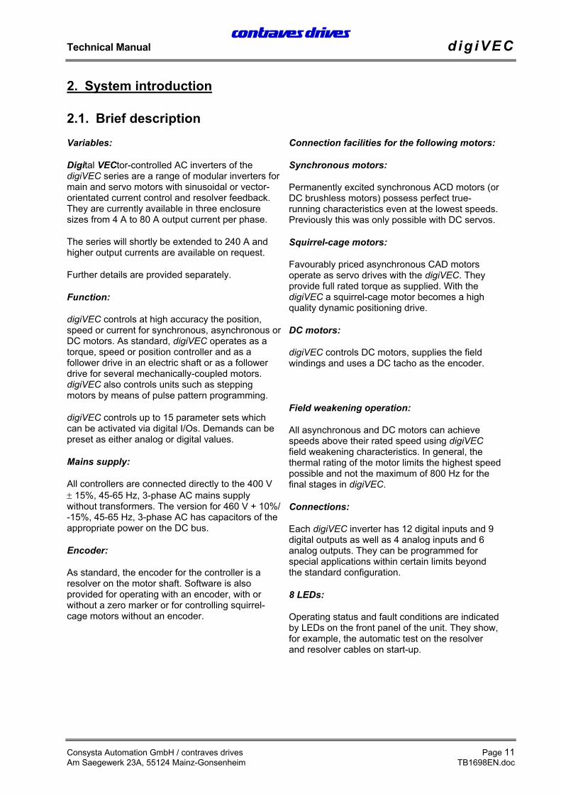
Digital VECtor-controlled AC inverters of thedigiVEC series are a range of modular inverters formain and servo motors with sinusoidal or vector-orientated current control and resolver feedback.They are currently available in three enclosuresizes from 4 A to 80 A output current per phase.
The series will shortly be extended to 240 A andhigher output currents are available on request.
Further details are provided separately.
Function:
digiVEC controls at high accuracy the position,speed or current for synchronous, asynchronous orDC motors. As standard, digiVEC operates as atorque, speed or position controller and as afollower drive in an electric shaft or as a followerdrive for several mechanically-coupled motors.digiVEC also controls units such as steppingmotors by means of pulse pattern programming.
digiVEC controls up to 15 parameter sets whichcan be activated via digital I/Os. Demands can bepreset as either analog or digital values.
Mains supply:
All controllers are connected directly to the 400 V± 15%, 45-65 Hz, 3-phase AC mains supplywithout transformers. The version for 460 V + 10%/-15%, 45-65 Hz, 3-phase AC has capacitors of theappropriate power on the DC bus.
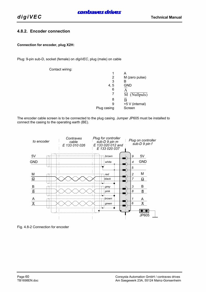
Encoder:
As standard, the encoder for the controller is aresolver on the motor shaft. Software is alsoprovided for operating with an encoder, with orwithout a zero marker or for controlling squirrel-cage motors without an encoder.
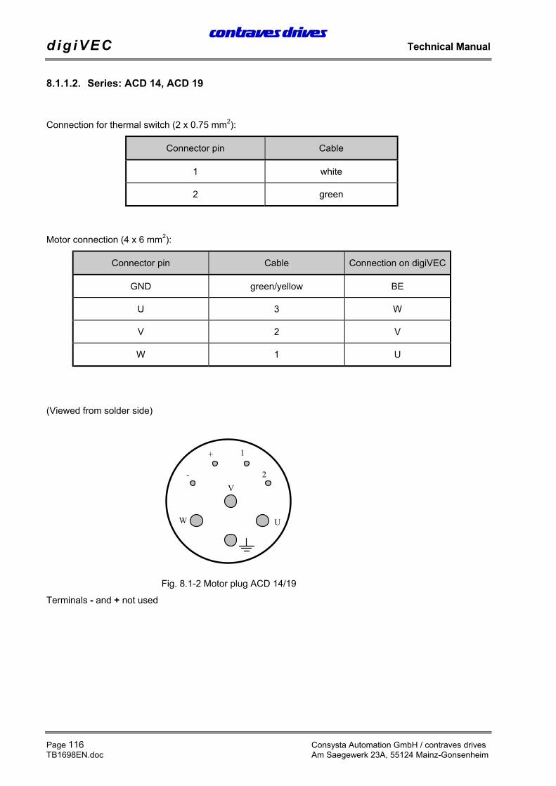
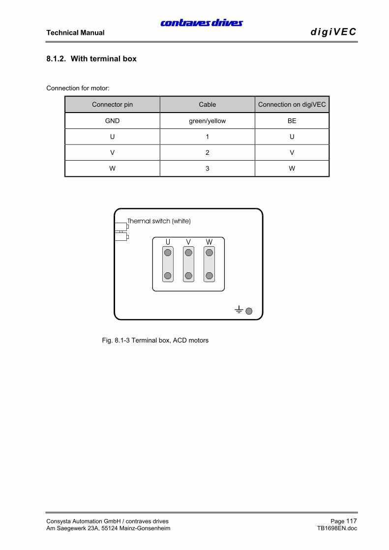
Connection facilities for the following motors:
Synchronous motors:
Permanently excited synchronous ACD motors (orDC brushless motors) possess perfect true-running characteristics even at the lowest speeds.Previously this was only possible with DC servos.
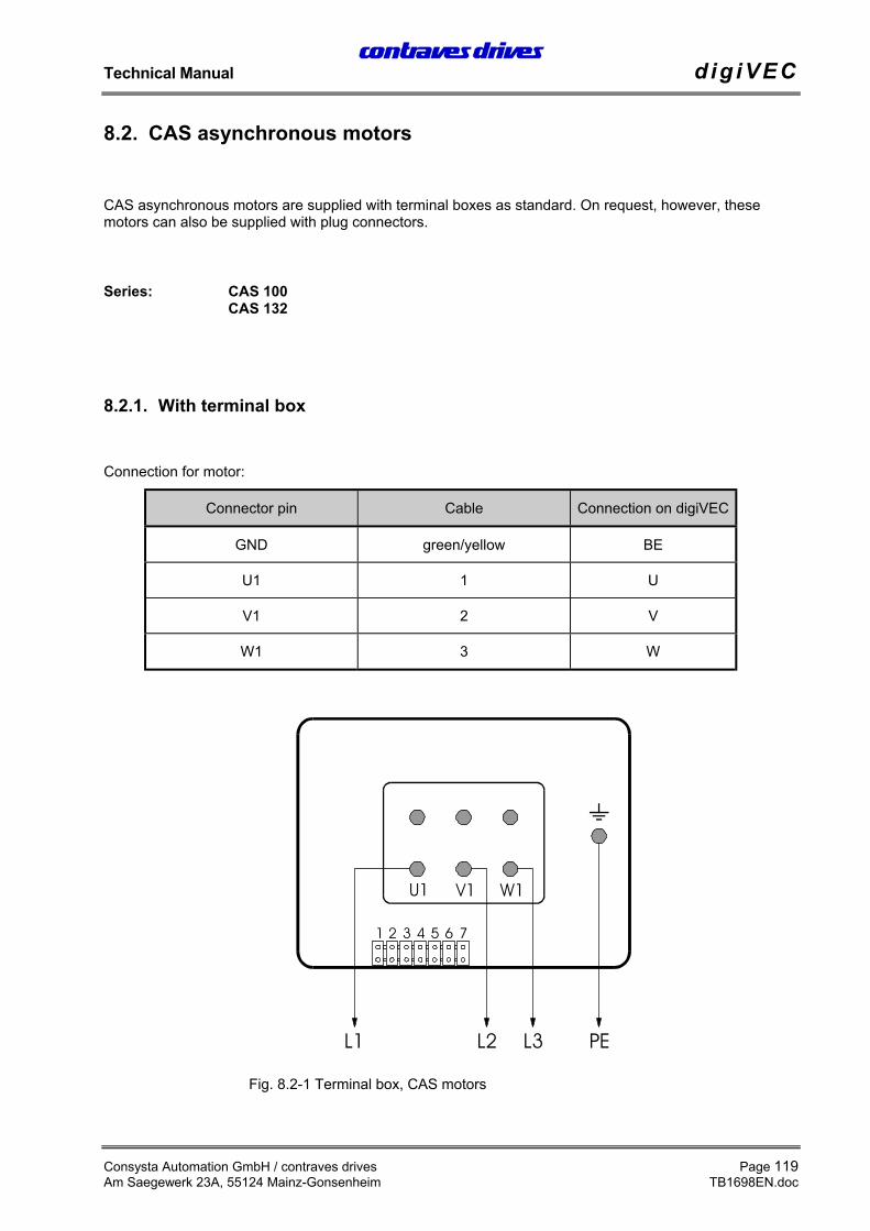
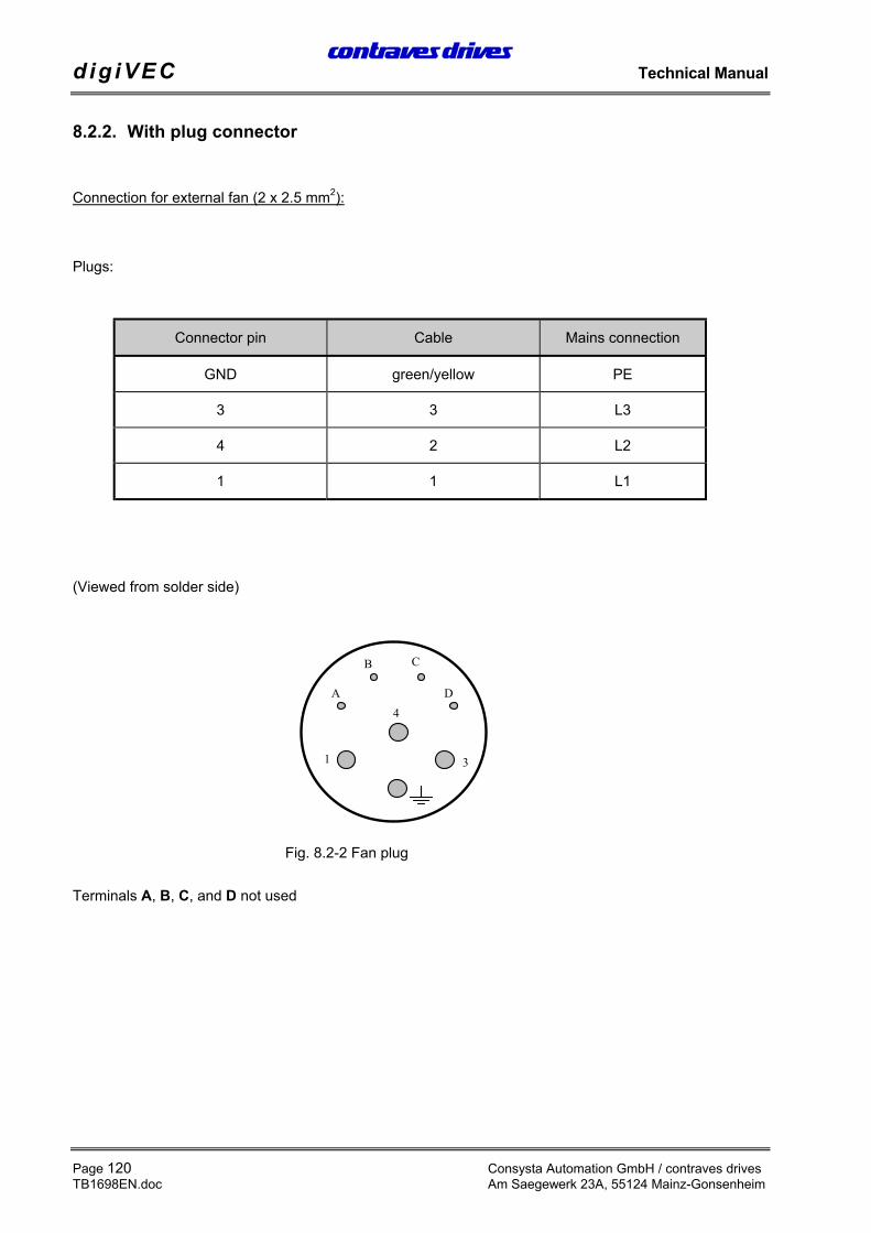
Squirrel-cage motors:
Favourably priced asynchronous CAD motorsoperate as servo drives with the digiVEC. Theyprovide full rated torque as supplied. With thedigiVEC a squirrel-cage motor becomes a highquality dynamic positioning drive.
DC motors:
digiVEC controls DC motors, supplies the fieldwindings and uses a DC tacho as the encoder.
Field weakening operation:
All asynchronous and DC motors can achievespeeds above their rated speed using digiVECfield weakening characteristics. In general, thethermal rating of the motor limits the highest speedpossible and not the maximum of 800 Hz for thefinal stages in digiVEC.
Connections:
Each digiVEC inverter has 12 digital inputs and 9digital outputs as well as 4 analog inputs and 6analog outputs. They can be programmed forspecial applications within certain limits beyondthe standard configuration.
8 LEDs:
Operating status and fault conditions are indicatedby LEDs on the front panel of the unit. They show,for example, the automatic test on the resolverand resolver cables on start-up.
digiVEC drives every motor particularly smoothlyand with high dynamics.
Analog signals are digitised using 18 bit resolution.The operating system runs in real time in amultitasking environment.
An adaptive control algorithm compensates for thetemperature dependence of important controllerparameters. The motor current is alwayssinusoidal. For this reason, speed is very stableand torque can be controlled accurately andlinearly.
Interfaces:
A MS-DOS PC with a 386 processor or better is tobe connected to the standard RS232 interface forconfiguration, commissioning and diagnostics.During operation all parameters can be adjusted bydigiVEC through this interface. PC software for thestandard configuration is supplied with the unit.
Multiple drives can be interlinked through anRS485 interface.
Ancillary equipment
• Software for spindle positioning, indexing,winding at constant tension, electronicgearboxes, metering pistons with immediatereversing and many other applications
• Encoder simulation card for simulating anormal signal from a mechanical encoder,with the facility to set any full number ofpulses up to max. 1,024 pulses per pair ofpoles in the resolver.
• Voltage resistance up to max. 460 V for themains supply.
• Interface to CAN bus and Sercos (in thenear future).
• Supplementary card with 24 digital inputs oroutputs (configurable) for applications.
2.4.1. Three-phase bridge rectifier with subsequent voltage link
The mains (L1, L2 and L3) are supplied through an uncontrolled 3-phase bridge rectifier. The resulting DCvoltage (approx. 560 V) is smoothed by the capacitor battery on the DC link.
The link circuit acts as an energy buffer to decouple the mains from the motor. The two connections for theDC bus are fed to terminals (DC bus ZP and ZN) to allow energy transfer as required when operatingmultiple inverter units.
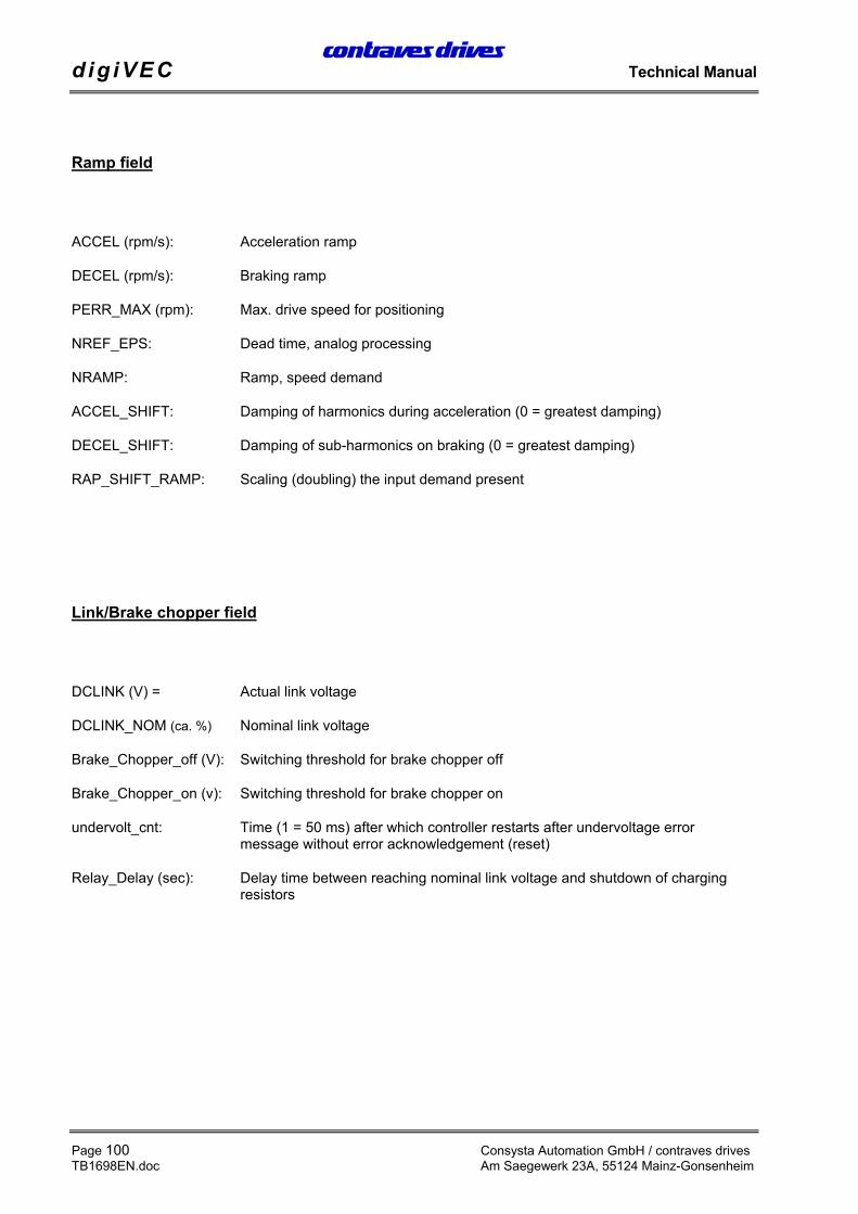
The voltage on the link is monitored to relieve the power electronics. The minimum start-up value is definedwith the parameter DCLINK_NOM (approx. %). The shutdown value is 100 V lower (hysteresis).
The brake module (chopper) is also on the link. This brake chopper switches on the braking resistor at alink voltage of 675 V (depending on the mains input voltage). The braking resistor converts the energy fedback from the motor during braking into heat. If the link voltage falls below a certain lower limit the brakingresistor is switched off again.Brake_Chopper_off(V): and Brake_Chopper_on(V): allow this process to be set up as required (thesetting depending on the mains input voltage).
The drive controller can be operated with the following feedback systems:
Resolver (standard design):
Rotor position, speed actual value and direction of rotation are determined by a resolver on the motor.Resolver signals are fed through plug X2L to the RDC resolver signal processing unit where mainly thesignals POSSPEED (rpm)=(speed actual value) and PACT_LOW= as well as PACT_HIGH= (positionactual values) are used for position and speed control as well as coordinates transformation.
Encoder:
An encoder can be connected to digiVEC through plug X2H. The signals read in are designated asENC_COUNT in the block circuit diagram. The signals ENC_SPEED and ENC_DELTA are formed fromthe encoder signal. The signal ENC_DELTA corresponds to the incremental increase in the encoder.ENC_DELTA can be applied to the position controller as the demand and ENC_COUNT as the actualvalue.
• ENC_DELTA Demand for position controller through the encoder signal(Delta signal: See description of encoder above)
• ENC_SPEED Demand for position controller through the encoder signal
• 0 Demand = 0
• NREF, JOG_RIGHT, Internal demand presetJOG_LEFT
NMUX_VEL Input multiplexer speed controller:
• ANCHA1 Demand preset through an analog value via terminal X1:27 and X1:28
• ANCHA2 Demand preset through an analog value via terminal X1:25 and X1:26
• 0 Demand for speed controller = 0
• NREF, JOG_RIGHT, Internal demand presetJOG_LEFT
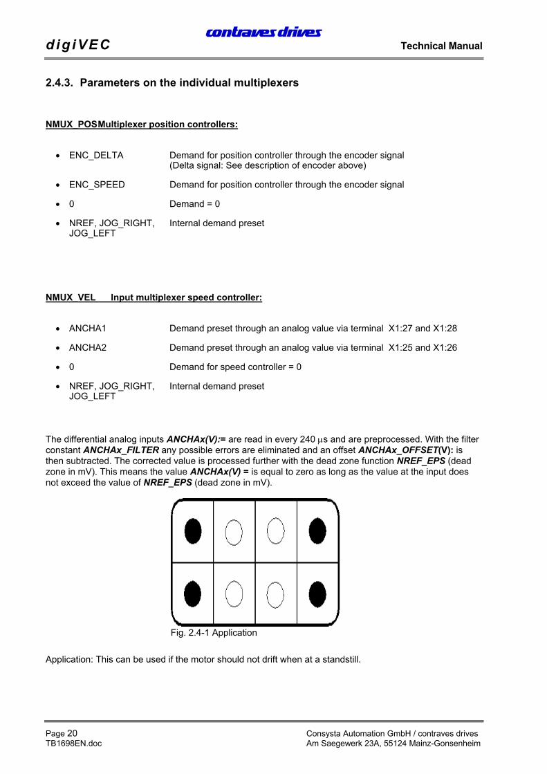
The differential analog inputs ANCHAx(V):= are read in every 240 µs and are preprocessed. With the filterconstant ANCHAx_FILTER any possible errors are eliminated and an offset ANCHAx_OFFSET(V): isthen subtracted. The corrected value is processed further with the dead zone function NREF_EPS (deadzone in mV). This means the value ANCHAx(V) = is equal to zero as long as the value at the input doesnot exceed the value of NREF_EPS (dead zone in mV).
Application: This can be used if the motor should not drift when at a standstill.
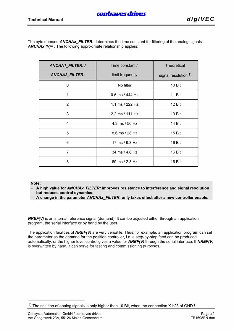
The byte demand ANCHAx_FILTER: determines the time constant for filtering of the analog signalsANCHAx (V)= . The following approximate relationship applies:
ANCHA1_FILTER: / Time constant / Theoretical
ANCHA2_FILTER: limit frequency signal resolution 1)
0 No filter 10 Bit
1 0.6 ms / 444 Hz 11 Bit
2 1.1 ms / 222 Hz 12 Bit
3 2.2 ms / 111 Hz 13 Bit
4 4.3 ms / 56 Hz 14 Bit
5 8.6 ms / 28 Hz 15 Bit
6 17 ms / 9.3 Hz 16 Bit
7 34 ms / 4.6 Hz 16 Bit
8 69 ms / 2.3 Hz 16 Bit
Note:− A high value for ANCHAx_FILTER: improves resistance to interference and signal resolution
but reduces control dynamics.− A change in the parameter ANCHAx_FILTER: only takes effect after a new controller enable.
NREF(V) is an internal reference signal (demand). It can be adjusted either through an applicationprogram, the serial interface or by hand by the user.
The application facilities of NREF(V) are very versatile. Thus, for example, an application program can setthe parameter as the demand for the position controller, i.e. a step-by-step feed can be producedautomatically, or the higher level control gives a value for NREF(V) through the serial interface. If NREF(V)is overwritten by hand, it can serve for testing and commissioning purposes.
1) The solution of analog signals is only higher then 10 Bit, when the connection X1:23 of GND !
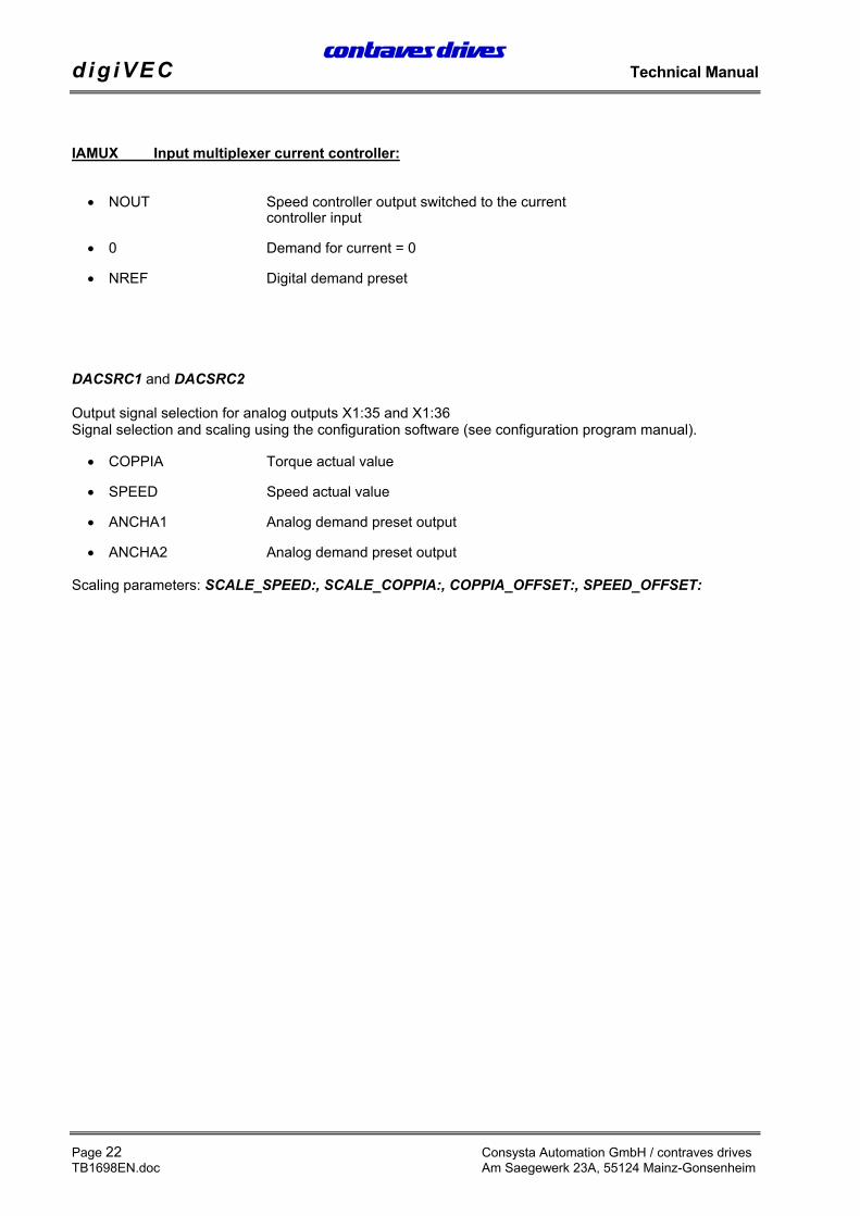
• NOUT Speed controller output switched to the currentcontroller input
• 0 Demand for current = 0
• NREF Digital demand preset
DACSRC1 and DACSRC2
Output signal selection for analog outputs X1:35 and X1:36Signal selection and scaling using the configuration software (see configuration program manual).
An int ernally generated ramp can be used to adapt the dynamics to the mechanical limits of the machine.
A ramp can be applied or removed using flag settings (see section 5.7, Function of individual flags).Acceleration ACCEL (rpm/s): and braking DECEL (rpm/s): are freely definable.
NMAX (rpm): / NMIN (rpm):
These two values limit the maximum speed of the motor (limit switch function).NMAX (rpm): limits the positive maximum speed and NMIN (rpm): limits the negative maximum speed.The values can be activated and de-activated through the digital inputs.
If the motor speed exceeds the value of NMAX (rpm): or NMIN (rpm): by approx. 300 rpm, the inverter isno longer able to control the speed (due to a fault or overload) and the monitor disables the controller.
2.4.5. Control: Position, Speed, Current controller
The control uses a cascade structure with position, speed and current control (torque and flux). The inputsignals for the control can be determined by the user as required using the internal multiplexersNMUX_POS, NMUX_VEL and IAMUX. They are processed in different cycles so that control algorithms donot affect each other.
Position control : Every 960 µs corresponding to:1.04 kHzSpeed control : Every 480 µs corresponding to:2.08 kHzCurrent control : Every 240 µs corresponding to:4.16 kHz
Speed control
Depending on the setting of the multiplexer NMUX_VEL the demand for the speed controller can be ananalog value ANCHAx(V)=, a digital preset NREF(V): or increments of an encoder through input X2H(ENC_SPEED) which can be scaled by RAP_VEL (rpm/V): and RAP_SHIFT_VEL.
Conversion of internal units into rpm:
[ ]n rpm NREF RAP VELRPZ
RAP SHIFT VEL
=× × × ×_ , ,_ _0 5 2 1 70807
(RPZ = resolver number of pairs of poles)
Actual value feedback is the speed of the motor POSSPEED (rpm)= calculated from the resolver signals.
Current control for torque and flux:
The motor current is divided into two current components at 90 degrees to each other which are affectedseparately. Thus with an asynchronous motor, just like with a DC motor, exciter flux and torque can becontrolled independently (field-orientated control).
The currents of phases U and V taken up by the motor are measured, converted into digital signals (ADC)and then formed into the components for flux IF_ACT and torque IA_ACT at an angle of 90 degrees toeach other by means of coordinates transformation and are used as actual value feedback for the currentcontroller.
The higher level speed control circuit is to be deactivated for current or torque control. According to theblock circuit diagram in section 2.3 the current multiplexer IAMUX is to be set to NREF for this purpose.The absolute demand is preset through NREF.
The position controller is switched in or out with Flag.1 or FLAG_POS: = 02HEX. If position control is on,Flag.2 can be used to activate feed forward (see section 5.7, Funktion of individuel flags).
According to the block circuit diagram in section 2.3 this provides preliminary speed control, i.e. thedemand for the position control is applied directly to the speed control circuit, whereby the control becomesmore dynamic (faster).
Position control is activated using parameter CMDREF: = 04 HEX before firing is enabled.
The actual value is read in automatically as the demand when the controller is enabled, to preventuncontrolled motor starting.
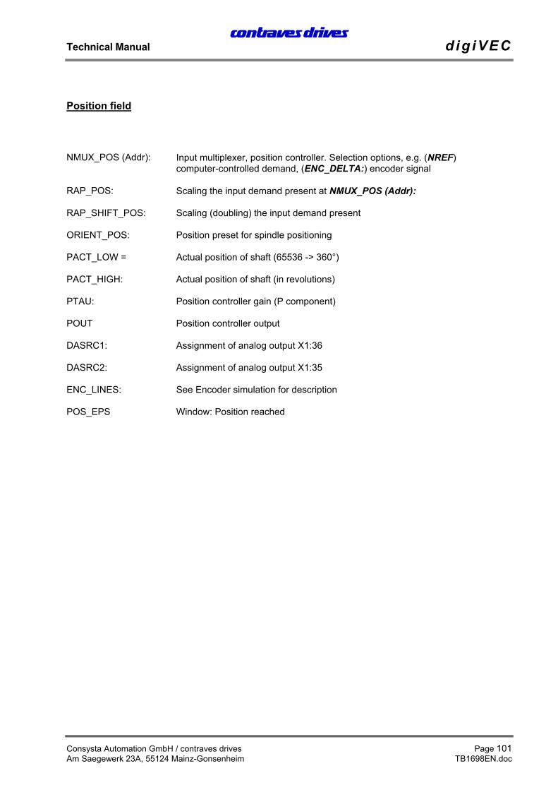
Depending on the setting of multiplexer NMUX_POS (Adr): the demand preset for the position controllercan be through an encoder signal ENC_SPEED, an absolute position PREF_HIGH, PREF_LOW etc.,which can be scaled by RAP_POS : and RAP_SHIFT_POS :
Factor: RAP POS
RPZ
RAP SHIFT POST_ _ _××2
32767
(RPZ = Resolver number of pairs of poles)
You can choose between the signals PACT_LOW and PACT_HIGH (position processing by the resolver)or ENC_COUNT, ENC_HIGH and ENC_LOW as the actual value feedback. Thus, for example, theposition can be set to the position of a roll driven by a gearbox.
Speed acceleration and deceleration can be defined by the parameters ACCEL (rpm/s): and DECEL(rpm/s):. In addition it is possible to preset a maximum search speed for reaching the position usingPERR_MAX (rpm):.
Position controller gain is set with PTAU. The value of PTAU adjusts the proportional component of thecontroller (the default value for PTAU is 8).
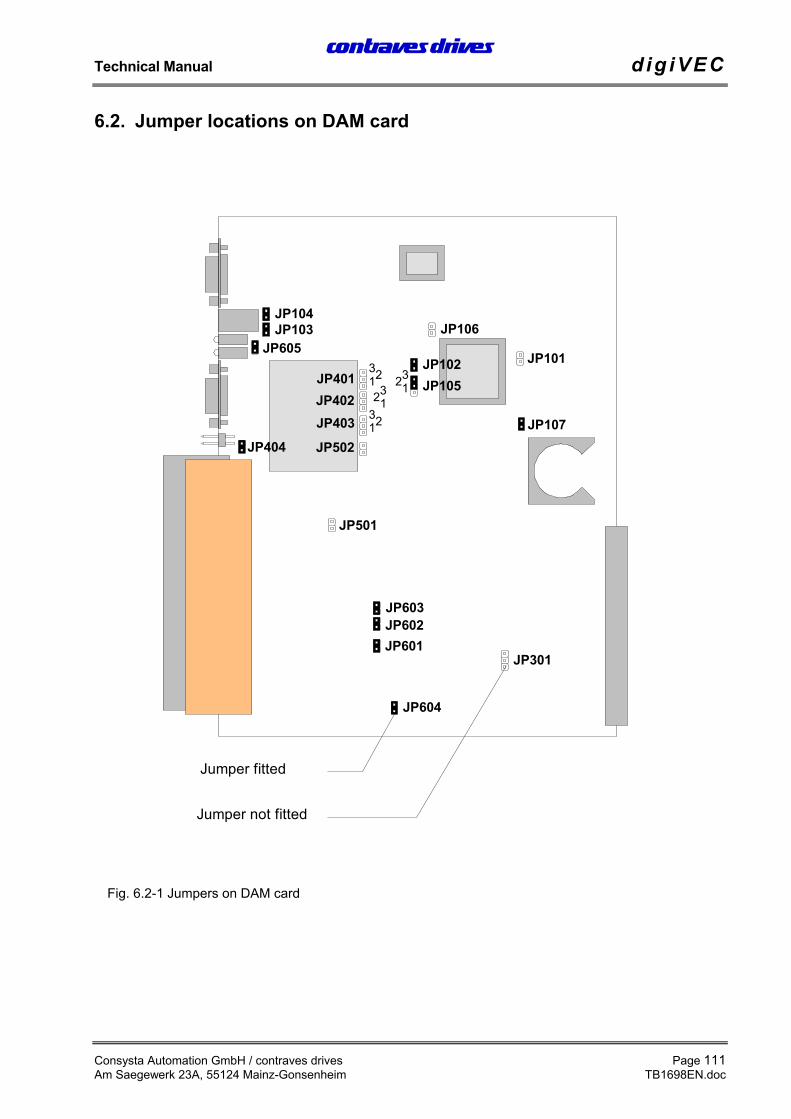
If an encoder signal is to be used for demand preset it is important to ensure that jumper JP404 for theencoder supply is set on the DAM card (internal supply at 5 V DC). The input of position multiplexerNMUX_POS must be set to ENC_SPEED. The encoder input is activated with FLAG 4. The number of linemarkings on the encoder according to the rating plate is to be entered in parameter ENC_LPR:.
A special facility in position control is spindle positioning. If the system switches at input X1:20 from speedcontrol to position control (only when firing is switched on), the value of ORIENT_POS is preset as theposition. For this purpose, multiplexer NMUX_POS (Adr): must be set to R0.
The ramp function DECEL (rpm/s): now applies the actual speed (from the speed control) to the positionORIENT_POS. This prevents the spindles being set to the required angle position with the oppositedirection of rotation.
By setting input X1:19 (or CMDREF: = 08 HEX if command multiplexer CMDMUX: is set to input via theconfiguration program) the momentary position of the spindles is read in parameter ORIENT_POS with thedrive at a standstill and is therefore available as the demand for positioning.
With the application software it is possible to read in up to 4 spindle positions.
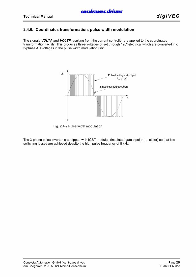
The signals VOLTA and VOLTF resulting from the current controller are applied to the coordinatestransformation facility. This produces three voltages offset through 120º electrical which are converted into3-phase AC voltages in the pulse width modulation unit.
The 3-phase pulse inverter is equipped with IGBT modules (insulated gate bipolar transistor) so that lowswitching losses are achieved despite the high pulse frequency of 8 kHz.
Parameters and the operating system software are stored in three memory areas.
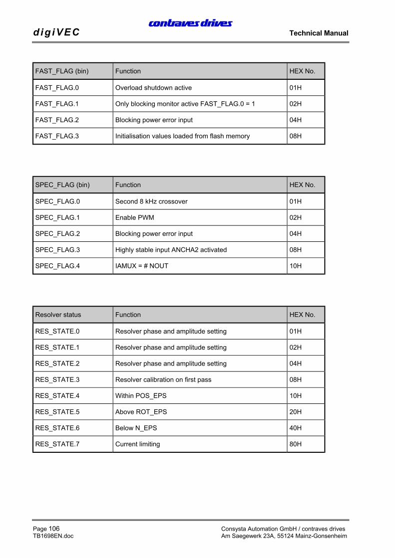
digiVEC operates with the latest data (parameters) in the work RAM.When the controller supply voltage is switched on or after a system reset, depending on the status of theFAST_FLAG.3 the data in the work RAM is compared with the Init_RAM (FAST_FLAG: 00H) or with theFlash memory (FAST_FLAG: 04H). If the content is different, the work RAM is updated from the relevantmemory.
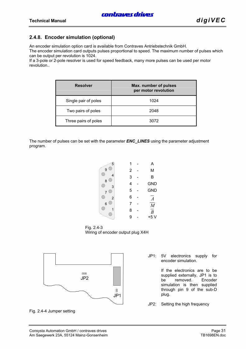
2.4.8. Encoder simulation (optional)An encoder simulation option card is available from Contraves Antriebstechnik GmbH.The encoder simulation card outputs pulses proportional to speed. The maximum number of pulses whichcan be output per revolution is 1024.If a 3-pole or 2-pole resolver is used for speed feedback, many more pulses can be used per motorrevolution..
Resolver Max. number of pulsesper motor revolution
Single pair of poles 1024
Two pairs of poles 2048
Three pairs of poles 3072
The number of pulses can be set with the parameter ENC_LINES using the parameter adjustmentprogram.
2.5. Intended useThe drive systems are designed and built according to the state of the art and accepted safety regulations.However, operation may cause risk to life and limb of operators or third parties and the drive may affectmachines, plant or other items.
The drive system may only be operated when in perfect condition in accordance with the commissioningand operating instructions, and operators must be aware of the safety aspects and risks involved. Safe andreliable operation of the control requires correct transport, storage and installation as well as carefuloperation and maintenance.In particular, any faults which could affect safety must be corrected immediately.
The drive systems are intended exclusively for controlling machines and plant.
Any other use is inappropriate and the manufacturer accepts no liability for any resultant damage or loss.The instructions on the mechanical and electrical design, commissioning and operation given in thismanual must be observed for correct operation of the drive systems.
• The room should be dust-free if possible (for build-in units and cubicle-mounted units with air inlet atbase without air filter).
• The ambient temperature must be between 0 ... 40ºC.
• The relative air humidity may not exceed 90% (no condensation).
• The air supply may not contain corrosive gas.
• digiVEC produces power losses and heats the environment. Adequate spacing from heat-sensitiveequipment is essential.
• The air flow may not be restricted. Minimum clearances of 100 mm must be provided at air inlets andoutlets.
• digiVEC must be protected against magnetic and electrical interference.
• Special filter modules are provided for digiVEC to comply with EMC guidelines. They are availablefrom Contraves Antriebstechnik in Mainz and comply with the appropriate regulations.
digiVEC is to be checked for any damage in transit after unpacking and before commissioning. All plug andscrew connections are to be checked to ensure they are tight.
Check that the connections required for application have been made and are correct (digital and analoginputs and outputs etc.) before switching on the primary voltage.
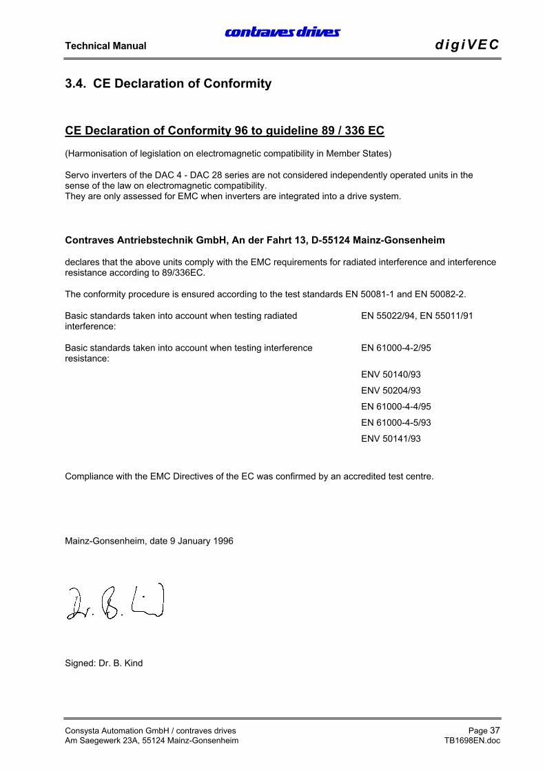
CE Declaration of Conformity 96 to guideline 89 / 336 EC
(Harmonisation of legislation on electromagnetic compatibility in Member States)
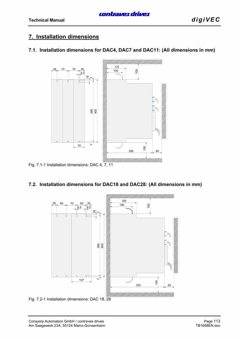
Servo inverters of the DAC 4 - DAC 28 series are not considered independently operated units in thesense of the law on electromagnetic compatibility.They are only assessed for EMC when inverters are integrated into a drive system.
Contraves Antriebstechnik GmbH, An der Fahrt 13, D-55124 Mainz-Gonsenheim
declares that the above units comply with the EMC requirements for radiated interference and interferenceresistance according to 89/336EC.
The conformity procedure is ensured according to the test standards EN 50081-1 and EN 50082-2.
Basic standards taken into account when testing radiatedinterference:
EN 55022/94, EN 55011/91
Basic standards taken into account when testing interferenceresistance:
EN 61000-4-2/95
ENV 50140/93
ENV 50204/93
EN 61000-4-4/95
EN 61000-4-5/93
ENV 50141/93
Compliance with the EMC Directives of the EC was confirmed by an accredited test centre.
The monitor program described below is to be used for communication between digiVEC and a PC.Two versions are available: 1. In German. 2. In English.System requirements: IBM-compatible PC (XT/AT) with MS-DOS operating system.All files required for the configuration program are provided on the diskette supplied.
The program consists of the following files:
• START.BAT Normal start-up program with English user interface
• STARTGER.BAT German user interface
• MOT.CFG Last configuration is saved - screen color etc.
• MOTGER.EXE Program in German
• MOTUS.EXE Program in English
• PARALIS.EXE Parameter files can be printed using a specific command
• MOTGER.HLP Help file in German
• MOTUS.HLP Help file in English
• *.LBY Library containing all parameters (required if you want to set newparameters)
• *.PFL Profiles
• MUXLIB.LBY Multiplexer library
• HINWEIS.TXT Program installation notes
4.1.1. Program installationThe above files should be copied into a directory C:\CONTRAVS\ on your hard drive.No special driver is needed.
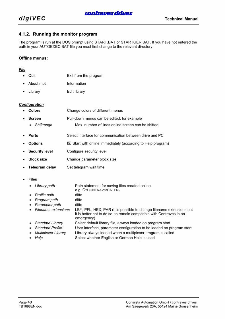
4.1.2. Running the monitor programThe program is run at the DOS prompt using START.BAT or STARTGER.BAT. If you have not entered thepath in your AUTOEXEC.BAT file you must first change to the relevant directory.
Offline menus:
File• Quit Exit from the program
• About mot Information
• Library Edit library
Configuration• Colors Change colors of different menus
• Screen Pull-down menus can be edited, for example• Shiftrange Max. number of lines online screen can be shifted
• Ports Select interface for communication between drive and PC
• Options Start with online immediately (according to Help program)
• Security level Configure security level
• Block size Change parameter block size
• Telegram delay Set telegram wait time
• Files• Library path Path statement for saving files created online
e.g. C:\CONTRAVS\DATEN\• Profile path ditto• Program path ditto• Parameter path ditto• Filename extensions LBY, PFL, HEX, PAR (It is possible to change filename extensions but
it is better not to do so, to remain compatible with Contraves in an emergency)
• Standard Library Select default library file, always loaded on program start• Standard Profile User interface, parameter configuration to be loaded on program start• Multiplexer Library Library always loaded when a multiplexer program is called• Help Select whether English or German Help is used
The profile should always be loaded and the configuration set after running the program for thefirst time.
• Save Save settings
• Save as Save under a different filename
Online• Start online Start online operation
The following menus are to be noted in online operation:
File• Open profile Open the profile containing the user interface, i.e. the number of
parameters and their locations.
• Reload profile Reload the original user interface
• Save profile Save profile under same name after editing
Attention! Do not overwrite the original profiles, so that you cancontact Contraves in an emergency (see Save Profile As)
• Save profile As Save the profile under a different name
• ESC: Close menu Close pull-down menu
• Quit online Exit from online operation (another user interface is opened)
Mode• Command value edit Standard setting for checking and adjusting parameter values
• Display only Display only, no parameter adjustment possible
• Clear Clear parameters.(First click on Clear Parameters parameters are cleared) or (click on Parameter Del parameter is cleared)
Attention! The parameters are cleared until another menu option isselected!!!
• Move Move parameters (click on the Parameter, hold down the left mouse key and then move)If you click on the parameter at the end of the field, the field can be enlarged or reduced to the right or left
• Parameter specific. Edit parameter names, formats etc. Can also be called with F8.
Attention! The original name should be noted in brackets tomaintain compatibility for service purposes!
Attention! Only the description may be edited! Do not change the pin no. as otherwisethe addresses will no longer match the parameters!
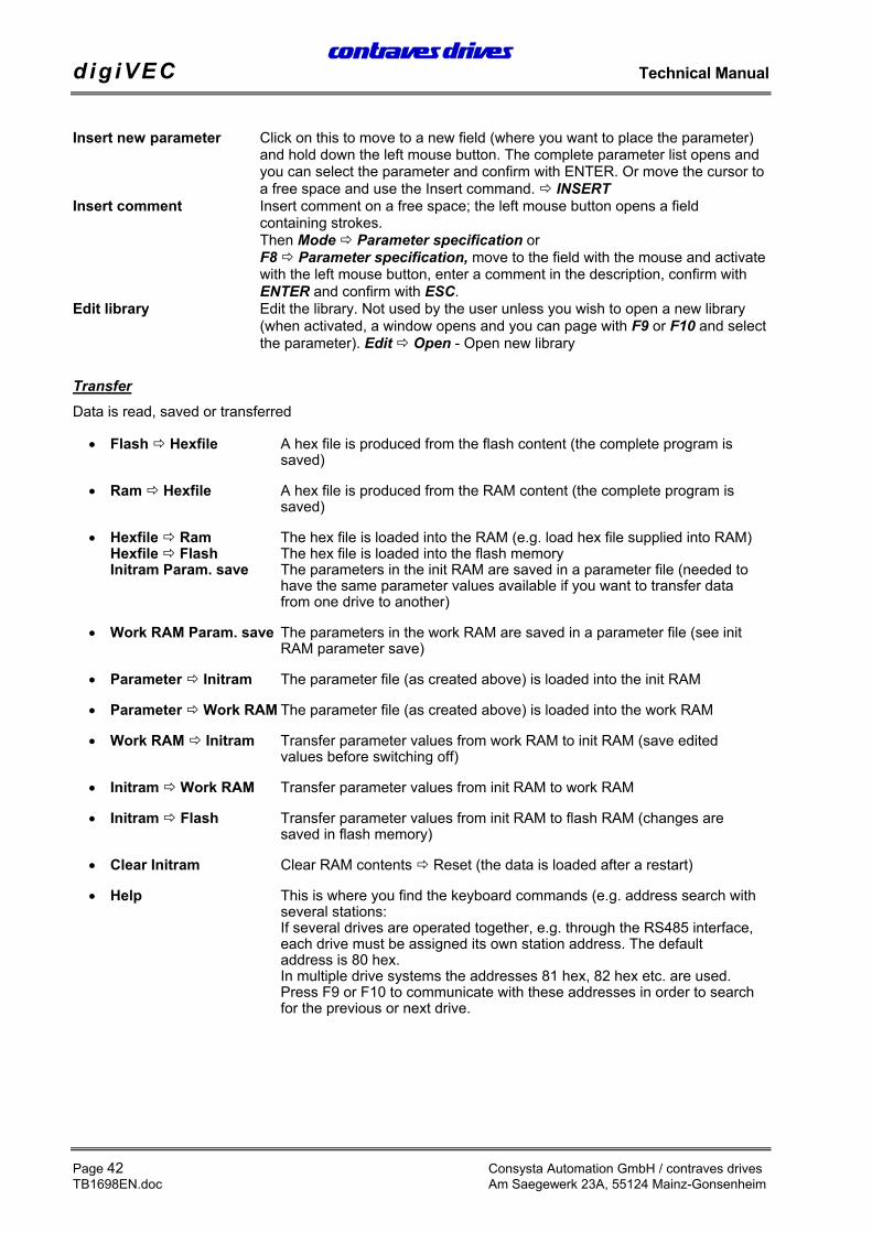
Insert new parameter Click on this to move to a new field (where you want to place the parameter)and hold down the left mouse button. The complete parameter list opens andyou can select the parameter and confirm with ENTER. Or move the cursor toa free space and use the Insert command. INSERT
Insert comment Insert comment on a free space; the left mouse button opens a fieldcontaining strokes.Then Mode Parameter specification orF8 Parameter specification, move to the field with the mouse and activatewith the left mouse button, enter a comment in the description, confirm withENTER and confirm with ESC.
Edit library Edit the library. Not used by the user unless you wish to open a new library(when activated, a window opens and you can page with F9 or F10 and selectthe parameter). Edit Open - Open new library
TransferData is read, saved or transferred
• Flash Hexfile A hex file is produced from the flash content (the complete program is saved)
• Ram Hexfile A hex file is produced from the RAM content (the complete program is saved)
• Hexfile Ram The hex file is loaded into the RAM (e.g. load hex file supplied into RAM)Hexfile Flash The hex file is loaded into the flash memoryInitram Param. save The parameters in the init RAM are saved in a parameter file (needed to
have the same parameter values available if you want to transfer data from one drive to another)
• Work RAM Param. save The parameters in the work RAM are saved in a parameter file (see init RAM parameter save)
• Parameter Initram The parameter file (as created above) is loaded into the init RAM
• Parameter Work RAM The parameter file (as created above) is loaded into the work RAM
• Work RAM Initram Transfer parameter values from work RAM to init RAM (save edited values before switching off)
• Initram Work RAM Transfer parameter values from init RAM to work RAM
• Initram Flash Transfer parameter values from init RAM to flash RAM (changes are saved in flash memory)
• Clear Initram Clear RAM contents Reset (the data is loaded after a restart)
• Help This is where you find the keyboard commands (e.g. address search with several stations:If several drives are operated together, e.g. through the RS485 interface, each drive must be assigned its own station address. The default address is 80 hex.In multiple drive systems the addresses 81 hex, 82 hex etc. are used. Press F9 or F10 to communicate with these addresses in order to search for the previous or next drive.
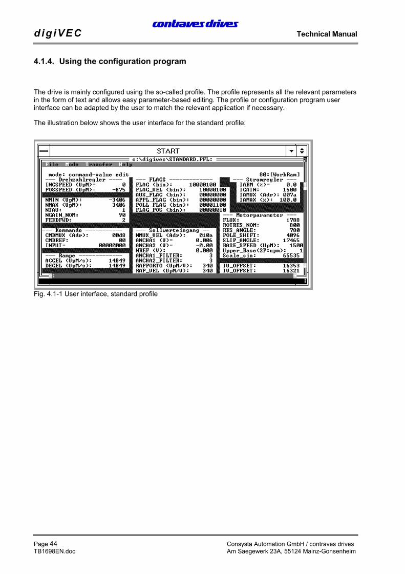
The drive is mainly configured using the so-called profile. The profile represents all the relevant parametersin the form of text and allows easy parameter-based editing. The profile or configuration program userinterface can be adapted by the user to match the relevant application if necessary.
The illustration below shows the user interface for the standard profile:
The integral Help system explains software operation and the meaning of individual parameters.
The relevant Help page is activated according to the cursor position by pressing function key F1.Further help is available for highlighted parts of the text.
The following points should help to prevent wiring problems and are intended as guidelines for EMC-compliant wiring.
• The cross-section of the protective conductor in the feed cable to the cubicle must be at least 10 mm²copper or a second protective conductor must be laid in parallel according to VDE 0160 section6.5.2.1 due to the current induced by the inverter (> 3.5 mA) through the protective earth conductorPE, according to DIN VDE 0160.
• At higher ratings the minimum cross-section of the protective conductor must be suitably related tothe cross-section of the outer conductor. See DIN 57100 Part 540 / VDE 0100 Part 540 Table 2.
• The currents induced by the inverter can be up to 100 mA. Operation with 30 mA FI protectionswitches is therefore not possible.
• Avoid using a shared terminal block for mains input and motor output.
• Control signal cables are to be screened and, if necessary, individually twisted pairs of conductorsinside the screen are to be screened again.
• Control signals are to be transferred using twisted pairs of conductors (100 twists per metre).
Attention! The unit remains live for more than one minute after it is switched off. Beforeopening the unit or touching live parts it is essential to check that the DC link has discharged(terminal ZN/ZP) -> link voltage up to 600 V DC.
To avoid faults the cables used are to be laid in three separate groups. These groups should runseparately or be placed in separate cable ducts. Cables should be as short as possible.
Group the cable as follows:
• Mains cables
• Motor cables
• Signal wiring (encoder, resolver, controller, signal feeds etc.)
If units which contain power electronics are installed in or close to switchgear systems or are operated onthe same mains supply, interference suppression will be required for the switchgear systems.
• Coils in contactors, switchgear and relay combinations are to be connected with RC components ordiodes
• Lines generating interference (power circuits, contactor control circuits etc.) are to be laid separatelyand spaced sufficiently from control cables
• The conductor for motor temperature protection may not be located in the resolver cable
• When mounting plates are used, ensure a good electrically conducting contact.
• If mounting plates with a surface finish are used, the finish must be removed at the connection pointsfor screens, inverters and mains filters to produce a good low impedance connection.
• If several mounting plates are used they are to be electrically connected using generously sizedcopper straps.
• Motor cables are to be screened and connected at both ends.
• Connect the screen to the inverter PE terminal.
• If a motor with a terminal box is used, the end of the screen is to be connected to the PE terminal onthe motor. (If a Contraves motor with plug connectors is used, this connection is already providedthrough the plug).
• Screens are also to be firmly and generously connected to the mounting plate.
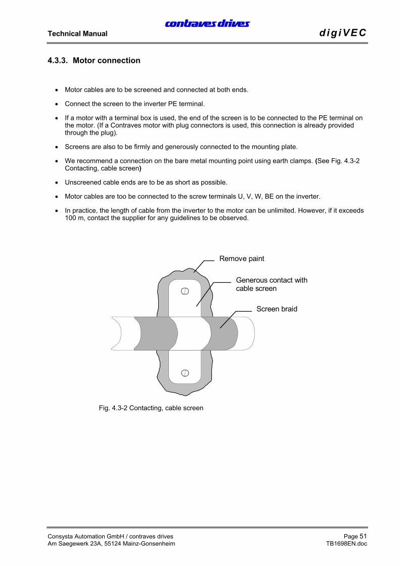
• We recommend a connection on the bare metal mounting point using earth clamps. (See Fig. 4.3-2Contacting, cable screen)
• Unscreened cable ends are to be as short as possible.
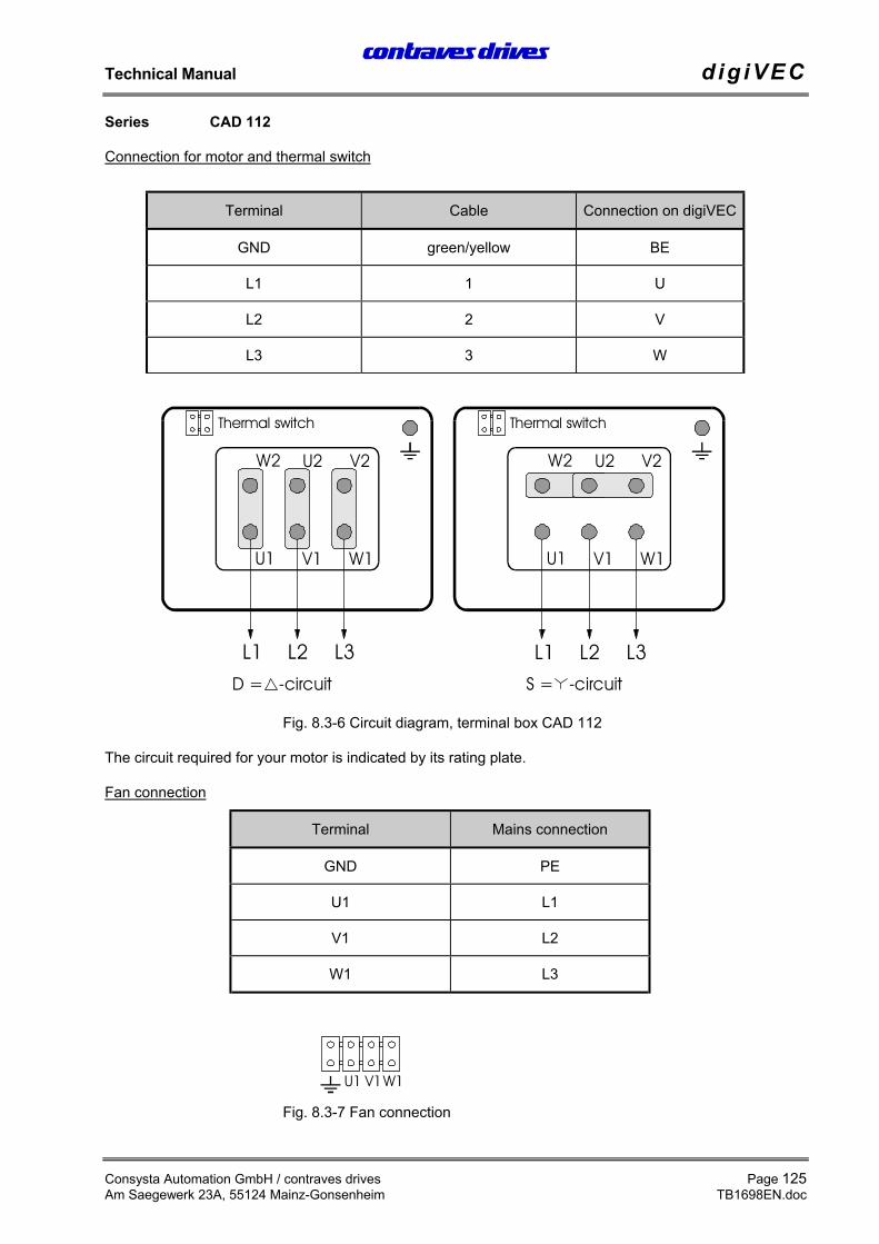
• Motor cables are too be connected to the screw terminals U, V, W, BE on the inverter.
• In practice, the length of cable from the inverter to the motor can be unlimited. However, if it exceeds100 m, contact the supplier for any guidelines to be observed.
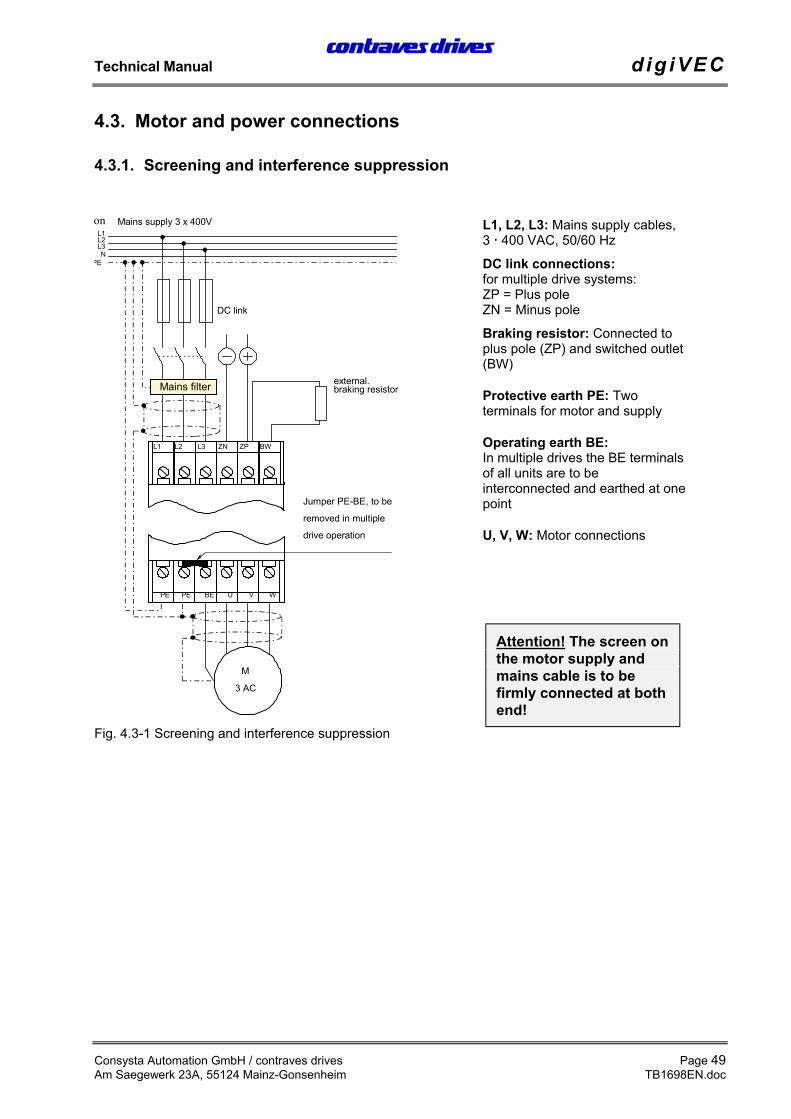
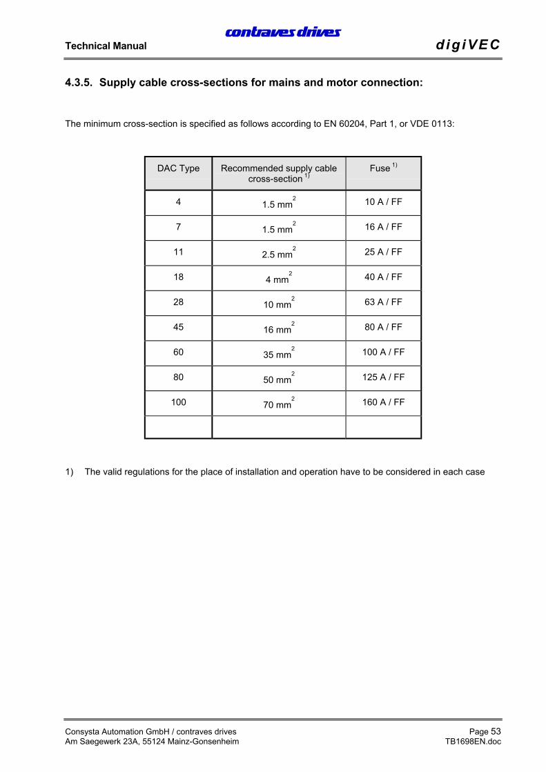
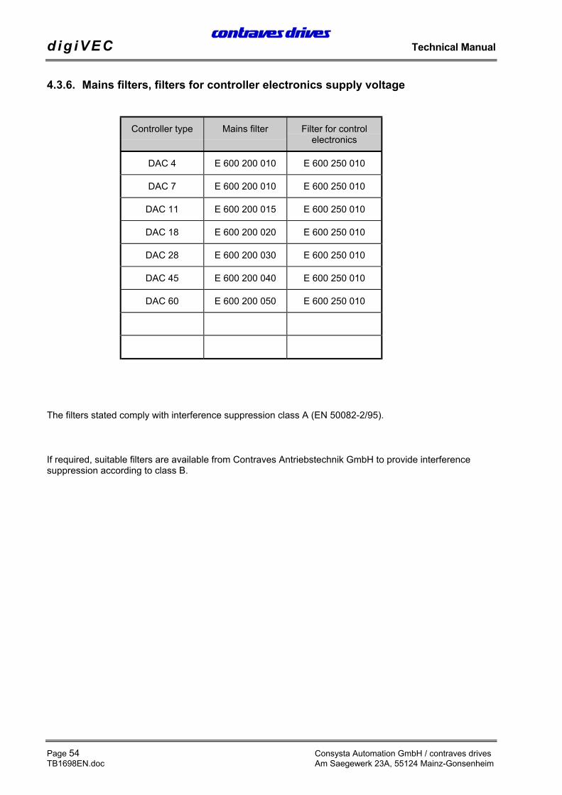
• Use the cable cross-section for the supply cables according to the type of controller used (seesection 4.3.5 Supply cable cross-sections for mains and motor connection:).
• The controller mains filter is to be used.
• Connect the mains cables to terminals L1, L2 and L3 on the inverter.
• The PE cable is connected to terminal PE at the base of the inverter.
• Connect the screen correctly (see motor connections).
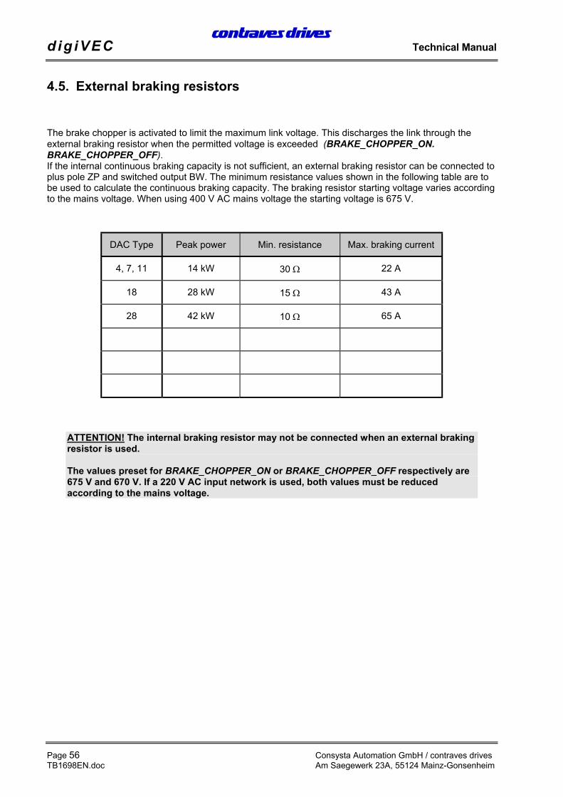
The brake chopper is activated to limit the maximum link voltage. This discharges the link through theexternal braking resistor when the permitted voltage is exceeded (BRAKE_CHOPPER_ON.BRAKE_CHOPPER_OFF).If the internal continuous braking capacity is not sufficient, an external braking resistor can be connected toplus pole ZP and switched output BW. The minimum resistance values shown in the following table are tobe used to calculate the continuous braking capacity. The braking resistor starting voltage varies accordingto the mains voltage. When using 400 V AC mains voltage the starting voltage is 675 V.
DAC Type Peak power Min. resistance Max. braking current
4, 7, 11 14 kW 30 Ω 22 A
18 28 kW 15 Ω 43 A
28 42 kW 10 Ω 65 A
ATTENTION! The internal braking resistor may not be connected when an external brakingresistor is used.
The values preset for BRAKE_CHOPPER_ON or BRAKE_CHOPPER_OFF respectively are675 V and 670 V. If a 220 V AC input network is used, both values must be reducedaccording to the mains voltage.
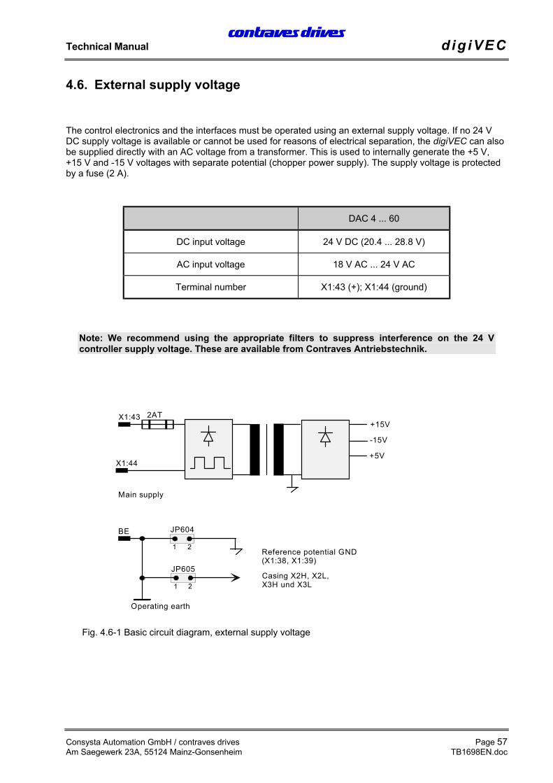
The control electronics and the interfaces must be operated using an external supply voltage. If no 24 VDC supply voltage is available or cannot be used for reasons of electrical separation, the digiVEC can alsobe supplied directly with an AC voltage from a transformer. This is used to internally generate the +5 V,+15 V and -15 V voltages with separate potential (chopper power supply). The supply voltage is protectedby a fuse (2 A).
DAC 4 ... 60
DC input voltage 24 V DC (20.4 ... 28.8 V)
AC input voltage 18 V AC ... 24 V AC
Terminal number X1:43 (+); X1:44 (ground)
Note: We recommend using the appropriate filters to suppress interference on the 24 Vcontroller supply voltage. These are available from Contraves Antriebstechnik.
JP605
1 2
X1:43+15V
X1:44
JP604
1 2
BE
-15V
+5V
Main supply
Casing X2H, X2L,X3H und X3L
Operating earth
2AT
Reference potential GND(X1:38, X1:39)
Fig. 4.6-1 Basic circuit diagram, external supply voltage
If the application demands a higher level of protection the unit can be fitted with super-fast fuses. Thesefuses offer protection for the rectifier bridges. Transistor bridges are protected electronically by the internalcurrent monitor.
Each unit must be fused individually if super-fast fuses are used.
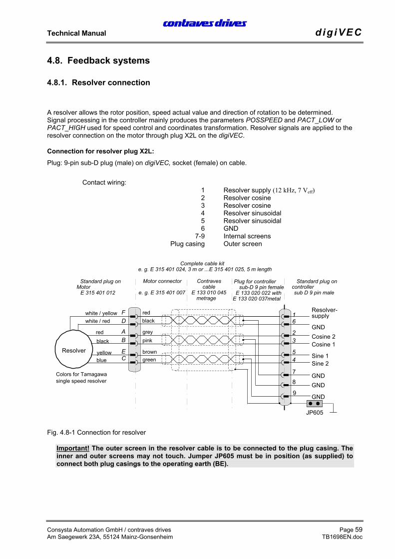
A resolver allows the rotor position, speed actual value and direction of rotation to be determined.Signal processing in the controller mainly produces the parameters POSSPEED and PACT_LOW orPACT_HIGH used for speed control and coordinates transformation. Resolver signals are applied to theresolver connection on the motor through plug X2L on the digiVEC.
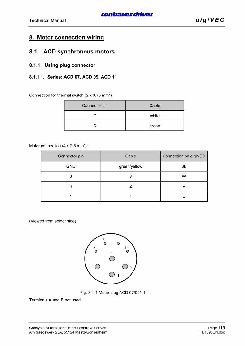
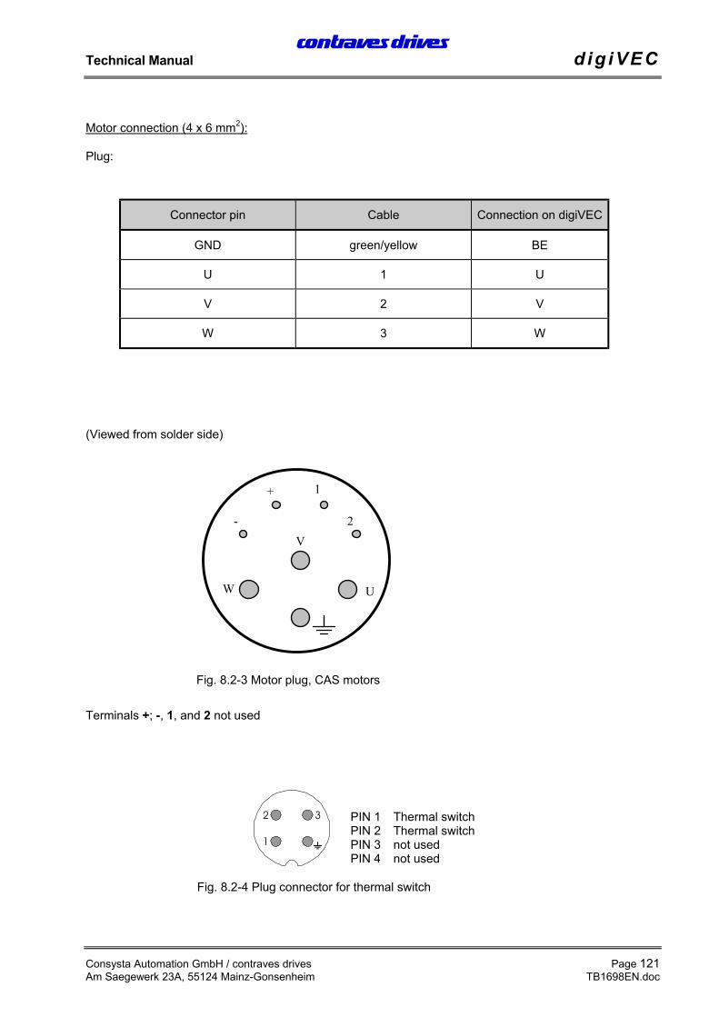
Connection for resolver plug X2L:Plug: 9-pin sub-D plug (male) on digiVEC, socket (female) on cable.
Important! The outer screen in the resolver cable is to be connected to the plug casing. Theinner and outer screens may not touch. Jumper JP605 must be in position (as supplied) toconnect both plug casings to the operating earth (BE).
16
23
54
FD
AB
EC
78
9
Resolver
white / yellowwhite / red
redblack
yellowblue
Colors for Tamagawasingle speed resolver
Standard plug oncontrollersub D 9 pin male
greypink
browngreen
redblack
Cosine 2Cosine 1
Sine 1Sine 2
Resolver-supply
GND
Plug for controllersub-D 9 pin female
E 133 020 022 withE 133 020 037metal
JP605
Contravescable
E 133 010 045metrage
Motor connector
e. g. E 315 401 007
Standard plug onMotor
E 315 401 012
GNDGND
GND
Complete cable kite. g. E 315 401 024, 3 m or ...E 315 401 025, 5 m length
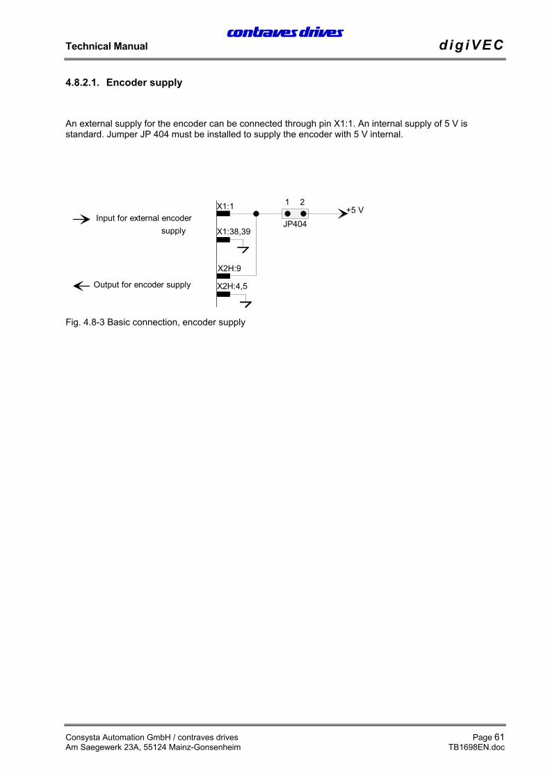
An external supply for the encoder can be connected through pin X1:1. An internal supply of 5 V isstandard. Jumper JP 404 must be installed to supply the encoder with 5 V internal.
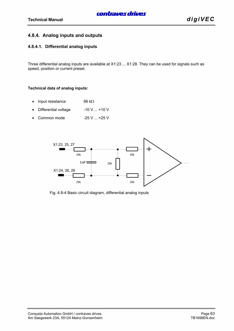
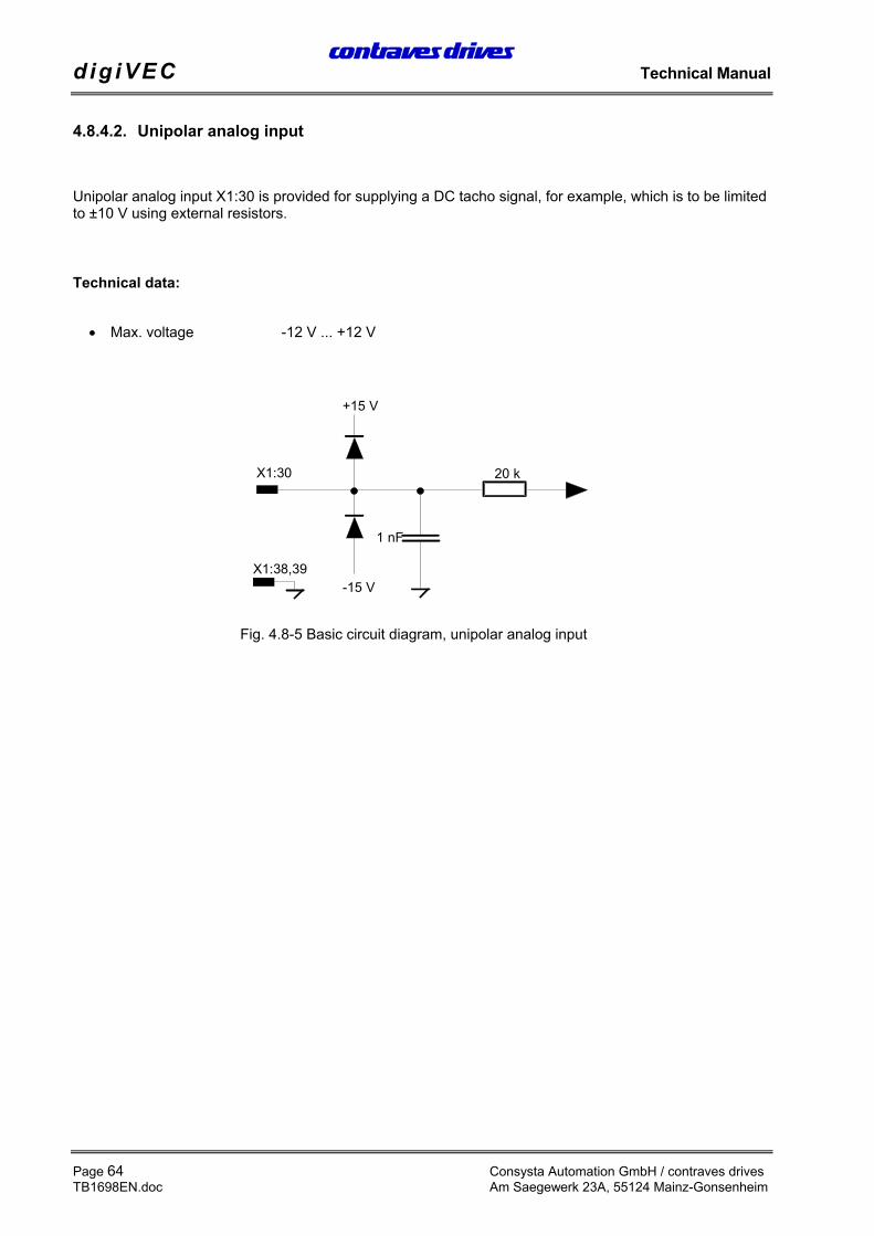
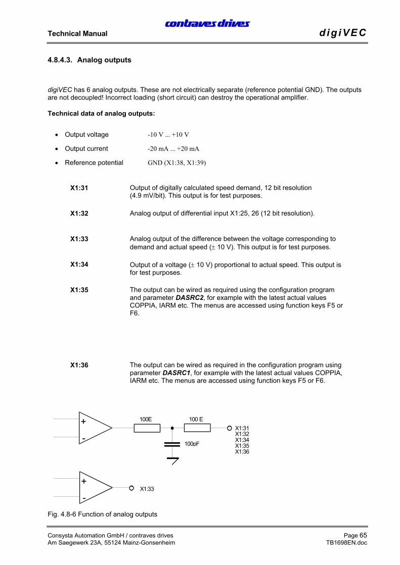
digiVEC has 6 analog outputs. These are not electrically separate (reference potential GND). The outputsare not decoupled! Incorrect loading (short circuit) can destroy the operational amplifier.
Technical data of analog outputs:
• Output voltage -10 V ... +10 V
• Output current -20 mA ... +20 mA
• Reference potential GND (X1:38, X1:39)
X1:31 Output of digitally calculated speed demand, 12 bit resolution(4.9 mV/bit). This output is for test purposes.
X1:32 Analog output of differential input X1:25, 26 (12 bit resolution).
X1:33 Analog output of the difference between the voltage corresponding todemand and actual speed (± 10 V). This output is for test purposes.
X1:34 Output of a voltage (± 10 V) proportional to actual speed. This output isfor test purposes.
X1:35 The output can be wired as required using the configuration programand parameter DASRC2, for example with the latest actual valuesCOPPIA, IARM etc. The menus are accessed using function keys F5 orF6.
X1:36 The output can be wired as required in the configuration program usingparameter DASRC1, for example with the latest actual values COPPIA,IARM etc. The menus are accessed using function keys F5 or F6.
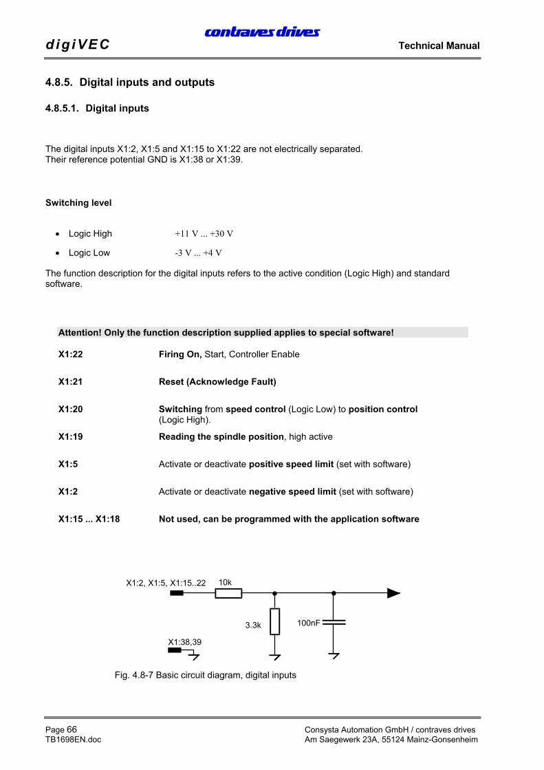
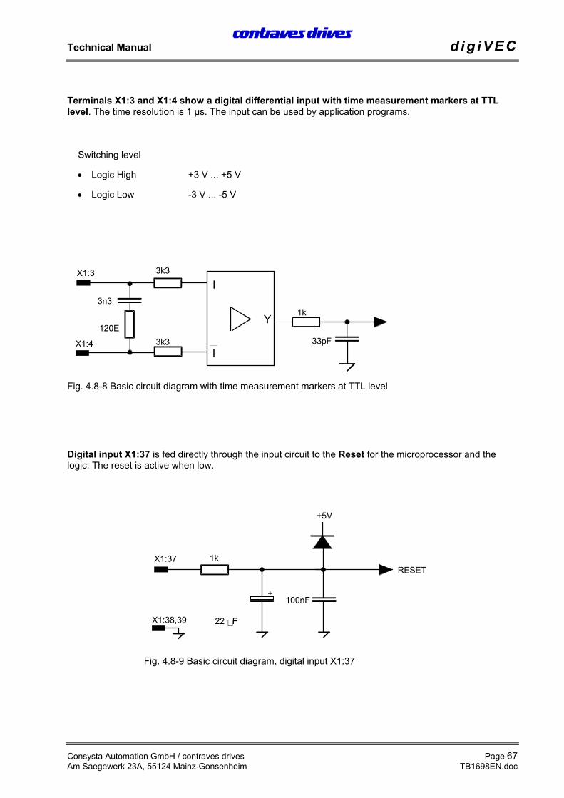
Terminals X1:3 and X1:4 show a digital differential input with time measurement markers at TTLlevel. The time resolution is 1 µs. The input can be used by application programs.
Switching level
• Logic High +3 V ... +5 V
• Logic Low -3 V ... -5 V
Digital input X1:37 is fed directly through the input circuit to the Reset for the microprocessor and thelogic. The reset is active when low.
3n3
3k3
I
I
Y
3k3
1k
33pF
X1:3
X1:4
120E
Fig. 4.8-8 Basic circuit diagram with time measurement markers at TTL level
X1:37
X1:38,39
100nF
1k
22 F
+
+5V
RESET
Fig. 4.8-9 Basic circuit diagram, digital input X1:37
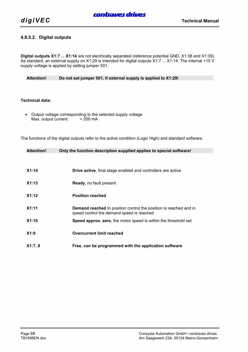
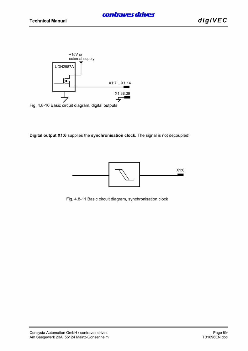
Digital outputs X1:7 ... X1:14 are not electrically separated (reference potential GND, X1:38 and X1:39).As standard, an external supply on X1:29 is intended for digital outputs X1:7 ... X1:14. The internal +15 Vsupply voltage is applied by setting jumper 501.
Attention! Do not set jumper 501, if external supply is applied to X1:29!
Technical data:
• Output voltage corresponding to the selected supply voltageMax. output current: < 200 mA
The functions of the digital outputs refer to the active condition (Logic High) and standard software.
Attention! Only the function description supplied applies to special software!
X1:14 Drive active, final stage enabled and controllers are active
X1:13 Ready, no fault present
X1:12 Position reached
X1:11 Demand reached In position control the position is reached and inspeed control the demand speed is reached
X1:10 Speed approx. zero, the motor speed is within the threshold set
X1:9 Overcurrent limit reached
X1:7, 8 Free, can be programmed with the application software
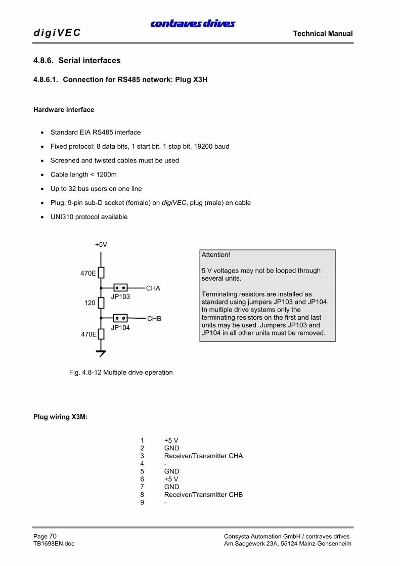
5 V voltages may not be looped throughseveral units.
Terminating resistors are installed asstandard using jumpers JP103 and JP104.In multiple drive systems only theterminating resistors on the first and lastunits may be used. Jumpers JP103 andJP104 in all other units must be removed.
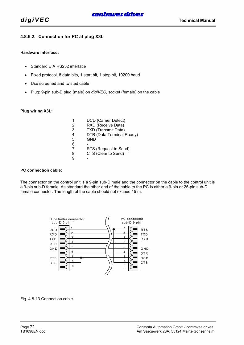
The connector on the control unit is a 9-pin sub-D male and the connector on the cable to the control unit isa 9-pin sub-D female. As standard the other end of the cable to the PC is either a 9-pin or 25-pin sub-Dfemale connector. The length of the cable should not exceed 15 m.
The following sections give step-by-step instructions for commissioning the digiVEC and the motor used.
Please note: The user should follow the procedure in the sequence stated, to avoid faults orerrors. Incorrect action during commissioning may damage the system (e.g. uncontrolledmotor acceleration) If these instructions are not observed Contraves Antriebstechnik GmbHcan accept no liability whatsoever for loss or damage.
The following are provided to assist with commissioning:
• The digiVEC configuration program
• Status indicators on the digiVEC front panel
Other equipment such as a (recording) oscilloscope for recording speed, torque, current, etc., a voltmeterand LED indicators for digital outputs are useful but not essential.
Only parameters which can be adjusted or must be adapted are mentioned below. Adjustment of any otherparameters by the user is at his own risk (note the safety instructions!).
Start-up response
The external supply to the control electronics must first be switched on so that the processor can carry outits monitoring functions.
The DC bus voltage is generated when the mains voltage (3 x 400 Veff) is applied. If it exceeds the 400 Vlimit [DCLINK_NOM (approx. %):, 400 V corresponding to 100%], the intermediate relay closes after a 3second pause to allow the full charging current for the capacitor battery.At the same time the resolver supply is generated through automatic calibration (LED 5 and LED 7 flash)
The controller is ready [LED 6 (green) is on] when this process is completed. The ready message ispresent as a voltage signal at terminal X1:13.
If the DC bus voltage falls below 340 V the drive is blocked. It is disabled and the intermediate relay isopened. This response is saved in battery-backed RAM so that restarting without first resetting after thefault is not possible.
Switching on as normal (as described above) is possible as soon as the fault is acknowledged throughX1:21 (Reset). A reset is only possible when the controller is disabled.
Shutdown response during normal operation:
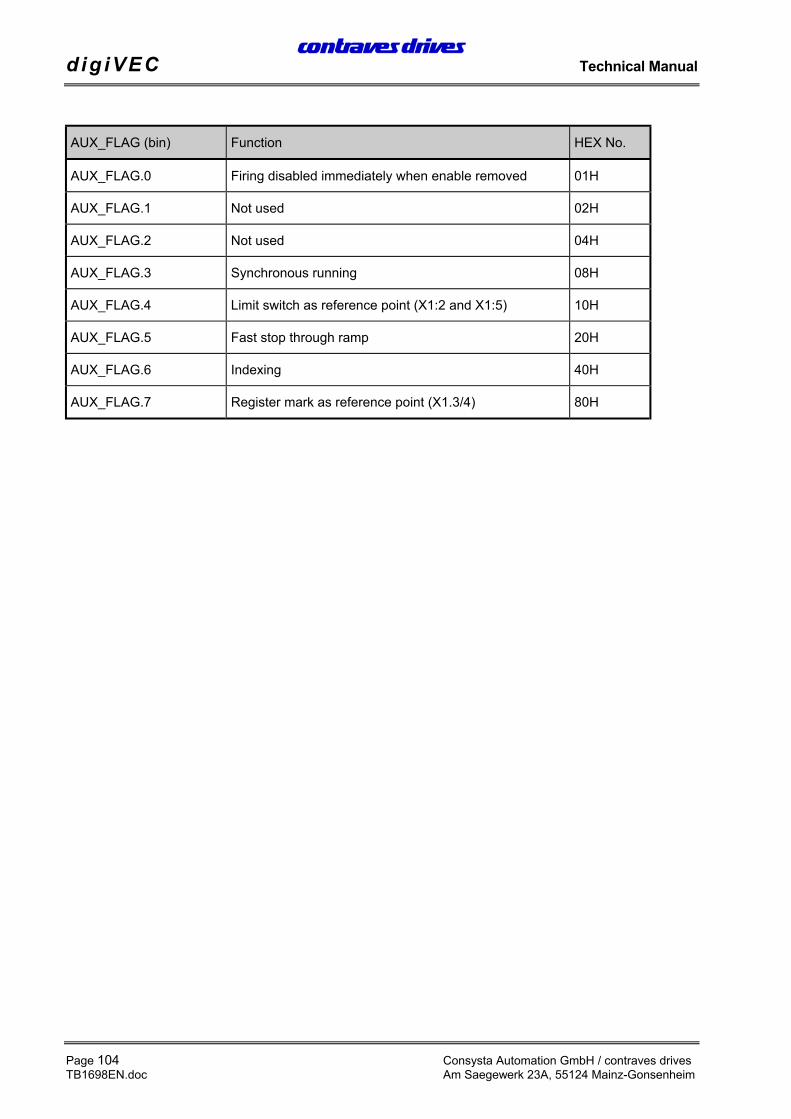
Firing is disabled when the motor reaches a standstill, to switch the unit off normally. If firing is switched offbefore the motor is at a standstill the inverter responds according to the activated AUX_FLAGs.
• AUX_FLAG.0: If firing is removed, the motor idles down
• AUX_FLAG.5: Fast stop through speed ramp setting (DECEL parameter)
If none of the two AUX_FLAGs is active the controller is braked using maximum braking current.
After “Firing off”, the mains voltage can be switched off and the controller opens the intermediate relay assoon as the DC bus voltage falls below 340 V. Normal restarting is as described above.
Connect the external (24 V) supply voltage according to section 4.6.
Connect the serial interface on the PC to terminal X3L on the digiVEC.
The digiVEC configuration program (the monitor program) is required for reading motor-specificparameters into the digiVEC controller. (A detailed description of the configuration program is given insection 4.1 digiVEC monitor program).
Call the program: start.bat Run program with English user interfaceorstartger.bat Run program with German user interface
When communication is possible the parameter values are displayed in the configuration program.
The descriptions below refer to the English user interface.
Load the hex files into the controller:The hex file supplied is always loaded into the RAM and FLASH memory before the controller can be putinto operation.
Load the file into the inverterRAM: Select Transfer menu
Click and confirm hexfile → ramSelect and confirm hex file.A loading routine will then start.
Load the file into the inverterFLASH memory: Select Transfer menu
Click and confirm initram program → flashA loading routine will start, the LEDs on the controller will flash.The hex file supplied is now in the Flash memory.
Note: In the configuration program it is possible to change between the individual memoryareas using function keys F4 - F6.
The BASE_SPEED parameter represents the rated speed according to the motor rating plate for a resolverwith a single pair of poles and is to be entered in the appropriate field.
5.2.3. Speed limit
The speed limits are generally set to 10% higher than motor rated speed:
It is not normally necessary to match the motor if the machine has been commissioned fully and correctly.However, if machine operation is disrupted during operation, manual adjustment as described below mayprovide a remedy.
5.3.1. Asynchronous motor
The parameters required for operating the motor must be set before calibration as described below (seesection 5.2)We recommend you note the new values for IGAIN, FLUX and ROTRES_NOM for later reference andkeep them with the commissioning documentation.
Proceed as follows for the adjustment:
1.) The motor must be able to rotate freely and be mechanically decoupled or atleast without any mechanical limiting.
The parameter below can only be edited in initram. Use function key F5 to switch from work RAM to initramat this point.
2.) IAMAX:= 1000 1000 corresponds to 1/3 of controller rated current ininternal units (range 0 - 3000).At IAMAX (%): Enter as a percentage value (an internal unitof 1000 corresponds to approx. 33% of controller ratedcurrent.IAMAX: = 3000 corresponds to 100% of controller ratedcurrent)
Further motor matching: Switch from initram to work RAM using function key F6
3.) ROTRES_NOM ≠ 0 e.g. ROTRES_NOM: = 1000 (basic setting)
4.) NMUX_VEL to be setto NREF
5.) NREF: = 0 Demand at 0
6.) CMDMUX: = CMDREF Selected setting preferably switching firing on/off and resetthrough configuration program instead of through digitalinputs.
Firing off, controller disabledFiring on, controller enabled orReset (fault acknowledgement)
8.) IAMUX:= NOUT Switch the demand through (for speed control)
9.) FLUX: Use the value calculated with the instructions below. Thevalue for magnetic field flux depends on the rated currentof the controller and motor used. The field current isapprox. 30% - 50% of motor rated current.Example: Motor rated current = 6 A → field current = 3 A(50%); controller rated current = 7 A (corresponding to3000 internal units) FLUX = 3000 x 3 A / 7A = 1280
10.) Automatic flux calibration:
10.1) CMDREF: = 01(Hex) Firing on, controller enable
10.2) NREF:= Increase until BASESPEED is reached. (POSSPEED =BASESPEED)
10.3) FLAG: = 20(Hex) This activates automatic flux calibration (FLUX). Allowthe motor to run at BASESPEED for approx. 10 s untilthe FLUX value no longer changes significantly.
10.4) FLAG: = 00(Hex) Reset the flag under section 10.3
11.1) CMDREF: = 01(Hex) Ignition on, controller enable
11.2) NREF: = Increase up to BASESPEED
11.3) IGAIN: Check the current with the oscilloscope at test point 3 or4 (see section 5.5.4 5.5.4). If distortion in the currentcharacteristics occurs, adjust IGAIN: to compensate forthe faults. IGAIN is to be set as high as possible.
11.4) NREF:= Reduce to 0 again in steps and set CMDREF: = 00(Hex)
12.3) NREF:= Adjust - BASESPEED and + BASESPEED in steps.Note the transition response in the speed characteristicon the oscilloscope (at speed output X1:34 on thedigiVEC). A linear transition of the shortest possibleduration is important. If the transition is not linear,ROTRES_NOM is too high. If the transition takes toolong, ROTRES_NOM is too low. Optimum basic setting:5 V. With this setting a step is made to -5 V on reversing.Reversing can be achieved by “tapping” the or keysonce. For this, position the cursor in front of the figure 5(_5.000). Note: Holding the key down for too long resultsin a double trigger (a doubling of speed).
12.4) NREF: = Reduce to 0 again in steps
12.5) CMDREF: = 00(Hex)
The following parameter can only be edited in the initram. Switch from work RAM to initram using functionkey F5 at this point.
12.6) IAMAX Reset according to application (max. 6000 internal units)
Switch from initram to work RAM using function key F6
This completes automatic self-calibration. All self-adjusting values are set and must now be saved in flashmemory:
13.) Setting ofPOLL_FLAG.0 andFAST_FLAG.3
Set POLL_FLAG.0 to deactivate automatic resolvercalibration.POLL_FLAG = 01HFAST_FLAG.3 must be set to compare the parameters inwork RAM with those in the flash memory after a systemreset:FAST_FLAG.3 = 04H
14.) Menu: Select Transfer and execute the following routines:work RAM parameters → initraminitram program → flash
15.) RESET A unit reset (system reset) is forced through jumper X1:37- X1:38 or by switching off the external 24 V DC or 18 VAC supply.
Attention! The motor must be mechanically decoupled and free to run.
The field current and rotor resistance for the synchronous motor are to be set to zero.Field excitation through permanent magnet is required.
1.) FLUX: = 0
2.) ROTRES_NOM: = 0
3.) SLIP_ANGLE: = 5350 If the number of motor pairs of poles pM = 3 and thenumber of resolver pairs of poles is pR = 1, this appliesonly the ACD series. Resolver adjustment is requiredwith other synchronous motors (see section 1 below).
4.) Current controllercalibration:
4.1 IGAIN: = 2500 (preset) Synchronous motors require a higher current gain thanasynchronous motors
4.2) CMDMUX:=CMDREF The setting used allows firing to be switched on and offand a reset through the configuration program insteadof through the digital inputs
4.3) CMDREF: = 01(Hex) Firing on, controller enable
4.4) NREF: = Increase to BASESPEED
4.5) IGAIN: IGAIN: Increase as long as the motor runs withoutvibrating
4.6) NREF: = Return to 0 again in steps and set CMDREF: = 00(Hex)
If the motor does not run without problems, adjust the resolver as described below:
I.) FLUX: = 0
II.) ROTRES_NOM: = 0
III.) IAMUX: = R0 Current controller input = 0
IV.) CMDMUX:=CMDREF The setting used allows firing to be switched on and offand a reset through the configuration program insteadof through the digital inputs
V.) CMDREF: = 01(Hex) Firing on, controller enable
Offset the “3-phase current balance” and simulate theload. Increase IU_OFFSET in steps of 100 up to +1000in total. Reduce IV_OFFSET in steps of 100 to -500 intotal. (Set the values in brackets to < ± 100 > using thecursor left or right keys. Then use cursor up or cursordown to increase or reduce the value accordingly).Attention: The motor will probably run and the shaft willalign itself in a specific position. If the motor oscillates,this oscillation is to be damped (possible by hand).Read off PACT_LOW (in internal unit). If the valuedisplayed exceeds 32767 it must be subtracted from65536 or added to the figure if it is more negative than -32768. The motor shaft must remain at a standstill.Record the value resulting and compare withSLIP_ANGLE.
If the difference between the two values exceeds ± 500 units:
VI.II) SLIP_ANGLE: = -(value) Negative value PACT_LOW
VI.III) CMDREF: = 00(Hex) Firing off forces a reset for the value IU_OFFSET andIV_OFFSET
VII.) IAMUX: = NOUT
Manual self-calibration is now complete. All self-adjusting values are set and must now be writteninto flash memory:
6.) Setting of POLL_FLAG.0and FAST_FLAG.3
Set POLL_FLAG.0 to deactivate automatic resolvercalibration:POLL_FLAG = 01HFAST_FLAG.3 must be set to compare the parametersin work RAM with those in the flash RAM after a systemreset: FAST_FLAG.3 = 04H
7.) Menu Select Transfer and execute the following routines:work RAM parameters → initraminitram program → flash
8.) RESET A unit reset (system reset) is forced through jumperX1:37-X1:38 or by switching off the external 24 V DC or18 V AC.
5.3.3.1. Calibrate NGAIN_NOM of speed controller (without applying demand)
Attention! This facility for setting NGAIN_NOM without applying a demand may only be usedwith a synchronous motor after the motor has been matched. (see section 5.3.2,Synchronous motor).
1.) NMUX_VEL (Addr): = NREF Set demand multiplexer to internal demand input.
2.) NREF (V): = 0 Demand = 0 (internal demand). The demandused for adjustment is set to 0. The motor is at astandstill.
3.) CMDMUX (Addr): =CMDREF Set command multiplexer to internal control viathe PC.
4.) CMDREF: = 01(Hex) Firing is switched on
6.) Increase NGAIN_NOM in smallsteps
(e.g. in steps of 10) until the motor vibrates.
7.) Reduce NGAIN_NOM in smallsteps
(e.g. in steps of 10) until the motor no longervibrates. (Hysteresis! The motor should be stableat this point).
5.3.3.2. Calibrate NGAIN_NOM of speed controller (with demand applied):
Attention! This facility for setting NGAIN_NOM with demand applied may only be used afterthe motor is matched. (See section 5.3.2, Synchronous motor).
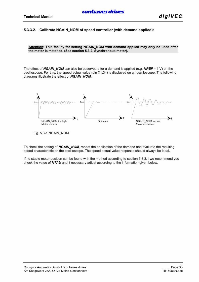
The effect of NGAIN_NOM can also be observed after a demand is applied (e.g. NREF = 1 V) on theoscilloscope. For this, the speed actual value (pin X1:34) is displayed on an oscilloscope. The followingdiagrams illustrate the effect of NGAIN_NOM:
To check the setting of NGAIN_NOM, repeat the application of the demand and evaluate the resultingspeed characteristic on the oscilloscope. The speed actual value response should always be ideal.
If no stable motor position can be found with the method according to section 5.3.3.1 we recommend youcheck the value of NTAU and if necessary adjust according to the information given below.
5.3.4. Fine calibration of NTAU for speed controller
Normally the value of NTAU need not be adjusted.
However, if the setting of NGAIN_NOM according to section 5.3.3.1 or 5.3.3.2 creates problems so that nostable position can be found (the motor trips from vibrating to overshooting without passing through anoptimum position), the value of NTAU must be adjusted.
Adjust NTAU as the first step: (Minimum values depending on hybrid)
• NTAU: = 0 150 Hz hybrid (indicated by the 0.22 µF capacitor)
• NTAU: = 1 300 Hz hybrid (indicated by the 0.1 µF capacitor)
If this value still does not allow a stable position, NTAU must be set by hand, i.e. adjusted in stages.
Begin with a low value for NTAU and increase NTAU in steps. After each increase, the setting ofNGAIN_NOM must be adjusted again according to section 5.3.3.2. NTAU is increased until an optimummotor setting is found for NGAIN_NOM. (See Fig. 5.3-1 NGAIN_NOM)
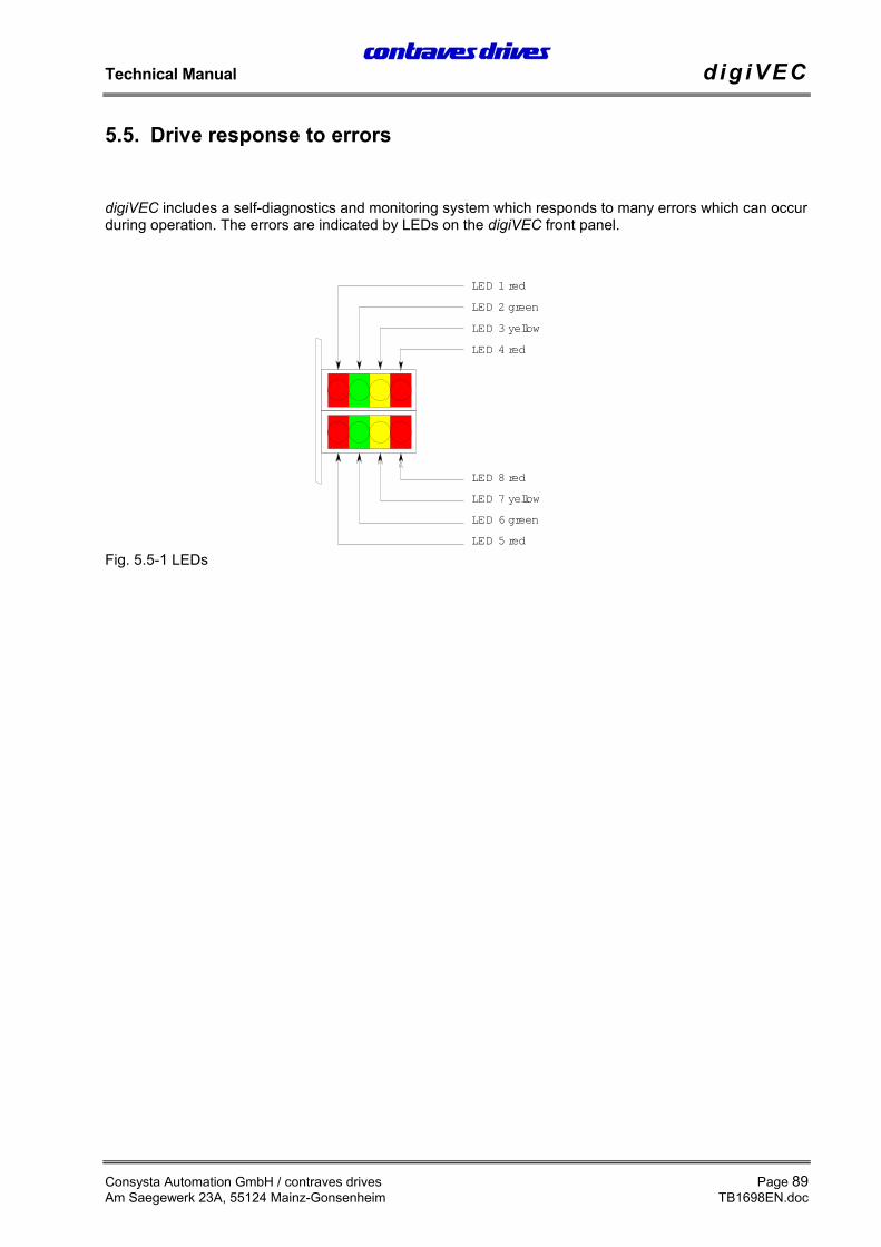
digiVEC includes a self-diagnostics and monitoring system which responds to many errors which can occurduring operation. The errors are indicated by LEDs on the digiVEC front panel.
The LEDs on the digiVEC front panel are numbered from 1 to 8. The indicators and their meanings aredescribed below.
LED 1 (red) has a double function depending on drive enable:
• With the drive enabled LED 1 lights if the energy flowing back from the motor is converted into heatby the braking resistor.
• If the drive is disabled LED 1 flashes when there is no communication through the serial interface.The number of ON phases between two longer OFF phases corresponds to the station address ofthe drive on the communications network (default station address MYSTAD (hex.) is 80H).
LED 2, 3 and 4 indicate errors during operation.
If several errors occur simultaneously the first error to occur is displayed. This error is retained until a resetis made. A reset is made either by making digital input X1:21 (Reset, fault acknowledgement) andsimultaneously breaking digital input X1:22 (Controller enable) with the motor at a standstill, through ajumper between terminals X1:37 and X1:38/39 (System reset) or by switching the external controllersupply voltage off and on again.
After a reset the drive is in the “Ready” condition if the error was corrected. Otherwise the drive is “Notready” (see LEDs 5 and 6).
LED 3 (yellow) on I x t limit reached. Overcurrent in power semiconductor (short circuit). Toorapid heat build-up in power semiconductor (overcurrent lasting severalseconds).. Heatsink overtemperature (continuous operation).
LED 4 (red) on Undervoltage
LED 5 and 6 Indicate the operating status of the drive.
LED 5 (red) on Drive enabled
LED 6 (green) on Drive ready
LED 7 (yellow) On if the motor is at a standstill
LED 8 (red) On if the drive has reached the torque limit and therefore regulation is nolonger guaranteed. Torque limit is determined by parameter IAMAX.
LED 1, 4, 5 and 8 On if the supply voltage for DAM card and fan is too low.
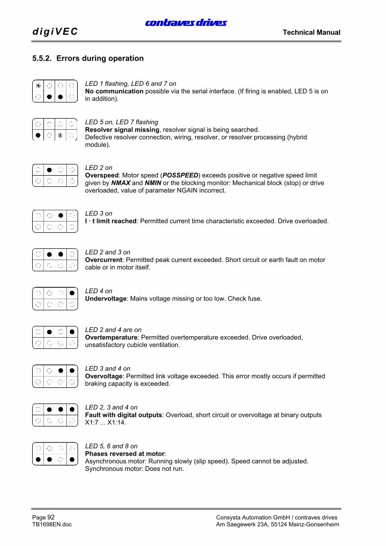
LED 1 flashing, LED 6 and 7 onNo communication possible via the serial interface. (If firing is enabled, LED 5 is onin addition).
LED 5 on, LED 7 flashingResolver signal missing, resolver signal is being searched.Defective resolver connection, wiring, resolver, or resolver processing (hybridmodule).
LED 2 onOverspeed: Motor speed (POSSPEED) exceeds positive or negative speed limitgiven by NMAX and NMIN or the blocking monitor: Mechanical block (stop) or driveoverloaded, value of parameter NGAIN incorrect.
LED 3 onI t limit reached: Permitted current time characteristic exceeded. Drive overloaded.
LED 2 and 3 onOvercurrent: Permitted peak current exceeded. Short circuit or earth fault on motorcable or in motor itself.
LED 4 onUndervoltage: Mains voltage missing or too low. Check fuse.
LED 2 and 4 are onOvertemperature: Permitted overtemperature exceeded. Drive overloaded,unsatisfactory cubicle ventilation.
LED 3 and 4 onOvervoltage: Permitted link voltage exceeded. This error mostly occurs if permittedbraking capacity is exceeded.
LED 2, 3 and 4 onFault with digital outputs: Overload, short circuit or overvoltage at binary outputsX1:7 ... X1:14.
LED 5, 6 and 8 onPhases reversed at motor:Asynchronous motor: Running slowly (slip speed). Speed cannot be adjusted.Synchronous motor: Does not run.
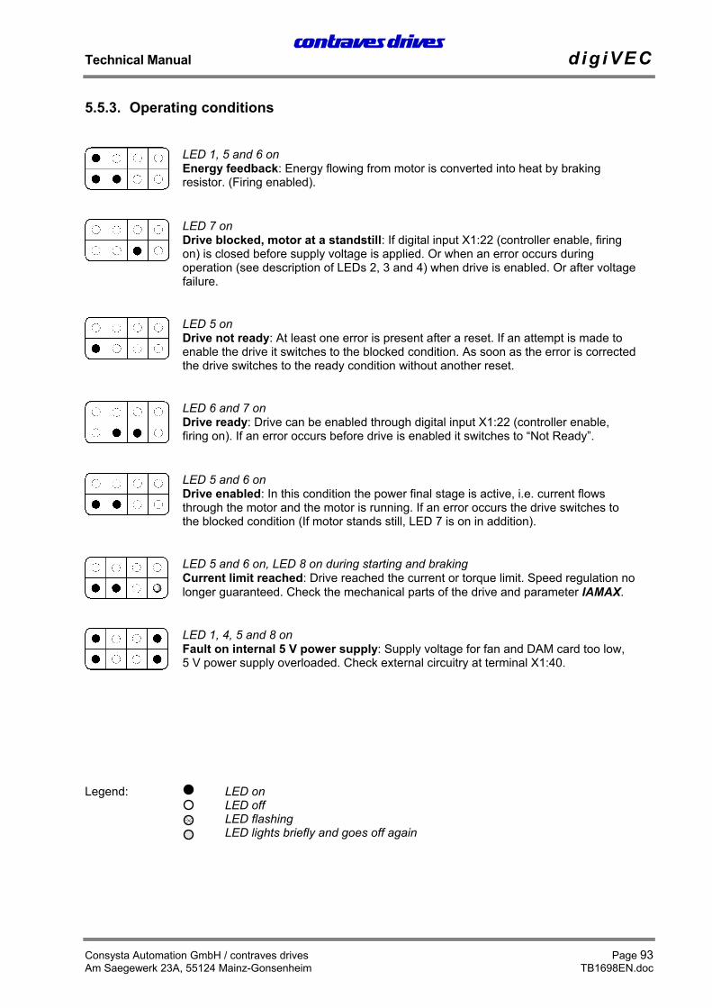
LED 1, 5 and 6 onEnergy feedback: Energy flowing from motor is converted into heat by brakingresistor. (Firing enabled).
LED 7 onDrive blocked, motor at a standstill: If digital input X1:22 (controller enable, firingon) is closed before supply voltage is applied. Or when an error occurs duringoperation (see description of LEDs 2, 3 and 4) when drive is enabled. Or after voltagefailure.
LED 5 onDrive not ready: At least one error is present after a reset. If an attempt is made toenable the drive it switches to the blocked condition. As soon as the error is correctedthe drive switches to the ready condition without another reset.
LED 6 and 7 onDrive ready: Drive can be enabled through digital input X1:22 (controller enable,firing on). If an error occurs before drive is enabled it switches to “Not Ready”.
LED 5 and 6 onDrive enabled: In this condition the power final stage is active, i.e. current flowsthrough the motor and the motor is running. If an error occurs the drive switches tothe blocked condition (If motor stands still, LED 7 is on in addition).
LED 5 and 6 on, LED 8 on during starting and brakingCurrent limit reached: Drive reached the current or torque limit. Speed regulation nolonger guaranteed. Check the mechanical parts of the drive and parameter IAMAX.
LED 1, 4, 5 and 8 onFault on internal 5 V power supply: Supply voltage for fan and DAM card too low,5 V power supply overloaded. Check external circuitry at terminal X1:40.
Legend: LED onLED offLED flashingLED lights briefly and goes off again
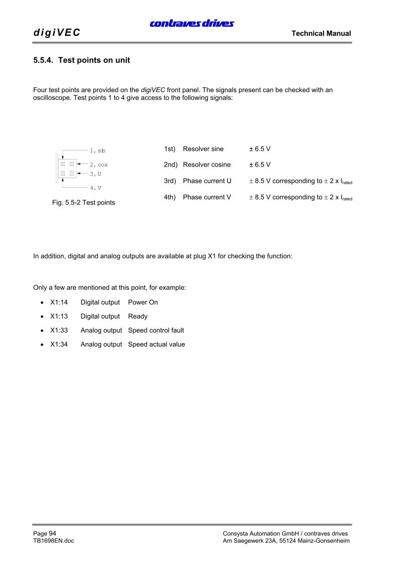
Four test points are provided on the digiVEC front panel. The signals present can be checked with anoscilloscope. Test points 1 to 4 give access to the following signals:
1st) Resolver sine ± 6.5 V
2nd) Resolver cosine ± 6.5 V
3rd) Phase current U ± 8.5 V corresponding to ± 2 x Irated
4th) Phase current V ± 8.5 V corresponding to ± 2 x Irated
In addition, digital and analog outputs are available at plug X1 for checking the function:
Only a few are mentioned at this point, for example:
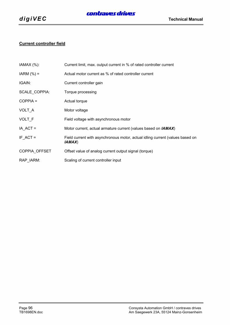
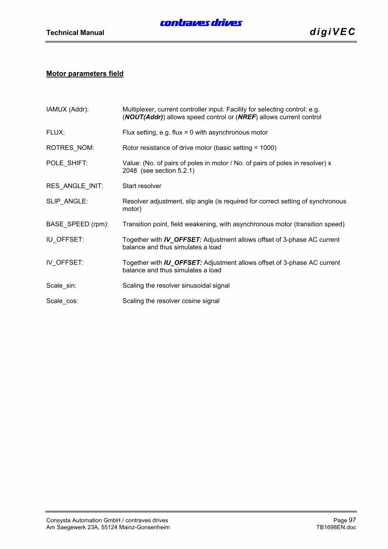
IAMUX (Addr): Multiplexer, current controller input. Facility for selecting control: e.g.(NOUT(Addr)) allows speed control or (NREF) allows current control
FLUX: Flux setting, e.g. flux = 0 with asynchronous motor
ROTRES_NOM: Rotor resistance of drive motor (basic setting = 1000)
POLE_SHIFT: Value: (No. of pairs of poles in motor / No. of pairs of poles in resolver) x2048 (see section 5.2.1)
RES_ANGLE_INIT: Start resolver
SLIP_ANGLE: Resolver adjustment, slip angle (is required for correct setting of synchronousmotor)
BASE_SPEED (rpm): Transition point, field weakening, with asynchronous motor (transition speed)
IU_OFFSET: Together with IV_OFFSET: Adjustment allows offset of 3-phase AC currentbalance and thus simulates a load
IV_OFFSET: Together with IU_OFFSET: Adjustment allows offset of 3-phase AC currentbalance and thus simulates a load
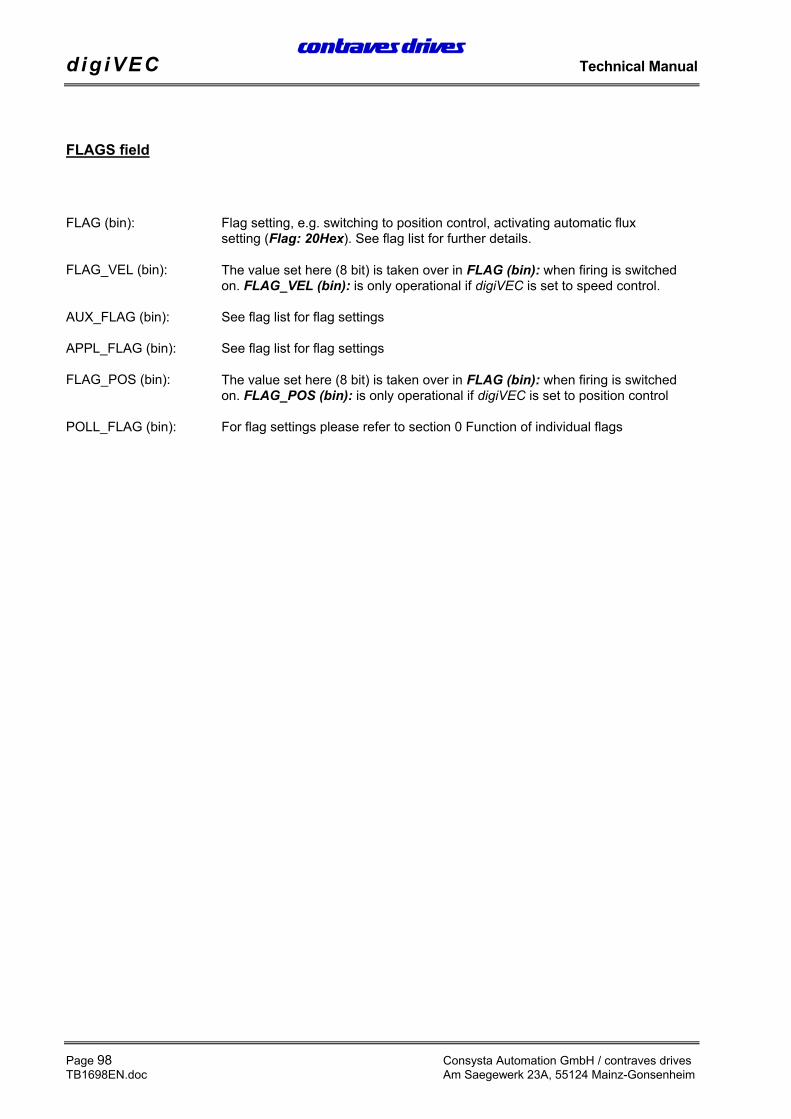
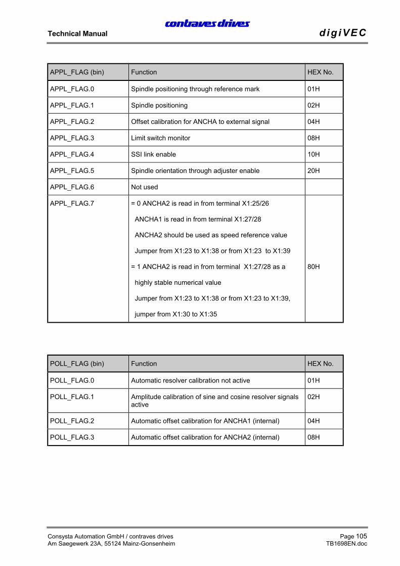
FLAG (bin): Flag setting, e.g. switching to position control, activating automatic fluxsetting (Flag: 20Hex). See flag list for further details.
FLAG_VEL (bin): The value set here (8 bit) is taken over in FLAG (bin): when firing is switchedon. FLAG_VEL (bin): is only operational if digiVEC is set to speed control.
AUX_FLAG (bin): See flag list for flag settings
APPL_FLAG (bin): See flag list for flag settings
FLAG_POS (bin): The value set here (8 bit) is taken over in FLAG (bin): when firing is switchedon. FLAG_POS (bin): is only operational if digiVEC is set to position control
POLL_FLAG (bin): For flag settings please refer to section 0 Function of individual flags
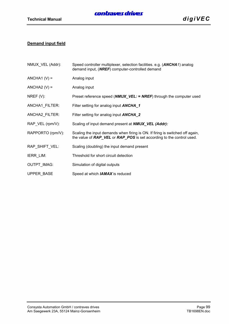
NREF (V): Preset reference speed (NMUX_VEL: = NREF) through the computer used
ANCHA1_FILTER: Filter setting for analog input ANCHA_1
ANCHA2_FILTER: Filter setting for analog input ANCHA_2
RAP_VEL (rpm/V): Scaling of input demand present at NMUX_VEL (Addr):
RAPPORTO (rpm/V): Scaling the input demands when firing is ON. If firing is switched off again,the value of RAP_VEL or RAP_POS is set according to the control used.
RAP_SHIFT_VEL: Scaling (doubling) the input demand present
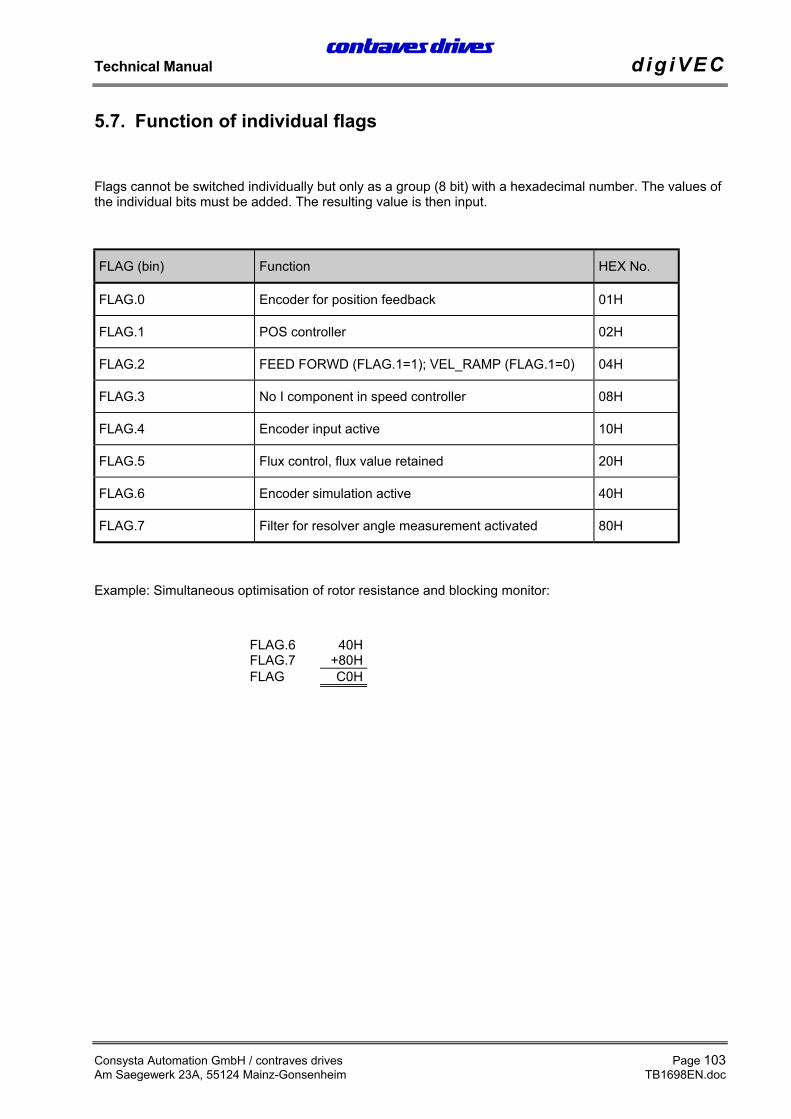
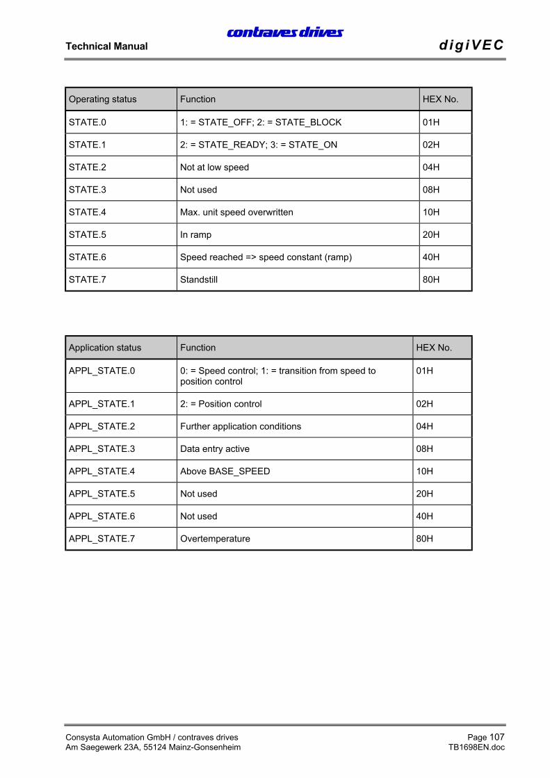
Flags cannot be switched individually but only as a group (8 bit) with a hexadecimal number. The values ofthe individual bits must be added. The resulting value is then input.
Screening and interference suppression.................49Fuses for electronic circuits ...................................58Analog outputs .......................................................65Analog inputs and outputs .....................................63Connection for PC .................................................72Asynchronous motor..............................................79Shutdown response ................................................74
B
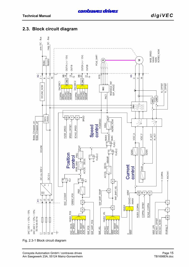
Frame size ..............................................................35User interface .........................................................43Intended use ...........................................................32Faults during operation ..........................................92Operating parameters .............................................95Operating conditions..............................................93Reference potential ................................................68Block circuit diagram.............................................15Braking resistors ....................................................56
D
Continuous braking capacity..................................56Differential analog inputs ......................................63Digital outputs........................................................68Digital inputs and outputs ......................................66Digital inputs..........................................................66Speed limiter ..........................................................77Speed control .........................................................25Speed controller ...............................................84; 86Calibrate speed controller ......................................843-phase bridge rectifier ..........................................18
E
EU Declaration of Conformity 96..........................37Input test ................................................................36Switching on ..........................................................36Start-up response....................................................73Setting motor parameters .......................................76EMC Guidelines.....................................................34Encoder ..................................................................19Encoder connection................................................60Encoder simulation ................................................31Encoder supply ......................................................61External supply voltage..........................................57
F
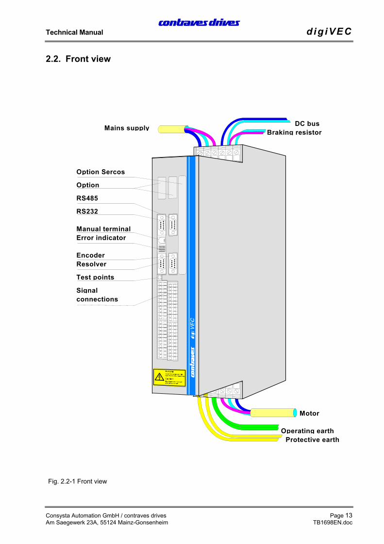
Fault .......................................................................89Field excitation.......................................................82Field weakening .....................................................33Humidity class .......................................................33Front view ..............................................................13Function of individual flags .................................103Function of LEDs...................................................90
G
Dangers.............................................................. 9; 32Unit description ..................................................... 17Unit data ................................................................ 35
H
Hardware interface ................................................ 70Help system ........................................................... 45Ancillary equipment .............................................. 73
Switching level ................................................ 66; 67Switchgear cubicle mounting ................................ 50Interfaces ............................................................... 57Protection class...................................................... 33Serial interfaces ..................................................... 70Safety and application instructions.......................... 2Safety conditions ..................................................... 9Fuses...................................................................... 58Signal leads ........................................................... 55Application of demands......................................... 85Scaling demands.................................................... 87Demand preset for position controller ................... 27Special function of position control ...................... 27Voltage link ........................................................... 18Memory areas ........................................................ 30Faults ..................................................................... 34Current control ...................................................... 25Synchronisation clock ........................................... 69Synchronous motor................................................ 82System reset..................................................... 30; 81
T
Switching frequency ..............................................33Teach in procedure.................................................28Technical data ........................................................33Test points ..............................................................94
U
Ambient conditions ................................................34Ambient temperature..............................................33Conversion of internal units...................................25Unipolar analog output ..........................................64
V
Connection cable to PC..........................................72Wiring ....................................................................47Power loss ..............................................................34Regulations ........................................................9; 34
W
AC voltage .............................................................57
Z
Supply cable cross-section ...............................52; 53Ancillary equipment...............................................33Optional equipment................................................12Link circuit.............................................................33Link voltage ...........................................................56