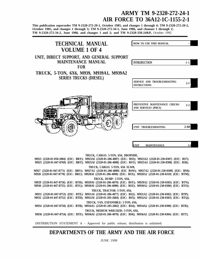
ARMY TM 9-2320-272-24-1 AIR FORCE TO 36A12-1C-1155-2-1 This publication supersedes TM 9-2320-272-20-1, October 1985, and changes 1 through 4; TM 9-2320-272-20-2, October 1985, and changes 1 through 3; TM 9-2320-272-34-1, June 1986, and chanaes 1 through 2; TM 9-2320-272-34-2, June 1986, and changes 1 and 2; and TM 9-2320-358-24&P, October 1992 TECHNICAL MANUAL VOLUME 1 OF 4 UNIT, DIRECT SUPPORT, AND GENERAL SUPPORT MAINTENANCE MANUAL FOR TRUCK, 5-TON, 6X6, M939, M939A1, M939A2 SERIES TRUCKS (DIESEL) HOW TO USE THIS MANUAL V INTRODUCTION l-l SERVICE AND TROUBLESHOOTING INSTRUCTIONS 2-l PREVENTlVE MAINTENANCE CHECKS AND SERVICES (PMCS) 2-2 UNIT TROUBLESHOOTING 2-60 UNIT MAINTENANCE 3-1 TRUCK, CARGO: 5-TON, 6X6, DROPSIDE, M923 (2320-01-050-2084) (EIC: BRY); M923Al (2320-01-206-4087) (EIC: BSS); M923A2 (2320-01-230-0307) (EIC: BS7); M925 (2320-01-047-8769) (EIC: BRT); M925Al (2320-01-206-4088) (EIC: BST); M925A2 (2320-01-230-0308) (EIC: B58); TRUCK, CARGO: 5-TON, 6X6 XLWB, M927 (2320-01-047-8771) (EIC: BRV); M927A1 (2320-01-206-4089) (EIC BSW); M927A2 (2320-01-230-0309) (EIC: BS9); M928 (2320-01-047-8770) (EIC: BRU); M928Al (2320-01-206-4090) (EIC: BSX); M928A2 (2320-01-230-0310) (EIC: BTM); TRUCK, DUMP: 5-TON, 6X6, M929 (2320-01-047-8756) (EIC: BTH); M929Al (2320-01-206-4079) (EIC: BSY); M929A2 (2320-01-230-0305) (EIC: BTN); M930 (2320-01-047-8755) (EIC: BTG); M930Al (2320-01-206-4080) (EIC: BSZ); M930A2 (2320-01-230-0306) (EIC: BTO); TRUCK, TRACTOR: 5-TON, 6X6, M931 (2320-01-047-8753) (EIC: BTE); M931Al (2320-01-206-4077) (EIC: BS2); M931A2 (2320-01-230-0302) (EIC: BTP); M932 (2320-01-047-8752) (EIC: BTD); M932Al (2320-01-205-2684) (EIC: BS5); M932A2 (2320-01-230-0303) (EIC: BTQ); TRUCK, VAN, EXPANSIBLE: 5-TON, 6X6, M934 (2320-01-047-8750) (EIC: BTB); M934A1 (2320-01-205-2682) (EIC: BS4); M934A2 (2320-01-230-0300) (EIC: BTR); TRUCK, MEDIUM WRECKER: 5-TON, 6X6, M936 (2320-01-047-8754) (EIC: BTF); M936Al (2320-01-206-4078) (EIC: BS6); M936A2 (2320-01-230-0304) (EIC: BTT). DISTRIBUTION STATEMENT A - Approved for public release; distribution is unlimited. DEPARTMENTS OF THE ARMY AND THE AIR FORCE JUNE 1998
Transcript
ARMY TM 9-2320-272-24-1AIR FORCE TO 36A12-1C-1155-2-1
This publication supersedes TM 9-2320-272-20-1, October 1985, and changes 1 through 4; TM 9-2320-272-20-2,October 1985, and changes 1 through 3; TM 9-2320-272-34-1, June 1986, and chanaes 1 through 2;TM 9-2320-272-34-2, June 1986, and changes 1 and 2; and TM 9-2320-358-24&P, October 1992
TECHNICAL MANUALVOLUME 1 OF 4
UNIT, DIRECT SUPPORT, AND GENERAL SUPPORTMAINTENANCE MANUAL
You can help improve this manual. If you find any mistakes or if you know of a way to improve theprocedures, please let us know. Mail your letter or DA Form 2028 (Recommended Changes to Publicationsand Blank Forms), or DA Form 2028-2 located in back of this manual, directly to: Director, Armament andChemical Acquisition and Logistics Activity, ATTN: AMSTA-AC-NML, Rock Island, IL 61299-7630. A replywill be furnished to you. You may also provide DA Form 2028-2 information via datafax or e-mail:
E-mail:am&[email protected]: DSN 783-0726 or commercial (309) 782-0726
DISTRIBUTION STATEMENT A - Approved for public release; distribution is unlimited.
i
TM 9-2320-272-24-1
*This publication supersedes TM 9-2320-272-20-1,24 October 1985, and changes 1 through 4; TM 9-2320-272-20-2,25October 1985, and changes 1 through 3; TM 9-2320-272-34-1, 10 June 1986, and changes 1 through 2; TM 9-2320-272-34-2,10 June 1986, and changes 1 and 2; and TM 9-2320-358-24&P, 21 October 1992.This publication is published in four volumes. TM 9-2320-272-24-1 contains chapters 1,2, and 3 (throughsection IX). TM 9-2320-272-24-2 contains chapters 3 (sections X through XVI) and 4 (sections I through III).TM 9-2320-272-24-3 contains chapter 4 (sections IV through XVI). TM 9-2320-272-24-4 contains chapters 5 and6 and appendices A through H. Volume 1 contains a table of contents for the entire manual. Volumes 1,2, and 3contain an alphabetical index covering tasks found in their respective volume. Volume 4 contains analphabetical index covering all tasks found in the entire manual.
Spend some time looking through this manual. You’ll find that it has a new look, different than mostTMs you’ve been using, including its predecessors, TM 9-2320-272-20-1, TM 9-2320-272-20-2,TM 9-2320-272-34-1, TM 9-2320-272-34-2, and TM 9-2320-358-24&P.
New features added to improve the convenience of this manual and increase your efficiency are:
a. Accessing Information - These include physical entry features such as the bleed-to-edgeindicators on the cover and edge of the manual. Extensive troubleshooting guides for specificsystems lead directly to step-by-step directions for problem solving and maintenance tasks.
b. Illustrations -A variety of methods are used to make locating and fixing components much easier.Locator illustrations with keyed text, exploded views, and cut-away diagrams make the informationin this manual easier to understand and follow.
c. Commonality - Only items that are unique to a specific series or vehicle will be given a separateprocedure. When only minor differences occur, notes are added to tell you to alter the normalprocedure in one way or another to accommodate the differences.
d. Keying Text with Illustrations - Instructions/text are located together with illustrations of thespecific task you are performing. In most cases, the task steps and illustrations are located onfacing pages, with text on the left and illustrations on the right. Continue reading for an example ofmodular text and illustration layout,
HOW TO USE THIS MANUAL
Here’s an example of how to use your manual:
Task: The unit maintenance mechanic of an M939 series vehicle reports that the engine cranks but fails tostart.Troubleshooting steps:
1. Look at the cover of this manual. You’ll see subjects listed from top to bottom on the right-hand side.2. Look at the right edge of the manual. On some of the pages you’ll see black bars (edge indicators)
that are aligned with the subject bars on the cover. These are the locations of the subjects in themanual.
3. Look for UNIT TROUBLESHOOTING in the subject list on the cover,
4. Turn to the page with the edge indicator matching the subject bar for UNIT TROUBLESHOOTING.Page numbers are also listed next to the subject titles.
5. An edge indicator is placed on the first page of the UNIT TROUBLESHOOTING.NOTE
If the first page of a subject has an even-numbered page, it willappear on your left, but the edge indicator will still be on the page toyour right. So, if the information you are looking for does not start onthe page to your right, it will on the page to your left.
6. Look down the list until you find ENGINE. Beneath that heading you will find the symptoms notedby the maintenance mechanic: Engine cranks, fails to start.
7. Turn to the page indicated: page 2-9.8. On page 2-9, steps/test relating to resolving the malfunction of “Engine cranks, fails to start,” are:
Step 1. You inspect the fuel pump shutoff valve and find it is defective and must be replaced. Yousee para. 4-6 referenced.Step 2. The rest of the inspection shows no other cause for the problem.
9. Locate para. 4-5, and you will find the detailed procedure for removing the old fuel pump shutoffvalve and replacing it with a new one.
v
TM 9-2320-272-24-1
HOW TO USE THIS MANUAL (Contd)
NOTEBefore starting the maintenance task, look through the entireprocedure to familiarize yourself with it.
a. The entire procedure (4-5. FUEL PUMP SHUTOFF REPLACEMENT), according to the THISTASK COVERS header, includes: a. Removal and b. Installation.
b. The nine basic subheadings listed under INITIAL SETUP outline the task preconditions,materials, tools, manpower requirements, and general safety instructions. They are:
APPLICABLE MODELS: Any models that require that particular maintenance task.TEST EQUIPMENT: Test equipment needed to complete a task.
SPECIAL TOOLS : Those tools required to complete the task.MATERIALS/PARTS: All parts or materials required to complete the task.
PERSONNEL REQUIRED: The number and type of personnel needed to accomplish a task.NOTE
If you think you need more help to correctly or safely complete thetask (perhaps as a result of an unusual condition, etc.), alert yoursupervisor and ask for help.
REFERENCES(TM): Those manuals required to complete the task.
EQUIPMENT CONDITIQN Notes the conditions that must exist before starting the task.For (4-5. FUEL PUMP SHUTOFF REPLACEMENT), the hood must be raised and secured(TM 9-2320-272-10), and the left splash shield removed (TM 9-2320-272-10). SPECIAL ENVIROMENTAL CONDITIONS: Outlines specific environmental conditionsnecessary to perform the task. For example: Darken an area when adjusting headlightbeams.GENERAL SAFETY INSTRUCTIONS: Summarizes all safety warnings for themaintenance task.
c. A step-by-step maintenance procedure follows the INITIAL SETUP.
d. At the end of the procedure, FOLLOW-ON TASK(S) will list those additional task(s) that must beperformed to complete the procedure. The follow-on tasks for 4-5. FUEL PUMP SHUTOFFREPLACEMENT are: Start engine (TM 9-2320-272-10), check fuel pump shutoff valve for properoperation (TM 9-2320-272-101, install left. splash shield (TM 9-2320-272-10), and lower and securehood (TM 9-2320-272-10X
10. Refer to our example procedure, 4-5. FUEL PUMP SHUTOFF REPLACEMENT as we review thefollowing points:
a. Modular Text: Both pages of text and illustrations are to be used together. This manual wasdesigned so that the two pages are visible at once, making part identification and proceduresequence easy to follow.
b. Initial Setup: Outlines task conditions.c. Illustrations: An exploded view of the components removed from the vehicle shows part
locations, attachments, and spatial relationships.11. Refer to TM 9-2320-272-24P, Unit, Direct Support, and General Support Maintenance Repair Parts
and Special Tools List for Truck, 5-Ton, 6x6, M939, M939A1, M939A2 Series Trucks, whenrequisitioning parts and special tools for Unit, Direct Support, and General Support maintenance,
12. Your manual is easier to use once you understand its design. We hope it will encourage you to use itmore often.
vi
TM 9-2320-272-24-1
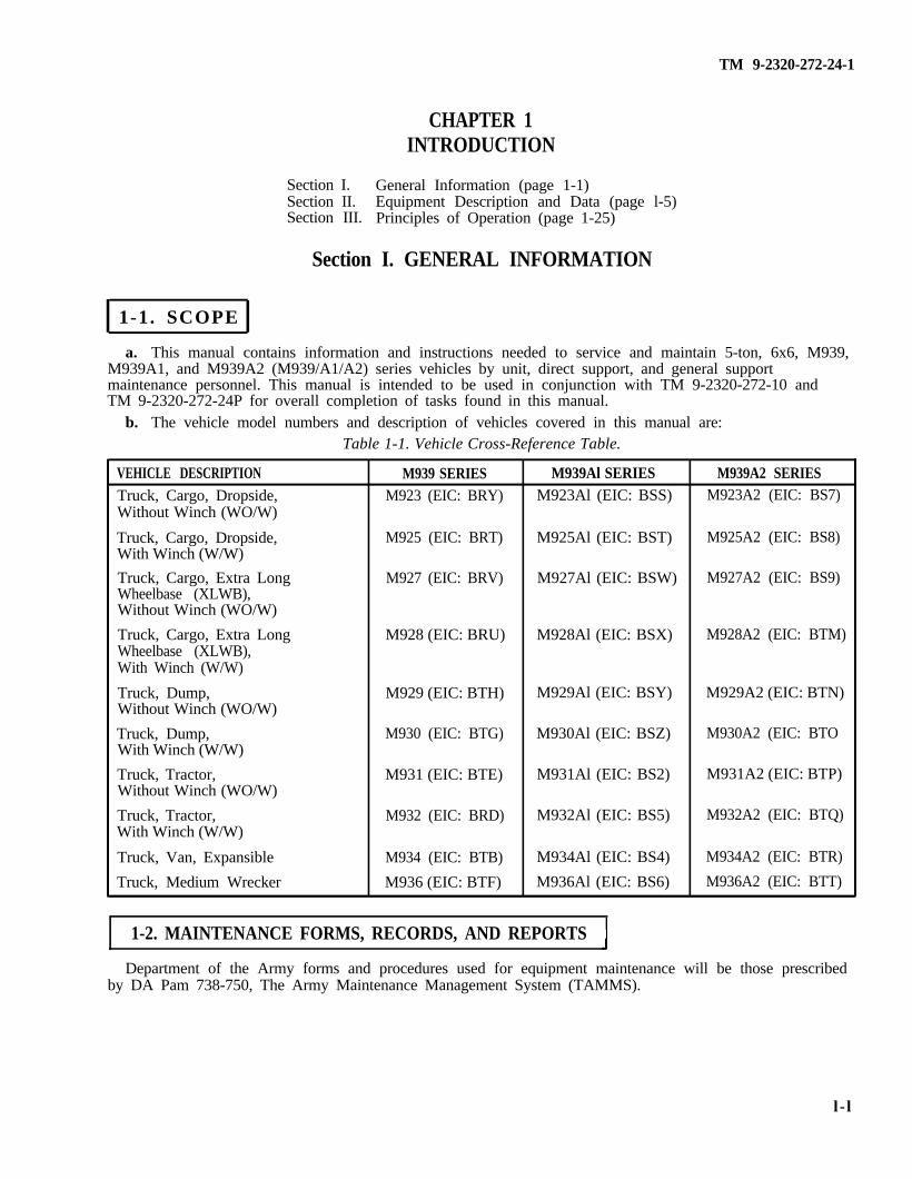
CHAPTER 1INTRODUCTION
Section I. General Information (page 1-1)Section II. Equipment Description and Data (page l-5)Section III. Principles of Operation (page 1-25)
Section I. GENERAL INFORMATION
1-1. SCOPE
a. This manual contains information and instructions needed to service and maintain 5-ton, 6x6, M939,M939A1, and M939A2 (M939/A1/A2) series vehicles by unit, direct support, and general supportmaintenance personnel. This manual is intended to be used in conjunction with TM 9-2320-272-10 andTM 9-2320-272-24P for overall completion of tasks found in this manual.
b. The vehicle model numbers and description of vehicles covered in this manual are:Table 1-1. Vehicle Cross-Reference Table.
VEHICLE DESCRIPTION
Truck, Cargo, Dropside,Without Winch (WO/W)
Truck, Cargo, Dropside,With Winch (W/W)
Truck, Cargo, Extra LongWheelbase (XLWB),Without Winch (WO/W)
Truck, Cargo, Extra LongWheelbase (XLWB),With Winch (W/W)
Department of the Army forms and procedures used for equipment maintenance will be those prescribedby DA Pam 738-750, The Army Maintenance Management System (TAMMS).
l - l
TM 9-2320-272-24-1
1-3. DESTRUCTION OF ARMY MATERIEL TO PREVENT ENEMY USE
Procedures for destruction of Army materiel to prevent enemy use can be found in TM 750-244-6.
1-4. PREPARATION FOR STORAGE OR SHIPMENT
Storage and shipment instructions are found in chapter 6. Additional information can be found inTM 740-90-1, Marking, Packing, and Shipment of Supplies and Equipment: General Packaging Instructionsfor Field Use.
l-5. OFFICIAL NOMENCLATURE
The nomenclature, names, and designations used in this manual are in accordance withMIL-HDBK-63038-2.
l-6. REPORTING EQUIPMENT IMPROVEMENT RECOMMENDATIONS (EIRs);REPORTING OF ERRORS AND RECOMMENDING IMPROVEMENTS
You can help improve this manual. If you find any mistakes or if you know of a way to improve theprocedures, please let us know. Mail your letter, DA Form 2028 (Recommended Changes to Publications andBlank Forms), or DA Form 2028-2 located in back of this manual direct to: Commander, U.S. Army Tank-automotive and Armaments Command, ATTN: AC-NML, Rock Island, IL 61299-7630. A reply will befurnished to you.
1-7. WARRANTY INFORMATION
The 5-ton, 6x6, M939/Al series vehicle Cummins engine (model NHC 250) and Allison transmission(model MT564CR) are warranted in accordance with TB 9-2300-295-15/21. The warranty starts on the datefound in block 23, DA Form 2408-9, in logbook. Report all defects in material or workmanship to yoursupervisor, who will take appropriate action.
1-8. ARMY PETROLEUM, OILS, AND LUBRICANTS (POL)
Proper disposal of hazardous waste material is vital to protecting the environment and providing a safework environment. Materials such as batteries, oils, and antifreeze must be disposed of in a safe andefficient manner.
The following references are provided as a means to ensure proper disposal methods are followed:Technical Guide No. 126 (from the U.S. Army Environmental Hygiene Agency)National Environmental Policy Act of 1969 (NEPA)
Clean Air Act (CAA)Resource Conservation and Recovery Act (RCRA)
Comprehensive Environmental Response, Compensation, and Liability ActEmergency Planning and Community Right to Know Act (EPCRA)Toxic Substances Control Act (TSCA)Occupational Health and Safety Act (OHSA)
The disposal of Army Petroleum, Oils, and Lubricants (POL) products are affected by some of theseregulations. State regulations may also be applicable to POL. If you are unsure of which legislation affectsyou, contact state or local agencies for regulations regarding proper disposal of Army POL.
l-2
TM 9-2320-272-24-1
1-9. USE OF METRIC SYSTEM
The equipment/system described herein contains metric common and special tools; therefore, metric unitsin addition to U.S. standard units will be used throughout this publication.
1-10. LIST OF ABBREVIATIONS
AOAP - Army Oil Analysis Programbx- boxCAGEC - Commercial and Government Entity Codecm - centimeterCTIS - Central Tire Inflation Systemcu-ft - cubic feetcu-yd - cubic yardcuM - cubic Meterea - eachft - feetGM - Grease, Automotive and ArtilleryGTW - Gross Towed Weightgal. - gallonin. inchkg- kilogramskm/h - kilometers per hourkm/L - kilometers per literkPa - kiloPascalL - literlb-ft - pound-feetlb - poundmax - maximummin - minimum
1-11. GLOSSARY
mm - millimetermpg - miles per gallonmph - miles per hourN•m - Newton meterNATO - North Atlantic Treaty OrganizationOZ - ouncepara. - paragraphPMCS - Preventive Maintenance Checks and
ServicesPOL - Petroleum, Oils, and Lubricantspsi - pounds per square inchpt - pintPTO - Power Takeoffqt - quartrpm - revolutions per minuteSEA - Standard, Engineering, and AutomotiveTMDE - Test, Measurement, and Diagnostic
EquipmentU/M - Unit of MeasureW/W - With WinchWO/W - Without WinchXLWB - Extra Long Wheelbase
APPROACH ANGLE - Angle between front tire and front bumperDEPARTURE ANGLE - Angle between rear tire and rear bumperFORDING - Crossing through water
GRADE - Steepness of terrainHYDRAULIC - Operated by oil pressure
OPERATOR - Driver of vehiclePAULIN - Canvas cover or tarpaulin (tarp)
SLAVING -Jump starting
1-3/( 1-4 blank)
TM 9-2320-272-24-1
Section II. EQUIPMENT DESCRIPTION AND DATA
l-l2. EQUIPMENT DESCRIPTION AND DATA INDEX
PARA.NO.
1-13.1-14.
1-15.
TITLE
Equipment Characteristics, Capabilities, and FeaturesLocation and Description of Major Components
Differences Between Models
PAGENO.
1-51-16l-20
1-16. Equipment Data1-17. Description of Data Plates
1-22l-24
1-13. EQUIPMENT CHARACTERISTICS, CAPABILITIES, AND FEATURES
a. The M939, M939A1, and M939A2 (M939/A1/A2) series of vehicles are varied in design andcapabilities. The M939 was a redesign and retrofit of the MS09 series of vehicles, providing enhancedcapabilities.
(1) The leading features of the M939 are:(a) Automatic transmission (Allison MT654)(b) Hydraulic-assisted power steering system(c) Complete airbrake system(d) Improved cooling system(e) Three-crewmember cab(f) Tilt hood
(2) Changes were incorporated into later production engines (after engine serial number 11246663)which provided for control of exhaust gas recirculation back to the air intake manifold and the use of top-stop injectors to make up a clean air configuration.
(3) The M939Al improved on the M939 by adding 14:00xR20 super-sized tires, increasing theminimum road clearance and approach and departure angle. This necessitated a modification to the sparetire rack and lifting device used on all series vehicles.
(4) The M939A2 incorporated a new engine (Cummins 6CTA8.3) and the Central Tire Inflation System(CTIS).
b. The M939/A1/A2 series vehicles can be distinguished from the M809 series by the following features:
(1) On the left side, the exhaust was moved behind the cab and tilted out so exhaust gases clear theside of the vehicle. Hood latches were installed on the sides of the hood near the mirrors. The battery boxwas incorporated into the companion seat to improve battery life in cold climates. A steering-assist cylinderwas installed between the right front frame rail and the right axle hub.
(2) From the front, the hood and fenders are an assembly which tilt forward for access to the enginecompartment. A tilt handle and locking device was installed to tilt and hold the hood in a secured openposition.
(3) The air filter was moved under the driver’s door and the intake stack was brought up behind thecab, even with the cab top.
1-5
TM 9-2320-272-24-1
1-13. EQUIPMENT CHARACTERISTICS, CAPABILITIES, AND FEATURES (Contd)
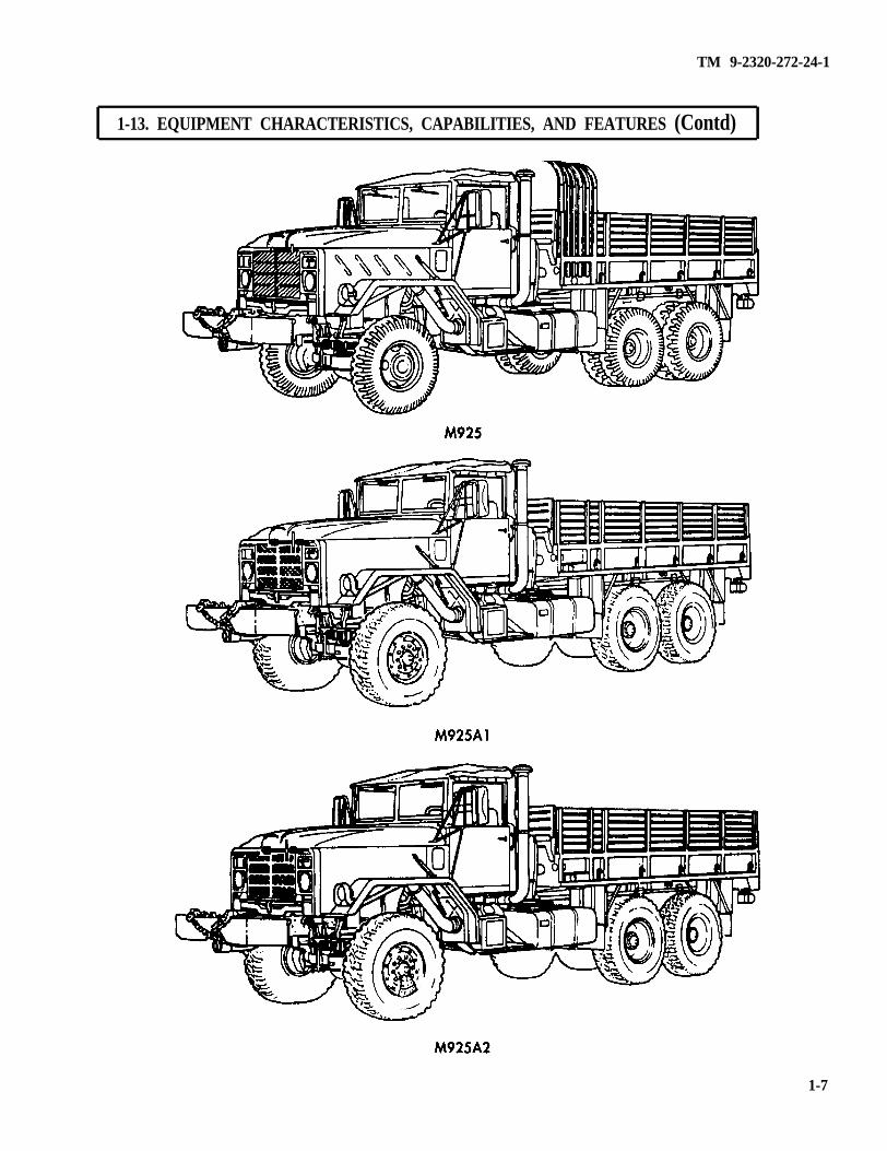
c. Cargo Trucks With Dropsides: M923/A1/A2 WO/W and M925/A1/A2 W/W.PURPOSE: These models are used to transport cargo and troops. The vehicles have a payload rating of
10,000 lbs (4,540 kg) and provide 550 cu-ft (15.4 CuM) of cargo space. Removable dropsides and tailgatepermit hauling of extra wide loads and easy access for unloading cargo. Troop seats, bows, and canvas arealso available. The M925/A1/A2 models have front winches and can be used for recovery operation. The bedof the M923A1/A2 and M925Al/A2 has been shifted back to facilitate a new lifting davit and spare tiremount. When the tire is mounted in its storage location on the M923A1/A2 and M925Al/A2, the top of thetire extends above the minimal reducible height and may need to be removed to obtain the necessarymeasurement.
1-6
TM 9-2320-272-24-1
1-13. EQUIPMENT CHARACTERISTICS, CAPABILITIES, AND FEATURES (Contd)
1-7
TM 9-2320-272-24-1
1-l3. EQUIPMENT CHARACTERISTICS, CAPABILITIES, AND FEATURES (Contd)
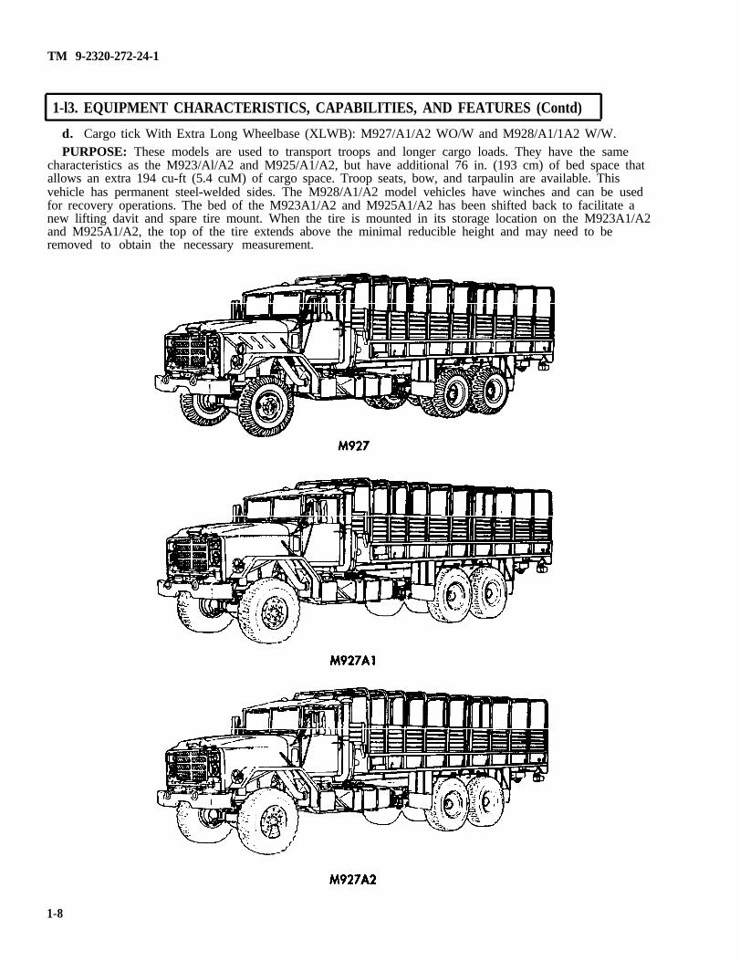
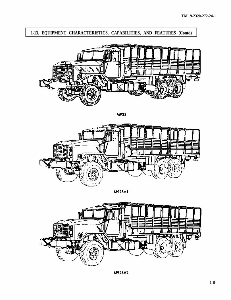
d. Cargo tick With Extra Long Wheelbase (XLWB): M927/A1/A2 WO/W and M928/A1/1A2 W/W.PURPOSE: These models are used to transport troops and longer cargo loads. They have the same
characteristics as the M923/Al/A2 and M925/A1/A2, but have additional 76 in. (193 cm) of bed space thatallows an extra 194 cu-ft (5.4 cuM) of cargo space. Troop seats, bow, and tarpaulin are available. Thisvehicle has permanent steel-welded sides. The M928/A1/A2 model vehicles have winches and can be usedfor recovery operations. The bed of the M923A1/A2 and M925A1/A2 has been shifted back to facilitate anew lifting davit and spare tire mount. When the tire is mounted in its storage location on the M923A1/A2and M925A1/A2, the top of the tire extends above the minimal reducible height and may need to beremoved to obtain the necessary measurement.
1-8
TM 9-2320-272-24-1
1-13. EQUIPMENT CHARACTERISTICS, CAPABILITIES, AND FEATURES (Contd)
1-9
TM 9-2320-272-24-1
1-13. EQUIPMENT CHARACTERISTICS, CAPABILITIES, AND FEATURES (Contd)
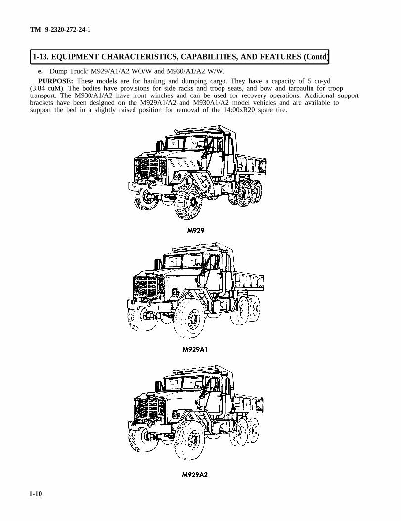
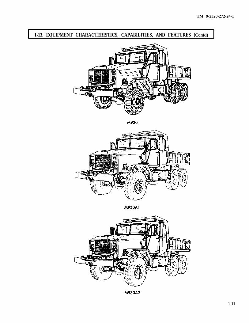
e. Dump Truck: M929/A1/A2 WO/W and M930/A1/A2 W/W.PURPOSE: These models are for hauling and dumping cargo. They have a capacity of 5 cu-yd
(3.84 cuM). The bodies have provisions for side racks and troop seats, and bow and tarpaulin for trooptransport. The M930/A1/A2 have front winches and can be used for recovery operations. Additional supportbrackets have been designed on the M929A1/A2 and M930A1/A2 model vehicles and are available tosupport the bed in a slightly raised position for removal of the 14:00xR20 spare tire.
1-10
TM 9-2320-272-24-1
1-13. EQUIPMENT CHARACTERISTICS, CAPABILITIES, AND FEATURES (Contd)
1-11
TM 9-2320-272-24-1
1-13. EQUIPMENT CHARACTERISTICS, CAPABILITIES, AND FEATURES (Contd)
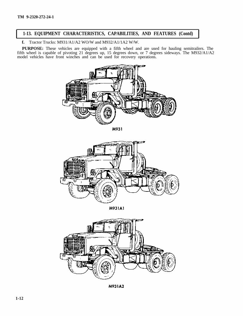
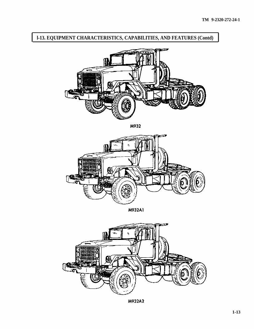
f. Tractor Trucks: M931/A1/A2 WO/W and M932/A1/1A2 W/W.
PURPOSE: These vehicles are equipped with a fifth wheel and are used for hauling semitrailers. Thefifth wheel is capable of pivoting 21 degrees up, 15 degrees down, or 7 degrees sideways. The M932/A1/A2model vehicles have front winches and can be used for recovery operations.
1-12
TM 9-2320-272-24-1
l-13. EQUIPMENT CHARACTERISTICS, CAPABILITIES, AND FEATURES (Contd)
1-13
TM 9-2320-272-24-1
1-13. EQUIPMENT CHARACTERISTICS, CAPABILITIES, AND FEATURES (Contd)
g. Expansible Vans: M934/A1/A2.PURPOSE: These vehicles are used for electronics, maintenance, supply, power, and base station
operation. The van body can be expanded when set up in a stationary mode of operation; when missionrequires more mobile-type operation, the body is left in the retracted position.
1-14
TM 9-2320-272-24-l
1-13. EQUIPMENT CHARACTERISTICS, CAPABILITIES, AND FEATURES (Contd)
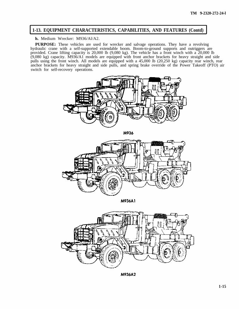
h. Medium Wrecker: M936/Al/A2.PURPOSE: These vehicles are used for wrecker and salvage operations. They have a revolving
hydraulic crane with a self-supported extendable boom. Boom-to-ground supports and outriggers areprovided. Crane lifting capacity is 20,000 lb (9,080 kg). The vehicle has a front winch with a 20,000 lb(9,080 kg) capacity. M936/A1 models are equipped with front anchor brackets for heavy straight and sidepulls using the front winch. All models are equipped with a 45,000 lb (20,250 kg) capacity rear winch, rearanchor brackets for heavy straight and side pulls, and spring brake override of the Power Takeoff (PTO) airswitch for self-recovery operations.
1-15
TM 9-2320-272-24-1
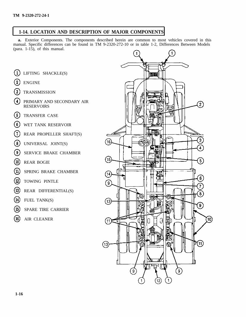
1-14. LOCATION AND DESCRIPTION OF MAJOR COMPONENTS
a. Exterior Components. The components described herein are common to most vehicles covered in thismanual. Specific differences can be found in TM 9-2320-272-10 or in table 1-2, Differences Between Models(para. 1-15), of this manual.
LIFTING SHACKLE(S)
ENGINE
TRANSMISSION
PRIMARY AND SECONDARY AIRRESERVOIRS
TRANSFER CASE
WET TANK RESERVOIR
REAR PROPELLER SHAFT(S)
UNIVERSAL JOINT(S)
SERVICE BRAKE CHAMBER
REAR BOGIE
SPRING BRAKE CHAMBER
TOWING PINTLE
REAR DIFFERENTIAL(S)
FUEL TANK(S)
SPARE TIRE CARRIER
AIR CLEANER
1-16
TM 9-2320-272-24-1
1-14. LOCATION AND DESCRIPTION OF MAJOR COMPONENTS (Contd)
Key1
2
3
4
5
6
7
8
9
10
11
12
13
14
15
16
Item and FunctionLIFTING SHACKLE(S) - Permit vehicle to be towed by another vehicle or used for tiedownattachment when transporting vehicle.ENGINE - There are two different Cummins model engines used, the NHC 250 (M939/A1 seriesvehicles) and 6CTA8.3 diesel (M939A2 series vehicles), which provide mechanical power to thevehicle and engine-driven subsystems.TRANSMISSION - The Allison MT546CR automatic, used on all M939/A1/A2 series vehicles,adapts the engine’s output for a varying range of operating speeds.PRIMARY AND SECONDARY AIR RESERVOIRS - Provides storage of compressed air andisolation between air subsystems.TRANSFER CASE - Directs the engine and transmission output to the specified axles and/orauxiliary equipment.WET TANK RESERVOIR - Provides reserve storage of compressed air created by the aircompressor or external source when demand is low and releases it when required. This lessens thecycling of the engine-driven air compressor.REAR PROPELLER SHAFT(S) - Transmits power between transfer case and forward-rear axleassemblies, and between forward-rear and rear-rear axles assemblies.UNIVERSAL JOINT(S) - Provides a flexible point between a component and the propeller shafts.This allows components that cannot maintain precision alignment to transfer power from one pointto another, without undue stress or breakage.
SERVICE BRAKE CHAMBER - Mechanical brake actuator that is activated by applying airpressure to an expandable cylinder, causing it to apply braking force to the brakedrum.
REAR BOGIE - The suspension system comprised of both rear axles, upper and lower torque rods,springs, and seats that support the rear vehicle weight.
SPRING BRAKE CHAMBER - Mechanical brake actuator that is spring-loaded to apply brakeswhen air is low or not present. During normal vehicle operation, air piston counteracts the springtension and allows the brakes to release. Spring brakes can be bypassed by pushing in the springbrake OVERRIDE switch on the instrument panel, or released using procedures found in TM 9-2320-272-10.
TOWING PINTLE - Provides a secure quick-connect/disconnect for towing vehicles or equipment.
REAR DIFFERENTIAL(S) - Bi-directionally transfer power from the propeller shaft to the axles,and provide a straight-through connection to power additional propeller shafts.FUEL TANK(S) - Provides storage of fuel.SPARE TIRE CARRIER - Stores spare tire. Davi t - Used to load and unload spare tire on M923/A1/A2, M925/A1/A2, M927/A1/A2,
M928/A1/A2, M931/A1/A2, and M9321/A1/A2 model vehicles.
Winch and Swinging Davit - Used to load and unload spare tire on M934A1/A2 model vehicles.Optional kit is available for M934 model vehicle.
Hoist and Lifting Eye - Used to load and unload spare tire on M929/A1/A2, M930/A1/A2, andM934 model vehicles. Optional kit is available to support dump bed in semi-raised position duringtire removal.
Vehicle Crane - Used to load and unload spare tire on M936/A1/A2 model vehicles. NOTE: OnM936/A1/A2 model vehicles, remove spare tire prior to changing tire, and install tire in spare tirecarrier after tire change is complete. Operation of crane and/or vehicle engine while vehicle is onjacks may cause the vehicle to slip off jack.
AIR CLEANER - Filters air before it enters the intake manifold or turbocharger and collects dust inremovable section of filter canister.
1-17
TM 9-2320-272-24-1
1-14. LOCATION AND DESCRIPTION OF MAJOR COMPONENTS (Contd)
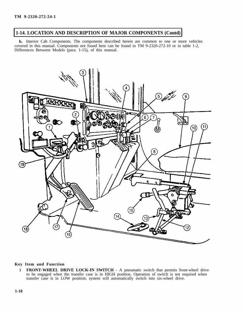
b. Interior Cab Components. The components described herein are common to one or more vehiclescovered in this manual. Components not found here can be found in TM 9-2320-272-10 or in table 1-2,Differences Between Models (para. 1-15), of this manual.
Key Item and Function
1 FRONT-WHEEL DRIVE LOCK-IN SWITCH - A pneumatic switch that permits front-wheel driveto be engaged when the transfer case is in HIGH position. Operation of switch is not required whentransfer case is in LOW position; system will automatically switch into six-wheel drive.
1-18
TM 9-2320-272-24-1
1-14 LOCATION AND DESCRIPTION OF MAJOR COMPONENTS (Contd)
Key2
34
5
6
7
8
9
10
11
12
13
14
15
16
17
18
19
Item and Function
POWER TAKEOFF (PTO) SPRING BRAKE OVERRIDE SWITCH - Used during rear winchself-recovery operations of M936/A1/A2 model vehicles only. This air control switch must be held in tooverride spring brake air dump switch on transfer case PTO lever.INSTRUMENT PANEL - Houses controls and indicators.
TRANSMISSION SELECTOR LEVER - Manual control to select driving gear.
SPRING BRAKE OVERRIDE SWITCH - Pressed in to release spring brakes independent of themechanical parking brake for tests and adjustments. Can be used to release spring brakes in theevent a leak or stoppage occurs in lines between primary and spring brake reservoirs, or primarysystem air shutoff valve is closed.TRANSMISSION POWER TAKEOFF (PTO) LEVER - Used on M925/A1/A2, M928/A1/A2,M929/A1/A2, M930/A1/A2, M932/A1/A2, and M936/A1/A2 model vehicles only. Provides hydraulicpower for front winch and/or dump body operation.
WINCH CONTROL LEVER - Provides control of winch unwinding and winding operations frominside the cab.TRANSFER CASE SHIFT LEVER SWITCH - Used in conjunction with transmission selectorlever in NEUTRAL position to allow transfer case to be shifted between HIGH and LOW gears.
PASSENGER SEAT - Combination two-person crew seat, battery box, and storage box. Seats areequipped with two sets of seatbelts, the battery box houses four batteries, and the storagecompartment stores technical manuals. NOTE: Ensure companion seatbelts are not caught insidebattery box.TRANSFER CASE SHIFT LEVER - Pushed down to shift transfer case into HIGH gear, centerposition for NEUTRAL, and up position for LOW gear. When transfer case is placed in LOW, it willautomatically engage six-wheel drive. In HIGH, the instrument panel-mounted front-wheel drivelock-in switch must be used to achieve six-wheel drive operation.
SPRING BRAKE CONTROL SWITCH - Senses the position of the parking brake control lever andsignals the spring brakes to engage when the lever is up and disengage when it is down. Springbrakes can be tested independently from parking brake by raising this switch without pulling up theparking brake control lever (TM 9-2320-272-10).
(a) DUMP BODY CONTROL LEVER - Used on M929/A1/A2 and M930/A1/A2 to control raising(pulled back) and lowering (pushed forward) of dump body.(b) TRANSFER CASE POWER TAKEOFF (PTO) - Used on M936/A1/A2 to control the hydraulicpump that delivers hydraulic pressure to the rear winch and crane. A spring brake air dump switchis installed on the lever when used on these vehicles, which engages the spring brakes. To overridethis feature during self-recovery operation with the rear winch, the driver must depress and hold thePTO spring brake override air switch on the instrument panel.DUMP BODY CONTROL LEVER SAFETY LATCH - Secures dump body control lever or transfercase PTO in NEUTRAL when not in use.FUEL TANK SELECTOR LEVER - Used on dual tank model vehicles only. NOTE: Tanks must beswitched periodically to lessen the buildup of contaminants and fungus.
PARKING BRAKE CONTROL LEVER - Pulled up to set mechanical brake on output of transfercase and to engage the spring brakes, and down to disengage brakes. Knob on top of handle is turnedclockwise to increase braking action on the output of transfer case, and counterclockwise to decreasebraking action. Spring brakes engagement is controlled by the spring brake control switch located onthe back of the lever.ACCELERATOR PEDAL - Foot control to vary the speed of the engine.
BRAKE PEDAL -Applies the service brakes.DIMMER SWITCH - Depressed to change between HIGH and LOW beam setting on headlights.
FUEL GAUGE TANK SELECTOR SWITCH - Used to switch fuel gauge to read either left or rightfuel tank. Installed only on dual tank model vehicles.