1 RDP Customer Document TECHNICAL MANUAL MODULAR 600 SYSTEM TYPE MODULAR 600 SYSTEM Doc. Ref CD2010AC This manual applies to units of mod status 6 ONWARDS BS EN ISO 9001 Certificate No. FM13141 Affirmed by Declaration of Conformity USA & Canada All other countries RDP Electrosense Inc. RDP Electronics Ltd 2216 Pottstown Pike Pottstown, PA 19465 U.S.A. Grove Street, Heath Town, Wolverhampton, WV10 0PY United Kingdom Tel (610) 469-0850 Fax (610) 469-0852 Tel: +44 (0) 1902 457512 Fax: +44 (0) 1902 452000 E-mail [email protected]www.rdpe.com E-mail: [email protected]www.rdpe.com
Transcript
1
RDP Customer Document
TECHNICAL MANUAL
MODULAR 600 SYSTEM
TYPE MODULAR 600 SYSTEM
Doc. Ref CD2010AC
This manual applies to units of mod status 6 ONWARDS
BS EN ISO 9001 Certificate No. FM13141
Affirmed by Declaration of Conformity
USA & Canada All other countries RDP Electrosense Inc. RDP Electronics Ltd
Fig. 9 Outline of Modular 600 Case Frames.................................................................. 22
3
1 Introduction This is a modular instrumentation system based on plug-in Eurocards (160 x 100mm). The signal amplifiers have 25mm wide (5HP) front panels and a standard full rack arrangement would comprise typically twelve dual channel amplifiers, a monitor/selector module and a power supply module. If a monitor is not required, then up to fifteen amplifiers may be fitted. All modules, apart from the power supply, plug into a back-plane interconnection panel. This back-plane also carries circular DIN connectors for external connection of transducer inputs and signal outputs. The signal amplifier modules also have the output signals available at front panel jack sockets. Generally amplifier modules supply excitation and signal conditioning for various ac and dc transducers (LVDTs, load cells, etc.) and amplifier outputs and excitation levels may be monitored via an 81mm (16HP) wide digital monitor providing ±10.000 display for ±10v signals and RS232 interface. Modules accommodated include:
650 Computer Interface As 635 plus RS232 interface 12 9A,B,EX)
651 Expansion Module Additional racks 26/164
660/1 Rack Selectors With 605 plus 635 or 636 N/A
600PCB Prototyping Circuit Board Various Any
The standard housing for these modules is a full width (84HP) case frame (MOD604). This housing is basically a case fitted with module guides - it does not require a separate card frame. Other size housings are available at "3/4" (60HP) and "1/2" (42HP). Larger 2- and 3-rack housings are also included. Each module type has a specific Technical Manual containing connection, setting-up and specification details, apart from the 631 & 632, details of which are contained in this document. Figure 2 shows various standard system configurations. However, special systems may be supplied; please refer to the Sales Department.
We declare that the product described in this technical manual is manufactured by
RDP Electronics Limited and performs in conformity to the following:
The Electromagnetic Compatibility Directive 2014/30/EU
The Low Voltage Safety Directive 2014/35/EU
RoHS2 Directive 2011/65/EU
R D Garbett
Director
RDP Electronics Limited
5
1.2 Electrical Safety Checks This instrument was checked for electrical safety using a portable appliance test instrument prior to despatch. If the user wishes to carry out his own tests, the following points must be followed: (a) This Safety Class 1 apparatus has a low (<3A) fuse rating and a low current rated
power connection cable. (b) It is recommended that when carrying out an earth bond test, a test current of 8A
should be applied for not more than six seconds. (c) In general it is not recommended that high voltage (e.g. 1.5kV) insulation tests are
carried out. This could cause damage to suppressor components.
1.3 Installation Before powering up, check:-
1 The supply voltage is correct to suit the 631/632 unit fitted and input range selected
2 The various plug-in modules are in the correct positions in the housing.
3 The input and output plugs are in the correct sockets. Note that on the housing back-plane all input sockets and all output sockets are of the same type.
4 Before connecting a transducer, ensure that the correct excitation voltage has been set. Too high a voltage can destroy a transducer
5 That each module has a unique address. (see section 9)
6 Where the system contains 615, 621 or 626 modules, one of them MUST be configured as a master and all others MUST be configured as slaves.
Note: Ensure system is switched OFF when removing or replacing modules and ensure
each module has a unique address. Failure to do so may cause damage to modules. For larger systems, or where the housings have restricted air flow around them, then fan cooling should be used. See Section 5.3.
1.4 ESD Precautions The user should take precautions against electrostatic discharge from himself to the equipment. The equipment is generally resistant to ESD but it is recommended that the user earth himself by means of an earthed wrist strap or at least touching earth before handling the plug-in modules.
1.5 EMC Conditions & Performance For full electromagnetic compatibility immunity, all signal input and output cables to the M600 backplane should be shielded with multi-core types. The shields should be terminated at the DIN connectors so that they bond correctly to the grounded shell of the connector. Also, all slots in the housing must be fitted with either a module or blank panel. Notes: (a) Cable shields to be grounded at only one end - the M600 end.
(b) When the M600 is a small part of a large electrical installation, ensure the cables to and
from the M600 are segregated from electrically noisy cables.
6
(c) Ensure cables to and from the M600 are routed away from any obviously powerful sources of electrical noise, e.g. electric motor, relays, solenoids.
(d) The transducer body should be grounded. Some transducers such as LVDTs, load cells, etc. without an internal body-to-shield connection, require a separate ground. This should preferably be connected to the instrument shield terminal or as near (electrically) as possible to this point.
See Section 11 for further application details. EMC Performance When subjected to radiated electromagnetic energy (as EN 61000-4-3) an additional measuring error can occur at certain frequencies:
Field Strength Typical Maximum Error
10V/m 2%
3V/m 0.2%
1.6 CE Marking
The 600 System is CE marked to denote compliance with both the EMC Directive and the Low Voltage Safety Directive. Note that it is the complete system that is marked; the individual modules are not marked. These are considered sub-assemblies and are only fully compliant with the Directives when correctly installed in one of the housings (e.g. 602, 603, 604 or 605, etc.). Fig. 1 A typical Mod.600 System
7
2. SYSTEM MODULES
611 Two separate channels of excitation, variable 1 – 10v with remote sense, or ±15v fixed. Two separate amplifiers giving ±10v or 4 -20mA output for signals in the range 5mV to 10v, ±100% suppression. Front panel controls for gain, zero, excitation and shunt calibration. Output jack for monitoring A and B signals. Gain range x1 to x2000.
615 Constant current excitation, various frequencies, synchronous demodulation for PY and LIN high temperature half-bridge transducers. Linearisation for PYs. Front panel controls for zero, span, balance, calibration, output suppression and gain. Master/slave system reduces excitation oscillator beating effects. Single channel, ±10v or 4-20mA output. Signal range 10mV to 10v.
621 Common excitation normally 5kHz, 1v, with separate signal amplifiers for two transducers. Synchronous demodulation for 30mV - 10V signals to provide ±10V dc or 4 - 20mA outputs, ±100% suppression. Front panel controls for gain, zero and zero-input selection. Output jack for monitoring A and B signals. Master/slave system reduces excitation oscillator beating effects. Gain range x1 to x330.
626 As for 621 but with the facility to calculate signals from the two channels giving switch selectable outputs of: A, B, average (A+B)/2, difference (A-B), sum A+B. Output ±10V.
628 Excitation 1 to 10V dc with remote sense and high stability amplification for quarter-, half- and full-bridge strain gauges. Output 10V and 4-20mA for 100, 1k, 10k and 100kμε signal ranges. Front panel controls for gauge factor, με range, shunt calibration, auto/manual balance, fine zero and gain. Internal controls include bandwidth, number of gauges, etc. This is a single channel unit.
631 A stabilised power supply converting ac supply to ±15V stabilised dc to power the signal conditioning modules. Input voltage selectable: 115/230V, +10% -15%. Later models have universal input range.
632 As for the 631 but with nominal dc inputs of 12V, 24V, -25% +50%.
635 Display ±10000, 10mm red LED, for ±10V signal, decimal point selectable. Channel selection via (a) 12-way rotary switch for channels 1 - 12, and (b) push-button switches for selection of channel A/B signals or excitation level.
8
636 As for 635 plus push-button selection of display of peak, trough or TIR values and reset of peak/trough values.
641 Provides an output signal which is the average or sum (641A) of the outputs of four transducer channels.
642 As 641 but for three channels only.
650/
651
The 650 is a computer interface and display (similar to 635/6). The 651 expansion modules allow up to 256 systems to be controlled/monitored.
681 Four separate limit-level detectors covering ±10V signal range. Each selectable as high or low limit. Logic or relay (normally open/closed, energised/de-energised) outputs. Selectable hysteresis (3 values), LED indication of limit status. Front panel controls for level setting, 4-way switch to select level output to 635 monitor or front panel jack.
3. SYSTEM HOUSINGS: The 602-605 housings are 3U or 6U high Eurocard enclosures which may be either free-standing, with adjustable tilt feet, or 19in rack-mounted via rack-mounting brackets.
602 42HP wide. Can be fitted with an eight-channel backplane, a six-channel if a 631 is to be fitted, or a three-channel if a 635 is to be fitted.
603 63HP wide. Can be fitted with a twelve-channel backplane, a ten-channel if a 631 is to be fitted, or a seven-channel if a 635 is to be fitted.
604 84HP wide. Fitted with a full size backplane for 12 or 15 channels.
605 A 2-rack high housing equivalent to 2 x 604 in one case.
600R A rack-only type housing: no case, no backplane.
600R-BP A rack-only type housing with backplane.
606 A 3-rack high case housing three 600R-BP racks.
607 A 4-rack high case housing four 600R-BP racks.
The 602, 603, 604 and 605 are all complete with front-mounted carrying handles. The 606 and 607 cases are based on a welded steel case tube to which the front frame and rear panel are attached via screws. A glass door is available. These both have integral cooling fans. Notes on widths: 1. 1 HP = 5.08mm = 0.2 inches
2. 611, 615, 621, 626, 628, 651, 660, 681 all 5 HPwide 3. 631 and 632 are 8 HP wide 4. 635, 636 and 650 are 16 HP wide.
9
1
2
3
4
5
6
7
635 MONITOR
OR 650 DATA
LOGGER
(8) (9) (10)
631 OR 632
P.S.U.
Fig. 2 System Configurations 604
603
602
Note 1. 635/650 can be mounted in any position 1-13. 2. User may affix number label in the space provided on each module handle.
1
2
3
4
5
6
7
8
9
10
11
12
635 MONITOR
OR 650 DATA
LOGGER
(13)(14)(15)
631 OR 632
P.S.U.
1
2
3
635 MONITOR
OR 650 DATA
LOGGER
(4) (5) (6)
631 OR 632
P.S.U.
10
Fig. 3 Schematic Diagram with 635/6 Monitors
10
.00
0
RE
SE
T
TIR
R
AC
K
CH
AN
NO
RM
INP
UT
12
A
B
EX
CH
AN
NE
L (6
36)
(650)
MO
NIT
OR
63
5/6
36
EX
C.
A
S/H
B
S/H
CH
AN
No. S
W
DIG
ITA
L
CO
MP
AR
AT
OR
L1
+
10V
LE
VE
L 1
-10V
RL
INP
UT
1
L2
+
10V
LE
VE
L 2
-10V
INP
UT
2
L3
+
10V
LE
VE
L 3
-10V
INP
UT
3
L4
+
10V
LE
VE
L 4
-10V
INP
UT
4
4
3
2 1
TR
AN
SD
UC
ER
AM
PL
IFIE
RS
61
1,6
21
AN
D 6
26
LIM
ITS
DE
TE
CT
OR
68
1
EX
C.
EX
CIT
O/P
A
O/P
B
RE
SE
T
INP
UT
A
EN
AB
LE
C
HA
N N
o. S
W
DIG
ITA
L
CO
MP
AR
AT
OR
EX
CIT
S
MU
X
B O
UT
PU
TS
MU
X
A O
UT
PU
TS
MU
X
16
CH
AN
NE
L
AD
DR
ES
S
EN
AB
LE
INP
UT
B
11
Fig. 4 Schematic Diagram with 650 Interface
C
OM
PU
TE
R IN
TE
RF
AC
E 6
50
EX
C.
A
S/H
B
S/H
CH
AN
No. S
W
DIG
ITA
L
CO
MP
AR
AT
OR
L1
+
10V
LE
VE
L 1
-10V
RL
INP
UT
1
L2
+
10V
LE
VE
L 2
-10V
INP
UT
2
L3
+
10V
LE
VE
L 3
-10V
INP
UT
3
L4
+
10V
LE
VE
L 4
-10V
INP
UT
4
4
3
2 1
TR
AN
SD
UC
ER
AM
PL
IFIE
RS
61
1,6
21
AN
D 6
26
LIM
ITS
DE
TE
CT
OR
68
1
EX
C.
EX
CIT
O/P
A
O/P
B
RE
SE
T
INP
UT
A
EN
AB
LE
C
HA
N N
o. S
W
DIG
ITA
L
CO
MP
AR
AT
OR
EX
CIT
S
MU
X
B O
UT
PU
TS
MU
X
A O
UT
PU
TS
MU
X
16
CH
AN
NE
L
AD
DR
ES
S
EN
AB
LE
INP
UT
B
MIC
RO
PR
OC
ES
SO
R
AN
ALO
G
SW
ITC
H
16-B
IT
A-D
ME
MO
RY
BU
FF
ER
INT
ER
FA
CE
RS
232 O
R
RS
485 O
R
RS
422
600 T
O
57k B
AU
D
10k
RE
AD
ING
S
(65k W
ITH
ME
1
OP
TIO
N)
CO
NT
RO
L
AD
DR
ES
S
TO
CO
NT
RO
L
FU
RT
HE
R
604S
(V
IA 6
51)
12
4. BASIC SYSTEM
4.1 Basic System Arrangement The system is based around the concept of a full 19" rack (604) containing 12 dual-channel amplifiers, a selector/monitor module (635) or interface (650) and a power supply (631). The 635 and 650 are designed to select and display the 12 or 24 outputs (depending on type) from the 12 amplifier modules, using a bus system, via the special analogue/digital backplane assembly. Larger systems can be configured with all the outputs displayed by the one 635 monitor via an additional rack selector switch module (660), or the 650 interface and 651 expansion modules. The limit module (681) set point voltages can be selected and displayed by the 635/650 to provide a uniform approach to signal presentation. For access to the backplane pcb, e.g. for addition of links to connect signals to 681 inputs, the rear panel can be removed by taking out the fixing screws. When re-installing, ensure the earthing wire tag is re-positioned correctly.
4.2 System Loading The maximum number of amplifiers which can be supported by the 631 or 632 power supply is dependent on (a) whether a system has a 635/636/650 monitor, (b) whether amplifier boards are configured for voltage or current (4-20mA) output, and (c) excitation loading. The tables below show typical examples, for use as a guide only:
Table 1 611 with 2 x 350Ω Bridges and 10V Excitation
Amplifier Output Maximum number of 611s per System
*1 : limited by space
Without 635/6/650 With 635/6/650 Voltage (V) 16 (15 per rack) *1 14 (12 per rack) *1
4-20mA (I) 12 11
Isolated V 12 11
Isolated I 9 8
Table 2 621 with 1V excitation and 2 x 100Ω LVDTs
Amplifier Output Maximum number of 621s per System
*1 : limited by space
Without 635/6/650 With 635/6/650 Voltage (V) 19 (15 per rack) *1 18 (12 per rack) *1
4-20mA (I) 14 13 (12 per rack)
Isolated V 14 13 (12 per rack)
Isolated I 11 10
13
Table 3 615 (10mA excitation)
Amplifier Output Maximum number of 615s per System
*1 : limited by space
Without 635/6/650 With 635/6/650 Voltage (V) 30 (15 per rack) *1 28 (12 per rack) *1
4-20mA (I) 23 (15 per rack) 21 (12 per rack)
Isolated V 23 (15 per rack) 21 (12 per rack)
Isolated I 16 (15 per rack) 14 (12 per rack)
Table 4 628 with 120Ω bridge, 5V excitation
Amplifier Output Maximum number of 628s per System
*1 : limited by space
Without 635/6/650 With 635/6/650 Voltage (V) 20 (15 per rack) *1 18 (12 per rack) *1
4-20mA (I) 17 (15 per rack) 16 (12 per rack)
Isolated V 15 14 (12 per rack)
Isolated I 15 13 (12 per rack)
4.3 Master/Slaving (for a.c. amplifiers only) To avoid beat-frequency effects, only one module per system controls the excitation frequency of all modules. This master module is usually fitted in channel one position (top rack of 605/6/7 systems), but can be fitted in any position. If a module is purchased on its own, it will be supplied as a master unless we are told otherwise. If it is then fitted into a system which already contains one or more 621, 626 or 615, it will need changing to a slave. Refer to technical manuals for 615, 621 or 626 for means of changing master to slave and vice versa.
5. MOUNTING/COOLING Mounting Details (Refer also to Section 3)
All modules, including the 635/636 monitors and 650/651 interfaces, may be mounted in any position in the racks except the 631 power supply which is normally factory-fitted in the extreme right-hand position, i.e. 611, 621, 681, etc. may be mixed in any configuration to suit the application. Note that as the 635/636/650 width is not a multiple of the normal module width, (i.e. 3.2 inches compared with 1 inch for 611, 621, etc.), repositioning this module may entail repositioning the pcb guides and backplane in the rack. Alternatively, blank panels can be supplied to fill any gaps introduced (check with Sales Department).
5.1 Rack mounting
All systems may be rack mounted. The feet may be removed after prising off the plastic covers. If the system is to be rack-mounted, ensure that the vents in the top and bottom covers are not obstructed.
14
5.2 Bench Mounting. 602/3/4 case frames are fitted with adjustable feet. A combination of positions allows the unit to be configured to be flat, or to tilt to suit your preference. To adjust the feet on some models, prise off the plastic covers for access to the fixing screws. Ensure that the ventilation holes are not obstructed.
5.3 Cooling
The engineering of large systems can involve extra cooling as the total power dissipated per rack can be up to 75 watts. In general we would recommend forced air cooling for systems with two or more 604 housings full of modules mounted in the customer's own rack. A suitable source of forced air is a 1U high, 19" wide, axial fan tray. For customers who are engineering their own system, i.e. fitting our racks of modules into their own cases or racks, maybe along with other instruments, we would recommend that they buy and fit such a unit or something similar. If required, we can supply such a unit, 19" wide, 1.72" high and 10" deep, fitted with three fans. Note that the 604 (19" wide) housing has only limited ventilation. For forced air cooling we would recommend using the open rack (600R) fitted with a backplane= 600R (BP). This is the same price as the 604. The total engineering would involve provision for air to enter the fan unit from below. The air would be forced upwards through the racks of modules by the fans and there must be provision to vent the air from the top of the outer housing. The larger 606 and 607 housings are supplied with such a fan system, factory fitted. (Refer to 5.4 below).
5.4 606/607 Installation/Cooling
This system uses forced-air cooling via fans mounted in the base of the cabinet, under the bottom instrument rack. Air is drawn in around the feet at the base through a renewable filter, up through the fans and modules, then vented through louvres at the sides and rear. It is vital that these airways are not obstructed as dangerous overheating could result. The filter is accessed by loosening two quarter-turn fasteners underneath the case. Packs of three Replacement Filters are obtainable from Electrospeed, part number 24-0020K, or Schroff UK, part number 60235-152. The rear panel may be discarded, without adversely affecting cooling, if maximum accessibility to transducer/output connections is required. Alternatively the panel insert may be removed and the transducer cables, etc. passed through the resultant hole prior to connection to the sub-racks.
15
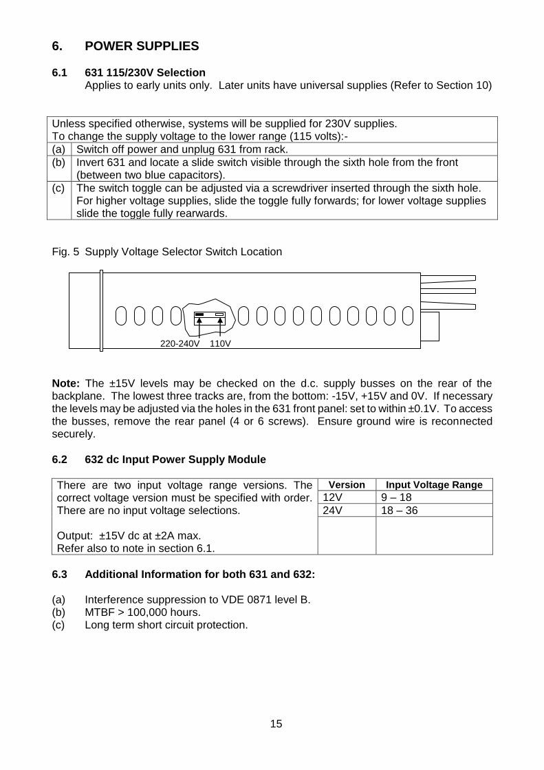
220-240V 110V
6. POWER SUPPLIES
6.1 631 115/230V Selection Applies to early units only. Later units have universal supplies (Refer to Section 10)
Unless specified otherwise, systems will be supplied for 230V supplies. To change the supply voltage to the lower range (115 volts):-
(a) Switch off power and unplug 631 from rack.
(b) Invert 631 and locate a slide switch visible through the sixth hole from the front (between two blue capacitors).
(c) The switch toggle can be adjusted via a screwdriver inserted through the sixth hole. For higher voltage supplies, slide the toggle fully forwards; for lower voltage supplies slide the toggle fully rearwards.
Fig. 5 Supply Voltage Selector Switch Location
Note: The ±15V levels may be checked on the d.c. supply busses on the rear of the backplane. The lowest three tracks are, from the bottom: -15V, +15V and 0V. If necessary the levels may be adjusted via the holes in the 631 front panel: set to within ±0.1V. To access the busses, remove the rear panel (4 or 6 screws). Ensure ground wire is reconnected securely.
6.2 632 dc Input Power Supply Module
There are two input voltage range versions. The correct voltage version must be specified with order. There are no input voltage selections. Output: ±15V dc at ±2A max. Refer also to note in section 6.1.
Version Input Voltage Range
12V 9 – 18
24V 18 – 36
6.3 Additional Information for both 631 and 632: (a) Interference suppression to VDE 0871 level B. (b) MTBF > 100,000 hours. (c) Long term short circuit protection.
16
7. CONNECTION DETAILS (Refer also to the Backplane description, Section 8)
7.1 A.C. Supply (with 631) Connection is made via the cable supplied which is fitted with an IEC standard type connector.
A line fuse is fitted in the slide-out carrier at the base of the power inlet.
Brown = ac live (115-230V)
Blue = neutral (0V)
Green/Yellow = ground
7.2 D.C. Supply (with 632)
Check rear panel to ensure correct supply Voltage is labelled, (12 or 24V). Connection is made via the 3-way rear panel connector as follows:
PIN 1 = dc positive Isolated
PIN 2 = dc negative (0V)
PIN 3 = ground
7.3 Transducers
These are connected via the backplane 7-pin plugs as detailed in the transducer amplifier type 611, 615, 621 and 626 Technical Manuals. The 628 strain gauge connection is via a special connector board which plugs into the two 7-pin connectors on the backplane. Refer also to section 8.
7.4 Analogue Outputs These are connected via the backplane 5-pin plugs as detailed in the transducer amplifier type Technical Manuals. Refer also to section 8.
7.5 Isolated Outputs (Option G) As section 7.4. Note that these outputs are isolated from the system ground and each other, except there is no isolation between channels on a dual channel amplifier.
7.6 Auxiliary Inputs/Outputs (Option 600IO) Multi-channel or system commands may be executed via the rear panel 8-pin connector when fitted. This is internally connected to the backplane busses to provide the function listed below. Refer also to Fig.7. The signals are opto-isolated (active high).
PIN FUNCTION 1 HOLD or 628 A-B 2 RESET 3 Common (0v) 4 628 S.Cal 5 Spare 6 +15v (not isolated)
7 +5v (not isolated) 8 0v (ground)
HOLD An external signal for use with 611, 615, 621, 626, 628 modules fitted with hold option. Cannot be used simultaneously with auto.Bal
628 A-B Remote auto Balance for 628 only - cannot be used simultaneously with HOLD.
RESET An external signal for resetting latched limits on the 681 module. (Duplicates function of front panel reset button.)
628 S.Cal Remote shunt calibration command signal for the 628 module. Cannot be used with M/S.
17
CHAN X
A
B
C
0A 0C
0B
A MS E
H
B
R
CHAN 1
A
B
C
0A 0C
0B
A MS E
H
B
R
CHAN 2
A
B
C
0A 0C
0B
A MS E
H
B
R
Auxiliary Input/ Output
Auxiliary Outputs Channels A & B
Chan B Trans-ducers
Optional HOLD & RESET Inputs
Channels A & B Outputs
Ac Supply
8. BACKPLANE (Refer also to Fig.6) The backplane provides an interface between the module 32-way connectors and the transducer and output signal connectors which are accessible from the rear of the case. Each module has two 7-pin transducer connectors for channels A and B, and one 5-pin output connector which provides both A and B output signals. Transducer connectors are labelled A and B and the output connectors C on the rear panel. To gain access to the backplane pcb surface, for example to link amplifier output signals to 681 inputs, the rear panel plate may be removed. This is done by taking out the fixing screws (6 on the 604) and lifting the panel out. At the top of the backplane four pcb tracks are provided to allow interconnection between modules via a set of four solder pads per channel. These are primarily intended for use with the limit module 681 and the facility is detailed in the Technical Manual for this module. The tracks may be used to interlink other modules. Refer to Fig.7. Fig. 6 Backplane Connections (rear view) with rear panel removed. ‘X’ depends on the size of the housing.
18
1
2 3 4 5 6 7 8 9
10 11 12 13 14 15 16 17
18 19 20 21 22 23 24 25
26 27 28 29 30 31 32
1 2 3 4 5 6 7 1
2 3 4 5
1 2 3 4 5 6 7 8
0A 0B 0C
1 2 3 4 5 6 7
CO
N 1
A
CO
N 1
B
CO
N 1
C
L1 L2 L3 L4
R
1
2 3 4 5 6 7 8 9
10 11 12 13 14 15 16 17
18 19 20 21 22 23 24 25
26 27 28 29 30 31 32
1 2 3 4 5 6 7 1
2 3 4 5
0A 0B 0C
1 2 3 4 5 6 7
CO
N 2
A
CO
N 2
B
CO
N 2
C
L1 L2 L3 L4
R
1
2 3 4 5 6 7 8 9
10 11 12 13 14 15 16 17
18 19 20 21 22 23 24 25
26 27 28 29 30 31 32
1 2 3 4 5 6 7 1
2 3 4 5
0A 0B 0C
1 2 3 4 5 6 7
CO
N X
A
CO
N X
B C
ON
XC
L1 L2 L3
A0 A1
A2 A3
+5V 0VD +15V -15V 0VA
CON 1 CON 2 ONWARD CON X (X DEPENDS ON CASE SIZE)
A B
E
MS H R
AUXILIARY INPUTS
OPTO-ISOL OPTION
Fig. 7 Backplane Circuit Diagram
9. ANALOGUE OUTPUT SIGNAL CONTENTION
9.1 When a system has no 635/636 monitor or 650/651 interface to address the amplifier/limit modules, the backplane address lines assume the state equivalent to a channel 0 address. To avoid the possibility of more than one output signal being connected simultaneously to the analogue output bus, ensure that all module pcb address switches are set to a different number (0 to 15) for each channel. Failure to do so may cause damage to modules.
9.2 For systems fitted with a 635/636 monitor or 650/651 interface, refer to the channel number switch description in the various module Technical Manuals. Note that in this case all the module switches must be set to a different address, i.e. to avoid output signal contention, no two modules can have the same address.
L4
19
10 SPECIFICATION 10.1 A.C. Supply Supply Voltage: Early 631 Modules 115 or 230V ac +10%; -22%; 47-63Hz (230V); 47-400Hz
(115V). Early 631 modules can be identified by noting two trimpot adjusters on the front panel. Later units have none.
Supply Voltage: Later 631 Modules 93 to 264V ac
Fuse: 2A anti-surge (T) 20 x 5mm (5A for 605/6)
631 Output: ±15V at 2A limited to 2.2A
Load Regulation: 0.5% (10-90% I out)
Supply Regulation: 0.2% (+10/-15% V in)
Ripple: 150mV peak to peak (Less when fitted into a 600 system)
Input Power: 80W at full load
Operating Temperature Range: 0°C to 55°C (Refer also to Section 1.3) -10°C to 40°C (606/7 – refer to Sections 5.2 & 5.3)
With Opto Isolated Input Option: Input voltage : 5-24v dc into 2kΩ Isolation : 2kv peak.
20
11. APPLICATION NOTE 11.1 Electrical Interference Problems When a system is used in an industrial application, some of the following points may be helpful to System Engineers to design a trouble-free installation. 1. In general the operation of electronic instruments and transducers can be affected by
electrical interference.
2. The switching of large or reactive loads on the supply, causing the production of large voltage spikes and/or variation in the ac mains supply can generate this interference. Higher frequency interference (radio frequency) is often generated by a large voltage (e.g. back emf from a coil) being switched by a contact. Generally a contact seen to arc whilst switching is producing RF interference.
3. The interference "signals" can enter a measuring system in the following ways: a) Direct pick-up by wiring to the instrument. The wiring can be a connection to the
transducer supply input or control (e.g. trip relay). b) Direct pick-up into the instrument. c) Along the mains supply lines.
4. There are two methods of countering these problems: a) Suppress the interference generation at source. b) Prevent the interference gaining access to the instrumentation circuitry.
5. Suppression at source is often the best approach. AC coils can often effectively be
suppressed by means of connecting, as close to the coil terminals as possible, a 100 ohm resistor in series with 0.1μF across the coil. Proprietary transient voltage clippers - either non-linear resistor or better semiconductor types - are very useful for suppression, mounted across coils and contacts.
6. An electrically noisy mains supply can be suppressed by means of a mains filter unit. These units in their simplest form consist of capacitors and inductors. Mounted at the point where the mains enters the instrument, they can be most effective. A constant voltage transformer is another effective way of cleaning up the mains.
7. Extra shielding of the transducer, cabling and instrument is a simple, low cost method of preventing particularly directed radiated RF type of interference. Screened cable should always be used to connect the transducer to the instrument. Screened cable is often beneficial for other connections as well. The screen should only be earthed at the instrument end. It is not good practice to mount the instrument near to contactors, motors, switch transformers, solenoids, etc. Where this is unavoidable, an extra steel enclosure around the instrument would be essential. In extreme cases, the transducer cable should be run in a steel conduit.
8. Trip relays in the 681 should never be used to switch ac coils. The recommended arrangement is to use a dc slave relay as shown in the following diagram.
21
Suppression Diode
Transient Clipper
RLS Slave Relay
Solenoid
RLS/1
d.c. Supply + -
a.c. Input
2k INPUT
COMMON
OPTO-COUPLER
2k
OPTO-COUPLER
5V SUPPLY
CLOSE TO OPERATE
2k
OPTO-COUPLER
12V SUPPLY
OPEN TO OPERATE
2k2
Wherever possible, TTL limit outputs should be used in order to: a) reduce noise problems, b) increase response speed, c) increase life especially in repetitive applications where relay contact life may be significant.
11.2 Opto Isolated Input Option For optimum EMC compliance or reduction of electrical noise effects on control signals, opto isolation is used for the optional external control for hold, reset, remote shunt calibration, etc. functions. The input circuit schematic, with application examples, is shown in Fig. 8. Fig. 8 Opto-isolated Input Applications (a) Input Circuit Schematic
(b) Typical External System Configuration
22
Fig. 9 Outline of Modular 600 Case Frames
Module A B C D E F G J
602
270 (10.63”)
252 (9.92”)
236 (9.29”)
282 (11.1”)
250 (9.8”)
133 (5.22”)
57 (2.25”)
279 (11.0”)
603
376 (14.8”)
358 (14.1”)
342 (13.5”)
“ “
“ “
“ “
“ “
385 (15.2”)
604
483 (19.00”
465 (18.30”)
449 (17.67”)
“ “
“ “
“ “
“ “
492 (19.4”)
605
“ “
324
(12.8”) 279
(11.0”) 266
(10.47”) “ “
606
“ “
345
(13.6”) 295
(11.6”) 400
(15.75”) “ “
607
“ “
“ “
“ “
533 (21.00”)
“ “
600R
“ “
“ “
“ “
“ “
“ “
133 (5.22”)
“ “
Refer to section 10.3 for overall dimensions of 605, 606 and 607
Feet H protrude 17mm from the bottom of the case – this adds 17mm to dimension F. The feet can be removed. Refer to section 5.1.
7 (0.275”) Holes
Feet H
D
E
C
A
B
F G
J
23
12. TROUBLESHOOTING 1. Dead system - no output/no display on 635. If LEDs out on 631 power supply, check
fuse in rear panel, check power wiring/fuses, etc. Check supply voltage correct for system - refer to Section 6.
2. If only one LED on 631, suspect amplifier module or signal/output wiring fault. Unplug outputs/transducer connections one at a time till LED lights. Check system not overloaded by excessive excitation current (affects +15v especially). Refer to Section 4. If faulty with no transducers/outputs connected, unplug modules one at a time. Check address switch settings. Refer to Section 9. If one channel clears the fault, try temporarily plugging another module into that channel. If fault recurs, then suspect a backplane connector fault. If O.K., check switch settings, etc. on "faulty" module (excitation, channel number, etc.) Check for solder shorts on the 32-way connector, especially on the lower 5 pins (supplies).
3. Output signals low/grossly non-linear - check channel address switches set correctly. Refer to Section 9. Check transducer wiring. Try substituting a "good" channel. Check correct gain range is set on amplifier board. Try next lowest gain range if in doubt. If using floating transducers with 611, 628, check one side of signal input is grounded (to 0v pin). If using LVDT or half-bridge transducers with 621, 615, etc., check setting up procedure particularly re setting initial zero output with armature at centre of working stroke.
4. Excessive output signal noise. Check transducer cable screen is connected either to connector 0v pin or via transducer mounting (if both are connected, an earth loop may cause the problem). If the transducer body is not grounded via the cable screen, ground it via a separate lead. If the outputs are monitored via equipment having an earth/ground connection, this again may cause earth loop problems. Try temporarily disconnecting either the M600 or monitor earth/ground wires or ground the two systems via one wire only. (Note: the output commons and signal 0v's of the M600 are internally connected to the M600 supply ground wire.)
5. Non-working trimmers. If a trimmer (fine zero, fine gain control, etc.) is at the end of its travel it can take up to three turns before it is back into its working range and any change in output is noticed.
24
13. WARRANTY AND SERVICE WARRANTY. R.D.P. Electronics products are warranted against defects in materials or workmanship. This warranty applies for one year from the date of delivery. We will repair or replace products that prove to be defective during the warranty period provided they are returned to R.D.P. Electronics. This warranty is in lieu of all other warranties, expressed or implied, including the implied warranty of fitness for a particular purpose to the original purchaser or to any other person. R.D.P. Electronics shall not be liable for consequential damages of any kind. If the instrument is to be returned to R.D.P. Electronics for repair under warranty, it is essential that the type and serial number be quoted, together with full details of any fault. SERVICE. We maintain comprehensive after-sales facilities and the instrument can, if necessary be returned to our factory for servicing. Equipment returned to us for servicing, other than under warranty, must be accompanied by an official order as all repairs and investigations are subject to at least the minimum charge prevailing at the date of return. The type and serial number of the instrument should always be quoted, together with full details of any fault and services required. IMPORTANT NOTES. 1. No service work should be undertaken by the customer while the unit is under
warranty except with the authorisation of RDP Electronics. 2. If the instrument is to be returned to R.D.P. Electronics for repair, (including repair
under warranty) it is essential that it is suitably packed and that carriage is insured and prepaid. R.D.P. Electronics can accept no liability whatsoever for damage sustained during transit.
3. It is regretted that the above warranty only covers repairs carried out at our factory.
Should the instrument have been incorporated into other equipment that requires our engineers to perform the repair on site, a charge will be made for the engineer's time to and from the site, plus any expenses incurred.
The aforementioned provisions do not extend the original warranty period of any product that has been either repaired or replaced by R.D.P. Electronics.