Description ..................................................................................................... 3 Typical performance data ANSI/IEC 118-7 .................................................. 4-6 Part No. lists ................................................................................................ 7-8 Programming cable ........................................................................................ 9 Microphone complete ................................................................................... 10 Receiver complete ........................................................................................11 Prepare the faceplate .............................................................................. 12-14 Hybrid connections.................................................................................. 15-17 FP fi nal assembly ......................................................................................... 18 Service Tool .................................................................................................. 19 Diagram........................................................................................................ 20 Document revision history ............................................................................ 21
Table of contents
Doc. No. 0012710 rev. D
Page 3 of 20
Technical Manual for Newtone Plus ITE-TDescription
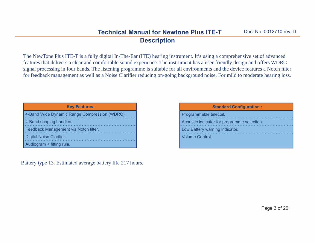
The NewTone Plus ITE-T is a fully digital In-The-Ear (ITE) hearing instrument. It’s using a comprehensive set of advanced features that delivers a clear and comfortable sound experience. The instrument has a user-friendly design and offers WDRC signal processing in four bands. The listening programme is suitable for all environments and the device features a Notch fi lter for feedback management as well as a Noise Clarifi er reducing on-going background noise. For mild to moderate hearing loss.
Battery type 13. Estimated average battery life 217 hours.
Key Features :
4-Band Wide Dynamic Range Compression (WDRC).
4-Band shaping handles.
Feedback Management via Notch fi lter.
Digital Noise Clarifi er.
Audiogram + fi tting rule.
Standard Confi guration :
Programmable telecoil.
Acoustic indicator for programme selection.
Low Battery warning indicator.
Volume Control.
Doc. No. 0012710 rev. D
Page 4 of 20
Technical Manual for Newtone Plus ITE-TTypical performance data - IEC 118-7
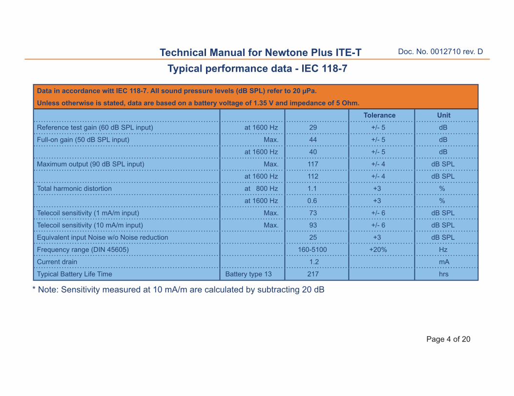
* Note: Sensitivity measured at 10 mA/m are calculated by subtracting 20 dB
Data in accordance witt IEC 118-7. All sound pressure levels (dB SPL) refer to 20 μPa.
Unless otherwise is stated, data are based on a battery voltage of 1.35 V and impedance of 5 Ohm.
Tolerance Unit
Reference test gain (60 dB SPL input) at 1600 Hz 29 +/- 5 dB
Full-on gain (50 dB SPL input) Max. 44 +/- 5 dB
at 1600 Hz 40 +/- 5 dB
Maximum output (90 dB SPL input) Max. 117 +/- 4 dB SPL
Equivalent input Noise w/o Noise reduction 24 +3 dB SPL
Frequency range 140-6300 +20% Hz
Current drain 1.2 mA
Typical Battery Life Time Battery type 13 217 hrs
Reference test gain settingsG (80) 23 23 23 23
G (50) 34 34 34 34
Full-on gain parameter settingsG (80) 30 30 30 30
G (50) 41 41 41 41
Doc. No. 0012710 rev. D
Page 6 of 20
Technical Manual for Newtone Plus ITE-TTypical performance data- IEC 118-7
2cc Coupler
Full-on and Reference Test Gain
Frequency: (Hz)
Full on Gain 50 dB SPL input
Reference Test Gain 60 dB SPL
100 1000 10000
60
50
40
30
20
10
0
130
120
110
100
90
80
70100 1000 10000
2cc Coupler
Maximum Output (OSPL 90)
Frequency: (Hz)
Doc. No. 0012710 rev. D
Page 7 of 20
Technical Manual for Newtone Plus ITE-TPart list
*Supplied by GNO.
Item Part No.
Microphone complete (R) 15239900
Microphone complete (L) 15239700
Mic. EM 9267/6392 15303400
Wire ESW 7x50μ, red 26 mm 15130026
Wire ESW 7x50μ, red 28 mm 15130028
Wire ESW 7x50μ, amber 26 mm 15130126
Wire ESW 7x50μ, green 26 mm 15130226
Coating, EGC-1700, 100 ml 15290401
Receiver complete 15239800
Receiver ED7926 15250900
Tubing, Q-fl ex, uncut 10038801
Tubing silicone, uncut 10929-000
Wire ESW 7x50μ, red 20 mm 15130020
Wire ESW 7x50μ, green 10 mm 15130210
Wire ESW 7x50μ, amber 24 mm 15130124
Flex hybrid C2.0, DENMARK 15120100
Wire ESW 7x50μ, green 30 mm 15130230
Wire ESW 7x50μ, amber 30 mm 15130130
Wire ESW 7x50μ, blue 25 mm 15130325
Resistor MCR01 MZS J 2K7 Rx2 70927753
Capacitor C-C-K0402 100 nF Cx2 70930579
Resistor MCR01 MZS J 1M Ohm Rx1 70922526
Item Part No.
Tube SKO. 5x0.3 / TRANSP. 5mm 75927517
Capacitor 0402 1μF Cx1 3122 150 73461
Wrap, 1.3mm x 7mm 14027-002
Windscreen / 10A-109540300 70931652
Windscreen / 10A-1095403007 70931664
Windscreen / 10A-1095403008 70931666
Switch SW96 / pink 70931603
Switch SW96 / tan 70931601
Switch SW96 / brown 70931602
Programming cable 50931702
Flex-strip (10 pcs) 50931703
Battery pill size 13 * 80B4813403
RS 10314-000 70923847
Tape, 3M double face 10038901
Telecoil 2238-429
Tubing silicone, uncut 11509-000
Resistor 510K 0402 Rx3 + Rx4 H685-514
Service tool 10158701
Wrap (6.8mm x 1.6mm) 14027-003
CEMENT CLEAR RTV#734 0139007
Double face tape 1.3mm x 3mm 10038902
Doc. No. 0012710 rev. D
Page 8 of 20
Technical Manual for Newtone Plus ITE-T Part list
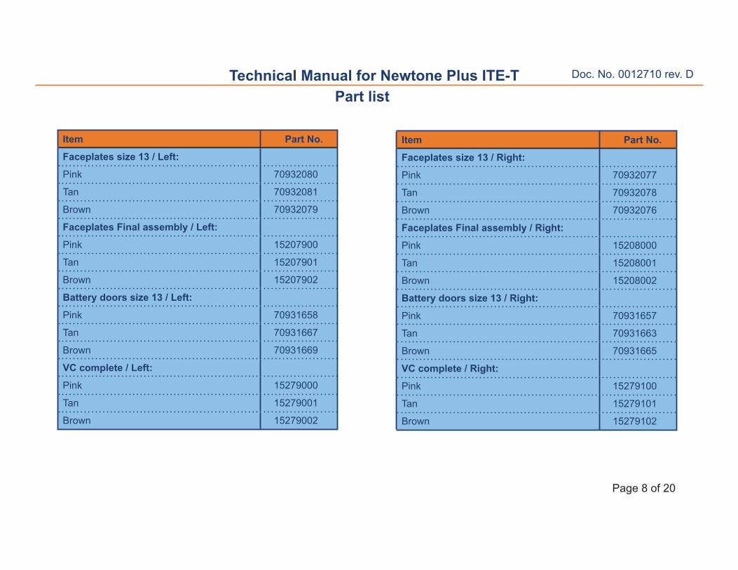
Item Part No.
Faceplates size 13 / Right:
Pink 70932077
Tan 70932078
Brown 70932076
Faceplates Final assembly / Right:
Pink 15208000
Tan 15208001
Brown 15208002
Battery doors size 13 / Right:
Pink 70931657
Tan 70931663
Brown 70931665
VC complete / Right:
Pink 15279100
Tan 15279101
Brown 15279102
Item Part No.
Faceplates size 13 / Left:
Pink 70932080
Tan 70932081
Brown 70932079
Faceplates Final assembly / Left:
Pink 15207900
Tan 15207901
Brown 15207902
Battery doors size 13 / Left:
Pink 70931658
Tan 70931667
Brown 70931669
VC complete / Left:
Pink 15279000
Tan 15279001
Brown 15279002
Doc. No. 0012710 rev. D
Page 9 of 20
Technical Manual for Newtone Plus ITE-TProgramming cable
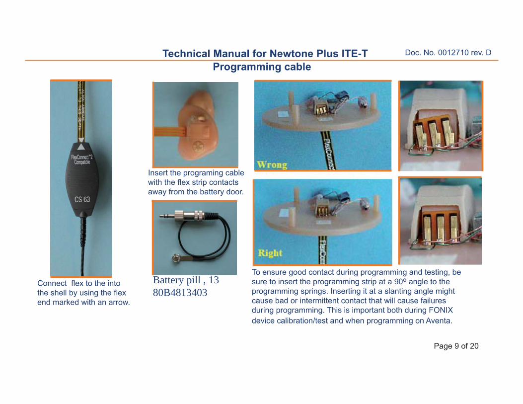
Insert the programing cable with the fl ex strip contacts away from the battery door.
Connect fl ex to the into the shell by using the fl ex end marked with an arrow.
To ensure good contact during programming and testing, be sure to insert the programming strip at a 90o angle to the programming springs. Inserting it at a slanting angle might cause bad or intermittent contact that will cause failures during programming. This is important both during FONIX device calibration/test and when programming on Aventa.
Battery pill , 1380B4813403
Doc. No. 0012710 rev. D
Page 10 of 20
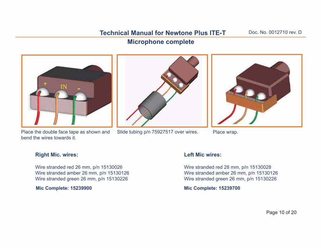
Technical Manual for Newtone Plus ITE-TMicrophone complete
Right Mic. wires:
Wire stranded red 26 mm, p/n 15130026Wire stranded amber 26 mm, p/n 15130126Wire stranded green 26 mm, p/n 15130226
Place the double face tape as shown and bend the wires towards it.
Place wrap.Slide tubing p/n 75927517 over wires.
Left Mic wires:
Wire stranded red 28 mm, p/n 15130028Wire stranded amber 26 mm, p/n 15130126Wire stranded green 26 mm, p/n 15130226
+ IN -
Mic Complete: 15239900 Mic Complete: 15239700
Doc. No. 0012710 rev. D
Page 11 of 20
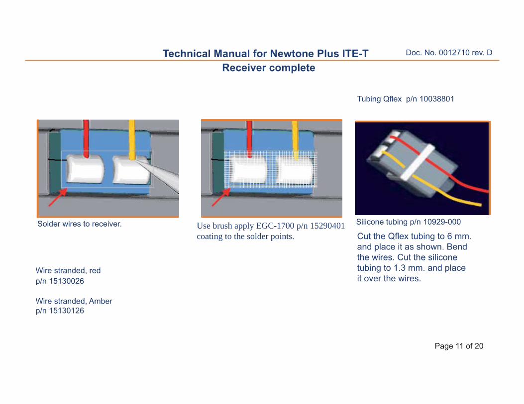
Technical Manual for Newtone Plus ITE-TReceiver complete
Wire stranded, red p/n 15130026
Wire stranded, Amber p/n 15130126
Solder wires to receiver. Silicone tubing p/n 10929-000
Tubing Qfl ex p/n 10038801
Cut the Qfl ex tubing to 6 mm. and place it as shown. Bend the wires. Cut the silicone tubing to 1.3 mm. and place it over the wires.
Use brush apply EGC-1700 p/n 15290401 coating to the solder points.
Doc. No. 0012710 rev. D
Page 12 of 20
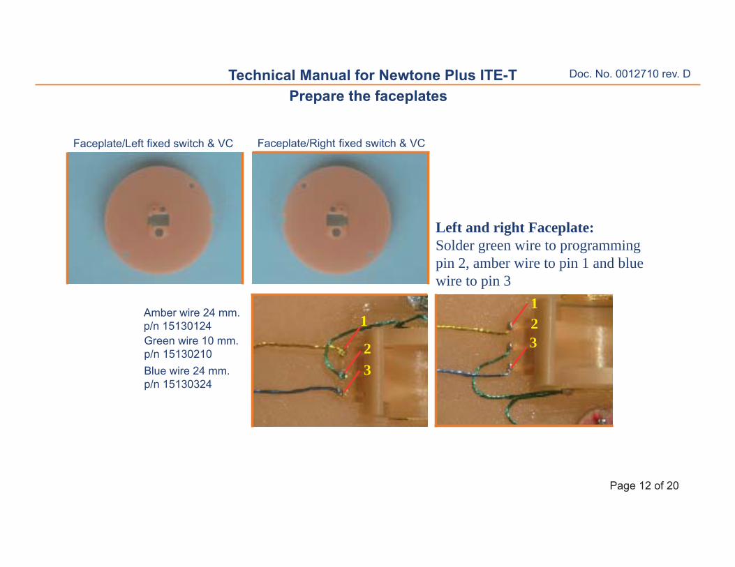
Technical Manual for Newtone Plus ITE-TPrepare the faceplates
Amber wire 24 mm.p/n 15130124
Blue wire 24 mm.p/n 15130324
Green wire 10 mm.p/n 15130210
Left and right Faceplate:Solder green wire to programming pin 2, amber wire to pin 1 and blue wire to pin 3
123
1
23
Faceplate/Right fi xed switch & VCFaceplate/Left fi xed switch & VC
Doc. No. 0012710 rev. D
Page 13 of 20
Technical Manual for Newtone Plus ITE-T
Glue round the switch using Loctite 406 p/n 1901-339.Make sure the black dot on the switch is placed as shown on the pictures.
Prepare the faceplate
Cut the three terminals of SW to 0.5 mm. with scissors.Verify the three terminals of SW have same length.
Pre-tin the two terminals .
0,5 mmFaceplate left Faceplate right
Solder the green wire 26 mm to B terminal of SW and the green wire 30 mm to A terminal.Bend the third terminal.
Apply Loctite 406 around edge of the microphone slot.Immediately place PF WSK/10A-109540300x in the slot.
AA
BB
Doc. No. 0012710 rev. D
Page 14 of 20
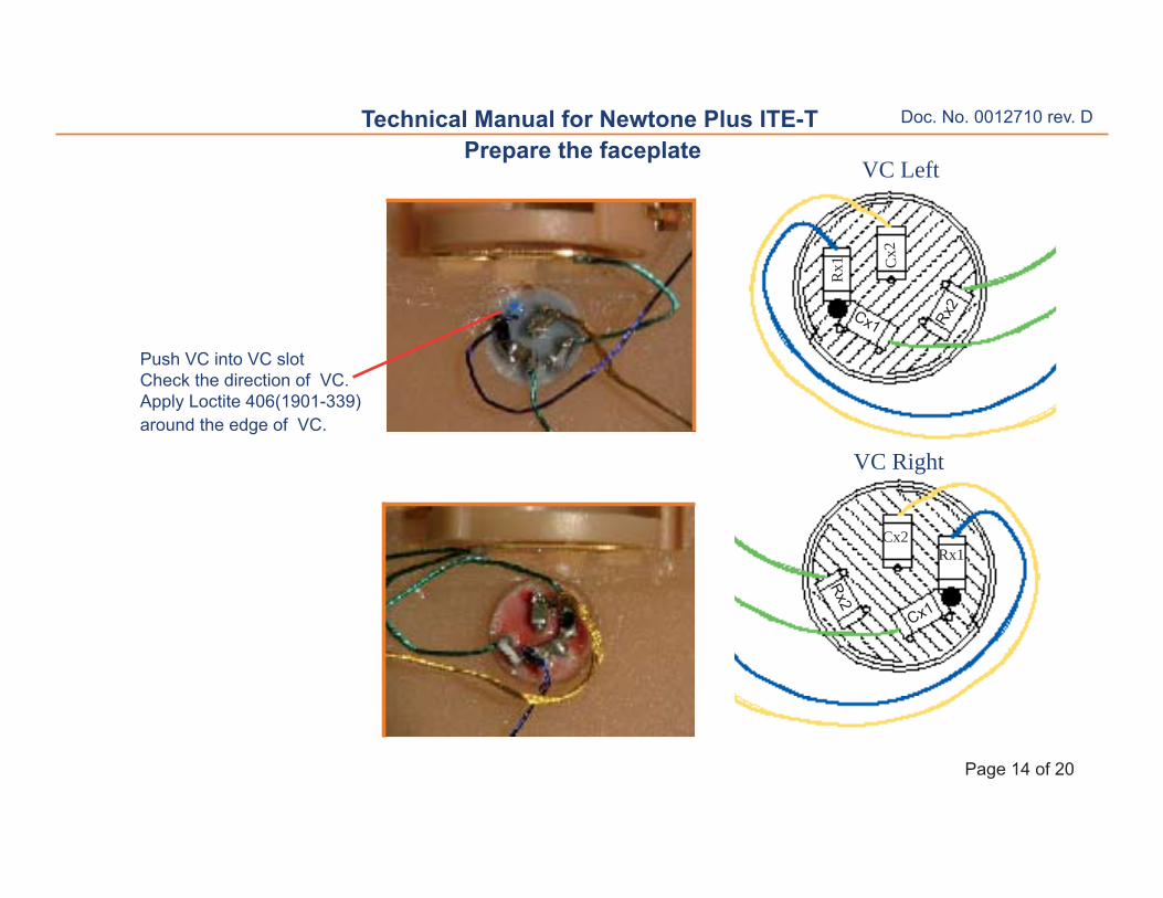
Technical Manual for Newtone Plus ITE-TPrepare the faceplate
Push VC into VC slotCheck the direction of VC.Apply Loctite 406(1901-339) around the edge of VC.
VC Left
VC Right
Cx2
Rx1
Cx2Rx1
Cx1Rx2
Rx2
Cx1
Doc. No. 0012710 rev. D
Page 15 of 20
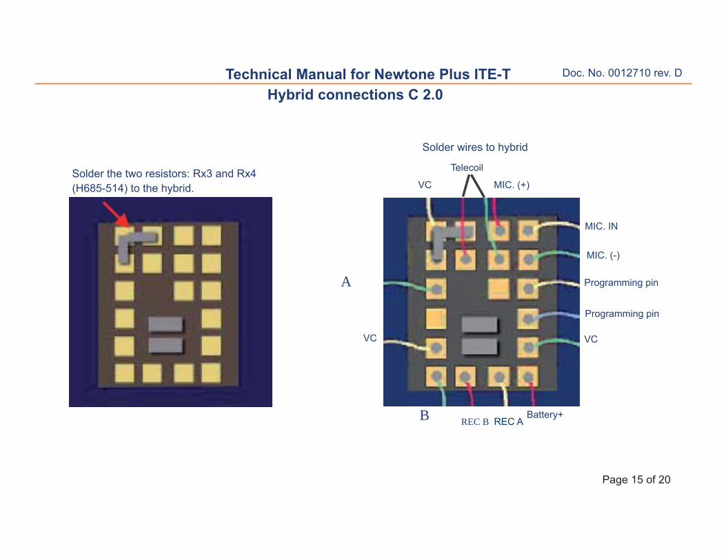
Technical Manual for Newtone Plus ITE-T
Solder the two resistors: Rx3 and Rx4(H685-514) to the hybrid.
REC AREC B
VC
Programming pin
Programming pin
VC
Battery+
VC
Solder wires to hybrid
MIC. (+)
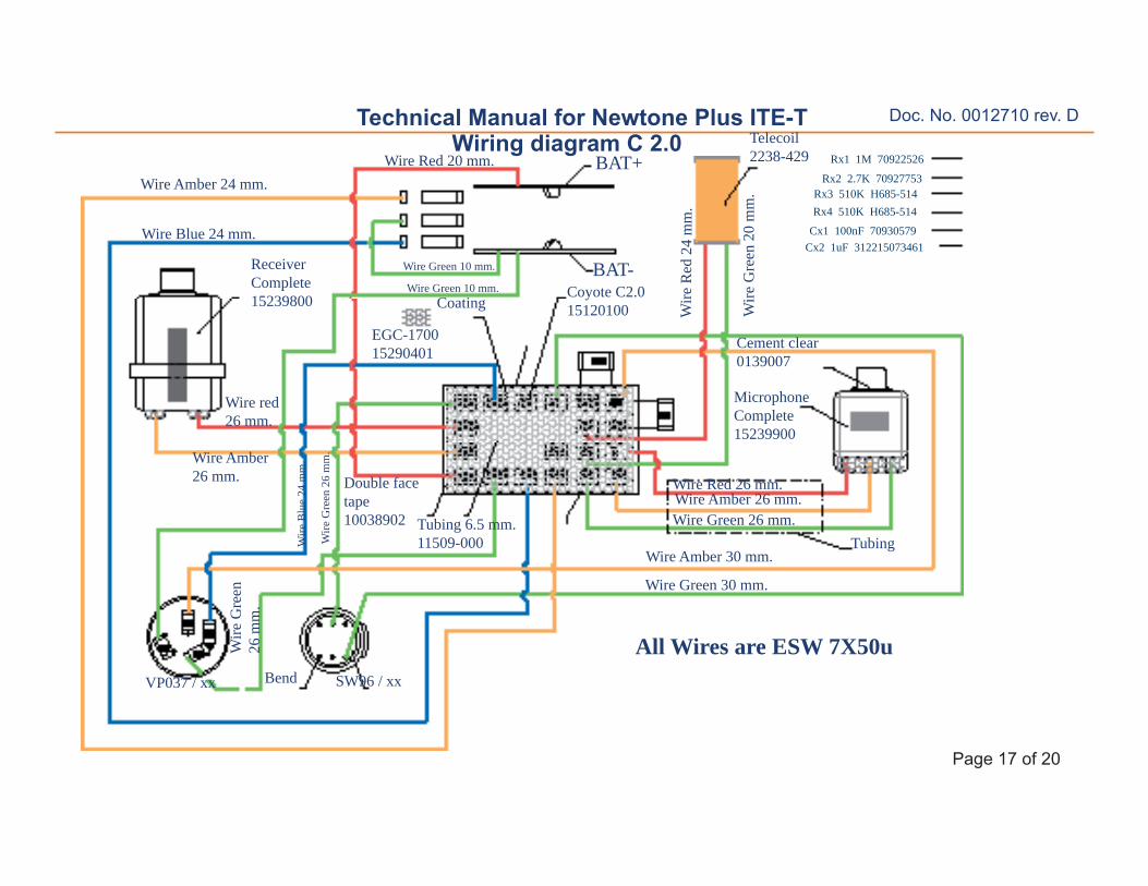
Hybrid connections C 2.0
MIC. (-)
MIC. IN
Telecoil
B
A
Doc. No. 0012710 rev. D
Page 16 of 20
Technical Manual for Newtone Plus ITE-T
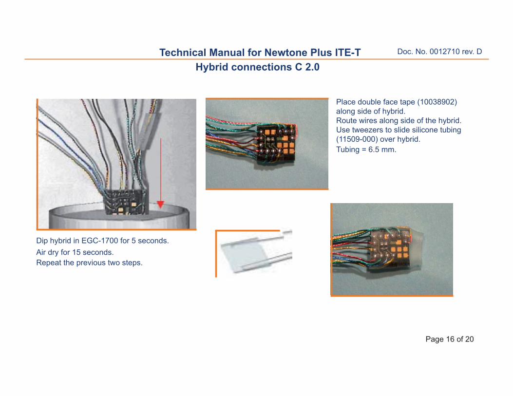
Place double face tape (10038902) along side of hybrid.Route wires along side of the hybrid.Use tweezers to slide silicone tubing (11509-000) over hybrid.Tubing = 6.5 mm.
Dip hybrid in EGC-1700 for 5 seconds.Air dry for 15 seconds.Repeat the previous two steps.
Technical Manual for Newtone Plus ITE-TFaceplate Size 13 Final assembly
Place the Batt.Contact Cover RS 10314-000 (70923847) tothe faceplate.Apply Loctite 406 (1901-339)around the edge of theBatt.Contact Cover RS 10314-000.Allow adhesive to cure for 1 minute.
Doc. No. 0012710 rev. D
Page 19 of 20
Technical Manual for Newtone Plus ITE-TService tool
The Tool can be used on both sides. One side for size 13 and the other side for size 10 and size 312.
When working on the assembled faceplate a heat sink (p/n 10158701) must always be used in order to prevent damages to the components.