Write the serial numbers from your Marsh equipment in the appropriate spaces on this page. If you need to call Technical Support, they will ask for this information.
Technical Support:
— Telephone – U.S. and Canada: 800-851-3441— Telephone – International: 618-234-9093— All FAX: 618-234-1265
Note: If you have more than one production line, you may want to copy this sheet and use one sheet per production line.
Controller
Printheads
Ink Systems
Power Supplies
Shaft Encoders
Task 2 Key
29669/02080 Rev AG
i
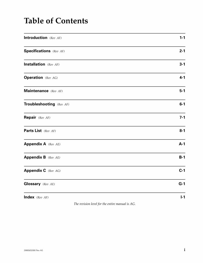
Table of Contents
Introduction
(Rev AF)
1-1
Specifications
(Rev AF)
2-1
Installation
(Rev AF)
3-1
Operation
(Rev AG)
4-1
Maintenance
(Rev AF)
5-1
Troubleshooting
(Rev AF)
6-1
Repair
(Rev AF)
7-1
Parts List
(Rev AF)
8-1
Appendix A
(Rev AE)
A-1
Appendix B
(Rev AE)
B-1
Appendix C
(Rev AG)
C-1
Glossary
(Rev AE)
G-1
Index
(Rev AF)
I-1
The revision level for the entire manual is AG.
29669/02080 Rev AF
1-1
1-Introduction
The Marsh PatrionPlus is a light weight controller with a tactile keypad and built-in LCD. It is capable of driving up to eight printheads on one production line. Using the dual tasking feature, the PatrionPlus can drive an additional eight printheads on a second production line.
The Marsh PatrionPlus VJ7 Series and theMarsh PatrionPlus VJ16 Series each consist of three printheads able to print on porous or non-porous surfaces. VJ7 printheads prints one line of 7x5 dot matrix print with heights ranging from 3/8" (10 mm) to 1" (26 mm). V16 printheads print one line of 14x10 dot matrix print or two lines of 7x5 dot matrix print with print heights ranging from 3/8" (10 mm) to 2" (50 mm).
All VJ printheads use the ADS Ink system with various sizes of ink containers.
The Marsh HR Series printheads consist of the HR/120 with 120 orifices, and the HR/300 with 300 orifices. Both yield 150 dpi vertical resolution. Print heights range from 0.25" (6 mm) to 0.8" (20 mm) for HR/120 printheads, and 0.38" (0.96 cm) to 2" (5.08 cm) for HR/300 printheads. HR Series printheads are designed to print on porous surfaces only using a Series 2000 ink system.
Technical Support
Videojet Technologies Inc. provides phone service and support 24 hours a day, seven days a week. For more information about the Marsh PatrionPlus system or other Marsh products, please contact your local distributor or Videojet Technologies Inc.
Videojet Technologies Inc.
Address: PO Box 388Belleville, IL 62222-0388USA
Telephone: USA and Canada (800) 527-6275 International (618) 234-1122FAX: (618) 234-1529Web Site: www.videojet.com
Technical Support
Telephone: USA and Canada (800) 851-3441 International (618) 234-9093FAX: (618) 234-1265E-mail: [email protected]
When calling Technical Support for help with a product please have the serial number for that product ready.
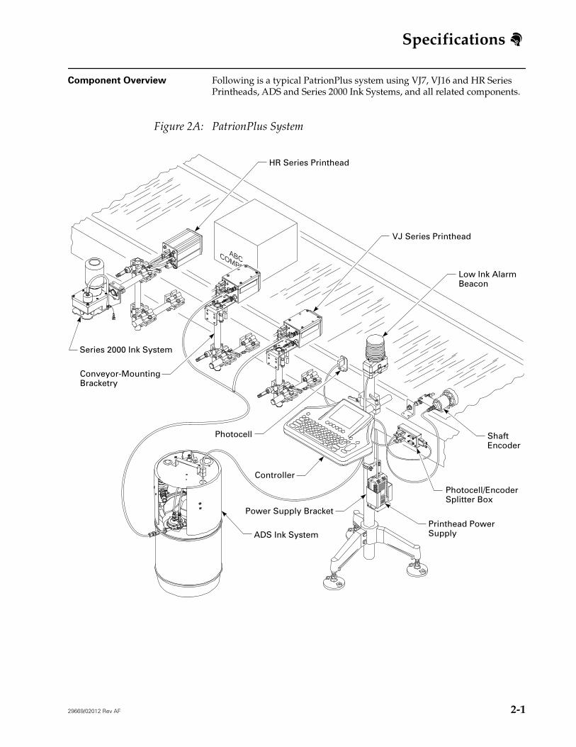
Following is a typical PatrionPlus system using VJ7, VJ16 and HR Series Printheads, ADS and Series 2000 Ink Systems, and all related components.
Figure 2A: PatrionPlus System
COMPANY
ABC
Low Ink AlarmBeacon
VJ Series Printhead
HR Series Printhead
ADS Ink System
Controller
Photocell
Conveyor-MountingBracketry
Printhead PowerSupply
Power Supply Bracket
Photocell/EncoderSplitter Box
ShaftEncoder
Series 2000 Ink System
2-
Specifications
2-2
29669/02012 Rev AF
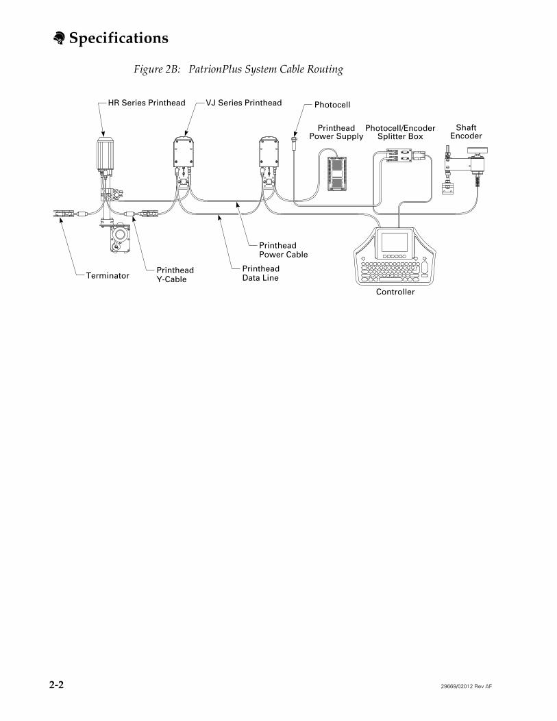
Figure 2B: PatrionPlus System Cable Routing
Controller
VJ Series PrintheadHR Series Printhead
PrintheadPower Cable
PrintheadData Line
PrintheadY-Cable
Photocell
Terminator
PrintheadPower Supply
ShaftEncoder
Photocell/EncoderSplitter Box
Specifications
29669/02012 Rev AF
2-3
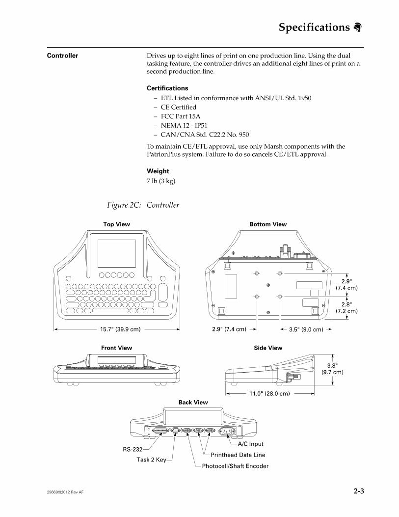
Controller
Drives up to eight lines of print on one production line. Using the dual tasking feature, the controller drives an additional eight lines of print on a second production line.
Certifications
– ETL Listed in conformance with ANSI/UL Std. 1950– CE Certified– FCC Part 15A– NEMA 12 - IP51– CAN/CNA Std. C22.2 No. 950
To maintain CE/ETL approval, use only Marsh components with the PatrionPlus system. Failure to do so cancels CE/ETL approval.
Weight
7 lb (3 kg)
Figure 2C: Controller
3.8"(9.7 cm)
2.9"(7.4 cm)
2.8"(7.2 cm)
15.7" (39.9 cm) 2.9" (7.4 cm) 3.5" (9.0 cm)
11.0" (28.0 cm)
Top View Bottom View
Front View Side View
Back View
Photocell/Shaft EncoderTask 2 Key
A/C Input
Printhead Data LineRS-232
Specifications
2-4
29669/02012 Rev AF
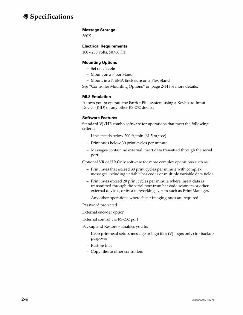
Message Storage
360K
Electrical Requirements
100 - 230 volts; 50/60 Hz
Mounting Options
– Set on a Table– Mount on a Floor Stand– Mount in a NEMA Enclosure on a Flex Stand
See “Controller Mounting Options” on page 2-14 for more details.
ML8 Emulation
Allows you to operate the PatrionPlus system using a Keyboard Input Device (KID) or any other RS-232 device.
Software Features
Standard VJ/HR combo software for operations that meet the following criteria:
– Line speeds below 200 ft/min (61.5 m/sec)
– Print rates below 30 print cycles per minute
– Messages contain no external insert data transitted through the serial port
Optional VR or HR Only software for more complex operations such as:
– Print rates that exceed 30 print cycles per minute with complex messages including variable bar codes or multiple variable data fields.
– Print rates exceed 20 print cycles per minute where insert data is transmitted through the serial port from bar code scanners or other external devices, or by a networking system such as Print Manager.
– Any other operations where faster imaging rates are required.
Password protected
External encoder option
External control via RS-232 port
Backup and Restore – Enables you to:
– Keep printhead setup, message or logo files (VJ logos only) for backup purposes
– Restore files– Copy files to other controllers
Specifications
29669/02012 Rev AF
2-5
Messages
Using a dual task key, you can create and store up to 3,000 messages. Maximum message length: 65" (165.1 cm) or 78 characters (at the default software settings 50 ft/min (15 m/min) line speed and character width 40)
– Can contain the following elements:Text (six standard fonts available for VJ printheads and five standard fonts available for HR Series printheads. Custom fonts are also available for HR Series printheads if using Keymaster software.)
– Logos– Counts– Time, date, and expiration date codes– Work shift codes– Bar codes
Invert print feature for printing messages upside down
Bold feature for printing bold messages with VJ printheads
Available Bar Codes
Bar codes printed with VJ or HR/120 printheads will not meet industry height specification standards.
Code 39Interleaved 2 of 5 (I 2 of 5)I 2 of 5 UCC/EANUPC-AEAN-13UCC/EAN-128Code 128
Specifications
2-6
29669/02012 Rev AF
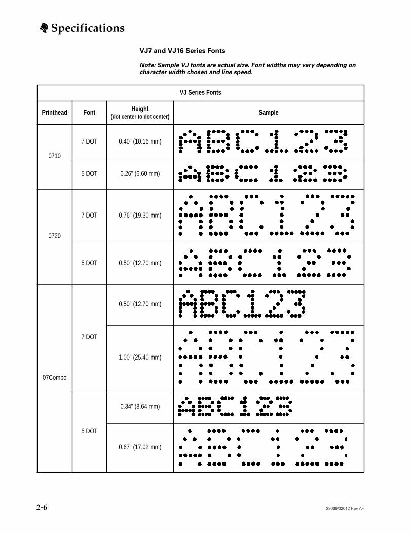
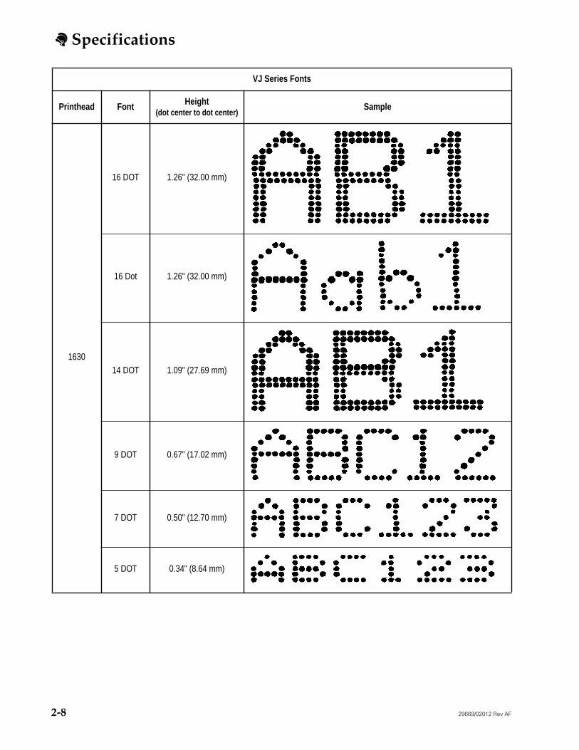
VJ7 and VJ16 Series Fonts
Note: Sample VJ fonts are actual size. Font widths may vary depending on character width chosen and line speed.
VJ Series Fonts
Printhead Font Height
(dot center to dot center)
Sample
0710
7 DOT 0.40" (10.16 mm)
5 DOT 0.26" (6.60 mm)
0720
7 DOT 0.76" (19.30 mm)
5 DOT 0.50" (12.70 mm)
07Combo
7 DOT
0.50" (12.70 mm)
1.00" (25.40 mm)
5 DOT
0.34" (8.64 mm)
0.67" (17.02 mm)
Specifications
29669/02012 Rev AF
2-7
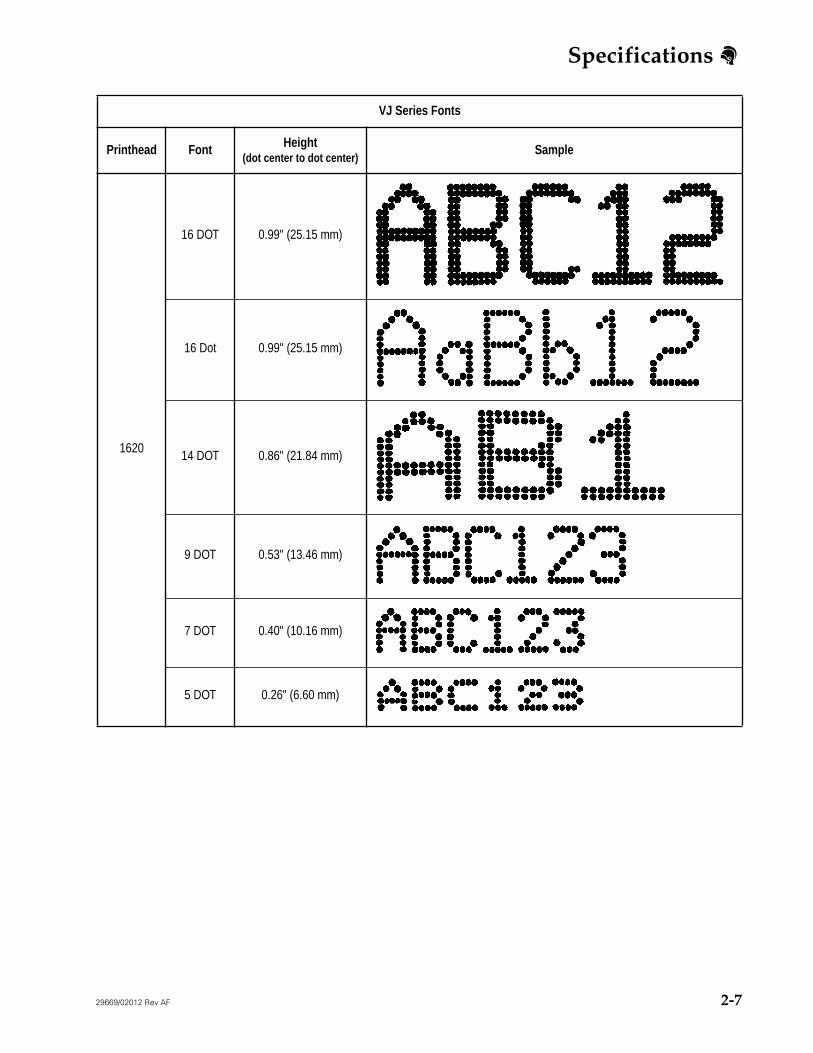
1620
16 DOT 0.99" (25.15 mm)
16 Dot 0.99" (25.15 mm)
14 DOT 0.86" (21.84 mm)
9 DOT 0.53" (13.46 mm)
7 DOT 0.40" (10.16 mm)
5 DOT 0.26" (6.60 mm)
VJ Series Fonts
Printhead Font Height
(dot center to dot center)
Sample
Specifications
2-8
29669/02012 Rev AF
1630
16 DOT 1.26" (32.00 mm)
16 Dot 1.26" (32.00 mm)
14 DOT 1.09" (27.69 mm)
9 DOT 0.67" (17.02 mm)
7 DOT 0.50" (12.70 mm)
5 DOT 0.34" (8.64 mm)
VJ Series Fonts
Printhead Font Height
(dot center to dot center)
Sample
Specifications
29669/02012 Rev AF
2-9
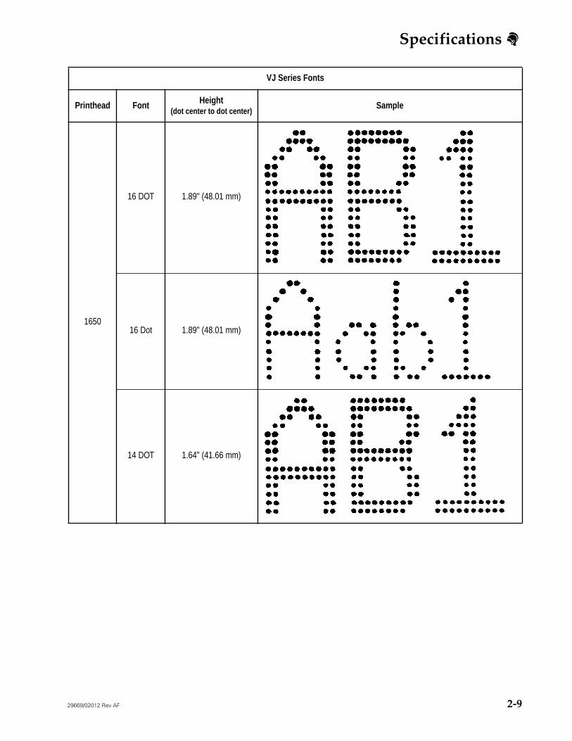
1650
16 DOT 1.89" (48.01 mm)
16 Dot 1.89" (48.01 mm)
14 DOT 1.64" (41.66 mm)
VJ Series Fonts
Printhead Font Height
(dot center to dot center)
Sample
Specifications
2-10
29669/02012 Rev AF
VJ Series Fonts
Printhead Font Height
(dot center to dot center)
Sample
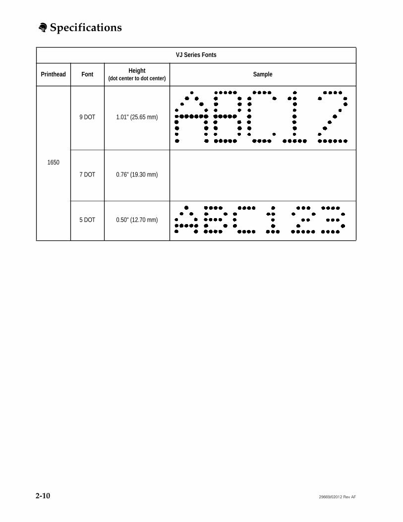
1650
9 DOT 1.01" (25.65 mm)
7 DOT 0.76" (19.30 mm)
5 DOT 0.50" (12.70 mm)
Specifications
29669/02012 Rev AF
2-11
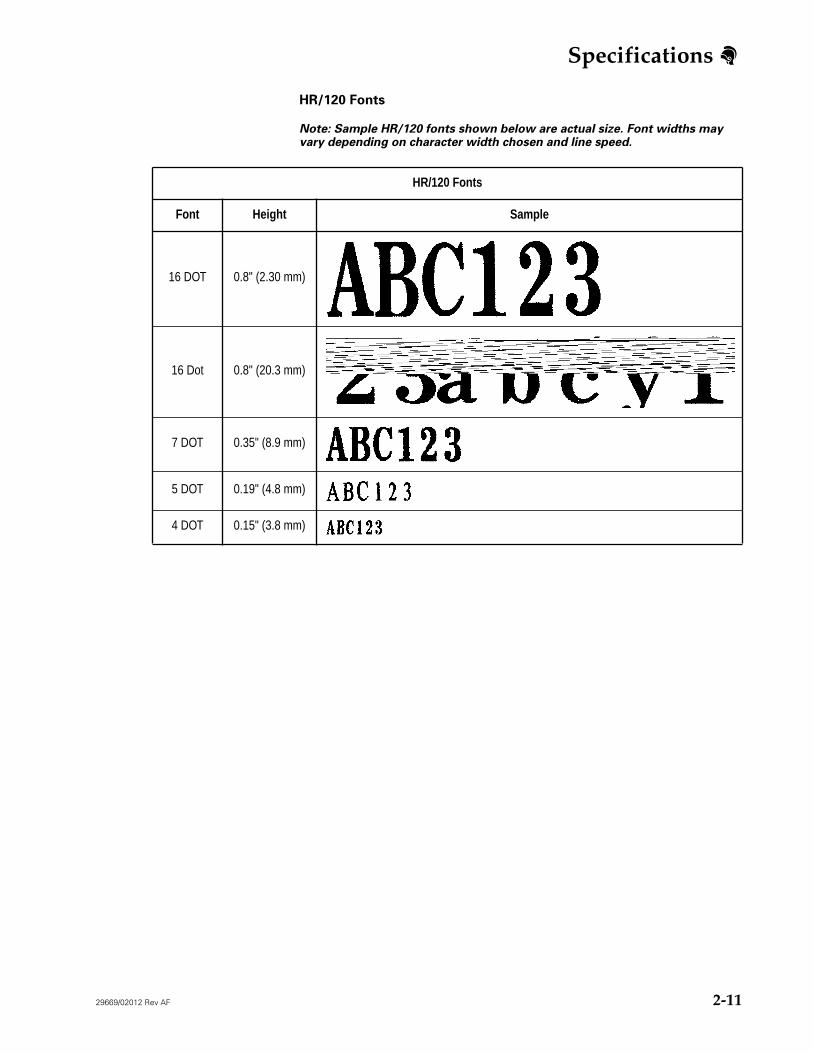
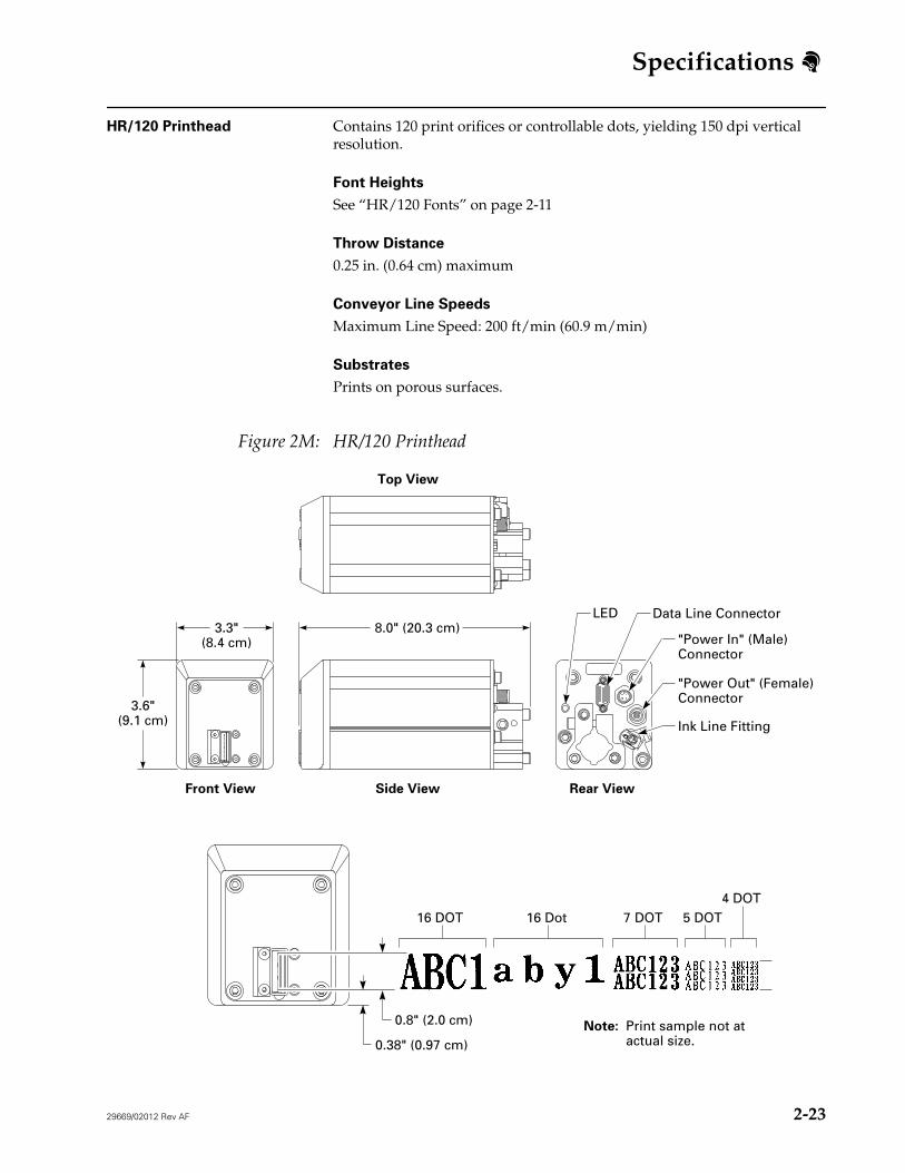
HR/120 Fonts
Note: Sample HR/120 fonts shown below are actual size. Font widths may vary depending on character width chosen and line speed.
HR/120 Fonts
Font Height Sample
16 DOT 0.8" (2.30 mm)
16 Dot 0.8" (20.3 mm)
7 DOT 0.35" (8.9 mm)
5 DOT 0.19" (4.8 mm)
4 DOT 0.15" (3.8 mm)
Specifications
2-12
29669/02012 Rev AF
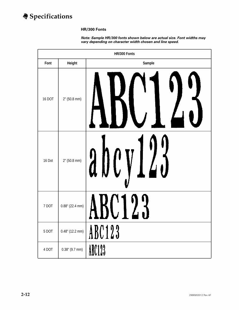
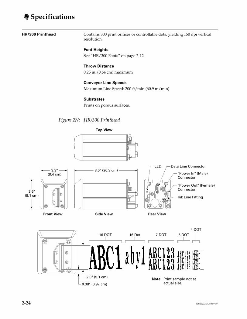
HR/300 Fonts
Note: Sample HR/300 fonts shown below are actual size. Font widths may vary depending on character width chosen and line speed.
HR/300 Fonts
Font Height Sample
16 DOT 2" (50.8 mm)
16 Dot 2" (50.8 mm)
7 DOT 0.88" (22.4 mm)
5 DOT 0.48" (12.2 mm)
4 DOT 0.38" (9.7 mm)
Specifications
29669/02012 Rev AF
2-13
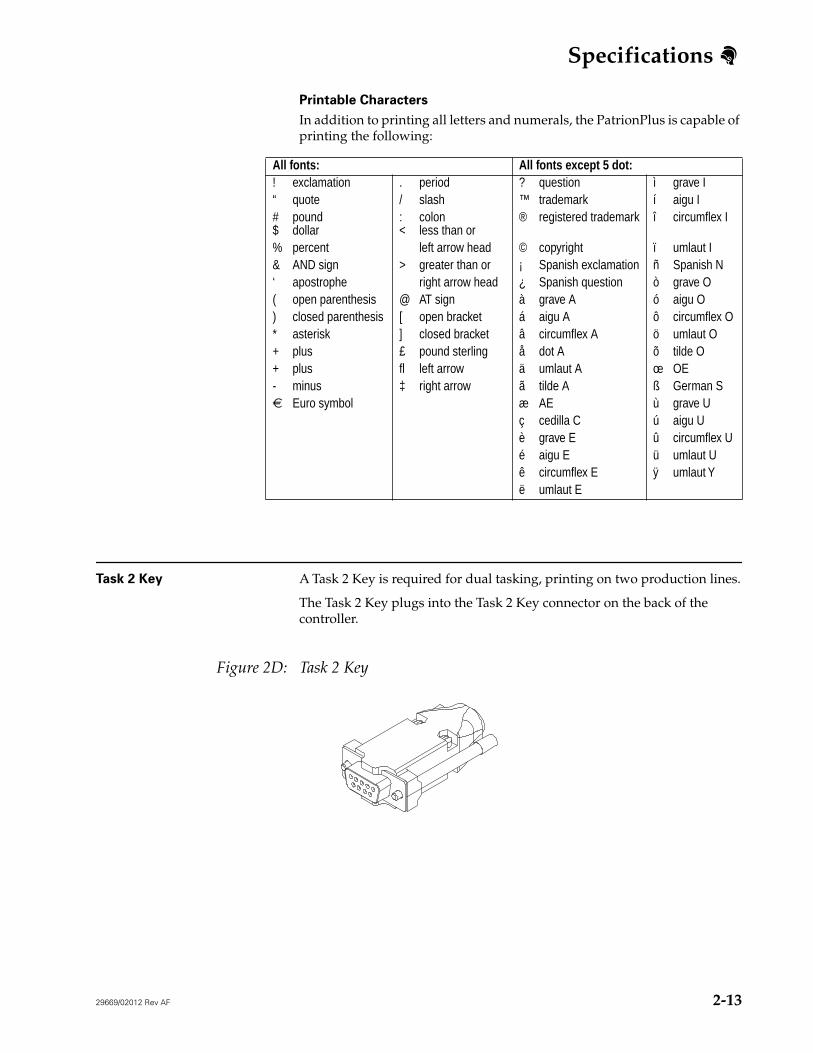
Printable Characters
In addition to printing all letters and numerals, the PatrionPlus is capable of printing the following:
Task 2 Key
A Task 2 Key is required for dual tasking, printing on two production lines.
The Task 2 Key plugs into the Task 2 Key connector on the back of the controller.
Figure 2D: Task 2 Key
All fonts: All fonts except 5 dot:
! exclamation . period ? question ì grave I“ quote / slash ™ trademark í aigu I# pound$ dollar
Euro symbol æ AE ù grave Uç cedilla C ú aigu Uè grave E û circumflex Ué aigu E ü umlaut Uê circumflex E ÿ umlaut Yë umlaut E
Specifications
2-14
29669/02012 Rev AF
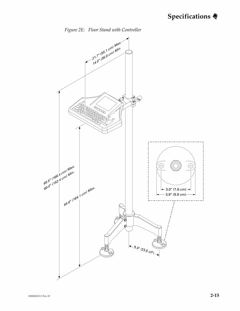
Controller Mounting Options Floor Stand Mount
Offers flexibility so the stand can be moved if you need to change your layout. The controller is attached to a tripod stand. (See Figure 2E.)
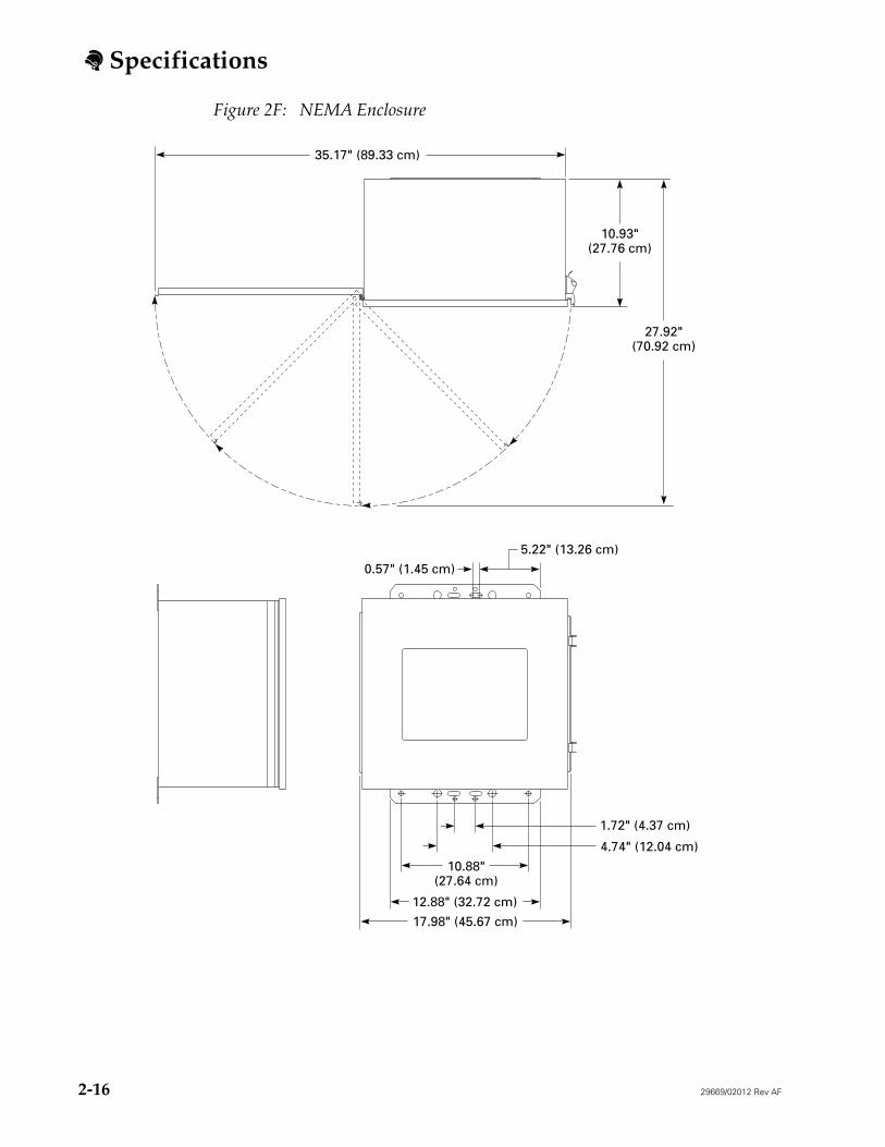
NEMA Enclosure
Provides protection against harsh environments. Mounts on a Flex Stand. (See Figure 2F.)
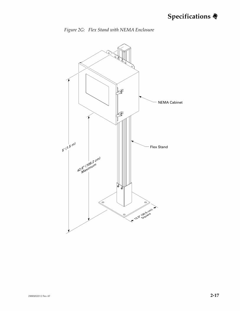
Flex Stand
Available height: 5 ft (1.5 m)
Specifications
29669/02012 Rev AF
2-15
Figure 2E: Floor Stand with Controller
3.9" (9.9 cm)3.0" (7.6 cm)
9.4" (23.9 cm)
21.7" (55.1 cm) M
ax
14.0" (35.6 cm) M
in
65.5" (166.4 cm) M
ax.
60.0" (152.4 cm) M
in.
64.6" (164.1 cm) M
ax.
Specifications
2-16
29669/02012 Rev AF
Figure 2F: NEMA Enclosure
27.92"(70.92 cm)
10.93"(27.76 cm)
35.17" (89.33 cm)
17.98" (45.67 cm)
12.88" (32.72 cm)
4.74" (12.04 cm)
1.72" (4.37 cm)
0.57" (1.45 cm)
5.22" (13.26 cm)
10.88"(27.64 cm)
Specifications
29669/02012 Rev AF 2-17
Figure 2G: Flex Stand with NEMA Enclosure
12.0" (30.5 cm)
Square
5' (1.5 m
)
42.6" (108.2 cm)
Maximum
Flex Stand
NEMA Cabinet
Specifications
2-18 29669/02012 Rev AF
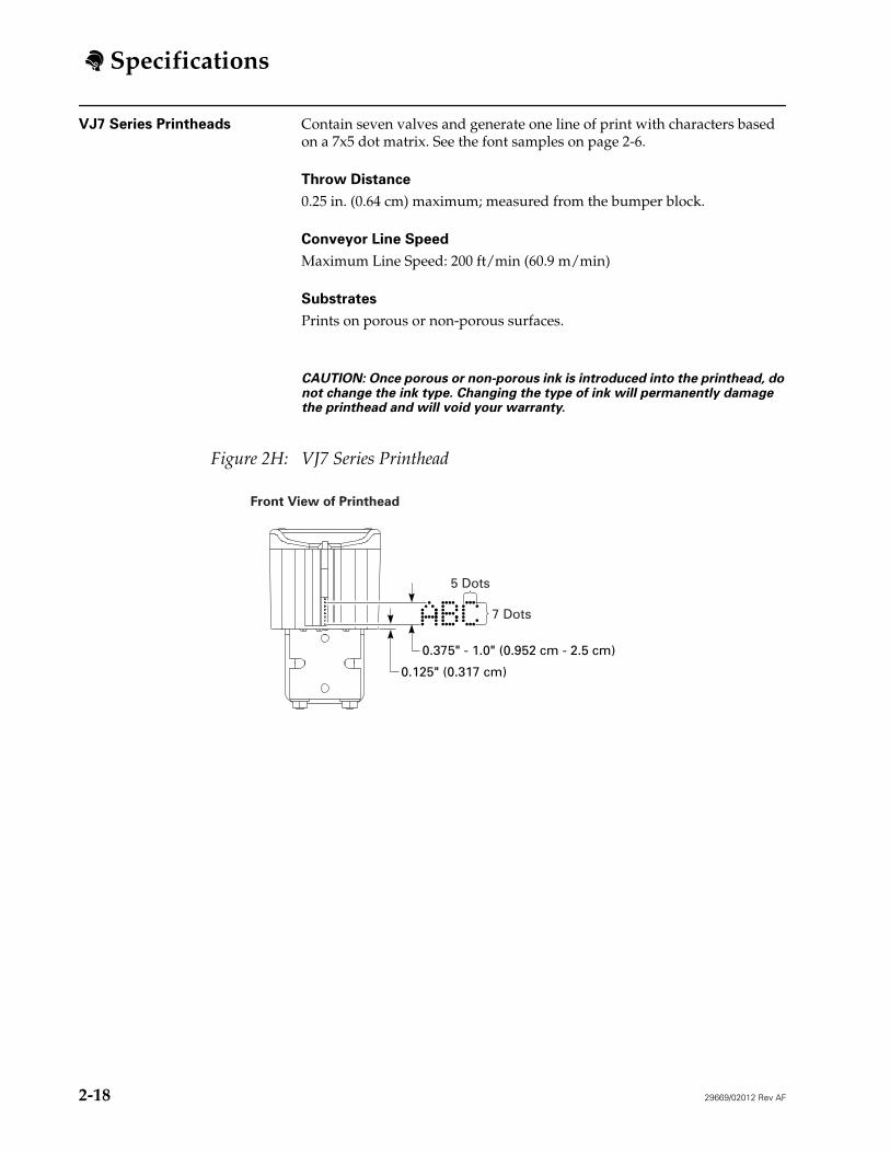
VJ7 Series Printheads Contain seven valves and generate one line of print with characters based on a 7x5 dot matrix. See the font samples on page 2-6.
Throw Distance
0.25 in. (0.64 cm) maximum; measured from the bumper block.
Conveyor Line Speed
Maximum Line Speed: 200 ft/min (60.9 m/min)
Substrates
Prints on porous or non-porous surfaces.
CAUTION: Once porous or non-porous ink is introduced into the printhead, do not change the ink type. Changing the type of ink will permanently damage the printhead and will void your warranty.
Figure 2H: VJ7 Series Printhead
5 Dots
Front View of Printhead
7 Dots
0.375" - 1.0" (0.952 cm - 2.5 cm)
0.125" (0.317 cm)
Specifications
29669/02012 Rev AF 2-19
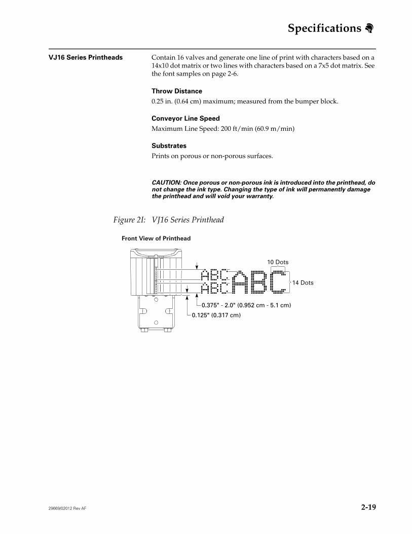
VJ16 Series Printheads Contain 16 valves and generate one line of print with characters based on a 14x10 dot matrix or two lines with characters based on a 7x5 dot matrix. See the font samples on page 2-6.
Throw Distance
0.25 in. (0.64 cm) maximum; measured from the bumper block.
Conveyor Line Speed
Maximum Line Speed: 200 ft/min (60.9 m/min)
Substrates
Prints on porous or non-porous surfaces.
CAUTION: Once porous or non-porous ink is introduced into the printhead, do not change the ink type. Changing the type of ink will permanently damage the printhead and will void your warranty.
Figure 2I: VJ16 Series Printhead
Front View of Printhead
10 Dots
14 Dots
0.375" - 2.0" (0.952 cm - 5.1 cm)
0.125" (0.317 cm)
Specifications
2-20 29669/02012 Rev AF
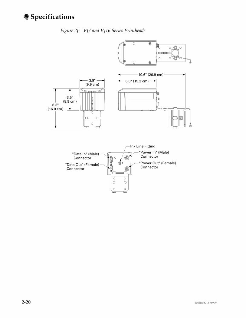
Figure 2J: VJ7 and VJ16 Series Printheads
6.3"(16.0 cm)
3.5"(8.9 cm)
3.9"(9.9 cm)
10.6" (26.9 cm)
6.0" (15.2 cm)
"Power In" (Male) Connector
"Data In" (Male) Connector
"Data Out" (Female) Connector
Ink Line Fitting
"Power Out" (Female) Connector
Specifications
29669/02012 Rev AF 2-21
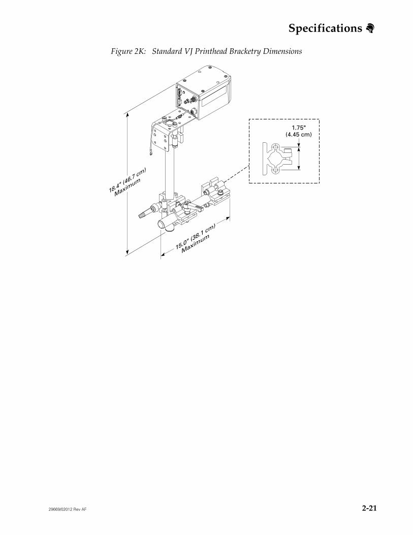
Figure 2K: Standard VJ Printhead Bracketry Dimensions
15.0" (38.1 cm)
Maximum
18.4" (46.7 cm)
Maximum
1.75"(4.45 cm)
Specifications
2-22 29669/02012 Rev AF
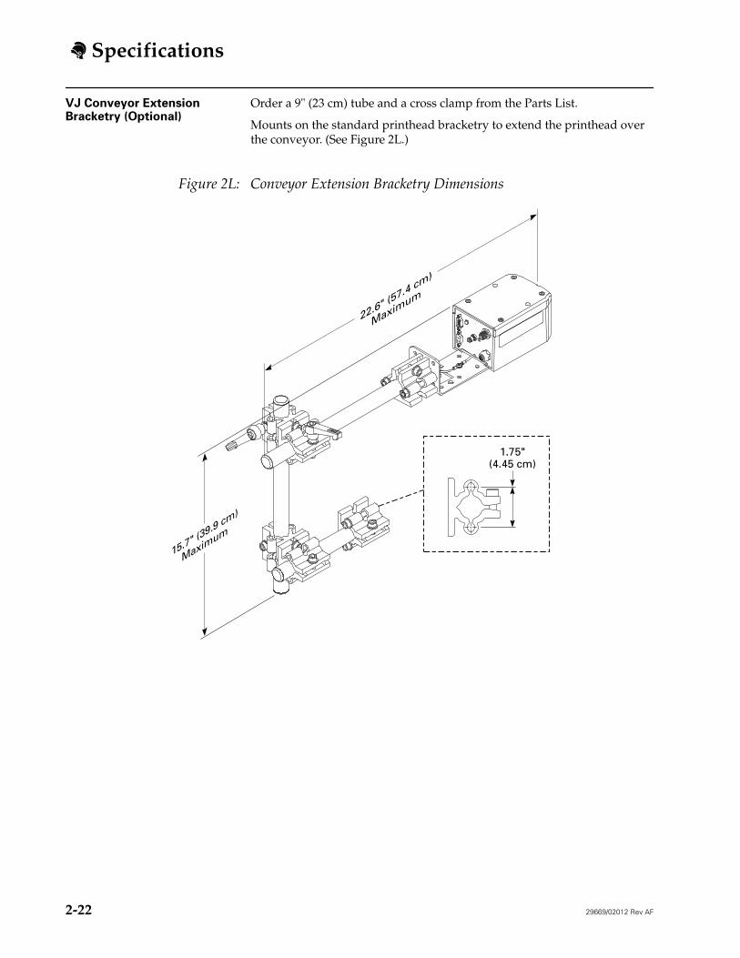
VJ Conveyor Extension Bracketry (Optional)
Order a 9" (23 cm) tube and a cross clamp from the Parts List.
Mounts on the standard printhead bracketry to extend the printhead over the conveyor. (See Figure 2L.)
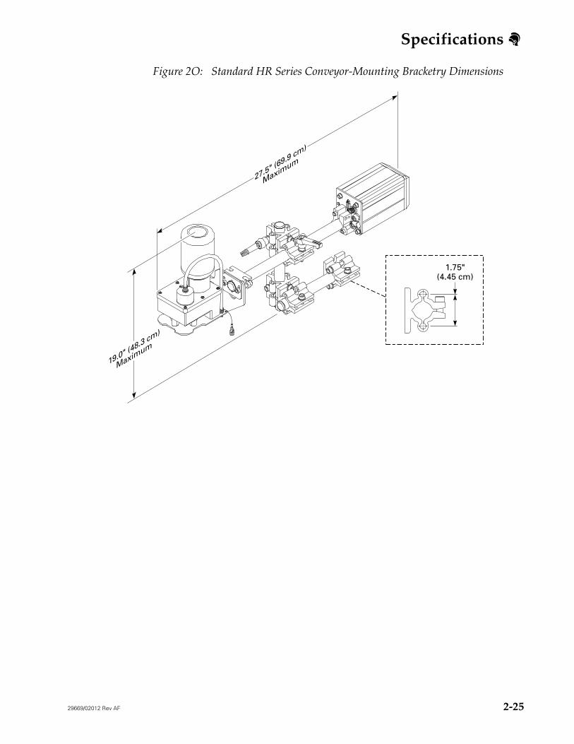
Figure 2O: Standard HR Series Conveyor-Mounting Bracketry Dimensions
27.5" (69.9 cm)
Maximum
19.0" (48.3 cm)
Maximum
1.75"(4.45 cm)
Specifications
2-26 29669/02012 Rev AF
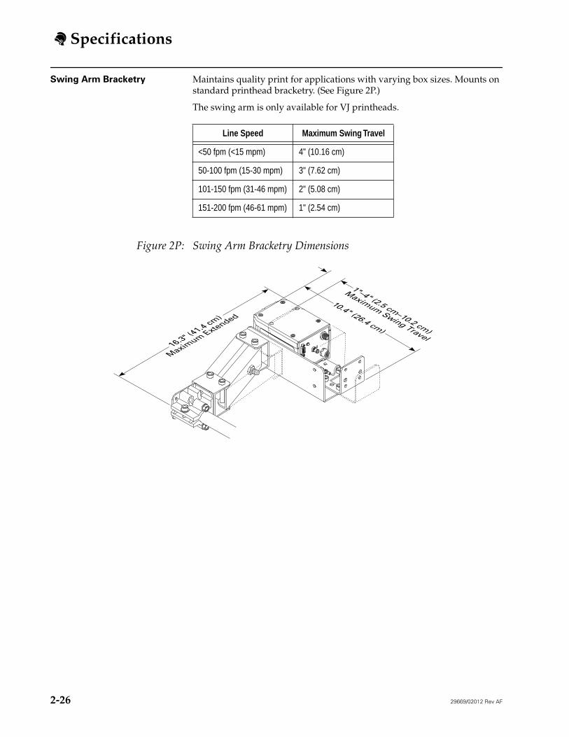
Swing Arm Bracketry Maintains quality print for applications with varying box sizes. Mounts on standard printhead bracketry. (See Figure 2P.)
The swing arm is only available for VJ printheads.
Figure 2P: Swing Arm Bracketry Dimensions
Line Speed Maximum Swing Travel
<50 fpm (<15 mpm) 4" (10.16 cm)
50-100 fpm (15-30 mpm) 3" (7.62 cm)
101-150 fpm (31-46 mpm) 2" (5.08 cm)
151-200 fpm (46-61 mpm) 1" (2.54 cm)
16.3" (41.4 cm)
Maximum Extended
10.4" (26.4 cm)
1"–4" (2.5 cm–10.2 cm)
Maximum Swing Travel
Specifications
29669/02012 Rev AF 2-27
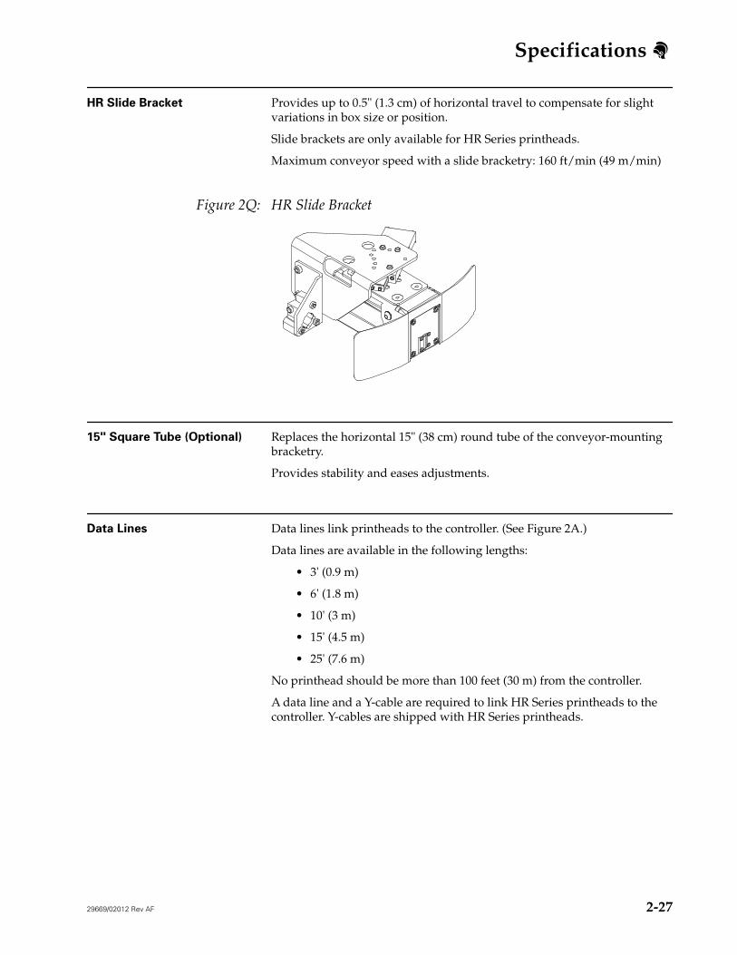
HR Slide Bracket Provides up to 0.5" (1.3 cm) of horizontal travel to compensate for slight variations in box size or position.
Slide brackets are only available for HR Series printheads.
Maximum conveyor speed with a slide bracketry: 160 ft/min (49 m/min)
Figure 2Q: HR Slide Bracket
15" Square Tube (Optional) Replaces the horizontal 15" (38 cm) round tube of the conveyor-mounting bracketry.
Provides stability and eases adjustments.
Data Lines Data lines link printheads to the controller. (See Figure 2A.)
Data lines are available in the following lengths:
• 3' (0.9 m)
• 6' (1.8 m)
• 10' (3 m)
• 15' (4.5 m)
• 25' (7.6 m)
No printhead should be more than 100 feet (30 m) from the controller.
A data line and a Y-cable are required to link HR Series printheads to the controller. Y-cables are shipped with HR Series printheads.
Specifications
2-28 29669/02012 Rev AF
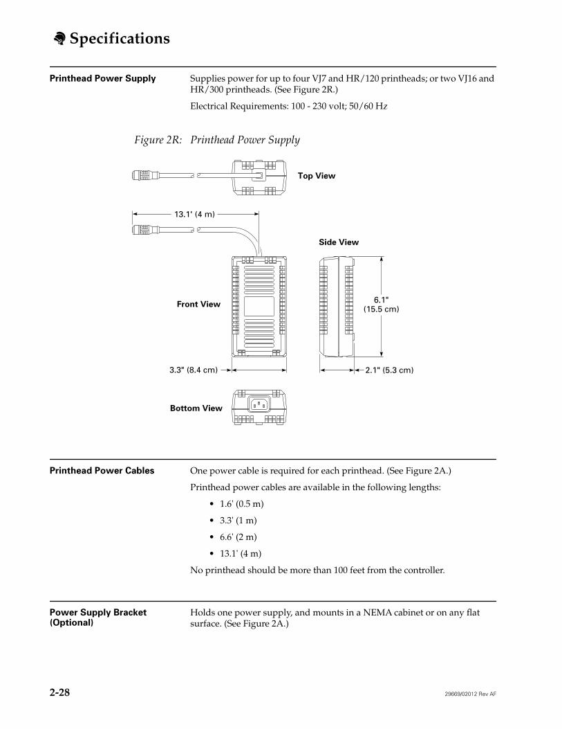
Printhead Power Supply Supplies power for up to four VJ7 and HR/120 printheads; or two VJ16 and HR/300 printheads. (See Figure 2R.)
Electrical Requirements: 100 - 230 volt; 50/60 Hz
Figure 2R: Printhead Power Supply
Printhead Power Cables One power cable is required for each printhead. (See Figure 2A.)
Printhead power cables are available in the following lengths:
• 1.6' (0.5 m)
• 3.3' (1 m)
• 6.6' (2 m)
• 13.1' (4 m)
No printhead should be more than 100 feet from the controller.
Power Supply Bracket (Optional)
Holds one power supply, and mounts in a NEMA cabinet or on any flat surface. (See Figure 2A.)
6.1"(15.5 cm)
2.1" (5.3 cm)3.3" (8.4 cm)
13.1' (4 m)
Top View
Front View
Bottom View
Side View
Specifications
29669/02012 Rev AF 2-29
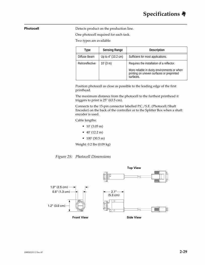
Photocell Detects product on the production line.
One photocell required for each task.
Two types are available:
Position photocell as close as possible to the leading edge of the first printhead.
The maximum distance from the photocell to the furthest printhead it triggers to print is 25" (63.5 cm).
Connects to the 15-pin connector labelled P.C./S.E. (Photocell/Shaft Encoder) on the back of the controller or to the Splitter Box when a shaft encoder is used.
Cable lengths:
• 10' (3.05 m)
• 40' (12.2 m)
• 100' (30.5 m)
Weight: 0.2 lbs (0.09 kg)
Figure 2S: Photocell Dimensions
Type Sensing Range Description
Diffuse Beam Up to 4" (10.2 cm) Sufficient for most applications.
Retroreflective 10' (3 m) Requires the installation of a reflector.
More reliable in dusty environments or when printing on uneven surfaces or preprinted surfaces.
2.1"(5.3 cm)
1.2" (3.0 cm)
0.5" (1.3 cm)
1.0" (2.5 cm)
Front View Side View
Top View
Specifications
2-30 29669/02012 Rev AF
IndependentVJ Printhead Kit (Optional)
Allows a VJ7 or VJ16 Series printhead to print without being connected to a controller.
Messages are created and the print command is sent with the controller connected to the printhead. Once printing has started, the controller can be disconnected from the printhead, and the printhead continues to print the message. Multiple independent printheads can be used.
Time, Date, and Count functions cannot be used with an independent printhead.
Kit includes a photocell board with internal photocells.
ADS Ink System The ADS ink system is capable of supplying ink for a maximum of eight lines of print, using any combination of VJ7 and VJ16 Series printheads. The ink system can withstand harsh environments and works well with high-speed applications.
Driven by compressed air:
• Minimum volume and pressure: 1 cfm at 25 psi• Maximum pressure: 150 psi• Pressure switch set to cycle on/off at 100 psi +/- 15 psi
Series 2000 Ink System One Series 2000 ink system is required for each HR Series printhead. Does not require compressed air.
Mounts on the same bracketry as the HR Series printheads.
Ink Container
16.9 oz (500 ml) ink bottle
Low Ink Beacon (Optional) Flashes red if your ink system reaches a low-ink state. (See Figure 2A.)
Mounts to a floor stand, flex stand, or any flat surface.
Ink Bottle Adapter Kit (Optional)
Allows the use of 8 oz (237 mL) Unicorn porous cartridge inks and solvent with VJ7 and VJ16 Series printheads.
Includes bracketry for installation on any flat surface and a connector assembly to connect the printhead to the ink container.
Specifications
29669/02012 Rev AF 2-31
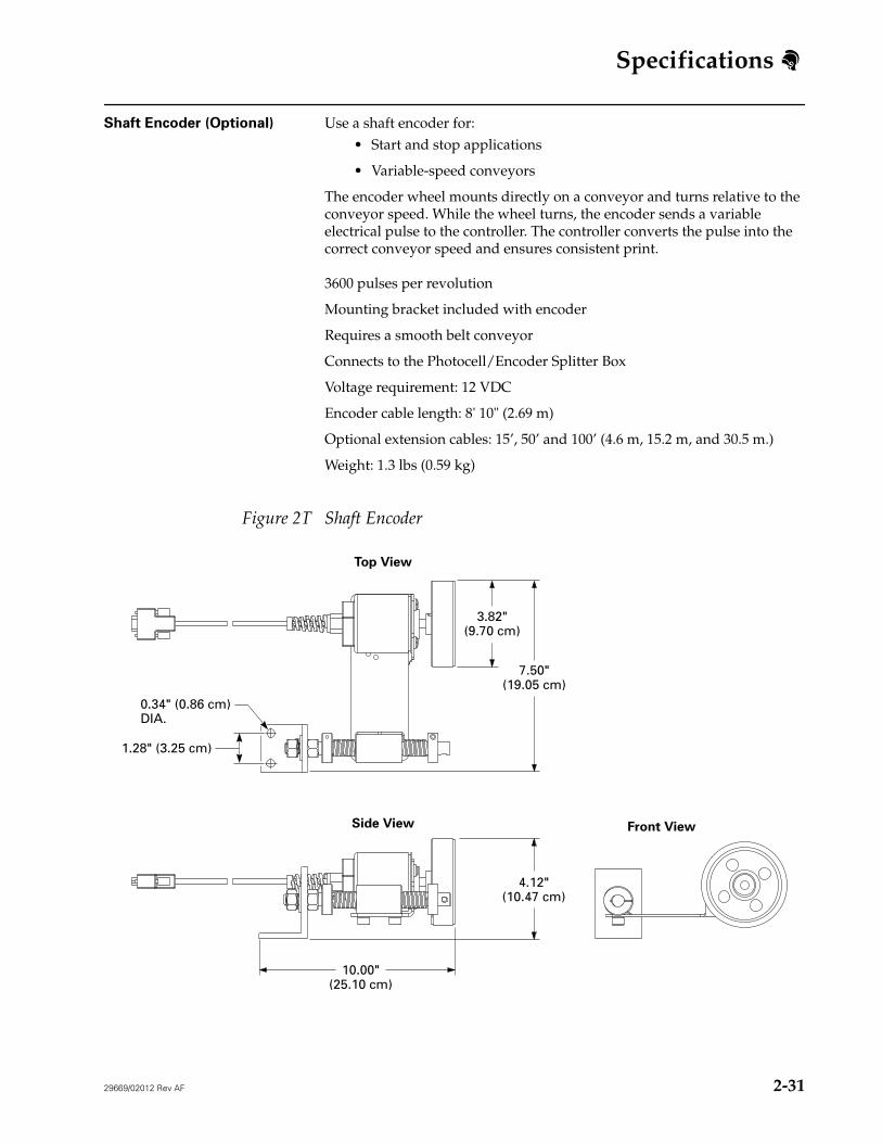
Shaft Encoder (Optional) Use a shaft encoder for:• Start and stop applications
• Variable-speed conveyors
The encoder wheel mounts directly on a conveyor and turns relative to the conveyor speed. While the wheel turns, the encoder sends a variable electrical pulse to the controller. The controller converts the pulse into the correct conveyor speed and ensures consistent print.
3600 pulses per revolution
Mounting bracket included with encoder
Requires a smooth belt conveyor
Connects to the Photocell/Encoder Splitter Box
Voltage requirement: 12 VDC
Encoder cable length: 8' 10" (2.69 m)
Optional extension cables: 15’, 50’ and 100’ (4.6 m, 15.2 m, and 30.5 m.)
Weight: 1.3 lbs (0.59 kg)
Figure 2T Shaft Encoder
4.12"(10.47 cm)
10.00"(25.10 cm)
Top View
Side View Front View
7.50"(19.05 cm)
1.28" (3.25 cm)
3.82"(9.70 cm)
0.34" (0.86 cm)DIA.
Specifications
2-32 29669/02012 Rev AF
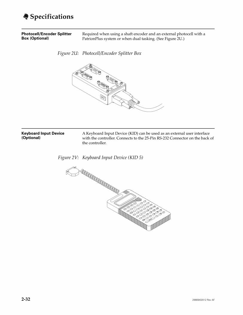
Photocell/Encoder Splitter Box (Optional)
Required when using a shaft encoder and an external photocell with a PatrionPlus system or when dual tasking. (See Figure 2U.)
Figure 2U: Photocell/Encoder Splitter Box
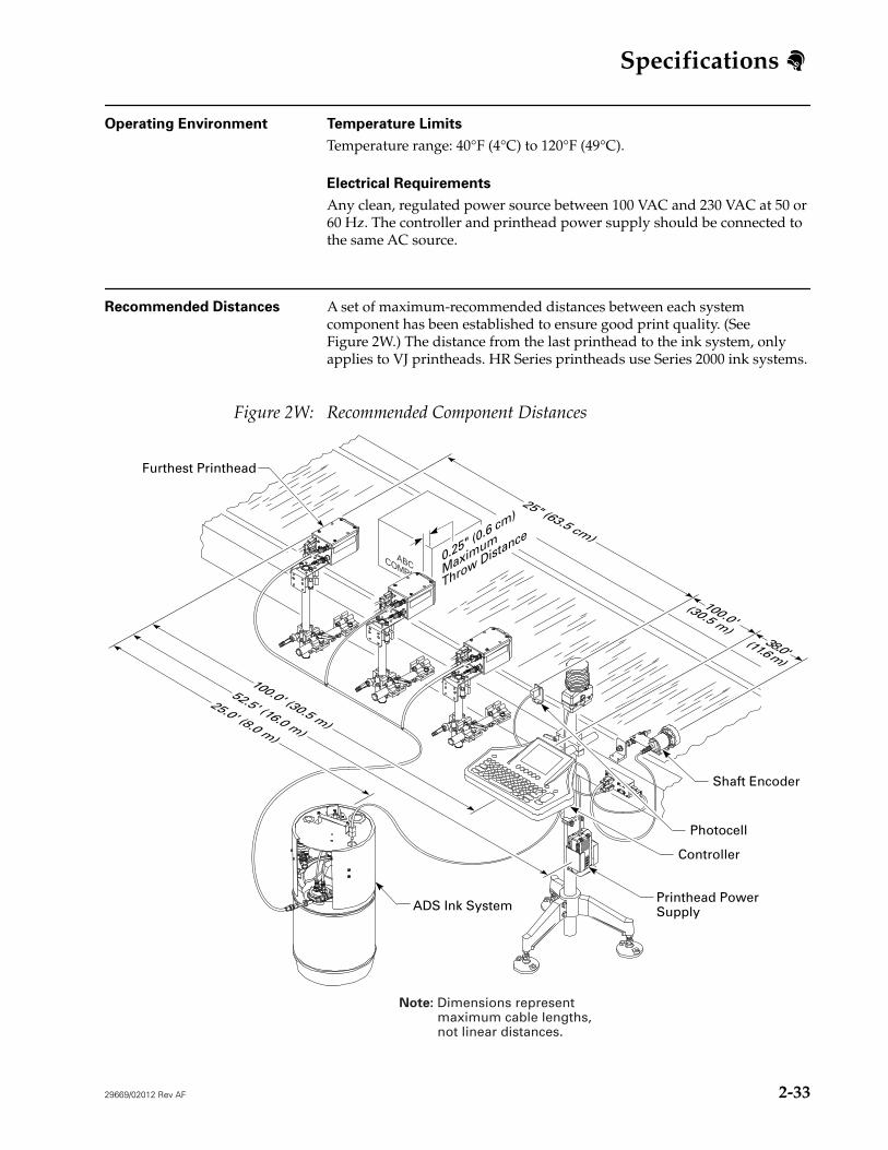
Keyboard Input Device (Optional)
A Keyboard Input Device (KID) can be used as an external user interface with the controller. Connects to the 25-Pin RS-232 Connector on the back of the controller.
Figure 2V: Keyboard Input Device (KID 5)
SE1PC
SE2PC2
INPUT
SHIFTCNTRL
WIN
WIN
E
D
A
K
J
I
H
F
Q
P
O
N
M
L
T
S
R
W
V
U
Z
Y
X
3
2
1
6
5
4
9
8
7 0
>
:
/
\
!
"
#
*
+
-
=
?
.
,
;
$
%
&
'
@
<
[
]
(
)
SPACE
Cu
Clr
Cu
Del
29669/02012 Rev AF 2-33
Specifications
Operating Environment Temperature Limits
Temperature range: 40°F (4°C) to 120°F (49°C).
Electrical Requirements
Any clean, regulated power source between 100 VAC and 230 VAC at 50 or 60 Hz. The controller and printhead power supply should be connected to the same AC source.
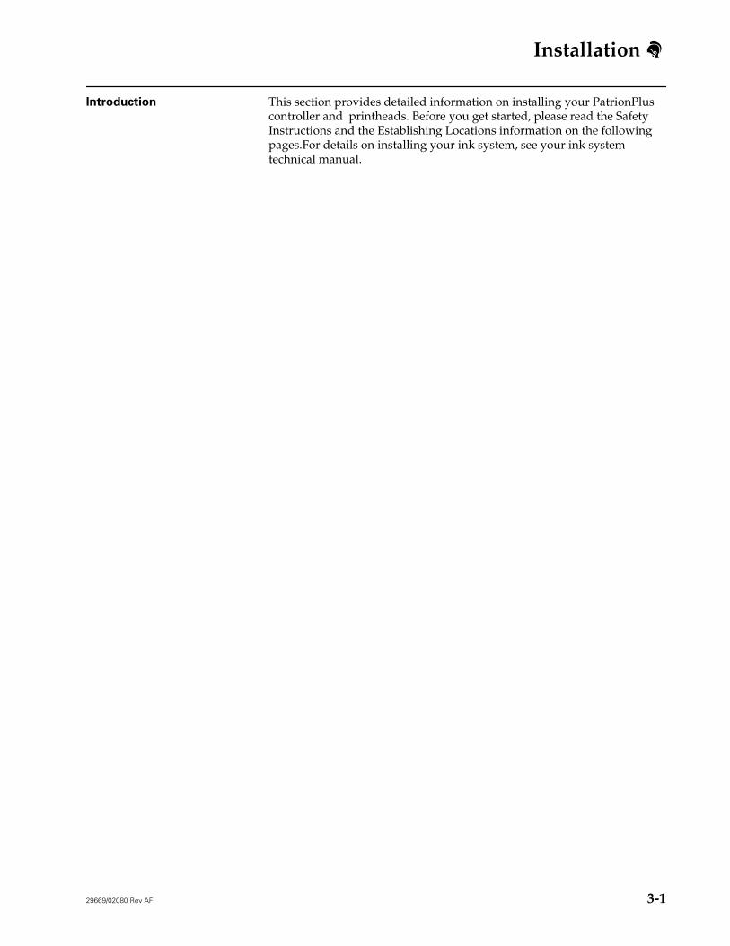
Recommended Distances A set of maximum-recommended distances between each system component has been established to ensure good print quality. (See Figure 2W.) The distance from the last printhead to the ink system, only applies to VJ printheads. HR Series printheads use Series 2000 ink systems.
Figure 2W: Recommended Component Distances
COMPANY
ABC
Controller
Shaft Encoder
Photocell
Furthest Printhead
100.0' (30.5 m)
25" (63.5 cm)
100.0'(30.5 m)
38.0'(11.6 m)
52.5' (16.0 m)
25.0' (8.0 m)
0.25" (0.6 cm)
Maximum
Throw Distance
ADS Ink SystemPrinthead PowerSupply
Note: Dimensions represent maximum cable lengths, not linear distances.
Installation
29669/02080 Rev AF i
3-Installation
Table of Contents Introduction . . . 3-1
Safety Instructions . . . 3-2
Establishing Locations . . . 3-3
Conveyor Direction . . . 3-3
Standard Printhead Bracketry Installation . . . 3-4
Introduction This section provides detailed information on installing your PatrionPlus controller and printheads. Before you get started, please read the Safety Instructions and the Establishing Locations information on the following pages.For details on installing your ink system, see your ink system technical manual.
3-
Installation
3-2 29669/02080 Rev AF
Safety Instructions WARNING: Failure to follow these safety procedures could result in personal injury and/or damage to the equipment.
Follow these safety guidelines whenever you install, service, or operate your PatrionPlus system.
• Only trained personnel should install, operate, and service the equipment.
• Always wear safety glasses with side shields, and protective gloves when working with ink or equipment containing ink.
• Always read and obey the warning decals located on equipment. Do not remove or obstruct any warning or instruction labels located on equipment.
• Always read and obey all WARNINGS and CAUTIONS in this manual.
• All electrical wiring and connections must comply with applicable local codes. Consult the appropriate regulatory agency for further information.
• Disconnect the power cord from the power source before connecting or disconnecting any cables.
• Disconnect the power cord from the power source if there is a power failure, and do not reconnect the power cord until electrical power is completely restored.
• Do not smoke near equipment.
• Operate equipment in properly ventilated areas.
• Do not pour ink or cleaning solutions into sinks, sewers, or drains. Waste disposal must comply with local regulations; contact the appropriate regulatory agency for information.
• Certain inks and cleaning solutions are flammable and must be stored appropriately. Storage must comply with local regulations; contact the appropriate regulatory agency for information. The label on the bottle or the Material Safety Data Sheet will indicate flammability.
• If ink ingestion should occur, contact a physician immediately and refer to the Material Safety Data Sheet.
Installation
29669/02080 Rev AF 3-3
Establishing Locations Before beginning installation it is important to establish locations for all system components. No printhead should be more than 100 feet (30.5 m) away from the controller. (See “Recommended Distances” on page 2-33 for details.)
Consider the following questions:
• Does the location allow for easy maintenance of the system?
• Is a power source available? The controller and power supply should be connected to the same AC outlet sourcce to ensure that power is applied to both items properly.
• If using an ADS ink system, is there an available air supply source?
• Is there adequate space for cables behind the controller?
• How long are the data lines and other cables?
• What optional equipment does the system need?
Conveyor Direction
After establishing a mounting location on the production line for your printheads, determine the conveyor direction. Stand behind the printhead to determine if the product will pass by the printhead in a right to left (Forward Print) or left to right (Reverse Print) direction. When you configure your printheads you will set the conveyor direction. (See “Printhead Configuration” on page 4-9.)
Installation
3-4 29669/02080 Rev AF
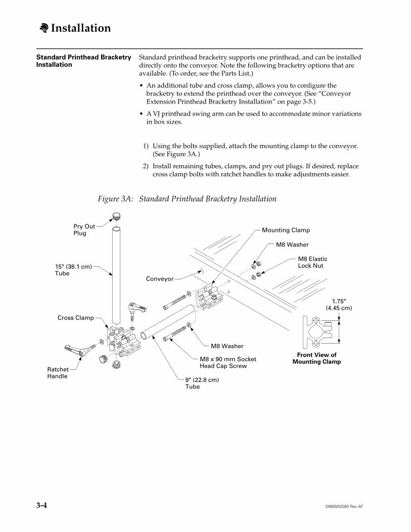
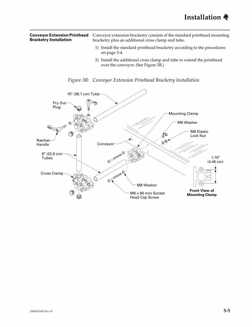
Standard Printhead Bracketry Installation
Standard printhead bracketry supports one printhead, and can be installed directly onto the conveyor. Note the following bracketry options that are available. (To order, see the Parts List.)
• An additional tube and cross clamp, allows you to configure the bracketry to extend the printhead over the conveyor. (See “Conveyor Extension Printhead Bracketry Installation” on page 3-5.)
• A VJ printhead swing arm can be used to accommodate minor variations in box sizes.
1) Using the bolts supplied, attach the mounting clamp to the conveyor. (See Figure 3A.)
2) Install remaining tubes, clamps, and pry out plugs. If desired, replace cross clamp bolts with ratchet handles to make adjustments easier.
Figure 3A: Standard Printhead Bracketry Installation
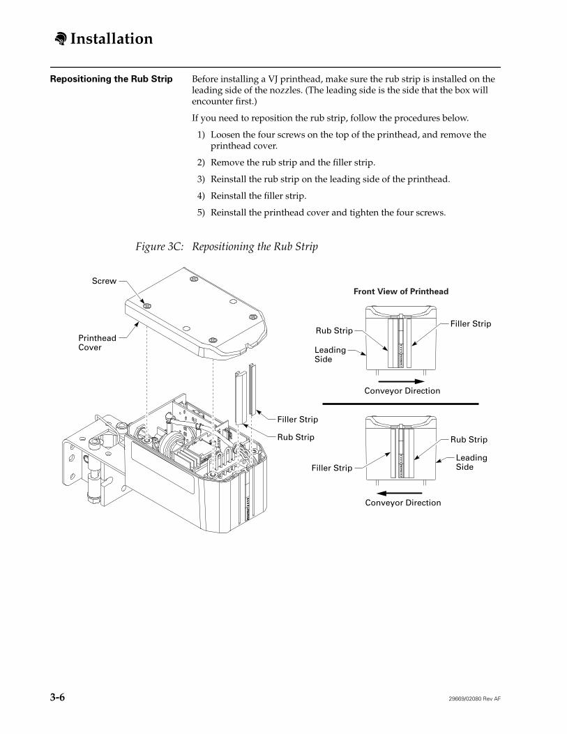
Repositioning the Rub Strip Before installing a VJ printhead, make sure the rub strip is installed on the leading side of the nozzles. (The leading side is the side that the box will encounter first.)
If you need to reposition the rub strip, follow the procedures below.
1) Loosen the four screws on the top of the printhead, and remove the printhead cover.
2) Remove the rub strip and the filler strip.
3) Reinstall the rub strip on the leading side of the printhead.
4) Reinstall the filler strip.
5) Reinstall the printhead cover and tighten the four screws.
Figure 3C: Repositioning the Rub Strip
Front View of Printhead
Rub Strip
Conveyor Direction
Conveyor Direction
Filler Strip
PrintheadCover
Screw
LeadingSide
Rub Strip
LeadingSide
Filler Strip
Rub Strip
Filler Strip
Installation
29669/02080 Rev AF 3-7
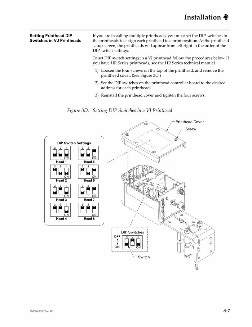
Setting Printhead DIP
Switches in VJ Printheads
If you are installing multiple printheads, you must set the DIP switches in the printheads to assign each printhead to a print position. At the printhead setup screen, the printheads will appear from left right in the order of the DIP switch settings.
To set DIP switch settings in a VJ printhead follow the procedures below. If you have HR Series printheads, see the HR Series technical manual.
1) Loosen the four screws on the top of the printhead, and remove the printhead cover. (See Figure 3D.)
2) Set the DIP switches on the printhead controller board to the desired address for each printhead.
3) Reinstall the printhead cover and tighten the four screws.
Figure 3D: Setting DIP Switches in a VJ Printhead
DIP Switch Settings
3 2 1
ONHead 1
3 2 1
ONHead 5
3 2 1
ONHead 2
3 2 1
ONHead 6
3 2 1
ON
3 2 1
ON
Head 3
3 2 1
ONHead 7
3 2 1
ONHead 4
3 2 1
ONHead 8
DIP Switches
Switch
ON
OFF
Screw
Printhead Cover
Installation
3-8 29669/02080 Rev AF
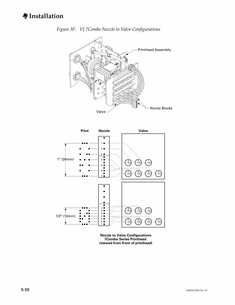
VJ 7Combo Series Printhead Adjustment
PatrionPlus VJ 7COMBO printheads can print a single line of 1/2" (13 mm) or 1" (26 mm) high characters. The printhead is shipped configured to print 1/2" (13 mm) high characters. By reconfiguring the valve tubing you can change the print height to 1" (26 mm).
If you want to reconfigure a VJ 7Combo printhead follow the procedures below.
1) If you are adjusting an existing setup, be sure to flush the printhead with solvent, turn off the controller, and disconnect the power cable and data lines.
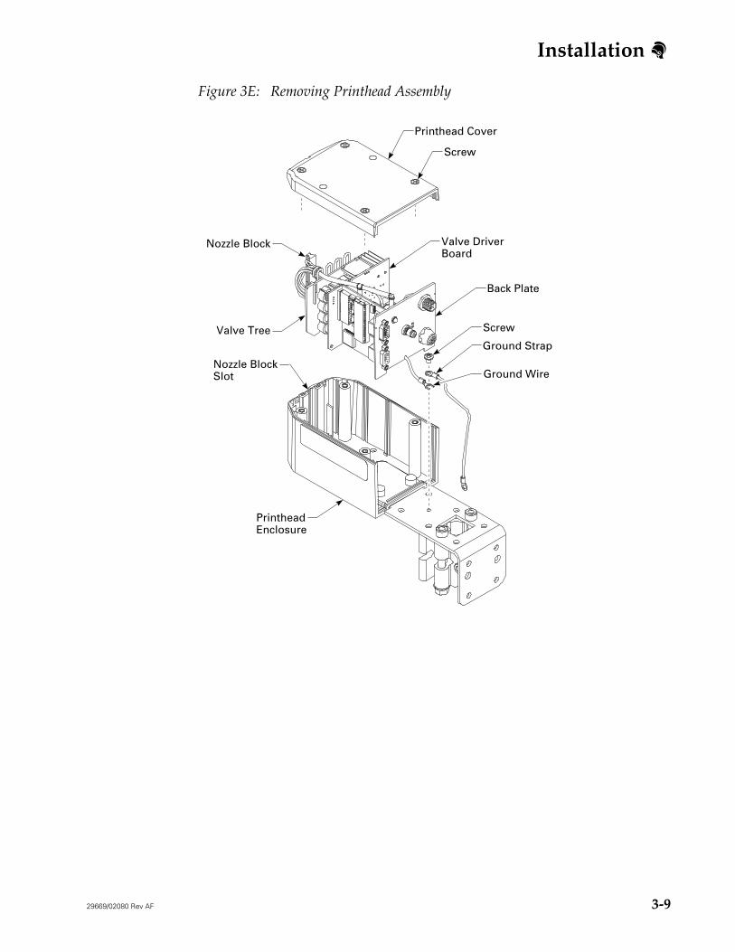
2) Disconnect the printhead ground wire from the printhead bracket. (See Figure 3E.)
3) Loosen the four screws on top of the printhead and remove the printhead cover.
4) If an independent printhead kit is installed, remove the photocell board.
5) Remove the blank nozzle blocks from the slot.
6) Lift the printhead assembly out of the printhead enclosure, being careful to simultaneously lift the nozzle blocks out of the nozzle block slot. (See Figure 3E.)
7) Carefully disconnect the valve tubing from each nozzle—one at a time—and reconnect the tubing to the appropriate new nozzle. (See Figure 3F.) Make sure the tubing is carefully aligned to prevent kinks in the tubing.
8) Replace the printhead assembly in the printhead enclosure while simultaneously installing the nozzle blocks into the slot. Nozzle blocks are keyed so there is only one way they can be put into the slot.
9) Replace the blank nozzle blocks in the slot.
10) Replace the photocell board, if an independent printhead kit was installed.
11) Reinstall the printhead cover and tighten the four screws.
12) Reconnect the printhead ground wire to the printhead bracket.
Installation
29669/02080 Rev AF 3-9
Figure 3E: Removing Printhead Assembly
Valve Driver Board
Back Plate
Screw
PrintheadEnclosure
Valve Tree
Nozzle Block
Ground Strap
Ground Wire
Screw
Printhead Cover
Nozzle BlockSlot
Installation
3-10 29669/02080 Rev AF
Figure 3F: VJ 7Combo Nozzle to Valve Configurations
Nozzle to Valve Configurations7Combo Series Printhead
(viewed from front of printhead)
Nozzle ValvePrint
Nozzle Blocks
1" (26mm)
1/2" (13mm)
Valve
Printhead Assembly
1
2
3
4
5
6
7
123
4567
1234567
123
4567
Installation
29669/02080 Rev AF 3-11
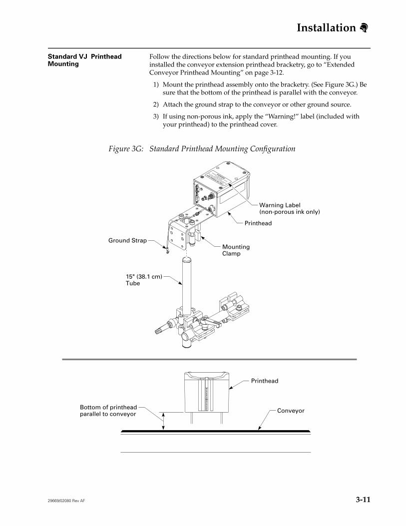
Standard VJ Printhead Mounting
Follow the directions below for standard printhead mounting. If you installed the conveyor extension printhead bracketry, go to “Extended Conveyor Printhead Mounting” on page 3-12.
1) Mount the printhead assembly onto the bracketry. (See Figure 3G.) Be sure that the bottom of the printhead is parallel with the conveyor.
2) Attach the ground strap to the conveyor or other ground source.
3) If using non-porous ink, apply the “Warning!” label (included with your printhead) to the printhead cover.
Figure 3G: Standard Printhead Mounting Configuration
WARNING!
Flammable - Vapors May Be Harmful
Contains Alcohol
Wear Safety Glasses When Servicing Equipment
(See other cautions on ink containers.)
NON POROUS INK ONLY
MountingClamp
Printhead
15" (38.1 cm)Tube
Ground Strap
Printhead
ConveyorBottom of printheadparallel to conveyor
Warning Label(non-porous ink only)
Installation
3-12 29669/02080 Rev AF
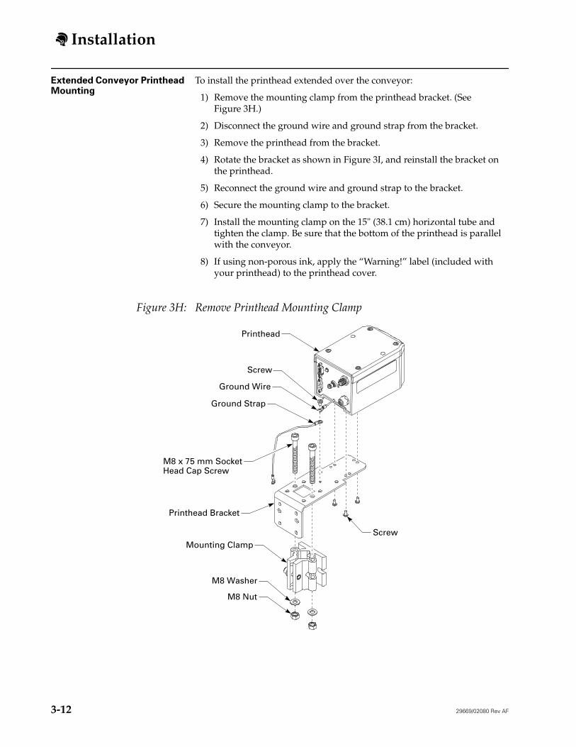
Extended Conveyor Printhead Mounting
To install the printhead extended over the conveyor:
1) Remove the mounting clamp from the printhead bracket. (See Figure 3H.)
2) Disconnect the ground wire and ground strap from the bracket.
3) Remove the printhead from the bracket.
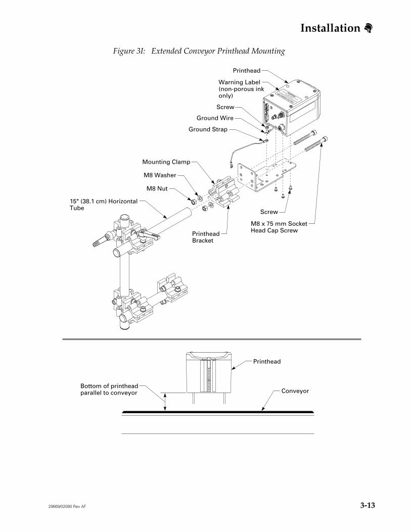
4) Rotate the bracket as shown in Figure 3I, and reinstall the bracket on the printhead.
5) Reconnect the ground wire and ground strap to the bracket.
6) Secure the mounting clamp to the bracket.
7) Install the mounting clamp on the 15" (38.1 cm) horizontal tube and tighten the clamp. Be sure that the bottom of the printhead is parallel with the conveyor.
8) If using non-porous ink, apply the “Warning!” label (included with your printhead) to the printhead cover.
Figure 3H: Remove Printhead Mounting Clamp
M8 Nut
M8 Washer
Mounting Clamp
Printhead Bracket
Ground Wire
Screw
Screw
M8 x 75 mm SocketHead Cap Screw
Ground Strap
Printhead
Installation
29669/02080 Rev AF 3-13
Figure 3I: Extended Conveyor Printhead Mounting
WARNING!
Flammable - Vapors May Be Harmful
Contains Alcohol
Wear Safety Glasses When Servicing Equipment
(See other cautions on ink containers.)
NON POROUS INK ONLY
M8 Nut
M8 Washer
Mounting Clamp
15" (38.1 cm) HorizontalTube
PrintheadBracket
Ground Wire
Screw
Screw
M8 x 75 mm SocketHead Cap Screw
Ground Strap
Printhead
Printhead
Bottom of printheadparallel to conveyor
Warning Label(non-porous inkonly)
Conveyor
Installation
3-14 29669/02080 Rev AF
ADS Ink System Installation 1) On your production line, establish a location for your ADSink systemwithin 25' (8 m) of your furthest VJ printhead and near an air supply line.
2) Install your ink system according to the instructions in your ink system technical manual.
Note: The ADS Ink System is for use with VJ printheads only.
Series 2000 Ink System Installation
Install your ink system according to the instructions in your ink system technical manual.
Unicorn Ink Bottle Adapter Kit Installation
1) On your conveyor line, establish a location for your ink bottle kit within 3' (0.9 m) of the printhead.
2) Install the ink bottle kit according to the instructions shipped with the kit.
Note: The Unicorn Ink Bottle Adapter Kit is for use with VJ printheads only.
Low Ink Beacon Installation 1) On your production line, establish a location for the beacon within 10' (3 m) of the ink system that it will connect to.
2) Install the beacon according to the instructions shipped with the beacon.
3) Connect the beacon to your ink system using the alarm beacon cable, or to multiple ink systems by using low ink alarm Y-cables.
Installation
29669/02080 Rev AF 3-15
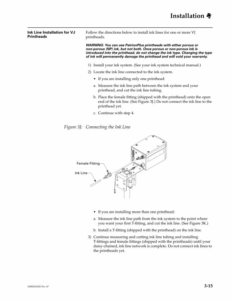
Ink Line Installation for VJ Printheads
Follow the directions below to install ink lines for one or more VJ printheads.
WARNING: You can use PatrionPlus printheads with either porous or non-porous (NP) ink, but not both. Once porous or non-porous ink is introduced into the printhead, do not change the ink type. Changing the type of ink will permanently damage the printhead and will void your warranty.
1) Install your ink system. (See your ink system technical manual.)
2) Locate the ink line connected to the ink system.
• If you are installing only one printhead:
a. Measure the ink line path between the ink system and your printhead, and cut the ink line tubing.
b. Place the female fitting (shipped with the printhead) onto the open end of the ink line. (See Figure 3J.) Do not connect the ink line to the printhead yet.
c. Continue with step 4.
Figure 3J: Connecting the Ink Line
• If you are installing more than one printhead:
a. Measure the ink line path from the ink system to the point where you want your first T-fitting, and cut the ink line. (See Figure 3K.)
b. Install a T-fitting (shipped with the printhead) on the ink line.
3) Continue measuring and cutting ink line tubing and installing T-fittings and female fittings (shipped with the printheads) until your daisy-chained, ink line network is complete. Do not connect ink lines to the printheads yet.
Female Fitting
Ink Line
Installation
3-16 29669/02080 Rev AF
4) Purge the ink line (see your ink system technical manual).
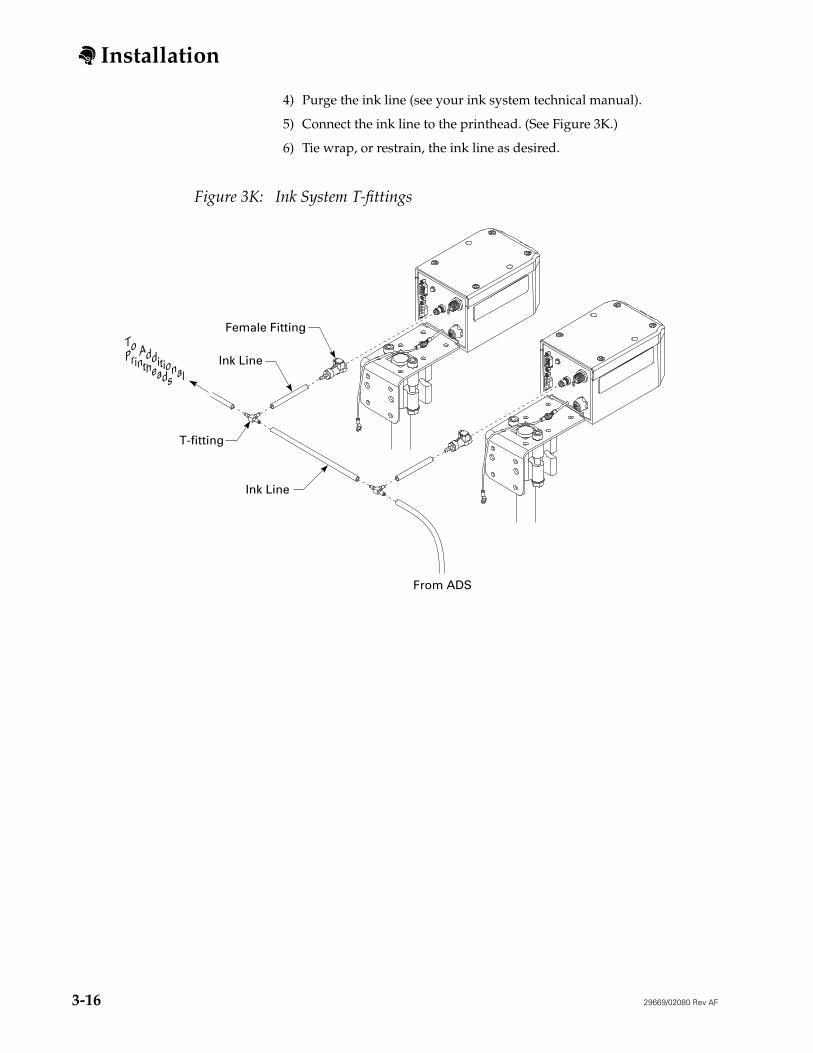
5) Connect the ink line to the printhead. (See Figure 3K.)
6) Tie wrap, or restrain, the ink line as desired.
Figure 3K: Ink System T-fittings
Female Fitting
Ink Line
Ink Line
T-fitting
From ADS
To Additional
Printheads
Installation
29669/02080 Rev AF 3-17
Power Supply and Power Cable Installation
The power supply can be mounted on a table top, on a floor stand using the power supply bracket, or in a NEMA cabinet. The power supply bracket and NEMA cabinet are available as options. Be sure you have the appropriate number of power supplies. (See “Printhead Power Supply” on page 2-28.)
1) On your production line, establish a location for the power supply. The cable routing from the power supply to the furthest printhead must be less than 52.5' (16 m).
2) Set the power supply on a table top, or using a power supply bracket:
• Mount the power supply on any flat surface
• In your PatrionPlus NEMA cabinet (see the data sheet included with the NEMA cabinet)
• Or on a floor stand (see the data sheet included with the bracket)
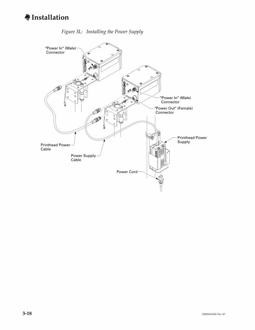
3) If you are using the power supply for more than one printhead, connect power cables to the "power out" (female) connectors on the back of all but your last printhead. (See Figure 3L.)
4) Connect all loose ends of power cables to the "power in" (male) connectors on your printheads.
5) Connect the power supply power cord to the power supply; do not yet plug it into a power source.
NOTE: After installation is complete, apply power to the printheads before plugging in the controller, or the controller may not recognize all printheads.
Power Supply Bracket For information on installing the power supply using the power supply bracket, see the instructions included with the bracket.
Installation
3-18 29669/02080 Rev AF
Figure 3L: Installing the Power Supply
Printhead PowerCable
Power SupplyCable
"Power In" (Male) Connector
Printhead PowerSupply
Power Cord
"Power In" (Male) Connector
"Power Out" (Female) Connector
Installation
29669/02080 Rev AF 3-19
Controller Mounting Configurations
Once you have established a location (see “Establishing Locations” on page 3-3), choose which mounting option is best for your application. The options are table mount, NEMA enclosure, and floor stand mount.
Table Mount
Place the controller on a level table or other surface. No extra bracketry, or hardware is required.
NEMA Enclosure
The NEMA enclosure provides protection for the controller in harsh environments. The enclosure can be mounted to a vertical surface or onto a flex stand. To mount your controller in a NEMA enclosure, follow the instructions included with the enclosure.
Floor Stand Mount
The floor stand mount offers the most flexibility because it can be moved to accommodate changes in your system layout. To mount your controller on a floor stand, follow the instructions included with the floor stand controller bracketry kit.
Installation
3-20 29669/02080 Rev AF
Data Line Installation 1) Make sure the controller and printhead power supplies are unplugged.
CAUTION: Do not connect a printhead data line while the controller or printhead power supply is plugged in. Serious damage may result to the printhead and the controller.
2) Connect a data line to the top (male) connector of your first printhead, and tighten the two thumbscrews. (See Figure 3M.)
3) Remove and retain the terminator from the Task 1 connector on the back of the controller.
4) Connect the other end of the data line to the Task 1 connector on the back of the controller.
5) To serially link the first printhead with the second, connect a data line to the bottom (female) connector of your first printhead and to the top (male) connector of your second printhead.
6) Repeat step 5 until all printheads are serially linked.
7) Install the terminator on the unused bottom (female) connector of the last printhead.
CAUTION: Proper operation cannot be guaranteed if a terminator is not installed on the unused connector.
8) If you are printing on two conveyors, install the Task 2 key on the Task 2 connector on the back of the controller.
9) Connect printheads for your second line to the Task 2 printhead connector on the back of the controller.
10) Connect the terminator included with the Task 2 key to the unused bottom (female) connector of the last printhead.
Installation
29669/02080 Rev AF 3-21
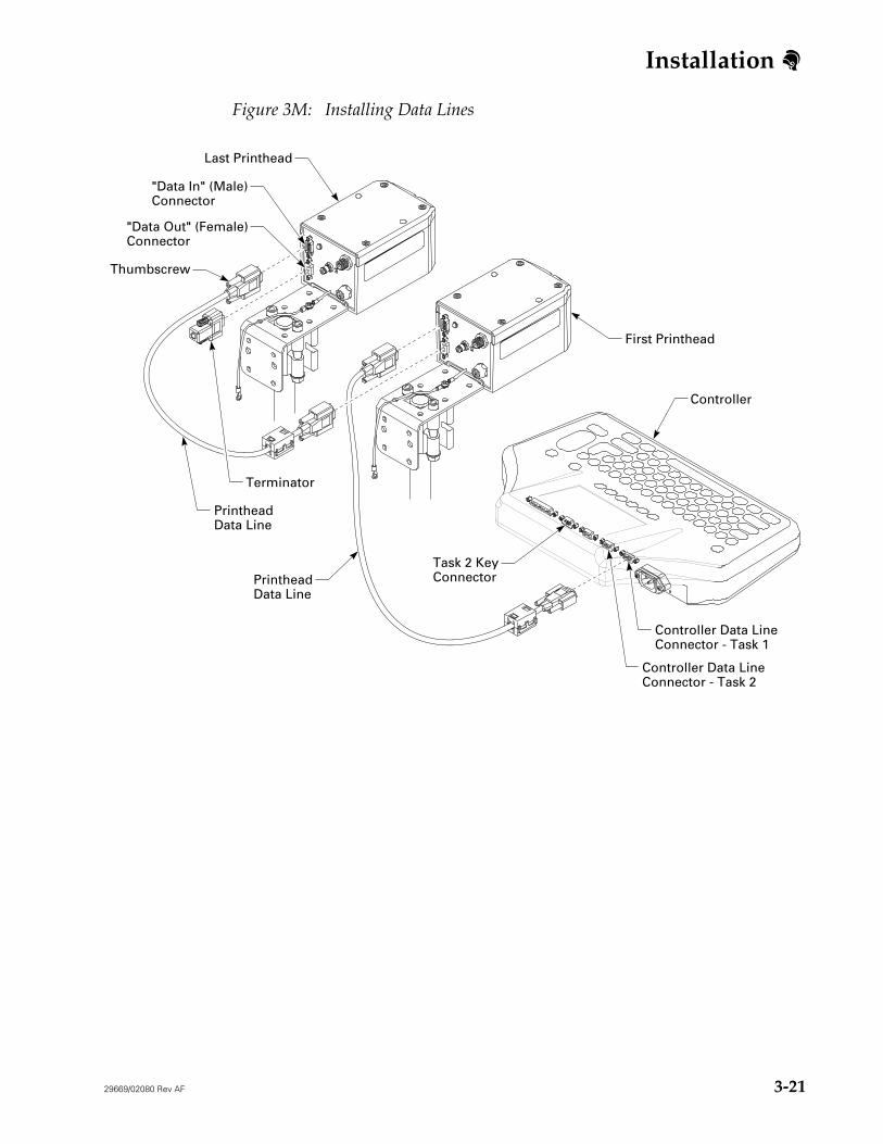
Figure 3M: Installing Data Lines
"Data In" (Male)Connector
Last Printhead
Thumbscrew
"Data Out" (Female)Connector
Controller
First Printhead
Task 2 KeyConnector
PrintheadData Line
PrintheadData Line
Controller Data LineConnector - Task 1
Controller Data LineConnector - Task 2
Terminator
Installation
3-22 29669/02080 Rev AF
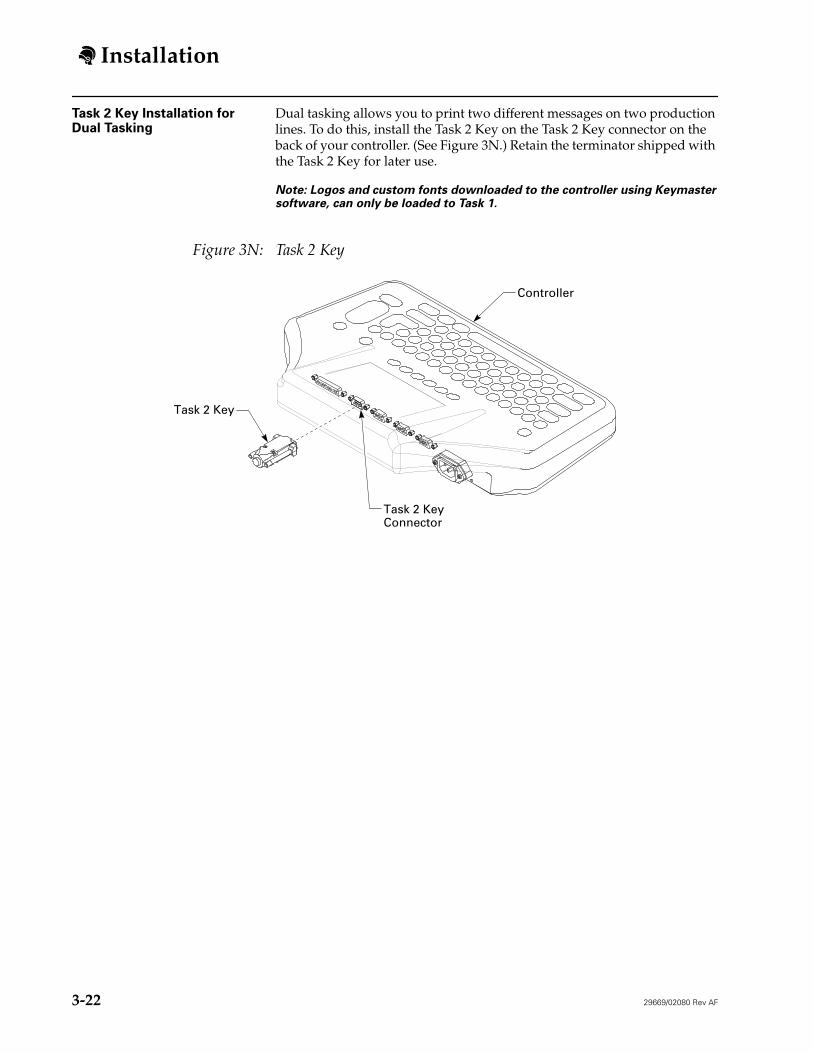
Task 2 Key Installation for Dual Tasking
Dual tasking allows you to print two different messages on two production lines. To do this, install the Task 2 Key on the Task 2 Key connector on the back of your controller. (See Figure 3N.) Retain the terminator shipped with the Task 2 Key for later use.
Note: Logos and custom fonts downloaded to the controller using Keymaster software, can only be loaded to Task 1.
Figure 3N: Task 2 Key
Controller
Task 2 KeyConnector
Task 2 Key
Installation
29669/02080 Rev AF 3-23
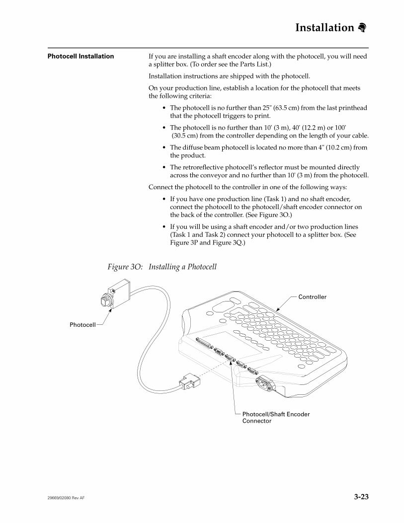
Photocell Installation If you are installing a shaft encoder along with the photocell, you will need a splitter box. (To order see the Parts List.)
Installation instructions are shipped with the photocell.
On your production line, establish a location for the photocell that meets the following criteria:
• The photocell is no further than 25" (63.5 cm) from the last printhead that the photocell triggers to print.
• The photocell is no further than 10' (3 m), 40' (12.2 m) or 100' (30.5 cm) from the controller depending on the length of your cable.
• The diffuse beam photocell is located no more than 4" (10.2 cm) from the product.
• The retroreflective photocell’s reflector must be mounted directly across the conveyor and no further than 10' (3 m) from the photocell.
Connect the photocell to the controller in one of the following ways:
• If you have one production line (Task 1) and no shaft encoder, connect the photocell to the photocell/shaft encoder connector on the back of the controller. (See Figure 3O.)
• If you will be using a shaft encoder and/or two production lines (Task 1 and Task 2) connect your photocell to a splitter box. (See Figure 3P and Figure 3Q.)
Figure 3O: Installing a Photocell
Controller
Photocell/Shaft EncoderConnector
Photocell
Installation
3-24 29669/02080 Rev AF
Shaft Encoders Use a shaft encoder when you have:
• Start-and-stop applications
• Variable line speeds
If you are installing a shaft encoder you will also need a splitter box. (To order see the Parts List.)
Installation instructions are shipped with the shaft encoder, however the installation may need to be modified due to variations in conveyor setup and product size.
Refer to the following general guidelines when installing a shaft encoder.
• Container speed must equal encoder wheel speed or the printed messages will be incorrectly aligned.
• Maintain steady contact with the moving surface that drives the encoder. If the encoder wheel bounces off the surface, it will send improper pulses to the controller.
• Keep the encoder wheel clean or it will not turn properly.
• Connect the splitter box cable to the Photocell/Shaft Encoder connector on the back of your controller. (See Figure 3Q and Figure 3R.)
• Two shaft encoders can be connected to the splitter box. (See Figure 3Q.)
Installation
29669/02080 Rev AF 3-25
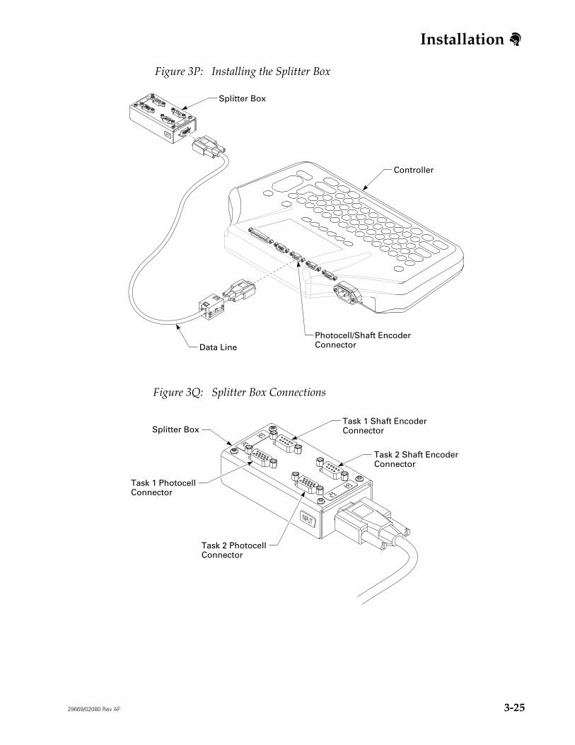
Figure 3P: Installing the Splitter Box
Figure 3Q: Splitter Box Connections
SE1PC
SE2PC2
INPUT
Controller
Splitter Box
Photocell/Shaft EncoderConnectorData Line
SE1PC
SE2PC2
INPUT
Task 1 PhotocellConnector
Task 2 PhotocellConnector
Splitter Box
Task 2 Shaft EncoderConnector
Task 1 Shaft EncoderConnector
Installation
3-26 29669/02080 Rev AF
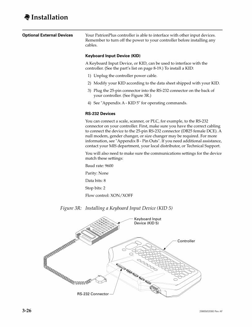
Optional External Devices Your PatrionPlus controller is able to interface with other input devices. Remember to turn off the power to your controller before installing any cables.
Keyboard Input Device (KID)
A Keyboard Input Device, or KID, can be used to interface with the controller. (See the part’s list on page 8-19.) To install a KID:
1) Unplug the controller power cable.
2) Modify your KID according to the data sheet shipped with your KID.
3) Plug the 25-pin connector into the RS-232 connector on the back of your controller. (See Figure 3R.)
4) See "Appendix A - KID 5" for operating commands.
RS-232 Devices
You can connect a scale, scanner, or PLC, for example, to the RS-232 connector on your controller. First, make sure you have the correct cabling to connect the device to the 25-pin RS-232 connector (DB25 female DCE). A null modem, gender changer, or size changer may be required. For more information, see "Appendix B - Pin Outs". If you need additional assistance, contact your MIS department, your local distributor, or Technical Support.
You will also need to make sure the communications settings for the device match these settings:
Baud rate: 9600
Parity: None
Data bits: 8
Stop bits: 2
Flow control: XON/XOFF
Figure 3R: Installing a Keyboard Input Device (KID 5)
SHIFTCNTRL
WIN
WIN
E
D
A
K
J
I
H
F
Q
P
O
N
M
L
T
S
R
W
V
U
Z
Y
X
3
2
1
6
5
4
9
8
7
0
>
:
/
\!
"
#
*
+
-
=
?
.
,
;
$
%
&
'
@
<[
]
(
)
SPACECu
ClrCu
Del
Controller
Keyboard InputDevice (KID 5)
RS-232 Connector
Installation
29669/02080 Rev AF 3-27
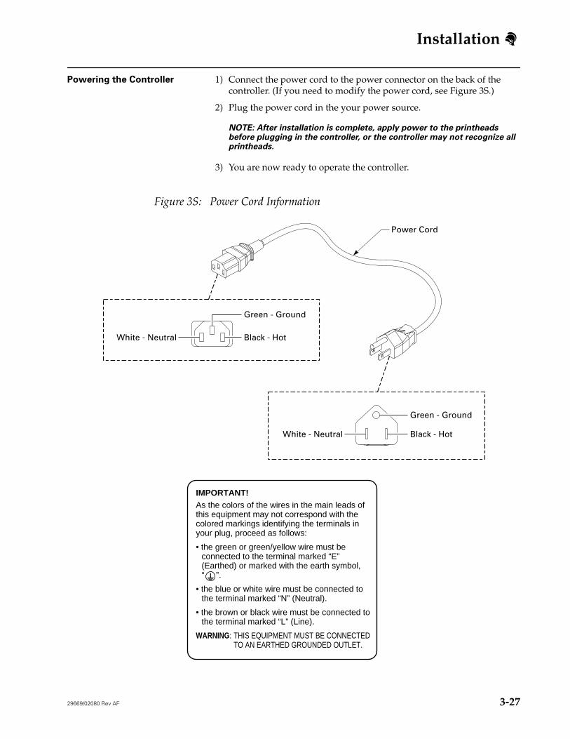
Powering the Controller 1) Connect the power cord to the power connector on the back of the controller. (If you need to modify the power cord, see Figure 3S.)
2) Plug the power cord in the your power source.
NOTE: After installation is complete, apply power to the printheads before plugging in the controller, or the controller may not recognize all printheads.
3) You are now ready to operate the controller.
Figure 3S: Power Cord Information
IMPORTANT!As the colors of the wires in the main leads of this equipment may not correspond with the colored markings identifying the terminals in your plug, proceed as follows:
• the green or green/yellow wire must be connected to the terminal marked “E” (Earthed) or marked with the earth symbol, “ ”.
• the blue or white wire must be connected to the terminal marked “N” (Neutral).
• the brown or black wire must be connected to the terminal marked “L” (Line).
WARNING: THIS EQUIPMENT MUST BE CONNECTEDTO AN EARTHED GROUNDED OUTLET.
Green - Ground
Black - HotWhite - Neutral
Green - Ground
Black - HotWhite - Neutral
Power Cord
Operation
29669/02080 Rev AG i
4-Operation
Table of Contents Overview . . . 4-1
Function Keys . . . 4-1
Arrow Keys . . . 4-1
Print Key . . . 4-1
Escape Key . . . 4-1
Backspace/Delete Key . . . 4-1
Contrast Key . . . 4-2
Screens . . . 4-2
Home Screen . . . 4-2
Message Screen . . . 4-2
Software Menu Map . . . 4-3
Controller Set Up . . . 4-4
Changing the Language . . . 4-4
Turning the Keypad Beeper Off and On . . . 4-5
Using the Screen Saver . . . 4-5
Setting Security . . . 4-6
Turning Security On or Off . . . 4-6
Putting the Controller in Logoff Mode . . . 4-7
Accessing All Functions While Security is Enabled . . . 4-7
Changing the Password . . . 4-8
Printhead Configuration . . . 4-9
Dual Tasking . . . 4-9
Printhead Setup . . . 4-9
Configuring Printheads . . . 4-11
Specifying Inverted Print . . . 4-13
Designating a Master Printhead . . . 4-14
Setting the Print Trigger . . . 4-15
Adding a Shaft Encoder to the Printhead Configuration . . . 4-16
System Set Up . . . 4-17
Setting the Time and Date . . . 4-17
Setting the Rollover Hour . . . 4-18
Setting the Alpha Codes . . . 4-19
Alpha Hour . . . 4-20
Alpha Day . . . 4-21
Alpha Date . . . 4-22
Alpha Month . . . 4-23
Setting the Work Shifts . . . 4-24
Operation
ii 29669/02080 Rev AG
Creating a Message . . . 4-25
Selecting a Font . . . 4-26
Selecting the Bold Option . . . 4-27
Adding or Editing Text . . . 4-27
Adding a Special Character . . . 4-28
Adding or Editing a Time, Date, Expiration, or Work Shift Code . . . 4-29
Adding or Editing a Product Count . . . 4-34
Adding a Logo . . . 4-39
Adding a User Insert . . . 4-40
Adding an RS-232 Insert . . . 4-41
Adding a Bar Code . . . 4-43
Print Preview . . . 4-43
Saving a Message . . . 4-44
Verifying Message Setup . . . 4-45
Changing the Character Width . . . 4-46
Adjusting the Print Position . . . 4-47
Message Options . . . 4-48
Viewing a Saved Message . . . 4-48
Deleting a Message . . . 4-49
Reverting in a Message . . . 4-50
Quitting a Message . . . 4-50
Editing a Message . . . 4-51
Opening a Message to Edit . . . 4-51
Adding an Element . . . 4-52
Selecting and Highlighting an Element . . . 4-52
Editing an Element . . . 4-52
Moving an Element . . . 4-52
Deleting an Element . . . 4-52
Viewing RS-232 Inserts and Changing Offsets . . . 4-53
Printing a Message . . . 4-54
Adjusting Product Counts While Printing . . . 4-55
Editing the Currently Printing Message . . . 4-56
Editing User Inserts . . . 4-57
Editing RS-232 Inserts and Changing Offsets . . . 4-58
Bar Codes . . . 4-59
Building a Bar Code . . . 4-59
Adding a Count Into a Bar Code . . . 4-63
Adding an Insert Into a Bar Code . . . 4-64
Building a UCC/EAN-128 Bar Code . . . 4-65
Operation
29669/02080 Rev AG iii
Advanced Features . . . 4-67
Keypad Shortcuts . . . 4-67
Hot-Keys . . . 4-68
ML8 Emulation . . . 4-70
Using an External Device . . . 4-71
Accessing DOS . . . 4-72
Backing up PH Setup, Messages, and Logos to a Computer . . . 4-73
Restoring PH Setup, Messages, and Logos . . . 4-75
Creating and Downloading a Logo . . . 4-77
29669/02080 Rev AG 4-1
Operations
Overview
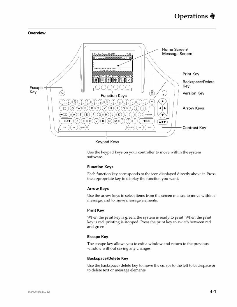
Use the keypad keys on your controller to move within the system software.
Function Keys
Each function key corresponds to the icon displayed directly above it. Press the appropriate key to display the function you want.
Arrow Keys
Use the arrow keys to select items from the screen menus, to move within a message, and to move message elements.
Print Key
When the print key is green, the system is ready to print. When the print key is red, printing is stopped. Press the print key to switch between red and green.
Escape Key
The escape key allows you to exit a window and return to the previous window without saving any changes.
Backspace/Delete Key
Use the backspace/delete key to move the cursor to the left to backspace or to delete text or message elements.
Enter
OptionOption AltAlt CtrlCtrl
Tab
Esc
CapsLock
ShiftShift
A
%5
*8
(9
)0
+=
}]
{[
:;
"'
?/
>.
<,
\_-
&7
^6
$4
!1
~`
#3
@2
Q W E
V
K
PO
L
IUYT
G H J
MNB
R
F
C
DS
XZ
Keypad Keys
Function Keys
Home Screen/Message Screen
EscapeKey
Print Key
Backspace/DeleteKey
Contrast Key
Arrow Keys
Version Key
4-
Operations
4-2 29669/02080 Rev AG
Contrast Key
Use the contrast key to adjust the brightness of your controller display.
Screens
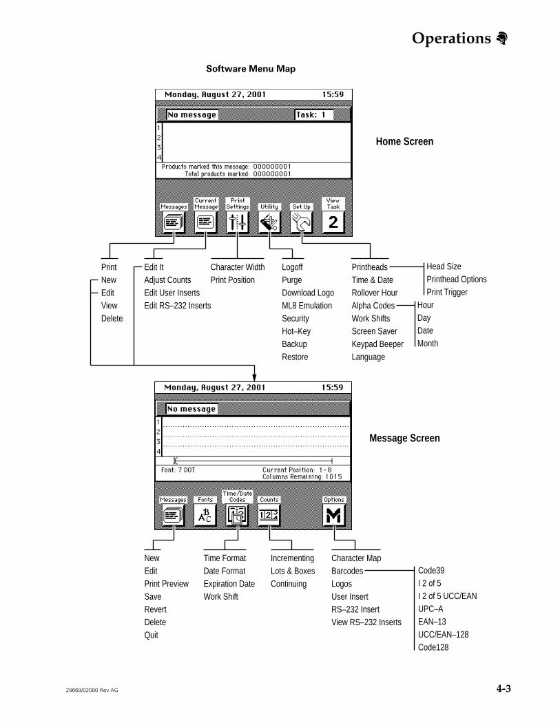
All actions begin from either the home screen or the message screen. (See “Software Menu Map” on page 4-3.)
Home Screen
The home screen is displayed at startup. You must be at the home screen to print a message. If a message was loaded to print during the last use of the controller, that message is displayed. If not, the screen appears empty. From the home screen you can access the message screen or select other functions by pressing the appropriate function key.
Access the home screen from the message screen by doing one of the following:
• Press Esc on the keypad, or
• Press Messages and select Quit.
Message Screen
You will create, edit, and save messages at the message screen. Note: the message screen is not accessible if the controller is set in logoff mode.
Access the message screen from the home screen by doing one of the following:
Edit ItAdjust CountsEdit User InsertsEdit RS–232 Inserts
PrintNewEditViewDelete
Message Screen
Character MapBarcodesLogosUser InsertRS–232 InsertView RS–232 Inserts
IncrementingLots & BoxesContinuing
Time FormatDate FormatExpiration DateWork Shift
NewEditPrint PreviewSaveRevertDeleteQuit
Head SizePrinthead OptionsPrint Trigger
HourDayDateMonth
Code39I 2 of 5I 2 of 5 UCC/EANUPC–AEAN–13UCC/EAN–128Code128
Operations
4-4 29669/02080 Rev AG
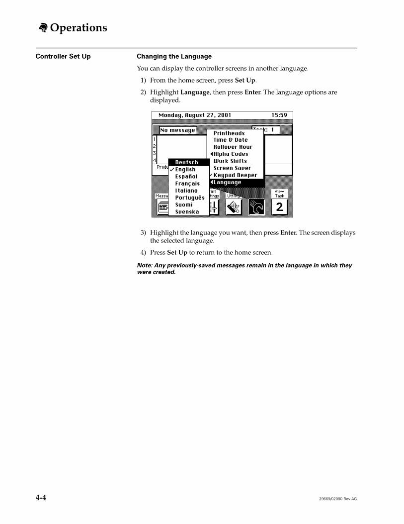
Controller Set Up Changing the Language
You can display the controller screens in another language.
1) From the home screen, press Set Up.
2) Highlight Language, then press Enter. The language options are displayed.
3) Highlight the language you want, then press Enter. The screen displays the selected language.
4) Press Set Up to return to the home screen.
Note: Any previously-saved messages remain in the language in which they were created.
Operations
29669/02080 Rev AG 4-5
Turning the Keypad Beeper Off and On
Each time a key on the controller keypad is pressed, the controller beeps to signal that the key is responding correctly. The beeper feature can be turned on and off.
To turn the keypad beeper on and off:
1) From the home screen, press Set Up.
2) Highlight Keypad Beeper, then press Enter. A check mark next to the option indicates that the Beeper is on.
3) Press Set Up to close the menu.
Using the Screen Saver
Use the Screen Saver function to extend the life of the screen display backlight. If screen saver is on, the screen display will shut off whenever the keypad is inactive for approximately 10 minutes. To light the display again, press any key.
To turn the screen saver on and off:
1) From the home screen, press Set Up.
2) Highlight Screen Saver, then press Enter. A check mark next to the option indicates that the Screen Saver is on.
3) Press Set Up to close the menu.
Operations
4-6 29669/02080 Rev AG
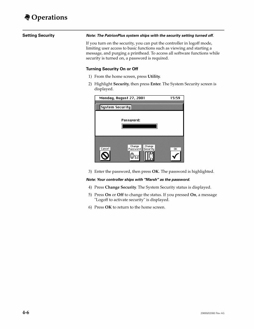
Setting Security Note: The PatrionPlus system ships with the security setting turned off.
If you turn on the security, you can put the controller in logoff mode, limiting user access to basic functions such as viewing and starting a message, and purging a printhead. To access all software functions while security is turned on, a password is required.
Turning Security On or Off
1) From the home screen, press Utility.
2) Highlight Security, then press Enter. The System Security screen is displayed.
3) Enter the password, then press OK. The password is highlighted.
Note: Your controller ships with "Marsh" as the password.
4) Press Change Security. The System Security status is displayed.
5) Press On or Off to change the status. If you pressed On, a message "Logoff to activate security" is displayed.
6) Press OK to return to the home screen.
Operations
29669/02080 Rev AG 4-7
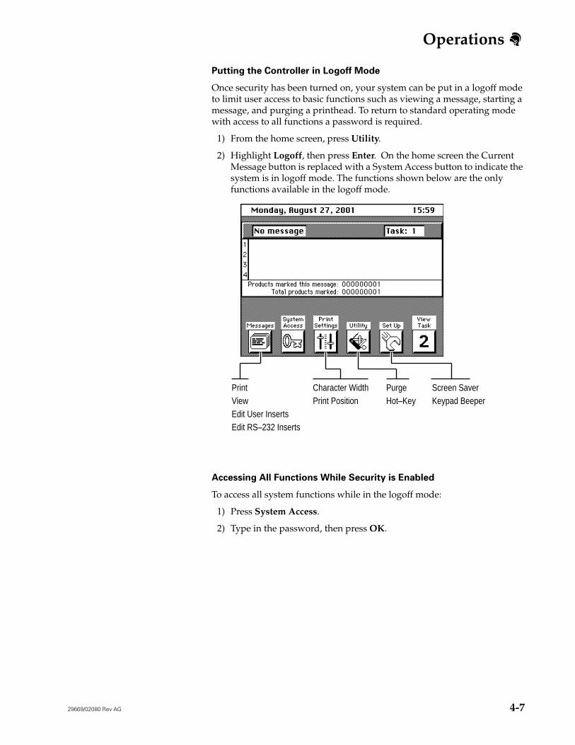
Putting the Controller in Logoff Mode
Once security has been turned on, your system can be put in a logoff mode to limit user access to basic functions such as viewing a message, starting a message, and purging a printhead. To return to standard operating mode with access to all functions a password is required.
1) From the home screen, press Utility.
2) Highlight Logoff, then press Enter. On the home screen the Current Message button is replaced with a System Access button to indicate the system is in logoff mode. The functions shown below are the only functions available in the logoff mode.
Accessing All Functions While Security is Enabled
To access all system functions while in the logoff mode:
1) Press System Access.
2) Type in the password, then press OK.
Screen SaverKeypad Beeper
PurgeHot–Key
Character WidthPrint Position
PrintViewEdit User InsertsEdit RS–232 Inserts
Operations
4-8 29669/02080 Rev AG
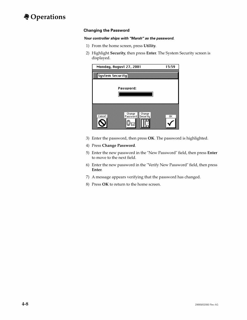
Changing the Password
Your controller ships with "Marsh" as the password.
1) From the home screen, press Utility.
2) Highlight Security, then press Enter. The System Security screen is displayed.
3) Enter the password, then press OK. The password is highlighted.
4) Press Change Password.
5) Enter the new password in the "New Password" field, then press Enter to move to the next field.
6) Enter the new password in the "Verify New Password" field, then press Enter.
7) A message appears verifying that the password has changed.
8) Press OK to return to the home screen.
Operations
29669/02080 Rev AG 4-9
Printhead Configuration Dual Tasking
Note: Custom Fonts and logos for HR Series printheads are not available on Task 2.
If you are dual tasking, you will need to configure the printheads for each task.
From the home screen, press View Task to switch between tasks before setting up your printheads.
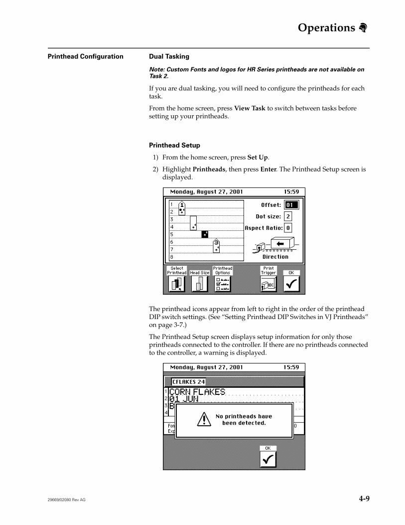
Printhead Setup
1) From the home screen, press Set Up.
2) Highlight Printheads, then press Enter. The Printhead Setup screen is displayed.
The printhead icons appear from left to right in the order of the printhead DIP switch settings. (See “Setting Printhead DIP Switches in VJ Printheads” on page 3-7.)
The Printhead Setup screen displays setup information for only those printheads connected to the controller. If there are no printheads connected to the controller, a warning is displayed.
Operations
4-10 29669/02080 Rev AG
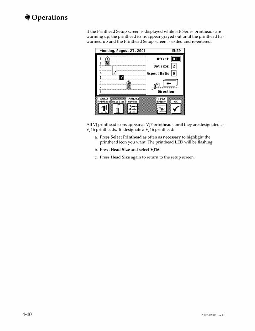
If the Printhead Setup screen is displayed while HR Series printheads are warming up, the printhead icons appear grayed out until the printhead has warmed up and the Printhead Setup screen is exited and re-entered.
All VJ printhead icons appear as VJ7 printheads until they are designated as VJ16 printheads. To designate a VJ16 printhead:
a. Press Select Printhead as often as necessary to highlight the printhead icon you want. The printhead LED will be flashing.
b. Press Head Size and select VJ16.
c. Press Head Size again to return to the setup screen.
Operations
29669/02080 Rev AG 4-11
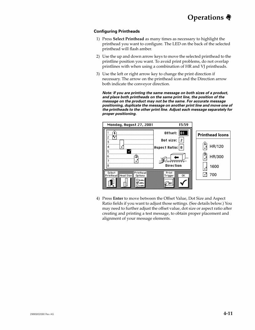
Configuring Printheads
1) Press Select Printhead as many times as necessary to highlight the printhead you want to configure. The LED on the back of the selected printhead will flash amber.
2) Use the up and down arrow keys to move the selected printhead to the printline position you want. To avoid print problems, do not overlap printlines with when using a combination of HR and VJ printheads.
3) Use the left or right arrow key to change the print direction if necessary. The arrow on the printhead icon and the Direction arrow both indicate the conveyor direction.
Note: If you are printing the same message on both sizes of a product, and place both printheads on the same print line, the position of the message on the product may not be the same. For accurate message positioning, duplicate the message on another print line and move one of the printheads to the other print line. Adjust each message separately for proper positioning.
4) Press Enter to move between the Offset Value, Dot Size and Aspect Ratio fields if you want to adjust those settings. (See details below.) You may need to further adjust the offset value, dot size or aspect ratio after creating and printing a test message, to obtain proper placement and alignment of your message elements.
HR/120
HR/300
1600
700
Printhead Icons
Operations
4-12 29669/02080 Rev AG
Offset Value
Determine the offset value for the printhead (see the table below), then enter that number in the offset field. The offset value will be applied to all messages that are printed with the printhead Be sure to adjust the offset value anytime you move a printhead.
Dot Size
Use the dot size setting to control the darkness of your print. The higher the number, the darker the print.
Aspect Ratio
If you are printing a message using both HR Series and VJ printheads, the width of the elements on each line may differ with the printhead type. Adjust the aspect ratio for each printhead individually if necessary, to achieve consistency in font width.
Zero (0) has been set as the default for VJ/HR Combo software.
Printhead Procedure
VJ Series Measure the distance from the photocell to the master printhead nozzle. Divide the distance by 0.8 if measured in inches, or 2 if measured in centimeters.
HR Series Measure the distance from the photocell to the printhead orifices in inches.
Printhead Available Dot Sizes
VJ Series 0 - 9
HR Series 1 - 4
Controller Software Aspect Ratio
VJ Printheads HR Series Printheads
VJ/HR Combo 1 to 9 (narrow to wide)0 = widest setting for compatibility of printhead types
0 to 9 (narrow to wide)
VJ Printheads Only 0 to 9 (wide to narrow) Not applicable.
HR Printheads Only Not applicable. 0 to 9 (narrow to wide)
Operations
29669/02080 Rev AG 4-13
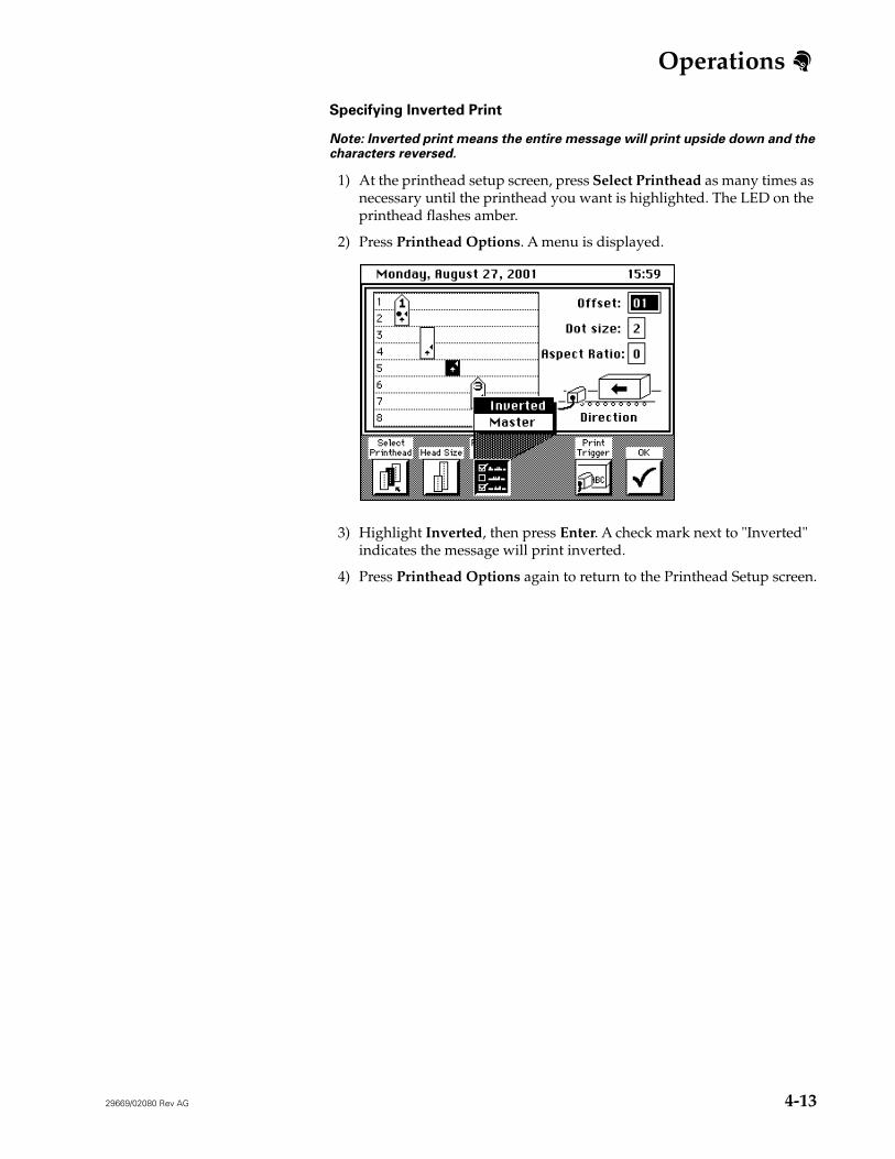
Specifying Inverted Print
Note: Inverted print means the entire message will print upside down and the characters reversed.
1) At the printhead setup screen, press Select Printhead as many times as necessary until the printhead you want is highlighted. The LED on the printhead flashes amber.
2) Press Printhead Options. A menu is displayed.
3) Highlight Inverted, then press Enter. A check mark next to "Inverted" indicates the message will print inverted.
4) Press Printhead Options again to return to the Printhead Setup screen.
Operations
4-14 29669/02080 Rev AG
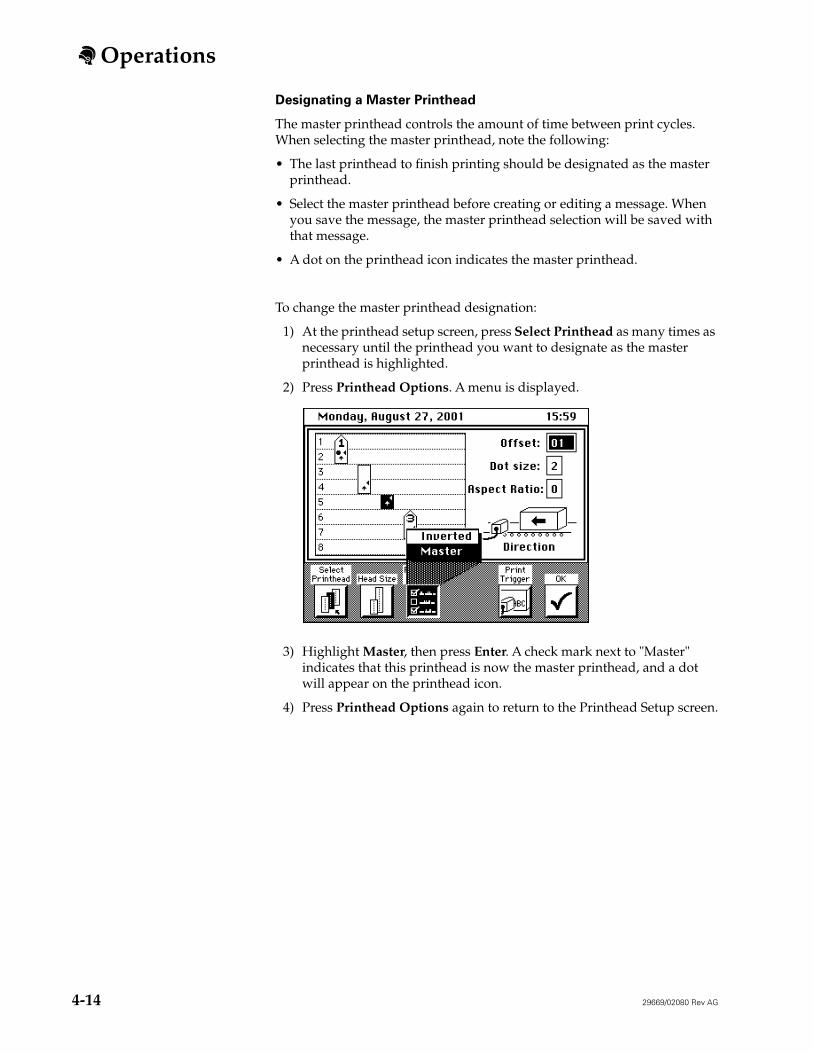
Designating a Master Printhead
The master printhead controls the amount of time between print cycles. When selecting the master printhead, note the following:
• The last printhead to finish printing should be designated as the master printhead.
• Select the master printhead before creating or editing a message. When you save the message, the master printhead selection will be saved with that message.
• A dot on the printhead icon indicates the master printhead.
To change the master printhead designation:
1) At the printhead setup screen, press Select Printhead as many times as necessary until the printhead you want to designate as the master printhead is highlighted.
2) Press Printhead Options. A menu is displayed.
3) Highlight Master, then press Enter. A check mark next to "Master" indicates that this printhead is now the master printhead, and a dot will appear on the printhead icon.
4) Press Printhead Options again to return to the Printhead Setup screen.
Operations
29669/02080 Rev AG 4-15
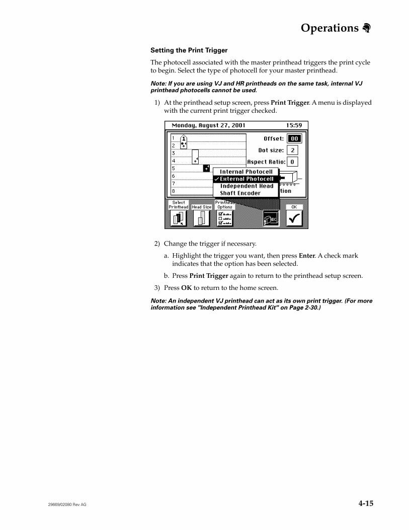
Setting the Print Trigger
The photocell associated with the master printhead triggers the print cycle to begin. Select the type of photocell for your master printhead.
Note: If you are using VJ and HR printheads on the same task, internal VJ printhead photocells cannot be used.
1) At the printhead setup screen, press Print Trigger. A menu is displayed with the current print trigger checked.
2) Change the trigger if necessary.
a. Highlight the trigger you want, then press Enter. A check mark indicates that the option has been selected.
b. Press Print Trigger again to return to the printhead setup screen.
3) Press OK to return to the home screen.
Note: An independent VJ printhead can act as its own print trigger. (For more information see "Independent Printhead Kit" on Page 2-30.)