NASA Technical Memorandum 86264 A ROUTE GENERATOR CONCEPT FOR AIRCRAFT ONBOARD FAULT MONITORING MICHAEL T. PALMER KATHY H. ABBOTT AUGUST 1984 National Aeronautics and Space Administration Langley Research Center Hampton,Virginia 23665
Transcript
NASA Technical Memorandum 86264
A ROUTE GENERATOR CONCEPT FOR AIRCRAFT
ONBOARD FAULT MONITORING
MICHAEL T. PALMER
KATHY H. ABBOTT
AUGUST 1984
National Aeronautics and Space Administration
Langley Research Center Hampton, Virginia 23665
SUMMARY
Because o f t h e i n c r e a s i n g l y complex environments i n which t h e f l i g h t crews of commercial a v i a t i o n a i r c r a f t must operate, a research e f f o r t i s c u r r e n t l y underway a t NASA Langley Research Center t o i n v e s t i gate t h e p o t e n t i a1 b e n e f i t s o f i n t e l l i g e n t cockp i t aids, and t o es tab l i sh gu ide l ines f o r t h e a p p l i c a t i o n o f a r t i f i c i a1 i n t e l 1 i gence techniques t o advanced f 1 i ght management concepts. The segment o f t h i s research area t h a t concentrates on automated f a u l t m o n i t o r i n g and diagnosis requi res t h a t a re ference frame e x i s t , against which t h e cur ren t s t a t e o f t h e a i r c r a f t may be compared t o determine t h e ex is tence of a f a u l t . Th is paper describes a computer program which generates t h e p o r t i o n o f t h a t reference frame that s p e c i f i e s t h e h o r i z o n t a l f l i g h t route.
INTRODUCTION
I n t h e commercial a v i a t i o n indust ry , safety and e f f i c i e n c y are o f utmost importance. F l i g h t crews must operate i n i n c r e a s i n g l y complex environments, and automation i n t h e form o f i n t e l l i g e n t cockp i t a ids may a s s i s t them i n i mprovi ng sa fe ty and e f f i c i e n c y Modern microprocessor and d i sp lay technol ogy have made it f e a s i b l e t o automate many f l i g h t deck funct ions, and t h e advent of expert systems technol ogy has proven t h a t a r t i f i c i a1 i n t e l 1 i gence ( A I ) has a great deal t o o f fe r t o enhance and aid t h e man i n t h e system. I n p a r t i c u l a r , automation o f f a u l t monitor ing and diagnosis i s des i rab le t o ensure sa fe and e f f i c i e n t operat ions, since response t o f a u l t s on board an a i r c r a f t i s o f t e n t ime c r i t i c a l . It i s be l ieved t h a t t h e use o f a r t i f i c i a l i n t e l l i g e n c e concepts can f a c i l i t a t e t h i s automation.
An e f f o r t i s c u r r e n t l y underway a t NASA Langley Research Center t o i n v e s t i g a t e t i re p o t e n t i a l b e n e f i t s o f i n t e l l i g e n t cockpi t a ids, and t o e s t a b i i s h guide1 i nes f o r t h e appl i c a t i on o f A I techniques t o advanced f l i ght management concepts. One a p p l i c a t i o n area w i t h i n t h i s research e f f o r t i s onboard f a u l t mon i to r ing and diagnosis. automated f a u l t mon i to r ing requi res that t h e ac tua l a i r c r a f t s t a t e be compared t o some des i red reference a i r c r a f t s ta te i n order t o de tec t t h e ex is tence of a f a u l t .
The segment o f t h i s area t h a t concentrates on
The a i r c r a f t s t a t e has been d iv ided i n t o p o r t i o n s t o f a c i l i t a t e t h e generat ion of t h e des i red reference a i r c r a f t s t a t e . A computer program has been developed t o generate t h e p o r t i o n o f t h i s reference s t a t e t h a t s p e c i f i e s a h o r i z o n t a l r o u t e m i n i m i z i ng ground d i stance between t h e o r i g i n and d e s t i n a t i on a i r p o r t s us ing t h e establ i shed a i rway system designated by t h e Federal
documents t h i s computer program and describes i t s use and capabi 1 i t i e s . . A v i a t i o n Admin is t ra t ion and i n use by Air T r a f f i c Contro l . Th is r e p o r t
BACKGROUND
The i n i t i a l concepts f o r t h e f a u l t moni tor ing and d iagnosis segment of t h e i n t e l 1 i gent f 1 i ght management research were devel oped a t t h e Uni v e r s i ty of
I 1 1 i noi s a t Urbana-Champai gn under a grant from NASA Langley Research Center ( r e f . 1). The major t h r u s t of t h e work was t o exp lo re the e x i s t i n g a r t i f i c i a l i n t e l 1 i gence techniques appl i cab le t o f a u l t mon i to r ing and d iagnosis w i t h i n t h e f l i g h t domain and, i f necessary, develop new techniques more s u i t e d t o t h i s app l i ca t ion . Out of t h i s research came t h e bas ic concepts f o r a m l t i - l e v e l a rch i tec tu re w i t h i n which t h e f a u l t mon i to r i ng segment would operate. The d e s c r i p t i o n and prec ise f u n c t i o n of each of t he l e v e l s w i t h i n t h i s a r c h i t e c t u r e have evolved as new ideas were incorporated.
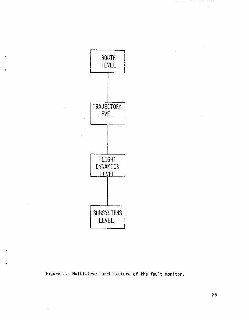
The bas ic a rch i tec tu re o f t he f a u l t mon i to r ing segment i s organized as a h ie ra rchy . The h ie rarchy cons is ts o f f o u r d i s t i n c t bu t in terconnected l e v e l s as shown i n Figure 1: t h e Route Level, t he T ra jec to ry Level, t h e F l i g h t Dynamics Level , and the Subsystems Level . I n general, each l e v e l i s subserv ient t o the one above it, supply ing t h e means o f achiev ing the goals which are passed t o i t from above. This ho lds t r u e except i n the case o f t h e Subsystems Level; t h e r e l a t i o n s h i p here could be more accura te ly descr ibed as a p recond i t i on -sa t i s fac t i on check. An exper t system i s inc luded w i t h i n t h i s framework t o handle a l l d iagnos t ic dut ies. The system a rch i tec tu re , t he mon i to r i ng funct ions, and the exper t system are w r i t t e n i n t h e LISP language d i a l e c t known as MACLISP, and t h e Route and T ra jec to ry Level Generators a re w r i t t e n i n FORTRAN 77. The f o l l o w i n g i s a general d e s c r i p t i o n o f each l e v e l w i t h i n t h e f a u l t mon i to r ing and diagnosis segment o f the i n t e l l i g e n t f l i g h t management research area.
The Route Level
The Route Level i s the h ighest l e v e l i n the a rch i tec tu re , passing along i t s goals and r e s t r i c t i o n s t o t h e T ra jec to ry Level These pr imary f l i g h t goals i n c l u d e t h e generated rou te and any time, weather, t r a f f i c , o r o ther A i r T r a f f i c Cont ro l (ATC) r e s t r i c t i o n s . The Route Level cons i s t s of two main sect ions, t he Route Generator and the Route Monitor. The Route Generator generates t h e shor test rou te f rom t h e c i t y o f depar ture t o the c i t y o f a r r i v a l , t a k i n g i n t o cons idera t ion cons t ra in t s such as weather cond i t i ons and ATC r e s t r i c t i o n s . f l i g h t t o determine i f t h e generated rou te i s being fol lowed.
The Route Moni tor cont inuously moni tors t h e progress o f t h e
The T ra jec to ry Level
This l e v e l a l so cons is ts o f two sect ions, t h e T ra jec to ry Generator and t h e T r a j e c t o r y Monitor. goals sent down from t h e Route Level Generator. Once these are received, t h e T r a j e c t o r y Generator produces an opt imal t r a j e c t o r y t h a t minimizes e i t h e r f u e l o r d i r e c t operat ing costs. F l i g h t Dynamics Level. The T ra jec to ry Moni tor moni tors the progress of t he f l i g h t f rom t h e v e r t i c a l - and time-based viewpoint , dec id ing whether o r no t t h e opt imal t r a j e c t o r y i s being proper ly fo l lowed.
The T ra jec to ry Generator u t i 1 i zes the pr imary fl i ght
The generated t r a j e c t o r y i s passed down t o t h e
2
The F l i g h t Dynamics Level
Th is l e v e l uses an i n t e r n a l model of the a i r c r a f t t o generate a l l necessary c o n t r o l i n p u t s such as wheel and column pos i t ions , t h r o t t l e p o s i t i o n s , and f l a p s e t t i n g s t h a t are requ i red t o achieve t h e des i red t r a j e c t o r y . sequence o f c o n t r o l i n p u t s i s then t r a n s f e r r e d down t o t h e Subsystems Level .
Th is
The Subsystems Level
The Subsystems Level checks t h e c o n t r o l i n p u t sequence and ampli tude t o assure t h a t t h e i n p u t s do not attempt t o extend t h e a i r c r a f t beyond i t s normal opera t iona l and performance l i m i t s . This l e v e l conta ins t h e knowledge about t h e a i r c r a f t subsystems, and checks t h a t each subsystem i s working proper ly .
When t h e checks a t t h e Subsystem Level have been completed, t h e F l i g h t Dynamics Level passes i t s sequence o f cont ro l inpu ts back up i n t o t h e T r a j e c t o r y Level, which then passes t h e generated optimum t r a j e c t o r y back up t o t h e Route Level. funct ions. Once t h e f l i g h t has been i n i t i a t e d , constant s u r v e i l l a n c e o f a l l c r i t i c a l parameters i s maintained, and i f any c o n d i t i o n i s observed t h a t has caused o r w i l l cause d e v i a t i o n from t h e planned route, t h e expert system i s ac t i va ted . The exper t system i t s e l f c u r r e n t l y uses a rule-based approach t o problem s o l v i n g as descr ibed i n r e f . 2, but t h i s w i l l l a t e r be expanded t o more c l o s e l y combine t h e func t ions o f e r r o r d e t e c t i o n and f a u l t d iagnosis i n t o a more u n i f i e d e f f o r t .
Here i t i s s to red f o r re fe renc ing by t h e r o u t e mon i to r ing
DESCRIPTION OF THE ROUTE GENERATOR
The Dn,,+- Cl l l r r r - ,+ r r 4 - . 4 r r 4 - r A ~ L - -..- L - - - -L .Cl.-L& -- & L a & 1 1 S B S G I\YUUG UCIIFI U~.UI 13 uea I Y I I C U I,U I U I I pi IUI t,u caul I i i ~ I I L 3u t,iiaL 5 I I c u r r e n t i n f o r m a t i o n on weather, t r a f f i c , and A i r T r a f f i c Contro l (ATC) i n s t r u c t i o n s can be used. are changed dur ing t h e f l i g h t so as t o render t h e p r e v i o u s l y generated r o u t e unacceptable, t h e Route Generator can be executed again us ing t h e next waypoint o f the path as t h e p o i n t o f departure, and t h e d e s t i n a t i o n a i r p o r t , whether d i f f e r e n t o r t h e same as o r i g i n a l l y planned, as t h e p o i n t o f a r r i Val . This i n f l i ght r e - r o u t i ng capabi 1 i t y i s t h e p r i n c i p a l advantage o f a program which a c t i v e l y generates t h e route r a t h e r than r e t r i e v i n g a r i g i d , preplanned course from a storage device. The Route Generator i t s e l f i s comprised o f two major sect ions, t h e Selector and t h e Compiler.
I f any o f these i n i t i a l c o n d i t i o n s o r i n s t r u c t i o n s
The Route Selector - The Route Se lec tor i s t h e sec t ion which chooses t h e s h o r t e s t a l lowable p a t h
System. w i t h i n t h i s program i n graph form, t h e nodes represent ing geographical re ference points , o r waypoints, and t h e arcs between these nodes denot ing t h e airway segments. Each arc must be assigned a we igh t ing f a c t o r . For t h e case
. from o r i g i n t o d e s t i n a t i o n us ing t h e establ ished High A l t i t u d e J e t Route For t h e purposes of analys is , the Je t Route System i s represented
3
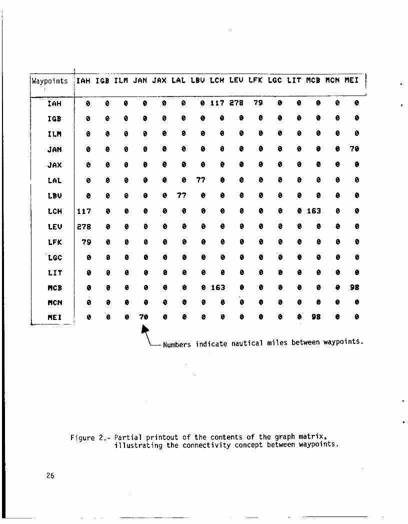
of l o c a t i n g the shor tes t path between any two nodes i n t h e graph, t h i s wei g h t i ng fac to r i s represented by t h e m i leage between waypoi n ts . con ta in ing t h e d is tance in fo rmat ion i s arranged so t h a t arcs are i d e n t i f i e d by t h e i r 1 o c a t i on w i t h i n the two-di mensi onal graph. The i ndex f o r each d i mensi on i s a p o i n t e r t o t h e name of t h e corresponding node (waypoint) i n t h e one- dimensional mat r ix con ta in ing the node i d e n t i f i e r s . Thus the graph, when p r i n t e d out, takes the form o f a mileage char t , w i t h on ly those mileages shown t h a t represent e x i s t i n g segments. A sample p o r t i o n o f t he graph i s shown i n f i g u r e 2. o f arcs from o r i g i n t o d e s t i n a t i o n nodes uses D i j k s t r a ' s a lgo r i t hm ( r e f . 3 ) . This a lgo r i t hm loca tes the path of l e a s t res is tance through an ar ray o f we igh t ing factors , and i s i d e a l l y s u i t e d f o r a p p l i c a t i o n t o t h i s p a r t i c u l a r c l ass o f problem.
The m a t r i x
The subrout ine which performs the actual s e l e c t i o n o f t ne sequence
The Route Compiler
The Route Compiler assembles the sequence o f t r a c k angles (no-wind t r u e headings) and the corresponding d is tances requi red t o f o l l o w the chosen path through t h e es tab l i shed system o f j e t airways, as w e l l as t h e magnetic v a r i a t i o n from t r u e no r th associated w i t h each waypoint i n the path. Th is sequence contains t h e rou te i n fo rma t ion needed by t h e T ra jec to ry Level f o r generat ion o f the optimum t r a j e c t o r y , s ince i t descr ibes the actual t r a c k o f t h e a i r c r a f t across t h e ground.
CONSTRUCTION OF DATA BASES
There are f o u r data bases access ib le by t h e Route Generator. base i s contained i n the ma t r i x c a l l e d NAME, which holds t h e names o f a l l t h e waypoints s tored i n a lphabe t i ca l order. The p o s i t i o n o f each waypoint name w i t h i n t h i s array i s very important, because the remaining data bases use t h i s pos i t i on as a poi n t e r f o r i d e n t i f y i ng segments between waypoi n t s w i t h i n t h e c o n n e c t i v i t y matr ix. conta ins a l l the i n fo rma t ion necessary t o permi t t h e Se lec tor t o choose t h e sho r tes t rou te through t h e airway system from o r i g i n t o des t i na t i on . Th is inc ludes t h e endpoints o f each segment, t he segment length, and t h e d i r e c t i o n s o f t r a v e l permiss ib le on each segment. The t h i r d data base conta ins the t r a c k i n fo rma t ion necessary f o r t h e Compiler t o assemble the e n t i r e sequence o f t r a c k angles and mileages f o r passage down t o the T ra jec to ry Level. The f o u r t h data base conta ins the magnetic v a r i a t i o n f rom t r u e no r th associated w i t h each waypoint.
The f i r s t da ta
The second data base, c a l l e d t h e pr imary data base,
Each e n t r y i n the pr imary data base l i s t s general i n fo rma t ion on one p a r t i c u l a r a i may segment. numbers, and has the f o l l o w i n g format:
The en t r y i s cons t ruc ted e n t i r e l y o f i n t e g e r
AAABBB CCC DDD E
4
where
.
AAA i s a p o i n t e r t o t h e l o c a t i o n o f the name o f t h e f i r s t endpoint i n t h e NAME array,
BBB i s a p o i n t e r t o t h e loca t ion of t h e name of t h e second endpoint i n t h e NAME array,
CCC i s t h e J e t Route designat ion number,
DDD i s t h e length, i n n a u t i c a l miles, o f t h a t e n t i r e segment, and
E i s a d i r e c t i o n c o n s t r a i n t f l a g i n d i c a t i n g t h e a l lowable d i r e c t i o n s o f t r a v e l on t h a t segment:
0 - open ( t r a v e l i n both d i r e c t i o n s permiss ib le )
1 - t r a v e l inbound t o f i r s t endpoint on ly
2 - t r a v e l inbound t o second endpoint on ly
For example, n o t i c e i n f i g u r e 3 t h a t F o r t Lauderdale DME i s named FLL. In t h i s implementation FLL i s loca ted i n the NAME array in p o s i t i o n 21. Orlando VORTAC i s named ORL, and i s l oca ted i n t h e NAME array i n p o s i t i o n 48. The segment connect ing these two waypoints i s designated 320, and has an o v e r a l l leng th o f 161 n a u t i c a l mi les. Therefore, t h i s segment i s s to red i n t h e pr imary data base as:
021048 020 161 0
r L a b - - z i z - - nInc t.1 a i I i i iy LCI u i s the d i i - e ~ t f ~ i i coiisti-sint f l a g , i i i d i c a t i i i g t ha t t h i s segment i s normal ly open t o t r a v e l i n both d i r e c t i o n s .
Each e n t r y i n t h e t h i r d data base a lso l i s t s in fo rmat ion on only one airway segment, and i s const ructed o f only in teger numbers, bu t here it has t h e f o l 1 owi ng format :
AAABBB FF GGGHHH I I IJJJ KKKLLL . . etc. where
AAA i s a p o i n t e r t o t h e l o c a t i o n o f the name o f t h e f i r s t endpoint i n t h e NAME array,
BBB i s a p o i n t e r t o t h e l o c a t i o n o f t h e name o f t h e second endpoint i n t h e NAME array,
FF i s t h e number o f d i f f e r e n t p o r t i o n s compris ing t h e airway segment,
GGG i s t h e t r a c k angle o f t h e f i r s t por t ion ,
5
HHH i s the distance, i n n a u t i c a l miles, t h a t t h e f i r s t t r a c k angle i s t o be fo l lowed
I11 i s the t r a c k angle o f the second por t ion , and
JJJ i s the distance, i n n a u t i c a l mi les, t h a t t h e second t r a c k angle i s t o be fo l lowed . . . etc.
A lso n o t i c e ir: f i g u r e 3 t h e path 320 takes between FL? and ORL. t r a c k s 339 degrees f o r 92 n a u t i c a l mi les, and then t r a c k s 334 degrees f o r 69 more n a u t i c a l miles, This in fo rmat ion f o r 320 i s represented i n the secondary data base as:
J2C f i r s t
021048 02 339092 334069
Since t h e exact l o c a t i o n o f a l l waypoints and t u r n i n g p o i n t s must be known i n order t o c a l c u l a t e t h e t r a c k angles, t h e in format ion f o r t h i s data base must be gathered f r o m o ther sources i n a d d i t i o n t o t h e Enroute High A l t i t u d e Charts which d i s p l a y the Je t Route System. The data base c o n t a i n i n g t h e magnetic v a r i a t i o n from t r u e nor th a t each waypoint i s s tored i n an array. Each element i n t h e array has associated w i t h it a VORTAC name and a character which i s " W " t o i n d i c a t e a wester ly magnetic v a r i a t i o n and "E" f o r an e a s t e r l y v a r i a t i o n .
The designated airways o f t h e J e t Route System are not t h e only a v a i l a b l e paths through the sky; however, they are t h e most d e s i r a b l e ones from t h e viewpoint o f ATC. c i t i e s not served by t h e System, and f o r f l i g h t s between c i t i e s where use o f t h e System would obv ious ly present a hindrance t o both t h e a i r l i n e f l i g h t crew and t h e ATC s t a f f . I n commercial a p p l i c a t i o n s o f t h i s f l i g h t p lann ing program, therefore, t h e data bases w i l l need t o be t a i l o r e d t o t h e e x i s t i n g s t r u c t u r e o f a l lowable r o u t i n g f o r each i n d i v i d u a l a i r l i n e .
Special clearances are r o u t i n e l y granted f o r f l i g h t s t o
RESULTS AND DISCUSSION
Several sample runs were made t o demonstrate t h e c a p a b i l i t y o f t h e program t o produce t h e shor test rou te between waypoints. generator program are i l l u s t r a t e d , i n c l u d i n g t h e c a p a b i l i t y o f revers ing d i r e c t i on and of speci f y i ng t h a t c e r t a i n f l i ght segments are undesi rab le.
Various features o f t h e rou te
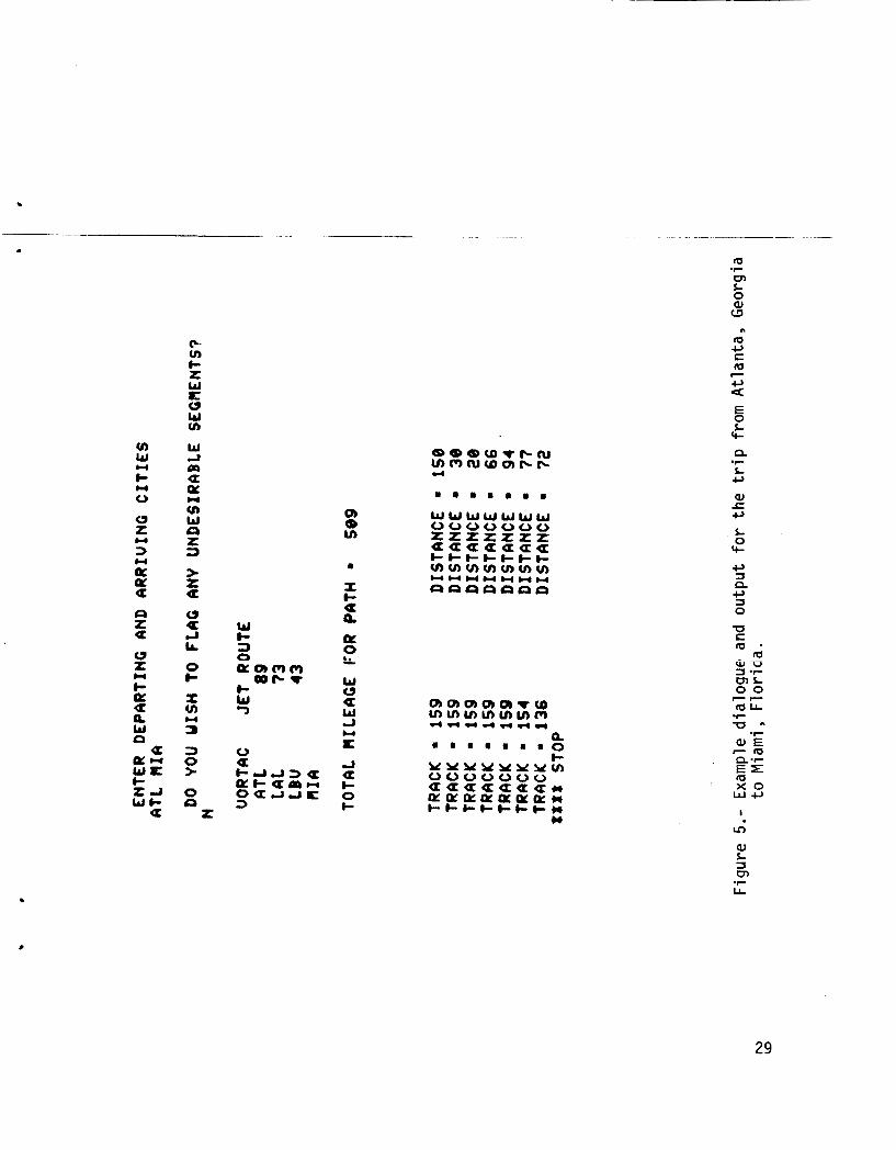
The f i r s t example i l l u s t r a t e s a case which was run f o r t h e t r i p between Miami, F l o r i d a and At lanta, Georgia. user w i t h t h e route generator program and t h e output o f t h e program. The user speci f i e s t h e departure and a r r i Val p o i n t s and any undesi r a b l e segments. program produces a l i s t o f t h e airways segments and corresponding mileages t h a t make up the generated route. (MIA), LaBel le VORTAC (LBV), Lakeland VORTAC (LAL), and A t l a n t a VORTAC (ATL). The Je t Route segments l i s t e d inc lude J43 between M I A and LBV, 573 between LBV and LAL, and 589 between LAL and ATL.
F igure 4 shows t h e i n t e r a c t i v e d ia logue o f t h e
The
The waypoints l i s t e d i n c l u d e Miami VORTAC
6
The second example i s t h e reversa l of the f i r s t example t r i p . The departure p o i n t i s A t l a n t a and t h e d e s t i n a t i o n i s Miami. t h i s example, which shows the revers ing f u n c t i o n o f t h e subrout ine GNRATR. GNRATR adds 180 degrees t o t h e t r a c k angles and reverse t h e i r order whenever t r a v e l occurs i n t h e d i r e c t i o n opposi te from t h a t i n which t h e t r a c k and mileage i n f o r m a t i o n i s stored.
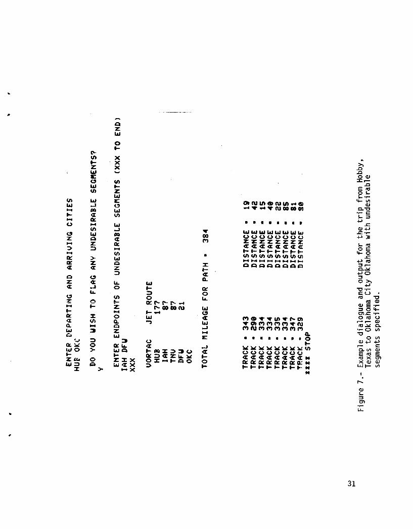
Two sample runs t h a t i l l u s t r a t e t h e a b i l i t y o f the program t o p lan around rou te segments t h a t have been f 1 agged as unacceptable are i 11 u s t r a t e d i n f i g u r e s 6 and 7. These runs demonstrate t h e f a c t t h a t t h e program does always choose t h e shor tes t path between waypoints. Both cases were run f o r t h e t r i p between Hobby, Texas and Oklahoma City, Oklahoma. The waypoints l i s t e d i n c l u d e Hobby (HUB), Humble (IAH), Navasota (TNV), Da l las - Ft . Worth (DFW), and Oklahoma City (OKC). The J e t Route segments l i s t e d i n c l u d e 3177 between HUB and IAH, 587 between I A H and TNV, 533 between I A H and DFW, 387 between TNV and DFW, and 321 between DFW and OKC.
F igure 5 shows t h e r e s u l t s o f
CONCLUDING REMARKS
The computer program f o r generat ing a hor izon ta l rou te t h a t minimizes ground d is tance has been i d e n t i f i e d as p a r t o f t h e f a u l t mon i to r ing f u n c t i o n o f an onboard f a u i t mon i to r ing and diagnosis system. Using a small subset o f t h e geographical re ference p o i n t s i n t h e High A l t i t u d e Je t Route System, t h e program has been demonstrated t o generate t h e shor tes t rou te between s p e c i f i e d source and d e s t i n a t i o n a i rpor ts . The capabi 1 i ty o f t h e r o u t e generator program t o r o u t e around path segments designated as undesi rab le was a l s o demonstrated.
7
APPEND I X
Descr ipt ion, Recommendations, and Source L i s t i n g o f Program ROUTEGEN and Subroutines LOADER, NOGOOD, SLECTR, GNRATR, and MAGVAR
The computer program descr ibed i n t h i s paper was w r i t t e n i n FORTRAN 77 on a Prime 750 mini-computer, running under t h e Primos* opera t ing system. A Tek t ron ix 4014-1 was iised f o r t h e remote te rmina l . The pr imary data base i s s tored on d isk as t h e f i l e named SEGDAT, and t h e secondary data base i s s to red as t h e f i l e named TRACKDAT.
.
Program ROUTEGEN
Descr i p t i on
This i s the d r i v e r program fo r t h e subrout ines which perform t h e actual func t ions o f se lec t ion and generat ion of t h e route. The o r i g i n and d e s t i n a t i o n are read i n from t h i s l e v e l , and t h e se lected rou te i s output from t h i s l e v e l .
Recommendations
1. The program c u r r e n t l y communicates i n t e r a c t i v e l y w i t h t h e user v i a a CRT terminal . I f desired, p o i n t s o f departure and a r r i v a l could be pre-programmed o r read i n from another source, and t h e output could be p r i n t e d out on a NAV d i s p l a y o r s tored f o r f u t u r e reference by t h e p i l o t .
2. The c a l l t o t h e subrout ine LOADER could be e l i m i n a t e d by s t o r i n g a l l o f t h e p r i m a r y data base in fo rmat ion i n t h e appropr ia te ar rays through t h e use of DATA statements. The execut ion t ime would d e f i n i t e l y decrease, bu t t h e program s i z e would increase. Depending on t h e o v e r a l l s i z e of t h e graph network, t h i s may or may not be a des i rab le a l t e r n a t i v e .
Source L i s t i na
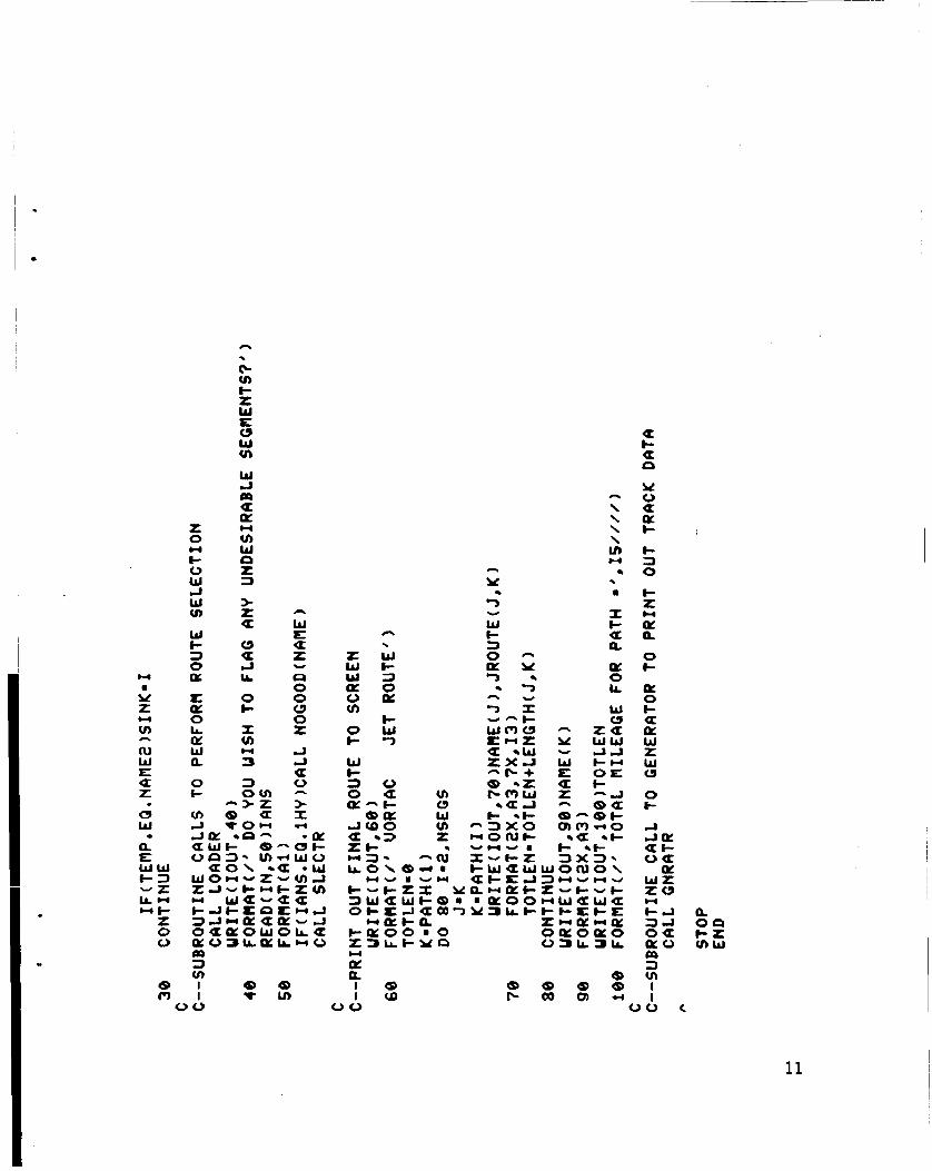
The l i s t i n g o f program ROUTEGEN i s as fo l lows:
a
c z W E
2
Y Z
tn
W 0 K 3 0 m z W J I-
4
m
4
E z W tn L
8 N
X c U a \ N 2 J m \
z 0 E E 0 0
4 n
Y
z 0
c a (I: 3cl z I-a
= a a 0 LLLL
1 1 1 1 l 1
c 3 0
z \ (3 Y cl PD \
2 0 E E O 0
U 4
w
4 4 4 4 4 4 4 4 4 4 4 4 4 \
u o m 3 m x Y ~ > w e v ) o x
. I
CI
m * o! I 0
v) O U
a
Y
t U 0
4 4 4 4 4 4 4 4 4 4 4 4 4 4
W I I I I-K
O W
E W W e w
L Z o w
u+cu a v U:EE a t z a a IT
000000
W z z a
a 0) t CD U P L * . . . . . . . . * . . .
O
c) 2 a
(3 w z I - t >
w I W 0 K 3 0 v)
W w
10
M a Y z v)
tu w E z Q w
E W W 63 WZ kn Wf- z
0 0
c(
CI
a *
n
8 m
.. t- z W E 0 W VI
W A PD a e z H
0 v) n W I- CI 0 z W 1 A W > v) z W t c3 3 a
CJ
L 0 Q! &- 0 LL. I a v) w w 0 3 0
a
E IL
h
W L= a z a 0 0 0 0 I J J
Y
a
00
z w W
0 v)
0 c- W I- 3 0
a
n
W e- 3 0
t w 7
. a
w a s-2 % w w w a * w - JJ 2 Z X J w c w w
w m o - za [zt
c- 1 0
t- z n U a
1 8 I C D
00 00 c
11
APPENDIX
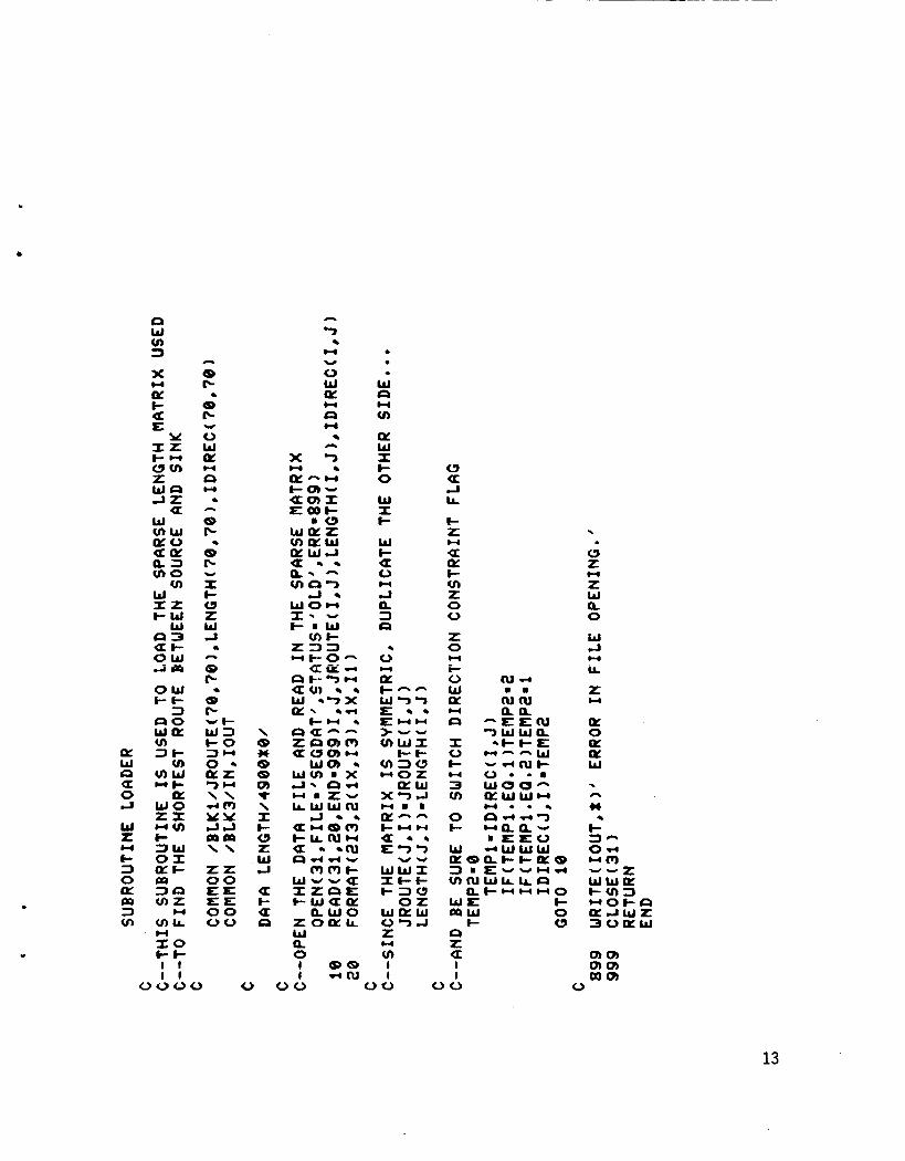
Subrout ine LOADER
Descr i p t i on
This subrout ine s tores the i n fo rma t ion from the pr imary data base i n t h e appropr ia te arrays. To minimize s torage requirments, t h i s i n fo rma t ion i s g iven i n t h e primary data base f o r t rave! i n one d i r e c t i o n only. That i s , a l l t he segments are s to red heading genera l l y south-to-north. As t h e i n fo rma t ion i s being read i n t o the d i f f e r e n t matr ices, it i s s to red i n both the south-to- no r th and t h e north-to-south pos i t i ons .
Recommendations
1. The LENGTH array needs t o be zeroed be fore t h e mileage in fo rma t ion can be read i n , and i t has been done here us ing a DATA statement. Th is has the e f f e c t o f inc reas ing the storage requirements d ramat ica l l y . A s lower bu t more space e f f i c i e n t method would be t o EQUIVALENCE t h e LENGTH ar ray t o a one-dimensional array, and then zero i t us ing a s i n g l e DO loop. I f a machine-dependent f u n c t i o n i s ava i l ab le f o r t h i s purpose it should be used i n any implementat ion which s t i l l makes use o f t h e LOADER subrout ine.
Source L i s t i n g
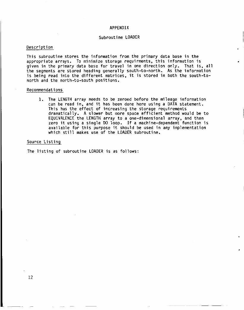
The l i s t i n g o f subrout ine LOADER i s as fo l l ows :
a! W c3 a 0 ct
W I w t- 3 0 CL: Po 3 v)
n
8 IC
8 IC
0 W a!
c,
4
v
H
U 4
A
8 IC
8 IC
I t a Z W A
a [c
8 IC -6 w 3 I-0 3- 0 - U L 7 - \ \ 40 Y Y 4 J moo \ \
Z L 0 0 EE E=E 0 0 00
4
U
4 n
4
\ 8 * 8 8 Q) t \ I e 0 Z w J
a t- a n
I 8 8 I d n l
W U SJ
LL
e z U a! I- v) z 0 0
I 0
i 0 W a CI
I 0 e 3 v)
0 e
W
W
w
W
L I a
13
APPEND I X
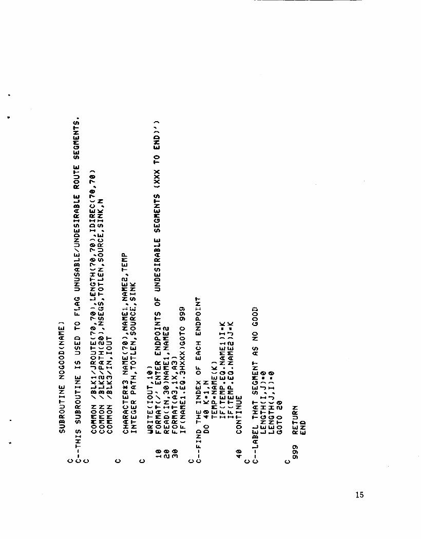
Subrout ine NOGOOD
Desc r ip t i on
This subrout ine al lows c e r t a i n airway segments t o be se lec ted and l a b e l l e d as unacceptable, f o r reasons of t r a f f i c , weather, o r ATC cons t ra in t s . The subrout ine queries the user fo r t he endpoints of each bad segment, and then i n s e r t s a zero f o r t he mi leage of t h a t segment i n the LENGTH mat r i x . Th is e f f e c t i v e l y removes the segment from cons idera t ion w i t h i n t h e SLECTR subrout ine.
Recommendations
1. A l l t he i n fo rma t ion needed fo r l a b e l l i n g unacceptable segments could, i f desired, be read i n from a source o ther than i n t e r a c t i v e communication w i t h a user. A r e a l i s t i c implementat ion o f t h i s program might have t h e t r a f f i c , weather, and ATC c o n s t r a i n t s s to red i n a dynamic data base, poss ib ly being r e g u l a r l y updated by a data base moni tor /modi f ier program. The Route Level Moni tor would then need t o p e r i o d i c a l l y check the s ta tus of a l l segments i n t h e planned rou te t o determine i f m o d i f i c a t i o n o f t h e chosen f l i g h t p lan i s necessary.
Source L i s t i n g
The l i s t i n g o f subrout ine NOGOOD i s as fo l lows:
14
W E a Z
0 0 0 0 Z
w z I- 3 0 a 3 v)
W
n
w
m
. v) I- z w E 0 W v)
W I- 3 0
W J m
a
a a CI cn W Q z 3 \ w cr p9 a v) 3 2 3
u I 9 LL
0 f-
cs w u) 3
u) I 4
w z I- 3 0 LLI 3 v)
v)
I I- t
w
m
U
I
n
n %
rs z w 0 f-
X X X
cn c z w IC 0 W u)
w a LD p:
v) W Q L 3 lL 0
Y
a w
A V.
cn m m
f- z 0
c) z w 1 0 U w IL 0
L . l--.
n
y e * - 0 0 w w w
X Z E
6 z 0 0
CICS 0 % n LL I e I
arxcU z arxcU z It-c & f-uuo 3 zzc ccI J W W O W L
a d Q, a I I
15
APPEND I X
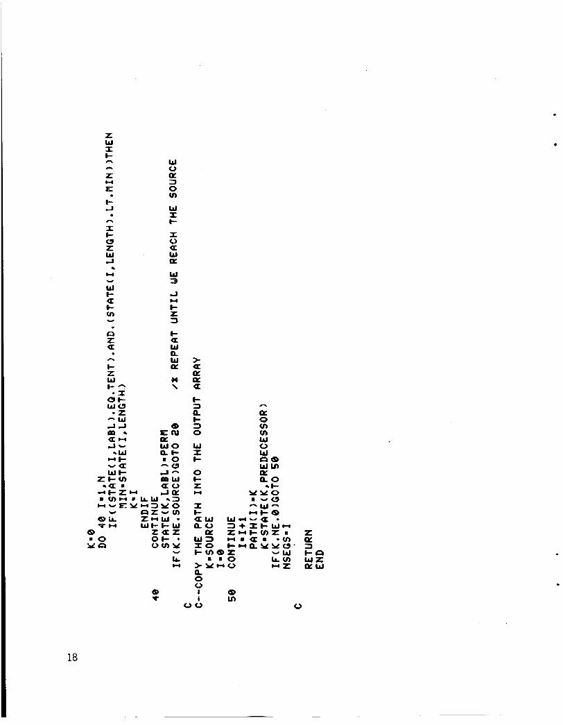
Subrout ine SLECTR
Desc r ip t i on
This subrout ine uses D i j k s t r a ' s a lgo r i t hm ( r e f . 3) t o f i n d t h e path o f l e a s t res i s tance (smal lest t o t a l mi leage) through t h e LENGTH array. Minor modi f i c a t i o n was necessary t o incorpora te t h e d i r e c t i on const r a i n t f l ag capabi 1 i ty , bu t t he a1 g o r i thm i t s e l f remains bas i ca l l y una1 tered.
Source L i s t i n g
The l i s t i n g o f subrout ine SLECTR i s as fo l l ows :
16
.
a I- o w bl v)
W z c 3 0 p:
3 v)
W
m
* X
p: c E:
I c a z W J
W
c I 0 3 0 p: I e I t- a Q
e * v)>
CQ: (ILQ:
X v)- I
W t X U
v) Y W O X HI- a
Z w w z Ht cH 3 O W QCW
30 at-
v) v, W Q S Z
I I
n
a
r
w a
oa
ea %
m w
ha i i
0 0 0 0 0
4
Y L u)
W O aL 3 0 u)
z W cl c O I-
I I- a
a
0
(P F
u c U
w
4
4
4
a
4 A
4
U
w aa 0 W Q I - + z a w e
* *
X
c E W c
U
a
W N
II c e 2
1 I
W
H
w
c.(
00
8 H
8
0
4
n
W c c v)
a W W c c c c v)v)
a a
Y z v)
W i-
I- v)
w
Y
a
Y z v)
Y
cc
8
cc. Y
E 0 Q: LL
I c a Q
a W c c w
. n 2 a
v) n . .
1 8 I t l a
0 0
.
J W
a J
e v) W cl a c E v)
W I e I I-
3
W 0 0 z n W cl 4 W m U J
> bl W > 2c c z ClL Z L W- I-. L
W b l I E I-
c3 2
LL 1
m
H
Ut4
a n
U
(0 m 1 0 0
z W I c
L E
I- 4 n
I I- W Z W L,
A
n
w .
4
U v
W t- a I- u) Y
ta L Q
I- Z W f - n * I oc
W O - 2
- W L,a
2- * w
wl-
Wl- Lev)
. n
m a a w
-a
W 0
3 0 v)
W I t
I 0 U W K
W 3
J
I- 2 3 I- a W Q W
* \
a
w
a
8 E N
w o Q C m O -a
a
a- m w
w I I- O c
0 W a 8 W v , K n o 4c
I In 0 0
18
APPEND I X
Subroutine GNRATR
. Descr i D t i on
.I This subrout ine compiles t h e t r a c k angle and mileage sequence from t h e t h i r d data base. The cur ren t technique used f o r t h i s purpose employs a simple, b u t slow, process o f searching t h e e n t i r e data base fo r each l i s t o f segment in fo rmat ion . As each segment l i s t i s located, i t i s p r i n t e d out t o t h e CRT screen according t o t h e d i r e c t i o n of t r a v e l . I f t r a v e l occurs i n t h e d i r e c t i o n opposi te t h a t i n which t h e segment i n f o r m a t i o n i s stored, 180 degrees are added t o t h e t r a c k angles, which are output i n reverse order w i t h t h e i r m i 1 eage.
Recommendations
1. A much f a s t e r search method would inc lude s t o r i n g t h e airway segment data i n t h e same sequence w i t h i n both data bases. An ar ray of p o i n t e r s t o t h e l o c a t i o n o f each chosen segment could be f i l l e d a t t h e same t ime as t h e ar ray of p o i n t e r s t o t h e waypoint names, known as t h e PATH array. The t r a c k and mileage i n f o r m a t i o n could be compiled much f a s t e r w i t h the few number o f d i s k f i i e operat ions requi red. Once assembled, the subrout ine GNRATR c u r r e n t l y merely p r i n t s t h e t r a c k and mileage in fo rmat ion t o t h e CRT te rmina l screen and t o a f i l e f o r l a t e r use by t h e T r a j e c t o r y Level. When combined w i t h o ther computer programs t h a t perform t h e func t ions of t h e o ther l e v e l s i n t h e f a u l t monitor ing and d iagnosis segment's bas ic a r c h i t e c t u r e , t h i s in fo rmat icn w i l l be used by t h e T r a j e c t o r y Level.
Source L i s t i n g
The l i s t i n g o f subrout ine GNRATR i s as fo l lows:
L
19
zna.
w a I - x a a
cnnx
W v ) w s
I -OR 0
w w a:Z+ ma:
W a-Z I-v)O aacl aza
z Y z v)
W 0 e 3 0 cn z W a I- 0 I-
v) 0 W u, L
4
c(
4
4
4 n
d Ln
t v, n
v
n
0 a E W f-
ru E: W e
.)
a
4 d a E W e e tn n Y 0 ac a: t-
Y z cn W 0 ar: 3 0 v)
z W cl f- 0 c I c a. 0: W W W c z
4
w
4
4
w
4
4
a
w
0 LL z
Y 0 U 0: e z w w X I I-I-
k- =lX o w
E) I-z Z ?
a0 & W
4 J
U
A
n *
X i 5 d w z 2-9
W 0 8 X W t e *
Y O v)-cI
LL v)H
I c
t-8-
n
1 1 1 1
LL I I
W
Y
w I-
3
w a
t- U L Q C I
z W I I-
20
L
* (0 0
I <u
E W I-
cu R S W &--
a
a
rc
W v, a m a a I- c)
W I t-
z W z .I
t- X W z W I f-
c) U W m
8 Zd W I O c-c- 0 *a
I- 0 z Lc w
I
w
?-.?
u m 3 m za, I-0 I t 0 0 0 0
w
W 0 0
W a Y LL
2 1
APPENDIX
Subroutine MAGVAR
D e s c r i p t i o n
This subrout ine r e t r i e v e s t h e magnetic v a r i a t i o n o f each p o i n t along t h e path from t r u e nor th . The data base i s searched us ing a s imple sequent ia l search u n t i l t h e desired waypoint names are found. The magnetic v a r i a t i o n f o r each waypoint i n t h e chosen path i s s to red i n an ar ray c a l l e d VAR - MAG.
Source L i s t i n g
The l i s t i n g o f MAGVAR i s as fo l lows:
22
I I
I I I I Y I I m I m I I n I I I I I I m I I m I -
a
iE W m E 3 z
I Q & 0
a 4
c3 2 a w e 'I i- a
I- - 4
II, m 0 c-
8 N
8 0
.)
v
n a u 1y
8 cu
r(
I
v 8 m 0 &a
a
a
I a CJ
U
LL +-I
I- o w Ly
CI w
z Q! 3 t- w cy:
n
+ + + w CJ
LL
a F
cs z 0
c Q
CLL U 3
z
.
U
a
U
U
H
a z 1 0 LL
LL 0 W
+ + . + .)
X
k-
E U 0 L1-
4 Y
a P L w
23
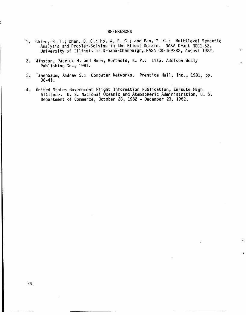
REFERENCES
1. Chien, R. T.; Chen, D. C.; Ho, W . P. C.; and Pan, Y . C.: M u l t i l e v e l Semantic Analysis and Problem-Solving i n the F l i g h t Domain. Un ive rs i t y of I 1 1 i n o i s a t Urbana-Champaign, NASA CR-169282, August 1982.
2. Winston, Pat r i ck H. and Horn, Berthold, K. P.: Pub1 i sh i ng Co. , 1981.
NASA Grant NCC1-52,
. .
L isp. Addison-Wesly
3. Tanenbaum, Andrew S.: Computer Networks. Pren t ice Ha l l , Inc., 1981, pp. 36-41.
4. Uni ted States Government F l i g h t In fo rmat ion Pub l ica t ion , Enroute High A l t i t u d e . U. S. Nat ional Oceanic and Atmospheric Admin is t ra t ion , U. S. Department o f Commerce, October 28, 1982 - December 23, 1982.
,
ROUTE LEVEL
.I
FLIGHT D Y l A M I CS
Figure 1.- Multi-level architecture of t he fault monitor.
25
JAX LAL LBU LCH LEU LFK LCC L I T flCB MCN ME1 . e e e e 1 1 7 2 7 8 7 9 e e e e e *
26 L-
I LPl
JhN
JAX
LAL
LBU
LCH
LEU
LFK
LCC
L I T
HCB
PlCN
UEI _ _ __
Figure 2.- Partial printout o f the contents o f the graph matrix, illustrating the connectivity concept between waypoints.
I e e e e e e e e e e e e e e e e e e e e e e e e e e e e e m e e e e e e e e e e e e e e e e e e e e e 7 7 e e e e e e e e e e e e 0 7 7 e e e e e e e e e
117 e e e e e e e e e e 8 1 6 3 8 e 278 e e e e e e e e e e e e e e
7 9 e e e e e e e e e e e e e e e e e e e e e e e e e e e e e e e e e e e e e e e e e e e e e e e e e e e 1 6 3 e e e e e e 9 8
e e e e e e e e e e e e e e e , e e e y e e e e e e e e e 9 8 e e
F i g u r e 3 . - S o u t h F l o r i d a p o r t i o n o f Enroute High A l t i t u d e .
27
CL v) I- z W E 0 w v)
W J
oc v, w CI 2 3
m a U
v) w I-
0
CI - 0) 8 u) L
8 Y-
8
X c a a
c, 3 a a a a
> z U U
i 0 a
a 2 0
J LL
0 e I v)
3
a
w
Qc 0 L 0 z
w c-
0 w CI
a a
W u w J
= J
t 0 t-
a
CI
a - *? (21 Uc,
S
3 0 >
J a t w u t
W W L
z a 0 CI ' 2
28
.-
cn L 0 aJ t3
tu c, E
0- tn L z w L: 0 w v)
E 0 L ce
u) w w e) W 09 t a w p: 0 CI
v) 0 W z CI w z 3 3
p: > Q: f a U
w
P
L c, -I-
0) Q) u)
w I W 0 z c v)
a
w 0 z c v)
a
w 0 z + m a
W 0 z U c
0 z a L 0 ce
v) c, 3 Q L) 5 0
W c a * a
0
w J
a
CI IC
0
I
In aJ L 3 m
29
. ,
in CrJ x aJ I- .I
v) w + 0
0 z 3
a:
Q 2 U
U z e- & U
w cs 0
QCY w o t
W 3 X
w
w
c.(
U
a a
w
a
z m
0 v) I- z W I: u
0 CI z
W 7
d 00 0
a a QL 0 Ir,
W u a ~
W J
t W
a a c 0 c
Y Y Y Y I L Y L ) 0 0 0 0 0 0
h n n 0 =I=
Q.
L Q
.r
L 0 rc
-7
QY
x o W Q
Z0
.
30
0 e CL
v) w e 0
w
w
w K K a ca z U 0 t U e cc: U a
v) X t- X z X W W
I= u v) w e v) z w w t a 0 m W a v)
> z a
3 0 z 0 0
>.
W J a a
0 U
t 00 PI
a
I c U a cy 0 LL
W W
u J
L:
4 U c 0 c
a
w
I
h
aJ L 1 m
31
1. Report No. NASA TM-86264
August 1984 6. Performing Organization Coda A Route Generator Concept f o r A i r c r a f t
Onboard F a u l t Mon i to r ing 505-35-13-04
2. Government Accession No. 3. Recipient's Catalog No.
7. Author(s1 Michael T. Palmer
4. Title and Subtitle
8. Performing Organization Report No. I
5. Report Oatr
10. Work Unit No, Kathy H. Abbott 9. Performing Organization Name and Address
L 11. Contract or Grant No. NASA Langley Research Center
Hampton, VA 23665
12. Sponsoring Agency Name and Address
Nat ional Aeronautics and Space Admin is t ra t ion Washi ngton, DC 20546
C 13. Type of Report and Period Covered
Technical Memorandum 14. Sponsoring Agency Code
19. Security Classif. (of this report] 20. Sccurity Classif. (of this page)
U n c l a s s i f i e d Unc lass i f i ed
16. Abstract
Because o f t h e i nc reas ing l y complex environments i n which t h e f l i g h t crews o f commercial a v i a t i o n a i r c r a f t must operate, a research e f f o r t i s c u r r e n t l y underway a t NASA Langley Research Center t o i n v e s t i g a t e t h e p o t e n t i a l b e n e f i t s o f i n t e l l i g e n t cockp i t a ids, and t o e s t a b l i s h gu ide l i nes f o r t h e a p p l i c a t i o n o f a r t i f i c i a1 i n t e l 1 i gence techniques t o advanced f l i ght management concepts. segment o f t h i s research area t h a t concentrates on automated f a u l t mon i to r ing and d iagnosis requ i res t h a t a re ference frame e x i s t , against which t h e cu r ren t s t a t e o f t h e a i r c r a f t may be compared t o determine the ex is tence o f a f a u l t . descr ibes a computer program which generates the p o s i t i o n o f t h a t re ference frame t h a t s p e c i f i e s t h e ho r i zon ta l f l i g h t route.
The
Th is paper
21. NO. of Pagcr 22. Rice
32 A0 3
17. Key Words (Suggested by Author(r) 1 f 1 i ght management a r t i f i c i a1 i n t e l 1 i gence r o u t e p l anni ng
18. Distribution Statement
U n c l a s s i f i e d - Un l im i ted
Subject Category 04
N-305 For sale by the National Technical Information Service, Springfield, Vlrglnla 22161