TECHNICAL MEMORANDUM (NASA) 13 FLIGHT EVALUATION: OHIO UNIVERSITY OMEGA RECEIVER BASE A description is given of the data-collection flight, round-trip from Athens, Ohio to Langley Field, Virginia, during which Omega data was collected on machine-readable media for use in aOr the Tri-University Program in Air Transportation. tZn by Kent A. Chamberlin Robert W. Lilley Richard J. Salter !1- a Avionics Engineering Center n 4 Department of Electrical Engineering Ohio University r Athens, Ohio 45701 November, 1974 4 4s. Supported by CU, National Aeronautics and Space Administration ' Langley Research Center Langley Field, Virginia u 3 , _j Grant NGR 36-009-017 I- CD Ohio Uiversty 0) Athen, Oho 4501co a567bg7( n https://ntrs.nasa.gov/search.jsp?R=19750005766 2018-07-03T13:41:17+00:00Z
Transcript
TECHNICAL MEMORANDUM (NASA) 13
FLIGHT EVALUATION: OHIO UNIVERSITY OMEGA RECEIVER BASE
A description is given of the data-collectionflight, round-trip from Athens, Ohio to LangleyField, Virginia, during which Omega data wascollected on machine-readable media for use in
aOrthe Tri-University Program in Air Transportation.
tZn
by
Kent A. ChamberlinRobert W. LilleyRichard J. Salter !1- a
Avionics Engineering Center n 4Department of Electrical Engineering
Ohio University rAthens, Ohio 45701
November, 1974 4 4s.
Supported by
CU,National Aeronautics and Space Administration '
Langley Research CenterLangley Field, Virginia u 3 , _j
II TEST FLIGHT - ROUND TRIP ATHENS, OHIO TO LANGLEY FIELD,VIRGINIA 2
A. General 2
B. Aircraft Instrumentation 2
C. Flight Path Documentation 2
D. Omega Navigation During the Flight 3
E. Omega Data Description 5
III CONCLUSIONS AND RECOMMENDATIONS 7
IV ACKNOWLEDGEMENTS 9
V REFERENCES 10
VI APPENDICES 11
A. Flight:Path and Omega LOP's 12
B. FORTRAN Program FDSUM - Omega Flight Data Summary 16
C. Selected Positional Error Data 21
I INTRODUCTION
The purpose of this Technical Memorandum is to document a flight evaluationof the Ohio University Omega Receiver Base, developed under the NASA Tri-UniversityProgram in Air Transportation, and to provide a vehicle for the transfer of flight-test datato NASA and to other participants in the Tri-University program.
Chart recordings of flight data are given, along with chronological listingsof significant events which occurred during the flight. Digital data has been prepared indata-processing card form for distribution. Data include phase measurements from all eightOmega time-slots for the duration of the flight, plus event marks which serve to correlatethe phase data with flight-path documentation.
It is anticipated that the data-collection and preparation techniques developedfor this flight will be maintained and improved for future flight evaluation. We welcomecomments on data form and content so that improvements in data usability may be made in thefuture.
PRX1 EDjNG PAGVE j3LANK IVA FLMEJ
11 TEST FLIGHT-ROUND TRIP ATHENS, OHIO TO LANGLEY FIELD,. VIRGINIA
A. General. A flight test of the Ohio University Omega Receiver Base devel-oped under the NASA Tri-University Program in Air Transportation Systems was planned forOctober 17-18, 1974 to coincide with a meeting of the Tri-University participants atLangley Field, Virginia. In this manner we were able to use DC-3 aircraft flight time bothfor transportation of program personnel to the meeting and for flight data-collection activi-ties. Details of receiver construction have been reported by the authors]t 2 and by Burhans3 .
B. Aircraft Instrumentation. For this test flight, the Ohio University DC-3aircraft was equipped with a Sulzer 5-D 5 MHz frequency source, the Omega Receiver Base,and data-recording equipment. Six bits of Omega phase measurements with respect to theSulzer reference were recorded on IBM-format digital magnetic tape once per Omega time-slot. The eighth bit was reserved for event marks (not used on this flight; events weremanually added) and the seventh bit was used as a framing bit, "on" except for Omegatime-slot D measurement intervals. Three two-channel chart recorders were installed.Omega signal amplitudes at both 10.2 and 13.6 KHz were charted on both the outward andreturn legs of the flight. Analog commutated phase from the receiver's phase register wasrecorded along with 10.2 amplitude (for timing purposes) on the second recorder. The third2-channel unit was used to record two selected Omega LOP's for in-flight navigation activi-ties. Oscilloscope monitoring of Omega signals and phase-locked replica signals was providedfor real-time receiver observation and subjective evaluation.
All equipment was powered by 115-volt, 60 Hz inverters permanently installedin the DC-3. Arrangements were made for observation of cockpit instruments and manualrecording of flight-path parameters. Manual observation of ground features with comparisonto VFR sectional charts was used for in-flight navigation verification. In-flight Omeganavigation from the chart-recorded LOP outputs was also compared with VOR/DME informa-tion supplied by the pilot at selected points during the flight.
Simultaneous event marks were provided for all three chart recorders to facili-tate post-flight evaluation of Omega LOP data (at selected points during the flight).
C. Flight Path Documentation. A map of the flight path for the Langley flightevaluation is shown in Appendix A, together with a corresponding table of events. Pertinentfacts concerning the flight are (all headings magnetic):
1. The aircraft was navigated by VOR.
2. An airspeed of approximately 150 knots was indicated forthe level portion of flight.
3. Skies were clear and winds were light and variable.
4.- An altitude of 9000 and 8000 feet was maintained to andfrom Langley AFB respectively.
-2-
Take-off was at 0600 hours (EDT) on October 17, 1974 from the OhioUniversity airport on a heading of 0600. A level altitude of 9000 feet was attained 12minutes later. At 0636 hours the Elkins VOR was passed and the heading was changed to1270 (V38). In the interval from 0703 hours to 0714 hours, sunrise was observed.Gordonsville VOR was passed at 0714 hours, and the heading was changed to 1200 in orderto fly directly to the Harcum VOR. At 0733 hours the heading was changed to 1600 anddescent began at 0734 hours. At 0745 hours at an altitude of 2000 feet, the heading waschanged to 0600 and touchdown at Langley Field occurred at 0751 hours.
The return flight was on October 18,- 1974 and take-off was at 1550 hours(EDT). The heading was 0600 at take-off and was changed (via a wide arc) to 2700 at1550 hours. A heading of 3100 to Hopewell VOR was assumed at 1601 hours, heading3230 was flown fo Richmond VOR, and the flight proceeded on V38 to the Elkins VOR.From Elkins the flight path was direct to Ohio University airport. Touchdown occurred at1814 hours on a heading of 0600 after turning from a heading of 2400.
D. Omega Navigation During the Flight. The Ohio University Omega receiverbase was evaluated in flight by navigating from Ohio University airport (1-81) to LangleyField, Virginia, using comparisons between raw Omega LOP data and preplotted Omegalanes. The 10.2 KHz B-D and A-B analog LOP outputs from the chart recorder are shownin the appendix foldout along with the flight path. Predicted lane crossings were plottedfrom Omega tables,' H.. O. Pub. No. 224 (III) B-D, A-B, superimposed on the Washingtonand Cincinnati sectionals. The 10.2 KHz B-D lanes are numbered 976 through '940 and10.2 KHz A-B are numbered 987 through 1002 according to the standard Omega lane number-ing format.
Discussion of Omega navigation enroute from Ohio University to LangleyField is provided on the outbound leg only, to exemplify the techniques used and varioussituations encountered; the return flight path is also plotted on the Appendix A :hart.Analog Omega LOP's can be generated from the digital phase data utilizing the FORTRANprogram in Appendix B.
The only Omega stations transmitting on October 17, 1974 were Norway,Trinidad, and North Dakota. In contrast to ground monitoring indications from the Tracor599R Omega receiver and the Ohio University Omega receiver base, navigable signals fromall three stations were received shortly after take-off.
Although placement of events on the LOP chart (Appendix A) was via paral-lel event marker circuitry aboard the test DC-3 aircraft and is correct with respect to timeof day and event table (Appendix A), the placement of events 1 through 8 along the flightpath was judgmental, based on visual ground references. These event marks are therefore notfor accurate position-fixing. Events 9 through 14 were placed using the pilot's DME andare sufficiently accurate with respect to position on the flight path for comparison ofreceived vs. true Omega LOP's. "Omega Propagation Correction Tables", H. O. Pub.No. 224 (M-C) A, B, D supply skywave corrections only for every 40 latitude and 40 longi-tude along our flight path and with resolution only to first and second halves of the monthand integral hour of day. Our data collection took place near the limits of all three dimen-
-3-
sions of correction. The resolution of these SWC tables is insufficient for aircraft use, whichsuggests a detailed look at the skywave correction algorithm and/or at possible differentialOmega updating for future flight tests. Note, however, that post-flight skywave correctionsmay be applied to the digital data for more accurate Omega position fixes than were possible"on-the-fly", using only the tabled data.
The received B-D LOP value at the time of event 9 was 970.85 and the truevalue is 970.26, giving an error of .59 of a 10.2 KHz lane or about 4.63 nautical miles
(see table, Appendix C). Similar results occur for position-finding at event 10, and a sig-nificantly smaller error occurs (2.75 nautical miles). Possible causes are sunrise at Trinidadand possible slight deviation from assumed flight path. It should be emphasized that theseevents were placed with' respect to the pilot's DME and a small error in reading the miles-to-go indicator is also a possibility. Position approximations such as these suggest that futureOmega data collection flights must incorporate an air-data-collection instrument package sothat more accurate velocity, altitude, heading, DME readings, VOR indications, etc., canbe correlated with received Omega LOP data to determine accuracy of the Omega navigationalsystem.
Events 11, 12, and 13 give errors of less than one nautical mile on all occa-sions (table, Appendix C), well within the predicted accuracy limits of the Omega system(i.e., ± 1 nautical mile daytime and ±2 nautical miles at night). Note also the large errorat event 14 which occurs at the time of local sunrise at the plane also noticeable as an anomalyon both B-D and A-B LOP's. Event 23 (touchdown at Langley AFB) illustrates an accuracyof .47 mile with respect to a 10.2 KHz B-D LOP.
Referring to the 10.2 KHz LOP and table of events, it can be seen that climb-ing and descending (events 1 through 8 and 18 through 24) had no noticeable effects on theability of the Ohio University Omega receiver to track the LOP's. Note also the change inlength of the lane crossings as heading is changed. This is most- noticeable on the wider10.2 KHz A-B lanes. A constant heading from A-B lane number 907 to 989 yields a constantlane width. As the heading is changed at Elkins VOR to 1270, the flight path is more closelyperpendicular to the A-B lanes. Their width is recorded as being shorter from A-B lane number889 to number 995, and they grow shorter yet as the course is changed at Gordonsville VOR.At A-B lane number 997 the course is changed to more closely parallel the A-B lanes result-ing in wider traces.
The final apprach to Langley Field is along a heading of 0600 which is roughly450 to both A-B and B-D lanes and the turn onto final approach and the final approach totouchdown can easily be followed on the recorded LOP's. As A-B lane number 1001 is crossedwe begin up the ramp toward number 1002, but as the plane turns onto final, the ramp fallsshort of number 1002 and actually moves back toward A-B number 1001 until touchdown atA-B lane number 1001.6, indicating flight roughly parallel to and between A-B lanes 1001and 1002. Reference to the flight path foldout,and true LOP's in Appendix C, shows that theturn from base to final approach actually does slightly "back-up" with respect to A-B lane1002 and roughly parallel flight between A-B number 1001 and 1002 ensues until touchdown
-4-
at A-B lane number 1001.6. A similar chain of events is evident on the B-D LOP's.
The return trip from Langley Field to Ohio University airport was utilizedto flight test the 13.6 KHz capability of the Ohio University Omega receiver base. Observa-tions were that 13.6 KHz reception was much poorer in the late afternoon than was 10.2 KHzin the early morning hours. However, it is impossible to draw conclusions as to which is themore navigable signal frequency until flight tests can be conducted on both 10.2 KHz and13.6 KHz during both night and day.
E. Omega Data Description. Omega phase data is collected in machine-readable format for distribution to interested parties. For the flight evaluation reported here,data is available in 80-column card format as described below:
Columns 1-72 - On each card except the last, twenty-four integernumbers are punched, representing Omega time-slotsD through C, covering three commutation sequences.The first number is for channel D, the second fortime-slot E, etc. All numbers are in FORTRAN IVformat, readable with 13 (integer with field length3 columns) specifications.
- Each number represents an Omega phase measure-ment with reference to the local receiver clock(in this case the Su Izer 5- D). Each number wi llbe a 2-digit integer within the range 0-63, repre-senting phase difference in 64ths of an Omegacycle. If the number is negative, a manual eventmark exists at the time represented by the measure-ment. Absolute values should be used when utilizv-ing the phase data exclusive of event information.
- On the last card in a deck, any unused data fieldsare filled with integer number 99, to indicate theend of data. The number 99 is not to be used as anOmega phase measurement.
Columns 73-80 - On each card, a serial number is placed to aid inmaintaining card deck sequence. In order forOmega data to be correct in time sequence, thesenumbers should be checked to insure proper order.
Two card decks are available; one from the outbound flight at 10.2 KHz, and the other fromthe return flight at 13.6 KHz.
-5-
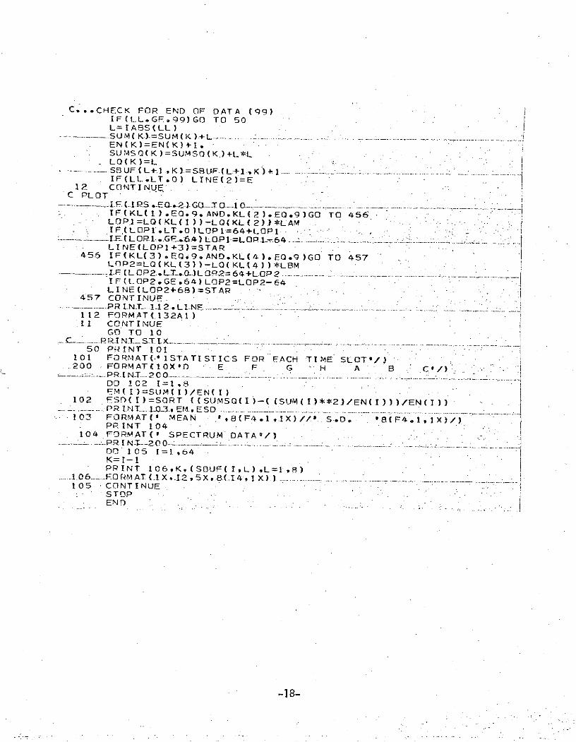
Note that no explicit timing information is given. It is assumed thatOmega data is self-timing, in that a complete sequence of eight measurements is alwaysmade in exactly ten seconds. All eight Omega channels are recorded, even though allstations may not be transmitting. For this flight, lane pairs A-B and B-D were used. Toour knowledge, no other stations were transmitting. In Appendix B, a FORTRAN IV com-puter program is reproduced to show one method for summarizing the flight-test data. Cardcopies of the program and flight-test data reported here are available on request from theauthors. Full documentation of the data reduction sequence appears in R. W. Lilley's,"Omega Flight-Test Data Reduction Sequence ' 4.
-6-
III CONCLUSIONS AND RECOMMENDATIONS
As a result of this flight evaluation, several conclusions may be drawn asto the operation of the receiver base. Several recommendations concerning data-collectiontechnique may be made.
A. Given sufficient signal levels, the receiver base phase-tracks two OmegaLOP's simultaneously, providing the expected navigation-processor inputsignals. Chartrecordings of Omega LOP's A-B and B-D could be interpreted manually, in near real-time,to verify approximate ground position and groundspeed.
In both straight/level flight and during normal maneuvers performed duringtake-off and landing, phase tracking was maintained. The reliable reception of the Norway(A) signal on the outbound flight was a pleasant surprise, as we have had difficulty receivingthis signal in the laboratory. On the return flight, however, in the late afternoon, Norwaywas unusable.
B. The flight evaluation met its objective: that of obtaining commutated digitalphase data for all eight Omega time slots during a test flight whose path was documented forcorrelation with the Omega data.
By means of this Technical Memorandum and data-processing card decks, thephase data will be made available to participants in the Tri-University Program for use innavigation-processor evaluation.
C. For future flight-evaluation activities, several changes should be made inthe data-collection configuration:
1. Collected data on Omega characteristics would be made moremeaningful and easier to use if flight parameters (heading, true airspeed,altitude) could be placed on magnetic tape in real time along with theOmega data. We recommend one flight-path data frame per 10 secondsof Omega data, in an appropriate digital format.
2. Future flights should be planned for data-collection specifically.The flight reported here was a dual-purpose transportation and data-collection flight. For minimal flight time transportation requirements,the flight path is generally not made directly over VOR checkpoints.For flight-evaluation purposes, the use of VOR checkpoints and aVOR/DME or Area Navigation system independent of the pilot's instru-ments allows near-real-time in-flight backup to the digital recordingsystem, allowing meaningful event marks to be inserted manually.
-7-
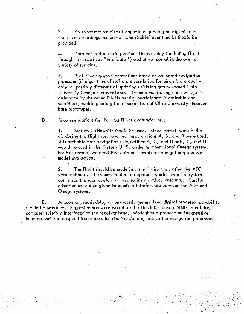
3. An event marker circuit capable of placing on digital tapeand chart recordings numbered (identifiable) event marks should beprovided.
4. Data collection during various times of day (including flightthrough the transition "terminator") and at various altitudes over avariety of terrains.
5. Real-time skywave corrections based on on-board navigation-processor (if algorithms of sufficient resolution for aircraft are avail-able) or possibly differential updating utilizing ground-based OhioUniversity Omega receiver bases. Ground monitoring and in-flightassistance by the other Tri-University participants is desirable andwould be possible pending their acquisition of Ohio University receiverbase prototypes.
D. Recommendations for the next flight evaluation are:
1. Station C (Hawaii) should be used. Since Hawaii was off theair during the flight test reported here, stations A, B, and D were used.It is probable that navigation using either A, C, and D or B, C, and Dwould be used in the Eastern U. S. under an operational Omega system.For this reason, we need live data on Hawaii for navigation-processormodel evaluation.
2. The flight should be made in a small airplane, using the ADFsense antenna. The shared-antenna approach would lower the systemcost since the user would not have to install added antennas. Carefulattention should be given to possible interference between the ADF andOmega systems.
E. As soon as practicable, an on-board, generalized digital processor capabilityshould be provided. Suggested hardware would be the Hewlett-Packard 9830 calculator/computer suitably interfaced to the receiver base. Work should proceed on inexpensiveheading and true airspeed transducers for dead-reckoning aids to the navigation processor.
-8-
IV ACKNOWLEDGEMENTS
Omega Receiver flight tests are performed by the Omega project team underthe Tri-University Program at Ohio University's Avionics Engineering Center. The Directorof the Center is Dr. Richard H. McFarland, who acted as pilot in command during the testflight described here. Ralph Burhans is the Omega Project Engineer, and he served as anobserver and consultant for in-flight navigation. John Abel, an undergraduate studentintern in the Tri-University Program, prepared preflight charts and data, and carried outin-flight navigation tasks. Other Omega team members who aided in preparation of theflight test were graduate student Rick Palkovic and undergraduates Dan Moyer, Dan Ellis,Lee Wright and Dennis Zoulek.
The authors wish to thank each of these team members for their significantcontributions to the success of this test flight.
-9-
V REFERENCES
[11 Chamberlin, Kent A., "Binary Phase Locked Loops for Omega Receivers," paperpresented at the Second Omega Symposium, ION, Washington, D. C.,November 7, 1974..
[21 Lilley, Robert W., "Binary Processing and Display Concepts for Low-Cost OmegaReceivers," paper presented at the Second Omega Symposium, ION, Washington,D. C., November7, 1974.
[3] Burhans, Ralph W., "Phase-Difference Method Offers Low-Cost Navigation Receivers,"Electronics, Vol. 47, pp. 98-105, September 5, 1974.
14] Lilley, Robert W., "Omega Flight-Test Data Reduction Sequence," TechnicalMemorandum (NASA) 12, Avionics Engineering Center, Department of ElectricalEngineering, Ohio University, Athens, Ohio, November, 1974.
-10-
VI APPENDICES
-11-
APPENDIX A
FLIGHT PATH AND OMEGA LOP's
-12-
Page intentionally left blank
TABLE OF EVENTS
OUTBOUND - 10.2 KHZ - OCTOBER 17, 1974
Event No. Time (EDT) Remarks
1 0600:00 Take-off -Albany, Ohio - Magnetic Heading.0600
2 0601:15 Altitude 1000 Feet
3 0604:00 Altitude 2000 Feet
4 0606:00 Altitude 4000 Feet
5 0607:00 Altitude 5000 Feet
6 0608:20 Altitude 6000 Feet
7 0610:00 Altitude 7000 Feet
8 0612:00 Leve I at 9000
9 0619:00 50 Nautical Miles (DME) to EKN
10 0627:45 25
11 0636:15 EKN Alter Heading to 1270 (V38)
12 0655:20 50 Nautical Miles (DME) to GVE
13 0703:30 Period of 25 Nautical Miles (DME) to GVE
14 0713:45 Local Sunrise GVE Alter Heading to 1330 (V38)(at Plane)
455 IF(KL(3).EQ.9,AND.KL(4).EQ.9)GO TO 457LOP2=LQ(KL(3))-LQ(KLf4))*L8M.I.F (.LOP2. L.-T_ 0.)L OP.2= 64+L OP 2IF(LOP2.GE.64) LOP2 =LOP2-64LINE(LOP2+68)=STAR
457 CONTINUE........ PR I.NT-..I.-. 2. L N .... ................ ........ ...112 FORMAT.132AI)11 CONTINUE
GO TO 10C__ipRIN S.X. . .. ........
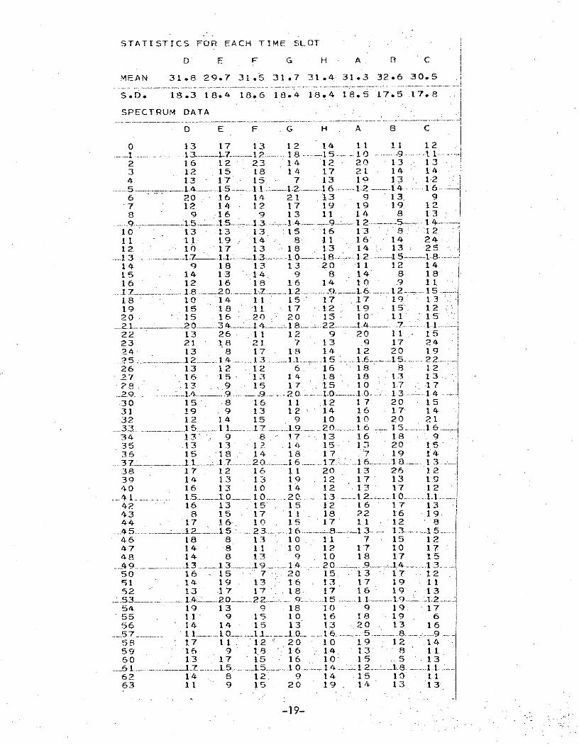
50 PRINT 101101 FORMAT(' ISTATISTICS FOR EACH TIME SLOT'/)200 FORMAT(IOX 0 E F G H A B C'/)
_____P R I N -T-.. 2 0 0 " " - ........DO 102 1=1,8EM( I )=SUM( I )/EN( I)
102 ESD(I)=SQRT ((SUMS (I)--( (SUM(I.)**2)/EN(I)))/EN(I)).. .... .PRINT__03. , EL ., ES D __..................103 FORMAT(' MEAN ',8(F4.1llX)// S.D. o '8(F4.1,IX)/
PRINT 104104 FORMAT(' SPECTRUM DATA'/)
...... -PR I N T--20 .. ...................... .........DO 105 1=1,64K=I-1PRINT 106,K,(SOUF(I,L),L=1,8)
..... 1 ._06 .... O R.AT (...X ,__2,5X,.8(I.4 I X.) ) .... ".....5- " "105 CONTINUE