19
NASA TECHNICAL MEMORANDUM VIRTUAL IMAGE DISPLAY FOR FLIGHT SIMULATION https://ntrs.nasa.gov/search.jsp?R=19710019413 2018-09-14T04:22:10+00:00Z
N A S A T E C H N I C A L
MEMORANDUM
VIRTUAL IMAGE DISPLAY FOR FLIGHT SIMULATION
https://ntrs.nasa.gov/search.jsp?R=19710019413 2018-09-14T04:22:10+00:00Z
NASA TM X-2327 I I I _____i
4. Title and Subtitle 1 5. Report Date I
I VIRTUAL IMAGE DISPLAY FOR FLIGHT SIMULATION
3. Recipient's Catalog No. 1. Report NO.
1 6. Performing Organization Code 1
2. Government Accession No.
7. Author(s) 8. Performing Organizar~on Report No
Bruce C. Ganzle~ A-38 1 1
15. Supplementary Notes
,
9. Performing Organization Name and Address
NASA Ames Resarch Center Moffett Field, Calif. 94035
12. Sponsoring Agency Name and Address
National Aeronautics and Space Administration Washington, D. C. 20546
16. Abstract
10. Work Unit No.
126-63-1 3-03-00-21 --
11. Contract or Grant No I 13. Type of Report and Per~od Coviered
Technical Memorandtirn
14. Sponsoring Agency Code
Simple uncorrected plastic lenses were used to provide a virtual image of a flight scene for use in a flight simulator. A virtual image display provides a realistic impression to the simulator pilot because the image seems to be a substantial distance from the simulator. A number of pilots made landings and takeoffs in a flight simulator to evaluate subjeclivcly a virtual image display. The display consisted of a Schmidt color projector, rear projection screen and a large dia~ncl.cr, loiig focal length, plano-convex plastic lens. Another virtual image display utilizing a color television monitor and two plano-convex plastic lenses was evaluated without formal pilot comment. Various lens parameters were studied ro determine their effect on the flight scene. The conclusion was that simple lenses could be used, with certain limitations, lo obtain a usable virtual image of a flight scene with either a Schmidt projection system or a television monitor.
Displays Virtual Image Lens Flight Simulation
17. Key Words (Suggested by Author(s))
Unclassified - Unlimited
18. Distribution Statement
-
* For sale b y the National Technical Information Service, Springfield, Virginia 22151
I 19. Security Classif. (of this report)
Unclassified
20. Security Classif. (of this page)
Unclassified - E
21. No. of Pages
17
22. Price*
$3 00


SYMBOLS
separation between two lenscs
camera diagonal frame size
lens diameter
focal length
equivalent focal length
focal length of television camera lens system
focal point
eye-to-lens distance (includes thickness of lens)
distance from pilot's eye to first surface of lens
angular magnification
index of refraction
radius of curvature of first and second lens surface
object distance
image distance
lens thickness, normally called sagittal height
radius of lens
viewing width of television monitor or picture width
angular field of view of televisioil camera
horizontal field of view when the object is positioned at the focal point of :he lens
horizontal half-angle of object
horizontal half-angle of image
VIRTUAL IMAGE DISPLAY FOR FLIGHT SIMULATION
Bruce C. Ganzler
Ames Research Center
SUMMARY
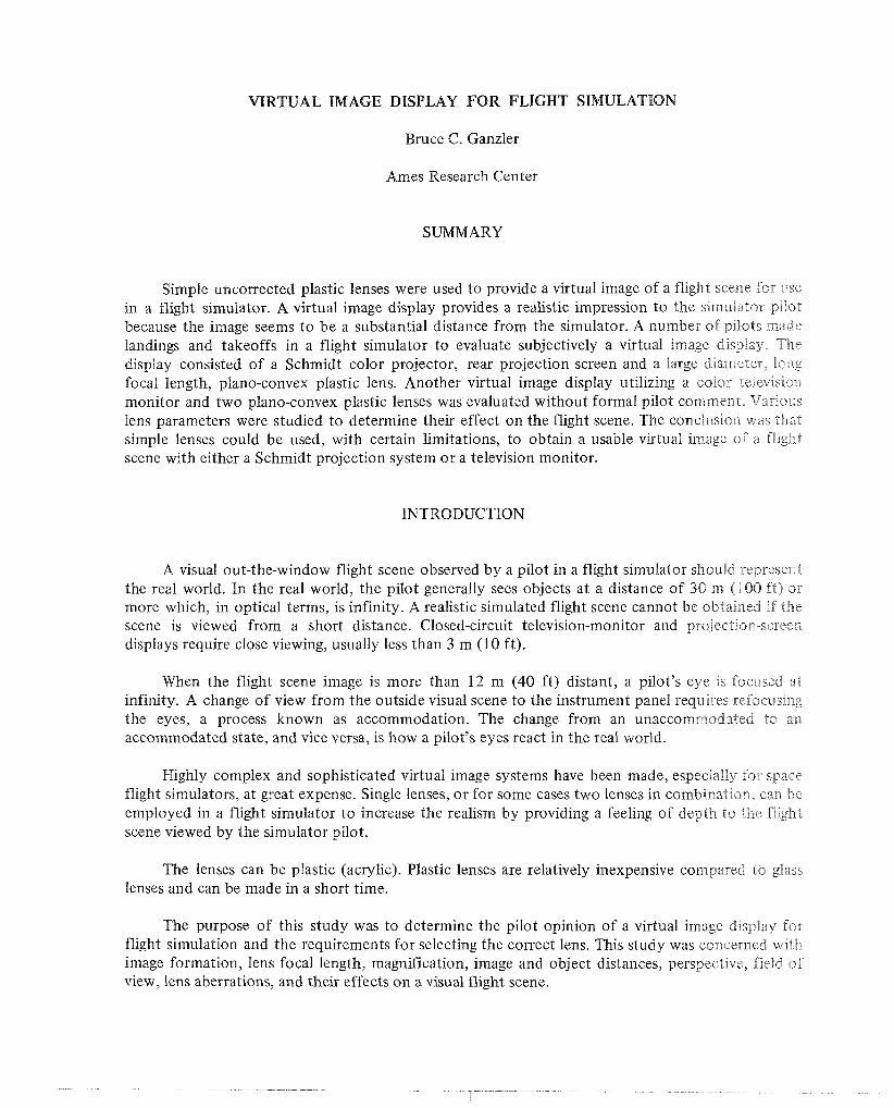
Simple uncorrected plastic lenses were used to provide a virtual image of a flight scene for use in a flight simulator. A virtual image display provides a realistic impression to the sjmulakor p~Bot because the image seems to be a substantial distance from the simulator. A number of pilots made landings and takeoffs in a flight simulator to evaluate subjectively a virtual image display. The display consisted of a Schmidt color projector, rear projection screen and a large diameter, long focal length, plano-convex plastic lens. Another virtual image display utilizing a color televisio~~ monitor and two plano-convex plastic lenses was evaluated without formal pilot comment. Various lens parameters were studied to determine their effect on the flight scene. The conclusiorr was t h a t simple lenses could be used, with certain limitations, to obtain a usable virtual irnzge of a f l~ght scene with either a Schmidt projection system or a television monitor.
INTRODUCTION
A visual out-the-window flight scene observed by a pilot in a flight simulator should represent the real world. In the real world, the pilot generally sees objects at a distance of 30 m (1 00 ft) OF- more which, in optical terms, is infinity. A realistic simulated flight scene cannot be obtained if " r ~ e scene is viewed from a short distance. Closed-circuit television-monitor and projection-scrm displays require close viewing, usually less than 3 m (10 ft).
When the flight scene image is more than 12 m (40 ft) distant, a pilot's eye is focused at infinity. A change of view from the outside visual scene to the instrument panel requires refocusir~g the eyes, a process known as accommodation. The change from an unaccorn~?-eodated to an accommodated state, and vice versa, is how a pilot's eyes react in the real world.
Highly complex and sophisticated virtual image systems have been made, especially for spacc flight simulators, at great expense. Single lenses, or for some cases two lenses in combination-^, can bc employed in a flight simulator to increase the realism by providing a feeling of depth to ihe flighl scene viewed by the simulator pilot.
The lenses can be plastic (acrylic). Plastic lenses are relatively inexpensive con~pared lo glass lenses and can be made in a short time.
The purpose of this study was to determine the pilot opinion of a virtual image display for flight simulation and the requirements for selecting the correct lens. This study was concerned with image formation, lens focal length, magnification, image and object distances, perspective, field of view, lens aberrations, and their effects on a visual flight scene.

SYSTEM CONFIGURATION
The design of a virtual image display for a particular simulator must consider visual presentation of flight data, cab and room geometry, and weights and moments of inertia of equipment which may have to be mounted on a motion simulator. Two systems were used for this study. The first system consisted of a fixed-base simulator, rear projection screen, Schmidt color projector, and a single lens with a focal length of 216 cm (85 in.) and a diameter of 83.8 cm (33 in.). The second system consisted of a motion simulator, color television monitor, and a double-lens combination with an equivalent focal length of 61 cm (24 in.) and a diameter of 63 .5 crn ( 2 5 in.). The image generator was a Plumbicon color camera that viewed a three-dimensional scale model of terrain and runway. Flight dynamics were provided with a general purpose analog computer.
SUBJECTIVE EVALUATION
The first virtual image display was designed so the pilot would observe a flight scene having the same picture perspective as the image generator. Three pilots flew a DC-8 aircraft landing and takeoff problem a number of times in the simulator. They were asked t o write their comments on a prepared questionnaire (table 1).
TABLE 1.- SUBJECTIVE EVALUATION OF VIRTUAL IMAGE FLIGHT SCENE
I i
QUESTIONS 1 ANSWERS I pilot 1 1 pilot 2 I
I . Did you notice any color distortions and, if so, how objectionable were they?
2. Did you rlotice any line distortions (curve or wavy lines) and, if so, how objectionable were they?
3. Were there any head restrictions (laterally and vertically)?
4. brere you conscious of the fact that you were lc~oking through a lens?
5. Did the overall scene appear realistic (feeling that the scene was out a great distance)?
6. Do you [eel the virtual image of the flight scene is an improvement over previous systems?
7. Additional comments?
None serious
NO
YES
YES
~ 1 None
YES, not sure of distance YES, seems to be easier on eyes You have to avoid lights in the cab which might reflect off the lens surface
Not within the normal head area Only when moving the head from side console to forward view Lookedgood
At least as good
Everything satisfactory
VIRTUAL IMAGE LENS PARAMETERS
Virtual Images
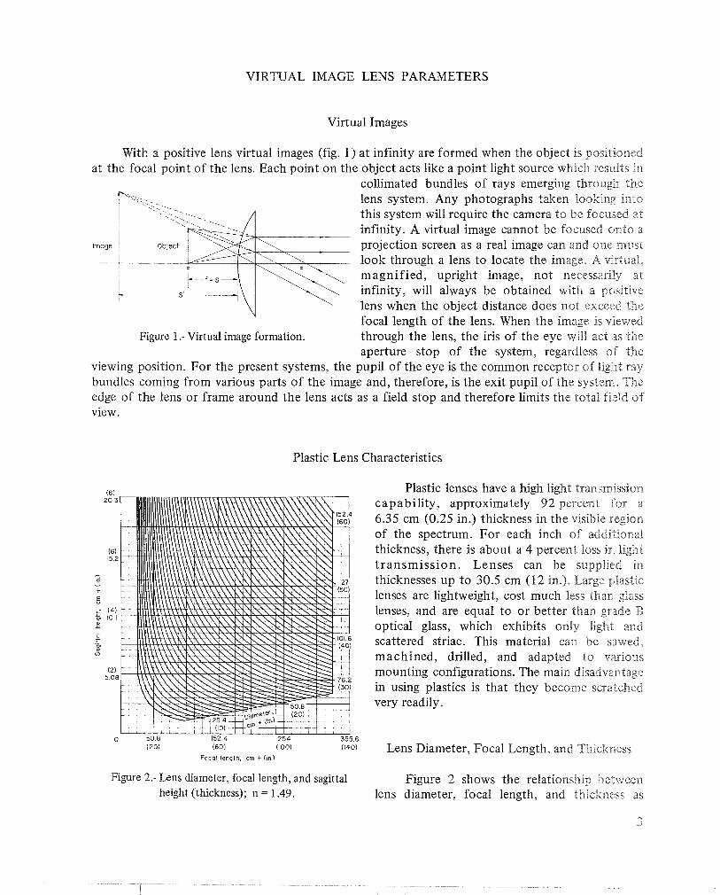
With a positive lens virtual images (fig. 1) at infinity are formed when the objecl IS posit~on~ed at the focal point of the lens. Each point on the object acts like a point light source which results in
collimated bundles of rays emerging through the lens system. Any photographs taken looking into this system will require the camera to be focused at infinity. A virtual image cannot be focused onto a projection screen as a real image can and one must look through a lens to locate the image. A vnrtuaii, magnified, upright image, not necessariky at infinity, will always be obtained with a positive lens when the object distance does not exceed the focal length of the lens. When the image is v~ewed
Figure 1 .- Virtual image formation. through the lens, the iris of the eye will act as the aperture stop of the system, regardless of the
viewing position. For the present systems, the pupil of the eye is the common receptor of light ray bundles coming from various parts of the image and, therefore, is the exit pupil of the system. The edge of the lens or frame around the lens acts as a field stop and therefore limits the total field of view.
Plastic Lens Characteristics
Plastic lenses have a high light transmisslo11 capability, approximately 92 percent for a 6.35 cm (0.25 in.) thickness in the visible region of the spectrum. For each inch of additional thickness, there is about a 4 percent loss in light t ransmission. Lenses can be supplied in thicknesses up to 30.5 cm (12 in.). Large plastic lenses are lightweight, cost much less than glass lenses, and are equal to or better than grade B optical glass, which exhibits only light and scattered striae. This material can be sawed, machined, drilled, and adapted to various mounting configurations. The main disadva~~tage in using plastics is that they become scratched very readily.
0 50 8 152 4 254 355 6 (20) (60) (100) (140)
Focal length, cm t ( ~ n ) Lens Diameter, Focal Length, and Thickness
Figure 2.- Lens diameter, focal length, and sagittal Figure 2 shows the relationship between height (thickness); n = 1.49. lens diameter, focal length, and thickness as
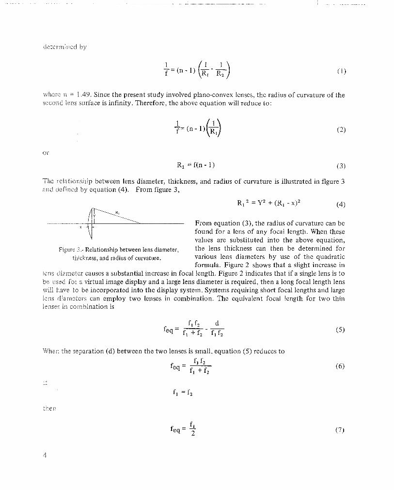
where n = 4.49. Since the present study involved plano-convex lenses, the radius of curvature of the second lens surface is infinity. Therefore, the above equation will reduce to:
The relationship between lens diameter, thickness, and radius of curvature is illustrated in figure 3 and defined by equation (4). From figure 3,
- ,
From equation (3), the radius of curvature can be found for a lens of any focal length. When these
'4 values are substituted into the above equation, Figure 3.- Relationship between lens diameter, the lens thickness can then be determined for
thcltness, and radius of curvature. various lens diameters by use of the quadratic formula. Figure 2 shows that a slight increase in
lens diameter causes a substantial increase in focal length. Figure 2 indicates that if a single lens is to be used for a virtual image display and a large lens diameter is required, then a long focal length lens will have to be incorporated into the display system. Systems requiring short focal lengths and large lens diameters can employ two lenses in combination. The equivalent focal length for two thin lenses in corn bination is
When the separation (d) between the two lenses is small, equation (5) reduces to
If
ther
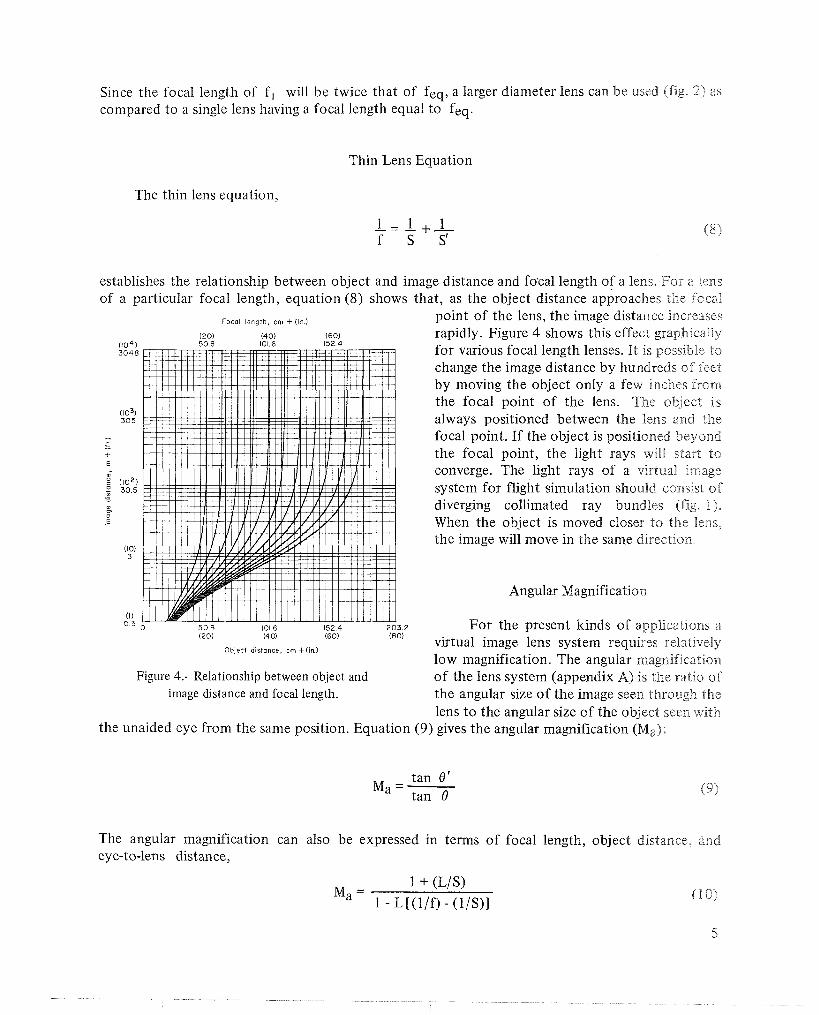
Since the focal length of f, will be twice that of feq, a larger diameter lens can be used (fig. 2) as compared to a single lens having a focal length equal to feq.
Thin Lens Equation
The thin lens equation,
est of
lablishes the relationship between object and image distance and focal length of a lens. For a lens a particular focal length, equation (8) shows that, as the object distance approaches the focal
Focal length, cm + (in.) point of the lens, the image distance increases ( 2 0 ) (40) ( 6 0 ) rapidly. Figure 4 shows this effect graphically 5 0 8 101.6 152.4
for various focal length lenses. It is possible to change the image distance by hundreds of feet by moving the object only a few inches from the focal point of the lens. The object is always positioned between the lens and the focal point. If the object is positioned beyond the focal point, the light rays will start to converge. The light rays of a virtual image system for flight simulation should consist of diverging collimated ray bundles (fig. 1). When the object is moved closer to the Fens, the image will move in the same direction,,
Angular Magnification
For the present kinds of applications a ( 2 0 ) (4 0) (60)
Object distance, cm +(in.) virtual image lens system requires relatively low magnification. The angular magnification
Figure 4.- Relationship between object and of the lens system (appendix A) is the ratio of image distance and focal length. the angular size of the image seen through the
lens to the angular size of the object seen with the unaided eye from the same position. Equation (9) gives the angular magnification (Ma):
tan 8' Ma=-
tan 19
The angular magnification can also be expressed in terms of focal length, object distance, and eye-to-lens distance,
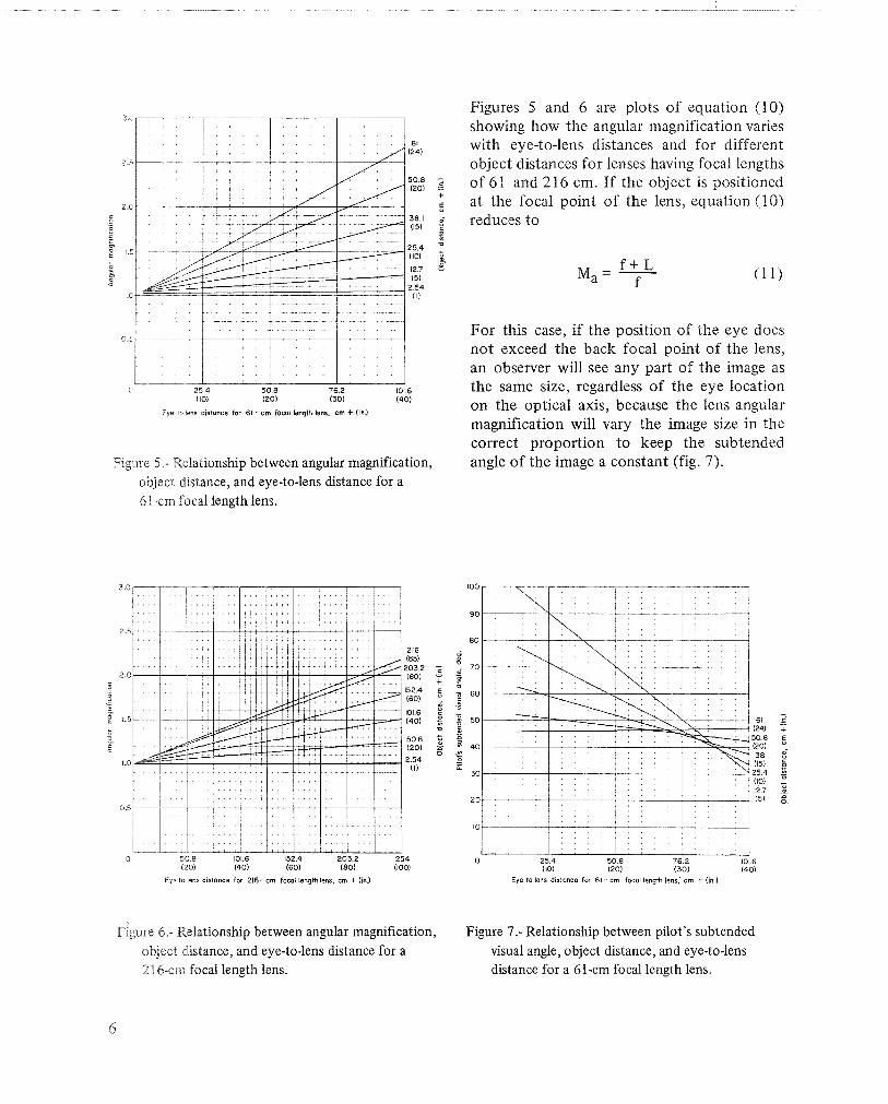
Eye to lens distonce for 61 - cm focol length lens, cm + (In.)
Figure 5.- Relationship between angular magnification, object distance, and eye-to-lens distance for a 61-cm focal length lens.
. . . , . . . . . . . . , . , . . . . . . , . . , . , , . . , . . . , . . . . . .
, . . . . , . . . . . . . . . . . . . . . ,
50 8 101.6 152.4 203.2 2 5 4 (201 (40) (601 (801 (1001
Eye lo lens distonce for 216-cm focal length lens, cm + (in.)
Figures 5 and 6 are plots of equation (10) showing how the angular magnification varies with eye-to-lens distances and for different object distances for lenses having focal lengths of 6 1 and 2 16 cm. If the object is positioned at the focal point of the lens, equation (10) reduces to
For this case, if the position of the eye does not exceed the back focal point of the lens, an observer will see any part of the image as the same size, regardless of the eye location on the optical axis, because the lens angular magnification will vary the image size in the correct proportion to keep the subtended angle of the image a constant (fig. 7).
Eye to lens distonce for 61 - cm focol length lens,' cm + (in.)
Figure 6.- Relationship between angular magnification, Figure 7.- Relationship between pilot's subtended object distance, and eye-to-lens distance for a visual angle, object distance, and eye-to-lens 21 6-crn focal length lens. distance for a 61-cm focal length lens.
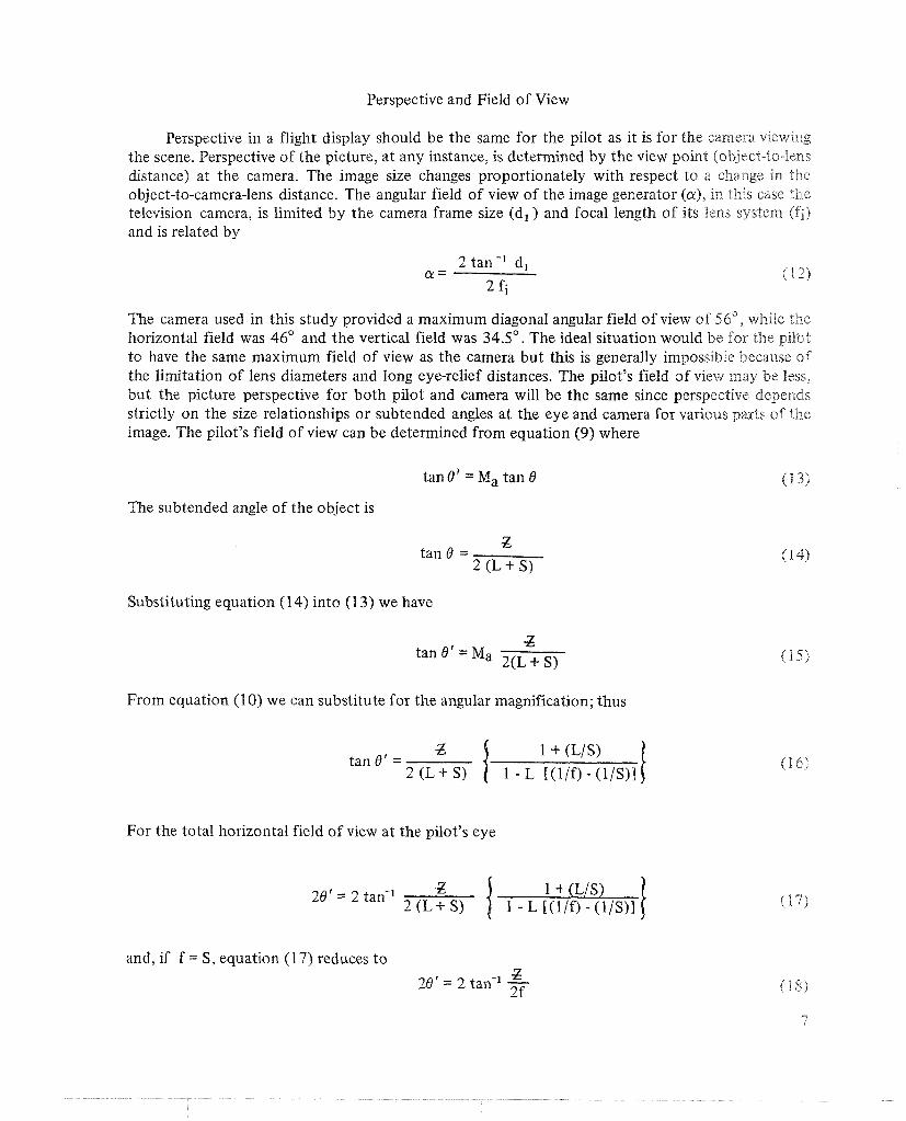
Perspective and Field of View
Perspective in a flight display should be the same for the pilot as it is for the camera viewing the scene. Perspective of the picture, at any instance, is determined by the view point (object-to-lens distance) at the camera. The image size changes proportionately with respect to a change in the object-to-camera-lens distance. The angular field of view of the image generator (a), in this case the television camera, is limited by the camera frame size (dl ) and focal length of its lens system (f j )
and is related by
2 tan -' dl a =
2 fi
The camera used in this study provided a maximum diagonal angular field of view of 56", wlziPe the horizontal field was 46' and the vertical field was 34.5'. The ideal situation would be for the pilot to have the same maximum field of view as the camera but this is generally impossible because of the limitation of lens diameters and long eye-relief distances. The pilot's field of view may be less, but the picture perspective for both pilot and camera will be the same since perspective depends strictly on the size relationships or subtended angles at the eye and camera for various parts of the image. The pilot's field of view can be determined from equation (9) where
tan 8' = Ma tan 8 (13)
The subtended angle of the object is
tan 8 = Z
2 (L+ S)
Substituting equation (1 4) into (1 3) we have
From equation (1 0) we can substitute for the angular magnification; thus
tan 6' = 1 + (L/S)
1 - L l(1lf-l- (1IS)l
For the total horizontal field of view at the pilot's eye
and, if f = S, equation (17) reduces t o -£ 28'= 2 tan-' IT-

Figure '7 uses equation (17) to show how the visual angle varies for various eye-to-lens and object distances for a 61 cm focal length lens. For the special case of f = S, the visual angle of 46' can be considered constant for various eye-to-lens distances.
Focal Length Determination
Figures 8 and 9 show the physical relationship for single and double virtual-image lens systems, respectively. When the object is positioned at the focal point of the lens, the angle (61, whch IS the maximum horizontal field of view from the lens position, is equal to the total horizontal field of view of the image from the pilot's eye position. From equation (18) we have
Schmidt Color Projector
Rear Projection Screen
Lens
Pilol
It is obvious from equation (1 8) that the focal length of the required simulaTor lens can be determined if the horizontal field of view and object size are known. The equation for the focal length (f) based on equations (18) and (1 9) can be written
Color Television Monitor
Lens Combinot~on
Pilot
Figure 8.- Single lens virtual image system. Figure 9.- Double lens virtual image system.
8
Z f =
2 tan (612)
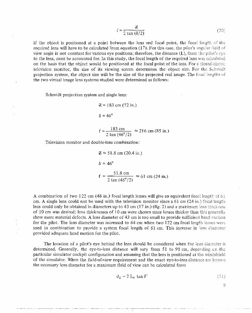
If the object is positioned at a point between the lens and focal point, the focal length of the required lens will have to be calculated from equation (17). For this case, the pilot's angular field of view angle is not constant for various eye positions; therefore, the distance (L), from the p~lot's eye to the lens, must be accounted for. In this study, the focal length of the required lens was calculated on the basis that the object would be positioned at the focal point of the lens. For a closed-circuit television monitor, the size of its viewing screen determines the object size. For the Schmedl projection system, the object size will be the size of the projected real image. The focal lengths of the two virtual image lens systems studied were determined as follows:
Schmidt projection system and single lens:
Z = 183 cm (72 in.)
6 = 46"
f = 183cm %216cm(85in . ) 2 tan (46"/2)
Television monitor and double-lens combination:
Z x 5 1.8 cm (20.4 in.)
51.8 cm f = x 6 1 cm (24 in.)
2 tan (46"/2)
A combination of two 122 cm (48 in.) focal length lenses will give an equivalent focal length 01 6 B cm. A single lens could not be used with the television monitor since a 61 cm (24 in.) focal iiength lens could only be obtained in diameters up to 43 cm (17 in.) (fig. 2) and a maximum Pens thickness of 10 cm was desired; lens thicknesses of 10 cm were chosen since lenses thicker than this generally show more material defects. A lens diameter of 43 cm is too small to provide sufficient head motion for the pilot. The lens diameter was increased to 64 cm when two 122 cm focal length lenses were used in combination to provide a system focal length of 61 cm. This increase in lens diameter provided adequate head motion for the pilot.
The location of a pilot's eye behind the lens should be considered when the Pens diameter Is determined. Generally, the eye-to-lens distance will vary from 5 1 to 9 1 cm, depending on the particular simulator cockpit configuration and assuming that the lens is positioned at the windshield of the simulator. When the field-of-view requirement and the exact eye-to-lens distance are kno~wxl the necessary lens diameter for a maximum fleld of view can be calculated from
d, = 2 L, tan 8' (21)

When possible, it is desirable for the lens diameter to be larger than required for the maximum field of view since the lens may have to be cut for mounting and masked to simulate the framework of the cockpit windshield.
IMAGE DEFECTS AND OPTICAL CONSTRAINTS
Simple, uncorrected lenses exhibit many aberrations that affect the quality of the image. Coma and spherical aberrations vary with the square of the aperture while astigmatism and i:umature of image vary with the square of the image height. Coma and lateral color vary directly with the image height, while distortion varies with the cube of the image height.
Moving the object closer to the lens will minimize many lens aberrations but changing the object distance will depend on the required field of view and image distance. Moving the object closer to the lens, then, results in less angular magnification and significantly reduced image distance. Mso, the image size is less because of the reduced angular magnification; consequently, some of the above-mentioned aberrations will be reduced.
\Vhen s~ngle plano-convex lenses are used, the convex surface should face the object since this will minimize spherical aberrations (i.e., refraction of light rays in the outer portion of the lens compared to rays near the optical axis will be less). Longer focal length lenses have to be used with a color Schmidt projector since the projector requires at least 335 cm (1 1 ft) "throw distance" to properly converge and register the colors from its three cathode ray tubes. Picture size is thus much larger than that produced by a TV monitor and, in order to maintain the proper TV camera perspective, Long focal length lenses have to be used so the projection screen can be positioned the necessary distance from the pilot's eyes.
For the double lens system, the convex sides of the two lenses should face each other. Pincushion distortion and lateral color are problems with this system.
NevertheBess, the resulting image from each of the systems studied here did provide an adequate flight scene for simulator aircraft landing and takeoff. The central area of the virtual image (approximately one-third of the lens diameter) appeared to be in sharp focus. The remaining portion of the image became progressively worse out to the edge of the lens. Normally, the runway area is approximately centered on the central area of the lens. More peripheral details, such as trees, s l ~ ~ b s , and mountains, are generally in the area that is slightly out of focus. Various pilots who have flown the simulators with the virtual image display have not complained of this condition, and f rox all indications it has not affected their landing and takeoff performances.
Table 2 shows some of the advantages and disadvantages between the two display systems ~rsed lor this study.

TABLE 2.- SINGLE LENS S C m I D T VERSUS DOUBLE LENS TV MONITOR COLOR DISPLAY -
Schmidt - single lens - projection screen 1. Lens system shows less aberrations (not bothered as much by pincushion distortion and lateral
color) 2 . Larger lens diameters are available (head motion, without image shift, much greater) 3. Higher TV resolution (approximately 30 to 50 TV lines) 4. Absence of shadow mask CRT tube structure that contributes to the degradation of the image
TV monitor -- double lens 1. Higher contrast 2. Easier to register colors and maintain registration 3. Cost from 10 to 25 times less than various Schmidt color projectors 4. Wgher reliability - easier to maintain 5. Less weight - especially attractive for motion simulators 6. Separate displays as well as side windows can be provided for both pilot and copilot 7. Higher brightness -cabin lights can be left on to simulate a daytime condition inside the sim~dalor 8. Setup time is negligible compared to a Schmidt
CONCLUSIONS
A virtual image system employing simple uncorrected plastic lenses can be utilized in a satisfactory manner in simulating a realistic flight scene. Various lens parameters must be closely scrutinized, however, in order t o obtain an optimized virtual image lens system for a particular flight simulator. A virtual image of a flight scene using television monitors requires two 1- ~nse s so that large diameters can be used t o allow the pilot adequate head motion. If separate virtual image systems are desired for both pilot and copilot, then television monitors become attractive because of their small size and relative ease in simultaneous control.
Ames Research Center National Aeronautics and Space Administration
Moffett Field, Calif., 94035, April 1, 1971
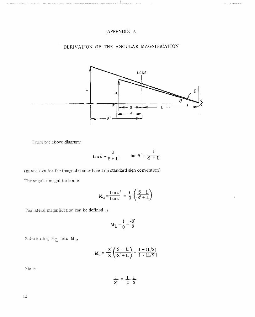
APPENDIX A
DERIVATION OF THE ANGULAR MAGNIFICATION
From the above diagram:
0 I tan 0 =- tan 0' =
S + L
(minus sign for the image distance based on standard sign convention)
The angular magnification is
The la~eral magnification can be defined as
Siabstituting ML into Ma,
Since

then
If f = S then
BIBLIOGRAPHY
Anon.: Technical File 102: Acrylic Optics. Applied Products Corporation, Horsham, Pennsylvania.
Anon.: Technical File 103: Acrylic Optics Comes of Age. Applied Products Corporation, Horsham Pennsylvania.
Jacobs, Donald H.: Fundamentals of Optical Engineering. McGraw-Hill Book Company, Inc., 1943.
Jenkms, F. R.; and Whte, H. E.: Fundamentals of Optics. McGraw-Hill Book Company, 1957.
Mauro, J. A.: Optical Engineering Handbook. General Electric Company, Syracuse, N. Y., 1966.
Ogle, Kenneth N.: Optics. Charles C. Thomas, Springfield, Ill., 1961.
FllR6T MAIL
' I , , * ' I ,' t
: ! j I 1 " 1 I, -' 1 1 ! , :!: 8 , ii 8 ' ,' :,
if u n ~ d w . E ~ r c mmm' polc.1 MvmmI) Ekrp~=@
- ,
' I c a d u ~ d ra o ~ ; ro EW~'&W of pbmewsaar dw tk &r~o~$&
' r h d p u d e f & ~ &B w&rt prrB I B! is/a.r~?&E.te mc(~*g d#$
--MAWQHAL Amow~vzria AND SPACE Act w I95B
NTIPIC AND TECHNZCAL PWEEUCA16"TONS
rnBUC&rnQNS: Iniotmtidn an MII&@ . by W M that m y BB bf ~ i n s l % r
interest in emme1 m a d asher r n 4 . e r o . b ~ e ' * applicrtion- Rublimrim include T K ~ &irb
"SS~DO~W Utaiah R e p 1 9 md T d a d ~ Survqs.
' , I sClENTlFlC AND TECHNICAL INFORMATI~W OIFFIC~


