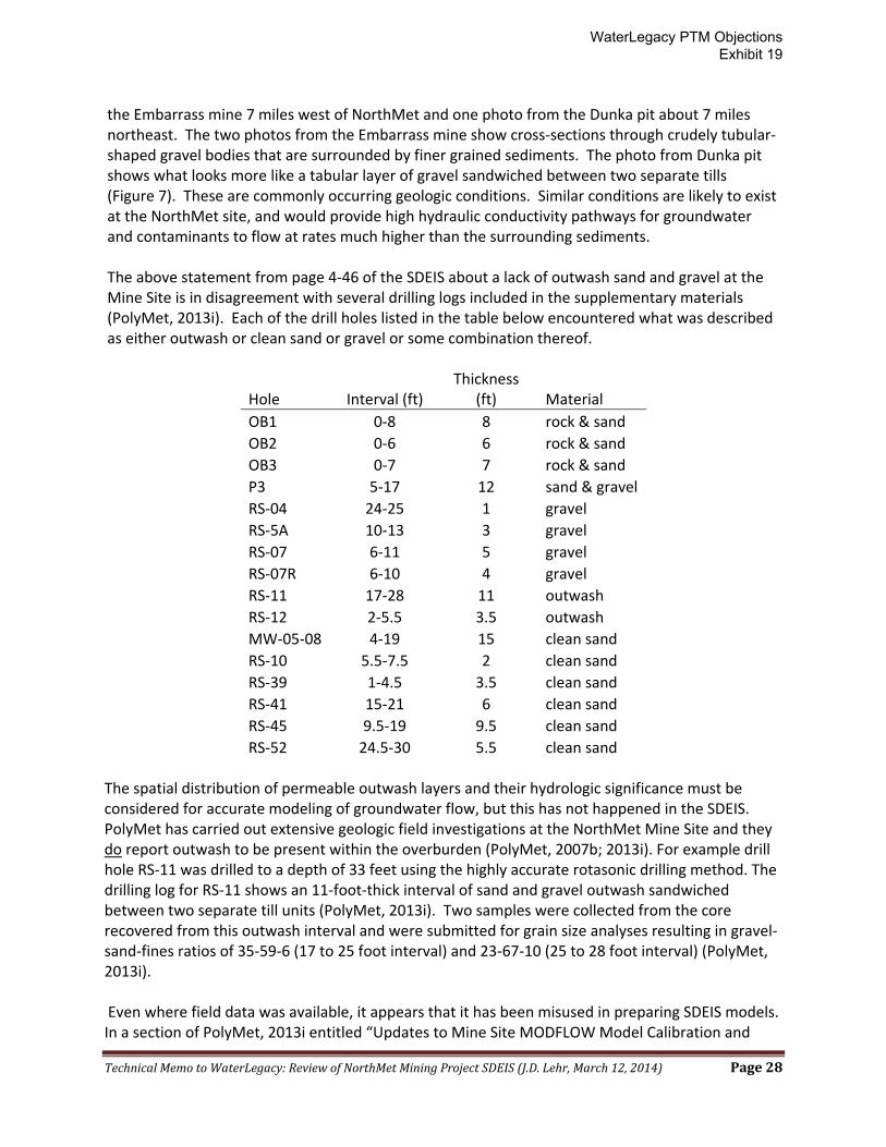
TECHNICAL MEMORANDUM Summary of Comments Resulting from Review of NorthMet Mining Project and Land Exchange Supplemental Draft Environmental Impact Statement Prepared for: Paula Maccabee Counsel/Advocacy Director for WaterLegacy St. Paul, Minnesota Prepared by: J.D. Lehr Professional Geologist Lutsen, Minnesota 1 March 12, 2014 1.0 BACKGROUND This document is prepared to assist WaterLegacy in formulating meaningful comments on the PolyMet NorthMet SDEIS in a scientifically accurate manner. This memorandum focuses on issues pertaining to bedrock and surficial geology and the implications these subject areas have on groundwater flow and the possibility for interaction between groundwater occurring in surficial materials and groundwater within the bedrock. A series of 16 individual PDF documents representing the entire SDEIS were downloaded from the Minnesota Department of Natural Resources (“MDNR”) NorthMet Mining Project website. A 2-DVD set of supplemental reference materials dated November 2013 was provided by Bill Johnson at MDNR. These two sets of documents comprise the materials available for the purposes of this review. Because of the sheer volume of material contained in the SDEIS and the DVD set references - more than 64,000 pages – a complete and thorough review of all SDEIS materials was not possible considering time constraints. Rather, the sections of the SDEIS document itself dealing with geology were carefully reviewed, but only certain portions of the supporting reference materials could be reviewed in detail. The subject of geology is of fundamental importance to any proposed mining project. For example, a thorough understanding of the mine site bedrock geology leads to models that accurately predict variations in ore grade and allow for the visualization of the complex three-dimensional structural relationships that exist between the various categories of ore and waste rock that that will be mined. During mining operations huge volumes of earth materials consisting of rock and overburden must be removed and transported efficiently and stockpiled without generating hazards such as instable slopes or impoundments, acid mine drainage and mobilization of toxic levels of metals. Bedrock and surficial sediments are the containers for groundwater and the 1 Full mailing address included in Appendix A WaterLegacy PTM Objections Exhibit 19
Transcript
TECHNICAL MEMORANDUM Summary of Comments Resulting from Review of NorthMet Mining Project and Land Exchange Supplemental Draft Environmental Impact Statement Prepared for: Paula Maccabee
Counsel/Advocacy Director for WaterLegacy St. Paul, Minnesota
Prepared by: J.D. Lehr Professional Geologist Lutsen, Minnesota1
March 12, 2014 1.0 BACKGROUND This document is prepared to assist WaterLegacy in formulating meaningful comments on the PolyMet NorthMet SDEIS in a scientifically accurate manner. This memorandum focuses on issues pertaining to bedrock and surficial geology and the implications these subject areas have on groundwater flow and the possibility for interaction between groundwater occurring in surficial materials and groundwater within the bedrock. A series of 16 individual PDF documents representing the entire SDEIS were downloaded from the Minnesota Department of Natural Resources (“MDNR”) NorthMet Mining Project website. A 2-DVD set of supplemental reference materials dated November 2013 was provided by Bill Johnson at MDNR. These two sets of documents comprise the materials available for the purposes of this review. Because of the sheer volume of material contained in the SDEIS and the DVD set references - more than 64,000 pages – a complete and thorough review of all SDEIS materials was not possible considering time constraints. Rather, the sections of the SDEIS document itself dealing with geology were carefully reviewed, but only certain portions of the supporting reference materials could be reviewed in detail. The subject of geology is of fundamental importance to any proposed mining project. For example, a thorough understanding of the mine site bedrock geology leads to models that accurately predict variations in ore grade and allow for the visualization of the complex three-dimensional structural relationships that exist between the various categories of ore and waste rock that that will be mined. During mining operations huge volumes of earth materials consisting of rock and overburden must be removed and transported efficiently and stockpiled without generating hazards such as instable slopes or impoundments, acid mine drainage and mobilization of toxic levels of metals. Bedrock and surficial sediments are the containers for groundwater and the
1 Full mailing address included in Appendix A
WaterLegacy PTM Objections Exhibit 19
Technical Memo to WaterLegacy: Review of NorthMet Mining Project SDEIS (J.D. Lehr, March 12, 2014) Page 2
platform upon which mine process waters interact with groundwater and surface waters such as streams, lakes and wetlands. Understanding the spatial variability of the various geologic materials and their degree of hydrologic interconnectivity are fundamental to understanding potential impacts to groundwater and surface water resources that result from mining. There is considerable value in understanding the locations of highly permeable zones such as layers of unconsolidated sand and gravel, bedrock fault zones and other areas of fractured bedrock that have the potential to transmit groundwater at much higher velocities than surrounding materials. A confident understanding of the location of these potential groundwater conduits is required before effective engineering controls can be designed, constructed and operated to mitigate potential hazards. A mine plan based on sound geology leads to fewer operational problems as well as fewer negative environmental effects. Lack of in-depth knowledge of mine site geology or a misunderstanding of certain aspects of mine site geology will have several negative effects. Some these negative effects create risks related to operations, for example unexpected variation in ore grade or issues with high wall safety, but they also include risks relating to the ability to accurately predict the environmental effects of a mining project. An overly simple or incorrect understanding of mine site geology greatly limits the ability to accurately predict the behavior of groundwater which gives rise to the inability to effectively design and construct engineered pollution mitigation measures and the inability to accurately forecast the financial resources necessary to operate them for the required length of time. Simply stated, geology forms the foundation that so many other aspects of the proposed NorthMet project are based upon. The geology presented in the SDEIS should be detailed, scientifically accurate, up-to-date and robust. My first independent geologic field research was carried out in the vicinity of NorthMet 30 years ago. This field work was part of my graduate research that involved mapping the surficial geology of a portion of the eastern Mesabi Range area, including parts of the NorthMet Mining Project area. One additional aspect this research dealt with studying the relationships between bedrock type, bedrock structures such as faults and fractures and surficial landforms in northeastern Minnesota (Lehr, 2000). In the early 1990’s I was co-organizer of a field conference held in the area of the eastern Mesabi Range and adjacent parts of the Superior National Forest that was attended by over 100 scientists from around the country. A synopsis of the surficial geology of northeastern Minnesota was published in a fieldtrip guidebook prepared for this field conference (Lehr and Hobbs, 1992). I have continued to map surficial geology across all of northeastern Minnesota, especially over the past few years since the release of high-resolution LiDAR data for these areas. A more complete summary of my qualifications to carry out this review are presented in my Curriculum Vitae attached at the end of this memo. The comments below relating to those sections of the SDEIS that deal with geology are divided into five main sections by topic. The first section (2.0) covers the subject of bedrock fracturing at both the Mine Site and Tailings Basin Site and the implications bedrock fractures may have on groundwater flow. The second section (3.0) of this report contains a review of those sections of the SDEIS relating to surficial geology of both the Mine Site and Tailings Basin Site and its hydrologic significance. The third section (4.0) contains comments on bedrock geology that don’t fit in the bedrock fracture section and the fourth section (5.0) contains a short discussion of the potential for
WaterLegacy PTM Objections Exhibit 19
Technical Memo to WaterLegacy: Review of NorthMet Mining Project SDEIS (J.D. Lehr, March 12, 2014) Page 3
hydrologic connections to exist between the surficial aquifer and the bedrock aquifer. The fifth section (6.0) contains additional comments that don’t fit into any of the previous sections. Some concluding remarks are presented in section 7.0. A list of references cited is included in section 8.0. Two appendices are included with this report. Appendix A contains J.D. Lehr’s CV and Appendix B contains certain figures referenced in this report. 2.0 BEDROCK FRACTURING For projects such as the NorthMet Mine proposal a sound understanding the three dimensional geometry of bedrock fractures and their hydrogeologic properties will contribute to more accurate predictions of groundwater flow direction, flow rates and volumes. Prior to presenting a general discussion of bedrock fracturing below, a few technical terms used in the study of bedrock fractures are defined below.
“Fracture, a term from geology, refers to a surface along which a break has occurred in bedrock. An open fracture is a fracture with measureable distance (aperture) between sides of the fracture. A fault is a fracture along which there is displacement parallel to the fracture surface. Points originally adjacent on either side of the fracture are displaced. If there is no displacement between adjacent points on opposite sides of the fracture, the fracture is called a joint.” (Clark, et al, 1996, p. 2)
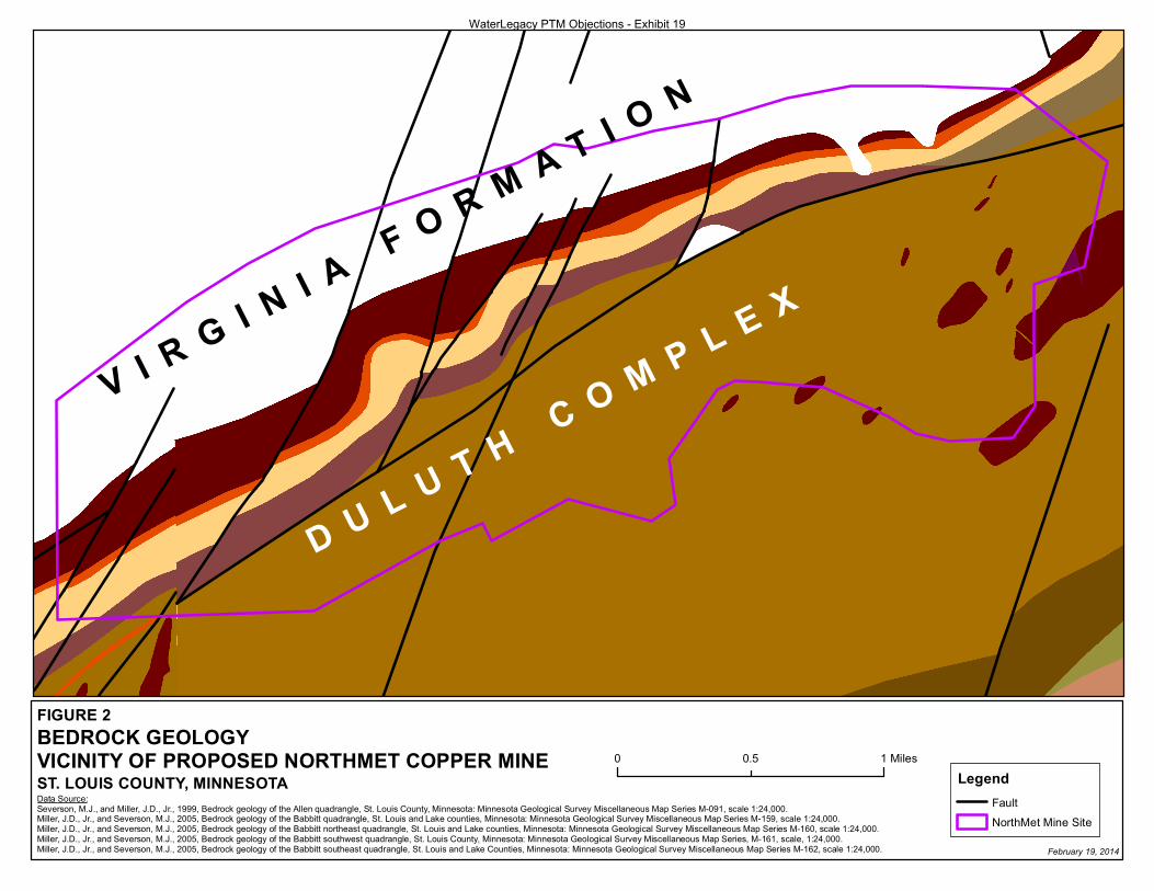
In general, the SDEIS gives only a cursory and simplistic treatment to the role bedrock fractures play in the transmission of groundwater at the NorthMet Mine Site and at the Tailings Basin. The entire treatment of bedrock fracturing at the Mine Site is presented on a single page (page 4-45). In many places within the SDEIS important statements made relating to bedrock fracturing are either unreferenced, inaccurately referenced or otherwise unsupported by data tables, figures or maps. Perhaps of greater concern are the numerous instances within the SDEIS where statements made related to the hydrologic significance of bedrock fractures blatantly misrepresent what the cited author(s) stated. Some of these particular instances will be highlighted below. The simplistic approach the SDEIS takes in its treatment of the role of bedrock fractures in groundwater flow is underscored by Figure 3.2-28 of the SDEIS. This figure shows a conceptual cross section of the Tailings Basin, the geologic materials beneath and the groundwater containment system that is proposed to be constructed around its perimeter. This figure portrays the bedrock that occurs beneath the Tailings Basin as an “assumed no-flow boundary”. The implications of this are that groundwater flow through bedrock at the Tailings Basin is so insignificant that it can be conceptually ignored. If this assumption were accepted achieving the collection of 90 percent or more of contaminated groundwater would sound reasonable; however this rather critical hydrogeologic assumption is not supported by either data or cited references within the SDEIS. Recent geologic mapping by the Minnesota Geological Survey shows a fault beneath the existing Tailings Basin and proposed Hydrometallurgical Residue Facility (“HRF”) (Figure 1). Numerous other faults are mapped in close proximity (Jirsa et al, 2005; Jirsa et al, 2011; Jirsa et al, 2012). The hydrologic significance of these faults is unknown at this time because the SDEIS did not address them.
WaterLegacy PTM Objections Exhibit 19
Technical Memo to WaterLegacy: Review of NorthMet Mining Project SDEIS (J.D. Lehr, March 12, 2014) Page 4
Numerous recently-developed tools and technologies are commonly used in combination with more traditional mapping methods to successfully evaluate the hydrologic properties of bedrock fractures. Evaluation of bedrock fractures and their hydrologic significance often begins with desktop research of linear trends that appear on imagery. The fairly recently released LiDAR topography datasets for northeastern Minnesota are a tremendously useful public-domain data source available for use during the initial phases of bedrock fracture studies. LiDAR data are especially useful in the densely forested areas such as northern Minnesota because topographic details beneath the pervasive cover of vegetation are revealed. The merging of LiDAR data with other datasets such as aeromagnetic data for example has proven useful in mapping bedrock fractures elsewhere (Golder Associates, 2010). Following up desktop research with traditional field mapping techniques further contributes to the understanding of bedrock fractures by recording the orientation of fractures traces at the land surface and the noting the character of the near-surface fracture surfaces and apertures. In addition to traditional drill core logging, a number of borehole geophysical techniques can also be used to map bedrock fractures and characterize their hydrologic properties. These techniques include temperature logging, acoustic logging, resistivity, gamma and caliper logging and even optical (TV) logging of boreholes. A variety of traditional surface geophysical methods can also be employed to map and characterize bedrock fractures. These include ground penetrating radar, electrical resistivity and seismic surveys. Of course various borehole hydrologic procedures such as pump tests, packer tests, slug tests and tracer tests have direct application in the study of the hydrology of bedrock fractures (Golder Associates, 2010). Apparently none of these techniques were employed in the SDEIS process to identify fractures or assess groundwater flow through fractured bedrock. This seems like a major omission, resulting in unsupported assumptions and inadequate information regarding groundwater flow at both the Mine Site and Tailings Basin. 2.1 Bedrock Fracturing – Mine Site The rationale presented in the SDEIS in support of a rather simplified view of bedrock fracturing at the Mine Site begins at the top of page 4-45. Instead of describing the distribution of known fractures at the Mine Site and reporting on their hydrologic properties, this section instead uses anecdotal comparisons to downplay the significance of bedrock fractures at the Mine Site. The page leads off with the following three sentences.
“Concerns have been raised that fractures, including faults and fracture zones, may exist that could permit transmission of groundwater through the bedrock over distances of thousands of feet. Such features have been identified elsewhere on the Canadian Shield, but have been genetically associated with tectonic events occurring more than 1,600 million years ago (Farvolden et al. 1988; Douglas et al. 2000; Rouleau et al. 2003). These events would not be relevant to the Duluth Complex as they predate its emplacement during the formation of the Mid-Continent Rift approximately 1.1 billion years ago.” (SDEIS, p. 4-45)
This quote implies that the rocks of the Duluth Complex do not “contain faults and fracture zones that could transmit ground water through bedrock over distances of thousands of feet” because
WaterLegacy PTM Objections Exhibit 19
Technical Memo to WaterLegacy: Review of NorthMet Mining Project SDEIS (J.D. Lehr, March 12, 2014) Page 5
they are simply too young. Neither Farvolden et al (1988), Douglas et al (2000) or Rouleau et al (2003) make statements that support the SDEIS’ assertion that the degree of faulting and fracturing of rocks is in any way related to the age of the rocks. On the contrary, one pertinent remark made by Farvolden el al (1988) is that “mineral deposits on the Canadian Shield are commonly associated with geologic anomalies, in particular contact zones, faults or fracture zones” (emphasis added). The rocks of the Duluth Complex are indeed fractured and faulted. Faults are documented in several recently published geologic maps of the NorthMet property and surrounding areas (Severson and Miller, 1999; Miller and Severson, 2006a, 2006b, 2006c, 2006d; Jirsa et al, 2005; Jirsa et al, 2011; Jirsa et al, 2012) (Figure 1; Figure 2). This is also common knowledge amongst geologists working in the area. Even PolyMet’s own geologists describe the rocks at the Mine Site as being fractured and faulted – they specifically mention 14 separate faults zones that transect the Mine Site (PolyMet, 2007b) (Figure 2). Some of the SDEIS’ supporting literature also correctly characterizes the bedrock at the Mine Site as fractured in certain places. The presence of fractures in this part of the Duluth Complex has been known since the Copper-Nickel Study days. Siegel and Ericson (1980) reported that “fractures and joints in the Duluth Complex may extend to considerable depths but are more extensive in the upper 200 to 300 feet of the bedrock” (p. 7). In certain places, the SDEIS acknowledges the presence of fractured bedrock at the Mine Site.
“The geologic and hydrogeologic settings of the Mine Site and the analog sites are fairly similar with a thin veneer of heterogeneous unconsolidated deposits underlain by fractured bedrock.” (SDEIS, p. 5-243)
“The hydrogeologic setting of the Partridge River watershed consists of a thin veneer of heterogeneous unconsolidated deposits (glacial till) underlain by fractured bedrock (Duluth Complex in most of the Mine Site and Virginia Formation in the northern portion of the Mine Site).” (SDEIS, p. 4-149)
The SDEIS, in other places, acknowledges that groundwater flow through bedrock occurs through fractures or other secondary porosity features.
“The bedrock has low primary permeability, so groundwater flow within the bedrock is through fractures or other secondary porosity features.” (SDEIS, p. 4-149)
Yet, the SDEIS downplays the hydrologic significance of bedrock fractures and does not seem to include groundwater flow through fractures in its seepage calculations. Discussion of the hydrologic significance of bedrock fractures at the Mine Site continues on page 4-45 with the following quote:
“Foose and Cooper (1979; 1980) appear to have provided the only published work specifically looking at the presence of fracturing and faulting in the Duluth Complex. They identified numerous faults and fractures in their surface mapping of the Harris Lake area, as is commonly found in the surface exposures of crystalline bedrock. However, they described the most extensive faults—those most likely to be long distance groundwater conduits—as being largely filled with gouge. They also conclude that most of the faults and fractures formed early and at depth, during emplacement of the Duluth Complex, and were not related
WaterLegacy PTM Objections Exhibit 19
Technical Memo to WaterLegacy: Review of NorthMet Mining Project SDEIS (J.D. Lehr, March 12, 2014) Page 6
to post-emplacement deformation, which would have more likely resulted in fractures open to groundwater flow.” (SDEIS, p. 4-45)
First, there are no Foose and Cooper references listed in the SDEIS from either 1979 or 1980, so it is assumed the references and conclusions in this paragraph are from Foose and Cooper 1978 and 1981 which are cited in the list of references. Again, these statements made relating to bedrock fractures are not supported by the references cited in the SDEIS. Neither of the two Foose and Cooper papers report that “the most extensive faults are largely filled with gouge.” Their only mention of fault gouge in these two papers is that they used its presence to trace fault zones in the field. Neither paper discusses distance groundwater may flow through faults and fractures in the Duluth Complex - in fact neither mention groundwater flow at all. The main purpose of Foose and Cooper’s research was to demonstrate the usefulness of detailed mapping of igneous stratigraphy towards mapping fractures in what at first glance looks like entirely homogeneous rock. The SDEIS uses Foose and Cooper’s characterization of the faults in their study area as “forming early and at depth” as somehow contributing to lesser hydrologic significance than fractures that might have formed later or at shallower depths. However, no such claims are made in the Foose and Cooper papers and no data are presented to support this assertion in the SDEIS. The sections of the SDEIS describing bedrock fractures rely mostly on references that are quite old while failing to reference vast amounts of more recent geologic data and scientific literature directly relevant to assess hydrologic role of bedrock fractures at NorthMet. PolyMet and its predecessors have acquired detailed site-specific knowledge of the geology of the NorthMet ore deposit. The NorthMet deposit mine plan and other critical documents and datasets, including all geologic data have been reviewed by what are essentially external auditors (AGP Mining Consultants Inc.) who prepared the 43-101 Technical Report for the NorthMet project (Desautels and Zurowski, 2012) on PolyMet’s behalf. Quality geologic data have been collected over the years from the NorthMet area that could have been used to present a more detailed and realistic understanding of the bedrock fractures known to exist at both the Mine Site and the Tailings Basin than what is presented in the SDEIS. One specific example of the type of data relevant to the nature of bedrock fracturing that have been collected but are not presented in the SDEIS is the RQD table from PolyMet’s drilling database (PolyMet, 2007b). RQD is an acronym for “rock quality designator” and it represents a simple quantitative measure of the degree of rock fracturing that is calculated from basic measurements taken from drill core. Results of RQD calculations are reported as a percentage that ranges from 0 (more fractured) to 100 (less fractured). PolyMet reports the average of all RQD data for Duluth Complex rocks at NorthMet to be 93% (Desautels and Zurowski, 2012) to 94% (PolyMet, 2007b) - a number that by itself suggests relatively few fractures overall. However because it is an average, a certain portion of the RQD data would be less than 93 or 94%. Those cored intervals with RQD values less than 93% would indicate intervals that are more fractured than average – an important hydrogeologic characteristic to understand. More detail from the RQD table would allow for a greater understanding of the spatial variability of bedrock fractures. Table 10-1 from Desautels and Zurowski (2012) below shows average RQD values from NorthMet broken down by rock unit. Note that units 1 to 7 are Duluth Complex rock units with unit 1
WaterLegacy PTM Objections Exhibit 19
Technical Memo to WaterLegacy: Review of NorthMet Mining Project SDEIS (J.D. Lehr, March 12, 2014) Page 7
stratigraphically the lowermost and unit 7 the uppermost. The RQD values presented for each rock unit represent the average of a large number of individual RQD measurements. For example 4,194 individual RQD measurements were taken from drill core assigned to unit 1 to arrive at an average RQD of 91.8 for that unit.
Table 10-1: Summary of Core Recoveries and RQD Measurements (includes all drilling through summer 2007)
Table from (Desautels and Zurowski, 2012) It is the lower RQD percentages in this dataset along with an understanding of their spatial distribution that would be particularly useful in predicting groundwater flow through bedrock. In other words, these RQD data may allow for more accurate mapping of fractures known to occur at the Mine Site and provide the ability to predict their range of hydrologic properties. It would be very instructive to view the spatial relationship between the lowest RQD values and fault zones and lineament trends mapped using LiDAR data. Perhaps what is most obvious from Table 10-1 above is that overall the average RQD values for Duluth Complex rocks (93) are not that greatly different from the Virginia Formation (88) or even the Biwabik Iron Formation (80). Another important conclusion relating to bedrock fracturing can be drawn from examination of this summary of the RQD dataset. The RQD values of certain rock units within the Duluth Complex – unit 7 for example – have average RQD values less than or equal to the Virginia Formation (87.4 vs. 87.6). These data seem to contradict the numerous claims in the SDEIS that the degree of bedrock fracturing and therefore hydraulic conductivity values for the Duluth Complex rocks are so much lower than the extent of fracturing and resulting bulk hydraulic conductivities in the Virginia and Biwabik Iron Formations. The discussion of bedrock fractures at the Mine Site and their hydrologic significance continues in paragraph 2 of page 4-45 with the following sentence.
WaterLegacy PTM Objections Exhibit 19
Technical Memo to WaterLegacy: Review of NorthMet Mining Project SDEIS (J.D. Lehr, March 12, 2014) Page 8
“Evidence of several high-angle faults, consisting of brecciated intervals and fault gouge mineralization, was noted in the exploration cores from the NorthMet Project area (PolyMet 2007b).” (SDEIS p. 4-45)
The statement above is accurate, but it omits important information about the dimensions of brecciated intervals and the orientation of the faults. This information would have a direct bearing on the potential for bedrock fractures to transmit significant quantities of contaminated groundwater. PolyMet’s own geologic report states that “fault zones are apparent in drill core and show up as brecciated intervals (up to several feet thick) including gouge mineralization (clay, calcite, quartz, etc.), slickensides on serpentinized fracture faces, and/or severely broken (rubble) core” (PolyMet, 2007b, p. 16) (emphasis added). These specific details about the dimension of potentially very porous fault zones at NorthMet should be presented in the SDEIS and their hydrologic significance addressed in groundwater modelling where appropriate. The hydrologic implications of bedrock containing fault zones with field-documented dimensions on the order of several feet thick that are filled with rubbly rock at the Mine Site should have been specifically addressed in the SDEIS, but this analysis appears to be missing. These “brecciated intervals several feet thick” indicated by “severely broken (rubble) core” would have very low RQD values. The high-angle orientation of the fault zones documented at the Mine Site also has specific hydrologic significance. Steeply dipping fractures are known to be very important for movement of contaminants to groundwater (Golder Associates, 2010). Additionally, it is virtually certain that the number of fractures documented from drill core greatly underrepresents the actual number of fractures present at the Mine Site. Because the faults mapped at NorthMet are high-angle faults (SDEIS, p. 4-45) and most of the exploratory bedrock drill holes at the NorthMet Mine Site were drilled vertically (PolyMet, 2007b), drill holes would not likely encounter fractures because of their high-angle orientation (Golder Associates, 2010). The discussion surrounding recent tectonism within the Lake Superior region and the potential for those processes to affect groundwater flow through fractures is presented in the excerpt below from the SDEIS.
“There have been no other more recent tectonic events in the Lake Superior region that might have generated more recent fractures and faults or reactivated preexisting ones that would serve as significant zones of groundwater transmission.” (SDEIS, p. 4-45)
While there may not have been any major mountain-building events (tectonism) in northeastern Minnesota recently, it has been well known for decades that glacial isostasy causes fractures to form in crystalline rocks such as those present in Precambrian shield areas (Morner, 1978 for example). Northeastern Minnesota has been entirely covered by continental-scale ice sheets on the order of dozens times over the past 2.5 million years or so. In response to the immense loads from these ice sheets, the earth’s crust - including the entire Duluth Complex - was depressed, relative to its current attitude, on the order of several hundreds of feet during each glacial cycle. With each glacial cycle the downward forces due to the weight of the ice were of such magnitude that the viscous upper portions of the earth’s mantle were actually displaced away from ice sheets during
WaterLegacy PTM Objections Exhibit 19
Technical Memo to WaterLegacy: Review of NorthMet Mining Project SDEIS (J.D. Lehr, March 12, 2014) Page 9
glacial maxima and then flowed back during interglacial episodes, allowing the crust beneath the former ice sheets to rebound upward. Episodic loading and unloading of the earth’s crust that disrupts the geometry of the earth’s mantle down to depths measured in miles is certainly capable of fracturing at least the upper several hundred feet of the earth’s crust, especially in relatively brittle mafic intrusive rocks such as the Duluth Complex. Repeated flexing of the earth’s crust and upper mantle to such a degree has most certainly caused relatively new bedrock fractures to form in the crystalline rocks of northeastern Minnesota and has also likely contributed to recent increases in aperture of older joints and faults. Incidentally, glacial isostatic rebound from the last glacial cycle that ended about 10,000 years ago is still under way in northeastern Minnesota, so the bedrock in the vicinity of the Mine Site has not yet reached isostatic equilibrium. The discussion in the SDEIS relating to more recent faults and fractures does not take into consideration the significant and relatively recent large-amplitude crustal movements associated with glacial isostatic rebound and their fracture-generating and aperture-expanding potential. Extensive study surrounding the evaluation of crystalline rocks of the Canadian Shield as long-term nuclear waste repositories has resulted in a vast literature relating to bedrock fracturing and glacial isostatic rebound’s effect on bedrock fracturing that may have applicability to the bedrock fracture situation at NorthMet (Trask et al, 1986 for example). The SDEIS must recognize the fact that numerous faults and other fractures, including some that have recently formed, are documented at both the Mine Site and the Tailings Basin Site. The SDEIS must adjust the modeling of groundwater and contaminant flow accordingly. Bedrock fractures frequently express their geometric patterns at the earth’s surface even in areas where the bedrock has some thickness of sedimentary cover (Golder Associates, 2010; Morey, 1981). These types of patterns are referred to as lineaments (Clark, et al, 1996). The importance of lineaments to a sound understanding of groundwater flow through crystalline bedrock stems from a well-established relationship between lineaments and water-bearing features (Golder Associates, 2010). Lineament studies have been reported to be particularly useful in hydrologic studies of glacially stripped areas such as the Canadian Shield where the topography is controlled by the contrast between competent rock and weaker, linear fracture and fault zones (Golder Associates, 2010; Clark et al, 1996). Lineaments in Duluth Complex rocks in the immediate NorthMet vicinity have been recognized as important to groundwater and contaminant flow for decades. Stark (1977) reported “lineaments may overlie highly fractured rocks which could serve as channels for groundwater flow” (p. 79) and that linear features may be optimal areas in which groundwater pollution hazards associated with copper-nickel development are greatest. Cooper (1974) demonstrated a close correspondence between joint spacing and proximity to lineaments in Duluth Complex rocks near NorthMet. Joint spacing in the Gabbro Lake area varied from one foot near lineaments to greater than 5 feet away from lineaments. The more recent literature contains numerous specific examples of the direct correlation between lineaments expressed at the surface and water bearing zones in the subsurface. In one example, Mabee et al (2002) projected 38 surface lineaments into a 28 km long tunnel constructed through crystalline basement rock. Their data show a strong relationship between hydrologically significant
WaterLegacy PTM Objections Exhibit 19
Technical Memo to WaterLegacy: Review of NorthMet Mining Project SDEIS (J.D. Lehr, March 12, 2014) Page 10
fractures and surface lineaments. Of the 19 flowing zones in the tunnel, 13 coincided with the projection of surface lineaments into the subsurface. Additional significant findings of this study were that not all fractures in the tunnel had surface expression and that not all fractures present in the tunnel were hydrologically significant (Mabee et al, 2002). The SDEIS presents a discussion of lineaments lower on page 4-45 that, contrary to current geologic literature, downplays the relationship of lineaments to bedrock fractures and therefore their significance to the hydrogeology of the NorthMet Site.
“Numerous lineaments have been mapped over northeastern Minnesota, but these have been associated with glacial deposition and not fracturing in the underlying bedrock (Morey 1981; Heutmaker and Morey 1982).” (SDEIS, p. 4-45)
The cited literature refers to glacial “processes,” not glacial “deposition” (Morey, 1981; Heutmaker and Morey, 1982). These terms do not have the same meaning. Glacial processes include glacial erosion as well as glacial deposition. It is widely known that glacial erosion of crystalline bedrock across large areas of northeastern Minnesota and other parts of the Canadian Shield has resulted in lineaments that reflect bedrock discontinuities such as faults and joints. This is supported by Morey’s (1981) own statement that “there is a striking correspondence between the lineaments and bedrock structures where the structures are known in the ice-scoured areas covered by only a thin veneer of ground moraine.” Other published literature has documented surface topographic expression of bedrock fractures in many areas of the eastern Mesabi Range (Cooper, 1974; Stark, 1977; Morey, 1981; Heutmaker and Morey, 1982; Lehr and Hobbs, 1992; Lehr, 2000). My own mapping of surficial geology in northeastern Minnesota, both published and unpublished, provides numerous examples where subglacial melt waters exploited bedrock lineaments as evidenced by the numerous eskers that were deposited in such landscape positions. Prior to the glacial hydrologic conditions that led to the deposition of eskers in these locations, subglacial melt waters would at times have been under extreme and highly variable pressures, especially during the sudden drainage of ice marginal lakes (Sharpe and Cowan, 1990). These high pressure subglacial melt waters would have had tremendous erosive power and would have been very effective at accentuating the topographic trends of bedrock joints and faults (lineaments) by eroding near-surface fracture-fillings and otherwise having relatively little erosive effect on sound crystalline rock between fractures. High-pressure subglacial melt waters were likely quite effective at expanding the aperture of near-surface fractures in the Duluth Complex and adjacent rock units. The argument is then made in this section of the SDEIS that since over-pressured groundwater was not encountered at NorthMet, hydrologically interconnected bedrock joints or faults do not exist at NorthMet. This rationale would ignore the simpler and well-known hydrologic situation where hydrologically interconnected bedrock fractures exist under water table conditions (Siegel and Ericson, 1980), not over-pressurized conditions. The SDEIS reads:
“One exploration borehole at the Minnamax prospect encountered groundwater at a depth of 1,390 ft in the Duluth Complex that flowed for a period of 6 days, indicating the potential presence of over-pressured groundwater in the bedrock (Barr 1976). However, none of the other 12 exploration borings completed on the prospect encountered similar conditions,
WaterLegacy PTM Objections Exhibit 19
Technical Memo to WaterLegacy: Review of NorthMet Mining Project SDEIS (J.D. Lehr, March 12, 2014) Page 11
indicating little to no hydrogeological interconnection of bedrock fracture or fault zones across the area of that prospect. No similar conditions of over-pressured groundwater flow were encountered in any of the exploration boreholes or other boreholes completed at the NorthMet Project area. Extensive, long-distance groundwater flow through shallow weathered and fractured bedrock is likely limited by glacial scouring and removal of the highly weathered and fractured upper zone of bedrock commonly observed in crystalline bedrock elsewhere in the world.” (SDEIS, p. 4-45)
The argument that since exploration boreholes did not encounter over-pressurized groundwater, there is little or no hydrogeological interconnection of bedrock fracture or fault zones, is spurious. The purpose of drilling at Minnamax and NorthMet was mineral exploration/deposit evaluation. Because diamond core drilling has always been costly, drilling programs evaluating ore deposits such as NorthMet (deposits where mineralization is not restricted to fracture zones) attempt to site their drill holes in areas where they believe there to be sound rock, not fractured rock. One of the primary objectives of mineral exploration drilling includes recovering core from as close to 100 percent of the drilled interval as possible so there are no gaps in the data and so analyses can be carried out on the entire cored interval, if desired. Fractured rock intervals also cause difficulties during diamond-core-drilling. Problems can include loss of circulation of drilling fluids in porous zones that can lead to premature diamond bit wear, bit failure or potential loss of drilling tools in the hole due to the shifting of fractured rock. The strategy used in siting drill holes in Duluth Complex deposits would not be focused on defining fracture zones; it would attempt to avoid these areas altogether. This is not to say that mineral exploration drilling cannot provide useful hydrologic or fracture data. However, it is incorrect to conclude that because a certain set of mineral exploration drill holes did not encounter interconnected hydrologic conditions, that interconnected hydrologic conditions do not exist at Minnamax or NorthMet. There have been thousands of mineral exploration and scientific bore holes drilled into the basal Duluth Complex and footwall rocks over the past nearly 40 years. These larger datasets would undoubtedly contain information that would add to the understanding of the interconnectedness of fractures or the presence of pressurized ground water. These data are not presented in the SDEIS. The quote above from page 4-45 of the SDEIS stating that the upper fractured zone of bedrock has been removed by glacial scouring should be properly referenced or otherwise supported by data to be taken seriously. This statement is not supported by any of the cited references and is contrary to common knowledge that fractured bedrock is present at NorthMet. Drilling logs included in the SDEIS’ supplementary materials (PolyMet, 2013i; RS-35, RS-42 and RS-46) show intervals of weathered bedrock at multiple locations thereby reducing the credibility of this statement. Mine dewatering will lead to an increase in the amount of oxygen that is available to weather rock in pit high walls. This increased weathering rate may be particularly effective at increasing the aperture of bedrock fractures. Rouleau et al (2003) reported that mine dewatering causes oxidation of newly unsaturated rock (including fracture surfaces) increasing the rate of chemical reactions thereby affecting groundwater.
WaterLegacy PTM Objections Exhibit 19
Technical Memo to WaterLegacy: Review of NorthMet Mining Project SDEIS (J.D. Lehr, March 12, 2014) Page 12
The SDEIS incorrectly characterizes the information that is available about bedrock fractures at the NorthMet site and fails to address in any rigorous fashion the potential for long-distance transport of groundwater and contaminants through bedrock fractures. 2.2 Bedrock Hydrogeology – Mine Site The quotes and comments below are from those sections in the SDEIS that take assumptions made elsewhere about geology and apply them to the hydrology of the NorthMet Mine Site. Here many of the same flawed arguments presented earlier in an attempt to downplay the significance of bedrock fractures reappear as hydrogeologic assumptions that later used to determine model inputs.
“Due to the generally low hydraulic conductivity of bedrock, independent calculations indicate that groundwater transport in bedrock is minimal and does not affect solute concentrations at the evaluation locations.” (SDEIS, p. 5-33)
The blanket statement about low conductivity bedrock at the Mine Site is not supported. As mentioned above, the SDEIS has ignored fracture flow in its treatment of groundwater flow at both the Mine Site and the Tailings Basin Site. The conclusion that groundwater transport through bedrock has no effect on solute concentrations can only be reached by ignoring groundwater flow through bedrock fractures, a position that is not scientifically defensible. Assumptions made in the SDEIS about hydraulic conductivity of bedrock at the Mine Site should be revised and better related to actual field conditions.
“Bedrock flowpaths and evaluation locations were also evaluated, but because the bedrock (primarily the Duluth Complex) is highly competent with very low hydraulic conductivities (see Table 5.2.2-7), very little groundwater transport occurs within the bedrock flowpaths and travel times to evaluation locations are predicted to be in the thousands of years.“ (SDEIS, p. 5-33)
Table 5.2.2-7 shows extremely low horizontal and vertical hydraulic conductivity values of 0.00049 and 0.000049 ft/day respectively for the Duluth Complex. These extremely low values reflect only the rock’s primary hydraulic conductivity and therefore do not take into consideration water transmitted through faults, other fractures and secondary porosity features that are known to exist at NorthMet (PolyMet, 2013i). It is true that if rock had such extremely low hydraulic conductivity values, low travel times would result. But applying such low hydraulic conductivity values to the bedrock at the Mine Site as a whole does not accurately reflect field conditions described in other places in the SDEIS as well as in the scientific literature. Considering groundwater flow through fractured bedrock would result in travel times possibly orders of magnitude lower than assumed in the SDEIS. Again, this is major inadequacy of the SDEIS’ treatment of hydrogeology. The SDEIS analysis of water quality impacts (SDEIS, p. 5-33) restates the scientifically unfounded claims made earlier in the SDEIS on page 4-45 that fracturing in Duluth Complex rocks can be dismissed based on their age and the claim that fractures in the Duluth Complex are unlikely to transmit water. (See discussion at pages 4 to 5 above). As in the prior section, the SDEIS analysis of water quality impacts seems to rely heavily upon old references from studies conducted at locations other than NorthMet while at the same time
WaterLegacy PTM Objections Exhibit 19
Technical Memo to WaterLegacy: Review of NorthMet Mining Project SDEIS (J.D. Lehr, March 12, 2014) Page 13
ignoring more recent high-quality geologic studies from the NorthMet project area itself carried out by the Minnesota Geological Survey (Jirsa et al, 2011; Severson and Miller, 1999; Miller and Severson, 2005a; 2005b; 2005c; and 2005d for example) and by PolyMet and its consultants (PolyMet, 2007b and PolyMet, 2013i for example). Chapter 5 of the SDEIS discounts the presence of fractures.
“Although the presence of fractures at the Mine Site cannot be completely ruled out, site specific data, such as boring logs, indicate the bedrock appears competent, only rarely encountered deep fractures near the surface, and hydrogeologic investigations have indicated that the bulk hydraulic conductivity of bedrock at the Mine Site is very low.” (SDEIS, p. 5-33)
These statements are not true. As mentioned previously, there is no debate whether fractures exist at the Mine Site; only their detailed hydrologic significance remains unclear. Reports and drilling records presented previously confirm the presence of fractures. The claim that bulk hydraulic conductivity of the bedrock at the Mine Site (or the Tailings Basin for that matter) is low ignores groundwater flow through known and documented fractures. The statement about rarely encountering deep fractures near the surface is irrelevant. Deep fractures occur deep, not near the surface. 2.3 Bedrock Fracturing – Tailings Basin Site The simplistic approach the SDEIS takes in its treatment of the role of bedrock fractures in groundwater flow is underscored by Figure 3.2-28 of the SDEIS. This figure shows a conceptual cross section of the Tailings Basin, the geologic materials beneath it and the groundwater containment system proposed to be constructed around a part of its perimeter. Figure 3.2-28 portrays the bedrock beneath the Tailings Basin as an “assumed no-flow boundary” in the modeling of groundwater flow through the Tailings Basin and underlying surficial sediments. The implication of this figure is that groundwater flow through bedrock at the Tailings Basin is so insignificant that it can be conceptually ignored. By accepting the “no-flow boundary” assumption, the successful collection of 90 percent or more of contaminated groundwater may reasonable. However this rather critical assumption about very low hydraulic conductivity is not supported by any data or references within the SDEIS. In fact a later section of the SDEIS clearly explains that assumptions must be made in this area because “hydraulic testing in the bedrock has not been performed in the Tailings Basin area” (SDEIS, p. 4-95). Geologic mapping recently published by the Minnesota Geological Survey shows faults to exist immediately beneath the existing Tailings Basin and proposed Hydrometallurgical Residue Facility (“HRF”) (Figure 1). A short discussion about geologic map scale and the usefulness of maps such as these is necessary in order to properly address the hydrologic significance of these mapped faults. The data source for the faults shown in yellow on Figure 1 is a 2011 state-wide digital compilation of geology at a scale of 1:500,000 (Jirsa et al, 2011). This type of compilation map involves assembling the largest-scale and most current geologic maps that exist for any individual area and then filtering the geology shown on the individual maps through up-to-date geologic models and summarizing the geology with a unified map legend. Areas not covered by acceptable larger scale maps are then
WaterLegacy PTM Objections Exhibit 19
Technical Memo to WaterLegacy: Review of NorthMet Mining Project SDEIS (J.D. Lehr, March 12, 2014) Page 14
presented with the most accurate and up-to-date interpretation of the geology by those most experienced – staff geologists at Minnesota Geological Survey. Maps of such small scale as Jirsa et al (2011) should be used with caution on site-specific studies, but they shouldn’t be entirely ignored either. Most of the areas shown on Figure 1 with yellow faults were mapped at a scale of 1:24,000 in the 1970’s and again at 1:100,000 in 2003 and 2005 (Jirsa and Boerboom, 2003; Jirsa et al, 2005). Professional practice would suggest that components of these earlier larger-scale geologic maps that are still relevant were incorporated into the 2011 compilation. Figure 1 yellow lines show faults mapped in the 2011 statewide compilation, which is the most current geologic map available for the Tailings Basin area and was prepared by some of the states most qualified geologic mappers. While the SDEIS fails to acknowledge the fault that exists beneath the Tailings Basin and the proposed HRF, its location is described in PolyMet (2012a), however they suggest there is ambiguity whether this fault exists.
“The location of linear valleys is sometimes interpreted to correspond with the location of faults in the bedrock. For example, the Minnesota Geological Survey (MGS) has inferred but not confirmed the presence of a north-south trending fault to underlie the proposed HRF (Reference (6)), Large Figure 4). A bedrock geological map compiled in 2003 by M.A. Jirsa and T.J. Boerboom of the MGS depicts the same area without an inferred fault (Reference (7)).” (PolyMet, 2012a)
The above quote from PolyMet fails to acknowledge Reference 7 (Jirsa and Boerboom, 2003) - that does not show the fault - is an older geologic map than Reference 6 (Jirsa et al, 2005) which does show the fault. The fault beneath the Tailings Basin and HRF is shown on all Minnesota Geological Survey bedrock geology maps covering the Tailings Basin site from 2005 to the present (Jirsa et al, 2005; Jirsa et al, 2011; Jirsa, et al, 2012). The reason it is shown on post-2003 geologic maps reflects advancement in the understanding of the geology of the area. New data become available, old data are reevaluated within new geologic models, new outcrops are discovered and simply more hours are spent mapping geology. The above quote from PolyMet also interjects ambiguity by stating the fault has been “inferred but not confirmed”. Essentially all aspects of geologic maps are inferred because they usually cannot be viewed or measured directly. This fault’s location is mapped based on sound geologic inference or it wouldn’t be shown. It can’t be “confirmed” unless careful excavation was carried out along the entire length of the fault. The faults shown on Figure 1 in black are from a series of geologic maps published by the Minnesota Geological Survey during the period 1999 to 2005 (Severson and Miller, 1999; Miller and Severson, 2005a; 2005b; 2005c; and 2005d). The scale of this mapping - 1:24,000 - represents some of the most detailed mapping that is publicly available and consequently portrays the geology in more detail and with a somewhat higher degree of confidence than the geology presented in the state-side compilation.
WaterLegacy PTM Objections Exhibit 19
Technical Memo to WaterLegacy: Review of NorthMet Mining Project SDEIS (J.D. Lehr, March 12, 2014) Page 15
Faults are indeed mapped beneath and in close proximity to the Tailings Basin and HRF (Figure 1) (Jirsa et al, 2011) but they may or may not be significant pathways for groundwater and contaminant flow (Golder Associates, 2010). Additional fractures would most certainly be identified in the vicinity of the Tailings Basin if an effort were made to map them. The extent of bedrock fractures and the hydrogeologic properties of fractures at the Tailings Basin and Mine Site are substantially unknown at this time because neither the project proponents nor the Co-Lead Agencies required that they be studied at all. The faults shown on Figure 1 should have been acknowledged early in the environmental review process, and their presence should have triggered additional field studies designed to map the underlying bedrock fracture system and to characterize its hydrologic properties. 2.4 Bedrock Hydrogeology - Tailings Basin Site In the SDEIS, the entire discussion of bedrock geology and hydraulic conductivity at the Tailings is presented in the following single paragraph.
“Hydraulic testing in the bedrock has not been performed in the Tailings Basin area, but the bedrock is believed to have a significantly lower hydraulic conductivity than the overlying drift (Barr 2009f). This is supported by analogy to the bedrock of the Mine Site (Duluth Complex), which, based on hydraulic testing, has been shown to have a significantly lower hydraulic conductivity than the overlying till. The Giants Ridge Granite is mechanically similar the Duluth Complex, which is a gabbro. Assuming relatively similar stress, weathering, and erosional histories, it is likely to have similar hydrogeologic characteristics.” (SDEIS, p. 4-95)
This quote clearly admits that hydraulic testing has not been performed on the bedrock that underlies the Tailings Basin area, yet the seepage containment plan for the Tailings Basin implies that the hydrologic properties of the bedrock here are well enough known to declare the bedrock beneath the Tailings Basin to be a “no-flow boundary” (see Figure 3.2-28). Also elsewhere in the SDEIS (p. 4-45 and p. 5-33) the argument is made that the rocks of the Duluth Complex cannot contain faults and fracture zones that could permit transmission of groundwater through the bedrock over long distances. In the paragraph above, due to an admitted complete lack of field data, it is clear that assumptions rather than data have been used to characterize the hydrogeologic properties of the bedrock beneath the Tailings Basin. These assumptions are not reasonable. Comparison of the Giants Range Granite to the Duluth Complex cannot support assumptions made about hydraulic conductivity at the Tailings Basin. The Giants Range Granite was emplaced about 2,700 million years ago and the Duluth Complex about 1,100 million years ago, that is a difference of 1,600 million years. The Giants Range Granite would have experienced a different stress, weathering and erosional history than the Duluth Complex. A larger, more serious issue here is the reasoning used in many places within the SDEIS that the age of the rocks, rather than pertinent field data, is somehow the critical attribute controlling fracturing. A thorough understanding of the nature and geometry of the bedrock fractures that are mapped beneath the Tailings Basin and proposed HRF is crucial to predicting how groundwater and contaminants that leach from the Tailings Basin and HRF will migrate. The SDEIS relies on anecdotal assumptions rather than data:
WaterLegacy PTM Objections Exhibit 19
Technical Memo to WaterLegacy: Review of NorthMet Mining Project SDEIS (J.D. Lehr, March 12, 2014) Page 16
“Although these rocks may be fractured to some extent, they are expected to have significantly lower hydraulic conductivity than the bedrock units at the Mine Site.” (SDEIS, p. 4-165)
Any conclusion that the rocks at the Tailing Basin site have lower hydraulic conductivity than the Duluth Complex rocks needs documentation to be considered scientifically valid. Elsewhere in the SDEIS (p. 4-45 and p. 5-33) the argument is made that rock units older than 1.6 billion years are more fractured than younger rocks. If this assumption were true (which it is not), the older rocks of the Giants Range Granite present beneath the Tailings Basin site would be more fractured than the rocks of the Duluth Complex because they are older than 1.6 billion years. In fact, assumptions about fractures based on the age of rock are spurious. What the SDEIS requires is data. Furthermore, the SDEIS presents conflicting data in Table 5.2.2-7 where hydraulic conductivity values used as MODFLOW inputs for the Giants Range Granite are shown as being several orders of magnitude higher than the rocks of the Duluth Complex, not significantly lower (from Table 5.2.2-7: mean hydraulic conductivities: GRG = 0.026 ft/day vs. DC = 0.00049 ft/day). These blatant contradictions in the reasoning used to portray the hydrogeology of the NorthMet site need to be resolved before the SDEIS can be considered scientifically adequate. Overgeneralization of the hydrogeology setting at the Tailings Basin site has led to a simplistic model of contaminant transport from the Tailings Basin that does not accurately reflect documented field conditions.
“At the Plant Site, most groundwater flow occurs in an unconfined surficial groundwater system composed of unconsolidated sands, silts, and clays, and has a saturated thickness on the order of 7 meters. Below the surficial groundwater system is a low-permeability fractured bedrock unit consisting of several rock types. Groundwater flow rates in the bedrock unit are much less than flow in the overlying surficial groundwater system.” (SDEIS, p. 5-68)
Since no field studies were carried out to characterize the glacial sediments at the Tailings Basin site (Barr, 2009f) or to measure the hydraulic properties of the bedrock they overlie (SDEIS p. 4-95), only anecdotal comparisons can be made regarding the hydraulic conductivity of the various geologic materials. The above statement reiterates what is stated elsewhere in the SDEIS; that the bedrock at the NorthMet site does contain fractures, but then concludes that groundwater flow through these fractures is insignificant. As discussed previously, arguments presented in the SDEIS to downplay the hydrologic significance of bedrock fractures are scientifically invalid. It is true that the permeability and primary hydraulic conductivity of the Giants Range Granite beneath the Tailings Basin would be low when compared to the overlying unconsolidated sediments. But the permeability and hydraulic conductivity of the entire bedrock system beneath the Tailings Basin – one that that includes fractures - would likely be several orders of magnitude higher than presented in the SDEIS. Unless a solid scientific basis is provided, the SDEIS’ claims - both explicit and implicit - that groundwater flow through fractured bedrock is minimal, cannot be sustained. Field studies including characterization of the hydrologic properties of bedrock fractures would provide valuable data to determine whether bedrock fractures present at the NorthMet site
WaterLegacy PTM Objections Exhibit 19
Technical Memo to WaterLegacy: Review of NorthMet Mining Project SDEIS (J.D. Lehr, March 12, 2014) Page 17
are hydrologically significant and the potential direction of seepage flows. The scientific literature and general professional knowledge of the region’s geology suggests that bedrock fractures will play a significant role in groundwater and contaminant transport at both the Tailings Basin and the Mine Site. The SDEIS statement that groundwater flow through bedrock is “negligible” provides no quantitative assessment, but appears to assume that the bedrock beneath the Tailings Basin is essentially incapable of transmitting groundwater and contaminants. The concept that most of the subsurface drainage from the Tailings Basin can be effectively captured is based on this flawed anecdotal reasoning, not on sound science. The implications of an overly simplistic view of the surficial and bedrock geology presented for the Tailings Basin site result in a model that presents a very simple flow concept, which is then used to confidently predict very effective capture and contaminant using engineered solutions.
“As at the Mine Site, once most of the contaminants are released, they are assumed to travel in the same direction and rate as groundwater (accounting for some dispersion) and ultimately reach surface water. Groundwater flow rates and flow directions in the model were taken directly from the MODFLOW results or were programmed to be consistent with the MODFLOW results. Unlike the Mine Site, however, PolyMet proposes a containment system along the northern and western perimeters of the Tailings Basin to intercept surficial groundwater and surface water seeping from the Tailings Basin. Design and performance modeling of the containment system predict that it would achieve greater than 90 percent capture of upstream groundwater in the surficial (unconsolidated) unit (PolyMet 2013f). In GoldSim, the containment system is conservatively assumed to be 90 percent efficient, which means that 10 percent of the approaching groundwater bypasses the system and continues to migrate toward the Embarrass River via the surficial groundwater flowpaths. This affected groundwater migrates in the flowpaths to the north, northwest, and west, and concentrations change progressively at the evaluation locations. The affected groundwater reaches and releases directly into the Embarrass River (West Flowpath) or into its tributaries (Northwest and North flowpaths). Due to the very low hydraulic conductivity of the bedrock and because the slurry trench would be keyed into bedrock, the GoldSim model assumes that groundwater bypass via bedrock is negligible compared to that occurring in the surficial unit.” (SDEIS, p. 5-68-69)
First, the statement about construction of a slurry wall that is keyed into bedrock is in direct conflict with SDEIS Figure 3.2-28 that shows no keyed relationship between the proposed slurry wall and the bedrock beneath the Tailings Basin site. This is a very important aspect that has direct bearing on the effectiveness of the engineered system designed to capture contaminated groundwater emanating from the Tailings Basin. Slurry walls are constructed by excavating continuous trenches around the perimeter of an area that is desired to be hydrologically isolated. Techniques used to construct slurry walls involve excavating downward from the surface, commonly using a clam-shell type bucket. In order to keep the walls of the trench from collapsing during excavation, whether excavation is taking place above the water table or below, high-density fluids such as drilling mud are used to keep the walls of the trench from collapsing. Upon completion of the excavation to the desired depth this high-density,
WaterLegacy PTM Objections Exhibit 19
Technical Memo to WaterLegacy: Review of NorthMet Mining Project SDEIS (J.D. Lehr, March 12, 2014) Page 18
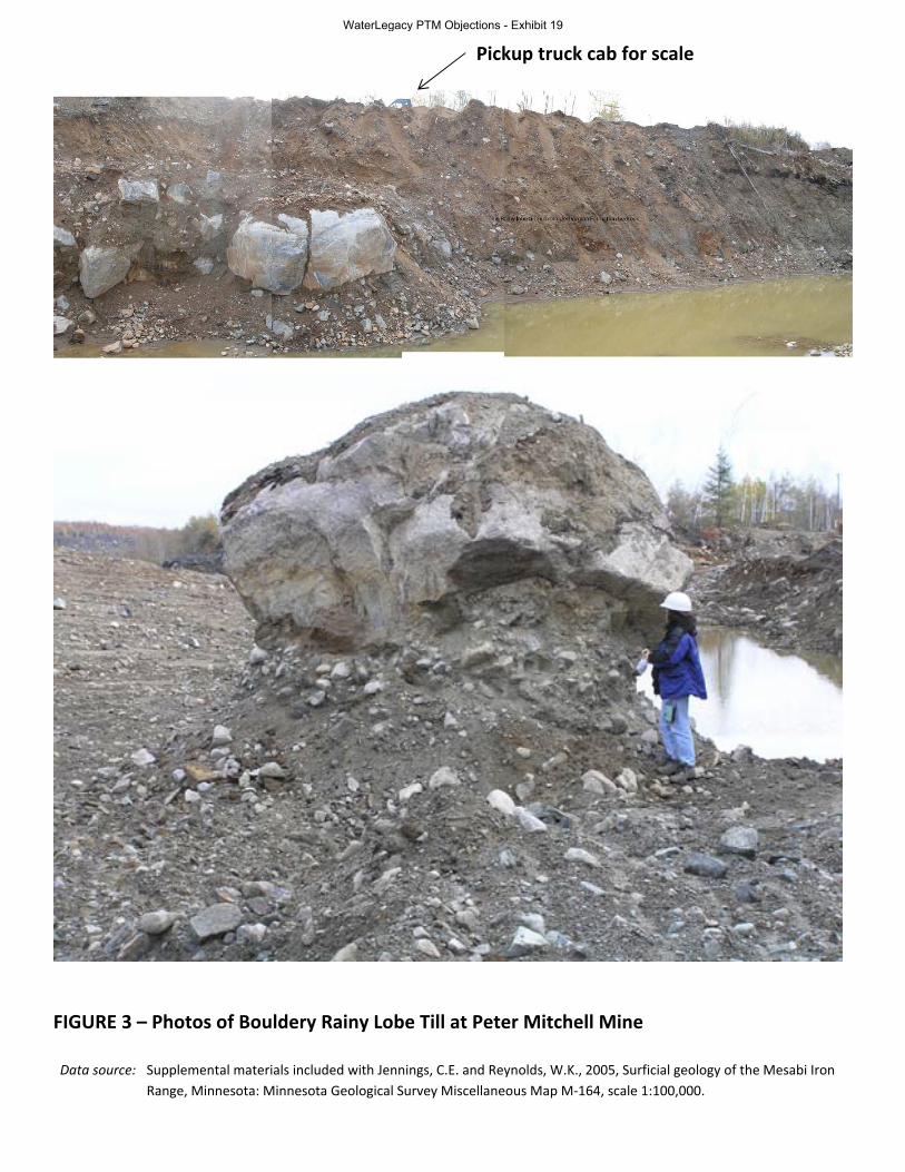
oftentimes bentonite mud is thickened and left in the trench providing the “impermeable” slurry wall. One of the most important aspects of constructing a slurry wall that effectively blocks the flow of groundwater is the nature of the geologic materials into which the slurry wall will terminate. In the Denver area, slurry walls are commonly constructed during the process of mining gravel. Upon cessation of mining the depleted gravel pits are reclaimed for use as surface water reservoirs. The success of slurry walls constructed in this geologic setting relies on the presence of favorable geologic materials into which the slurry wall can be “keyed”. The successful application of slurry wall technology used in the Denver area results from the presence of Cretaceous black shale called the Pierre Shale at the base of the sand and gravel deposit. Pierre Shale is quite impermeable yet rather easily excavated using a clam-shell type bucket from the surface. The geologic situation at the Tailings Basin is not favorable for the typical slurry wall construction technique of keying the slurry wall into bedrock because the bedrock present at the Tailings Basin is granite. This type of rock cannot be easily excavated from the surface using typical slurry wall construction techniques. It is difficult to imagine how construction of an effective slurry wall could be accomplished in this geologic setting without completely dewatering the perimeter of the Tailings Basin, followed by the blasting of a trench into the Giants Range Granite that would serve as the “key” into which the slurry wall the slurry wall would be sealed. Further complicating construction of any type of seepage containment system at the Tailings Basin would be the presence of a very boulder-rich glacial till (Figure 3). In fact the boulder-rich characteristics of this particular Rainy lobe till are so obvious that researchers from the U.S. Geological Survey named it “the bouldery till” (Winter, 1971; Winter et al, 1973). The high percentage of boulders present in this till caused numerous problems in penetrating certain zones during field tests carried out at the Tailings Basin (Pint and Dehler, 2008; PolyMet, 2013n) and at the Mine Site (Barr, 2006b). One additional challenge posed by the presence of boulder-rich till in the construction of a slurry wall around certain portions of the Tailings Basin would be the inability to determine whether slurry wall excavation has actually encountered bedrock or possibly just a very large boulder in the till (Figure 3). Barr’s (2007g) report to PolyMet on the construction of seepage capture systems at the Tailings Basin recognizes that slurry walls are not suitable if boulders or cobbles are present. The details of how an effective slurry wall system could be constructed at the Tailings Basin - one that takes into account actual field geologic conditions - seems to be missing from the SDEIS and supporting documents. Barr Engineering has reportedly designed a seepage collection system for the Tailings Basin with sufficient detail for Ames Construction to have prepared a bid to construct the seepage collection system (Desautels and Zurowski, 2012). These construction plans contain important details that are necessary to understand the assumed effectiveness of the seepage collection system and to predict impacts on groundwater quality should the slurry wall not function as predicted. These critical plans should be made available for review as part of the environmental review process. The subject of contaminant transport from the Tailings Basin seems not to take into account surface drainage conditions and the resulting near-surface groundwater flow conditions that existed prior to the construction of the LTVSMC tailings basin. The quote above from pages 5-68 to 69 in the
WaterLegacy PTM Objections Exhibit 19
Technical Memo to WaterLegacy: Review of NorthMet Mining Project SDEIS (J.D. Lehr, March 12, 2014) Page 19
SDEIS fails to consider groundwater flow emanating from the south side of the Tailings Basin (SDEIS, p. 5-89) and is not supported by PolyMet’s consultant reports.
“At the southern end of the Tailings Basin there is some ground water flow to the south from Cell 1E forming the headwaters of Second Creek. As the Tailings Basin was built up over time, a groundwater mound formed beneath the basin due to seepage from the basin altering local flow directions and rates. Active seeps have been identified on the south, west and north sides of the Tailings Basin….groundwater likely flows out from beneath the tailings basin into the surrounding glacial deposits to the south, west and north of the basin.” (Barr, 2009f, P. 3)
Examination of U.S. Geological Survey topographic maps from 1949 that predate tailings basin construction show that about one-third of the area currently beneath the southern portion the Tailings Basin or about 1,000 acres, historically drained to the south and formed the headwaters of Second Creek (Figure 4, Figure 5). The remainder of the area currently beneath the Tailings Basin, or about 1,900 acres, historically drained to the northwest and north. The recognition that 1,000 acres of the sub-tailings basin watershed originally drained to the south into Second Creek is in disagreement with the SDEIS’ characterization of this being a “small area” (SDEIS, p. 5-89). Groundwater seeps that flow naturally into the headwaters of Second Creek are known to exist on the south side of the Tailings Basin (SDEIS, p. 5-89; PolyMet, 2012a) where the design of any new proposed engineered seepage capture system seems to ignore groundwater flow south out of the Tailings Basin and into alluvial sediments that make up the now highly altered upper reaches of Second Creek. An existing capture and pump back system is apparently in place at this location (SDEIS, p. 5-89). Its ongoing performance should be addressed in this section of the SDEIS as well as how proposed changes to the Tailings Basin hydrology over the 20-year mine life will affect these seeps and the existing seepage collection system. The SDEIS also does not acknowledge existing seepage along the east side of the Tailings Basin (Seep 31 shown on Figure 6 in Barr, 2007g) nor discuss how the historic streams flowing from Spring Mine Lake may affect groundwater flow to the east from beneath the Tailings Basin. The placement of NorthMet tailings into Cells 1E and 2E is proposed to raise the elevation of these cells to the same elevation as the western cell of the tailings basin by the time of closure or to an elevation of 1,735 feet above sea level (SDEIS, p. 3-102). This higher land surface will result in an elevated water table within the eastern cells of the tailings basin just as the western cell has. The water table will remain high for possibly hundreds of years or longer due to pump back of seepage captured from the perimeter of the Tailings Basin. It is conceptually possible that this increase in head within the Tailings Basin will eventually result a reversal of groundwater flow within the alluvial sediments present in the valley of the stream flowing west from Spring Mine Lake. According to high resolution LiDAR topographic data the current elevation of the water plane within Cell 1E is about 1,650 feet in elevation and the elevation of Spring Mine Lake is 1676 feet in elevation, thereby preserving the natural relationship where Spring Mine Lake is higher than the tailings basin area, so that groundwater in valley of the creek flowing westward from Spring Mine Lake still likely flows toward the Tailings Basin. However, at closure Cell 1E will rise 59 feet above the surface of Spring Mine Lake reversing this topographic relationship. The potential for seepage from the Tailings Basin
WaterLegacy PTM Objections Exhibit 19
Technical Memo to WaterLegacy: Review of NorthMet Mining Project SDEIS (J.D. Lehr, March 12, 2014) Page 20
towards the east due to these current and forecast conditions and the potential need for a seepage collection system on the east side of the Tailings Basin seems to have been overlooked in the SDEIS. Of particular interest to the subject of contaminant transport from the Tailings Basin is the amount of nickel that is unrecoverable during processing and will end up in the Tailings Basin. Most of the nickel in the NorthMet deposit occurs in sulfide minerals, most notably pentlandite (PolyMet, 2007b). Most of the nickel occurring in sulfide minerals will be recovered during processing, but according to PolyMet’s own report (2007b) there is a “25 to 35% loss of nickel to silicates.” In other words, of the total amount of nickel that exists in the NorthMet deposit a maximum of only 65 to 75% is expected to be recovered and 25 to 35% will end up in the Tailings Basin bound up in silicate minerals. Nickel occurs in silicate minerals where nickel ions replace iron and magnesium ions within the crystal lattice of minerals such as olivine. This nickel cannot be economically recovered from the olivine so the nickel-bearing olivine mineral grains end up deposited in the Tailings Basin. What is particularly notable about the situation of nickel in the tailings is that elsewhere the SDEIS presents evidence to suggest that low sulfur rock (< 0.12% S) has little risk for acid generation due to the buffering capacity of calcium that is released from silicate minerals such as pyroxene (diopside) and calcic plagioclase feldspar.
“there are essentially no acid-neutralizing carbonate minerals in NorthMet waste rock, but silicate minerals—including plagioclase feldspar ([Na,Ca][Si,Al]4O8), olivine ([Mg,Fe]2SiO4), and pyroxenes (e.g., diopside, MgCaSi2O6)—neutralize some acid, which would delay acid onset in some rock and would prevent entirely the onset of acidic conditions in rock with less than 0.12 percent sulfur” (SDEIS, p. 5-51)
Weathering results in the release of calcium ions from the lattice of these minerals. The same weathering process that liberates calcium to buffer acid will also cause nickel to be released from the lattice of olivine. The presence of large amounts of nickel in silicate mineral tailings exacerbates potential water quality issues due to surface area of olivine tailings, which will be sized as fine sand or silt. It is well-known that mobilization of elevated concentrations of nickel does not require acid conditions (SRK, 2007b), and that under commonly-occurring conditions, olivine generally weathers before pyroxene and plagioclase (Goldich, 1938). Waters flowing through the tailings piles will be oxygen-rich due to the continual pump-back of captured seepage, further contributing to accelerated release of nickel from olivine. This situation where large amounts of nickel are weathering from silicate minerals within the Tailings Basin coupled with the likelihood that significant volumes of seepage will escape capture from around the Tailings Basin is likely to lead to excessive levels of nickel migrating off-site. The SDEIS should explicitly analyze the “loss of nickel to silicate” issue, in light of the hydrogeology of the Tailings Basin. 3.0 SURFICIAL GEOLOGY At both the Mine Site and the Tailings Basin, a variety of distinct Precambrian bedrock units are overlain by a discontinuous variable thickness of sediments deposited in association with the advance and retreat of multiple continental glaciers. In many places at both the Mine Site and
WaterLegacy PTM Objections Exhibit 19
Technical Memo to WaterLegacy: Review of NorthMet Mining Project SDEIS (J.D. Lehr, March 12, 2014) Page 21
Tailings Basin these glacial sediments are in turn overlain by post-glacial peat accumulations. The bedrock surface topography is highly irregular with outcrops common in many areas at both sites. A scientifically sound understanding of the three dimensional distribution of the variety of surficial sediments present at the Mine Site and Tailings Basin and an accurate characterization of their range of physiochemical properties must be achieved for a number of important reasons including the following: 1) Surficial sediments represent the overburden that must be stripped and stockpiled, and possibly used in construction, in a way that minimizes risks to water quality and human health. The physiochemical properties of these materials must be well understood in order to effectively manage these risks; 2) Surficial sediments will form the foundations of the various stockpiles proposed to be built and make up the foundation of the current LTVSMC tailings basin. They provide either barriers or pathways for groundwater leaching through stockpiles and tailings impoundments; and 3) Surficial sediments are the container for near-surface groundwater and they provide the medium for the interaction of process water, surface water in wetlands and streams and groundwater in surficial materials and in bedrock. Generalizations based on assumptions are made throughout the SDEIS to infer the physiochemical properties and distribution of surficial sediments. These assumptions are then used to infer hydrologic conditions that are in turn used as inputs and in calibration of predictive models. In general the approach taken towards understanding the surficial geology of the Mine Site and Tailings Basin in the SDEIS is very simplistic. 3.1 Surficial Geology – Mine Site The discussion of the surficial geology of the Mine Site begins with the following statement.
“The surface material that would be encountered by the NorthMet Project Proposed Action mining include a relatively thin (0 to ~59 ft thick) surficial layer of unconsolidated glacial till.” (SDEIS, p. 4-43)
This is one of several instances within the SDEIS where the entire assemblage of surficial sediments is described using a term more correctly reserved for specific types of surficial sediments. The word “till” here is used in sort of a slang fashion to refer to all of the surficial materials that occur at the Mine Site, including well-sorted sediments which, by definition are not “till.” In addition, 60 feet of surficial sediment is not “thin;” there can be a variety of different types of sediments with different hydrologic properties present within a surficial section this thick. Another example of overgeneralization of Mine Site surficial geology:
“Water table elevations measured by PolyMet in Mine Site bedrock boreholes indicate that the hydraulic gradient is similar to that of the overlying alluvium (sloping down to the south and southeast across the Mine Site), consistent with a hydraulic connection between the alluvium and bedrock units (PolyMet 2013i).” (SDEIS, p. 4-46)
A few pages above, the term “till” was used as a general term, now in this paragraph the term “alluvium” seems to be used as a replacement term for all surficial sediments. On page 4-149 the entire package of surficial sediments is referred to as “soil”. This is more than semantics; it leads to
WaterLegacy PTM Objections Exhibit 19
Technical Memo to WaterLegacy: Review of NorthMet Mining Project SDEIS (J.D. Lehr, March 12, 2014) Page 22
confusion as to exactly which surficial sediments are being referenced: the entire surficial sediment section or only till units or only alluvium units or only the post-glacial soil that exists at the land surface? This usage promotes a simplistic understanding of surficial geology, which in turn is converted into overly simple and inaccurate inputs to predictive models. In addition to till, other surficial sediments present at the Mine Site include lacustrine sediments and outwash sand and gravel (PolyMet, 2007b; Barr, 2006b). The rotasonic drilling program reported “a highly compacted gray clay unit with numerous pebbles was encountered just above bedrock in several borings” (Barr, 2006b). This unit likely represents one or more individual older till units that are known to exist in the area of the eastern Mesabi Range (Winter, 1971; Winter et al, 1973; Lehr and Hobbs, 1992). These various surficial sediments have widely ranging textures and different weathering histories and therefore potentially widely ranging hydrologic properties. Rather than describe Mine Site geology, the SDEIS provides regional generalizations.
“This surficial till is relatively young (~14,000 to 60,000 years old), and has been described at a regional scale as unsorted sandy loam mixture with pebbles, cobbles, and boulders (Jennings and Reynolds 2005).” (SDEIS, p. 4-43)
This statement doesn’t accurately describe Mine Site surficial sediments. First, there is more than one till unit at the Mine Site (PolyMet, 2013i; Barr, 2006b). Drilling logs in these reports provide numerous examples where multiple tills were encountered during drilling at the Mine Site. In some instances multiple tills are separated by intervals of outwash sand and gravel - some that are greater than 10 feet thick (RS-11 for example in PolyMet, 2013i). The thickness and extent of these outwash zones in the subsurface should have received more attention in the SDEIS; they represent significant pathways for groundwater flow and contaminant transport. The surficial Rainy lobe till maybe about 14,000 years old, but not anywhere near 60,000 years old. Older tills that occur stratigraphically below the surficial Rainy lobe till may be 60,000 years old but could be much older (Lehr, 2000). The patchy older tills that are known to exist along the eastern Mesabi Range (Winter, 1971; Winter et al, 1973; Lehr and Hobbs, 1992) could have been deposited during several different glacial episodes over the past couple of million years, with the patchwork of older tills surviving erosion for that long having been somewhat protected from glacial erosion by the topographic lee created by the crest of the Giants Range (Lehr and Hobbs, 1992; Lehr, 2000). This age distinction isn’t trivial because a till with a 14,000 year weathering history will have been subject to a much shorter period of weathering than a till perhaps millions of years old. The different weathering histories of the various tills result in different physiochemical properties. Further hydrologic significance related to older tills, especially those that are more clay-rich, is that they oftentimes exhibit strong vertical jointing especially compared to tills deposited during the last glacial episode. Tills that have undergone glacial isostatic flexing are fractured just like bedrock. The joints present in older relatively fine-grained till are fractures that have the potential to transmit groundwater just as bedrock fractures do (Golder Associates, 2010), another situation that seems to have been overlooked in the SDEIS.
WaterLegacy PTM Objections Exhibit 19
Technical Memo to WaterLegacy: Review of NorthMet Mining Project SDEIS (J.D. Lehr, March 12, 2014) Page 23
The simplistic conceptual model of surficial geology at the Mine Site has resulted in a very simple and likely flawed plan to mitigate water quality problems that may arise from the presence of sulfur and metals in the overburden.
“Three types of overburden are present at the site: unsaturated overburden, saturated overburden, and peat. Each type of overburden would be managed according to its potential to be reactive (i.e., acid-producing through oxidization of iron sulfides).” (SDEIS, p. 3-44)
Surficial materials at the Mine Site are heterogeneous, so a simplified approach to predict and mitigate acid generation and metal leaching from overburden stockpiles and construction with overburden materials may be ineffective. Overburden at the Mine Site contains a diverse assemblage of glacial sediments that includes multiple tills, lacustrine sediments, and outwash sand and gravel (PolyMet, 2007b) that is overlain in many places by post-glacial peat accumulations. An effective plan to mitigate impacts of contaminated water discharging from overburden stockpiles at the Mine Site requires consideration of the physical properties of these materials. Unsaturated and saturated are not “types of overburden”, but rather these are terms that describe a hydrologic condition of the sediments that comprise the overburden at a particular time. The obvious should be pointed out here and that is that none of the overburden at the Mine Site – glacial sediments or peat - will be saturated by the time it is removed and placed in stockpiles. The water levels in the overburden will have been lowered by pumping (dewatered) to allow for the removal of previously saturated overburden with large-scale excavating equipment. As soon as the overburden material begins to drain during dewatering, the oxidation rate of sulfide minerals will increase and mobility of metals will increase along with the resulting decrease in pH. Whether overburden is saturated or unstaturated may not have a direct bearing on its potential to generate acid or leach metals. For example, unsaturated sand and gravel would likely contain fewer unweathered sulfide mineral grains and more sulfide-mineral weathering by-products due to availability of greater amounts of oxygen in that porous sediment than might unsaturated clayey lacustrine sediments or many varieties of till. The assumption that the boundary between acid-generating overburden and non-acid generating overburden at NorthMet coincides precisely with the water table directly contradicts an entire body of geologic literature known as “drift prospecting” or “drift exploration” and is therefore most likely flawed. The vast drift prospecting literature has received extensive peer review, and the SDEIS has not. Drift prospecting techniques have long been used with great success across the Precambrian shield areas of North America and Fennoscandia to target ore deposits in the bedrock (see papers included in DiLabio and Coker, 1989, and McClenaghan et al, 2001 for example). In addition to the papers presented in the two previously cited references that represent international research on the subject of drift prospecting, the Minnesota DNR Division of Lands and Minerals has an extensive catalog of “drift prospecting” studies that they have carried out over the years to promote mineral exploration. A commonly used technique in drift prospecting studies involves collecting a set of samples from glacial till and analyzing them for ore minerals, ore tracer minerals and chemical signatures that are indicative of ore deposits. The ore minerals and ore tracer minerals often occur in the sand size
WaterLegacy PTM Objections Exhibit 19
Technical Memo to WaterLegacy: Review of NorthMet Mining Project SDEIS (J.D. Lehr, March 12, 2014) Page 24
fraction of the till while the chemical signatures that result from weathering of ore minerals are usually found in the silt and clay fraction (minus 63 micron fraction). When the results of this type of survey are mapped and scrutinized using a sound understanding of glacial and bedrock geology, trends sometimes become apparent and the location of ore deposits are revealed by what are called dispersal trains. One salient characteristic of mineral or chemical dispersal trains is that they often display a very predictable decrease in the concentration of ore deposit indicators in the down-ice direction from the ore deposit. In other words the concentration of ore deposit indicators within till in the vicinity of mineral deposits is most often greatest on top of the ore deposit and immediately down-ice and then decreases systematically in the direction of glacier flow. Since many common metallic ore minerals are sulfide minerals, they are susceptible to weathering in the oxidized upper portion of the glacial sediments that overlie bedrock. Till sampling techniques employed in drift prospecting studies commonly involve hand-digging holes in areas where till occurs at the surface, but only to a depth where the till is at least relatively unoxidized; not to the point of reaching saturated material. This objective is often achieved by digging a hole only about 3 feet deep in many areas on the Canadian Shield. Sometimes elevated levels of metals occur within the modern soil at the land surface near ore deposits. Anomalous concentrations of Cu, Ni, Co, Ag, Pt, Pd and Au are documented to occur in the fine fraction of B-horizon soils in association with basal Duluth Complex ore deposits in the vicinity of NorthMet (Alminas, 1975; Alminas and Dahlberg, 1994). This suite of ore metals often occurs in association with elevated levels of As, Sb, Zn, Pb and Hg also liberated from sulfide minerals by weathering. If the assumptions in the SDEIS about the benign acid generating potential and low metal content of unsaturated overburden were true, then the till sampling techniques used in drift prospecting studies would not work unless till samples were collected from saturated material. Based on countless peer-reviewed studies, this is not true. Any NorthMet geochemical test results from unsaturated overburden presented in support of the overburden management plan in the SDEIS would be very sensitive to the texture of the material chosen for testing and its age and yet neither the SDEIS or PolyMet (2013l) report what types or textures of unstaturated overburden were subjected to geochemical analyses. As discussed previously as well as in the literature supporting the SDEIS, the assemblage of surficial sediments (overburden) at the NorthMet site is heterogeneous, ranging from clay and till to sand and gravel. Sediments present within in the Mine Site overburden have widely ranging physical and hydrologic properties that will govern the rate of sulfide mineral weathering and mobilization of metals. The spatial variability in texture displayed in sediments and sedimentary rocks is referred to as sedimentary facies. The various facies or subunits of surficial Rainy lobe till mapped within the area of the eastern Mesabi Range are texturally quite variable, particularly at former ice margins where melt water played a larger role in deposition (Lehr, 2000; Jennings and Reynolds, 2005). The ice-marginal facies of Rainy lobe till include more numerous layers of permeable sand and gravel and will oxidize more rapidly than more compact subglacial Rainy lobe till. Finally, some of the older sediments that are known to exist within the project area are described as “very dense clay” (Barr, 2006b; PolyMet, 2013i). Fine-grained sediments may be very effective at minimizing the oxidation of sulfide minerals even within the unsaturated zone due to their density and high clay content.
WaterLegacy PTM Objections Exhibit 19
Technical Memo to WaterLegacy: Review of NorthMet Mining Project SDEIS (J.D. Lehr, March 12, 2014) Page 25
The subject of whether unsaturated (but unoxidized) overburden has the potential to create acid or leach metals is an important one. The SDEIS assumes that all unstaturated overburden is benign.
“Unsaturated overburden is the material that has been above the natural water table and exposed to air long enough for chemical reactions to have taken place.” (SDEIS, p. 3-44)
This statement is unsupported and misleading. Chemical reactions have taken place in the overburden, especially in the unsaturated portion (vadose zone), but also in the saturated zone, just at a slower rate. What is implied with this statement is that a long enough period of time has elapsed since the deposition of overburden sediments for vadose zone weathering to have to have completely converted sulfide minerals into products that will not generate acid or leach metals. This statement neither takes into account drift prospecting literature which has documented metals in fine fractions of till collected from the vadose zone even when the sulfide minerals themselves have been completely weathered; nor the fluctuation of groundwater levels between the time the oldest overburden sediments were deposited and the present time. Local field evidence supports the presence of incompletely leached and weathered older tills. I have personally collected Paleozoic carbonate fossils from an oxidized, unsaturated till that occurs immediately below the surficial Rainy lobe till at the Dunka Pit. The presence of pristine carbonate fossil material within the unsaturated oxidized zone of older tills of the eastern end of the Mesabi Range is an indication of very incomplete leaching of certain unsaturated yet oxidized surficial sediments. Unless and until data or references are provided, SDEIS claims that unsaturated overburden at NorthMet does not contain acid generating or metal leaching materials are unreliable.
“The overlying surficial sediments at the Mine Site are poorly sorted and range from very dense clay to well-sorted sand with boulders and cobbles (Barr 2006b; Golder Associates 2007). Hydraulic testing of the surficial sediments indicates that these sediments may contain layers of relatively low hydraulic conductivity (e.g., comparable to the Duluth Complex).” (SDEIS, p. 4-45)
As discussed previously, detailed knowledge of the three-dimensional spatial relationships amongst the various surficial sediments allows for accurate prediction of the hydrologic properties of the surficial sedimentary package and its relationship to the bedrock hydrologic system. In reports such as the SDEIS where geology plays such an important role, subsurface data such as drilling and trenching results are customarily portrayed using geologic cross-sections and maps that show the spatial relationships that exist amongst the various sedimentary units and their relationship to the bedrock surface. Geologic cross-sections showing the spatial distribution of these “layers of relatively low hydraulic conductivity” and the relationship of these sediments to the irregular bedrock surface across the entire NorthMet project area are missing from the SDEIS.
“Tests using wells that penetrate through the surficial zone, however, found much higher average hydraulic conductivity, with values similar to the Biwabik Formation aquifer (see Table 4.2.2-5). (SDEIS, p. 4-45)
WaterLegacy PTM Objections Exhibit 19
Technical Memo to WaterLegacy: Review of NorthMet Mining Project SDEIS (J.D. Lehr, March 12, 2014) Page 26
The above statement from the SDEIS correctly acknowledges the heterogeneity of hydraulic conductivity values for surficial sediments present at the Mine Site. Unfortunately, this range of variability is not retained in model inputs; instead average hydraulic conductivities seem to be used. The importance of understanding the three-dimensional distribution of surficial sediments to accurately predict ground water flow and chemistry cannot be understated. Some of the zones encountered during drilling with “much higher average hydraulic conductivity” likely represent eskers and related outwash sediments that are known to exist at the Mine Site and at the Tailings Basin Site. Figure 6 shows the distribution of surficial sediments and glacial landforms in the vicinity of the Mine Site prepared by separate mappers (Jennings and Reynolds, 2005; Lehr and Hobbs, 1992; Lehr, unpublished mapping, 2010-2014). Most of the Mine Site is underlain by three different types of till (Jennings and Reynolds, 2005). Of the three till units mapped at the Mine Site two occur mainly in the eastern portions of the Mine Site in close association with bedrock outcrops (Figure 6). These two eastern till units (Rainy Lobe Till and Water Eroded Rainy Lobe Till) contain fewer sand and gravel lenses relative to the till unit mapped over the western one third of the Mine Site (Jennings and Reynolds, 2005). The map unit Re-sedimented Rainy Lobe Till and Sorted Sediment shown over the western one third of the Mine Site is a hybrid map unit consisting of both re-sedimented till and sorted sand and gravel (Jennings and Reynolds, 2005). The occurrence and distribution of sand and gravel layers reported to be present within this till mapping unit will have significant bearing on the movement of groundwater through the surficial sedimentary package. Perhaps of most significance, this hybrid till and sand and gravel mapping unit with higher hydraulic conductivity appears to underlie much of the area where the unlined Category 1 waste rock stockpile is proposed to be built (Figure 6). Bedrock outcrops are more common in the eastern two thirds of the mine site (Figure 6) occurring amongst areas of probably rather thin till. Of note is the entire lack of bedrock outcrops mapped within much of the area underlain by the hybrid till/sand and gravel unit. This observation indicates that the overall thickness of glacial sediments is greater and therefore likely more heterogeneous beneath the eastern one third of the Mine Site. In other words, sand and gravel layers will be more commonly interbedded with till in this area thereby creating high hydraulic conductivity pathways for contaminated groundwater. There are the numerous esker segments visible on the LiDAR topographic imagery for the Mine Site (Figure 6). Eskers can be hydrologically significant because they are linear, ridge-like landforms composed of sand and gravel and for that reason could provide high hydraulic conductivity pathways for contaminated groundwater flow. Note that several eskers are mapped between the boundary of the Mine Site and the Partridge River both north and south of the Mine Site. Also note the esker segments mapped in the vicinity of the Category 1 waste rock stockpile. These eskers were not shown on Jennings and Reynolds (2005) map because detailed topographic data were not available to the Minnesota Geological Survey at that time, but detailed (2-foot contour) topographic mapping of the Mine Site has been available to PolyMet and its consultants since 1999 (PolyMet, 2007b). These eskers may represent conduits for groundwater to flow, yet their presence and significance is not acknowledged within the SDEIS.
WaterLegacy PTM Objections Exhibit 19
Technical Memo to WaterLegacy: Review of NorthMet Mining Project SDEIS (J.D. Lehr, March 12, 2014) Page 27
Both Jennings and Reynolds (2005) and Lehr (Lehr and Hobbs, 1992; Lehr unpublished mapping 2010-2014) have mapped a Rainy lobe ice margin transecting the southwest corner of the Mine Site. This is significant to the hydrogeology of the Mine Site because the glacial ice-marginal depositional environment contains copious amounts of melt water that mobilizes unsorted glacial debris to produce a heterogeneous assemblage of interlayered till and sorted sand and gravel layers. In many places along the eastern Mesabi Range including portions of the NorthMet project area the Rainy lobe was fronted by a glacial lake (Jennings and Reynolds, 2005; Lehr and Hobbs, 1992). Ice-marginal sedimentation by glacial melt water and gravity into the ice-marginal pro-glacial lake environment resulted in large amounts of sand and gravel deposited directly where the ice margin terminated in the lake. Linear belts of sand and gravel commonly marking the former positions of the Rainy lobe ice margin where it retreated through northeastern Minnesota and northwestern Ontario (Sharpe and Cowan, 1990; Lehr, 2000; Lehr and Hobbs, 1992) are an indication of the widespread conditions that promoted ice-marginal sand and gravel deposition across portions of the NorthMet site.
“Shallow borings and test trenches at the Mine Site encountered bedrock at depths ranging from 3.5 to 17 ft below ground surface (bgs). The site exploration drilling database, drilling logs, and electrical resistivity data were used to develop an estimated depth-to-bedrock isopach map (Golder Associates 2007).” (SDEIS, p. 4-45)
A figure showing this isopach map inserted at this point in the SDEIS would be very helpful in envisioning how the surficial sediment type and thickness varies across the Mine Site. But this map neither appears in the SDEIS or among cited reference documents. The Table of Contents for Golder Associates (2007) lists the isopach map, but the file does not appear in the MDNR DVD set and was not available for review. A detailed bedrock topography map would also be useful at several places in the SDEIS to illustrate where features such as troughs and bedrock valleys are located on the bedrock surface and to assess pathways that may transmit contaminated groundwater at the interface of the overburden and bedrock.
“Although the isopach contouring indicates local depressions in the bedrock where estimated surficial cover thickness reaches 50 ft, no major areas of highly permeable outwash sands and gravel have been reported that might serve as groundwater conduits through the unconsolidated material.” (SDEIS, p. 4-46)
Whatever “major areas” means, the presence of highly permeable outwash within the overburden is important. Knowing dimensions of sand and gravel outwash layers within the overburden and their orientation would help predict where groundwater conduits and seeps will be located within the overburden. It appears that no surficial geologic maps for the project areas were prepared specifically for the environmental review process. This is a serious deficiency in a geologic data set that underpins so much of the predictive modeling that is presented in the SDEIS. The SDEIS, in addition, ignores most of the detail in published surficial geologic maps for the area. With respect to geology, the result is a data-poor environmental review process. The supplemental photographs included in Jennings and Reynolds (2005) provide specific examples from eastern Mesabi Range mines where geologic materials occur within the overburden that could act as groundwater conduits and seeps. Figure 7 shows two photos from
WaterLegacy PTM Objections Exhibit 19
Technical Memo to WaterLegacy: Review of NorthMet Mining Project SDEIS (J.D. Lehr, March 12, 2014) Page 28
the Embarrass mine 7 miles west of NorthMet and one photo from the Dunka pit about 7 miles northeast. The two photos from the Embarrass mine show cross-sections through crudely tubular-shaped gravel bodies that are surrounded by finer grained sediments. The photo from Dunka pit shows what looks more like a tabular layer of gravel sandwiched between two separate tills (Figure 7). These are commonly occurring geologic conditions. Similar conditions are likely to exist at the NorthMet site, and would provide high hydraulic conductivity pathways for groundwater and contaminants to flow at rates much higher than the surrounding sediments. The above statement from page 4-46 of the SDEIS about a lack of outwash sand and gravel at the Mine Site is in disagreement with several drilling logs included in the supplementary materials (PolyMet, 2013i). Each of the drill holes listed in the table below encountered what was described as either outwash or clean sand or gravel or some combination thereof.
The spatial distribution of permeable outwash layers and their hydrologic significance must be considered for accurate modeling of groundwater flow, but this has not happened in the SDEIS. PolyMet has carried out extensive geologic field investigations at the NorthMet Mine Site and they do report outwash to be present within the overburden (PolyMet, 2007b; 2013i). For example drill hole RS-11 was drilled to a depth of 33 feet using the highly accurate rotasonic drilling method. The drilling log for RS-11 shows an 11-foot-thick interval of sand and gravel outwash sandwiched between two separate till units (PolyMet, 2013i). Two samples were collected from the core recovered from this outwash interval and were submitted for grain size analyses resulting in gravel-sand-fines ratios of 35-59-6 (17 to 25 foot interval) and 23-67-10 (25 to 28 foot interval) (PolyMet, 2013i). Even where field data was available, it appears that it has been misused in preparing SDEIS models. In a section of PolyMet, 2013i entitled “Updates to Mine Site MODFLOW Model Calibration and
WaterLegacy PTM Objections Exhibit 19
Technical Memo to WaterLegacy: Review of NorthMet Mining Project SDEIS (J.D. Lehr, March 12, 2014) Page 29
Predictive Simulations” there a discussion of hydraulic conductivity values for surficial sediments used in calibrating the MODFLOW model is presented. It is explained that aquifer testing data from 9 monitoring wells screened in the unconsolidated deposits resulted in estimates of hydraulic conductivity values ranging from 0.12 to 30 ft/day (PolyMet, 2013i). The paragraph goes on to describe how grain-size distribution data resulting from samples collected from 19 rotasonic borings were used to estimate hydraulic conductivity according to a method described as “Barr, 2001”. Hydraulic conductivity values were averaged for borings with multiple samples. “Two grain-size samples were excluded from the average hydraulic conductivity calculation at one location (RS-11) due to anomalously high values associated with high gravel content” (PolyMet, 2013i). This is not an appropriate use of data. Intervals with “high gravel content” such as this represent actual field conditions - albeit extreme- that are documented to exist at the Mine Site. They should not be excluded from the groundwater model. Even after excluding these extreme values, the estimated hydraulic conductivity of surficial sediments in this report ranged from 2.2 ft/day to 167 ft/day (PolyMet. 2013i). Stark (1977) reported laboratory derived hydraulic conductivity values for surficial sediments just to the northeast of NorthMet that ranged from 0.4 to 362 feet per day. These hydraulic conductivity values for surficial materials based on laboratory methods seem to be in conflict with hydraulic conductivity values presented in Table 4.2.2-5. In this table, laboratory-derived hydraulic conductivity values for reported “silty sand” are shown as ranging from 0.00043 ft/day to 0.0081 ft/day. The difference between laboratory-derived hydraulic conductivity values of up to 167 ft/day reported in PolyMet, 2013 or even higher in Stark (1977) should be reconciled with the results from a silty sand presented in Table 4.2.2-5 in the SDEIS. It is also important to note that gravel percentages of 23 and 35 percent are not at all extreme when compared to the gravel content of many other varieties of surficial sediments known to exist in the immediate vicinity of the NorthMet Mine Site and Tailings Basin. Surficial sediments with gravel contents of greater than 60 percent are known to be present at the Mine Site (PolyMet, 2013i, Log of Boring RS-5A for example) and sediments with gravel contents ranging from 50 to greater than 80 percent are mapped in close proximity to NorthMet (Lehr, 2000, Appendix A). While certain of these laboratory derived hydraulic conductivity values mentioned above may seem high – in the 100’s – Siegel and Ericson (1980) reported hydraulic conductivities based on aquifer testing of surficial sand and gravel within the copper-nickel study area to range from 10 to 3,500 feet per day and Rainy lobe till hydraulic conductivities to range from 0.01 to 30 feet per day. Not only are the physical properties of surficial sediment important to groundwater flow, so are their spatial arrangement.
“Figure 5.2.2-4 shows surficial groundwater flowpaths with the potential to transport mine-affected groundwater from identified source areas to designated evaluation locations.” (SDEIS, p. 5-33)
Figure 5.2.2-4 is a map showing the surficial groundwater flow paths at the Mine Site. This map does not show any surficial groundwater flow paths from the Mine Site to the north toward 100
WaterLegacy PTM Objections Exhibit 19
Technical Memo to WaterLegacy: Review of NorthMet Mining Project SDEIS (J.D. Lehr, March 12, 2014) Page 30
Mile Swamp and Yelp Creek or to the northeast. This is unusual. It is stated elsewhere in the SDEIS, as well as being common knowledge that the elevations of groundwater surfaces in surficial sediments under unconfined conditions usually mimic surface topography.
“the water table is generally a subdued replica of the land surface, with groundwater divides in the Mine Site expected to roughly coincide with surface water divides” (SDEIS, p. 4-149).
A few pages later in the SDEIS it is stated:
“there is a surface drainage divide oriented generally from southwest to northeast near the northern border of the Mine Site. The majority of the Mine Site, approximately 80 percent, drains south to the Partridge River through extensive wetland complexes. The remaining 20 percent of the Mine Site drains north to the One Hundred Mile Swamp and the Partridge River or northeast to the Partridge River” (SDEIS 4-151).
It follows from these statements, in addition to well-understood geological concepts, that 20 percent of the surficial groundwater flow paths from the Mine Site should be to the north and northeast. This seems to have been ignored and should be corrected in the SDEIS groundwater modeling or it should be better explained why near-surface groundwater flow does not follow surface topography at the Mine Site. It should also be explained why Figure 2-3 in Polymet 2012s shows flowpaths from the Mine Site north to 100 Mile Swamp and Yelp Creek. This figure shows travel times of 1-5 years and 5-10 years along these flowpaths, not the travel times of thousands of years stated in the SDEIS (p. 5-33). 3.2 Surficial Geology – Tailings Basin The level of detail presented in sections describing the surficial geology of the Tailings Basin area is minimal, not well referenced and is not based on site-specific geologic studies. The following statement made by Barr Engineering sums up their contribution to the understanding of the surficial geology of the Tailings Basin Area in support of the SDEIS. “Site specific geologic studies of the glacial deposits have not been conducted” (Barr 2009f). For this reason, the SDEIS must rely upon the published literature and anecdote to characterize Tailings Basin surficial geology. One published reference the SDEIS relies heavily upon to characterize the surficial geology is Jennings and Reynolds, 2005. In fact the SDEIS’ discussion of surficial geology at the Tailings Basin leads off with the following sentence.
“Jennings and Reynolds (2005) mapped the surficial deposits around and beneath the Tailings Basin as Rainy Lobe Till, which functions as the surficial aquifer and is generally a boulder-rich till with high clay content.” (SDEIS, p. 4-95)
A continuous layer of till with “high clay content” would be desirable beneath an unlined tailings impoundment. It would serve to direct groundwater to predicable locations where it could then be captured and treated. Unfortunately the quote above is entirely incorrect; the surficial Rainy lobe till in the vicinity of the Tailings Basin does not have high clay content. This claim that the Rainy lobe till has a high clay content is a direct contradiction to what is stated in multiple places the cited reference. Jennings and Reynolds (2005) clearly report the surficial Rainy lobe till they mapped in
WaterLegacy PTM Objections Exhibit 19
Technical Memo to WaterLegacy: Review of NorthMet Mining Project SDEIS (J.D. Lehr, March 12, 2014) Page 31
the vicinity of the proposed NorthMet project to be “clay-poor”. They report Rainy lobe till matrix textures to range from 48 to 87% sand, 9 to 40% silt and 0 to 13% clay and that the matrix contains “generally much less than 10% clay” (Jennings and Reynolds, 2005) - this is a sandy till, not a clayey till. The statement above further misleads the reader by not fully describing the variety of till units that Jennings and Reynolds (2005) have mapped in the vicinity of the Tailings Basin. Figure 8 shows the distribution of three different till map units in the vicinity of the Tailings Basin. The Rainy Lobe Till and Water Eroded Rainy Lobe Till map units will contain fewer layers of sand and gravel than will the third till unit mapped in the vicinity of the Tailings Basin – Re-sedimented Rainy Lobe Till and Sorted Sediment (Jennings and Reynolds, 2005). The later unit is a hybrid mapping unit consisting of re-sedimented Rainy lobe till and layers of sorted sand and gravel. This detail about till units demonstrates that the cited reference supports the exact opposite of the claims made in the SDEIS for the presence of “clay-rich” till at the Tailings Basin. The sand and gravel layers within the Re-sedimented Rainy Lobe Till and Sorted Sediment unit will provide significant pathways for groundwater flow and contaminant transport at the Tailings Basin as well as at the Mine Site. The following sentence seems to downplay the significance of outwash at the Tailings Basin.
“The area farther northwest of the Tailings Basin is believed to be one of the few areas in the region with significant quantities of outwash (sand and gravel) and thicknesses ranging from 0 ft to greater than 150 ft (Olcott and Siegel 1979) (see Figure 4.2.2-12).” (SDEIS, p. 4-95)
The mention here of significant quantities of outwash sand and gravel occurring some unspecified distance “farther northwest of the Tailings Basin” is irrelevant to the geology of the Tailings Basin site. The SDEIS does not cite references that may allow for a more accurate characterization of the surficial geology of the Tailings Basin site. A large-scale existing surficial geologic map (Lehr, 2000) shows outwash sand and gravel mapped beneath the northeastern portion of the Tailings Basin and shows mapping units that potentially contain large amounts of sand and gravel occurring between the Tailings Basin and the Embarrass River and Heikkila Lake (Figure 9) down hydraulic gradient. Seeps are known to exist along the north side of the Tailings Basin (Barr, 2007g, Figure 6) where taconite tailings have been placed over this area of outwash. Subsurface data also exist to confirm the presence and define the thickness of this sub tailings basin outwash sand and gravel. RS-27 and RS-28 were drilled along the north margin of Cell 2E (Barr, 2009e) in the vicinity of seeps (Barr, 2007g). These two drill holes show 25 feet and 21.5 feet of outwash sand and gravel to be present beneath a 5 to 6 foot thick interval of taconite tailings fill. In both of these holes the outwash sand and gravel immediately overlies Giants Range granite (Barr, 2009e) resulting in the lack of any hydrologic barrier separating bedrock from sand saturated with process water. The locations of these seeps would be predicted based on the presence of outwash beneath the tailings pile. Jennings and Reynolds (2005) mapped a Rainy lobe ice margin extending through the Tailings Basin and mapped the hybrid till/sand and gravel mapping unit both to the east of the Tailings Basin and between the Tailings Basin and Heikkila Lake (Figure 8). To better understand the site, I prepared additional glacial geomorphology maps using the U.S. Geological Survey 7.5 minute topographic maps published in 1949 before construction of the Tailings Basin. These maps indicate multiple ice-marginal pitted outwash fans beneath the northern portions of the Tailings Basin (Figure 10; Figure
WaterLegacy PTM Objections Exhibit 19
Technical Memo to WaterLegacy: Review of NorthMet Mining Project SDEIS (J.D. Lehr, March 12, 2014) Page 32
11). These recently mapped ice margins beneath the Tailings Basin are in alignment with other representations of Rainy lobe ice margins that have been mapped both north and south of the Tailings Basin previously (Figure 8; Figure 9) (Lehr, 2000; Lehr and Hobbs, 1992; Jennings and Reynolds, 2005). More recent photo revisions of quadrangles covering the northeastern part of the Tailings Basin (specifically the Isaac Lake and Allen 7.5 minute quadrangles) from the 1960’s and 1980’s show three gravel pits covering at least 30 acres within this area now inundated by tailings. Many sources of information indicate significant quantities of outwash sand and gravel to be present beneath and in close proximity to the Tailings Basin. The hydrologic significance of these areas of outwash beneath the Tailings Basin relates to their potentially extreme hydraulic conductivities - 10 to 3,500 feet per day based on local studies (Siegel and Ericson (1980). Layers of outwash of practically any scale would promote the rapid movement of groundwater from beneath the tailings pile and beyond, especially considering the high heads created with the upward vertical expansion of the tailings pile. Some of this groundwater flow would emerge at the base of the tailings pile as seeps and some would flow beyond as groundwater. The SDEIS’ assumptions that nearly all Tailings Basin groundwater can be effectively captured and treated are based on a very incomplete understanding of the geology of the Tailings Basin site. The design of any engineered solution to capture and treat groundwater flow emanating from the Tailings Basin must take into account the three-dimensional occurrence of outwash sand and gravel bodies as well as bedrock fractures present beneath and surrounding the Tailings Basin and must also consider the pre-Tailings Basin surface water flow directions as well because groundwater within these areas likely still flows in those historic directions. This has not been done in the SDEIS. 4.0 GENERAL BEDROCK GEOLOGY A few general comments related to bedrock geology presented in the SDEIS are presented below. In general the presentation of bedrock geology within the SDEIS is weakly referenced and not entirely accurate, which undermines scientific credibility. The claim is made on page 4-43 that the all three mine pits will retain a specific and predictable separation from the Biwabik Iron Formation – hydrologic separation as well as spatial separation. This claim is crucial to safeguard the water quality of one of the region’s most important bedrock aquifers. The SDEIS’ claim of hydrologic separation from the Biwabik Iron Formation aquifer should be supported by a more robust reference than personal communication from one of PolyMet’s consultants. The SDEIS should include an accurate geologic cross-section based on actual drilling information, showing the locations of faults and fractures, not a schematic or overly generalized cross-section where subsurface conditions can be so easily misrepresented. The discussion on page 4-43 describing the relationship between rocks of the Duluth Complex and older rock to the north does not fully convey the important relationship between the Duluth Complex rocks and the older rocks to the north. The Duluth Complex in the vicinity of NorthMet intrudes the argillaceous rocks of the Virginia Formation (the “footwall of the deposit”). This is not a trivial point because the Virginia Formation is responsible for supplying the sulfur to the ore deposit and because contact metamorphosed Virginia Formation in the footwall and inclusions
WaterLegacy PTM Objections Exhibit 19
Technical Memo to WaterLegacy: Review of NorthMet Mining Project SDEIS (J.D. Lehr, March 12, 2014) Page 33
represent some of the most reactive waste rock that will be encountered. An in-depth understanding of relationships that exist between the ore deposit, footwall rocks and metamorphosed Virginia Formation inclusions is necessary for accurate management of reactive waste rock. The examples of incorrect usage of geologic terminology in the SDEIS below suggest the sections on geology were not given the level of editorial review appropriate for a scientific publication.
“The NorthMet Deposit itself is below the surficial till in the layered mafic intrusive rocks of the Duluth Complex, which are part of the Partridge River intrusion.” (SDEIS, p. 4-43)
Actually the Duluth Complex is not part of the Partridge River intrusion. The Partridge River intrusion is part of the Duluth Complex.
“The oldest of the sedimentary rocks is the Pokegama Quartzite. These sedimentary rocks are underlain by Archean granite of the Giants Ridge batholith.” (SDEIS, p 4-43)
The correct terminology is Giants Range batholith, not Giants Ridge batholith. This same incorrect usage is repeated in several additional places on pages 4-94 to 4-95. 5.0 POTENTIAL FOR HYDROLOGIC CONNECTIONS BETWEEN SURFICIAL AND BEDROCK AQUIFERS The nature of the interaction between surface water, groundwater in surficial aquifers and groundwater in bedrock aquifers in the natural environment is directly related to the spatial arrangement of the various surficial sediments, their spatial relationship to the bedrock surface and the nature of fractures in the bedrock. When these spatial relationships are well understood, and inputs to computer models represent actual field conditions, computer models will more accurately predict actual outcomes. Several separate areas within the SDEIS touch upon the subject of hydrologic interconnectivity, and there are several instances of conflicting information. The claim that there is little connection between water in the bedrock aquifer, water in the surficial aquifer and surface water is made in several places within the SDEIS. In some places these claims may be supported by data; in other places they are not.
“Hydraulic analyses, however, indicate that the hydraulic connection between surficial aquifer and underlying bedrock underlying is weak. Water-table monitoring during a 30-day pumping test at bedrock well P-2 showed a small amount of drawdown in the nearest deep wetland piezometer, but no detectable drawdown at other water table or deep wetland piezometers (PolyMet 2013i; Barr 2007b).” (SDEIS, p. 4-47) “Because of the general lack of interaction between the surficial and bedrock aquifers, the hydrology of many wetlands at the Mine Site is primarily supported by direct precipitation with some variable surficial groundwater components from the uplands. Organic and mineral soils at the Mine Site are typically perched over the dense till or a local sandy textured surficial aquifer, resulting in perched wetlands.” (SDEIS, p. 4-149)
WaterLegacy PTM Objections Exhibit 19
Technical Memo to WaterLegacy: Review of NorthMet Mining Project SDEIS (J.D. Lehr, March 12, 2014) Page 34
The nature of the interaction between the surficial aquifer and the bedrock aquifer is an important subject that directly relates to the ability to accurately predict the movement of ground water and contaminants and also to the ability to predict the impacts of mine dewatering on surface waters such as wetlands and streams. A very simplistic conceptual model of homogeneous surficial geology might provide confidence that a single pump test for 30 days would confidently prove the inferred weak hydrologic connection between bedrock and surficial sediments. However, all of the data cited previously suggests that the surficial geology is heterogeneous, so groundwater flow will be more complex than can be measured with a single pump test. Incidentally, the fact that the bedrock pumping well in this pump test (P2) could be pumped for 30 days implies a constant supply of water flowed to the pump through interconnected hydrologic pathways. Without data in the body of the SDEIS to support the claim that a single pump test could lead to such an unequivocal conclusion, the reviewer is forced to search for additional tables, maps or cross-sections that could support the claim that the connection between the surficial aquifer and groundwater is “weak”. PolyMet, 2013i, is a 2,870 page document and Barr (2007b) is 293 pages long. This same claim of a weak connection between the bedrock, unconsolidated deposits and wetlands based on this same single pump test is presented again on page 4-150.
“Because of the low permeability of the bedrock, the interaction between the surficial deposits and the bedrock aquifers is assumed to be insignificant, according to Siegel and Ericson (1980) (Barr 2010d). “ (SDEIS, p. 4-149)
The statement that the interaction between surficial deposits and bedrock is “insignificant” is not supported by Siegel and Ericson (1980). Actually they stated the opposite. According to them “near the surface, water in bedrock fractures and joints is hydraulically connected with overlying surficial aquifers” (Siegel and Ericson, 1980, p. 7). Other hydrologic studies carried out in the immediate NorthMet area contemporaneously with Siegel and Ericson reached the same conclusion. Stark (1977) reported “surficial materials and bedrock aquifers appear to be in full hydrologic connection. Flowpaths in the Duluth Complex are dependent on joint patterns.” (p. 71) Stark (1977) concluded that “because of their coarse texture, surficial aquifers could easily become polluted. Fractures in the Duluth Complex may have the ability to serve as flow channels from polluted areas to surface waters.” (p. 85) Other paragraphs in the SDEIS acknowledge a connection between wetlands and adjacent unconsolidated deposits dependent on hydraulic conductivity.
“The degree of hydraulic connection between the wetland areas and adjacent unconsolidated deposits and bedrock at the Mine Site is expected to be variable, depending on the characteristics of the wetlands and the localized hydraulic conductivity and degree of bedrock fracturing.” (SDEIS, p. 4-150) There are some wetlands located within the Plant Site and saturated conditions generally exist less than 10 ft below the ground surface, like the Mine Site. Similar to the Mine Site, the degree of hydraulic connection between the wetland areas and adjacent unconsolidated
WaterLegacy PTM Objections Exhibit 19
Technical Memo to WaterLegacy: Review of NorthMet Mining Project SDEIS (J.D. Lehr, March 12, 2014) Page 35
deposits and bedrock at the Plant Site is expected to be variable, depending on the characteristics of the wetlands and the localized hydraulic conductivity and degree of bedrock fracturing. Given the very low hydraulic conductivity of the underlying bedrock, there is minimal potential for hydraulic connection between bedrock and wetlands.” (SDEIS, p. 4-165)
These quotes recognize that the degree of hydraulic connection between wetlands and adjacent unconsolidated deposits and bedrock at the mine site is related to hydraulic conductivity and the degree of bedrock fracturing. Contradictory claims in the SDEIS that there is insignificant connection between surficial aquifers and bedrock aquifers must be resolved. Although surficial materials and bedrock may be isolated in some locations, it is likely that there would be significant interaction between ground water in surficial materials and bedrock especially along the lateral trends of bedrock lineaments. Field measurements also support a hydraulic connection between surficial sediments and bedrock.
“Water table elevations measured by PolyMet in Mine Site bedrock boreholes indicate that the hydraulic gradient is similar to that of the overlying alluvium (sloping down to the south and southeast across the Mine Site), consistent with a hydraulic connection between the alluvium and bedrock units (PolyMet 2013i).” (SDEIS, p. 4-46)
Probably most convincing argument of a hydrologic connection between the surface and bedrock aquifers comes from water quality data from bedrock wells.
“The presence of ammonia nitrogen in the samples likely indicates that there is a hydraulic connection between the bedrock aquifer and the surficial aquifer, however the nature of this connection cannot be determined at this time” (Barr, 2006b).
It has been suggested that the source of this ammonia in the bedrock aquifer is from unoxidized blasting emulsion used in the Peter Mitchell Mine to the north. The presence of ammonia in deep groundwater from the Mine Site is difficult to explain other than as surface contamination traveling deep into the bedrock groundwater system. 6.0 OTHER COMMENTS 6.1 Use of Waste Rock and Overburden as Construction Aggregate PolyMet intends to use waste rock and overburden from the NorthMet deposit as well as 1,000,000 cubic yards of waste rock from a state-owned taconite stockpile located approximately five miles west of the Mine Site, adjacent to Dunka Road (Desautels and Zurowski, 2012) for various construction uses at NorthMet. The estimated construction aggregate needs for the project are huge. Golder Associates (2007) reports waste rock quantities required for the following uses: in-pit haul roads – 10 million tons, stockpile foundations - 20 million tons, pit access roads – 0.7 million tons and rail transfer hopper platform – 0.6 million tons. Risks surrounding the use of these materials for construction should their characterization be inaccurate are two-fold; 1) human health risks associated with the occurrence of fibrous amphibole minerals and 2) risks related to water quality, specifically acid rock drainage and mobilization of metals.
WaterLegacy PTM Objections Exhibit 19
Technical Memo to WaterLegacy: Review of NorthMet Mining Project SDEIS (J.D. Lehr, March 12, 2014) Page 36
Due to the unresolved health concerns surrounding the occurrence of fibrous amphibole minerals in rocks such as those at Dunka and NorthMet, the Minnesota Department of Transportation (MnDOT) has a long-established policy prohibiting the use of rock materials from mines east of a line near Biwabik as construction aggregate on state projects. MnDOT’s policy would preclude use of Dunka and NorthMet materials for construction. However, MnDOT’s jurisdiction only covers use of these materials in MnDOT right-of-way or state-aid projects. Other agencies would determine whether materials from NorthMet could be used in construction (Charles Howe, Geologist Supervisor, MnDOT, personal communication, January 27, 2014). Assuming that the only approval required for use of this controversial aggregate material would be that of MDNR, which may collect over $500,000 from the transaction (Desautels and Zurowski, 2012, Table 21-4), the question remains is safe use of these materials in construction supported by science? The SDEIS does not disclose that the use of these materials conflicts with MnDOT’s (the State’s) policy excluding use of these materials. Health risks surrounding fibrous amphibole mineral exposure should be evaluated before Dunka or NorthMet materials are used for construction. The sulfur content of Dunka waste rock proposed to be used as aggregate is also an issue because waste rock stockpiles at Dunka are currently producing acid drainage. This concern also applies to NorthMet waste rock. A report contained in the supplementary references to the SDEIS addresses the potential reactivity of sulfur-bearing waste rock from NorthMet, specifically where waste rock is spread thin as in surfacing haul roads and mine access roads.
“The concept of “non-reactive” waste rock cannot be defined when drainage from waste rock is required to meet stringent water quality discharge limits. Even thin waste rock placement containing low levels of sulfide mineralization may produce drainage chemistry exceeding the limit for copper (in particular) because the water quality standards are hardness based and result in low water quality discharge limits.” (SRK, 2007b, p. 98)
PolyMet also intends to use peat and unsaturated overburden for construction and reclamation. These materials will be stored in unlined stockpiles (SDEIS, p. 3-44). As discussed previously, unsaturated overburden may generate acid or leach metals. It is suggested that, unless specific data demonstrates otherwise, all overburden at NorthMet should be managed as reactive with the potential to leach metals. Stockpiles of overburden and peat should be placed above geomembrane liners with leachate collection systems and neither should be used in construction. 6.2 Waste Rock Characterization There seems to be a contradiction in the definition of reactive waste rock contained in the SDEIS and what is defined in some of the supporting technical materials.
“ in rock with less than 0.12 percent sulfur (S), the oxidation rate is slow enough that all acid produced during weathering would be completely neutralized by reaction with silicate minerals, so this low-sulfur rock (classified at Category 1 waste rock in the NorthMet Project Proposed Action) is predicted to never generate acidic leachate” (SDEIS, p. 5-51)
WaterLegacy PTM Objections Exhibit 19
Technical Memo to WaterLegacy: Review of NorthMet Mining Project SDEIS (J.D. Lehr, March 12, 2014) Page 37
The statement above conflicts with a report by SRK (2007b) that is cited in the SDEIS where it is stated that “the MDNR and PolyMet agreed … ‘non-reactive’ waste rock was defined as rock with less than or equal to 0.05% sulfur” (p. 23). This SRK report further states that “the reactive category (> 0.05% S) was expected to include rock that may or may not generate ARD but regardless would leach metals at a level that would not meet water quality discharge standards” (SRK, 2007b, p. 23). The 2007 SRK report seems to rely upon the MDNR’s long-term acid mine drainage research program, which apparently defined reactive waste rock as rock with more than 0.05% sulfur. It is unclear from reading the SDEIS how this agreed-upon definition changed into the SDEIS threshold of 0.12% sulfur -- allowing Category 1 waste rock to be placed in an unlined stockpile. Even if rock with between 0.05% sulfur and 0.12% sulfur may not generate acid, it will leach metals at levels that would not meet water quality discharge standards (SRK, 2007b). Any reactive rock, as defined in the SRK report and the MDNR’s acid mine drainage research program, should only be stored above geomembrane liners with leachate collection systems. 6.3 Cumulative Impacts There are a number of indications that PolyMet intends to expand once initial permits are secured. Their own Technical Report (Desautels and Zurowski, 2012, p. 20-10) geared towards securities regulators and investors as well as a stock research report (Edison Investment Research, 2013) recently commissioned by PolyMet discusses these plans. The plans for expansion change the potential for negative environmental effects; therefore these plans should be discussed as part of this EIS process. The Edison report suggests that the most probable and near-term expansion at NorthMet would be to increase daily production at the processing plant. It is well known that the old LTVSMC plant has a daily capacity to process approximately 100,000 tons. According to the SDEIS PolyMet is proposing to mine, crush and process only 32,000 tons per day. The Edison report states that PolyMet intends to initiate a new permit process to allow for this expansion within the first six months of operations (Edison Investment Research, 2013, p. 12). This level of expanded production has a direct bearing on the ability of the LTVSMC tailings basin to accept additional tailings and whether engineered systems to capture and treat the seepage water are adequate. As is common with other open-pit copper mines, NorthMet could expand to an underground operation (Fiscor, 2010) once the ore economically accessible through surface mining becomes depleted, or possibly synchronous with open pit mining if metal prices would allow. PolyMet’s current technical report (Desautels and Zurowski, 2012) defines 694 million short tons of indicated and measured resources and 230 million tons of inferred resources or a total of 924 million tons of ore that meets their accepted grade within their current lease holdings at NorthMet (p. 14-38). This volume of resources is defined based on certain cutoff values for metal percentages contained in the rock and assumed market prices for finished metals.
With nearly a billion tons of resources, PolyMet could be mining at NorthMet for far longer than 20 years. The Proposed Action’s pit layout captures approximately 20 years of the highest grade reserves that exist within reach of open-pit mining methods. This defines what the report calls the DFS pit shell. The technical report defines 118 million tons of proven reserves and 157 million tons
WaterLegacy PTM Objections Exhibit 19
Technical Memo to WaterLegacy: Review of NorthMet Mining Project SDEIS (J.D. Lehr, March 12, 2014) Page 38
of probable reserves for a total of 275 million tons within the DFS pit shell (Desautels and Zurowski, 2012, p. 25-3). In the SDEIS, PolyMet proposes mining 225 million tons over 20 years.
If NorthMet were to operate as proposed, at the end of 20 years of mining there could be 650 to 700 million tons of resources remaining. This number could grow larger if metal prices increase and/or metal recovery technologies improve and/or additional drilling and assaying occurs. This issue has bearing on probably cumulative effects of the project and should be analyzed as part of a revised EIS.
Lastly, the SDEIS seems not to take into consideration the numerous other Cu-Ni-PGE deposits and Ti deposits that are known to exist in the immediate vicinity of NorthMet. Most of the following deposits have 43-101-compliant resource estimates prepared and some are in the pre-feasibility stage: Twin Metals Spruce Road, Maturi and Birch Lake deposits, Cardero’s Longnose and Titac deposits, Teck America’s Mesaba deposit and Encampment Minerals’ various deposits (MDNR, 2013). It is well-known that these companies are poised to begin environmental review should the NorthMet Proposed Action receive approvals. The cumulative environmental effects of these projects should be addressed in a revised EIS.
7.0 CONCLUSIONS Many sections of the SDEIS dealing with geology have serious omissions where scientific data should have been provided. The scientific credibility of the SDEIS is further compromised by numerous instances where cited references are misquoted and other areas where important assumptions made about geology and hydrogeology are unsupported. The scientific credibility of the SDEIS could be improved by the use of more current references and a more accurate representation of what is stated in the references. In addition, the presentation of data tables, geologic cross-sections and maps in support of key assumptions would greatly improve the scientific credibility of many sections of the SDEIS. As mentioned in numerous places in this review, an understanding of surficial geology is crucial to the ability to accurately predict groundwater flow and contaminant transport. Considering the amount of effort – both time and resources -- invested into the EIS process, preparation of a site-specific surficial geologic map and multiple geologic cross-sections showing the relationship between the full range of surficial sediments and the bedrock surface would have been relatively simple and inexpensive. The payoff seems especially high considering that the result of a thorough understanding of the three-dimensional distribution of surficial sediments across the project site would be the ability to more accurately and more confidently predict groundwater and contaminant flow. PolyMet seems to be planning to conduct an extensive geotechnical drilling program – 480 holes – should the Final EIS be approved (Desautels and Zurowski, 2012). If this drilling would have been carried out during the environmental review process, significantly more detail on the distribution and physiochemical properties of surficial sediments would be available allowing for more accurate mapping of conduits for groundwater and contaminant flow. The subject of bedrock fracturing should have received much greater attention in the SDEIS. Considering the significance of fractured bedrock to groundwater flow and the potential to transport contaminants long distances or to nearby salient ecosystems, considerably more effort should have been directed at studying the hydrologic significance of bedrock fractures that exist at
WaterLegacy PTM Objections Exhibit 19
Technical Memo to WaterLegacy: Review of NorthMet Mining Project SDEIS (J.D. Lehr, March 12, 2014) Page 39
both the NorthMet Mine Site and the Tailings Basin site. Just presenting the entire RQD dataset would have provided significantly more information about the spatial distribution of bedrock fractures at the NorthMet site than is presented in the SDEIS. To evaluate the potential significance of bedrock fracturing and accurately predict groundwater flow and contaminant transport, field studies of bedrock fractures at the NorthMet Mine Site and the Tailings Basin site should have also been undertaken. The use of average hydraulic conductivity values for surficial sediments or bedrock is also problematic. Averaging individual hydraulic conductivities removes the range of data that represent actual field conditions. In one instance reported above, data showing higher hydraulic conductivity were actually deleted from the dataset used to calibrate the MODFLOW model, and then average values were calculated. Areas of higher hydraulic conductivity in surficial sediments, such as outwash, and bedrock fractures may represent conduits through which contaminated groundwater will migrate. By eliminating these extreme values from groundwater model inputs, one essentially eliminates from the model the most likely pathways for contaminant transport. By ignoring high hydraulic conductivity pathways in the NorthMet groundwater model, the equivalent of an interstate highway option for contaminant travel has been eliminated from consideration. A more careful evaluation of bedrock and surficial geology raises concerns about the assumptions for leachate collection and containment in the SDEIS, the proposed use of reactive materials in construction, and the storage of reactive materials in unlined stockpiles. Analyzing geology on a more rigorous basis would suggest greater connectivity between surficial and bedrock groundwater, potentially affecting predictions of wetlands impacts as well as the pathways for acid drainage and mobilized metals. With a project of this nature, weaknesses in the geologic data and analysis undermine many key assumptions and conclusions regarding the project and its potential impacts.
WaterLegacy PTM Objections Exhibit 19
Technical Memo to WaterLegacy: Review of NorthMet Mining Project SDEIS (J.D. Lehr, March 12, 2014) Page 40
8.0 REFERENCES CITED Note: For references cited in the SDEIS, the letter following the year represents the same letter designator used in the SDEIS list of references
Alminas, H.W., 1975, Soil anomalies associated with Cu-Ni mineralization in the south Kawishiwi area, northern Lake County, Minnesota: U.S. Geological Survey Open-File Report 75-158, 20 p.
Alminas, H.W., and Dahlberg, E.H., 1994, Platinum, palladium and gold distribution in B-horizon soils
on the northwestern part of the Duluth Complex: Minnesota Department of Natural Resources Report 308.
Barr Engineering, 1976, 1976 Physical chemical data summary: water resources monitoring,
Minnamax project, AMAX Exploration: Minneapolis, MN. Barr Engineering, 2006b, RS02 – Hydrogeological – drill hole monitoring and data collection –
Barr Engineering, 2007g, RS55T – Tailings basin modifications to eliminate water release via seepage:
PolyMet technical design evaluation report, draft-02, February 13, 2007. Barr Engineering, 2009e, Technical memorandum: results of tailings basin hydrogeological investigation,
June 2, 2009. Barr Engineering, 2009f, Technical memorandum: Tailings basin area geologic and hydrogeologic
setting: Memo to Stuart Arkley, MDNR, from Tom Radue and Tina Pint, Barr, April 2, 2009. Barr Engineering, 2010d, Wetland hydrology monitoring report 2007-2009: Prepared for PolyMet
Mining Corporation, March 2010. Clark, S.F., Jr., Moore, R.B., Ferguson, E.W., and Picard, M.Z., 1996, Criteria and methods for
fracture-trace analysis of the New Hampshire bedrock aquifer: U.S. Geological Survey Open-File Report 96-479, 16 p.
Cooper, R.W., 1974, Report on the structure of the Duluth Complex in the Gabbro Lake quadrangle:
Minnesota Geological Survey Open-File Report 74-03, 28 p. Desautels, P., and Zurowski, G., 2012, Updated NI 43-101 Technical Report on the NorthMet
Deposit, Minnesota, USA (amended January 14, 2013): Barrie, Ontario, AGP Mining Consultants, Inc., 1,072 p.
DiLabio, R.N., and Coker, W.B, 1989, Drift prospecting: Ottawa, Energy, Mines and Resources
Canada, 169 p. Douglas, M., Clark, I.D., Raven, K. and Bottomley, D.J., 2000, Groundwater mixing dynamics at a
Canadian Shield mine: Journal of Hydrology, v. 235, p. 88-103.
WaterLegacy PTM Objections Exhibit 19
Technical Memo to WaterLegacy: Review of NorthMet Mining Project SDEIS (J.D. Lehr, March 12, 2014) Page 41
Edison Investment Research, 2013, PolyMet Mining Corp. Low-cost polymetallic development project: November 21, 2013. Available at http://www.scribd.com/doc/187067954/Edison-Investment-Research-PolyMet-report
Farvolden, R.N., Pfannkuch, O., Pearson, R., and Fritz, P., 1988, Region 12, Precambrian Shield in The
Geology of North America, Volume O-2, Hydrogeology. W. Back, J.S. Rosenshein, and P. R. Seaber, eds. Geological Society of America.
Fiscor, S., 2010, Major open-pit copper mines move underground: Engineering and Mining Journal.
Available at http://www.e-mj.com/features/409-major-open-pit-copper-mines-move-underground.html#.Ux9X3CKYaM8
Foose, M.P. and Cooper, R.W., 1978, Preliminary geologic report on the Harris Lake area,
northeastern Minnesota U.S. Geological Survey Open-File Report 78-385. Foose, M.P. and Cooper, R.W., 1981, Faulting and fracturing in part of the Duluth Complex,
northeastern Minnesota: Canadian Journal of Earth Sciences, v. 18(4), 810-814. Foster, M.E. and Huddleston P.J., 1986, “Fracture cleavage” in the Duluth Complex, northeastern
Minnesota: Geological Society of America Bulletin, v. 97(1), p. 85-96. Golder Associates, 2007, RS49 - Stockpile conceptual design, Draft-02, October 25, 2007. Golder Associates, 2010, Report on fractured bedrock field methods and analytical tools, v. 2,
appendices: Burnaby, British Columbia, 159 p. Goldich, S. S., 1938, A study in rock weathering: Journal of Geology, v. 46, p. 17–58. Heutmaker, J.G. and Morey, G.B., 1982, Lineament Map, Hibbing Sheet: Minnesota Geological
Survey Miscellaneous Map Series. M-49, scale 1:250,000. Jennings, C.E. and Reynolds, W.K., 2005, Surficial geology of the Mesabi Iron Range, Minnesota:
Minnesota Geological Survey Miscellaneous Map M-164, scale 1:100,000. Jirsa, M.A., and Boerboom, T.J., 2003, Bedrock geology of the Vermilion Lake 30’ x 60’ sheet,
Technical Memo to WaterLegacy: Review of NorthMet Mining Project SDEIS (J.D. Lehr, March 12, 2014) Page 42
Jirsa, M.A., Boerboom, T.J., Chandler, V.W., 2012, Geologic map of Minnesota, Precambrian geology: Minnesota Geological Survey State Map Series S-22, scale 1:500,000.
Lehr, J.D., 2000, The Pleistocene geology of the Embarrass area, St. Louis County, Minnesota [MS
Thesis]: Minneapolis, University of Minnesota, 157 p. Lehr, J.D., and Hobbs, H.C., 1992, Glacial geology of the Laurentian divide area, St. Louis and Lake
Mabee, S.P., Curry, P.J., and Hardcastle, K.C., 2002, Correlation of lineaments to ground water
inflows in a bedrock tunnel: Ground Water, v. 40, no. 1, p. 37-43. McClenaghan, M.B., Bobrowsky, P.T., Hall, G.E.M. and Cook, S.J. (eds.), 2001, Drift exploration in
glaciated terrain: Geological Society of London, Special Publication no. 185, 350 p. Miller, J.D., Jr., and Severson, M.J., 2005a, Bedrock geology of the Babbitt quadrangle, St. Louis and
Lake counties, Minnesota: Minnesota Geological Survey Miscellaneous Map Series M-159, scale 1:24,000.
Miller, J.D., Jr., and Severson, M.J., 2005b, Bedrock geology of the Babbitt northeast quadrangle, St.
Louis and Lake counties, Minnesota: Minnesota Geological Survey Miscellaneous Map Series M-160, scale 1:24,000.
Miller, J.D., Jr., and Severson, M.J., 2005c, Bedrock geology of the Babbitt southwest quadrangle, St.
Louis County, Minnesota: Minnesota Geological Survey Miscellaneous Map Series, M-161, scale, 1:24,000.
Miller, J.D., Jr., and Severson, M.J., 2005d, Bedrock geology of the Babbitt southeast quadrangle, St.
Louis and Lake Counties, Minnesota: Minnesota Geological Survey Miscellaneous Map Series M-162, scale 1:24,000.
Minnesota Department of Natural Resources Division of Lands and Minerals, 2013, Minnesota
Cu+Ni+PGE, TiO2 deposits and active state metallic minerals leases, Duluth Complex map, scale 1:100,000
Miscellaneous Map Series M-45, scale 1:250,000. Morner, N-A., 1978, Faulting, fracturing, and seismicity as functions of glacio-isostasy in
Fennoscandia: Geology, v. 6, issue 1, p. 41. Olcott, P.G. and Siegel, D.I., 1979, Physiography and surficial geology of the Copper-Nickel Study region,
northeastern Minnesota: U.S. Geological Survey Water Resources Investigations 78-51, 22 p..
WaterLegacy PTM Objections Exhibit 19
Technical Memo to WaterLegacy: Review of NorthMet Mining Project SDEIS (J.D. Lehr, March 12, 2014) Page 43
Pint, T. and B. Dehler, 2008, Technical memorandum: PolyMet tailings basin permeabilities, August 28, 2009.
PolyMet Mining, 2007b, PolyMet NorthMet geology and resource background, August 2006 (Revised January 2007): PolyMet Project Description Support Document, ERO3, 82.
PolyMet Mining, 2012a, NorthMet project geotechnical data package - hydrometallurgical residue facility, Volume 2, Version 3, October 12, 2012.
PolyMet Mining, 2013f, NorthMet project water management plan – plant, version 2, February 1, 2013.
PolyMet Mining, 2013i, NorthMet project water modeling data package, volume 1 - mine site, version 12, March 8, 2013.
PolyMet Mining, 2013l, NorthMet project waste characterization data package, version 10, March 7, 2013.
PolyMet Mining, 2013n, NorthMet project geotechnical data package - flotation tailings basin, volume, version 4, April 12, 2013.
Rouleau, A., J. Guha, G. Archambault, and B. Abdelmounem, 2003, An Overview of the Hydrogeology of the Precambrian Basement in Quebec and Related Mining Problems: in Krásný-Hrkal-Bruthans (eds.), Groundwater in Fractured Rocks: IAH, Prague, Czech Republic.
Severson, M.J., and Miller, J.D., Jr., 1999, Bedrock geology of the Allen quadrangle, St. Louis County, Minnesota: Minnesota Geological Survey Miscellaneous Map Series M-091, scale 1:24,000.
Siegel, D.I. and Ericson, S.W., 1980, Hydrology and water quality of the Copper-Nickel Study region, northeastern Minnesota: U.S. Geological Survey Water-Resources Investigations 80-739.
Sharpe, D.R. and Cowan, W.R., 1990, Moraine formation in northwestern Ontario: product of subglacial fluvial and glaciolacustrine sedimentation: Canadian Journal of Earth Sciences, V. 27, no. 11, p. 1478-1486.
SRK, 2007b, RS 53/42 – Waste rock characteristics/waste water quality modeling – waste rock and lean ore - NorthMet Project, Draft 01: Prepared for PolyMet Mining Inc. March 9, 2007.
Stark, J.R. 1977, Surficial geology and ground water geology of the Babbitt-Kawishiwi area northeastern Minnesota [M.S. Thesis]: Madison, University of Wisconsin, 101 p.
Trask, N.J., Roseboom, E.H., Watts, R.D., and Bedinger, M.S., 1986, Exploration of crystalline rocks for nuclear waste repositories: Some strategies for area characterization: U.S. Geological Survey Open-File Report 86-379, 60 p.
Winter, T.C., 1971, Sequence of glaciation in the Mesabi-Vermilion iron range area, northeastern Minnesota in Geological Survey Research: U.S. Geological Survey Professional Paper 750-C, p. 82-88.
WaterLegacy PTM Objections Exhibit 19
Technical Memo to WaterLegacy: Review of NorthMet Mining Project SDEIS (J.D. Lehr, March 12, 2014) Page 44
Winter, T.C., Cotter, R.D, and Young, H.L., 1973, Petrography and stratigraphy of glacial drift,
Mesabi-Vermilion iron range area, northeastern Minnesota: U.S. Geological Survey Bulletin 1331-C, 41 p.
WaterLegacy PTM Objections Exhibit 19
APPENDIX A
Technical Memo to WaterLegacy: Review of NorthMet Mining Project SDEIS (J.D. Lehr, March 12, 2014) Page A-1
CURRICULUM VITAE
J.D. LehrProfessional Geologist
P.O. Box 217 Lutsen, Minnesota 55612
EXPERIENCE
2004 to Present - J.D. Lehr, PA (President) J.D. Lehr provides independent geological consulting and expert witness services, includingidentification, characterization and quantification of construction aggregate resources and research,mapping and database services to assist clients in the areas of strategic business planning, mineralresource acquisition and valuation, mine planning, permitting and environmental review.
1997 to 2004 - Aggregate Industries, Inc. (Regional Geologist, Senior Geologist) Managed the company’s aggregate reserves exploration and evaluation program both for secured properties and potential acquisition properties. Provided geologic, GIS and GPS expertise for mine permitting, mine planning, environmental review for mining projects, strategic business planning, mine operations, sales and marketing and aggregate quality control.
1988 to 1997 - Minnesota Department of Natural Resources (Research Scientist 2 - Surficial Geology) Managed and conducted the Minerals Division’s program to map surficial geology and construction aggregate resource potential of certain Minnesota counties. Evaluated aggregate resource potential of state lands and county tax-forfeited lands proposed for sale or exchange and contributing expertise in the areas of aggregate resources, other industrial minerals, glacial geology and remote sensing to other units within the DNR.
1986 to 1988 - South Dakota Geological Survey (Geologist 1, Geologist 2) Managed and conducted county geologic studies of glacial drift and bedrock in support of U.S. Geological Survey county hydrologic studies. Tasks included geologic mapping of glacial sediments and bedrock, extensive drilling, borehole geophysical logging, and preparation of drilling logs, geologic cross-sections and geologic maps.
1984 to 1986 - University of Minnesota – Duluth (Teaching Assistant, Research Assistant) Taught undergraduate geology laboratory classes. Prepared rock samples and thin sections for faculty research projects.
EDUCATION
Master of Science Degree - Geology - University of Minnesota (2000) Thesis Title: The Pleistocene Geology of the Embarrass Area, St. Louis County, Minnesota Graduate studies in geology - University of Minnesota, Duluth (1984-1986) Graduate studies in geology - University of Iowa (1983-1984) Bachelor of Science Degree - Soils, Earth Science Option - North Dakota State University (1982) Undergraduate studies in geology - North Dakota State University (1979-1982) Undergraduate studies in liberal arts - Concordia College, Moorhead (1977-1979)
WaterLegacy PTM Objections Exhibit 19
APPENDIX A
Technical Memo to WaterLegacy: Review of NorthMet Mining Project SDEIS (J.D. Lehr, March 12, 2014) Page A-2
LICENSES AND CERTIFICATIONS Licensed Professional Geologist No. 30063, Minnesota Certified Professional Geologist No. 10267, American Institute of Professional Geologists OTHER PROFESSIONAL ACTIVITIES Mapping of surficial geology in northeastern Minnesota (2010-2014) Instructor at North House Folk School, Grand Marais, Minnesota - prepared and taught “The Geology of North Shore Eskers” (2012) Chair of Minnesota Geological Survey Geologic Mapping Advisory Committee (2006) Co-organizer of 2005 Minnesota Section of AIPG Fall Geology Field Trip Co-organizer of Minnesota Aggregate Mining Conferences held in St. Cloud in 2003 and 2005 Invited presentation at U.S. Geological Survey-sponsored workshop on applied Quaternary geology mapping, Bloomington, Indiana (1993) Organized and led the 1992 Midwest Friends of the Pleistocene Field Conference in northeastern Minnesota Organized 1991 a regional Workshop on Midwestern Quaternary geology mapping techniques PUBLICATIONS Lehr, J.D., 2000, The Pleistocene geology of the Embarrass area, St. Louis County, Minnesota:
Minneapolis, University of Minnesota, 157 p., map scale 1:48,000. Mooers, H.D., Ojakangas, R.W., Donaldson, J.A., Prest, V., and Lehr, J.D., 1999, On the dispersal of
Belcher Island erratics into the western Lake Superior region: Geological Society of America Abstracts with Program.
Mooers, H.D., and Lehr, J.D., 1998, Terrestrial record of Laurentide Ice Sheet reorganization during Heinrich events, Comments and Reply: Geology, v. 26, no. 7, p. 666-669.
Lehr, J.D., 1997. Aggregate resource potential of eastern Clay County, Minnesota: Minnesota Department of Natural Resources, Division of Minerals Report 306, 4 Plates, map scale 1:50,000.
Mooers, H.D., and Lehr, J.D., 1997, Terrestrial record of Laurentide Ice Sheet reorganization during Heinrich events: Geology, v. 25, no. 11, p. 987-990.
Nelson-Russell, S.L., Theobald, P.K., Lehr, J.D., Johnson, R.L., Ryder, J.L., and Lawler, T.L., 1997, An interpretation of the results of a study of heavy minerals in Minnesota northeastern-provenance glaciofluvial sediments: Minnesota Department of Natural Resources, Division of Minerals Report 284-1, 110 p.
Mooers, H.D., and Lehr, J.D., 1996, A terrestrial record of binge/purge oscillations and shifting ice divides of the late Wisconsinan Laurentide Ice Sheet: Geological Society of America Abstracts with Programs, v. 28.
WaterLegacy PTM Objections Exhibit 19
APPENDIX A
Technical Memo to WaterLegacy: Review of NorthMet Mining Project SDEIS (J.D. Lehr, March 12, 2014) Page A-3
Nelson, S.L., Lawler, T.L., Lehr, J.D., Theobald, P.K., Ryder, J.L., Sutley, S., and Tripp, R., 1994, Heavy minerals from glaciofluvial sediments in Minnesota: Institute on Lake Superior Geology, 40th Annual Meeting, Proceedings, Part 1, Program and Abstracts, v. 40, p. 48-49.
Lehr, J.D., 1993, Minnesota's aggregate mapping program: Applied Quaternary Research: Canadian Quaternary Association Program with Abstracts and Field Guide, p. A28.
Lehr, J.D., 1993, Sand and gravel resources, in A compendium of mineral resource information, east-central Minnesota: Minnesota Department of Natural Resources, Division of Minerals Report 313, p. 15-19.
Meyer, G.N., Patterson, C.J., Hobbs, H.C., and Lehr, J.D., 1993, Surficial geology, in Meyer, G.N., and Falteisek, J., eds., Regional Hydrologic Assessment - Anoka, Chisago, Isanti, and Sherburne Counties, Minnesota: Minnesota Department of Natural Resources, Division of Waters RHA-1, map scale 1:200,000.
Lehr, J.D., 1992, Aggregate resources and Quaternary geology of Isanti County, Minnesota: Minnesota Department of Natural Resources, Division of Minerals, map scale 1:100,000.
Lehr, J.D., 1992, Minnesota's aggregate mapping program, in Sidder, G.B., Sims, P.K., Chadima, S., and Biek, R.F., eds., Industrial Minerals - Today and Tomorrow: The Raw Materials to Build the Upper Midwest: U.S. Geological Survey Open-File Report 92-514, p. 31-32.
Lehr, J.D., and Hobbs, H.C., 1992, Field trip guidebook for the glacial geology of the Laurentian divide area, St. Louis and Lake Counties, Minnesota: Minnesota Geological Survey Guidebook Series No. 18, 73 p., map scale 1:250,000.
Lehr, J.D., 1991, Aggregate resources and Quaternary geology of Wright County, Minnesota: Minnesota Department of Natural Resources, Division of Minerals Report 294, 18 p. text, map scale 1:100,000.
Mooers, H.D., Lehr, J.D., Hobbs, H.C., and Gilbertson, J.P., 1991, Correlation of late Wisconsin ice margins in Minnesota: Geological Society of America, Abstracts with Programs, v. 23, no.3, p. 50.
Gilbertson, J.P., and Lehr, J.D., 1989, Quaternary stratigraphy of northeastern South Dakota, in Gilbertson, J.P., ed., Quaternary geology of northeastern South Dakota: South Dakota Geological Survey Guidebook No. 3, p. 1-13.
Lehr, J.D., and Gilbertson, J.P., 1988, Revised Pleistocene stratigraphy of the upper Big Sioux River basin, northeastern South Dakota: American Quaternary Association Program and Abstracts, v. 10, p. 130.
Gilbertson, J.P., and Lehr, J.D., 1988, Summary of radiocarbon ages in eastern South Dakota: American Quaternary Association Program and Abstracts, v. 10, p. 71.
Lehr, J.D., and Matsch, C.L., 1987, The late Wisconsin Vermilion moraine in northeastern Minnesota: An ice-marginal complex of multiple origin: Geological Society of America Abstracts with Programs, v. 19, p. 231.
Gilbertson, J.P., Duchossois, G.E., Hammond, R.H., Lehr, J.D., and Tomhave, D.W., 1987, Pleistocene geology of eastern South Dakota, U.S.A.: International Union for Quaternary Research XII International Congress, Program with Abstracts, p. 173.
WaterLegacy PTM Objections Exhibit 19
APPENDIX B
Technical Memo to WaterLegacy: Review of NorthMet Mining Project SDEIS (J.D. Lehr, March 12, 2014) Page B-1
List of Figures (attached separately)
1 Faulted Bedrock and Surface Topography – Vicinity of Proposed NorthMet Copper Mine
2 Bedrock Geology – Vicinity of Proposed NorthMet Copper Mine
3 Photos of Bouldery Rainy Lobe Till at Peter Mitchell Mine
data sourcesSeverson, M.J., and Miller, J.D., Jr., 1999, Bedrock geology of the Allen quadrangle, St. Louis County, Minnesota: Minnesota Geological Survey Miscellaneous Map Series M-091, scale 1:24,000.Miller, J.D., Jr., and Severson, M.J., 2005, Bedrock geology of the Babbitt quadrangle, St. Louis and Lake counties, Minnesota: Minnesota Geological Survey Miscellaneous Map Series M-159, scale 1:24,000.Miller, J.D., Jr., and Severson, M.J., 2005, Bedrock geology of the Babbitt northeast quadrangle, St. Louis and Lake counties, Minnesota: Minnesota Geological Survey Miscellaneous Map Series M-160, scale 1:24,000.Miller, J.D., Jr., and Severson, M.J., 2005, Bedrock geology of the Babbitt southwest quadrangle, St. Louis County, Minnesota: Minnesota Geological Survey Miscellaneous Map Series, M-161, scale, 1:24,000.Miller, J.D., Jr., and Severson, M.J., 2005, Bedrock geology of the Babbitt southeast quadrangle, St. Louis and Lake Counties, Minnesota: Minnesota Geological Survey Miscellaneous Map Series M-162, scale 1:24,000.Jirsa, M.A., Chandler, V.W., and Lively, R.S., 2005, Bedrock geology of the Mesabi Range: Minnesota Geological Survey Miscellaneous Map Series M-163, scale 1:100,000.Jirsa, M.A., Boerboom, T.J., Chandler, V.W., Mossler, J.H., Runkel, A.C., and Setterholm, D.R., 2011, Bedrock geologic map of Minnesota: Minnesota Geological Survey State Map Series S-21, scale 1:500,000.Background LiDAR topography images from Minnesota Geospatial Information Office
a
b
c
c
WaterLegacy PTM Objections - Exhibit 19
V I R G I N I A F O R M A T I O N
D U L U T H C O M P L E X
LegendFaultNorthMet Mine Site
0 10.5 Miles
Data Source:Severson, M.J., and Miller, J.D., Jr., 1999, Bedrock geology of the Allen quadrangle, St. Louis County, Minnesota: Minnesota Geological Survey Miscellaneous Map Series M-091, scale 1:24,000.Miller, J.D., Jr., and Severson, M.J., 2005, Bedrock geology of the Babbitt quadrangle, St. Louis and Lake counties, Minnesota: Minnesota Geological Survey Miscellaneous Map Series M-159, scale 1:24,000.Miller, J.D., Jr., and Severson, M.J., 2005, Bedrock geology of the Babbitt northeast quadrangle, St. Louis and Lake counties, Minnesota: Minnesota Geological Survey Miscellaneous Map Series M-160, scale 1:24,000.Miller, J.D., Jr., and Severson, M.J., 2005, Bedrock geology of the Babbitt southwest quadrangle, St. Louis County, Minnesota: Minnesota Geological Survey Miscellaneous Map Series, M-161, scale, 1:24,000.Miller, J.D., Jr., and Severson, M.J., 2005, Bedrock geology of the Babbitt southeast quadrangle, St. Louis and Lake Counties, Minnesota: Minnesota Geological Survey Miscellaneous Map Series M-162, scale 1:24,000.
BEDROCK GEOLOGY VICINITY OF PROPOSED NORTHMET COPPER MINEFIGURE 2
ST. LOUIS COUNTY, MINNESOTA
February 19, 2014
WaterLegacy PTM Objections - Exhibit 19
FIGURE 3 – Photos of Bouldery Rainy Lobe Till at Peter Mitchell Mine
Data source: Supplemental materials included with Jennings, C.E. and Reynolds, W.K., 2005, Surficial geology of the Mesabi Iron
HISTORIC USGS QUADRANGLE MAPSVICINITY OF LTVSMC TAILINGS BASINST. LOUIS COUNTY, MINNESOTAData Source: U.S. Geological Survey 7.5 minute series: Embarrass, Isaac Lake, Aurora and Allen quadranglesPublished 1949 - Based on 1947 air photos
0 0.5 1 MilesLegend
Existing Tailings Basin (2,900 acres total)
February 19, 2014
FIGURE 4
WaterLegacy PTM Objections - Exhibit 19
ORIGINAL SURFACE DRAINAGE AND CURRENT TOPOGRAPHYVICINITY OF LTVSMC TAILINGS BASINST. LOUIS COUNTY, MINNESOTAdata sources:Historic topographic maps from U.S. Geological Survey 7.5 minute seriesEmbarrass, Isaac Lake, Aurora and Allen quadranglesPublished 1949 - based on 1947 air photosPresent topography (LiDAR data) from Minnesota Geospatial Information Office
0 1 2 Miles
Existing Tailings Basin (2,900 acres total) Area Originally Draining into Second Creek (1,000 acres)
PRE TAILINGS BASIN TOPOGRAPHY PRESENT TAILINGS BASIN TOPOGRAPHY
February 19, 2014
FIGURE 5
WaterLegacy PTM Objections - Exhibit 19
((((
((
((
((
(((( (( (( ((
((
((
((
((
(( (( (( (( ((((
(( ((((
((
(( ((
((((
(( ((
)
)
)
)
)
)
)))
))
)
)
)
)
)
)
)
)
))
)
)
))
)
)
)
)
0 1 Miles
SURFICIAL GEOLOGYVICINITY OF PROPOSED NORTHMET MINE SITE
) Gravel Pit(( Ice Margin
Esker CrestIce-Marginal FanEnd MoraineBedrock OutcropNorthMet Mine Site
Surficial GeologyPeatAlluviumRe-sedimented Rainy Lobe Till and Sorted SedimentWater Eroded Rainy Lobe TillRainy Lobe TillBedrock at Surface
DRAFT
February 19, 2014
ST. LOUIS COUNTY, MINNESOTA
Note: eskers and ice-marginal fans most often consist of sand and gravel with lesser amounts of till. End moraines most often consist of reworked till with lesser amounts of sand and gravel. Concentrations of sand and gravel are more common in close proximity to mapped ice margins.
FIGURE 6
data sources:Lehr, J.D., 2000, The Pleistocene geology of the Embarrass area,S t. Louis County, Minnesota: Minneapolis, University of Minnesota, 157 p., map scale 1:48,000.Lehr, J.D., and Hobbs, H.C., 1992, Field trip guidebook for the glacial geology of the Laurentian divide area, St. Louis and Lake Counties, Minnesota: Minnesota Geological Survey Guidebook Series No. 18, 73 p., map scale 1:250,000.Unpublished mapping by J.D. Lehr 2011 to 2014Severson, M.J., and Miller, J.D., Jr., 1999, Bedrock geology of the Allen quadrangle, St. Louis County, Minnesota: Minnesota Geological Survey Miscellaneous Map Series M-091, scale 1:24,000.Miller, J.D., Jr., and Severson, M.J., 2005, Bedrock geology of the Babbitt quadrangle, St. Louis and Lake counties, Minnesota: Minnesota Geological Survey Miscellaneous Map Series M-159, scale 1:24,000.Miller, J.D., Jr., and Severson, M.J., 2005, Bedrock geology of the Babbitt southwest quadrangle, St. Louis County, Minnesota: Minnesota Geological Survey Miscellaneous Map Series, M-161, scale, 1:24,000.Jennings, C.E. and Reynolds, W.K., 2005, Surficial geology of the Mesabi Iron Range, Minnesota: Minnesota Geological Survey Miscellaneous Map M-164, scale 1:100,000.Lakes and streams from: Minnesota Department of Natural ResourcesBackground LiDAR image from: Minnesota Geospatial Information Office
a
a
a
aa
a
b
b
c
c
WaterLegacy PTM Objections - Exhibit 19
FIGURE 7 – Photos of Potential Groundwater Conduits at Embarrass and Dunka Mines
Data source: Supplemental materials included with Jennings, C.E. and Reynolds, W.K., 2005, Surficial geology of the Mesabi Iron
ST. LOUIS COUNTY, MINNESOTAdata sourcesJennings, C. E., and Reynolds, W.K., 2005, Surficial geology of the Mesabi Iron Range, Minnesota: Minnesota Geological Survey Miscellaneous Map M-164, scale 1:100,000.Streams from Minnesota DNR Data Deli. Lakes from MDNR and Minnesota Geological Survey.Background topographic data (LiDAR) from Minnesota Geospatial Information Office
Note: Since the publication date of the USGS quad maps used to prepare the map above (late 1960’s to early 1980’s) the tailings
basin has expanded to the northeast into the NE1/4 section 4, the NW1/4 of section 3 and the S1/2 S1/2 section 34 into map unit
3b, a mixture of till and sand and gravel and into map unit 4b, outwash sand and gravel
Data source: Lehr, J.D., 2000, The Pleistocene geology of the Embarrass area, St. Louis County, Minnesota [M.S. Thesis]: Minneapolis,
University of Minnesota, 157 p., map scale 1:48,000.
WaterLegacy PTM Objections - Exhibit 19
((((
((
((
((
((
((
((
((((
((((
((
((
((
((
((((
((
((
((
((
((
((
((((
((((
((
((((
((
((
((
((
((
((
((
((
((((
((
((
((
(((( (( (( ((
((
((
((
((
(( (( (( (( ((((
((
((
((
((
((
((
((
((
((
((
((
((
((
((
)
)
))
)
)
)
)) )
)
))
)))
)
)
)
)
))
)
)
)
))
)
)
)
)
)
)
))
)
)
) )
)
)
)
)
Heikkila Lake
Spring Mine Lake
0 1 2 MilesSELECTED GLACIAL LANDFORMSVICINITY OF LTVSMC TAILINGS BASIN
) Gravel Pit(( Ice Margin
Esker CrestIce-Marginal FanEnd MoraineExisting Tailings Basin
DRAFT
February 19, 2014
ST. LOUIS COUNTY, MINNESOTANote: eskers and ice-marginal fans most often consist of sand and gravel with lesser amounts of till. End moraines most often consist of reworked till with lesser amounts of sand and gravel. Concentrations of sand and gravel are more common in close proximity to mapped ice margins.
FIGURE 10
data sources:Geology and gravel pits from:Lehr, J.D., 2000, The Pleistocene geology of the Embarrass area, St. Louis County, Minnesota: Minneapolis, University of Minnesota, 157 p., map scale 1:48,000.Lehr, J.D., and Hobbs, H.C., 1992, Field trip guidebook for the glacial geology of the Laurentian divide area, St. Louis and Lake Counties, Minnesota: Minnesota Geological Survey Guidebook Series No. 18, 73 p., map scale 1:250,000.Unpublished mapping by J.D. Lehr 2011 to 2014Lakes and streams from: Minnesota Department of Natural ResourcesBackground LiDAR image from: Minnesota Geospatial Information Office
WaterLegacy PTM Objections - Exhibit 19
((((((((((((((((((((((((((
((
((
((((
((
((
((
((
((((((((((((((((((((((((((((((((((((((((
((
((
((
((
((
((((((((((((((((((((((
((
((
((
((
((((((((((((((
((
((
((
((
((
((
((
((
((
((
((
((
((
((
((
((((((((((((((((((((
_̂
_̂
_̂
ST. LOUIS COUNTY, MINNESOTAdata source: Base map from : U.S. Geological Survey 7.5 minute seriesEmbarrass, Isaac Lake, Aurora and Allen quadranglesPublished 1949 - Based on 1947 air photosGeology from unpublished mapping by J.D. Lehr (2014)