Technical Paper: Low voltage ride-through testing of wind turbine converters at ABB helps wind turbines meet the requirements of IEC 61400-21 more quickly (by authors Jouko Niiranen, Slavomir Seman, Jari-Pekka Matsinen, Reijo Virtanen, and Antti Vilhunen) Abstract The testing of low-voltage, ride-through capability of wind turbine converters recently has been standardized in the 2nd edition of IEC 61400-21. Thus, testing of the converters produced in the factory is important to shorten the on-site testing time required for meeting the requirements of IEC 61400-21. ABB recently has built a new test facility for its wind turbine converters that is capable of testing those units with up to a 3 MW continuous power rating. A profile of this test facility, and the results of a factory test of a full-power wind turbine drive, follows below. Introduction In order to study the low voltage ride-through (LVRT) behavior of wind turbines, it is necessary to carry out on-site tests and accurate transient simulation analyses, to understand the impact of the power system disturbances on wind turbines in operation. Based on the knowledge obtained from the type test, it is possible to validate the wind park grid code compliance by simulating the overall wind park behavior during the fault. However, on-site testing requires expensive test equipment and personnel to be present in the often remote location of the wind farm. Because the tests are required to be done on several power levels, a correct wind speed must prevail during each test. This means that often considerable time is spent waiting for winds to be suitable for testing. Further, if some problems emerge and require changes in the hardware or software, it may be necessary to start the tests from the beginning. Naturally, significant cost and test-time reductions can be obtained via proper factory testing -- before going to the on-site tests. In factory tests, the wind is replaced by a speed-controlled motor driving the generator. Thus, several tests at multiple power levels can be done in a short time. Also, repeatability of the tests is much better and, thus, it is much easier to pinpoint reasons to any equipment problems, if they are encountered. Because the average power of the turbines now are in the multi-megawatt range, factory testing equipment has to be dimensioned accordingly. Further, ride-through testing according to the most demanding grid codes [1]-[4] and testing standards should be possible. This means that the test equipment has to be flexible enough to provide a multitude of well-controlled voltage levels during the dip. ABB has had longtime facilities to do extensive LVRT factory testing in the drives laboratory of Helsinki, Finland [5]-[7]. Although it was possible to test the most important properties of the wind turbine converters, the voltage levels available were quite limited and did not allow the turbine transformer to be tested with the converters. Thus, it was decided to build a new LVRT testing facility according the latest edition of the IEC 61400-21 [8] testing standard.
Transcript
Technical Paper: Low voltage ride-through testing of wind turbine converters at ABB helps wind turbines meet the requirements of IEC 61400-21 more quickly
(by authors Jouko Niiranen, Slavomir Seman, Jari-Pekka Matsinen, Reijo Virtanen, and Antti Vilhunen)
Abstract
The testing of low-voltage, ride-through capability of wind turbine converters recently has been standardized in the 2nd edition of IEC 61400-21. Thus, testing of the converters produced in the factory is important to shorten the on-site testing time required for meeting the requirements of IEC 61400-21. ABB recently has built a new test facility for its wind turbine converters that is capable of testing those units with up to a 3 MW continuous power rating. A profile of this test facility, and the results of a factory test of a full-power wind turbine drive, follows below.
Introduction
In order to study the low voltage ride-through (LVRT) behavior of wind turbines, it is necessary to carry out on-site tests and accurate transient simulation analyses, to understand the impact of the power system disturbances on wind turbines in operation. Based on the knowledge obtained from the type test, it is possible to validate the wind park grid code compliance by simulating the overall wind park behavior during the fault.
However, on-site testing requires expensive test equipment and personnel to be present in the often remote location of the wind farm. Because the tests are required to be done on several power levels, a correct wind speed must prevail during each test. This means that often considerable time is spent waiting for winds to be suitable for testing. Further, if some problems emerge and require changes in the hardware or software, it may be necessary to start the tests from the beginning.
Naturally, significant cost and test-time reductions can be obtained via proper factory testing -- before going to the on-site tests. In factory tests, the wind is replaced by a speed-controlled motor driving the generator. Thus, several tests at multiple power levels can be done in a short time. Also, repeatability of the tests is much better and, thus, it is much easier to pinpoint reasons to any equipment problems, if they are encountered.
Because the average power of the turbines now are in the multi-megawatt range, factory testing equipment has to be dimensioned accordingly. Further, ride-through testing according to the most demanding grid codes [1]-[4] and testing standards should be possible. This means that the test equipment has to be flexible enough to provide a multitude of well-controlled voltage levels during the dip.
ABB has had longtime facilities to do extensive LVRT factory testing in the drives laboratory of Helsinki, Finland [5]-[7]. Although it was possible to test the most important properties of the wind turbine converters, the voltage levels available were quite limited and did not allow the turbine transformer to be tested with the converters. Thus, it was decided to build a new LVRT testing facility according the latest edition of the IEC 61400-21 [8] testing standard.
LVRT test facility
The IEC 61400-21 specifies the voltage dip generator as a voltage divider; see equation below:
Fig.1: Low voltage ride-through test equipment principle [8].
The impedance Z2 emulates the fault impedance. Dip starts when the circuit breaker S is closed, and ends when the breaker opens and clears the fault current. The impedances usually are inductors, because they have lower losses than resistors. Moreover, inductive fault impedance is more demanding -- especially for doubly-fed generators [5]. The impedance Z1 is needed in order to limit the influences of the voltage dip in the supplying grid.
In order to be able to select the remaining voltage level during the dip (according the grid code requirements), the impedance values have to be possible to be adjusted accordingly. For ease of operation, remote control is preferred. Thus, inductors with motor-controlled tap changers were designed for the purpose; Fig. 2 illustrates that making a fine resolution of voltage levels down to zero is possible:
Fig 2: Inductors of the LVRT tester. Z2 on the left, Z1 on the right.
Z 1
S
Z 2
S k , ψ k
WT
Both inductors are oil cooled for compact size and air core type in order to avoid saturation. Series inductor Z1 has a big heat exchanger in order to be able to conduct continuously the rated current of a 3 MW turbine drive.
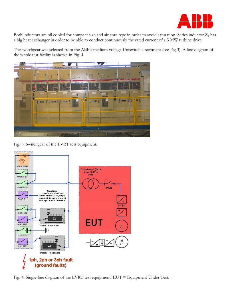
The switchgear was selected from the ABB's medium voltage Uniswitch assortment (see Fig 3). A line diagram of the whole test facility is shown in Fig. 4.
Fig. 3: Switchgear of the LVRT test equipment.
Fig. 4: Single-line diagram of the LVRT test equipment. EUT = Equipment Under Test.
The equipment normally is connected to Helsinki Energy's 20 kV line. The 110 kV sub-station is located close to the test site and, thus, realistic short-circuit ratio is possible to achieve. In addition to this fixed 50 Hz supply, a variable frequency and voltage supply from a variable speed 8 MVA synchronous machine is possible for turbines with 60 Hz rated frequency. With this machine, it also is possible to test other functions of the turbine, such as frequency support.
The equipment can be controlled through a computer-controlled interface (note Fig. 5). It is possible to select three-phase, two-phase or single-phase voltage dips. In addition to the duration of the dip, it is possible to select the exact instant during a voltage cycle when the breaker is closed. Further, it is possible to program a sequence of faults in order to emulate reclosing operations, and faults developing from single-phase earth faults to three-phase shorts. The current, voltage and power measurements are recorded and included in a measurement report automatically.
Fig. 5: Computer control interface of the LVRT equipment.
The speed of the generator is controlled by a variable speed AC motor drive. The parameters of the speed controller can be adjusted to emulate the dynamics of the pitch control. Thus, realistic speed increase and oscillations can be obtained during and after the dip.
LVRT testing of a full-power converter wind turbine drive
The first LVRT tests with the new test facility were made with a 2.3 MW full-power converter drive (see Fig. 6). Examples of the recorded zero-voltage, ride-through test waveforms are shown in Figures 7-9.
The generator was running at rated power before the dip. When the circuit breaker shorts the medium voltage side of the grid, the turbine starts immediately to supply reactive current. Due to the reactive current and the impedance of the transformer, the voltage on the low-voltage side of the turbine transformer, ULV, does not go to zero. After the breaker clears the short, the reactive current is reduced and active current is ramped up.
Fig. 6: Liquid cooled 2.3 MW full power converter.
Fig. 7: Example of a zero-voltage, ride-through test of a 2.3 MW full converter WT drive. RMS voltages and currents on the medium voltage (MV) and low voltage (LV) side of the transformer.
Fig. 8: Per-unit active and reactive currents during a zero voltage ride through test of a 2.3 MW full converter WT drive.
Fig. 9: Phase currents in the medium voltage side during a zero-voltage ride-through test of a 2.3 MW full converter WT drive.
In Fig. 9, the inrush current of the transformer, due to the heavy saturation, can be seen clearly after voltage recovery. The saturation distorts the low-voltage-side waveform considerably. In spite of this, the virtual Direct Torque Control (DTC) of the grid-side converter is able to control the situation without problems. However, the existence of this kind of phenomena highlights the necessity of full-scale testing of wind turbine drives.
Conclusions
ABB has built a new test facility capable of conducting low-voltage, ride-through tests for wind turbine drives with rated power up to 3 MW. The testing can be done efficiently due to highly automated test set-up. Thorough factory testing is expected to reduce the required on-site testing time and costs considerably.
References
1. TransmissionCode 2007. Network and System Rules of the German Transmission System Operators. BDEW, 2007 Aug.. [Online]. Available:
4. P.O. 12.3, Requisitos de respuesta frente a huecos de tensión de las instalaciones eólicas. Ministerio de Industria, Turismo y Comercio, Spain. [Online]. Available:
5. Niiranen, J.: Experiences on voltage dip ride through factory testing of synchronous and doubly fed generator drives. Proc. 11th European Conference on Power Electronics and Applications, EPE 2005, Dresden Germany, 11-14 September 2005. 11 p.
6. Niiranen, J.: About the Active and Reactive Power Measurements in Unsymmetrical Voltage Dip Ride Through Testing. Wind Energy 2008; 11:121-131
7. Seman, S., Niiranen, J., Virtanen, R, Matsinen, J-P.: Low Voltage Ride-Through Analysis of 2 MW DFIG Wind Turbine – Grid Code Compliance Validations. Proceedings of IEEE 2008 Power and Energy Society General Meeting - Conversion and Delivery of Electrical Energy in the 21st Century. 20-24 July 2008, Pittsburgh, PA, 6 pages.
8. IEC 61400-21. International standard. Wind turbines – Part 21. Measurement and assessment of power quality characteristics of grid connected wind turbines. (2nd edn). IEC Central Office: Geneva, Switzerland, 2008; 58 pp.