Technical Reference Electrical Engineering Safety EES-014 NSW DPI Technical Reference Technical Principles for the Use of “Stand Alone” Generators at NSW Mines (Coal and Metals) and Extractives Operations Coal Mine Health and Safety Act 2002 Coal Mine Health and Safety Regulation 2006 Occupational Health and Safety Regulation 2001 Occupational Health and Safety Act 2000 Mines Health and Safety Act 2004 Mines Health and Safety regulation 2007 February 2010 (version 2) Mine Safety Operations February 2010 EES014 Test before you touch Version 2 Page 1 of 27 No live line work
Transcript
Technical Reference Electrical Engineering Safety
EES-014
NSW DPI Technical Reference Technical Principles for the Use of “Stand Alone” Generators at NSW
Mines (Coal and Metals) and Extractives Operations
Coal Mine Health and Safety Act 2002 Coal Mine Health and Safety Regulation 2006
Occupational Health and Safety Regulation 2001 Occupational Health and Safety Act 2000
Mines Health and Safety Act 2004 Mines Health and Safety regulation 2007
February 2010 (version 2)
Mine Safety Operations February 2010 EES014 Test before you touch Version 2
Page 1 of 27 No live line work
Disclaimer
The compilation of information contained in this document relies upon material and data derived from a number of third party sources and is intended as a guide only in devising risk and safety management systems for the working of mines and is not designed to replace or be used instead of an appropriately designed safety management plan for each individual mine. Users should rely on their own advice, skills and experience in applying risk and safety management systems in individual workplaces.
Use of this document does not relieve the user (or a person on whose behalf it is used) of any obligation or duty that might arise under any legislation (including the Occupational Health & Safety Act 2000, any other Act containing requirements relating to mine safety and any regulations and rules under those Acts) covering the activities to which this document has been or is to be applied.
The information in this document is provided voluntarily and for information purposes only. The New South Wales Government does not guarantee that the information is complete, current or correct and accepts no responsibility for unsuitable or inaccurate material that may be encountered.
Unless otherwise stated, the authorised version of all reports, guides, data and other information should be sourced from official printed versions of the agency directly. Neither the Department of Industry and Investment, the New South Wales Government, nor any employee or agent of the Department, nor any author of or contributor to this document produced by the Department shall be responsible or liable for any loss, damage, personal injury or death howsoever caused.
Users should always verify historical material by making and relying upon their own separate inquiries prior to making any important decisions or taking any action on the basis of this information.
This publication contains information regarding occupational health, safety, injury management or workers compensation. It includes some of your obligations under the various workers compensation and occupational health and safety legislation that the Department of Industry and Investment administers. To ensure you comply with your legal obligations you must refer to the appropriate Legislation.
This publication may refer to NSW Legislation that has been amended or repealed. When reading this publication you should always refer to the latest laws. Information on the latest laws can be checked at www.legislation.nsw.gov.au or contact (02) 4931 6666.
Mine Safety Operations February 2010 EES014 Test before you touch Version 2
Coal Mines and Metalliferous Mines legislation allow mines to develop occupational health and safety management systems that will:
• Be appropriate for that organisation;
• Be integrated with other systems and core functions of the organisation;
• Improve the organisation’s overall safety performance;
• Assist the organisation to meet its legal responsibilities; and
• Improve the performance of a site or the industry by a range of actions.
Specific Department of Industry and Investment (‘the Department’) targets for electrical engineering safety within the mining industry are:
• Zero electrocutions.
• Zero deaths as a result of electric shock (eg falls because of receiving an electric shock).
• Zero permanent disabling injuries as a result of electric shock.
• Zero incurable burns from electricity.
• Zero gas/dust explosions with electricity as an ignition source.
• Zero fires that result in injury, death or evacuation of a mine or part of a mine, caused by the malfunction of electrical equipment.
• Zero injury or death from unintended operation of electrically powered or controlled equipment.
• Zero injury or death from failure to stop electrically powered or controlled equipment.
• Zero injury or death from the failure to operate electrically powered or controlled equipment.
Privately owned generating plant is widely used in NSW mining situations for numerous purposes. Large, polyphase standby installations tend to be engineered for the particular installation, with the legal requirements and engineering standards being well understood and taken into account by qualified electrical engineers.
Smaller transportable 240V generators, and some smaller fixed 415V generators, on the other hand, are frequently selected and used by persons without detailed knowledge of electrical safety standards, and as a result installations are designed according to “urban lore”. Equipment manufacturers are not providing adequate safety information with their equipment, and sellers and hirers are not properly advising their customers.
In many cases, electrical contractors do not understand the specific requirements for generator installations, and if there is no mains supply involved, then the Electricity Distributor has no jurisdiction, and cannot set minimum standards.
These notes are intended to bring together the various requirements and circuit design philosophies for generator installations, enabling Inspectors of Electrical Engineering to provide consistent advice to colleagues, electricity workers and consumers.
NOTE: This technical reference does not preclude generator installations at mines which have
been installed to a professionally engineered system and to the appropriate Australian Standards,
which may utilise safety principles/practices not necessarily covered in this simplified document.
Mine Safety operations electrical engineering staff will use this document as a minimum expectation for electrical systems and equipment installed at all types of mining operations.
Mine Safety Operations February 2010 EES014 Test before you touch Version 2
Page 3 of 27 No live line work
Consultants, designers and mine personnel should incorporate these requirements as a minimum. Where these requirements are not implemented alternative engineering risk controls must be applied and analysed to ensure that the alternative risk controls provide for a risk less than if the principles were applied in total.
This Technical Reference can also be used by mine operators to assess the effectiveness of their present arrangements for the use of generators.
This Technical Reference will assist employers, self-employed persons, employees, contractors and other parties involved with practices of designing and life-cycle management of electrical systems and equipment.
John Francis Waudby
Senior Inspector of Electrical Engineering
Mine Safety Operations February 2010 EES014 Test before you touch Version 2
Chapter 3 Generators under 25kW ..................................................................................................... 12 3.1 Background Information ................................................................................................................. 12 3.2 General Additional Safety Features for Mines: .............................................................................. 12 3.3 Single Phase Standalone Generator – With Residual Current Detection...................................... 13 3.4 Isolated Winding Generator with Integral Socket Outlets .............................................................. 14 3.5 Single Phase Generator with Fixed Installation Switchboard ........................................................ 15
Department Contact Details ..................................................................................................................... 27
Mine Safety Operations February 2010 EES014 Test before you touch Version 2
Page 5 of 27 No live line work
Chapter 1 Establishment
1.1 Title This is the Department of Industry and Investment Electrical Engineering Safety Technical Reference – Use of Stand Alone Generators at NSW Mines (Coal and Metals) and Extractives Operations.
1.2 Purpose This Technical Reference is intended to provide a framework for Departmental officers to assess stand alone generators and their connection to electrical installations at the operation. When mines or designers of electrical systems contact the Department for advice, this document will provide guidance on selecting generator arrangements for particular situations at mines. This document provides advice for persons with electrical qualifications. Arrangements nominated in this document, with the exception of plug and socket connections, must be installed by a competent tradesperson.
It can also be used by mine operators and designers as guidance material for implementing, managing or reviewing their requirements for stand alone generators and associated electrical installations.
The outcomes sought to be achieved by this Technical Reference are to protect people and property from the risks associated with the use of electricity in mining operations including:
• Electrocution
• Electric Shock
• Electrical burn injuries
• Arc blast injuries
• Injuries sustained through operation of the equipment
• Unintended operation of the equipment
• Fire
1.3 Scope
This Technical Reference extends to all mining and extractives operations in New South Wales. The range of equipment is single phase generators, single phase inverter systems for deriving 240 Volt supplies and multi-phase low voltage stand alone, relocatable generators.
NOTE: Lightning protection systems and their associated earthing mats do not lie within the scope of this document. In areas of high lightning activity, the provisions of AS/NZS 1768 should be considered.
1.4 Authority
This is an Electrical Engineering Safety Technical Reference and is recommended by the Department of Industry and Investment.
Mine Safety Operations February 2010 EES014 Test before you touch Version 2
Page 6 of 27 No live line work
1.5 Revisions This is the first revision of EES014. The following revisions have been made:
• For MEN generators >25 kW, Note 5, has been modified to clarify that the use of a four pole breaker instead of a three pole breaker is advantageous, not mandatory.
• Additional emphases have been made throughout the document stressing that “all of the safety measures & recommendations relevant for that configuration must be applied if EES014 is to be correctly utilised".
• A battery isolator has been added to the inverter circuit in Appendix A.
• The following recommendation is included in several places in the document: "Where a powered appliance is to be used with an extension lead, an additional 2.5mm2 equipotential bond should be run to any unbonded metal work associated with the use of that appliance ..."
• Appendix D concerning residual voltage protection has been removed as it is now out of date.
• For Generators > 25 kW, qualified allowance has been made to enable the primary protection earth leakage relay and circuit breaker to be replaced with a RCD circuit breaker. When this is done, the secondary earth leakage circuit should utilise an under-voltage coil, not a shunt trip mechanism.
• Other minor wording changes made for clarification purposes.
1.6 Definitions Active (or active conductor): Any conductor that is maintained at a difference of potential from the neutral or earthed conductor. In a system that does not include a neutral or earthed conductor, all conductors shall be considered to be active conductors.
Appliance: A consuming device other than a lamp, in which electricity is converted into heat, motion, or any other form of energy, or is substantially changed in its electrical character.
Class I Appliances: Protection from electric shock relies on insulation and conductive parts connected to the protective earthing conductor.
Class II Appliances: Protection from electric shock relies on double insulation or reinforced insulation, there being no provision for protective earthing.
Double Insulation: Insulation comprising both basic insulation and supplementary insulation.
Earthed: Connected to the general mass of earth.
Earth-leakage protection: Detects earth-leakage current and isolates the electrical supply from any fault zone.
Equipotential Bonding Conductor: Electrical connections intended to bring exposed conductive parts or extraneous conductive parts to the same or approximately the same potential, but not intended to carry current in normal service.
Generating Set: An alternator, d.c. generator, or combination thereof, including any internal combustion engine and associated switchgear and control gear.
“IT” Earthing: A power system having the earthable point not connected to earth, or connected to earth through an impedance (resistor), the exposed conductive parts of the installation being connected to earth electrodes which may be the same as those used for the earthing resistor (Section 3 of AS 3007.2).
Licensed electrician: A person who is the holder of a Qualified Supervisor Certificate – Electrician as defined under the Home Building Act 1989.
Multiple Earthed Neutral (MEN) System: A system of earthing in which the parts of an electrical installation required to be earthed in accordance with AS/NZS 3000:2007 are connected together to form
Mine Safety Operations February 2010 EES014 Test before you touch Version 2
Page 7 of 27 No live line work
an equipotential bonded network and this network is connected to both the neutral conductor of the supply system and the general mass of earth.
Neutral (or neutral conductor): The conductor of a three-wire or multi-wire system that is maintained at an intermediate and approximately uniform potential in respect of the active or outer conductors, or the conductor of a two-wire system that is connected to earth at its origin.
Socket Outlet: A device for fixing or suspension at a point, and having contacts intended for making a detachable connection with the contacts of a plug. The term socket outlet is deemed to include a cord extension socket attached to a flexible cord which is permanently connected to fixed wiring.
Stand-alone Power Systems: Power systems that are not connected to the power distribution systems of an electricity supply authority. Stand-alone systems are supplied with power from one or more of a number of sources, including, but not limited to, a photovoltaic array, a wind turbine generator, a micro-hydro generator and an engine generator set.
Residual Current Device (RCD): A device intended to isolate supply to protected circuits, socket outlets or electrical equipment in the event of a current flow to earth that exceeds a predetermined value.
Touch voltage: Voltage appearing between simultaneously accessible parts.
“TN” Earthing: A power system having the earthable point directly connected to earth and the exposed conductive parts of the installation being connected by protective conductors to the earthable point of the power system (For further information see Section 3 of AS 3007.2).
Voltage:
Extra low voltage* – Not exceeding 50V a.c. or 120V ripple free d.c.
Low voltage* – Exceeding extra low voltage, but not exceeding 1000V a.c. or 1500V d.c
High voltage* – Exceeding low voltage.
* Definitions as per AS/NZS 3000:2007.
1.7 Applicable legislation
The Occupational Health and Safety Act 2000
The Occupational Health and Safety Regulation 2001
The Coal Mine Health and Safety Act 2002
The Coal Mine Health and Safety Regulation 2006
The Mine Health and Safety Act 2004
The Mine Health and Safety Regulation 2007
1.8 Referenced Gazette Notices
N/A
1.9 Referenced Standards and Guidelines AS 2790:1989 Electricity generating sets – Transportable (Up to 25 kW)
AS/NZS 3000:2007 W iring Rules
AS 3007 Series - Electrical installations - Surface mines and associated processing plant
EES005 NSW DPI Technical Reference - Electrical Protection and Earthing
1.10 Acronyms
AS – Australian Standard AS/NZS – Australian New Zealand Standard E/L – Earth leakage RCD – Residual current device (RCD) GPO - General Purpose Outlet
Mine Safety Operations February 2010 EES014 Test before you touch Version 2
Page 9 of 27 No live line work
Chapter 2 Electrical Engineering Background
2.1 Protection against electric shock Under the heading “Protection against electric shock” AS/NZS3000:2007 states:
Protection shall be provided against shock current arising from contact with parts that are live in normal service (direct contact) or parts that become live under fault conditions (indirect contact). Therefore, live parts must not be accessible and accessible conductive parts must not be live, neither under normal conditions nor under single fault conditions.
The following sections of this document outline various electrical engineering methods to provide the essential requirements primarily regarding protection against indirect contact electric shock including basic protection and fault protection. They also deal with the application of these requirements in relation to external influences, such as damp situations often found in mining applications.
For protection against indirect contact, protection can be by a combination of either/or:
• Automatically disconnecting supply under fault conditions • Using Class II equipment • Electrical separation
If automatic disconnection is chosen, a system must be provided in which all external conductive parts are electrically bonded; with some systems also being effectively earthed with an earth electrode. Automatic fault disconnection is provided via circuit breakers, fuses, RCD etc.
If Electrical Separation is chosen, the generator is treated the same as an isolation transformer, with the installation isolated from earth. In this configuration an RCD will not operate and therefore is not used (AS/NZS 3000:2007 Fig. 7.7 Note 4). Such systems can provide increased protection for Class II equipment ie. double insulated tools.
2.2 Optional Configurations
Therefore, the consumer can choose the most suitable installation configuration for their particular application. In making the choice, the consumer is committing to a particular protection strategy and must maintain that protection strategy throughout the installation. Each configuration comes with a set of requirements and recommendations that must be observed to maintain the optimum safety of the installation.
The options available to the consumer are: • MEN System of earthing. • Unearthed (separated supply), single appliance. • Unearthed (separated supply), multiple appliance. • IT System of Earthing.
Safety Note
Once the installation configuration is chosen, all of the safety measures & recommendations relevant for that configuration must be applied if EES014 is to be correctly utilised.
Selecting some features from one configuration and some features from another will not assure the safety of the installation.
Mine Safety Operations February 2010 EES014 Test before you touch Version 2
Page 10 of 27 No live line work
2.3 Installation Design Considerations
Other generic design considerations which are not extensively referenced as a part of this document include topics such as; protection against direct electrical contact including isolation, maximum demand requirements, cable and circuit breaker ratings, voltage drop and electrical installation standards etc. For these topics, the reader is referred to AS/NZS 3000:2007, AS 3007.1-5:2004 & AS 3012:2003.
Mine Safety Operations February 2010 EES014 Test before you touch Version 2
Page 11 of 27 No live line work
Chapter 3 Generators under 25kW
3.1 Background Information
Generators under 25 kW must satisfy the requirements of AS 2790-1989 “Electrical generating sets-Transportable (Up to 25 kW)”. Their installation and application can vary significantly, however the guiding principles for their use can be found in AS/NZS 3012:2003 “Electrical installations – Construction and demolition sites”.
NOTE: Due to the specialised requirements of mine sites, the following additional safety features are recommended by the Department when utilising AS/NZS 3012:2003 as a generator installation standard.
3.2 General Additional Safety Features for Mines: • Where a powered appliance is to be used with an extension lead, an additional 2.5mm2
equipotential bond should be run to any unbonded metal work associated with the use of that appliance eg. When using a power tool on a light vehicle, the metal body of that vehicle should be equipotentially bonded back to the generator.
• To achieve “best practice” all extension leads used in a mining environment must be screened leads and fitted with IP56 plugs and sockets. The safety principles utilised in this document depend in part on the use of screened leads. The screen of extension leads MUST be connected to the earth terminals at both the plug and sockets ends.
• All power outlets should have a minimum IP rating of 56. • IP56 rated plugs should be fitted to tools. • Where possible, RCDs protecting general purpose outlets (GPOs) should be rated at 10mA,
and no more than 30mA. • Where multiple appliances or multiple items of fixed equipment are to be connected to a
generator supply, it will be necessary to select either an MEN or IT earthed configuration fitted with RCD protection.
Mine Safety Operations February 2010 EES014 Test before you touch Version 2
Page 12 of 27 No live line work
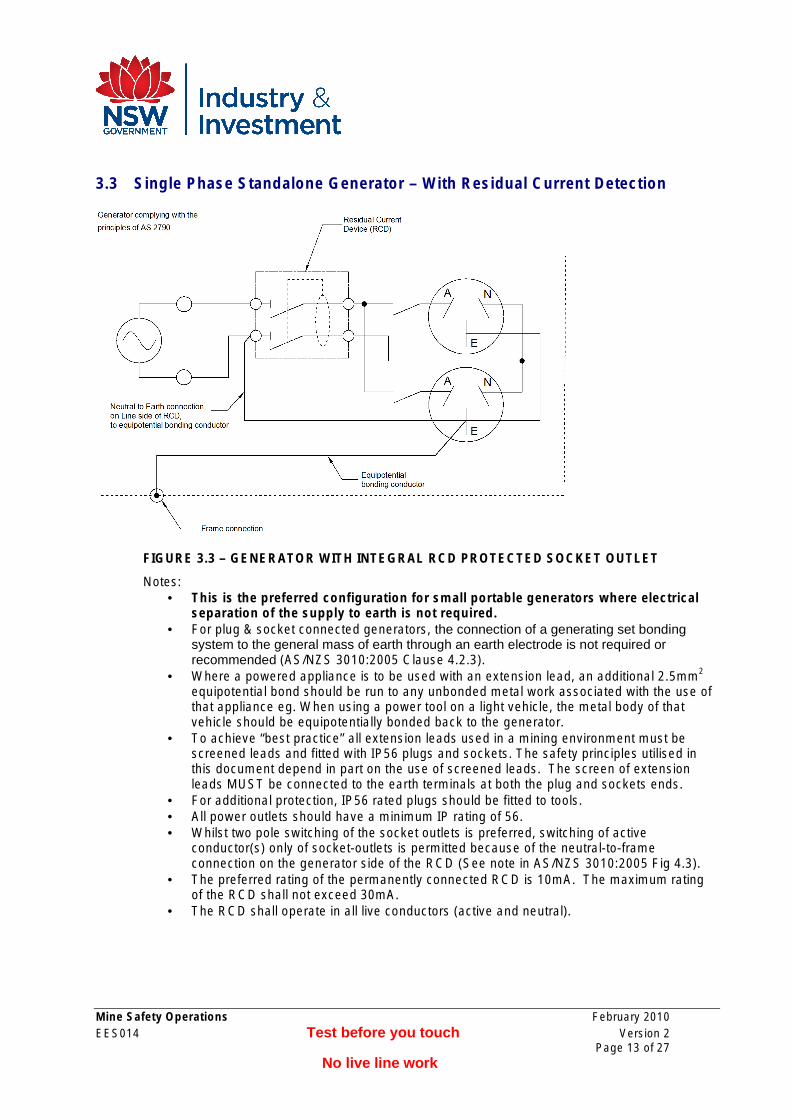
3.3 Single Phase Standalone Generator – With Residual Current Detection
FIGURE 3.3 – GENERATOR WITH INTEGRAL RCD PROTECTED SOCKET OUTLET
Notes: • This is the preferred configuration for small portable generators where electrical
separation of the supply to earth is not required. • For plug & socket connected generators, the connection of a generating set bonding
system to the general mass of earth through an earth electrode is not required or recommended (AS/NZS 3010:2005 Clause 4.2.3).
• Where a powered appliance is to be used with an extension lead, an additional 2.5mm2
equipotential bond should be run to any unbonded metal work associated with the use of that appliance eg. When using a power tool on a light vehicle, the metal body of that vehicle should be equipotentially bonded back to the generator.
• To achieve “best practice” all extension leads used in a mining environment must be screened leads and fitted with IP56 plugs and sockets. The safety principles utilised in this document depend in part on the use of screened leads. The screen of extension leads MUST be connected to the earth terminals at both the plug and sockets ends.
• For additional protection, IP56 rated plugs should be fitted to tools. • All power outlets should have a minimum IP rating of 56. • Whilst two pole switching of the socket outlets is preferred, switching of active
conductor(s) only of socket-outlets is permitted because of the neutral-to-frame connection on the generator side of the RCD (See note in AS/NZS 3010:2005 Fig 4.3).
• The preferred rating of the permanently connected RCD is 10mA. The maximum rating of the RCD shall not exceed 30mA.
• The RCD shall operate in all live conductors (active and neutral).
Mine Safety Operations February 2010 EES014 Test before you touch Version 2
Page 13 of 27 No live line work
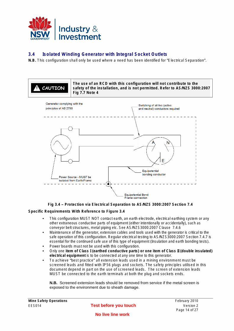
3.4 Isolated Winding Generator with Integral Socket Outlets N.B. This configuration shall only be used where a need has been identified for “Electrical Separation”.
The use of an RCD with this configuration will not contribute to the safety of the installation, and is not permitted. Refer to AS/NZS 3000:2007 Fig 7.7 Note 4
Fig 3.4 – Protection via Electrical Separation to AS/NZS 3000:2007 Section 7.4
Specific Requirements With Reference to Figure 3.4
• This configuration MUST NOT contact earth, an earth electrode, electrical earthing system or any other extraneous conductive parts of equipment (either intentionally or accidentally), such as conveyor belt structures, metal piping etc. See AS/NZS3000:2007 Clause 7.4.6
• Maintenance of the generator, extension cables and tools used with the generator is critical to the safe operation of this configuration. Regular electrical testing to AS/NZS3000:2007 Section 7.4.7 is essential for the continued safe use of this type of equipment (Insulation and earth bonding tests).
• Power boards must not be used with this configuration. • Only one item of Class I (earthed conductive parts) or one item of Class II (double insulated)
electrical equipment is to be connected at any one time to this generator. • To achieve “best practice” all extension leads used in a mining environment must be
screened leads and fitted with IP56 plugs and sockets. The safety principles utilised in this document depend in part on the use of screened leads. The screen of extension leads MUST be connected to the earth terminals at both the plug and sockets ends.
N.B. Screened extension leads should be removed from service if the metal screen is exposed to the environment due to sheath damage.
Mine Safety Operations February 2010 EES014 Test before you touch Version 2
Page 14 of 27 No live line work
• For additional protection, IP56 rated plugs should be fitted to tools. • All power outlets should have a minimum IP rating of 56. • The earth contact of every socket must be connected to the bonding conductor. • The designated earth conductor in any cable or cord must be used as the bonding conductor. • Exposed metal parts of mains powered equipment must not be simultaneously accessible
with exposed metal parts of the generator fed equipment.
• The supply from the generator should be protected against short circuit faults. If this protection is not built into the design of the generator, a suitably rated circuit breaker (or fuses) will be required.
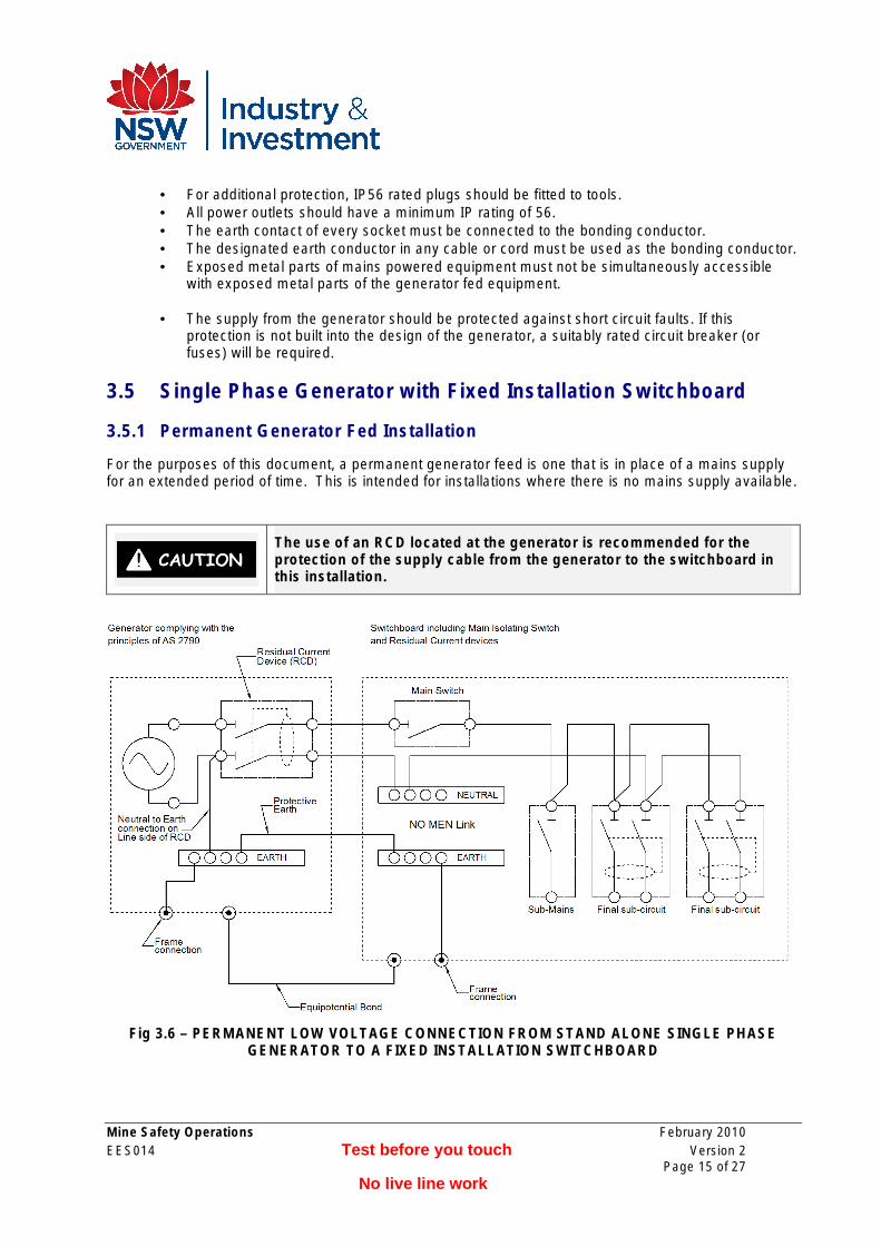
3.5 Single Phase Generator with Fixed Installation Switchboard
3.5.1 Permanent Generator Fed Installation
For the purposes of this document, a permanent generator feed is one that is in place of a mains supply for an extended period of time. This is intended for installations where there is no mains supply available.
The use of an RCD located at the generator is recommended for the protection of the supply cable from the generator to the switchboard in this installation.
Fig 3.6 – PERMANENT LOW VOLTAGE CONNECTION FROM STAND ALONE SINGLE PHASE GENERATOR TO A FIXED INSTALLATION SWITCHBOARD
Mine Safety Operations February 2010 EES014 Test before you touch Version 2
Page 15 of 27 No live line work
Additional Requirements to Fig 3.6
• The supply cable between the generator and the switchboard must be protected against short circuit faults. If this protection is not built into the design of the generator, a suitably rated circuit breaker (or fuses) will be required.
• The connection of a generating set bonding system to the general mass of earth through an earth electrode is not required or recommended (AS/NZS 3010:2005 Clause 4.2.3).
• Where practicable, all the earthing points, other than for lightning protection, should be electrically bonded together (Refer AS/NZS 3000:2007 Section 5.8).
• Where a powered appliance is to be used with an extension lead, an additional 2.5mm2
equipotential bond should be run to any unbonded metal work associated with the use of that appliance eg. When using a power tool on a light vehicle, the metal body of that vehicle should be equipotentially bonded back to the generator.
• To achieve “best practice” all extension leads used in a mining environment must be screened leads and fitted with IP56 plugs and sockets. The safety principles utilised in this document depend in part on the use of screened leads. The screen of extension leads MUST be connected to the earth terminals at both the plug and sockets ends.
• For additional protection, IP56 rated plugs should be fitted to any tools. • The only earth reference connection to the generator windings shall be made at the generator
terminal box. No MEN connection shall be made between the switchboard Neutral Link and the Earth Link.
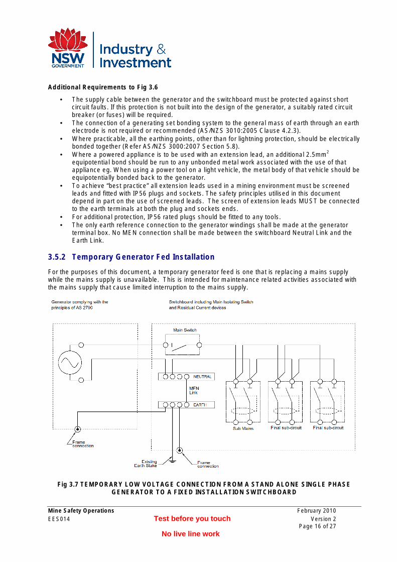
3.5.2 Temporary Generator Fed Installation
For the purposes of this document, a temporary generator feed is one that is replacing a mains supply while the mains supply is unavailable. This is intended for maintenance related activities associated with the mains supply that cause limited interruption to the mains supply.
Fig 3.7 TEMPORARY LOW VOLTAGE CONNECTION FROM A STAND ALONE SINGLE PHASE GENERATOR TO A FIXED INSTALLATION SWITCHBOARD
Mine Safety Operations February 2010 EES014 Test before you touch Version 2
Page 16 of 27 No live line work
Additional Requirements for reference to Fig 3.7
• The generator and switchboard should ideally be located as close as possible to each other. Alternately, an additional equipotential bond of the same size as the power conductors can be used between the generator casing and the switchboard.
• The cable between the generator and the switchboard should be armoured, or mechanically protected to an equivalent level, and as short as reasonably practical.
• The supply cable between the generator and the switchboard must be protected against short circuit faults. If this protection is not built into the design of the generator, a suitably rated circuit breaker (or fuses) will be required.
• The earth stake installed to AS/NZS 3000:2007 Section 5.3.6 at the main switchboard may be left in place while the generator is connected in place of the mains supply.
• Where practicable, all the earthing points, other than for lightning protection, should be electrically bonded together (Refer AS/NZS 3000:2007 Section 5.8).
• Where a powered appliance is to be used with an extension lead, an additional 2.5mm2
equipotential bond should be run to any unbonded metal work associated with the use of that appliance eg. When using a power tool on a light vehicle, the metal body of that vehicle should be equipotentially bonded back to the generator.
• To achieve “best practice” all extension leads used in a mining environment must be screened leads and fitted with IP56 plugs and sockets. The safety principles utilised in this document depend in part on the use of screened leads. The screen of extension leads MUST be connected to the earth terminals at both the plug and sockets ends.
• For additional protection, IP56 rated plugs should be fitted to any tools. • The only earth reference connection to the generator windings shall be made at the MEN link of
the switchboard. No earthing connection to the windings shall be made at the generator.
Mine Safety Operations February 2010 EES014 Test before you touch Version 2
Page 17 of 27 No live line work
Chapter 4 Standalone Generators Larger than 25kW
4.1 Scope: • This document does not exclude the possibility of more complex engineered solutions eg
pilot and cable fault lock-out systems, fully engineered earth mats etc. • This document does not address the issue of generating systems used in association with
mains powered supplies e.g. power back-up generators for grid connected installations. Notes:
• The primary objective of this document is to enable mines or quarries to install relocatable power generating sets in such a way as to limit all prospective touch voltages to below the maximum values as set forth in Fig. B4 AS/NZS3000:2007, and in particular the “Lp” curve for wet conditions.
• All generating systems covered in this document shall be connected to the installation in such a manner that they remain isolated from the Supply Authority system or any other electrical generating system.
• All electrical connections, other than via plugs and sockets, shall be made by suitably qualified electrical personnel and shall be verified as per AS/NZS 3000:2007 Section 8.
• Where practicable, all the earthing points, other than for lightning protection, should be electrically bonded together (Refer AS/NZS 3000:2007 Section 5.8).
4.2 General Additional Requirements for Mines:
• It is recommended that all power cables above ELV be multicore armoured or screened cables for added safety against direct and indirect shock.
• Where a powered appliance is to be used with an extension lead, an additional 2.5mm2
equipotential bond should be run to any unbonded metal work associated with the use of that appliance eg. When using a power tool on a light vehicle, the metal body of that vehicle should be equipotentially bonded back to the generator.
• To achieve “best practice” all extension leads used in a mining environment must be screened leads and fitted with IP56 plugs and sockets. The safety principles utilised in this document depend in part on the use of screened leads. The screen of extension leads MUST be connected to the earth terminals at both the plug and sockets ends.
• For additional protection, IP56 rated plugs should be fitted to any tools. • All power outlets to have a minimum IP rating of 56. • Where possible, the use of 10mA RCDs on 240V general purpose socket outlets (GPOs) is
preferred, although RCDs not exceeding 30mA are permitted. • 415V three phase socket outlets to be protected by maximum of 100mA RCDs.
Mine Safety Operations February 2010 EES014 Test before you touch Version 2
Page 18 of 27 No live line work
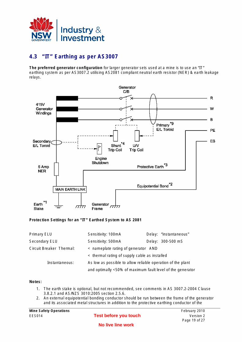
4.3 “IT” Earthing as per AS3007
The preferred generator configuration for larger generator sets used at a mine is to use an “IT” earthing system as per AS3007.2 utilising AS2081 compliant neutral earth resistor (NER) & earth leakage relays.
Protection Settings for an “IT” Earthed System to AS 2081
Primary ELU Sensitivity: 100mA Delay: “instantaneous”
Secondary ELU Sensitivity: 500mA Delay: 300-500 mS
Circuit Breaker Thermal: < nameplate rating of generator AND
< thermal rating of supply cable as installed
Instantaneous: As low as possible to allow reliable operation of the plant
and optimally <50% of maximum fault level of the generator
Notes:
1. The earth stake is optional, but not recommended, see comments in AS 3007.2-2004 Clause 3.8.2.1 and AS/NZS 3010:2005 section 2.5.6.
2. An external equipotential bonding conductor should be run between the frame of the generator and its associated metal structures in addition to the protective earthing conductor of the
Mine Safety Operations February 2010 EES014 Test before you touch Version 2
Page 19 of 27 No live line work
multicore supply cable. For mechanical strength, this conductor should be at least 35mm2. This cable should be visually inspected on a daily basis.
3. The resistance of the protective earthing conductor should be less than 0.50. 4. Ideally, a shunt trip, driven by the secondary earth leakage relay should be provided on the
generator circuit breaker in addition to the under voltage trip driven by the primary earth leakage. 5. The secondary ELU should operate a flag relay (for indication purposes) & shut down the driving
motor. 6. Typically the short circuit rating of a generator falls rapidly to only 3 X the full load current. Care
needs to be taken with the selection of the main circuit breaker to match the generator fault load characteristics to ensure that short circuit faults can be detected and cleared. Most circuit breakers with electronic overloads can be “programmed” to accommodate for the specific requirements of generator protection.
7. It is not permitted to utilise the transformer star point to reticulate 240V supplies from this system. 8. Should this arrangement be used with fixed plant, care should be taken to ensure that there is no
MEN link in the associated switchboard. 9. Where the generator output rating and fault level is low enough to enable the safe use of RCDs
on each output, the primary earth leakage toroid and associated trip coil may be replaced by an RCD(s). Where this option is exercised, an under volt trip coil should replace the shunt trip for the secondary earth leakage trip circuit.
Advantages of “IT” Earthing
a) This is the safest option with greatly reduced touch and step potentials which is particularly important in damp environments.
b) The electrical engineering is done largely by the supplier. c) Eliminates the possible need for expensive earthing systems. d) Low energy earth faults result in minimal damage to equipment and reduced likelihood of an arc
blast incident. e) Less stringent earth fault trip times can be utilised to assist with difficult motor starting
applications (A maximum back up trip time of 500 mS is permitted with an “IT” system).
Disadvantage of “IT” Earthing
a) Higher initial cost of equipment. b) Any 240 Volt supply must have a separate “IT” source ie a separate 415 to 240 Volt transformer
with the appropriate RCD protection. Reticulation of 240 Volts by utilising the 415V supply neutral is not permitted.
Mine Safety Operations February 2010 EES014 Test before you touch Version 2
Page 20 of 27 No live line work
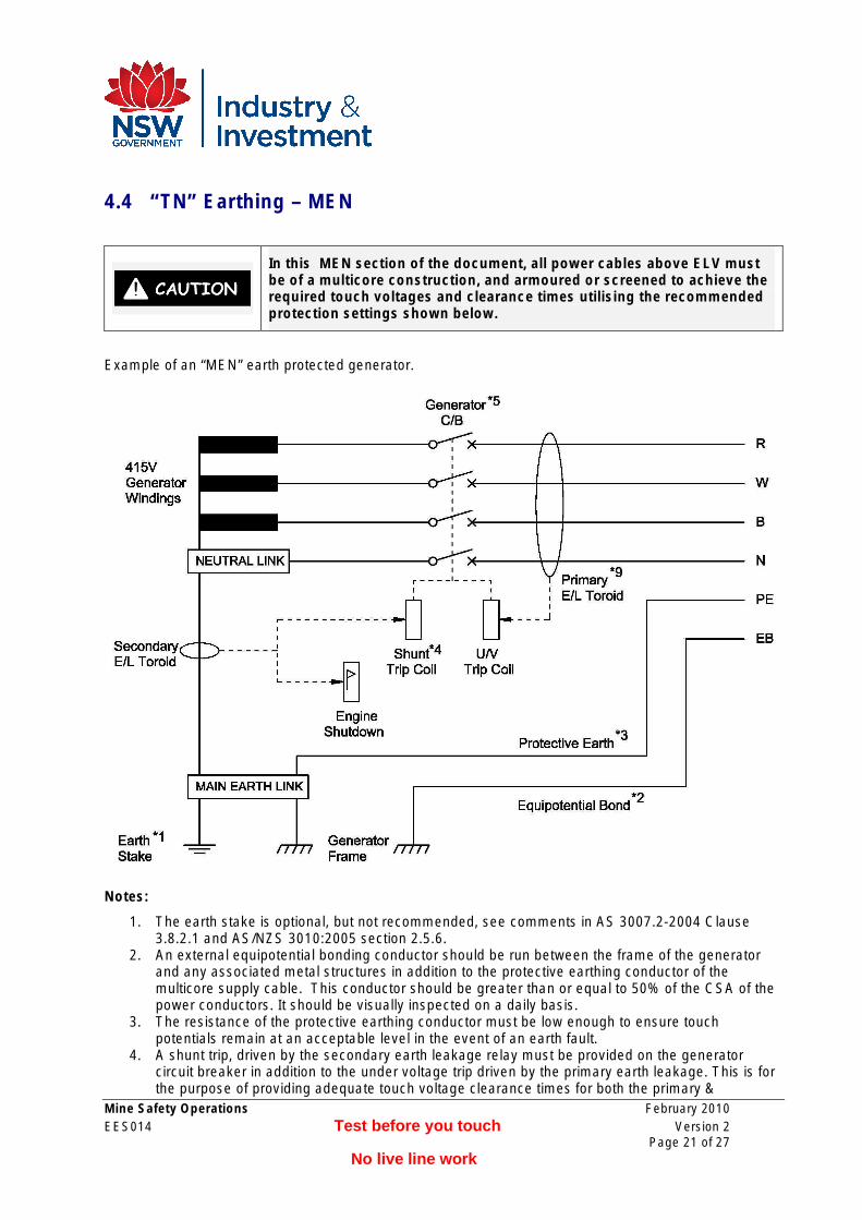
4.4 “TN” Earthing – MEN
In this MEN section of the document, all power cables above ELV must be of a multicore construction, and armoured or screened to achieve the required touch voltages and clearance times utilising the recommended protection settings shown below.
Example of an “MEN” earth protected generator.
Notes:
1. The earth stake is optional, but not recommended, see comments in AS 3007.2-2004 Clause 3.8.2.1 and AS/NZS 3010:2005 section 2.5.6.
2. An external equipotential bonding conductor should be run between the frame of the generator and any associated metal structures in addition to the protective earthing conductor of the multicore supply cable. This conductor should be greater than or equal to 50% of the CSA of the power conductors. It should be visually inspected on a daily basis.
3. The resistance of the protective earthing conductor must be low enough to ensure touch potentials remain at an acceptable level in the event of an earth fault.
4. A shunt trip, driven by the secondary earth leakage relay must be provided on the generator circuit breaker in addition to the under voltage trip driven by the primary earth leakage. This is for the purpose of providing adequate touch voltage clearance times for both the primary &
Mine Safety Operations February 2010 EES014 Test before you touch Version 2
Page 21 of 27 No live line work
secondary trip circuits. This requirement may be waived only where the generator output rating and fault level is suitable to enable the safe use of RCDs on each output (See note 9).
5. An earth fault on the neutral conductor can result in tripping of the secondary earth leakage system, resulting in a fault that is difficult to locate. Provision of a four pole main circuit breaker (interrupting the neutral as well as the three phases) can help mitigate this problem.
6. The secondary ELU should operate a flag relay (for indication purposes) & shut down the driving motor.
7. With this system of earthing the touch potential is determined by the voltage output of the generator under fault conditions and the impedance dividing network of the generator, power conductor, fault impedance, protection earth impedance, and possibly the earth return impedance via an earth stake if used.
8. Should this arrangement be used with fixed plant, care should be taken to ensure no MEN link is installed in the associated switchboard.
9. Where the generator output rating and fault level suitable to enable the safe use of RCDs on each output, the primary earth leakage toroid and associated trip coil may be replaced by an RCD(s). Where this option is exercise, an under volt trip coil should replace the shunt trip for the secondary earth leakage trip circuit.
Assumptions Taken:
• Circuit breaker is of a type suitable for use with generators. • The typical short circuit current of a three phase power generator is “x 10” for 10mSec & “x 3”
for 100mSec. • The typical voltage dip at the generator due to a low impedance fault to earth is
approximately 35%. • The fastest reasonable clearance time for a circuit breaker and earth leakage relay is
150 mS. Faster clearance times may be achieved through the use of RCDs in lower power and fault level applications.
• The power cable runs from the generator are relatively short, normally less than 50m. • The primary ELU is set to instantaneous trip.
N.B. By utilising armoured or screened cables to reduce touch potentials under fault conditions, the total allowable clearance time for a 415V generator can be as slow as 200 mS and still comply with AS/NZS 3000:2007 Appendix B for wet areas.
Advantages of “TN” Earthing
a) Equipment is more readily available.
Disadvantage of “TN” Earthing
a) Prospective touch voltages during an earth fault can be high, requiring faster acting protection equipment to ensure an installation remains safe.
b) Larger earthing conductors are required to carry prospective fault currents while still maintaining acceptable levels of touch voltage.
c) A maximum earth fault clearance time of 200 mS may present problems when starting some high inertia loads.
d) Higher arc fault exposure.
Mine Safety Operations February 2010 EES014 Test before you touch Version 2
Page 22 of 27 No live line work
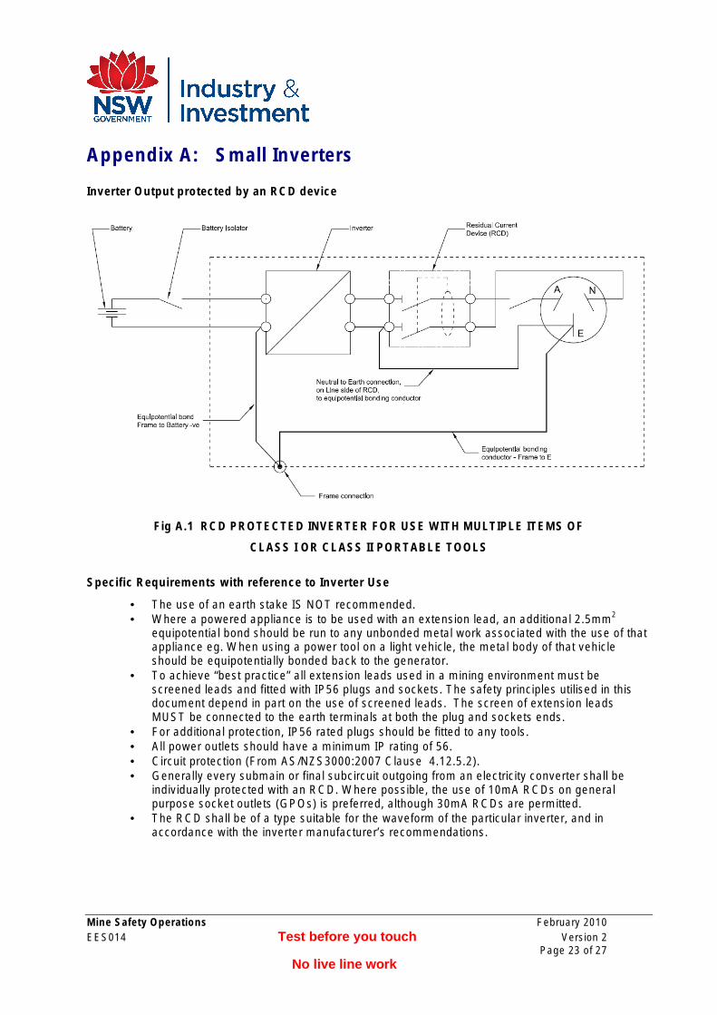
Appendix A: Small Inverters
Inverter Output protected by an RCD device
Fig A.1 RCD PROTECTED INVERTER FOR USE WITH MULTIPLE ITEMS OF
CLASS I OR CLASS II PORTABLE TOOLS
Specific Requirements with reference to Inverter Use
• The use of an earth stake IS NOT recommended. • Where a powered appliance is to be used with an extension lead, an additional 2.5mm2
equipotential bond should be run to any unbonded metal work associated with the use of that appliance eg. When using a power tool on a light vehicle, the metal body of that vehicle should be equipotentially bonded back to the generator.
• To achieve “best practice” all extension leads used in a mining environment must be screened leads and fitted with IP56 plugs and sockets. The safety principles utilised in this document depend in part on the use of screened leads. The screen of extension leads MUST be connected to the earth terminals at both the plug and sockets ends.
• For additional protection, IP56 rated plugs should be fitted to any tools. • All power outlets should have a minimum IP rating of 56. • Circuit protection (From AS/NZS3000:2007 Clause 4.12.5.2). • Generally every submain or final subcircuit outgoing from an electricity converter shall be
individually protected with an RCD. Where possible, the use of 10mA RCDs on general purpose socket outlets (GPOs) is preferred, although 30mA RCDs are permitted.
• The RCD shall be of a type suitable for the waveform of the particular inverter, and in accordance with the inverter manufacturer’s recommendations.
Mine Safety Operations February 2010 EES014 Test before you touch Version 2
Page 23 of 27 No live line work
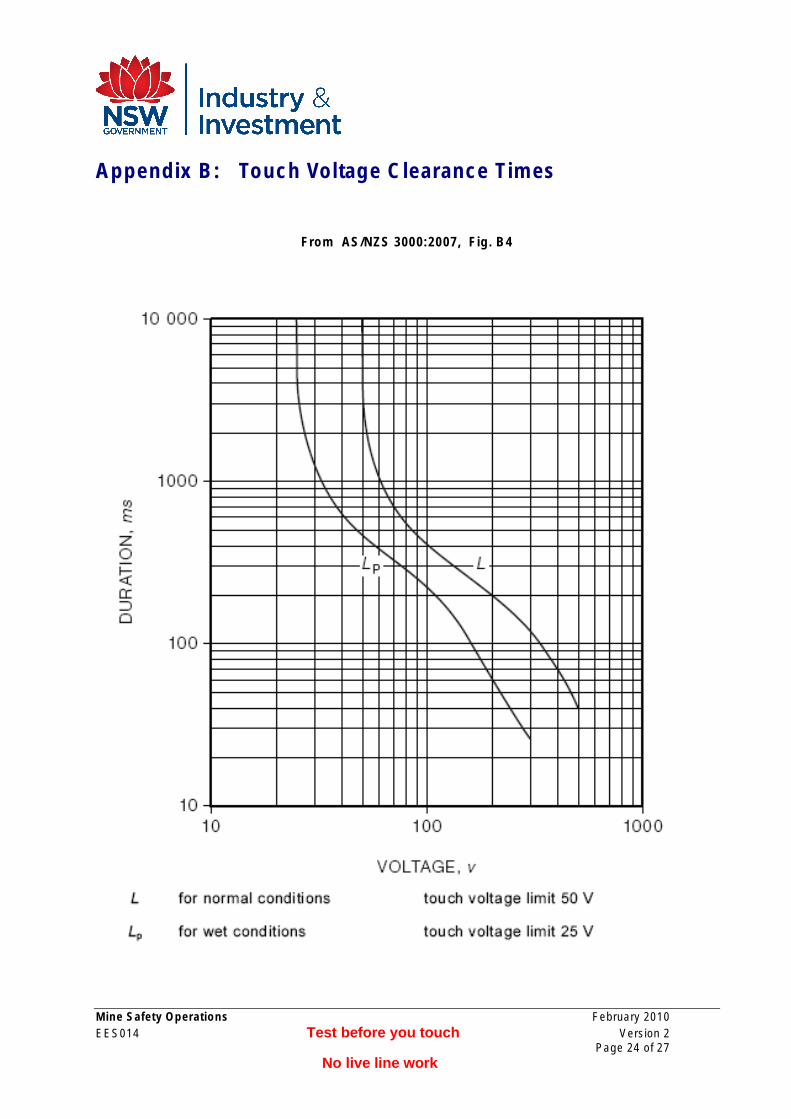
Appendix B: Touch Voltage Clearance Times
From AS/NZS 3000:2007, Fig. B4
Mine Safety Operations February 2010 EES014 Test before you touch Version 2
Page 24 of 27 No live line work
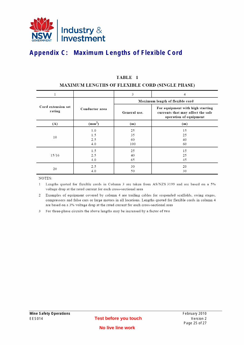
Appendix C: Maximum Lengths of Flexible Cord
Mine Safety Operations February 2010 EES014 Test before you touch Version 2
Page 25 of 27 No live line work
Feedback Sheet
Your comments will be very helpful in reviewing and improving this document.
Please copy and complete the Feedback Sheet and return it to:
Senior Inspector Electrical Engineering Mine Safety Operations Department of Industry and investment PO Box 344 MAITLAND NSW 2310 Fax: (02) 4931 6790 Phone: (02) 4931 6641
How did you use, or intend to use, this document?
What do you find most useful about this document?
What do you find least useful?
Do you have any suggested changes to the document?
Thank you for completing and returning this Feedback Sheet.
Mine Safety Operations February 2010 EES014 Test before you touch Version 2
Page 26 of 27 No live line work
Area
NSW DPI Contact Details
Department of Industry and Investment Mineral Resources offices located in mining regions
Armidale Department of Industry and Investment Earth Sciences Building (C2) University of New England Armidale NSW 2350 Phone: (02) 6738 8500 Fax: (02) 6772 8664
Broken Hill Level 2, 32 Sulphide Street Broken Hill NSW 2880 PO Box 696 Broken Hill NSW 2880 Phone: (08) 8088 9300 Fax: (08) 8087 8005
Cobar Government Offices 62-64 Marshall Street Cobar NSW 2835 PO Box 157 Cobar NSW 2835 Phone: (02) 6836 4392 Fax: (02) 6836 4395
Lightning Ridge Lot 60 Morilla Street Lightning Ridge NSW 2834 PO Box 314 Lightning Ridge NSW 2834 Phone: (02) 6829 0678 Fax: (02) 6829 0825
Lithgow Suite 1, 1st Floor, 184 Mort Street Lithgow NSW 2790 Phone: (02) 6350 7888 Fax: (02) 6352 3876
Maitland 516 High Street Maitland NSW 2320 PO Box 344 Hunter Regional Mail Centre NSW 2310 Phone: (02) 4931 6666 Fax: (02) 4931 6790