68
TECHNICAL PUBLICATIONS ® Operator's Manual Piercing Tools Issue 1.1 960-2000 Original Instruction

TECHNICAL PUBL ICAT IONS
®
Operator'sManual
Piercing Tools
Issue 1.1 960-2000Original Instruction

Piercing Tools Operator’s Manual
Overview
Chapter Contents
Serial Number Location . . . . . . . . . . . . . . . . . . . . . . 2
Intended Use . . . . . . . . . . . . . . . . . . . . . . . . . . . . . . . 3
Equipment Modification . . . . . . . . . . . . . . . . . . . . . . 3
Unit Components . . . . . . . . . . . . . . . . . . . . . . . . . . . 4
Operator Orientation. . . . . . . . . . . . . . . . . . . . . . . . . 5
Operating Area . . . . . . . . . . . . . . . . . . . . . . . . . . . . . 5
About This Manual . . . . . . . . . . . . . . . . . . . . . . . . . . 6
Overview - 1

Piercing Tools Operator’s ManualSerial Number Location
Serial Number Location
Record serial numbers and date of purchase in spaces provided.
Model Number
Serial Number
Date of purchase
2 - Overview
Piercing Tools Operator’s ManualIntended Use
Intended Use
HammerHead® piercing tools are intended to bore underground holes of 2” (50 mm) to 8” (200 mm) in diameter and up to 50’ (15 m) in length, and install utilities under existing landscapes and/or structures.
The unit is designed for operation in temperatures typically experienced in earth moving and construction work environments. Provisions may be required to operate in extreme temperatures. Contact your HammerHead dealer. Use in any other way is considered contrary to the intended use.
HammerHead piercing tools should be operated, serviced, and repaired only by persons familiar with their particular characteristics and acquainted with the relevant safety procedures.
Equipment Modification
This equipment was designed and built in accordance with applicable standards and regulations. Modification of equipment could mean that it will no longer meet regulations and may not function properly or in accordance with the operating instructions. Modification of equipment should only be made by competent personnel possessing knowledge of applicable standards, regulations, equipment design functionality/requirements and any required specialized testing.
Overview - 3
Piercing Tools Operator’s ManualUnit Components
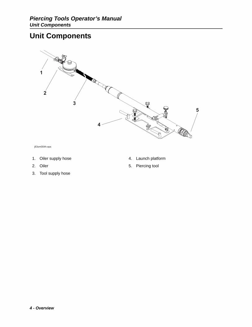
Unit Components
1. Oiler supply hose
2. Oiler
3. Tool supply hose
4. Launch platform
5. Piercing tool
4 - Overview

Piercing Tools Operator’s ManualOperator Orientation
Operator Orientation
1. Front of unit
2. Right side of unit
3. Rear of unit
4. Left side of unit
Operating Area
There is no designated operating position for the tool.
IMPORTANT: Top view of unit is shown.
IMPORTANT: Top view of unit is shown.
NOTICE: Follow U.S. Department of Labor regulations on excavating and trenching (Part 1926, Subpart P) and other similar regulations.
j63om007h.epsj63om007h.eps
Overview - 5

Piercing Tools Operator’s ManualAbout This Manual
About This Manual
This manual contains information for the proper use of this machine. Cross references such as “See page 50” will direct you to detailed procedures.
Bulleted Lists
Bulleted lists provide helpful or important information or contain procedures that do not have to be performed in a specific order.
Numbered Lists
Numbered lists contain illustration callouts or list steps that must be performed in order.
6 - Overview

Piercing Tools Operator’s Manual
Foreword
This manual is an important part of your equipment. It provides safety information and operation
instructions to help you use and maintain your HammerHead® equipment.
Read this manual before using your equipment. Keep it with the equipment at all times for future reference. If you sell your equipment, be sure to give this manual to the new owner.
If you need a replacement copy, contact your HammerHead dealer. If you need assistance in locating a dealer, visit our website at www.hammerheadtrenchless.com or write to the following address:
HammerHead Trenchless Equipment500 South C.P. AvenueLake Mills, WI 53551 USA
The descriptions and specifications in this manual are subject to change without notice. Earth Tool Company LLC reserves the right to improve equipment. Some product improvements may have taken place after this manual was published. For the latest information on HammerHead equipment, see your HammerHead dealer.
Thank you for buying and using HammerHead equipment.
Foreword - 7

Piercing Tools Operator’s Manual
Piercing ToolsOperator’s Manual
Issue Number 1.1/OM-06/17
Part number 960-2000
Copyright 2017
by Earth Tool Company LLC
HammerHead Mole®, Active Head®, Power Port®, and Catamount® are registered trademarks of Earth Tool Company LLC.
This product and its use may be covered by one or more patents at http://patents.charlesmachine.works.
®
8 - Foreword

Piercing Tools Operator’s Manual
Contents
Overviewmachine serial number, information about the type of work this machine is designed to perform, basic machine components, and how to use this manual
1
Forewordpart number, revision level, publication date of this manual, and factory contact information
7
Safetymachine safety alerts and emergency procedures
11
Controlsmachine controls and indicators and how to use them
21
Prepareprocedures for inspecting and classifying the jobsite, and preparing the jobsite and the equipment for work
29
Operateprocedures for operating the equipment
39
Systems and Equipmentsource for list of tool accessories
45
Serviceservice intervals and instructions for this machine including lubrication, replacement of wear items, and basic maintenance
47
Specificationsmachine specifications including weights, measurements, power ratings, and fluid capacities
59
Supportthe warranty policy for this machine, and procedures for obtaining warranty consideration and training
61
Service Recorda record of major service performed on the machine
63
Contents - 9

Piercing Tools Operator’s Manual
10 - Contents

Piercing Tools Operator’s Manual
Safety
Chapter Contents
Guidelines . . . . . . . . . . . . . . . . . . . . . . . . . . . . . . . . 12
California Proposition 65 Warning . . . . . . . . . . . . 12
Emergency Procedures . . . . . . . . . . . . . . . . . . . . . 13
• Electric Strike Description . . . . . . . . . . . . . . . . . . . . . . . . . . . . . . . . . . . .13
• If an Electric Line is Damaged . . . . . . . . . . . . . . . . . . . . . . . . . . . . . . . .14
• If a Gas Line is Damaged . . . . . . . . . . . . . . . . . . . . . . . . . . . . . . . . . . . .15
• If a Fiber Optic Cable is Damaged . . . . . . . . . . . . . . . . . . . . . . . . . . . . .16
• If Machine Catches on Fire . . . . . . . . . . . . . . . . . . . . . . . . . . . . . . . . . . .16
Safety Alert Classifications . . . . . . . . . . . . . . . . . . 17
Machine Safety Alerts . . . . . . . . . . . . . . . . . . . . . . 18
Safety - 11
Piercing Tools Operator’s ManualGuidelines
Guidelines
When you see this safety alert sign, carefully read and follow all instructions. YOUR SAFETY IS AT STAKE. Read this entire section before using your equipment.
Follow these guidelines before operating any jobsite equipment:
• Complete proper training and read operator’s manual before using equipment.
• Mark proposed path with white paint and have underground utilities located before working. In the US or Canada, call 811 (US) or 888-258-0808 (US and Canada). Also contact any local utilities that do not participate in the One-Call service. In countries that do not have a One-Call service, contact all local utility companies to have underground utilities located.
• Classify jobsite based on its hazards and use correct tools and machinery, safety equipment, and work methods for jobsite.
• Mark jobsite clearly and keep spectators away.
• Wear personal protective equipment.
• Review jobsite hazards, safety and emergency procedures, and individual responsibilities with all personnel before work begins. Safety Data Sheets (SDS) are available at www.hammerheadtrenchless.com/parts & services.
• Fully inspect equipment before operating. Repair or replace any worn or damaged parts. Replace missing or damaged safety shields and safety signs. Contact your HammerHead dealer for assistance.
• Use equipment carefully. Stop operation and investigate anything that does not look or feel right.
• Do not operate unit where flammable gas may be present.
• Only operate equipment in well-ventilated areas.
• Contact your HammerHead dealer if you have any question about operation, maintenance, or equipment use.
California Proposition 65 Warning
This product may contain chemicals know to the State of California to cause cancer, birth defects, or other reproductive harm.
• battery posts, terminals and related accessories
• engine exhaust
• ethylene glycol
12 - Safety
Piercing Tools Operator’s ManualEmergency Procedures
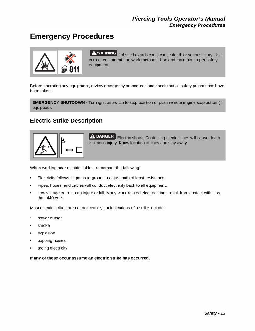
Emergency Procedures
Before operating any equipment, review emergency procedures and check that all safety precautions have been taken.
Electric Strike Description
When working near electric cables, remember the following:
• Electricity follows all paths to ground, not just path of least resistance.
• Pipes, hoses, and cables will conduct electricity back to all equipment.
• Low voltage current can injure or kill. Many work-related electrocutions result from contact with less than 440 volts.
Most electric strikes are not noticeable, but indications of a strike include:
• power outage
• smoke
• explosion
• popping noises
• arcing electricity
If any of these occur assume an electric strike has occurred.
Jobsite hazards could cause death or serious injury. Use correct equipment and work methods. Use and maintain proper safety equipment.
EMERGENCY SHUTDOWN - Turn ignition switch to stop position or push remote engine stop button (if equipped).
Electric shock. Contacting electric lines will cause death or serious injury. Know location of lines and stay away.
Safety - 13

Piercing Tools Operator’s ManualEmergency Procedures
If an Electric Line is Damaged
If you suspect an electric line has been damaged and you are in pit, DO NOT MOVE and DO NOT TOUCH ANYTHING. Remain in pit and take the following actions. The order and degree of action will depend upon the situation.
• Warn people nearby that an electric strike has occurred. Instruct them to leave the area and contact utility.
• Contact utility company to shut off power.
• Do not leave pit until given permission by utility company.
If you suspect an electric line has been damaged and you are out of pit, DO NOT TOUCH ANYTHING. Take the following actions. The order and degree of action will depend upon the situation.
• LEAVE AREA. The ground surface may be electrified, so take small steps with feet close together to reduce the hazard of being shocked from one foot to the other.
• Contact utility company to shut off power.
• Do not return to jobsite or allow anyone into area until given permission by utility company.
If you suspect an electric line has been damaged and you are on other piece of equipment, DO NOT MOVE. Remain on truck or trailer and take the following actions. The order and degree of action will depend upon the situation.
• Warn people nearby that an electric strike has occurred. Instruct them to leave the area and contact utility.
• Contact utility company to shut off power.
• Do not return to area or allow anyone into are until given permission by utility company.
14 - Safety
Piercing Tools Operator’s ManualEmergency Procedures
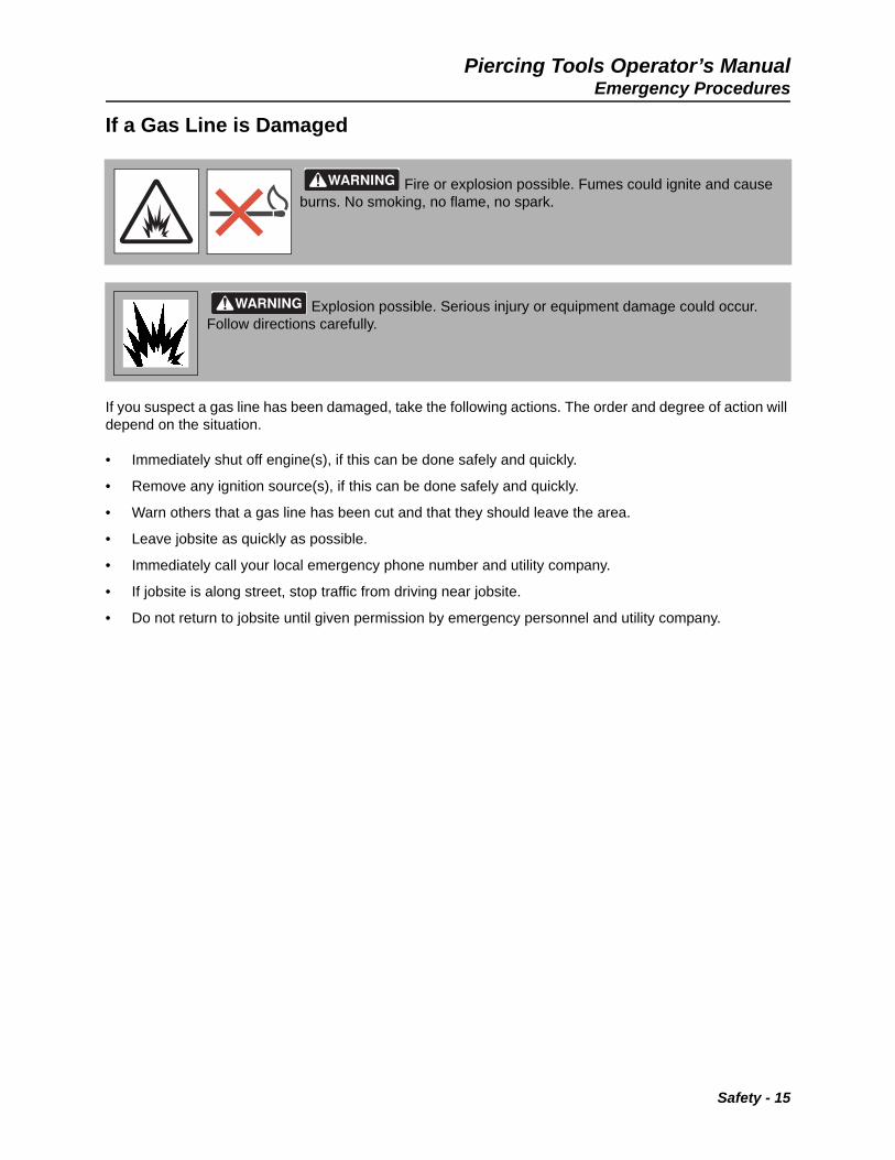
If a Gas Line is Damaged
If you suspect a gas line has been damaged, take the following actions. The order and degree of action will depend on the situation.
• Immediately shut off engine(s), if this can be done safely and quickly.
• Remove any ignition source(s), if this can be done safely and quickly.
• Warn others that a gas line has been cut and that they should leave the area.
• Leave jobsite as quickly as possible.
• Immediately call your local emergency phone number and utility company.
• If jobsite is along street, stop traffic from driving near jobsite.
• Do not return to jobsite until given permission by emergency personnel and utility company.
Fire or explosion possible. Fumes could ignite and cause burns. No smoking, no flame, no spark.
Explosion possible. Serious injury or equipment damage could occur. Follow directions carefully.
Safety - 15
Piercing Tools Operator’s ManualEmergency Procedures
If a Fiber Optic Cable is Damaged
Do not look into cut ends of fiber optic or unidentified cable. Vision damage can occur. Contact utility company.
If Machine Catches on Fire
Perform emergency shutdown procedure and then take the following actions. The order and degree of action will depend on the situation.
• Immediately move battery disconnect switch (if equipped and accessible) to disconnect position.
• If fire is small and fire extinguisher is available, attempt to extinguish fire.
• If fire cannot be extinguished, leave area as quickly as possible and contact emergency personnel.
16 - Safety
Piercing Tools Operator’s ManualSafety Alert Classifications
Safety Alert Classifications
These classifications and the icons defined on the following pages work together to alert you to situations which could be harmful to you, jobsite bystanders or your equipment. When you see these words and icons in the book or on the machine, carefully read and follow all instructions. YOUR SAFETY IS AT STAKE.
Watch for the three safety alert levels: DANGER, WARNING and CAUTION. Learn what each level means.
indicates a hazardous situation that, if not avoided, will result in death or serious injury. This signal word is to be limited to the most extreme situations.
indicates a hazardous situation that, if not avoided, could result in death or serious injury.
indicates a hazardous situation that, if not avoided, could result in minor or moderate injury.
Watch for two other words: NOTICE and IMPORTANT.
NOTICE indicates information considered important, but not hazard-related (e.g., messages relating to property damage).
IMPORTANT can help you do a better job or make your job easier in some way.
Safety - 17
Piercing Tools Operator’s ManualMachine Safety Alerts
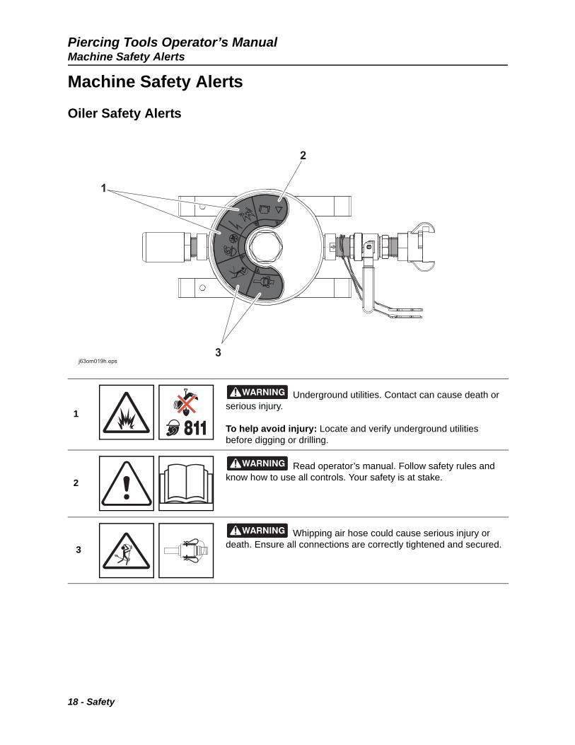
Machine Safety Alerts
Oiler Safety Alerts
1
Underground utilities. Contact can cause death or serious injury.
To help avoid injury: Locate and verify underground utilities before digging or drilling.
2
Read operator’s manual. Follow safety rules and know how to use all controls. Your safety is at stake.
3
Whipping air hose could cause serious injury or death. Ensure all connections are correctly tightened and secured.
18 - Safety
Piercing Tools Operator’s ManualMachine Safety Alerts
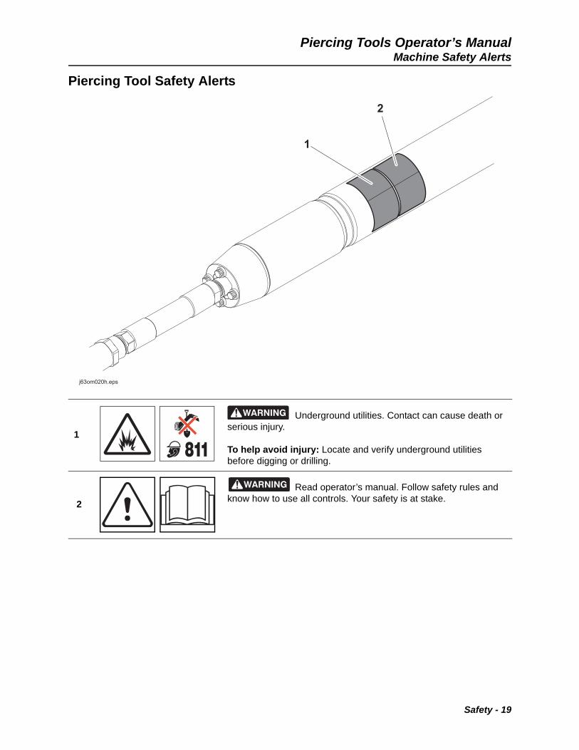
Piercing Tool Safety Alerts
1
Underground utilities. Contact can cause death or serious injury.
To help avoid injury: Locate and verify underground utilities before digging or drilling.
2
Read operator’s manual. Follow safety rules and know how to use all controls. Your safety is at stake.
Safety - 19

Piercing Tools Operator’s ManualMachine Safety Alerts
20 - Safety
Piercing Tools Operator’s Manual
Controls
Chapter Contents
Oiler . . . . . . . . . . . . . . . . . . . . . . . . . . . . . . . . . . . . . 22
Rear Whip . . . . . . . . . . . . . . . . . . . . . . . . . . . . . . . . 23
Launch Platform . . . . . . . . . . . . . . . . . . . . . . . . . . . 24
Shoring Kit. . . . . . . . . . . . . . . . . . . . . . . . . . . . . . . . 26
Controls - 21
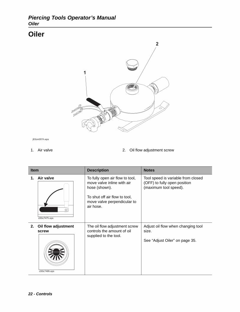
Piercing Tools Operator’s ManualOiler
Oiler
1. Air valve 2. Oil flow adjustment screw
Item Description Notes
1. Air valve To fully open air flow to tool, move valve inline with air hose (shown).
To shut off air flow to tool, move valve perpendicular to air hose.
Tool speed is variable from closed (OFF) to fully open position (maximum tool speed).
2. Oil flow adjustment screw
The oil flow adjustment screw controls the amount of oil supplied to the tool.
Adjust oil flow when changing tool size.
See “Adjust Oiler” on page 35.
11
22
j63om001h.epsj63om001h.eps
c00ic747h.eps
c00ic748h.eps
22 - Controls
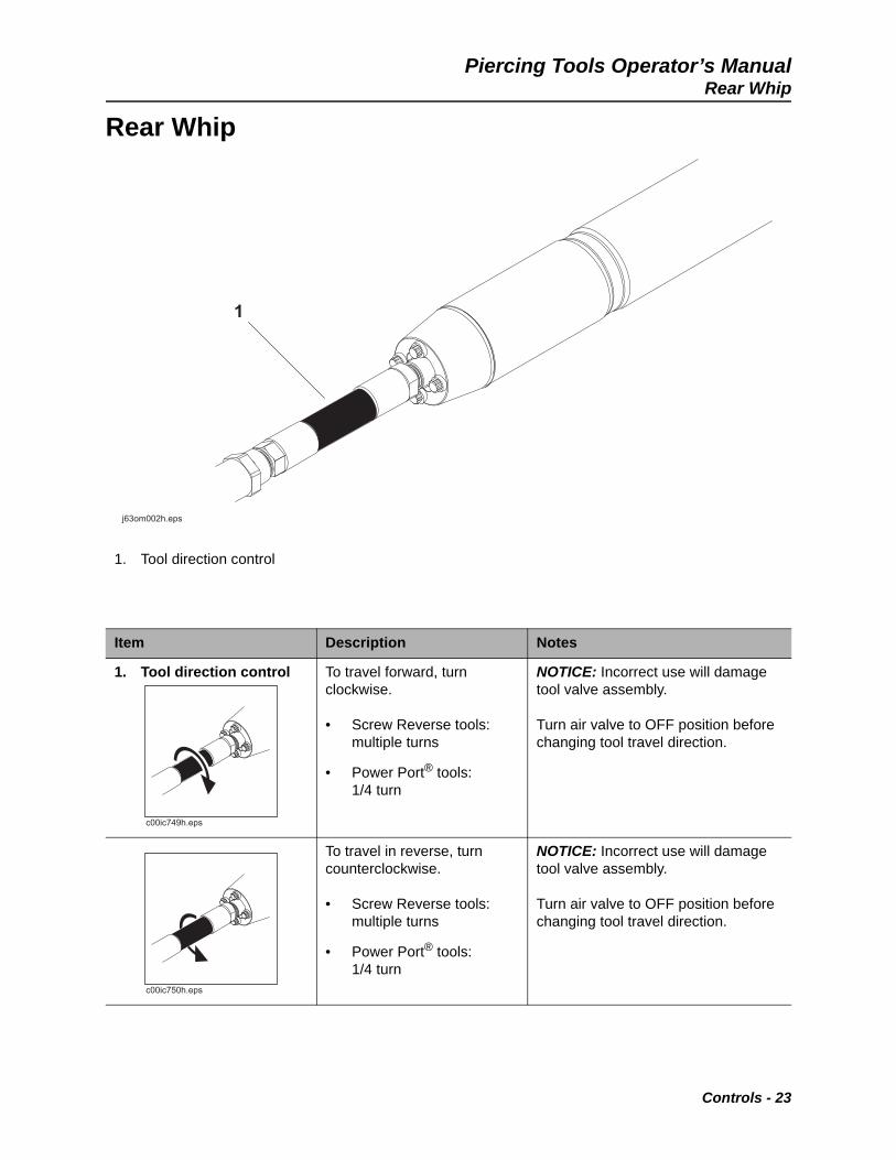
Piercing Tools Operator’s ManualRear Whip
Rear Whip
1. Tool direction control
Item Description Notes
1. Tool direction control To travel forward, turn clockwise.
• Screw Reverse tools: multiple turns
• Power Port® tools: 1/4 turn
NOTICE: Incorrect use will damage tool valve assembly.
Turn air valve to OFF position before changing tool travel direction.
To travel in reverse, turn counterclockwise.
• Screw Reverse tools: multiple turns
• Power Port® tools: 1/4 turn
NOTICE: Incorrect use will damage tool valve assembly.
Turn air valve to OFF position before changing tool travel direction.
11
j63om002h.epsj63om002h.eps
c00ic749h.eps
c00ic750h.eps
Controls - 23
Piercing Tools Operator’s ManualLaunch Platform
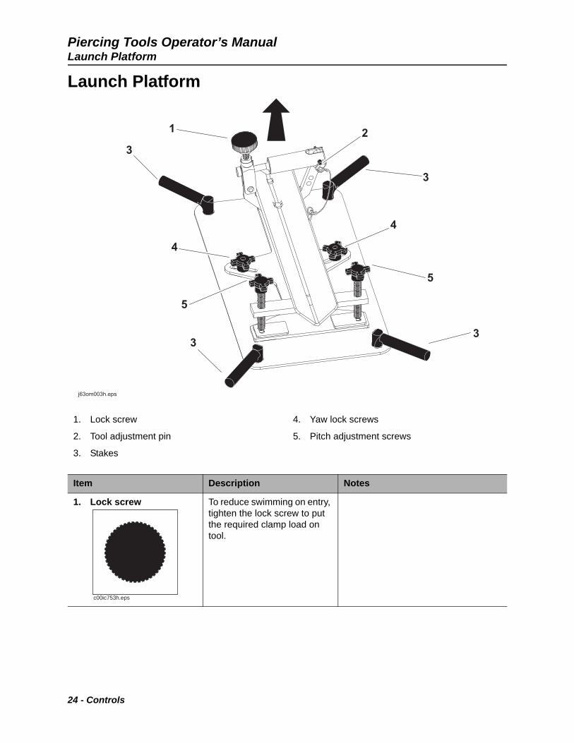
Launch Platform
1. Lock screw
2. Tool adjustment pin
3. Stakes
4. Yaw lock screws
5. Pitch adjustment screws
Item Description Notes
1. Lock screw To reduce swimming on entry, tighten the lock screw to put the required clamp load on tool.
11
44
44
55
55
33
22
33
3333
j63om003h.epsj63om003h.eps
c00ic753h.eps
24 - Controls

Piercing Tools Operator’s ManualLaunch Platform
2. Tool adjustment pin To select tool size, adjust tool adjustment pin.
3. Stakes To secure launch platform, put stakes in ground.
4. Yaw lock screws To set the yaw of the tool, adjust yaw lock screws.
5. Pitch adjustment screws
To adjust the pitch of the tool, adjust pitch adjustment screws.
Item Description Notes
c00ic752h.eps
Controls - 25

Piercing Tools Operator’s ManualShoring Kit
Shoring Kit
1. Pins
2. Adjustment screws
3. Locking handle
4. Release button
Item Description Notes
1. Pins To secure shoring kit to launch platform, use pins.
26 - Controls

Piercing Tools Operator’s ManualShoring Kit
2. Adjustment screw To adjust and set length of shoring kit, turn adjustment screw.
3. Locking handle To lock shoring kit adjustment screws once they are in correct position, pump locking handle.
4. Release button To unlock screws to disassemble shoring kit when job is completed, push release button.
Item Description Notes
Controls - 27

Piercing Tools Operator’s ManualShoring Kit
28 - Controls

Piercing Tools Operator’s Manual
Prepare
Chapter Contents
Gather Information . . . . . . . . . . . . . . . . . . . . . . . . . 30
• Review Job Plan . . . . . . . . . . . . . . . . . . . . . . . . . . . . . . . . . . . . . . . . . . .30
• Notify One-Call Services . . . . . . . . . . . . . . . . . . . . . . . . . . . . . . . . . . . . .30
• Examine Pullback Material . . . . . . . . . . . . . . . . . . . . . . . . . . . . . . . . . . .30
• Arrange for Traffic Control. . . . . . . . . . . . . . . . . . . . . . . . . . . . . . . . . . . .30
• Plan for Emergency Services . . . . . . . . . . . . . . . . . . . . . . . . . . . . . . . . .30
Inspect Site . . . . . . . . . . . . . . . . . . . . . . . . . . . . . . . 31
Identify Hazards . . . . . . . . . . . . . . . . . . . . . . . . . . . 32
Prepare Jobsite . . . . . . . . . . . . . . . . . . . . . . . . . . . . 33
• Mark Jobsite . . . . . . . . . . . . . . . . . . . . . . . . . . . . . . . . . . . . . . . . . . . . . .33
• Dig Entry and Exit Pits . . . . . . . . . . . . . . . . . . . . . . . . . . . . . . . . . . . . . .33
• Clear Work Area . . . . . . . . . . . . . . . . . . . . . . . . . . . . . . . . . . . . . . . . . . .33
Prepare Equipment . . . . . . . . . . . . . . . . . . . . . . . . . 34
• Prepare Air Compressor . . . . . . . . . . . . . . . . . . . . . . . . . . . . . . . . . . . . .34
• Assemble Equipment . . . . . . . . . . . . . . . . . . . . . . . . . . . . . . . . . . . . . . .34
• Adjust Oiler . . . . . . . . . . . . . . . . . . . . . . . . . . . . . . . . . . . . . . . . . . . . . . .35
• Check Oiler Oil Level . . . . . . . . . . . . . . . . . . . . . . . . . . . . . . . . . . . . . . .36
• Adjust Tool Pitch and Yaw. . . . . . . . . . . . . . . . . . . . . . . . . . . . . . . . . . . .36
Prepare - 29

Piercing Tools Operator’s ManualGather Information
Gather Information
A successful job begins before the bore. The first step in planning is reviewing information already available about the job and jobsite.
Review Job Plan
Review blueprints or other plans. Check for information about existing or planned structures, elevations, or proposed work that may be taking place at the same time.
Notify One-Call Services
Mark proposed path with white paint and have underground utilities located before working.
• In the US or Canada, call 811 (US) or 888-258-0808 (US and Canada). Also contact any local utilities that do not participate in the One-Call service.
• In countries that do not have a One-Call service, contact all local utility companies to have underground utilities located.
Examine Product Material
Ask for a sample of the new product material you will be installing. Check its weight and stiffness. Contact the manufacturer for bend radius information.
Arrange for Traffic Control
If working near a road or other traffic area, contact local authorities about safety procedures and regulations.
Plan for Emergency Services
Have the telephone numbers for local emergency and medical facilities on hand. Check that you will have access to a telephone.
If required, mount a fire extinguisher near the compressor but away from possible points of ignition. The fire extinguisher should always be classified for both oil and electric fires. It should meet legal and regulatory requirements.
30 - Prepare

Piercing Tools Operator’s ManualInspect Site
Inspect Site
Inspect jobsite before transporting equipment. Check for the following:
• changes in elevation such as hills or open trenches
• obstacles such as buildings, railroad crossings, or streams
• signs of utilities
– “buried utility” notices
– utility facilities without overhead lines
– gas or water meters
– junction boxes
– drop boxes
– light poles
– manhole covers
– sunken ground
• traffic
• access
• soil type and condition
• depths of existing pipes
Prepare - 31

Piercing Tools Operator’s ManualIdentify Hazards
Identify Hazards
• Identify safety hazards. Follow U.S. Department of Labor regulations on excavating and trenching (Part 1926, Subpart P) and other similar regulations.
• Have an experienced locating equipment operator sweep area within 20’ (6 m) to each side of bore path. Verify previously marked line and cable locations.
• Mark location of all buried utilities and obstructions.
Underground utilities. Contact can cause death or serious injury.
To help avoid injury:
• Wear personal protective equipment including hard hat, safety eye wear, and hearing protection.
• Do not wear jewelry or loose clothing.
• Notify One-Call and companies which do not subscribe to One-Call.
• Comply with all utility notification regulations before digging or launching.
• Locate and verify underground utilities before digging or drilling.
• Mark jobsite clearly and keep spectators away.
32 - Prepare

Piercing Tools Operator’s ManualPrepare Jobsite
Prepare Jobsite
Mark Jobsite
Mark jobsite with flags or paint:
• planned bore path
• entry and exit pits
Dig Entry and Exit Pits
Dig pits that meet the following conditions:
• Length and width of the pits are long enough to keep supply line from kinking during launch.
• Recommended depth is approximately 10 times the diameter of the tool.
• The maximum distance between the entry and exit pits is 50 ft (15 m).
Clear Work Area
• Clear work area of all objects that could interfere with proper operation of the tool or hoses.
• Do not leave tools and other objects near the entry and exit pits.
NOTICE: Follow U.S. Department of Labor regulations on excavating and trenching (Part 1926, Subpart P) and other similar regulations.
Prepare - 33

Piercing Tools Operator’s ManualPrepare Equipment
Prepare Equipment
Prepare Air Compressor
1. Park air compressor a sufficient distance from entry pit to prevent pit cave-in.
2. Chock wheels.
3. Set air pressure to the appropriate level.
Assemble Equipment
1. Connect oiler supply hose:
• to compressor
• to oiler (1)
2. Assemble piercing tool supply hoses of sufficient length and connect:
• to oiler (1)
• to piercing tool (3)
NOTICE: Incorrect air pressure setting will damage tool and void the warranty. Do not set air pressure at tool above 110 psi (7.6 bar).
IMPORTANT: When operating the tool for the first time, add 0.5 oz (15 ml) of oil directly into rear whip (2) before connecting supply hose.
34 - Prepare

Piercing Tools Operator’s ManualPrepare Equipment
Adjust Oiler
The adjustment screw has hash marks that represent 1/16 of a turn.
1. Turn air valve to the OFF position.
2. Remove fill plug (1).
3. Use slotted screwdriver to turn adjustment screw (2) fully clockwise to closed position.
4. Use chart to select setting applicable to piercing tool size.
5. Turn adjustment screw (2) counterclockwise to correct position.
NOTICE: Incorrect oil flow setting can reduce tool performance. Ensure oil flow setting is applicable to the tool size.
Tool Size Number of hash marks counterclockwise from closed position
in mm
2 45 16
2-1/2 63 14
3 75 14
3-1/2 89 14
4 98 8
4-3/8 111 8
5-1/8 130 6
5-3/4 146 4
IMPORTANT: Up to 30 minutes may be necessary for oiler adjustment to be noticeable in tool operation.
Prepare - 35
Piercing Tools Operator’s ManualPrepare Equipment
Check Oiler Oil Level
See “Check Oiler Oil Level” on page 51.
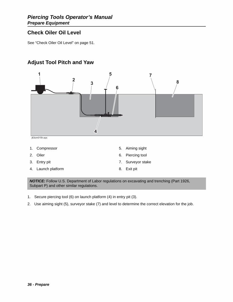
Adjust Tool Pitch and Yaw
1. Secure piercing tool (6) on launch platform (4) in entry pit (3).
2. Use aiming sight (5), surveyor stake (7) and level to determine the correct elevation for the job.
1. Compressor
2. Oiler
3. Entry pit
4. Launch platform
5. Aiming sight
6. Piercing tool
7. Surveyor stake
8. Exit pit
NOTICE: Follow U.S. Department of Labor regulations on excavating and trenching (Part 1926, Subpart P) and other similar regulations.
36 - Prepare
Piercing Tools Operator’s ManualPrepare Equipment
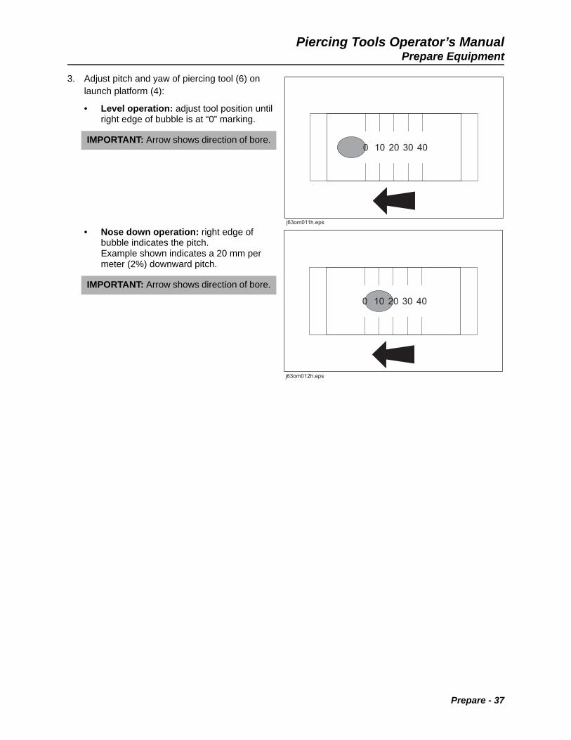
3. Adjust pitch and yaw of piercing tool (6) on launch platform (4):
• Level operation: adjust tool position until right edge of bubble is at “0” marking.
• Nose down operation: right edge of bubble indicates the pitch. Example shown indicates a 20 mm per meter (2%) downward pitch.
IMPORTANT: Arrow shows direction of bore.
IMPORTANT: Arrow shows direction of bore.
Prepare - 37

Piercing Tools Operator’s ManualPrepare Equipment
38 - Prepare
Piercing Tools Operator’s Manual
Operate
Chapter Contents
Bore . . . . . . . . . . . . . . . . . . . . . . . . . . . . . . . . . . . . . 40
• Standard Bore . . . . . . . . . . . . . . . . . . . . . . . . . . . . . . . . . . . . . . . . . . . . .40
• Stitch Bore. . . . . . . . . . . . . . . . . . . . . . . . . . . . . . . . . . . . . . . . . . . . . . . .40
Reverse Tool Direction . . . . . . . . . . . . . . . . . . . . . . 41
Shut Down and Disassemble Equipment . . . . . . . 41
Troubleshooting . . . . . . . . . . . . . . . . . . . . . . . . . . . 42
Operate - 39

Piercing Tools Operator’s ManualBore
Bore
Standard Bore
Two persons are required to operate the tool:
• One person to control the air supply to the tool
• One person to monitor the tool and the supply hose
To start bore:
1. Start compressor.
2. Quickly open air valve.
3. Change air supply to adjust tool speed as necessary. Average production is 1 ft/min (305 mm/min).
Stitch Bore
In order to complete longer bores, dig multiple pits 30-50 ft (9-15 m) apart along the bore path. Use tool to pierce hole from pit to pit. Shut down, disconnect and reposition equipment at the end of each bore.
Pressurized fluid or air. Injection can cause death or serious injury.
To help avoid injury:
• Ensure couplings are tight and secured with the applicable retaining devices.
• Check air supply hose and fittings for wear and tear.
• Shut down unit immediately at the first sign of malfunction or hazardous situation.
Thrown objects. Impact can cause injury.
To help avoid injury:
• Wear hard hat and safety glasses.
• Stay away from high-pressure exhaust.
• Stay away from the bore hole during operation.
40 - Operate
Piercing Tools Operator’s ManualReverse Tool Direction
Reverse Tool Direction
1. Turn air valve to OFF position and wait fro pressure to release.
2. Turn air supply hose fully counterclockwise to reverse tool direction:
• Screw Reverse tools: Turn multiple turns.
• Power Port® tools: Turn 1/4 turn.
3. Quickly open air valve. Change air supply to adjust tool speed as necessary.
4. Pull hose to prevent backing over.
Shut Down and Disassemble Equipment
1. Turn air valve to OFF position.
2. Shut down air compressor.
3. Disconnect hoses.
4. Install cap at end of rear whip or apply tape to prevent dirt from entering tool.
NOTICE: Incorrect use will damage tool valve assembly. Turn air valve to OFF position before changing tool travel direction.
IMPORTANT: It may be necessary to disconnect air supply hose from oiler.
IMPORTANT: It may be necessary to turn air supply hose one full turn for rear whip to turn 1/4 turn.
Pressurized fluid or air. Injection can cause death or serious injury.
To help avoid injury:
• Turn air valve to OFF position to release pressure after each use.
• Wait for pressure to be released before disconnecting hoses.
Operate - 41
Piercing Tools Operator’s ManualTroubleshooting
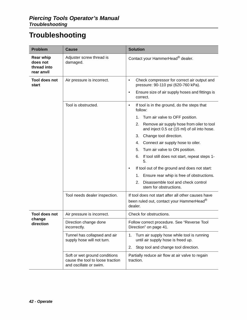
Troubleshooting
Problem Cause Solution
Rear whip does not thread into rear anvil
Adjuster screw thread is damaged.
Contact your HammerHead® dealer.
Tool does not start
Air pressure is incorrect. • Check compressor for correct air output and pressure: 90-110 psi (620-760 kPa).
• Ensure size of air supply hoses and fittings is correct.
Tool is obstructed. • If tool is in the ground, do the steps that follow:
1. Turn air valve to OFF position.
2. Remove air supply hose from oiler to tool and inject 0.5 oz (15 ml) of oil into hose.
3. Change tool direction.
4. Connect air supply hose to oiler.
5. Turn air valve to ON position.
6. If tool still does not start, repeat steps 1-5.
• If tool out of the ground and does not start:
1. Ensure rear whip is free of obstructions.
2. Disassemble tool and check control stem for obstructions.
Tool needs dealer inspection. If tool does not start after all other causes have
been ruled out, contact your HammerHead® dealer.
Tool does not change direction
Air pressure is incorrect. Check for obstructions.
Direction change done incorrectly.
Follow correct procedure. See “Reverse Tool Direction” on page 41.
Tunnel has collapsed and air supply hose will not turn.
1. Turn air supply hose while tool is running until air supply hose is freed up.
2. Stop tool and change tool direction.
Soft or wet ground conditions cause the tool to loose traction and oscillate or swim.
Partially reduce air flow at air valve to regain traction.
42 - Operate

Piercing Tools Operator’s ManualTroubleshooting
Tool runs but does not move in hole
Whip hose is not in FORWARD position.
Ensure rear whip is in FORWARD position.
Soft or wet ground conditions cause the tool to loose traction and oscillate or swim.
Partially reduce air flow at air valve to regain traction.
Tool is obstructed. 1. Change tool direction.
2. Start new bore at least 10 times the diameter of the tool away from current bore.
Tool cycles fast and seems low on power
Valve assembly is too short. Check length of valve assembly.
Soft or wet ground conditions cause the tool to loose traction and oscillate or swim.
Partially reduce air flow at air valve to regain traction.
Tool slows down during long bores
Striker is contaminated with dirt. Test striker friction:
• Put tool in horizontal position.
• Slowly tip tool rearward. The striker should slide from front to back when tool is at a 22° angle.
• If a larger angle is necessary for striker to slide, disassemble and clean tool.
Tunnel has collapsed on air supply hose and air flow is restricted.
Turn air supply hose while tool is running until air supply hose is freed up.
Problem Cause Solution
Operate - 43
Piercing Tools Operator’s ManualTroubleshooting
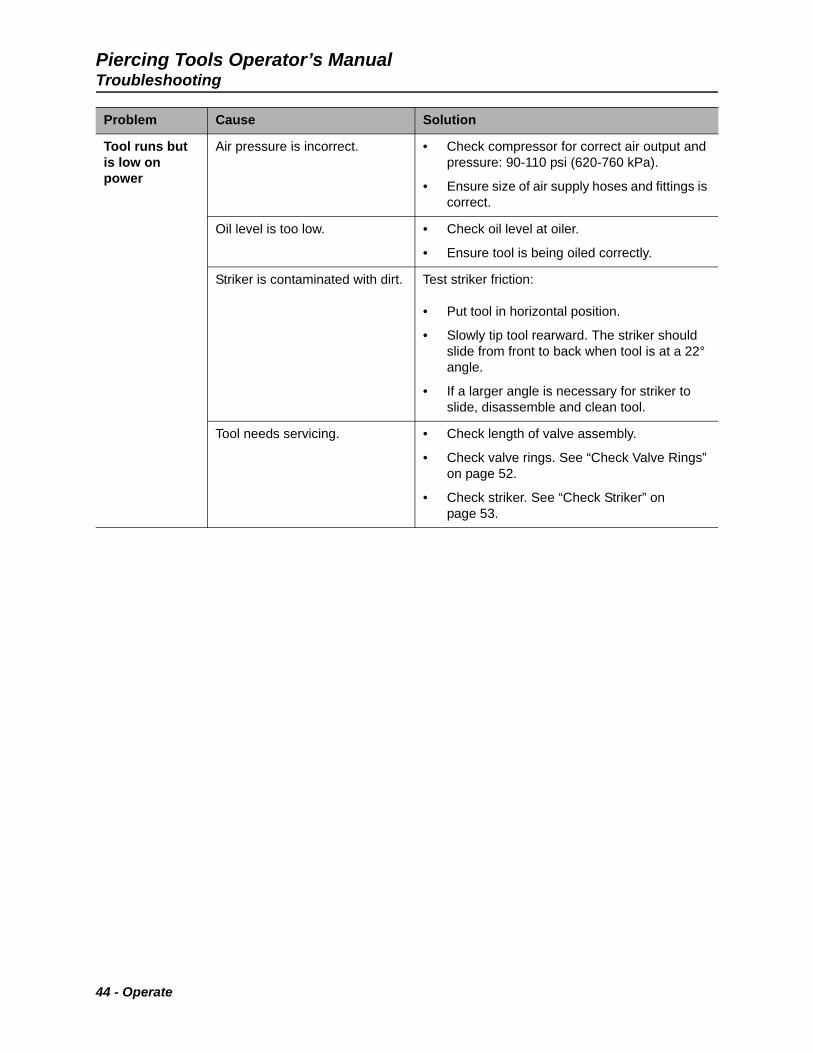
Tool runs but is low on power
Air pressure is incorrect. • Check compressor for correct air output and pressure: 90-110 psi (620-760 kPa).
• Ensure size of air supply hoses and fittings is correct.
Oil level is too low. • Check oil level at oiler.
• Ensure tool is being oiled correctly.
Striker is contaminated with dirt. Test striker friction:
• Put tool in horizontal position.
• Slowly tip tool rearward. The striker should slide from front to back when tool is at a 22° angle.
• If a larger angle is necessary for striker to slide, disassemble and clean tool.
Tool needs servicing. • Check length of valve assembly.
• Check valve rings. See “Check Valve Rings” on page 52.
• Check striker. See “Check Striker” on page 53.
Problem Cause Solution
44 - Operate

Piercing Tools Operator’s Manual
Systems and Equipment
Chapter Contents
Accessories. . . . . . . . . . . . . . . . . . . . . . . . . . . . . . . 46
Systems and Equipment - 45

Piercing Tools Operator’s ManualAccessories
Accessories
For piercing tool accessories see HammerHead® accessories catalog.
46 - Systems and Equipment
Piercing Tools Operator’s Manual
Service
Chapter Contents
Service Precautions . . . . . . . . . . . . . . . . . . . . . . . . 48
Recommended Lubricants/Service Key . . . . . . . . 48
Disassemble . . . . . . . . . . . . . . . . . . . . . . . . . . . . . . 49
Each Use . . . . . . . . . . . . . . . . . . . . . . . . . . . . . . . . . 51
120 Hours. . . . . . . . . . . . . . . . . . . . . . . . . . . . . . . . . 52
200 Hours. . . . . . . . . . . . . . . . . . . . . . . . . . . . . . . . . 53
As Needed . . . . . . . . . . . . . . . . . . . . . . . . . . . . . . . . 57
Service - 47

Piercing Tools Operator’s ManualService Precautions
Service Precautions
Recommended Lubricants/Service Key
Proper lubrication and maintenance protects HammerHead equipment from damage and failure. Service intervals listed are minimum requirements. In extreme conditions, service machine more frequently.
• Use only recommended fluids.
• Use only genuine HammerHead parts and approved fluids to maintain warranty.
• Obey applicable laws and regulations to dispose of used fluids.
Read operator’s manual. Know how to use all controls. Your safety is at stake.
To help avoid injury: Turn air valve to OFF position and disconnect the air line before servicing the tool.
NOTICE: Heat can damage tool. Do not use a torch or a welder on the tool.
Item Description
HMO HammerHead Mole® OilThis specially formulated lubricant is the preferred choice for all HammerHead piercing tools, delivering performance and reliability during most weather conditions.
HMBO Bio/Winter OilThis specially formulated, biodegradable oil is an excellent choice for all HammerHead piercing tools for all seasons and provides superior anti-wear and extreme pressure protection. Environmentally friendly, this lubricant is also suitable for cold weather operation in temperatures as low as -25°F (-32°C).
Check level of fluid or lubricant
Check condition
Replace
IMPORTANT: Use the “Service Record” on page 63 to record all required service to your machine.
48 - Service
Piercing Tools Operator’s ManualDisassemble
Disassemble
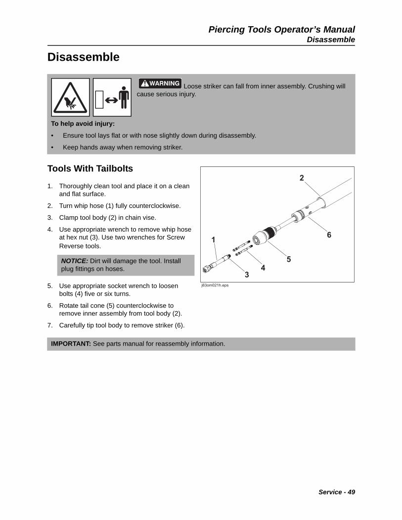
Tools With Tailbolts
1. Thoroughly clean tool and place it on a clean and flat surface.
2. Turn whip hose (1) fully counterclockwise.
3. Clamp tool body (2) in chain vise.
4. Use appropriate wrench to remove whip hose at hex nut (3). Use two wrenches for Screw Reverse tools.
5. Use appropriate socket wrench to loosen bolts (4) five or six turns.
6. Rotate tail cone (5) counterclockwise to remove inner assembly from tool body (2).
7. Carefully tip tool body to remove striker (6).
Loose striker can fall from inner assembly. Crushing will cause serious injury.
To help avoid injury:
• Ensure tool lays flat or with nose slightly down during disassembly.
• Keep hands away when removing striker.
NOTICE: Dirt will damage the tool. Install plug fittings on hoses.
IMPORTANT: See parts manual for reassembly information.
Service - 49

Piercing Tools Operator’s ManualDisassemble
Tools Without Tailbolts
1. Thoroughly clean tool and place it on a clean and flat surface.
2. Turn whip hose (1) fully counterclockwise.
3. Clamp tool body (2) in chain vise.
4. Use appropriate wrench to remove whip hose.
5. Use appropriate socket to loosen and remove tailcone (4).
6. Rotate rear anvil (5) counterclockwise to remove inner assembly from tool body (2).
7. Carefully tip tool body to remove striker (6).
NOTICE: Dirt will damage the tool. Install plug fittings on hoses.
IMPORTANT: See parts manual for reassembly information.
50 - Service
Piercing Tools Operator’s ManualEach Use
Each Use
Check Hose Fittings and Connections
Check hose fittings and connections before each use.
1. Turn air valve to OFF position.
2. Check hose fittings and connections.
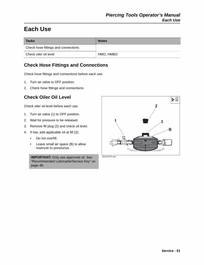
Check Oiler Oil Level
Check oiler oil level before each use.
1. Turn air valve (1) to OFF position.
2. Wait for pressure to be released.
3. Remove fill plug (2) and check oil level.
4. If low, add applicable oil at fill (3):
• Do not overfill.
• Leave small air space (B) to allow reservoir to pressurize.
Tasks Notes
Check hose fittings and connections
Check oiler oil level HMO, HMBO
IMPORTANT: Only use approved oil. See “Recommended Lubricants/Service Key” on page 48.
Service - 51
Piercing Tools Operator’s Manual120 Hours
120 Hours
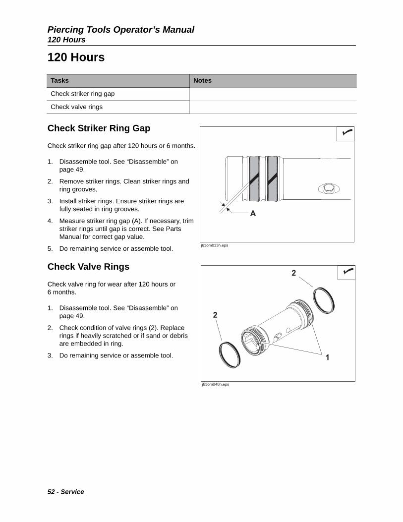
Check Striker Ring Gap
Check striker ring gap after 120 hours or 6 months.
1. Disassemble tool. See “Disassemble” on page 49.
2. Remove striker rings. Clean striker rings and ring grooves.
3. Install striker rings. Ensure striker rings are fully seated in ring grooves.
4. Measure striker ring gap (A). If necessary, trim striker rings until gap is correct. See Parts Manual for correct gap value.
5. Do remaining service or assemble tool.
Check Valve Rings
Check valve ring for wear after 120 hours or 6 months.
1. Disassemble tool. See “Disassemble” on page 49.
2. Check condition of valve rings (2). Replace rings if heavily scratched or if sand or debris are embedded in ring.
3. Do remaining service or assemble tool.
Tasks Notes
Check striker ring gap
Check valve rings
52 - Service

Piercing Tools Operator’s Manual200 Hours
200 Hours
Check Striker
Check striker every 200 hours or 12 months.
1. Check front and rear impact surfaces of striker. If more than 50% of either surface is heavily chipped or cracked, replace striker.
2. For Catamount tools only, use flashlight to check striker inside surfaces for debris. Clean if necessary.
3. Check striker rings for wear. If there is no gap (A), replace striker ring.
4. Check gap on striker rings. See “Check Striker Ring Gap” on page 52.
Tasks Notes
Check striker
Check valve
Check control stem and isolator Power Port® tools
Check internal whip and rear anvil Screw Reverse tools
NOTICE: Steel to steel contact will increase wear. Replace worn striker rings immediately.
Service - 53
Piercing Tools Operator’s Manual200 Hours
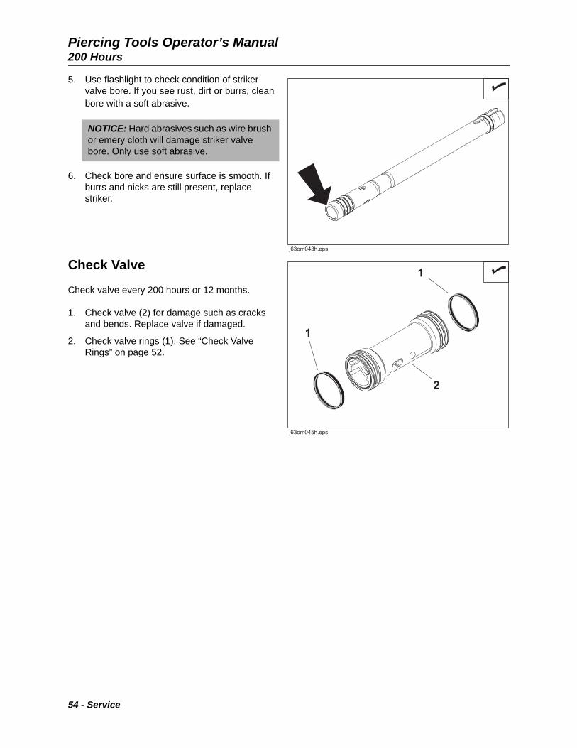
5. Use flashlight to check condition of striker valve bore. If you see rust, dirt or burrs, clean bore with a soft abrasive.
6. Check bore and ensure surface is smooth. If burrs and nicks are still present, replace striker.
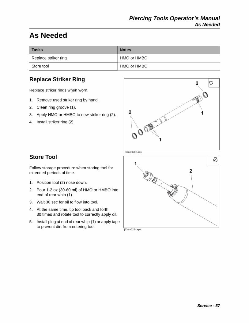
Check Valve
Check valve every 200 hours or 12 months.
1. Check valve (2) for damage such as cracks and bends. Replace valve if damaged.
2. Check valve rings (1). See “Check Valve Rings” on page 52.
NOTICE: Hard abrasives such as wire brush or emery cloth will damage striker valve bore. Only use soft abrasive.
54 - Service

Piercing Tools Operator’s Manual200 Hours
Check Control Stem and Isolator (Power Port® Tools)
Check control stem and isolator every 200 hours or 12 months.
1. Remove control stud (6).
2. Remove valve (5).
3. Remove control sleeve (4). Check control sleeve for nicks, cuts, tears or other damage. Replace if damaged.
4. Remove rear anvil (3). Check surface that contacts with striker. If more than 50% of surface is heavily chipped or cracked, replace anvil.
5. Use approved air nozzle to thoroughly clean air ports and bores of rear anvil (3).
6. Remove isolator halves (1). Check inside grooves for damage. Replace if damaged.
7. Check control stem (2) for worn out threads, bends, or any other damage. Replace if damaged.
8. Compress control sleeve (4) until valve seats on valve taper and check compressed valve length (A). If value is outside range given in parts manual, replace control stem.
AA
j63om038h.epsj63om038h.eps
Service - 55

Piercing Tools Operator’s Manual200 Hours
Check Internal Whip and Rear Anvil (Screw Reverse Tools)
Check internal whip and rear anvil every 200 hours or 12 months.
1. Remove internal whip and check threads (1) and bore (2). Threads must be flat on top. If threads are sharp, replace internal whip.
2. Check surface of rear anvil (3) that impacts with striker. If more than 50% of surface is heavily chipped or cracked, replace anvil.
3. Use approved air nozzle to thoroughly clean air ports and bores of rear anvil (3).
4. Check threads of rear anvil (3). Threads must be flat on top. If threads are sharp, replace rear anvil.
5. Turn internal whip fully clockwise and check internal valve length (A). If value is outside range given in parts manual, replace internal whip.
11
22
33
j63om048h.epsj63om048h.eps
AA
j63om039h.epsj63om039h.eps
56 - Service
Piercing Tools Operator’s ManualAs Needed
As Needed
Replace Striker Ring
Replace striker rings when worn.
1. Remove used striker ring by hand.
2. Clean ring groove (1).
3. Apply HMO or HMBO to new striker ring (2).
4. Install striker ring (2).
Store Tool
Follow storage procedure when storing tool for extended periods of time.
1. Position tool (2) nose down.
2. Pour 1-2 oz (30-60 ml) of HMO or HMBO into end of rear whip (1).
3. Wait 30 sec for oil to flow into tool.
4. At the same time, tip tool back and forth 30 times and rotate tool to correctly apply oil.
5. Install plug at end of rear whip (1) or apply tape to prevent dirt from entering tool.
Tasks Notes
Replace striker ring HMO or HMBO
Store tool HMO or HMBO
Service - 57

Piercing Tools Operator’s ManualAs Needed
58 - Service

Piercing Tools Operator’s Manual
Specifications
Please go to www.hammerheadtrenchless.com and click on Products. From there, select Piercing Tools and then the type of tool you have. Open the brochure to see the specifications for your tool.
Specifications - 59
Piercing Tools Operator’s ManualDeclaration of Conformity Information
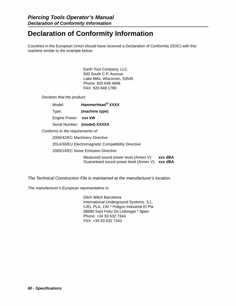
Declaration of Conformity Information
Countries in the European Union should have received a Declaration of Conformity (DOC) with this machine similar to the example below.
Earth Tool Company, LLC. 500 South C.P. AvenueLake Mills, Wisconsin, 53545Phone: 920 648 4848FAX: 920 648 1780
Declares that the product:
Model: HammerHead® XXXX
Type: (machine type)
Engine Power: xxx kW
Serial Number: (model) XXXXX
Conforms to the requirements of:
2006/42/EC Machinery Directive
2014/30/EU Electromagnetic Compatibility Directive
2000/14/EC Noise Emission Directive
Measured sound power level (Annex V): xxx dBA Guaranteed sound power level (Annex V): xxx dBA
The Technical Construction File is maintained at the manufacturer’s location.
The manufacturer’s European representative is:
Ditch Witch BarcelonaInternational Underground Systems, S.L.C/EL PLA, 130 * Poligon Industrial El Pla08980 Sant Feliu De Llobregat * SpainPhone: +34 93 632 7344FAX: +34 93 632 7343
60 - Specifications

Piercing Tools Operator’s ManualProcedure
Support
Procedure
Notify your dealer immediately of any malfunction or failure of HammerHead® equipment.
Always give model, serial number, and approximate date of your equipment purchase. This information should be recorded and placed on file by the owner at the time of purchase.
Return damaged parts to dealer for inspection and warranty consideration if in warranty time frame.
Order genuine HammerHead replacement or repair parts from your authorized HammerHead dealer. Use of another manufacturer's parts may void warranty consideration.
Resources
Publications
Contact your HammerHead dealer for publications and videos covering safety, operation, service, and repair of your equipment.
HammerHead Training
For information about on-site, individualized training, contact your HammerHead dealer.
Support - 61

Piercing Tools Operator’s ManualResources
Warranty
Two (2) Year Limited Warranty Policy
LIMITED WARRANTY. EARTH TOOL COMPANY LLC, hereinafter sometimes referred to as ETC warrants each new HammerHead® Mole 2” to 5 ¾” (50 to 145 mm) industrial of its own manufacture to be free from defects in material and workmanship, under normal use and service for two full years after delivery to the owner.
During the warranty period, the authorized selling HammerHead Dealer shall furnish parts without charge, that fail because of defects in material and workmanship. Warranty is void unless warranty registration card is returned within ten days from the date of purchase. This warranty and any possible liability of Earth Tool Company LLC hereunder is in lieu of all other warranties, express, implied, or statutory, including, but not limited to, any warranties of merchantability or fitness for a particular purpose.
The parties agree that the Buyer's SOLE AND EXCLUSIVE REMEDY against ETC, whether in contract or arising out of warranties, representations, instructions, or defects shall be for the replacement or repair of defective parts as provided herein. In no event shall ETC's liability exceed the purchase price of the product. The Buyer agrees that no other remedy (including, but not limited to, incidental or consequential loss) shall be available to him. If, during the warranty period, any product becomes defective by reason of material or workmanship and Buyer immediately notifies ETC of such defect, ETC shall, at its option, supply a replacement part or request return of the product to its plant in Lake Mills, Wisconsin.
No parts shall be returned without prior written authorization from ETC, and this Warranty does not obligate ETC to bear any transportation charges in connection with the repair or replacement of defective parts. Earth Tool Company LLC will not accept any charges for labor and/or parts incidental to the removal or remounting of parts repaired or replaced under this Warranty.
This Warranty shall not apply to any part or product which shall have been installed or operated in a manner not recommended by ETC nor to any part or product which shall have been neglected, or used in any way which, in ETC's opinion, adversely affects its performance; nor negligence of proper maintenance or other negligence, fire or other accident; nor with respect to wear items; nor if the unit has been altered or repaired outside of a ETC authorized dealership in a manner of which, in the sole judgment of ETC affects its performance, stability or reliability; nor with respect to batteries which are covered under a separate adjustment warranty; nor to any product in which parts not manufactured or approved by ETC have been used, nor to normal maintenance services or replacement of normal service items.
Equipment and accessories not of our manufacture are warranted only to the extent of the original Manufacturer's Warranty and subject to their allowance to us, if found defective by them. ETC reserves the right to modify, alter, and improve any product or parts without incurring any obligation to replace any product or parts previously sold with such modified, altered, or improved product or part. No person is authorized to give any other Warranty, or to assume any additional obligation on ETC's behalf unless made in writing, and signed by an officer of ETC.
EARTH TOOL COMPANY LLC
Lake Mills, Wisconsin
62 - Warranty

Piercing Tools Operator’s Manual
Service Record
Service Performed Date Hours
Service Record - 63

Piercing Tools Operator’s Manual
Service Performed Date Hours
64 - Service Record