Technical Report on the Stratoni Project Pb Zn Ag Deposit, Northern Greece European Goldfields Limited Suite 200, Financial Plaza 204 Lambert Street Whitehorse, Yukon Canada Y1A 3T2 Patrick Forward September 21 st , 2010 Vice President, Projects and Exploration, MAusIMM Antony Francis Senior Group Metallurgist, FIMMM Niel Liddell, MIMMM Senior Mining Engineer
Transcript
Technical Report on the
Stratoni Project
Pb Zn Ag Deposit, Northern Greece
European Goldfields Limited Suite 200, Financial Plaza
204 Lambert Street Whitehorse, Yukon
Canada Y1A 3T2
Patrick Forward September 21st, 2010 Vice President, Projects and Exploration, MAusIMM Antony Francis Senior Group Metallurgist, FIMMM Niel Liddell, MIMMM Senior Mining Engineer
European Goldfields Limited
CONTENTS 1. SUMMARY ......................................................................................................................................................................... 1 2. INTRODUCTION .............................................................................................................................................................. 6 3. RELIANCE ON OTHER EXPERTS ............................................................................................................................... 6 4. PROPERTY DESCRIPTION AND LOCATION............................................................................................................ 7 5. ACCESSIBILITY, CLIMATE, LOCAL RESOURCES, INFRASTRUCTURE AND PHYSIOGRAPHY ............... 8 6. HISTORY ........................................................................................................................................................................... 9 7. GEOLOGICAL SETTING .............................................................................................................................................. 11 7.1. REGIONAL GEOLOGY ....................................................................................................................................... 11 7.2. LOCAL AND PROPERTY GEOLOGY .............................................................................................................. 13
13. SAMPLE PREPARATION, ANALYSES AND SECURITY ....................................................................................... 20 14. DATA VERIFICATION .................................................................................................................................................. 20 15. ADJACENT PROPERTIES ............................................................................................................................................ 20 16. MINERAL PROCESSING AND METALLURGICAL TESTING ............................................................................. 21 16.1. INTRODUCTION .................................................................................................................................................. 21 16.2. PROCESS DESCRIPTION ................................................................................................................................... 21
16.2.1. CRUSHING ................................................................................................................................................... 21 16.2.2. MILLING AND FLOTATION .................................................................................................................... 22 16.2.3. MATERIAL BALANCE .............................................................................................................................. 23
16.3. INSTRUMENTATION & CONTROL ................................................................................................................. 23 16.4. ELECTRICAL SUPPLY & DISTRIBUTION ..................................................................................................... 24 16.5. CONCENTRATE HANDLING FACILITIES ..................................................................................................... 24 16.6. FINE TAILINGS .................................................................................................................................................... 24
17. MINERAL RESOURCE AND MINERAL RESERVE ESTIMATES ........................................................................ 24 17.1. GEOLOGICAL MODELLING ............................................................................................................................. 24
17.1.1. FACE MAPPING .......................................................................................................................................... 25 17.1.2. WIREFRAME ............................................................................................................................................... 26
18. OTHER RELEVANT DATA AND INFORMATION .................................................................................................. 42 18.1. WATER MANAGEMENT .................................................................................................................................... 42
18.1.1. GENERAL SITUATION .............................................................................................................................. 42 18.1.2. GROUND WATER FLOW AND UNDERGROUND DEWATERING ................................................... 43 18.1.3. WATER TREATMENT CAPACITY ......................................................................................................... 44 18.1.4. EMERGENCY WATER STORAGE .......................................................................................................... 44 18.1.5. WATER REDUCTION STRATEGY .......................................................................................................... 45
TABLE 1. REMAINING RESOURCES AT MAVRES PETRES ................................................................................ 3 TABLE 2. CURRENT STRATONI RESERVES ........................................................................................................... 4 TABLE 3. HISTORICAL STRATONI PRODUCTION (1975-1995) ......................................................................... 10 TABLE 4. HISTORICAL STRATONI PRODUCTION 1996-2002 ........................................................................... 11 TABLE 5. DRILLING FROM 2008 .............................................................................................................................. 18 TABLE 6. VARIOGRAM MODELS ............................................................................................................................. 30 TABLE 7. SEARCH ELLIPSOID PARAMETERS ..................................................................................................... 32 TABLE 8. SEARCH ELLIPSOID PARAMETERS ..................................................................................................... 32 TABLE 9. INFERRED RESOURCE PANELS AT MAVRES PETRES ................................................................... 34 TABLE 10. REMAINING RESOURCES AT MAVRES PETRES .............................................................................. 34 TABLE 11. UNIAXIAL COMPRESSIVE STRENGTH (UCS) OF STRATONI ROCK TYPES ............................. 35 TABLE 12. STRATONI ECONOMIC INDICES ........................................................................................................... 41 TABLE 13. CURRENT RESERVES ............................................................................................................................... 42
FIGURES FIGURE 1. KASSANDRA LOCATION AND PROPERTY MAP ................................................................................. 8 FIGURE 2. STRATONI SITE LAYOUT .......................................................................................................................... 9 FIGURE 3. SCHEMATIC STRUCTURAL ZONES OF GREECE ............................................................................. 12 FIGURE 4. LOCAL GEOLOGY ..................................................................................................................................... 14 FIGURE 5. NORTH SOUTH CROSS SECTION OF THE MAVRES PETRES OREBODY ................................... 15 FIGURE 6. STRATONI PROCESSING FLOW SHEET .............................................................................................. 22 FIGURE 7. EXAMPLE OF FACE MAPPING ............................................................................................................... 26 FIGURE 8. LOG NORMAL HISTOGRAM OF LEAD DATA .................................................................................... 27 FIGURE 9. LOG NORMAL HISTOGRAM OF ZINC DATA ..................................................................................... 28 FIGURE 10. LOG NORMAL HISTOGRAM OF SILVER DATA ........................................................................... 28 FIGURE 11. SCATTERGRAM OF LEAD AND SILVER DATA............................................................................. 29 FIGURE 12. SCATTERGRAM OF LEAD AND ZN DATA ...................................................................................... 29 FIGURE 13. LEAD SEMI-VARIOGRAM................................................................................................................... 30 FIGURE 14. ZINC SEMI-VARIOGRAM .................................................................................................................... 31 FIGURE 15. SILVER SEMI-VARIOGRAM ............................................................................................................... 31 FIGURE 16. THREE DIMENSIONAL VIEW OF THE MINE LAYOUT ............................................................... 35 FIGURE 17. LONGITUDINAL MINING TO A NARROW AREA OF THE OREBODY ..................................... 38 FIGURE 18. TRANSVERSE MINING TO A WIDE AREA OF THE OREBODY ................................................. 38 FIGURE 19. SCHEMATIC OF GROUNDWATER FLOW CONDITIONS ............................................................ 42 FIGURE 20. SCHEMATIC WATER RETICULATION ........................................................................................... 43
European Goldfields Limited
1
1. SUMMARY
The Stratoni Mine is a producing lead zinc silver operation in Northern Greece in which European Goldfields has a majority interest. The primary objective for this report is to present current Mineral Resources and Mineral Reserves for the Stratoni mine property. Revised Mineral Resources are presented on the basis of re-interpretation of existing drillhole data and based on underground mapping and sampling undertaken in 2009. Revised Mineral Reserves are presented on the basis of reconciliation of production in 2009. The Kassandra mines properties are located in the Chalkidiki peninsula, Northern Greece. The properties comprise a group of granted mining licences, covering 317km2. The property includes the Stratoni Project which is the subject of this report comprising two deposits; Madem Lakkos and Mavres Petres. The property was acquired from the Greek state in 2004 by Hellas Gold. European Goldfields holds a controlling interest of 95% in Hellas Gold. The Stratoni mine lies about 100km by road from Thessaloniki and is readily accessible by car and bus. The Stratoni Mines of Mavres Petres and Madem Lakkos lie 3.5km west-northwest of the port and loading facility at the Stratoni village. The climate is generally mild with limited rainfall. The area is well served by main power supplies via the Public Power Corporation (PPC) and communications are good. There is a long history of mining in the Kassandra area. It has been estimated, from the volume of ancient slags, that about 1 million tonnes of ore were extracted during the classical Greek period and that the Stratoni mine continued in production through the Roman, Byzantine and Turkish periods. Production records since 1901 to 1995 show approximately 12.6Mt of mined ore. In 1988, selective mining methods were introduced, since which time consistently higher grades have been achieved. The tectonic structure of Greece consists of elongated tecto-magmatic strips which represent successive episodes of subduction. One such strip is the Serbo-Macedonian massif which hosts the Stratoni deposit. The Stratoni mines mineralisation is classed as lead-zinc-silver carbonate replacement type mineralisation, with pyrite, galena and sphalerite as the main ore minerals. The entire current resources of the Stratoni mine are contained within the Mavres Petres ore body which consists of an east-west lens of Pb-Zn-Ag mineralisation and is generally strata bound within a marble horizon adjacent to the Stratoni Fault. The mined out Madem Lakkos mine mineralisation lies to the East of and is similar to that at Mavres Petres and occurs in the axis of an antiform within a lower series of marbles. It is noted that there has been no significant exploration of the marbles of either the upper of lower horizons between the two known deposits which lie some 2 kilometres apart.
European Goldfields Limited
2
The massive sulphide mineralisation has a relatively simple mineralogy, and the most abundant ore minerals are pyrite, sphalerite, galena, arsenopyrite and chalcopyrite. The drillhole data used in the resource estimations of the Mavres Petres orebody was primarily from work carried out by previous owners. Since 1996, 332 drill holes were drilled into the Mavres Petres orebody, all BQ or NQ size drilled on a nominal 25 metre spacing and the orebody is open down dip and along strike to the west. Underground channel sampling of production faces was implemented by European Goldfields as standard practice, the main purpose being grade control. These channel samples have been used in these resource estimations. All sample preparation is undertaken at a sample preparation laboratory on site and samples are assayed for Ag, Pb and Zn. Sample analysis is via aqua regia and AAS. The primary laboratory used is Hellas Gold’s Stratoni facility, whilst Chemex, Vancouver is the secondary laboratory. Quality Control of assaying in the historic drill holes and underground channels has been undertaken by cross-checking 10% of pulps and 10% of the coarse rejects. There was found to be no significant bias in the sample data. The geological model is based on mapping carried out between November 2005 and December 2008 and from the existing diamond drill core database. This information is linked in to a 3D wireframe. Sample data is compiled in to 2m composites Analysis of normal and log normal histogram and probability plots indicate that lead, zinc and silver approximate log normal populations. 3D variograms were run for lead, zinc and silver on the 2 metre composites and lag distances of 5m were generally used. The average sample spacing downhole is 1m, sample spacing along strike varies between 10-20m. Variogram ranges vary from some 40m to 60m dependent on element. Lead and silver both exhibit good variogram structures with ranges in excess of 40m. Zinc also exhibits a good structure with a range above 60m but required two spherical models in order to replicate the semi-variogram. This suggests that zinc is bimodal and points to either an overprint or remobilization of zinc. Interpolation of block values from the 2 metre assay composite database was carried out using Ordinary Kriging (OK) derived from the models defined in the variography analysis. After interpolation the whole orebody was checked on 10 metre spaced sections and all mining level planes (generally 4 metre spacing) for correlation of raw assay data and interpolated block values and these were found to be acceptable for all elements. As a further check on both the interpolation and on the mining dilution and recovery assumptions surveyed areas of known diluted and recovered grade mined in 2007 were compared with values from the interpolated model with subsequent calculated dilution and recovery. European Goldfields has adopted the Canadian Institute of Mining (CIM) classification of geological resources for reporting purposes.
European Goldfields Limited
3
The total remaining resources at Mavres Petres can be summarised as follows:-
TABLE 1. REMAINING RESOURCES AT MAVRES PETRES AT 31 DEC 2009
Previous mining has generated a lot of experience with the ground conditions and the rockmass physical and geotechnical characteristics. In general, the footwall and orebody rocks can be described as Fair to Good with Poor conditions. Stope support to the drives is to be on a one meter grid pattern utilising 2.1 metre Swellex bolts. Support to the slashed area is as required. Development support is also on a one metre grid pattern. Mining at Mavres Petres is not considered a likely trigger for seismicity. The ore zones at the Mavres Petres mine are variable in ore geometry and ground conditions. The ore contacts are well defined and are often irregular on the footwall. The mining method is a combination of transverse and longitudinal cut and fill with rock breaking by conventional drill and blast. The Government’s Ministry of Industry has approved this mining method. A main ramp has been driven in the footwall down to the +120m level and up to the +300m level. Access crosscuts to intersect the orebody are driven from the main ramp. The mining of a new decline from surface to the bottom of the currently defined orebody allowing safer mining and more efficient operation was completed in 2007.In 2009 a second trackless decline from the 360 metre level at surface to the 296 metre level at the top of the mine was completed in 2009. Production in ore commences after the access crosscut where the ramp reaches the footwall of the orebody, usually midway along its strike length. The stope development heading is usually 4m x 4m, though 6m x 6m access were also used on the 142m level where the new decline allowed access a larger scale permitting further efficiencies. This may be adjusted to allow for pinching and swelling of the orebody. Ore is removed from the stope after blasting, using load haul dump machines. It is tipped into the orepass system alongside the main ramp or in the lower areas directly into the dump trucks. A loading bay is developed if logistically necessary. The stoped area is then barricaded off to the hanging wall and fill is poured via 5 and 6 inch pipes from surface at a rate of approximately 40 cubic metres per hour. Tight fill is essential to safe operation in drift and fill mining. Variable recovery and dilution values have been assigned for the purpose of updating the Stratoni mineable reserves. These are based on a combination of factors, chiefly, mining method, deposit geometry, sidewall rock conditions, and deposit thickness. An economic model has been developed for Stratoni using appropriate parameters and shows an acceptable net present value for the project. The total reserves can be summarised as follows:-
European Goldfields Limited
4
TABLE 2. CURRENT STRATONI RESERVES
‘000t Ag Ag Pb Pb Zn Zn
g/t Moz % ‘000t % ‘000t
Proven 1,657 174 9.3 6.1 101 8.5 141 Probable 103 225 0.7 8.7 9 9.3 10 Total 1,760 177 10.0 6.3 110 8.5 150 Note: Included in resources above
Currently mine water from the worked out Madem Lakkos areas is directed to the water treatment plant, located next the Stratoni concentrator. A second water treatment plant with similar capacity and of a similar design to that at the Stratoni mill is in operation at the Madem Lakkos mine to improve efficiency and to double the current capacity from 450m3/h to 900m3/h for extreme rainfall events. At the Mavres Petres mine all water is pumped to two main sumps, one at +154m level, the second at +193m level. From here, water is pumped either directly or indirectly to the +216m haulage for discharge out of the mine into the new plant. The sludge from the water treatment plants is currently processed with fine tailings using filter presses to produce filter cake from the sludge with the cake trucked to the storage area at Karakoli. Capacity in the Emergency Water Storage Pond is 20,500m3. In the extremely unlikely event of emergency water storage being insufficient, soda ash is stocked at the mill for manual addition at the Emergency Water Storage Pond. This will bring the pH to greater than 6 and the water quality will be suitable for temporary discharge directly to creeks following local consent. The strategy is to reduce rainwater entering the mine through the old sub-level caved areas. This is being achieved by compacting ground above old workings to prevent percolation of water in to the workings and by backfilling accessible areas of old workings. A water diversion pipe line to direct rain water runoff away from the mine was installed. The Stratoni concentrator plant is currently campaign milling at a rate of +/- 40 t/h of Run of Mine (ROM) ore from the Mavres Petres mine. During 2009 the throughput was 226,784 dry metric tonnes. The average head grade is 5.6% Pb, 8.6% Zn and 145 g/t Ag for 2009. Lead, and zinc recoveries of 91.6%and 92.7%, respectively, were achieved while the silver recoveries were 83.7% to the lead concentrate and 93.2% to the combined lead and zinc concentrates. The grade of the bulk lead/silver concentrate is typically 67% Pb with 1,585 g/t Ag, and the zinc concentrate contains 49% Zn. The crushing facility is capable of processing up to 750,000 dmt per annum and as a consequence is currently only operating for one third of the available time. The ore is dry crushed to minus 20mm size and is conveyed to a fine ore bin. Ore is then wet ground to give a product sizing in the region of 80% minus 212 microns in a conventional rod mill/ball mill circuit. The flotation scheme is operated in the differential mode. Lead is floated first and the zinc minerals are subsequently recovered from the lead circuit tailing. Standard reagents and pH control are used in the flotation
European Goldfields Limited
5
circuit to achieve the production of the two concentrates. A 13 metre diameter thickener and a 1 metre diameter by 4 disc filter are used to dewater lead concentrate. Two 10 metre diameter thickeners and a 1 metre diameter by 5 disc filter are used to dewater zinc concentrate. The lead and zinc concentrates are weighed and conveyed to storage sheds awaiting shipment to the smelters. In order to improve material handling costs, increase storage capacity and ensure a supply of coarse material for backfilling old workings at Madem Lakkos a strategy has been developed which makes use of excavation and stock piling of coarse material from the current tailings facility at Karakoli. The excavated space is then used for storage of desiccated sludge from historic operations and filter cake from current production. Sludge from historic operations stored in the Chevalier ponds that has not dried out are being reclaimed by a pump and dedicated filter press for recovery of water and storage of the resulting filter cake at Karakoli which has also improved the use of available space. Once this process of material movement is complete then the empty tailings settling ponds will be used to store filter cake from current production. The combined capacity of the two lined tailings ponds is sufficient for the current life of mine when using the filter presses. European Goldfields concludes that there are sufficient reserves currently defined at the Stratoni operation in order to sustain a six year mine life. The Mineral Resources and Mineral Reserves are classified using the CIM system and are supported by validated data and sufficient quality assurance and quality control to be viewed as correct and unbiased. There is sufficient data density to ensure that the Mineral Resource and Mineral Reserve estimates are well understood and defined and meet the requirements of the CIM classification used. Sufficient knowledge and experience from current production has been used to establish operating costs and capital requirements to view the mineral reserves as current. To the author’s knowledge, the Mineral Resources and Mineral Reserves are not adversely impacted by environmental, permitting, legal, taxation, title or marketing liability issues. The mine life could be extended by in-fill drilling of the inferred resource panels and other areas of potential such as to the west and down dip where the orebody is open and between the two areas of defined mineralisation at Madem Lakkos and Mavres Petres. It is recommended that additional drilling and sampling is carried out within the inferred resource and further along strike and down dip where the deposit is open in order to extend the mine life of the Stratoni Project. The drilling of the marble between the mined out area of Madem Lakkos and current reserves at Mavres Petres should be given priority.
European Goldfields Limited
6
2. INTRODUCTION
The Stratoni Mine is a producing lead zinc silver operation in Northern Greece in which European Goldfields has a majority interest. The primary objective for this report, which is being prepared for Europeans Goldfields Limited, is to present current Mineral Resources and Mineral Reserves for the Stratoni mine property in accordance with the Canadian Institute of Mining (CIM) Code based upon current and historic exploration and production data. Revised Mineral Resources are presented on the basis of re-interpretation of existing drillhole data, new mapping and underground sampling. Revised Mineral Reserves are presented on the basis of reconciliation of production in 2009 and revised recovery factors based on experience gained in the previous year of production at Stratoni under European Goldfields ownership. The Qualified Person with responsibility for the overall preparation of this report and specifically reporting of the Property Description, Accessibility, Climate, Local Resources, Infrastructure, Geology, Mineral Resources and Reserves, Additional Relevant Data and Information, Interpretation and Conclusions and Recommendations is Mr Patrick Forward, BSc (Mining Geology), MAusIMM, who is an employee of European Goldfields. Patrick Forward is a geologist with 19 years experience in the mining and exploration industry and has been involved in the design and implementation of exploration programmes and estimation of resources for the past 16 years. Mr Forward has visited site frequently from November 2004 to the date of this report and has spent approximately 20% of his time based there during this period. During this time Mr Forward has had access to all results, drill core, plans, sections, mining data, reports and personnel on the site. The Qualified Person with responsibility for reporting of Mineral Processing is Mr Antony Francis, CEng, BSc (Mineral processing), FIMM, who is an employee of EGL. Tony Francis is a mineral process engineer with 39 years experience in the mining industry and has been involved in the design and construction of process plants on many projects during this time. Mr Francis has visited site numerous occasions between April 2004 and the date of this report and has spent approximately 5% of his time based there during this period. During these visits Mr Francis has had access to all reports and results from the plant operations.
3. RELIANCE ON OTHER EXPERTS
The mineral resources and reserves quoted in this report were estimated by European Goldfields and Hellas Gold based on current drilling and sampling and also historic drilling data from drilling carried out by the previous owners, TVX, which accounts for approximately 50% of the sampling database. In European Goldfields opinion and based on examination of core and data, the historic work was conducted professionally to industry standards. The resource and reserve estimates follows the CIM guidelines currently utilised by NI 43-101 and use current cost and financial factors in reserve generation.
European Goldfields Limited
7
4. PROPERTY DESCRIPTION AND LOCATION
The Kassandra mines properties, which include the Stratoni project, are located in the Chalkidiki peninsula, Northern Greece. The properties comprise a group of granted mining licences, covering 317km2, approximately 100km east of Thessaloniki (Figure 1). The area is centred on coordinates 474000E and 4488000N of the Hellenic Geodetic Reference System HGRS ’80, Ellipsoid GRS80, (approximately Latitude 40° 36’ and Longitude 23°50’). The group of properties includes the Olympias Mine which is currently on care and maintenance, Madem Lakkos and Mavres Petres Mines (collectively Stratoni), which are currently in production and the Skouries copper-gold porphyry deposit. The Stratoni Project itself is located within mining concessions number F12, F15, F16, F17 and OP25 (highlighted on Figure 1) which have an area of 38 km2. All mineralisation and mine infrastructure relevant to the Stratoni operation and discussed below lies within the boundaries of these concessions. The boundaries have been established through total station survey with reference to accepted reference points on the ground, established by the Greek state. The concessions were granted until the 6th March 2026 and can be renewed twice for durations of 25 years each. No expenditure is required to keep the permits. No royalty is payable on future production. In order for production to commence an environmental permit was obtained in April 2005 following submission and acceptance of an Environmental Impact Study to the Greek Authorities and an operating permit was awarded in September 2005 following submission and acceptance of a technical study to the Greek Authorities. The property was acquired from the Greek state in 2004 by Hellas Gold. European Goldfields holds a controlling interest of 95% in Hellas Gold.
European Goldfields Limited
8
FIGURE 1. KASSANDRA LOCATION AND PROPERTY MAP
5. ACCESSIBILITY, CLIMATE, LOCAL RESOURCES, INFRASTRUCTURE AND PHYSIOGRAPHY
The Stratoni mine lies in the Chalkidiki Prefecture about 100km by road from Thessaloniki the second largest city in Greece, which has its own airport. It is readily accessible by car and bus, with regular bus schedules. The road network in the area is among the best in northern Greece and a major highway is currently under construction that will extend east from Thessaloniki, immediately north of the property. The Stratoni Mines of Mavres Petres and Madem Lakkos lie 3.5km west-northwest of the port and loading facility at the Stratoni village, along a paved road in a river valley that rises to the west to an elevation of some 600m above sea level. The area is wooded with oak, beech and pine being the principal species, while inland there are vineyards and fertile farmlands. The main farming products are wines, honey, olives and oil. The Chalkidiki Peninsula climate is generally mild with limited rainfall. Over 300 days or around 3,000 hours of sunshine are recorded on average annually. Average temperatures have limited fluctuations during the year. The lowest temperatures occur during December to February ranging between 3.5°C to 19°C, while highest temperatures occur during summer months ranging between 23°C and 34°C. Temperatures below 0°C are limited to the mountainous areas. Operations can continue all year round.
Concessions containing the Stratoni Project
European Goldfields Limited
9
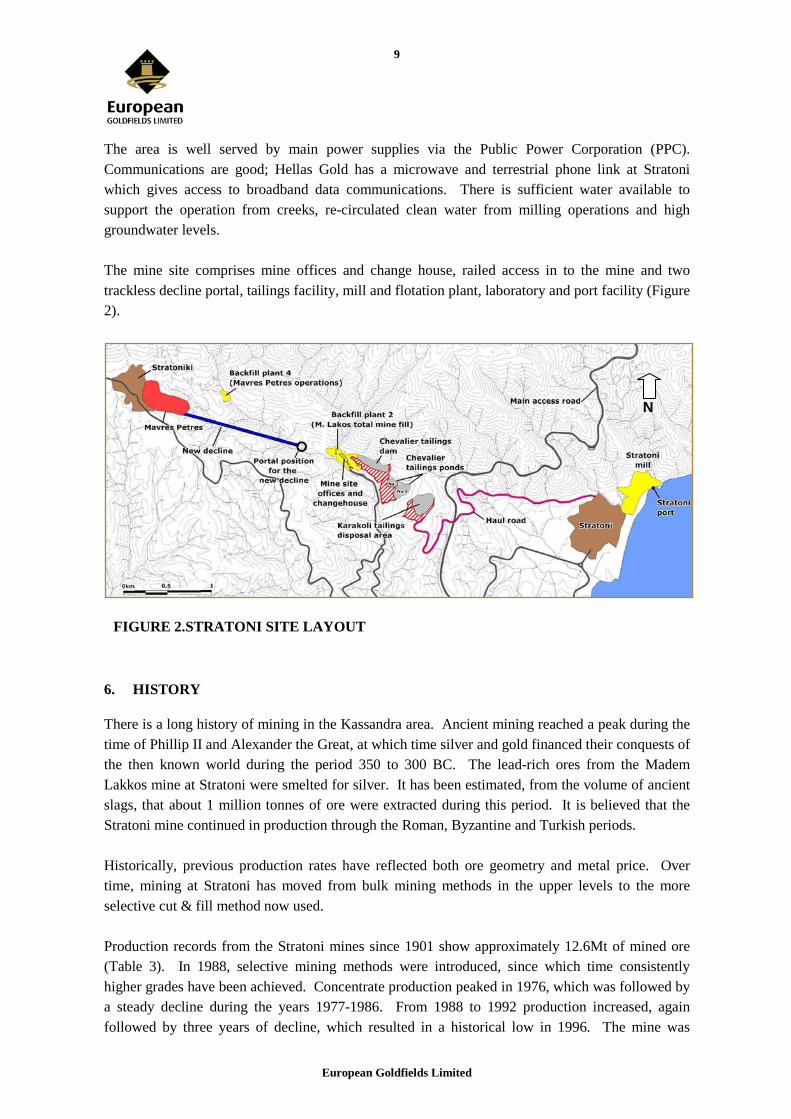
The area is well served by main power supplies via the Public Power Corporation (PPC). Communications are good; Hellas Gold has a microwave and terrestrial phone link at Stratoni which gives access to broadband data communications. There is sufficient water available to support the operation from creeks, re-circulated clean water from milling operations and high groundwater levels. The mine site comprises mine offices and change house, railed access in to the mine and two trackless decline portal, tailings facility, mill and flotation plant, laboratory and port facility (Figure 2).
FIGURE 2. STRATONI SITE LAYOUT
6. HISTORY
There is a long history of mining in the Kassandra area. Ancient mining reached a peak during the time of Phillip II and Alexander the Great, at which time silver and gold financed their conquests of the then known world during the period 350 to 300 BC. The lead-rich ores from the Madem Lakkos mine at Stratoni were smelted for silver. It has been estimated, from the volume of ancient slags, that about 1 million tonnes of ore were extracted during this period. It is believed that the Stratoni mine continued in production through the Roman, Byzantine and Turkish periods. Historically, previous production rates have reflected both ore geometry and metal price. Over time, mining at Stratoni has moved from bulk mining methods in the upper levels to the more selective cut & fill method now used. Production records from the Stratoni mines since 1901 show approximately 12.6Mt of mined ore (Table 3). In 1988, selective mining methods were introduced, since which time consistently higher grades have been achieved. Concentrate production peaked in 1976, which was followed by a steady decline during the years 1977-1986. From 1988 to 1992 production increased, again followed by three years of decline, which resulted in a historical low in 1996. The mine was
N
European Goldfields Limited
10
owned by the Hellenic Fertiliser Company until 1996 when it was taken in to ownership by TVX. Prior to the Hellenic Fertiliser Company the mine was operated by a French-Ottoman company though precise dates of transfer and the manner in which they occurred are not known. Historic resources and reserves are not recorded.
TABLE 3. HISTORICAL STRATONI PRODUCTION (1975-1995)
From 1996 to 2002 TVX owned the operation and their production until they closed the operation in 2002 is given below in Table 4. The operation passed to the Greek state in January 2004 before passing on to European Goldfields subsidiary, Hellas Gold in April 2004.
The tectonic structure of Greece consists of elongated tecto-magmatic belts of variable metamorphic grade which trend northwest to southeast. These broadly coincide with the trend of the main mountain ranges of the country. These zones represent successive episodes of subduction, resulting from the northeast movement of the African plate during the Tertiary period. The rocks that comprise these orogenic zones consist of gneiss, schist and acid igneous intrusives. These rocks host the mineral deposits of the Kassandra Mining District. Three main geotectonic units, following the same trend dominate northeastern Greece; the Rodope massif to the east, the Serbo-Macedonian massif and the Vardar Zone to the west (Figure 3). The Rodope and the Serbo-Macedonian massifs are considered to be part of a metamorphic core complex in the Carpathian-Balkan Alps. The major Strymon detachment separates both massifs.
European Goldfields Limited
12
FIGURE 3. SCHEMATIC STRUCTURAL ZONES OF GREECE
The Serbo-Macedonian massif is sub-divided into two lithostratigraphic tectonic units, the upper Vertiskos formation to the west, with the lower Kerdilia formation to the east. A fault contact separates the two formations. The Vertiskos formation is composed mainly of “two mica” schist with intercalation of quartz lenses. It lacks the pegmatite that characterises the Kerdilia formation. A large less deformed meta-basic body termed amphibolite is located at the contact with the Kerdilia formation. The Kerdilia formation is sub-divided into two units; the Upper and Lower. The Lower Unit mostly consisting of amphibolite gneiss, with lenses of foliated migmatitic rocks, named as Pegmatites (and Aplite). The Upper unit consists mostly of biotite gneiss and schist interlayered with marble horizons, irregular pegmatite lenses and Aplite. The marble horizons of the Upper Kerdilia formation host the ore zones. Both the Kerdilia and the Vertiskos rocks were affected by early ductile and later brittle deformation during the mid-Cretaceous to mid-Tertiary. This resulted from the metamorphic domal uplift that occurred in the area, manifesting itself as a series of folds and faults bounding the metamorphic core. One such fault is the Stratoni fault, a major feature that
European Goldfields Limited
13
dominates the area. During the early Oligocene the district was subjected to extensional tectonics allowing for the intrusion of a post tectonic/metamorphic suite of plugs and dikes. These intrude both the Vertiskos and the Kerdilia formations. Chemically, rocks are in the range of Syenite/Trachyte to Dacite. Examples of these post tectonic intrusives include the Skouries and Fisoka deposits, both of which host gold-copper porphyry mineralisation.
7.2. LOCAL AND PROPERTY GEOLOGY
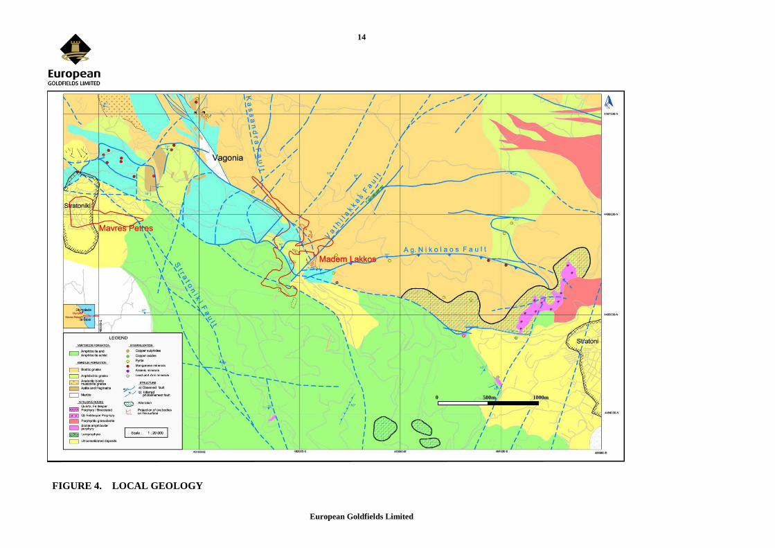
The Stratoni polymetallic ore consists of stratabound replacement mineralisation hosted within the marble horizons of the Upper Kerdilia formation. The mineralised zone is often referred to as the Stratoni-Piavitsa belt; with total sulphide content prior to mining has been estimated at 25Mt. The deposits consist of massive sulphide carbonate and aplite replacement, restricted to two Marble horizons, interlayed with biotite gneiss and schist. The rocks of the Upper Kerdilia formation have been folded into an antiformal structure, known as the Kerdilia antiform. It exhibits an ESE-WSW strike, with plunge to the south-east (Figure 4).
European Goldfields Limited
14
FIGURE 4. LOCAL GEOLOGY
0m
500m 1000m
European Goldfields Limited
15
The Kerdilia antiform is bounded by amphibolite gneiss to the north and the Stratoni fault to the south, with the Stratoni fault separating the rocks of the Kerdilia formation from the “younger” Vertiskos formation to the south. A common feature in the district area is the presence of irregular lenses and vein type intrusions of aplite which post dates both the ore and host rocks. The entire current resources of the Stratoni mine are contained within the Mavres Petres ore body which consists of an east-west lens of Pb-Zn-Ag mineralisation and is generally strata bound within a marble horizon adjacent to the Stratoni Fault or, more rarely, fault controlled in the footwall. Figure 5 is a typical cross section across the Mavres Petres orebody.
FIGURE 5. NORTH SOUTH CROSS SECTION OF THE MAVRES PETRES OREBODY
The mined out Madem Lakkos mine mineralisation lies to the East of and is similar to that at Mavres Petres and occurs in the axis of an antiform within a lower series of marbles. It is noted that there has been no significant exploration of the marbles of either the upper of lower horizons between the two known deposits which lie some 2 kilometres apart. The sulphide ore comprises both undeformed massive sulphides and deformed sulphide ore with the latter characterised by brecciation, mylonitisation, folding and shearing. Similar chemistry and fine zoning of sphalerite in both deformed and undeformed ore suggest that they come from the same system and were deposited after the onset of regional metamorphism. In addition copper-lead-zinc and copper – lead+zinc – silver bulk ore chemistry and lead silver relations, irrespective of deformation, indicate similarity to recognised skarn – replacement type deposits.
16.5m @ 6.4% Pb, 11.7% Zn, 204g/t Ag
16.9m @ 10.9% Pb, 7.5% Zn, 301g/t Ag
31.5m @ 6.7% Pb, 9.0% Zn, 170g/t Ag
25.5m @ 9.7% Pb, 7.7% Zn, 255g/t Ag
18.8m @ 4.4% Pb, 5.91% Zn, 124g/t Ag
18.5m @ 11.6% Pb, 12.7% Zn, 261g/t Ag
37.86m @ 8.4% Pb, 13.8% Zn, 207g/t Ag
11m @ 6.6% Pb, 108% Zn, 1554g/t Ag
2460
0mN
249 0
0mN
2480
0mN
2470
0mN
200mRL
100mRL
300mRL
LEGEND
Section No. 25140mE
Amphibolite
Gneiss
Marble
Massive Sulphide
Stratoni Fault
European Goldfields Limited
16
Fluid inclusion work indicates that both deformed and undeformed sulphide ore were formed from H2O rich CO2 bearing fluids with medium to low salinities fluctuating pressures of less than 500 bar and temperatures of around 480°C and also having complex salt contents.
8. DEPOSIT TYPES
The Stratoni polymetallic ore consists of stratabound replacement mineralisation hosted within marble horizons and may be termed a distal skarn. The mineralisation was emplaced by hydrothermal fluids driven by a granodioritic intrusive which was intruded some 30 million years ago. The mineralised zone is often referred to as the Stratoni-Piavitsa belt, and the total sulphide content of this belt prior to mining has been estimated at 25Mt. The deposits consist of massive sulphide carbonate and aplite replacement, restricted to two Marble horizons, interlayed with biotite gneiss and schist. The model therefore requires two components; marble horizons that have been thickened and structurally prepared by thrusting and folding prior to the introduction of mineralising fluids and; a structural architecture which has allowed the channelling of fluids from a magmatic source to the chemically reactive marbles. Exploration uses these two elements as a guide to identifying potential new ore zones.
9. MINERALISATION
The massive sulphide mineralisation has a relatively simple mineralogy, and the most abundant ore minerals are pyrite, sphalerite, galena, arsenopyrite and chalcopyrite. The dominant exploited minerals historically have been sphalerite, pyrite and galena; the ore is often abbreviated to BPG from the old notation blende, pitch, galena. The ore is also gold bearing, mostly associated with the arsenical pyrite and arsenopyrite. Quartz, calcite and minor rhodochrosite form the gangue minerals. The mineralisation is hosted either in the marble or replacing aplite as irregular and sub-parallel layers of sphalerite, pyrite and galena. These lenses occur from footwall to hanging-wall, varying from few centimetres to tens of metres. Galena is seen as the most deformed mineral, commonly re-crystallised into coarse grains. Galena also exhibits curved cleavage and elongated and foliated grains. Zonation of the sulphides is not clear. The Mavres Petres orebody is some 500 metres in strike length, between 100 and 340 metres in dip extent. The true width is on average 25 metres. The strike of the orebody is close to east west and the dip is 30° to the south. The Mavres Petres orebody shows an average gold grade of around 4 to 6 g/t Au. Its presence is strongly associated with the arsenical pyrite and arsenopyrite, which appears to be a different stage of mineralisation within the matrix of hydrothermal breccias or in veins cutting the Pb-Zn sulphides. The gold mineralisation is not coincident with the massive sulphide mineralisation. The gold is completely refractory and not considered to be of any economic value.
European Goldfields Limited
17
10. EXPLORATION
The Hellenic Fertiliser Company carried out extensive programmes of surface and underground drilling in order to define orebody dimensions and to explore the area around them. Partial logs are available for this work but none of the original cores are available in labelled boxes, none of the holes were surveyed and no assays, certifiable or otherwise have been found. It is believed that ore was identified solely by visual assessment of the core. Where available the partial logs of this work have been entered in to the database but only in order to guide exploration work and for use in the modelling of major geological units. After 1996 TVX conducted intense programme of drilling as detailed below. There has been no historic exploration in the Stratoni area using geophysical or geochemical techniques. Diamond drilling during 2007 totalled 1,403 metres and in 2008 totalled 2088.35 metres. This drilling was completed on extensions to the Madem Lakkos deposit, a zone of mineralisation discovered between the Madem Lakkos and Mavres Petres deposits and on the eastern zone of inferred resources. This drilling and the down the hole surveys were completed by the company’s own drilling crew and by independent drill contractor Drillcon who are based in Sweden using NQ and HQ core with sampling as described below. The 2010 drilling budget on the Stratoni Budget is US$500,000 (approx €330,000) for some 3,000 metres of diamond drilling. Underground sampling of the orebody was carried out in 2007, 2008 and 2009 and this has been included in the current resource. Airborne geophysical surveys using magnetic, radiometric, and EM (electromagnetic) techniques were completed in late 2007. Interpretation indicates conductors to the west of current reserve at Mavres Petres and to the northwest of the mined out Madem Lakkos deposit.
11. DRILLING
The drillhole data used in the resource estimations of the Mavres Petres orebody was from work carried out by previous owners, TVX and from more recent drilling carried out by Hellas Gold. Prior to 1996, 84 surface and 132 underground holes were drilled in Mavres Petres, with 19 surface and 129 underground holes drilled in Madem Lakkos. The vast majority of these holes could not be validated, and concerns regarding their true position and recorded assays resulted in their exclusion from the estimation. After 1996, 332 drill holes were drilled by TVX into the Mavres Petres orebody, all BQ or NQ size. Only the drillholes with collar surveys, and intersections within 50m of the collar were used in the estimation. Holes with intersections beyond 50m were used to assist interpretation. After 1999, downhole survey of holes by Sperry Sun camera was standard practice on all holes greater than 50m. Collar surveys were picked up by total station survey. All hole surveys in the drillhole database were corrected for magnetic declination. Hellas Gold has completed 119 drillholes and continues to survey holes greater than 50 metres length. Core is logged lithologically, all sulphides are logged as BPG, (blende, pyrite, galena), mixed ore (pyrite > blende/galena) and pyritic ore. Lithologies logged were gneiss of various types, marble
European Goldfields Limited
18
and aplites. Structural as well as minor geotechnical information were also logged. The orebody at Mavres Petres is drilled on nominal 25 metre spacing and is open down dip and along strike to the west. The drill orientation with respect to ore is highly variable since most of the holes were drilled in fans from mine infrastructure close to the orebody. Angles to the strike and dip of the orebody range from perpendicular, where drill widths represent true widths, to as low as 30° where drill widths can represent twice the true widths. For this reason particular attention was paid to compositing of the 1 metre samples during the resource estimation process discussed in section 19. All drilling in the current resource was conducted by TVX and Hellas Gold and the logs to these and the sample QAQC (see Section 16) have been validated by the author. Previous drilling is detailed in previous filings. A summary of drilling from 2008 is given below. No sampling was conducted in holes where they ore zone was not encountered. These occurred in areas of potential extension to the orebody rather than in the known orebody itself:-
TABLE 5. DRILLING FROM 2008 AND 2009
Hole-ID From To Drilled width True width Ag Pb Zn MP628 No Sampling MP629 No Sampling MP630 No Sampling MP631 No Sampling MP632 No Sampling MP633 No Sampling MP634 No Sampling MP635 0 6 6 6 117.33 3.52 24.11 MP636 0 22 22 22 212.48 8.15 13.65 MP637 No Sampling MP637B No Sampling MP638 No Sampling MP639 0 25.5 25.5 25.5 287.13 11.89 12.69 MP640 0 5 5 5 214.00 8.44 12.30 MP641 2 12 10 10 73.80 1.78 4.59 MP642 0 28.5 28.5 28.5 311.46 10.68 22.76 MP643 0 1.2 1.2 1.2 40.000 0.135 10.979 MP644 0 2.5 2.5 2.5 65.000 2.303 11.396 MP645 0 80 80 40 253.20 9.91 9.06 MP646 0 81.5 81.5 41 250.270 10.882 9.788 MP647 0 8.8 8.8 8.8 256.250 9.991 15.927 MP648 0 20.5 20.5 15 149.667 5.514 9.304 MP649 0 25 25 25 126.476 4.681 11.496 MP650 0 43 43 35 122.596 4.333 10.433 MP651 0 56 56 40 259 8.235 10.546 MP674 No Sampling MP675 No Sampling MP676 No Sampling MP677 No Sampling MP678 No Sampling MP679 No Sampling MP680 No Sampling MP681 No Sampling MP682 No Sampling MP683 No Sampling MP684 No Sampling MP685 No Sampling MP686 No Sampling MP687 No Sampling
European Goldfields Limited
19
12. SAMPLING METHOD AND APPROACH
12.1. CORE
As a basic rule, the entire ore zone is sampled lithologically, using regular 1m sample interval where possible for a total of some 3,400 samples. Sampling extends 3m into the adjacent waste rock as standard. Internal waste units are sampled individually provided they are greater than 0.75m in length. All samples are marked using permanent marker, with a numbered ticket attached to the core box at the start of each sample. Interval location, hole identification and date of sampling are recorded for each sample on the ticket books. Additionally a short description of the sample is reported indicating the main features. Where sampling core with poor recovery, often only one sample is defined between the core interval pickets. In sectors with better recovery but less than 100%, the real recovered core is proportionally redistributed in the total metreage of the drilling run. Average recovery in sampled areas is greater than 90% and in the opinion of European Goldfields this is sufficient.
12.2. CHANNEL SAMPLING
Underground channel sampling of production faces was implemented by European Goldfields as standard practice, the main purpose being grade control. These channel samples have been used in these resource estimations and total some 350 samples. Samples are taken lithologically and as mining is generally longitudinal, all drifts are sampled by face channels with crosscuts by sidewall channels. Horizontal samples are taken 1m above the floor, which corresponds, to the underground geological mapping elevation. Internal waste units are sampled individually providing the interval is greater than 0.75m in horizontal width. Vertical samples are taken where there is any form of horizontal zonation evident in the face. For sidewall channels, sampling is regularised to 1m intervals, extending 2m out into the footwall and hanging wall waste units. Internal waste units as with face channels are sampled individually. Every third advance is marked for sampling using chip channels of one metre length. Samples are taken in a channel which replicates the size of NQ drilling in order to ensure good sample supports. All sample preparation is undertaken at a sample preparation laboratory at the Stratoni Mill. All samples are subsequently assayed for Ag, Pb and Zn. Quality Control of assaying in the historic drill holes and underground channels has been undertaken by cross-checking 10% of pulps and 10% of the coarse rejects. This has showed that the channels and the drill hole samples are comparable datasets and that there is no significant bias in either. The fact that 1 metre sample intervals are used for both the drilling and the channel sampling and that the size (volume) of the channel samples is equivalent to drill core, means that the two sampling media offer equal sample support. There are no significant geological changes within the orebody that need to be considered in sampling except for discrete waste zones, called ‘waste potatoes’ which are sampled and modelled separately. As such both the drill core samples and the channel samples are seen as representative. The variability of sample orientation due to the
European Goldfields Limited
20
nature of the fanned underground drilling and the channel sampling of both side walls and faces within the operation has not proved problematic due to the massive nature of the mineralisation. There are no significant dilution effects in the sampling since the contact between mineralised and non- mineralised material is abrupt, generally passing from massive sulphides to either barren marble or gneiss in the footwall of from massive sulphide to fault kaolinite in the hanging-wall.
13. SAMPLE PREPARATION, ANALYSES AND SECURITY
All sample preparation is undertaken at a sample preparation laboratory on site. All samples are subsequently assayed for Ag, Pb and Zn. Sample analysis is via aqua regia and AAS. Drill samples inside the ore envelope were also assayed for Fe. The primary laboratory used is the mine laboratory in Stratoni, whilst ALS Chemex are the secondary laboratories. The Stratoni laboratory used for primary assays was certified according to the ISO 9002 standard under the scope "Preparation and Chemical Analysis of Geological Mining, Metallurgical and Environmental Monitoring Samples, Certificate No 53987" for data up to 2003 when the operation closed. Since re-opening the laboratory put in an application for ISO certification in 2008. The ALS Chemex laboratories are certified under ISO 9002 under the same scope as Stratoni. Since 1999, Quality Control of assaying has been undertaken by cross-checking 10% of pulps and 10% of the coarse rejects. This is viewed as sufficient for a massive sulphide base metal orebody and has been maintained for the current period of production. Following a specific gravity measurement programme involving over 600 samples by both volumetric and geometric methods, the decision was taken to use a constant density for massive sulphide of 4.2 g/cm3 was used. Waste has been assigned a SG value of 2.75 g/cm3. Quality Control of assaying in the historic drill holes and underground channels has been undertaken by cross-checking 10% of pulps and 10% of the coarse rejects. Quality control samples were sent to the ALS Chemex laboratory in Vancouver, Canada and at the ALS Chemex laboratory at Gura Rosiei, Romania. The sample preparation, sample security and QAQC are, in the author’s opinion, of a high standard and ensures the sample database is not biased.
14. DATA VERIFICATION
A comparison of quality control samples and also between channel and core samples was carried out using regression analysis. There was found to be no significant bias in the sample data. The author has also carried out a comparative study between the drill core sample assays and the channel samples using comparison of means and composite means. The author has also verified the data. These indicate that the samples all belong to the same statistical population as displayed in the plots in section 19.2. In the authors opinion the sample database is representative with no significant bias.
15. ADJACENT PROPERTIES
Not Applicable
European Goldfields Limited
21
16. MINERAL PROCESSING AND METALLURGICAL TESTING
16.1. INTRODUCTION
The Stratoni concentrator plant is currently campaign milling at a rate of +/- 40 t/h of Run of Mine (ROM) ore from the Mavres Petres mine. The ore is mined at a lower rate and stockpiled ahead of the crusher and run in campaigns so as to provide continuity of concentrator operation thereby minimising the disruptive effect on metallurgical performance. During 2009 the throughput was 226,784 dry metric tonnes. Lead and zinc recoveries of 92%and 93% respectively were achieved; the silver recoveries to the lead concentrate was 84% and to the combined lead and zinc concentrates was 93%. The grade of the bulk lead/silver concentrate averaged 67% Pb and 1,585 g/t Ag; the zinc concentrate contained 49% Zn. Representivity is not an issue as the data is based on results from the operating plant not samples from drilling. Concentrates are shipped by sea using the Stratoni or occasionally (if stipulated by the purchaser) the Thessaloniki sea port facilities. Current arisings of coarse tailings are being used for mine backfill. The fine tailings are processed using a filter press and the resulting filter cake is sent to the Karakoli area and the clear filtrate water recycled. Once the clearance of the Chevalier tailings settling ponds is complete, they can also be used for storage of the fine tailings filter cake. The coarse fraction of old tailings with no economic value are currently being used for backfill. As a consequence of the major rehabilitation work and structured planned maintenance, high plant availability has been achieved, the campaign milling operation allows maintenance of the mill and plant between campaigns.
16.2. PROCESS DESCRIPTION
16.2.1. CRUSHING
The crushing facility has spare capacity and is capable of crushing up to 750,000 dmt per annum and as a consequence is currently only operating for approximately one third of the available time. Maximum crushing capacity is 170 dmt/hr, but normal operating capacity is 120 dmt/hr. The ore is received from the mine in trucks and dumped onto an ore storage area. Ore is reclaimed from the storage area by FEL and dumped into a hopper feeding the crushing plant. The ore is dry crushed to minus 20mm size in three stages of crushing using a primary jaw crusher, a standard Symons secondary crusher and two shorthead Symons tertiary crushers. The standard Symons crusher operates in open circuit with a vibrating screen while the shorthead Symons crushers operate in closed circuit with two other vibrating screens. The crushed ore is conveyed to the fine ore bin.
European Goldfields Limited
22
16.2.2. MILLING AND FLOTATION
A block diagram of the operation at Stratoni is shown in Figure 6 below.
FIGURE 6. STRATONI PROCESSING FLOW SHEET
Ore is automatically fed at a controlled tonnage from the fine ore bin and subsequently wet ground to a nominal 80% minus 212 microns in a conventional rod mill/ball mill circuit. The rod mill operates in open circuit while the ball mill operates in closed circuit with a 500 mm cyclone. The flotation scheme is operated in the differential mode. Lead is floated first and the zinc minerals are subsequently recovered from the lead circuit tailing. The cyclone overflow passes to a conditioner and then to the lead roughing and scavenging flotation cells. The lead scavenger concentrate returns to the lead conditioner or to the feed cyclone. The lead rougher concentrate is cleaned in three stages to produce a final lead cleaner concentrate. Standard reagents and pH control are used in the flotation circuit to achieve the production of the two concentrates. The initial reagents are added to the rod mill and further additions are staged through the circuit. The zinc circuit configuration of conditioning, roughing, scavenging and cleaning is similar to that for lead except for an additional stage of cleaning.
PbS Pb:
67%
8%
ZnS Zn:
49%
16%
SLUDGE SEA
~200 m3/h
FILTER PRESSES
76%
FILTER CAKE DISPOSAL AT TAILINGS FACILITY
CONCENTRATE PRODUCTION
Ultra Fines
Coarse
NEUTRALISATION
WATER
WASTE ROCK
BACKFILLING
TAILINGS
MINE WATERS
MINING AREA
FLOTATION
SULPHIDE ORE Pb:6.3%, Zn:8.5%, Ag:177 g/t
European Goldfields Limited
23
The roughing and scavenging flotation cells are Outokumpu 3 cubic metre cells arranged in banks of six cells. In each bank the first cell has a pumping action in the mechanism which enables all of the flotation cells to be on the same level. All cleaning is done in Denver No. 24 Sub-A, 1.5 cubic metres cells. A 13 metre diameter thickener and a 1 metre diameter by 4 disc filter are used to dewater lead concentrate. Typical lead concentrate moisture content is 7%. Two 10 metre diameter thickeners and a 1 metre diameter by 5 disc filter are used to dewater zinc concentrate. Typical zinc concentrate moisture content is 8%. The lead and zinc concentrates are weighed and conveyed to storage sheds awaiting shipment to the smelter. Investigations are being undertaken to optimise the cleaner circuit and it is planned to install additional flotation cells to test the configuration on the plant. Generally metallurgical performance is very good and well understood.
16.2.3. MATERIAL BALANCE
Metallurgical accounting is carried out by sampling at predetermined points in the flow sheet on a 24 hour accounting basis. All assays are conducted by wet chemistry and this system was previously ISO 9002 approved. It is proposed to have the analytical services laboratory re-accredited. Conveyor belt weightometers are used for the recording of feed and concentrate tonnages and are continuously monitored. The concentrate load out facility has its own accredited weightometer and is used to weigh out shipped concentrate lots. QC/QA procedures are implemented to assure and maintain accurate scale operation.
16.3. INSTRUMENTATION & CONTROL
During the year a previously installed On Stream Analyser supplied by Amdel was re-commissioned and has operated well. The system takes timed samples from important process streams, analyses for the important elements including lead and zinc and displays the data in the Plant control room. This provides real time information display to the operators in order to maintain optimal metallurgical performance. The quality control laboratory is located at the Stratoni mill main building and is responsible for sample preparation, fire assay and wet chemistry. A major renovation project was undertaken in 1997, including the complete refurbishing of premises and analytical equipment. The laboratory was certified according to the ISO 9002 standard under the scope "Preparation and Chemical Analysis of Geological Mining, Metallurgical and Environmental Monitoring Samples, Certificate No 53987". It is proposed to apply for re-accreditation.
European Goldfields Limited
24
16.4. ELECTRICAL SUPPLY & DISTRIBUTION
The present electrical supplies to Stratoni operations are obtained from the Public Electricity Supply Company (PPC). PPC supply an overhead line of 10 km at 20kV, which terminates at a power terminal pylon located at the Stratoni mill facilities, close to the tailings plant. Power is taken from the pylon via two underground cables. The first cable, equipped with two 1600KVA transformers, feeds the sub-station of A΄ B.P.G, which in turn feeds the shipment facility, mine water treatment plant, maintenance shop, electrical workshop, and chemical and metallurgical laboratory. The second cable feeds a second sub-station located beside the mill electrical workshop. This sub-station consists of: • A transformer for the tailings plant – 800KVA; • A transformer for the new crushing plant – 800KVA; and • A transformer for the Stratoni main offices and warehouse – 400KVA, and one power line feeding the Madem Lakkos mine. The line feeding the Madem Lakkos/Mavres Petres mine is equipped with three transformers. These are located at Stratoni Villa (100KVA), +53m adit (150KVA) and at the tailings pond (250KVA). The line continues and feeds the two sub-stations located at the Madem Lakkos mine.
16.5. CONCENTRATE HANDLING FACILITIES
Concentrate handling facilities include installations and equipment used for ship loading. Concentrates are conveyed and stored under a shed of 7,500m2. Ship loading is effected at a rate of 400 - 500 t/h depending on concentrate type.
16.6. FINE TAILINGS
Hellas Gold’s responsibility to both the environment and local communities continues with the full implementation of the tailings plan minimising surface storage and maximising underground disposal. A key part of the strategy was the commissioning and successful operation of the filter presses for dewatering fine tailings. The newly installed filter presses at the Stratoni Mill and near Mavres Petres Mine enables the processing of fine tailings and water treatment sludge to filter cake which is back-hauled to the tailings storage area at Madem Lakkos and has replaced the pumping of slurry for these by products. This has lowered costs and also reduced the required space for fine tailings and water treatment sludge storage.
17. MINERAL RESOURCE AND MINERAL RESERVE ESTIMATES
17.1. GEOLOGICAL MODELLING
The geological model is based on two main sources of information:-
European Goldfields Limited
25
• Mapping carried out within the mine during European Goldfields period of operating the mine between November 2005 and December 2008. • The existing diamond drill core database as detailed above
17.1.1. FACE MAPPING
Each operating face is mapped and logged on to a 1:50 scale sheet of graph paper noting the following:- • Footwall ore / marble contact, • Hanging wall contact if exposed • Any internal waste zone contacts, • Any zoning of sulphides, • The marble / gneiss contact if present • Any foot wall faulting Where present the following features are then be marked up in white paint:- • Footwall contact with waste side clearly marked • Waste zone contact with waste side clearly marked • Any clear mineral zones such as massive galena or sphalerite. An example of a marked face with sample points is shown below in Figure 7:-
European Goldfields Limited
26
Gale
na ri
ch z
one
Mixed
sul
phid
e zo
ne
Footwallwaste
Internalwaste
Sample channels (every 3rd advance)
4m
4m
FIGURE 7. EXAMPLE OF FACE MAPPING
17.1.2. WIREFRAME
The geology from mapping and drillhole logs is transferred on to level plans at 1:500 scale. These are then digitised in to Gemcom software. The plan outlines of the limits of the massive sulphide mineralisation are then linked in to a 3D wireframe. This was then sectioned at 25 metre intervals and adjustments were made in order to ensure all known mineralisation as defined by underground mapping and sampling and by drillholes was included in the wireframe. Solid models of all underground excavations are generated as standard practice. Some of the remnant resources considered non-mineable were then incorporated into these excavation solids, to ensure that they are discarded from the resource tonnage total during reporting. Only samples that fall inside the geological solid are used in the resource estimation. As a significant proportion of the drilling at Mavres Petres has not been on true geological sections, this has resulted in problems of correct data capture. To ensure the correct samples are selected, close attention was paid to drillholes that were drilled sub-parallel to the orebody as these include un-mineralised core that would fall inside the wireframe. It has been found that whilst the hanging wall is very regular due to it being tightly controlled by the Stratoni Fault, the footwall is far less predictable with frequent ‘blows’. Mapping by European Goldfields indicates that these irregular features are controlled by footwall faults and in some cases basal thrusts which limit the extent of the marble units. These require detailed mapping and possibly more closely spaced drilling in order to establish their full extent. The current wireframe tends to be conservative in the tonnes it estimates because it does not include all of the footwall ‘blows’.
European Goldfields Limited
27
17.2. SAMPLE STATISTICS
The drillhole samples are held in a Microsoft Access database in multiple tables. In order to estimate geological resources using geostatistical methods it is necessary to deal with equal sample supports, which was achieved by compositing the sample data. Prior to the compositing process, to ensure quality of the data used in the resource estimation is representative, a review of all drillhole samples within the orebody solids was undertaken. Primarily this was to ensure that missing intervals and/or non-sampled intervals were treated correctly. Following a review of the final sample database to be used for the estimation, a 2m composite interval was selected as the most appropriate. Comparison of the arithmetic means between both raw and composited data shows compositing slightly reduces the grade in most cases, and thereby does not result in an over-estimate. Analysis of normal and log normal histogram and probability plots indicate that lead, zinc and silver approximate log normal populations, as indicated in the following log normal histograms:-
FIGURE 8. LOG NORMAL HISTOGRAM OF LEAD DATA
Real Value
Frequency Count
1.000 10.000 100.000
14
28
41
55
69
Pb LOG Normal Histogram Mavres Petres Solid 2m Composites
Software By Gemcom
European Goldfields Limited
28
FIGURE 9. LOG NORMAL HISTOGRAM OF ZINC DATA
FIGURE 10. LOG NORMAL HISTOGRAM OF SILVER DATA
Real Value
Frequency Count
10.000 100.000 1000.000 10000.000
31
62
93
124
155
Ag LOG Normal Histogram Raw M Petres DDH
Software By Gemcom
Real Value
Frequency Count
1.000 10.000 100.000
26
51
77
102
128
Zn LOG Normal Histogram Raw M Petres DDH
Software By Gemcom
European Goldfields Limited
29
Simple scatter plots also show that there is a close correlation between lead and silver, confirming that silver is associated with galena, whilst zinc and lead show no correlation:-
FIGURE 11. SCATTERGRAM OF LEAD AND SILVER DATA
FIGURE 12. SCATTERGRAM OF LEAD AND ZN DATA
17.3. VARIOGRAPHY
3D variograms were run for lead, zinc and silver on the 2 metre composites. As the geometry of the ore is broadly consistent, omni-directional, as well as directional variograms along strike, dip and perpendicular to the orebody were calculated for each element. Lag distances of 5m were
generally used. The average sample spacing downhole is 1m, sample spacing along strike varies between 10-20m. The best variogram structures for lead and silver were all found in similar directions of 240° azimuth, with 30° dip. These directions are within the plane of the orebody, following a down-plunge direction towards the SW. Zinc is less distinct but the best semi-variogram has an orientation of around 300°. This could well indicate a quite distinct episode of mineralisation, either as an overprint or a remobilisation and this is supported by visual observation of the breccia zones that are zinc rich and are apparently associated with footwall fault structures. In all three elements reasonable omni-directional semi-variograms were obtained and these were modelled within Gemcom in order to provide parameters for kriging. The settings for the models are tabulated below:-
TABLE 6. VARIOGRAM MODELS
Element Nugget (Gamma)
Spherical Model 1 Sill
Spherical Model 1 Range
Spherical Model 2 Sill
Spherical Model 2 Range
Lead 18.45 45.55 43.96 NA NA Zinc 14.55 41.02 14.46 11.25 66.39 Silver 13750 27084 42.5 NA NA The following plots show the semi-variograms and models graphically:-
FIGURE 13. LEAD SEMI-VARIOGRAM
Range [m]
Gam
ma
(H)
0 15 30 45 60 75 90 105 120 135 1500
22.683
45.367
68.050
3D Semi-variogram 1-Az:240 Dip:-30PB (UG Channels & Composite solid 2m)
Software By Gemcom
#
1) Nugget Effect( 18.45)
*
2) Spherical( 43.96, 45.55)
European Goldfields Limited
31
FIGURE 14. ZINC SEMI-VARIOGRAM
FIGURE 15. SILVER SEMI-VARIOGRAM
Range [m]
Gam
ma
(H)
0 15 30 45 60 75 90 105 120 135 1500
23.200
46.399
69.599
3D Semi-variogram 1
Software By Gemcom
#
1) Nugget Effect( 14.55)
*
2) Spherical( 14.45, 41.02)
*
3) Spherical( 66.39, 11.25)
Range [m]
Gam
ma
(H)
0 15 30 45 60 75 90 105 120 135 1500
14150.770
28301.541
42452.311
3D Semi-variogram 1 Az:240 Dip:-30Ag UG+Composite solid 2m
The following comments stem from the variogram analysis: • The total variogram ranges vary from some 40m to 60m dependent on element. • Lead and silver behave similarly as expected. They both exhibit good variogram structures with ranges in excess of 40m. • Zinc also exhibits a good structure with a range above 60m but required two spherical models in order to replicate the semi-variogram. This suggests that zinc is bimodal and points to either an overprint or remobilization of zinc.
17.4. BLOCK MODEL
Block models were generated using Gemcom software. The main model properties are as follows:
TABLE 7. SEARCH ELLIPSOID PARAMETERS
Block model parameters Min X 24900m Max X 25500m Min Y -24900m Max Y -24500m Min Z 0m Max Z 400m Model Rotation 0 Number of Columns 300 Number of Rows 200 Number of levels 200 Column Width 2m Row Height 2m Level Height 2m
Interpolation of block values from the 2 metre assay composite database was carried out using ordinary kriging (OK) using the models defined in the variography analysis. The interpolation was carried out in 3 passes for each element, each pass having different search ellipsoid parameters. In each case the search ellipse principal axis was along the strike of the orebody, the secondary axis was down dip and the tertiary axis was across the true thickness. The search ellipsoid parameters were as follows:-
TABLE 8. SEARCH ELLIPSOID PARAMETERS
Principle Axis (Gemcom X)
Secondary Axis (Gemcom Z)
Tertiary Axis (Gemcom Y)
1st run 35m 25m 15m 2nd run 70m 40m 25m 3rd run 150m 90m 60m
European Goldfields Limited
33
After interpolation the whole orebody was checked on 10 metre spaced sections and all mining level planes (generally 4 metre spacing) for correlation of raw assay data and interpolated block values and these were found to be acceptable for all elements.
17.5. RESOURCE CLASSIFICATION AND TABULATION
The Mineral Resource estimation has been carried out by Mr Patrick Forward, BSc (Mining Geology), MAusIMM, who is an employee of European Goldfields. European Goldfields has adopted the Canadian Institute of Mining (CIM) classification of geological resources for reporting purposes. The CIM classification has been applied to Stratoni through the following set of practical guidelines:- All resources All mined areas and areas effectively sterilised by mining, classified as ‘99’s’, were excluded. Categorisation was considered on a mining level by mining level basis as follows:- Measured Resources • ore blocked out within the geological orebody solid • ore blocked out where the average interpolation distance for the level was less than 20 metres Indicated Resources • ore blocked out within the geological orebody solid • ore blocked out where the average interpolation distance for the level was less than 20 metres. This took in all the ore within the wireframe. Inferred Resource This category is defined by ore, which satisfies the following criteria:- • Ore panels which can be reasonably assumed to occur beyond the defined orebody wireframe where the orebody extension has been shown to be open. These were developed as simple panels using the average orebody thickness in the relevant part of the orebody and the average grade of the orebody and a maximum extrapolation from known sample data of 75 metres. Tonnages were rounded to the nearest 1,000 tonnes. These can be summarised as follows:-
European Goldfields Limited
34
TABLE 9. INFERRED RESOURCE PANELS AT MAVRES PETRES
Strike Down Dip True Width Density Tonnes Rounded tonnes East 40 20 20 4.2 67200 67000 Lower central 100 40 20 4.2 336000 336000 West 80 40 20 4.2 268800 268000
TOTAL 672000 671000 The total remaining resources at Mavres Petres can be summarised as follows:-
TABLE 10. REMAINING RESOURCES AT MAVRES PETRES
‘000t Ag Ag Pb Pb Zn Zn g/t Moz % ‘000t % ‘000t
Measured Measured 1,694 216 11.8 7.7 130 10.8 Indicated Indicated 122 236 0.9 9.1 11 10.4 Total Total 1,816 217 12.7 7.8 141 10.8 Total Inferred Total
No cut-off grade is applied to the above model since the mineralisation is highly discrete and marked by a sharp contact between the massive sulphides and the barren wall rocks in both the footwall and the hanging wall. The Mineral Resource and Mineral Reserve is not affected materially by legal, environmental, title, taxation, socio-economic, marketing or political issues and the Stratoni Mine is a fully permitted producing operation at the time of writing this report. The impact of metallurgy, mining and other technical factors and the relevant levels of operating cost, capital requirement and taxation are detailed below in the discussion of Mineral Reserves.
17.6. RESERVES
Historic mining at the Mavres Petres mine was mainly below the main access and ore haulage on +260m level. The proposed future mining is mainly completing the mining in these upper areas, but also mining the fully explored down dip extension to the orebody below +260m level. There are 2.3 million tonnes of proven and probable reserves remaining in the Mavres Petres mine which will support a maximum mining rate of 400 ktpa. The geotechnical conditions described below influence strongly the choice and layout of mining methods. These methods chosen for future mining are equivalent or similar to those that have historically proven to be appropriate for the Stratoni orebody and hence no risk is anticipated in the mining method. A general view of the orebody with existing development and proposed major development is shown in Figure 16.
European Goldfields Limited
35
FIGURE 16. THREE DIMENSIONAL VIEW OF THE MINE LAYOUT
17.6.1. GROUND CONDITIONS
Previous mining has generated a lot of experience with the ground conditions and the rockmass physical and geotechnical characteristics. In general, the footwall and orebody rocks can be described as Fair to Good with Poor conditions relating to the presence of Kaolinite. Table 11 below gives the average Uniaxial Compressive Strength (UCS) of the Stratoni rock types.
TABLE 11. UNIAXIAL COMPRESSIVE STRENGTH (UCS) OF STRATONI ROCK TYPES
Fortunately, the majority of kaolinite is associated with the hanging wall fault which is not exposed by mining. Some kaolinite may be present in the ore close to the hanging wall contact and in fault intersections in development.
410 Drift
360 Drift
Old Caved Area
New 360 Decline
Existing Railed Access
Ore Trackless Decline to +140m
European Goldfields Limited
36
17.6.2. SUPPORT
Stope support to the longitudinal or transverse drives is to be on a one meter grid pattern utilising 2.1 metre Swellex bolts. Support to the slashed area is as required. Development support is also on a one metre grid pattern. In the past, steel sets were installed in the kaolinised areas, but in more recent times fibre reinforced shotcrete is used where possible, though steel sets have been utilised in the upper part of the mine where access is difficult.
17.6.3. SURFACE SUBSIDENCE FROM BACKFILL MINING
A geotechnical simulation of the recent backfilled and proposed future backfilled mining zones has been carried out. The backfill prevents caving and collapse into the workings so that the only mining induced deformation is elastic. The mining simulation gives theoretical maximum lowering of the surface at its final long term subsided position of 4.5mm based upon elastic deformation. With these levels of movement, it was concluded that no damage will be caused to the existing and future surface installations.
17.6.4. SEISMICITY
The Stratoni fault was the source of a major seismic event in September 1932. This resulted in the fault opening up to a width of 2m, with a depth of around 10m and traceable on surface from Stratoni to Stagira, a distance of around 15 km. The fault extends under the sea following the northern shore of the Stratoni bay. The 1932 event was a deep seated event and because of the relatively small amount of mining and the use of backfill to fill the voids, the future mining at Mavres Petres is not considered a likely trigger for further seismicity on this structure.
17.6.5. MINING OVERVIEW
The ore zones at the Mavres Petres mine are variable in ore geometry and ground conditions. The ore contacts are well defined and are often irregular on the footwall. The high grades associated with these types of ore dictate that a selective mining method is used. The mining method is a combination of transverse and longitudinal cut & fill. Rock breaking is by conventional drill and blast. The method is flexible, allowing headings to change direction with changing ore geometry. The Government’s Ministry of Industry has approved this mining method.
European Goldfields Limited
37
17.6.6. RAMP AND ACCESS CROSS-CUTS
A main ramp has been driven in the footwall down to the +120m level and up to the +300m level. In some of the upper area of the mine, twin ramps have been driven in order to increase the productivity of the stopes. Access crosscuts to intersect the orebody are driven from the main ramp. The average length is 30 metres. The mining of a new decline from surface to the bottom of the currently defined orebody is now complete and will allow safer mining and more efficient application of new mining technology allowing a ramp-up of production. In addition, the decline will provide access to areas of potential orebody extension. Development completed includes the extension of the main ramp upwards to the +300m level and planned development down to the +100m level. An additional decline connecting to the upper part of the mine (+290m level) to facilitate extraction and ventilation in this area is complete.
17.6.7. STOPE DEVELOPMENT
Production in ore commences after the access crosscut where the ramp reaches the footwall of the orebody, usually midway along its strike length. The crosscut is driven through the orebody to expose the hanging-wall. In the narrow areas, often only a single heading is mined longitudinally to the east and west. Once the strike extent of the ore is reached, the stope development stage is complete. The stope development heading is usually 4.0m x 4.0m. This may be adjusted to allow for pinching and swelling. Each mining level will be developed for longitudinal or transverse stoping. Generally, for footwall to hanging-wall thickness of 10 metres or less, the stope will be developed for longitudinal mining (Figure 17). For a thickness greater than 10 metres, the Transverse Method is preferable (Figure 18) where a drift is driven along the centre of the orebody, from which transverse drifts are mined to the hanging-wall and footwall on the retreat from the ends of the orebody. This method of mining from footwall to hanging-wall has the advantage of offering increased hanging-wall stability by reducing the area of exposure at any one time. Where primary and secondary mining is scheduled, productivity is also increased as a single stoping level will have many more available faces than with the longitudinal method. If the distance between the hanging-wall and the footwall is very variable from narrow to wide, then a mixed method of longitudinal and transverse development would be adapted to suit the conditions.
European Goldfields Limited
38
FIGURE 17. LONGITUDINAL MINING TO A NARROW AREA OF THE OREBODY
FIGURE 18. TRANSVERSE MINING TO A WIDE AREA OF THE OREBODY
17.6.8. STOPING
Following completion of stope development, the main stoping phase begins. The sidewalls of the development drive are stripped where possible up to 3 metres from either side, beginning at the end of the transverse or longitudinal drift. Experience of the ground conditions in the Mavres Petres orebody indicates that the total width of the stripped drive must be limited to 10 metres. The stripping process continues until the designed barricade position.
Access
Plan View
Section AB
A B
Access
Access
Plan View
Section AB
A
B
European Goldfields Limited
39
Ore is removed from the stope after blasting, using load haul dump machines. It is tipped into the orepass system alongside the main ramp or in the lower areas directly into the dump trucks. A loading bay is developed if logistically necessary. The stoped area is then filled.
17.6.9. BACKFILL
The first retreat must be stabilised with backfill before any remaining ground can be taken. Hydraulic cemented backfill will be of the recipe dictated in the monthly mining schedule to be submitted by Hellas Gold. The stope is prepared with suspended fill discharge pipes to the highest points and barricaded at the neck of the development drive with timber round poles, planks and filtration fabric. The sidewall adjacent to the next stope is covered with mesh which will serve to reinforce the backfill wall which remains as its neighbour is stoped. In the case of underhand cut and fill, the floor is covered with a membrane and reinforcing mesh before filling. Additionally, ties of 20mm diameter connect to the mesh and up to the back of the excavation at a density of one every 3 metres to reinforce the slab. Fill is poured via 5 and 6 inch pipes from surface at a rate of approximately 40 cubic metres per hour. Tight fill is essential to safe operation in drift and fill mining. The method of achieving tight fill at Stratoni is to develop the drifts at a 2% upgrade. Fill pipes with breather pipes are placed at the middle and the end of the stope. The filling starts at the middle pipe until the tails appear in the breather pipe, then filling changes to the end fill pipe. This works well when closely supervised, and the 2% gradient is sufficient for tight fill without undue pressure knocking the door down.
17.6.10. DILUTION AND RECOVERY
Variable recovery and dilution values have been assigned for the purpose of updating the Stratoni mineable reserves. These are based on a combination of factors, chiefly, mining method, deposit geometry, sidewall rock conditions, and deposit thickness. For recovery, the following assumptions have been made: • Losses in ore wedges are determined geometrically from using only the tonnages within
realistic stope designs. • Minimum 2.6m height required for scoop to muck in hanging wall. • An overall recovery of 95% from the stopes is assumed For waste rock dilution, the following assumptions have been made:
European Goldfields Limited
40
• An allowance of 25% of the above dilution has been made for discontinuities in the deposit and failure to follow the contact accurately.
• Waste rock has been assigned the following grades: 0.6% Pb, 1% Zn, 12 g/t Ag, based on interval weighted average of assays in the 2m envelope around the defined mineralisation.
• SG waste rock: 2.7 t/m3 For backfill dilution, the following assumptions have been made: • Sidewall Dilution: 0.25m • Roof Dilution: 0.25m (this will only occur occasionally where old mine workings or sill pillars
force under hand cut and fill to be used. Therefore, a factored value of 0.05m was used in the calculation.)
• Floor Dilution: 0.25m • Dilution from backfill is assumed to have zero grade • SG Backfill: 1.8 t/m3 These factors resulted in an overall recovery of 95% of designed stopes and an average dilution of 10%.
17.6.11. CUT OFF GRADE
For each block in the resource block model a net smelter return (NSR) was calculated using current metal prices and payable factors given below in section 19.6.12. This was then compared to a Euro value cut off of €81.5 using the life of mine average operating costs. The very limited amount of individual blocks that fell below these values were not of sufficient size to be excluded from the mining plan and are therefore diluted in to the model.
17.6.12. FINANCIAL INDICES
The following schedule and financial indices were developed for the project from a detailed analysis of operations throughout 2007:-
An economic model has been developed using the above parameters on the Mineral Reserves alone, with no inclusion of inferred Resources and shows an acceptable net present value for the project. Internal rate of return and Payback are not applicable as the operation is up and running with no significant capital expenditure required i.e. there are no negative cashflow years. Taxes are calculated at 25% and depreciation at a rate of 15%.
17.6.14. TABULATION OF RESERVES
The total reserves can be summarised as follows:-
European Goldfields Limited
42
TABLE 13. CURRENT RESERVES
‘000t Ag Ag Pb Pb Zn Zn
g/t Moz % ‘000t % ‘000t
Proven 1,657 174 9.3 6.1 101 8.5 141
Probable 103 225 0.7 8.7 9 9.3 10
Total 1,760 177 10.0 6.3 110 8.5 150
Note: Included in resources above
18. OTHER RELEVANT DATA AND INFORMATION
18.1. WATER MANAGEMENT
18.1.1. GENERAL SITUATION
There are two main places where surface water enters the mines, the valley below Stratoniki for Mavres Petres and the Giovanos valley for Madem Lakkos. This water exits the Madem Lakkos mine through the +53m portal and exits the Mavres Petres mine from the +216m haulage. Mine water is directed to the water treatment plant, located next the Stratoni concentrator. A second water treatment plant with similar capacity and of a similar design to that at the Stratoni mill is in operation at the Madem Lakkos mine to improve efficiency and provide capacity for extreme rainfall events. The plant includes a filter press to allow dry storage of filter cake. The general flow of groundwater and current water treatment plants are shown in Figure 18.
FIGURE 19. SCHEMATIC OF GROUNDWATER FLOW CONDITIONS
European Goldfields Limited
43
The treatment is carried out in agitated reactors with hydrated lime for neutralisation, which results in precipitation of the dissolved metals. The neutralisation pulp undergoes thickening and the clarified overflow water is discharged to the sea. The thickener underflow is co-disposed with the fine flotation tailings as filter cake on the Karakoli dam area following treatment with filter presses. The quality of the final effluent after treatment in the neutralisation plant fully complies with the environmental limits set for the discharge of industrial effluents in the Stratoni bay.
FIGURE 20. SCHEMATIC WATER RETICULATION
18.1.2. GROUND WATER FLOW AND UNDERGROUND DEWATERING
Greek regulations for mining and quarrying stipulate that the mine must have pumping capacity equal to twice the estimated maximum inflow of water plus spare capacity equal to the maximum estimated inflow. This means that at each of the pumping stations there must be two separate pumping systems, one with the capability of pumping twice the maximum inflow of water and the other with the capability of pumping the maximum inflow of water, each through their own dedicated pipelines. The maximum current inflows are 70m3/h into the shaft at Madem Lakkos and 100 m3/h into the +216m haulage of Mavres Petres. The quality of the steady state flow Madem Lakkos water is
Ag
AGGREGATE
MAVRES PETRES MINE
WASTE ROCKPROCESSING
TAILINGSCLASSIFIER
NATURALRECEIVERS
Coarse+ Cement
ZnS
MINE WATER
FLOTATION
CLEAN WATERTANK
Fines
MIXED SULPHIDE
ORE
PbS
Saleable Products
BACKFILL
COMMERCIAL PRODUCTS
STACKING OF FILTER CAKEIN CHEVALIER PONDS
NEUTRALISATION
MINE WATERTANK
NEUTRALISATION SLUDGE
EMERGENCY STORAGE FACILITY
THICKENER
Overflow
Underflow
MIXING
WATER RECYCLED TO ENRICHMENT PLANT
FILTER PRESS
REJECTED QUALITY
APPROVEDQUALITY
Stockpiling/Thickening &Filtering Unit
OLD MADEM LAKKOS MINE
NEW DISPOSAL SITE KOKKINOLAKKAS
European Goldfields Limited
44
already at discharge quality without treatment, but that of Mavres Petres has a low pH and contains dissolved metals content of up to 2,500mg/l. It should be noted however that for worst conditions during peak storms, short term discharge rate of close to 1,000m3/h have been recorded. The Madem Lakkos mine is relatively dry, with minimal groundwater inflows. The mine is de-watered through the +63m adit, through which water gravitates to the +53m portal and on to the water treatment plant. Below +63m, haulage water reports to sumps on -55m and -115m levels to the Madem Lakkos shaft. “Acid resistant” pumps were installed in 2006 at a cost of €1 million to pump from the bottom of the Madem Lakkos shaft to +63m level, from where it gravitates out of the mine. Once the Madem Lakkos mine is backfilled and the shaft pumping system removed, the water level will be allowed to rise to +63m level where it will flow directly out of the mine to the water treatment plant. With the raise in water level, it is expected that the reduced head will lead to even lower water flows. At the Mavres Petres mine, the pumping arrangements consist of all water being pumped to two main sumps, one at +154m level, the second at +193m level. From here, water is pumped either directly or indirectly to the +216m haulage for discharge out of the mine. The water below +216m will be allowed to gravitate to the planned sumps from where it will be pumped up the Trackless Decline/Adit.
18.1.3. WATER TREATMENT CAPACITY
The current water treatment plant at the Stratoni mill has capacity for 450m3/h. This is sufficient for normal winter conditions and normal maximum flow rates, but emergency water storage is required for extreme events. The sludge from the water treatment plant is currently co-disposed with the fine flotation tailings in the Chevalier settling ponds, but filter presses have been successfully installed at Stratoni Plant and Chevalier Ponds to produce filter cake from the sludge with the cake trucked to the Karakoli storage pond. A second water treatment plant to double capacity from 450m3/h to 900m3/h provides the extra capacity for most of the extreme events. To improve efficiency and reduce operating costs, this is located at Madem Lakkos to allow gravity flow from mine and also allow gravity bypass of the plant to the Emergency Water Storage Pond during extreme events beyond the capacity of both plants. The filter press is at the Chevalier Ponds.
18.1.4. EMERGENCY WATER STORAGE
Current capacity in the Emergency Water Storage Pond is 20,500m3, but an additional 40,000m3 can be relatively easily obtained when the pond is raised 4m using a piled wall. In addition, some 20,000m3 of emergency water storage capacity is being made available in the Chevalier No. 1 settling pond by removing dried sludge.
European Goldfields Limited
45
In the extremely unlikely event of emergency water storage being insufficient, soda ash is stocked at mill for manual addition at the Emergency Water Storage Pond. This will bring the pH to greater than 6 and the water quality suitable for temporary discharge directly to creeks following local consent.
18.1.5. WATER REDUCTION STRATEGY
The strategy is to reduce rainwater entering the mine through the old sub-level caved areas. A system is in place in the Giovanos valley which traps the surface water and pipes it across the caved area of Madem Lakkos during floods. In addition, the newly surfaced road running alongside the pipe has infilled cracks and aided water flow through the caved valley. As discussed earlier, following completion of backfilling at Madem Lakkos, the water level will raise and water will eventually flow out of +173m level. However, the long term phreatic surface may be close to this level and the amount of water is estimated to drop by 66% due to the head reduction compared to pumping from base of the shaft. Water quality is also expected to improve.
18.2. TAILINGS MANAGEMENT
18.2.1. TAILINGS DISPOSAL REQUIREMENTS
18.2.1.1. Fine Tailings
In order to improve material handling costs, storage capacity and ensure a supply of coarse material for backfilling old workings at Madem Lakkos a strategy has been developed which makes use of the following:
• Excavation and stock piling of coarse material at the Madem Lakkos mine head • Use of the excavated space for storage of desiccated sludge from historic operations in
tailings pond number one • Employment of a filter press to process fine tailings in pond number two • Use of a second filter press to process fine tailings from current production which will
recover more water for use at the plant and be trucked to the disposal site rather than the more expensive pumping option currently used
• Storage of filter cake from the filter presses within the lined facilities of tailings ponds number one and two
The combined capacity of the two lined tailings ponds is sufficient for the current life of mine when using the filter presses. The filter presses were commissioned in Q4 2007.
18.2.1.2. Coarse Tailings for Backfill
The material balance indicates an excess material balance of 19% of coarse tailings. Stockpiling of these coarse tailings is not considered to be an issue although they are currently disposed in the
European Goldfields Limited
46
redundant Madem Lakkos underground workings. These excess coarse tailings would eventually be used for final closure of mine openings. Existing coarse tailings available for backfill (including from Madem Lakkos) is 80,000m3/year. The backfilling of Madem Lakkos provides storage for surplus tailings, but the main benefit is the long term reduction of mine water quantity and improvement of quality of mine water sent for treatment.
18.3. ENVIRONMENTAL CONSIDERATIONS
The current and future mining operations at Stratoni based on current reserves will operate within the existing infrastructure. There is sufficient tailings capacity in the current lined facilities and there is no need for expansion at the mill. All portals and access ways in to the mine are established. As such there is not any expected additional environmental impact from the operation. European Goldfields has not inherited any environmental liabilities from previous operations. The operation has an obligation to treat mine water (as detailed above) and to keep mine blasting below certain detection limits on surface. The company monitors blasting vibrations, dust levels and operational noise. An environmental committee with representatives from European Goldfields, the local community and from the authorities has access to this data to ensure that the operation respects these considerations.
18.4. MARKETS
The metal concentrates produced from the operation are sold to three main trading groups; Trafigura, Euromin and MRI. The average terms are reflected in the payable metals given in Table 12 above. Each of these groups has direct links with zinc/lead smelters in the region. Payment of 90% of the value of the concentrate is on shipment with balance paid on final invoicing. Final pricing based upon average LME spot prices for designated quotation period.
19. INTERPRETATION AND CONCLUSIONS
European Goldfields concludes that there are sufficient reserves currently defined at the Stratoni operation in order to sustain a six year mine life. The Mineral Resources and Mineral Reserves are classified using the CIM system and are supported by validated data and sufficient quality assurance and quality control to be viewed as correct and unbiased. There is sufficient data density to ensure that the Mineral Resource and Mineral Reserve estimates are sufficiently understood and defined and meet the requirements of the CIM classification used. Sufficient knowledge and experience from current production has been used to establish operating costs and capital requirements to view the Mineral Reserves as current. To the author’s knowledge, the Mineral Resources and Mineral Reserves are materially impacted by environmental, permitting, legal, taxation, title or marketing liability issues.
European Goldfields Limited
47
This life could be extended by in-fill drilling of the inferred resource panels and other areas of potential such as to the west and down dip where the orebody is open and between the two areas of defined mineralisation at Madem Lakkos and Mavres Petres.
20. RECOMMENDATIONS
It is recommended that additional drilling and sampling is carried out within the inferred resource and further along strike and down dip where the deposit is open in order to extend the mine life of the Stratoni Project. Additional drilling and mapping is required in order to better understand the structural controls on the footwall contact and fully establish the extent of footwall ‘ blows’. The drilling of the marble between the mined out area of Madem Lakkos and current reserves at Mavres Petres should be given priority.
European Goldfields Limited
48
References
European Goldfields Business Plan, European Goldfields Internal report 2006
Permo-Carboniferous and Upper Jurassic Basement ages in the Kerdilion Unit, eastern Serbo-Macedonian Massif, Northern Greece, Himmerkus F, Reischmann T, and Kostopoulos D, Geophysical Research Abstracts., Vol 8 2006 05758
European Goldfields Limited
49
NATIONAL INSTRUMENT 43-101
CERTIFICATE OF QUALIFICATIONS
I, Mr Patrick William Forward of 11 Kirkley Road, London, England SW19 3AZ hereby certify: 1. I am a graduate of the Imperial College of Science and Technology, London and hold a B.Sc. honours
degree Mining Geology (1989). 2. I am presently employed as Vice President, Projects and Exploration of European Goldfields
(Services) Limited of 11 Berkeley Street, Level 3, London, England W1J 8DS. 3. I have been employed in my profession since graduation and with European Goldfields (Services)
since October 2004. 4. I have 19 years experience in all aspects of precious and base metal exploration. 5. I am a Member of the Australasian Institute of Mining and Metallurgy (Membership 225134) and an
Associate of the Royal School of Mines and a “qualified person” for the purposes of Canadian National Instrument 43-101 (the “Instrument”).
6. I am responsible for the contents of sections 3 to 17 and 19 to 22 of the report (the “Report”) dated
21st September, 2010 prepared for European Goldfields Limited (the “Issuer”) entitled “Technical Report on the Stratoni Project”.
7. The information contained in the Report was obtained from regular visits to the properties that are
subject of the Report between November 2004 and September 2010 for an approximate total of 250 days (my most recent visit being the 13th of September 2010 for 2 days), discussions and data reviews with Hellas Gold S.A. personnel and detailed discussions with other consultants to European Goldfields Limited.
8. There have been no limitations imposed upon my access to persons, information, data or documents
that I consider relevant to the subject matter of this report. 9. To the best of my knowledge, information and belief, the Technical Report contains all scientific and
technical information that is required to be disclosed to make the Technical Report not misleading. 10. I am not independent of the Issuer applying the tests set out in section 1.5 of the Instrument as I am an
employee of European Goldfields (Services) Limited, an affiliated entity of the Issuer. 11. I have not had any prior involvement with the properties that are subject of the Report. 12. I have read the Instrument and Form 43-101 F1, and the Report has been prepared in compliance with
the Instrument and Form 43-101 F1. DATED at London, England, this 21st September,2010.
-------------------------------------------Mr P. W. Forward
European Goldfields Limited
50
CONSENT OF AUTHOR
British Columbia Securities Commission Alberta Securities Commission Saskatchewan Financial Services Commission The Manitoba Securities Commission Ontario Securities Commission Autorité des marchés financiers New Brunswick Securities Commission Nova Scotia Securities Commission Securities Commission of Newfoundland and Labrador Securities Office, Consumer, Corporate and Insurance Division, Prince Edward Island Northwest Territories Security Registry Registrar of Securities, Government Yukon Territory Registrar of Securities, Government of Nunavut Dear Sirs/Mesdames: As an author of the report entitled “Technical Report on the Stratoni Project”, dated the 21st September, 2010 (the “Technical Report”) and prepared on behalf of European Goldfields (the “Issuer”), I, P Forward BSc, MAusIMM, do hereby certify that: 1.I have read the press release of the issuer dated the 10th of August, 2010 and it fairly and accurately represents the information in the Technical report that supports the disclosure; and 2. I consent to the filing of the Technical Report with any securities regulatory authority, stock exchange or other regulatory authority and any publication by them, including electronic publication in the public company files on their websites accessible by the public, of the Technical Report.
Dated this 21st day of September, 2010. Dated this 30th day of May, 2007. P W Forward
European Goldfields Limited
51
CERTIFICATE OF AUTHOR I, Antony Francis, do hereby certify that:
1. I am Senior Metallurgist at European Goldfields (Services) Limited of 11 Berkeley Street, Level 3, London, UK, W1J 8DS. My residential address is 8, Coulter Road Kingsnorth, Ashford, Kent, TN23 3JQ, UK.
2. I graduated with a B.Sc. Hons, (Eng) Met from Royal School of Mines, Imperial College
of Science, Technology & Medicine, London University in 1971. 3. I am a Fellow of the Institute of Materials, Minerals and Mining. 4. I have practiced my profession for a total of 39 years since my graduation from university. 5. I have read the definition of “qualified person” set out in National Instrument 43-101 (“NI
43-101”) and certify that I am a “qualified person” for the purposes of NI 43-101. 6. I am responsible for the preparation of Section 18 (Mineral Processing and Metallurgical
Testing) of the technical report titled “Technical Report on the Stratoni Project” and dated 21st September, 2010 (the “Technical Report”) relating to the Stratoni property. I have visited the Stratoni property on numerous occasions between 2005 and 2010 for an approximate total of 55 days, with my most recent visit being 10th of August 2010 for four days.
7. I have had no prior involvement with the property that is the subject of the Technical
Report. I am not aware of any limitations imposed upon my access to persons, information, data or documents that I consider relevant to the subject matter of the Technical Report.
8. To the best of my knowledge, information and belief, the Technical Report contains all
scientific and technical information that is required to be disclosed to make the Technical Report not misleading.
9. I am not independent of European Goldfields Limited and Hellas Gold SA pursuant to
section 1.4 of NI 43-101. 10. I have read NI 43-101 and Form 43-101F1, and the Technical Report has been prepared in
compliance with that instrument and form.
11. I own securities of European Goldfields Limited in the form of share options and shares, and as such I have an indirect interest in the Stratoni property.
Dated this 21st day of September, 2010 Antony Francis
European Goldfields Limited
52
CONSENT of AUTHOR
British Columbia Securities Commission Alberta Securities Commission Saskatchewan Financial Services Commission The Manitoba Securities Commission Ontario Securities Commission Autorité des marchés financiers New Brunswick Securities Commission Nova Scotia Securities Commission Securities Commission of Newfoundland and Labrador Securities Office, Consumer, Corporate and Insurance Division, Prince Edward Island Northwest Territories Security Registry Registrar of Securities, Government Yukon Territory Registrar of Securities, Government of Nunavut Dear Sirs/Mesdames: As an author of the report entitled “Technical Report on the Stratoni Project”, dated the 21st September, 2010 (the “Technical Report”) and prepared on behalf of European Goldfields (the “Issuer”), I, A Francis BSc, FIMMM, do hereby certify that: 1. 1.I have read the press release of the issuer dated the 10th of August, 2010 and it fairly and accurately represents the information in the Technical report that supports the disclosure; and 2. I consent to the filing of the Technical Report with any securities regulatory authority, stock exchange or other regulatory authority and any publication by them, including electronic publication in the public company files on their websites accessible by the public, of the Technical Report.
Dated this 21st day of June, 2010
Antony Francis
European Goldfields Limited
53
CERTIFICATE OF AUTHOR I, Neil Oswald Liddell, do hereby certify that:
1. I am Senior Mining Engineer at European Goldfields (Services) Limited of 11 Berkeley Street, Level 3, London, UK, W1J 8DS. My residential address is 50 Chestnut Lane, Park Farm, Ashford, Kent TN23 3LR, UK.
2. I graduated with a B.Sc. Mining Engineering from Leeds University, Leeds, Yorkshire, UK
in 1974. 3. I am a Member of the Institute of Materials, Minerals and Mining and a Chartered
Engineer. 4. I have practiced my profession for a total of 34 years since my graduation from university. 5. I have read the definition of “qualified person” set out in National Instrument 43-101 (“NI
43-101”) and certify that I am a “qualified person” for the purposes of NI 43-101. 6. I am responsible for the preparation of Section 17 (Mineral Resource and Mineral Reserve
Estimation) and 18 (Other Relevant Data and Information) of the technical report titled “Technical Report on the Stratoni Project” and dated 21st September, 2010 (the “Technical Report”) relating to the Stratoni property. I have visited the Stratoni property on numerous occasions between 2007 and 2010 for an approximate total of 40 days per annum, with my most recent visit being 18th of January 2010 for eight days.
7. I have had no prior involvement with the property that is the subject of the Technical
Report. I am not aware of any limitations imposed upon my access to persons, information, data or documents that I consider relevant to the subject matter of the Technical Report.
8. To the best of my knowledge, information and belief, the Technical Report contains all
scientific and technical information that is required to be disclosed to make the Technical Report not misleading.
9. I am not independent of European Goldfields Limited and Hellas Gold pursuant to section
1.4 of NI 43-101. 10. I have read NI 43-101 and Form 43-101F1, and the Technical Report has been prepared in
compliance with that instrument and form.
11. I own securities of European Goldfields Limited in the form of share options and shares, and as such I have an indirect interest in the Certej property.
Dated this 21st day of September 2010.
Neil O Liddell
European Goldfields Limited
54
CONSENT of AUTHOR British Columbia Securities Commission Alberta Securities Commission Saskatchewan Financial Services Commission The Manitoba Securities Commission Ontario Securities Commission Autorité des marchés financiers New Brunswick Securities Commission Nova Scotia Securities Commission Securities Commission of Newfoundland and Labrador Securities Office, Consumer, Corporate and Insurance Division, Prince Edward Island Northwest Territories Security Registry Registrar of Securities, Government Yukon Territory Registrar of Securities, Government of Nunavut Dear Sirs/Mesdames: As an author of the report entitled “Technical Report on the Stratoni Project”, dated 21st September, 2010 (the “Technical Report”) and prepared on behalf of European Goldfields (the “Issuer”),, I, N O Liddell BSc, MIMMM, C.Eng., do hereby certify that: 1. 1.I have read the press release of the issuer dated the 10th of August, 2010 and it fairly and accurately represents the information in the Technical report that supports the disclosure; and 2. I consent to the filing of the Technical Report with any securities regulatory authority, stock exchange or other regulatory authority and any publication by them, including electronic publication in the public company files on their websites accessible by the public, of the Technical Report.