Page 1 (25) MULTIPOS D3.4 Version 1.0 Cognitive radio prototype architectures and proposed cognitive radio prototype architecture and specifications Technical Report Contractual Date of Delivery: T0 + 20 months Actual Date of Delivery: T1 + 20 months Editor: Ondřej Daniel Author(s): Ondřej Daniel Participant(s): TUT Work package: WP3.1 – Technical Report Version: 1.0 Total number of pages: 0 Abstract: Cognitive radio (CR) is a technology exploiting knowledge from very diverse fields, such as machine learning, information theory, and wireless communications. The first part of the report introduces state-of-the-art survey on CR. It begins with survey on software defined radio (SDR), since it is the key enabling technology for future development of practical cognitive systems. Because the work within MULTI-POS WP3.1 is oriented towards implementation of CR with location awareness capabilities, the second part of the report considers related practical aspects. Primarily, it defines requirements on a prototyping platform suitable for implementation of the CR system which would be capable to process several heterogeneous radio navigation signals. Moreover, the available Commercial-Off-The-Shelf prototyping platforms are evaluated and the methodology behind the platform selection process is described. Finally, the selected prototyping platform is introduced. Disclaimer:
Transcript
Page 1 (25)
MULTIPOS
D3.4 Version 1.0 Cognitive radio prototype architectures and proposed cognitive radio
prototype architecture and specifications Technical Report
Contractual Date of Delivery: T0 + 20 months
Actual Date of Delivery: T1 + 20 months
Editor: Ondřej Daniel
Author(s): Ondřej Daniel
Participant(s): TUT
Work package: WP3.1 – Technical Report
Version: 1.0
Total number of pages: 0
Abstract: Cognitive radio (CR) is a technology exploiting knowledge from very diverse fields, such as machine learning, information theory, and wireless communications. The first part of the report introduces state-of-the-art survey on CR. It begins with survey on software defined radio (SDR), since it is the key enabling technology for future development of practical cognitive systems. Because the work within MULTI-POS WP3.1 is oriented towards implementation of CR with location awareness capabilities, the second part of the report considers related practical aspects. Primarily, it defines requirements on a prototyping platform suitable for implementation of the CR system which would be capable to process several heterogeneous radio navigation signals. Moreover, the available Commercial-Off-The-Shelf prototyping platforms are evaluated and the methodology behind the platform selection process is described. Finally, the selected prototyping platform is introduced. Disclaimer:
Page 2 (25)
Document Control Version Details of Change Review Owner Approved Date 0.1 Initial version 0.9 Completed document 1.0 Revision Francescantonio Della
Rosa
Page 3 (25)
Executive Summary This report describes the work of the MULTI-POS fellow for the deliverable D3.4 named “Cognitive radio prototype architectures and proposed cognitive radio prototype architecture and specifications”.
Particularly, the report attempts to document first two milestones of MULTI-POS WP3.1 in a consistent form. These milestones are specifically MS3.1 “State-of-the-art of cognitive radio prototype architectures” and MS3.4 “Technical requirements and design of cognitive radio prototype architectures for positioning identified and assessed”.
First part of the report contains the state-of-the-art survey on cognitive radio and software defined radio technologies. It aims to describe these two technologies in details from different perspectives and to introduce the synergy between them.
Second part of the report is focused on CR prototyping platform which should be capable to provide sufficient recourses for processing of several heterogeneous navigation signals. First, the requirements which should be fulfilled by the platform are specified. Second, the available Commercial Off-The-Shelf prototyping platforms suitable for CR development are evaluated. After discussion on appropriateness of the candidate platforms, the most suitable one is selected. Finally, its technical details are described.
Page 4 (25)
Authors Partner Name Phone / Fax / e-mail TUT Ondřej Daniel Phone: +358 41 4932546 e-mail: [email protected]
2. Software defined radio .............................................................................................. 7 2.1 Hardware architecture ................................................................................................................. 8
2.1.1 Analog radio part .............................................................................................................. 10 2.1.2 Digital signal processing part ............................................................................................ 12
List of Acronyms and Abbreviations Term Description ADC Analog to Digital Converter AOA Angle of Arrival ASIC Application-Specific Integrated Circuit CF Core Framework CN Cognitive Network CORBA Common Object Resources Broker Architecture CPS Cognitive Positioning System CR Cognitive Radio DAC Digital to Analog Converter DC Direct Current DSP Digital Signal Processor DVB-T Digital Video Broadcasting – Terrestrial FCC Federal Communications Commission FPGA Field-Programmable Gate Array GNSS Global Satellite Navigation Systems GPP General-Purpose Processor GPS Global Positioning System GPU Graphics Processing Unit IF Intermediate Frequency IMU Inertial Measurement Unit ITU International Telecommunication Union JTRS Joint Tactical Radio Systems LAE Location Awareness Engine LORAN LOng RAnge Naviation MHAL Modem Hardware Abstraction Layer OE Operating Environment OMG Object Management Group OSSIE Open-Source SCA Implementation – Embedded POSIX Portable Operating System Interface RF Radio Frequency RFID Radio-Frequency IDentification RSSI Received Signal Strength Indication RTOS Real-Time Operating System SAW Surface Acoustic Wave SCA Software Communication Architecture SDR Software Defined Radio SORA SOftware-developed Radio platform TCP/IP Transmission Control Protocol/Internet Protocol TOA Time of Arrival USRP Universal Software Radio Peripheral UWB Ultra-WideBand VHDL Very high speed integrated circuit Hardware Description Language WARP Wireless Open-Access Research Platform WIF Wireless Innovation Forum
Page 7 (25)
1. Introduction Development of cognitive radios (CR) was originally motivated by dynamic spectrum allocation in order to better utilize scarce spectrum resources in an opportunistic manner. The awareness capability of CR was developed primarily towards surrounding spectrum in order to properly detect spatial-temporal spectrum holes. However, how the time was passing by, CR became aware of other contextually valuable information. In order to exploit it, new awareness engines have been integrated into CR such as user awareness engine, network awareness engine, security awareness engine, self-awareness engine as well as location awareness engines (LAE).
Understanding the current position increases the potential of the CR technology. LAE represents feature of CR enabling to learn, adapt and make decisions based on the location information. It opens many new potential applications and brings enormous benefits for users. One of the examples might be the evolution of location-based services nowadays.
Generally, there are many various sources of location information available. Global satellite navigation systems (GNSS), which is popular positioning technology, represents only one alternative from several available methods providing location information. Other possibilities include, for example, positioning based on wireless communications networks and utilization of inertial sensors.
There are several challenging tasks in the development of LAE for CR which have not yet been properly addressed. For example, it is not obvious how to effectively combine available positioning systems and properly exploit the potential benefits in terms of accuracy, integrity and availability of the positioning information. Moreover, demands for seamless positioning and interoperability are still unanswered topics.
The MULTI-POS WP3.1 targets development of CR prototyping platform with focus solely on LAE. The primary idea is to develop algorithms for processing navigation signals from several heterogeneous positioning systems, implement them into the platform, and practically demonstrate benefits coming from their integration into CR.
This report attempts to document the first two milestones of WP3.1 in a consistent form. These milestones are particularly MS3.1 “State-of-the-art of cognitive radio prototype architectures” and MS3.4 “Technical requirements and design of cognitive radio prototype architectures for positioning identified and assessed”.
Applicability of CR concept is mainly enabled by the maturity of software defined radio (SDR) technology. At the beginning of this work, a survey on SDR is introduced and the technology is described in details laying out the foundations for future discussion. Afterwards, the work deals with CR technology with particular focus on LAE.
Since the important part of this project focuses on CR prototyping activities, the specific requirements put on suitable development platform are defined in this report as well.
Finally, the available SDR prototyping platforms, suitable for CR development, are evaluated and the methodology behind the platform selection process is discussed. Taking this into consideration, the chosen platform is presented and characterized.
2. Software defined radio SDR is an outcome of the evolution in radio communication technology transforming from purely analog radios towards solutions extensively utilizing digital circuitry. Such evolution was enabled primarily by considerable progress in digital technologies, mainly by the development of fast ADC and DAC converters as well as signal processing units providing high computational power.
The term SDR became popular after Joseph Mitola published it in [1], where he described the fundamental ideas of software radios. However, it is worth noting, that the term was for the first time used already a few decades before Mitola in [2].
Originally, SDR technology was driven mainly by effort to develop a unified radio technology capable of handling different wireless communication standards. Primarily, the research in this area was oriented towards military application. For example, the U.S. Army Joint Tactical Radio Systems (JTRS) program
Page 8 (25)
objective was to allow the communication between hundreds of different devices [3]. Nowadays, the private sector also benefits from SDR technology which is being recognized as a solution providing users the global seamless connectivity and interoperability across heterogeneous communication standards.
In general, SDR represents a flexible radio technology which allows implementation and adaptation of various wireless communication functional blocks only by software changes. Therefore, radio signal processing tasks such as coding, modulation, synchronization, equalization, demodulation and decoding, among others, can be deployed, reconfigured, or adjusted on the fly without a need for hardware alteration. As opposed to the SDR concept, the traditional communication systems usually utilize specialized hardware to implement the radio functionality preventing further system modifications and upgrades.
Due to the SDR technology a wireless mobile device is capable to change the overall communication standard on the fly simply by software reconfiguration. Moreover, if a new standard for public cellular network is released the mobile device software could be remotely updated to provide this new means of communication to its user. In general, SDR technology provides a wide range of capabilities to wireless devices. In traditional receivers these could be achieved only by integration of several hardware radio components into the device.
SDR profits significantly from the intensive usage of software paradigm, instead of requiring dedicated hardware circuitry for each radio function. Even though, the operating mode of such system is specified solely by software configuration, the overall success of this technology is given by proper synergy between the software and hardware layers. Clearly, the hardware components must be mature enough to fulfil all the demands coming from the software layer. Moreover, proper partitioning of signal processing stages between hardware and software resources has fundamental impact on the overall versatility and flexibility [4]. Ideally, the signal processing algorithms would be implemented completely in the software domain. However, it might be useful to perform some preprocessing operations in dedicated hardware. It can decrease the computational burden put on programmable processing units by full software solution.
Surprisingly, no single, globally recognized definition of SDR exists. Various standardization organizations, such as IEEE DySPAN-SC, SDR forum and FCC provide their own definitions. For example, the FCC defines SDR as “A radio that includes a transmitter in which the operating parameters of frequency range, modulation type or maximum output power (either radiated or conducted), or the circumstances under which the transmitter operates in accordance with Commission rules, can be altered by making a change in software without making any changes to hardware components that affect the radio frequency emissions” [5]. On the other hand, SDR forum defines this technology more generally as “Radio in which some or the entire physical layer functions are software defined” [6].
Despite of many advantages provided by SDR technology, some bottlenecks exist [7]. Primarily, the flexibility of SDRs directly implies complexity of the overall system. For example, to test and verify such complex system is not a trivial task. Moreover, in SDR the functionally implemented in software is ideally fully abstracted from the hardware layer. Usually, the development is divided between relatively independent engineering groups where one focuses on software aspects, whereas the second develops the hardware platform. This approach might lead to potential incompatibilities between the software and hardware layers which are difficult to discover in early stages of development. Furthermore, although SDRs are developed with portability in mind, it is still difficult to achieve full compatibility across a wide range of different devices.
From the theoretical point of view, the idea behind SDR is relatively simple. However the actual implementation poses several complex challenges. In the following sections, the SDR architecture is discussed from the hardware as well as software perspectives.
2.1 Hardware architecture Different hardware architectures for SDR exist. The main characteristic which differences them is how far the digital signal processing blocks are located from the antenna. In order to distinguish various SDR architectures, Wireless Innovation Forum (WIF) defines five-tier classification concept which is summarized in Table 1. In the ideal case, the AD and DA conversions would occur immediately at the anti-aliasing/reconstruction filters directly connected to the antenna. It forms so called ideal SDR architecture, where overall input frequency spectrum is being sampled up to the highest band of interest. In this case, all signal operations, including channel selection, are performed in the digital domain. This solution allows high flexibility and agility with respect to the various wireless standards and is completely independent on the hardware layer. This idealization corresponding to WIF tier 4 is far away from being realizable in practice. The main challenges are as follows [9].
Page 9 (25)
Tier Name Description 0 Hardware radio Baseline radio with fixed functionality. 1 Software-controlled radio The radio’s signal path is implemented using application-specific hardware, i.e., the
signal path is essentially fixed. A software interface may allow certain parameters, e.g., transmit power, frequency, etc., to be changed in software.
2 Software defined radio Much of the waveform, e.g., frequency, modulation/demodulation, security, etc., is performed in software. Thus, the signal path can, with reason, be reconfigured in software without requiring any hardware modifications. For the foreseeable future, the frequency bands supported may be constrained by the RF front-end.
3 Ideal software radio Compared to a ‘standard’ SDR, an ideal software radio implements much more of the signal path in the digital domain. Ultimately, programmability extends to the entire system with analogue/digital conversion only at the antenna, speaker and microphones.
4 Ultimate software radio The ultimate software radio represents the ‘blue-sky’ vision of SDR. It accepts fully programmable traffic and control information, supports operation over a broad range of frequencies and can switch from one air-interface/application to another in milliseconds.
Table 1. WIF’s tier definitions [8]
First, the analog RF transmission domain poses several design difficulties. For example, because of the small form factor, electrically small antennas are very popular by mobile wireless device designers. However, the antennas are subject to fundamental physical law which defines the relationship between bandwidth, efficiency and its size. The law states that size reduction leads to degradation in bandwidth and efficiency [10]. Moreover, most of the antennas suitable for mobile devices achieve operating bandwidth relative to carrier frequency of about 10% only [11]. Furthermore, impedance matching for maximal power delivery from/to antenna is difficult to achieve for wide range of frequencies.
Second, high speed ADC and DAC converters with sampling frequencies up to several GHz are crucial components for the ideal SDR architecture. At the same time they are required to provide a high number of effective bits in order to achieve a high dynamic range. To allow the application of these converters in mobile devices, the power consumption should be low. However, these requirements contradict each other. For example, increasing the sampling rate leads to the degradation of the dynamic range and an increase of the power consumption. Furthermore, there are many negative effects causing degradation of effective number of bits. These are for example quantization noise, thermal noise, linear and nonlinear transfer errors [11]. Moreover, the ability of the converters to sample the signal at equal spaced time instances is degraded by aperture jitter together with sampling clock jitter (phase noise) which significantly decrease the dynamic range with increasing frequency [12].
For example, currently one of the fastest high-ends ADC converters on the market achieves these parameters: sampling rate 5 GHz, analog bandwidth 1.2 GHz, effective number of bits typically around 6.5 bits, signal to noise plus interference ratio around 40 dB and operating power consumption of 3 W [13]. Obviously, these parameters are not yet sufficient for the realization of the ideal SDR concept, especially due to low dynamic range. The high power consumption is limitation primarily for mobile devices.
Third, high sampling rate directly implies high speed digital signalling between the data converter and processing unit. However, the practical realization of high speed digital interfaces poses several challenges. Usually, FPGAs are used to create the interface to the converters. As the sampling rate increases, the data rate between the data converter and FPGA increases as well. It demands powerful FPGAs that need relatively high power consumption. Moreover, proper time synchronization between the high speed digital signals is critical for keeping data integrity in the overall system. Considering different sampling rates at different stages within the system makes this synchronization design task even more challenging [14].
Hence, more realistic SDR hardware architecture contains tuneable analog RF front end. This is currently the only solution accepted in practice to overcome the issues outlined above and it corresponds to WIF tier-2 [15]. The location of AD and DC converters is being shifted in the receiver/transmitter chain from the antenna behind the analog RF front end. The front end aims to amplify and preselect selected part of the spectrum, which is now considerably narrower than in the case of an ideal SDR. This fact significantly reduces requirements on the main system components as AD and DC converters, and digital processing units. A block diagram of an example of suitable practically used topology is depicted in figure Figure 1. Other variants might differ in number of mixing stages.
Page 10 (25)
Figure 1. An example of practically used SDR topology
2.1.1 Analog radio part Since the transmitter part of radio system usually does not pose so many technical difficulties in comparison with receiver part, now the focus is put on the receiver part of SDR.
The traditional topology of a general receiver is based on heterodyne architecture where the signal is converted to baseband in two or more stages. According to the stage where the signal is being sampled these can be further classified into baseband sampling (Figure 2) and IF sampling (Figure 3) receiver architectures. The former may suffer from mismatch between two I and Q analog branches which contributes to overall IQ imbalance problem in the system. Hence, the latter is the preferred solution. Furthermore, the number of analog components is smaller in this case.
Basically there are two options how the signal at IF may be properly sampled. First, sampling rate can be chosen two times higher than the maximum frequency component in the signal. Second, undersampling technique, where the sampling frequency is chosen to be two times higher than one sided signal bandwidth, can be also utilized. The second approach exploits the aliasing phenomenon. And it usually leads to smaller sampling rates; hence it decreases the data rate in the system. On the other side, the flexibility of frequency planning from system design point of view is slightly reduced [14].
This heterodyne topology has been popular for decades mainly because it provides outstanding selectivity and sensitivity in comparison with simpler architectures such as tuned radio frequency receiver. However, there are some disadvantages which have been motivating researchers to search for other possibilities.
For example, the heterodyne architecture faces to the image frequency problem. An image frequency is an undesired input frequency equal to the frequency of desirable input signal plus, respectively minus, twice the intermediate frequency. Here the sign depends on the fact whether the local oscillator frequency is
DAC
ADC Digital domain
Switch
or Duplexer
Receiver chain
Transmitter chain
Upconverter
Downconverter
RF Front End
ADC
ADC Digital domain
π2
LO1
LO2
Q
I
Digital domain
LO
ADC
NCO
I
Q
Page 11 (25)
higher, respectively lower, than the input signal frequency. Image frequencies might be suppressed by proper filtration at RF or by exploiting heterodyne structure with multiple mixing IF stages.
Another disadvantage is related to relatively large physical dimensions of RF and IF filters. Those filters are primarily implemented in SAW or crystal filter technology. Hence, integration on a single chip in order to achieve small size fails.
Figure 4. zero-IF architecture
In order to eliminate using these bulky filters, so called zero-IF (or homodyne, or direct conversion) receiver architecture provides acceptable solution [16]. This architecture is depicted in Figure 4. It uses a mixer and local oscillator to perform frequency downconversion with a zero IF frequency. The local oscillator (LO) is set to the same frequency as the desired RF signal, which is then converted directly to baseband. Important advantage of the direct conversion is that this architecture does not suffer from the image frequency problem, since the mixer difference frequency is effectively zero. It implies that the selectivity requirement for the RF filter is greatly reduced. Moreover, channel selectivity can be performed simply by a pair of low-pass filters. On the other hand, the IQ imbalance problem is presented inherently. Besides, there are other problems such as effect of 1/f (flicker) noise around zero frequency, and DC offset which is generated by self-mixing of local oscillator signal with phase-shifted version of itself. In general, dynamic range achieved by this architecture is lower than in the heterodyne architecture due to second-order and third-order distortion which can be suppressed only to some extent by thorough frequency planning [17].
Another receiver architecture called low-IF exists. As the name implies it performs downconversion into low IF frequency which is typically located around hundreds of kHz. It shares the similar advantages with zero-IF architecture, however, it does not suffer from flicker noise and DC offset problems due to the non-zero IF frequency. The significant drawback of this architecture is the presence of the image frequency. This problem is even more serious than in heterodyne receiver, since now the image is very closely located to the useful RF signal. It prevents from effective RF filtering. Hence more sophisticated method need to be used to suppress the image frequency. Typical image rejection methods are Hartley or Weaver [18]. However, the need to utilize these methods increases the overall complexity. In general, low-IF receiver is more suitable for narrowband communications [19].
Since the drawbacks of zero-IF architecture were successfully overcame in the last decade in such a way that this architecture is mature enough for practical mass-market devices, it can be currently considered to be the most popular architecture allowing high level of integration on the chip, especially in mass market devices [20]. For example, zero-IF architecture is exploited in integrated RF chip solutions for WiFi (e. g. MAX2832 [21]), WiMAX (e. g. MAX2837 [22]), and ZigBee (e. g. Analog Devices ADF7242 [23]), among others.
Furthermore, the current trends in radio communications tend towards higher data rates. Higher data rates imply higher requested bandwidths which can be relatively easily allocated at higher frequencies. For example this trend can be observed in Ultra Wide Band (UWB) technology with the channel bandwidth of several hundreds of MHz. However, zero-IF as well as low-IF architectures require almost ideal orthogonally of I and Q branches which is hard to achieve for such broadband signals [20].
Another promising receiver architecture providing extremely broadband capabilities is so called six-port receiver. The principle behind it was published in 1960s as a method for microwave measurements [24]. Only in 1990s it was recognized as a feasible architecture for signal reception [25]. This architecture does not utilize multiplicative but additive mixing. It consists of linear passive six-port junction formed by Wilkinson power divider and three 90-degree hybrid couplers. Other components are four power detectors, filters and ADC converters, as is depicted in Figure 5. The received RF signal and the local oscillator are introduced into two ports. The power measurements at the reaming four ports are used to digitally calculate complex baseband representation of the receiving input signal. The principle is well described for example in [26]. Besides the wide bandwidth coverage, another advantage is the very low power consumption which is given by the fact that that the receiver is implemented only using passive
ADC
ADC Digital domain
π2
LO = RF
Q
I
Page 12 (25)
components. On the other side, drawbacks of this solution are coming from the fact that it behaves similarly as a zero-IF receiver. Moreover, since this architecture represents system with distributed parameters, the size of overall structure is dependent on the operating frequency. Hence it leads to larger designs, especially for lower frequencies. Finally, this architecture exhibits lower dynamic range as compared with more conventional architectures [20]. For example, six-port receiver working in frequency range 0.3 GHz – 6 GHz with compact dimensions (30 x 30 x 1.25) mm is reported in [27].
Figure 5. Simplified block diagram of the six-port receiver
2.1.2 Digital signal processing part Digital processing part represents the core part of any SDR. Ideally, this part should provide high computational power sufficient enough to fulfil requirement of given radio application/standard. At the same time low power consumption, small physical dimensions and low cost are characteristic of great interest. Obviously, these requirements contradict each other to some extent.
Currently, the available signal processing elements are GPP, DSP, FPGA, GPU and ASIC [28]. GPP represents universal digital processing device aiming to handle the widest range of different applications, not only limited to signal processing operations. On the other side, DSP is a device optimized for speeding up special computationally demanding calculations, which are involved in majority of signal processing algorithms. Typical example of such operation is filtration and hence the DSPs typically include multiple-accumulate operation implemented in hardware. GPP as well DSP are usually considered to execute the code in sequence. However, this classification is being wiped off by the development of multi-core devices where the code is being executed also in parallel. Moreover, they typically exploit “single instruction, multiple data” and/or “multiple instructions, multiple data“ architectures providing a level of parallelism as well. Besides that, they can be equipped by special hardware accelerators to speed up particular operations. Furthermore, FPGA represents very powerful device suitable for highly parallel computations. It contains large amount of logic blocks which are capable to solve fundamental logic functions. However, they can be configured together to implement computationally demanding and complex algorithms. Moreover, it typically contains macro blocks for frequently used functions such as RAM blocks, multipliers, I/O interfaces as well as GPP. Next, GPU is a device with highly parallel structure originally invented for acceleration of vector operations in image processing. This architecture is, however, also suitable for signal processing tasks. Finally, ASIC represents an integrated circuit specifically designed in order to perform particular function. It might achieve the highest computational power and the lowest power consumption in comparison with other possibilities described above. Bottleneck of this solution is limited flexibility.
In conventional radios (WIF tier-0), where the reconfigurability is not the main design concern, the ASIC technology is regarded as an optimum solution with respect to all requirements mentioned above, especially high computational power and low power consumption. The conventional radios are usually supplemented with GPP performing controlling and managing functions.
However, reconfigurability is a key characteristic in SDR (WIF tier-2 and above). Hence the digital processing part must be designed with this attribute in mind. For that reason the SDR hardware platforms are usually formed by a certain combination of GPP, DSP, FPGA, and GPU depending on requirements
Power detectors
π2
π2
π2
LO
RF
ADC
ADC
ADC
ADC
Six-port network
Digital processing
Page 13 (25)
of the particular application. This holds especially for SDR deployed in base stations where the power consumption is not the main concern.
However, in the case of mobile wireless devices there are currently two dominant directions in SDR digital architectures as it is explained in [29]. First one is based on multi-core DSP-centered architecture heavily supported by hardware accelerators. It is named as DSP-centered and accelerator-assisted architecture. This solution provides a simple programming model and highest degree of flexibility for the given silicon area. However it requires relatively high power consumption. The second solution is based on reconfigurable architectures (not to be confused with FPGA technology). This architecture implements basic common signal processing blocks which can be shared in several communication standards. The blocks are multiplexed based on the selected standard. It exhibits limited degree of flexibility that depends directly on the chosen granularity and number of implemented functions. Its programming model is more complex than in case of DSP-centered and accelerator-assisted architecture.
In [30] state of the art survey of digital signal processing architectures can be found. This study, published in 2011, concludes that the current SDR solutions for mobile wireless devices are mostly based on DSP-centered and accelerator-assisted architecture. For the mid to long-term future, the survey foresees that: “the platform for SDR might be a distributed control multiprocessor System-on-Chip, either homogeneous or heterogeneous, with hundreds or even thousands of clusters, in order to support dynamically a series of demanding concurrent applications. There could be an entire set of reconfigurable machines ranging from fine grain custom FPGAs to coarse grain reconfigurable architecture”.
2.2 Software architecture First of all some SDR related terminology should be clarified. SDR can be programmed in traditional programming languages (e. g. C, C++) and/or hardware description languages (e. g. VHDL, Verilog). The former are used to program GPPs, DSPs, and GPUs, the latter are utilized to configure hardware elements inside FPGAs. Even though, there is a large conceptual difference between programs for the processors and configuration code for FPGAs, both of them are often labelled as software in context of SDR in this document.
Furthermore, especially due to need for high flexibility, modularity, and scalability the software layer can be identified as the most complex part of any SDR. In order to facilitate these requirements, the software architecture must be designed in a smart way, preferably using an object-oriented paradigm. In this paradigm each system object (or system component) represents an elementary processing function with defined input and output ports, context dependencies, and settable parameters [31]. Moreover, different layers of abstraction allow better portability of software between different hardware platforms. The aim here is to separate higher layer functionality such as signal processing algorithms from lower layers which are directly related to hardware layer.
There are multiple standardization efforts regarding software architecture. Primarily, theirs aim is to facilitate and reduce software development processes and to ensure high degree of reconfigurability, portability and reusability.
Some examples of standardization activities are Software Communication Architecture (SCA) developed by Joint Tactical Radio System [3] program of the U.S. Department of Defence, Space Tactical Radio System developed by NASA with focus on space missions [32] and European Software Radio Architecture being European initiative to adapt, customize and enhance the SCA [33], among others.
Especially, the SCA has become de facto standard for military applications. However, because of its public availability it found popularity in commercial applications as well. Currently, it is supposed to be the most widely used software architecture for SDRs [31] and serves as baseline for many evolving SDR standards. Because of its dominance and since it is supposed to be the most complete SDR architecture, it is briefly described in the following paragraphs. An introduction into SCA can be found for example in [34].
Basically, SCA represents an open framework for developing SDR systems with the aim to enforce best development practices. It defines the specification of a software infrastructure and design recommendations leading to radios with high level portability, interoperability and reconfigurability [35]. Moreover, it follows the component based approach which makes reuse of individual system components easier. SCA defines hardware-agnostic software architecture facilitating portability issues. Moreover, it is distributed architecture allowing execution of various system components on different processing units. This fact facilitates design of processing algorithms running in parallel. SCA is very scalable. It supports radios with different degrees of complexity.
Page 14 (25)
It is worth highlighting, that SCA describes only the behavior of individual system components without specifying any implementation details. Also, SCA itself does not guarantee portability and reusability. It only specifies modular architecture which is important but not sufficient requirement to produce portable and highly reusable software. In order to achieve those characteristics, the individual components should be carefully designed based on proper software development practices taking these goals into account during all development stages. SCA only provides means to help achieving those targets to the developers.
SCA divides the structure of SDR software into several layers as depicted in Figure 6. Top hierarchical level consists of Operating Environment (OE) and one or more applications. Application can be understood as modular and distributed implementation of a wireless radio standard further consisting of one or more components. OE provides means for abstraction between applications and different hardware platforms. It allows the applications to exploit the platform resources as well as to control them via specified interfaces. Furthermore, OE is segmented into POSIX compliant RTOS, middleware, and Core Framework (CF). The backbone of the software architecture is represented by the middleware, specified in SCA as Common Object Resources Broker Architecture (CORBA). CORBA was developed before SCA and standardized by OMG [36]. It provides means for connection and communication between individual software components independent on hardware platform. Finally, CF defines interfaces of all system components including the applications as well as low level components directly interacting with hardware.
Figure 6. SCA Software Structure
There are several challenges regarding SCA [31]. Some of their examples follow.
First, even though the SCA was designed with aim to facilitate portability of the user applications; it is hard to always achieve it. For example, software components deployed on FPGAs or DSPs are not natively supported by CORBA communication protocol which was originally intended only for GPPs. Hence non standardized methods are involved in actual implementation which ruins portability due to hardware dependencies. To solve this issue JTRS standardized Modem Hardware Abstraction Layer (MHAL) in order to extend CORBA capabilities also for non-GPP hardware components. However based on [37] this solution increases overall system latency due to new additional communication layer. For that reason, some vendors offer CORBA complaint solutions bypassing the need for MHAL [38].
Second, SCA is being criticized because of high communication latency degradations due to CORBA. However, in [34] it is explained that this delay is given mainly by CORBA transport mechanism which normally relies on TCP/IP. Hence TCP/IP is the main source of larger and non-deterministic delays, not CORBA itself. There is currently solution to replace this transport mechanism in case of need for latency optimization. On the other side, according to [34] these delays are usually negligible in comparison with total processing delays.
Finally, SCA is a very robust architecture mainly targeting portability issues in the military domain. Hence the architecture is not primarily optimized for hardware platforms containing low power processing units with low power consumption demands. These aspects are, however, crucial for commercial sector, especially for mobile wireless devices. There is a prediction stated in [31] that whereas SCA will remain the dominant solution for the military domain, in commercial sector the dedicated proprietary lightweight architectures will be also utilized.
Currently, several vendors provide SDR platforms implemented based on SCA, for example [39], [40]. Moreover, open source solutions also exist. One of the most popular open source SCA-based SDR implementation is called Open-Source SCA Implementation – Embedded (OSSIE) developed by Wireless Research Lab of Virginia Tech [41].
Application Application Application
Hardware layer
Operating system
CORBA Core Framework Operating
Environment
Page 15 (25)
Because of very high complexity of SCA, it can be challenging and time consuming for communication engineers to understand it properly [34]. OSSIE aims to enable research and education of SCA providing open source implementation allowing gaining hands-on experience of SCA as well as speed-up of development of experimental communication systems. OSSIE project is implemented in C++ and exploits the publicly available CORBA implementation omniORB [42]. Development activities focus mainly on Linux based operating systems. OSSIE does not run only on standard computer where it is used together with external RF Front End, but has already been ported to several embedded platforms [43].
As already discussed above, since SCA-based SDR implementations might lead to a system with relatively high level of complexity, there are also proprietary lightweight software architectures being used in commercial domain, for example [40]. However, open source activities targeting SDR development have emerged as well.
Very popular representative of open source SDR alternatives is GNU Radio [44]. Basically it can be described as lightweight SDR development framework providing signal processing components to implement software radios. It targets on wireless communications research as well as real-world radio systems. GNU radio contains a rich library of components implementing various signal processing tasks as well as a run-time engine controlling data flow between individual components. Each component has input and/or output ports. A radio application described in GNU Radio looks like a graph where these components represent nodes and where data flows along edges. The components are implemented in C++ or Python programming languages, the connection between components is realized solely in Python. An example of this concept can be seen in Figure 7.
Although GNU Radio defines interfaces of components as well as their interconnections, it cannot be considered as a standard in strict sense.
GNU Radio runs primarily on GPPs (standard computer platform). However there are also efforts to exploit and natively incorporate GPUs in the framework to accelerate signal processing calculations [45]. Even though GNU Radio is purely software platform, external RF hardware is available to create full but still computer-hosted SDR. Popular hardware platform family is Universal Software Radio Peripheral (USRP) [46]. The hardware typically takes care about downconversion into baseband, AD and DA conversions as well as computationally demanding signal preprocessioning tasks. On the other side, without the external hardware, GNU Radio can be operated as simulation tool processing artificially generated or measured signals.
Figure 7. Implementation of OFDM receiver in GNU Radio [44]
A comparative study of OSSIE and GNU Radio can be found for example in [47]. This study deals with simple radio application performing FM signal demodulation. Therein, the same application is implemented using both frameworks on a standard computer. Performances of those solutions are compared in terms of CPU workload, memory usage and latency. The results indicate the following. The application requires five times more CPU capacity with OSSIE than with GNU Radio. In terms of memory resource the OSSIE based implementation is two times more demanding. Finally, the latency in case of OSSIE is 25 times higher. Therefore, it can be concluded that high level of portability, modularity and robustness of SCA is compensated by increasing demands on signal processing resources. According
Page 16 (25)
to this study, the latency bottleneck of SCA is given mainly by CORBA overhead coming from TCP/IP based communication protocol between individual components as already discussed above.
3. Cognitive radio Cognitive Radio (CR) represents a promising technology for future sophisticated wireless communication systems and currently a hot topic in the research community [48]. Interestingly enough, it was again Joseph Mitola, the author of the phrase SDR, who coined this term. The idea behind cognitive radio was originally introduced in 1999 in [49] and since then it has been evolving. Similarly as in the case of SDR, several definitions for CR exist. For example, definition according to International Telecommunication Union (ITU) states that CR is [50]: “A radio system employing technology that allows the system to obtain knowledge of its operational and geographical environment, established policies and its internal state; to dynamically and autonomously adjust its operational parameters and protocols according to its obtained knowledge in order to achieve predefined objectives; and to learn from the results obtained.” Other definitions are summarized for example in [6].
In general, CR is advanced technology merging and exploiting knowledge from very diverse fields such as machine learning, information theory, game theory, and wireless communications [51]. Important characteristic of CR is that this system is aware of overall context in which it is being situated. Based on understanding of the context and its autonomous decision, CR is capable to adapt its various reconfigurable parameters in order to fulfil various requirements. Moreover, CR learns from its experience in order to improve the decision making process as well as the adaptation of parameters with respect to given requirements [6]. Besides, CR should not only react on various input stimuli and perform adaptation of its parameters in retrospective manner, however based on learning, it should be also capable to predict future situation/context and change its parameters accordingly in advance.
Simplified block diagram of cognitive radio inspired by [67] can be seen in Figure 8, where only several examples of awareness engines are depicted. The smartness of CR is located in Cognitive Engine (CE) block which is responsible for prober behavior of overall system.
Figure 8. Conceptual model of CR
Cognition is central term in CR technology and is mainly implemented in CE, however, partially is also present in individual awareness engines.
As matter of fact cognition is defined in Encyclopedia Britannica [52] as: “the process involved in knowing, or the act of knowing, which in its completeness includes perception and judgement. Cognition includes all processes of consciousness by which knowledge is accumulated, such as perceiving, recognizing, conceiving, and reasoning.” Obviously, cognition functionality is the key element responsible for the smartness and autonomous behavior of CR. In brief, cognition is the capacity to perceive, retains, and reason about information [6].
To implement cognition functionality, in his pioneering work Mitola suggested so called simplified cognition cycle [49]. The cycle is depicted in Figure 9. It basically describes the cognition process through several sequential steps: observe, orient, plan, decide, act, and learn. In observing step, internal
Software Defined Radio
Cognitive Engine
Location Awareness
Engine
Network Awareness
Engine Spectrum
Awareness Engine
User Awareness
Engine
Cognitive Radio
RF Channel
Other Internal and External Sensing
Page 17 (25)
status as well as external environment of the communication device is being sensed. There is plethora of different parameters which might be measured and estimated such as channel state, interference level, user’s position, and so on. Moreover, contextual information might be extracted from incoming and outgoing messages. Next, orientation step is mainly responsible for defining system priorities. In the planning step time schedule for execution of non-immediate and non-urgent operations is created. In decide step the decisions are made. Finally, appropriate action is being executed in act step. However, there is also learning step which is essential part of cognitive cycle. Primarily, it enables exploiting the device’s experience for improving the future decisions.
Figure 9. Simplified cognition cycle [65]
Even though, the cognitive cycle may seem to be very complex, especially when taking into account full content and role of individual steps (e. g. decision is itself very complicated optimization process) and practical implementation issues, it should be pointed out that the cycle was made up in intuitive and relatively ad-hoc manner without explicit consideration of any definition of optimality. CR technology faces a critique that it has not been building up on foundations laid by cognitive science research which is independent scientific field consisting of psychology, biology, philosophy, computer science, linguistic, and sociology [53]. From perspective of the cognitive science, the cognitive cycle appears as extremely simple description of cognition.
Although, the cognitive cycle introduced by Mitola (so called Mitola CR architecture), is popular in CR community meaning that much of work has being focused on this approach, several other cognition frameworks exist. These are promising in order to solve some limitations of Mitola CR architecture such as the fact that it represents more reactive rather than proactive system. Recent survey on cognitive radio architectures with particular examples of implemented CRs may be found in [54].
Moreover, whereas talking about context awareness, the term “context” might sound a bit vaguely. In order to illustrate it in better way, a couple of examples follow. First, CR is supposed to be aware of its own capabilities in terms of radio tunable parameters such as available implemented communications standards, achievable transmitted power levels, possible frequency bands to which it can be tuned, and so on. Second, it is aware of its own internal characteristics and capabilities such as power consumption in different radio modes, current status of its battery in terms of remaining energy and available processing power. Third, CR is aware of surrounding spectrum and it is able to distinguish between occupied and non-occupied (so called spectrum holes) bands. Fourth, it understands regulatory policy which applies to radio services in order to operate legally and agilely in different bands. For example, CR might be authorized to work in licensed band if it detects, that this particular band is not utilized in that particular time. Fifth, CR understands available services and its parameters such as data rates, latencies, error rates,
Page 18 (25)
and quality-of-service. Sixth, CR is aware of its geographical location and surrounding environment. This information may reveal which communication services are available. Another example could be that knowledge whether CR is located indoors or outdoors can help selecting proper communication channel model in order to improve channel equalization. Finally, CR is aware of user needs and its requirements. For example, one of the requirements could be to always provide highly reliable means of communication. Moreover, CR may perceive user needs and even estimate its future status.
Originally, the CR concept was motivated by the need to properly exploit scarce spectrum resources in a dynamic manner [55]. Dynamic spectrum allocation approach is justified by several measurements campaigns (for example [56], [57]) documenting that spectrum utilization is typically very low on average. It means that spatial and temporal spectrum holes exist and hence might be exploited. The intuitive idea of dynamic allocation states, that the user who does not hold spectrum license for a given band may use it providing that the licensed user is not being actively utilized it (so called overlay approach) or that the activity of licensed user is not degraded considerably (so called underlay approach) [58]. Obviously, there must be means for sensing whether given bandwidth is occupied or not. Common spectrum sensing methods are matched filter detection, energy detection and cyclostationary feature detection [56]. State-of-the-art survey of sensing methods can be found in [59].
Another traditional application of CR could be to always ensure reliable and seamless means for user’s communication by dynamic adaptation of radio link parameters such as transmitting power, carrier frequency, coding scheme, or modulation type. To make proper decision, CR should take into consideration overall context including, for example, radio channel characteristics, available radio services, own capabilities and experience. The decision making process become usually multi-dimensional (because of several variable parameters) and multi-criteria (because there might be several criteria which should be satisfied) optimization problem which is usually computationally very hard. The solution often leads to metaheuristic optimization methods [60]. Decision making strategies suitable for CR are summarized for example in [61].
The conceptual idea of CR can be further extended to form network of CR nodes labeled in literature as Cognitive Network (CN). Similarly as CR, CN also utilizes available context, however, the decision making process performs actions in order to satisfy end-to-end goals of data flow rather than individual node related characteristics [62]. It opens new possibilities and challenges of cooperation between CR nodes in the network. For example cooperative communications bring high potential for increasing capacity in wireless networks [63]. Moreover, cooperation can be also utilized in spectrum sensing in order to improve it reliability and hence suppress level of interferences in overall network. It also addresses so called hidden terminal problem where unlicensed user may not be aware of licensed user due to shadowing or severe multipath fading. This issue can be solved by the cooperation of several unlicensed users [64].
Furthermore, CR is enabling technology for more than just dynamic spectrum access and dynamic parameter adaptation. Indeed, there are varieties of other applications supported by CR [65]. Moreover, the term CR can be extended in much wider sense even beyond strict radio technology depending on which type of additional sensors (e. g. cameras, IMUs, and also virtual sensors extracting contextual information from various available data sources) are taken into consideration [66]. Hence, CR might be viewed as technology offering more personal and situation-aware services to users.
After introduction on basic ideas behind CR, now the focus is put on the relationship between CR and SDR. First of all, several authors state that SDR is inherent part of CR [15], [55]. One of possible simple relationship between these two technologies is depicted in Figure 8. Since CR requires very flexible radio device, SDR seems to be appropriate choice. Therefore, evolution in SDR is key enabler for development in CR technology. Tier-2 SDRs are natural choice for current CR implementations.
On the other side, SDR is understood as a radio which can be controlled by software and which implements radio signal processing tasks purely in software. Since CR requires only capability to control various parameters, in strict sense, CR does not have to be necessarily built on top of SDR. A traditional radio, which implements various radio standards using dedicated hardware components for each of them, should be sufficient for CR technology providing that it can be fully controlled by software.
3.1 Location awareness engine Location awareness capability represents a valuable feature which can be incorporated in CR technology to improve the overall performance. The unit which is responsible for this capability is called Location Awareness Engine (LAE). LAE is defined to be in charge of sensing, learning, decision making, and adaptation of location information [67].
Page 19 (25)
As mentioned previously, many various awareness engines responsible for different tasks can be incorporated in CR. With respect to the overall objectives of this project, the LAE occupies an exceptional position among them. For that reason it is described in more detail as follows.
The main task of LAE is to provide the CE with information about current location which is represented by physical position coordinates with respect to given coordinate system. Ideally, LAE delivers this positioning information with specified accuracy to CE. Parameters such as integrity, continuity and availability are also managed by this unit.
The location information can be exploited by several different types of applications. According to [16], the applications can be classified into four types which are location-based services, location-assisted network optimization, location-assisted transceiver optimization, and location-assisted environment sensing. A few examples follow to better demonstrate these applications and show the benefits given by availability of location information.
First, user navigation towards a selected target position is straightforward example of location-based services.
Second, dynamic spectrum management can exploit location information to improve performance of the overall CN in terms of interferences. More specifically, let a mobile CR device search for unoccupied spectrum bands in order to speed up its data transfer. Assume that the device knows its own position based on LAE. Now, if a map of surrounding licensed users with corresponding radio parameters (e. g. carrier frequency and transmitted power) is available, then the device can compare theirs positions with its own position and estimate some information about channel. Subsequently, that information can be used to increase the probability of correct decision about unoccupancy of given part of the spectra. In turn it decreases number of accidents when the unlicensed user attempts to exploit the band which is in use by the licensed users. This concept is, for example, integrated into IEEE 802.22 standard for wireless regional area networks [68].
Third, adaptive beamforming antenna system generates high directional antenna pattern for communication between two users. Primarily, direction of arrival parameter is utilized to properly tune the adaptive antenna system. If the users are able to exchange the information about theirs positions, the direction of arrival can be easily calculated. It replaces the standard direction of arrival estimation method based on potentially distorted received signal.
Finally, the information about position can be used to determine type of propagation environment, where the CR device is located (e. g. indoor/urban/urban canyons/rural). It can help employing proper channel model and adapt the device for current situation.
Furthermore, there are many means for location estimation. They may differ in accuracy, integrity, complexity, power consumption, suitability for given environment, in type of providing location information (e. g. absolute/relative), in quantity they are measuring (e. g. TOA, AOA, RSSI) and so on. Traditional high range radio navigation methods are for example GNSS and LORAN-C. Low range localization systems can be built for example on UWB, RFID, and Bluetooth technology. Moreover, signals of opportunity, i. e. signals which were not originally intended for positing, could be also utilize for navigation purposes. These are for example WiFi, WiMax and DVB-T. Beyond radio localization methods, there are also methods based on inertial measurements and on scene analysis.
However, the methods mentioned till now were based on processing signals obtained from physical sensors. Also virtual sensors can estimate location based on analysis of contextual information from incoming and outgoing data messages. Furthermore, if CRs are capable to cooperate together in CN, the localization performance can be significantly improved [69].
Besides of positioning information, LAE is responsible for seamless positioning and interoperability.
Localization performance can be degraded whereas the CR is changing its position between environments. Typically it happens when CR is moving from outdoor to indoor environment. Seamless positioning is an approach attempting to maintain location accuracy, integrity, continuity and availability in such situation.
Furthermore, interoperability means capability of different systems to cooperate. In the localization context it primarily means to combine various positioning systems to obtain positioning information fulfilling given requirements.
In general, different positioning applications may require different levels of accuracy, integrity, continuity and availability. Moreover, CE may require changing these parameters adaptively in order to satisfy requirements of individual applications. However, according to [70], capability to change these parameters adaptively is unavailable in traditional positioning systems.
Page 20 (25)
Therefore, so called cognitive positioning system (CPS) is developed for needs of CRs in [70]. This system focuses particularly on the continuous adaptability of positioning accuracy. The basic idea behind it is based on the correspondence between variance of positioning error and bandwidth of navigation signal. The bandwidth is first determined to fulfil given accuracy requirements based on a Cramer-Rao lower bound. Then the bandwidth of navigation signal is adjusted accordingly by means of dynamic spectrum allocation. It is worth noting that CPS is defined as only as subsystem of LAE providing location information with arbitrary positioning accuracy.
4. Cognitive radio prototyping platform requirements MULTI-POS WP 3.1 targets the development of CR system with focus on LAE. The motivation behind the project is to implement several positioning heterogeneous systems together on one prototyping platform and practically demonstrate benefits coming from their integration into the cognitive system. Particularly positioning accuracy, robustness, seamless positioning and interoperability are the main parameters of interest. It is worth highlighting, that the term platform comprises hardware as well as software.
Basically, the individual positioning systems will provide the location sensing capabilities to the LAE. They will be implemented with focus on flexibility, modularity and adaptability. Moreover, other LAE subsystems responsible for decision making and learning capabilities will be studied during this project as well.
The minimum set of individual positioning systems consists of one outdoor and one indoor radio navigation systems. The obvious representatives of the first group are GNSS such as GPS and Galileo. The second group includes for example navigation systems based on WiFi, Bluetooth, and UWB. Currently, GNSS and WiFi have been identified as suitable candidates. Another potential navigation system suitable for integration is for example LORAN, which seems to be proper complementary solution to GNSS [71].
Important initial step in this project is to carefully select the prototyping platform, where the LAE will be deployed.
Since the actual structure of LAE and its individual function blocks are subject of research, the final selection of all the navigation and other subsystems have not been carried out yet. However, the prototyping platform selected for this project should be flexible enough in order to accommodate various subsystems and facilitate their design.
The remaining part of this section introduces the key requirements which should be satisfied by the prototyping platform.
1. The platform should be equipped by an analog RF front end which is tunable in a wide frequency range and capable to process broadband signals. At least it should be able to receive GNSS signals and receive WiFi IEEE 802.11 signals. Hence it roughly means capability to operate on frequencies 1.2 GHz and 1.5 GHz for GNSS systems, and 2.4 GHz and 5 GHz for WiFi services with high bandwidth of tens of MHz.
2. The project should focus on the actual LAE algorithms instead on the development of the prototyping platform itself. It means that the platform utilized for this project should be mature enough to allow a focus on the algorithmic part, to speed up the development phase, and to abstract the algorithm design away from the hardware layer perspectives as much as possible.
3. The prototyping platform partially based on a standard computer is the preferred solution as opposed to a fully embedded system. An acceptable solution is to spread the system between dedicated hardware and a standard computer in order to accomplish computationally demanding signal preprocessing tasks in the dedicated hardware. The main reason for giving preference to the standard computer is to ease the algorithm design as well as the possibility to involve other people (e. g. students) into the development without the need for providing them dedicated hardware platform.
4. The software part of the platform should be based on software framework offering mature signal processing libraries.
5. The overall solution should be based primarily on open source, open hardware or easily available and cheap components. Again, it allows spreading of this work over other interested students/groups/institutions who would like to collaborate. Moreover, an open source/hardware approach is appreciated due to its educational potential. Furthermore, platforms enjoying high popularity are generally the preferred solution since they ensure high availability of technical support.
Page 21 (25)
6. The prototyping platform should be sufficiently mobile. It is worth noting, that solution based on standard computer is not in contradiction with this requirement, since laptops or small form-factor computers provide enough level of mobility for the purpose of this project.
7. The platform should be easily extendable by additional navigation systems and sensors (e. g. IMU).
8. The platform should provide high computational power. On the other side, low power consumption requirement is not critical characteristic.
5. Cognitive radio prototyping platform assessment This section describes the selection process of SDR platform for implementing the LAE.
Recently, a survey concentrated on existing hardware prototyping platforms dedicated to SDR was published in [72] in order to investigate platforms which could be potentially suitable for implementation of CR. Even though, this survey concentrates primarily on the digital part of SDR, it serves as a hint for prototyping platform investigation. Particularly, in this study, 24 SDR architectures are classified into several categories according to architecture of their digital signal processing part and each architecture is briefly evaluated.
Moreover, a list of available SDR platforms currently containing 61 items is available in [73].
Another source of information used for searching the available platforms fulfilling the requirements stated above was IEEE database [74]. A search for “SDR prototype”, “SDR prototyping” and “SDR platform” using the online search IEEE engine Xplore yields around 600 papers.
Although it might seem that there are many available and suitable SDR platforms, the number of solutions fulfilling requirements stated in previous section is surprisingly low. Especially the requirement specifying flexibility of the RF analog front end, which should be tunable in a wide range of frequencies, limits the number of acceptable solutions to only a few onse. These remaining prototyping solutions are as follows.
• Universal Software Radio Peripheral (USRP) USRPs are computer-hosted software radios manufactured primarily by National Instruments [75] and Ettus Research [46] companies. Generally, the main parts of these platforms are formed by an analog RF front end, digital preprocessing unit based on the FPGA and by standard computer. In higher-end models the FPGA can be configured by the user. The products from National Instruments are strictly oriented towards the LabView software framework. USRPs from Ettus Research are primarily designed to be used with GNU Radio framework. Some USRPs from Ettus Research can also be used together with OSSIE software framework. A couple of options from each vendor provide required frequency range.
• Microsoft SORA Microsoft SORA is a SOftware-developed Radio platform [76]. It is heavily based on standard computer and it requires special PCIe card called Radio Control Board. Several supported RF front ends provide required frequency range. It is written by academic developers using the Microsoft SORA SDK, which is currently publically available. It is claimed at SORA web sites that SORA can be considered as a competitor to existing SDR's, such as GNU Radio [76].
It is worth noting, that if the frequency range requirement would be slightly narrowed down, then there are several other possibilities. For example, Wireless Open-Access Research Platform (WARP) developed at Rice University is scalable and extensible programmable wireless open-source and fully embedded platform [77]. However, the WARP project is mainly focused on communication applications on the 2.4 GHz and 5 GHz band.
Other SDR platforms would be for example bladeRF SDR from Nuand [78] and ZeptoSDR and PicoSDR from Nutaq [79]. These solutions are conceptually very similar to USRP from Ettus Research and closely cooperate with GNU Radio framework. However, the operation is restricted up to 3.8 GHz only.
Since neither Microsoft SORA nor LabView are open source software platforms, they do not fulfill requirements stated in previous section and hence these two solutions are discarded. This decision is also supported by the fact that GNU Radio and OSSIE seems to be by far the most popular open source software architectures/frameworks [28].
For the reasons considered above, the USRP cards from Ettus Research seem to be the appropriate prototyping solution for this project. Although these cards are designed to cooperate with GNU Radio,
Page 22 (25)
they might also work together with OSSIE software, which is also convenient for prospective future research activities.
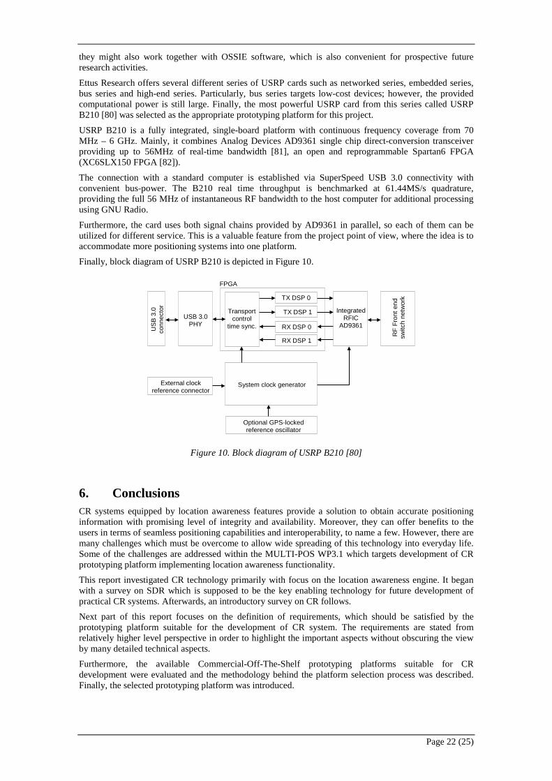
Ettus Research offers several different series of USRP cards such as networked series, embedded series, bus series and high-end series. Particularly, bus series targets low-cost devices; however, the provided computational power is still large. Finally, the most powerful USRP card from this series called USRP B210 [80] was selected as the appropriate prototyping platform for this project.
USRP B210 is a fully integrated, single-board platform with continuous frequency coverage from 70 MHz – 6 GHz. Mainly, it combines Analog Devices AD9361 single chip direct-conversion transceiver providing up to 56MHz of real-time bandwidth [81], an open and reprogrammable Spartan6 FPGA (XC6SLX150 FPGA [82]).
The connection with a standard computer is established via SuperSpeed USB 3.0 connectivity with convenient bus-power. The B210 real time throughput is benchmarked at 61.44MS/s quadrature, providing the full 56 MHz of instantaneous RF bandwidth to the host computer for additional processing using GNU Radio.
Furthermore, the card uses both signal chains provided by AD9361 in parallel, so each of them can be utilized for different service. This is a valuable feature from the project point of view, where the idea is to accommodate more positioning systems into one platform.
Finally, block diagram of USRP B210 is depicted in Figure 10.
Figure 10. Block diagram of USRP B210 [80]
6. Conclusions CR systems equipped by location awareness features provide a solution to obtain accurate positioning information with promising level of integrity and availability. Moreover, they can offer benefits to the users in terms of seamless positioning capabilities and interoperability, to name a few. However, there are many challenges which must be overcome to allow wide spreading of this technology into everyday life. Some of the challenges are addressed within the MULTI-POS WP3.1 which targets development of CR prototyping platform implementing location awareness functionality.
This report investigated CR technology primarily with focus on the location awareness engine. It began with a survey on SDR which is supposed to be the key enabling technology for future development of practical CR systems. Afterwards, an introductory survey on CR follows.
Next part of this report focuses on the definition of requirements, which should be satisfied by the prototyping platform suitable for the development of CR system. The requirements are stated from relatively higher level perspective in order to highlight the important aspects without obscuring the view by many detailed technical aspects.
Furthermore, the available Commercial-Off-The-Shelf prototyping platforms suitable for CR development were evaluated and the methodology behind the platform selection process was described. Finally, the selected prototyping platform was introduced.
US
B 3
.0
conn
ecto
r
Transport control
time sync. Integrated
RFIC AD9361
TX DSP 0
RF
Fron
t end
sw
itch
netw
ork
USB 3.0 PHY
TX DSP 1 RX DSP 0 RX DSP 1
System clock generator
Optional GPS-locked reference oscillator
External clock reference connector
FPGA
Page 23 (25)
7. References [1] J. Mitola, “Software radios-survey, critical evaluation and future directions,” in [Proceedings] NTC-92: National Telesystems Conference,
1992, pp. 13/15–13/23.
[2] Space Systems Technology Group; Garland Division, “New Research Lab Leads to Unique Radio Receiver,” 1985. [Online]. Available: http://chordite.com/team.pdf. [Accessed: 03-May-2014].
[4] R. Farrell, M. Sanchez, and G. Corley, “Software-Defined Radio Demonstrators: An Example and Future Trends,” Int. J. Digit. Multimed. Broadcast., vol. 2009, pp. 1–12, 2009.
[5] Federal Communications Commission, “Tech Topic 4: Software Defined Radio.” [Online]. Available: http://transition.fcc.gov/pshs/techtopics/techtopics4.html. [Accessed: 03-May-2014].
[6] SDR Forum, “Cognitive Radio Definitions and Nomenclature.” [Online]. Available: http://www.sdrforum.org/pages/documentLibrary/documents/SDRF-06-P-0009-V1_0_0_CRWG_Defs.pdf. [Accessed: 03-May-2014].
[7] E. Grayver, “Standardization efforts for software-defined radio,” in 2010 IEEE Aerospace Conference, 2010, pp. 1–8.
[8] T. A. Sturman, “An Evaluation of SDR - An Overview,” 2006.
[9] Federal Communications Commission, “Topic 5: Issues of Software Defined Radio Implementations for Public Safety.” [Online]. Available: http://transition.fcc.gov/pshs/techtopics/techtopic5.html. [Accessed: 03-May-2014].
[10] H. A. Wheeler, “Fundamental Limitations of Small Antennas,” Proc. IRE, vol. 35, no. 12, pp. 1479–1484, Dec. 1947.
[11] J. H. Reed, Software Radio: A Modern Approach to Radio Engineering. Prentice Hall Professional, 2002, p. 567.
[12] T. Neu, “Clock jitter analyzed in the time domain, Part 1.” [Online]. Available: http://www.ti.com/lit/an/slyt379/slyt379.pdf. [Accessed: 03-May-2014].
[14] P. Poshala, “Why Oversample when Undersampling can do the Job?,” no. July, 2013.
[15] H. Arslan, Cognitive Radio, Software Defined Radio, and Adaptive Wireless Systems (Google eBook). Springer, 2007, p. 488.
[16] A. Loke and F. Ali, “Direct conversion radio for digital mobile phones-design issues, status, and trends,” IEEE Trans. Microw. Theory Tech., vol. 50, no. 11, pp. 2422–2435, Nov. 2002.
[17] M. Trinkle, “Dynamic range considerations for wideband Zero-IF receivers,” in 2009 4th IEEE Conference on Industrial Electronics and Applications, 2009, pp. 1976–1981.
[18] G. Kalivas, Digital Radio System Design (Google eBook). John Wiley & Sons, 2009, p. 472.
[19] R. P. Martins, “A low-IF/zero-IF reconfigurable receiver with two-step channel selection technique for multistandard applications,” in 2004 IEEE International Symposium on Circuits and Systems (IEEE Cat. No.04CH37512), 2004, vol. 4, pp. IV–417–20.
[20] C. de la Morena-Alvarez-Palencia and B.-G. M., “Experimental performance comparison of six-port and conventional zero-if/low-if receivers for software defined radio.” [Online]. Available: http://www.jpier.org/PIERB/pierb42/15.12061210.pdf. [Accessed: 03-May-2014].
[21] Maxim Integrated, “MAX2830 2.4GHz to 2.5GHz 802.11g/b RF Transceiver with PA and Rx/Tx/Diversity Switch.” [Online]. Available: http://www.maximintegrated.com/en/products/comms/wireless-rf/MAX2830.html. [Accessed: 03-May-2014].
[23] Analog Devices, “ADF7242 datasheet.” [Online]. Available: http://www.analog.com/en/rfif-components/rfif-transceivers/adf7242/products/product.html. [Accessed: 03-May-2014].
[24] S. B. Cohn and N. P. Weinhouse, “An automatic microwave phase measurement system,” Microw. J., vol. 7, pp. 49–56, 1964.
[25] R. G. Bosisio, “A six-port direct digital millimeter wave receiver,” in Proceedings of IEEE National Telesystems Conference - NTC ’94, 1994, pp. 79–82.
[26] T. Hentschel, “The six-port as a communications receiver,” IEEE Trans. Microw. Theory Tech., vol. 53, no. 3, pp. 1039–1047, Mar. 2005.
[27] C. de la Morena-Alvarez-Palencia, M. Burgos-Garcıa, and J. Gismero-Menoyo, “Miniaturized 0.3–6 GHz LTCC six-port receiver for software defined radio.” [Online]. Available: http://www.jpier.org/PIER/pier142/35.13070806.pdf. [Accessed: 03-May-2014].
[28] E. Grayver, Implementing Software Defined Radio (Google eBook). Springer, 2012, p. 285.
[29] U. Ramacher, “Software-Defined Radio Prospects for Multistandard Mobile Phones,” Computer (Long. Beach. Calif)., vol. 40, no. 10, pp. 62–69, Oct. 2007.
[30] O. Anjum, T. Ahonen, F. Garzia, J. Nurmi, C. Brunelli, and H. Berg, “State of the art baseband DSP platforms for Software Defined Radio: A survey,” EURASIP J. Wirel. Commun. Netw., vol. 2011, no. 1, p. 5, Jun. 2011.
[31] T. Ulversoy, “Software Defined Radio: Challenges and Opportunities,” IEEE Commun. Surv. Tutorials, vol. 12, no. 4, pp. 531–550, 2010.
[32] R. C. Reinhart, S. K. Johnson, T. J. Kacpura, C. S. Hall, C. R. Smith, and J. Liebetreu, “Open Architecture Standard for NASA’s Software-Defined Space Telecommunications Radio Systems,” Proc. IEEE, vol. 95, no. 10, pp. 1986–1993, Oct. 2007.
[33] D. Symeonidis and G. Baldini, “European Standardization and SDR Certification,” in 2010 Sixth Advanced International Conference on Telecommunications, 2010, pp. 136–141.
[34] C. R. Aguayo Gonzalez, C. B. Dietrich, and J. H. Reed, “Understanding the software communications architecture,” IEEE Commun. Mag., vol. 47, no. 9, pp. 50–57, Sep. 2009.
[35] Joint Tactical Networking Center, “Software communications architecture specification,” 2012.
[43] S. Usman, A. Mahmood, and M. R. Ashraf, “Porting of OSSIE on Texas Instrument’s DAVINCI SoC Based SDR Platform,” in 2012 International Conference on Cyber-Enabled Distributed Computing and Knowledge Discovery, 2012, pp. 304–308.
[44] GNU Radio, “GNU Radio.” [Online]. Available: http://gnuradio.org/redmine/projects/gnuradio/wiki. [Accessed: 03-May-2014].
[45] W. Plishker, G. F. Zaki, S. S. Bhattacharyya, C. Clancy, and J. Kuykendall, “Applying graphics processor acceleration in a software defined radio prototyping environment,” in 2011 22nd IEEE International Symposium on Rapid System Prototyping, 2011, pp. 67–73.
[46] “Ettus Research - USRP.” [Online]. Available: http://home.ettus.com/. [Accessed: 03-May-2014].
[47] J.-P. D. Gael Abgrall, “A comparative study of two software defined radio platforms.”
[48] I. ComSoc, “Best Readings in Cognitive Radio | IEEE Communications Society.” [Online]. Available: http://www.comsoc.org/best-readings/cognitive-radio. [Accessed: 03-May-2014].
[49] J. Mitola and G. Q. Maguire, “Cognitive radio: making software radios more personal,” IEEE Pers. Commun., vol. 6, no. 4, pp. 13–18, 1999.
[50] ITU-R, “Definitions of Software Defined Radio (SDR) and Cognitive Radio System (CRS),” SM Series Spectrum management, 2009. [Online]. Available: http://www.itu.int/dms_pub/itu-r/opb/rep/R-REP-SM.2152-2009-PDF-E.pdf. [Accessed: 03-May-2014].
[51] A. Masucci and M. Debbah, “Non-commutative large entries for cognitive radio applications,” EURASIP J. Wirel. Commun. Netw., vol. 2012, no. 1, p. 167, May 2012.
[52] “Cognition in Encyclopedia Britannica.” [Online]. Available: http://global.britannica.com/EBchecked/topic/124474/cognition. [Accessed: 03-May-2014].
[53] G. F. Luger, Cognitive Science: the science of intelligent systems. Academic Press, 1999.
[54] A. Amanna and J. H. Reed, “Survey of cognitive radio architectures,” in Proceedings of the IEEE SoutheastCon 2010 (SoutheastCon), 2010, pp. 292–297.
[55] S. Haykin, “Cognitive radio: brain-empowered wireless communications,” IEEE J. Sel. Areas Commun., vol. 23, no. 2, pp. 201–220, Feb. 2005.
[56] K. Patil, R. Prasad, and K. Skouby, “A Survey of Worldwide Spectrum Occupancy Measurement Campaigns for Cognitive Radio,” in 2011 International Conference on Devices and Communications (ICDeCom), 2011, pp. 1–5.
[57] V. Valenta, R. Mars ̌álek, G. Baudoin, M. Villegas, M. Suarez, and F. Robert, “Survey on spectrum utilization in Europe: Measurements, analyses and observations.” pp. 1–5, 2010.
[58] L. Doyle, Essentials of Cognitive Radio. Cambridge University Press, 2009, p. 234.
[59] E. Axell, G. Leus, E. Larsson, and H. Poor, “Spectrum Sensing for Cognitive Radio : State-of-the-Art and Recent Advances,” IEEE Signal Process. Mag., vol. 29, no. 3, pp. 101–116, May 2012.
[60] A. B. MacKenzie, J. H. Reed, P. Athanas, C. W. Bostian, R. M. Buehrer, L. A. DaSilva, S. W. Ellingson, Y. T. Hou, M. Hsiao, C. Patterson, S. Raman, and C. da Silva, “Cognitive Radio and Networking Research at Virginia Tech,” Proc. IEEE, vol. 97, no. 4, pp. 660–688, Apr. 2009.
[61] W. Jouini, C. Moy, and J. Palicot, “Decision making for cognitive radio equipment: analysis of the first 10 years of exploration,” EURASIP J. Wirel. Commun. Netw., vol. 2012, no. 1, p. 26, Jan. 2012.
[62] R. Thomas, D. Friend, L. Dasilva, and A. Mackenzie, “Cognitive networks: adaptation and learning to achieve end-to-end performance objectives,” IEEE Commun. Mag., vol. 44, no. 12, pp. 51–57, Dec. 2006.
[63] G. Kramer, M. Gastpar, and P. Gupta, “Cooperative Strategies and Capacity Theorems for Relay Networks,” IEEE Trans. Inf. Theory, vol. 51, no. 9, pp. 3037–3063, Sep. 2005.
[64] K. Ben Letaief, “Cooperative Communications for Cognitive Radio Networks,” Proc. IEEE, vol. 97, no. 5, pp. 878–893, May 2009.
[65] J. M. III., Cognitive Radio Architecture: The Engineering Foundations of Radio XML. John Wiley & Sons. 2006.
[66] J. Palicot, J. Mitola, Z. Lei, and F. K. Jondral, “Special issue on 10 years of cognitive radio: state-of-the-art and perspectives,” EURASIP J. Wirel. Commun. Netw., vol. 2012, no. 1, p. 214, Jul. 2012.
[67] H. Celebi, “Location awareness in cognitive radio networks,” 2008. [Online]. Available: http://scholarcommons.usf.edu/cgi/viewcontent.cgi?article=1166&context=etd. [Accessed: 03-May-2014].
[68] “IEEE 802.22 Working Group on Wireless Regional Area Networks.” [Online]. Available: http://www.ieee802.org/22/.
[69] H. Wymeersch, J. Lien, and M. Z. Win, “Cooperative Localization in Wireless Networks,” Proc. IEEE, vol. 97, no. 2, pp. 427–450, Feb. 2009.
[70] H. Celebi and H. Arslan, “Cognitive Positioning Systems,” IEEE Trans. Wirel. Commun., vol. 6, no. 12, pp. 4475–4483, Dec. 2007.
[71] M. Narkus-Kramer, W. Scales, and E. Calle, “Evaluating eLORAN as a backup for surveillance and navigation: A comparative cost analysis,” in 2009 IEEE/AIAA 28th Digital Avionics Systems Conference, 2009, pp. 4.D.1–1–4.D.1–6.
[72] M. Dardaillon, K. Marquet, T. Risset, and A. Scherrer, “Software defined radio architecture survey for cognitive testbeds,” in 2012 8th International Wireless Communications and Mobile Computing Conference (IWCMC), 2012, pp. 189–194.
[73] “List of software-defined radios - Wikipedia, the free encyclopedia.” [Online]. Available: http://en.wikipedia.org/wiki/List_of_software-defined_radios. [Accessed: 03-May-2014].