Technical Service Bulletin Bulletin #: CMP-2006-001 Date: 28/03/06 Product: Compressor Generator Tools Subject: Cummins QSL9 Tier III engine technical overview Models 9/270, 9/300, 12/235, 17/235, 21/215 The QSL9 with CM850 engine is designed to meet the Environmental Protection Agency (EPA) Tier III levels.
Transcript
Technical Service Bulletin
Bulletin #: CMP-2006-001 Date: 28/03/06
Product: Compressor Generator Tools
Subject: Cummins QSL9 Tier III engine technical overview
Models 9/270, 9/300, 12/235, 17/235, 21/215
The QSL9 with CM850 engine is designed to meet the Environmental Protection Agency (EPA) Tier III levels.
The engine data plate provides important facts about the engine. The engine serial number (ESN) and control parts list (CPL) provide information for service and ordering parts. The engine data plate must not be changed unless approved by Cummins Inc.
The data plate is located on the top side of the gear housing.
If the engine data plate (1) is not readable, the ESN (2) can be found on the engine block on top of the lubricating oil cooler housing. Additional engine information is on the electronic control module (ECM) data plate.
Page 3 of 17
Technical Service Bulletin
ECM Dataplate
The ECM dataplate is located on the front of the ECM. The following information is found on the ECM dataplate:
• ECM part number (PN) • ECM serial number (SN) • ECM date code (DC) • Engine serial number (ESN) • ECM Code (identifies the software in the ECM).
Product Release Timing
The full production release of the QSL9 with CM850 control module engine began January 2005.
Page 4 of 17
Technical Service Bulletin Design Features
Cylinder Block – Overview
The QSL9 with CM850 utilizes different connecting rod bearings for the upper and lower bearing shells. The upper bearing is a higher-grade material to withstand increased forces due to higher cylinder pressures. This bearing is also narrower to accommodate crankshaft fillet radii changes. The lower bearing on the QSL9 with CM850 is a lower-grade material compared to the upper bearing and will fail if installed in the upper bearing shell. The upper and lower bearings are marked “UPR” and “LWR”, respectively, for identification purposes.
On the QSL9 with CM850, the connecting rod design continues to be an angle-split rod; however, the surface between the connecting rod and the cap is no longer machined. This is a fracture-split rod meaning the cap is separated utilizing a high momentum impact, resulting in a unique surface on every connecting rod cap. The surface of the connecting rod and cap must be protected against damage; the cap and rod must be reassembled before performing any cleaning. Any damage to the fractured surface will result in an improper torque on the connecting rod cap screws.
The QSL9 with CM850 engine is equipped with J-jet directed piston cooling nozzles. The nozzle geometry is similar to the ISL with CM554 with slight changes to the oil spray targeting for improved cooling of the piston. A standard cap screw secures the piston cooling nozzle, replacing a banjo style bolt for added strength and oil flow.
Page 5 of 17
Technical Service Bulletin
The primary speed indicator ring has been moved internally and mounted to the crankshaft. The new indicator ring provides increased speed resolution for the Cummins Common Rail Fuel System. To calculate the engine speed and position, a sensor is mounted at the rear of the block on the intake side of the engine.
The secondary (backup) indicator pick-ups are cast into the camshaft gear. The secondary sensor is located in the backside of the gear housing.
Due to geometrical differences, the primary and secondary speed sensors are not interchangeable and have different part numbers.
Page 6 of 17
Technical Service Bulletin
Rocker Levers – Overview
The crankcase breather system utilizes a baffle system that is mounted on the valve cover. The breather contains two tubes. The larger tube is the crankcase gas draft tube. The smaller tube is for draining oil that is accumulated in the valve cover baffle. The oil is drained back to the oil pan through a port on the lower intake-side of the cylinder block. There is no maintenance required for any breather system components.
A rocker housing spacer is required on the QSL9 engine to accommodate a pass-through location for the injector wiring harness. The rocker housing utilizes a press-in-place gasket to form a seal with the cylinder head. The valve cover is mounted to the rocker housing by cap screws, isolators, and a press-in-place gasket.
Page 7 of 17
Technical Service Bulletin Camshaft Followers/Tappets – Overview
The QSL9 with CM850 engine is equipped with new roller tappets. The new design incorporates larger diameter rollers to reduce the load on the camshaft and improve durability. The larger diameter tappets are not backwards compatible to ISL and QSL9 with CM554 tappets.
Fuel System – Overview
General Fuel System Notices
WARNING
Fuel is flammable. Keep all cigarettes, flames, pilot lights, arcing equipment, and switches out of the work area and areas sharing ventilation to reduce the possibility of severe personal injury or death when working on the fuel system.
CAUTION
To reduce the possibility of engine damage, always use the proper torque on the high-pressure line nuts.
The Cummins Common Rail Fuel System is a high-pressure common rail injection system. A fuel rail is used to store pressurized fuel for fuel injection. There are four components that provide or receive input to the electronic control module (ECM). The ECM powers the electric fuel lift pump (located behind the ECM) for approximately 30 seconds at key-on to make sure the fuel system is primed. The normally open fuel pump actuator receives a pulse width modulated (PWM) signal from the ECM to open or close in response to the signal from the fuel rail pressure sensor. The injectors have individual solenoids. The ECM powers each injector individually to provide fueling to each cylinder.
Page 8 of 17
Technical Service Bulletin
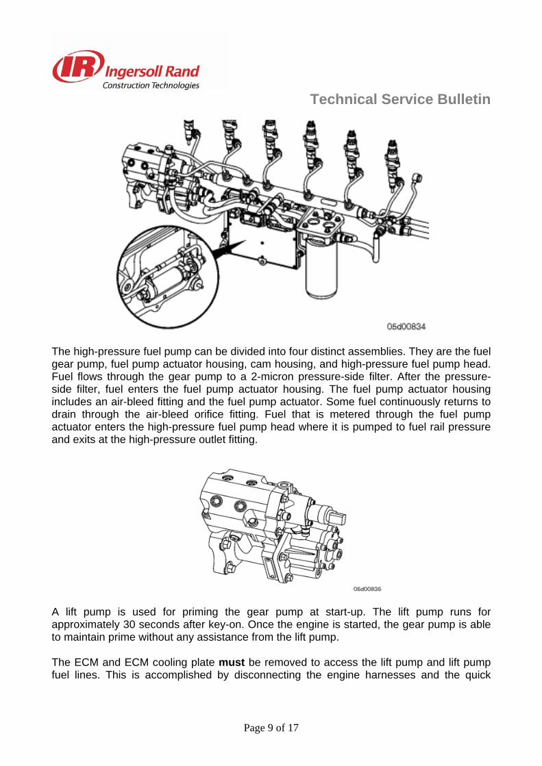
The high-pressure fuel pump can be divided into four distinct assemblies. They are the fuel gear pump, fuel pump actuator housing, cam housing, and high-pressure fuel pump head. Fuel flows through the gear pump to a 2-micron pressure-side filter. After the pressure-side filter, fuel enters the fuel pump actuator housing. The fuel pump actuator housing includes an air-bleed fitting and the fuel pump actuator. Some fuel continuously returns to drain through the air-bleed orifice fitting. Fuel that is metered through the fuel pump actuator enters the high-pressure fuel pump head where it is pumped to fuel rail pressure and exits at the high-pressure outlet fitting.
A lift pump is used for priming the gear pump at start-up. The lift pump runs for approximately 30 seconds after key-on. Once the engine is started, the gear pump is able to maintain prime without any assistance from the lift pump.
The ECM and ECM cooling plate must be removed to access the lift pump and lift pump fuel lines. This is accomplished by disconnecting the engine harnesses and the quick
Page 9 of 17
Technical Service Bulletin disconnect style fuel lines first. Removal of the ECM cooling plate cap screws allows the ECM, cooling plate, lift pump and lift pump plumbing to be removed as one assembly.
The gear pump output is routed to a 2-micron fuel filter. The filtered fuel returns to the fuel pump actuator housing. The high-pressure pump is driven by the engine camshaft. The gear pump is driven by the pump camshaft through an internal coupling.
Each of the two pumping plungers is driven by a three lobed camshaft. The camshaft is located in the cam housing module by tapered roller bearings. The bearings that support the camshaft, as well as the tappets, rollers and camshaft itself are lubricated with engine oil. These are the only components in the pump lubricated with engine oil.
Page 10 of 17
Technical Service Bulletin Engine oil to the high-pressure pump is supplied through a drilling in the engine gear housing. The oil passes from the engine gear housing to the high-pressure pump cam housing. A small o-ring in a recess on the back of the engine gear housing seals this passage.
Pressurized fuel from the gear pump is supplied to the fuel pump actuator. The fuel pump actuator is opened or closed by the ECM to maintain the appropriate fuel rail pressure.
An air-bleed orifice fitting in the fuel pump actuator housing aids in purging air from the fuel supply. Because of the air-bleed orifice fitting, some fuel that is supplied by the gear pump will return to drain at all times.
Fuel that is metered past the fuel pump actuator enters the high-pressure fuel pump inlet drilling, past the inlet check valve and fills the pumping chamber by pressing the pumping plunger downward. When the camshaft pushes the pumping plunger upward, fuel reaches rail pressure and causes the outlet check valve to lift. Fuel then enters the outlet drilling of the fuel pump and exits the high pressure fuel line to the fuel rail.
Page 11 of 17
Technical Service Bulletin
Fuel Injection Pump Data plate
The Cummins Common Rail Fuel System data plate is located on the side of the high-pressure pump. The data plate contains the following information:
A. Cummins part number B. Pump serial number
C. Factory code.
Page 12 of 17
Technical Service Bulletin Flow Diagram, Fuel System
1. Fuel from supply tank 2. Fuel filter and water separator 3. OEM fuel supply connection 4. Fuel supply to ECM mounted fuel lift pump 5. ECM cooling plate 6. ECM mounted fuel lift pump 7. Fuel outlet from ECM mounted fuel lift pump 8. Fuel gear pump 9. Fuel from gear pump to fuel filter 10. Primary fuel filter 11. Fuel inlet to fuel pump actuator 12. High-pressure fuel pump 13. Fuel outlet from high-pressure pump 14. High-pressure pump drain flow connection 15. Fuel rail 16. High-pressure injector supply lines 17. High-pressure fuel connector 18. Fuel injector 19. Fuel pressure relief valve 20. Fuel injector drain flow line 21. Fuel return to supply tanks
Page 13 of 17
Technical Service Bulletin Injectors and Fuel Lines – Overview
WARNING
Fuel is flammable. Keep all cigarettes, flames, pilot lights, arcing equipment, and switches out of the work area and areas sharing ventilation to reduce the possibility of severe personal injury or death when working on the fuel system.
High-pressure common rail fuel systems use solenoid-actuated injectors. High-pressure fuel flows into the side of the injector. When the solenoid is activated, an internal needle lifts and fuel is injected. The clearances in the nozzle bore are extremely small and any dirt or contaminants will cause the injector to stick. This is why it is important to clean around all fuel connections before servicing the fuel system. Also, cap or cover any open fuel connections before a fuel system repair is performed.
High-pressure fuel is supplied to the injector from the fuel rail by an injector supply line and a fuel connector. The fuel connector pushes against the injector body when the fuel connector nut is tightened. The injector supply line is then connected to the fuel connector.
CAUTION
To reduce the possibility of engine damage, always use the proper torque on the high-pressure line nuts.
The torque and sequence for this joint is critical. If the nut or line is under-tightened, the surfaces will not seal and a high-pressure fuel leak will result. If the nut is over-tightened, the connector and injector will deform and cause a high-pressure fuel leak. This leak will be inside the head and will not be visible. The result will be a fault code, low power, or no-start.
If the injector is not fully seated prior to the installation of the high-pressure connector, the joint will not seal.
The fuel connector contains an edge filter that breaks up small contaminants that enter the fuel system.
The edge filters are not a substitute for cleaning and covering all fuel system connections during repair.
Be sure to cap or cover all fuel fittings and ports.
All injectors feed into a common return drilling contained within the cylinder head. Any excess fuel is returned to the tank via this drilling and return line attached to the rear of the cylinder head. A back-pressure valve is located on the back of the cylinder head where the drain line attaches.
Page 14 of 17
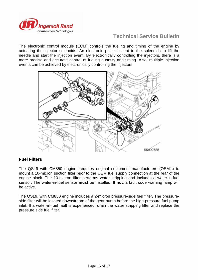
Technical Service Bulletin The electronic control module (ECM) controls the fueling and timing of the engine by actuating the injector solenoids. An electronic pulse is sent to the solenoids to lift the needle and start the injection event. By electronically controlling the injectors, there is a more precise and accurate control of fueling quantity and timing. Also, multiple injection events can be achieved by electronically controlling the injectors.
Fuel Filters
The QSL9 with CM850 engine, requires original equipment manufacturers (OEM's) to mount a 10-micron suction filter prior to the OEM fuel supply connection at the rear of the engine block. The 10-micron filter performs water stripping and includes a water-in-fuel sensor. The water-in-fuel sensor must be installed. If not, a fault code warning lamp will be active.
The QSL9, with CM850 engine includes a 2-micron pressure-side fuel filter. The pressure-side filter will be located downstream of the gear pump before the high-pressure fuel pump inlet. If a water-in-fuel fault is experienced, drain the water stripping filter and replace the pressure side fuel filter.
Page 15 of 17
Technical Service Bulletin Air Intake System – Overview
The QSL9 engine utilizes a Holset® waste gated turbocharger. The waste gate is pneumatically controlled by intake manifold pressure and factory calibrated. The waste gates are not adjustable in the field.
Electronic Engine Controls – Overview
The electronic control module (ECM) controls all engine operations and is fuel-cooled by a cooling plate. The CM850 module on the QSL9 engine processes all sensor inputs and sends commands to, performs calculations for, and monitors the following:
• Fueling and timing • Turbocharger boost pressure • Operator interface data communications • Auxiliary systems control • Market-specific features.
The CM850 utilizes a 50-pin connector for the OEM harness, a 60-pin connector for the engine harness, and a 4-pin connector for the unswitched power supply harness. The ECM power connector must be directly connected to the vehicle batteries to meet the supply voltage requirements. Several new sensors have been added to monitor and control the new fuel system and turbocharger. The following is a list of sensors on the engine:
INSITE™ electronic service tool Version 6.3, or later, is required for the QSL9 equipped with CM850 electronic control module (ECM).
Page 16 of 17
Technical Service Bulletin
Summary of main differences between QSL9 Tier 2 & QSL9 Tier 3
• New common rail fuel system replaces CAPS • Improved valve cover mounted breather • Fractured split rods used on QSL • Increased capacity lube pump and modified filter head for increased oil flow. • New ECM (CM850) and sensors • Increase number of plates in the oil cooler. • Speed indicator ring moved to the crankshaft. • New main bearing fixings. • ECM cooling plate & electric lift pump • Compressor inlet temperature sensors