TECHNICAL & SERVICE MANUAL CONTENTS 1. TECHNICAL CHANGES ......................... 2 2. SAFETY PRECAUTION .......................... 2 3. PART NAMES AND FUNCTIONS .......... 6 4. SPECIFICATION ..................................... 8 5. OUTLINES AND DIMENSIONS ............ 11 6. WIRING DIAGRAM ............................... 12 7. REFRIGERANT SYSTEM DIAGRAM ........ 13 8. TROUBLESHOOTING .......................... 13 9. DISASSEMBLY PROCEDURE ............. 21 Indoor unit [Model names] [Service Ref.] PKFY-P32VHM-E PKFY-P32VHM-E PKFY-P32VHM-ER1 PKFY-P40VHM-E PKFY-P40VHM-E PKFY-P40VHM-ER1 PKFY-P50VHM-E PKFY-P50VHM-E PKFY-P50VHM-ER1 No. OCH442 REVISED EDITION-A INDOOR UNIT SPLIT-TYPE, HEAT PUMP AIR CONDITIONERS R407C R22 R410A Note: • This manual describes only service data of the indoor units. • RoHS compliant products have <G> mark on the spec name plate. February 2009 PARTS CATALOG (OCB442) Revision: • PKFY-P32/40/50VHM-ER1 are added in REVISED EDITION-A. • Some descriptions have been modified. • Plase void OCH442.
Transcript
TECHNICAL & SERVICE MANUAL
CONTENTS
1. TECHNICAL CHANGES ......................... 22. SAFETY PRECAUTION ..........................23. PART NAMES AND FUNCTIONS .......... 64. SPECIFICATION .....................................85. OUTLINES AND DIMENSIONS ............ 116. WIRING DIAGRAM ...............................127. REFRIGERANT SYSTEM DIAGRAM ........138. TROUBLESHOOTING ..........................139. DISASSEMBLY PROCEDURE .............21
• RoHS compliant products have <G> mark on the spec name plate.
February 2009
PARTS CATALOG (OCB442)
Revision:• PKFY-P32/40/50VHM-ER1
are added in REVISED EDITION-A.
• Some descriptions have been modified.
• Plase void OCH442.
2
2 SAFETY PRECAUTION
[1] Cautions for service · After recovering all the refrigerant in the unit, proceed to working. · Do not release refrigerant in the air. · After completing the repair service, recharge the cycle with the specified amount of liquid refrigerant.
Cautions for units utilizing refrigerant R407C
CAUTIONS RELATED TO NEW REFRIGERANT
Do not use the existing refrigerant piping.
The old refrigerant and lubricant in the existing piping contain a large amount of chlorine which may cause the lubricant deterioration of the new unit.
Use “low residual oil piping”
If there is a large amount of residual oil (hydraulic oil, etc.) inside the piping and joints, deterioration of the lubricant will result.
Use ESTR , ETHER or HAB as the lubricant to coat flares and flange connection parts.If large amount of mineral oil enters, that can cause deterioration of refrigerant oil etc.
Use liquid refrigerant to charge the system.
If gas refrigerant is used to seal the system, the composition of the refrigerant in the cylinder will change and performance may drop.
Do not use a refrigerant other than R407C.
If another refrigerant (R22, etc.) is used, the chlorine in the refrigerant may cause the lubricant deterioration.
Use a vacuum pump with a reverse flow check valve.
The vacuum pump oil may flow back into the refrigerant cycle and cause the lubricant deterioration.
Store the piping to be used indoors during installation and both ends sealed until just before brazing. (Store elbows and other joints in a plastic bag.)
If dust, dirt, or water enters the refrigerant cycle, deterioration of the oil and compressor trouble may result.
Ventilate the room if refrigerant leaks during operation. If refrigerant comes into contact witha flame, poisonous gases will be released.
1. INDOOR CONTROLLER BOARD (I.B.) has been changed. (S/W version up)2. Fan speed has been changed. (4 speed → 3 speed)3. Heat exchanger has been changed.
PKFY-P32VHM-EPKFY-P40VHM-EPKFY-P50VHM-E
Service parts of room temp. thermistor (TH21) has been changed. (T7W E05 202 → R01 N20 202)(The position to be attached has been changed. Band/PVC tube have been added.)
33
[3] Service tools Use the below service tools as exclusive tools for R407C refrigerant.
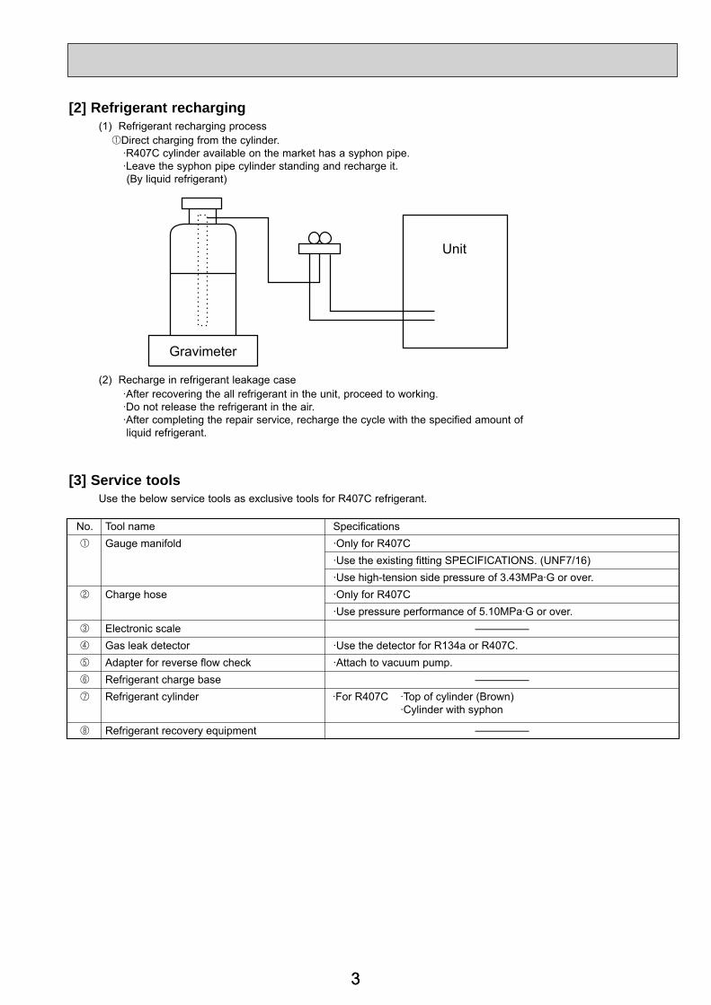
[2] Refrigerant recharging (1) Refrigerant recharging process 1Direct charging from the cylinder. ·R407C cylinder available on the market has a syphon pipe. ·Leave the syphon pipe cylinder standing and recharge it. (By liquid refrigerant)
(2) Recharge in refrigerant leakage case ·After recovering the all refrigerant in the unit, proceed to working. ·Do not release the refrigerant in the air. ·After completing the repair service, recharge the cycle with the specified amount of liquid refrigerant.
Gravimeter
Unit
No. Tool name SpecificationsGauge manifold ·Only for R407C
·Use the existing fitting SPECIFICATIONS. (UNF7/16)·Use high-tension side pressure of 3.43MPa·G or over.
Charge hose ·Only for R407C·Use pressure performance of 5.10MPa·G or over.
—Electronic scaleGas leak detector ·Use the detector for R134a or R407C.Adapter for reverse flow check ·Attach to vacuum pump.
—
—
Refrigerant charge baseRefrigerant cylinder ·For R407C ·Top of cylinder (Brown)
·Cylinder with syphon
Refrigerant recovery equipment
4
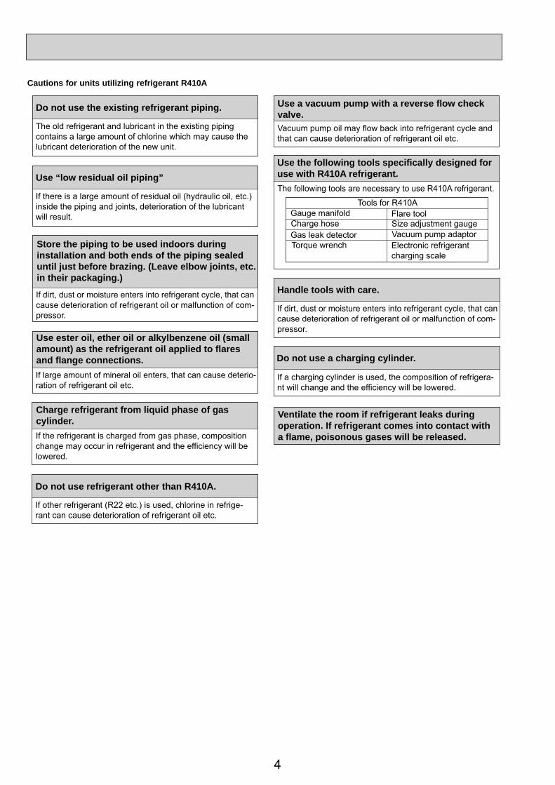
Cautions for units utilizing refrigerant R410A
Store the piping to be used indoors during installation and both ends of the piping sealed until just before brazing. (Leave elbow joints, etc. in their packaging.)
Use ester oil, ether oil or alkylbenzene oil (small amount) as the refrigerant oil applied to flares and flange connections.
Charge refrigerant from liquid phase of gascylinder.If the refrigerant is charged from gas phase, composition change may occur in refrigerant and the efficiency will be lowered.
Do not use refrigerant other than R410A.
If other refrigerant (R22 etc.) is used, chlorine in refrige-rant can cause deterioration of refrigerant oil etc.
Use a vacuum pump with a reverse flow check valve.Vacuum pump oil may flow back into refrigerant cycle and that can cause deterioration of refrigerant oil etc.
Use the following tools specifically designed for use with R410A refrigerant.The following tools are necessary to use R410A refrigerant.
Handle tools with care.
If dirt, dust or moisture enters into refrigerant cycle, that cancause deterioration of refrigerant oil or malfunction of com-pressor.
Do not use a charging cylinder.
If a charging cylinder is used, the composition of refrigera-nt will change and the efficiency will be lowered.
Flare tool
Electronic refrigerant charging scale
Vacuum pump adaptorSize adjustment gauge
Gauge manifold
Torque wrenchGas leak detectorCharge hose
Tools for R410A
If dirt, dust or moisture enters into refrigerant cycle, that cancause deterioration of refrigerant oil or malfunction of com-pressor.
If large amount of mineral oil enters, that can cause deterio-ration of refrigerant oil etc.
Do not use the existing refrigerant piping.
The old refrigerant and lubricant in the existing piping contains a large amount of chlorine which may cause the lubricant deterioration of the new unit.
Use “low residual oil piping”
If there is a large amount of residual oil (hydraulic oil, etc.) inside the piping and joints, deterioration of the lubricant will result.
Ventilate the room if refrigerant leaks during operation. If refrigerant comes into contact witha flame, poisonous gases will be released.
5
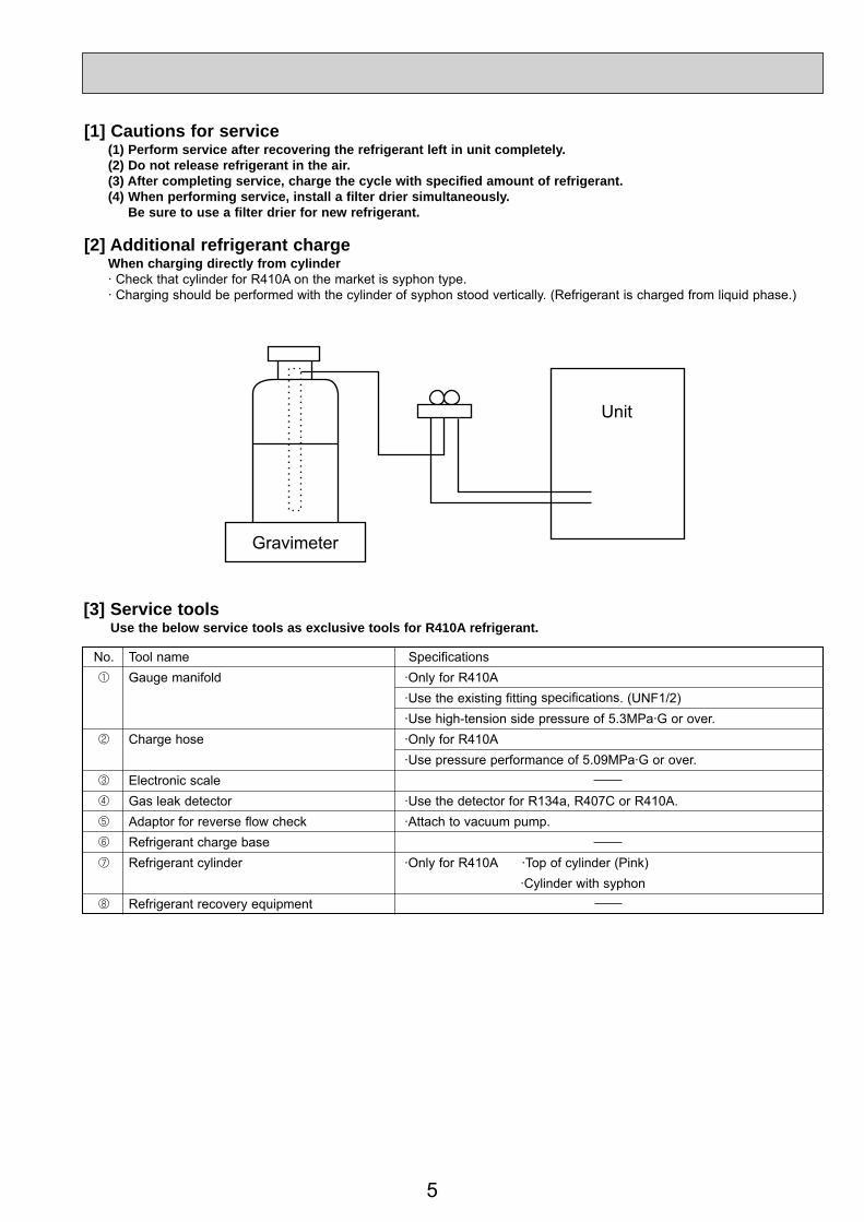
[1] Cautions for service (1) Perform service after recovering the refrigerant left in unit completely. (2) Do not release refrigerant in the air. (3) After completing service, charge the cycle with specified amount of refrigerant. (4) When performing service, install a filter drier simultaneously. Be sure to use a filter drier for new refrigerant.
[2] Additional refrigerant charge When charging directly from cylinder · Check that cylinder for R410A on the market is syphon type. · Charging should be performed with the cylinder of syphon stood vertically. (Refrigerant is charged from liquid phase.)
Gravimeter
Unit
[3] Service tools Use the below service tools as exclusive tools for R410A refrigerant.
No. Tool name Specifications 1 Gauge manifold ·Only for R410A ·Use the existing fitting specifications. (UNF1/2) ·Use high-tension side pressure of 5.3MPa·G or over. 2 Charge hose ·Only for R410A ·Use pressure performance of 5.09MPa·G or over. 3 Electronic scale 4 Gas leak detector ·Use the detector for R134a, R407C or R410A. 5 Adaptor for reverse flow check ·Attach to vacuum pump. 6 Refrigerant charge base 7 Refrigerant cylinder ·Only for R410A ·Top of cylinder (Pink) ·Cylinder with syphon 8 Refrigerant recovery equipment
6
3 PART NAMES AND FUNCTIONS
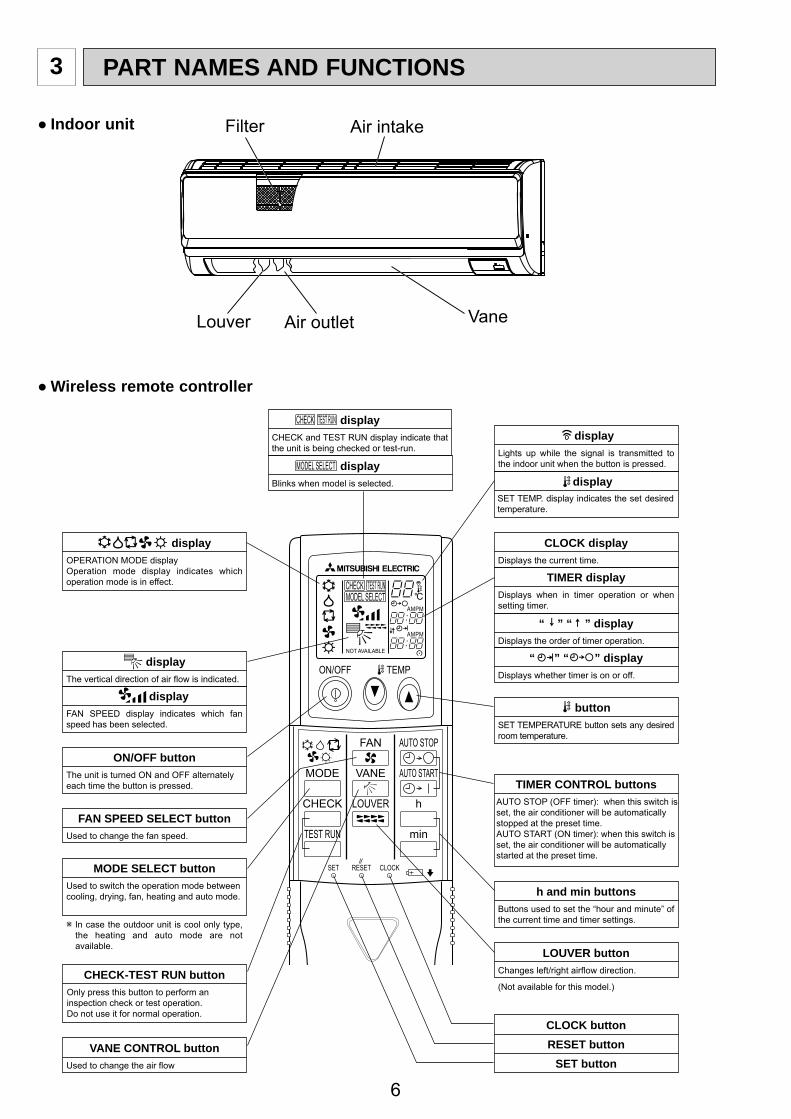
Indoor unit Filter Air intake
Louver Air outlet Vane
Wireless remote controller
ON/OFF TEMP
FAN
VANE
TEST RUN
AUTO STOP
AUTO START
h
min
LOUVER
MODE
CHECK
RESETSET CLOCK
MODEL SELECT
NOT AVAILABLE
CHECK TEST RUN°C
AMPM
AMPM
VANE CONTROL buttonUsed to change the air flow
CLOCK buttonRESET button
SET button
ON/OFF buttonThe unit is turned ON and OFF alternately each time the button is pressed.
MODE SELECT buttonUsed to switch the operation mode between cooling, drying, fan, heating and auto mode.
CHECK-TEST RUN buttonOnly press this button to perform an inspection check or test operation.Do not use it for normal operation.
FAN SPEED SELECT buttonUsed to change the fan speed.
TIMER displayDisplays when in timer operation or when setting timer.
buttonSET TEMPERATURE button sets any desired room temperature.
CLOCK displayDisplays the current time.
“ ” “ ” displayDisplays the order of timer operation.
“ ” “ ” displayDisplays whether timer is on or off.
In case the outdoor unit is cool only type, the heating and auto mode are not available.
Buttons used to set the “hour and minute” of the current time and timer settings.
h and min buttons
display
displayFAN SPEED display indicates which fan speed has been selected.
displayThe vertical direction of air flow is indicated.
displayBlinks when model is selected.
displaydisplay
CHECK and TEST RUN display indicate that the unit is being checked or test-run.
displayOPERATION MODE displayOperation mode display indicates which operation mode is in effect.
TIMER CONTROL buttonsAUTO STOP (OFF timer): when this switch is set, the air conditioner will be automatically stopped at the preset time.AUTO START (ON timer): when this switch is set, the air conditioner will be automatically started at the preset time.
MODEL SELECT
CHECK TEST RUN
SET TEMP. display indicates the set desired temperature.
Lights up while the signal is transmitted to the indoor unit when the button is pressed.
77
°F°C°F°C
ERROR CODEAFTERTIMERTIME SUN MON TUE WED THU FRI SAT
ONOFF
HrAFTER
FILTERFUNCTION
ONLY1Hr.
WEEKLYSIMPLE
AUTO OFF
PAR-21MAA
ON/OFF
FILTER
CHECK
OPERATION CLEAR
TEST
TEMP.
MENU
BACK DAYMONITOR/SET
CLOCK
ON/OFF
●
●
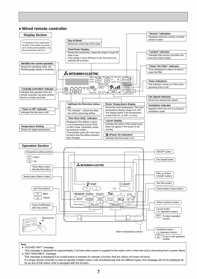
Display Section
For purposes of this explanation,all parts of the display are shownas lit. During actual operation, onlythe relevant items will be lit.
Identifies the current operation Shows the operating mode, etc.*Multilanguage display is available.
“Centrally Controlled” indicatorIndicates that operation from the remote controller has been prohib-ited by a master controller.
“Timer is Off” indicatorIndicates that the timer is off.
Temperature SettingShows the target temperature.
Day-of-WeekShows the current day of the week.
Time/Timer DisplayShows the current time, unless the simple or Auto Offtimer is set.If the simple or Auto Off timer is set, the time to be switched off is shown.
“Sensor” indicationDisplayed when the remote controllersensor is used.
“Locked” indicatorIndicates that remote controller but-tons have been locked.
“Clean The Filter” indicatorTo be displayed on when it is time to clean the filter.
Timer indicatorsThe indicator comes on if the corre-sponding timer is set.
Up/Down Air Direction indica-torThe indicator shows the direc-tion of the outcoming airflow.
“One Hour Only” indicator
Room Temperature displayShows the room temperature. The roomtemperature display range is 8–39 .The display blinks if the temperatureis less than 8 or 39 or more.
Louver displayIndicates the action of the swing louver.Does not appear if the louver is notrunning.
(Power On indicator)Indicates that the power is on.
Fan Speed indicatorShows the selected fan speed.
Ventilation indicatorAppears when the unit is running inVentilation mode.
Operation Section
Temperature setting buttons
Down
Up
Timer Menu button(Monitor/Set button)
Mode button (Return button)
Set Time buttons
Back
Ahead
Timer On/Off button(Set Day button)
Opening thelid
ON/OFF button
Fan Speed button
Filter button(<Enter> button)
Test Run button
Check button (Clear button)
Airflow Up/Down button
Louver button( Operation button)
To return operationnumber
Ventilation button( Operation button)
To go to next operationnumber
Note:“PLEASE WAIT” messageThis message is displayed for approximately 3 minutes when power is supplied to the indoor unit or when the unit is recovering from a power failure.“NOT AVAILABLE” messageThis message is displayed if an invalid button is pressed (to operate a function that the indoor unit does not have).If a single remote controller is used to operate multiple indoor units simultaneously that are different types, this message will not be displayed asfar as any of the indoor units is equipped with the function.
Built-in temperature sensor
Displayed if the airflow is set toLow or downward during COOLor DRY mode. (Operation variesaccording to model.)The indicator goes off in one hour,at which time the airflow direction also changes.
Wired remote controller
8
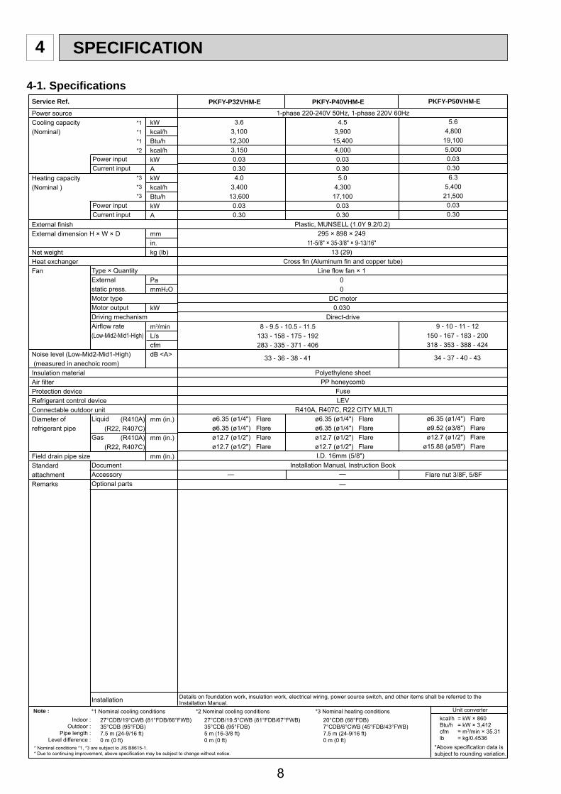
4.53,900
15,4004,0000.030.305.0
4,30017,100
0.030.30
*1 Nominal cooling conditionsNote :Indoor :
Outdoor :Pipe length :
Level difference :
27°CDB/19°CWB (81°FDB/66°FWB)35°CDB (95°FDB)7.5 m (24-9/16 ft)0 m (0 ft)
*2 Nominal cooling conditions27°CDB/19.5°CWB (81°FDB/67°FWB)35°CDB (95°FDB)5 m (16-3/8 ft)0 m (0 ft)
*3 Nominal heating conditions Unit converter
20°CDB (68°FDB)7°CDB/6°CWB (45°FDB/43°FWB)7.5 m (24-9/16 ft)0 m (0 ft)
* Due to continuing improvement, above specification may be subject to change without notice.* Nominal conditions *1, *3 are subject to JIS B8615-1.
NOTES:1. At servicing for outdoor unit,always follow the wiring diagram of outdoor unit.2. In case of using MA-Remote controller, please connect to TB15. (Remote controller wire is non-polar.)3. In case of using M-NET, please connect to TB5. (Transmission line is non-polar.)4. Symbol [S] of TB5 is the shield wire connection.5. Symbols used in wiring diagram above are, : terminal block, :connecter.6. The setting of the SW2 dip switches differs in the capacity. For the detail, refer to the fig. 1.
Mark Meaning Function
Power supply forMA-Remote controller
Main power supply (Indoor unit: 220-240V)Power on → Iamp is lit
LED on indoor board for service
LED1 Main power supply
Power supply for MA-Remote controlleron → Iamp is litLED2
PKFY-P·VHM-ER1Models SW2
P32
P40
P50
123456
ONOFF
123456
ONOFF
123456
ONOFF
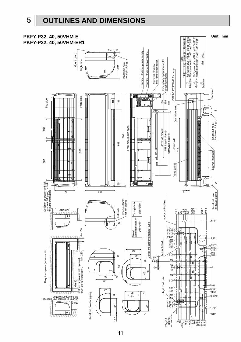
PKFY-P32, 40, 50VHM-EPKFY-P32, 40, 50VHM-ER1
13
TROUBLESHOOTING8
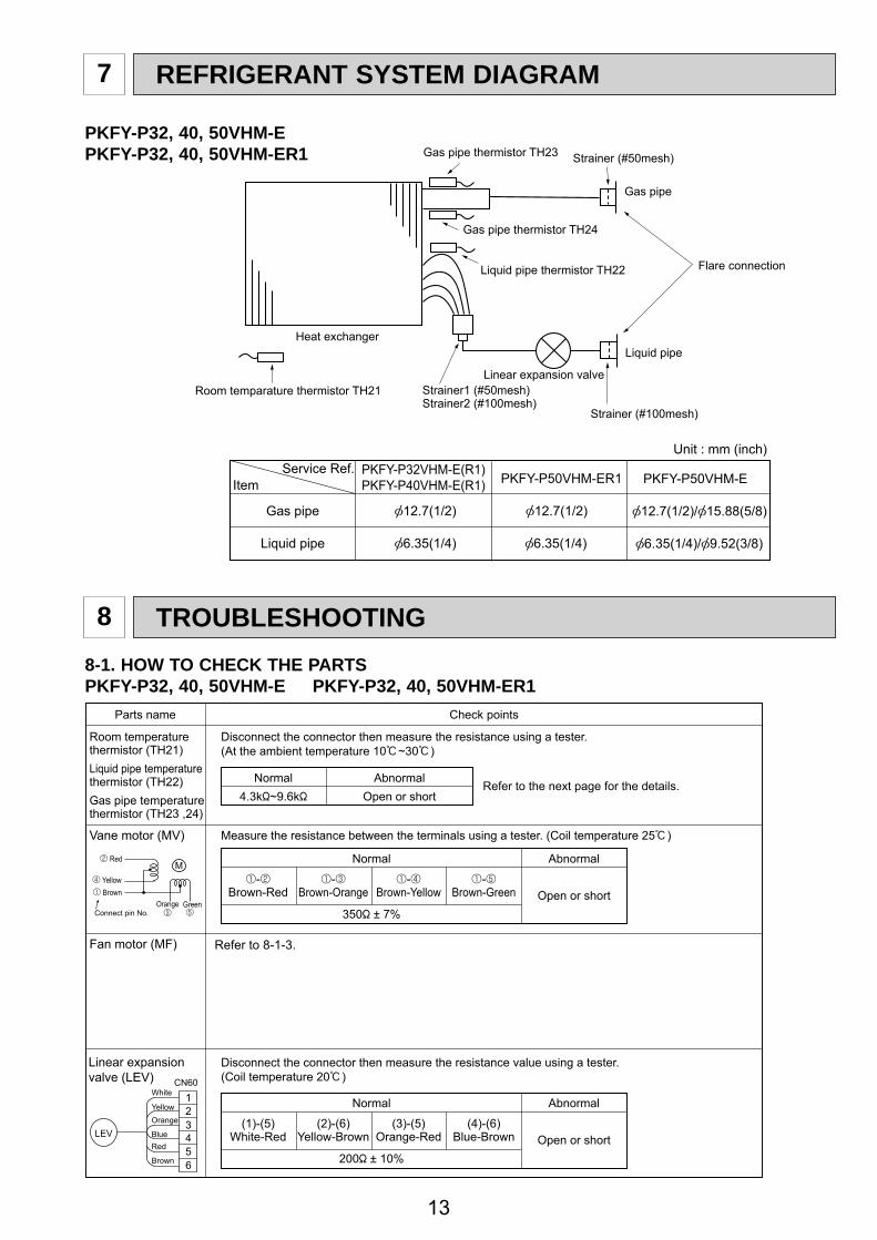
7 REFRIGERANT SYSTEM DIAGRAM
8-1. HOW TO CHECK THE PARTSPKFY-P32, 40, 50VHM-E PKFY-P32, 40, 50VHM-ER1
PKFY-P32, 40, 50VHM-EPKFY-P32, 40, 50VHM-ER1
Parts name Check points
Disconnect the connector then measure the resistance using a tester.(At the ambient temperature 10 ~30 )
Disconnect the connector then measure the resistance value using a tester.(Coil temperature 20 )
1 Operation summary of the linear expansion valve• Linear expansion valve opens/closes through stepping motor after receiving the pulse signal from the indoor controller board.• Valve position can be changed in proportion to the number of pulse signal.<Connection between the indoor controller board and the linear expansion valve>
1273+t
1273
8-1-2. Liner expansion valve
8-1-1. Thermistor
15
Output(Phase)
Output
{11
ON{2 ON{3 OFF{4 OFF
2OFFONONOFF
3OFFOFFONON
4ONOFFOFFON
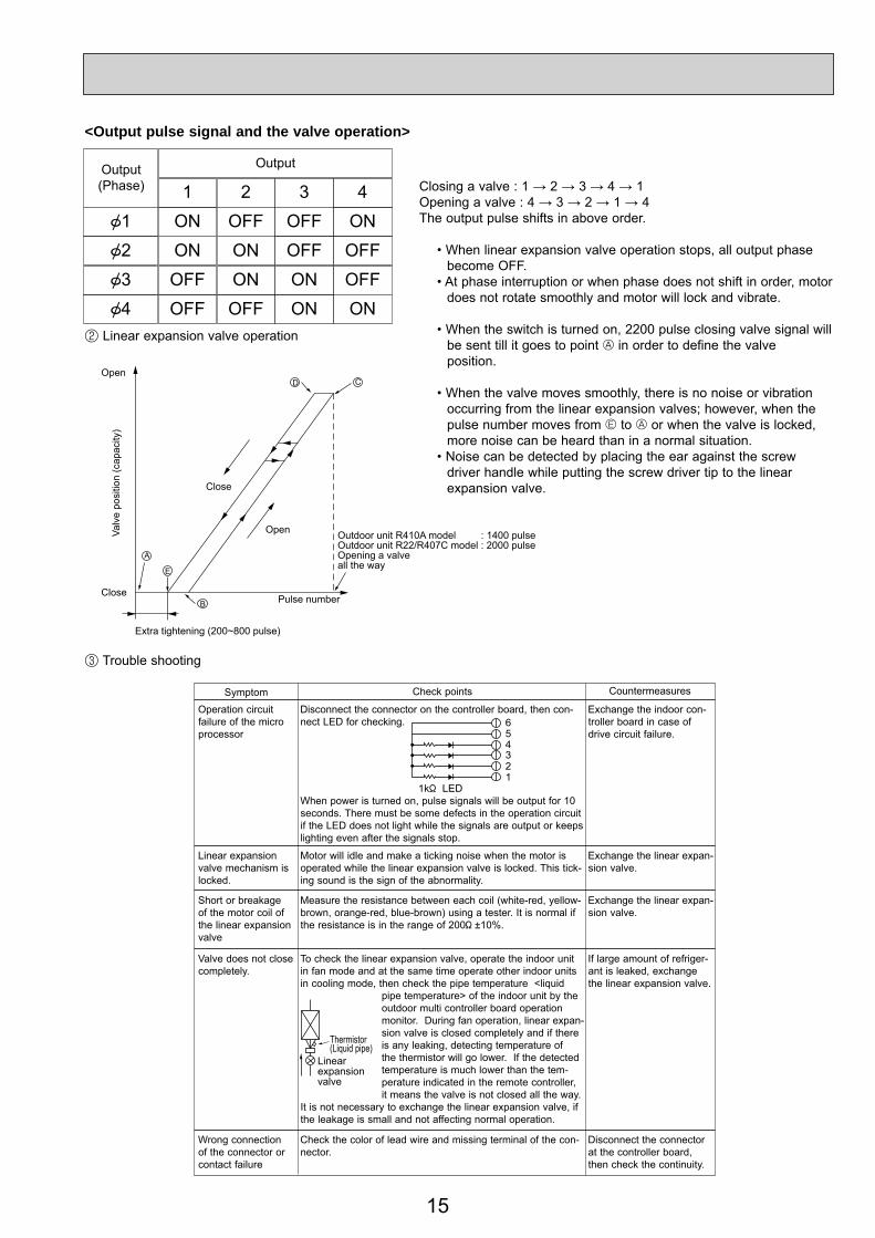
<Output pulse signal and the valve operation>
2 Linear expansion valve operation
3 Trouble shooting
D
A
E
B
C
Open
Open
Extra tightening (200~800 pulse)
Pulse number
Outdoor unit R410A model : 1400 pulseOutdoor unit R22/R407C model : 2000 pulseOpening a valveall the way
• When linear expansion valve operation stops, all output phase become OFF.
• At phase interruption or when phase does not shift in order, motor does not rotate smoothly and motor will lock and vibrate.
• When the switch is turned on, 2200 pulse closing valve signal will be sent till it goes to point A in order to define the valve
position.
• When the valve moves smoothly, there is no noise or vibration occurring from the linear expansion valves; however, when the pulse number moves from E to A or when the valve is locked, more noise can be heard than in a normal situation.
• Noise can be detected by placing the ear against the screw driver handle while putting the screw driver tip to the linear
expansion valve.
654321
LED1k
Symptom Check points
Operation circuit failure of the micro processor
Disconnect the connector on the controller board, then con-nect LED for checking.
When power is turned on, pulse signals will be output for 10 seconds. There must be some defects in the operation circuit if the LED does not light while the signals are output or keeps lighting even after the signals stop.
Countermeasures
Exchange the indoor con-troller board in case of drive circuit failure.
Linear expansion valve mechanism is locked.
Valve does not close completely.
Wrong connection of the connector or contact failure
To check the linear expansion valve, operate the indoor unit in fan mode and at the same time operate other indoor units in cooling mode, then check the pipe temperature <liquid
pipe temperature> of the indoor unit by the outdoor multi controller board operation monitor. During fan operation, linear expan-sion valve is closed completely and if there is any leaking, detecting temperature of the thermistor will go lower. If the detected temperature is much lower than the tem-perature indicated in the remote controller, it means the valve is not closed all the way.
It is not necessary to exchange the linear expansion valve, if the leakage is small and not affecting normal operation.
Thermistor(Liquid pipe)
Linearexpansionvalve
Motor will idle and make a ticking noise when the motor is operated while the linear expansion valve is locked. This tick-ing sound is the sign of the abnormality.
Check the color of lead wire and missing terminal of the con-nector.
Exchange the linear expan-sion valve.
Exchange the linear expan-sion valve.
If large amount of refriger-ant is leaked, exchange the linear expansion valve.
Disconnect the connector at the controller board, then check the continuity.
Measure the resistance between each coil (white-red, yellow-brown, orange-red, blue-brown) using a tester. It is normal if the resistance is in the range of 200 ±10%.
Short or breakage of the motor coil of the linear expansion valve
16
Notes · High voltage is applied to the connecter (CNMF) for the fan motor. Pay attention to the service. · Do not pull out the connector (CNMF) for the motor with the power supply on. (It causes trouble of the indoor controller circuit board and fan motor.)Self checkSymptom : The indoor fan cannot turn around.
Yes
NG
NG
NG
Wiring contact checkContact of fan motor connector (CNMF)
Power supply check (Remove the connector (CNMF))Measure the voltage in the indoor controller circuit board.TEST POINT : VDC (between 1 (+) and 3 (-) of the fan connector): VDC DC310~340VTEST POINT : VCC (between 4 (+) and 3 (-) of the fan connector): VCC DC15V
Wiring recovery
Replace indoor controller board.
Replace indoor controller board.
Replace the fan motor
Replace the fan motor
Indoor controller board fuse check
Replace indoor controller board
Replace the fan motor.
Is the voltage normal?
Is there contact failure?
No
Yes
No
NoIs the fuse normal? Replace the fuse
Yes
Check the operation END
OK
Check the operation END
Check the operation END
OK
Check the operation ENDOK
NG
OK
Check method of DC fan motor (fan motor/indoor controller circuit board)
Sensor signal checkMeasure the voltage between CNMF and DC 0V and DC 15V in the indoor controller circuit board.
Does the voltage repeatDC 0V and DC 15V?
No
Yes
8-1-3. DC Fan motor (fan motor/indoor controller circuit board)
17
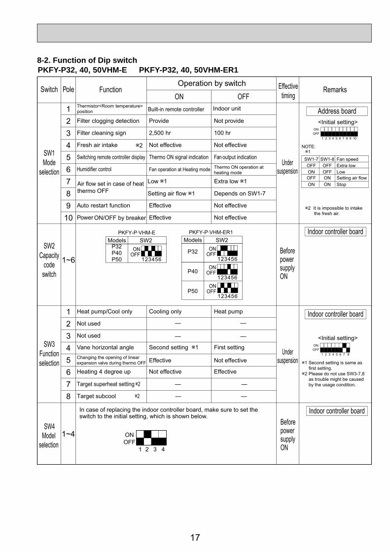
PKFY-P32, 40, 50VHM-E PKFY-P32, 40, 50VHM-ER1
12345678910
1~6
12345678
Thermistor<Room temperature>position
ON OFF
Filter clogging detection Provide Not provide
Filter cleaning sign 2,500 hr 100 hr
Fresh air intake Not effective Not effective
Switching remote controller display Thermo ON signal indication Fan output indication
Humidifier control Fan operation at Heating mode Thermo ON operation atheating mode
Low 1 Extra low 1
Setting air flow 1 Depends on SW1-7
Auto restart function Effective Not effective
Power ON/OFF by breaker Effective Not effective
Heat pump/Cool only Cooling only Heat pump
Not used
Not used
Vane horizontal angle Second setting 1 First setting
Effective Not effective
Heating 4 degree up Not effective Effective
Target superheat setting 2 —
— —
— —
—
Target subcool 2 — —
ONOFF
1 2 3 4 5 6 7 8
ONOFF
1 2 3 4 5 6 7 8 9 10
Address board<Initial setting>
Indoor controller board
<Initial setting> SW3
Functionselection
Undersuspension
SW2Capacity
code
BeforepowersupplyONswitch
SW1Mode
Effectivetiming
Undersuspensionselection
Switch Pole FunctionOperation by switch
Remarks
Built-in remote controller Indoor unit
Changing the opening of linearexpansion valve during thermo OFF
1SW1-7OFFONOFFON
SW1-8OFFOFFONON
Fan speedExtra lowLowSetting air flow Stop
2 It is impossible to intakethe fresh air.
1 Second setting is same asfirst setting.
2 Please do not use SW3-7,8as trouble might be causedby the usage condition.
Air flow set in case of heatthermo OFF
NOTE:2
PKFY-P·VHM-EModels SW2
P32P40P50 123456
ONOFF
PKFY-P·VHM-ER1Models SW2
P32
P40
P50
123456
ONOFF
123456
ONOFF
123456
ONOFF
Indoor controller board
Indoor controller board
1~4 ONOFF
1 2 3 4
SW4Model
selection
In case of replacing the indoor controller board, make sure to set the switch to the initial setting, which is shown below.
BeforepowersupplyON
8-2. Function of Dip switch
18
J41, J42Wirelessremote
controllerPair No.
Jum
per
<Initial setting>Pattern A
Setting pattern
J41 J42
Indoor controller jumper wire Pair No. of wireless
remote controller
Initial settingAB
DC
—Cut
Cut—
——
CutCut
01
32
—
——
Pair No.4-9 of wireless remote controller is setting pattern D.
ON/OFF TEMP
FAN
VANEMODE
CHECK LOUVER
TEST RUN
AUTO STOP
AUTO START
h
min
RESETSET CLOCK
MODEL SELECTModel No.
Temperaturebutton
SET button
Pair No.
Minutebutton
• To operate each indoor unit by each remote controller when installed 2 indoor units or more are near, Pair No. setting is necessary.
Pair No. setting is available with the 4 patterns (Setting patterns A to D)..Make setting for J41, J42 of indoor controller board and the Pair No. of
wireless remote controller.• You may not set it when operating it by one remote controller.
Setting for indoor unitCut jumper wire J41, J42 on the indoor controller board according to the
Setting operation1. Press the SET button (using a pointed implement). Check that the remote controller's display has stopped before continuing.
MODEL SELECT flashes, and the model No. (3 digits) appears (steadily-lit).2. Press the MINUTE button twice. The pair number appears flashing.3. Press the temperature buttons to select the pair number to set.4. Press the SET button (using a pointed implement). The set pair number is displayed (steadily-lit) for 3 seconds, then disappears.
Operation by switchSwitch Remarks
Underoperation
orsuspension
Effectivetiming
0
5
9
4
8 37
2
6
1SW12
10
0
5
9
4
8 37
2
6
1SW11
1
0
8
F
7
E6
D 5C
4
B
3
A
2
9
1
SW14
0
5
9
4
8 37
2
6
1SW12
0
5
9
4
8 37
2
6
1SW11
0
8
F
7
E6
D 5C
4
B
3
A
2
9
1
SW14
Address board
Address board
<Initial setting>
<Initial setting>
SW111s digitaddresssettingSW12
10ths digitaddresssetting
Rot
ary
switc
h
SW14BranchNo.
Setting
Rot
ary
Sw
itch
How to set addressesExample : If address is "3", remain SW12(for over 10) at "0", and match SW11 (for 1 to 9)with "3".
How to set branch numbers SW14 (Series R2 only)Match the indoor unit’s refrigerant pipe with the BC controller’s end connection number.Remain other than series R2 at "0".
Beforepowersupply
ON
19
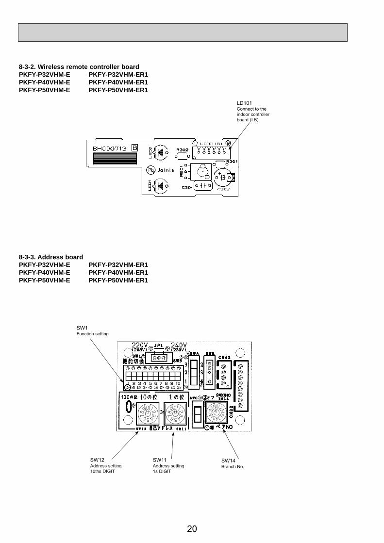
8-3. TEST POINT DIAGRAM8-3-1. Indoor controller board PKFY-P32VHM-E PKFY-P32VHM-ER1PKFY-P40VHM-E PKFY-P40VHM-ER1PKFY-P50VHM-E PKFY-P50VHM-ER1
CN3AConnected to the termial block (TB15)(MA-Remote controller connecting wire)1 - 3 : 8.7-13V DC(Pin1 (+))
CN44Pipe temperature thermistor1-2 : Liquid (TH22)3-4 : Gas1 (TH23)
SW4Model selection
CNDPower supply for indoor controller board1-3 : 220-240AC
SW2Capacity setting
LED1Main power supply(Indoor unit : 220-240V)
CN20Room temperature thermistor (TH21)
LED2Power supply forMA-Remote controller
CN32Remote switch
Jumper wire J41, J42Pair No. setting for wireless remote controller
LDSWE(A)Connect to the wireless remote controller board (S.B)
CN2MConnect to the terminal block (TB5) (M-NET transmission connecting wire)24-30VDC (non-polar)Power supply from outdoor unit
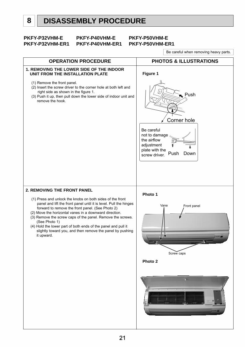
(1) Press and unlock the knobs on both sides of the front panel and lift the front panel until it is level. Pull the hinges forward to remove the front panel. (See Photo 2)(2) Move the horizontal vanes in a downward direction.(3) Remove the screw caps of the panel. Remove the screws. (See Photo 1)(4) Hold the lower part of both ends of the panel and pull it
slightly toward you, and then remove the panel by pushing it upward.
Photo 1
Front panel
Screw caps
Vane
Photo 2
PHOTOSOPERATION PROCEDURE
22
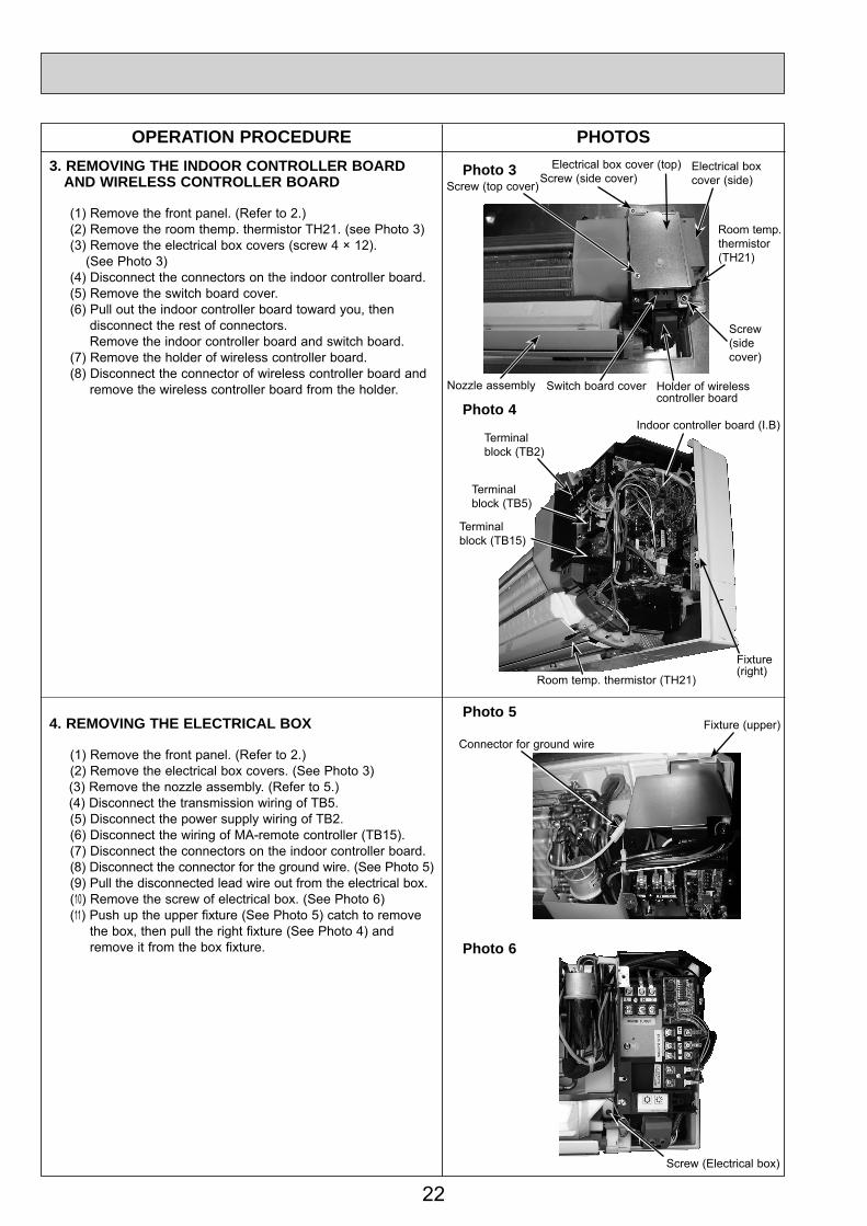
3. REMOVING THE INDOOR CONTROLLER BOARD AND WIRELESS CONTROLLER BOARD
(1) Remove the front panel. (Refer to 2.)(2) Remove the room themp. thermistor TH21. (see Photo 3)(3) Remove the electrical box covers (screw 4 × 12). (See Photo 3)(4) Disconnect the connectors on the indoor controller board.(5) Remove the switch board cover.(6) Pull out the indoor controller board toward you, then disconnect the rest of connectors. Remove the indoor controller board and switch board.(7) Remove the holder of wireless controller board.(8) Disconnect the connector of wireless controller board and remove the wireless controller board from the holder.
Photo 3
Indoor controller board (I.B)
4. REMOVING THE ELECTRICAL BOX
(1) Remove the front panel. (Refer to 2.)(2) Remove the electrical box covers. (See Photo 3)(3) Remove the nozzle assembly. (Refer to 5.)(4) Disconnect the transmission wiring of TB5.(5) Disconnect the power supply wiring of TB2.(6) Disconnect the wiring of MA-remote controller (TB15).(7) Disconnect the connectors on the indoor controller board.(8) Disconnect the connector for the ground wire. (See Photo 5)(9) Pull the disconnected lead wire out from the electrical box.(10) Remove the screw of electrical box. (See Photo 6)(11) Push up the upper fixture (See Photo 5) catch to remove
the box, then pull the right fixture (See Photo 4) and remove it from the box fixture.
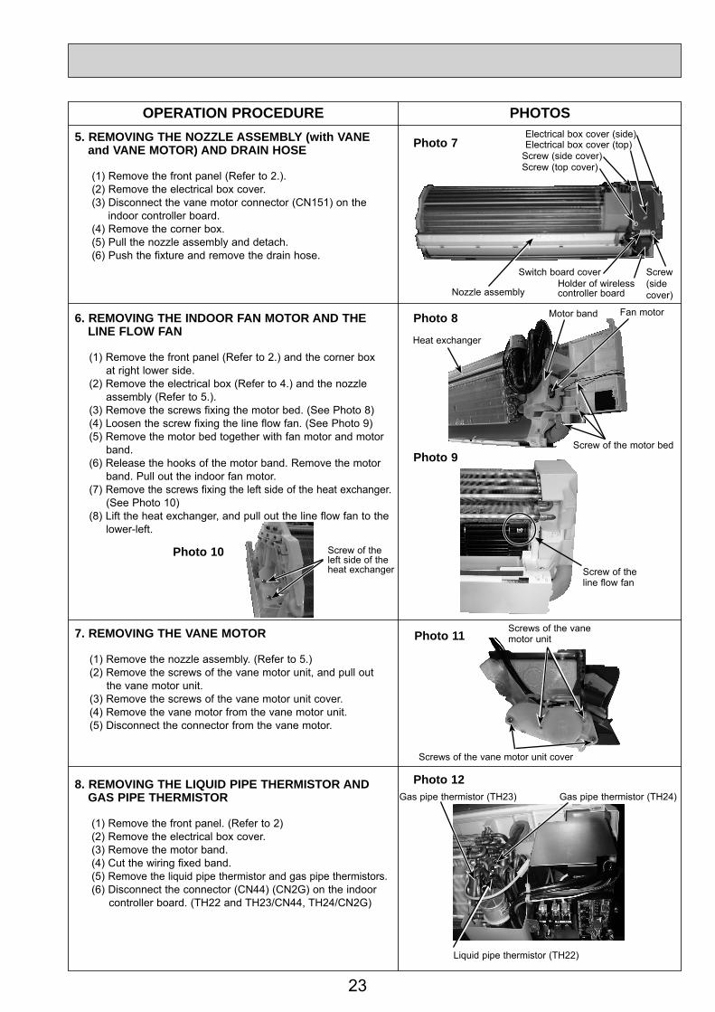
5. REMOVING THE NOZZLE ASSEMBLY (with VANE and VANE MOTOR) AND DRAIN HOSE
(1) Remove the front panel (Refer to 2.).(2) Remove the electrical box cover.(3) Disconnect the vane motor connector (CN151) on the indoor controller board.(4) Remove the corner box.(5) Pull the nozzle assembly and detach.(6) Push the fixture and remove the drain hose.
6. REMOVING THE INDOOR FAN MOTOR AND THE LINE FLOW FAN
(1) Remove the front panel (Refer to 2.) and the corner box at right lower side.(2) Remove the electrical box (Refer to 4.) and the nozzle
assembly (Refer to 5.).(3) Remove the screws fixing the motor bed. (See Photo 8)(4) Loosen the screw fixing the line flow fan. (See Photo 9)(5) Remove the motor bed together with fan motor and motor
band.(6) Release the hooks of the motor band. Remove the motor
band. Pull out the indoor fan motor.(7) Remove the screws fixing the left side of the heat exchanger. (See Photo 10)(8) Lift the heat exchanger, and pull out the line flow fan to the
lower-left.
Photo 8
Photo 9
7. REMOVING THE VANE MOTOR
(1) Remove the nozzle assembly. (Refer to 5.)(2) Remove the screws of the vane motor unit, and pull out
the vane motor unit.(3) Remove the screws of the vane motor unit cover.(4) Remove the vane motor from the vane motor unit.(5) Disconnect the connector from the vane motor.
8. REMOVING THE LIQUID PIPE THERMISTOR AND GAS PIPE THERMISTOR
(1) Remove the front panel. (Refer to 2)(2) Remove the electrical box cover.(3) Remove the motor band.(4) Cut the wiring fixed band.(5) Remove the liquid pipe thermistor and gas pipe thermistors.(6) Disconnect the connector (CN44) (CN2G) on the indoor controller board. (TH22 and TH23/CN44, TH24/CN2G)
Switch board coverHolder of wirelesscontroller boardNozzle assembly
Screws of the vane motor unit
Screws of the vane motor unit cover
Photo 11
Screw(sidecover)
Fan motorMotor band
PHOTOSOPERATION PROCEDURE9. REMOVING THE HEAT EXCHANGER AND LEV
(1) Remove the front panel (Refer to 2.) and the corner panel at right lower side.(2) Remove the electrical box (Refer to 4.) and the nozzle assembly (Refer to 5.).(3) Remove the motor band.(4) Remove the pipe thermistors (Refer to 8.).(5) Disconnect the connector (CN60) on the indoor controller board and the connector for ground wire. (See Photo 5)(6) Remove the screws fixing the left side of the heat exchanger. (See Photo 9)(7) Remove the heat exchanger with LEV.
10. REMOVING THE ROOM TEMPERATURE THERMISTOR
(1) Remove the front panel (Refer to 2.).(2) Remove the electrical box cover.(3) Remove the room temperature thermistor.(4) Disconnect the connector (CN20) on the indoor controller board.NOTE: When room temp. thermistor is replaced, be sure
Switch board coverHolder of wirelesscontroller boardNozzle assembly
Water cover
Copyright 2008 MITSUBISHI ELECTRIC ENGINEERING CO., LTD.Distributed in Feb. 2009 No. OCH442 REVISED EDITION-A PDF 7Distributed in Jul. 2008 No. OCH442 PDF 7Made in Japan
New publication, effective Feb. 2009Specifications subject to change without notice
HEAD OFFICE : TOKYO BLDG., 2-7-3, MARUNOUCHI, CHIYODA-KU TOKYO 100-8310, JAPAN
Screw(sidecover)
Indoor controller board (I.B)Terminalblock (TB2)
Fixture(right)
Room temp. thermistor (TH21)
Fixture(right)
Terminalblock (TB5)
Terminalblock (TB15)
Room temp. thermistor (TH21)
Wire clip
Photo 16
Caution:There is a case that room temp. thermistor (TH21) is fixed with electrical box side cover screw.