39
TECHNICAL SPECIFICATION Construction of 33/11 KV Primary Sub-Stations.

TECHNICAL SPECIFICATION
Construction of 33/11 KV Primary
Sub-Stations.

1 GENERAL 1.1 Scope of work
A. Supply
In the package materials have been classified as under
i. Owner’s supply materials (OSM)
33/11 KV Power Transformers, Station 33/0.4 KV Transformers , VCB, kiosk, CT, PT,
CR panels, LA,33KV Isolator,11KV AB Switch & HG Fuse, Battery with Charger,
ABCD, SDB, Light Fittings, Control Cable ,Structures, Hardware etc.
ii. Contractor’s scope
All other material except the items shown above such as cements, different type of aggregate,
bricks, Heat shrink type end connector (for all level), earthing materials, Foundation Materials,
all Civil works Materials and other consumable required to complete the job.
B. Construction of 33 / 11 KV Sub-Stations
Sl.
No.
Name of the Sub
Station
Location
(Name of the
division)
1 Dhamdhada JTED, Jajpur Town
2 Brahmabarada KuED, Kuakhia
Prior to the commencement of the supply / work all relevant drawings, designs must be
got approved from GM (P&EMS), NESCO
C. The scope of the proposal for the balance materials to be supplied by the bidder to
complete the job shall be on the basis of a single Bidder‟s responsibility, completely
covering supply and erection of all the equipment specified under the accompanying
Technical Specifications including other services. It will include the following
(i) Detailed investigation of substation and preparation of BOQ to be done by the bidder.
(ii) Complete manufacture, including shops testing & supply of materials from the approved
vendor (materials which are to be supplied by the bidder)
(iii) Providing Engineering drawings related to foundation details, structural details of

Sub-station work, equipments data, operational manual, etc for the Owner’s
approval;
(iv) Packing and transportation from the NESCO Store to the site.
(v) Receipt, storage, preservation and conservation of equipment at the site.
(vi) Pre-assembly, if any, erection testing and commissioning of all the equipments;
(vii) Reliability tests and performance and guarantee tests on completion of commissioning‟
(viii) Loading, unloading and transportation as required,
(ix) Erection of installations of specified voltages,
(x) Testing, Commissioning of installations of the Sub-Station inclusive of all related Civil
works.
(xi) Storing before erection
(xii) Getting the Sub-Stations inspected and certified by Electrical Inspection after completion
of work.
Transportation of all above required materials from NESCO store to site and all other
required materials (to be supplied by bidder) from supplier‟s premises to work site,
construction of new electrical/civil structures, safe custody of the items and return of
unused NESCO supplied materials to the NESCO stores.
1.1.1 GENERAL CONDITIONS OF CONTRACT
Responsibility of the Contractor
The Contractor shall be responsible for the complete design and engineering, overall co-
ordination with internal and external agencies, project management, loading, unloading, storage
at site, inventory management including OSM materials at site during construction, installations
as per Engineer. in charge‘s advice, handling, moving to final destination, obtaining statutory
clearances for successful erection, testing and commissioning of the substation.
Specific exclusions:
The following items of work are specifically excluded from the Contractors scope of work
unless otherwise specifically brought out.

a) Substation site selection
b) Land acquisition
Limit of contract
The scope of work shall also include all work incidentals for successful operation and
commissioning and handing over of works whether specifically mentioned or not. In general,
works are to be carried out by the Contractor in accordance with the stipulations in Conditions
of Contract.
Quantity variation
The Employer reserves the right to order and delete such works which may be necessary for
him within the quantity variation option laid down in the conditions of the contract. This shall
include but not limited to the manufacture, supply, testing, and delivery to site, erection and
commissioning as may be required in accordance with the Conditions of Contract at the prices
stated in the Schedules.
The Employer shall also be at liberty to delete Any Items from the Contractor‘s scope of
supply at any time before commencement of supply of works under the detailed scope of work.
1.1.2 GENERAL PARTICULARS OF SYSTEM
System description
The following are the general particulars governing the design and working of the complete
system of which the Contract Works will eventually form a part:
The system is three phase, 50 Hz and power is to be distributed to consumers under NESCO at
appropriate voltage level via distribution sub-stations, which operate at 33/ 11kV, 33/ 0.4 KV
or 11/0.4 KV.
1.2 SYSTEM DATA
Sl.
No
Description of Technical
Parameter
Unit
Data
1 Nominal system voltage kVrms 33kV
2 Maximum system voltage kVrms 36.kV
3 Power frequency with stand kVrms 70kV

voltage
4 Lightning impulse withstand voltage
a) Line to earth
b) Across isolating gap
KV p (for
170kVp
195kVp
5 One minute power frequency withstand value
Dry
Wet
kVrms
kVrms
70
80
6 System frequency Hz 50
7 Variation in frequency %
8 Continuous current rating 800A
9 Symmetrical short circuit current
kA 25
10 Duration of short circuit fault current
Second 3
11 Dynamic short circuit current rating
kAp 62.5kA
12 Air clearances Phase to ground
Phase to phase
meters
meters
0.480
0.530
13 Conductor spacing for AIS layouts
Phase to ground
Phase to phase
meters
meters
1.5
1.5
14 Design ambient temperatures oC 50
15 Pollution level as per IEC-815 and 71
III
16 Creepage distance mm 900
17 Maximum fault clearing time ms not exceeding ms
18 Safety clearances 1. Section clearance
3) Ground clearances(
between ground and
bottom most part of
energised object)
4) Horizontal clearance
between the fence and
energised object
5) Horizontal clearance
between the road centre
line and energised part of
the nearby equipment
metres
metres
metres
metres
4
4
As per I.E.
Rules
As per I.E.
Rules
19 Bay width metres 5.5
20 Height of bus equipment interconnection from ground
metres 4

21 Height of strung busbar metres 5.5
1.3 DATA
1.31.1 METEROLOGICAL
Description
Data
Annual mean of maximum monthly
average temperature.
50
Annual mean of minimum monthly
temperature in oC
5
Average rain fall in mm
1500
Average thunder storms days per year
77days
Design ambient temperature in oC
50
Maximum wind velocity in meter/sec.
50
Maximum relative humidity in %
100
Average relative humidity in %
85
Seismic co-efficient
0.06g Horizontal
0.01g Vertical
1.3.2 Sub station Philosophy
NESCO has adopted the philosophy of installing open terminal air insulated substations.
The bus bars may be of either rigid type or flexible strain type depending upon the choice
of the designer considering the overall suitability and economy of the substation to be
installed.
a) Layout arrangement
The Contractor shall finalize the layout arrangements in case of new substations in line with
this Specification with the approval of the Engg- In-charge which shall be meeting at
least the basic minimum electrical clearances as specified in the schedules.
a) Location and site description
The Bidder shall make necessary visit to the substation sites and fully appraise himself
before bidding. Deviations on account of inadequate data for substation works shall not be
acceptable and the Bid shall not be considered for evaluation in such cases.

b) Completeness and accuracy of information
The Contractor shall note that the information provided above and in the relevant
schedules may not be complete or fully accurate at the time of bidding. For his
own interest the Contractor is advised to make site visits and fully satisfy himself
regarding site conditions in all respects, and shall be fully responsible for the complete
design and engineering of the substations.
1.4 GUARANTEDTECHNICAL PARTICULARS
The Contract Works shall comply with the guaranteed technical particulars specified or
quoted in the bid. All plant and apparatus supplied under this Contract shall be to the
approval of the Engg In-charge.
Use of electrical energy
The Contractor shall arrange at his own cost and expense, any site supplies of electrical
energy which he may require for supplying power for heavy erection plant, welding
plant or other tools, lighting and testing purposes.
All wiring for such tackle and for lighting from the point of supply shall be provided by
the Contractor and all such installations shall comply with all appropriate statutory
regulations.
Wiring shall be of the best quality double insulated flexible cable, suitably fixed, protected
and maintained. All necessary precautions shall be taken to ensure the safety of every
person employed or working on the Site and this shall include routine inspection of all
temporary installations and portable equipment.
The Engg In-charge or his authorised representative may require the disconnection or
alteration of any parts which he may consider dangerous.
As soon as any part or the whole of the Contractor‘s installation is no longer required for
the carrying out of the works, the Contractor shall disconnect and remove the same to the
satisfaction of the Engg In-charge or his authorised representative.

1.5 SUPERVISION AND CHECKING OF WORK ON SITE
All work on site included in the contractor‘s scope of works shall be supervised by
sufficient number of qualified representatives of the Contractor.
Before putting any plant or apparatus into operation the Contractor shall satisfy himself as
to the correctness of all connections between the plant and apparatus supplied under this and
other contracts. The Contractor shall advise the Engg In-charge in writing, giving the period
of notice as specified in the General Conditions of Contract, when the plant or apparatus is
ready for inspection or energisation.
1.6 COMPLIANCE WITH REGULATIONS
All apparatus and material supplied, and all work carried out shall comply in all respects
with such of the requirements of all Regulations and Acts in force in the country and state
in particular of the Employer as are applicable to the Contract Works and with any
other applicable regulations to which the Employer is subjected to oblige.
The Contractor shall fully inform himself of the requirements of the local Laws,
Regulations and rules in-force in the State of Odisha, especially with respect to local
employment laws, licensing requirements, electrical safety rules and regulations,
building regulations and planning procedures.
The Contractor shall be responsible for applying for all necessary licenses; including
Electrical Contractors License, Workman‘s Permits and Certificates of Competency for
Supervisors, and local government approvals required for the contract works and for
the payment of all necessary fees associated with such licenses and approvals.
Additionally the Contractor shall also follow the adequate regulations on safety,
environment, employees welfare etc. as stipulated under the relevant Clause of this section.
1.7 MAINTENANCE AND CLEARING OF SITE
The placing of materials and plant near the erection site prior to their being erected
and installed shall be done in a neat, tidy and safe manner. The Contractor shall at his own
expense keep the site area allocated to him and also the erection area of the Contract
Works reasonably clean and shall remove all waste material as it accumulates and as
directed by the Engg In- charge from time to time.

1.8 Insurance
1.8.1 General
In addition to the conditions covered under the Clause titled insurance in the Special
Conditions of Contract, the following provisions will also apply to the portion of works to
be done beyond the Suppliers own or his sub-Contractors manufacturing Works.
1.8.2 Workmen's Compensation Insurance
This insurance shall protect the Contractor against all claims applicable under the
Workmen‘s Compensation Act, 1948 (Government of India). This policy shall also cover
the Contractor against the claims for injury, disability, disease or death of his or his
sub-contractor's employees, which for any reason are not covered under the Workman‘s
Compensation Act, 1948. The liabilities shall not be less than;
a Workmen’s Compensation As per statutory provisions
b. Employee's liability
As per statutory provisions According to the Govt. rules.
c. Comprehensive General Liability Insurance
This insurance shall protect the Contractor against all claims arising from injuries,
disabilities, disease or death of members or public or damage to property of others, due to
any act or omission on the part of the Contractor, its agents, its employees, its
representatives and sub- contractors or from riots, strikes and civil commotion.
The hazards to be covered will pertain to all works and areas where the Contractor, its sub-
contractors, agents and employees have to perform work pursuant to the Contracts.
The above are only an illustrative list of insurance covers normally required and it will be
the responsibility of the Contractor to maintain all necessary insurance coverage to the
extent both in time and amount to take care of all its liabilities either direct or indirect, in
pursuance of the Contract.

1.9 Work and Safety Regulations
The Contractor shall ensure safety of all the workmen, plant and equipment belonging to
him or to others, working at the Site. The Contractor shall also provide for all safety
notices and safety equipment required by the relevant legislation and deemed necessary by
the Engg In-charge.
All equipment used in construction and erection by Contractor shall meet Indian or
International Standards and where such standards do not exist, the Contractor shall ensure
these to be absolutely safe. All equipment shall be strictly operated and maintained by the
Contractor in accordance with manufacturers operation manual and safety instructions and
as per any existing Guidelines/Rules in this regard.
Periodical examinations and all tests for all lifting and hoisting equipment and tackle shall
be carried out in accordance with the relevant provisions of Factories Act 1948, Indian
Electricity (Supply) Act and associated Laws/Rules in force, from time to time. A register
of such examinations and tests shall be properly maintained by the Contractor and will
be promptly produced as and when desired by Engg In-charge (Divisional Engr.).

The Contractor shall provide suitable safety equipment of prescribed standard to all employees and
workmen according to the need, as may be directed by the Engg In-charge who will also have the right
to examine such safety equipment to determine it‘s suitability, reliability, acceptability and adaptability.
In case any accident occurs during the construction, erection or other associated activities undertaken
by the Contractor, thereby causing any minor or major or fatal injury to his employees due to
any reason whatsoever, it shall be the responsibility of the Contractor to promptly inform the same to
the Engg In-charge and also to all the authorities envisaged under the applicable laws.
The Engg In-charge (Divisional Engr.) shall have the right at his sole discretion to stop the work,
if in his opinion the work is being carried out in such a way as may cause accidents or endanger the
safety of the persons and/or equipment. In such cases, the Contractor shall be informed in writing
about the nature of hazards and possible injury/accident and he shall remove shortcomings
immediately.
The Contractor shall follow and comply with all Safety Rules, relevant provisions of applicable laws
pertaining to the safety of workmen, employees, plant and equipment as may be prescribed
from time to time without any demur, protest or contest or reservation. In case of any conflict
between statutory requirement and Safety Rules referred above, the most stringent clause shall be
applicable.
1.10 Drawings
Within 7 days of contract commencement the Contractor shall submit, for approval by the Project
Manager, a schedule of the drawings to be produced detailing which are to be submitted for
"Approval" and which are to be submitted "For Information Only". The schedule shall also provide
a programme of drawing submission, for approval by the Project Manager, that ensures that all
drawings and calculations are submitted within the period specified above.
All detail drawings submitted for approval shall be to scale not less than 1:20.
Lettering sizes and thickness of lettering and lines shall be selected so that if reduced by two stages
to one quarter of their size, the alphanumeric characters and lines are still perfectly legible so
as to enable them to be microfilmed.
For presentation of design drawings and circuit documents IEC Publication 617 or equivalent
standards for graphical symbols are to be followed.

1.11 General Requirements
1.11.1 Construction Management
1.11.1.1 General
Time is the essence of the Contract and the Contractor shall be responsible for performance of
his Works in accordance with the specified construction schedule. If at any time the Contractor is
falling behind the schedule, he shall take necessary action to make good for such delays by
increasing his work force or by working overtime to accelerate the progress of the work and to
comply with schedule and shall communicate such actions in writing to the Engg. Incharge
(Divisional Engr.), providing evidence that his action will compensate for the delay. The
Contractor shall not be allowed any extra compensation for such action.
12.0 ERECTION WORK
12.1 CIVIL WORKS
Civil works includes the following items.
The scope shall generally cover sub- station structures, including gantries and equipment support
structures and their foundations, cable trenches along with covers, switchyard dressing and
levelling, site clearance, soil investigation, drains, fencing, gravel filling and, transformer
foundations, , Any other items, not specifically mentioned here but required for the commissioning
of substation shall be deemed to be included in the scope of this Specification. All civil works shall
also satisfy the General Technical Clauses specified in other sections of this specification and as
detailed below.
Excavation, dewatering, carriage of excavated earth, plain cement concrete (PCC), casting of
reinforced cement concrete (RCC) foundations, super-structures for sub- station structures,
equipment supports, their control cubicles, bus post supports, lighting poles and panels, brick and
stone masonry, cable trenches, pipe trenches with necessary pre cast RCC removable covers, with
lifting facility(In every 5 th slab) and sump pits, cable supports and their embedment in cable
trenches with backfilling complete as per drawings approved by NESCO, shall be carried out by
the contractor. The cable trenches inside the control room shall be provided with GI chequered
plate with angle stiffeners at the bottom for mechanical strength and painting there of as per the
standard practice.
The Contractor shall furnish all designs, (unless otherwise specified) drawings, labour, tools,
equipment, materials, temporary works, constructional plant and machinery, fuel supply,
transportation and all other incidental items not shown or specified but as may be required for

complete performance of the Works in accordance with approved drawings, specifications and as
per direction of the Engg In-charge (Divisional Engr.).
The work shall be carried out according to the design/drawings to be developed by the Contractor,
and approved by the GM (Project) or supplied to the bidder by the Engg In-charge (Divisional
Engr.). For all buildings, structures, foundations etc. necessary layout, levels and details shall be
developed by the Contractor keeping in view the functional requirement of the plant and facilities
and providing enough space and access for operation, use and maintenance based on the input
provided by the Engg In-charge (Divisional Engr.). Certain minimum requirements are indicated in
this specification for guidance purposes only. However, the Bidder shall quote according to the
complete requirements.
12.2 TRANSFORMER FOUNDATION, RAIL TRACK
12.2.1 General
All the transformer foundations should be designed for 5 MVA power transformers & shall be of
RCC, M15 (1:2:4 mix) grade (as per the indicative drawing enclosed). The rails shall be first
quality 52 kg/m medium manganese steel as per Indian Railway specification T- 12-64.
The station transformer (Owner supply materials) has to be column mounted with provision of LA,
HG Fuse, AB Switch etc. has to be done by the contractor.
12.3 CABLE TRENCHES
12.3.1 General
The cable trenches should be primarily of Brick masonry `supported with RCC pillars 250*250mm
at an interval of 2500mm over 75 mm RCC base. In each pillar, 2 nos of MS flats of 50*6*200mm
shall be suitably embedded to hold 2nos of cable racks. The cable trench wall inside the control
room will be of 100mm thick RCC only. The top of the cable trench should be RCC to hold the
RCC covers (as per the approved drawing, enclosed). For main power cables separate cable trench
should be made.
Cable trenches and pre-cast removable RCC covers (with lifting arrangement) shall be constructed
using RCC of M15 grade.
The cable trenches shall be designed for the following loads.
Dead load of 155 kg/ m length of cable support plus 75 kg on one tier at the end.
Cable trench covers shall be designed for (i) self weight of top slab plus concentrated load of 200
kg at centre of span on each panel and a surcharge load of 2 tonnes per sq. metre.

Cable trench crossings of roads should be designed accordingly and to be submitted to EE/DE for
approval. Trenches shall be drained. Necessary sumps be constructed and sump pumps shall be
supplied. Cable trenches shall not be used as storm water drains.
The top of trenches shall be kept at least 300 mm above the finished ground level (FGL). The FGL
means the finish level of the soil but not the top of metalling surface. The top of cable trench shall
be such that the surface rain water does not enter the trench.
All metal parts inside the trench shall be connected to the earthing system. Cables from trench to equipments shall run in hard conduit pipes (GI pipe and necessary G.I bends
and sockets)
A suitable clear gap shall be maintained between trench walls and foundations. A clear (vertical) space of at least 200 mm shall be available for each tier in cable trench. From
trench bed to lowest tier, a minimum clearance of 100 mm shall be available for all tier trench. The
spacing between stands (cable tray supports) shall be 2000mm.No sharp bending of cable trench is
permissible, it should be done as per 15D principle.
The trench bed shall have a slope of 1/500 along the run and 1/250 perpendicular to the run. Cable tray supports (all galvanised structures) shall be designed and constructed to be a single
complete fabrication or assembly such that every layer of the horizontal cable tray supports are
fixed, either bolted or welded, to a vertical steel support that is embedded in the concrete wall of
the cable trough. It shall not be permitted to embed a horizontal support beam directly into the
wall of the trough in order to use the concrete wall as a means of load bearing.
Concrete troughs shall be provided with concrete covers of suitable load bearing strength. Where
the cable troughs are run across or within 3 m of substation roads, the trough covers shall be
capable of bearing an accidental wheel load of 20 kN. The drawings showing the details of fixing
of cable racks in concrete cable trench walls, fixing of cable tray, no. of layers to be provided has
to be provided by the contractor and to be get approved by the GM o/o CPIO.

NB :- All the relevant drawings related to construction of Sub-station should submitted
within 7 days from the detail work order to the concern Engineer in charge
positively.
The thickness of the RCC wall of the trench shall be 100mm and thickness of the raft shall be
75mm. All the frames for fixing of cable trays shall be of hot dip galvanized. A running earth strip
has to run all through the cable trench for proper earthing of the cable trays and stand (frame).The
size of the earth strip is of 50X6mm G.I flats. Welding the GI flats to the frame to be carried out.
Earthing strips to be welded with the running earth mat at 10mtrs interval.
The bidder also to supply and fix G.I perforated cable trays (of thickness 2mm) of appropriate size
before laying of cables on the cable tray stand.
The covers of the slab are also of RCC with ratio mixing1:2:4.The thickness of the slab shall be 50
mm (MS Rods to be used 8mm), The MS rods to be used shall be placed at 100 mm centre to
centre both way and properly bided .The cover slab shall have provision of lifting hooks at two
points for easy lifting of the slabs. Slabs having lifting hooks shall be placed at every 10th
slabs, it
should remain inside the top of concrete surface of the slab.
The covers for the cable trench inside the control room shall be provided with GI chequered plate
with MS angle stiffeners at the bottom for proper mechanical strength.
Once the trench covers have been made they are to be stored and not laid until all trench cabling, is
finished. Any covers laid before this time which become damaged shall be replaced at the
Contractor‘s expense.
Trench covers and bridging beams for covers, except where heavy duty, shall be light enough for
two men to lift.
12.3.2 Buried cables
Cables are to be laid in neat lines and at suitable levels. Their depth below ground level will
depend upon the voltage associated with the cables but in all cases the excavation must provide a
clear trench. Sand filling below, around and above the cables will always be required and
protection covers or tiles /bricks will be placed in position over the sand filling before final
backfilling to the ground level. The line of the cable trenches shall be marked with suitable posts
as required by relevant section of this Specification.

12.04 FOUNDATION DESIGN
12.04.1 General
All foundations shall be of reinforced cement concrete. The design and construction of RCC
structures shall be carried out as per IS 456 and minimum grade of concrete shall be M15
corresponding to 1:2:4 nominal mix ratio with 12-20 mm coarse aggregate. Higher grades of
concrete than specified above may be used at the discretion of the Bidder without any financial
implication to the owner.
Limit state method of design shall be adopted unless stated otherwise in the Specification.
For design and construction of steel-concrete composite beams IS: 11384 shall be followed.
For detailing of reinforcement IS 2502 shall be followed. Cold twisted deformed bars (Fe= 415
N/sq mm) conforming to IS 1786 shall be used as reinforcement. However, in specific areas, mild
steel (Grade1) conforming to IS 432 can also be used. Two layers of reinforcement (on inner and
outer face) shall be provided for wall and slab sections having thickness of 150 mm and above.
Clear cover to reinforcement towards the earth face shall be minimum 40 mm.
The procedure used for the design of the foundations shall be the most critical loading combination
of the steel structure and /or equipment and /or superstructure, and other conditions which produce
the maximum stresses in the foundation or the foundation component, and as per the relevant IS
Codes of foundation design. The design calculations shall be submitted by the bidder showing
complete details of piles/pile groups proposed to be used.
All foundations shall rest below virgin ground level and the minimum depth of foundation below
the virgin ground level (minimum one meter below the virgin ground level) shall be maintained.
Design shall consider any sub-soil water pressure that may be encountered.
Necessary protection to the foundation work, if required, shall be provided to take care of any
special requirements for aggressive alkaline soil, black cotton soil or any other type of soil which is
detrimental or harmful to the concrete foundations.
RCC columns shall be provided with rigid connection at the base.
All building sub-structures shall be checked for sliding and overturning stability during both
construction and operating conditions for various combinations of loads. Factors of safety for these
cases shall be as stated in relevant IS Codes or as stipulated elsewhere in the Specifications.
Earth pressure for all underground structures shall be calculated using coefficient of earth pressure
at rest, coefficient of active or passive earth pressure (whichever is applicable).
The following conditions shall be considered for the design of water tanks, pump houses, channels,
sumps, trenches and other underground concrete structures such as basements etc.

Full water pressure from inside and no earth pressure, ground water pressure and surcharge
pressure from outside (applicable only to structures which are liable to be filled with water
or any other liquid).
Full earth pressure, surcharge pressure and ground water pressure from outside and no water
pressure from inside.
The Twin pole and equipment foundations shall be checked for a factor of safety of 2.2 for normal
condition and 1.65 for short circuit condition against sliding, overturning and pullout. The same
factor shall be used as partial safety factor over loads in limit state design also.
All underground concrete structures such as basements, water retaining structures etc. shall have
plasticizer cum water proofing cement additive conforming to IS 9103. In addition, the limit on
permeability as given in IS 2645 shall also be met. The concrete surface of these structures in
contact with earth shall also be provided with two coats of bituminous painting for water /damp
proofing.
In case of water leakage in the above structures, leakage repair shall be achieved by the injection
method.
12.04.2 Other Foundations
All foundations shall be designed in accordance with the provisions of the relevant parts of latest
revisions of IS 2911 and IS 456.
Type of foundation system i.e. isolated footing, raft or piling shall be decided based on the load
intensity and soil strata.
Twin Pole foundations shall be designed for an additional factor of safety of 1.1 for normal/ broken
wire conditions and for short circuit condition.
Circuit breaker foundations shall be designed for impact loading and shall be strictly in accordance
with the Manufacturer‘s recommendations.
Switchyard foundation plinths and building plinths shall be minimum 300 mm and 500 mm above
finished ground level respectively or as per minimum required safety electrical clearance stipulated
in IE Rule.
12.04.3 Cement
The cement to be used shall be the best quality of its type and must not be more than 3 months old
in stock.
All cement shall be sampled and tested in accordance with Indian Standards.
The Portland cement used in concrete shall confirm to IS 269.

Requirement of sulphate resistant cement (SRC) for sub structural works shall be decided in
accordance with the Indian Standards based on the findings of the detailed soil investigation to be
carried out by the contractor.
High Alumina cement shall NOT be used.
12.04.4 Aggregate
Coarse and fine aggregate shall conform to the requirements of IS 383-1970.
Sampling and testing of aggregates shall be in accordance with the relevant Indian Standard.
Fine and coarse aggregates shall be obtained from the same source and the Contractor shall ensure
that material from the source is known to have a good service record over a long period of time.
Aggregate shall be hard and dense and free from earth, clay, loam and soft, clayey, shaley or
decomposed stone, organic matter and other impurities.
12.04.5 Storage of aggregates
Coarse and fine aggregates shall be stored on site in bins or on clean, dry, hard surfaces, and be
kept free from all sources of contamination. Aggregates of different gradings shall be stored
separately, and no new aggregate shall be mixed with existing stocks until tested, and approved by
the Engg In-charge (Divisional Engr.).
12.04.6 Water
Water used for mixing concrete and mortar shall be clean, fresh water obtained from an approved
source and free from harmful chemicals, oils, organic matter and other impurities. Normally
potable water may be considered satisfactorily for mixing and curing concrete and masonry work.
12.04.7 Steel bar reinforcement
Reinforcement shall comply with the appropriate Indian Standards.
All bar reinforcement shall be hot rolled steel except where the use of cold worked steel is
specified on the drawings or otherwise approved.
The bars shall be round and free from corrosion, cracks, surface flaws, laminations, rough, jagged
and imperfect edges and other defects.
The bar reinforcement shall be new, clean and of the lengths and diameters described on the
Drawings and Schedules. Bars shall be transported and stored so that they remain clean, straight,
undamaged and free from corrosion, rust or scale. Bars of different diameters shall be separately
bundled.

12.04.8 Welding of reinforcement
Spot or tack welding for positioning bars in heavily reinforced areas will only be allowed with the
express permission of the Engg In-charge (Divisional Engr.). Extension of lengths of reinforcement
by welding will not be permitted.
Welding will be approved only in low stress members, and lap welding will not be approved in any
circumstances.
12.04.9 Fixing of reinforcement
Before fixing in the works bars shall be seen to be free from pitting, mud, oil, paint, loose rust or
scale or other adherents harmful to the bond or strength of the reinforcement. Bars shall be fixed
rigidly and accurately in position in accordance with the working drawings, unless otherwise
approved by the Engg In-charge (Divisional Engr.). Reinforcement at all intersections shall be
securely tied together with 1.5 mm soft annealed tying wire the ends of which shall be cut and bent
inwards. Cover to the reinforcement shall be in accordance permissible standard and sufficient
spacers and chairs of precast concrete of approved design shall be provided to maintain the
specified cover and position. No insertion of bars in previously placed concrete shall be permitted.
Projecting bars shall be adequately protected from displacement. The fixing of reinforcement in the
works shall be approved by the Engg In-charge (Divisional Engr.) before concrete is placed.
Measurement will be based on the calculated weights of steel actually used in tonnes corrected to
second place of decimal.
Concrete cover to reinforcement
For durability the minimum concrete cover to any reinforcing bar shall be as follows:
Concrete above ground.
Internal faces of slabs 25 mm
Internal faces of beams and walls 30 mm
Exposed faces of slabs, beams and walls 50 mm
All faces of columns 50 mm
Concrete below ground (including piles).
Faces in contact with soil including blinding concrete 75 mm
All other faces (i.e. internal faces of basement wall) 50 mm
Only concrete or steel spacers shall be used to achieve the required minimum thickness of concrete
cover to reinforcement. Concrete spacers shall have non metallic ties. Timber blocks for wedging
the steel off the formwork will not be allowed.

12.04.10 Formwork
Formwork shall be constructed from timber, metal, lined as necessary for special finishes and
designed with the quality and strength required to ensure rigidity throughout placing, ramming,
vibration and setting of the concrete, without detrimental effect.
Formwork shall be erected true to line, level and shapes required using a minimum of approved
internal ties. Faces in contact with the concrete shall be true and free from defect, jointed to
prevent loss of water or fines, in panels or units which permit easy handling Ties or spaces
remaining embedded shall have the minimum cover specified for reinforcement. Forms for
exposed concrete beams, girder casings and columns shall provide for a twenty five millimetre
chamfer on external corners.
Wedges and clamps shall be kept tight during vibration operations. Before commencement or
resumption of concreting, the interior of forms shall be cleaned and free of sawdust, shavings, dust,
mud or other debris and openings shall be formed to facilitate this cleaning and inspection. The
inside of the forms shall be treated with a coating of an approved substance to prevent adhesion.
Care shall be taken to prevent this substance being in contact with the reinforcement.
12.13 Grades of concrete
Concrete shall be either ordinary or controlled and in grades designated M10, M15, M20 and M25
as specified in IS: 456 (latest edition). In addition, nominal mixes of 1:3: 6 and 1: 4: 8 of nominal
size 40 mm maximum, or as indicated on drawings, or any other mix without any strength
requirements as per mix design shall be used where specified.
Ordinary concrete
Ordinary concrete shall be used for all plain cement concrete work and where shown on drawings
or allowed by the Engg In-charge (Divisional Engr.). Ordinary concrete shall not require
preparation of trial mixes.
In proportioning concrete, the minimum quantity of cement shall be as specified in of this clause
and the amount to be used shall be determined by actual weight. The quantities of fine and coarse
aggregate may be determined by volume, but preferably by weight.
The water cement ratio shall not be more than those specified in IS 456.
Grade of Concrete Minimum cement content per c.m. of finished concrete
M 10
236 kg
M 15
310 kg
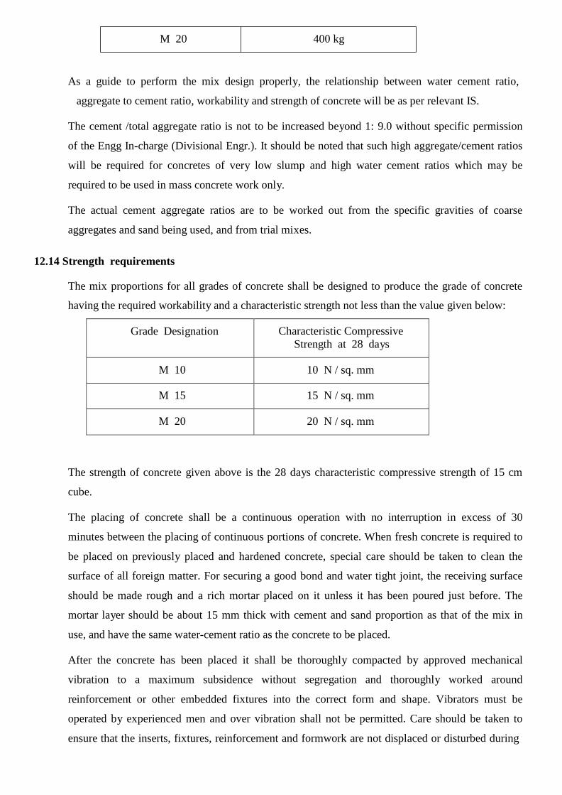
M 20 400 kg
As a guide to perform the mix design properly, the relationship between water cement ratio,
aggregate to cement ratio, workability and strength of concrete will be as per relevant IS.
The cement /total aggregate ratio is not to be increased beyond 1: 9.0 without specific permission
of the Engg In-charge (Divisional Engr.). It should be noted that such high aggregate/cement ratios
will be required for concretes of very low slump and high water cement ratios which may be
required to be used in mass concrete work only.
The actual cement aggregate ratios are to be worked out from the specific gravities of coarse
aggregates and sand being used, and from trial mixes.
12.14 Strength requirements
The mix proportions for all grades of concrete shall be designed to produce the grade of concrete
having the required workability and a characteristic strength not less than the value given below:
Grade Designation
Characteristic Compressive
Strength at 28 days
M 10
10 N / sq. mm
M 15
15 N / sq. mm
M 20
20 N / sq. mm
The strength of concrete given above is the 28 days characteristic compressive strength of 15 cm
cube.
The placing of concrete shall be a continuous operation with no interruption in excess of 30
minutes between the placing of continuous portions of concrete. When fresh concrete is required to
be placed on previously placed and hardened concrete, special care should be taken to clean the
surface of all foreign matter. For securing a good bond and water tight joint, the receiving surface
should be made rough and a rich mortar placed on it unless it has been poured just before. The
mortar layer should be about 15 mm thick with cement and sand proportion as that of the mix in
use, and have the same water-cement ratio as the concrete to be placed.
After the concrete has been placed it shall be thoroughly compacted by approved mechanical
vibration to a maximum subsidence without segregation and thoroughly worked around
reinforcement or other embedded fixtures into the correct form and shape. Vibrators must be
operated by experienced men and over vibration shall not be permitted. Care should be taken to
ensure that the inserts, fixtures, reinforcement and formwork are not displaced or disturbed during

placing of concrete. No concrete shall be placed in open while it rains. If there is any sign of
washing of cement and sand, the concrete shall be entirely removed immediately. Slabs, beams and
similar structure shall be poured in one operation normally. In special circumstances with the
approval of Engg In-charge (Divisional Engr.) these can be poured in horizontal layers not
exceeding 50 cm. in depth. When poured in layers, it must be ensured that the under layer is not
hardened. Bleeding of under layer if any shall be effectively removed.
12.15 Compaction of Concrete
Compaction is necessary for production of good concrete. After the concrete has been placed it
shall be thoroughly compacted by approved mechanical vibrator to a maximum subsidence without
segregation and thoroughly worked around reinforcement or other embedded fixtures into the
correct form and shape. Vibrators must be operated by experienced men. Care should be taken to
ensure that the inserts, fixtures, reinforcement and formwork are not displaced or disturbed during
the vibration of the concrete. The Contractors shall provide standby vibrators. Vibration is
commonly used method of compaction of concrete, the use of mechanical vibrators complying
with IS 2505, IS 2506, IS 2514 and IS 4656 for compacting concrete is recommended
For all practical purposes, the vibration can be considered to be sufficient when the air bubbles
cease to appear and sufficient mortar appears to close the surface and facilitate easy finishing
operations. The period of vibration required for a mix depends upon the workability of the mix.
12.16 Curing of Concrete
In order to achieve proper and complete strength of the concrete, the loss of water from
evaporation should be prevented. Eighty to eighty five per cent of the strength is attained in the
first 28 days and hence this 28-day strength is considered to be the criterion for the design and is
called characteristic strength. The concrete after setting for 24 hours shall be cured by keeping the
concrete wet continuously for a period of 10 days after laying.
The curing increases compressive strength, improves durability, impermeability and abrasion
resistance. Failure to carry out satisfactory curing can lead to cracking in the concrete. This in turn
can lead to salt attack of the reinforcement and consequential failure of the structure. If cracks
occur in a structure which are severe enough to affect the structure, the Contractor shall cut out and
replace the defective concrete at his own cost. The Contractor‘s attention is, therefore, drawn to
this particular aspect of proper and adequate curing
12.17 Removal of formwork
Formwork shall be kept in position fully supported, until the concrete has hardened and gained
sufficient strength to carry itself and any loads likely to be imposed upon it. Stripping must be
effected in such a manner and at such a time that no shock or other injury is caused to the concrete.

The responsibility for safe removal rests with the Contractor but the Engg In-charge (Divisional
Engr.) may delay the time of striking if he deems it necessary.
Minimum periods, in the absence of agreement to the contrary, between completion of concreting and
removal of forms are given below but due regard must be paid to the method of curing and prevailing
conditions during this period.
Removal of forms are to be done as under
i) Sides of foundations, columns, beams and wall 2days
ii) Under side of slabs up to 4.5 m span 7days
iii) Under side of slabs above to 4.5 m span
and underside of beams and arches up to 6m span 14days
iv) Under side of beams and arches above 6m and up to 9m span 21days
12.18 WATER SUPPLY
The Contractor shall be overall responsible for supply of water within switchyard / control room
for fire fighting, drinking purposes and other miscellaneous purposes. Water shall be made
available at a single point by the Employer. The scope is also inclusive of supply and erection of
all over head tanks, pipes, fittings etc. required for the water supply to be taken from the terminal
point to the respective required areas. A scheme shall be prepared by the contractor indicating the
layout and details of water supply which shall subject to the approval of the Engg In-charge
(Divisional Engr.) before actual start of work. Any extra bore holes required shall be within the
scope of the contractor.
There shall be pump houses for the bore wells and approach road to the pump houses shall be
provided.
The Contractor shall have overall responsibility to provide a suitable arrangement for permanent
supply for and retention of water within switchyard building and to the yard for watering to the
earth pits, drinking purposes. The submersible pump shall be 1.5HP and all control as per standard
has to be provided.
12.19 EARTHING :
Earth Grid should not be more than TWO meters square. This should be done by using 75x10 mm
GI flats. Earth risers should be 50x6 mm GI flats. All equipments & metal parts of the Sub-
Station should be connected with main earth grid by using 50x6 GI flats at two different places.
The main earth grid should be laid not less than 600 mm below the finished ground level. The lap

welding should not less than 100 mm. The welding of joints should be done after removal of Zinc
by using Blow lamps. Welding should be done in all four sides and should be double layer
continuous. Before taking up the second layer welding the deposited flux should be removed.
During welding the two flats should be tightened properly by using ‗ C ‗ clamps. Immediately after
welding two layers of anti-corrosive paints should be painted over the welded portion along with
two coats of Black bituminous paints. Before back filling of earth trenches the welded portion
should be covered by wrapping with bituminous tape properly and also jointing portion should be
covered with PCC (1:2:4) mix. The backfilling of earth pits and trenches should be done with
powered loam soil mixed with Bentonate powder (10:1) mix.
All equipments, steel structures etc should be connected with Main earth mat at two rows
separately. All LAs, PTs , Columns having spikes should individually connected with individual
Pipe electrodes and again should be connected with main earth grid at two separate places. The
Neutral of Power Transformer should be connected with two separate pipe electrodes and again
connected with main earth electrodes at two separate places. The separation distance between each
pipe electrodes should not be less than 2 mts. The back filling of pipe electrodes should be done in
layer of Charcoal, Salt & loam soil mixed with Bentonate power.
There should be a closely spaced earth grid ( 1.5 mts square having .5 mts spacing) below the
mechanism boxes of each Isolators & AB switches. In Sub-station the diameter of pipe electrode
should not be less than 50 mm. The Flange( 50x6) mm GI flat should be welded in all sides with
Pipe electrode. In each face of Flange there should be two nos 17.5 mm hole to accommodate 16
mm GI Bolt nut with 1 no spring washer.
Each handles of Isolators/AB switches etc should be connected with earth grid by using flexible
Tinned Copper earth bonds. In each earth switches TWO nos flexible earth bonds should be
provided. Each earth pits having pipe electrodes should be provided 250 mm Brick wall chambers
with RCC cover Slab.

12.20 Laying and installing of cables
12.20.1 General
For cable laying the following shall apply:
a) Switchyard area In concrete cable troughs (cable trench having cable racks
with cable trays)
b) Control Room On cable racks consisting of slotted type and ladder type cable trays
c) Buildings Conduits
Directly buried cables shall be used wherever necessary with the approval of Engg. Incharge
(Divisional Engr.).
12.20.2 Laying of cable
Cables shall be laid in concrete troughs provided under this contract or drawn into pipes or ducts or
on cable racks or directly buried as may be required by the Engg. Incharge (Divisional Engr.).
Concrete troughs shall be designed so that the cables are supported on cable support systems and
the supports shall be arranged so as to allow the segregation of power, control (including CT and
VT circuits) and communications cables onto different layers of cable supports. All cable supports
shall be earthed in accordance with IS 3043. The minimum vertical separation between layers of
cable tray shall be not less than 300 mm.

The cable support system shall be designed and constructed to carry the required cables without
undue crowding of the supports and without overloading the supports. The maximum number of
layers of cable that shall be permitted on a single cable support shall be three. The width of the
cable supports shall be selected to ensure that the supports are not crowded, the cable supports are
not overloaded and that sufficient space is provided in the cable trough to allow for personnel
access during and after cable installation. The width of cable supports should not exceed 750 mm.
Cables shall be laid direct in the ground only at the discretion of the Engg. Incharge (Divisional
Engr.). All cables laid direct in the ground outside buildings shall be laid in a trench and protected
by reinforced concrete slabs or cable tiles.
For auxiliary cables the top of the slab or tile shall be at a depth not less than 300 mm below the
surface of the ground and there shall be a layer of fine well packed riddled earth 75 mm thick in
between the cable and the bottom of the trench and between the top of the cable and the underside
of the slab.
The Contractor shall be responsible for the proper laying of all cables in the ground. Where cables
in the same trench are laid over each other, they shall be separated by not less than 75 mm of
riddled earth. The riddled earth used for this purpose shall have been passed through a screen
having a 12 mm square mesh.
Where cables pass under roadways they shall be laid in pipes at a depth not less than 800 mm
below the surface.
The Contractor shall be responsible for the excavation of trenches which shall include all pumping
and baling required and the provision of all necessary labour, plant, tools, water, additional soil,
fuel or motor power for such purposes.
Cables in trenches will be inspected by the Engg. Incharge (Divisional Engr.) before the trenches
are backfilled.
The running of communications and power cables along the same route shall be avoided as far as
possible. Where this is not possible they shall be segregated, the one group from the other. Power
and communication cables shall be laid in separate tiers. For other than directly buried cables the
order of laying of various cables shall be as follows:
a) Power cables on top tiers.
b) Control/ instrumentation and other service cables in bottom tiers.
12.20.3 Cable tags and markers

Each cable and conduit run shall be tagged with numbers that appear in the cable and conduit
schedule.
The tag shall be of aluminum with the number punched on it and securely attached to the cable
conduit by not less than two turns of 20 SWG GI wire conforming to IS 280. Cable tags shall be of
rectangular shape for power cables and of circular shape for control cables.
Location of cables laid directly in the ground shall be clearly indicated with cable marker made of
galvanised iron plate.
Location of buried cable joints shall be indicated with a cable marker having an additional
inscription "Cable joint".
Cable markers shall project 150 mm above ground and shall be spaced at an interval of 30 meters
and at every change in direction. They shall be located on both sides of road and drain crossings.
Cable tags shall be provided on all cables at each end (just before entering the equipment
enclosure), on both sides of a wall or floor crossing, on each duct, conduit entry and at every
twenty meters (20 m) in cable tray/trench runs. Cable tags shall be provided inside switchgear,
motor control centres, control and relay panels etc. and wherever required for cable identification
when a number of cables enter together through a gland plate.
The price of cable tags and markers shall be included in the installation rates for cables/conduits
quoted by the Bidder.
12.20.4 Cable supports and cable tray mounting arrangements in control room
The control room will normally be provided with embedded steel inserts on concrete floors/walls
for the purpose of cabling in the control room. The supports shall be secured by welding to these
inserts or available building steel structures. However, in cases where no such embedded steel
inserts are available, the same shall have to secure to the supports on walls or floors by suitable
anchoring.
12.20.5 Cable support structure in switchyard cable trenches
The contractor shall fabricate and install cable support structures in cable trenches. These supports
shall be provided at 750 mm spacing along the run of cable trenches.
Cable supports and cable racks shall be fabricated from standard structural steel members,
channels, angles and flats of required size. The fabrication. welding and erection of these structures
shall conform to the relevant clauses of this Specification, in addition to the specification given
herein.

12.20.6 Termination of cables and wires
Where cables leave the apparatus in an upward direction the cable boxes shall be provided with a
barrier joint to prevent leakage of cable oil or compound into the apparatus. Where cable cores are
liable to contact with oil or oil vapour the insulation shall be unaffected by oil.
PVC sheathed cables shall be terminated by compression glands complying with BS 6121 (or
equivalent).
Auxiliary PVC insulated cables shall be terminated with compression type glands, clamps
or armour clamps complete with all the necessary fittings.
Colours shall be marked on the cable box, cable tail ends and single core cables at all connecting
points and/or any positions the Engg. Incharge (Divisional Engr.) may determine. Cable
boxes shall be provided with suitable labels indicating the purpose of the supply where such
supply is not obvious or where the Engg. Incharge (Divisional Engr.) may determine.
All cables shall be identified and shall have phase colours marked at their
termination.
All incoming and outgoing connections shall be terminated at a terminal block. Direct termination
into auxiliary switches will not be accepted.
BREAKER FOUNDATION DESIGN

BREAKER ROD DETAILS
ROD BINDING SCHEDULE REQUIREMENT OF RODS
SIZE
VCB
Total Mtr
Kg./Mtr
TOTAL in Kg.
A. 10 tor 2*8*1.8 = 28.8 0.630 18.144
B. 10 tor 2*13*1.1 = 28.6 0.630 18.018
C. 12 tor 2*10*1.8 = 36 0.888 31.968
D. 6 tor 2*7*1.38 = 19.32 0.222 4.289
72.41904 / 120
Wet Hard Soil Soil
EXCAVATION: 2.15*1.4*1.2 = 3.612 Cum. 12.481 PCC:1:4:8 2.15*1.4*0.075 = 0.226 Cum. 0.462
RCC:1:2:4 1.2*1.915*0.2 = 0.4596 Cum.
2*(1.0*0.5*1.4) = 1.4 Cum.
1.8596 Cum. 2.421

Foundation for 11 KV KIOSK
EXCAVATION: 2.5 x 1.2 x 1.0 = 3 cum.
PCC:1:4:8 2.5 x 1.2 x 0.075 = 0.225 cum. ( 5.0 +1.5) x 1.3 x
Brick 0.25 = 2.11 cum.
Sand 2 x 0.7 x 1.3 = 1.82 cum.
RCC i) 2.5 x 1.2 x 0.15 = 0.45 cum.
ii) (0.2 x 0.2 x 1.3) x 4 = 0.21 cum.
Rod 10 tor = 60 Kg.

Single Isolator Foundation Design
CIVIL WORKS LIST OF FOUNDATION BOILTS
Ex-2.1 x 0.9 x1.250 x 2 = 4.725 2.5 mm x 700 mm foundation bolts-8 Nos.
PCC (1 : 4 : 8)-2.1 x 0.9 x 0.075 x 2 = 0.283 2.730 Kg x 8 =21.840 Kg
RCC- (a) 1.9 x 0.7 x 0.250 x 2 = 0.665 Plate 75 x 12….8 Nos. = 4.240 Kg.
(b) 1.25 x 0.7 x 1.25 x 2 =2.188 26.080 Kg.
Total =2.853 Nut Bolt washers 13.632 Kg.
Total Wt. of members 268.813 Kg
Total =308.525 Kg.

CONTROL CABLE TRENCH

11 Kv Cable Trench
Abstract for Cable Trench
For 10 Mtrs. For 10 mtr For 1 Mtr
1 Excavation 0.870*2.0*10 17.4 cum. 1.74 cum.
2 PCC 0.075*2.0*10 1.5 cum. 0.15 cum.
3 RCC (1:2:4)
(a) Base 1.8*0.1*10 1.8 cum.
(b) Pillar 4*(0.25*1.02*0.25) 0.255 cum.
(c) Over Brick work (top) 0.25*0.075*10 0.1875 cum. (d) Over Brick work (top)
on Pillar side
0.25*0.075*9
0.1688 cum.
0.241
cum.
4 Brick Masonary(1:5)
(a) No pillar side 0.25*0.94*10 2.35 cum.
(b) Pillar side 0.25*0.94*9 2.115 cum. 0.447 cum.
5 Plastering (1:6)
Inside 2*10*1.02 20.4 cum.
Outside 2*10*0.5 10 cum. 3.04 cum.
6 G.I. Flat 50 x 6 0.2*2*4 1.6 *2.4kg 0.384 Kg.
Abstract of ROD Wt. 10% Extra

12 tor 19.68 mtr
8 tor 245 mtr
6 tor 29.2 mtr
17.57 kg 19 Kg. 95.55 kg. 105 Kg. 6.424 kg. 7 Kg.
131 Kg. 13.1 Kg.
ROAD INSIDE SUB STATION
Per Mtr
1 Excavation : 0.550mx1.0mx3.5m = 1.925 cum
2 Boulder Packing : 0.5mx 1.0mx3.5m = 1.750 cum
3 W.Base course : i) 0.075 m x 1.0m x 3.5m = 0.2625 0.525 cum
: ii) 0.075 m x 1.0m x 3.5m = 0.2625
4 PCC(1:2:4) : 0.1m x 1.0m x 3.5m = 0.35 cum
5 Brick work : i) 0.25 m x 0.25m x 1.0m = 0.0625 ii) 0.30 m x 0.25/2 m x
1.0m = 0.0375
0.1 cum

TRANSFORMER FOUNDATION
FOUNDATION DETAIL FOR POWER TRANSFORMER
1 EXCAVATION: 3m x 3 x 1.1 m = 9.9 Cum.
in Hard Soil
2 Stone Grating by using RRHG Boulder of 250 mm size maximum
3m x 3 m x 0.5m = 4.5 Cum.
3 PCC:1:4:8
3m x 3 m x 0.075m =
0.675 Cum.
4 RCC:1:2:4 i) 3m x 3 m x 0.2m = 1.8 Cum.
(Above RRGH)

ii) 2*(2.7 x0.6 x 0.925 m) = 2.997 Cum.
Lengh x width x height)
iii) Side Wall 0.075 m x [2.8 m +2.8 m +2.8 m+ {3-(0.1+0.1+0.6+0.6)}m]x 0.625
Thickness side1 x side2xside3
0.075 x 0.625 x 10.0 = 0.4688 Cum.
Total RCC (i+ii+iii) 5.26 Cum.
ROD a) 12 tor 2.9m x 20 x4 = 232 @ 0.888 kg. = 206.016 Kg.
150 C/C b) 10 tor 0.9 x 70 = 63 @ 0.617 = 38.871 Kg.
100 C/C c) 10 tor 1.28 x 5 = 6.4 @ 0.617 = 3.9488 Kg.
d) 8 tor 10 x 6 = 60 @ 0.395 = 23.7 Kg.
Beam a) 16 tor 2 x (26x2+10)x1.775 = 220.1 @ 1.58 = 347.758 Kg.
b) 8 tor 2x(8x6.4)m = 102.4 @ 0.395 = 40.448 Kg.
660.742 Kg.
STEEL:
500 x 500 x 10 mm G.I. Base Plate- 6 No.
65 x 65 x 6 mm MS Angle - 2 No. x 2.7 m =5.4 mtr.
70 lb Rail Pole- 2 No. x 2.7 = 5.4 mtr.

Foundati on for T1………. T5 Col umns
1 Excavation : 2.15m x 2.15 m x 1.825 m = 8.436 cum
2 PCC (1:4:8) : 2.15m x 2.15 m x 0.075 m = 0.3467 cum
3 RCC (1:2:4) : (2 m x 2 m x 0.25 m) +
(0.8 m x 0.8 m x 2.15 m) 2.376 cum
=
4 Base Plate 620 x 620 12 mm GI- 36 Kg. welded to column.
5 Foundation Bolts- GI) 32 mm x 1400 mm = 8.834 kg
6 ROD 12 Tor : 2.4 m x 12 No.=28.8 m x 0.888 kg. = 25.57 Kg. 91.76
10 Tor : 2.0 m x 44 No= 88 m x 0.63 = 55.44 Kg. = 90 kg.
6 mm : 2.42 m x 20 no. = 48.4m x 0.222 kg. = 10.74 Kg.


