TSFLUXUS_G7V1-4-1EN_Leu, 2011-03-16 1 Technical Specification FLUXUS ® G70x Permanently Installed Gas Ultrasonic Flowmeter Designed for wall mounting or installation in 19'' rack systems Features • Non-invasive measurement using the clamp-on tech- nology for precise bi-directional, highly dynamic flow measurement • approved transducers for hazardous areas available • Automatic loading of calibration data and transducer detection reduce set-up times and provide precise, long-term stable results • Transducers available for a wide range of inner pipe diameters ( ) and fluid temperatures ( ) • Proven clamp-on technology, transducers resistant to dust and humidity • Measurement is unaffected by gas density, viscosity and composition, dust, humidity, temperature or pres- sure • User-friendly design Applications • Designed for industrial use in harsh environments, in gas processing and natural gas extraction, chemical in- dustry and in the petroleum industry. Practical applica- tions: - Measurement on natural gas pipelines and in natural gas storage installations - Measurement of synthesized gas and injection gas - Measurement for the gas supply industry ATEX, IEC, FM 7...1600 mm -40...+200 °C FLUXUS FLUXUS Measurement with transducers mounted by Variofix L G704 G709
Transcript
TSFLUXUS_G7V1-4-1EN_Leu, 2011-03-16 1
Technical Specification
FLUXUS® G70x
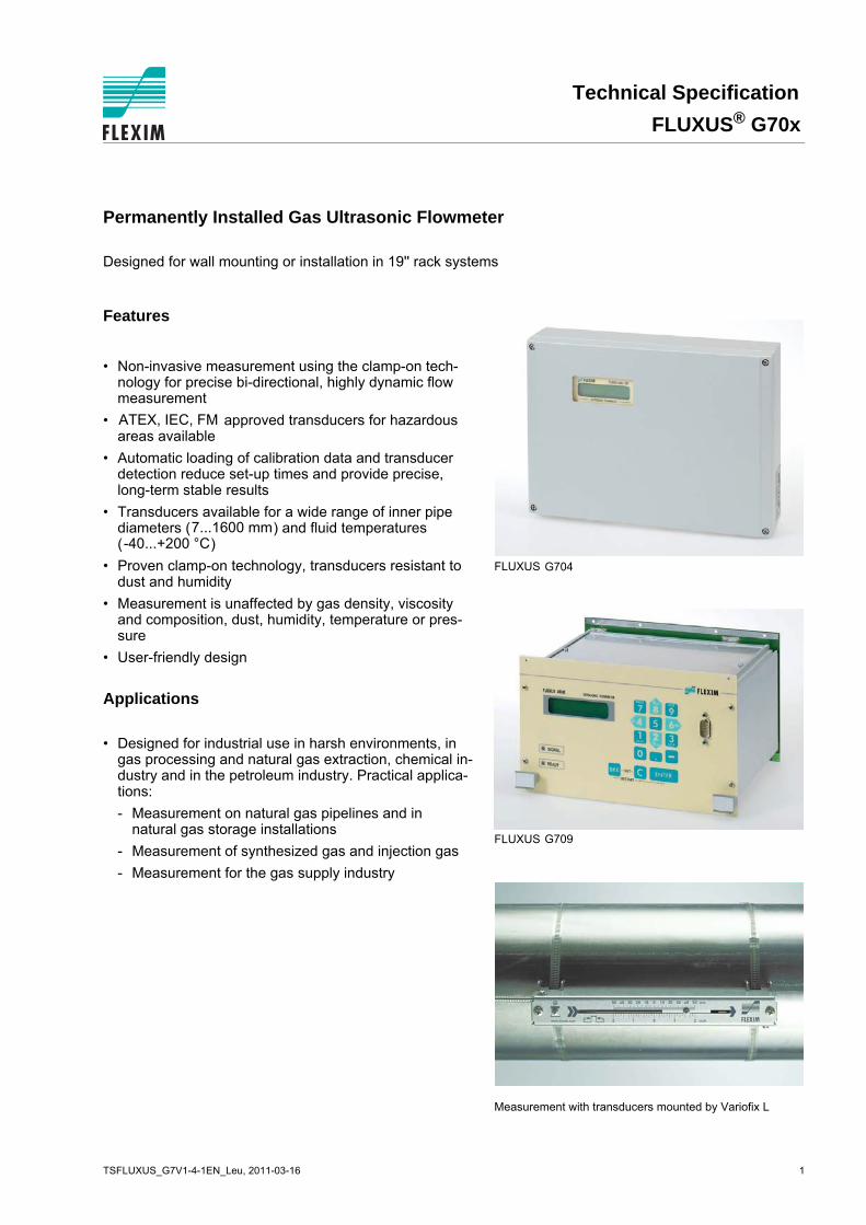
Permanently Installed Gas Ultrasonic Flowmeter
Designed for wall mounting or installation in 19'' rack systems
Features
• Non-invasive measurement using the clamp-on tech-nology for precise bi-directional, highly dynamic flow measurement
• approved transducers for hazardous areas available
• Automatic loading of calibration data and transducer detection reduce set-up times and provide precise, long-term stable results
• Transducers available for a wide range of inner pipediameters ( ) and fluid temperatures ( )
• Proven clamp-on technology, transducers resistant to dust and humidity
• Measurement is unaffected by gas density, viscosity and composition, dust, humidity, temperature or pres-sure
• User-friendly design
Applications
• Designed for industrial use in harsh environments, in gas processing and natural gas extraction, chemical in-dustry and in the petroleum industry. Practical applica-tions:
- Measurement on natural gas pipelines and in natural gas storage installations
- Measurement of synthesized gas and injection gas
- Measurement for the gas supply industry
ATEX, IEC, FM
7...1600 mm-40...+200 °C
FLUXUS
FLUXUS
Measurement with transducers mounted by Variofix L
G704
G709
FLUXUS® G70x Technical Specification
Table of Contents
2 2011-03-16, TSFLUXUS_G7V1-4-1EN_Leu
Function .......................................................................................................................................................... 3
Calculation of Volumetric Flow Rate ................................................................................................................ 3
Number of Sound Paths.................................................................................................................................... 4
Technical Data ................................................................................................................................................. 6
Transducer Order Codes ............................................................................................................................... 15
Technical Data ............................................................................................................................................... 16
Connection Systems .................................................................................................................................... 47
Technical Data ............................................................................................................................................... 49
Temperature Probes (optional) ................................................................................................................... 52
TSFLUXUS_G7V1-4-1EN_Leu, 2011-03-16 3
Technical Specification FLUXUS® G70x
Function
Calculation of Volumetric Flow Rate
Q = kRe . A . ka . t/(2 . tfl)
where:
Measurement Principle
In order to measure the flow of a medium in a pipe, ultrasonic signals are used, employing the transit time dif-ference principle. Ultrasonic signals are emitted by a transducer installed on one side of a pipe, reflected bythe opposite pipe wall and received by a second transducer. These signals are emitted alternately in the flowdirection and against it.
As the medium in which the signals propagate is flowing, the transit time of the ultrasonic signals in the flowdirection is shorter than against the flow direction.
The transit time difference, t, is measured and allows the flowmeter to determine the average flow velocityalong the propagation path of the ultrasonic signals. A flow profile correction is then performed in order to ob-tain the area averaged flow velocity, which is proportional to the volumetric flow rate.
The received ultrasonic signals will be checked for their usefulness for the measurement and the plausibilityof the measured values will be evaluated. The complete measuring cycle is controlled by the integrated mi-croprocessors. Disturbance signals will be eliminated.
Path of the ultrasonic signal Transit time difference t
Q - volumetric flow rate kRe - fluid mechanics calibration factor A - cross-sectional area of the pipe ka - acoustical calibration factor t - transit time difference tfl - transit time in the medium
��
��
��
4 2011-03-16, TSFLUXUS_G7V1-4-1EN_Leu
FLUXUS® G70x Technical Specification
.
Number of Sound Paths
The number of sound paths is the number of transits of the ultrasonic signal through the medium in the pipe.Depending on the number of sound paths, the following methods of installation exist:
• reflection modeThe number of sound paths is even. Both of the transducers are mounted on the same side of the pipe. Correct positioning of the transducers is easier.
• diagonal modeThe number of sound paths is odd. Both of the transducers are mounted on opposite sides of the pipe. In the case of a high signal attenuation by the medium, pipe and coatings, diagonal mode with 1 sound path will be used.
The preferred method of installation depends on the application. While increasing the number of sound pathsincreases the accuracy of the measurement, signal attenuation increases as well. The optimum number ofsound paths for the parameters of the application will be detemined automatically by the transmitter.
As the transducers can be mounted with the transducer mounting fixture in reflection mode or diagonal mode,the number of sound paths can be adjusted optimally for the application.
a - transducer distance
Reflection mode, number of sound paths: 2
Diagonal mode, number of sound paths: 3
Diagonal mode , number of sound paths: 1 Diagonal mode , number of sound paths: 1,negative transducer distance
a
a
a > 0 a < 0
TSFLUXUS_G7V1-4-1EN_Leu, 2011-03-16 5
Technical Specification FLUXUS® G70x
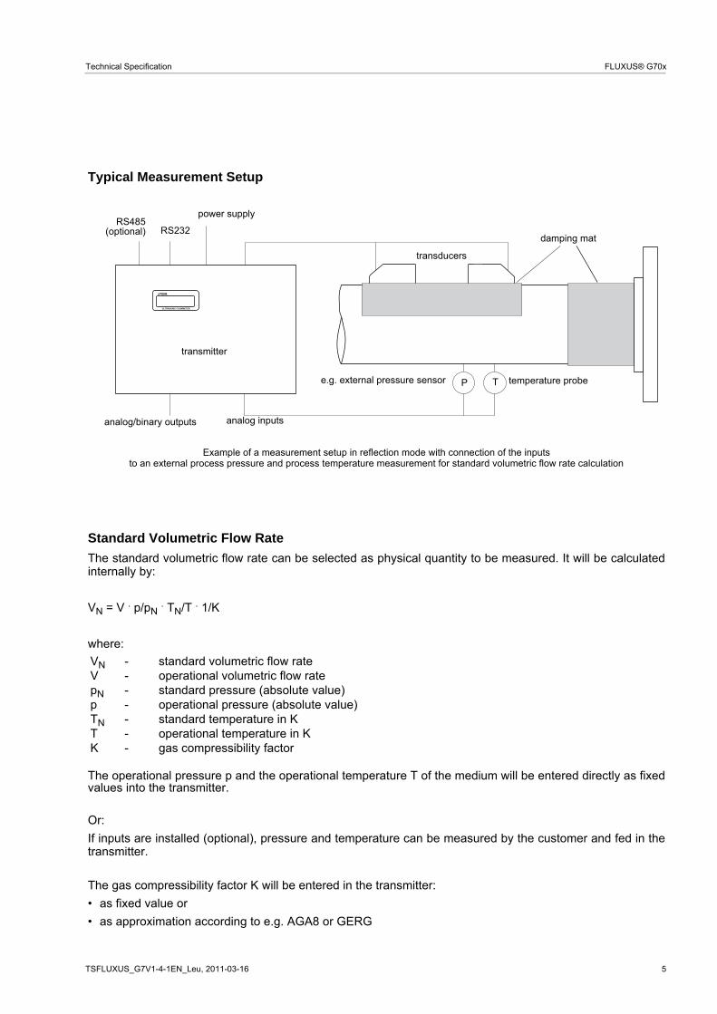
Typical Measurement Setup
Example of a measurement setup in reflection mode with connection of the inputsto an external process pressure and process temperature measurement for standard volumetric flow rate calculation
Standard Volumetric Flow Rate
The standard volumetric flow rate can be selected as physical quantity to be measured. It will be calculatedinternally by:
VN = V . p/pN . TN/T . 1/K
where:
The operational pressure p and the operational temperature T of the medium will be entered directly as fixedvalues into the transmitter.
Or:
If inputs are installed (optional), pressure and temperature can be measured by the customer and fed in thetransmitter.
The gas compressibility factor K will be entered in the transmitter:
• as fixed value or
• as approximation according to e.g. AGA8 or GERG
� � � � � � � � � � � � � � � �
P T
transducers
damping mat
transmitter
RS232
analog/binary outputs analog inputs
power supply
temperature probe e.g. external pressure sensor
RS485(optional)
VN - standard volumetric flow rate V - operational volumetric flow rate pN - standard pressure (absolute value) p - operational pressure (absolute value) TN - standard temperature in K T - operational temperature in K K - gas compressibility factor
6 2011-03-16, TSFLUXUS_G7V1-4-1EN_Leu
FLUXUS® G70x Technical Specification
Flow Transmitter
Technical Data
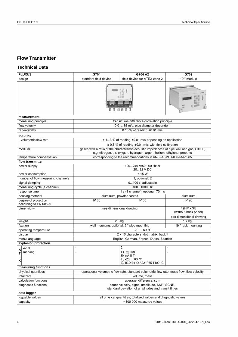
FLUXUS G704 G704 A2 G709design standard field device field device for ATEX zone 2 19 " module
measurement measuring principle transit time difference correlation principle flow velocity
repeatability 0.15 % of reading
accuracy- volumetric flow rate ± 1...3 % of reading depending on application
± 0.5 % of reading with field calibrationmedium gases with a ratio of the characteristic acoustic impedances of pipe wall and gas < 3000,
e.g. nitrogen, air, oxygen, hydrogen, argon, helium, ethylene, propanetemperature compensation corresponding to the recommendations in ANSI/ASME MFC-5M-1985flow transmitter power supply 100...240 V/50...60 Hz or
20...32 V DCpower consumption < 15 Wnumber of flow measuring channels 1, optional: 2signal damping 0...100 s, adjustablemeasuring cycle (1 channel) 100...1000 Hzresponse time 1 s (1 channel), optional: 70 mshousing material aluminum, powder coated aluminum degree of protectionaccording to EN 60529
IP 65 IP 65 IP 20
dimensions see dimensional drawing 42HP x 3U(without back panel)
see dimensional drawing weight fixation wall mounting, optional: 2 " pipe mounting 19 " rack mounting operating temperature -20...+60 °C display 2 x 16 characters, dot matrix, backlitmenu language English, German, French, Dutch, Spanishexplosion protection
ATEX
zone - 2 -marking - II3G
Ex nA II T4Ta -20...+60 °C
II3D Ex tD A22 IP65 T100 °C
-
measuring functions physical quantities operational volumetric flow rate, standard volumetric flow rate, mass flow, flow velocitytotalizers volume, mass calculation functions average, difference, sum diagnostic functions sound velocity, signal amplitude, SNR, SCNR,
standard deviation of amplitudes and transit timesdata logger loggable values all physical quantities, totalized values and diagnostic values capacity > 100 000 measured values
0.01...35 m/s, pipe diameter dependent
±0.01 m/s
±0.01 m/s
±0.01 m/s
2.8 kg 1.7 kg
TSFLUXUS_G7V1-4-1EN_Leu, 2011-03-16 7
Technical Specification FLUXUS® G70x
communication interface - process integration: optional: RS485 (Modbus, sender) or HART
- diagnosis: RS232 serial data kit (optional)
software (all WindowsTM versions) - FluxData: download of measured data, graphical presentation,conversion to other formats (e.g. for ExcelTM)
- FluxKoef: creating medium data setscable RS232
adapter RS232 - USBoutputs (optional)
The outputs are galvanically isolated from the transmitter. number on request
current output current output - range 0/4...20 mA - accuracy 0.1 % of reading ±15 A- active output Rext < 500 - passive output Uext = 4...24 V, dependent on Rext, Rext < 1 kcurrent output I1 in HART mode - range 4...20 mA- passive output Uext = 10...24 V
voltage output range 0...1 V or 0...10 Vaccuracy 0...1 V: 0.1 % of reading ±1 mV
0...10 V: 0.1 % of reading ±10 mVinternal resistance Ri = 500
frequency output range 0...1 kHz or 0...5 kHzopen collector 24 V/4 mA
binary output Reed relay - 48 V/0.25 Aopen collector - 24 V/4 mAoptorelay 26 V/100 mA -binary output as alarm output - functions limit, change of flow direction or error limit, change of flow direction
or error binary output as pulse output - pulse value 0.01...1000 units 0.01...1000 units- pulse width 1...1000 ms 80...1000 msinputs (optional)
The inputs are galvanically isolated from the transmitter. number max. 4, on request
temperature input designation Pt100/Pt1000connection 4-wire range -150...+560 °C resolution 0.01 Kaccuracy ±0.01 % of reading ±0.03 K
current input range active: 0...20 mA
passive: -20...+20 mAaccuracy 0.1 % of reading ±10 Aactive input Ui = 24 V, Ri = 50 , Pi < 0.5 W, not short circuit proofpassive input Ri = 50 , Pi < 0.3 W
voltage input range 0...1 Vaccuracy 0.1 % of reading ±1 mVinternal resistance Ri = 1 M
FLUXUS G704 G704 A2 G709
8 2011-03-16, TSFLUXUS_G7V1-4-1EN_Leu
FLUXUS® G70x Technical Specification
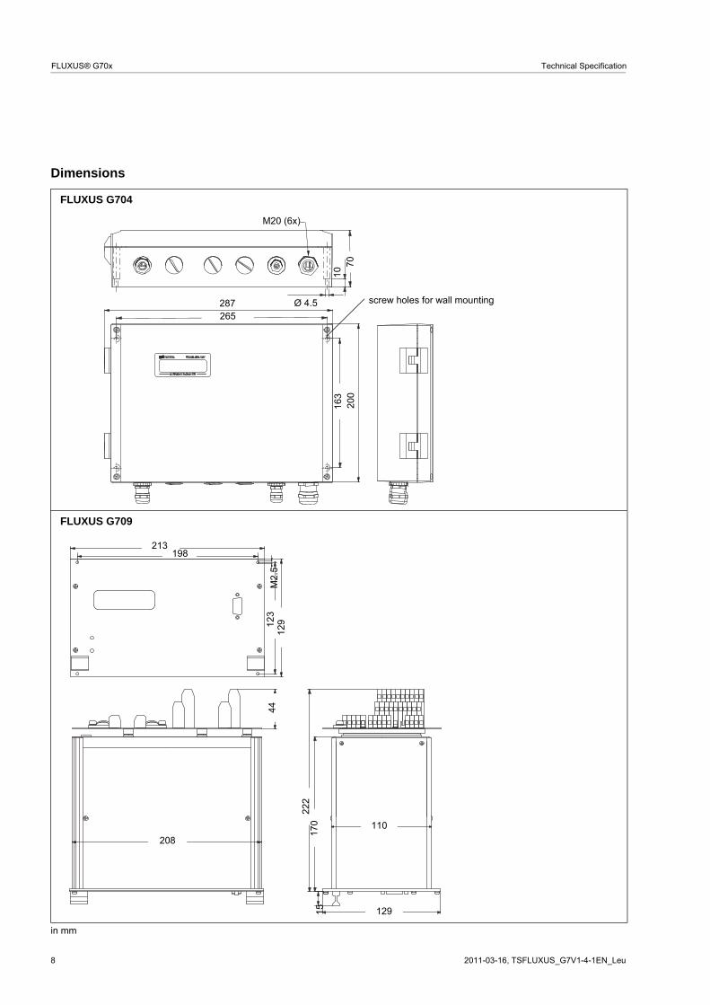
Dimensions
FLUXUS G704
FLUXUS G709
in mm
70
10
Ø 4.5
163 20
0
287
M20 (6x)
265
screw holes for wall mounting
208
129
222
15
123
110
M2.
544
213
129
170
198
TSFLUXUS_G7V1-4-1EN_Leu, 2011-03-16 9
Technical Specification FLUXUS® G70x
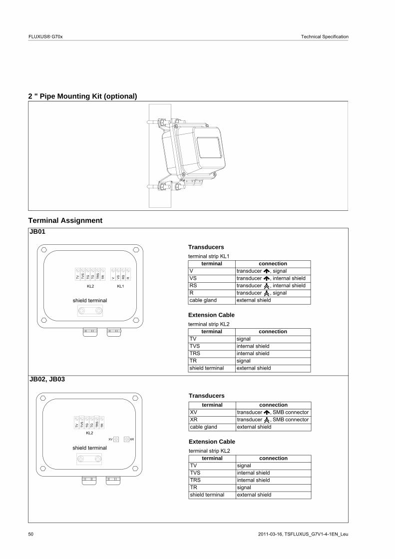
2 " Pipe Mounting Kit (optional)
FLUXUS G704
for vertical and horizontal pipes
10 2011-03-16, TSFLUXUS_G7V1-4-1EN_Leu
FLUXUS® G70x Technical Specification
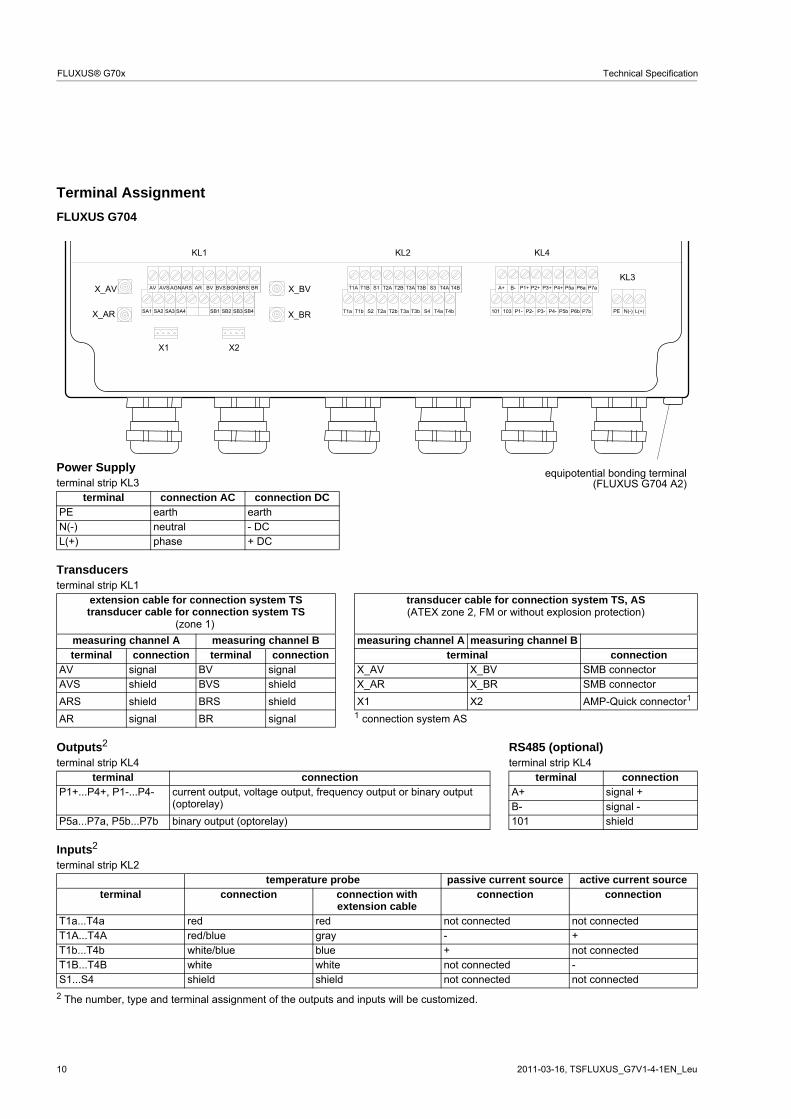
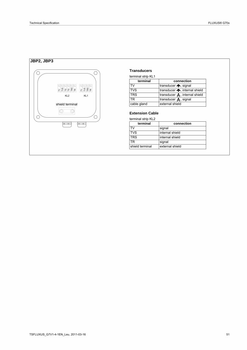
Terminal Assignment
2 The number, type and terminal assignment of the outputs and inputs will be customized.
FLUXUS G704
Power Supply terminal strip KL3
terminal connection AC connection DCPE earth earth N(-) neutral - DCL(+) phase + DC
Transducers terminal strip KL1
extension cable for connection system TStransducer cable for connection system TS
transducer cable for connection system TS, AS
measuring channel A measuring channel B measuring channel A measuring channel Bterminal connection terminal connection terminal connection
AV signal BV signal X_AV X_BV SMB connector AVS shield BVS shield X_AR X_BR SMB connector
T1a...T4a red red not connected not connected T1A...T4A red/blue gray - +T1b...T4b white/blue blue + not connected T1B...T4B white white not connected -S1...S4 shield shield not connected not connected
T1a...T4a red red not connected not connected T1A...T4A red/blue gray - +T1b...T4b white/blue blue + not connected T1B...T4B white white not connected -S1...S4 shield shield not connected not connected
� " � " �� " �� " �
� " �� " �
� � % � %
� � � � �
�
��
� " � � "
� ( � � � � "
� � �
� � �
� � �
� � �
� � �
� � �
� � �
� � �
� % �
� %
� � �
� & �
� �
� % �
� %
� � �
� & �
� �
� � �
� � �
� �
� �
� �
" �
" �
�
" �
� �
� � $
� $
� �
� � $
� � �
� � �
� � �
� � �
� � �
� � �
� � #
� #
� �
� � #
� � �
� � �
� � �
� � �
� � �
� � �
� � �
� � �
� � �
� �
� � �
� � �
� � �
� � �
� �
� � �
� � $
� � #
� � #
� �
� � $
� � #
� � #
� � $
� �
� � $
(zone 1)(ATEX zone 2, FM or without explosion protection)
12 2011-03-16, TSFLUXUS_G7V1-4-1EN_Leu
FLUXUS® G70x Technical Specification
Transducers
Transducer Selection
Step 1a
Select a Lamb wave transducer:
Step 1b
If the pipe wall thickness is not in the range of the Lamb wave transducers, select a shear wave transducer:
Step 2
inner pipe diameter d dependent on the flow velocity v of the medium in the pipe
The transducers are selected from the characteristics (see next page). Lamb wave transducers are selectedfrom the left column, shear wave transducers from the right column.
Lamb wave transducers: If the values d and v are not in the range, diagonal mode with 1 sound path may beused, i.e. the same characteristics can be used with doubling the inner pipe diameter. If the values are still notin the range, shear waves transducers regarding the pipe wall thickness have to be selected in step 1b.
transducer order code
GLG 11 23
GLH 7 15
GLK 4 9
GLM 2 5
GLP 1...3
GLQ 0.5...1
5 10 15 20 25pipe wall thickness [mm]
transducer order code
GSG 14 23
GSK 5 9
GSM 2.5 5
GSP 1.5 3
5 10 15 20 25pipe wall thickness [mm]
recommended possible
TSFLUXUS_G7V1-4-1EN_Leu, 2011-03-16 13
Technical Specification FLUXUS® G70x
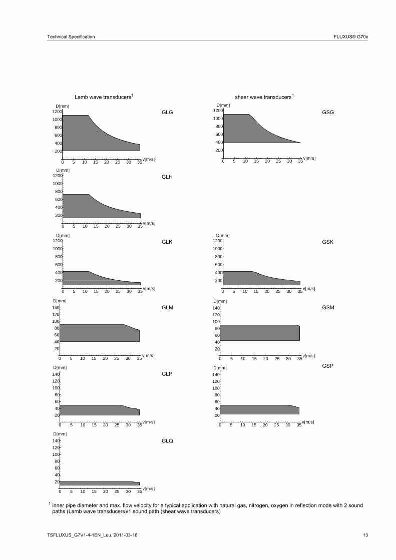
Lamb wave transducers1 shear wave transducers1
GLG GSG
GLH
GLK GSK
GLM GSM
GLP
GSP
GLQ
1 inner pipe diameter and max. flow velocity for a typical application with natural gas, nitrogen, oxygen in reflection mode with 2 soundpaths (Lamb wave transducers)/1 sound path (shear wave transducers)
0 5 10 15 20 25 30 35v�m�s�
200
400
600
800
1000
1200D�mm�
0 5 10 15 20 25 30 35v�m�s�
200
400
600
800
1000
1200D�mm�
0 5 10 15 20 25 30 35v�m�s�
200
400
600
800
1000
1200D�mm�
0 5 10 15 20 25 30 35v�m�s�
200
400
600
800
1000
1200D�mm�
0 5 10 15 20 25 30 35v�m�s�
200
400
600
800
1000
1200D�mm�
0 5 10 15 20 25 30 35v�m�s�
20
40
60
80
100
120
140
D�mm�
0 5 10 15 20 25 30 35v�m�s�
20
40
60
80
100
120
140
D�mm�
0 5 10 15 20 25 30 35v�m�s�
20
40
60
80
100
120
140
D�mm�
0 5 10 15 20 25 30 35v�m�s�
20
40
60
80
100
120
140
D�mm�GDP
0 5 10 15 20 25 30 35v�m�s�
20
40
60
80
100
120
140
D�mm�
14 2011-03-16, TSFLUXUS_G7V1-4-1EN_Leu
FLUXUS® G70x Technical Specification
Step 3
min. medium pressure
Examples
Step 4
for determination of characters 4...11 of the transducer order code (temperature, explosion protection, con-nection system, extension cable) see page 15
Step 5
for the technical data of the selected transducer see page 16 et seqq.
Lamb wave transducers shear wave transducers transducer order code
medium pressure1 [ ] transducer order code
medium pressure1 [ ]metal pipe plastic pipe metal pipe plastic pipe
min. min. extended min. min. min. extended min. GLG 15 10 1 GSG 30 20 1
GLH 15 10 1 GSK 30 20 1
GLK 1 GSM 30 20 1
GLM - 1 GSP 30 20 1
GLP - 1
GLQ - 1
1 depending on application, typical absolute value for natural gas, nitrogen, compressed air
d - inner pipe diameter
step 1 pipe wall thickness 12 12 12 30
selected transducer GLG or GLH GLG or GLH GLG or GLH GS2 inner pipe diameter 800 600 800 300
max. flow velocity 15 15 30 15
selected transducer GLG GLG or GLH values not in the range of the characteristics, but by using diagonal mode with 1 sound path, the inner pipe diameter in the char-acteristics is doubled:GLG
GSK
3 min. medium pressure 17 17 17 35
selected transducer GLG GLG or GLHinfluence of noise is reduced with increased transducer frequency, thus rec-ommended:GLH
GLG GSK
bar bar
15 (d > 120 mm)10 (d < 120 mm)
10 (d > 120 mm)5 (d < 120 mm)
10 (d > 60 mm)5 (d < 60 mm)
10 (d > 35 mm)5 (d < 35 mm)
10 (d > 15 mm)5 (d < 15 mm)
mm
mm
m/s
bar
TSFLUXUS_G7V1-4-1EN_Leu, 2011-03-16 15
Technical Specification FLUXUS® G70x
Transducer Order Codes
1, 2 3 4 5, 6 7, 8 9...11 12, 13 no. of character
tran
sduc
er
tran
sduc
er
freq
uenc
y
- tem
pera
ture
expl
osio
npr
otec
tion
conn
ectio
nsy
ste
m
- exte
nsio
n ca
ble
/ optio
ns
description
GL set of ultrasonic flow transducers for gas measurement, Lamb wave
GS set of ultrasonic flow transducers for gas measurement, shear wave
G 0.2 MHz
H 0.3 MHz (Lamb wave only)
K 0.5 MHz
M 1 MHz
P 2 MHz
Q 4 MHz (Lamb wave only)
N normal temperature range
E extended temperature range (shear wave transducers with trans-ducer frequency M, P, Q)
A1 ATEX zone 1
A2 ATEX zone 2
F2 FM Class I Div. 2
I1 IEC zone 2
NN not explosion proof
AS with Amphenol connector
TS direct connection or connection via junction box
XXX cable length in m, for max. length of extension cable see page 47
IP68 degree of protection IP 68
OS housing with stainless steel 316
example
GL K - N A1 TS - 030 Lamb wave transducer 0.5 MHz, normal temperature range, zone 1, connection system TS with junction box JB01 and 30 m exten-sion cable
- - /
(not explosion proof transducers)
connection system TS:
0 m: without junction box
> 0 m: with junction box JB01 (zone 1), JB02 (ATEX zone 2, FM), JB03 (not explosion proof), JBP2 (IP 68 transducers for ATEX zone 2), JBP3 (not explosion proof IP 68 transducers)
(with connection system TS)
(with connection system TS)
16 2011-03-16, TSFLUXUS_G7V1-4-1EN_Leu
FLUXUS® G70x Technical Specification
Technical Data
Shear Wave Transducers (zone 1)
technical type GDG1N81 GDK1N81 GDM2N81 GDP2N81order code GSG-NA1TS
GSG-NA1TS/OSGSG-NI1TSGSG-NI1TS/OS
GSK-NA1TSGSK-NA1TS/OSGSK-NI1TSGSK-NI1TS/OS
GSM-NA1TSGSM-NA1TS/OSGSM-NI1TSGSM-NI1TS/OS
GSP-NA1TSGSP-NA1TS/OSGSP-NI1TSGSP-NI1TS/OS
transducer frequency MHz 0.2 0.5 1 2
medium pressure1
min. extended metal pipe: 20 metal pipe: 20 metal pipe: 20 metal pipe: 20min. metal pipe: 30
PEEK with stainless steel cap 304 (1.4301), option OS: 316L (1.4404)
PEEK with stainless steel cap 304 (1.4301), option OS: 316L (1.4404)
PEEK with stainless steel cap 304 (1.4301), option OS: 316L (1.4404)
contact surface PEEK PEEK PEEK PEEKdegree of protection according to EN 60529
IP 65 IP 65 IP 65 IP 65
transducer cable type 1699 1699 1699 1699length 5 5 4 4dimensions length l 129.5 126.5 62.5 62.5width b 51 51 32 32height h 67 67.5 40.5 40.5dimensional drawing
operating temperature min. °C -40 -40 -40 -40max. °C +130 +130 +130 +130temperaturecompensation
x x x x
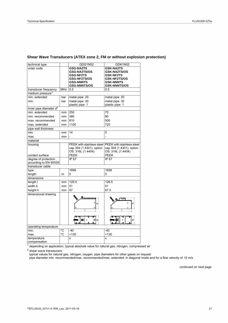
1 depending on application, typical absolute value for natural gas, nitrogen, compressed air 2 shear wave transducers:
typical values for natural gas, nitrogen, oxygen, pipe diameters for other gases on requestpipe diameter min. recommended/max. recommended/max. extended: in diagonal mode and for a flow velocity of
continued on next page
barbar
mmmmmmmm
mmmm
m
mmmmmm
l
hb
l
hb
l
hb
l
hb
15 m/s
TSFLUXUS_G7V1-4-1EN_Leu, 2011-03-16 17
Technical Specification FLUXUS® G70x
explosion protection
ATEX/IEC
Ex
transducer ATEX GSG-NA1TSGSG-NA1TS/OS
GSK-NA1TSGSK-NA1TS/OS
GSM-NA1TSGSM-NA1TS/OS
GSP-NA1TSGSP-NA1TS/OS
transducer IEC Ex GSG-NI1TSGSG-NI1TS/OS
GSK-NI1TSGSK-NI1TS/OS
GSM-NI1TSGSM-NI1TS/OS
GSP-NI1TSGSP-NI1TS/OS
zone 1 1 1 1explosion protection temperature min. °C -55 -55 -55 -55max. °C +180 +180 +180 +180marking
Ex eq II T6...T3Ex tD A21 IP65 TX
Ex eq II T6...T3Ex tD A21 IP65 TX
Ex eq II T6...T3Ex tD A21 IP65 TX
Ex eq II T6...T3Ex tD A21 IP65 TX
certification ATEX IBExU07ATEX1168 X IBExU07ATEX1168 X IBExU07ATEX1168 X IBExU07ATEX1168 Xcertification IEC Ex IECEx IBE08.0007 X IECEx IBE08.0007 X IECEx IBE08.0007 X IECEx IBE08.0007 Xtype of protection gas: increased safety,
cap 316Ti (1.4571)PEEK with stainless steel cap 316Ti (1.4571)
PEEK with stainless steel cap 316Ti (1.4571)
PEEK with stainless steel cap 316Ti (1.4571)
contact surface PEEK PEEK PEEK PEEKdegree of protection according to EN 60529
IP 68 IP 68 IP 68 IP 68
transducer cable type 2550 2550 2550 2550length 12 12 12 12dimensions length l 128.5 128.5 70 70width b 54 54 32 32height h 83.5 83.5 46 46dimensional drawing
operating temperature min. °C -40 -40 -40 -40max. °C +100 +100 +100 +100temperaturecompensation
x x x x
explosion protection
ATEX/IEC
Ex
transducer ATEX GSG-NA1TS/IP68 GSK-NA1TS/IP68 GSM-NA1TS/IP68 GSP-NA1TS/IP68transducer IEC Ex GSG-NI1TS/IP68 GSK-NI1TS/IP68 GSM-NI1TS/IP68 GSP-NI1TS/IP68zone 1 1 1 1explosion protection temperature min. °C -55 -55 -55 -55max. °C +180 +180 +180 +180marking
Ex q II T6...T3Ex tD A21 IP68 TX
Ex q II T6...T3Ex tD A21 IP68 TX
Ex q II T6...T3Ex tD A21 IP68 TX
Ex q II T6...T3Ex tD A21 IP68 TX
certification ATEX IBExU07ATEX1168 X IBExU07ATEX1168 X IBExU07ATEX1168 X IBExU07ATEX1168 Xcertification IEC Ex IECEx IBE08.0007 X IECEx IBE08.0007 X IECEx IBE08.0007 X IECEx IBE08.0007 Xtype of protection gas: powder filling
dust: protection byenclosure
gas: powder fillingdust: protection byenclosure
gas: powder fillingdust: protection byenclosure
gas: powder fillingdust: protection byenclosure
necessary trans-ducer mountingfixture
Variofix L or Variofix C Variofix L or Variofix C Variofix L or Variofix C Variofix L or Variofix C
1 depending on application, typical absolute value for natural gas, nitrogen, compressed air 2 shear wave transducers:
typical values for natural gas, nitrogen, oxygen, pipe diameters for other gases on requestpipe diameter min. recommended/max. recommended/max. extended: in diagonal mode and for a flow velocity of
barbar
mmmmmmmm
mmmm
m
mmmmmm
l
hb
l
hb
l
hb
lh
b
II2GII2D
0637 II2GII2D
0637 II2GII2D
0637 II2GII2D
0637
15 m/s
TSFLUXUS_G7V1-4-1EN_Leu, 2011-03-16 19
Technical Specification FLUXUS® G70x
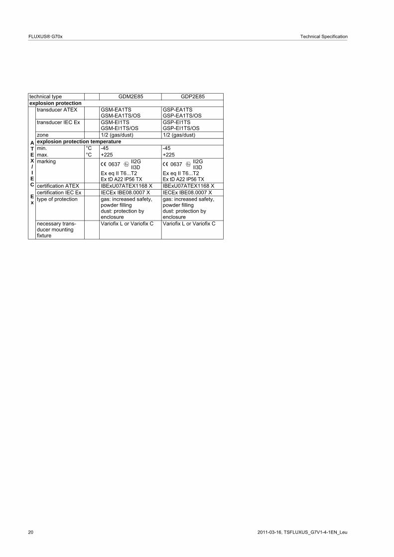
Shear Wave Transducers (zone 1, extended temperature range)
technical type GDM2E85 GDP2E85order code GSM-EA1TS
GSM-EA1TS/OSGSM-EI1TSGSM-EI1TS/OS
GSP-EA1TSGSP-EA1TS/OSGSP-EI1TSGSP-EI1TS/OS
transducer frequency MHz 1 2
medium pressure1
min. extended metal pipe: 20 metal pipe: 20min. metal pipe: 30
plastic pipe: 1metal pipe: 30plastic pipe: 1
inner pipe diameter d2
min. extended 30 15min. recommended 40 20max. recommended 80 40max. extended 120 60pipe wall thickness min. 2.5 1.5max. - -material housing PI with stainless steel
cap 304 (1.4301), option OS: 316L (1.4404)
PI with stainless steel cap 304 (1.4301), option OS: 316L (1.4404)
contact surface PI PIdegree of protection according to EN 60529
IP 56 IP 56
transducer cable type 6111 6111length 4 4dimensions length l 62.5 62.5width b 32 32height h 40.5 40.5dimensional drawing
operating temperature min. °C -30 -30max. °C +200 +200temperaturecompensation
x x
1 depending on application, typical absolute value for natural gas, nitrogen, compressed air 2 shear wave transducers:
typical values for natural gas, nitrogen, oxygen, pipe diameters for other gases on requestpipe diameter min. recommended/max. recommended/max. extended: in diagonal mode and for a flow velocity of
continued on next page
barbar
mmmmmmmm
mmmm
m
mmmmmm
l
hb
l
hb
15 m/s
20 2011-03-16, TSFLUXUS_G7V1-4-1EN_Leu
FLUXUS® G70x Technical Specification
explosion protection
ATEX/IEC
Ex
transducer ATEX GSM-EA1TSGSM-EA1TS/OS
GSP-EA1TSGSP-EA1TS/OS
transducer IEC Ex GSM-EI1TSGSM-EI1TS/OS
GSP-EI1TSGSP-EI1TS/OS
zone 1/2 (gas/dust) 1/2 (gas/dust)explosion protection temperature min. °C -45 -45max. °C +225 +225marking
Ex eq II T6...T2Ex tD A22 IP56 TX
Ex eq II T6...T2Ex tD A22 IP56 TX
certification ATEX IBExU07ATEX1168 X IBExU07ATEX1168 Xcertification IEC Ex IECEx IBE08.0007 X IECEx IBE08.0007 Xtype of protection gas: increased safety,
min. extended metal pipe: 20 metal pipe: 20min. metal pipe: 30
plastic pipe: 1metal pipe: 30plastic pipe: 1
inner pipe diameter d2
min. extended 250 70min. recommended 380 80max. recommended 810 500max. extended 1100 720pipe wall thickness min. 14 5max. - -material housing PEEK with stainless steel
cap 304 (1.4301), option OS: 316L (1.4404)
PEEK with stainless steel cap 304 (1.4301), option OS: 316L (1.4404)
contact surface PEEK PEEKdegree of protection according to EN 60529
IP 67 IP 67
transducer cable type 1699 1699length 5 5dimensions length l 129.5 126.5width b 51 51height h 67 67.5dimensional drawing
operating temperature min. °C -40 -40max. °C +130 +130temperaturecompensation
x x
1 depending on application, typical absolute value for natural gas, nitrogen, compressed air 2 shear wave transducers:
typical values for natural gas, nitrogen, oxygen, pipe diameters for other gases on requestpipe diameter min. recommended/max. recommended/max. extended: in diagonal mode and for a flow velocity of
continued on next page
barbar
mmmmmmmm
mmmm
m
mmmmmm
l
hb
l
hb
15 m/s
22 2011-03-16, TSFLUXUS_G7V1-4-1EN_Leu
FLUXUS® G70x Technical Specification
explosion protection
ATEX
transducer GSG-NA2TSGSG-NA2TS/OS
GSK-NA2TSGSK-NA2TS/OS
zone 2 2explosion protection temperature min. °C -55 -55max. °C +190 +190marking
II3G Ex nA II T6...T3Ta -55...+190 °CII3D Ex tD A22 IP67 TX
II3G Ex nA II T6...T3Ta -55...+190 °CII3D Ex tD A22 IP67 TX
certification - -type of protection gas: non sparking
dust: protection byenclosure
gas: non sparkingdust: protection byenclosure
necessary trans-ducer mountingfixture
Variofix L or Variofix C Variofix L or Variofix C
FM
transducer GSG-NF2TSGSG-NF2TS/OS
GSK-NF2TSGSK-NF2TS/OS
explosion protection temperature min. °C -40 -40max. °C +125 +125marking NI/Cl. I,II,III/Div. 2 /
GP A,B,C,D,E,F,G/Temp. Codes dwg 3860
NI/Cl. I,II,III/Div. 2 /GP A,B,C,D,E,F,G/
Temp. Codes dwg 3860type of protection non incendive non incendive
technical type GDG1N52 GDK1N52
TSFLUXUS_G7V1-4-1EN_Leu, 2011-03-16 23
Technical Specification FLUXUS® G70x
Shear Wave Transducers (ATEX zone 2, FM or without explosion protection)
technical type GDM2N52 GDP2N52order code GSM-NA2TS
min. extended metal pipe: 20 metal pipe: 20min. metal pipe: 30
plastic pipe: 1metal pipe: 30plastic pipe: 1
inner pipe diameter d2
min. extended 30 15min. recommended 40 20max. recommended 80 40max. extended 120 60pipe wall thickness min. 2.5 1.5max. - -material housing PEEK with stainless steel
cap 304 (1.4301), option OS: 316L (1.4404)
PEEK with stainless steel cap 304 (1.4301), option OS: 316L (1.4404)
contact surface PEEK PEEKdegree of protection according to EN 60529
IP 67 IP 65
transducer cable type 1699 1699length 4 4dimensions length l 62.5 62.5width b 32 32height h 40.5 40.5dimensional drawing
operating temperature min. °C -40 -40max. °C +130 +130temperaturecompensation
x x
1 depending on application, typical absolute value for natural gas, nitrogen, compressed air 2 shear wave transducers:
typical values for natural gas, nitrogen, oxygen, pipe diameters for other gases on requestpipe diameter min. recommended/max. recommended/max. extended: in diagonal mode and for a flow velocity of
continued on next page
barbar
mmmmmmmm
mmmm
m
mmmmmm
l
hb
l
hb
15 m/s
24 2011-03-16, TSFLUXUS_G7V1-4-1EN_Leu
FLUXUS® G70x Technical Specification
explosion protection
ATEX
transducer GSM-NA2TSGSM-NA2TS/OS
GSP-NA2TSGSP-NA2TS/OS
zone 2 2explosion protection temperature min. °C -55 -55max. °C +190 +190marking
II3G Ex nA II T6...T3Ta -55...+190 °CII3D Ex tD A22 IP67 TX
II3G Ex nA II T6...T3Ta -55...+190 °CII3D Ex tD A22 IP67 TX
certification - -type of protection gas: non sparking
dust: protection byenclosure
gas: non sparkingdust: protection byenclosure
necessary trans-ducer mountingfixture
Variofix L or Variofix C Variofix L or Variofix C
FM
transducer GSM-NF2TSGSM-NF2TS/OS
GSP-NF2TSGSP-NF2TS/OS
explosion protection temperature min. °C -55 -55max. °C +190 +190marking NI/Cl. I,II,III/Div. 2 /
GP A,B,C,D,E,F,G/Temp. Codes dwg 3860
NI/Cl. I,II,III/Div. 2 /GP A,B,C,D,E,F,G/
Temp. Codes dwg 3860type of protection non incendive non incendive
technical type GDM2N52 GDP2N52
TSFLUXUS_G7V1-4-1EN_Leu, 2011-03-16 25
Technical Specification FLUXUS® G70x
Shear Wave Transducers (ATEX zone 2 or without explosion protection, IP 68)
technical type GDG1LI8 GDK1LI8 GDM2LI8 GDP2LI8order code GSG-NA2TS/IP68
GSG-NNNTS/IP68GSK-NA2TS/IP68GSK-NNNTS/IP68
GSM-NA2TS/IP68GSM-NNNTS/IP68
GSP-NA2TS/IP68GSP-NNNTS/IP68
transducer frequency MHz 0.2 0.5 1 2
medium pressure1
min. extended metal pipe: 20 metal pipe: 20 metal pipe: 20 metal pipe: 20min. metal pipe: 30
cap 316Ti (1.4571)PEEK with stainless steel cap 316Ti (1.4571)
PEEK with stainless steel cap 316Ti (1.4571)
PEEK with stainless steel cap 316Ti (1.4571)
contact surface PEEK PEEK PEEK PEEKdegree of protection according to EN 60529
IP 68 IP 68 IP 68 IP 68
transducer cable type 2550 2550 2550 2550length 12 12 12 12dimensions length l 128.5 128.5 70 70width b 54 54 32 32height h 83.5 83.5 46 46dimensional drawing
operating temperature min. °C -40 -40 -40 -40max. °C +100 +100 +100 +100temperaturecompensation
x x x x
explosion protection
ATEX
transducer GSG-NA2TS/IP68 GSK-NA2TS/IP68 GSM-NA2TS/IP68 GSP-NA2TS/IP68zone 2 2 2 2explosion protection temperature min. °C -40 -40 -40 -40max. °C +90 +90 +90 +90marking
II3G Ex nA II T6...T5Ta -40...+90 °CII3D Ex tD A22 IP68 TX
II3GEx nA II T6...T5Ta -40...+90 °CII3D Ex tD A22 IP68 TX
II3G Ex nA II T6...T5Ta -40...+90 °CII3D Ex tD A22 IP68 TX
II3G Ex nA II T6...T5Ta -40...+90 °CII3D Ex tD A22 IP68 TX
certification - - - -type of protection gas: non sparking
dust: protection byenclosure
gas: non sparkingdust: protection byenclosure
gas: non sparkingdust: protection byenclosure
gas: non sparkingdust: protection byenclosure
necessary trans-ducer mountingfixture
Variofix L or Variofix C Variofix L or Variofix C Variofix L or Variofix C Variofix L or Variofix C
1 depending on application, typical absolute value for natural gas, nitrogen, compressed air 2 shear wave transducers:
typical values for natural gas, nitrogen, oxygen, pipe diameters for other gases on requestpipe diameter min. recommended/max. recommended/max. extended: in diagonal mode and for a flow
velocity of
barbar
mmmmmmmm
mmmm
m
mmmmmm
l
hb
l
hb
l
hb
l
hb
15 m/s
26 2011-03-16, TSFLUXUS_G7V1-4-1EN_Leu
FLUXUS® G70x Technical Specification
Shear Wave Transducers (connection system AS, without explosion protection)
technical type GDG1NZ7 GDK1NZ7order code GSG-NNNAS GSK-NNNAStransducer frequency MHz 0.2 0.5
medium pressure1
min. extended metal pipe: 20 metal pipe: 20min. metal pipe: 30
plastic pipe: 1metal pipe: 30plastic pipe: 1
inner pipe diameter d2
min. extended 250 70min. recommended 380 80max. recommended 810 500max. extended 1100 720pipe wall thickness min. 14 5max. - -material housing PEEK with stainless steel
cap 304 (1.4301)PEEK with stainless steel cap 304 (1.4301)
contact surface PEEK PEEKdegree of protection according to EN 60529
IP 67 IP 67
transducer cable type 1699 1699length 5 5dimensions length l 129.5 126.5width b 51 51height h 67 67.5dimensional drawing
operating temperature min. °C -40 -40max. °C +130 +130temperaturecompensation
x x
1 depending on application, typical absolute value for natural gas, nitrogen, compressed air 2 shear wave transducers:
typical values for natural gas, nitrogen, oxygen, pipe diameters for other gases on requestpipe diameter min. recommended/max. recommended/max. extended: in diagonal mode and for a flow velocity of
barbar
mmmmmmmm
mmmm
m
mmmmmm
l
hb
l
hb
15 m/s
TSFLUXUS_G7V1-4-1EN_Leu, 2011-03-16 27
Technical Specification FLUXUS® G70x
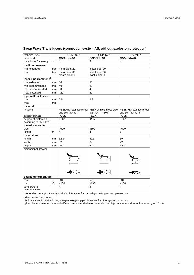
Shear Wave Transducers (connection system AS, without explosion protection)
technical type GDM2NZ7 GDP2NZ7 GDQ2NZ7order code GSM-NNNAS GSP-NNNAS GSQ-NNNAStransducer frequency MHz 1 2 4
medium pressure1
min. extended metal pipe: 20 metal pipe: 20min. metal pipe: 30
plastic pipe: 1metal pipe: 30plastic pipe: 1
inner pipe diameter d2
min. extended 30 15min. recommended 40 20max. recommended 80 40max. extended 120 60pipe wall thickness min. 2.5 1.5max. - -material housing PEEK with stainless steel
cap 304 (1.4301)PEEK with stainless steel cap 304 (1.4301)
PEEK with stainless steel cap 304 (1.4301)
contact surface PEEK PEEK PEEKdegree of protection according to EN 60529
IP 67 IP 67 IP 67
transducer cable type 1699 1699 1699length 4 4 3dimensions length l 62.5 62.5 39width b 32 32 22height h 40.5 40.5 25.5dimensional drawing
operating temperature min. °C -40 -40 -40max. °C +130 +130 +130temperaturecompensation
x x x
1 depending on application, typical absolute value for natural gas, nitrogen, compressed air 2 shear wave transducers:
typical values for natural gas, nitrogen, oxygen, pipe diameters for other gases on requestpipe diameter min. recommended/max. recommended/max. extended: in diagonal mode and for a flow velocity of
barbar
mmmmmmmm
mmmm
m
mmmmmm
l
hb
l
hb
hb
l
15 m/s
28 2011-03-16, TSFLUXUS_G7V1-4-1EN_Leu
FLUXUS® G70x Technical Specification
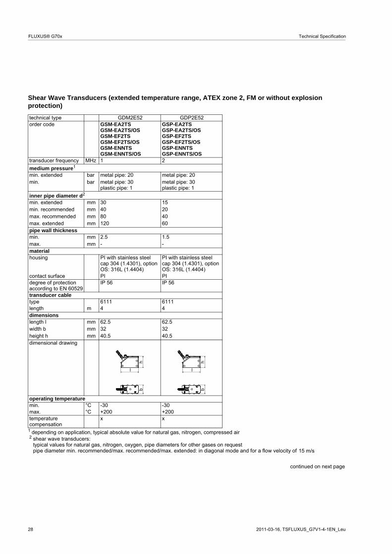
Shear Wave Transducers (extended temperature range, ATEX zone 2, FM or without explosionprotection)
technical type GDM2E52 GDP2E52order code GSM-EA2TS
min. extended metal pipe: 20 metal pipe: 20min. metal pipe: 30
plastic pipe: 1metal pipe: 30plastic pipe: 1
inner pipe diameter d2
min. extended 30 15min. recommended 40 20max. recommended 80 40max. extended 120 60pipe wall thickness min. 2.5 1.5max. - -material housing PI with stainless steel
cap 304 (1.4301), option OS: 316L (1.4404)
PI with stainless steel cap 304 (1.4301), option OS: 316L (1.4404)
contact surface PI PIdegree of protection according to EN 60529
IP 56 IP 56
transducer cable type 6111 6111length 4 4dimensions length l 62.5 62.5width b 32 32height h 40.5 40.5dimensional drawing
operating temperature min. °C -30 -30max. °C +200 +200temperaturecompensation
x x
1 depending on application, typical absolute value for natural gas, nitrogen, compressed air 2 shear wave transducers:
typical values for natural gas, nitrogen, oxygen, pipe diameters for other gases on requestpipe diameter min. recommended/max. recommended/max. extended: in diagonal mode and for a flow velocity of
continued on next page
barbar
mmmmmmmm
mmmm
m
mmmmmm
l
hb
l
hb
15 m/s
TSFLUXUS_G7V1-4-1EN_Leu, 2011-03-16 29
Technical Specification FLUXUS® G70x
explosion protection
ATEX
transducer GSM-EA2TSGSM-EA2TS/OS
GSP-EA2TSGSP-EA2TS/OS
zone 2 2explosion protection temperature min. °C -45 -45max. °C +235 +235marking
II3G Ex nA II T6...T2Ta -45...+235 °CII3D Ex tD A22 IP56 TX
II3G Ex nA II T6...T2Ta -45...+235 °CII3D Ex tD A22 IP56 TX
certification - -type of protection gas: non sparking
dust: protection byenclosure
gas: non sparkingdust: protection byenclosure
necessary trans-ducer mountingfixture
Variofix L or Variofix C Variofix L or Variofix C
FM
transducer GSM-EF2TSGSM-EF2TS/OS
GSP-EF2TSGSP-EF2TS/OS
explosion protection temperature min. °C -45 -45max. °C +235 +235marking NI/Cl. I,II,III/Div. 2 /
GP A,B,C,D,E,F,G/Temp. Codes dwg 3860
NI/Cl. I,II,III/Div. 2 /GP A,B,C,D,E,F,G/
Temp. Codes dwg 3860type of protection non incendive non incendive
technical type GDM2E52 GDP2E52
30 2011-03-16, TSFLUXUS_G7V1-4-1EN_Leu
FLUXUS® G70x Technical Specification
Shear Wave Transducers (extended temperature range, without explosion protection,connection system AS)
technical type GDM2EZ7 GDP2EZ7order code GSM-ENNAS GSP-ENNAStransducer frequency MHz 1 2
medium pressure1
min. extended metal pipe: 20 metal pipe: 20min. metal pipe: 30
plastic pipe: 1metal pipe: 30plastic pipe: 1
inner pipe diameter d2
min. extended 30 15min. recommended 40 20max. recommended 80 40max. extended 120 60pipe wall thickness min. 2.5 1.5max. - -material housing PI with stainless steel
cap 304 (1.4301)PI with stainless steel cap 304 (1.4301)
contact surface PI PIdegree of protection according to EN 60529
IP 65 IP 65
transducer cable type 6111 6111length 4 4dimensions length l 62.5 62.5width b 32 32height h 40.5 40.5dimensional drawing
operating temperature min. °C -30 -30max. °C +200 +200temperaturecompensation
x x
1 depending on application, typical absolute value for natural gas, nitrogen, compressed air 2 shear wave transducers:
typical values for natural gas, nitrogen, oxygen, pipe diameters for other gases on requestpipe diameter min. recommended/max. recommended/max. extended: in diagonal mode and for a flow velocity of
barbar
mmmmmmmm
mmmm
m
mmmmmm
l
hb
l
hb
15 m/s
TSFLUXUS_G7V1-4-1EN_Leu, 2011-03-16 31
Technical Specification FLUXUS® G70x
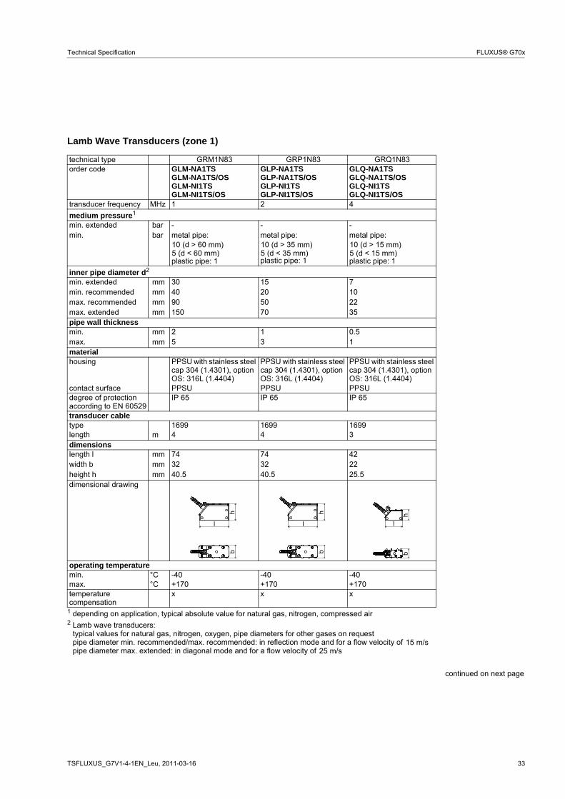
Lamb Wave Transducers (zone 1)
technical type GRG1N83 GRH1N83 GRK1N83order code GLG-NA1TS
GLG-NA1TS/OSGLG-NI1TSGLG-NI1TS/OS
GLH-NA1TSGLH-NA1TS/OSGLH-NI1TSGLH-NI1TS/OS
GLK-NA1TSGLK-NA1TS/OSGLK-NI1TSGLK-NI1TS/OS
transducer frequency MHz 0.2 0.3 0.5
medium pressure1
min. extended metal pipe: 10 metal pipe: 10 metal pipe:
PPSU with stainless steel cap 304 (1.4301), option OS: 316L (1.4404)
PPSU with stainless steel cap 304 (1.4301), option OS: 316L (1.4404)
contact surface PPSU PPSU PPSUdegree of protection according to EN 60529
IP 65 IP 65 IP 65
transducer cable type 1699 1699 1699length 5 5 5dimensions length l 128.5 128.5 128.5width b 51 51 51height h 67.5 67.5 67.5dimensional drawing
operating temperature min. °C -40 -40 -40max. °C +170 +170 +170temperaturecompensation
x x x
1 depending on application, typical absolute value for natural gas, nitrogen, compressed air 2 Lamb wave transducers:
typical values for natural gas, nitrogen, oxygen, pipe diameters for other gases on requestpipe diameter min. recommended/max. recommended: in reflection mode and for a flow velocity of pipe diameter max. extended: in diagonal mode and for a flow velocity of
continued on next page
bar10 (d > 120 mm)5 (d < 120 mm)
bar15 (d > 120 mm)10 (d < 120 mm)
mmmmmmmm
mmmm
m
mmmmmm
l
hb
l
hb
l
hb
15 m/s25 m/s
32 2011-03-16, TSFLUXUS_G7V1-4-1EN_Leu
FLUXUS® G70x Technical Specification
explosion protection
ATEX/IEC
Ex
transducer ATEX GLG-NA1TSGLG-NA1TS/OS
GLH-NA1TSGLH-NA1TS/OS
GLK-NA1TSGLK-NA1TS/OS
transducer IEC Ex GLG-NI1TSGLG-NI1TS/OS
GLH-NI1TSGLH-NI1TS/OS
GLK-NI1TSGLK-NI1TS/OS
zone 1 1 1explosion protection temperature min. °C -55 -55 -55max. °C +140 +140 +140marking
Ex eq II T6...T3Ex tD A21 IP65 TX
Ex eq II T6...T3Ex tD A21 IP65 TX
Ex eq II T6...T3Ex tD A21 IP65 TX
certification ATEX IBExU07ATEX1168 X IBExU07ATEX1168 X IBExU07ATEX1168 Xcertification IEC Ex IECEx IBE08.0007 X IECEx IBE08.0007 X IECEx IBE08.0007 Xtype of protection gas: increased safety,
PPSU with stainless steel cap 304 (1.4301), option OS: 316L (1.4404)
PPSU with stainless steel cap 304 (1.4301), option OS: 316L (1.4404)
contact surface PPSU PPSU PPSUdegree of protection according to EN 60529
IP 65 IP 65 IP 65
transducer cable type 1699 1699 1699length 4 4 3dimensions length l 74 74 42width b 32 32 22height h 40.5 40.5 25.5dimensional drawing
operating temperature min. °C -40 -40 -40max. °C +170 +170 +170temperaturecompensation
x x x
1 depending on application, typical absolute value for natural gas, nitrogen, compressed air 2 Lamb wave transducers:
typical values for natural gas, nitrogen, oxygen, pipe diameters for other gases on requestpipe diameter min. recommended/max. recommended: in reflection mode and for a flow velocity of pipe diameter max. extended: in diagonal mode and for a flow velocity of
continued on next page
barbar
10 (d > 60 mm)5 (d < 60 mm)
10 (d > 35 mm)5 (d < 35 mm)
10 (d > 15 mm)5 (d < 15 mm)
mmmmmmmm
mmmm
m
mmmmmm
l
hb
l
hb
l
hb
15 m/s25 m/s
34 2011-03-16, TSFLUXUS_G7V1-4-1EN_Leu
FLUXUS® G70x Technical Specification
explosion protection
ATEX/IEC
Ex
transducer ATEX GLM-NA1TSGLM-NA1TS/OS
GLP-NA1TSGLP-NA1TS/OS
GLQ-NA1TSGLQ-NA1TS/OS
transducer IEC Ex GLM-NI1TSGLM-NI1TS/OS
GLP-NI1TSGLP-NI1TS/OS
GLQ-NI1TSGLQ-NI1TS/OS
zone 1 1 1explosion protection temperature min. °C -55 -55 -55max. °C +140 +140 +140marking
Ex eq II T6...T3Ex tD A21 IP65 TX
Ex eq II T6...T3Ex tD A21 IP65 TX
Ex eq II T6...T3Ex tD A21 IP65 TX
certification ATEX IBExU07ATEX1168 X IBExU07ATEX1168 X IBExU07ATEX1168 Xcertification IEC Ex IECEx IBE08.0007 X IECEx IBE08.0007 X IECEx IBE08.0007 Xtype of protection gas: increased safety,
Variofix L or Variofix C Variofix L or Variofix C Variofix L or Variofix C
remark on request
technical type GRM1N83 GRP1N83 GRQ1N83
II2GII2D
0637 II2GII2D
0637 II2GII2D
0637
TSFLUXUS_G7V1-4-1EN_Leu, 2011-03-16 35
Technical Specification FLUXUS® G70x
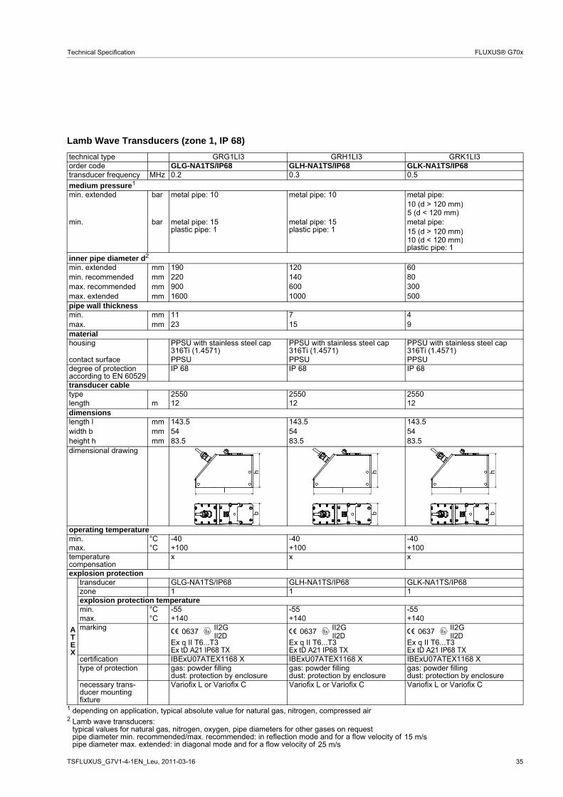
Lamb Wave Transducers (zone 1, IP 68)
technical type GRG1LI3 GRH1LI3 GRK1LI3order code GLG-NA1TS/IP68 GLH-NA1TS/IP68 GLK-NA1TS/IP68transducer frequency MHz 0.2 0.3 0.5
medium pressure1
min. extended metal pipe: 10 metal pipe: 10 metal pipe:
min. metal pipe: 15plastic pipe: 1
metal pipe: 15plastic pipe: 1
metal pipe:
plastic pipe: 1
inner pipe diameter d2
min. extended 190 120 60min. recommended 220 140 80max. recommended 900 600 300max. extended 1600 1000 500pipe wall thickness min. 11 7 4max. 23 15 9material housing PPSU with stainless steel cap
316Ti (1.4571)PPSU with stainless steel cap 316Ti (1.4571)
PPSU with stainless steel cap 316Ti (1.4571)
contact surface PPSU PPSU PPSUdegree of protection according to EN 60529
IP 68 IP 68 IP 68
transducer cable type 2550 2550 2550length 12 12 12dimensions length l 143.5 143.5 143.5width b 54 54 54height h 83.5 83.5 83.5dimensional drawing
operating temperature min. °C -40 -40 -40max. °C +100 +100 +100temperaturecompensation
x x x
explosion protection
ATEX
transducer GLG-NA1TS/IP68 GLH-NA1TS/IP68 GLK-NA1TS/IP68zone 1 1 1explosion protection temperature min. °C -55 -55 -55max. °C +140 +140 +140marking
Ex q II T6...T3Ex tD A21 IP68 TX
Ex q II T6...T3Ex tD A21 IP68 TX
Ex q II T6...T3Ex tD A21 IP68 TX
certification IBExU07ATEX1168 X IBExU07ATEX1168 X IBExU07ATEX1168 Xtype of protection gas: powder filling
dust: protection by enclosuregas: powder fillingdust: protection by enclosure
gas: powder fillingdust: protection by enclosure
necessary trans-ducer mountingfixture
Variofix L or Variofix C Variofix L or Variofix C Variofix L or Variofix C
1 depending on application, typical absolute value for natural gas, nitrogen, compressed air 2 Lamb wave transducers:
typical values for natural gas, nitrogen, oxygen, pipe diameters for other gases on requestpipe diameter min. recommended/max. recommended: in reflection mode and for a flow velocity of pipe diameter max. extended: in diagonal mode and for a flow velocity of
bar10 (d > 120 mm)5 (d < 120 mm)
bar15 (d > 120 mm)10 (d < 120 mm)
mmmmmmmm
mmmm
m
mmmmmm
l
hb
l
hb
lh
b
II2GII2D
0637 II2GII2D
0637 II2GII2D
0637
15 m/s25 m/s
36 2011-03-16, TSFLUXUS_G7V1-4-1EN_Leu
FLUXUS® G70x Technical Specification
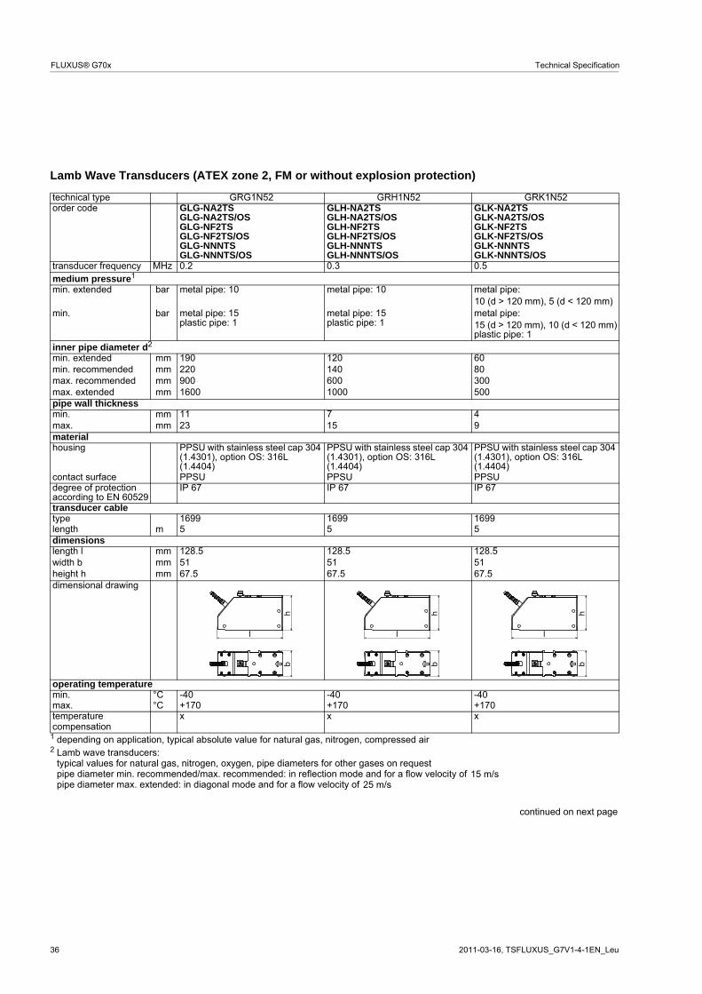
Lamb Wave Transducers (ATEX zone 2, FM or without explosion protection)
technical type GRG1N52 GRH1N52 GRK1N52order code GLG-NA2TS
transducer frequency MHz 0.2 0.3 0.5medium pressure1
min. extended metal pipe: 10 metal pipe: 10 metal pipe:
min. metal pipe: 15plastic pipe: 1
metal pipe: 15plastic pipe: 1
metal pipe:
plastic pipe: 1inner pipe diameter d2
min. extended 190 120 60min. recommended 220 140 80max. recommended 900 600 300max. extended 1600 1000 500pipe wall thickness min. 11 7 4max. 23 15 9material housing PPSU with stainless steel cap 304
(1.4301), option OS: 316L (1.4404)
PPSU with stainless steel cap 304 (1.4301), option OS: 316L (1.4404)
PPSU with stainless steel cap 304 (1.4301), option OS: 316L (1.4404)
contact surface PPSU PPSU PPSUdegree of protection according to EN 60529
IP 67 IP 67 IP 67
transducer cable type 1699 1699 1699length 5 5 5dimensions length l 128.5 128.5 128.5width b 51 51 51height h 67.5 67.5 67.5dimensional drawing
operating temperature min. °C -40 -40 -40max. °C +170 +170 +170temperaturecompensation
x x x
1 depending on application, typical absolute value for natural gas, nitrogen, compressed air 2 Lamb wave transducers:
typical values for natural gas, nitrogen, oxygen, pipe diameters for other gases on requestpipe diameter min. recommended/max. recommended: in reflection mode and for a flow velocity of pipe diameter max. extended: in diagonal mode and for a flow velocity of
continued on next page
bar10 (d > 120 mm), 5 (d < 120 mm)
bar15 (d > 120 mm), 10 (d < 120 mm)
mmmmmmmm
mmmm
m
mmmmmm
l
hb
l
hb
l
hb
15 m/s25 m/s
TSFLUXUS_G7V1-4-1EN_Leu, 2011-03-16 37
Technical Specification FLUXUS® G70x
explosion protection
ATEX
transducer GLG-NA2TSGLG-NA2TS/OS
GLH-NA2TSGLH-NA2TS/OS
GLK-NA2TSGLK-NA2TS/OS
zone 2 2 2explosion protection temperature min. °C -55 -55 -55max. °C +150 +150 +150marking
II3G Ex nA II T6...T3Ta -55...+150 °CII3D Ex tD A22 IP67 TX
II3G Ex nA II T6...T3Ta -55...+150 °CII3D Ex tD A22 IP67 TX
II3G Ex nA II T6...T3Ta -55...+150 °CII3D Ex tD A22 IP67 TX
certification - - -type of protection gas: non sparking
dust: protection by enclosuregas: non sparkingdust: protection by enclosure
gas: non sparkingdust: protection by enclosure
necessary trans-ducer mountingfixture
Variofix L or Variofix C Variofix L or Variofix C Variofix L or Variofix C
FM
transducer GLG-NF2TSGLG-NF2TS/OS
GLH-NF2TSGLH-NF2TS/OS
GLK-NF2TSGLK-NF2TS/OS
explosion protection temperature min. °C -40 -40 -40max. °C +165 +165 +165marking NI/Cl. I,II,III/Div. 2 /
GP A,B,C,D,E,F,G/Temp. Codes dwg 3860
NI/Cl. I,II,III/Div. 2 /GP A,B,C,D,E,F,G/
Temp. Codes dwg 3860
NI/Cl. I,II,III/Div. 2 /GP A,B,C,D,E,F,G/
Temp. Codes dwg 3860type of protection non incendive non incendive non incendive
technical type GRG1N52 GRH1N52 GRK1N52
38 2011-03-16, TSFLUXUS_G7V1-4-1EN_Leu
FLUXUS® G70x Technical Specification
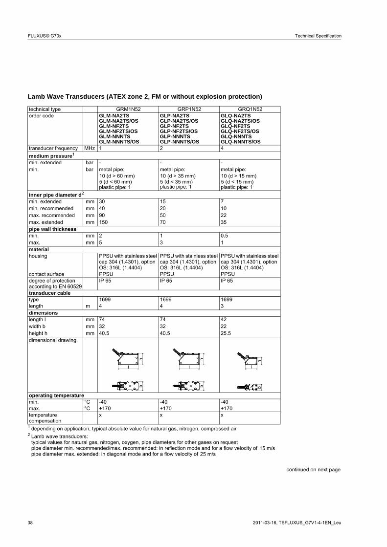
Lamb Wave Transducers (ATEX zone 2, FM or without explosion protection)
technical type GRM1N52 GRP1N52 GRQ1N52order code GLM-NA2TS
PPSU with stainless steel cap 304 (1.4301), option OS: 316L (1.4404)
PPSU with stainless steel cap 304 (1.4301), option OS: 316L (1.4404)
contact surface PPSU PPSU PPSUdegree of protection according to EN 60529
IP 65 IP 65 IP 65
transducer cable type 1699 1699 1699length 4 4 3dimensions length l 74 74 42width b 32 32 22height h 40.5 40.5 25.5dimensional drawing
operating temperature min. °C -40 -40 -40max. °C +170 +170 +170temperaturecompensation
x x x
1 depending on application, typical absolute value for natural gas, nitrogen, compressed air 2 Lamb wave transducers:
typical values for natural gas, nitrogen, oxygen, pipe diameters for other gases on requestpipe diameter min. recommended/max. recommended: in reflection mode and for a flow velocity of pipe diameter max. extended: in diagonal mode and for a flow velocity of
continued on next page
barbar
10 (d > 60 mm)5 (d < 60 mm)
10 (d > 35 mm)5 (d < 35 mm)
10 (d > 15 mm)5 (d < 15 mm)
mmmmmmmm
mmmm
m
mmmmmm
l
hb
l
hb
l
hb
15 m/s25 m/s
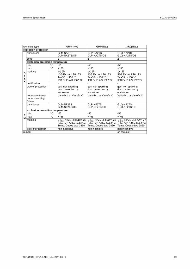
TSFLUXUS_G7V1-4-1EN_Leu, 2011-03-16 39
Technical Specification FLUXUS® G70x
explosion protection
ATEX
transducer GLM-NA2TSGLM-NA2TS/OS
GLP-NA2TSGLP-NA2TS/OS
GLQ-NA2TSGLQ-NA2TS/OS
zone 2 2 2explosion protection temperature min. °C -55 -55 -55max. °C +150 +150 +150marking
II3G Ex nA II T6...T3Ta -55...+150 °CII3D Ex tD A22 IP67 TX
II3G Ex nA II T6...T3Ta -55...+150 °CII3D Ex tD A22 IP67 TX
II3G Ex nA II T6...T3Ta -55...+150 °CII3D Ex tD A22 IP67 TX
certification - - -type of protection gas: non sparking
dust: protection byenclosure
gas: non sparkingdust: protection byenclosure
gas: non sparkingdust: protection byenclosure
necessary trans-ducer mountingfixture
Variofix L or Variofix C Variofix L or Variofix C Variofix L or Variofix C
FM
transducer GLM-NF2TSGLM-NF2TS/OS
GLP-NF2TSGLP-NF2TS/OS
GLQ-NF2TSGLQ-NF2TS/OS
explosion protection temperature min. °C -55 -55 -55max. °C +165 +165 +165marking NI/Cl. I,II,III/Div. 2 /
GP A,B,C,D,E,F,G/Temp. Codes dwg 3860
NI/Cl. I,II,III/Div. 2 /GP A,B,C,D,E,F,G/
Temp. Codes dwg 3860
NI/Cl. I,II,III/Div. 2 /GP A,B,C,D,E,F,G/
Temp. Codes dwg 3860type of protection non incendive non incendive non incendive
remark on request
technical type GRM1N52 GRP1N52 GRQ1N52
40 2011-03-16, TSFLUXUS_G7V1-4-1EN_Leu
FLUXUS® G70x Technical Specification
Lamb Wave Transducers (ATEX zone 2 or without explosion protection, IP 68)
technical type GRG1LI8 GRH1LI8 GRK1LI8order code GLG-NA2TS/IP68
GLG-NNNTS/IP68GLH-NA2TS/IP68GLH-NNNTS/IP68
GLK-NA2TS/IP68GLK-NNNTS/IP68
transducer frequency MHz 0.2 0.3 0.5medium pressure1
min. extended metal pipe: 10 metal pipe: 10 metal pipe:
min. metal pipe: 15plastic pipe: 1
metal pipe: 15plastic pipe: 1
metal pipe:
plastic pipe: 1inner pipe diameter d2
min. extended 190 120 60min. recommended 220 140 80max. recommended 900 600 300max. extended 1600 1000 500pipe wall thickness min. 11 7 4max. 23 15 9material housing PPSU with stainless steel cap
316Ti (1.4571)PPSU with stainless steel cap 316Ti (1.4571)
PPSU with stainless steel cap 316Ti (1.4571)
contact surface PPSU PPSU PPSUdegree of protection according to EN 60529
IP 68 IP 68 IP 68
transducer cable type 2550 2550 2550length 12 12 12dimensions length l 143.5 143.5 143.5width b 54 54 54height h 83.5 83.5 83.5dimensional drawing
operating temperature min. °C -40 -40 -40max. °C +100 +100 +100temperaturecompensation
x x x
explosion protection
ATEX
transducer GLG-NA2TS/IP68 GLH-NA2TS/IP68 GLK-NA2TS/IP68zone 2 2 2explosion protection temperature min. °C -40 -40 -40max. °C +90 +90 +90marking
II3G Ex nA II T6...T5Ta -40...+90 °CII3D Ex tD A22 IP68 TX
II3G Ex nA II T6...T5Ta -40...+90 °CII3D Ex tD A22 IP68 TX
II3G Ex nA II T6...T5Ta -40...+90 °CII3D Ex tD A22 IP68 TX
certification - - -type of protection gas: non sparking
dust: protection by enclosuregas: non sparkingdust: protection by enclosure
gas: non sparkingdust: protection by enclosure
necessary trans-ducer mountingfixture
Variofix L or Variofix C Variofix L or Variofix C Variofix L or Variofix C
1 depending on application, typical absolute value for natural gas, nitrogen, compressed air 2 Lamb wave transducers:
typical values for natural gas, nitrogen, oxygen, pipe diameters for other gases on requestpipe diameter min. recommended/max. recommended: in reflection mode and for a flow velocity of pipe diameter max. extended: in diagonal mode and for a flow velocity of
bar10 (d > 120 mm)5 (d < 120 mm)
bar15 (d > 120 mm)10 (d < 120 mm)
mmmmmmmm
mmmm
m
mmmmmm
l
hb
15 m/s25 m/s
TSFLUXUS_G7V1-4-1EN_Leu, 2011-03-16 41
Technical Specification FLUXUS® G70x
Lamb Wave Transducers (without explosion protection, with connection system AS)
technical type GRG1NC3 GRH1NC3 GRK1NC3order code GLG-NNNAS GLH-NNNAS GLK-NNNAStransducer frequency MHz 0.2 0.3 0.5
medium pressure1
min. extended metal pipe: 10 metal pipe: 10 metal pipe:
cap 304 (1.4301)PPSU with stainless steel cap 304 (1.4301)
PPSU with stainless steel cap 304 (1.4301)
contact surface PPSU PPSU PPSUdegree of protection according to EN 60529
IP 65 IP 65 IP 65
transducer cable type 1699 1699 1699length 5 5 5dimensions length l 128.5 128.5 128.5width b 51 51 51height h 67.5 67.5 67.5dimensional drawing
operating temperature min. °C -40 -40 -40max. °C +170 +170 +170temperaturecompensation
x x x
1 depending on application, typical absolute value for natural gas, nitrogen, compressed air 2 Lamb wave transducers:
typical values for natural gas, nitrogen, oxygen, pipe diameters for other gases on requestpipe diameter min. recommended/max. recommended: in reflection mode and for a flow velocity of pipe diameter max. extended: in diagonal mode and for a flow velocity of
bar10 (d > 120 mm)5 (d < 120 mm)
bar15 (d > 120 mm)10 (d < 120 mm)
mmmmmmmm
mmmm
m
mmmmmm
l
hb
l
hb
l
hb
15 m/s25 m/s
42 2011-03-16, TSFLUXUS_G7V1-4-1EN_Leu
FLUXUS® G70x Technical Specification
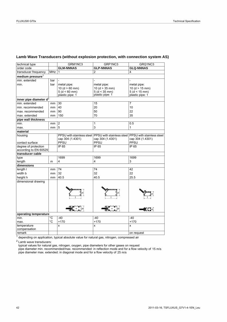
Lamb Wave Transducers (without explosion protection, with connection system AS)
technical type GRM1NC3 GRP1NC3 GRQ1NC3order code GLM-NNNAS GLP-NNNAS GLQ-NNNAStransducer frequency MHz 1 2 4
cap 304 (1.4301)PPSU with stainless steel cap 304 (1.4301)
PPSU with stainless steel cap 304 (1.4301)
contact surface PPSU PPSU PPSUdegree of protection according to EN 60529
IP 65 IP 65 IP 65
transducer cable type 1699 1699 1699length 4 4 3dimensions length l 74 74 42width b 32 32 22height h 40.5 40.5 25.5dimensional drawing
operating temperature min. °C -40 -40 -40max. °C +170 +170 +170temperaturecompensation
x x x
remark on request 1 depending on application, typical absolute value for natural gas, nitrogen, compressed air 2 Lamb wave transducers:
typical values for natural gas, nitrogen, oxygen, pipe diameters for other gases on requestpipe diameter min. recommended/max. recommended: in reflection mode and for a flow velocity of pipe diameter max. extended: in diagonal mode and for a flow velocity of
barbar
10 (d > 60 mm)5 (d < 60 mm)
10 (d > 35 mm)5 (d < 35 mm)
10 (d > 15 mm)5 (d < 15 mm)
mmmmmmmm
mmmm
m
mmmmmm
l
hb
l
hb
l
hb
15 m/s25 m/s
TSFLUXUS_G7V1-4-1EN_Leu, 2011-03-16 43
Technical Specification FLUXUS® G70x
Transducer Mounting Fixtures
Order Codes
1, 2 3 4 5 6 7...9 10, 11 no. of character
tra
nsdu
cer
mou
ntin
g fix
ture
tra
nsdu
cer
- mea
surin
g m
ode
size
- fixat
ion
oute
r pi
pe
diam
eter
/ optio
n
description
VL Variofix L
VС Variofix C
K transducers with transducer frequency G, H, K
M transducers with transducer frequency M, P
Q transducers with transducer frequency Q
D reflection mode or diagonal mode
R reflection mode
S small
M medium
L large
S tension straps
W welding
N without fixation
002 10...20 mm
004 20...40 mm
T36 40...360 mm
013 10...130 mm
036 130...360 mm
092 360...920 mm
200 920...2000 mm
IP68 degree of protection IP 68
OS housing with stainless steel 316
Z special design
example
VL K - D S - S 200 Variofix L and tension straps for transducers with transducer fre-quency G, H, K
VLK: 348 mm,option IP68: 368 mmVLM: 234 mmVLQ: 176 mm
VLK: 423 x 90 x 93 mm,option IP68: 443 x 94 x 105 mmVLM: 309 x 57 x 63 mmVLQ: 247 x 43 x 47 mm
VCK-xL: 500 mm,VCK-xS: 350 mm,VCM: 400 mmVCQ: 250 mm
VCK-xL: 560 x 122 x 102 mm,option IP68: 560 x 126 x 120 mmVCK-xS: 410 x 122 x 102 mm,option IP68: 410 x 126 x 120 mmVCM: 460 x 96 x 80 mmVCQ: 310 x 85 x 62 mm
TSFLUXUS_G7V1-4-1EN_Leu, 2011-03-16 45
Technical Specification FLUXUS® G70x
Coupling Materials for Transducers
Technical Data
normal temperature range(4th character of transducer order code = N)
extended temperature range(4th character of transducer order code = E)
< 100 °C 100...170 °C < 150 °C 150...200 °C
< 2 h coupling compound type N coupling compound type E coupling compound type E coupling compound type E or H
< 24 h coupling compound type N coupling compound type E coupling compound type E coupling foil type VT
long time measure-ment
indoor coupling compound type N coupling compound type E coupling foil type VT1 coupling foil type VT2
outdoor coupling foil type VT coupling foil type VT coupling foil type VT1 coupling foil type VT2
1 < 5 years2 < 6 months
type order code temperature material remark °C
coupling compoundtype N
990739-1 -30...+130 mineral grease paste
coupling compoundtype E
990739-2 -30...+200 silicone paste
coupling compoundtype H
990739-3 -30...+250 fluoropolymer paste
coupling foil type VT 990739-0 -10...+150,peak max. 200
fluoroelastomer for transducers with transducer frequency G, H, K
990739-6 for shear wave transducers with transducer frequency M, P
990739-14 for IP 68 shear wave transducers and Lambwave transducers with transducer frequency M, P
990739-15 for shear wave transducers with transducer frequency Q
990739-5 for Lambwave transducers with transducer frequency Q
46 2011-03-16, TSFLUXUS_G7V1-4-1EN_Leu
FLUXUS® G70x Technical Specification
Damping Mats (optional)Damping mats will be used for the gas measurement to reduce noise influences on the measurement.
Transducer damping mats will be installed below the transducers.
Pipe damping mats will be installed at reflection points, e.g. flange, weld.
Selection of Damping Mats type description outer pipe
diameterdimensions
l x b x htransducerfrequency
(3rd character of transducer order
code)
techni-cal type
temperature remark
G H K M P °Ctransducer damping mat C self-adhesive, for stationary
installation < 80 450 x 115 x 0.5 - - - x x C20S3 -25...+60 80 900 x 230 x 0.5 - - x x - C20S2
900 x 230 x 1.3 x x - - - C50S2pipe damping mat B self-adhesive, for stationary
installation l x 100 x 0.9 x x x x x B35R2 -35...+50 l - see table below
Length of Pipe Damping Mat - Type B(length l depending on transducer frequency and outer pipe diameter)
outer pipe diameter D transducer frequency G, H K, M, P
100 2 1200 6 3300 12 6500 32 161000 126 63
b
lD
transducer damping mat pipe damping mat
reflection mode diagonal mode
D - outer pipe diameter
reflection point
mm mm
mm m m
TSFLUXUS_G7V1-4-1EN_Leu, 2011-03-16 47
Technical Specification FLUXUS® G70x
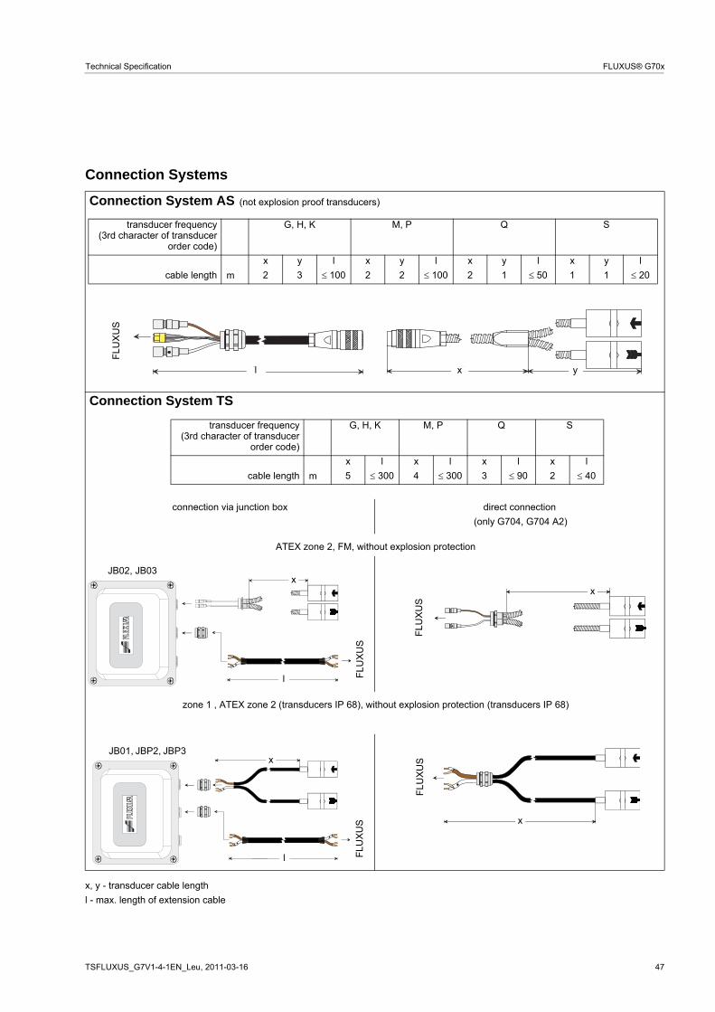
Connection Systems
x, y - transducer cable length
l - max. length of extension cable
Connection System AS
Connection System TS
connection via junction box direct connection
(not explosion proof transducers)
transducer frequency(3rd character of transducer
order code)
G, H, K M, P Q S
x y l x y l x y l x y l
cable length 2 3 100 2 2 100 2 1 50 1 1 20m
FLU
XU
S
xl y
transducer frequency(3rd character of transducer
order code)
G, H, K M, P Q S
x l x l x l x l
cable length 5 300 4 300 3 90 2 40m
(only G704, G704 A2)
ATEX zone 2, FM, without explosion protection
LX
FLU
XU
S
l
xJB02, JB03
X
FLU
XU
S
x
zone 1 , ATEX zone 2 (transducers IP 68), without explosion protection (transducers IP 68)
L
X
FLU
XU
S
l
xJB01, JBP2, JBP3
X
FLU
XU
S
x
48 2011-03-16, TSFLUXUS_G7V1-4-1EN_Leu
FLUXUS® G70x Technical Specification
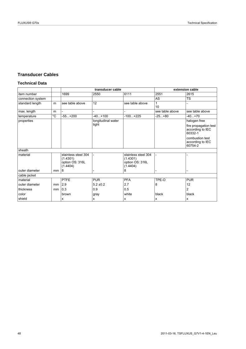
Transducer Cables
Technical Data
transducer cable extension cable item number 1699 2550 6111 2551 2615connection system AS TSstandard length see table above 12 see table above
10-
max. length - - - see table above see table above
temperature °C -55...+200 -40...+100 -100...+225 -25...+80 -40...+70properties longitudinal water