TECHNICAL SPECIFICATION Nº I-ET-3010.00-5140-741-P4X-001 CLIENT: SHEET: 1 of 42 JOB: - AREA: DP&T SRGE TITLE: LOW-VOLTAGE MOTOR CONTROL CENTER AND SWITCHGEAR FOR OFFSHORE UNITS NP-1 ESUP MICROSOFT WORD / V. 2003 / I-ET-3010.00-5140-741-P4X-001_C INDEX OF REVISIONS REV. DESCRIPTION AND/OR REVISED SHEETS 0 A B C ORIGINAL ISSUE REVISED WHERE INDICATED GENERAL REVIEW ACCORDING TO IOGP JIP 33-SUPPLEMENTARY REQUIREMENTS TO IEC 61439-1 & 2 LV SWITCHGEAR & CONTROLGEAR, VERSION 2, NOVEMBER 2016 REVISED ITEM 2.4 REV. 0 REV. A REV. B REV. C REV. D REV. E REV. F REV. G REV. H DATE SEP/04/18 DEC/11/19 MAR/03/20 APR/14/20 DESIGN ESUP ESUP ESUP ESUP EXECUTION FABIO.P MAFRA ESPOSTE ESPOSTE CHECK ESPOSTE FABIO.P TAVES TAVES APPROVAL MATTOSO REGGIANI REGGIANI REGGIANI INFORMATION IN THIS DOCUMENT IS PROPERTY OF PETROBRAS, BEING PROHIBITED OUTSIDE OF THEIR PURPOSE FORM OWNED TO PETROBRAS N-381 REV. L
Transcript
TECHNICAL SPECIFICATION Nº
I-ET-3010.00-5140-741-P4X-001 CLIENT:
SHEET:
1 of
42 JOB:
-
AREA:
DP&T SRGE
TITLE:
LOW-VOLTAGE MOTOR CONTROL CENTER AND SWITCHGEAR FOR OFFSHORE UNITS
NP-1
ESUP
MICROSOFT WORD / V. 2003 / I-ET-3010.00-5140-741-P4X-001_C
INDEX OF REVISIONS
REV. DESCRIPTION AND/OR REVISED SHEETS
0
A
B
C
ORIGINAL ISSUE
REVISED WHERE INDICATED
GENERAL REVIEW ACCORDING TO IOGP JIP 33-SUPPLEMENTARY
REQUIREMENTS TO IEC 61439-1 & 2 LV SWITCHGEAR & CONTROLGEAR,
VERSION 2, NOVEMBER 2016
REVISED ITEM 2.4
REV. 0 REV. A REV. B REV. C REV. D REV. E REV. F REV. G REV. H
DATE SEP/04/18 DEC/11/19 MAR/03/20 APR/14/20
DESIGN ESUP ESUP ESUP ESUP
EXECUTION FABIO.P MAFRA ESPOSTE ESPOSTE
CHECK ESPOSTE FABIO.P TAVES TAVES
APPROVAL MATTOSO REGGIANI REGGIANI REGGIANI
INFORMATION IN THIS DOCUMENT IS PROPERTY OF PETROBRAS, BEING PROHIBITED OUTSIDE OF THEIR PURPOSE
FORM OWNED TO PETROBRAS N-381 REV. L
TECHNICAL SPECIFICATION Nº.
I-ET-3010.00-5140-741-P4X-001 REV. C
AREA: SHEET: 2
of 42
TITLE:
LOW-VOLTAGE MOTOR CONTROL CENTER AND SWITCHGEAR FOR OFFSHORE UNITS
4.1 GENERAL REQUIREMENTS .................................................................................................................................. 6
4.2 SPARE DRAWERS AND FUNCTIONAL UNITS ......................................................................................................... 6
4.3 ENVIRONMENTAL CONDITIONS, INCLINATION REQUIREMENTS AND VIBRATION REQUIREMENTS ...................... 7
4.4 CLASSIFICATION OF ASSEMBLIES ........................................................................................................................ 7
4.12 FUNCTIONAL UNITS .......................................................................................................................................... 15
4.19 CONTROL VOLTAGES ........................................................................................................................................ 32
6. PACKAGE AND TRANSPORT ............................................................................................................. 37
7. INSPECTION AND TESTS.................................................................................................................... 37
7.1 GENERAL .......................................................................................................................................................... 37
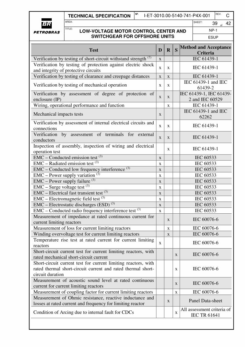
7.4 SPECIAL TESTS .................................................................................................................................................. 38
8. TRAINING .............................................................................................................................................. 40
9. SPARE PARTS AND TOOLS ................................................................................................................ 41
10. DATA SHEETS FORMS ........................................................................................................................ 41
11. ABBREVIATIONS AND ACRONYMS ................................................................................................... 41
LOW-VOLTAGE MOTOR CONTROL CENTER AND SWITCHGEAR FOR OFFSHORE UNITS
NP-1
ESUP
1. OBJECTIVE
This specification establishes the technical requirements for the design, construction, and tests of Low-Voltage Motor Control Centers (MCCs), as defined at IEEE 1683 and Low-Voltage Switchgears (CDCs), as defined at IEC 61439 for Offshore Units.
2. REFERENCE DOCUMENTS, STANDARDS AND CODES
Panel design shall comply with requirements of Classification Society, Brazilian Legislation, applicable regulatory rules and Supplementary Requirements to IEC 61439-1 & 2 LV Switchgear & Controlgear (version 2.0, November 2016) which is attached at this specification. At the design development and for equipment specification, this technical Specification shall be complied with. Exceptionally, where it is clearly justifiable, the ANSI, NEMA, IEEE, VDE and other internationally recognized standards may be used. Their use shall be restricted to specific cases and approved by PETROBRAS.
2.1 Complementary PETROBRAS Documents
The following documents shall be issued by Petrobras and used to get complementary information
[1] I-ET-3010.00-5140-700-P4X-001 - SPECIFICATION FOR ELECTRICAL DESIGN FOR OFFSHORE UNITS
[2] I-ET-3010.00-5140-700-P4X-002 - SPECIFICATION FOR ELECTRICAL MATERIAL AND EQUIPMENT FOR OFFSHORE UNITS
[3] I-ET-3010.00-5140-700-P4X-003 - ELECTRICAL REQUIREMENTS FOR PACKAGES FOR OFFHORE UNITS
[4] I-ET-3010.00-5140-700-P4X-005 - REQUIREMENTS FOR HUMAN ENGINEERING DESIGN FOR ELECTRICAL SYSTEMS OF OFFSHORE UNITS
[5] I-ET-3010.00-5143-700-P4X-001 - ELECTRICAL SYSTEM PROTECTION CRITERIA
[6] I-ET-3010.00-1200-956-P4X-001 - QUALIFICATION TESTS FOR PAINT SYSTEMS
[12] I-ET-3010.00-5520-888-P4X-001 - AUTOMATION PANELS [13] I-ET-3010.00-1200-800-P4X-002 - AUTOMATION, CONTROL AND
INSTRUMENTATION ON PACKAGE UNITS [14] I-ET-3010.00-1200-940-P4X-002 - GENERAL TECHNICAL TERMS
TECHNICAL SPECIFICATION Nº.
I-ET-3010.00-5140-741-P4X-001 REV. C
AREA: SHEET: 4
of 42
TITLE:
LOW-VOLTAGE MOTOR CONTROL CENTER AND SWITCHGEAR FOR OFFSHORE UNITS
NP-1
ESUP
2.2 IEC - International Electrotechnical Commission
TS60034-25 Rotating Electrical Machines - Part 25: AC electrical machines used in power drive systems – Application guide;
60092-201 Electrical Installation in Ships - Part 201: System Design – General;
60092-302 Electrical Installation in Ships - Part 302: Low Voltage Switchgear and Controlgear Assemblies;
60076-6 Power Transformers - Part 6 - Reactors;
60079-7 Explosive Atmospheres - Part 7: Equipment Protection by Increased Safety "e"
60079-14 Explosive Atmospheres - Part 14: Electrical Installations Design, Selection and Erection
60332-3-22 Tests on Electric Cables under Fire Conditions - Part 3-22: Test for Vertical Flame Spread of Vertically-Mounted Bunched Wires or Cables – Category A
60417-SN Graphical Symbols for Use on Equipment - Database Snapshot
60445 Basic and Safety Principles for Man-Machine Interface, Marking and Identification – Identification of Equipment Terminals, Conductor Terminations and Conductors;
60529 Degrees of Protection Provided by Enclosures (IP Code);
60533 Electrical and electronic installations in ships – Electromagnetic compatibility (EMC) – Ships with a metallic hull;
60617-SN Graphical Symbols for Diagrams - Data Snapshot;
60754-1 Test on gases evolved during combustion of materials from cables – Part 1: Determination of the halogen acid gas content;
60754-2 Test on gases evolved during combustion of materials from cables – Part 2: Determination of acidity (by pH measurement) and conductivity;
60909 Short-Circuit Currents in Three-Phase A.C. Systems – All Parts;
60947-2 Low-Voltage Switchgear and Controlgear – Part 2 - Circuit-Breakers;
60947-4-1 Low-Voltage Switchgear and Controlgear - Part 4-1 - Contactors and Motor-Starters - Electromechanical Contactors and Motor-Starters;
60947-4-2 Low-Voltage Switchgear and Controlgear – Part 4-2: Contactors and Motor-Starters – AC Semiconductor Motor Controllers and Starters;
TR-61000-5-2 Electromagnetic Compatibility (EMC) - Part 5: Installation and Mitigation Guidelines - Section 2: Earthing and Cabling;
61439-1 Low-Voltage Switchgear and Controlgear Assemblies – Part 1: General Rules
61439-2 Low-voltage switchgear and controlgear assemblies – Part 2: Power switchgear and controlgear assemblies
TR-61641 Enclosed Low-Voltage Switchgear and Controlgear Assemblies - Guide for Testing under Conditions of Arcing due to Internal Fault;
TECHNICAL SPECIFICATION Nº.
I-ET-3010.00-5140-741-P4X-001 REV. C
AREA: SHEET: 5
of 42
TITLE:
LOW-VOLTAGE MOTOR CONTROL CENTER AND SWITCHGEAR FOR OFFSHORE UNITS
NP-1
ESUP
61034-2 Measurement of smoke density of cables burning under defined conditions – Part 2: Test procedure and requirements
61180 High-voltage test techniques for low-voltage equipment – All parts
61850 Communication Networks and Systems in Substation - All parts;
61892-1 Mobile and Fixed Offshore Units - Electrical Installations - Part 1 - General Requirements and Conditions;
61892-3 Mobile and Fixed Offshore Units - Electrical Installations - Part 3 - Equipment;
62262 Degrees of protection provided by enclosures electrical equipment against external impacts (IK code)
2.3 IEEE - Institute of Electrical and Electronics Engineers (only where specified)
IEEE Std 1683™-2014 IEEE Guide for Motor Control Centers Rated up to and including 600 V AC or 1000 V DC with Recommendations Intended to Help Reduce Electrical Hazards
2.4 Brazilian Labour and Employment Ministry
NR-10 Segurança em Instalações e Serviços em Eletricidade
NR-12 Segurança no Trabalho em Máquinas e Equipamentos
2.5 ASTM – American Society for Testing and Material
F1166 Standard Practice for Human Engineering Design for Marine System, Equipment and Facilities
2.6 IMO – International Maritime Organization
IMO IA811E Code for the Construction and Equipment of Mobile Offshore Drilling Units (MODU CODE)
3. GENERAL CONDITIONS
3.1 For the purpose of this document, requirements concerning both motor control centers and switchgears are cited using the word “Panel” or no word. Requirements concerning only motor control centers are cited using the word “MCC” and requirements concerning only switchgears are cited using the word “CDC”.
3.2 Panels shall be designed and manufactured complying with the requirements of Classification Society rules, I-ET-3010.00-5140-700-P4X-005 - REQUIREMENTS FOR HUMAN ENGINEERING DESIGN FOR ELECTRICAL SYSTEMS OF OFFSHORE UNITS and NR-10.
3.3 The specific characteristics of the Panel shall be indicated in the Data-sheet.
3.4 The Manufacturer shall supply all the electrical materials, accessories (connection cables, connectors, softwares, software licenses, calibration boxes etc.), equipment and specific tools (including a truck to extract circuit-breakers from CDCs), which are necessary for the assembly, start-up, commissioning, operation, disassembly and maintenance of the Panel.
TECHNICAL SPECIFICATION Nº.
I-ET-3010.00-5140-741-P4X-001 REV. C
AREA: SHEET: 6
of 42
TITLE:
LOW-VOLTAGE MOTOR CONTROL CENTER AND SWITCHGEAR FOR OFFSHORE UNITS
NP-1
ESUP
3.5 The final assembly of Panels on the Unit shall be done by Manufacturer personnel.
3.6 It shall not be acceptable out of date or obsolete equipment or components. Technical support and supply of replacement parts shall be guaranteed for ten (10) years.
3.7 The use of switchgear and controlgear assemblies and sub-components with less than 3 years proven operational service shall be subject to agreement between the user and the manufacturer.
3.8 For terms and definitions, refer to I-ET-3010.00-1200-940-P4X-002 - GENERAL TECHNICAL TERMS.
3.9 The following items of the Supplementary Requirements to IEC 61439-1 & 2 LV Switchgear & Controlgear (Specification S-560, November 2016) shall not be applicable to this specification:
The following items shall have priority over similar ones which are included at Supplementary Requirements to IEC 61439-1 & 2 LV Switchgear & Controlgear. The Supplementary Requirements is an IOGP (The International Association of Oil & Gas Producers) Specification which was prepared by a Joint Industry Project 33 Standardization of Equipment Specifications for Procurement. The Joint Industry Project 33 was organized by IOGP with support by the World Economic Forum (WEF).
4.1.1 Unless otherwise stated in Project Documentation, MCCs shall be designed to withstand the thermal stresses due to a thermal equivalent short-circuit current (Ith according to IEC 60909) of 25kA for 1s and the dynamic stresses due to a peak current (ip according to IEC 60909) of 52.5kA. The rated short-time withstand current (Icw according to IEC 61439-1) for 1s of the MCC shall be equal to or bigger than the informed Ith and the rated withstand peak current (Ipk according to IEC 61439-1) of the MCC shall be equal to or bigger than the informed ip.
4.1.2 CDCs shall be designed to withstand the thermal stresses due to the thermal equivalent short-circuit current (Ith according to IEC 60909) informed in Data-Sheet for 1s and the dynamic stresses due to the peak current (ip according to IEC 60909) informed in Data-Sheet. The rated short-time withstand current (Icw according to IEC 61439-1) for 1s of the CDC shall be bigger than the informed Ith and the rated withstand peak current (Ipk according to IEC 61439-1) of the CDC shall be bigger than the informed ip.
4.1.3 Unless otherwise stated in Project documentation, the MCCs rated current shall be limited to 800A.
4.1.4 Panels using flammable liquids in their components shall not be accepted.
4.2 Spare Drawers and Functional Units
TECHNICAL SPECIFICATION Nº.
I-ET-3010.00-5140-741-P4X-001 REV. C
AREA: SHEET: 7
of 42
TITLE:
LOW-VOLTAGE MOTOR CONTROL CENTER AND SWITCHGEAR FOR OFFSHORE UNITS
NP-1
ESUP
4.2.1 Spare drawers shall not have immediate use. However, they shall be supplied completely mounted and wired, installed with all components in the Panels and ready for operation, including all hardwired and network interface signals regarding interlock, protection, control and supervision according to I-LI-3010.00-5140-797-P4X-001 - ELECTRICAL SYSTEM AUTOMATION INTERFACE SIGNALS LIST considering the Spare Drawer Functional Unit Classification.
4.2.2 Unless otherwise stated in Project Documentation, each MCC shall have the following minimum spare drawers:
a) 3 (three) spare drawers for motor with rated power 11kW, and;
b) 2 (two) spare drawers for motor with rated power 30kW, and;
c) 1 (one) spare drawer for motor with rated power 55kW, and;
d) the necessary quantity of spare drawers for motor with rated power 11kW, to complete 15% of spare drawers (relating to total number of drawers, including spare drawers listed on items a to c).
4.2.3 Unless otherwise stated in Project Documentation, each CDC shall be furnished with 2 (two) spare drawers for motor loads for each semi-bar, with the rated current equal to or bigger than the rated current of the biggest motor load outgoing feeder (not considering back-feeders).
4.2.4 Spare Functional Units classification according to control mode shall comply with I-ET-3010.00-5140-700-P4X-003 - ELECTRICAL REQUIREMENTS FOR PACKAGES FOR OFFHORE UNITS.
4.3 Environmental Conditions, Inclination Requirements and Vibration Requirements
4.3.1 The ambient temperature design for the panels shall be 45ºC as stated in IEC 61892-1.
4.3.2 The design humidity, as a function of temperature, shall be 95% up to 45°C and 70% above 45°C, as stated in IEC 61892-1.
4.3.3 Panels and internal equipment and materials shall be suitable for storage, service and installation on marine and petrochemical environment, complying with requirements related to these conditions defined in I-ET-3010.00-5140-700-P4X-002 - SPECIFICATION FOR ELECTRICAL MATERIAL AND EQUIPMENT FOR OFFSHORE UNITS.
4.3.4 When installed in mobile units and ships (FPSO and FSO), the Panels shall be suitable to operate under inclination variations (static and dynamic) and acceleration conditions specified IMO MODU CODE, IEC 61892 and Classification Society.
4.3.5 Panels shall comply with vibrations requirements defined in I-ET-3010.00-5140-700-P4X-002 - SPECIFICATION FOR ELECTRICAL MATERIAL AND EQUIPMENT FOR OFFSHORE UNITS and Classification Society rules.
4.4 Classification of Assemblies
4.4.1 The external protection degree shall be defined according to IEC 60529 with a minimum:
a) IP42W, for Panels installed in panel rooms;
b) IP44W, for Panels installed in machinery rooms;
TECHNICAL SPECIFICATION Nº.
I-ET-3010.00-5140-741-P4X-001 REV. C
AREA: SHEET: 8
of 42
TITLE:
LOW-VOLTAGE MOTOR CONTROL CENTER AND SWITCHGEAR FOR OFFSHORE UNITS
NP-1
ESUP
c) IP56SW, for Panels installed outdoors.
Notes: a) W means Panel suitable for saline, hot and damp atmosphere; b) S means that the test for ingress of water is carried-out with the movable parts at
stationary conditions; c) Outdoors installations shall be submitted to PETROBRAS for approval and
installation in hazardous areas shall not be permitted. 4.4.2 Panel shall be designed to keep the external protection degree with the drawers in test and
isolated positions and during transfer from one position to another, in compliance with IEC 61439-2. If, after the removal of a withdrawable part, it is not possible to keep the original degree of protection manufacturer shall provide measures to be taken to ensure adequate protection (e.g. removable cover). Such measures shall be presented to PETROBRAS for approval.
4.4.3 Each functional unit of MCC and each air circuit-breaker of CDC shall be one separate withdrawable part. The withdrawable parts shall slide over rails.
4.4.4 The grounding of the withdrawable metallic non-current carrying parts shall be guaranteed at all times, even during insertion/extraction operations.
4.4.5 Adjacent functional units shall be separated from each other by means of barriers, providing protection degree at least IP2X, as stated in IEC 60529, and shall be a minimum of Form 3b, stated in IEC 61439-2.
4.5 Structure
4.5.1 The maximum height, including the skid, shall not exceed 2400mm (excluding the
exhaust ducts for expansion of gases from short-circuits).
4.5.2 The base of the Panel shall be drilled and the panel shall be fixed to one metallic base (skid) by screws passing through the holes.
4.5.3 The skid shall be dimensioned just like a bi-supported beam along the longitudinal direction, to support the whole Panel weight. The skid shall have sides covered with plates to avoid access of humidity to the Panel’s lower portion. The skid shall be drilled and welded to the floor. Panel Manufacturer shall supply the skid and all accessories necessary to fix the skid to the floor.
4.5.4 To avoid a dangerous the inclination of equipment when manoeuvring equipment during construction and installation, the two points supported beam on the longitudinal direction fixing base shall also have transversal directional beams. These transversal beams shall not interfere with cable access and any other installation requirements. Other solution may be accepted if it is previously submitted and approved by PETROBRAS.
4.5.5 Maximum height for installation of push-buttons and instruments shall be in accordance with I-ET-3010.00-5140-700-P4X-005 - REQUIREMENTS FOR HUMAN ENGINEERING DESIGN FOR ELECTRICAL SYSTEMS OF OFFSHORE UNITS.
4.5.6 Panels shall be self-supported and shall have lifting devices.
4.5.7 The panels shall be designed in such a way that a maximum of 2 columns are connected for mechanical handling.
TECHNICAL SPECIFICATION Nº.
I-ET-3010.00-5140-741-P4X-001 REV. C
AREA: SHEET: 9
of 42
TITLE:
LOW-VOLTAGE MOTOR CONTROL CENTER AND SWITCHGEAR FOR OFFSHORE UNITS
NP-1
ESUP
4.5.8 MCCs shall have extension possibility on the opposite end to the incoming reactor. CDCs shall have extension possibility on both ends.
4.5.9 CDCs shall have access for installation and maintenance through the front side. It’s acceptable CDCs with access possibilities for installation and maintenance through the rear side.
4.5.10 CDCs shall have frontal and back doors with hinges and locks to keep them in open position.
4.5.11 For MCCs, all kind of access for installation, maintenance and operation shall be preferable through the front side.
4.5.12 Panels shall be comprised of vertical sections, formed by metallic compartments, aiming the flame retardation of a possible fire from one functional unit to another.
4.5.13 The thickness of structural profiles shall be at least 1.5mm.
4.5.14 For MCCs, the thickness of steel sheets shall be at least 1.98mm (nº 14 USG) for Panels without certification for internal arc flash.
4.5.15 For MCCs, the hardware assembly, busbar, fittings, etc. shall allow interchangeability among drawers with the same characteristics. Refer also to item 4.12.7.11.
4.5.16 For CDCs, the hardware assembly, busbars, fittings, etc. shall allow interchangeability among all circuit-breakers and contactors with the same characteristics.
4.5.17 All removable parts and components of same type, rating and construction shall be mechanically and electrically interchangeable.
4.5.18 For MCCs, terminal blocks shall be located at the upper or lateral portion (cable column) of each vertical section.
4.5.19 The arrangement shall enable easy access for external wiring installation and maintenance, including space to manipulate necessary tools.
4.5.20 Each withdrawable part shall be provided with mechanical blocking to avoid its extraction or insertion when its circuit-breaker is closed.
4.5.21 It shall be provided mechanical interlocks to avoid the drawer to be inadvertently extracted beyond "Test" position.
4.5.22 Functional Unit in “Test” position shall allow local and remote test of main switching device without energize the load (motor, feeder, etc.).
4.5.23 The structures of the withdrawable parts shall be dimensioned to support their weights in all positions.
4.5.24 Equipment that allows either set or calibration shall be installed in such a way that it shall not be necessary to withdraw or to open the drawer to operate them. Exceptions shall be agreed with PETROBRAS.
4.5.25 The grips and drawers connection systems to busbars shall be protected against rusting and they shall be able to support, without deformations, the electrical, mechanical and thermal stresses due to short-circuit current.
4.5.26 Connections between grips and connection systems to fuses or circuit-breakers terminals shall be preferably made through isolated bars.
TECHNICAL SPECIFICATION Nº.
I-ET-3010.00-5140-741-P4X-001 REV. C
AREA: SHEET: 10
of 42
TITLE:
LOW-VOLTAGE MOTOR CONTROL CENTER AND SWITCHGEAR FOR OFFSHORE UNITS
NP-1
ESUP
4.5.27 When installed in mobile units and ships (FPSO and FSO), the Panels shall have insulated handrails along the front and rear sides (rear side only when accessible).
4.5.28 The panels shall be constructed so that thermal inspection by optical infrared thermographic devices could be safely performed with the circuits energized. This facility shall not compromise arc withstand capability to comply with TR IEC 61641.
4.6 Busbars
4.6.1 Main and Auxiliary Busbars
4.6.1.1 Busbars shall be three phase, of electrolytic copper.
4.6.1.2 MCCs shall be provided with one horizontal main busbar.
4.6.1.3 CDCs shall be provided with two horizontal main busbars, connected by a tie circuit-breaker.
4.6.1.4 The busbars shall have capacity to continuously conduct the rated current In of the Panel (as defined in IEC 61439-1) defined by Project documentation, with the temperature rise limited to the standard values.
4.6.1.5 Busbars and supporting systems shall be dimensioned to withstand the mechanical and thermal stresses resulting from short-circuit currents indicated in Data-Sheet.
4.6.1.6 Each vertical column shall be provided with a vertical busbar branched from the main busbar. The rated current of each vertical busbar shall be indicated in Data-Sheet.
4.6.1.7 Flame retarding and non-hygroscope insulators shall support the busbars. Celeron and fiberglass shall not be accepted. Insulators shall be resistant to degradation due to pollutant agents.
4.6.1.8 The strength applied on supports shall not exceed the rupture loads guaranteed by Manufacturers of insulators.
4.6.1.9 In case where parallel bars are used for a same phase, shims shall be used, suitably spaced, along the longitudinal axis of these bars.
4.6.1.10 Junction plates, at bars joints, shall be coated with silver and placed in such manner to guarantee a perfect alignment and high-pressure contact.
Note: PETROBRAS preferred option is to have both sides of contact bus bar silver coated; however, if manufacturing procedures can achieve the same results (one side only or other procedure) it should be sent to PETROBRAS for acknowledge and approval.
4.6.1.11 Each busbar phase shall have a permanent identification, using one colour per phase, according to:
For A.C. systems:
a) phase (R-S-T): red, white and black, respectively;
b) neutral: light blue according to IEC 60445;
c) ground: bicolour combination green-yellow according to IEC 60445.
For D.C. systems:
a) positive: red;
TECHNICAL SPECIFICATION Nº.
I-ET-3010.00-5140-741-P4X-001 REV. C
AREA: SHEET: 11
of 42
TITLE:
LOW-VOLTAGE MOTOR CONTROL CENTER AND SWITCHGEAR FOR OFFSHORE UNITS
NP-1
ESUP
b) negative: black.
4.6.1.12 Busbars insulation for CDCs and busways shall completely cover each bar, except at the connection points with adjacent units, or at the connection points with disconnecting devices. These joints shall be covered by insulation plates, fixed to the bar and filled in with insulation mass to guarantee a homogeneous insulation.
4.6.1.13 MCCs busbars shall have insulation cover.
4.6.1.14 All busbars connections and all outgoing bars for connection of cables shall be silver coated. The junctions shall be placed in such a manner to guarantee a perfect alignment and high-pressure contact.
4.6.1.15 Panels shall not have neutral bar.
4.6.1.16 All busbars connections shall use bolts, nuts and Belleville spring washers made with AISI 316 stainless steel.
4.6.2 Grounding bars
4.6.2.1 A grounding bar shall be installed in the whole Panel length, through the internal lower or upper part.
4.6.2.2 All Panel metallic parts not intended for current conduction (such as movable parts, panel structure, doors, secondary of instrument transformers, cables armours, cables shields and others) shall be interconnected to the grounding bar, using bonding jumpers with cross section according to requirements of IEC 61892-3 described in Table 1.
Cross-section Q of associated current-carrying conductor (one phase or pole)
(mm2)
Minimum cross-section of earth conductor
Q ≤ 16 Q
Q ≥ 16 50 % of the current-carrying conductor, but not less than 16
mm2
Earth conductors for hinged doors Not less than 4mm2
4.6.2.3 Grounded Systems
4.6.2.4 The cross section of the grounding bar shall be according to Table 3 of IEC 61439-1. Each end shall be provided with non-welded type connectors, suitable for bare copper cables with cross-sectional area according to I-ET-3010.00-5140-700-P4X-001 - SPECIFICATION FOR ELECTRICAL DESIGN FOR OFFSHORE UNITS.
4.6.2.5 Ungrounded Systems
4.6.2.6 The minimum cross section of the grounding bar shall be according to I-ET-3010.00-5140-700-P4X-001 - SPECIFICATION FOR ELECTRICAL DESIGN FOR OFFSHORE UNITS. Each end shall be provided with non-welded type connectors, suitable for bare copper cables.
4.6.3 Electronic Reference bar
4.6.3.1 The electronic reference terminals grounding of the instruments and intelligent devices shall comply with the requirements of the IEC 61000-5-2.
TECHNICAL SPECIFICATION Nº.
I-ET-3010.00-5140-741-P4X-001 REV. C
AREA: SHEET: 12
of 42
TITLE:
LOW-VOLTAGE MOTOR CONTROL CENTER AND SWITCHGEAR FOR OFFSHORE UNITS
NP-1
ESUP
4.7 Current Limiting Reactors
4.7.1 A current-limiting reactor shall be provided connected in series with the MCC incoming feeder, with reactances calculated to limit the calculated thermal equivalent short-circuit current at 1s (Ith according to IEC 60909) at MCC busbar to 18kA (18kA is not the rated thermal short-circuit current of the reactor, this value is defined in item 4.7.8) and to limit the calculated peak short-circuit current (ip according to IEC 60909) to 52kA (52kA is not the rated withstand peak current of the panel - Ipk, according to IEC 61439-1, defined in item 4.1.1, neither the rated mechanical short-circuit current of the reactor, defined in item 4.7.8).
4.7.2 The reactors shall comply with the requirements of Standards IEC 60076-6.
4.7.3 Reactors’ reactances shall be defined and optimized combining the best solution after iterative calculations in short-circuit and load-flow analysis.
4.7.4 Mechanical Characteristics:
4.7.5 The reactor shall be installed in the MCC incoming column. The maximum width shall be 1000mm.
4.7.6 Reactor shall be provided with mobile base for easy disconnection from enclosure.
4.7.7 Reactors shall have dry-type insulated coils, constructed with bars or wires, with air-core magnetic circuit. They shall be cooled by natural convection of air and shall be proper for indoor use.
4.7.8 Electrical characteristics:
• Conductor material: copper or aluminium;
• Insulation Class: F;
• Temperature rise limit: According to standard IEC 61892-3 for insulation Class B;
• Quality Factor (X/R): 15 ≤ X/R ≤ 20;
• Rated continuous current: equal to MCC rated current;
• Rated thermal short-circuit current: 25kA;
• Rated thermal short-circuit duration: 1s;
• Rated mechanical short-circuit current: 52.5kA
4.7.9 Tolerances:
• System rated voltage: ±10%;
• Impedance: -0% +20%;
• Losses: +10% for reactor inside the enclosure;
• Impedance (each phase): ±5% from measured medium value.
4.7.10 Manufacturer shall inform in Panel Datasheet the impedance (Z) and quality factor (X/R) of the reactor.
TECHNICAL SPECIFICATION Nº.
I-ET-3010.00-5140-741-P4X-001 REV. C
AREA: SHEET: 13
of 42
TITLE:
LOW-VOLTAGE MOTOR CONTROL CENTER AND SWITCHGEAR FOR OFFSHORE UNITS
NP-1
ESUP
4.7.11 Reactors shall operate satisfactorily with the voltage and frequency variation limits in continuous and transitory conditions as stated in I-ET-3010.00-5140-700-P4X-002 - SPECIFICATION FOR ELECTRICAL MATERIAL AND EQUIPMENT FOR OFFSHORE UNITS.
4.7.12 The finishing and painting of the reactor shall be suitable for the saline environment.
4.8 Internal Wiring and Conductors
4.8.1 Unless otherwise stated, all internal cables shall comply with the requirements of the I-ET-3010.00-5140-700-P4X-002 - SPECIFICATION FOR ELECTRICAL MATERIAL AND EQUIPMENT FOR OFFSHORE UNITS.
4.8.2 All cables shall be flame retardant according to IEC 60332-3-22, Category A.
4.8.3 Internal wiring shall have low emission of smoke and halogen gases in the case of fire, according to IEC 61892-3. The following minimum requirements should be met:
a) A minimum light transmission value of 60 %, according to IEC 61034-2;
b) A maximum halogen gas emission of 0,5 %, according to IEC 60754-1 and IEC 60754-2.
4.8.4 Power conductors shall be provided with EPR or XLPE insulation, with minimum rated voltage (U0/U) 0.6/1.0kV.
4.8.5 Power cables for motors fed from VSD shall be shielded and they shall comply with the recommendations of IEC TS 60034-25.
4.8.6 Control and signal conductors shall be provided with EPR, XLPE or PVC insulation. Control and signal circuits with rated voltage up to 220V with neutral bolted grounded shall use cables with minimum rated voltage (U0/U) 150/250(300)V. Control and signal circuits with rated voltage up to 220V with isolated neutral shall use cables with minimum rated voltage (U0/U) 450/750V.
4.8.7 Discrete signals cables shall be collectively shielded. Analog signals cables shall have twisted pairs/triads with a shield for each pair/triad and a collective shield under the external cover.
4.8.8 All internal wiring shall be duly identified through plastic rings, at the ends, with codification shown on the wiring drawings.
4.8.9 The insulation colour of cables used for D.C. circuits shall be red for wiring with positive voltage and black for wiring with negative voltage.
4.8.10 The outer sheath (protective cover) colour of cables used in grounding circuits shall be the combination green-and-yellow according to IEC 60445.
4.8.11 Panels shall be delivered with all connections between installed components done.
4.8.12 The wiring between sections separated for transport shall finish on terminal blocks, so that the final interconnection could be easily completed with jumpers, by the time the sections are assembled.
4.8.13 Power cables shall be suitable for the drawer rated power and withstand the thermal effect resulting from short-circuit currents.
4.8.14 Components assembled on doors shall be connected through extra-flexible conductors.
TECHNICAL SPECIFICATION Nº.
I-ET-3010.00-5140-741-P4X-001 REV. C
AREA: SHEET: 14
of 42
TITLE:
LOW-VOLTAGE MOTOR CONTROL CENTER AND SWITCHGEAR FOR OFFSHORE UNITS
NP-1
ESUP
4.8.15 The minimum cross-section area for internal cables shall be of 0.5mm² for control circuits (120VAC or 220VDC discrete signals), 1.0mm2 for instrumentation circuits (4-20mA), 2.5mm² for power, lighting, socket-outlet and VTs circuits and 4mm² for CTs circuits.
4.9 External Wiring and Conductors Entrance
4.9.1 All incoming and outgoing cables entrance in low-voltage CDCs and MCCs shall be according to project documentation.
4.9.2 For single core cables, the Manufacturer shall provide removable sheets, with a minimum thickness of 2.8mm, made of copper free aluminium or non-magnetic material. For all other cases, the removable sheets shall be of painted galvanized steel, with galvanization thickness for 30 years lifetime. The removable sheets shall be provided with neoprene rubber gaskets. MCTs can be used as an alternative.
4.9.3 Cable-glands made with material compatible with the removable sheets’ material shall be supplied with the Panel.
4.9.4 Unless otherwise stated in Project Documentation, if bus trunking connections are used, the Panel shall have appropriate edges and flexible connectors for entrance through the top.
4.10 Channels
4.10.1 The internal conductors shall be installed in channel type cable trays with covers.
4.10.2 The power cables shall be segregated from control and data cables, by installation, in separated cable trays, placed as far as possible.
4.10.3 In order to prevent damage in internal cables during construction, commissioning and maintenance cable channels filling shall not exceed 75% of their capacity.
4.11 Heating Resistors
4.11.1 For Panels
4.11.1.1 Each vertical section shall be provided with heating resistors proper to 220VAC, installed at the lower part and protected by circuit-breakers.
4.11.1.2 In order to avoid damage due to high temperature the wiring next to heating resistors (closer than 30cm), shall have proper insulation.
4.11.1.3 One miniature circuit-breaker shall be provided per bar for interruption of all related cubicle heaters circuits of the panel.
4.11.2 For Motors
4.11.2.1 For motors with heating resistors, as required in the PETROBRAS documentation, functional units shall be suitable to feed these heating resistors, being automatically turned on when the motors are turned off.
4.11.2.2 Heating resistors circuit shall be tripped by ESD signal.
4.11.2.3 One circuit-breaker shall be provided for each vertical section or drawer, to protect the motors’ heating resistors circuits.
TECHNICAL SPECIFICATION Nº.
I-ET-3010.00-5140-741-P4X-001 REV. C
AREA: SHEET: 15
of 42
TITLE:
LOW-VOLTAGE MOTOR CONTROL CENTER AND SWITCHGEAR FOR OFFSHORE UNITS
NP-1
ESUP
4.11.2.4 For motors installed in hazardous areas Zone 1, the circuit-breaker for protection of the heating resistors shall have thermomagnetic unit with integrated or additional differential residual current protection.
4.11.3 For Generators
4.11.3.1 All motogenerators shall have circuits to feed heating resistors fed from external source (same source of item 4.11.1), being automatically turned on by the respective functional unit when the motogenerators are turned off. The generator status signal shall be obtained from the generator control panel according to I-LI-3010.00-5140-797-P4X-001 - ELECTRICAL SYSTEM AUTOMATION INTERFACE SIGNALS LIST.
4.11.3.2 One circuit-breaker shall be provided in each vertical section, to protect the motogenerators’ heating resistors circuits.
4.11.3.3 For motogenerators installed in hazardous areas Zone 1, the circuit-breaker for protection of the heating resistor shall have thermomagnetic unit with integrated or additional differential residual current protection.
4.12 Functional Units
4.12.1 General
4.12.1.1 Starters for motors in MCCs, when performing direct-on-line start, shall be formed by moulded-case circuit-breakers, contactors and Intelligent Relays (IR).
4.12.1.2 Starters for motors in MCCs, when soft-starter is required, shall be formed by moulded-case circuit-breaker, fuses (proper to soft-starter protection), bypass contactor, soft-starter and IR. It shall be possible to carry out direct-on-line start (using bypass contactor) in case of failure in soft-starter. Refer to item 4.12.1.6. The bypass contactor is not necessary for normal motor loads that operate eventually and for a short time, like for start the turbines, provided that there is a soft-starter for each motor.
4.12.1.3 Starters for motors in MCCs, when VSD is required, shall be formed by moulded-case circuit-breaker, incoming contactor, fuses (proper for VSD protection), VSD and IR. Refer to item 4.12.1.67.
4.12.1.4 Starters for motors in CDCs, when performing direct-on-line start, shall be formed by air circuit-breakers (“power” circuit-breakers) and microprocessor-based multifunction relays (MMR), unless otherwise stated in Project Documentation.
4.12.1.5 One power contactor shall be included in motors’ starters in CDCs, when more than two starts per day are foreseen.
4.12.1.6 Starter for motors in CDCs, when soft-starter is required, shall be formed by air circuit-breaker (“power” circuit-breakers), fuses (proper for soft-starter protection), bypass contactor, soft-starter and MMR. It shall be possible to carry out direct-on-line start (using bypass contactor) in case of failure in soft-starter.
4.12.1.7 Starter for motors in CDCs, when VSD is required, shall be formed by air circuit-breaker (“power” circuit-breakers), fuses (proper for VSD protection), VSD and MMR.
4.12.1.8 The utilisation category for non-motor loads shall be selected according to the load, as defined in Table 1 of IEC 60947-4-1;
TECHNICAL SPECIFICATION Nº.
I-ET-3010.00-5140-741-P4X-001 REV. C
AREA: SHEET: 16
of 42
TITLE:
LOW-VOLTAGE MOTOR CONTROL CENTER AND SWITCHGEAR FOR OFFSHORE UNITS
NP-1
ESUP
4.12.1.9 Functional units for non-motor loads in MCCs, when classified as EA01 and EA04 (according to I-ET-3010.00-5140-700-P4X-003 - ELECTRICAL REQUIREMENTS FOR PACKAGES FOR OFFHORE UNITS), shall be formed by moulded-case circuit-breakers, contactors and IRs.
4.12.1.10 Functional units for non-motor loads in MCCs, when not classified as EA01 and EA04, shall be formed by moulded-case circuit-breakers and IRs. When applicable, Shunt trip coils shall be foreseen to allow trip by ESD.
4.12.1.11 Functional units for non-motor loads, incoming sections, interconnection sections and backfeed sections in CDCs shall be formed by air circuit-breakers and (“power” circuit-breakers) and microprocessor-based multifunction relays (MMR).
4.12.1.12 Outgoing feeders for fire-fighting pumps, if any, shall have only instantaneous trip elements and protection against locked-rotor overcurrent.
4.12.1.13 Functional Units for essential non-motor loads in MCCs and CDCs, i.e. distribution transformers, feeders for UPSs and panels, etc., shall be energized immediately after the Emergency Generator starting. In this way, the circuit-breakers of these loads shall be kept closed and shall not have undervoltage trip coils. Contactors shall not be used for these loads.
4.12.1.14 Manufacturer shall dimension all functional units according to the loads’ powers defined by Detailed Design.
4.12.1.15 The co-ordination with short-circuit protective devices for direct on-line starters shall be type “2”, as defined in IEC 60947-4-1. The Manufacturer shall attach to the technical proposal a test certificate, issued by a recognised Laboratory, proving co-ordination type.
4.12.2 Protective Devices
4.12.2.1 Circuit-breakers shall be used as protective devices, for the power conductors and power equipment.
4.12.3 Main Contactors
4.12.3.1 Main contactors shall be three-poles, dry and suitable for direct-on-line start of three-phase induction motors.
4.12.3.2 Nominal operating voltage for contactor coils and other power-operated starters shall be 220VDC for switchgears. These devices shall close satisfactorily their contacts at voltage variation between 85% and 110% of rated voltage. The maximum voltage limit for drop out, as defined in IEC 60947-4-1, shall be 70% of rated voltage, without tolerance.
4.12.3.3 Note: In exception of contactor coils and other power-operated starters of Turbogenerators low-voltage MCCs, which shall have 220VDC operating voltage.
4.12.3.4 Only for normal non-motor loads with control mode EA02 and EA03 and all outgoing feeders for essential motor loads, electric closing control for contactors shall be possible through buttons or switches installed in the front door of the cubicle.
4.12.4 Circuit-Breakers
TECHNICAL SPECIFICATION Nº.
I-ET-3010.00-5140-741-P4X-001 REV. C
AREA: SHEET: 17
of 42
TITLE:
LOW-VOLTAGE MOTOR CONTROL CENTER AND SWITCHGEAR FOR OFFSHORE UNITS
NP-1
ESUP
4.12.4.1 Circuit-breakers for power circuits shall be A.C., three-poles, 60Hz, 600V minimum, with trip-free switching mechanism.
4.12.4.2 Circuit-breakers shall be provided with compensation of effects of variation of ambient temperature over tripping devices.
4.12.4.3 Circuit-breakers shall be suitable for short-circuit prospective current. It shall not be acceptable the use of circuit-breaker accessories (e.g. short-circuit limiters devices) to achieve this limit.
4.12.4.4 Circuit-breakers for outgoing feeders and for generator incoming feeders shall not have under-voltage trip (UVT) coil.
4.12.4.5 Circuit-breakers for generator incoming feeders shall not have primary trip element.
4.12.4.6 Circuit-breakers’ electrical characteristics shall be suitable for the parameters defined in Data-Sheet for the electrical system.
4.12.4.7 The control circuit of circuit breakers shall be designed under the "fail safe" concept. That is to say, the main circuit breaker shall be tripped in the event of failure in any component of its own control circuit.
4.12.4.8 Circuit-Breakers for MCCs
4.12.4.8.1 MCCs’ incoming feeder shall have moulded-case circuit-breaker and IR or switch and IR when the MCC and its upstream panel are not in the same room.
4.12.4.8.2 For non-motor loads each phase shall be outfitted with direct-action thermomagnetic device. For motor loads, they shall be outfitted only with direct-action magnetic device and it shall be possible to adjust the trip value at 13 times the motor full load current.
4.12.4.8.3 Circuit-breakers shall have hand lever command and shall be mounted in a way that the levers can be directly handled from outside of the drawers. Hand lever shall be provided with indication of its position.
4.12.4.9 Circuit-Breakers for CDCs
4.12.4.9.1 Circuit-breakers shall not have undervoltage trip (UVT) coil as opening mechanism by ANSI 27 function.
4.12.4.9.2 Mechanical opening (turn off) shall be executed through mechanical actuator in the front plate of all circuit-breakers. Mechanical closing (turn on) shall be executed through mechanical actuators, only for incoming, back-feeders and tie circuit-breakers of CDCs, outgoing feeders for transformers, for non-motor loads classified as EA03 and for non-motor loads classified as EA02. These actuators shall be accessible with the front door of the compartment closed. For functional units classification according control mode, refer also to I-ET-3010.00-5140-700-P4X-003 - ELECTRICAL REQUIREMENTS FOR PACKAGES FOR OFFHORE UNITS.
TECHNICAL SPECIFICATION Nº.
I-ET-3010.00-5140-741-P4X-001 REV. C
AREA: SHEET: 18
of 42
TITLE:
LOW-VOLTAGE MOTOR CONTROL CENTER AND SWITCHGEAR FOR OFFSHORE UNITS
NP-1
ESUP
4.12.4.9.3 Electric control shall be executed by closing and opening contacts of buttons or switches installed in the front door of the cubicle or by remote signals, energizing the closing and opening coils. STOP action (turn off) shall be available through frontal push-buttons for all circuit-breakers, actuating in their trip coils. START action (turn on) shall be delayed to close and available through frontal push-button for incoming, back-feeders and tie circuit-breakers of CDCs, outgoing feeders for transformers, non-motor loads classified as EA03 and non-motor loads classified as EA02. For the other kind of loads the closing action from front door buttons or switches shall be active only with functional unit in test position. For functional units classification according control mode, refer also to I-ET-3010.00-5140-700-P4X-003 - ELECTRICAL REQUIREMENTS FOR PACKAGES FOR OFFHORE UNITS.
4.12.4.9.4 Indicators for the contacts position and for the spring position shall be provided at the front cover of the circuit-breaker.
4.12.4.9.5 Circuit-breakers for non-motoric loads shall have long-time delay, short-time delay and instantaneous over-current trip elements. It shall be possible to override the instantaneous trip element. Circuit-breakers for motoric loads shall have only instantaneous trip element.
4.12.4.9.6 In order to prevent the operation of circuit-breakers after a short-circuit event to guarantee the proper cooling of their interrupters manufacturer shall provide an interlock.
4.12.4.9.7 Trip coil circuit monitoring shall be supplied in order to provide signalling in the front side of the panel according to Each functional unit of CDC shall be provided with signalling LEDs for indication of:as per item 4.12.12.2. The status of trip coil circuit shall be available to the MMR in order to send an alarm through network.
4.12.5.1 MMRs used in CDCs are kind of IED (Intelligent Electronic Device, as defined by IEC 61850) and shall comply with the requirements of I-ET-3010.00-5140-700-P4X-002 - SPECIFICATION FOR ELECTRICAL MATERIAL AND EQUIPMENT FOR OFFSHORE UNITS.
4.12.5.2 Unless the digital inputs of MMRs are checked by self-diagnosis routine, these digital inputs shall not be used to control the load by signals from external protective or safety devices (e.g. high temperature of bearings, high pressure of vessels etc.).
4.12.5.3 The MMRs shall have the function of circuit-breakers coils monitoring activated and sending alarm signal to Electrical System Automation Operational Workstation.
4.12.5.4 Starting button of MMRs for functional units shall be enabled only for incoming feeders, back-feeders, tie and outgoing feeders for non-motor normal loads with control mode EA02 and EA03 and all outgoing feeders for essential loads.
4.12.5.5 MMRs shall be capable of distinguishing between fuse failure and absence of voltage in busbar.
4.12.5.6 An “Wachdog Alarm” shall be foreseen, an its signal shall be sent to Electric System Automation and comply with I-ET-3010.00-5140-797-P4X-001 - ELECTRICAL SYSTEM AUTOMATION ARCHITECTURE and I-DE-3010.00-5140-797-P4X-001 - ELECTRICAL SYSTEM AUTOMATION ARCHITECTURE DIAGRAM.
TECHNICAL SPECIFICATION Nº.
I-ET-3010.00-5140-741-P4X-001 REV. C
AREA: SHEET: 19
of 42
TITLE:
LOW-VOLTAGE MOTOR CONTROL CENTER AND SWITCHGEAR FOR OFFSHORE UNITS
NP-1
ESUP
4.12.6 Lockout Relays
4.12.6.1 Lockout relays used in CDCs shall comply with requirements of I-ET-3010.00-5140-700-P4X-002 - SPECIFICATION FOR ELECTRICAL MATERIAL AND EQUIPMENT FOR OFFSHORE UNITS.
4.12.6.2 To reduce failure probability, in circuits to activate the trip coils of circuit-breakers, the trip contacts of lockout relays shall be connected in parallel with trip contacts of the respective MMRs and Arc Monitoring Relays.
4.12.7 Intelligent Relays (IRs) for MCCs
4.12.7.1 IRs are kind of IED (Intelligent Electronic Device, as defined by IEC 61850, not necessarily using this protocol) which shall be three-poles and with manual reset. They shall be provided with ambient temperature compensation and protection against overload due to phase loss. The regulation and calibration devices shall have graduated scale.
4.12.7.2 IRs shall have communication facilities through one Ethernet communication port using the protocols specified in I-ET-3010.00-5140-797-P4X-001 - ELECTRICAL SYSTEM AUTOMATION ARCHITECTURE and I-DE-3010.00-5140-797-P4X-001 - ELECTRICAL SYSTEM AUTOMATION ARCHITECTURE DIAGRAM. This port shall also be capable of communicating with the configuration and parameterization software of the IR. Means for communicating with the relay by using the Ethernet Network communication in front of the panel, without opening panel doors, and with the drawers inserted shall be available.
4.12.7.3 In order to protect the motor and to control the start and stop commands, IRs shall have digital inputs and shall be programmable.
4.12.7.4 For motors with protection function 49 (by temperature sensors) required, IRs shall have inputs for PTC.
4.12.7.5 When protection function 50GS is required (for non-isolated systems), IRs shall have input for ground sensor CT.
4.12.7.6 IRs shall provide full registry of faults through the communication ports.
4.12.7.7 For loads with duty types S1, S2 and S3, the relays shall be adjustable up to a maximum of 115% of the motor rated current. For other duty types, the relays range shall be suitable for the duty characteristic.
4.12.7.8 It shall be provided an external reset button for the IR at the drawers’ front door.
4.12.7.9 The actuation time of IRs on restarts shall be dependent on previous thermal image of the motor.
4.12.7.10 The IR as described above shall be compatible, including its tolerances, with load accelerating and permissible locked rotor times. Detailed Design shall supply this information for MCC Manufacturer.
4.12.7.11 Each IR shall have a fixed IP address to network communication. There shall be an electrical interlock to avoid operation of a functional unit if it is inserted in a wrong place, so that remote commands do not command wrong loads.
4.12.7.12 Starting button of IRs (if existent) for functional units shall be enabled only for non-motor normal loads with control mode EA02 and EA03 and all outgoing feeders for essential loads.
TECHNICAL SPECIFICATION Nº.
I-ET-3010.00-5140-741-P4X-001 REV. C
AREA: SHEET: 20
of 42
TITLE:
LOW-VOLTAGE MOTOR CONTROL CENTER AND SWITCHGEAR FOR OFFSHORE UNITS
NP-1
ESUP
4.12.8 Auxiliary Contactors, Auxiliary Relays and Interposing Relays
4.12.8.1 The use of auxiliary contactors, auxiliary relays and interposing relays for contacts multiplication shall be avoided, being mainly limited to the following cases:
a) when the original output contact has no capacity to switch the load;
b) contacts multiplication in CDCs for circuit-breaker closing coil blocking;
c) CDC/MCC signalling (refer to 4.12.12);
d) IED input signals.
e) When required by interface signals with A&C and Package Control Panels according to the interface requirements from I-ET-3010.00-5520-888-P4X-001 - AUTOMATION PANELS and I-ET-3010.00-1200-800-P4X-002 - AUTOMATION, CONTROL AND INSTRUMENTATION ON PACKAGE UNITS.
4.12.8.2 All output contacts shall be sized for the making and breaking capacity required by the respective load.
4.12.8.3 Auxiliary contactors and auxiliary relays shall be able to work continuously energized, without economy resistance.
4.12.8.4 Multiplication of trip signals for safety functions and interlocks shall be done only through approved lockout (86) relays.
4.12.9 Arc Protection
4.12.9.1 For CDCs, all busbar compartments (horizontal and vertical), all outgoing cables compartments and all compartments with coupling parts of switching devices shall be provided with arc flash optical sensors connected to “Arc Monitoring Relay” for protection against short-circuit with electrical arcs.
4.12.9.2 Arc Monitoring Relay shall consider optical and current signals to prevent nuisance tripping.
4.12.9.3 “Arc Monitoring Relay” shall be fitted with solid state output relays and shall be capable to send trip signal to circuit-breakers in no more than 4ms to isolate the faulty busbar. They shall also have outputs to trip the related upstream circuit-breakers.
4.12.9.4 One lockout relay shall be provided to block all circuit-breakers in busbar A in case of arc detection in any functional unit of busbar A. One lockout relay shall be provided to block all circuit-breakers in busbar B in case of arc detection in any functional unit of busbar B. Lockout relays related to Arc Monitoring Relays shall send a status signal to the relay associated to the circuit-breaker where current sensor is connected. For lockout relays, refer to 4.12.6.
4.12.9.5 Arc detection in tie compartments shall trip and block all circuit-breakers from busbars A and B.
4.12.10 Instrument Transformers
4.12.10.1 All transformers shall be dry-type.
TECHNICAL SPECIFICATION Nº.
I-ET-3010.00-5140-741-P4X-001 REV. C
AREA: SHEET: 21
of 42
TITLE:
LOW-VOLTAGE MOTOR CONTROL CENTER AND SWITCHGEAR FOR OFFSHORE UNITS
NP-1
ESUP
4.12.10.2 VTs, CTs and auxiliary transformers characteristics shall be defined by Panel Manufacturer, regarding the perfect operation of devices connected to them and complying with requirements of I-ET-3010.00-5140-700-P4X-002 - SPECIFICATION FOR ELECTRICAL MATERIAL AND EQUIPMENT FOR OFFSHORE UNITS.
4.12.10.3 VTs and auxiliary transformers with primary voltages higher than 220V shall be protected by fuses in their primaries when installed in CDCs; otherwise they shall be protected by circuit-breakers in their primaries. Secondary circuits shall be protected by miniature circuit-breakers.
4.12.10.4 CTs for protection purposes shall not saturate for the foreseen short-circuit currents.
4.12.10.5 CTs for differential protection of Auxiliary Generator, installed in incoming cubicle, shall be bus-type, supplied by Generators’ Manufacturer. Detailed Design will update information about these CTs to Panel Manufacturer.
4.12.11 Measurement Instruments
4.12.11.1 Instruments sizes, deflection, type (analogue or digital), position orientation and quantity shall be according to I-ET-3010.00-5140-700-P4X-005 - REQUIREMENTS FOR HUMAN ENGINEERING DESIGN FOR ELECTRICAL SYSTEMS OF OFFSHORE UNITS.
4.12.11.2 Active energy meters, when required, shall have maximum demand indicator for 15 (fifteen) minutes.
4.12.11.3 For MCCs with entrance reactors, the voltage measurements shall be taken from the busbar, downstream the reactor.
4.12.11.4 Digital measuring devices having capacity for data gathering and data availability through digital communication port shall be able to indicate a reverse power up to 15% of the rated power.
4.12.11.5 “Shore supply” panel shall be equipped with ammeter and voltmeter (measurements taken from shore feeding side).
4.12.12 CDC/MCC Signalling
4.12.12.1 Each functional unit of MCC shall be provided with signalling LEDs for indication of energized equipment (red led) and non-energized equipment (green led).
4.12.12.2 Each functional unit of CDC shall be provided with signalling LEDs for indication of:
• Red (R) - circuit-breaker closed (and main contactor closed in case of outgoing feeders for VSDs);
• Yellow (Y) - circuit-breaker open by protection;
• Green (G) - circuit-breaker open (or main contactor closed in case of outgoing feeders for VSDs) - ready to close;
• White (W) - Functional unit extracted;
• Blue (B) - circuit-breaker tripped by emergency shut-down.
• White(W) - Trip coil circuit fault.
TECHNICAL SPECIFICATION Nº.
I-ET-3010.00-5140-741-P4X-001 REV. C
AREA: SHEET: 22
of 42
TITLE:
LOW-VOLTAGE MOTOR CONTROL CENTER AND SWITCHGEAR FOR OFFSHORE UNITS
NP-1
ESUP
4.12.12.3 On each heating resistor circuit, for motors and for vertical sections, a red signalling led shall be provided, which shall be activated when the heating resistor is turned-on.
4.12.12.4 Signalling LEDs shall be installed to indicate control voltage available after protection. For CDCs and turbogenerator low-voltage MCCs 2 (two) signalling LEDs shall be installed upstream the control voltage decoupling module and 1 (one) signalling LED shall be installed in the control voltage busbar of the CDC and for low-voltage MCCs 2 (two) signalling LEDs shall be installed in each VT secondary.
4.12.12.5 Signalling LEDs shall be provided with bayonet type base. The replacement of LEDs shall be performed without necessity to open the compartment door and without necessity to extract the drawer.
4.12.13 Remote Commands, Signalling and Measurements
4.12.13.1 The list of remote interface signals that shall be implemented for each kind of functional unit is described in I-LI-3010.00-5140-797-P4X-001 - ELECTRICAL SYSTEM AUTOMATION INTERFACE SIGNALS LIST.
4.12.13.2 Remote ESD signals shall be through wet contacts (24 Vdc) and through auxiliary interposing relays installed in the functional unit. The auxiliary contacts of the interposing relays shall actuate directly opening contactors or circuit-breakers. Additional auxiliary contacts shall be used to replicate the trip signal to the MMR for CDCs or IR for MCCs, provide signalling and to avoid closing the circuit-breaker or contactor.
4.12.13.3 Remote ESD signals shall follow the Emergency Shutdown (ESD) Criteria for Electrical Loads from I-ET-3010.00-5140-700-P4X-001 - SPECIFICATION FOR ELECTRICAL DESIGN FOR OFFSHORE UNITS.
4.12.13.4 Functional units for loads with control mode EA04 shall be commanded from Package Panels by means of hardwired signals.
4.12.13.5 Hardwired interface signals between A&C and CDCs or MCCs shall follow the interface requirements from I-ET-3010.00-5520-888-P4X-001 - AUTOMATION PANELS. Hardwired interface signals between Package Control Panels and CDCs or MCCs shall follow the interface requirements from I-ET-3010.00-1200-800-P4X-002 - AUTOMATION, CONTROL AND INSTRUMENTATION ON PACKAGE UNITS.
4.12.13.6 For EA04 functional units, “Turn on” signals shall be pulsed to “On State". “Turn off” signals shall remain in “On State” while normal operation and pulsed to “Off State” when required to turn off or prevent starting. The functional diagrams of these functional units shall be submitted to PETROBRAS approval. Signals to be exchanged among EA04 functional units and Package Panels shall follow I-LI-3010.00-5140-797-P4X-001 - ELECTRICAL SYSTEM AUTOMATION INTERFACE SIGNALS LIST. Refer to I-ET-3010.00-5140-797-P4X-001 - ELECTRICAL SYSTEM AUTOMATION ARCHITECTURE for more details.
4.12.13.7 Functional units that feed battery rooms’ fans or exhausts shall send signals to the battery chargers and UPSs related to batteries of that rooms to inhibit recharge in case of stoppage of these fans or exhausts.
4.12.13.8 CDC outgoing functional for package panels shall be prepared to receive a trip signal in case of arc detection in these panels. This signal shall actuate in lockout relay.
TECHNICAL SPECIFICATION Nº.
I-ET-3010.00-5140-741-P4X-001 REV. C
AREA: SHEET: 23
of 42
TITLE:
LOW-VOLTAGE MOTOR CONTROL CENTER AND SWITCHGEAR FOR OFFSHORE UNITS
NP-1
ESUP
4.12.14 CDC/MCC Push Buttons
4.12.14.1 Functional units for essential loads shall have a “Habilita/Desabilita Liga no Painel” (Enable/Disable Panel Start) selector switch enabling electrical starting function from panel front side. These functional units shall have a start button actuating in closing coil.
4.12.14.2 Functional units for normal loads in MCCs shall have start buttons only if required in rules established in item 4.12.3.4. Stop button shall be provided for all functional units.
4.12.14.3 Functional units for normal loads in CDCs shall have start buttons only if required in rules established in items 4.12.3 and 4.12.4. Stop button shall be provided for all functional units.
4.12.14.4 Functional units for loads that are spare of essential loads (e.g. air compressors) but installed in normal panels (e.g. auxiliary panels) shall also have the “Habilita/Desabilita Liga no Painel” selector switches and start buttons.
4.12.14.5 START push-button (TURN ON function) shall be with automatic return (return after push). STOP push-button (TURN OFF function) shall be mushroom type with release (retain after push) and with possibility to lock by padlock when activated.
4.12.14.6 Push buttons shall be externally operated, with no necessity to open the cubicle door or to extract the drawer.
4.12.15 Switches
4.12.15.1 The ammeter and voltmeter selector switches shall be externally installed.
4.12.15.2 All control switches used at the Panel shall be rotary type.
4.12.16 Soft-starters
4.12.16.1 For technical specification about soft-starters, refer to I-ET-3010.00-5140-700-P4X-002 - SPECIFICATION FOR ELECTRICAL MATERIAL AND EQUIPMENT FOR OFFSHORE UNITS
4.12.16.2 When required in Project documentation, electronic soft-starters shall be used as auxiliary starting devices.
4.12.16.3 For MCCs, the selection between the installation of soft-starters within or outside the drawers shall be done trying to minimise the area occupied by panels.
4.12.16.4 For MCCs, when the soft-starters are installed outside MCC in a separate panel, the moulded-case circuit breaker and the IR shall be installed within the functional unit in the MCC. All other components shall be installed in the fixed (not withdrawable) panel. Refer to I-ET-3010.00-5140-700-P4X-002 - SPECIFICATION FOR ELECTRICAL MATERIAL AND EQUIPMENT FOR OFFSHORE UNITS.
4.12.16.5 Soft-starters to drive turbogenerator and turbocompression auxiliary loads, if any, shall be supplied by respective Packager and shall be installed outside MCCs. For technical specification about VSDs and soft-starters, refer to I-ET-3010.00-5140-700-P4X-002 - SPECIFICATION FOR ELECTRICAL MATERIAL AND EQUIPMENT FOR OFFSHORE UNITS.
4.12.16.6 For CDCs, soft-starters shall be installed in a separate panel. Refer to I-ET-3010.00-5140-700-P4X-002 - SPECIFICATION FOR ELECTRICAL MATERIAL AND EQUIPMENT FOR OFFSHORE UNITS for further details.
TECHNICAL SPECIFICATION Nº.
I-ET-3010.00-5140-741-P4X-001 REV. C
AREA: SHEET: 24
of 42
TITLE:
LOW-VOLTAGE MOTOR CONTROL CENTER AND SWITCHGEAR FOR OFFSHORE UNITS
NP-1
ESUP
4.12.16.7 For CDCs, when the functional unit uses soft-starter, the air circuit-breaker and the MMR shall be installed within the functional unit in the CDC. All other components shall be installed in the fixed panel.
4.12.16.8 Compartments with soft-starters shall have adequate ventilation, according to soft-starter manufacturer requirements.
4.12.16.9 For soft-starters feeding essential loads not installed in hazardous areas Zone 1, protection functions “ground fault” (50GS) and “lack of phase” (46) shall be disabled or inhibited in built-in soft-starters protection or panels (CDC or MCC) protection, for isolated or high impedance systems.
4.12.16.10 For soft-starters that feed essential loads, it shall be possible start them through bypass contactor in case of soft-starter malfunction.
4.12.16.11 Soft-starters installed in MCCs shall be operated, set and monitored through Ethernet Network communication. Refer to I-ET-3010.00-5140-797-P4X-001 - ELECTRICAL SYSTEM AUTOMATION ARCHITECTURE.
4.12.17 Variable Speed Drives (VSDs)
4.12.17.1 For technical specification about VSDs, refer to I-ET-3010.00-5140-700-P4X-002 - SPECIFICATION FOR ELECTRICAL MATERIAL AND EQUIPMENT FOR OFFSHORE UNITS.
4.12.17.2 When required in Project documentation, VSDs shall be used as drive devices.
4.12.17.3 For MCCs, the selection between the installation of VSDs within the drawers or in a separated panel shall be done trying to minimise the area occupied by panels.
4.12.17.4 For MCCs, when the VSDs are installed in a separated panel, the moulded-case circuit-breaker, the rectifier incoming fuses, the incoming reactors and the IR shall be installed within the functional unit in the MCC. All other components shall be installed in the fixed (not withdrawable) panel.
4.12.17.5 VSDs to drive turbogenerator and turbocompression auxiliary loads, if any, shall be supplied by respective Packager and shall be installed outside MCCs. For technical specification about VSDs and soft-starters, refer to I-ET-3010.00-5140-700-P4X-002 - SPECIFICATION FOR ELECTRICAL MATERIAL AND EQUIPMENT FOR OFFSHORE UNITS.
4.12.17.6 For CDCs, VSDs shall be installed in a separate panel.
4.12.17.7 For CDCs, when the functional unit feeds VSDs, the air circuit-breaker and MMR shall be installed within the functional unit in the CDC. Outgoing contactor can be installed in CDC or in fixed (non withdrawable panels). All the other components shall be installed in the fixed (non withdrawable) panel.
4.12.17.8 Compartments with VSD shall have adequate ventilation, according to VSD manufacturer requirements.
4.12.17.9 For VSDs feeding essential loads not installed in hazardous areas Zone 1, protection functions “ground fault” (50GS) and “lack of phase” (46) shall be disabled or inhibited in built-in VSD protection or panels (CDC or MCC) protection, for isolated or high impedance systems.
TECHNICAL SPECIFICATION Nº.
I-ET-3010.00-5140-741-P4X-001 REV. C
AREA: SHEET: 25
of 42
TITLE:
LOW-VOLTAGE MOTOR CONTROL CENTER AND SWITCHGEAR FOR OFFSHORE UNITS
NP-1
ESUP
4.12.17.10 VSDs installed in MCCs shall be operated, set and monitored through Ethernet Network communication. Refer to I-ET-3010.00-5140-797-P4X-001 - ELECTRICAL SYSTEM AUTOMATION ARCHITECTURE.
4.12.18 Temporary grounding
4.12.18.1 For MCCs, drawers shall be supplied for temporary grounding. Unless otherwise stated in Data-Sheet, Manufacturer shall supply, for each MCC, the following minimum drawers for temporary grounding :
a) 3 (three) drawers for temporary grounding for motor with rated power 11kW, and; b) 2 (two) drawers for temporary grounding for motor with rated power 30kW, and; c) 1 (one) drawer for temporary grounding for motor with rated power 55kW.
4.12.18.2 The short-time withstand current shall be compatible with the system characteristics.
4.12.18.3 CDCs shall be provided with circuit-breakers for temporary grounding. Manufacturer shall supply, for each CDC, 2 (two) circuit-breakers for outgoing sections for temporary grounding downstream of circuit-breaker.
4.12.18.4 Note: Alternative solutions for temporary grounding in CDCs shall be submitted to PETROBRAS approval.
4.12.18.5 Mechanical interlocks shall be provided to avoid the insertion of circuit-breakers for outgoing sections for temporary grounding in incoming sections. Other interlock solutions shall be presented to PETROBRAS for approval.
4.12.18.6 Related to item 4.12.18.5, circuit-breakers for temporary grounding shall be have warning labels indicating where they shall be used and shall not be used.
4.12.18.7 Drawers and circuit-breakers for temporary grounding shall be designed for operation with the doors closed and to provide a clear indication of its position to the operator. Means shall be provided to assure that drawers and circuit-breakers for temporary grounding never can be left in an intermediary position.
4.12.18.8 Drawers and circuit-breakers for temporary grounding shall be lockable inserted with a padlock.
4.12.18.9 Incoming functional units of MCCs shall not have grounding switches. Means for temporary grounding of these functional units shall be supplied.
4.12.19 Synchronization Interfaces
4.12.19.1 All signals from VTs required by EGCP and AGCP for the synchronization operation, according to project documentation, shall be available in terminal blocks of Essential and Auxiliary CDCs, to be connected to EGCP and AGCP.
4.12.19.2 Essential and Auxiliary CDCs shall have terminal blocks to receive the signals sent by EGCP and AGCP to close the circuit-breakers in the synchronization operation.
4.12.19.3 The switches to select the circuit breakers of the Essential or Auxiliary CDCs to be closed in the synchronization operation will be located at the EGCP and AGCP respectively.
4.12.20 Interlocks
4.12.20.1 Refer also to items 4.5.19, 4.5.20, 4.5.21, and 4.14.3.
TECHNICAL SPECIFICATION Nº.
I-ET-3010.00-5140-741-P4X-001 REV. C
AREA: SHEET: 26
of 42
TITLE:
LOW-VOLTAGE MOTOR CONTROL CENTER AND SWITCHGEAR FOR OFFSHORE UNITS
NP-1
ESUP
4.12.20.2 All interlocks related to Essential and Auxiliary CDCs, like check of undervoltage, send starting signal to EGCP and AGCP, open transformers circuit-breakers etc. shall be done using devices installed inside these panels. The interlocks and devices shall be scope of panel supplier.
4.12.20.3 Temporary parallel operation of transformers shall allow the operator changing the configuration of low-voltage CDCs, from “II” (the incoming circuit-breakers from transformers closed and the tie circuit-breaker opened) to “L” (one incoming circuit-breaker from transformer plus the tie circuit-breaker closed and the other incoming circuit-breaker from transformer opened) and return it to “II”, if desired.
4.12.20.4 Temporary parallel operation of transformers (secondaries or tertiaries), with the panel in “U” configuration (two incoming circuit-breaker plus the tie circuit-breaker closed) shall be possible momentarily, since synchronization conditions are guaranteed (relay function 25). Refer to I-ET-3010.00-5143-700-P4X-001 - ELECTRICAL SYSTEM PROTECTION CRITERIA for more information.
4.12.20.5 The “U” operation shall only be allowed for the time required to change the configuration from one to the other.
4.12.20.6 For other interlocks refer to the project documentation.
4.12.20.7 Low-voltage CDCs shall have selector switches to select the circuit-breaker that will open (one of the incomings from transformers or the tie circuit-breaker), after the load transference (closing of the third circuit-breaker).
4.13 Busbar Trunking (Busways)
4.13.1 Busbar trunkings, when applied, shall comply with the requirements of I-ET-3010.00-5140-700-P4X-002 - SPECIFICATION FOR ELECTRICAL MATERIAL AND EQUIPMENT FOR OFFSHORE UNITS.
4.14 Extraction Truck
4.14.1 A suitable device mounted on truck shall be supplied to remove circuit-breakers for maintenance facility.
4.14.2 Circuit-breakers extraction shall be executed on a safe way, being the drawer structure dimensioned to support the circuit-breaker weight even when totally extracted.
4.14.3 The extraction system shall be provided with a blocking structure or function that shall allow the drawer introduction only with the circuit-breaker opened.
4.15 Nameplates and Markings
4.15.1 The Panel shall be outfitted with plate of supplemental identification containing, at least, the following data:
a) PETRÓLEO BRASILEIRO S.A. - PETROBRAS;
b) name of the department of the PETROBRAS;
c) name of the enterprise (platform);
d) TAG number of the panel;
e) number of the RM;
TECHNICAL SPECIFICATION Nº.
I-ET-3010.00-5140-741-P4X-001 REV. C
AREA: SHEET: 27
of 42
TITLE:
LOW-VOLTAGE MOTOR CONTROL CENTER AND SWITCHGEAR FOR OFFSHORE UNITS
NP-1
ESUP
f) number of the Order of Purchase of Material (PC);
g) in alternative to paragraph e) and f) the number of the contract, in the cases of acquisition built-in in contract of the type lump sum ("Turn Key ", "Lump Sum" etc.).
4.15.2 MCC incomers label shall include the number of the functional unit of the CDC and the TAG of CDC that feeds the MCC.
4.15.3 CDC incomers label shall include the TAG of the transformer that feed the CDC.
4.15.4 When accessible, back doors shall have identification plates identical to the plates identifying the front sections.
4.15.5 The panels shall have their compartments signalled with literal and graphical labels of instructions, cares, warnings and alert of dangers according to the requirements for identification plates listed in ASTM F1166 and IEC 60417.
4.15.6 Functional Units Markings
4.15.6.1 Black acrylic plates with white letters shall identify all functional units and vertical sections.
4.15.6.2 For functional units identification the following information shall be included:
a) at the first line, the equipment tag number;
b) at the second line, the equipment name in Portuguese;
c) at third line, the rated current of the load and circuit number.
d) at fourth line, the electrical functional unit classification according to control mode, according to I-ET-3010.00-5140-700-P4X-003 - ELECTRICAL REQUIREMENTS FOR PACKAGES FOR OFFHORE UNITS;
e) at fifth line, the IP address of the functional unit.
4.15.6.3 At spare cubicles, the plates shall be supplied with the word “Reserva” engraved for sub-items a) and b), maximum continuous current allowed of the functional unit to sub-item c), the functional unit classification of the spare functional unit for sub-item d) and the IP address of the spare functional unit for sub-item e) of the previous item.
4.15.6.4 No adhesives shall be used to fix the plates.
4.15.7 Components Markings - Labels
4.15.7.1 Internally to Panels, all equipment and components shall be identified with black acrylic plates, with white letters, containing the codification compatible with design documents (list of materials, diagram, etc.). Deviations on materials and means of identification shall be submitted to Petrobras for approval.
4.15.7.2 The circuit-breakers labels shall include rated current and trip current settings;
4.15.7.3 The IRs labels shall include the trip current settings.
4.15.7.4 No adhesives shall be used to fix the labels.
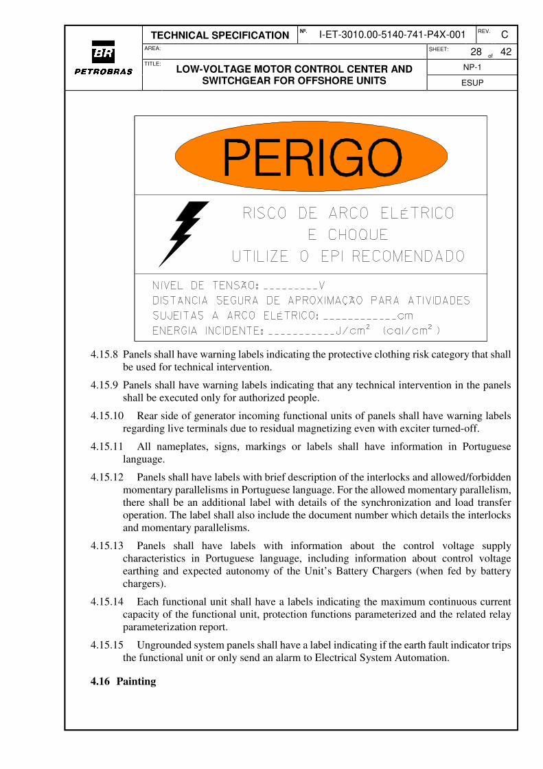
4.15.7.5 The Panels shall have warning labels following the model below, with the values of rated voltage (in field “Nível de Tensão”), arc fault incident energy (in field “Energia Incidente”) and arc-flash hazard distance (in field “Distância Segura de Aproximação para Atividades Sujeitas a Arco Elétrico”). The values to be filled in will be informed to Panel Manufacturer during Detailed Design.
TECHNICAL SPECIFICATION Nº.
I-ET-3010.00-5140-741-P4X-001 REV. C
AREA: SHEET: 28
of 42
TITLE:
LOW-VOLTAGE MOTOR CONTROL CENTER AND SWITCHGEAR FOR OFFSHORE UNITS
NP-1
ESUP
4.15.8 Panels shall have warning labels indicating the protective clothing risk category that shall be used for technical intervention.
4.15.9 Panels shall have warning labels indicating that any technical intervention in the panels shall be executed only for authorized people.
4.15.10 Rear side of generator incoming functional units of panels shall have warning labels regarding live terminals due to residual magnetizing even with exciter turned-off.
4.15.11 All nameplates, signs, markings or labels shall have information in Portuguese language.
4.15.12 Panels shall have labels with brief description of the interlocks and allowed/forbidden momentary parallelisms in Portuguese language. For the allowed momentary parallelism, there shall be an additional label with details of the synchronization and load transfer operation. The label shall also include the document number which details the interlocks and momentary parallelisms.
4.15.13 Panels shall have labels with information about the control voltage supply characteristics in Portuguese language, including information about control voltage earthing and expected autonomy of the Unit’s Battery Chargers (when fed by battery chargers).
4.15.14 Each functional unit shall have a labels indicating the maximum continuous current capacity of the functional unit, protection functions parameterized and the related relay parameterization report.
4.15.15 Ungrounded system panels shall have a label indicating if the earth fault indicator trips the functional unit or only send an alarm to Electrical System Automation.
4.16 Painting
TECHNICAL SPECIFICATION Nº.
I-ET-3010.00-5140-741-P4X-001 REV. C
AREA: SHEET: 29
of 42
TITLE:
LOW-VOLTAGE MOTOR CONTROL CENTER AND SWITCHGEAR FOR OFFSHORE UNITS
NP-1
ESUP
4.16.1 The painting process shall be proper for offshore installations and pre-qualified according to I-ET-3010.00-1200-956-P4X-001 - QUALIFICATION TESTS FOR PAINT SYSTEMS.
4.16.2 I-ET-3010.00-1200-956-P4X-001 - QUALIFICATION TESTS FOR PAINT SYSTEMSThe last coat colour shall be Light Green Munsell 5G8/4. Inner components mounting plates, internal faces of doors and safety barriers shall be Safety Orange Munsell 2.5YR6/14.
4.17 Protection
4.17.1 General Protection
4.17.1.1 For general protection, minimum protection functions for each functional unit and adjustments criteria, refer to I-ET-3010.00-5143-700-P4X-001 - ELECTRICAL SYSTEM PROTECTION CRITERIA.
4.17.1.2 In case any air circuit breaker is supplied with a built-in electronic trip unit (BETU), the BETU protection functions shall be disabled since the MMR protection functions shall have priority.
4.17.1.3 Each semi-bar of CDCs shall have one key activated selector switch in its front side, with the positions “Operação / Manutenção” (Operation / Maintenance). When this selector switch is in “Manutenção” position, the instantaneous overcurrent protection (function 50) of the relays of incoming and tie functional units shall be activated or their set points changed, overriding the protection coordination and minimizing damage in case of internal fault.
4.17.1.4 CDCs shall have one key activated selector switch in each MCC outgoing feeder front side, with the positions “Operação / Manutenção” (Operation / Maintenance). When this selector switch is in “Manutenção” position, the instantaneous overcurrent protection (function 50) of the relay of the respective outgoing feeder shall be activated or their set points changed, overriding the protection coordination and minimizing damage in case of internal fault.
4.17.1.5 CDC outgoing functional units for package panels without short-circuit withstand certification shall have one key activated selector switch in its front side, with the positions “Operação / Manutenção” (Operation / Maintenance). When this selector switch is in “Manutenção” position, the instantaneous overcurrent protection (function 50) of the relay of CDC outgoing functional unit shall be activated or their set points changed, overriding the protection coordination and minimizing damage in case of internal fault in package panel.
4.17.1.6 There shall be a local signalling lamp, turned on with the switch in “Manutenção” position, indicating “Coordenação Desativada”.
4.17.1.7 A network remote signalling of the position of the switch shall be sent to Electrical System Automation, from the respective incoming, tie circuit-breakers or outgoing MMRs.
4.17.1.8 For the cases described in 4.17.1.3, 4.17.1.4 and 4.19.1.4 there shall be a label beside the switch with following warning text:
TECHNICAL SPECIFICATION Nº.
I-ET-3010.00-5140-741-P4X-001 REV. C
AREA: SHEET: 30
of 42
TITLE:
LOW-VOLTAGE MOTOR CONTROL CENTER AND SWITCHGEAR FOR OFFSHORE UNITS
NP-1
ESUP
4.17.1.9 For the cases described in 4.17.1.3 and 4.17.1.5, there shall be a label beside the switch with following warning text:
4.17.2 Ground Fault Protection for High Impedance Grounded Systems
4.17.2.1 Ground fault protection shall be provided by 50GS function devices, installed in all outgoing circuits. Local alarm signalling shall be provided for each circuit.
4.17.2.2 Circuits for loads installed in hazardous areas Zone 1 and circuits for loads which cables cross hazardous areas Zone 1 shall be tripped by 50GS relay and one individual network alarm signal indicating trip by earth fault shall be sent by IR (MCC) or MMR (CDC) to A&C (Automation and Control System), through Electrical System Automation.
4.17.2.3 One network resume alarm signal (Low Insulation - Ground Fault) shall be sent to A&C, through Electrical System Automation, for each Panel, in case of failure in circuits that are not tripped. For CDCs, this signal shall be sent by incoming feeder MMR. For MCCs, this signal shall be sent by outgoing feeder MMR of upstream CDC.
4.17.3 Ground Fault Protection for Ungrounded Systems
4.17.3.1 Ground fault protection shall be provided by isolation monitoring devices (IMDs). Protective devices based in residual current shall not be accepted.
TECHNICAL SPECIFICATION Nº.
I-ET-3010.00-5140-741-P4X-001 REV. C
AREA: SHEET: 31
of 42
TITLE:
LOW-VOLTAGE MOTOR CONTROL CENTER AND SWITCHGEAR FOR OFFSHORE UNITS
NP-1
ESUP
4.17.3.2 One isolation monitoring device shall be installed in each busbar of CDC. These isolation monitoring devices shall be capable to operate with tie circuit-breaker of CDC in close or open position.
4.17.3.3 The isolation monitoring devices shall indicate the measured isolation resistance value between each phase and ground or between the three phases grouped and ground. The trip value shall be adjustable and the device shall be capable to detect simultaneous faults even in three different circuits.
4.17.3.4 The isolation monitoring device shall be capable to measure the isolation and to detect the ground fault in systems with cable total length (three phases) of one hundred kilometers (100km), without any failure or nuisance actuation.
4.17.3.5 All outgoing circuits of CDC shall have individual ground fault detector devices - EFI (Earth Fault Indicator). For loads installed in hazardous areas Zone 1 or which cables cross hazardous areas Zone 1, these devices shall instantaneously trip the circuit-breakers. A network alarm signal indicating trip by Earth Fault shall be sent by MMR to A&C, through Electrical System Automation. For loads that are not tripped, a network alarm signal indicating Earth Fault, shall be sent by MMR to A&C, through Electrical System Automation.
4.17.3.6 In MCCs, only outgoing circuits of loads installed in hazardous areas Zone 1 or which cables cross hazardous areas Zone 1 shall have individual ground fault detector devices (EFI) that shall instantaneously trip the circuit-breakers. A network alarm signal indicating trip by earth fault shall be sent by IR to A&C, through Electrical System Automation.
4.17.3.7 Other loads fed from MCCs shall be grouped per column in a same EFI. The fault finding in outgoing cables for these circuits in MCCs shall be through portable ground fault detector. These cables shall be installed in a way to enable easy access to clamp them with a portable ground fault detector, with the circuit energized. The shields shall be installed according to the detector requirements. A network alarm signal indicating earth fault shall be sent by each IR to A&C, through Electrical System Automation. Alternatively, this signal may be sent by an IR to A&C, through Electrical System Automation, located in the control cubicle of this panel.
4.17.3.8 Network alarm signal (Low Insulation - Ground Fault) shall be sent to A&C, through Electrical System Automation, for each Panel, in case of failure in circuits that are not tripped. For CDCs, this signal shall be sent by incoming MMR. For MCCs, the signal shall be sent by the outgoing functional unit that feeds the MCC.
4.17.3.9 When isolation monitoring device is disabled or turned off, a dedicated network alarm signal shall be sent to Electrical Automation System by the Incomers MMRs.
4.17.3.10 In Turbogenerators MCCs, ground fault detector devices (EFI) shall be compatible with the insulation monitoring devices installed in upstream switchgear.
4.17.3.11 Detailed design shall supply to Panel Manufacturer a list of all loads installed in hazardous areas.
4.17.3.12 MCCs shall be supplied with devices to indicate defective phase by means of three lamps connected between phases and ground through a NO (normally open) push-button. This system shall be compatible with insulation monitoring device installed in the CDC, in order to eliminate spurious alarms or trips.
TECHNICAL SPECIFICATION Nº.
I-ET-3010.00-5140-741-P4X-001 REV. C
AREA: SHEET: 32
of 42
TITLE:
LOW-VOLTAGE MOTOR CONTROL CENTER AND SWITCHGEAR FOR OFFSHORE UNITS
NP-1
ESUP
4.17.3.13 One portable ground fault detector shall be supplied with each purchased panel.
4.18 Electromagnetic Compatibility (EMC)
4.18.1 All equipment having electronic components or circuits shall comply with emission and immunity EMC (Electromagnetic Compatibility) and RFI (Radio Frequency Interference) requirements according to IEC 61000 and IEC 60533, presenting Performance Criterion A.
4.18.2 Regarding induced disturbances, all electronic equipment shall comply with IEC 61000-4-6 class 3.
4.18.3 Regarding surges, all electronic equipment shall comply with IEC 61000-4-5 class 4 with wave forms 1.2/50µs and 10/700µs and peaks up to 4kV.
4.18.4 Regarding oscillatory waves, all electronic equipment shall comply with IEC 61000-4-12 class 3 and common mode disturbances up to 150 kHz as per IEC 61000-4-16 level 4. Data communications and signal circuits shall be tested only in common mode, but at the same surge magnitude as specified for transverse mode tests, according to IEC 61850-3.
4.18.5 Regarding fast transients, all electronic equipment shall comply with IEC 61000-4-4 class 4, or above. In addition, power supply circuits shall be tested with transverse mode applied voltages, according to IEC 61850-3.
4.18.6 Regarding electromagnetic disturbances, all electronic equipment shall comply with IEC 61000-4-3 class 3.
4.18.7 Regarding damped oscillatory magnetic, all electronic equipment shall comply with IEC 61000-4-10 level 5.
4.18.8 Regarding power frequency magnetic field, all electronic equipment shall comply with IEC 61000-4-8 level 5 for continuous and short duration fields.
4.18.9 All electronic equipment shall operate correctly in the presence of a power frequency voltage in accordance with table 1 of IEC 61850-3
4.19 Control Voltages
4.19.1 MCCs
4.19.1.1 Control voltages for Turbogenerators low-voltage MCCs shall the same as for CDCs. Refer to item 4.19.2 for details.
4.19.1.2 For Turbogenerators low-voltage MCCs, decoupling modules, including blocking diodes, shall be foreseen to each control voltage source in order to avoid backfeeding control voltage sources. These decoupling modules shall monitor continuously the decoupling path. Failure in any component of the decoupling module shall generate a network alarm signal to A&C, through Electrical System Automation by Incomers IRs.
4.19.1.3 Outgoing functional units for Turbogenerators low-voltage MCCs shall be tripped by temporized undervoltage relay (ANSI Function 27) in order to avoid automatic restarting of turbogeneration auxiliary loads after a blackout event.
TECHNICAL SPECIFICATION Nº.
I-ET-3010.00-5140-741-P4X-001 REV. C
AREA: SHEET: 33
of 42
TITLE:
LOW-VOLTAGE MOTOR CONTROL CENTER AND SWITCHGEAR FOR OFFSHORE UNITS
NP-1
ESUP
4.19.1.4 Except for Turbogenerators low-voltage MCCs, the control voltage for each MCC shall be supplied by two withdrawable auxiliary transformers 480-120VAC, each one connected to one busbar end. Each auxiliary transformer shall be dimensioned to 125% of the MCC control circuits’ total power.
4.19.1.5 The primary winding of the auxiliary transformers in MCCs shall be protected by circuit-breakers. The secondary winding and each control circuit branch shall be suitably protected with miniature circuit-breakers.
4.19.1.6 The control busbar shall be split in two semi-bars, each one provided with a rotary selector switch of at least 20A for selection of the auxiliary transformer.
4.19.1.7 If it is necessary the addition of 24VDC sources to feed the IRs, the same criteria shall be adopted and two switched power supply, each one with capacity for supply the entire control system shall be installed. Blocking diodes shall be added to the output of each DC source.
4.19.1.8 The secondary winding of the auxiliary transformers shall have one terminal bolted grounded.
4.19.1.9 Undervoltage at any 120Vac or 220 VDC control semi-bars shall generate a network alarm signal (Control Voltage Failure) to A&C through Electrical System Automation by redundant IRs, each one fed from one control voltage source, both located at control section of the MCC. Each IR shall detect Control Voltage Failure from both semi-bars simultaneously. These IRs may be used to group general MCC discrete signals (not from specific functional units) and send to Electrical System Automation through network.
4.19.1.10 Outgoing Functional Units for motors located in MCCs with protective devices supplied together with the motor as, for example, bearing over temperature protection shall supply 220 VDC to the protective device by using a dedicated circuit breaker installed in the functional unit. Protective devices supplied together with motors which are fed by MCCs with control voltage of 120 VAC shall be fed by 220 VDC independently from the MCC.
4.19.2 CDCs
4.19.2.1 The control voltage for each Panel shall be in 220VDC achieved from Unit’s redundant battery-chargers.
4.19.2.2 The Panels shall have two control busbars, one for loads connected to main busbar A and other for loads connected to main busbar B.
4.19.2.3 Each control busbar shall be fed by both control voltage sources (redundant battery chargers) continuously in parallel.
4.19.2.4 CDCs connected to Emergency and Auxiliary Generators shall have a third option for control voltage supply, by means of an auxiliary rectifier with incoming rated voltage in 480VAC and outgoing rated voltage in 220VDC, connected to the terminals of incoming feeders of Emergency or Auxiliary Generator. The auxiliary rectifier shall be installed in the CDC (included in CDC Manufacturer scope of supply) and shall have the proper capacity to supply control loads of the CDC. In these cases, there shall be a switch in order to select the control voltage source from the Emergency or Auxiliary Generator or from the main control voltage sources (Unit’s redundant battery chargers).
TECHNICAL SPECIFICATION Nº.
I-ET-3010.00-5140-741-P4X-001 REV. C
AREA: SHEET: 34
of 42
TITLE:
LOW-VOLTAGE MOTOR CONTROL CENTER AND SWITCHGEAR FOR OFFSHORE UNITS
NP-1
ESUP
4.19.2.5 Decoupling modules, including blocking diodes, shall be foreseen to each control voltage source in order to avoid backfeeding control voltage sources. These decoupling modules shall monitor continuously the decoupling path. Failure in any component of the decoupling module shall generate a network alarm signal to A&C, through Electrical System Automation by Incomers MMRs.
4.19.2.6 Control incoming circuits from the external power supply shall have surge protective devices (SPD) with a maximum discharge current of 10 kA in 8/20 microseconds, as required by NFPA 780.
4.19.2.7 Each control busbar incoming shall be protected by miniature circuit- breakers. The busbars shall be connected by a normally open tie circuit-breaker.
4.19.2.8 Undervoltage at any 220 VDC control voltage sources at the panel shall generate a remote network alarm signal (control voltage failure) to A&C, through Electrical System Automation by Incomers MMRs. Each Incomer MMR shall detect control voltage failure from both control voltage sources redundantly.
4.19.2.9 Functional Units shall not be tripped for lack of control voltage in MMRs.
4.19.2.10 Outgoing Functional Units for motors located in CDCs with protective devices supplied together with the motor as, for example, bearing over temperature protection shall supply 220 VDC to the protective device by using a dedicated circuit breaker installed in the functional unit.
4.20 Auxiliary Voltages
4.20.1 The power supply for heating resistors shall be achieved from 220VAC three phase external source. The circuits for heating resistors shall be two phases and shall be balanced among three phases internally.
4.20.2 Each panel division for transport shall be provided with externally accessible terminals to energize the heating circuits during storage periods. These terminals shall have a label with:
4.20.3 The power supply for internal lighting and sockets outlets shall be achieved from the same 220VAC three phase external source that feeds the heating resistors. The circuits for internal lighting and sockets outlets shall be two phases and shall be balanced among three phases internally.
4.20.4 The auxiliary circuit branches for internal lighting and internal sockets shall have miniature thermomagnetic circuit-breakers with integrated or additional differential residual current protection.
4.21 Interface with Automation
4.21.1 Panel Manufacturer shall propose the internal network architecture among IEDs, complying with requirements of I-ET-3010.00-5140-797-P4X-001 - ELECTRICAL
TECHNICAL SPECIFICATION Nº.
I-ET-3010.00-5140-741-P4X-001 REV. C
AREA: SHEET: 35
of 42
TITLE:
LOW-VOLTAGE MOTOR CONTROL CENTER AND SWITCHGEAR FOR OFFSHORE UNITS
NP-1
ESUP
SYSTEM AUTOMATION ARCHITECTURE. This internal network architecture and configuration shall be submitted to PETROBRAS approval.
4.21.2 Devices connected to the networks shall have the time synchronized with Electrical System Automation Time Servers actual time. Refer to I-ET-3010.00-5140-797-P4X-001 - ELECTRICAL SYSTEM AUTOMATION ARCHITECTURE and I-DE-3010.00-5140-797-P4X-001 - ELECTRICAL SYSTEM AUTOMATION ARCHITECTURE DIAGRAM.
4.21.3 Minimum Interface Signals to be exchanged are listed in I-LI-3010.00-5140-797-P4X-001 - ELECTRICAL SYSTEM AUTOMATION INTERFACE SIGNALS LIST.
4.21.4 Switches internal to the panel shall be manageable.
5. MANUFACTURER DOCUMENTATION
5.1 The following documents shall be provided by Panel Manufacturer, at proposal:
a) Documents list;
b) Dimensional drawings including frontal and upper views, estimated weight and thermal dissipation;
c) Technical catalogues with information about all components;
d) Spare parts list for two years of operation, including item, part number, quantity, description, MTBF and prices for each part;
e) Technical assistance prices and representative address;
f) Panel Data-sheet issued by PETROBRAS completely filled in with Manufacturer data with identification of the person responsible for the filling. This Data-sheet shall be submitted to PETROBRAS approval.
g) Data Sheet following template defined in I-LI-3010.00-5140-700-P4X-001 - ELECTRICAL EQUIPMENT DATA-SHEET MODELS, when not issued by PETROBRAS, completely filled in, with identification of the person responsible for the filling. This Data-Sheet shall be submitted to PETROBRAS approval;
h) List of applicable standards;
i) Inspection and test schedule, including acceptance criteria for each test;
j) Type tests certificates;
k) Certificate for testing under conditions of arcing due to internal fault for CDCs;
l) Dimensional drawing for connections to bus trunking, when applicable;
m) Time-current curves, current peak limiting curves and i²t minimum and total values of the limiting fuses;
n) One-line electrical drawings;
o) Other documents required in project documentation.
5.2 The following documents shall be provided by Panel Manufacturer, for approval:
a) Documents list;
TECHNICAL SPECIFICATION Nº.
I-ET-3010.00-5140-741-P4X-001 REV. C
AREA: SHEET: 36
of 42
TITLE:
LOW-VOLTAGE MOTOR CONTROL CENTER AND SWITCHGEAR FOR OFFSHORE UNITS
NP-1
ESUP
b) Dimensional drawings including frontal and upper views, details, location of lifting eyelets, area for incoming cables and fixing base details;
c) Weight and volume for each unit for transportation;
d) Total weight;
e) Thermal dissipation at half load and full load, of portion of panel thermal dissipation that is independent of electrical system loading and the components responsible for this dissipation;
f) Dimensional drawing for connections to bus trunking, when applicable;
g) Electrical drawings, including one-line, three-lines and functional diagrams;
h) Connection diagrams, including all terminal blocks;
i) Electrical Functional Units Classification List according to control mode; j) Saturation curves of current transformers;
k) Components and material list per functional unit;
l) Time-current curves, current peak limiting curves and i²t minimum and total values of the limiting fuses;
m) Package and transportation instructions;
n) Warranty certificate and declaration of availability of spare parts for 10 (ten) years;
o) Extraction and insertion instructions;
p) Network architecture internal to the Panel;
q) Network configuration, parameterization, screens, and monitoring documentation for all equipment that will be connected by network;
r) Memory map;
s) Communication List, including IP list and I/O for each Functional Unit;
t) Expected MTTR for each type of functional unit and for each component;
u) Type tests certifications.
v) Relays parameterization report.
5.3 The following documents shall be provided by Panel Manufacturer, with the Panel:
a) Data-sheet full-filed "as built";
b) Storage, lifting and unpacking instructions in Portuguese language;
c) Installation and assembly instructions in Portuguese language;
d) Operation instructions in Portuguese language, according to I-ET-3010.00-0000-91A-P4X-001 - TECHNICAL DOCUMENTATION REQUIREMENTS;
e) Maintenance instructions, including list of necessary equipment, accessories and tools in Portuguese language, according to I-ET-3010.00-0000-91A-P4X-001 - TECHNICAL DOCUMENTATION REQUIREMENTS;
f) Spare parts lists;
g) "As built" technical catalogue for all components;
TECHNICAL SPECIFICATION Nº.
I-ET-3010.00-5140-741-P4X-001 REV. C
AREA: SHEET: 37
of 42
TITLE:
LOW-VOLTAGE MOTOR CONTROL CENTER AND SWITCHGEAR FOR OFFSHORE UNITS
NP-1
ESUP
h) Complete test report, including type, routine and special tests;
i) Complete version of configuration, parameterisation and monitoring softwares for switches, concentrators, gateway devices, IRs, MMR, VSDs and any other equipment that could be configured or monitored by software. These softwares shall provide facilities for full diagnosis of respective devices;
j) Complete manuals for installation and configuration of all softwares in Portuguese language;
k) Components list, including at least, item, description, draw, unit, quantity and part number.
l) Constructive details about baseplate fixation screws, such as quantity, size, type and position in baseplate.
6. PACKAGE AND TRANSPORT
6.1 Panels shall be packed properly for the foreseen transportation, so that no damage occurs during transport, storage and lifting operations;
6.2 Each volume shall be properly identified with:
a) Storage position;
b) PETROBRAS unit, achievement, and business unit;
c) Delivery address
d) Material Requisition number;
e) Panel TAG;
f) Manufacturer name and address;
g) Weight;
h) Contract number.
7. INSPECTION AND TESTS
7.1 General
7.1.1 The Manufacturer or an independent inspection authority accepted by PETROBRAS shall perform all inspections and tests, in conformity with the specification documents and applicable rules.
7.1.2 Manufacturer shall be responsible for obtaining all necessary certification related to the equipment.
7.1.3 Manufacturer shall be responsible for contacting the Classification Society, in order to define the procedures to be followed, related to the submission of documents, and to carry out the necessary inspections and tests to certificate the Panels.
7.2 Design Verification
7.2.1 Design verification shall follow the requirements of IEC 61439-1, IEC61439-2, IEC 60092-302 and IEC 61892-3. According to IEC61439-1, the methods that check design
TECHNICAL SPECIFICATION Nº.
I-ET-3010.00-5140-741-P4X-001 REV. C
AREA: SHEET: 38
of 42
TITLE:
LOW-VOLTAGE MOTOR CONTROL CENTER AND SWITCHGEAR FOR OFFSHORE UNITS
NP-1
ESUP
verification are testing, comparison with a tested reference design or assessment (confirmation of the correct application of calculations and design rules, including use of appropriate safety margins). Design verification and methods are summarised in Table 1, where they are identified as “D”.
7.2.2 Certified test reports for design verification tests performed for identical panels or a panel tested reference design (when applicable, according to IEC 61439-1) and approved and witnessed by Classification Society are accepted. These reports shall be included al proposal by manufacturer.
7.3 Routine Verification
7.3.1 Routine tests shall follow the requirements of IEC 61439-1, IEC 61439-2, IEC 60092-302 and IEC 61892-3. They are summarised in Table 1, where they are identified as “R”.
7.3.2 Routine tests shall be carried out for all Panels.
7.4 Special Tests
7.4.1 Special tests shall be carried out according to Table 1, where they are identified as “S”.
Table 1 – Minimum Tests Required
Test D R S Method and Acceptance
Criteria
Examination of technical documentation (1) x x x Verification of certificate of accuracy for measurement instruments to be used in tests (1) x x x
Dimensional verification (2) x Panel Data-sheet Visual inspection, verification of data on nameplates and labels and Marking Tests
x IEC 61439-1 and this ET
Painting (colour, thickness and adhesion) x
I-ET-3010.00-1200-956-
P4X-001 - QUALIFICATION
TESTS FOR PAINT SYSTEMS and this ET
Verification by testing of the resistance to corrosion x Severity Test B - IEC61439-1
Verification by testing of thermal stability of enclosures x IEC 61439-1 Verification by testing of resistance of insulating materials to abnormal heat and fire due to internal electric effects x IEC 61439-1
Verification by assessment of resistance to ultra-violet (UV) radiation
x IEC 61439-1
Lifting test x IEC 61439-1 Verification by assessment of incorporation of switching devices and components
x IEC 61439-1
Verification by comparison of a reference design or by testing of temperature rise limits (2)
x IEC 61892-3 and IEC
61439-1
Verification by testing of dielectric properties (2) x IEC 61439-1, IEC 61439-
2 and IEC 61180
TECHNICAL SPECIFICATION Nº.
I-ET-3010.00-5140-741-P4X-001 REV. C
AREA: SHEET: 39
of 42
TITLE:
LOW-VOLTAGE MOTOR CONTROL CENTER AND SWITCHGEAR FOR OFFSHORE UNITS
NP-1
ESUP
Test D R S Method and Acceptance
Criteria
Verification by testing of short-circuit withstand strength (7) x IEC 61439-1 Verification by testing of protection against electric shock and integrity of protective circuits
x x IEC 61439-1
Verification by testing of clearance and creepage distances x x IEC 61439-1
Verification by testing of mechanical operation x x IEC 61439-1 and IEC
61439-2 Verification by assessment of degree of protection of enclosure (IP)
x x IEC 61439-1, IEC 61439-
2 and IEC 60529 Wiring, operational performance and function x IEC 61439-1
Mechanical impacts tests x IEC 61439-1 and IEC
62262 Verification by assessment of internal electrical circuits and connections
x x IEC 61439-1
Verification by assessment of terminals for external conductors
x x IEC 61439-1
Inspection of assembly, inspection of wiring and electrical operation test
x IEC 61439-1
EMC – Conducted emission test (3) x IEC 60533 EMC – Radiated emission test (3) x IEC 60533 EMC – Conducted low frequency interference (3) x IEC 60533 EMC – Power supply variation (3) x IEC 60533 EMC – Power supply failure (3) x IEC 60533 EMC – Surge voltage test (3) x IEC 60533 EMC – Electrical fast transient test (3) x IEC 60533 EMC – Electromagnetic field test (3) x IEC 60533 EMC – Electrostatic discharges (ESD) (3) x IEC 60533 EMC – Conducted radio frequency interference test (3) x IEC 60533 Measurement of impedance at rated continuous current for current limiting reactors
x IEC 60076-6
Measurement of loss for current limiting reactors x IEC 60076-6 Winding overvoltage test for current limiting reactors x IEC 60076-6 Temperature rise test at rated current for current limiting reactors
x IEC 60076-6
Short-circuit current test for current limiting reactors, with rated mechanical short-circuit current
x IEC 60076-6
Short-circuit current test for current limiting reactors, with rated thermal short-circuit current and rated thermal short-circuit duration
x IEC 60076-6
Measurement of acoustic sound level at rated continuous current for current limiting reactors
x IEC 60076-6
Measurement of coupling factor for current limiting reactors x IEC 60076-6 Measurement of Ohmic resistance, reactive inductance and losses at rated current and frequency for limiting reactor
x Panel Data-sheet
Condition of Arcing due to internal fault for CDCs x All assessment criteria of
IEC TR 61641
TECHNICAL SPECIFICATION Nº.
I-ET-3010.00-5140-741-P4X-001 REV. C
AREA: SHEET: 40
of 42
TITLE:
LOW-VOLTAGE MOTOR CONTROL CENTER AND SWITCHGEAR FOR OFFSHORE UNITS
NP-1
ESUP
Test D R S Method and Acceptance
Criteria
Complete functional tests (including interlocks) (5) x Project documents and
IEC 61850 Verification of measuring instruments x Project documents
Verification of relays parametrization and operation (6) x Selectivity study and IEC
61850 Verification of signalling devices x Project documents Verification of heating resistors operation x This ET and Data-sheet Test of interchangeability of drawers x This ET Temperature rise for circuit-breakers x IEC 60947-2 Tripping limits and characteristics for circuit-breakers x IEC 60947-2 Dielectric for circuit-breakers x IEC 60947-2 Operation performance capability for circuit-breakers x IEC 60947-2 Overload performance for circuit-breakers, where applicable x IEC 60947-2 Short-circuit breaking capability for circuit-breakers x IEC 60947-2 Short-time withstand current for circuit-breakers, where applicable
x IEC 60947-2
Notes: 1. For all witnessed tests;
2. For MCCs, this test includes the current limiting reactors, installed in the enclosure;
3. EMC tests shall be carried out when required in IEC 60533 for the equipment installed in the Panel;
4. Manufacturer shall be present at site, after the panel assembly and transport, to verify, together with PETROBRAS, if the Panel is at the same conditions as it was when factory delivered it and to verify if the Panel is ready to start operation;
5. These tests shall include all tests related to network communication among devices (alarms, interlocks, GOOSE, etc.). For IEC 61850 networks, these tests shall use calibration boxes certified for IEC 61850;
6. These tests shall include check of A/D converters of relays. For relays specified for IEC 61850 protocol, these tests shall use calibration boxes certified for IEC 61850.
7. Design verification by comparison with a reference design for short-circuit withstand strength of the protective circuit can be submitted for PETROBRAS analysis andr approval.
8. TRAINING
8.1 Manufacturer shall provide training for at least 10 (ten) PETROBRAS personnel, about Panels system and components.
8.2 Training shall be provided in Brazil, during commissioning period, in Portuguese language.
8.3 Training plan shall include at least control diagram analysis, storage, transportation, installation, operation, corrective maintenance, preventive maintenance, disassembly, assembly, extraction and insertion of drawers, use of tools and accessories, interface with automation, use of softwares, configuration, parameterization and adjustment of IEDs, equipment and devices.
TECHNICAL SPECIFICATION Nº.
I-ET-3010.00-5140-741-P4X-001 REV. C
AREA: SHEET: 41
of 42
TITLE:
LOW-VOLTAGE MOTOR CONTROL CENTER AND SWITCHGEAR FOR OFFSHORE UNITS
NP-1
ESUP
9. SPARE PARTS AND TOOLS
9.1 Manufacturer shall provide the necessary spare parts for the commissioning and pre operation periods;
9.2 Manufacturer shall provide a list of spare parts for all electrical equipment, for at least 2 (two) years of continuous operation, including prices and part number codes.
9.3 Manufacturer shall provide all unusual tools necessary for maintenance, assembly or disassembly of the Panel.
10. DATA SHEETS FORMS
For data-Sheet models for low-voltage MCCs and switchgears, refer to I-LI-3010.00-5140-700-P4X-001 - ELECTRICAL EQUIPMENT DATA-SHEET MODELS.
11. ABBREVIATIONS AND ACRONYMS
ABBREVIATIONS AND ACRONYMS
A&C Automation and Control System
AISI American Iron and Steel Institute
BETU Built-in Electronic Trip Unit (a type of IED)
CDC Switchgear
CT Current Transformer
EA01 to EA04
Electric Actuation Type 01 to Electric Actuation Type 04
EFI Earth Fault Indicator
EMC Electromagnetic Compatibility
EPR Ethylene Propylene Rubber
ESD Emergency Shut-Down
ET Technical Specification
FPSO Floating, Production, Storage and Offloading Unit
FSO Floating, Storage and Offloading Unit
Icw Rated Short-Time Withstand Current (as defined in IEC 61439-1)
IEC International Electrotechnical Commission
IED Intelligent Electronic Device (as defined in IEC 61850)
IEEE Institute of Electrical and Electronics Engineers
IMD Isolation Monitoring Device
In Rated Current (as defined in IEC 61439-1)
ip Peak Short-Circuit Current (as defined in IEC 60909)
Ip arc Permissible Current under Arcing Conditions (as defined in IEC TR 61641)
Ipk Rated Withstand Peak Current (as defined in IEC 61439-1)
IR Intelligent Relay
Ith Thermal Equivalent Short-Circuit Current (as defined in IEC 60909)
MCC Motor Control Center
MMR Microprocessor-Based Multifunction Relay (a type of IED)
MTBF Mean Time Between Failures
TECHNICAL SPECIFICATION Nº.
I-ET-3010.00-5140-741-P4X-001 REV. C
AREA: SHEET: 42
of 42
TITLE:
LOW-VOLTAGE MOTOR CONTROL CENTER AND SWITCHGEAR FOR OFFSHORE UNITS
NP-1
ESUP
ABBREVIATIONS AND ACRONYMS
MTTR Mean Time to Repair
PVC Polyvinyl Chloride
r.m.s Root Mean Square
RM Material Requisition
R Routine Test
S Special Test
tarc Permissible Arc Duration (as defined in IEC TR 61641)
THD Total Harmonic Distortion
T Type Test
U Rated Power Frequency Voltage Between Conductors for which the Cable is Designed
U0 Rated Voltage Between Conductor and Earth or Metallic Screen for which Cable is Designed