TECHNICAL SPECIFICATION OF LATCH BALL SCREWS 1.0 SCOPE: This specification establishes the requirement for procurement of raw material, manufacture and inspection of components, assembly, shop testing, running-in, cleaning, packing and shipment of ball screw assemblies for requirements as detailed below: 2.0 CONTENTS The provisions of this specification are presented under the following section headings” Section Applicable specification and drawing 3 Requirement of ball screw assemblies 4 Manufacturing requirements 5 Inspection and Performance testing 6 Certification required 7 Requirement after placement of order 8 Packing and shipping 9 Quality Surveillance 10 Shipping release 11 3.0 APPLICABLE SPECIFICATINS AND DRAWINGS: Latest issues of the standards listed below, in effect of the time of manufacture, constitute a part of this specification to the extent specified herein. In the event that certain provisions of the standards listed below conflict with the requirements of these specifications, the requirement of this specification shall govern. 3.1 STANDARDS AND SPECIFICATIONS ASTM – A 564 Specification for precipitation hardening alloy bars, forgings and forging stocks for high temperature service. ASTM –A 370 Standard methods and definitions for testing of steel products. ASTM – E 18 Standard methods for tests for Rockwell hardness and Rockwell superficial hardness of metallic materials. ASTM – E 138 Specification for wet magnetic particle testing. ASTM – A 388 Recommended practice for Ultrasonic testing and inspection of Heavy forgings.
Transcript
TECHNICAL SPECIFICATION OF LATCH BALL SCREWS 1.0 SCOPE:
This specification establishes the requirement for procurement of raw material, manufacture and inspection of components, assembly, shop testing, running-in, cleaning, packing and shipment of ball screw assemblies for requirements as detailed below:
2.0 CONTENTS The provisions of this specification are presented under the following section headings”
Section
Applicable specification and drawing 3
Requirement of ball screw assemblies 4
Manufacturing requirements 5
Inspection and Performance testing 6
Certification required 7
Requirement after placement of order 8
Packing and shipping 9
Quality Surveillance 10
Shipping release 11
3.0 APPLICABLE SPECIFICATINS AND DRAWINGS:
Latest issues of the standards listed below, in effect of the time of manufacture, constitute a part of this specification to the extent specified herein. In the event that certain provisions of the standards listed below conflict with the requirements of these specifications, the requirement of this specification shall govern.
3.1 STANDARDS AND SPECIFICATIONS
ASTM – A 564 Specification for precipitation hardening alloy bars, forgings and
forging stocks for high temperature service.
ASTM –A 370 Standard methods and definitions for testing of steel products.
ASTM – E 18 Standard methods for tests for Rockwell hardness and Rockwell superficial hardness of metallic materials.
ASTM – E 138 Specification for wet magnetic particle testing.
ASTM – A 388 Recommended practice for Ultrasonic testing and inspection of Heavy forgings.
ASTM – E165 Specification for Dye Penetrant Testing (DPT is for materials not
covered under MPI).
PP – E – 438 Specifications for Hard Chrome plating (will be provided after placing PO, if required).
3.2 DRAWINGS AND PROCEDURES: 3.2.1 Ball Screw Assembly Manufacturer drawings as listed shall be used for fabrication. Designation Drawing No.
4.0 REQUIREMENT OF BALL SCREW ASSEMBLIES: 4.1 Overall sizes:
Features and overall sizes of the ball screw assemblies shall be as per drawings listed in section 3.2 above.
4.2 Materials of construction:
All materials used to manufacture the components and other parts forming part of the ball screw assemblies shall be corrosion resistant and be suitable for water services. Materials of construction of ball screw assemblies shall be as follows:
Ball nuts for type FM-L (RM), Ball return tubes and screw shaft of types FM-L (RM) ball screw assemblies
Precipitation hardening stainless steel to ASTM: A564 Gr. 630 vacuum degassed and electro slag refined. Precipitation hardened to condition H925 achieving hardness RC 38 min.
Balls Satellite 19PM, Hardness RC 46 – 51. NOTE: M/s. Hoover precision satellite 19 PM balls with 1.5% to 2.4% carbon content and a surface finish of Ra 0.05 micron, for Ram B and latch ball screw & nut assemblies is acceptable in place of Stellite 19 PM balls.
4.3 Supplier shall carry out detailed to meet the dimensional and other requirements specified on
the drawings mentioned above and in this specification. The Ball screw assemblies are to be manufactured as per the following requirements.
4.3.1 Ball Tracks Ball tracks in ball screw shafts and ball nuts shall be precision ground and shall be of Gothic arch profile with conformity of 52% - 53%. Ball tracks shall be right hand single start threads.
4.3.2 Balls
Balls used in all Ball screw assemblies shall be precision ground and shall confirm to AFBMA Gr. 25 or better. Three axis X-Ray shall be carried out on all balls. Balls shall be free from any defects. In addition to above balls in assembly, spare balls of 150 nos. per each assembly shall be supplied.
4.3.3 Special screws 30 Nos. of latch ball nut ball pickup tube mounting special screws with original washers per each assembly shall be supplied.
4.3.4. Water Lubricated Ball bearings: Latch Ball Screw shall be supplied along with Water Lubricated Ball bearing set as per specifications and drawing 35221/2083/DD attached. In addition above set, one spare set of water lubricated ball bearing per each assembly shall be supplied. One set consists of three bearings.
4.4 Design parameters and operating conditions of ball screw assemblies are show in the following Table-1. TABLE – 1 Sl. No. Description Type FM-L (RM) 1. Screw Rotates 2. Nut Travels Linearly 3. Attitude in which the ball screw assemblies operate. Horizontal 4. Medium in which ball screw assemblies operate. Water
PH 9.5 to 10.5 5. Temperature of Medium Deg. C Normal 120
Maximum – 175 6. Pressure of medium Kg/Sq. Cm 110 7. Dia of screw shaft in mm. 44 8. Total length of screw shaft (mm) 375 9. Length of nut in mm 238 10. Dia of balls in mm 3.962 11. Pitch, mm right hand single start 6.350 12. Radial backlash in mm 0.030/0.060 13. Pitch Error 0.010mm in 200mm 14. Conformity of ball track profile. 52% to 53% of Gothic
16.2 Operating speed – low - (One speed only) 17. Rate of travel (max.) 1895 mm / min (nut) 17.1 Operating speed – high 625 mm / min (nut) 17.2 Operating speed – low - 18. Maximum axial load in operation in both directions. 825 Kgf. (Tensile and
Compressive) 19. Maximum thrust load when stalled in ‘Kgf’ with screw
shaft fully extended. 825 Kgf. (Compressive)
20. Service life required 26 x 10^6 mm of travel cumulative of backward and forward strokes.
21. Pre-load on nut for torque measurement and running 458 Kgf. 22. Maximum torque for 17 above 40 Kgf-cm (includes
supporting bearings frictional torque)
23. Type of ball recirculation External 24. Number of balls - 24.1 Number of balls in each ball circuit 75 24.2 Total number of balls in assembly 150
5.0 MANUFACTURING REQUIREMENTS: 5.1 General
Components of the Ball Screw Assemblies shall be manufactured with best possible workmanship to ensure trouble free operation and satisfactory service life.
5.2 Cleanliness:
Good clean conditions shall be maintained during all stages manufacturing, assembly and shop testing of ball screw assemblies. Assembly and testing shall be done in a dust free controlled atmosphere room.
5.3 Raw material for manufacture of components:
Raw materials for manufacturing the components of ball screw assemblies shall be complied as per 4.2 above and our drawings listed in 3.2 above. Material conforming to ASTM A564 shall be procured in solution-annealed condition. Prior to precipitation hardening to conditions H900, H925 etc., the raw material stock shall be rough machined with a finish machining allowance of 3mm or less. Precipitation hardening shall be done as per 5.5.1 below:
5.4 Raw material identification:
All materials used for manufacture of components of ball screw assemblies and designed with ASTM or BS or DIN standards shall be tested as required by such standards and this specification. Proof in the form of certified test reports or mill test certificates that the required tests have been carried out at source will be acceptable. If original mill test certificates are not available & not co-relatable with material, the supplier shall perform the tests. Copies of all materials test certificates shall be furnished to the Purchaser.
5.5 Heat Treatment
5.5.1 Precipitation Hardening Heat Treatment
Precipitation hardening shall be carried out as per the following procedures:
H925 Condition Heat to 5000 C + 50 C, hold at this temperature for 4 hours +/-15minutes and air-cool to room temperature.
H900 Heat to 4820 C + 50 C, hold at this temperature for 4 hours +/-5minutes and air-cool to room temperature.
5.5.2 Heat Treatment procedures for precipitation Hardening:
All heat treatment operations shall be carried out to established procedures so as to achieve the desired physical properties. Copies of these procedures shall be furnished to the purchaser for his comments before commencing hear treatment.
5.5.3 Heat Treatment Equipment:
Precipitation hardening heat treatment shall be carried out in electrically heated forced air circulation furnaces that have been checked for temperature uniformity. Thermocouples, temperature controllers and temperature recorders shall be calibrated as a whole for accuracy of indication of job temperature within + 50 C. Temperature uniformity of the working zone of the furnace shall be within + 50 C at the difference holding temperatures.
5.5.4 Heat Treatment Records: Time-temperature charts shall be maintained for all heat treatment operations and shall be
kept identified with the components that have been heat-treated. Copies of time temperature charts for all heat treatment operations shall be furnished to the purchaser for his records.
5.5.5 Witness pieces during Heat Treatment: At least one 250mm long witness piece per heat treatment batch and per raw material heat
shall be used along with the materials being heat treated. These witness pieces shall be of appropriate size and be representative of material being precipitation hardened. From each witness pieces, three standard 12.00mm dia., tensile test specimen and three Charpy V-notch impact test specimen as per ASTM A370 and a circular slice, 25mm thick, for checking hardness shall be machined. If the diameter of the witness piece does not permit machining of 3 tensile and impact test specimens, adequate length of witness piece shall be used for machining 3 tensile, 1 hardness test and 3 impact test specimens per heat treatment batch and per raw material heat.
5.5.6 Stress Relief:
If necessary, the screw can be straightening in the cold condition followed by stress relieving at 5000 C. max., for about 2 hours. Procedure for stress relief shall be forwarded for our approval.
5.6 Properties to be achieved after precipitation hardening:
After precipitation hardening het treatment, three (3) standard 12mm dia., tensile test specimens, 3 Charpy V-notch impact test specimens 10mm x 10mm and a 25mm thick slice shall be machined from the witness piece / witness pieces. The tensile and impact test specimens shall be as per ASTM: A370 and these shall be tested in qualified testing machines. Hardness shall be checked across two perpendicular diameters of the 25mm thick slice. Properties obtained for the different precipitation hardening heat treatments shall be as follows:
Condition H925 UTS (min) in Kg/sq. Mm 120 Y.S. (mm) at 0.2% strain in Kg/sq.mm 110 % Elongation (min) 10 % Reduction in area (min) 38 Hardness Range RC 38 – 45 Impact absorbed energy value 0.7 Kg-m
5.7 Cleaning and passivation: After finish machining and inspection but prior to assembly all components shall be
thoroughly cleaned with acetone to remove all traces of cutting oil, other contaminations etc.
6.0 INSPECTION AND PERFORMANCE TESTING: Supplier shall be responsible for and shall provide for and perform all inspection and testing specified in this specification. Inspection and testing shall be conducted to a manner satisfactory to and shall be subject to approval by the Purchaser.
6.1 Inspection 6.1.1 Ultrasonic Examination of Raw materials:
After heat treatment, the entire length of each screw shaft bar, ball nut forging and other raw material shall be ultrasonically examined by straight beam and angle beam methods, by qualified personnel in accordance with ASTM: A 388 (Recommended practice for Ultrasonic Testing and Inspection of Heavy Forgings). Supplier shall furnish a procedure for ultrasonic examination proposed to be carried out by him. The procedure shall be subject to approval by the Purchaser. A screw shaft bar or ball nut forging shall be unacceptable: a) If ultrasonic examination results show one or more reflections, which produce
indications, accompanied by total loss of back reflection, not associated with attributable to the geometric configuration. Complete loss in back reflection is assumed when the back reflection falls below 5% of full calibration amplitude.
b) If presence of crack is indicated in the material. c) If ultrasonic examination reveals indications greater than those indicated by a 1.2 mm
(3/64”) diameter flat bottom hole with 12mm (1/2”) deep. 6.1.2 Fluorescent wet Magnetic particle Inspection:
All finish ground surfaces of screw shaft, ball nut etc., shall be inspected by fluorescent wet magnetic particle method as per ASTM: E138. Supplier shall furnish a procedure for fluorescent wet magnetic particle inspection proposed to be carried out by him. The procedure shall indicate all relevant details such as surface preparation, details of machine used, its voltage and current rating, sequence of operation, details of machine used, its voltage and current rating, sequence of operation, details of machine used, its voltage and current rating, sequence of operation, specification of particles used etc. The procedure shall be subject to approval of purchaser. The following relevant indications are unacceptable:- Crack or linear indication. Rounded indications with dimensions greater than 1.5mm. Four or more rounded indications in a line separated by 1.5mm or less edge to edge. Ten or more rounded indications in any 40 square cm., of surface area with major
dimensions of this area taken in the most unfavourable location relative to the indications being evaluated.
Any indication that is believed to be non-relevant shall be regarded as defect until it is re-examined to verify whether actual defects are present.
6.1.3 Inspection of satellite balls:
Stellite-19 PM balls shall be inspected by 3-axis X-Ray method for crack detection as per ASTM E-94 & E-142.
6.1.4 Dimensional Inspection:
Supplier shall carry out 100% dimensional inspection of all components and furnish these dimensional inspection reports to be Purchaser. Such inspection shall include the following indicated on Purchaser’s drawings and drawings prepared and furnished by the supplier and approved by the Purchaser. All dimensional details including concentricity, squareness, run out, straightness etc.
of components of ball screw assemblies. Surface finish, where specified. Thread sizes-with ring or plug gauges. Gothic arch profile conformity – for checking this procedure shall be furnished by
the supplier. Dimensional inspection of the balls to confirm the AFBMA grading.
6.2 Inspection of Ball Screw Assemblies shall be examined thoroughly and cleaned of all
cutting oil. After assembly the ball nut shall be moved over the entire length of the ball track on the screw shaft to ensure free and smooth movement. The following tests shall be performed on ball screw assemblies.
6.2.1 Inspection for pitch error:
Each ball screw assembly shall be inspected using laser set up for pitch error by measuring accurately and recording the axial distance traversed by the ball nut as the screw if rotated through full revolutions. Details of the set up, accuracy of measurement, procedure for calibration and procedure for measurement of pitch error shall be furnished to the purchaser
for approval. Pitch error shall not exceed the requirement given in Table-I. Results shall be submitted in the form of a graph for each ball screw assembly.
6.2.2 Inspection for backlash:
Each ball screw assembly shall be inspected by suitable method for measurement of backlash at 5 places along the length of ball track selected at random. Backlash shall not exceed the requirements give in Table-1.
6.2.3 Inspection for inclination to overhaul:
The ball nut shall be moved to one end of the ball track of screw shaft. This end of the screw shaft shall be slowly raised with the other end resting on a firm surface. The minimum angle of inclination of the screw shaft, at which the ball nut starts rotating and moves smoothly, shall not exceed 350. This shall be repeated at least thrice to get close values of the angles of inclination required for smooth movement. No lubricant shall be used in this test.
6.3 Performance testing of ball screw assemblies:
Each ball screw assembly shall be subjected to performance test, carried out with the screw shaft horizontal and suitably supported as called up in respective assembly drawing. The ball nut shall be pre-loaded to force indicated in Table-I using pre-calibrated disc springs and pre-loading ball nut/using oil hydraulic cylinder.
6.3.1 Run-in of all screw assemblies:
Each ball screw assembly shall be run in pre-loaded as above and as shown in respective drawings. The screw shaft shall be rotated so that ball nut traverses the complete length of travel. Movement of ball nut shall be free without binding, uniformity smooth and without vibrations. Ball deflectors / liners shall be checked for any damage or change of shape after cyclic test.
6.3.2 Torque Measurement:
Static torque and running torque required to rotate the screw shaft to traverse the ball nut with and without pre-load shall be measured at the screw end for the entire length of travel of the ball nut and these shall meet requirements indicated in Table-1. Maximum torque value over the full range of travel shall not be more than 30% of the lowest torque value. Assembly shall be cleaned off all lubrication before this test and test shall be carried out without any lubrication.
7.0 CERTIFICATION RQUIRED WHILE DISPATCHING THE BALL SCREW
ASSEMBLIES: At the time of dispatching the ball screw assemblies six (6) copies of certificates, inspection reports and test reports covering all aspects of inspection and testing, signed by a responsible technical representative of the supplier shall be furnished to the Purchaser. When inspection or testing is sub-contracted to an outside agency, the certificates / reports shall be signed by a responsible technical representative of such agency and countersigned by the Supplier. The certificates shall be appropriately correlated with the components they
represent and the serial number of the ball screw assembly in which the components have been installed. In particular the following certificates / test report shall be furnished to the Purchaser for each of the Ball Screw Assemblies supplied under this specification.
7.1 Test Certificates for Raw Material and Bought-out Items Original manufacturer’s test certificates shall be furnished to the Purchaser for the
following: 7.1.1 Material to ASTEM: A564
The test certificates shall contain information on chemical composition, heat-treatment undergone (ie., temperature at which held, time held, temperature to which cooled etc.) steel mill heat number etc.
7.1.2 Stellite Balls
Manufacturer certificates should give details of chemical composition, heat treatment undergone, and hardness achieved, surface finish after lapping, non-destructive examination carried out and its result, AFBMA Grade to which the balls belong and other details.
7.2 Heat Treatment records:
Time temperature charts of all heat treatment operations carried out shall be certified and furnished (refer 5.5.4)
7.3 Certificates for Mechanical Properties and Hardness:
Results of tests for mechanical properties impact values and hardness shall be recorded systematically for each precipitation hardening heat treatment batch, certified and furnished to the Purchaser.
In addition, following hardness checks shall also be made and reported in the certificates. 7.3.1 At least at 5 places along with the length of each screw shaft. 7.3.2 At least 2 places on each ball nut and deflector. 7.3.3 At least 1% satellite balls chosen at random shall be inspected for hardness. The balls used
for hardness test shall not be used in the assembly. 7.4 Certified reports of all Non-Destructive examinations carried out. 7.5 Certificates for smooth run-in of all ball screw assemblies. 7.6 Test Reports for torque measurements (Ref. 6.3.2 above) 7.7 Angle of screw shaft for ball nut to overhaul (Ref. 6.2.3) 7.8 Measurement of pitch error. 7.9 Dimensional inspection of all components prior to assembly.
7.10 Conformity to Gothic arch profile (Ref. 6.1.4) 7.11 Report on backlash inspection (Ref. 6.2.2) 7.12 Report on straightness inspection. 7.13 Report of number of balls used in each nut assembly.
7.14 Certificate for completeness and compliance for the specification requirements. These reports may be copied and submitted in the form of History docket.
8.0 REQUIREMENT AFTER PLACEMENT OF ORDER 8.1 Drawings
Fully dimensioned drawings of screw shaft, ball nut, deflectors & re-circulation tubes, ball screw assembly etc., and containing information on ball diameter, pitch error, details of Gothic arch profile etc. (Ref. 4.2) shall be furnished to the Purchaser along with supply.
8.2 Quality Control Plan
Before commencing manufacture, manufacturer shall furnish Quality Control plan to facilitate the Purchaser to plan stages at which Quality Surveillance will be carried out by him or his authorised agency.
8.3 Manufacturing, inspection and testing procedures are to be furnished by the Supplier,
Verification and approval of these procedures and drawings mentioned in 8.1 above are for the benefit of the Purchaser and shall not relieve the supplier from full responsibility for ensuring correct interpretation of drawings and specifications and for completeness and accuracy of the shop drawings and procedures furnished by the supplier. Before commencing manufacture, supplier shall furnish the following procedures and drawings for approval by Purchaser.
8.3.1 Procedure for precipitation hardening Heat Treatments (Ref. 5.5.2) 8.3.2 Procedure for Ultrasonic Inspection (Ref. 6.1.1) 8.3.3 Procedure for Wet Magnetic Particle Inspection (Ref. 6.1.2) 8.3.4 Procedure for Run-in of Ball Screw Assemblies (Ref 6.3.1) 8.3.5 Procedure for testing of torque measurements and inclination to overhaul (Ref. 6.3.2 &
6.2.3). 8.3.6 Procedure for cleaning (Ref 5.7) 8.3.7 Procedure for pitch error check. 8.3.8 Procedure for packing of ball assemblies together with appropriate drawing for the crate and
the internal supports and protective packing. 9.0 PACKING AND SHIPPING:
9.1 Preservation The supplier shall protect all components of the ball screw assemblies and its spares against
corrosion and damage during shipment and storage. Packing shall be suitable for storing the ball screw assemblies for a minimum 5 years.
9.2 Packing After completion of all testing the ball screw assemblies shall be cleaned and dried
thoroughly. Cloth bags containing adequate quantities of dried desiccants (silica gel) shall be tried on screw shafts. Then each ball screw assembly shall be vacuum-sealed in a transparent polyethylene jacket. This shall again be sealed in a second jacket containing packets of dried desiccant material. The second jacket shall be of cloth re-inforced aluminium foil backed polyethylene.
Ball screw assemblies, preserved and packed as above, shall be individually placed in a
robust wooden box with 100mm wide intermediate supports at one-meter intervals. The intermediate supports shall be such as to completely encircle the ball screw shafts and shall be suitably cushioned with foam. The inside of the wooden box shall be lined with moisture proof material. Each wooden box containing ball screw assembly shall be stiffened with encircling steel angle frames placed at approximate 1.5m intervals. The steel angle frames shall be rugged and strong to withstand handling during loading and unloading. A drawing showing the method of packing shall be forwarded to the Purchaser for his approval.
10.0 QUALITY SURVEILLANCE Quality Surveillance and expediting relating to all aspects of the contract shall be carried out
by the Purchaser or his authorised representative, for which purpose supplier and his sub-contractors shall:
(i) Allow access at all reasonable times during manufacture, assembly and testing to
a) The premises in which the work is being carried out. b) The drawings and/or tooling involved. c) The gauges, instruments, testing equipment etc., required for inspecting the work.
Prints of the drawings shall be made available for inspection and retention, if so desired.
(ii) Produce an inspection plan to the Purchasers satisfaction and notify him when checkpoints on the plan are imminent so that the Purchasers representative may be present, whenever necessary.
(iii) Obtain acceptance of the material in the form of a shipping release from the Purchasers representative before effecting shipment.
11.0 SHIPPING RELEASE Delivery must not take place until the purchaser has been notified and written acceptance of
the equipment has been obtained.
SPECIFICATIONS-WLB
TECHNICAL SPECIFICATION FOR MANUFCTURE OF WATER LUBRICATED BALL BEARINGS FOR FM HEADS OF 220 Mwe PRESSURISED HEAVY WATER REACTORS (MAPS)
REF. USI No.: 35221
Revision No. 0
Date of issue Sept 18
Total No. of Pages 33
ORIGINAL
Name Designation Signature Date Revised by: K. Kedaranadh SO/F
Checked by: G. Nagabhushanam SME (F)
Reviewed by: K. Sriram MS
Approved by: Gupta Rajendra Kumar CS
(For revisions, see revision control sheet) File Name: WLB-FHU R-0
®µÖæ׌»ÖµÖ¸ü ¯ÖÖ¾Ö¸ü ÛúÖ¸ü¯ÖÖê üê¿Ö®Ö †Öò±ú ‡Ó×›üµÖÖ ×»Ö×´Ö™êü›ü NUCLEAR POWER CORPORATION OF INDIA LIMITED
(³ÖÖ¸üŸÖ ÃÖ¸üÛúÖ¸ü ÛúÖ ˆª´Ö A Govt. of India Enterprise) ´Ö¦üÖÃÖ ¯Ö¸ü´ÖÖÞÖã ײֻ֕Öß‘Ö¸ü MADRAS ATOMIC POWER STATION
Ûú»¯ÖÖŒÛú´Ö Kalpakkam ŸÖ×´Ö»Ö®ÖÖ›ãü Tamil Nadu - 603 102
DOCUMENT TYPE: TECHNICAL SPECIFICATION TITLE: TECHNICAL SPECIFICATION FOR MANUFACTURE OF
WATER LUBRICATED BALL BEARINGS FOR FM HEAD OF 220 MWe PRESSURISED HEAVY WATER REACTORS (MAPS)
REV. NO. & DATE
DESCRIPTION OF REVISION
REVISED BY NAME & SIGNATURE
CHECKED BY NAME & SIGNATURE
REVIEWED BY NAME & SIGNATURE
APPROVED BY NAME & SIGNATURE
NUCLEAR POWER CORPORATION OF INDIA LIMITED TECHNICAL SPECIFICATION FOR MANUFACTURE
OF WATER LUBRICATED BALL BEARINGS FOR FM HEAD OF 220 MWe PRESSURISED HEAVY WATER REACTORS (MAPS)
Page 3 of 21
Rev: 0
35221 Sept 2018
1.0 SCOPE
This specification establishes the requirements for the manufacture, inspection, testing, packing and supply of Water Lubricated Ball Bearings for FM Heads of 220MWe Pressurized Heavy Water Reactor (MAPS).
2.0 CONTENTS
The requirements of this specification are presented under the following headings:
Description Section Applicable Drawings 3 General Function and Description 4 Requirements for Design of Bearings 5 Material and Workmanship 6 Quality Control Requirements 7 Packing and Shipment 8 Information and Documents to be furnished by the Supplier 9 Sub-contracting 10 Approval of Supplier’s Drawings and Procedures by the Purchaser 11 Additional Inspection and Tests 12 History Docket 13 Warranty 14 Purchaser’s Drawings, Specifications, Samples etc. 15 Technical Specification For SS 440c Bars For Manufacture Of Water Lubricated Bearings
Appendix-1
Quality Assurance Plan Appendix-2 3.0 APPLICABLE DRAWINGS
DESCRIPTION ITI No. MAPS Drg No. Magazine shaft deep groove radial bearing 11844 A 35221/2807/DD Magazine thrust bearings (Set of three bearings) 11843 A 35221/2806/DD Ram B Ball nut (Set of two bearings) 10047 C 35221/2801/DD Ram B Drive unit thrust bearing (Set of two bearings)
11075 B 35221/2802/DD
Latch thrust bearing 11845 A 35221/2808/DD Ram B drive unit & Latch drive spine shaft radial bearing
11841 A 35221/2804/DD
Latch ball screw thrust bearing (Set of three bearings)
11840 A 35221/2803/DD
Cable control assembly 11842 A 35221/2805/DD
NUCLEAR POWER CORPORATION OF INDIA LIMITED TECHNICAL SPECIFICATION FOR MANUFACTURE
OF WATER LUBRICATED BALL BEARINGS FOR FM HEAD OF 220 MWe PRESSURISED HEAVY WATER REACTORS (MAPS)
These bearings are required to work under radial and axial loads for various drive mechanisms which are required to work only under water lubricated conditions. For each bearing the functional requirements, method of assembly in FM Head, operating conditions, pre-loading methods etc. are indicated in the drawing referred to in Section-3.0.
5.0 REQUIREMENTS FOR DESIGN OF BEARINGS
All the requirements such as materials of construction, sizes, dimensional tolerances, design radial and axial loads, life required in revolutions, speed of revolutions etc., are indicated in the relevant drawings. The Water Lubricated Bearings manufacturer shall furnish detailed manufacturing drawings showing all dimensions with their tolerances to suit the requirements given in the Purchaser’s drawings and to meet the requirements of bearing precision class of ABEC-1 or better. The detailed drawings are to be sent for Purchaser’s approval before commencement of manufacture.
6.0 MATERIAL AND WORKMANSHIP 6.1 All materials and parts used in the manufacture of Water Lubricated Ball Bearings
shall be new and shall conform to the material designations indicated in the drawings applicable to this specification. The raw material shall meet the chemical, metallurgical, mechanical and NDT requirements as per the relevant material specification. The bearings shall be manufactured with high quality workmanship to ensure satisfactory operation and the specified service life.
6.2 Specific Requirements
In addition to the requirements as indicated above, the Supplier shall meet the following specific requirements with regard to the manufacture of rings, balls, cages, rivets etc.
6.2.1 Rings
Technical specification for SS 440 C raw material to be procured by the Supplier for manufacture of bearing rings is covered under Appendix-1 to this specification. The bearing Supplier shall meet all the requirements indicated in this Appendix during the procurement of SS 440C bars. The bearing rings shall be manufactured from the above accepted raw material meeting the requirements indicated in the drawing. Rings shall be heat treated with adequate precautions so that no inter-granular corrosion takes place. Hardness check of all bearing rings before and after heat treatment shall be carried out with Rockwell
NUCLEAR POWER CORPORATION OF INDIA LIMITED TECHNICAL SPECIFICATION FOR MANUFACTURE
OF WATER LUBRICATED BALL BEARINGS FOR FM HEAD OF 220 MWe PRESSURISED HEAVY WATER REACTORS (MAPS)
Hardness testers, which are calibrated and meeting the requirements of ASTM-E-18. Prior to hardness testing, scale or other foreign material shall be removed from the component. The component surface shall be prepared so as to get the actual hardness reading. Finish grinding and light polishing of all rings shall be carried out before passivation. All the heat treated and finished machined rings, prior to assembly, shall be fluorescent magnetic particle tested for crack detection to ensure that they are defect free. After magnetic particle testing, the rings shall be demagnetized, cleaned and passivated.
6.2.2 Balls Balls shall be manufactured from Stellite No. 3 material. The Stellite No. 3 shall conform to the following chemical composition: Carbon : 2.00 to 2.60 Manganese : 1.00 (max) Silicon : 1.00 (max.) Chromium : 29.00 to 33.00 Nickel : 3.00 (max.) Tungsten : 11.00 to 14.00 Iron : 3.00 (max.) Cobalt : Balance
The balls shall have a minimum hardness value of 54 Rockwell ‘C’ on parallel flats and this hardness shall be uniform within 3 points. Balls used for hardness measurement shall not be used in the ball bearing assemblies. The balls shall meet the requirements of AFBMA Grade 25 or better. The balls shall also meet the requirements indicated below:
a. Finished balls shall be 100% inspected for size, grade, form and surface texture.
b. 100% visual inspection of the finished balls shall be carried out to ensure freedom from defects. In addition, samples from each lot shall be viewed at 10X magnification to a sampling plan prepared by the quality control department of the ball manufacturer in accordance with BS 6001:2006. If rejected balls are found, the whole lot shall be subjected to inspection at 10X magnification.
c. The Supplier shall carry out triple axis radiographic inspection on 100% of balls and results of inspection shall be reported. Inspection shall be as per ASTM-E-94 and ASTM-E-142.
d. The Supplier shall carry out crushing load test on at least 1% (min. 3 nos.) on
each size of the ball per each lot. The balls shall satisfactorily withstand crushing load required for various sizes of the balls as given below:
Ball size (D), mm dia. Minimum acceptable crushing load (Newtons)
NUCLEAR POWER CORPORATION OF INDIA LIMITED TECHNICAL SPECIFICATION FOR MANUFACTURE
OF WATER LUBRICATED BALL BEARINGS FOR FM HEAD OF 220 MWe PRESSURISED HEAVY WATER REACTORS (MAPS)
The test results shall be reported by the Supplier to the Purchaser. If any of the balls
fail to meet the minimum acceptable crushing load, then the entire lot shall be rejected. Balls used for crushing load testing shall not be used in the ball bearing assemblies.
6.2.3 Cages 6.2.3.1 Cage shall be manufactured from Silicon Iron Bronze material to AMS 4616. The
Silicon Iron Bronze shall conform to the following properties:
a. Chemical Composition:
Copper : 90.0 (min.) Silicon : 2.4 to 4.0 Zinc : 1.5 to 4.0 Iron : 1.0 to 2.0 Manganese : 1.00 (max) Phosphorus : 0.1 (max.)
c. Grain Size The average grain size as determined in accordance with ASTM-E-112 shall be
not larger than 0.20 mm. d. Ultrasonic Examination
All bars of size 50 mm diameters and above shall be 100% ultrasonically examined over the entire surface. Ultrasonic examination of each bar shall be carried out in accordance with specifications ASTM-A-388 and ASTM-A-745 using straight beam technique from two directions approximately at right angles to each other. The entire volume of each bar shall be examined.
Acceptance Standard
NUCLEAR POWER CORPORATION OF INDIA LIMITED TECHNICAL SPECIFICATION FOR MANUFACTURE
OF WATER LUBRICATED BALL BEARINGS FOR FM HEAD OF 220 MWe PRESSURISED HEAVY WATER REACTORS (MAPS)
Acceptance level is QL-1 of ASTM-A-745, i.e. reference block having defect standard of 3.18 mm diameter flat bottom hole. Indications from a defect more than that from 3.18 mm diameter flat bottom hole in the defect standard shall be a cause for rejection of the bar.
6.2.3.2 In addition, the finished cage shall be subjected to 100% visual examination. The
locating diameters shall be smooth, free from injurious tool marks. All surfaces shall be free from burrs.
6.2.4 Rivets
Rivets shall be made from Stainless Steel wire type 304/302 meeting the requirements of ASTM-A-580. The wire shall be cold drawn and annealed. In addition, the material shall be examined to ensure that it is free from susceptibility to inter-granular corrosion as per ASTM-A-262 Practice-A.
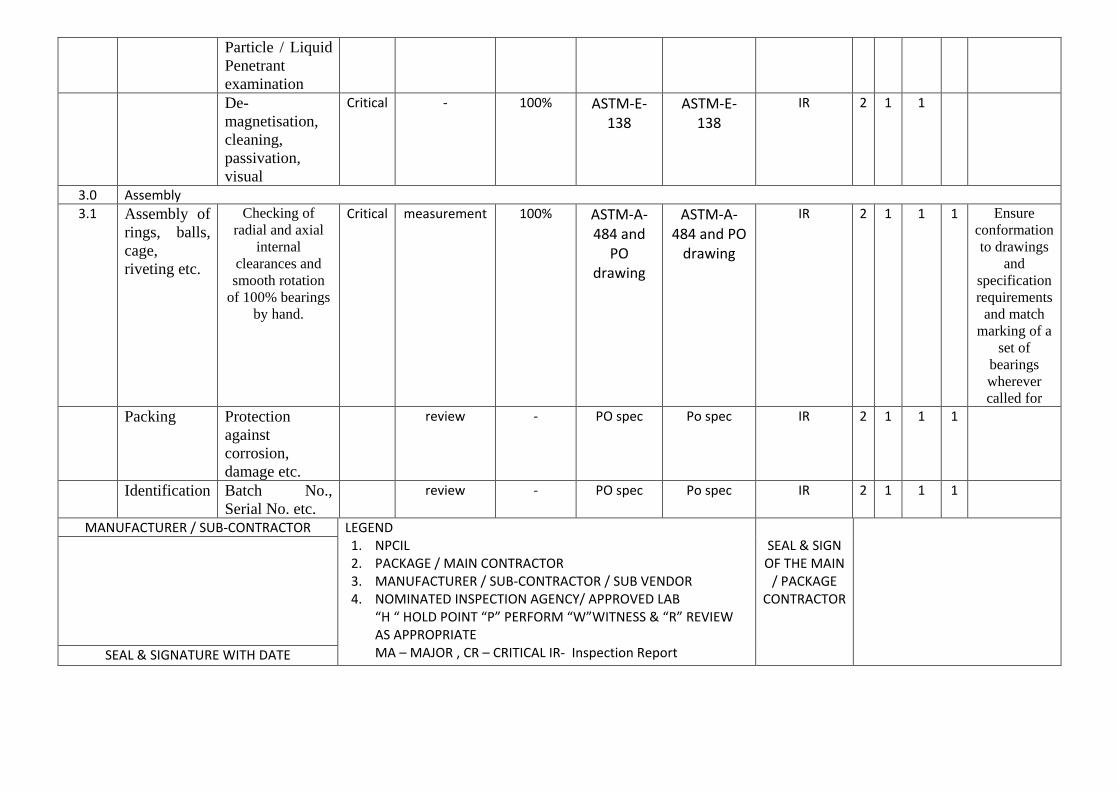
6.2.5 Assembly
a. Before assembly, balls, cages and rivets shall be thoroughly cleaned in petroleum spirit.
b. During and after the cleaning process, components shall not be touched with bare
hands. Clean hooks, tongs, gloves or suitable meshed sleeves shall be used.
c. After assembly of bearing, radial and axial internal clearances shall be checked and certified for conformity. The bearing shall be held suitably on the OD/ID and rotated with hand. The rotation shall be smooth without noise.
d. For bearings with riveted cages, the rivet head shall be correctly formed and shall
be free from cracks.
e. The following materials must not be allowed to contact the bearings or component parts during manufacture and assembly:
1. Zinc (also in the form of galvanizing or zinc rich paints). 2. Copper – also in sulphate form. 3. Aluminium 4. Cadmium – plated components 5. Mercury 6. Cerrabend 7. PVC 8. Neoprene 9. Fire retarded polythene 10. Chlorinated rubber - also in paint 11. Lead
NUCLEAR POWER CORPORATION OF INDIA LIMITED TECHNICAL SPECIFICATION FOR MANUFACTURE
OF WATER LUBRICATED BALL BEARINGS FOR FM HEAD OF 220 MWe PRESSURISED HEAVY WATER REACTORS (MAPS)
12. Felt tip pens. 7.0 QUALITY CONTROL REQUIREMENTS 7.1 General Requirements 7.1.1 Along with his quotation, the Supplier shall submit a brief quality control plan
indicating the various quality control measures that would be followed with regard to all aspects of the execution of the purchase order. Broadly, the quality control plan shall contain details of:
a. Quality control in case of raw material procurement. b. Incoming raw material inspection such as chemical and metallurgical analyses
that are to be carried out, mechanical properties required and non-destructive testing to be done.
c. Quality control during heat treatment of rings.
d. Non-destructive testing to be carried out after heat treatment such as hardness
testing, magnetic crack testing.
e. Dimensional control during manufacture and maintenance of dimensional records of the finished parts.
f. Quality control measures to be followed during assembly of bearings.
g. Quality control methods to be followed in packaging and transportation.
7.1.2 Dimensional Inspection: 100% visual and dimensional inspection, including inspection of geometric features
and surface finish, shall be performed on all dimensions of the components and their numerical values shall be recorded to ensure their conformance to the respective drawings. Deviation from dimensional and other requirements of the drawings shall form grounds for rejection of the components. These recorded dimensions shall be made available to the Purchaser for review. Manufacturer shall inspect the following and maintain a proper record of the same.
a) Dimensions, surface finish, geometric features, proper de-burring to ensure
absence of burrs and sharp corners, and alignment of all components b) Dimensional and functional checks of bearing assembly;
NUCLEAR POWER CORPORATION OF INDIA LIMITED TECHNICAL SPECIFICATION FOR MANUFACTURE
OF WATER LUBRICATED BALL BEARINGS FOR FM HEAD OF 220 MWe PRESSURISED HEAVY WATER REACTORS (MAPS)
c) Completeness and conformance of all components/assemblies to the requirements specified in this specification.
In certain cases, form tolerance such as run out, squareness and concentricity tolerances may be inspected and accepted on the basis of in-process inspection when the component is on the machine. In all cases where manufacturer desires to carry out quality control on the basis of in-process inspection, he shall obtain Purchaser’s prior approval and shall intimate Purchaser’s quality surveillance representative well in advance.
7.1.3 Quality Assurance Plan (QAP) Quality Assurance Plan for the work covered by this specification shall meet the
minimum requirement of control and test given in Appendix-2. However, after placement of Purchaser order, but prior to taking up manufacture, the Supplier shall submit a detail QAP covering all the aspects of manufacture and inspection of Water Lubricated Bearings for approval by Purchaser. This shall cover all the requirements of drawings and this specification. The final QAP as approved by Purchaser shall be used during manufacture.
7.1.4 Tra ceability of each bearing with respect to raw materials, heat treatment and
inspection reports is required. For this purpose, the Supplier shall suitably identify each bearing (or bearing set) by marking the bearing (or bearing set) serial number on the cage face. All reports and certificates referred in para 8.3 shall have cross reference to this bearing identification number.
7.1.5 Quality surveillance relating to the supply of WLB shall be carried out by the
Purchaser or his authorized representative. Quality surveillance during manufacture, inspection, assembly and testing will be carried out by the Purchaser or his authorized representative. The address of the Purchaser’s Quality Surveillance agent will be indicated after placement of purchase order. The Supplier shall provide all the necessary facilities to the Purchaser or his authorized representative for carrying out the quality surveillance.
7.2 Inspection and Test Failure: If any component fails to meet any inspection or test requirement of this specification
and if the Supplier intends to offer the equipment or the part for acceptance, either in failed, reworked or repaired condition, then, he shall notify the Purchaser or his authorized representative of his intentions. For this purpose, the Supplier shall submit a ‘Design Concession Request’ (DCR) with full particulars and descriptions of the deviations and proposed method of rectification. The DCR suitably countersigned by the Supplier’s Chief Quality Control Executive shall be submitted to the Purchaser’s Quality surveillance representative who in turn will pass this on with his comments,
NUCLEAR POWER CORPORATION OF INDIA LIMITED TECHNICAL SPECIFICATION FOR MANUFACTURE
OF WATER LUBRICATED BALL BEARINGS FOR FM HEAD OF 220 MWe PRESSURISED HEAVY WATER REACTORS (MAPS)
to the Purchaser’s Design Engineering department. The rectification/or use of the component by the Supplier shall be taken up only after the approval of the DCR by the Purchaser. The failed equipment or part may be accepted at the discretion of the Purchaser, as deviated part, or required to be reworked, repaired, reinspected or totally rejected. Purchaser’s procedure ED-PROC-7 shall be followed in this regard.
8.0 PACKING AND SHIPMENT 8.1 Bearings shall be individually packed in a polythene bag and sealed, then inserted and
sealed in another polythene bag. 8.2 A self adhesive label with the bearing designation and allocated serial number shall
be affixed to outside the sealed polythene bag before insertion into the outer polythene bag. These bags shall then be packed in cardboard boxes. The boxes shall be properly identified with suitable tags indicating the items and the quantity. The packing shall be of high quality and adequate to prevent damage during transit.
8.3 Prior to the actual shipment of the bearings, the Supplier shall submit all the test
results, inspection reports and certificates. The inspection reports and certificates required are as follows:
The Purchaser or his authorized representative will issue shipping release for the bearings based on these inspection reports and certificates. Among other requirements, these shall cover the following in particular:
Rings
1. Steel manufacturer’s cast number, chemical analysis details, non-destructive testing reports and results of metallurgical evaluation carried out for acceptance of the raw materials for manufacture of the bearing.
2. Heat treatment batch number, time, temperature, quenching and tempering
parameters, mechanical properties achieved and hardness test results.
3. 100% dimensional inspection report after finish machining.
4. Reports of fluorescent magnetic particle inspection after finish machining. Balls
1. Ball manufacturer’s cast number, chemical analysis details and results of
metallurgical evaluation carried out for acceptance of the balls. 2. Reports of triple axis radiography.
NUCLEAR POWER CORPORATION OF INDIA LIMITED TECHNICAL SPECIFICATION FOR MANUFACTURE
OF WATER LUBRICATED BALL BEARINGS FOR FM HEAD OF 220 MWe PRESSURISED HEAVY WATER REACTORS (MAPS)
3. Certification regarding the results of 100% inspection of size, grade, form and surface texture.
4. Certification regarding 100% visual examination at 1X.
5. Certification regarding visual inspection of samples from each lot at 10X. Details
of sampling plan followed shall be indicated.
6. Reports of crushing load test.
Cages and Rivets
1. Raw material manufacturer’s cast number, chemical analysis details, mechanical properties and results of non-destructive testing, metallurgical evaluation, etc. carried out for the acceptance of the raw material.
1. Certification regarding checks for internal clearance. 2. The actual static and dynamic load rating and the expected life for each size of the
bearing shall be indicated.
3. Certification regarding smooth and noise free rotation of the bearing. Certificate of Conformity
An overall certificate of conformity indicating the complete compliance of all
bearings to the requirements of drawings, specification and the Purchaser Order. The Purchaser or his authorized representative will issue shipping release for the
bearings based on these inspection reports and certificates. The Supplier shall ship the bearing consignment only after receiving the shipping release.
9.0 INFORMATION AND DOCUMENTS TO BE FURNISHED BY THE
SUPPLIER
9.1 Along With Quotation
a. The Supplier shall submit a brief list of work executed by him to standards and tolerances similar to those specified in this Tender Document. Also a list of
NUCLEAR POWER CORPORATION OF INDIA LIMITED TECHNICAL SPECIFICATION FOR MANUFACTURE
OF WATER LUBRICATED BALL BEARINGS FOR FM HEAD OF 220 MWe PRESSURISED HEAVY WATER REACTORS (MAPS)
machine tools and equipment including heat treatment furnaces and inspection equipments available with the Supplier shall be furnished.
b. Drawings of each water lubricated ball bearings indicating all the relevant
dimensional and material details shall be furnished by the Supplier. c. Details of inspection equipment and method of inspection of various features of
bearing rings, cage and balls shall be furnished by the Supplier d. Confirmation that Supplier will meet all the requirements indicated in the
drawings and this specification.
e. The Supplier shall clearly indicate in his quotation, the static load capacity, dynamic load capacity, expected life of each bearing. If bearing life requirements specified can not be achieved, then the Supplier shall indicate in his quotation the expected replacement frequency.
f. A brief quality control manual that would be followed during the execution of the
order (see para 7.1.1). 9.2 After the Placement of Purchase Order prior to taking up of manufacture of
Bearings
a. Detailed Quality Assurance Plan (QAP). b. Ultrasonic testing procedures for SS 440C material for bearing rings.
c. Heat treatment procedures for SS 440C material for bearing rings.
d. Fluorescent magnetic particle testing procedure for bearing rings.
e. Triple axis radiographic examination procedure for Balls.
f. Crushing load test procedure for Balls.
g. The manufacturing schedule with imminent check points.
h. Three sets of drawings of the water lubricated bearings specifying all details of
materials, dimensions etc. for Purchaser’s approval.
i. Packing procedures to be adopted. Manufacture of bearings shall be taken up only after obtaining clearance from the
Purchaser.
NUCLEAR POWER CORPORATION OF INDIA LIMITED TECHNICAL SPECIFICATION FOR MANUFACTURE
OF WATER LUBRICATED BALL BEARINGS FOR FM HEAD OF 220 MWe PRESSURISED HEAVY WATER REACTORS (MAPS)
9.3 At the Time of Final Shipment of Bearings All certificates, inspection reports, test results (see para 8.3) shall be furnished. 10.0 SUB-CONTRACTING Any or part of the work by the Supplier shall be sub-contracted only with the written
consent from the Purchaser. The Supplier shall be responsible to the Purchaser for all the work sub-contracted by him.
11.0 APPROVAL OF SUPPLIER’S DRAWINGS AND PROCEDURES BY THE
PURCHASER 11.1 As specified elsewhere in the specification, various manufacturing documents,
inspection reports, inspection procedures, manufacturing drawings etc. are to be submitted to the Purchaser by the Supplier. Verification and approval of the above is for the benefit of the Purchaser and shall not relieve the Supplier from full responsibility for ensuring correct interpretation of drawings and specifications or for the completeness and accuracy of the shop drawings and procedures submitted by the Supplier.
11.2 Waiving of quality requirements or acceptance of parts shall not relieve the Supplier
from the responsibility of furnishing parts and workmanship in accordance with the terms of the contract.
12.0 ADDITIONAL INSPECTION AND TESTS
In addition to the inspection and tests indicated in this specification, the Purchaser shall have the right to ask for additional inspection or testing as he deems necessary and the additional cost for such inspection and tests shall be borne by the Purchaser.
13.0 HISTORY DOCKET
The manufacturer shall furnish to the Purchaser five (5) copies of Inspection History Docket covering all aspects of manufacture, inspection and testing such as heat treatment records, mechanical testing records, dimensional inspection etc. All these documents shall be signed by a responsible technical person of the manufacturer.
14.0 WARRANTY
Warranty period for each assembly shall be 24 months from the date of shipment of Water lubricated Bearing or 6 months from the date of actual use whichever is earlier.
15.0 PURCHASER’S DRAWINGS, SPECIFICATIONS, SAMPLES ETC.
NUCLEAR POWER CORPORATION OF INDIA LIMITED TECHNICAL SPECIFICATION FOR MANUFACTURE
OF WATER LUBRICATED BALL BEARINGS FOR FM HEAD OF 220 MWe PRESSURISED HEAVY WATER REACTORS (MAPS)
All drawings, specifications, patterns, samples, models and prototypes that may be furnished to Supplier by Purchaser are the property of Purchaser and are intended to be complementary and to provide for and comprise every thing necessary for the completion of works/supply. These are not to be used for any works or performance other than those for which these have been provided and shall be returned to Purchaser immediately on completion of work/supply, in good condition.
15.2 Property of Purchaser
If, during the process of execution of the contact, any improvement, refinement or technical changes and modifications are effected by Supplier, such changes shall not affect the title to the property of Purchaser and all the information, specifications, drawings etc including the improvement/ modifications effected by Supplier shall continue to be the property of Purchaser. Supplier shall not have any claim or rights whatsoever in respect of Purchaser’s drawings, specifications, patterns, prototypes etc. even where improvement, refinement, modifications etc. have been effected by Supplier.
15.3 Confidential Information
The drawings, specifications, patterns, samples, models, prototypes and such other information furnished to Supplier relating to the supply/works, sub-system/equipment etc. are to be treated as confidential which shall be held by Supplier in confidence and shall not be divulged, transferred, exchanged, gifted or communicated to any third party without the prior written consent of Purchaser. Supplier therefore binds himself, his successors, heirs, executors, administrators, employees and the permitted assignees or such other persons or agents directly or indirectly concerned with the works/supply to the confidential nature of the drawings, specification, prototypes samples etc.
NUCLEAR POWER CORPORATION OF INDIA LIMITED TECHNICAL SPECIFICATION FOR MANUFACTURE
OF WATER LUBRICATED BALL BEARINGS FOR FM HEAD OF 220 MWe PRESSURISED HEAVY WATER REACTORS (MAPS)
TECHNICAL SPECIFICATION FOR SS 440C BARS FOR MANUFACTURE OF WATER LUBRICATED BEARINGS
1.0 SCOPE
This specification establishes the requirements for manufacture, inspection, testing and supply of Electro Slag Refined (ESR) or Consumable Electrode Vacuum Arc Re-melted (CVAR) quality 440C Stainless Steel Bars for manufacture of bearing rings of Water Lubricated Bearings.
2.0 STEEL MAKING PROCESS 2.1 The bars to be supplied as per this specification are to be made of 440C stainless
steel. The steel shall be made by a process that is capable of producing high quality product and shall be either Electro Slag Refined (ESR) or Consumable Electrode Vacuum Arc Re-melted (CVAR) quality to meet the requirements of this specification.
2.2 All bars shall be hot rolled /forged, rough machined or peeled. 2.3 Unless otherwise specified the dimensional tolerance of all the bars shall be governed
by the requirement of ASTM-A-484. 2.4 Bars shall be supplied in annealed condition. 3.0 INSPECTION & TESTING REQUIREMENTS 3.1 Chemical Analysis
Chemical analysis of each heat of steel shall be made in accordance with the test methods of ASTM-A-751. The steel shall conform to the following chemical composition: Carbon : 0.95 to 1.10 Manganese : 1.00 (max) Phosphorus : 0.025 (max.) Sulphur : 0.025 (max.) Silicon : 1.00 (max.) Chromium : 16.00 to 18.00 Nickel : 0.75 (max.) Copper : 0.50 (max.) Molybdenum : 0.40 to 0.65
NUCLEAR POWER CORPORATION OF INDIA LIMITED TECHNICAL SPECIFICATION FOR MANUFACTURE
OF WATER LUBRICATED BALL BEARINGS FOR FM HEAD OF 220 MWe PRESSURISED HEAVY WATER REACTORS (MAPS)
Two product samples shall be analysed at random for each heat in accordance with ASTM-A-751. The chemical composition as analysed shall meet the requirements specified above.
3.2 Macroetch Testing
Specimens representative of cross section of billets shall be macroetched and rated in accordance with Test Methods ASTM-E-381 acid and water (1:1) at 160 to 180o F (71 to 82oC). Acceptance standard shall be equal or better than: a. Plate-1 of ASTM-E-381
Sub-surface condition - S2 Random condition - R2 Centre segregation - C2
b. Plate-II of ASTM-E-381
1. Centrally located ring patterns up to a maximum of 60 mm dia only are acceptable.
2. Flute, cracks, gassy appearance, butt tears, splash, flakes, etc. are not acceptable to any degree.
3.3 Inclusion Rating Micro-inclusion rating tests shall be carried out in accordance to the methods
specified in ASTM-E-45. The average of the worst fields for each inclusion types for a heat shall be equal or better than:
A, B & C types of inclusion - 1.0 thin - 0.5 heavy D type of inclusion - 1.5 thin - 0.5 heavy 3.4 Response to Heat Treatment Specimens with sections 9.5 mm in thickness cut from a bar, billet, forging shall be
placed in a furnace that is at 1875 ± 10oF (1023.8 ± 5.5oC), allowed to heat to 1875 ± 10oF, held at this temperature for 25 minutes and cooled in still air. The hardness of such specimens shall not be less than 58 HRC. Also, samples heat treated as above shall show a fracture grain size of No.6 or finer.
NUCLEAR POWER CORPORATION OF INDIA LIMITED TECHNICAL SPECIFICATION FOR MANUFACTURE
OF WATER LUBRICATED BALL BEARINGS FOR FM HEAD OF 220 MWe PRESSURISED HEAVY WATER REACTORS (MAPS)
The steel shall be free of excessive carbide segregation and when annealed the steel shall have a spherodized micro structure and hardness shall be 255 BHN maximum.
3.6 Visual Inspection
Prior to packaging, all the bars that are ready for shipment shall be 100% visually examined for any cracks or other unacceptable injurious defects that can be visually seen. For acceptance, the bars shall not have any visual cracks or other injurious defects.
3.7 Non-Destructive Test Requirements 3.7.1 General
All non-destructive tests set forth below shall be carried out on the bars after completion of annealing and machining (centreless grinding /turning/peeling) operation.
3.7.2 Magnetic Particle Examination All bars of all sizes shall be inspected by wet magnetic particle examination in
accordance with ASTM-E-138. Acceptance standard shall be as follows:
a. Only indications with major dimension greater than 1.5 mm shall be considered relevant.
b. The following relevant indications are unacceptable: 1. Any linear indication greater than 1.5 mm long for bars less than 15 mm diameter,
greater than 3.1 mm long for bars from 15 mm diameter to under 50 mm diameter, and 4.7 mm long for bars 50 mm diameter and greater.
2. Rounded indications with dimensions greater than 3.1 mm for bar diameters less
than 15 mm and greater than 4.7 mm for bar diameter 15 mm and greater.
3. Four or more indications in a line separated by 1.5 mm or less edge to edge.
4. Ten or more indications in any 3800 sq.mm of area whose major dimensions is not more than 150 mm with the dimensions taken in the most unfavorable location relative to the indications being evaluated.
NUCLEAR POWER CORPORATION OF INDIA LIMITED TECHNICAL SPECIFICATION FOR MANUFACTURE
OF WATER LUBRICATED BALL BEARINGS FOR FM HEAD OF 220 MWe PRESSURISED HEAVY WATER REACTORS (MAPS)
c. Any indications in excess of the acceptance standards at para (b) above which is
believed to be non relevant shall be regarded as a defect and shall be re-examined to verify whether or not actual defects are present. No relevant indications and broad areas of pigmentation, which would mask indications of defects, are unacceptable.
d. All bars shall be demagnetized after magnetic particle examination. Residual
magnetism in the bars shall be less than 2 gausses. 3.7.3 Ultrasonic Examination All bars of size 50 mm diameters and above shall be 100% ultrasonically examined
over the entire surface. Ultrasonic examination of each bar shall be carried out in accordance with specifications ASTM-A-388 and ASTM-A-745 using straight beam technique from two directions approximately at right angles to each other. The entire volume of each bar shall be examined.
Acceptance Standard
Acceptance standard shall be as per reference block having defect standard of 2.0 mm diameter flat bottom hole. Indications from a defect more than that from 2.0 mm diameter flat bottom hole in the defect standard shall be a cause for rejection of the bar.
4.0 IDENTIFICATION AND MARKING OF BARS 4.1 Each bar shall be identified with the relevant heat number punched on both end faces
and logo. 5.0 TEST REPORTS TO BE FURNISHED BEFORE SHIPPING THE
MATERIAL Certificates, test reports and inspection reports signed by a responsible technical
representative of the Supplier covering all tests and analyses shall be furnished to the Purchaser. When inspection or testing is subcontracted to an outside agency the certificates/and reports shall be signed by a responsible technical representative of such agency and countersigned by the supplier.
The following certified test reports shall be furnished to the Purchaser and
Purchaser’s acceptance of material shall be obtained. All the test reports shall be appropriately co-related with the heat number and size of the bars.
NUCLEAR POWER CORPORATION OF INDIA LIMITED TECHNICAL SPECIFICATION FOR MANUFACTURE
OF WATER LUBRICATED BALL BEARINGS FOR FM HEAD OF 220 MWe PRESSURISED HEAVY WATER REACTORS (MAPS)
5.1 Steel melting process. 5.2 Test reports for chemical analysis as per para 3.1 above. 5.3 Test reports of macro-etch tests as per para 3.2 above. 5.4 Test reports of inclusion rating tests as per para 3.3 above. 5.5 Test reports of response to heat treatment as per para 3.4 above. 5.6 Test reports of microstructure and hardness as per para 3.5 above. 5.7 Certificate of visual examination that the bars supplied are free from visual defects
(para 3.6). 5.8 Test reports for magnetic particle and ultrasonic examinations carried out on each bar
(para 3.7). 5.9 Certificate stating that identification of bars has been done as per para 4.0 above. 5.10 Certificate of compliance. 6.0 QUALITY SURVEILLANCE 6.1 The overall quality control of procurement of the bars shall be the responsibility of
the water lubricated bearing supplier. However, the bars procured shall be subject to quality surveillance by Purchaser or his authorized representative by verification/witness of inspection / test reports of chemical analysis and mechanical/NDT tests.
6.2 Clearance shall be obtained from Purchaser or his authorized representative before
taking up the machining of these bars. 6.3 Items found unsatisfactory as per the requirements of this specification or items with
any defects beyond acceptable limits specified, showing up during machining, shall be replaced by water lubricated bearing supplier by items which are satisfactory.
6.4 Bars found unsatisfactory as to workmanship or material shall be removed by the
supplier and replaced by bars, which are satisfactory.
APPENDIX-2
NUCLEAR POWER CORPORATION OF INDIA LIMITED PR-PROC-14(Rev- 01)
P.O. No. (MAIN CONTRACTOR / SUB – VENDORE AS APPLICABLE) DATE
QUALITY ASSURANCE PLAN
QAP NO.: NPCIL/PROJECT/USI/ITEM/SL.NO.
ITEM : Water Lubricated Ball bearings
PROJECT
NAME OF THE PACKAGE PO NO. : (NPCIL)
NPCIL QA REF. NO. :
DATA SHEETS/VSS NO./ DRG NO.
ITEM BRIEF DESCRIPTION
DESIGN CODE/ SPEC. NO.
FOR MAIN CONTRACTOR’S VENDOR AFFIX STAMP OF MAIN SUB-VENDOR
PREPARED BY CHECKED / REVIEWED BY
APPROVED BY
SIGNATURE
NAME
DATE
FOR PACKAGE / MAIN CONTRACTOR’S VENDOR
AFFIX STAMP OF PACKAGE CONTRACTOR
FOR NPCIL
CHECKED BY REVIEWED BY APPROVED BY CHECKED BY REVIEWED BY APPROVED BY
SIGNATURE SIGNATURE
NAME NAME
SME (F) MS DATE DATE
NPCIL
SUB VENDOR/SUB CONTRACTOR / MANUFACTURERS NAME & ADDRESS
QUALITY ASSURANCE PLAN PROJECT :MAPS KALPAKKAM
ITEM Water Lubricated Ball bearings NAME OF THE PACKAGE & MAIN CONTRACTOR QAPNO. & REV No. & DATE