1 Annexure 1 TECHNICAL SPECIFICATIONS AND GTP ACCC DRAKE HTLS CONDUCTOR (FOR 220kV DOUBLE CIRCUIT TRANSMISISON LINE FROM WADAKKANCHERY – KUNNAMKULAM UNDER THRISSIVAPERUR LINE STRENGHTING PACKAGE PHASE 1 IN THRISSUR DISTRICT)
Transcript
1
Annexure 1
TECHNICAL SPECIFICATIONS AND GTP
ACCC DRAKE HTLS CONDUCTOR
(FOR 220kV DOUBLE CIRCUIT TRANSMISISON LINE FROM
WADAKKANCHERY – KUNNAMKULAM UNDER THRISSIVAPERUR
LINE STRENGHTING PACKAGE PHASE 1 IN THRISSUR DISTRICT)
2
TABLE OF CONTENT
SR. NO. DESCRIPTION
PAGE
1 SCOPE 3
2 STANDARD 3
3 SITE CLIMATIC CONDITIONS 5
4 SYSTEM CONDITION 6
5 TECHNICAL DETAILS OF CONDUCTOR 6
6 MATERIAL & WORKMANSHIP 7
7 TEST ON CONDUCTORS 9
8 PACKING 12
9 ANNEXURE-A 15
10 GUARANTEED TECHNICAL PARTICULARS OF ACCC DRAKE CONDUCTOR
20
3
1 SCOPE
This section provides the technical details of HTLS Conductors for use on 220kV DC transmission lines. The material and services under this specification shall be performed as per the requirements of the latest revisions and amendments available at the time of placement of order of all the relevant Indian Standards/Codes listed in Clause-2 STANDARDS hereunder or equivalent International Standards, except as modified in this document.
The materials covered here under this specification shall be supplied complete in all respects, including all components, fittings and accessories which are necessary or are usual for their efficient performance and satisfactory maintenance under the various operating and atmospheric conditions. Such parts shall be deemed to be within the scope of the Contract, whether specifically included or not in the Specification or in the Contract Schedules.
2 STANDARDS
Sl. No. Indian Standard
Title International Standard
1. IS: 209-1992 Specification for zinc BS:3436-1986
2. IS: 398-1982 Specification for Aluminium Conductors for Overhead Transmission Purposes
22 Standard Specification for Extra-High-Strength and Ultra-High-Strength Zinc-Coated (Galvanized) Steel Core Wire for Overhead Electrical Conductors.
ASTM B 957 (200⁰C)
The standards mentioned above are available from:
Reference Abbreviation Name and Address
BS British Standards, British Standards Institution 101, Pentonvile Road, N - 19-ND, UK
IEC/CISPR International Electro technical Commission, Bureau Central de la Commission, electro Technique international, 1 Rue de verembe, Geneva, SWITZERLAND
BIS/IS Bureau Of Indian Standards. Manak Bhavan, 9, Bahadur Shah Zafar Marg, New Delhi – 110001, INDIA
5
ISO International Organisation for Standardization. Danish Board of Standardization Danish Standardizing Sraat, Aurehoegvej-12 DK-2900, Heeleprup, DENMARK.
ASTM ASTM Headquarters 100 Barr Harbor Drive PO Box C700 West Conshohocken, PA 19428-2959, USA
Material meeting with the requirements of other authoritative standards, which
ensure equal or better performance than the standards mentioned above, shall also be considered. When the material offered by the bidder conforms to other standards, salient points of difference between standards adopted & the standards specified in this specification shall be clearly brought out in the relevant schedules. Three copies of such standards with authentic translation in English shall be furnished along with the bid.
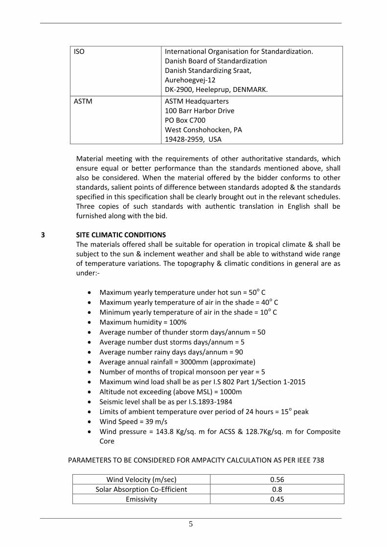
3 SITE CLIMATIC CONDITIONS The materials offered shall be suitable for operation in tropical climate & shall be
subject to the sun & inclement weather and shall be able to withstand wide range of temperature variations. The topography & climatic conditions in general are as under:-
Maximum yearly temperature under hot sun = 50o C
Maximum yearly temperature of air in the shade = 40o C
Minimum yearly temperature of air in the shade = 10o C
Maximum humidity = 100%
Average number of thunder storm days/annum = 50
Average number dust storms days/annum = 5
Average number rainy days days/annum = 90
Average annual rainfall = 3000mm (approximate)
Number of months of tropical monsoon per year = 5
Maximum wind load shall be as per I.S 802 Part 1/Section 1-2015
Altitude not exceeding (above MSL) = 1000m
Seismic level shall be as per I.S.1893-1984
Limits of ambient temperature over period of 24 hours = 15o peak
Wind Speed = 39 m/s
Wind pressure = 143.8 Kg/sq. m for ACSS & 128.7Kg/sq. m for Composite Core
PARAMETERS TO BE CONSIDERED FOR AMPACITY CALCULATION AS PER IEEE 738
Wind Velocity (m/sec) 0.56
Solar Absorption Co-Efficient 0.8
Emissivity 0.45
6
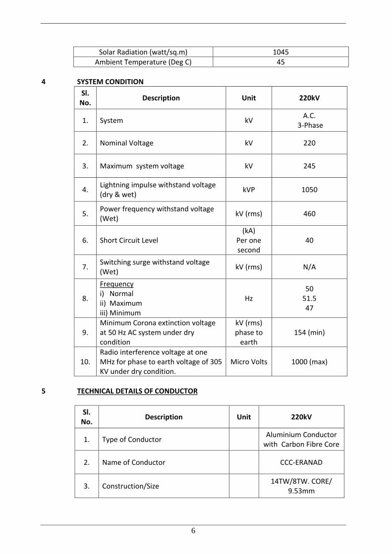
Solar Radiation (watt/sq.m) 1045
Ambient Temperature (Deg C) 45
4 SYSTEM CONDITION
Sl. No.
Description Unit 220kV
1. System kV A.C.
3-Phase
2. Nominal Voltage kV 220
3. Maximum system voltage kV 245
4. Lightning impulse withstand voltage (dry & wet)
kVP 1050
5. Power frequency withstand voltage (Wet)
kV (rms) 460
6. Short Circuit Level (kA)
Per one second
40
7. Switching surge withstand voltage (Wet)
kV (rms) N/A
8.
Frequency i) Normal ii) Maximum iii) Minimum
Hz 50
51.5 47
9. Minimum Corona extinction voltage at 50 Hz AC system under dry condition
kV (rms) phase to
earth 154 (min)
10. Radio interference voltage at one MHz for phase to earth voltage of 305 KV under dry condition.
Micro Volts 1000 (max)
5 TECHNICAL DETAILS OF CONDUCTOR
Sl. No.
Description Unit 220kV
1. Type of Conductor Aluminium Conductor
with Carbon Fibre Core
2. Name of Conductor CCC-ERANAD
3. Construction/Size 14TW/8TW. CORE/
9.53mm
7
4. Number of Conductor per Phase Nos. 1
5. Spacing between conductor of same phase (sub conductor spacing)
mm N/A
6. Nominal Overall Diameter mm 28.14
7.
Cross Section Area Aluminium =
Steel/Composite Core = Total =
mm2
512.10 71.30
583.40
8.
Nominal Weight Aluminium =
Steel/Composite Core = Grease =
Total =
Kg/Km
1415 132
0 1547
9. Modulus of Elasticity a) Aluminium / AL. Alloy b) Core
GPa
58 112.3
10. Co-efficient of Linear Expansion a) Aluminium / AL. Alloy b) Core
/ 0C
0.000023 0.00000161
11. Ultimate Tensile Strength KN 153.80
12. DC resistance at 20°C Ω/km 0.05460
13. Current Carrying Capacity at max operating temp.
Amp 1503
14. Maximum Operating Temperature 0C 175
6 MATERIAL & WORKMANSHIP 6.0.1 The material offered shall be of best quality and workmanship. The Aluminum
conductor strands will consist outer stranding of fully annealed aluminum wire of 1350-O & inner core shall be composite core for 220kV conductors.
6.0.2 6.0.3 Inner solid core for 220kV conductor shall be made of composite material like glass
& carbon fibre. It shall have properties conforming to the technical performance requirement of finished conductor. Bidder shall furnish properties and composition of the solid composite core in the GTP schedule. The composite material for core shall be of such proven quality that its properties are not deteriorated by the normal operating conditions of 220kV transmission line in tropical environment conditions.
8
6.0.4 All the Aluminium, steel strands & composite core shall be smooth, uniform and free from all imperfections, such as spills and splits, die marks, scratches, abrasions, etc., after drawing and also after stranding.
6.0.5 The finished conductor shall be smooth, compact, uniform and free from all
imperfections including kinks (protrusion of wires), wire cross over, over riding, looseness (wire being dislocated by finger/hand pressure and/or unusual bangle noise on tapping), material inclusions, white rust, powder formation or black spot (on account of reaction with trapped rain water etc.), dirt, grit etc.
6.0.7 The steel strands shall be preformed and post formed in order to prevent
spreading of strands in the event of cutting of core wire. Care shall be taken to avoid, damages to galvanization during pre-forming and post-forming operation.
6.1 JOINTS IN WIRES 6.1.1 Aluminium Wires During stranding, no aluminium wire welds shall be made for the purpose of
achieving the required conductor length. No joints shall be permitted in the individual wires in the outer most layer of the
finished conductor. However Joints in the inner layers are permitted in addition to those made in the base rod or wire before final drawing, but no two such joints shall be less than 15 meters apart in the complete stranded conductor.
Joints shall be made by cold pressure butt welding and shall withstand a stress of not less than the breaking strength of individual strand guaranteed.
6.1.2 Steel Wires There shall be no joint of any kind in the finished wire entering into the
manufacture of the strand. There shall also be no strand joints or strand splices in any length of the completed stranded steel core of the conductor.
6.1.2 Composite core There shall be no joints except those in the base rod before final drawing. It shall not been permitted in composite core in order to avoid reduction in the breaking strength of the conductor that may occur as a result of failure of the joints.
6.2 STRANDING For all, constructions, each alternate layer shall be stranded in opposite directions.
The wires in each layer shall be evenly and closely stranded round the under laying wire or wires. The final layer of wires shall have a right hand lay.
6.3 STANDARD LENGTH 6.3.1 The standard length of the conductor shall be 2000 meters. A tolerance of +/-5%
on the standard length offered by the Bidder shall be permitted. All lengths outside this limit of tolerance shall be treated as random lengths.
6.3.2 Random lengths will be accepted provided no length is less than 70% of the
standard length and the total quantity of such random lengths shall not be more than 10% of the total quantity ordered.
9
6.3.3 Bidder shall also indicate the maximum single length, above the standard length, he can manufacture in the guaranteed technical particulars of offer. This is required for special stretches like river crossing etc. The Owner reserves the right to place orders for the above lengths on the same terms and conditions applicable for the standard lengths during the pendency of the Contract.
6.4 TOLERANCES
Manufacturing tolerances on the dimensions to the extent of one percent shall be permitted for individual strands and the complete conductor.
7 TEST ON CONDUCTORS
The following tests should have been conducted in last five year for which offer is made. All the specified type tests on HTLS Conductors offered by the bidder shall not be required to be carried out if valid test certificate is available i.e., tests conducted in an accredited laboratory or witnessed by the representative (s) of a Utility. In the event of any discrepancy in the test report (i.e., any test report not applicable due to any design/ material/manufacturing process change including substitution of components or due to non compliance with the requirement stipulated in the Technical Specification) the tests shall be conducted by the Contractor at no extra cost to the KSEBL.
7.1 Type Tests I) On Complete Conductor
a) DC resistance test on stranded conductor : As per Annexure-A
b) UTS test on stranded conductor : As per Annexure-A
c) Stress- Strain test on stranded conductor and core at room temperature
: IEC 1089
d) Stress-strain test on stranded conductor and core at elevated temperature
: As per Annexure-A
e) High temperature endurance & creep test on stranded conductor
: As per Annexure-A
f) Sheaves Test : As per Annexure-A
g) Axial Impact Test : As per Annexure-A
h) Crush Strength Test : As per Annexure-A
i) Torsional Ductility Test : As per Annexure-A
j) Corona Extinction Voltage Test : As per Annexure-A
k) Radio Interference Voltage Test : As per Annexure-A
II) On Conductor Strand/ Core
a) Heat resistance test on Aluminium Alloy strands
: As per Annexure-A
10
b) Bending test on core : As per Annexure-A
c) Compression test on core : As per Annexure-A
d) Coefficient of linear expansion on core/ core strands
: As per Annexure-A
7.2 Acceptance Tests
a) Visual and dimensional check on drum : As per Annexure-A
b) Visual check for joints scratches etc. and length measurement of conductor by rewinding
: As per Annexure-A
c) Dimensional check on steel and aluminium strands
: As per Annexure-A
d) Check for lay-ratios of various layers : As per Annexure-A
e) Galvanizing test on core strands (if applicable) : As per Annexure-A
f) Aluminum thickness on aluminium clad wires (if applicable)
: As per Annexure-A
g) Torsion and Elongation tests on core strand/composite core
: As per Annexure-A
h) Breaking load test on core and Aluminium strands
: As per Annexure-A
i) Wrap test on core & Aluminium strands : IEC : 888 & 889
j) Minimum conductivity test on Conductor strands.
: IEC : 889
k) Heat resistance test on Aluminium Alloy strands
: As per Annexure-A
l) Ageing test on filler (if applicable) : As per Annexure-A
m) Minimum conductivity test on core strands( if applicable)
: As per Annexure-A
n) Procedure qualification test on welded joint of Aluminium strands
: As per Annexure-A
Note: All the above tests except (j) shall be carried out on aluminium and steel
strands after stranding only. 7.3 Routine Test
a) Check to ensure that the joints are as per Specification
b) Check that there are no cuts, fins etc., on the strands.
c) Check that drums are as per Specification
d) All acceptance test as mentioned above to be carried out on 10% of
11
drums
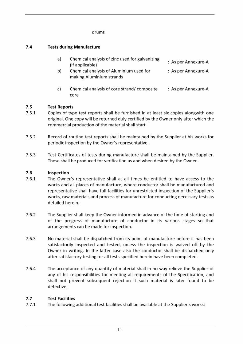
7.4 Tests during Manufacture
a) Chemical analysis of zinc used for galvanizing (if applicable)
: As per Annexure-A
b) Chemical analysis of Aluminium used for making Aluminium strands
: As per Annexure-A
c) Chemical analysis of core strand/ composite core
: As per Annexure-A
7.5 Test Reports 7.5.1 Copies of type test reports shall be furnished in at least six copies alongwith one
original. One copy will be returned duly certified by the Owner only after which the commercial production of the material shall start.
7.5.2 Record of routine test reports shall be maintained by the Supplier at his works for
periodic inspection by the Owner’s representative. 7.5.3 Test Certificates of tests during manufacture shall be maintained by the Supplier.
These shall be produced for verification as and when desired by the Owner. 7.6 Inspection 7.6.1 The Owner’s representative shall at all times be entitled to have access to the
works and all places of manufacture, where conductor shall be manufactured and representative shall have full facilities for unrestricted inspection of the Supplier’s works, raw materials and process of manufacture for conducting necessary tests as detailed herein.
7.6.2 The Supplier shall keep the Owner informed in advance of the time of starting and
of the progress of manufacture of conductor in its various stages so that arrangements can be made for inspection.
7.6.3 No material shall be dispatched from its point of manufacture before it has been
satisfactorily inspected and tested, unless the inspection is waived off by the Owner in writing. In the latter case also the conductor shall be dispatched only after satisfactory testing for all tests specified herein have been completed.
7.6.4 The acceptance of any quantity of material shall in no way relieve the Supplier of
any of his responsibilities for meeting all requirements of the Specification, and shall not prevent subsequent rejection it such material is later found to be defective.
7.7 Test Facilities 7.7.1 The following additional test facilities shall be available at the Supplier’s works:
12
a) Calibration of various testing and measuring equipment including tensile testing machine, resistance measurement facilities, burette, thermometer, barometer etc.
b) Standard resistance for calibration of resistance bridges. c) Finished conductor shall be checked for length verification and surface finish on
separate rewinding machine at reduced speed (variable from 8 to 16 meters per minute). The rewinding facilities shall have appropriate clutch system and free of vibrations, jerks etc. with traverse laying facilities.
8 PACKING 8.0.1 The conductor shall be supplied in non-returnable, strong, wooden drums provided
with lagging of adequate strength, constructed to protect the conductor against all damage and displacement during transit, storage and subsequent handling and stringing operations in the field. The Supplier shall be responsible for any loss or damage during transportation handling and storage due to improper packing. The drums shall generally conform to IS: 1778, except as otherwise specified hereinafter.
8.0.2 The drums shall be suitable for wheel mounting and for letting off the conductor
under a minimum controlled tension of the order of 5 KN. 8.0.3 The Bidder should submit their proposed drum drawings alongwith the bid. 8.0.4 For conductor, one standard length shall be wound on each drum. 8.0.5 All wooden components shall be manufactured out of seasoned soft wood free
from defects that may materially weaken the component parts of the drums. Preservative treatment shall be applied to the entire drum with preservatives of a quality which is not harmful to the conductor.
8.0.6 The flanges shall be of two ply construction with each ply at right angles to the
adjacent ply and nailed together. The nails shall be driven from the inside face flange, punched and then clenched on the outer face. The thickness of each ply shall not vary by more than 3mm from that indicated in the figure. There shall be at least 3 nails per plank of ply with maximum nail spacing of 75mm. Where a slot is cut in the flange to receive the inner end of the conductor the entrance shall be in line with the periphery of the barrel.
8.0.7 The wooden battens used for making the barrel of the conductor shall be of
segmental type. These shall be nailed to the barrel supports with at least two nails. The battens shall be closely butted and shall provide a round barrel with smooth external surface. The edges of the battens shall be rounded or chamfered to avoid damage to the conductor.
8.0.8 Barrel studs shall be used for the construction of drums. The flanges shall be holed
and the barrel supports slotted to receive them. The barrel studs shall be threaded
13
over a length on either end, sufficient to accommodate washers, spindle plates and nuts for fixing flanges at the required spacing.
8.0.9 Normally, the nuts on the studs shall stand protruded of the flanges. All the nails
used on the inner surface of the flanges and the drum barrel shall be counter sunk. The ends of barrel shall generally be flushed with the top of the nuts.
8.0.10 The inner cheek of the flanges and drum barrel surface shall be painted with a
bitumen based paint. 8.0.11 Before reeling, card board or double corrugated or thick bituminized water-proof
bamboo paper shall be secured to the drum barrel and inside of flanges of the drum by means of a suitable commercial adhesive material. After reeling the conductor, the exposed surface of the outer layer of conductor shall be wrapped with water proof thick bituminized bamboo paper to preserve the conductor from dirt, grit and damage during transport and handling.
8.0.12 A minimum space of 75 mm for conductor shall be provided between the inner
surface of the external protective tagging and outer layer of the conductor. 8.0.13 Each batten shall be securely nailed across grains as far as possible to the flange,
edges with at least 2 nails per end. The length of the nails shall not be less than twice the thickness of the battens. The nails shall not protrude above the general surface and shall not have exposed sharp, edges or allow the battens to be released due to corrosion.
8.0.14 The nuts on the barrel studs shall be tack welded on the one side in order to fully
secure them. On the second end, a spring washer shall be used. 8.0.15 A steel collar shall be used to secure all barrel studs. This collar shall be located
between the washers and the steal drum and secured to the central steel plate by welding.
8.0.16 Outside the protective lagging, there shall be minimum of two binder consisting of
hoop iron/galvanised steel wire. Each protective lagging shall have two recesses to accommodate the binders.
8.0.17 The conductor ends shall be properly sealed and secured on the side of one of the
flanges to avoid loosening of the conductor layers during transit and handling. 8.0.18 As an alternative to wooden drum Bidder may also supply the conductors in non-
returnable painted steel drums. After preparation of steel surface according to IS:9954, synthetic enamel paint shall be applied after application of one coat of primer. Wooden/Steel drum will be treated at par for evaluation purpose and accordingly the Bidder should quote in the package.
8.1 Marking
14
Each drum shall have the following information stenciled on it in indelible ink alongwith other essential data:
(a) Contract/Award letter number. (b) Name and address of consignee. (c) Manufacturer’s name and address. (d) Drum number (e) Size of conductor (f) Length of conductor in meters (g) Arrow marking for unwinding (h) Position of the conductor ends (i) Distance between outer-most Layer of conductor and the inner surface of lagging. (k) Barrel diameter at three locations & an arrow marking at the location of the
measurement. (l) Number of turns in the outer most layer. (m) Gross weight of drum after putting lagging. (n) Tear weight of the drum without lagging. (o) Net weight of the conductor in the drum. (p) CIP/MICC No. The above should be indicated in the packing list also. 8.1.1 Verification of Conductor Length
The Owner reserves the right to verity the length of conductor after unreeling at least ten (10) percent of the drums in a lot offered for inspection.
15
ANNEXURE-A 1. TESTS ON CONDUCTOR 1.1 UTS Test on Stranded Conductor Circles perpendicular to the axis of the conductor shall be marked at two places on
a sample of conductor of minimum 5 m length between fixing arrangement suitably fixed by appropriate fittings on a tensile testing machine. The load shall be increased at a steady rate up to 50% of minimum specified UTS and held for one minute. The circles drawn shall not be distorted due to relative movement of strands. Thereafter the load shall be increased at steady rate to minimum UTS and held for one minute. The Conductor sample shall not fail during this period. The applied load shall then be increased until the failing load is reached and the value recorded.
1.2 Corona Extinction Voltage Test One sample of conductor of 5m length shall be strung. In case of twin conductor,
two samples shall be arranged with the actual sub-conductor spacing between them. This sample assembly when subjected to power frequency voltage shall have a corona extinction voltage of not less than 154 KV (rms) for 220 KV system line to ground under dry condition. There shall be no evidence of corona on any part of sample when all possible sources of corona are photographed in a darkened room. The test shall be conducted without corona control rings. The voltage shall be corrected for standard atmospheric conditions.
However, small corona rings shall be used to prevent corona in the end fittings. 1.3 Radio Interference Voltage Test Under the conditions as specified under (1.2) above, the insulator string along with
complete hardware fittings shall have a radio interference voltage level below 1000 micro volts at one MHz when subjected to 50 Hz AC voltage 154kV line to ground under dry condition for 220kV AC line. The test procedure shall be in accordance with IS: 8263/ IEC: 60437. The Test may be carried out with corona control rings and arcing horns.
1.4 D.C. Resistance Test on Stranded Conductor On a conductor sample of minimum 5m length two contact-clamps shall be fixed
with a predetermined bolt torque. The resistance shall be measured by a Kelvin double bridge or using micro ohm meter of suitable accuracy by placing the clamps initially zero meter and subsequently one meter apart. The test shall be repeated at least five times and the average value recorded. The value obtained shall be corrected to the value at 20⁰C as per IS: 398-(Part-IV)/(Part-V). The resistance corrected at 20deg C shall conform to the requirements of this Specification.
1.5 Coefficient of linear expansion for core/core strands The temperature and elongation on a sample shall be continuously measured and
recorded at interval of approximately 15 degree C from 15 degree C to maximum designed continuous operating temperature corresponding to rated current as of specification by changing the temperature by suitable means. Coefficient of linear expansion shall be determined from the measured results.
1.6 Breaking load test on Aluminium Alloy & Core strands and D.C Resistance test on Aluminium Alloy wire
16
The above tests shall be carried out as per IEC: 888/889 and the results shall meet the requirements of the specification.
1.7 Wrap test on Steel Core strand The wrap test on steel strands shall be meet the requirements of IEC: 888.0. In
case of aluminium clad core wire, the same shall be wrapped around a mandel of diameter of five times that of the strand to form a helix of eight turns. The strand shall be unwrapped. No breakage of strand shall occur.
1.8 Heat Resistance test on Aluminum Alloy wire (If Applicable) Breaking load test as per clause 1.5 above shall be carried out before and after
heating the sample in uniform heat furnace at 280 degC (+5/-3 degC) temperature for one hour. The breaking strength of the wire after heating shall not be less than the 90% of the breaking strength before heating.
1.9 Chemical Analysis of Aluminium Alloy and Core Samples taken from the Aluminium and core coils/strands shall be
chemically/spectrographically analyzed. The same shall be in conformity to the particulars guaranteed by the bidder so as to meet the requirements stated in this Specification.
1.10 Visual and Dimensional Check on Drums The drums shall be visually and dimensionally checked to ensure that they conform
to the approved drawings. 1.11 Visual Check for Joints, Scratches etc. Conductor drums shall be rewound in the presence of the Owner. The Owner shall
visually check for scratches, joints etc. and that the conductor generally conform to the requirements of this Specification. Ten percent (10%) drums from each lot shall be rewound in the presence of the Owner's representative.
1.12 Dimensional Check on Core Strands and Aluminium Alloy Strands The individual strands shall be dimensionally checked to ensure that they conform
to the requirement of this Specification. 1.13 Check for Lay-ratios of Various Layers The lay-ratios of various layers shall be checked to ensure that they conform to the
guaranteed values furnished by the Contractor. 1.14 Procedure Qualification test on welded Aluminium Alloy strands. Two Aluminium Alloy wire shall be welded as per the approved quality plan and
shall be subjected to tensile load. The breaking strength of the welded joint of the wire shall not be less than the guaranteed breaking strength of individual strands.
1.15 Chemical Analysis of Zinc Samples taken from the zinc ingots shall be chemically/ spectrographically
analyzed. The same shall be in conformity to the requirements stated in the Specification.
1.16 Galvanizing Test The test procedure shall be as specified in IEC : 888.0. The material shall conform
to the requirements of this Specification. The adherence of zinc shall be checked by wrapping around a mandrel four times the diameter of steel wire.
1.17 Torsion and Elongation Tests on Core Strands The test procedures shall be as per clause No. 10.3 of IEC 888.0. In torsion test, the
number of complete twists before fracture shall not be less than 18 on a length equal to 100 times the standard diameter of the strand. In case test sample length
17
is less or more than 100 times the stranded diameter of the strand, the minimum number of twists will be proportioned to the length and if number comes in the fraction then it will be rounded off to next higher whole number. In elongation test, the elongation of the strand shall not be less than 1.5% for a gauge length of 250 mm. In case of composite core HTLS conductor, the following procedure shall be applicable:- i) Elongation Test: - The elongation of the composite core sample at shall be determined using extensometer. The load along the core shall be gradually increased. The elongation achieved on reaching the tensile strength of the core shall not be less than the value guaranteed in the GTP. ii) Torsion Test: The purpose of the test is to determine the resilience of the composite core to twisting and to show that after the composite core has experienced the prescribed twisting, it will not crack or have a loss in tensile Strength due to the twisting. A sample length that is 170 times the diameter of the composite core being tested is mounted in the gripping fixtures. One grip shall then be fixed so that it does not twist and the other end shall be twisted a full 360 degrees and then fixed in this position for 2 minutes. Once the twist time is completed, the core is untwisted an inspected for any crazing or other damage. If no damage is observed, the composite core is then tensile tested to failure and the final load recorded. For the test to be accepted, the composite core must withstand at least 100% of its rated tensile strength. Two samples need to be completed in order to satisfy the testing requirement. Composite cores subjected to stranding and subsequent environmental exposure will have different physical and mechanical properties from those of the composite core in the as-manufactured state. If tests on composite cores are to be made after stranding, the purchaser and the manufacturer at the time of placing the order should agree on the properties to be met.
1.18 Bending test on conductor core strand A sample of conductor core strand measuring 30 cm in length shall be subject to
bending with help of a vise. The vised length of wire should be 5 cm and radius of bend 4.8 mm. The bending should be first 90 degrees left and 90 degree right. After this operation the strand should cut at the bending point. There should be no separation of core and aluminium at the bending point after this operation.
In Case of composite core sample shall be wrapped 180 degree around a
cylindrical mandrel, and the specimen brought to 15 % of the rated tensile strength of the composite core and held for 1 min. The mandrel diameter shall be not more than 50 times the dia of composite core. After completion of the test, the core shall withstand UTS test and dye penetration test.
1.19 Compression test on steel strand A sample of steel core strand 10 mm in length is to be compressed by a plate with
a load of 3600 kgs. The aluminium and core strand should not break.
18
1.20 Aluminium conductivity test on aluminium clad strand (If Applicable) Resistivity test as per IEC-468 shall be conducted to confirm minimum conductivity
as per specification requirement. 1.21 Minimum conductivity test on thermal resistant aluminium alloy strands (If
Applicable) Resistivity test as per IEC-468/IEC 889 shall be conducted to confirm minimum
conductivity as per specification requirement. 1.22 Stress-strain test at elevated temperature Stress-strain test as per IEC-1089 shall be conducted keeping conductor
temperature at designed maximum temperature. The guaranteed Core UTS shall be considered for performing the test.
1.23 High Temperature endurance & creep test A conductor sample of length equal to at least 100 X d + 2 X a (where, d is the
conductor diameter and a is the distance between the end fitting and the gauge length) shall be strung at tension equal to 25 % of conductor UTS. The distance, a, shall be at least 25 % of the gauge length or 2 m whichever is the smaller. The conductor sample shall be subjected to two tests as indicated below:
(i) The conductor temperature shall be maintained at 20 deg C for 1000 hours. The elongation/creep strain of the conductor during this period shall be measured and recorded at end of 1 hour, 10 hour, 100 hour and subsequently every 100 hour up to 1000 hours time period. (ii) The conductor temperature shall be increased to design maximum temperature in steps of 20 deg. C and thermal elongation of the conductor sample shall be measured & recorded at each step. The temperature shall be held at each step for sufficient duration for stabilization of temperature. Further, the temperature of the conductor shall be maintained at maximum designed continuous operating temperature (+10 Deg. C) for 1000 hours. The elongation/creep strain of the conductor during this period shall be measured and recorded at end of 1 hour, 10 hour, 100 hour and subsequently every 100 hour up to 1000 hours time period. After completion of the above, the core of the conductor sample shall be subjected to UTS test where the conductor core should achieve 95% of the guaranteed core UTS. The supplier shall plot the thermal elongation with temperature. In case of polymer composite core conductor, the flexural strength & glass transition temperature of the core shall also be evaluated and the same shall not be degraded by more than 10 % over the initial value. The supplier shall plot the thermal elongation with temperature.
The supplier shall furnish details of creep characteristic in respect of the conducted based on laboratory test and other laboratory investigations/ experimental conducted on similar type of conductor and shall indicate creep strain values corresponding to 1 month, 6 month, 1 year, 10 year & 20 year creep at everyday tension & continuous designed temperature as well as room temperature.
1.24 Axial Impact Test The conductor sample shall be suspended vertically and load applied by dropping a
650 Kg from an elevation of 4 meters above the sample. The impact velocity shall be not be less than 8 m/sec. with an initial pre-tension of 200 kgs. The curve for
19
load vs time shall be recorded and recorded load of failure for core shall not be less than UTS of core.
1.25 Crush Strength Test A section of conductor is to be crushed between two six inch steel platens. Load
shall be held at 350 Kgs for 1 minute and then released. All the core strands shall be subsequently disassembled and tensile tested. All the core strands shall exhibit full strength retention
1.26 Torsional Ductility Test The conductor sample of 10-15m shall be loaded to 20% of UTS and then loaded in
increasing steps of +/-180 deg, the core shall withstand at least 16 such rotation for steel core and there shall be no damage to steel core wires and incase of trapezoidal shaped conductor or composite conductor, after 4 rotations and after separation of aluminum strands, the aluminum wires shall be cut and removed from the conductor and the exposed core shall be twisted and shall withstand up to 16 rotations.
1.27 Sheaves Test (if required) The conductor sample of minimum length of 35 meter shall be tensioned at 22 % of the UTS and shall be passed through pulleys having diameter of 32 times that of the conductor with angle of 20 deg. between the pulleys. The conductor shall be passed over the pulleys 36 times a speed of 2 m/sec. After this test UTS test on the conductor shall be carried out. In case of polymer composite core conductors, the core shall be inspected for any sign of damage or cracking through dye penetration test as per ASTM D5117.
20
GUARANTEED TECHNICAL PARTICULARS OF ACCC DRAKE CONDUCTOR
Sl .No
Description Unit Bid Offer
1 Name & Address of Manufacturer N/A
2 Construction of conductor/Designation of conductor as per IEC:1089
N/A
3 PARTICULARS OF RAW MATERIALS
3.1 Outer layers
a) Applicable standards if any
B) Type of Aluminium alloy
c)Minimum purity of aluminium %
d) Maximum copper content %
e) Zincronium content
e.1) Maximum %
e.2) Minimum %
f) Other elements
f.1) Silicon %
f.2) Ferrus %
3.2 Inner core
a) Applicable standards. if any
b) Material of core
21
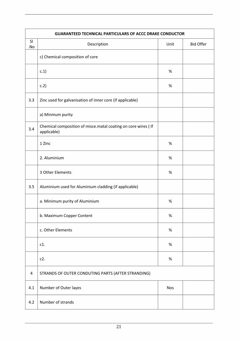
GUARANTEED TECHNICAL PARTICULARS OF ACCC DRAKE CONDUCTOR
Sl .No
Description Unit Bid Offer
c) Chemical composition of core
c.1) %
c.2) %
3.3 Zinc used for galvanisation of inner core (if applicable)
a) Minmum purity
3.4 Chemical composition of misce.matal coating on core wires ( If applicable)
1 Zinc %
2. Aluminium %
3 Other Elements %
3.5 Aluminium used for Aluminium cladding (if applicable)
a. Minimum purity of Aluminium %
b. Maximum Copper Content %
c. Other Elements %
c1. %
c2. %
4 STRANDS OF OUTER CONDUTING PARTS (AFTER STRANDING)
4.1 Number of Outer layes Nos
4.2 Number of strands
22
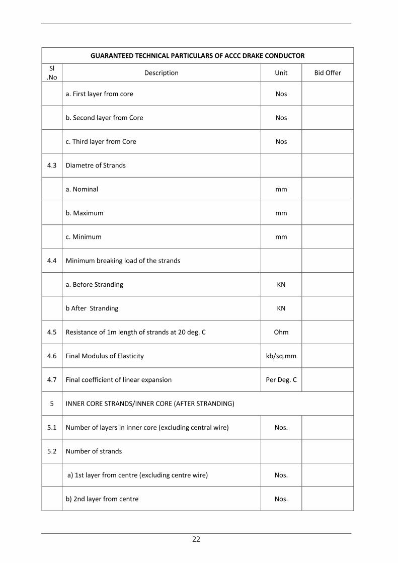
GUARANTEED TECHNICAL PARTICULARS OF ACCC DRAKE CONDUCTOR
Sl .No
Description Unit Bid Offer
a. First layer from core Nos
b. Second layer from Core Nos
c. Third layer from Core Nos
4.3 Diametre of Strands
a. Nominal mm
b. Maximum mm
c. Minimum mm
4.4 Minimum breaking load of the strands
a. Before Stranding KN
b After Stranding KN
4.5 Resistance of 1m length of strands at 20 deg. C Ohm
4.6 Final Modulus of Elasticity kb/sq.mm
4.7 Final coefficient of linear expansion Per Deg. C
5 INNER CORE STRANDS/INNER CORE (AFTER STRANDING)
5.1 Number of layers in inner core (excluding central wire) Nos.
5.2 Number of strands
a) 1st layer from centre (excluding centre wire) Nos.
b) 2nd layer from centre Nos.
23
GUARANTEED TECHNICAL PARTICULARS OF ACCC DRAKE CONDUCTOR
Sl .No
Description Unit Bid Offer
c) 3rd layer from centre Nos.
5.3 Diameter of strands
a)Nominal mm.
b)Maximum mm.
c)Minimum mm.
5.4 Minimum breaking load of strand
a)Before stranding KN
b)After stranding KN
5.5 Resistance of 1m length of strand at 20 deg C Ohm
5.6 Final modulus of elasticity KG/sq.mm
5.7 Final coefficient of linear expansion Per Deg. C
5.8 Aluminum cladding of core (if applicable)
a)thickness of claddding
1)Maximum mm
2)Minimum mm
b)Minimum no. of twists in a guage length equal to 100 times diameter of wire which the strands can withstand in the tortion test
1)before stranding Nos.
24
GUARANTEED TECHNICAL PARTICULARS OF ACCC DRAKE CONDUCTOR
Sl .No
Description Unit Bid Offer
2)After stranding Nos. Nos.
3)Minimum elongation of strand for gauge length of 250 mm %
4)Resistance of 1m length of strand at 20 deg C Ohm
5.9 Galvanising/Misce. metal coating(if applicable)
a)Minimum mass of zinc coating per sqm. of uncoated wire surface
gm
b)Minimum mass of misce. metal coating per sqm.of uncoated wire surface(if applicable)
gm
c)Min.no. of twists which a single strand shall withstand during torsion test for a length equal to 100 times dia of wire stranding
Number
d)Minimum elongation of strand for a gauge length of 250 mm mm
6 FILLER (if applicable)
6.1 Type & Designation of FILLER
6.2 Chemical composition of filler
6.3 Mass of filler Kg/km
7 COMPLETE ACCC CONDUCTOR (ASTM B 857/EN50540)
7.1 Cross section drawing of the offered conductor enclosed Yes/No
7.2 Diametre of Conductor
a. Nominal mm
b.Maximum mm
25
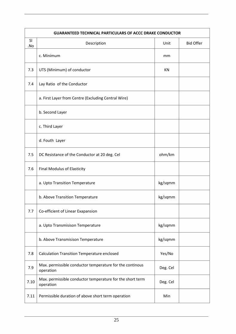
GUARANTEED TECHNICAL PARTICULARS OF ACCC DRAKE CONDUCTOR
Sl .No
Description Unit Bid Offer
c. Minimum mm
7.3 UTS (Minimum) of conductor KN
7.4 Lay Ratio of the Conductor
a. First Layer from Centre (Excluding Central Wire)
b. Second Layer
c. Third Layer
d. Fouth Layer
7.5 DC Resistance of the Conductor at 20 deg. Cel ohm/km
7.6 Final Modulus of Elasticity
a. Upto Transition Temperature kg/sqmm
b. Above Transition Temperature kg/sqmm
7.7 Co-efficient of Linear Exapansion
a. Upto Transmisison Temperature kg/sqmm
b. Above Transmisison Temperature kg/sqmm
7.8 Calculation Transition Temperature enclosed Yes/No
7.9 Max. permissible conductor temperature for the continous operation
Deg. Cel
7.10 Max. permissible conductor temperature for the short term operation
Deg. Cel
7.11 Permissible duration of above short term operation Min
26
GUARANTEED TECHNICAL PARTICULARS OF ACCC DRAKE CONDUCTOR
Sl .No
Description Unit Bid Offer
7.12 Steady state conductor rempearture at sepcified conductor current of .. ..AMPS and under ambient conditions
Deg. Cel
7.13 AC Resistance at Maximum continuous operating temperature corresponding to specified maximum operating current
Ohm/km
7.14 AC Resistance at Maximum continuous operating temperature corresponding to specified operating current
Ohm/km
7.15 Details of Creep characteristic for HTLS conductor enslosed Yes/No
7.16 Sag Tension calculation
1. Sag Tension Calculation enslosed Yes/No
2. Tenson at 32 deg. C and no wind kg
3. Sag and tension and maximum continuous operating temperature
metre and kg
Tension for followng conditions oepration
1) 32 deg. C and full wind condition kg
2) 32 deg.c and nil wind conditon kg
3) Minimum temp and 36 % of the full wind conditions kg
4) 32 dwg. C and 75 % full wind conditions kg
7.17 Direction of lay for outside layer
7.18 Linear mass of the conductor
a. Standard Kg/km
b. Minimum Kg/km
27
GUARANTEED TECHNICAL PARTICULARS OF ACCC DRAKE CONDUCTOR
Sl .No
Description Unit Bid Offer
c. Maximum Kg/km
7.19 Standard length of conductor Metre
7.20 Maximum length of conductor that can be offered as single length
metre
7.21 Tolerance of standard length of conductor %
7.22 Drum is as per the specification Yes/No
7.23 Nominal cross sectional area of conductor
a. Aluminium Sq.mm
b.Core Sq.mm
c. Total Sq.mm
7.24 Nominal wirght of the conductor
a. Aluminium Kg/km
b. Steel/Composite core Kg/km
c. Grease Kg/km
d. Total Kg/km
7.25 Current carrying capacity at maximum operating temperature Amps
7.26 Maximum operating temperature Deg. Cel
7.27 Any other details which are relevant as per Indian and international standards
28
GUARANTEED TECHNICAL PARTICULARS OF ACCC DRAKE CONDUCTOR