Page 1 of 107 ANNEXURE TO TENDER NO. DPS/MRPU/NRPP/FAB/1445/TPT-1126 Description of item: Detailed design of components, preparation of fabrication drawing, machining, fabrication, assembly of enclosure, installation of inside equipments and piping, functional testing & inspection at supplier’s premises, shipping to site, final installation and commissioning of a remote head metering pump (RHMP) Enclosure Train including supply of non – FIM items required for the work as per attached technical specifications and drawings for the project P3A at Kalpakkam. Sl. No. Item Description Qty. 1. RHMP Enclosure Train with 1 No. Strainer Cartridge Transfer Cask and 2 Nos. Multi Cartridge Disposal Casks. 1 No. NOTE: Tenderers who are willing to respond for the subject tender, may contact with full details on email - [email protected], [email protected], [email protected],[email protected]to get the details of pre-bid meeting before submission of technical and price bids. Technical Specifications for RHMP Enclosure Train CONTENTS INTRODUCTION: ................................................................................................................... 3 BRIEF DESCRIPTION: ........................................................................................................... 3 TABLE – 1: RHMP ENCLOSURE TRAIN CELL DIMENSIONS ............................................. 8 GENERAL CONSTRUCTION DETAILS: .............................................................................. 12 SHIELDED CASK FOR CARTRIDGE TRANSFER .............................................................. 14 SHIELDED CASK FOR MULTI CARTRIDGE DISPOSAL .................................................... 16 FABRICATION / MACHINING REQUIREMENTS: . ............................................................. 20 INSPECTION AND TESTING REQUIREMENTS ................................................................. 22 CLEANING AND PAINTING: ............................................................................................... 24 ACCEPTANCE CRITERIA: .................................................................................................. 24 SCOPE: . .............................................................................................................................. 24 TABLE – 2: LIST OF DRTAWINGS ...................................................................................... 24 FABRICATION OF A BAY MODULE: . ................................................................................. 26 FINAL MANUFACTURE:. ..................................................................................................... 26 FABRICATION OF SHIELDING BLOCKS: . ......................................................................... 26 FABRICATION, MACHINING AND ASSEMBLY: . .............................................................. 27 TABLE – 3 SAMPLE ESTIMATION OF PIPE WELDS IN RHMP ENCLOSURE TRAINS ... 30 TABLE – 4: APPROXIMATE PIPE FITTINGS REQUIREMENT........................................... 31 TABLE – 5: EQUIPMENT LISTING: ..................................................................................... 31 INSTALLATION AT SITE:..................................................................................................... 34 APPLICABLE STANDARDS & CODES: ............................................................................... 36 GENERAL REQUIREMENTS: .............................................................................................. 36
Transcript
Page 1 of 107
ANNEXURE TO TENDER NO. DPS/MRPU/NRPP/FAB/1445/TPT-1126
Description of item: Detailed design of components, preparation of fabrication drawing, machining, fabrication, assembly of enclosure, installation of inside equipments and piping, functional testing & inspection at supplier’s premises, shipping to site, final installation and commissioning of a remote head metering pump (RHMP) Enclosure Train including supply of non – FIM items required for the work as per attached technical specifications and drawings for the project P3A at Kalpakkam.
Sl. No. Item Description Qty.
1. RHMP Enclosure Train with 1 No. Strainer Cartridge Transfer Cask and 2 Nos. Multi Cartridge Disposal Casks.
CONTENTS INTRODUCTION: ................................................................................................................... 3 BRIEF DESCRIPTION:........................................................................................................... 3 TABLE – 1: RHMP ENCLOSURE TRAIN CELL DIMENSIONS ............................................. 8 GENERAL CONSTRUCTION DETAILS:.............................................................................. 12 SHIELDED CASK FOR CARTRIDGE TRANSFER .............................................................. 14 SHIELDED CASK FOR MULTI CARTRIDGE DISPOSAL.................................................... 16 FABRICATION / MACHINING REQUIREMENTS: . ............................................................. 20 INSPECTION AND TESTING REQUIREMENTS................................................................. 22 CLEANING AND PAINTING: ............................................................................................... 24 ACCEPTANCE CRITERIA: .................................................................................................. 24 SCOPE: . .............................................................................................................................. 24 TABLE – 2: LIST OF DRTAWINGS ...................................................................................... 24 FABRICATION OF A BAY MODULE: . ................................................................................. 26 FINAL MANUFACTURE:. ..................................................................................................... 26 FABRICATION OF SHIELDING BLOCKS: . ......................................................................... 26 FABRICATION, MACHINING AND ASSEMBLY: . .............................................................. 27 TABLE – 3 SAMPLE ESTIMATION OF PIPE WELDS IN RHMP ENCLOSURE TRAINS ... 30 TABLE – 4: APPROXIMATE PIPE FITTINGS REQUIREMENT........................................... 31 TABLE – 5: EQUIPMENT LISTING: ..................................................................................... 31 INSTALLATION AT SITE:..................................................................................................... 34 APPLICABLE STANDARDS & CODES:............................................................................... 36 GENERAL REQUIREMENTS:.............................................................................................. 36
Page 2 of 107
MATERIAL ............................................................................................................................ 38 INSPECTION AND TESTING REQUIREMENTS................................................................. 40 PACKING SUPPLY AND INSTALLATION:. ......................................................................... 41 QUALITY CONTROL DOCUMENTATION: .......................................................................... 42 DELIVERY AND MANUFACTURING SCHEDULE:. ............................................................ 42 DOCUMENTS TO BE FURNISHED AFTER AWARD OF CONTRACT: .............................. 43 FINAL DOCUMENTATION: ; ................................................................................................ 43 APPENDIX 1:TECHNICAL SPECIFICATIONS - WELDING & WELDING PROCEDURE ... 45 APPENDIX 2: LIQUID PENETRANT EXAMINATION PROCEDURE .................................. 56 APPENDIX 3: SPECIFICATIONS FOR RADIOGRAPHIC EXAMINATION.......................... 58 APPENDIX 4: TECH. SPEC. FOR PAINTING OF STRUCTURES ...................................... 61 APPENDIX 5: TESTING DURING SURFACE TREATMENT............................................... 63 APPENDIX 6: FIELD WELDING OF PIPING........................................................................ 64 APPENDIX 7: CLEANING METHODS FOR PIPING............................................................ 72 APPENDIX 8: LED LIGHTING SPECIFICATIONS............................................................... 74 APPENDIX 9: INSTALLATION PROCEDURE FOR BSBOV ............................................... 75 APPENDIX 10: FIM CONSOLIDATED LIST......................................................................... 76 APPENDIX 11: ITEMS TO BE TESTED & SUPPLIED......................................................... 77 APPENDIX 12: VENDOR EVALUATION.............................................................................. 78 ANNEXURES........................................................................................................................ 86 ANNEXURE 1: QUESTIONNAIRE ....................................................................................... 89 ANNEXURE 2: VENDOR EVALUATION PERFORMA ........................................................ 89 ANNEXURE 3:: ACCEPTANCE TO COMPLY WITH SPECIFICATIONS ............................ 90 ANNEXURE 4: ORGANISATIONAL STRUCTURE.............................................................. 91 ANNEXURE 5: EXPERIENCE IN NUCLEAR INSTALLATIONS. ......................................... 92 ANNEXURE 6: EXPERIENCE IN CHEMICAL INDUSSTRY................................................ 93 ANNEXURE 7: PROOF OF ABILITY OF THE VENDOR ..................................................... 94 ANNEXURE 8: LIST OF TYPICAL PLANT AND MACHINERY............................................ 96 ANNEXURE 9:: MACHINERY DETAILS ........................................................................... 97 ANNEXURE 10: QUALITY ASSURANCE SET-UP .............................................................. 98 ANNEXURE 11: SUB CONTRACTORS............................................................................... 99 ANNEXURE 12: INFORMATION TO BE SUBITTED WITH THE TENDER ....................... 100 ANNEXURE 13: LIST OF FREE ISSUE MATERIAL .......................................................... 102 ANNEXURE 14: P R I C E & S C H E D U L E OF ............................................................. 103 ANNEXURE 14 (Contd.) ..................................................................................................... 104 ANNEXURE 15: CONTRACT WORKS EXECUTED LAST 5 YEARS................................ 105 ANNEXURE 16: PARTICULARS OF CONTRACT WORKS IN HAND............................... 106 ANNEXURE 17: PARTICULARS OF EMPLOYEES FOR LAST 3 YEARS........................ 107
Page 3 of 107
RHMP ENCLOSURE TRAIN FOR PROJECT P3-A TENDER TECHNICAL SPECIFICATION
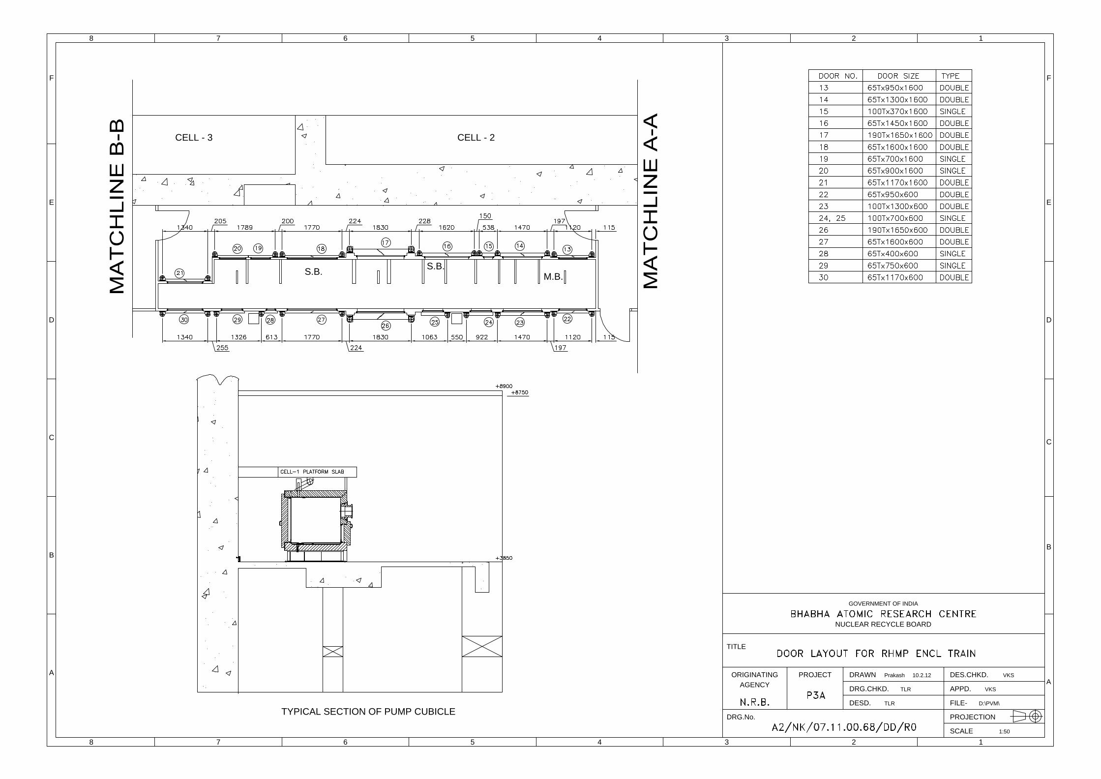
INTRODUCTION: This specification covers the requirements for the preparation of parts drawing including detailed design, machining & fabrication of components, assembly of enclosure, installation of inside equipment and piping, functional testing & inspection at supplier’s premises, shipping to site, final installation and commissioning of a remote operation & maintenance type RHMP Enclosure Train including supply of non – FIM items required for work as per the attached drawings and technical specifications for project P3A Kalpakkam. All the required SS / CS plates, pipes & structural sections, pumps, valves, RSW glasses and remote connectors will be provided by the department as free issue material (FIM) whereas all other items required for the work shall be supplied by the contractor. The machined heavily shielded RHMP Enclosure Train is meant for remote maintenance of remote head metering pumps. Remote module carriers (RMC) will be procured and installed in the RHMP Enclosure Train by the department after final commissioning of the system. All internal dimensional accuracies for positioning of the remote head modules and remote operable strainers shall be well within the required tolerances for remote operations. The procurement, certification of material and preparation of fabrication drawings shall also be in the scope of vendor. Fabrication, assembly, testing, installation and commissioning shall conform to the approved drawings and specifications laid down by the indentor. The product shall be made to high standards of engineering and workmanship to the complete satisfaction of the purchaser. The list of all the items issued by the department as FIM is given in Annexure 13 of this specification. Remaining materials as pipe fittings, fasteners, seals etc. as required shall be procured by the vendor for manufacture of RHMP Enclosure Trains and shall confirm the enclosed technical specifications and requirements. BRIEF DESCRIPTION: This tender covers manufacture of a machined MS heavily shielded RHMP Enclosure Train consisting of a series of varying thickness and internally SS lined hot cells for housing remote head metering pumps with support structure suitable for installation at 2nd floor of access gallery at site. RHMP Enclosure Train: The M.S. RHMP Enclosure is a machined shielded enclosure internally lined with SS 304L sheets of 3 mm thickness. The RHMP Enclosure Train shall be installed approximately 1.6 meters away from cell walls on Floor 2 south gallery. The RHMP Enclosure Train shall have two compartments throughout its length namely pump bays, vehicle bay. The pump bays houses remote heads of metering pumps (FIM), Remote valves (FIM), remote operable strainers, pump module storage bays, pump module maintenance bays, cartridge storage bays, in various compartments. The Trains shall be provided with illumination facility for plug in & use. There shall be camera attachments (excluding cameras) within it as per the drawing provided at appropriate locations. The vent box of the RHMP Enclosure Train shall have provision for inserting 100 N.B. Sch. 40 SS 304L pipe from the vent header as detailed in the drawing. Service EP box shall also be installed on the top block of the Train. The RHMP Enclosure Train shall also have pump module bays, strainer bays, pump maintenance bays, pump storage bays, RMC overhauling bay & RMC operating corridor. RMC overhauling is envisaged to be carried out at the farthest portion of RMC operating corridor. There shall be sliding doors for isolation of maintenance bays, storage bays & RMC overhaul bay from the rest of the train. These isolation doors will
Page 4 of 107
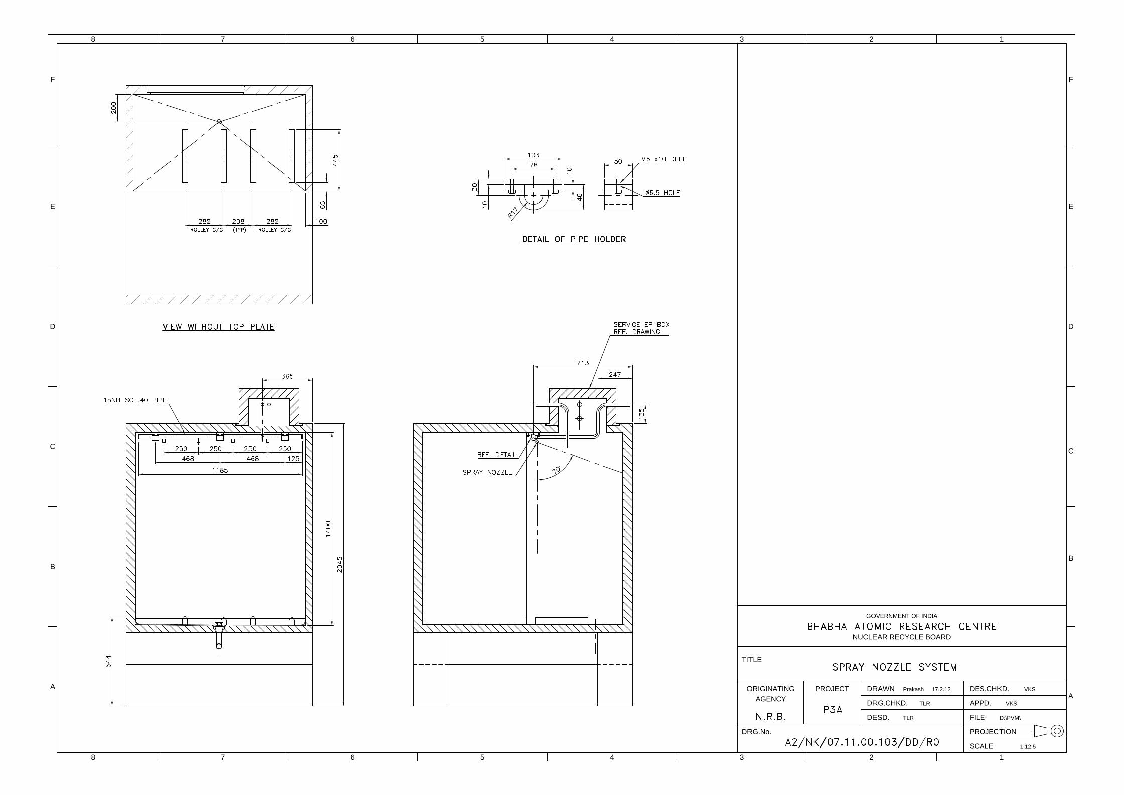
help in ventilation of the Enclosure Train during RMC parking, maintenance of pump modules. The remote module carrier is envisaged to be added in the RHMP Enclosure Trains for carrying out remote removal of the remote head modules, closing of the internal isolation doors & cartridge replacement. The width of the operating corridor may vary as per the design of the RMC. This will be conveyed to the vendor at the time of detailing. Further the vendor shall provide support pads to rails for RMC movement and supports for cabling inside the RMC operating corridor as per the requirement. This shall also accommodate a remote module carrier for performing remote maintenance on metering pumps. So necessary dimensional accuracies on all pump modules and their erection shall be carefully accomplished. Additional rails and fixtures for laying cables for operation of RMC shall also be in the scope of the vendor. This requirement shall be decided during its manufacturing. Metering pump circuit: Each metering pump remote head (FIM) shall have a suction line, a discharge line & a hydraulic line. The suction and discharge lines after entering the RHMP Enclosure Train shall be provided with bellow sealed valves (FIM). The suction line is connected to the remote operable strainer after the bellow sealed valve. The remote operable strainer out let is connected to the suction flange connector. The downstream side pipe of the suction flange connector shall be connected to the remote head (FIM) suction NRV. The discharge line starts from remote head discharge NRV. This is connected to the discharge flange connector (FIM). The upstream flange of the discharge flange connector shall be connected to the bellow sealed valve (FIM). The outlet of bellow sealed valve shall be laid up to the train top. Bellow sealed valves are pneumatically operated. There shall be a 15 N.B. SS 304L EP as indicated in the drawing for laying the pneumatic connection to the bellow sealed valve. The pneumatic connection is a 10N.B. SS tube. Provision shall be made on both the internal and external side of the train enclosure for sealing the 15 N.B. pipe after passing the pneumatic connection. Procedure for handling and welding of the Bellow sealed valves is given in the attached Appendix. The hydraulic line is connected to the drive head which shall be located on the platform above the RHMP Enclosure Trains. The drive head shall be installed on the platform with a SS tray below it. This tray shall be seal welded on all sides to contain the spilled hydraulic oil. The concrete platform is existing at some places in floor-2. MS platforms of an overall 3 meter length x 2.5 meter width shall be fabricated & erected at site for installing the drive heads. The platform shall be supported from the cell walls and the existing concrete platform columns. There shall not be any support from the floor and it shall be in the scope of the vendor. All SS pipes / tubes will be issued as FIM. Remote Head Pump Module: The remote head (FIM) shall be installed on a rolling stand which is called remote head module. The remote head module moves on two boxed rails. These rails also forms support stand for flange connector bracket. The suction, discharge & hydraulic flange connectors shall be mounted on flange connector bracket. The hydraulic line which is at the top of the remote head is connected with suitable elbow extension to another flange connector. This flange connector shall be housed on the same flange connector bracket. The flange connector bracket is fixed at the top to the internal top block of enclosure. An instrument wiring connector for rupture indicator instrument shall be provided. The connector and rupture indicator and wiring shall be FIM. The connector shall be housed in a TEFZEL hollow rod with taper groove for remote connecting of the connector when the pump module slides into the pump bay, maintenance bay etc. Fabrication installation & commissioning of this system is in the scope of the vendor. Flushing Arrangement: There shall be one no. each 15 NB N.B. sch. 40 SS 304L EP on EP box for flushing line inside all the compartments with spray nozzles. The spacing of the nozzles shall be 250 mm apart. Each compartment of the RHMP Enclosure
Page 5 of 107
Train shall have this fixed flushing arrangement. This is shown in the flushing arrangement drawing. In addition to this there shall be a line flushing arrangement. This flushing line shall be ¼” SS304L flexible pipe of 1.5 m length for flushing the internals of all the RHMP Enclosure Train compartments. Procurement, installation of these SS flushing nozzles & flexible hoses shall be in the scope of the vendor. There shall be a provision for hanging the flexible tube at appropriate location inside the train. Strainer bay: Remote operable strainers are installed on the suction side of the pumps. This is a pot type construction with remote operable top lid facility. The constructional drawing is provided along with the specs. M.O.C. shall be SS 304L. The cartridge shall have 60 MPI SS wire mesh with 240 micron opening. All the strainers in the strainer bays shall be installed in such a way so that the strainer actuating screw is positioned in exactly the same location in x, y, z, at all places. This is required for remote operation. Manufacture, testing. Demonstration and commissioning of these remote operable strainers shall also be in the scope of the vendor. The remote operable strainer is fixed to the partition walls of the compartments of the enclosure train. There shall be hangers mounted on the partition wall for hanging strainer cartridges & remote operable strainer top cover (press plate). Three extra strainer top lids for each RHMP Enclosure Train shall be supplied as spare. Three No. strainer top lids with flushing arrangement (flushing lids) for each RHMP Enclosure Train shall also be supplied for flushing purpose. Drain trays: The bottom of each compartment shall have 5 mm thick SS 304L .tray with proper slope for collecting the spilled liquids and completely drain the spilled contents to the drain line. The vendor shall conduct fill test for each tray and demonstrate that no liquid is left inside the tray once the drain line plug is uncovered. The drain nozzle for the tray shall be machined nozzle from SS 304L forged bar. The welding of the drain nozzle to the drain tray shall be 100% radiographed. Drain lines & headers: The RHMP Enclosure Train floor shall be lined with 5 mm thick SS304L plate this shall have drain lines which are laid below the RHMP Enclosure Train in shielded ducts. Approximate length of drain line ducts will be 200 thick - 10 meters, 100 thick – 10 meters & 63 mm thick 15 meters. These ducts shall be lined internally and externally with SS 304L sheet. The connection of the drain line to the cell walls shall be as indicated in the drawing. Maintenance bays: There shall be remote head maintenance bays in each RHMP Enclosure Train as indicated in the drawing. The pump modules maintenance is intended to be carried out in these bays. The pump module shall be pushed inside the maintenance bay on the rails laid on the turn table mounted on maintenance bay floor with the help of Remote module carrier / mini power manipulator. The mini power manipulator shall be designed for specific operational requirement. The pump module front plate holding the suction & discharge flanges shall be loosened from pump stand and slide 200 mm apart. There shall be a stand in front of the rails this shall have matching grooves for sliding the pump module front plate. The turn table shall have positional locking facility for matching the grooves and rails. Any deviation in this design for ease of functional requirement shall be approved by the designer. The remote head circumferential bolts shall be opened and the liquid head shall be separated for replacement of the diaphragm. Assembly shall be done in the reverse order. Suction & discharge NRVs also needs replacement. Unscrewing of the Allen screws of the NRVs and replacement of the NRVs is also envisaged to be carried out in the maintenance bay. Suitable tooling for these maintenance operations shall be supplied by the vendor. After overhauling of the remote head the same shall be shifted on the rails installed on the side in the maintenance bay. Here the remote head module suction discharge and hydraulic pipes shall be connected to the remote flange
Page 6 of 107
connectors installed at exactly same X,Y,Z, locations as installed in the pump bays with the help of RMC. There shall be a 9 N.B. sch. 40 SS 304L EP for applying hydraulic pressure to the remote head module for checking leaks. Each maintenance bay shall be provided with mini hydraulic pressure generating unit for applying hydraulic pressure. The pressure to be applied shall be a max. of 10 bar. The remote head module shall dock with these flange connectors for testing purpose. A 9N.B. Sch. 40 SS 304L EP shall be laid as shown in the drawing with ¼” SS304L flexible pipe. This pipe shall be connected to the suction flange connector flange. The discharge flange connector flange shall have a bleed & lock facility as shown in the drawing. There shall be a stand with rollers fixed to the side wall of the maintenance bay for transfer of the strainer transfer cask for transferring the used cartridge to the disposal cask. The details are given in the drawing. Each maintenance bay shall have cartridge transfer stand details of which are given in the drawing. There shall be a 9 N.B. sch. 40 SS 304L EP for flushing line inside the maintenance bay. This flushing line shall be ¼” SS304L flexible pipe of sufficient length for flushing the internal compartments. There shall a provision for hanging the flexible tube at appropriate location inside the maintenance bay. Wiring for rupture indicator instrument shall also be laid in the maintenance bay. A stationary internal cleaning facility apart from the flushing line shall also be provided for each compartment. This shall be a 15 N.B. sch. 40 SS 304L pipe fixed at the internal top of each compartment with spray nozzles at 250 mm pitch. This line shall be connected to the EP box line. Storage bays: There shall be remote head module storage bays in the RHMP Enclosure Train as indicated in the drawing. These storage bays are envisaged for module maintenance purpose. Metering pump remote head will be made available as FIM to the vendor for manufacturing the spare remote head modules. The storage bays houses spare remote head modules for replacement purpose. There shall be a 9 N.B. sch. 40 SS 304l EP for flushing line inside the storage bay. This flushing line shall be ¼” SS304L flexible pipe of sufficient length for flushing the internals of the maintenance bay. There shall a provision for hanging the flexible tube at appropriate location inside the maintenance bay. A stationary internal cleaning facility apart from the flushing line shall also be provided for each compartment. This shall be a 15 N.B. sch. 40 SS 304L pipe fixed at the internal top of each compartment with spray nozzles at 250 mm pitch. This line shall be connected to the EP box line. Remote Module Carrier operating gallery: The remote module carrier operating gallery shall be for the complete length of the enclosure train. One RMC will be installed in this gallery. The dimension of the gallery are only indicative, they may change as per the design of the remote module carrier. The RMC operating gallery shall be provided with cable supports and rails for movement of RMC. The details will be provided during the course of manufacture. Isolation doors shall be provided between maintenance bays, storage bays, RMC maintenance bays and RMC operating gallery. These doors shall be amenable for remote opening & closing by RMC. Cartridge storage bay: There shall be cartridge storage bays for storing the used strainers. All the equipment installed inside the RHMP Enclosure Train shall be hermitically sealed so to be compatible with the internal nitric acid environment. . Enclosure Attachments: The RHMP Enclosure Train shall have provision for laying 100 NB vent lines on top block, EP boxes for service EPs, Hydraulic line EP for connecting to drive head, shielded swing doors on front and rear face & RSWs on front face. There shall be service EP, boxes, Illumination arrangement, camera attachments on the top block. There shall be shielded blocks internally lined with SS 304L with side
Page 7 of 107
openings for introducing ventilation lines. All shielded boxes shall be internally lined with 3 thick SS304L sheet. Drive heads of metering pumps: The drive heads of the metering pumps shall be installed on the concrete platforms on the top of the RHMP Enclosure Trains at site. M.S. foundations shall be made as per the dimensions provided for installation of these drives heads. Concrete platforms for some portion of the RHMP Enclosure Train length are erected at site. Extension of platform as per the requirement for installing pump drive heads shall be in the scope of the vendor. SS trays shall be fabricated and installed below the drive heads to collect spilled oil as detailed in the drawing. The drive head shall be installed on the foundations which shall be made as per the drawings and site conditions. Enclosure Train: The RHMP Enclosure Train is a shielded enclosure for housing remote heads of metering pumps. The Train is made of mild steel with stainless steel 304L internal lining, installed approx. 1.6 meters away from cell wall. The RHMP Enclosure Train is to be installed on floor-2 north gallery of project P3-A. All walls of the Train is made of thick MS plates as given in the drawing for shielding purpose. The rear opening of the Train shall be closed with stainless steel SS304L sheets with soft gasketing (TEFZEL) and shall have an arrangement for easy to remove and fix back. These 3 mm thick SS plate covers shall form a leak tight fixture to the Enclosure Train rear face. The Enclosure Train shall have a drain tray with proper slope at the bottom to collect and drain the spilled liquid. The tray shall be fabricated from 5 mm thick SS 304L sheet. The tray shall not have any welding except for the corners and drain Nozzle. The tray shall have drain nozzle of 40 NB size. The drain attachment shall be fabricated as per drawing provided. The drain attachment shall be fabricated from SS 304L forged bar. The drain nozzles of the compartments shall be connected to the 40 N.B. SS 304L drain headers. Illuminating Arrangement & Camera Attachments: The top blocks of the Enclosure are provided with nozzles for service lines. The illumination inside the RHMP Enclosure Train shall be at least 500 Lux. T5 549 MM 4W LED Tubes LT-T5-4W-549 mm LED tubes of Lighting Orient Co, Ltd. make or equivalent shall be employed for illumination of RHMP Enclosure Trains. The tube diameter being 25 mm Sch. 20 SS 304L pipes shall be used for lining of the holes for housing LED tubes in top block. The LED tube insertion holes shall be made in the shielded top block as shown in the drawing. There shall be similar arrangement in the top block for installing cameras for internal viewing as detailed in the drawing. Train Ventilation: Rectangular cut outs for ventilation shall be provided on the top block. These cut outs shall have a groove on the top block and shall be fitted with shielded box with circular opening at the side with 4” N.B. Sch. 10 SS 304L pipe as detailed in the drawing or as per site conditions in consultation and approval of the EIC BARC. The internal of the cut out and the internal hallow portion of the shielded box shall be lined with 3 mm thick SS 304L plate. This grooved box shall sit in a groove of 5 m deep on the top block of the RHMP Enclosure Train at the designated location. Cut Out for Suction, Discharge & Hydraulic lines: There shall be a set of rectangular cut outs with identical construction as detailed above for introducing suction and discharge lines. The RHMP Enclosure Train top face at the place of cut out shall have a square groove as shown in the drawing. The grove top face shall also be lined with 3 mm thick SS 304L sheet. The groove square face shall have 6 mm thick lead sheet with internal cut out.
Page 8 of 107
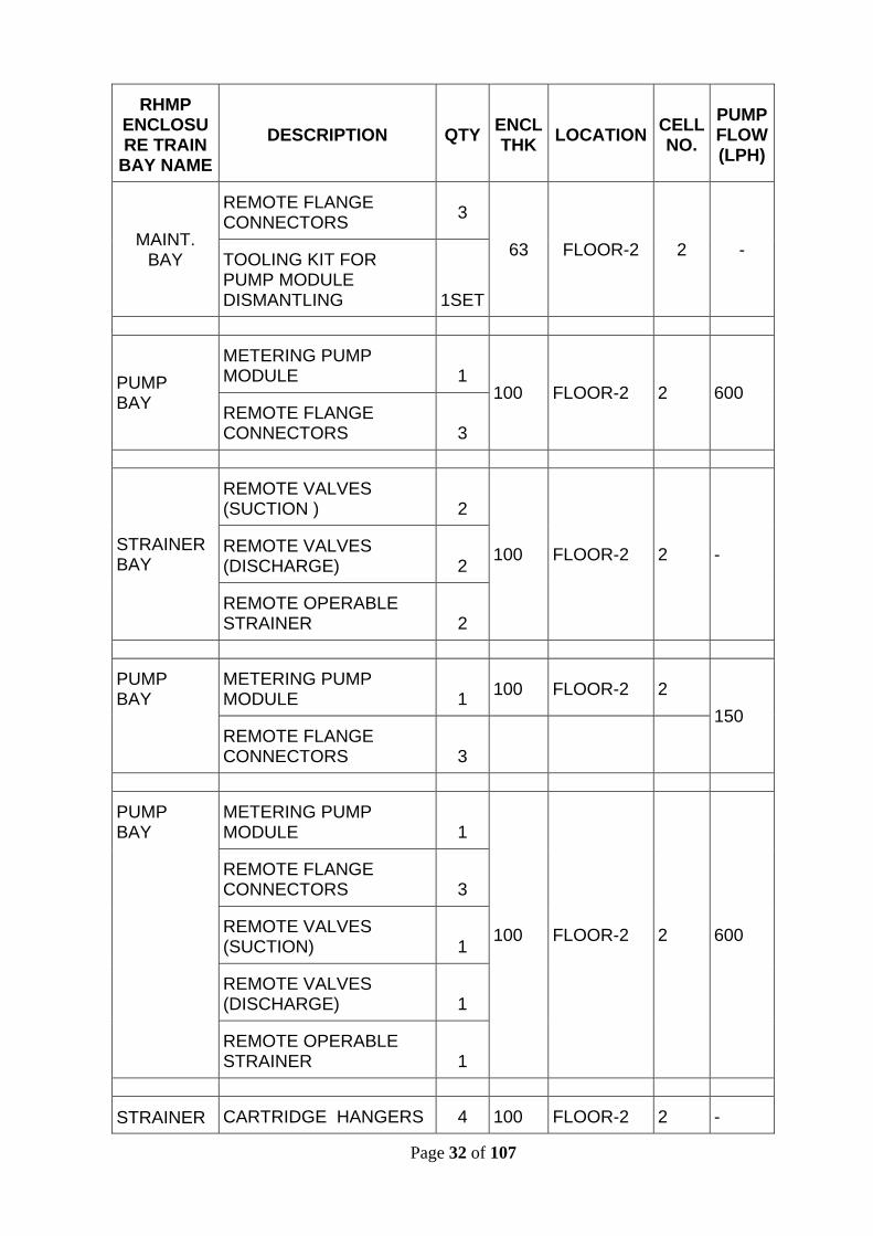
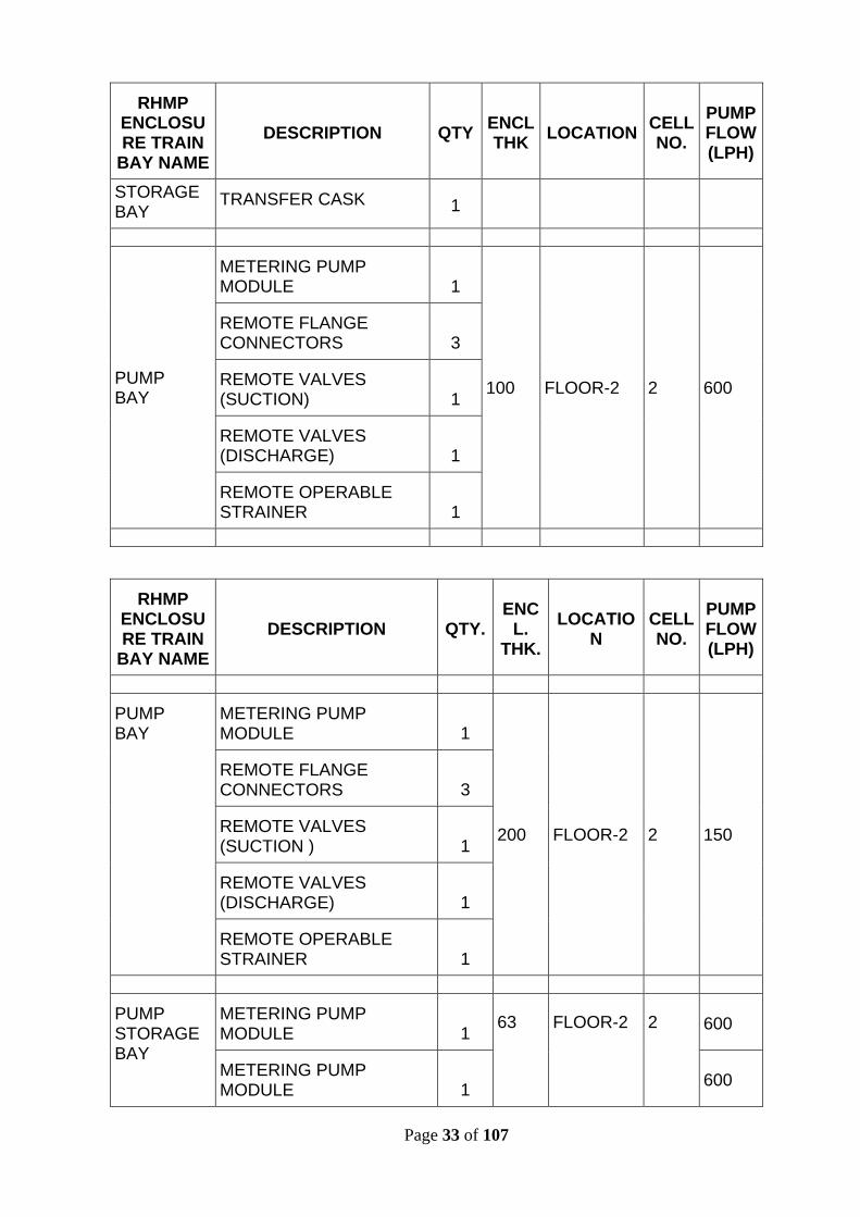
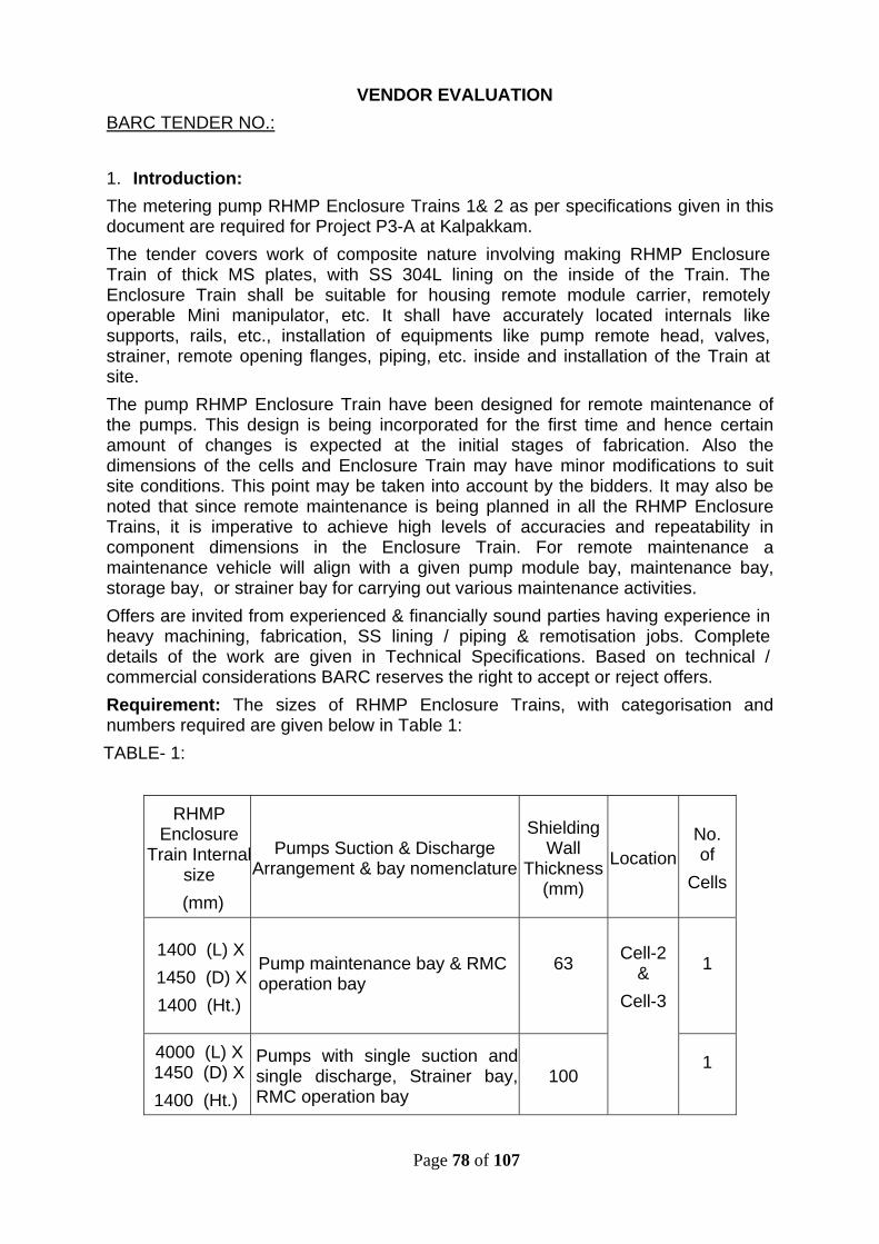
There shall be rectangular shielded box for hydraulic lines these shall also have same construction except for the hydraulic line. The hydraulic line shall emanate from side face of the rectangular box as given in the drawing. Instrument wiring connection for rupture indicator of RHMPs inside the Enclosure Train shall be in the scope of the vendor. This shall terminate at the top of the Train Enclosure with proper sealing. Viewing Windows: Provision for mounting lead viewing windows on the front wall of the Train at specified location shall be made. The viewing windows are given to the vendor as FIM at site. After complete erection of the RHMP Enclosure Train, viewing windows shall be installed on the front wall. Supply and fixing of the fasteners for mounting lead viewing windows shall be in the scope of the vendor. The cut out of the viewing Windows shall be lined with SS 304L 3 mm thick plate. The dimensions of the cut outs for installing lead viewing windows are given in the drawing; however the vendor shall confirm from the site the exact dimensions before fabrication of the cut outs in the RHMP Enclosure Train. Front Block Shielding Doors: Shielding doors shall be installed on the front door at specified locations on front wall of the RHMP Enclosure Train. Service EPs: Adequate compensating shielding shall be provided at places where EPs are penetrating the enclosure of the train wall. All service EPs shall penetrate through the EP box provided on the Enclosure Train top block. The drawings indicate internal dimensions of RHMP Enclosure Train. There are two types of pump and valve arrangements in this Train viz. single pump with single suction / single discharge, and two pumps with individual (one) suction / one discharge, each. This aspect has a bearing on the internal equipment and piping arrangement. The RHMP Enclosure Train has different shielding (wall) thickness. All support locations shall have at least 10 mm thick SS 304L pad plates embedded in the M.S. shielding. Table1 shows the approximate overall internal dimensions of the RHMP Enclosure Train to be installed in floor-2 A/G. The dimensions may vary as per site conditions. The internal dimensions of the RHMP Enclosure Train may vary as per the design of the RMC. This will have a bearing on the foundation frame dimensions also. The vendor shall keep this in mind while quoting. TABLE – 1: H OT CELL No. 2 DIMENSIONS
RHMP Enclosure
Train Internal Cell size
(mm)
Pumps Suction & Discharge Arrangement & bay nomenclature
Shielding Wall
Thickness (mm)
Location No. ofCells
1400 (L) X 1450 (D) X 1400 (Ht.)
Pump maintenance bay & RMC operation bay
63
1
4000 (L) X 1450 (D) X
1400 (Ht.)
Pumps with single suction and single discharge, Strainer bay, RMC operation bay
100
Cell-2 & Cell-3
1
Page 9 of 107
2035 (L) X 1450 (D) X 1400 (Ht.)
Pumps with single suction and single discharge. RMC operation bay 200
1
3955 (L) X 1450 (D) X 1400 (Ht.)
Pump storage bay, Pump bay & RMC operation bay. 63 1
1665 (L) X 885 (D) X 1400 (Ht.)
RMC maintenance bay in line with RMC operation bay 63 1
DETAILED DESCRIPTIONRHMP ENCLOSURE TRAINS Back Wall: The rear portion of the RHMP Enclosure Train of each compartment shall be open and shall be lined with 3 mm thick SS 304L plate. This face shall have embedded SS ring for holding soft TEFZEL/PTFE gasket. The rear opening shall be closed with 3 mm thick SS 304L cover plate. The closure of the plate shall be with sufficient cam type of levers as shown in the drawing for achieving leak tight joint. The rear side of the Train shall have hinged shielding doors in addition to the cover plate. The internal face of the doors shall be lined with 3 mm thick SS 304L plate. These hinged doors shall have locking arrangement for arresting door movement for closed position ad fully open position. The thickness of the hinged doors shall be as per the thickness of the RHMP Enclosure Train. The hinged doors shall be provided with bearing for ease of operation. Front Face: The front portion of the RHMP Enclosure Train of each compartment shall be open and shall be lined with 3 mm thick SS 304L plate. This face shall have embedded SS ring for holding soft TEFZEL/PTFE gasket. The front opening shall be closed with 3 mm thick SS 304L cover plate. The closure of the plate shall be with sufficient cam type of levers as shown in the drawing for achieving leak tight joint. The internal portion of the complete Train shall be lined with 3 mm thick SS 304L plate. The front face shall be closed with hinged doors. The sizes and constructional details of the same are given in drawings. The internal face of the door shall be lined with 3 mm thick SS 304L plate. The front hinged door shall have bearings for smooth operation. The top portion of front face of the Train shall have radiation shielding windows. These shielding windows shall be provided by BARC at site. Shifting of radiation shielding windows (RSWs) from stores to site location and installation shall be in the scope of the vendor. Supply and fixing of all fasteners required for fixing of RSWs shall also be in the scope of the vendor. The cut out sizes for installing the RSWs is given in the drawing. Any modifications such as grinding, fixing additional plates to fix the RSWs shall also be in the scope of the vendor. The RMC bay’s both faces shall be operable with hinged doors. This face shall have embedded SS ring for holding soft TEFZEL/PTFE gasket. The front opening shall be closed with 3 mm thick SS 304L cover plate. The closure of the plate shall be with sufficient cam type of levers as shown in the drawing for achieving leak tight joint. The internal portion of the complete Train shall be lined with 3 mm thick SS 304L plate. The front face of the Train shall be closed with hinged doors. The sizes and constructional details of the same are given in drawings. The internal face of the door shall be lined with 3 mm thick SS 304L plate. The front hinged door shall have bearings for smooth operation.
Page 10 of 107
Bottom: The RHMP Enclosure Train bottom shall have a drain tray formed from 5mm thick plate and shall have a skirting of 50 mm height on all sides. 40 N.B. Sch. 40 SS 304L Pipe shall be employed for drain purpose. The construction details of the drain line and the joining details are given in the drawing. Any welds on the tray shall be DP tested / radiographed / vacuum box tested, as the case may be. The fabrication procedure for the tray shall ensure minimal unrelieved cold working stresses. The drain shall have a sieve plate cover welded over it inside the drain nozzle attachment. The drain nozzle attachment shall be manufactured as per drawing. The drain nozzle attachment shall be fabricated from SS 304L forged rod. Liquid drain test with water shall be conducted for all the trays. Water shall be filled in the tray after plugging the drain nozzle. There shall be no water left out in the tray once the nozzle plug is opened. This shall be confirmed and demonstrated for all the RHMP Enclosure Trains. The bottom shielding thickness shall be suitably added on to the tray to compensate loss of shielding at the drain point & drain line. Enclosure side face linings shall be welded to the tray. The vertical joints shall be D.P. tested and vacuum box tested. The drain line from every compartment shall be connected to drain headers as detailed in the drawing. The drain header shall also be suitable shielded as shown in the drawing. This header shall in turn be connected to the lines running in the trench. The trench shall be provided with suitable shielding with stepped plugs to restrict streaming of radiation. The shielding plugs shall be lines with SS 304L plate from all sides for ease of decontamination. The Bottom face shall support railings, Support brackets for flange connectors, fixture plates, railing for pumps in pump bays, maintenance bays and storage bays. The bottom plate shall also support for railings for RMC in RMC operating bay, Overhaul bay & spare bay. All supports and brackets provided on the floor shall have cut outs at bottom such that there is no spilled liquid collection at corners. All spilled liquid shall flow towards drain smoothly. This shall be ensured for each compartment of the RHMP Enclosure Train during fabrication at various stages. Top Block: The top blocks of the RHMP Enclosure Trains are provided with nozzles for service lines. All the service lines shall penetrate the Enclosure top block at right angle. Stepped openings internally lined with SS for introducing lighting fixtures and cameras shall be provided in the top wall. All the shielded plugs shall have lifting arrangement with adequately sized eye bolts. Compensating shielding of 100 mm thick M.S. plate as shown in the drawing shall be welded at specified location on the top block. Supply installation of complete lighting fixture with bulbs & cameras for ready to plug in & use shall be in the scope of the supplier. Rectangular cut outs for ventilation shall be provided on the top block. These cut outs shall have a groove on the top block and shall be fitted with shielded box with circular opening at the side to accommodate 4” N.B. Sch. 10 SS 304L pipe at prescribed angle. The internal of the cut out and the internal hallow portion & the opening for accommodating 100 N.B. pipe of the shielded box shall also be lined with 3 mm thick SS 304L plate. Rectangular cut outs with internal lining for introducing suction and discharge lines shall be provided. The cut outs top face shall have a square groove as shown in the drawing. The grove top face shall also be lined with 3 mm thick SS 304L sheet. The groove square face shall have 6 mm thick lead sheet with internal cut out. There shall be rectangular shielded boxes for insertion of hydraulic line. This shall also have same construction except the hydraulic line shall emanate from side face of the rectangular box. The top wall of the RHMP Enclosure Train shall have EP box as shown in the drawing for services. All these EPs shall be located as shown in the drawing. Location of all these shall be as per drawings provided by the purchaser. The top block shall have a lining of SS 304 L plate of 3mm thickness on the inner face. The removable shielded plugs shall be provided with Tefzel gasketing to restrict any leakages.
Page 11 of 107
The internal of the top block shall support / house DSL with 110 V power supply for powering RMC in the groove/ covered box in RMC operating bay. The opening of the groove/ covered box shall be covered with flexible guard closure to restrict any internal environment coming in contact with bare power cord. The support for trailing cable shall also be from top block. The trailing cable shall be of acid resistant quality. Side Walls: The sidewalls shall provide support for the various internals like strainer opening mechanism, flange connectors, etc. as necessary. All internals of the side walls shall be lined with 3 mm thick SS 304L plate. Any screwing for the supports shall be done in SS 304L plugs embedded in side walls. The plugs shall be seal welded to the internal lining. All Allen screws shall be S.S. 316 material and shall be of same dimensions. Any fixing of supports shall be done initially with metal locking design then doweling and there after the supports any place shall be screwed to blocks. All these openings shall be closed by circular stepped plugs lined with S.S. with Allen screws fixed in counter sunk groves in place at the time of installation. SS lining of 3mm thickness, on all walls shall be welded to make a leak tight SS box. The integrity of the complete lining of the box shall be ensured by D.P. testing and vacuum box test at all possible places. Lining: The RHMP Enclosure Trains shall be lined with 3 mm thick S.S. 304L sheet on internal faces. Except for bottom block where the lining shall be from 5 mm thick SS 304L plate. Adequately thickness SS plates shall be embedded in the M.S. shielding and welded at support locations for taking the concerned load. The lining shall be seal welded to these support plates on all sides to maintain integrity of the lining. The inner surface of the Enclosure Train door and the front external surface shall also be lined with SS 304L plate. Module Design: The RHMP Enclosure Train shall be manufactured in small modules with bolted design for performance testing at vendor’s works. These modules shall be knocked down and transported to site. All such modules shall be assembled to make a train and installed again at site by bolting for demonstration of the functionality. After successful operations of remote gadgets of the RHMP Enclosure Train and full functionality test & clearance from the purchaser final welding of the complete Train at site shall be carried out by the vendor. The performance of the system as per the requirement given in the tender specifications shall be demonstrated to the purchaser on final completion of the installation at site. Internal Supports: It is planned to Automate / Remotise the maintenance activities of metering pump remote heads. The pump remote head shall have rails fixed to the floor for easy movement of remote head assembly with roller stand. The pump suction / discharge pipe flanges shall have remote opening connectors on them. These remote opening flange connectors shall be fixed and supported from the bottom & top walls of the RHMP Enclosure Train and shall be operable both from RMC operating bay & back door. The RMC will have remote opening tools to perform the task. For this purpose the flange connector shall have an opener extended suitable as detailed in the drawing. This extension shall be suitably supported on brackets of pump module. All the fixtures on brackets of pump module and the bushes for actuating rods shall have square stepped fixtures for restricting the rotation. The bushes for actuating rods shall have counter sunk stepped holes in addition to the square steps. All fixtures shall be fixed with counter sunk Allen screws. All such fixing screws shall be of identical size. All modules of similar type shall be exactly identical. The strainer shall be operable from RMC operating bay. The strainer body and operating mechanism shall be supported from the partition walls with S.S. 304L plate of suitable thickness. An extended opener similar to the flange connector shall be used for this purpose. The extended opener shall have supports from strainer operating mechanism face of have adequate reach for
Page 12 of 107
operation by opening mechanism installed on RMC. The supports required shall be in the form of rails, brackets, pipe sleeves, bearings etc. manufacture assembly installation and testing for smooth operation and leak tightness of all the joints on strainer, pump module shall also be in the scope of the vendor. The internals of the Enclosure Train including supports guides etc. shall have close tolerances and surface finish of the order of 0.4 μ to support the remote maintenance tools / gadgets. Close tolerances and locational accuracies shall be maintained for achieving reliability of repeated operations, similarity and interchangeability in the RHMP Enclosure Trains for remote gadgets. Pump Back plate (Remote Head Stand): The remote head of the pump is mounted on the stand with the help of four bolts. The pump stand shall be made from 20 mm thick SS 304L and this shall have rollers at the bottom. A support plate shall be mounted on the stand for housing bushes for suction, discharge & hydraulic lines of 25 N.B. & actuator rods for all the three connections. This support plate shall be of 20 mm thick which shall be fixed inside the groove of bottom block which in turn is mounted on the stand bottom plate as shown in the drawing. The top portion of the support plate shall be fixed with grooved plates 3 nos. along with remote head stand back plate. The fixing arrangement is sown in the drawing. The support plate along with remote head rolling stand and the remote head shall form pump module. Fixing of all blocks shall have metal groove locks and dowel pins in addition to the allen screws for fixing the plate. Each pump shall be fixed in such modules. For RHMP Enclosure Train No. 2 i.e. for cell-3 & cell-2 there shall be 7 Nos. remote head pump modules & 4 Nos. spare pump modules i.e. a total of 11 remote head pump modules. Every pump shall be provided with a remotely operable strainer as detailed in the drawing. There shall be 7 nos. remotely operable strainers. Manufacture, testing, supply & installation of these strainers shall be in the scope of the vendor. The remote head of metering pumps & flange connectors shall be supplied as FIM by BARC. GENERAL CONSTRUCTION DETAILS: The RHMP Enclosure Train is made up of following major parts; • PART (1) – Bottom block of the RHMP Enclosure Train lined with 5mm thick SS 304
L tray with skirting of 50 mm height on all sides. The tray drain nozzles shall protrude out of the bottom shielding. The drain nozzle of the tray shall be suitably extended by welding a 40 N.B. Sch. 40 SS 304L pipe. The drain shall be connected to 40 N.B. Sch. 40 SS 304L pipe header as given in the drawing. The drain header shall be suitably shielded.
• PART (2) – Side blocks of the RHMP Enclosure Train shall be lined with 3 thick SS 304 L plate.
• PART (3) – Internal Partitioning blocks of the RHMP Enclosure Train shall be lined with 3 thick SS 304 L plate. With additional pad plates of 10 mm thickness where ever supports for internal fixtures are made.
• PART (4) – Top shielding block of the RHMP Enclosure Train shall be lined internally with 3 mm thick SS 304 L plate. Where ever necessary additional pad plates of 20 mm thick shall be used for internal equipment supports. Any fasteners used for internal parts support shall have fixing thread inside 25 mm diameter SS 304L rod of sufficient length embedded in the shielding block with proper welding. This rod shall be seal welded to the internal SS lining. This block shall be provision for installing lighting fixtures, camera, suction and discharge lines, hydraulic lines, vents, Instrument lines for operation of remote valves. All these shall have stepped construction to restrict streaming of radiation through the openings. There shall not be any straight holes in the RHMP Enclosure Train.
Page 13 of 107
The top shielding block of the RHMP Enclosure Train shall also have provision of stepped holes with suitable plugs as shown in the drawing for maintenance purpose of power manipulator & RMC electrical consoles. All plugs shall have suitable eye bolts for lifting arrangement of the shielding plugs. Each shielding plug shall be suitably sized and proper lifting arrangement at all locations shall also be installed at site.
• PART-5 – Front block of the RHMP Enclosure Train shall be provided with radiation shielding windows at the upper portion and shielding doors at the lower elevation with suitable thickness. All the internal cutouts & front face shall be lined with SS 304L sheet. Window opening for RSW were given in the drawing. Installation of the RSWs at site shall be in the scope of the vendor. All fasteners required for fixing the RSWs and any alterations in the cutouts and shifting of RSWs from stores at the site to the location and installation shall also be in the scope of the vendor. The front openings of the RHMP Enclosure Train shall have hinged shielded doors. The shielding doors shall have suitable bearings at the hinges as per the weight of the door panels, for smooth operation. Shielding doors shall be lined with 3 mm thick SS 304L lining. The doors shall be fixed by means of hinged brackets. The total weight of the door shall be taken by the bottom-hinged brackets, which shall be provided with taper roller bearings. The top hinges shall be provided with deep groove ball bearings. The bottom door bracket of the shielding door shall sit on the thrust (taper roller) bearing of the bottom hinges and a clearance of 5 mm shall be given between the top door bracket and the bearing retainer of the top hinges. The wall brackets shall be secured to the wall plates by means of bolts. The wall plates shall be welded to the compensating strip, which in turn is welded to the RHMP Enclosure Train front block as shown in the drawing. The doors shall be in two halves for all RHMP Enclosure Trains. The doors shall have locking arrangement with cam type hinges mounted on the front face so that the doors remain intact when closed. The front openings of the RHMP Enclosure Train shall be closed with stainless steel SS304L sheets with soft gasketing and shall have an arrangement for easy to removal and fixing back. These 3 mm thick SS plate covers shall form a leak tight fixture to the RHMP Enclosure Train front face. There shall be handling provision for these SS plate covers and in addition the plate covers shall be hinged in the front face cut out.
• PART (6) – Rear Block: The rear openings of the RHMP Enclosure Train shall have hinged shielded doors. The shielding doors shall have suitable bearings at the hinges as per the weight of the door panels, for smooth operation. Shielding doors shall be lined with 3 mm thick SS 304L lining. The doors shall be fixed by means of hinged brackets. The total weight of the door shall be taken by the bottom-hinged brackets, which shall be provided with taper roller bearings. The top hinges shall be provided with deep groove ball bearings. The bottom door bracket of the shielding door shall sit on the thrust (taper roller) bearing of the bottom hinges and a clearance of 5 mm shall be given between the top door bracket and the bearing retainer of the top hinges. The wall brackets shall be secured to the wall plates by means of bolts. The wall plates shall be welded to the compensating strip, which in turn is welded to the Enclosure Train rear block as shown in the drawing. The doors shall be in two halves for the Train or as detailed in the drawing. These hinged doors shall have locking arrangement in closed position and in fully open position. The doors shall have locking arrangement with cam type hinges mounted on the rear face so that the doors remain intact when closed. The front openings of the Enclosure Train shall be closed with stainless steel SS304L sheets with soft gasketing and shall have an arrangement for easy to removal and fixing back. These 3 mm thick SS plate covers shall form a leak tight fixture to the RHMP
Page 14 of 107
Enclosure Train rear face. There shall be handling provision for these SS plate covers and in addition the plate covers shall be hinged in the front face cut out. Note: All blocks for the construction of the RHMP Enclosure Trains & shielded ducts shall have stepped construction with internal side 2/3RD of the block thickness and outer side 1/3Rd of the block thickness to avoid radiation streaming.
• PART (7) – MS split –plug with SS lining as shown in the drawing.
• PART (8) – 5 mm thick SS 304 L drain tray as shown in the drawing.
• PART (9) – ISWB 300 Support Structure for the RHMP Enclosure Train with
additional
Flanges lined with 3 mm thick SS 304L plate.
• PART (10) – SS 304 L service lines
• PART (11) – Cartridge transfer cask
• PART (12) – Cartridge disposal cask.
SHIELDED CASK FOR CARTRIDGE TRANSFER INTRODUCTION: This specification covers the requirement of Fabrication, Testing & Supply of ‘cartridge cartridge transfer cask. GENERAL DESCRIPTION: The tendered product is intended for transfer of strainer cartridges. The shielded cask basically a Lead filled hollow cylinder lined with stainless steel. The internal pipe shall be of 100 N.B. and the external pipe shall be of 250 N.B. pipe. The lead filled portion shall be tested for any blow holes or cavities and found any shall be corrected. The overall height of the cask shall be 290 mm. A 10 mm thick swing gate one each on top and bottom of the hollow cylinder is provided for preferential opening & closing of the cask internal for receipt and disposal of the cartridge. The swing gates shall have free movement. These swing gates are hinged at SS pins part no. 9. Spring loaded closing arrangement part no.7 shall be provided for bottom and top swing gates to enable forced opening & auto closing of both these gates. Four nos. heavy duty stainless steel wheels shall be provided for the bottom of the cask base plate for movement of shielded cask. A cup made of plastic of 1 mm wall thickness 90 mm OD & 145 mm height shall be placed inside the cask for receipt of cartridge. All parts shall be of machined construction. The cask after manufacture shall be pickled and passivated. The internal and external surfaces shall have buffed finish. All sharp corners shall be rounded off to at least 5R. CONSTRUCTION DETAILS OF TRANSFER CASK CASK BODY: Cask body is manufactured from SS 304L 250 N.B. pipe as outer body & the internal hollow shall be made from 100 N.B. pipe. Cask body is a hollow cylinder with external diameter of 273 mm and internal diameter of 90 mm. The middle internal hollow portion of cask shall be filled with lead. The top & bottom shielding disks are of 60 mm thick with central opening as shown in the drawing. The top and bottom plates are welded to the annular pipe. BOTTOM SWING PLATE & TOP SWING PLATE: The bottom & top swing plates are of SS 304L. There will be an arced disc attached to these plates as shown in the drawing. Each plate shall have 9 mm dia. holes two nos. as shown in the drawing. One is for the pivot and the other for holding spring for auto closing.
Page 15 of 107
PIVOT PINS: There shall be two pivot pins. Pivot pins are M10 bolts of 65 mm length. BASE PLATE: Base plate shall be 400mm X 400mm X 20 mm thick SS 304L plate. The cask body is welded to the base plate. There shall be one hook of 10 dia. rod at the front. The base plate shall be mounted on four SS wheels. CUP: Cup shall be of plastic and shall be of 145 mm length with 90 mm O.D. the thickness of this plastic cup shall be 1 mm. The cup is used for disposal of used cartridges. The cup shall be closed from the bottom. The cup shall have a slot of 8 mm width and 16 mm length as shown in the drawing. The vendor shall supply 50 cups along with each cask (Internal Transfer casks). In all a total of 300 cups shall be supplied along with internal transfer casks. SCOPE: Detailed engineering, preparation of drawings, machining, fabrication, assembly and testing of cartridge transfer casks shall be in the scope. Procurement of material, inspection, testing, packaging & supply shall be in the scope of the vendor. Mechanical & chemical test certificates of the material to be procured shall be submitted to the indentor for approval before purchase. Material shall be tested as per ASTM practice A & C and the corrosion rate of the material shall not be more than 18 mpy. The certification of material shall also be in the scope of vendor. Material approved by the indentor for procurement shall only be employed for fabrication. Transfer of markings shall be done in the presence of indentor and all such records shall be maintained by the vendor. Fabrication, assembly & testing shall conform to the approved drawings and specifications laid down by the indentor. REFERENCE DRAWINGS: The purchaser shall furnish basic design drawings/ sketches. It is in the scope of the vendor to prepare detailed design & engineering drawings. These drawings shall be complete with all details of machining including tolerances & finishes. The reference drawings for this purpose are given below:
Sr. No. TITLE Drawing No.
1. MULTI CARTRIDGE DISPOSAL CASK A2/NK.07.11.00.74/DD/R0
2. CARTRIDGE TRANSFER CASK FOR ENCLSOURE TRAINS A2/NK.07.11.00.75/DD/R0
The supplier shall get the design & engineering drawings approved from the purchaser before commencement of the job. Time required for submission of drawings shall be indicated separately. The supplier may incorporate changes or modifications as deemed advisable without affecting the functional requirements. Such changes shall be intimated to the purchaser and written approval for the same shall be taken before starting the job. The supplier shall be responsible and bear the cost of any alteration of works due to any errors or omissions in the drawings or other particulars supplied by him, whether such drawings or particulars have been approved by the purchaser or not. Engineering drawings shall be submitted and obtain the approval of the same before manufacture of the cask. MACHINING PROCEDURE & QA / QC PLAN: All plates shall be machined to true dimensions. The cask of fabrication shall be machined on internal and external surfaces. The finished product shall have buffed finish. All welding marks shall be removed by K2 paste before machining. The vendor shall submit detailed manufacturing & assembly flow sheets for all components and QA /QC plans for approval.
Page 16 of 107
MATERIAL PROCUREMENT: The vendor shall procure all materials and bought out components as mentioned in the specification and drawings. The vendor shall ensure the compliance of all bought out materials to standards and quality stipulated in the specification. The materials shall be procured from reputed manufacturer’s / AUTHORISED dealers with complete credentials of the genuinity of the item. Relevant QA plans for bought out items shall be followed and testing shall be done in consultation with the purchaser. Test reports and QA documents for these items shall be submitted to the purchaser. The material shall comply with relevant ASTM standard. Technical details of the bought out materials shall be furnished to the purchaser for evaluation and granting permission for procurement. Test certificates for chemical composition and mechanical properties of all materials used shall be submitted for approval. The quality of SS material shall be validated by a Govt. approved material testing laboratory at vendor’s cost for chemical composition, mechanical properties and corrosion resistance as applicable. Corrosion test as per ASTM A-262 Practice A & C shall be conduct for stainless steel pipes, plates & forged rods. The average overall corrosion rate during the five period cycle shall not exceed 18 MPY. Use of equivalent material shall not be preferred, in-case use of equivalent material is unavoidable, the same shall be done with prior written permission from the purchaser. DIMENSIONAL INSPECTION: The vendor shall comply with the requirements of the components conforming to required shape, thickness and dimension. Dimensional inspections are necessary during and after manufacture, and shall be performed to ensure that the completed portion of the manufactured item conforms to the design drawings. Requirement: There shall be two casks for each RHMP Enclosure Train. In all there shall be six (6 nos.) cartridge transfer casks. ACCEPTANCE CRITERIA: All the flange connectors shall be tested for acceptance as per above approved design and shall be considered acceptable if it meets the following: a) Dimensional accuracies as per drawings. b) Free & smooth movement of the cartridge transfer cask on rails. c) Free movement of top and bottom swing plates. d) Free insertion and disposal of plastic cup along with cartridge. e) Buffed internal and external surface finish of the complete unit.
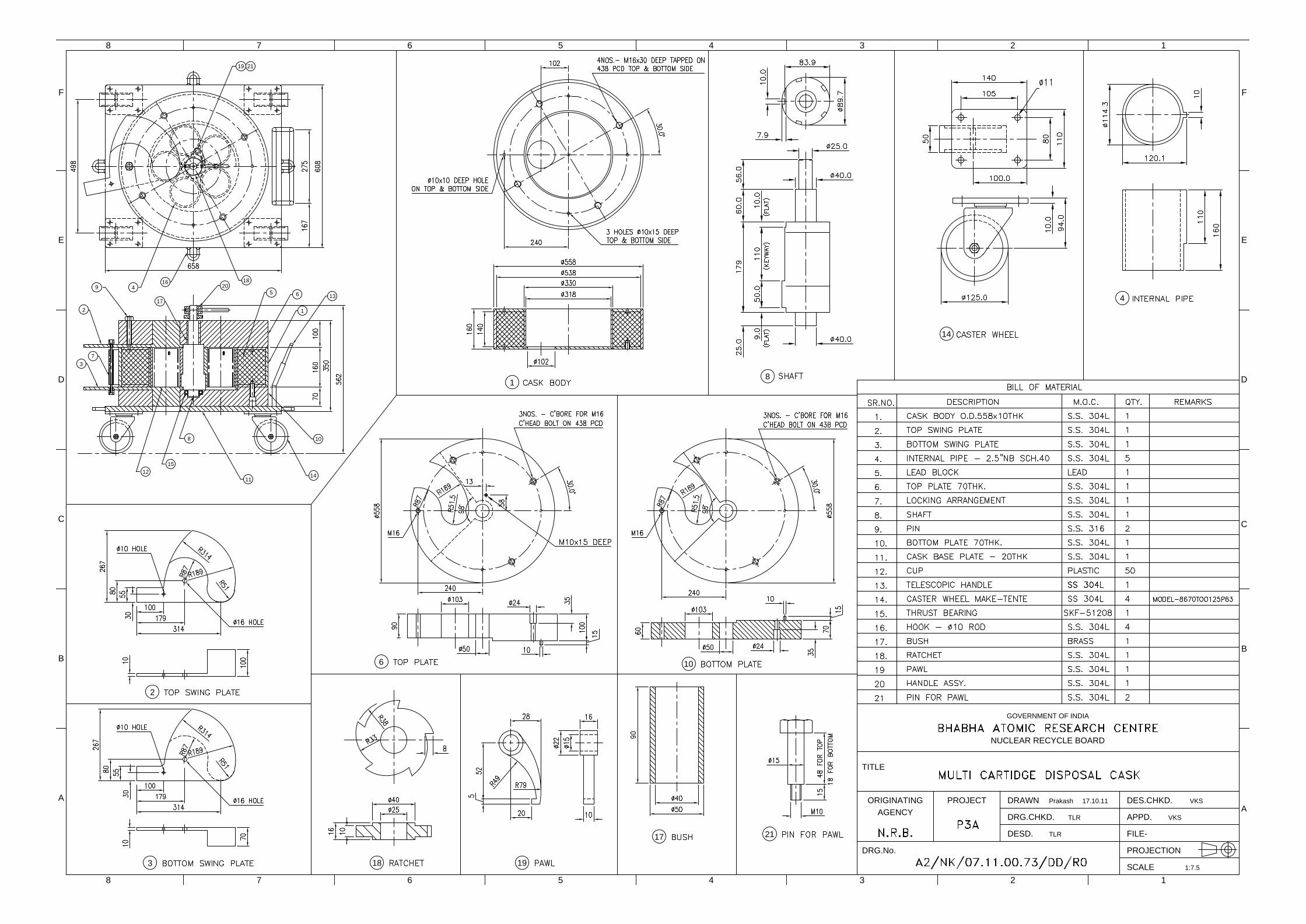
SHIELDED CASK FOR MULTI CARTRIDGE DISPOSAL INTRODUCTION: This specification covers the requirement of Fabrication, Testing & Supply of ‘cartridge cartridge disposal cask. GENERAL DESCRIPTION: The tendered product is intended for disposal of strainer cartridges. Fabrication, machining & supply of six disposal casks shall be in the scope of the vendor. Five cartridges at a time can be disposed by using this cask. The shielded cask basically a Lead filled hollow cylinder lined with stainless steel. There shall be five receptors at a radius of 102mm for receiving cartridges. The internal receptor pipe shall be of 100 N.B. and the external cask O.D. shall be of 558mm O.D. of 10 m thick plate. The lead filled portion shall be tested for any blow holes or cavities and found any shall be corrected. The overall height of the cask shall be 290 mm. A swing gate one each on top and bottom of the hollow cylinder is provided for preferential opening & closing of the cask internal for receipt and disposal of the cartridge. The swing gates shall have free movement. These swing gates are hinged at
Page 17 of 107
SS pins part no. 9. Locking arrangement part no.7 shall be provided for bottom and top swing gates to enable preferential opening & locking of any one these gates and at times both together and locking both the gates while in transfer. Four nos. heavy duty stainless steel castor wheels shall be provided for the bottom of the cask base plate for movement of shielded cask. The caster wheels shall be TENTE make of model 8670TOO125P63, EAN 4031582313437, Swivel castor, housing made of Stainless Steel, double ball bearing swivel head, protected, reinforced and heat-treated ball covers, riveted king pin, wheel axle with nut. Wheel centre made of Polyamide, heavy duty, plain bearing, plate fitting or equivalent. The details of caster wheels are attached in annexure. The base plate shall have a telescopic handle for moving the cask trolley. Two hooks made from 15 mm dia. SS rod with swivel facility shall be attached to the cask base plate. Four nos. heavy duty stainless steel castor wheels of 700 Kg capacity shall be provided for the bottom of the cask base plate for movement of shielded cask. A telescopic handle made out of SS shall be attached to the cask base plate for dragging the shielded cask A cup made of plastic of 1 mm wall thickness 90 mm OD & 145 mm height shall be placed inside the cask for receipt of cartridge. All parts shall be of machined construction. The cask after manufacture shall be pickled and passivated. The internal and external surfaces shall have buffed finish. All sharp corners shall be rounded off to at least 5R. CONSTRUCTION DETAILS OF DISPOSAL CASK CASK BODY: Cask body is manufactured from 558 mm O.D. of 10mm thick plate as outer body & the internal cartridge receptors shall be made from 100 N.B. Sch. 40 SS 304L pipe. There shall be five receptors attached to the central shaft of 80 mm dia. A mechanical pin push type arrangement as shown in the drawing shall be provided for indicating the filled receptor. The central shaft shall have a thrust bearing SKF 51208 at the bottom and the top portion shall have bush bearing. Cask body is a hollow cylinder with external diameter of 558 mm and internal diameter of 318 mm. The middle internal hollow portion of cask shall be filled with lead. The top & bottom shielding disks are of 60 mm thick filled with lead with central opening as shown in the drawing. The top and bottom shielded disks fixed to the annular pipe. BOTTOM SWING PLATE & TOP SWING PLATE: The bottom & top swing plates are of SS 304L and are 100 mm thick. There will be an arced disc attached to these plates as shown in the drawing. Each plate shall have 9 mm dia. holes two nos. as shown in the drawing. One is for the pivot and the other for locking. PIVOT PINS: There shall be two pivot pins. Pivot pins are M10 bolts of 65 mm length. BASE PLATE: Base plate shall be 608mm X 658mm X 30 mm thick SS 304L plate. The cask body is fixed to the base plate. There shall be one hook of 10 dia. rod at the front. The base plate shall be mounted on four castor wheels. CUP: Cup shall be of plastic and shall be of 145 mm length with 90 mm O.D. the thickness of this plastic cup shall be 1 mm. The cup is used for disposal of used cartridges. The cup shall be closed from the bottom. The cup shall have a slot of 8 mm width and 16 mm length as shown in the drawing. The vendor shall supply 50 cups along with each cask (Disposal cask). In all there shall be 300 cups. SCOPE: Detailed engineering, preparation of drawings, machining, fabrication, assembly and testing of cartridge disposal casks shall be in the scope. Procurement of material, inspection, testing, packaging & supply shall be in the scope of the vendor. Mechanical & chemical test certificates of the material to be procured shall be submitted to the indentor for approval before purchase. Material shall be tested as per ASTM practice A & C and the corrosion rate of the material shall not be more than 18
Page 18 of 107
MPY. The certification of material shall also be in the scope of vendor. Material approved by the indentor for procurement shall only be employed for fabrication. Transfer of markings shall be done in the presence of indentor and all such records shall be maintained by the vendor. Fabrication, assembly & testing shall conform to the approved drawings and specifications laid down by the indentor. REFERENCE DRAWINGS: The purchaser shall furnish basic design drawings/ sketches. It is in the scope of the vendor to prepare detailed design & engineering drawings. These drawings shall be complete with all details of machining including tolerances & finishes. The reference drawings for this purpose are given below:
Sl. No. TITLE Drawing No.
1. MULTI CARTRIDGE DISPOSAL CASK A2/NK.07.11.00.74/DD/R0
2. CARTRIDGE TRANSFER CASK FOR ENCLSOURE TRAINS A2/NK.07.11.00.75/DD/R0
The supplier shall get the design & engineering drawings approved from the purchaser before commencement of the job. Time required for submission of drawings shall be indicated separately. The supplier may incorporate changes or modifications as deemed advisable without affecting the functional requirements. Such changes shall be intimated to the purchaser and written approval for the same shall be taken before starting the job. The supplier shall be responsible and bear the cost of any alteration of works due to any errors or omissions in the drawings or other particulars supplied by him, whether such drawings or particulars have been approved by the purchaser or not. Engineering drawings shall be submitted and obtain the approval of the same before manufacture of the cask. MACHINING PROCEDURE & QA / QC PLAN: All plates shall be machined to true dimensions. The cask of fabrication shall be machined on lathe on internal and external surfaces. The finished product shall have buffed finish. All welding marks shall be removed by K2 paste before machining. The vendor shall submit detailed manufacturing & assembly flow sheets for all components and QA /QC plans for approval. MATERIAL PROCUREMENT: The vendor shall procure all materials and bought out components as mentioned in the specification and drawings. The vendor shall ensure the compliance of all bought out materials to standards and quality stipulated in the specification. The materials shall be procured from reputed manufacturer’s / AUTHORISED dealers with complete credentials of the genuinity of the item. Relevant QA plans for bought out items shall be followed and testing shall be done in consultation with the purchaser. Test reports and QA documents for these items shall be submitted to the purchaser. The material shall comply with relevant ASTM standard. Technical details of the bought out materials shall be furnished to the purchaser for evaluation and granting permission for procurement. Test certificates for chemical composition and mechanical properties of all materials used shall be submitted for approval. The quality of SS material shall be validated by a Govt. approved material testing laboratory at vendor’s cost for chemical composition, mechanical properties and corrosion resistance as applicable. Corrosion test as per ASTM A-262 Practice A & C shall be conduct for stainless steel pipes, plates & forged rods. The average overall corrosion rate during the five period cycle shall not exceed 18 MPY.
Page 19 of 107
Use of equivalent material shall not be preferred, in-case use of equivalent material is unavoidable, the same shall be done with prior written permission from the purchaser. DIMENSIONAL INSPECTION: The vendor shall comply with the requirements of the components conforming to required shape, thickness and dimension. Dimensional inspections are necessary during and after manufacture, and shall be performed to ensure that the completed portion of the manufactured item conforms to the design drawings. Requirement: There shall be two casks for each RHMP Enclosure Train. In all there shall be six (6 nos.) cartridge disposal casks. ACCEPTANCE CRITERIA: All the flange connectors shall be tested for acceptance as per above approved design and shall be considered acceptable if it meets the following: f) Dimensional accuracies as per drawings. g) Free & smooth movement of the cartridge disposal cask on rails. h) Free movement of top and bottom swing plates. i) Free insertion and disposal of plastic cup along with cartridge. j) Free & smooth operation of the cask trolley. k) Free & smooth movement of the mechanical arrangement for indication of filled
receptor l) Buffed internal and external surface finish of the complete unit. Requirement: There shall be one single cartridge transfer cask and two multicratridge disposal casks for RHMP Enclosure Train. INSTALLATION AT SITE: The back wall of the RHMP Enclosure Train shall be 20mm MS plate lined with 3 mm thick SS 304L plate from inside, having insertion holes for pipes to be inserted as per the drawings provided. Pipes embedded in walls at the site shall match these insertion holes. The supplier shall counter check the actual dimensions of the pipe EPs at site before installation. After welding the back face of the Enclosure Train to the wall EP, the service pipes & ventilation pipes protruding inside the Train through the insertion holes on back plate shall be seal welded with 3 mm thick pad plate (SS 304L) on to the S.S. lining of the Enclosure Train. The supply and welding of the 3 mm thick pad plate (SS 304L) shall be in the scope of the vendor This welding shall be DP tested and the service pipe EPs shall be hydraulic / pneumatic tested in the presence of site engineers. This testing and repairs if any shall also be in the scope of the vendor. All tests carried out shall be well documented and such test documents shall form part of supply. The drain pipe nozzle of the tray shall be welded in position to the pipe E.P. on the wall with suitable elbows and connecting pipe lengths. These welds shall be radiographed. After installation of the RHMP Enclosure Train and connecting the RHMP Enclosure Train drain line to the drain EP, the drain line shall be provided with adequate shielding by building a box type structure below and around it with MS plates / blocks internally lined with 3 thick SS304L plate. After installation of a RHMP Enclosure Train, all internals like, pump, piping with elbows (miter bends are not acceptable) and accessories, valves with air supply piping, remote operable strainers with supports, pipe supports, rails/ p[ump foundation supports, & remote opening devices for strainer shall be installed inside the RHMP Enclosure Train. The connection of the service lines to the nozzles provided on the RHMP Enclosure Train shall be in the scope of the supplier. The installation shall be checked for functioning by the purchaser. The installation of the RHMP Enclosure Train shall ensure that the internal bottom face of the train shall be horizontal.
Page 20 of 107
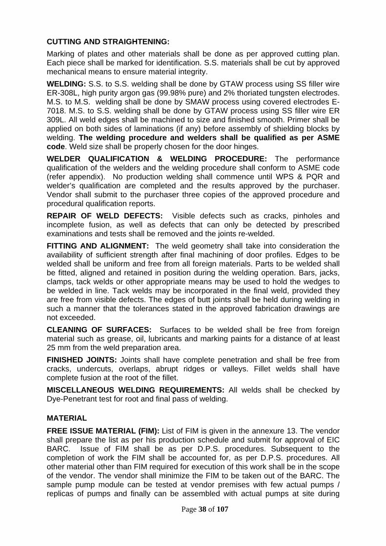
FABRICATION / MACHINING REQUIREMENTS: The vendor shall have appropriate machining and fabrication facilities required for welded fabrication of heavy Mild Steel shielding blocks and Stainless steel components/ mechanisms. The machines shall conform to the highest grade and have current calibration and test reports. The machines shall be capable of machining of heavy and large sized blocks and assembled RHMP Enclosure Trains. The vendor shall have the facility for automated oxy-acetylene gas cutting of thick mild steel plates to accurate size and edges. Note: All blocks for the construction of the RHMP Enclosure Trains & shielded ducts shall have stepped construction with internal side 2/3RD of the block thickness and outer side 1/3Rd of the block thickness to avoid radiation streaming. The vendor’s shop shall be equipped for welding of heavy MS plates apart from welding and fabrication of Stainless steel equipment. The shop shall have adequate handling facilities like EOT cranes etc. The vendor shall have testing and measuring instruments with latest calibration certificates. All the internals of the RHMP Enclosure Train like, lining, supports, bottom tray, etc. shall have a smooth finish to enable easy decontamination. The vendor shall submit detailed fabrication process plan indicating process, machines used, tolerances and valid current calibration certificates for the machines being employed for this job. The vendor shall also submit all welding process details, assembly sequence of the RHMP Enclosure Trains, inter-stage quality control and inspection checks. The vendor shall have all manufacturing facilities in-house and at one place. Installation and commissioning of all RHMP Enclosure Trains will be in the scope of the vendor. However the position of suction and discharge pipe insertion holes shall be confirmed from site before fabrication of all RHMP Enclosure Trains. The vendor shall submit a detailed installation plan. The vendor shall submit a comprehensive offer covering the entire requirement, supply, and installation and commissioning. Part offers will not be entertained. Supply of required nos. of hold fasteners and fixing shall be in the scope of the vendor. The vendor shall initially fabricate, machine & assemble one sample piece of the ordered item, which will be subjected to thorough inspection, testing & approval by the purchaser. WORKMANSHIP: Workmanship shall be in accordance with the best shop practices and standards as existing in engineering industry. The assemblies shall confirm to all dimensional, geometrical and quality requirements for ensuring sustained trouble free operation of system. Repeatability in the dimensions and tolerances for all RHMP Enclosure Train assemblies shall be ensured. CUTTING AND STRAIGHTENING: Marking of plates and other materials shall be done as per approved cutting plan. Each piece shall be marked for identification. S.S. materials shall be cut by approved mechanical means to ensure material integrity. WELDING: S.S. to S.S. welding shall be done by GTAW process using SS filler wire ER-308L, high purity argon gas (99.98% pure) and 2% thoriated tungsten electrodes. M.S. to M.S. welding shall be done by SMAW process using covered electrodes E-7018. M.S. to S.S. welding shall be done by GTAW process using SS filler wire ER 309L. All weld edges shall be machined to size and finished smooth. Primer shall be applied on both sides of laminations (if any) before assembly of shielding blocks by
Page 21 of 107
welding. The welding procedure and welders shall be qualified as per ASME code. Weld size shall be properly chosen for the door hinges. WELDER QUALIFICATION & WELDING PROCEDURE: The performance qualification of the welders and the welding procedure shall conform to ASME code (refer appendix). No production welding shall commence until WPS & PQR and welder’s qualification are completed and the results approved by the purchaser. Vendor shall submit to the purchaser three copies of the approved procedure and procedural qualification reports. REPAIR OF WELD DEFECTS: Visible defects such as cracks, pinholes and incomplete fusion, as well as defects that can only be detected by prescribed examinations and tests shall be removed and the joints re-welded. FITTING AND ALIGNMENT: The weld geometry shall take into consideration the availability of sufficient strength after final machining of door profiles. Edges to be welded shall be uniform and free from all foreign materials. Parts to be welded shall be fitted, aligned and retained in position during the welding operation. Bars, jacks, clamps, tack welds or other appropriate means may be used to hold the wedges to be welded in line. Tack welds may be incorporated in the final weld, provided they are free from visible defects. The edges of butt joints shall be held during welding in such a manner that the tolerances stated in the approved fabrication drawings are not exceeded. CLEANING OF SURFACES: All surfaces to be welded shall be cleaned free from foreign material such as grease, oil, lubricants and marking paints for a distance of at least 25 mm from the weld preparation area. FINISHED JOINTS: Joints shall have complete penetration and shall be free from cracks, undercuts, overlaps, abrupt ridges or valleys. Fillet welds shall have complete fusion at the root of the fillet. PIPE FITTINGS: SS 304L Butt welded reducers, Elbows & Tees shall be as per ANSI B 16.9 for connecting the suction / discharge lines and supply and installation of these shall be in the scope of the supplier. The supplier shall submit all relevant test certificates and documents for fabrication and supply of reducers. All the SS 304L material procured by the vendor shall have IGC test certificate as per ASTM A 262 Practice A & C. The average overall corrosion rate for the five test period cycle shall not exceed 18 MPY. A variation in the quantities given below to the extent of about 10-20% may be expected. Any extra cost for this variation shall be in the scope of the vendor. No extra payment shall be made by the purchaser for this purpose. The piping from service nozzles located in the top block of the RHMP Enclosure Train to the various locations inside the RHMP Enclosure Train shall also be in the scope of vendor. This includes water connection for flushing of RHMP Enclosure Train and airline for actuation of the valves. All this piping shall be done using SS 304L pipes. MISCELLANEOUS WELDING REQUIREMENTS: All welds shall be checked by Dye-Penetrant test for root and final pass of welding.
MATERIAL FREE ISSUE MATERIAL (FIM): List of FIM is given in the annexure 13. Quantities of FIM like pumps, Remote valves, Flange connectors, M.S. plates, SS 304L plates, SS 304L pipes etc. shall be estimated and submitted for verification. Issue of FIM shall be as per D.P.S. procedures. Subsequent to the completion of work the FIM shall be accounted for, as per D.P.S. procedures. All other material other than FIM required for execution of this work shall be in the scope of the vendor.
Page 22 of 107
MATERIAL PROCUREMENT: The vendor shall procure all materials and bought out components as mentioned in the specification and drawings. The vendor shall ensure the compliance of all bought out materials to standards and quality stipulated in the specification. The materials shall be procured from reputed manufacturer’s / authorized dealers with complete credentials of the genuinity of the item. Relevant QA plans for bought out items shall be followed and testing shall be done in consultation with the purchaser. Test reports and QA documents for these items shall be submitted to the purchaser. The material shall comply with relevant ASTM standard. Make, technical details and spares list of the bought out materials shall be furnished to the purchaser for evaluation and granting permission for procurement. The purchaser at his discretion can instruct the vendor for audit testing of the materials at his approved testing authority for verification of chemical composition, IGC test, Radiography, UT test of plates etc. all the expenses incurred for any such test shall be borne by the vendor. Raw material used shall be from fresh stock and shall have been procured only after the order has been placed Material and standard parts that are not specifically described herein and are under the scope of the vendor shall be of genuine quality. The quality of SS / MS material shall be validated by a Govt. approved material testing laboratory at vendor’s cost for chemical composition, mechanical properties and corrosion resistance as applicable. Use of equivalent material shall not be preferred, in-case use of equivalent material is unavoidable; the same shall be done with prior written permission from the purchaser. All Stainless steel material shall accompany material test certificates- Physical & chemical, IGC test certificate as per ASTM A 262- Practice A & C. The overall average corrosion rate for the five period test cycles shall not exceed 18 MPY. Every heat no. shall have all the above certificates separately. Complete material shall have UT test certificate. Transfer of markings for plates and bars shall be done in consultation of the purchaser’s QA. Supply, testing & installation of suitable illuminating fixtures for installation in the RHMP Enclosure Trains shall also be in the scope of vendor. The vendor shall provide all technical specifications of the illuminating fixture for approval of the purchaser before procurement. MATERIAL IDENTIFICATION: The vendor shall document all the relevant records for proper trace-ability of origin for all input materials in the manufacturing. BOUGHT OUT ITEMS: The bought out items like bearings, seals, SS Anchor fasteners & pipe fittings etc. shall be from reputed manufacturer & of standard make. In case of non-availability of prescribed make, the purchaser’s approval in writing for the change of make shall be sought prior to the purchase. INSPECTION AND TESTING REQUIREMENTS GENERAL: Raw material used for this work shall be from fresh stock and shall have been procured after the order has been placed. The vendor shall ensure dimensions, surface finish, fitment, alignment etc. for shielding blocks, doors, brackets, all internals and other items. The vendor shall carry out mock-up assembly of all the RHMP Enclosure Trains with plugs and shielding doors on the respective support structure. The door shall open and close smoothly over its entire range. The door shall have locking arrangement for fully closed condition and in fully open condition. The vendor shall also carry out mock-up assembly of all the RHMP Enclosure Trains with pumps, flanges and flange connectors, strainer etc. for demonstrating smooth functioning of all components. The vendor shall demonstrate docking, alignment of flanges, unions on suction and discharge lines. Inspection by the purchaser shall not relieve the vendor
Page 23 of 107
from the responsibility of testing and supply of the items to the requirements of the specifications. The fabricated items shall be transferred to the site only after the purchaser’s inspector inspects them and issues the shipping release duly signed. Records of all inspections carried out by the vendor shall be made available prior to the purchaser’s inspection. MATERIAL TEST: All material designated to be in conformance with the standard shall be tested as required by such standard for physical and chemical analysis. Additional test like IGC test for stainless steel is also required as per ASTM A 262 practice A & C. The overall average corrosion rate for the five cycle test period shall not be more than 18 MPY. Proof in the form of certified test reports or mill certificates would be acceptable. However the purchaser reserves the right to get the test repeated at any laboratory of his choice. These test certificates shall be furnished to the purchaser. In case of MS blocks, UT of the blocks shall be done as per standards given in codes to be followed. SHIELDING REQUIREMENT TEST: Test for shielding requirement shall be carried out by the purchaser and if at any place the shielding thickness is felt inadequate the vendor shall correct defects by methods as approved by the purchaser’s engineers. WELD INSPECTION: All welds shall be inspected by DP test layer–by-layer and shall show no signs of defects. The Halogen and sulphur content of the DP test material shall be restricted to 25 ppm and 1% respectively. All butt joints on the pipes shall be 100% radiographed. Inspection standards for the welds shall be in accordance to the standards given above and also given in the appendix. Welds on SS lining shall be vacuum box tested as per codes. QUALITY CONTROL: The vendor shall submit the detailed QA & QC plan for approval. DIMENSIONAL INSPECTION: The vendor shall comply with the requirements of the components conforming to required shape, thickness and dimension. During and after fabrication, such dimensional inspections are necessary and shall be performed to ensure that the completed portion of the fabrication conforms to the design drawings. Note: All blocks for the construction of the RHMP Enclosure Trains & shielded ducts shall have stepped construction with internal side 2/3RD of the block thickness and outer side 1/3Rd of the block thickness to avoid radiation streaming. WELDING PROCEDURE & WELDER QUALIFICATION: The vendor shall qualify the procedures and performance of welders as per ASME Section –IX. The weld shall be inspected and approved in accordance with the code. The inspector shall have the right, at any time, to call for and to witness tests of the welder. ACCESS FOR INSPECTOR: The purchaser’s inspectors shall be permitted free access at all times while work on fabrication is being performed. The vendor shall formally inform the purchaser in advance for inspections.
Page 24 of 107
CLEANING AND PAINTING: All MS surfaces shall be epoxy painted after thoroughly cleaning by approved methods as given in the appendix. Primer shall be applied on both sides of laminations before assembly. The final assembled block shall be in accordance with the paint manufacturer’s recommendations. The paint shall be from standard manufacturers and the make and application procedures shall be approved by the purchaser before procurement. ACCEPTANCE CRITERIA: The vendor shall fabricate one number of RHMP Enclosure Train complete with all internals and offer the same for inspection. Any changes at this stage shall be incorporated and final accepted design shall form the basis for bulk manufacture and supply. The bulk manufacture shall be taken up only after written approval from the indenter for the sample RHMP Enclosure Train. A RHMP Enclosure Train as per above approved design shall be considered acceptable if it meets the shielding requirement, pump module dimensional repeatability for installing in different pump RHMP Enclosure Trains, storage bays, maintenance bay, suitability for remote guided vehicle operation and accomplishment of defined tasks by RMC, as per defined tasks, remote strainer operation, and leak proof remote flange connectors, remote operable strainer, and union joint requirements. The RHMP Enclosure Train drain shall have proper slope and all the welds shall be QA checked & passed. The drain tray shall pass liquid fill test and no water shall be left out when drained. All requirements as defined in the TTS will be checked for final acceptance of the RHMP Enclosure Trains. SCOPE: Design, preparation of drawings, machining, fabrication and assembly of heavy M.S. shielded RHMP Enclosure Trains complete in all respects with supporting frames and support stands, remote head pump modules for pump bays and storage bays, Cartridge disposal casks, cartridge Transfer casks for RHMP Enclosure Trains, quick fix stainless steel SS 304L couplings for forged bar stock, manufacture of remote gadget support structures, manufacture of components of maintenance bay for remote head maintenance, remote operable torque limiter wrenches, take off of free issue material as per procedures, procurement of non–FIM, inspection, testing, packaging, supply, installation at site & commissioning of the pump RHMP Enclosure Trains, installation of all pumps and all other piping works up to the cell wall & insertion of EPs into cell wall up to a length of 300 mm from inside cell wall and plugging of the EP holes with suitable means to curtail streaming shall be in the scope of the vendor. The certification of non-FIM material shall also be in the scope of vendor. Fabrication, assembly, testing, installation and commissioning shall conform to the approved drawings and specifications laid down by the indentor. PREPARATION OF DRAWINGS: The purchaser shall furnish basic design drawings/ sketches and the vendor shall prepare detailed fabrication drawings. The drawings shall be complete with all details of fabrication and welding. The list of reference drawings for this purpose is given Table-2. TABLE – 2: LIST OF DRTAWINGS
Sl. No. TITLE DRG. NO.
1 GENERAL ARRANGEMENT OF CAMERA ATTACHMENT A2/NK/07/11/00/46/DD/R0
2 GEN. ARRANGEMENT OF RHMP ENCL TRAIN A2/NK/07/11/00/58/DD/R0
3 PUMP LOCATIONS IN RHMP ENCL TRAIN A2/NK/07/11/00/60/DD/R0
4 SHIELDING DOORS FOR RHMP ENCL TRAIN (2 A0/NK/07/11/00/61/DD/R0
Page 25 of 107
SHEETS)
5 TYP DRAIN LINE FOR TRAY A4/NK/07/11/00/62/DD/R0
6 DOOR CUTOUT FOR RHMP ENCL TRAIN A2/NK/07/11/00/66/DD/R0
7 DOOR LAYOUT FOR RHMP ENCL TRAIN A2/NK/07/11/00/68/DD/R0
8 DETAILS OF SUPPORT STRUCTURE FOR RHMP ENCL TRAIN A1/NK/07/11/00/69/DD/R0
9 TABLE FOR CARTRIDGE DISPOSAL A2/NK/07/11/00/70/DD/R0
10 CAMERA & LIGHTING ARRANGEMENT A2/NK/07/11/00/71/DD/R0
11 25 NB SCH40 STRAINER ASSY & DETAILS A1/NK/07/11/00/73/DD/R0
12 MULTI CARTRIDGE DISPOSAL CASK A2/NK/07/11/00/74/DD/R0
13 CARTRIDGE TRANSFER CASK FOR ENCLOSURE TRAINS A2/NK/07/11/00/ 75 /DD/R0
14 QUICK FIX COUPLING A3/NK/07/11/00/76/DD/R0
15 BRACKET FOR PUMP MODULE ( 2 SHEETS) A1/NK/07/11/00/77/DD/R0
16 CHUCK MTG. BRACKET A2/NK/07/11/00/78/DD/R0
17 GEN. ARRANGEMENT OF REMOTE HEAD PUMP MODULE A2/NK/07/11/00/79/DD/R0
18 TYP. MAINTENANCE BAY A2/NK/07/11/00/80/DD/R0
19 TYP. STORAGE BAY A2/NK/07/11/00/81/DD/R0
20 TYP. STRAINER BAY A2/NK/07/11/00/82/DD/R0
21 PUMP BAY FOR RHMP ENCL TRAIN A2/NK/07/11/00/84/DD/R0
22 TYP. SERVICE EP BOX ( 3 SHEETS) A4/NK/07/11/00/85/DD/R0
23 SPRAY NOZZLE SYSTEM A2/NK/07/11/00/103/DD/R0
The supplier shall get the fabrication drawings approved from the purchaser before commencement of the job. Time required for submission of drawings shall be indicated separately. The supplier shall incorporate changes or modifications as deemed advisable without affecting the functional requirements. Such changes shall be intimated to the purchaser and written approval shall be taken before commencement of the job. The supplier shall be responsible and bear the cost of any alteration of works due to any errors or omissions in the drawings or other particulars supplied by him, whether such drawings or particulars have been approved by the purchaser or not. Fabrication drawings shall be submitted within two months of the acceptance of the purchase order. SUBMISSION OF FABRICATION PROCEDURE & QA PLAN: The vendor shall submit detailed manufacturing & assembly flow sheets for all components and QA plans for approval of the purchaser.
Page 26 of 107
FABRICATION OF SAMPLE MODULE: Subsequent to preparation and approval of fabrication drawings and manufacturing process sheet including Q.A. plan, the vendor shall fabricate a sample bay module complete in all respects. A module bay with support structure and internals shall be made in consultation with the purchaser as per the approved drawings, fabrication procedure and QA plan. This shall also include fabrication of internals such as guides, supports, drain, railings, service nozzles, front door, etc. Illuminating fixtures as per specs. shall be procured with the consent of the purchaser and shall be installed in the RHMP Enclosure Train. Supply installation and testing of illuminating fixtures along with LED tubes for ready to use shall be in the scope of the vendor. A pump given as FIM shall be installed with suction, discharge and hydraulic oil piping and accessories like strainer, valves, flange connectors, etc. Bulk manufacture of the RHMP Enclosure Train shall be taken up only after approval of the sample RHMP Enclosure Train. All changes in design and QA plan suggested shall be incorporated in the sample RHMP Enclosure Train and for bulk manufacture. Drawings shall be modified suitably and the modified drawings shall form the final drawings. Note: All blocks for the construction of the RHMP Enclosure Trains & shielded ducts shall have stepped construction with internal side 2/3RD of the block thickness and outer side 1/3Rd of the block thickness to avoid radiation streaming. Remotely operated vehicle with pick & place will be installed in the RMC operating bay. There shall be an isolation doors for these equipment during parking. The isolation shall effectively cut off the enclosure train ventilation to the parking bay. Any changes at this stage shall be incorporated in the sample train and final accepted design shall form the basis for final manufacture and supply. Since the work is a first time development effort, certain amount of minor changes in design is expected. These changes shall be within the scope of supply and the supplier shall not charge extra for this work. Bulk manufacture shall be taken up only after written approval from the purchaser. FINAL MANUFACTURE: Final manufacture of RHMP Enclosure Train shall be done in strict accordance with the procedures and QA plans laid down and modified during sample module fabrication. Installation of pumps with piping, accessories and supports shall be done for all categories of pumps as per instructions from the purchaser. The Train with installation of internals shall be inspected, checked for smooth functioning and cleared individually. All the internals shall be dismantled, labeled and packed for shipment. The vendor shall fabricate, assemble, test, inspect and deliver all items safely to the stores at the site as per the final approved design & specifications. The drive heads of the metering pumps shall be installed on the concrete platforms already existing in the floor-2 south gallery. Fabrication and installation of spilled oil collection trays which shall be installed below the drive heads and drive head foundations shall also be in the scope of the vendor. Hydraulic lines shall be laid from the drive heads to the Train with quick fix couplings this activity shall also be in the scope of the vendor. FABRICATION OF SHIELDING BLOCKS: Shielding blocks shall be all machined and fabricated preferably from single thick plates. In case use of single thick plates is not possible then optimum number of laminations and weld joints shall be made to meet the shielding requirement considering weld joints as radiation leakage path. Stepped Plug welding shall be employed for shielding block fabrication. The joints on the laminations
Page 27 of 107
shall be staggered so as to avoid leakage of radiation. After fabrication at least two third of the block thickness shall be available for shielding at any given point. Fabrication scheme showing laminations and weld details shall be submitted for approval before fabrication. The inside faces of the Train shall be lined with 3 mm thick SS 304L sheet as shown in the drawings. The removable shielding blocks shall have a suitable stepped design to facilitate interchangeability and to avoid radiation streaming. Dimensions marked in the drawings are finished dimensions. Sufficient machining allowance shall be provided during fabrication. All sharp edges shall be rounded to a radius of 1.5 mm. Cutting of SS plate shall be done by mechanical shearing or plasma arc cutting. In case of plasma arc the heat affected zone i.e. 15 mm from the cutting face shall be removed by mechanical means before utilizing the plate for production purpose. The dimensions of the RMC operating bay may be suitable modified as per the design of the RMC and power manipulator. The vendor shall keep in mind while quoting. FABRICATION, MACHINING AND ASSEMBLY: The vendor shall submit detailed primary cutting layout of the MS plates. The details of weld edge preparation, size and sequence of stacking and assembly of plates shall be submitted. This shall be a hold point for fabrication of enclosure trains. Vendor shall ensure that unit plate shall only be used in the assembly. The machining allowances for final machining shall be clearly indicated. The vendor shall indicate the design, size and grid for plugs welded for sandwiching of the plates. Procedures and practices for on-line inspection and documentation of the dimensional tolerances shall conform to high standards. Components of hinges and brackets of the doors shall be machine manufactured to ensure smooth functioning of the heavy doors. The complete fabrication procedure shall ensure smooth and easy opening and closing of doors after RHMP Enclosure Train assembly. Assembly, installation, testing and commissioning of the flanges shall be in the scope of the vendor.
The fabrication of the enclosure trains shall involve handling and machining of thick M.S. plates. The vendor shall have in house facility for machining thick plates to make square faces & square/ rectangular / round openings. For grinding and finishing the MS plates and assembled RHMP Enclosure Train faces, the vendor shall have in-house facility for surface grinder, Plano-miller, horizontal boring machine, horizontal turning center, slide-way grinder to achieve finish up to 0.8μ. The vendor shall have facility for lining M.S. with S.S. The vendor shall have a facility and skilled manpower for welding of thick MS plates and executing the SS lining work. Since the RHMP Enclosure Trains are being designed for remote maintenance all the RHMP Enclosure Trains and their internals shall have exactly identical co-ordinates for all internal fixtures and equipment locations. To achieve the above objective vendors having CNC machining facility for boring, milling, etc. shall be preferred. This point shall be clearly brought out in the offer. To achieve identical pump mounting locations on the RHMP Enclosure Train pump bay supports on the bottom tray shall be machined with reference to the sidewall after assembly. The actuators on the pump module and the strainer operating mechanism shall also have reference with this sidewall for ensuring repeatability. Since remotisation demands high level of locational tolerances the installation of the pump and associated components & piping shall be in the scope of the vendor. The required components such as remote head, Remote valves, suction, discharge & hydraulic line connectors shall be FIM as indicated in Annex. 13.
Page 28 of 107
The suction, discharge & hydraulic pipe connections shall be provided with remote connection and disconnection flange connectors. For remote alignment of these flanges it is required to manufacture all the pump modules identical to locate and support the flanges accurately and rigidly. Remote heads and drive heads of the pumps shall be issued, as FIM and the vendor shall install these in place. The remote heads shall be installed with supports, guides etc. along with the flanges, flange connectors, strainers & valves in the RHMP Enclosure Train. Flange connectors, one each on suction, discharge and hydraulic lines for connection and disconnection shall be installed with remote removal / tightening facility. The strainer assembly with remote removal flange connector for removal of the top lid shall be installed on the suction side of the pump separately in the strainer bay. The RHMP Enclosure Train with all internals in position and the pump with associated equipment and piping in position shall be checked and cleared by the purchaser. Stepped openings for installing viewing windows on the top row of front panel of the RHMP Enclosure Train these stepped openings shall be tested for dimensional accuracy. Viewing windows shall not be supplied to the vendors site as they are fragile. The vendor shall make templates for cut outs for each type of window for testing the correctness of the openings in the shielded structure. The dimensions and other details of the templates to be fabricated by the vendor shall be provided by the purchaser. The dimensions of the RSWs shall be provided by the purchaser to enable the vendor to fabricate the templates. The templates shall be subsequently supplied along with the RHMP Enclosure Trains. However Free Issue of the viewing windows shall be given at purchaser’s site during installation. Shifting of RSWs from BARC stores site to the location of RHMP Enclosure Trains, assembly of the viewing windows thus supplied, as FIM shall be in the scope of vendor. The Scope of work for fabrication, testing & installation of the pump and piping at the vendor’s site for testing purpose shall be as below: a) Discharge side: Installation of Pump remote head, discharge pipe with flanges and flange connectors, discharge remote valve and laying the discharge line of Sch. 40 SS 304L pipe of proper size up to cell EP hole and introducing the Pipe into the cell with 300 mm extension with proper sliding supports shall be in the scope of the vendor. b) Suction side: Fabrication & installation of suction side pipe with flanges and flange connector, strainer with lid opening facility, suction valve and laying the suction line of Sch. 40 SS 304L pipe of proper size up to cell EP hole and introducing the Pipe into the cell with 300 mm extension with proper sliding supports shall be in the scope of the vendor. c) Hydraulic side: Fabrication & installation of hydraulic pipe connection with flanges and flange connector up to shielded train top with a stub end of 200 mm protruding outside the train from shielded box installed on the top shielding box and connecting this hydraulic line of Sch. 40 SS 304L pipe of proper size to the pipe stub on the drive head with quick fix couplings (two) Nos. shall be in the scope of the vendor. Supply and installation of the SS 304L quick fix couplings shall also be in the scope of the vendor. d) Supports & Guides: Fabrication & installation of supports, stands and guides for pump, flanges and flange connectors, flange connector extensions, strainer flange connector, valves, etc. shall be in the scope of the vendor. The supports shall be suitably sized and shall be made of SS 304L and shall be fabricated from SS blocks. e) Piping & Flange alignment: The fixed flanges installed in the enclosure train for suction, discharge, & Hydraulic line shall be exactly identical with respect to location for it to facilitate remote removal of corresponding flanges on the pump side. Each pump module shall serve as jig. The location of the flanges shall be accurate for centerline
Page 29 of 107
matching within an accuracy of 0.5 mm. This centerline matching shall be checked at the vendor’s site as well as during installation at site. The pipe flanges of each flange connector shall be installed 2 mm away from the seating face in flange connector during piping fabrication. The flange connector when operated shall bridge this 2mm gap and shall provide leak tight joint. The pipes shall have sliding sleeved supports for horizontal movement of the pipe flanges. f) Actuator Holes: The holes on the pump module for actuator rods of flange connectors shall be accurately located within +0.5mm. The run out of the holes shall be controlled to achieve alignment of the centerline of the actuator rod with the socket centerline within 0.5 mm. g) Pump Module (Remote head Stand): The remote head shall be mounted on a rolling stand made of 20 thick SS 304L plates as per the drawings for each size of pump. All the sharp ends of this stand shall be rounded to 5 mm radius. The stand shall have smooth finish. There shall be rollers at the bottom of the stand. The pump module shall consist of remote head mounting stand & a 20 mm thick plate for supporting suction discharge and hydraulic line flanges. The remote head shall be mounted on the stand such that the suction and discharge NRVs are exactly vertical. The support plate shall be mounted on the remote head stand this shall be fixed with hollow studs with the remote head stand. Both the faces of the remote head stand and the support plate shall be exactly parallel after tightening of the locating hollow studs. The hollow studs shall also function as the supports for the actuator rods of the flange connectors. The actuator rods shall freely rotate in the support studs. One end of the actuator rod shall have a taper nut for operation and the other shall have extended ‘T’ which engages to the flange connector for its operation. It is envisaged that pump modules shall be manufactured identical for this jigs and fixtures shall be fabricated any jigs & fixtures thus made shall be of SS304L material and all such jigs and fixtures shall be supplied along with the RHMP Enclosure Trains.
Page 30 of 107
TABLE – 3 SAMPLE ESTIMATION OF PIPE WELDS IN RHMP ENCLOSURE TRAINS
• Details of Metering Pumps to be installed in RHMP Enclosure Trains. • Note: Pump bays include the strainer compartments.
Vendors scope
FIM Vendors scope FIM Vendors scope Vendors scope
Vendors scope
No. of Welds on Pipes Pipe size in N.B.
Installed Pumps (FIM)
SS 304L Sch 40 pipe.
RV Qty. in Nos.
Inside Encl. Outside Encl.
Remote Operable Strainers
No. of welds on drain line, Pipe size in N.B.
Line size in N.B. Suc. Disch. Qty. in Nos. Qty. in Nos. Qty. in Nos. Qty. in Nos.
• Note: The welds on pneumatic air connecting pipe are not given in the table. – Vendors Scope • Butt weld for drain line flange inside the RHMP Enclosure Trains with bottom tray which are not given in table are also in
Vendors scope.
Page 31 of 107
Welding Requirements of piping for estimation purpose: Estimated no of welds in the pump piping circuit shall be as per tables given above. All pipes are Sch. 40 SS 304L pipes. This estimation is purely approximate for costing purpose and can vary to a certain extent in actual installation. Pipe fittings: SS 304L forged Butt welded reducers, Elbows & Tees shall be as per ANSI B 16.9 for connecting the suction / discharge lines and supply and installation of these shall be in the scope of the supplier. The test certificates of the butt welded forged reducers, elbows and ‘Tee’s shall accompany material test certificates, corrosion test certificate as per ASTM A-262 Practice A & C. The average corrosion rate shall not be more than 18 MPY for 48 hour five period cycles. The supplier shall submit all relevant test certificates and documents for fabrication and supply of reducers. A variation in the quantities given below to the extent of about 10% may be expected. Any extra cost for this variation shall be in the scope of the vendor. No extra payment shall be made by the purchaser for this purpose. TABLE – 4: APPROXIMATE PIPE FITTINGS REQUIREMENT
Strainer assemblies Total Qty. Req. Loca
tion Reducer
Elbow
Tee
15 NB. 25 NB Red. Ecn. Red. Elbow Tee
Cell-2&3
40x 25 25x 25 40x40x40 - 7 7 2 90 8
The estimation of pipe fittings is only a gross estimation. Where ever possible long radius bends shall be employed in place of elbows. The long radius bends shall be used preferably on suction and discharge lines and hydraulic lines. This shall reduce the requirement of elbows drastically and may even eliminate the requirement of elbows altogether. In case of forged reducers and ‘Tee” s the vendor may assume an extra of 10 % - 20% as the requirement of these may vary as per site conditions. The piping from service nozzles located in the top block of the RHMP Enclosure Train to the various locations inside the RHMP Enclosure Train shall also be in the scope of vendor. This includes water connection for flushing of RHMP Enclosure Train and airline for actuation of the valves. All this piping shall be done using Sch. 40 SS 304L pipes. The spare service nozzles shall be kept seal blinded with 3 mm thick SS 304L round plates with stepped & weld grove construction as given in the drawing. The Equipment Listing is given in Table-7 below:
TABLE – 5: EQUIPMENT LISTING:
RHMP ENCLOSURE TRAIN
BAY NAME DESCRIPTION QTY ENCL
THK LOCATION CELL NO.
PUMP FLOW (LPH)
Remote O&M Type RHMP Enclosure Train II
Page 32 of 107
RHMP ENCLOSURE TRAIN
BAY NAME DESCRIPTION QTY ENCL
THK LOCATION CELL NO.
PUMP FLOW (LPH)
REMOTE FLANGE CONNECTORS 3
MAINT. BAY TOOLING KIT FOR
PUMP MODULE DISMANTLING 1SET
63 FLOOR-2 2 -
METERING PUMP MODULE 1 PUMP
BAY REMOTE FLANGE CONNECTORS 3
100 FLOOR-2 2 600
REMOTE VALVES (SUCTION ) 2
REMOTE VALVES (DISCHARGE) 2
STRAINER BAY
REMOTE OPERABLE STRAINER 2
100 FLOOR-2 2 -
METERING PUMP MODULE 1 100 FLOOR-2 2 PUMP
BAY
REMOTE FLANGE CONNECTORS 3
150
METERING PUMP MODULE 1
REMOTE FLANGE CONNECTORS 3
REMOTE VALVES (SUCTION) 1
REMOTE VALVES (DISCHARGE) 1
PUMP BAY
REMOTE OPERABLE STRAINER 1
100 FLOOR-2 2 600
STRAINER CARTRIDGE HANGERS 4 100 FLOOR-2 2 -
Page 33 of 107
RHMP ENCLOSURE TRAIN
BAY NAME DESCRIPTION QTY ENCL
THK LOCATION CELL NO.
PUMP FLOW (LPH)
STORAGE BAY
TRANSFER CASK 1
METERING PUMP MODULE 1
REMOTE FLANGE CONNECTORS 3
REMOTE VALVES (SUCTION) 1
REMOTE VALVES (DISCHARGE) 1
PUMP BAY
REMOTE OPERABLE STRAINER 1
100 FLOOR-2 2 600
RHMP ENCLOSURE TRAIN
BAY NAME DESCRIPTION QTY.
ENCL.
THK.LOCATIO
N CELL NO.
PUMP FLOW (LPH)
METERING PUMP MODULE 1
REMOTE FLANGE CONNECTORS 3
REMOTE VALVES (SUCTION ) 1
REMOTE VALVES (DISCHARGE) 1
PUMP BAY
REMOTE OPERABLE STRAINER 1
200 FLOOR-2 2 150
METERING PUMP MODULE 1 600 PUMP
STORAGE BAY
METERING PUMP MODULE 1
63 FLOOR-2 2
600
Page 34 of 107
METERING PUMP MODULE 1 150
METERING PUMP MODULE 1 200
METERING PUMP MODULE 1
REMOTE FLANGE CONNECTORS 3
REMOTE VALVES (SUCTION ) 1
REMOTE VALVES (DISCHARGE) 1
PUMP BAY
REMOTE OPERABLE STRAINER 1
63 FLOOR-2 3 200
METERING PUMP MODULE 1
REMOTE FLANGE CONNECTORS 3
REMOTE VALVES (SUCTION ) 1
REMOTE VALVES (DISCHARGE) 1
PUMP BAY
REMOTE OPERABLE STRAINER 1
63 FLOOR-2 3 600
RAILS FOR REMOTE MODULE CARRIER
ONE SET
FIXTURES FOR LOCATIONAL ACCURACIES
AS REQ.
RMC OPERATING GALLERY
CABLE DRAG CHAIN SUPPORTS
AS REQ.
V A R R Y I
N G
FLOOR-2
2&3
-
10.
INSTALLATION AT SITE: The RHMP Enclosure Trains along with remote operable sliding shielding at the rear, all internals as described above, RSWs, & hinged shielding doors, on front panel shall be in the scope of the vendor. The RHMP Enclosure Trains shall be installed approx. 1.5 meters away from the cell wall as
Page 35 of 107
shown in the drawing. The supplier shall counter check the actual dimensions of the pipe EPs at site before installation. After installing the Trains the suction and discharge lines of the pumps which protrudes out of the Enclosure Train top shall be laid up to the cell wall EP openings and these shall be extended 300 inside the cells. Welding the service pipes & ventilation pipes from the ventilation shielded boxes on the RHMP Enclosure Train, laying the ventilation header with proper supports either anchored to the concrete platform or supporting the header from top of the RHMP Enclosure Train and connecting the ventilation pipes to this header shall also be in the scope of the vendor. The supports shall have SS pad plates where SS pipe portion is envisaged to be in contact with the support. The M.S. portion of the supports shall be painted with two coats of epoxy paint on the primer coat. The supply, installation and welding of the 3 mm thick pad plate (SS 304L) shall be in the scope of the vendor. This welding shall be DP tested. The service pipe Eps shall be hydraulic / pneumatic tested in the presence of site engineers. This testing and repairs if any shall also be in the scope of the vendor. All tests carried out shall be well documented and such test documents shall form part of supply. All pipe welds inside the RHMP Enclosure Train i.e. for suction and discharge lines of the pump shall be 100% radiographed. This shall be done in consultation with site QA persons and the healthiness of the joints as per code shall be certified by the site QA engineers. The drainpipe nozzle of the tray shall be welded in position to the 40 N.B. drain header laid below the RHMP Enclosure Train with suitable elbows/ Tees and connecting pipe lengths. These welds shall be radiographed. After installation of the RHMP Enclosure Train and connecting the RHMP Enclosure Train drain line to the drain EP, the drain line along with drain header shall be provided with adequate shielding up to trench below the RHMP Enclosure Train and also up to cell wall by building a box type structure below and around it with MS plates / blocks internally lined with 3 thick SS304L plate. All drain lines shall have proper slope towards cell wall (1:100). The drain headers laid inside the trench shall be pipe in pipe with sniffer pipe arrangement. All welds on the drain lines and drain header shall be of radiography quality. This shall be cleared by site QA engineers. All the welds on drain header shall be enclosed inside pipe in pipe construction. The trench shall be provided with adequate M.S. shielding. This shielding shall be with stepped blocks to restrict streaming. After installation of an RHMP Enclosure Train, all internals like, pump, piping with elbows (miter bends are not acceptable) and accessories, valves with air supply piping, remote opening flange connectors, extended connecting shafts with supports, pipe supports, rails, strainers, remote opening devices shall be installed inside the RHMP Enclosure Train. The connection of the service lines to the nozzles provided on the RHMP Enclosure Train shall be in the scope of the supplier. The installation shall be checked for functioning by the purchaser. The installation of drive head of the pump on a platform located above the RHMP Enclosure Train and the hydraulic pipe connection from the its top nozzles protruding out of the shielded box to the drive head with two SS 304L Quick fix couplings (Quick fix couplings as shown in the drawing) shall be in the scope of the vendor. Manufacture installation and testing of the Quick fix couplings on the hydraulic line shall also be in the scope of the vendor. The commissioning of the remote head metering pumps with external connection of the water for suction for checking any leakages in the circuit shall also be in the scope of the vendor.
Page 36 of 107
APPLICABLE STANDARDS & CODES: ASME Section II Materials ASME Section V NDT ASME Section IX Welding & Welders Qualification ASTM A 240 Grade 304L Stainless Steel Plates ASTM A 312 Grade 304L Seamless SS Pipes ASTM A 371 Grade ER 308L SS Filler wires ASTM B 297 Tungsten Electrodes ASTM A 233 Grade E-7018 Covered electrodes for MS welding ASTM A 262 Practice- A & C IGC test ASTM E 165 Liquid Penetrant Examination BS 970 EN 36 Case Hardened CS pins ASTM A 516 Grade 70 MS plates above 60 thick IS 2062 MS plates below 60 thick IS 808 MS Structural angles IS 816 Metal arc welding in MS ASME SFA 5.9 ER 308L Welding filler wire ASME Sec.VIII Div.1 Equipments ASME B 31.3 Piping ASTM A 380 Cleaning of S Steels ASTM E 1003 Hydrostatic testing ASTM A 370 Mechanical testing ASTM E 112, E 45 Grain size and inclusion control ASTM E 30 Chemical analysis of steel Codal requirements for remotisation machinery and equipment shall be as per relevant standards approved by the purchaser. GENERAL REQUIREMENTS: The work shall be carried out strictly in accordance with the approved drawings and codes / standards. In the event of any conflict between any requirement in this specification and that of the applicable codes/ standards the governing requirement shall be the more stringent of the two at the discretion of the purchaser. The purchaser reserves the right to make minor changes wherever necessary in the fabrication drawings and such changes shall be considered as within the scope of the specified work and shall not be considered as extra work. The purchaser reserves the right to split the order between two or more vendors. Sub-contracting shall not be preferred. In case sub-contracting is unavoidable, the same shall be carried out with prior written permission of the purchaser. In such cases complete details of the vendor along with the facilities available with him shall be furnished to the purchaser for evaluation & granting permission (Annex.-11)
Page 37 of 107
FABRICATION / MACHINING REQUIREMENTS: The vendor shall have appropriate machining and fabrication facilities required for welded fabrication of heavy Mild Steel shielding blocks and Stainless steel components/ mechanisms. The machines shall conform to the highest grade and have current calibration and test reports. The machines shall be capable of machining of heavy and large sized blocks and assembled RHMP Enclosure Trains of dimensions as detailed in Table-1 The vendor shall have the facility for automated oxy-acetylene gas cutting of thick mild steel plates to accurate size and edges. The vendor’s shop shall be equipped for welding of heavy MS plates apart from welding and fabrication of Stainless steel equipment. The shop shall have adequate handling facilities like EOT cranes etc. The vendor shall have testing and measuring instruments with latest calibration certificates. All the internals of the RHMP Enclosure Train like, lining, supports, bottom tray, etc. shall have a smooth finish to enable easy decontamination. The vendor shall submit detailed fabrication process plan indicating process, machines used, tolerances and valid current calibration certificates for the machines being employed for this job. The vendor shall also submit all welding process details, assembly sequence of the RHMP Enclosure Trains, inter-stage quality control and inspection checks. The vendor shall have all manufacturing facilities in-house and at one place. The vendor shall submit a detailed installation plan. The vendor shall submit a comprehensive offer covering the entire requirement, supply, and installation and commissioning. Part offers shall not be entertained. Supply of hold fasteners and fixing shall be in the scope of the vendor. Design manufacture testing installation and commissioning Remote head module, remotely operable strainer, cartridge transfer casks & Multi cartridge disposal cask, remote opening devices for remote head and NRVs on remote head module. Pump RHMP Enclosure Train module for identical installation of remote flange connectors, Quick fix couplings shall be in the scope of the vendor. Remotely operable flange connectors (FIM) shall be supported on stands. Fabrication & machining of such supports and stands shall be in the scope of the vendor. Fabrication installation of sliding supports for suction and discharge pipes, supports for strainer, remote valves, rails for remote head modules, etc shall also be in the scope of the vendor. The vendor shall initially fabricate, machine & assemble one sample piece of RHMP Enclosure Train shall be subjected to thorough inspection, testing & approval by the purchaser with approved changes. All changes shall be incorporated in the sample pieces and again tested for satisfactory performance. All such modifications shall be incorporated in the final drawings and approval shall be obtained from BARC before commencement of bulk production. As the sample pieces may not .completely represent the final product as a principle the operating mechanisms and philosophy of the mechanisms remain same, hence the final versions also have to undergo stage clearances to achieve production of intended product. WORKMANSHIP: Workmanship shall be in accordance with the best shop practices and standards as existing in engineering industry. The assemblies shall confirm to all dimensional, geometrical and quality requirements for ensuring sustained trouble free operation of system. Repeatability in the dimensions and tolerances for all RHMP Enclosure Train assemblies shall be ensured.
Page 38 of 107
CUTTING AND STRAIGHTENING: Marking of plates and other materials shall be done as per approved cutting plan. Each piece shall be marked for identification. S.S. materials shall be cut by approved mechanical means to ensure material integrity. WELDING: S.S. to S.S. welding shall be done by GTAW process using SS filler wire ER-308L, high purity argon gas (99.98% pure) and 2% thoriated tungsten electrodes. M.S. to M.S. welding shall be done by SMAW process using covered electrodes E-7018. M.S. to S.S. welding shall be done by GTAW process using SS filler wire ER 309L. All weld edges shall be machined to size and finished smooth. Primer shall be applied on both sides of laminations (if any) before assembly of shielding blocks by welding. The welding procedure and welders shall be qualified as per ASME code. Weld size shall be properly chosen for the door hinges. WELDER QUALIFICATION & WELDING PROCEDURE: The performance qualification of the welders and the welding procedure shall conform to ASME code (refer appendix). No production welding shall commence until WPS & PQR and welder’s qualification are completed and the results approved by the purchaser. Vendor shall submit to the purchaser three copies of the approved procedure and procedural qualification reports. REPAIR OF WELD DEFECTS: Visible defects such as cracks, pinholes and incomplete fusion, as well as defects that can only be detected by prescribed examinations and tests shall be removed and the joints re-welded. FITTING AND ALIGNMENT: The weld geometry shall take into consideration the availability of sufficient strength after final machining of door profiles. Edges to be welded shall be uniform and free from all foreign materials. Parts to be welded shall be fitted, aligned and retained in position during the welding operation. Bars, jacks, clamps, tack welds or other appropriate means may be used to hold the wedges to be welded in line. Tack welds may be incorporated in the final weld, provided they are free from visible defects. The edges of butt joints shall be held during welding in such a manner that the tolerances stated in the approved fabrication drawings are not exceeded. CLEANING OF SURFACES: Surfaces to be welded shall be free from foreign material such as grease, oil, lubricants and marking paints for a distance of at least 25 mm from the weld preparation area. FINISHED JOINTS: Joints shall have complete penetration and shall be free from cracks, undercuts, overlaps, abrupt ridges or valleys. Fillet welds shall have complete fusion at the root of the fillet. MISCELLANEOUS WELDING REQUIREMENTS: All welds shall be checked by Dye-Penetrant test for root and final pass of welding.
MATERIAL FREE ISSUE MATERIAL (FIM): List of FIM is given in the annexure 13. The vendor shall prepare the list as per his production schedule and submit for approval of EIC BARC. Issue of FIM shall be as per D.P.S. procedures. Subsequent to the completion of work the FIM shall be accounted for, as per D.P.S. procedures. All other material other than FIM required for execution of this work shall be in the scope of the vendor. The vendor shall minimize the FIM to be taken out of the BARC. The sample pump module can be tested at vendor premises with few actual pumps / replicas of pumps and finally can be assembled with actual pumps at site during
Page 39 of 107
installation. Thus the quantity of lifting of FIM can be minimized; as the material issued at site for installation shall not cover bank guarantee. MATERIAL PROCUREMENT: The vendor shall procure all materials, consumables and bought out components as mentioned in the specification and drawings. The vendor shall ensure the compliance of all bought out materials to standards and quality stipulated in the specification. The materials shall be procured from reputed manufacturer’s / authorized dealers with complete credentials of the genuinity of the item. Relevant QA plans for bought out items shall be followed and testing shall be done in consultation with the purchaser. Test reports and QA documents for these items shall be submitted to the purchaser. The material shall comply with relevant ASTM standard. Make, technical details and spares list of the bought out materials shall be furnished to the purchaser for evaluation and granting permission for procurement. Raw material used shall be from fresh stock and shall have been procured only after prior approval of the department. Use of equivalent material shall not be preferred, in-case use of equivalent material is unavoidable; the same shall be done with prior written permission from the purchaser. Material and standard parts that are not specifically described herein and are required for the work shall be supplied by the vendor and shall be of genuine quality. The quality of SS / MS material shall be validated by a Govt. approved material testing laboratory at vendor’s cost for chemical composition, mechanical properties and corrosion resistance as applicable. All SS 304L material shall be tested for corrosion resistance test as per ASYM A 262 practice A & C. The average corrosion rate shall not be more than 18 MPY. GTAW process shall be employed for SS 304L welding with SS 308L filler wire. Where SS to M.S. welding has to be performed filler wire shall be of SS 309L. The base frame padding for hot cells shall be fixed with enough nos. HILTI make anchor fasteners. Supply, testing & installation of suitable illuminating fixtures for installation in the hot cells shall also be in the scope of vendor. The vendor shall provide all technical specifications of the illuminating fixture for approval of the purchaser before procurement. Note: The required quantity of MS Plates, SS Plates / Sheets, SS Pipes and MS structural sections will be issued as FIM. The supply of all (Appendix 11) SS pipe fittings, SS bars / hollow bar nozzles, SS fixtures / clamps, anchor fasteners, consumables etc. as required for the work is in the scope of the vendor. Vendor shall take this into account this while quoting. MATERIAL IDENTIFICATION: The vendor shall document all the relevant records for proper trace-ability of origin for all input materials in the manufacturing. BOUGHT OUT ITEMS: The bought out items like bearings, seals, SS Anchor fasteners & pipe fittings etc. shall be from reputed manufacturer & of standard make. In case of non-availability of prescribed make, the purchaser’s approval in writing for the change of make shall be sought prior to the purchase. ALL pipe fittings shall be as per ASTM A 262 practice A &C. where in the max. average allowable corrosion rate shall not be more than 18 MPY. They shall be cold forged and solution annealed.
Page 40 of 107
INSPECTION AND TESTING REQUIREMENTS GENERAL: Raw material used for this work shall be from fresh stock and shall be procured after the order has been placed. The vendor shall ensure dimensions, surface finish, fitment, alignment etc. for shielding blocks, doors, brackets, all internals and other items. The vendor shall carry out mock-up assembly of all the RHMP Enclosure Trains with plugs and shielding doors on the respective support structure. The door shall open and close smoothly over its entire range. The vendor shall also carry out mock-up assembly of all the RHMP Enclosure Trains with pumps, flanges and flange connectors, strainer etc. for demonstrating smooth functioning of all components. The vendor shall demonstrate docking, alignment of flanges, flange connectors & flange connector actuators. The vendor shall also demonstrate the operation and performance of sliding shielding doors, operation, and remotely operable strainer operation for the complete system. Interchangeability of stepped shielding plugs, bushes for actuators, of all the units shall be ensured. Inspection by the purchaser shall not relieve the vendor from the responsibility of testing and supply of the items to the requirements of the specifications. The fabricated items shall be transported to the site only after the purchaser’s inspector inspects them and issues the shipping release duly signed. Records of all inspections carried out by the vendor shall be made available prior to the purchaser’s inspection. MATERIAL TEST: All material designated to be in conformance with the standard shall be tested as required by such standard for physical and chemical analysis. Additional test like IGC test for stainless steel is also required as per ASTM A 262 practice A & C. Proof in the form of certified test reports or mill certificates would be acceptable. However the purchaser reserves the right to get the test repeated at any laboratory of his choice. These test certificates shall be furnished to the purchaser. In case of MS blocks, UT of the blocks shall be done as per standards given in codes to be followed. SHIELDING REQUIREMENT TEST: Test for shielding requirement shall be carried out by the purchaser and if at any place the shielding thickness is felt inadequate the vendor shall correct defects by methods as approved by the purchaser’s engineers. WELD INSPECTION: All welds shall be inspected by DP test layer–by-layer and shall show no signs of defects. The Halogen and sulphur content of the DP test material shall be restricted to 25 ppm and 1% respectively. All butt joints on the pipes shall be 100% radiographed. Inspection standards for the welds shall be in accordance to the standards given above and also given in the appendix. Welds on SS lining shall be vacuum box tested as per codes. QUALITY CONTROL: The vendor shall submit the detailed QA & QC plan for approval. The approved QA & QC plan shall be strictly implemented during manufacture of the tendered item. The QA & QC plan shall be separate for individual items where the nature of manufacture and the item varies. DIMENSIONAL INSPECTION: The vendor shall comply with the requirements of the components conforming to required shape, thickness and dimension. During and after fabrication, such dimensional inspections are necessary and shall be performed to ensure that the completed portion of the fabrication conforms to the design drawings. WELDING PROCEDURE & WELDER QUALIFICATION: The vendor shall qualify the procedures and performance of welders as per ASME Section –IX. The weld
Page 41 of 107
shall be inspected and approved in accordance with the code. The inspector shall have the right, at any time, to call for and to witness tests of the welder. ACCESS FOR INSPECTOR: The purchaser’s inspectors shall be permitted free access at all times while work on fabrication is being performed. The vendor shall formally inform the purchaser in advance for inspections. CLEANING AND PAINTING: All MS surfaces shall be epoxy painted after thoroughly cleaning by approved methods as given in the appendix. Primer shall be applied on both sides of laminations before assembly. The final assembled block shall be in accordance with the paint manufacturer’s recommendations. The paint shall be from standard manufacturers and the make and application procedures shall be approved by the purchaser before procurement. ACCEPTANCE CRITERIA: The vendor shall fabricate one number of sample module all internals and offer the same for inspection. Any changes at this stage shall be incorporated and final accepted design shall form the basis for bulk manufacture and supply. The bulk manufacture shall be taken up only after written approval from the indenter for the sample RHMP Enclosure Train. A RHMP Enclosure Train as per above approved design shall be considered acceptable if it meets the shielding, docking and remote maintenance facility requirements. The positional accuracy repeatability for remote opening of lead screw heads, flange connectors, strainer connections etc. shall be a criteria for acceptance. The top sliding tray supports / guides shall meet the automation requirements. The RHMP Enclosure Train drain shall have proper slope and all the welds shall be QA checked & passed. CONFIDENTIALITY CLAUSE: i) No information concerning the matter in this contract shall be disclosed to any
third party. In particular, any information identified as “Proprietary” in nature by the disclosing party shall be kept strictly confidential by the receiving party and shall not be disclosed to any third party without the prior written consent of the original disclosing party.
ii) “Restricted information” categories under section 18 of the Atomic Energy Act, 1962 and “Official Secrets” under Section 5 of the Official Secrets Act, 1923:- Any contravention of the above mentioned provisions by any contractor, sub contractor, consultant, adviser or the employees of a contractor shall invite penal consequences under the aforesaid legislation.
iii) Contractor shall not use BARC’S name for any publicity purpose through any public media like Press, Radio, TV or Internet without the prior written approval of BARC.
SHIPMENT: Items covered under the purchase order shall be properly packed and safely transported to Project P3A, BARC, Kalpakkam. All the shielding blocks shall be properly identified with codes for each RHMP Enclosure Train. The supplier shall be fully responsible for any damage occurred during transportation. PACKING SUPPLY AND INSTALLATION: After carrying out the tests at manufacturing works as specified in this specification and after match marking, the equipment covered in this contract shall be carefully disassembled into major completed subassemblies and then packed, suitably crated and protected from damage during transportation, transit and storage at site. The packing shall include adequate cushioning, blocking, bracing, anti-skidding, hoisting and tie-down provisions with the approval of the purchaser. Supplier shall be responsible for any
Page 42 of 107
damage to the components during transport and transit and handling at site. Any short supply shall be compensated by fresh supply of such components by the vendor without any extra cost. The shipment of the RHMP Enclosure Trains along with internals & installation / erection shall be done at PREFRE-3A, BARC, KALPAKKAM. The installation and commissioning for Kalpakkam site shall be in the scope of the vendor. The purchaser shall intimate the schedule of installation at the sites mentioned above. The supplier shall complete the erection job at the site within four months from the date of commencement of erection job. All manpower, material handling equipment, machines, consumables, tools and tackles required for handling and installation of the system and transportation of all the material from supplier works to erection site shall be arranged by the supplier at his cost. Only electricity and water consumed during erection shall be provided free of cost. Supplier shall also demonstrate performance of the system after assembling & erection at site. The supplier shall follow the Dept. of Atomic Energy Security & Safety Procedures during erection. The supplier must quote the erection charges separately in Annex.14. QUALITY CONTROL DOCUMENTATION: The following documents shall form part of fabrication record; a) Material Testing Certificate for Chemical and Mechanical properties. b) Corrosion test certificate as per ASTM A 262-Practice A & C. c) UT reports. d) Fabrication Procedure. e) Welder’s Qualifying Record. f) Welding Procedure Qualification Record. g) Dimension inspection reports. h) DP test reports. i) Test reports as mentioned in testing / system description headings. j) Five sets of final as built and fabrication drawings, sectional drawings & sub
assembly drawings. . All documents shall be submitted in original except for the five sets of approved drawings, which shall be submitted as Xerox copies and also in ACAD format in 1:1 scale on DVD. All drawings shall be submitted in ACAD format in 1:1 scale on DVD and not in PDF format. This point shall be clearly noted by the vendor.
DELIVERY AND MANUFACTURING SCHEDULE: The supplier shall clearly indicate a time schedule for the entire sequence of manufacturing like procurement of materials, preparation and approval of fabrication drawings, various stages of inspection, testing and delivery. The entire scope of contract shall be completed within 14 calendar months from the date of award of contract. The bidder shall indicate in his offer, the time required for the following, in the event of an order.
Page 43 of 107
a) Submission of fabrication drawings in hard copies and also in ACAD format in 1:1 scale on DVD.
b) Completion of work for Sample Enclosure after approval of drawings. c) Completion of bulk manufacture after approval of sample RHMP Enclosure Train. d) Installation schedule. DATA TO BE FURNISHED WITH THE OFFER: a) Price schedule as per annexure 14. b) Vendor evaluation Performa as per annexure 2. c) Delivery and manufacturing schedule. d) Proof of ability (Annex.7). e) Agreement to comply with Requirements (see Annex.3) f) Other data for evaluation as given in annexures.
DOCUMENTS TO BE FURNISHED AFTER AWARD OF CONTRACT: Five sets of the following documents shall be submitted for approval before start of the manufacture within 30 days of the issue of purchase order. a) Detailed fabrication drawings showing bill of material, dimensions and
tolerances. b) Design calculations for all the equipments developed under this contract. c) Design basis report for all equipments manufactured/ procured by the vendor
for this contract. d) Q.A. plan, Inspection and testing procedures including DP test. e) Material test certificates as per specification. f) Estimates of FIM requirement. FINAL DOCUMENTATION: Five copies each of all the below mentioned final documents shall be submitted; a) All sectional drawings showing all details, sub assembly drawings, Final as-
built detailed drawings. b) Design calculations for all the equipments developed under this contract. c) Design basis report for all equipments manufactured/ procured by the vendor
for this contract. d) Relevant material test certificates with parts identification. e) All bought out items specifications and the source of procurement and
procured cost. f) Approved QA plan g) Inspection and test reports comprising mill test reports of chemical & physical
properties for all materials with identification, and DP test reports. h) IGC test certificates. i) Variation report from the original tender and justification thereof.
Page 44 of 107
j) Hydraulic test reports of the entire pipe EPs. k) FIM utilization Statement, return of balance & scrap as per DPS procedures
and clearance certificate from stores. l) Spares list and maintenance manual. Note: All drawings shall be submitted in ACAD format in 1:1 scale on DVD and
not in PDF format. This point shall be clearly noted by the vendor.
1. SCOPE 1.1 This specification shall apply to site/shop fabrication of all welded joints in
Stainless Steel 304L plant piping and Stainless Steel to Carbon Steel welding for chemical and industrial system & all welded joints for heavy steel plates and supporting structures in carbon steel. Site fabrication also covers any fabrication in a shop set-up at site.
1.2 The welded joints include the following. a) All butt welded joints of the longitudinal and circumferential type for
attachments in piping. b) Socket welding and fillet joints. c) All types of branch welds d) M.S. to Stainless steel lining welding. e) Any other joints not specifically covered above. 1.3 For welding of materials not covered by this specification, reference shall be
made to specific project requirement covered in enquiry specification. 2.0 APPLICABLE CODES AND STANDARDS 2.1 The Welding of all piping system including equipment, welding consumables, ,
other auxiliary functions and welded personnel shall comply with all currently applicable statues, regulations and safety codes in the locality where the system is to be installed. Nothing in this specification shall be construed to relieve the CONTRACTOR of his responsibility. Specifically, the latest edition of codes and standards listed in following paragraphs shall apply: a) ASME Codes Sec. III. Div – 1
Subsection NB for Class – 1 Components in the case of design of Piping and Piping Components.
Subsection NF for Pipe Supports. b) Standards of the Pipe Fabrication Institute. c) BS 2633-Specification for Class I Arc Welding of Ferric Steel Pipe work
for carrying Fluids. d) ASME Codes Sec. IX. Welding and Welding procedures e) ASME Codes Sec. V NDT testing f) Any other codes and standards specified specific in enquiry
specification. 2.2 The codes and standards listed in Para 2.1 from an integral part of this
specification. In the event of conflict between this specification and the codes and standards, the more stringent shall govern.
2.3 If no specific requirements are given in this specification, the requirement of the applicable codes shall govern.
Page 46 of 107
3.0 WELDING PROCESSES The welding processes that are used in the fabrication are restricted to gas
tungsten arc welding only. For M.S. to Stainless steel lining the entire welding shall be carried out by tungsten inert gas welding only. For other carbon steel structural systems manual metal arc welding may be carried out for entire welding including root pass.
The following welding processes shall be used for shop-fabricated and field-fabricated piping systems. Welding by oxyacetylene process shall not be used. However Oxyacetylene gas cutting of carbon steel plates and structural material is permitted. a) Gas Tungsten Arc Welding (GTAW). b) Shielded Metal Arc Welding (SMAW). c) Oxy-Acetylene Gas cutting
3.1 GTAW process shall be used for the following: a) On butt welds, fillet welds, in Stainless Steel 304L b) On butt welds in alloy steels for the root pass in all sizes. c) One fillet welds for M.S to S.S. welding.
3.2 SMAW process shall be used for the following: a) All structural welding in carbon steel, in all sizes.
3.3 Oxy-Acetylene Gas Cutting Process shall be used for the following: a) All Structural members & thick plates cutting in all sizes.
3.4 All butt welds shall be considered as full penetration welds. 3.5 Table 1 gives recommendations for welding procedure to be used for carbon,
low alloy and austenitic stainless steels. Welding from inside of the pipe after back gouging and chipping is not envisaged. However, if the CONTACTOR proposes to use such a method, a detailed written procedure shall be submitted for approval to the PURCHASER OR HIS AUTHORISED REPRESENTATIVE.
4.0 WELDING CONSUMABLES 4.1 The contractor shall provide at no additional cost all the welding consumables
such as electrodes, filter wires, oxygen, acetylene, argon etc., in order to complete the welding in all respects. The consumables shall be from reputed and approved manufactures like ESAB / ADVANI / PHILIPS only. The site project engineer or his authorised representative shall approve all the consumables.
4.2 The electrodes and filter wires shall be of the class specified in the welding electrode chart.
4.3 Electrode qualification test records shall be submitted for project engineer or his authorised representative’s approval. The contractor shall also submit batch test certificate from the electrode manufacturer for physical and chemical tests.
4.4 Electrodes shall be in sealed containers and adequate care shall be taken for storage, strictly in accordance with the manufacturer’s recommendations and
Page 47 of 107
once these are taken out, shall be consumed within the time limits stipulated by the manufacturer. Care shall be taken in handling the electrodes to prevent any damage to the flux covering. Portable ovens shall be used for carrying the electrodes from the main oven to the field.
4.5 Electrodes, which have been removed from the original containers, shall be taken for storage strictly in accordance with the manufacture’s recommendations.
4.6 The electrodes, filler wires and flux used shall be free from contamination such as rust, oil, grease and such foreign matter.
4.7 Low hydrogen electrode shall be used for weld joints in carbon steel if the wall thickness exceeds 19mm, except that non – low hydrogen electrodes shall be permitted for the root pass.
4.8 E 6010 electrodes may be used for root pass of butt welds and for fillet welds in carbon steel.
4.9 Fluxes recommended for single pass shall not be used for multi pass welds. 4.10 Refer Table 1 for welding specification and electrodes. 5.0 WELDING PROCEDURE QUALIFICATION 5.1 Qualification of the welding procedures to be used and performance of the
welders and welding operators shall conform to the requirements of the BPV Code, Section IX.
5.2 No production welds shall be undertaken until the qualification requirements are completed to the satisfaction of the project engineer or his authorized representative.
5.3 When impact testing is required by the code or by the specification, these requirements shall be met in qualification welding procedures.
5.4 The contractor shall be responsible for qualifying all welding procedures welders under him would use. The CONTRACTOR shall submit the welding procedure specification (WPS) for acceptance by the PROJECT ENGINEER OR HIS AUTHORIZED REPRESENTATIVE. The CONTRACTOR shall carry out the procedure qualification test at his own expense after approval by the PROJECT ENGINEER OR HIS AUTHORIZED REPRESENTATIVE. These tests shall be witnessed by the PROJECT ENGINEER OR HIS AUTHORIZED REPRESENTATIVE. A complete set of test results shall be submitted to the project engineer or his authorized representative for approval immediately after successfully competition of procedure qualification test. All tests as required by the BPV code Section – IX shall be carried out. The Welding Procedure Specification (WPS) shall be re-qualified if any of the essential variables or supplementary variables are altered.
5.5 Welders shall be qualified in accordance with BPV Code, Section – IX, as applicable. The qualification shall be carried out in the presence of the project engineer or his authorized representative. Only those welders who are qualified and approved by the project engineer or his authorized representative shall be used on the job.
5.6 Welders qualified shall always keep their identification cards with them and shall produce them on demand. The contractor shall issue the identity card after the project engineer or his authorized representative duly certifies the
Page 48 of 107
same. The welder, who is not in possession of the identity card, shall not be allowed to work.
5.7 The CONTRACTOR shall use forms as per BPV Code, Section – IX, from QW-482 from QW-483 and from QW-484. Other forms are also acceptable subject to approval by the project engineer or his authorized representative.
5.8 Unless otherwise agreed, the contractor shall intimate the project engineer or his authorized representative, in writing, at least three (3) weeks before any welder is employed on the work, the names and qualification of the proposed welders and welding supervisor. It shall be the contractor’s responsibility to ensure that all welders employed by him or his sub-contractor’s, on any part of the contract either in the contractor’s/ his sub-contractor’s works or at site are fully qualified as required by the code. Each welder shall qualify for all types of welds, positions and materials or material combinations he may be called upon to weld.
5.9 If the project engineer or his authorized representative demands testing or retesting of any welder, the CONTRACTOR should make available, at no extra cost to the PURCHASER/PROJECT ENGINEER OR HIS AUTHORISED REPRESENTATIVE, the men, equipment and materials for the test. The cost of testing the welds shall be borne by the CONTRACTOR.
5.10 Welding supervisor shall have qualification such as Degree in Engineering or Diploma in welding technology with adequate knowledge of non-destructive testing and minimum of five (5) years of experience in supervising welding of pipe joints.
5.11 All welding, including the tack welding of all welds shall be carried out by approved welders. Any weld performed by welder who is not qualified for that job shall be cut out and re-welded.
5.12 For the purpose of identification and to enable tracing full history of each joint, each welder employed on the work shall be given a designation. The welder’s designation and the date, on which the joint was made, shall be stamped on the relevant piping/lining and marked on the relevant drawing also. Copies of the drawings so marked shall be furnished to the project engineer or his authorized representative for record purposes. For austenitic stainless steel, welder’s designation shall be applied with waterproof paint that is not detrimental to the material of the job. Alternatively, record charts may be used.
5.13 For each welder, a record card shall be maintained showing the procedures for which he is qualified. These cards shall note the production welds, the date of welding done, the type of defects produced and their frequency. The project engineer or his authorized representative shall review the record once in a week and those welders whose work required a disproportionate amount of repair shall be disqualified from welding. Re-qualification of welders disqualified more than three (3) times shall be entirely at the discretion of the project engineer or his authorized representative.
6.0 WELDER AND WELDING OPERATORS QUALIFICATIONS: 6.1 All welders and welding operators shall be qualified in accordance with the
applicable codes and these specifications, for carrying out tack, temporary and repair welds.
Page 49 of 107
6.2 The contractor shall be responsible for qualification and certification of his own welders and welding operators in accordance with the applicable codes.
6.3 The test records for all welders shall be made available at site. 6.4 The performance of qualification tests shall not be performed on production
joints. 6.5 The contractor shall establish and maintain a welder identification system that
is acceptable to project authorities. 7.0 PREPARATION FOR WELDING 7.1 Surface to be welded shall be smooth, uniform and free from fins, tears and
other defects, which would adversely affect the quality of the weld. All welding faces and adjoining surfaces, for a distance of at least 150mm from the edge of the welding groove or 12mm from the toe of the fillet in the case of socket weld of fillet welded joints shall be thoroughly cleaned of rust, scale, paint, oil or grease, both from inside and outside.
7.2 Joints for welding whether socket welding or butt-welding shall be as per the project piping material specifications.
7.3 Butt joints shall be prepared as per ANSI-B-16.25 unless otherwise specified. Any other end preparation, which meets the WPS, is acceptable.
7.4 Trimming shall reduce internal misalignment but such trimming shall not reduce the finished wall thickness below the required minimum wall thickness. Root opening of the joint shall be within the tolerance limits of the WPS.
7.5 On austenitic stainless steel, plasma cutting (shall be used on above 10mm thick plates and shall not be used for edge preparation of pipes for any thickness), machining or grinding methods may be used for edge preparation. Cut surface shall be machined or ground smooth after plasma cutting.
7.6 Before fitting up the weld joint, the profile and dimensions of the weld end preparation shall be checked by the project engineer or his authorized representative. If the specified tolerances are exceeded, this shall be corrected (with prior approval) by grinding, machining or any other method acceptable to the project engineer or his authorized representative.
7.7 Fit – up shall be examined by the project engineer or his authorized representative prior to welding the root pass.
8 TECHNIQUE AND WORKMANSHIP 8.1 Components to be welded shall be aligned and spaced as per the
requirements of the code and WPS. Special care is required when GTAW process is employed.
8.2 Alignment and spacing shall be achieved using suitable wires to maintain the gap. Theses shall be removed after tack welding. The ends to be welded shall be held using suitable clamps, yokes or other devices, which shall not damage the surface in any manner. It shall be ensured that welding operations do not result in distortions.
8.3 Tack welds at the root joint, for maintaining joint alignment, shall be made only by qualified welders or welding operators and with filler metal equivalent to that used in the root pass. Tack welds shall be used with the root pass weld, except that those, which have cracked, shall be removed. Penning is
Page 50 of 107
prohibited on the root and finial passes of a weld. The required preheat shall be maintained prior to tack welding.
8.4 No welding shall be done if there is any impingement in the weld area due to rain, snow, and excessive wind or if the weld area is wet.
8.5 Irrespective of the class of steel, root runs shall be made without interruption other than for changing the electrodes or to allow the welder to reposition himself. Root runs made in the shop may afterwards be allowed to cool by taking suitable precautions to ensure slow cooling e.g. by wrapping in a dry asbestos blanket. Welds made at site shall be allowed to cool until the thickness of weld metal deposited exceeds one third of the finial weld thickness or 10 mm, whichever is greater.
8.6 When welding alloy-steel, it is strongly recommended that interruption of welding be avoided. Where such interruption is unavoidable, either the pre-heat shall be maintained during the interruption or the joint shall be wrapped in dry asbestos blankets to ensure slow cooling. Before recommencing welding, preheat shall be applied again.
8.7 Welded–on bridge pieces and temporary attachments should preferably be avoided. Where approved by the PROJECT ENGINEER OR HIS AUTHORISED REPRESENTATIVE, they may be used. Material of these shall be compatible with material with which they are temporarily welded. All such pieces shall be removed after welding of pipe joints and the weld area ground flush.
8.8 The arc shall be struck only on those parts of parent metal where weld metal is to be deposited. When inadvertent arc-strikes are made on the base metal surface outside the joint groove, the arc-strikes shall be removed by grinding and shall be examined by liquid penetration or magnetic particle examination procedures.
8.9 Oxides shall not be permitted to from during welding or heat treatment or both, on the internal surface of pipes, which shall not be subsequently cleaned. Inert gas purging is an acceptable method to prevent such oxidation. All joints in materials which contain more than 1% chromium shall be purged to assure that 1% of oxygen is present on the joint underside before initiation of the welding. The purging operation shall be maintained for a minimum of two (2) passes.
8.10 Argon gas used in GTAW process for welding and purging shall be least 99.95% pure. Purging shall be carried out at a flow rate depending on the diameter of the pipe until at least (5) times the volume between dams is displaced. In no case shall the initial purging period be less than 10 minutes. After initial purging the flow of the backing gas shall be reduced to a point where only a slight positive pressure prevails. Any dams used in purging shall be fully identified and removed after welding and accounted for in order to avoid leaving them in the system. The rate of flow for shielding purpose shall be established in the procedure qualification.
8.11 Thorough check shall be exercised to maintain the required inter pass temperature.
8.12 All equipment necessary to carry out the winding, for supporting of the work, preheating and post weld heating including thermal insulation for retaining the heat and for the protection of the welder shall be provided by the
Page 51 of 107
CONTRACTOR at no extra cost. All necessary precautions shall be taken during cutting and welding operations. It shall be ensured that proper ventilation is available in the welding area and adequate protective gear such as goggles, masks, gloves, protection for the ears and body are used at all times. For guidelines refer ANSI standard Z49.1, “Safety in welding and cutting”.
8.13 After deposition, each layer of weld metal shall be cleaned with a wire brush to remove all slag, scale and defects, to prepare for the proper deposition of the next layer. The material of wire brush shall be compatible with pipe material. Stainless steel materials shall be cleaned with grinding wheels. Special care shall be taken to secure complete and through penetration of the fusion zone into the bottom of the weld. It is recommended that the root run be checked by liquid penetrant or magnetic particle procedures for critical process piping.
8.14 Upon completion of welding, the joints shall be wrapped in dry asbestos blankets to ensure slow cooling, unless post weld heat treatment is applied immediately.
8.15 No welding or welded parts shall be painted, plated, galvanized or heat-treated until inspected and approved by the PROJECT ENGINEER OR HIS AUTHORISED REPRESENTATIVE. Welds shall be prepared and ground in such way that the weld surfaces merge smoothly into the base metal surface.
8.16 Except where necessary to grind flush for non-destructive examination reinforcement for butt welds may be provided. The height of such reinforcement shall meet the requirements of the code. The reinforcement shall be crowned at the center and tapered on each side of the joined members. The exposed surface of the welds shall be ground where required to present a workmanlike appearance and shall be free from depressions below the surface of the joined members. The exposed surface of the butt welds shall be free from undercuts greater than 0.5mm in depth, overlaps or abrupt ridges or valleys shall merge smoothly into the pipe surface at the weld toe. However, undercuts shall not encroach on the minimum section thickness.
8.17 Repair of weld metal defects shall meet the requirements of the code. 8.18 Any weld repair shall subject to the approval of the PROJECT ENGINEER
OR HIS AUTHORISED REPRESENTATIVE. 8.19 In the event of several unsuccessful repair attempts or if the PROJECT
ENGINEER OR HIS AUTHORISED REPRESENTATIVE feels that a satisfactory repair is not feasible, the joint shall be completely remade.
8.20 SEAL WELDS 8.20.1 Seal welding shall be done by qualified welders and in accordance with
approved drawings. 8.20.2 Threaded joints that are to be seal welded shall be made without the use of
thread lubricating compound. Seal weld shall cover all exposed threads. 8.21 WELD ENCROACHMENT AND MINIMUM DISTANCE BETWEEN WELDS 8.21.1 Welded joints, more specifically longitudinal welds, shall be placed not closer
than 50mm to opening or branch welds, reinforcements, attachment devices
Page 52 of 107
or from support, etc. in case of deviation, the PROJECT ENGINEER OR HIS AUTHORISED REPRESENTATIVE may specify additional non-destructive examination.
8.21.2 Intersection of welds shall be avoided as far as possible. If such welds are present, they shall be subject to suitable NDT at the discretion of the PROJECT ENGINEER OR HIS AUTHORISED REPRESENTATIVE.
9. ELECTRODES & FILLER WIRES 9.1 The specification and size of the electrodes and filler wires, voltages and
amperages, thickness of beads and number of passes shall be specified in the approved welding procedure or otherwise agreed in writing. Only basic coated electrode shall be used, which shall deposit weld metal having the same or higher physical properties and similar chemical composition to the members being joined. The welding electrodes and filler wires shall be of M/s Advani-O-erlikon, M/s Philips, M/s ESAB make only shall be employed. For each batch of approved brand, certificate-showing compliance with the specification shall be submitted to the PROJECT ENGINEER OR HIS AUTHORISED REPRESENTATIVE for review before being released for use. All electrodes shall be purchased in sealed and stored properly to prevent deterioration. All low hydrogen electrodes, after baking as per manufacturer’s recommendations, shall be stored in ovens kept at 8000C – 10000C before being used. Recommendation of the electrode manufacturer shall be strictly followed. Until the electrodes are taken out for welding, they shall be stored in portable ovens. The electrodes shall not be exposed to open atmosphere.
9.2 For welding of all grades of steel and alloys by the GTAW process, a 2% thoriated tungsten electrode conforming to SFA-5.12-86 EWTh-2 (AWS-A5.12-80, EWTh-2) classification shall be used.
9.3 All electrodes to be used on alloy and carbon steel shall conform to BPV Code Section – II Part – C or any other equivalent code.
9.4 As welding electrodes deteriorate under adverse conditions of storage leading to dampness in the electrode coating, they shall normally be stored in dehumidified air-conditioned rooms or in hot ovens in their original sealed containers whose temperatures shall be maintained within specified limits. The condition of electrodes shall be frequently inspected. Electrodes with damage to coating shall not be used. Electrodes shall remain identified until consumed. It is preferable to procure low hydrogen electrodes in hermetically sealed containers and preserve them without damage to the containers.
9.5 Only those types of electrodes recommended by the manufacturer for the use in the position in which the welds are to be made shall be used. Electrodes that have the areas of flux covering broken away or damage shall not be used.
9.6 Recommendations for electrodes to be used for carbon, low alloy and austenitic stainless steel is given at the end of this annexure.
10. INSPECTION AND TESTING 10.1 The PROJECT ENGINEER OR HIS AUTHORISED REPRESENTATIVE shall
have free access to inspect welding or any other related operations at any time and at any stage of fabrication.
Page 53 of 107
10.2 The PROJECT ENGINEER OR HIS AUTHORISED REPRESENTATIVE at his discretion calls for non – destructive testing of any other weld material for reasons other than those given in the specification, the contractor shall comply with such requirement. The responsibility for the cost of such testing shall be mutually decided between the PROJECT ENGINEER OR HIS AUTHORISED REPRESENTATIVE and the CONTRACTOR.
10.3 The CONTRACTOR shall inform the PROJECT ENGINEER OR HIS AUTHORISED REPRESENTATIVE when the weld preparation and setting up for welding of various members selected by the PROJECT ENGINEER OR HIS AUTHORISED REPRESENTATIVE is in progress so that the PROJECT ENGINEER OR HIS AUTHORISED REPRESENTATIVE can inspect the assembly, before the commencement of welding.
10.4 The responsibilities of the PROJECT ENGINEER OR HIS AUTHORISED REPRESENTATIVE shall in no way reduce the CONTRACTOR’S responsibilities to ensure that the work is carried out in accordance with the specification.
11. EXAMINATION OF WELDS 11.1 Examination refers to the quality control functions performed by the
contractor during fabrication, erection and testing. 11.2 The following shall be examined by visual examination:
a) Materials and components to ensure that these are as per the specification and free from defects. If defects are noticed on free issue items these shall be brought to the notice of the PROJECT ENGINEER OR HIS AUTHORISED REPRESENTATIVE without any delay.
b) Joint preparation and cleanliness c) Preheating as applicable. d) Fit-up, joint cleanses and internal alignment prior to joining. e) Variables specified by the welding procedure, including filler material,
position and electrode. f) Condition of the root pass after cleaning – external and where accessible
internal. g) Slag removal and weld condition between passes. h) Appearance of the finished joint.
11.3 Acceptance for the visual examination shall be as per Code. 11.4 Other types of examination shall be as defined in Table 4 & 5, unless
otherwise mentioned in Section C of the enquiry specification. For the purpose of examination, fluids are categorized, in accordance with Code.
12. QUALIFICATION AND CERTIFICATION OF NON-DESTRUCTIVE EXAMINATION PERSONAL
12.1 The CONTRACTOR’S examining personal shall have training and experience commensurate with the needs of the specified examination. NDT supervisor / examiners shall be qualified at Level – II or above.
12.2 The CONTRACTOR shall make available to the PROJECT ENGINEER OR HIS AUTHORISED REPRESENTATIVE copies of the certificate of
Page 54 of 107
qualification of the examiner he proposes to use for the PROJECT ENGINEER OR HIS AUTHORISED REPRESENTATIVE’S approval.
13. METHODS OF EXAMINATION OF WELDS The methods of examination for radiography (RT), liquid penetrant (PT) or magnetic particle (MT), shall be in accordance with BPV Code, Section-V.
14. ACCEPTANCE STANDARDS 14.1 Levels of acceptance of defects in pipe welds shall be in accordance with
ANSI B 31.3 , and for structural welds refer ASME Sec III class ND components.
15. WELDING REPAIRS: 15.1 All defects in MS welds requiring repair shall be removed by flame or arc
gouging, grinding, chipping or machining. The major repairs may involve: a) Cutting through the weld. b) Removing the weld metal down to the root depending upon the magnitude
of the defects. 15.2 After removing the defects, the welds shall be examined by the same non-
destructive testing methods as specified for original weld and the same acceptance criteria shall hold good.
15.3 All the repair welds shall be made using the same or other specified welding procedures as those used in making the original welds including preheating and stress relieving if originally required. RECOMMENDED WELDING ELECTRODES:
WELDING PROCESS
FILLER MATERIAL GAS SL.
NO. BASE
MATERIAL P.
NO. ROOT FILLER ROOT FILLER PURGING SHELDING
NOTES
Carbon Steels
a) Sizes <40NB &/Or 3mmthick
1 GTAW GTAWER70S2
0R
ER70S3
ER70S2 0R
ER70S3- - 1
b) Size>50NB,
or Thick<19mm
1 SMAW SMAW E 6010 E 6013 - - 1
c) Sizes>50NB
or Thick>19mm 1 GTAW SMAW
ER70S2/
ER70S3
ER7018/
ER7016- - 2
2
Low Alloy Steel
1¼% Cr. ½%Mo
4 GTAW SMAW ER80SB2
E8016/ E8018-
B2 - -
Page 55 of 107
2¼% Cr. 1%Mo 5 GTAW SMAW ER90SB
3
E9015/ E9016/ E9018-
B3
ARGON ARGON 3 TO 8
Austenitic S.S
Type 304L 8 GTAW GTAW (ER308L)
(ER308L)
ARGON ARGON 3 TO 8
3
Type 316(316L) 8 GTAW GTAW ER 316
(ER316L)
ER316 (ER316L)
ER316 (ER316L)
ARGON ARGON 3 TO 8
4
S.S. TO Carbon Steel
8-1
GTAW /
SMAW
SMAW
ER309
ER309
- -
Notes: 1) Electrodes and filler wires shall be reputed make like ADVANI/ESAB/PHILIPS 2) Fillet welds shall be done by SMAW process using E6013 for 150-Class system
& 300 and higher class system (refer Para 3.4). 3) Low hydrogen electrodes shall also be used for critical system such as chlorine,
hydrogen, caustic and similar toxic inflammable fluids and also whenever the wall thickness is greater than 19 mm.
4) Argon gas shall be 99.98% purity and shielding gas flow rate shall not be less than 0.34m3/hr
5) Nitrogen can be used as an alternative to argon for purging purpose only. 6) For fillet welds, electrode can be used instead of filler wire. 7) For GTAW process, electrode shall be 2% Thoriated tungsten. 8) Initial purging prior to welding process shall be minimum of five (5) times the
volume between dams or ten minutes minimum whichever is higher. When welding commences, the purge gas flow shall ensure that gas pressure is only marginally higher than atmospheric pressure to ensure no roof concavity. Back purging of argon shall be maintained for a minimum of two passes.
9) Back purging using wires manufactured by reputed firms duly approved by the PURCHASER/PROJECT ENGINEER OR HIS AUTHORISED REPRESENTATIVE shall only be used.
10) Electrodes shall have at least the same or higher physical properties and similar chemical composition to the members being joined.
Page 56 of 107
APPENDIX 2 LIQUID PENETRANT EXAMINATION PROCEDURE
1. SCOPE This procedure covers 100% requirements for liquid penetrant examination using the solvent removable, visible type dye penetrant material for detection of surface discontinuities on metallic surfaces including weld surfaces.
2. APPLICABLE SPECIFICATIONS / CODE a) ASME Boiler & Pressure Vessel Code, Section III NB & Section V, b) ASTM E-165
3 AREAS OF APPLICATION Plate edges after grinding for weld preparation, welds (root, intermediate and final passes), crown and knuckle areas of dished ends, bent areas of formed parts like pipe bends etc.
4. CHEMICAL USED All chemicals used in the testing shall conform to requirements specified in the referencing codes and standards and shall be supported with relevant material test certificates. The total halogen content in the chemicals shall not exceed 25 ppm and sulphur content shall not exceed 1% by weight.
5. PROCEDURE 5.1 SURFACE PREPARATION
Prior to liquid penetrant examination the surfaces are to be cleaned and dried to make it free from dirt, grease, lint, scale, oil, welding spatter etc that can obscure surface openings and interfere with the test results. Cleaning shall be carried out by wiping with the cleaner and then wiping it dry using cotton waste or lint free cloth.
5.2 APPLICATION OF PENETRANT 5.2.1 The liquid dye penetrant shall be applied over the areas to be examined by
spraying or brushing. 5.2.2 The temperature of area to be examined shall be between 15 deg. To 50 deg.
C. 5.2.3 A minimum dwell time of 10 minutes shall be required. 5.3 EXCESS PENETRANT REMOVAL
The area where the penetrant has been applied shall be wiped with a clean lint free cloth / cotton waste and cleaning shall be continued till all visible traces of penetrant are removed. Final cleaning shall be done with lint free cloth or cotton waste dampened with cleaner. Care shall be taken to avoid application of excess cleaner and deposition of any contaminating material which may affect the test results.
5.4 APPLICATION OF DEVELOPER 5.4.1 Developer shall be applied on the surface only by spraying to give a thin
uniform coat. Dwell time for bleeding out of the penetrant after application of developer shall be a minimum of 10 minutes. Prior to application of
Page 57 of 107
suspension type wet developer, the container shall be agitated thoroughly to ensure uniform dispersion of suspended particles.
5.4.2 A dwell time of minimum 10 minutes shall be given after application of developer before examination of the area for discontinuities. Examination shall be carried out within 60 minutes after application of developer.
5.4.3 Surface shall be dried at normal evaporation rate. 5.5 INTERPRETATION OF INDICATIONS
Interpretation and acceptance/rejection of indications shall be as per requirements specified in the referencing code/tender specification.
5.6 POST EXAMINATION CLEANING On completion of examination and interpretation of results the surfaces shall
be thoroughly cleaned of all traces of chemicals used for the test using clean cotton waste and cleaner solution.
5.7 SAFETY Inspection personnel carrying out this work shall be suitably qualified
experienced and certified as per ISNT requirements. 6. ACCEPTANCE STANDARD Acceptance standard for defects/discontinuities as revealed by penetrant test
shall be as per requirements given in the referencing code viz. ASME Sec. VIII Div.1 and ANSI B 31.1 and ANSI B31.3.
7. DOCUMENTS & RECORDS The results of the liquid penetrant examination shall be submitted in a report
in which all relevant details shall be submitted. The purchaser’s Quality inspector shall review the report.
Page 58 of 107
APPENDIX 3 SPECIFICATIONS FOR RADIOGRAPHIC EXAMINATION
1. SCOPE This procedure covers requirements for materials, methods and techniques to
be used for the radiographic examination of welds in piping system. 2. APPLICABLE CODES, STANDARDS & SPECIFICATIONS Refer Para- 4 (Requirements). 3. SURFACE PREPARATION The weld ripples or weld surface irregularities on both inside (where accessible)
and outside shall be removed by suitable process of grinding/polishing to such a degree that the radiographic image due to any irregularity should not mask or camouflage with the image of the discontinuity. However, the weld shall retain on its outside surface reinforcement not less than the values given in the referencing code.
4. RADIATION SOURCE As a standard requirement the radiation source used in this procedure shall be
an X-ray machine of a suitable kilo-voltage and mA rating to cater to the material thickness range covered. Gamma radiography shall be employed only where deployment of X-ray requirement becomes non-feasible and after clearance by the quality inspector. In such case a separate written procedure for the same shall be submitted by the Inspection Agency for approval by the QA inspector.
The requirement for all the radiography welds is 2-2T. i.e. 2T hole should be visible. Double hole double image technique shall be applied. Super imposing technique is not permitted. Penetrameter shall be as per table 5111.1.
5. PERSONNEL The personnel employed for radiographic examination shall be suitably
qualified, trained & certified by the appropriate agency like ISNT and in compliance with requirements of T-170 of ASME Sec. V.
6. FILMS Films used shall be of fine grain / ultra fine grain, high contrast, medium/low
speed (type 2 or better of table-2, SE-94. ASME Sec. V) used in industrial radiography. Brands used may be KODAK M 54, A 54 & C 54, AGFA D7 & D4, Du Point Cronex 65, 55 & 45. INDU NDT 65, 55 & 45. Fast films with coarse grain size are not permitted in weld radiography. All the films/radiographs shall be free from mechanical, chemical or other blemishes as described below to the extent that they do not mask or be confused with the image of any discontinuity in the area of interest of the object being radiographed such as:
a) Fogging, b) Streaks, water marks, chemical stains, c) Scratches, finger marks, static marks, smudges or tears, d) Loss of detail due to poor screen to film contact.
Page 59 of 107
7. SCREENS Lead screens of 0.005 inch thick (from & back) for X- Ray radiography and
0.010 inch for Gamma radiography shall be used as intensifying screens. Fluro-metallic screens are not permitted.
8. PROCESSING a) Processing shall be done in a controlled atmosphere (air conditioned) dark
room fitted with the required safe light alarm timer etc. b) In the case of manual processing chemicals should be maintained at 68 deg. F
and in the case of automatic processing this shall be set as per the instructions of the machine manual.
c) In case of manual processing the film washing tank shall be such that the rate of water flow to displace the water per unit time of running condition is eight times its volume. A separate tank of wetting agent should be used where the films after washing shall be kept for a minimum of 1 min. to avoid water marks etc. before taking to the drier.
9. IMAGE QUALITY INDICATORS a) Penetrameters (Image Quality Indicators) for radiography shall be made out of
radiographically similar material as that of the material under test. They shall be identified by lead numbers 3/32 in. high and by its metal or principal alloy composition on the surface of the penetrameter. Hole or wire type penetrameters as per ASTM specifications may be used.
b) Penetrameters selection and essential hole requirement shall be as per relevant clauses of ASME Sec. V.
c) Penetrameters shall be placed on the side nearest to the radiation source i.e. source side of the object. If it is impracticable to do so it may be placed on the film side of the object with a lead letter “F” placed beside the penetrameter. Penetrameter shall be placed adjacent to or on the weld seam. Where the weld is having reinforcement the penetrameter shall be shimmed and the shim thickness shall be such that the total thickness being radiographed under the penetrameter is the same as the total weld thickness.
d) As a normal practice each film should have one penetrameter placed such that the plane of the penetrameter is normal to the radiation beam. Each penetrameter shall represent an area of uniform radiographic density as judged by a densitometer and if the film density through the area of interest varies by more than –15% or +30% from the density through the body of the penetrameter an additional penetrameter shall be used for such areas. For panoramic exposure of a complete circumferential joint at least 3 penetrameters located at 120 deg. positions shall be used.
e) Radiographic examination of circumferential butt welds in pipes, tubes, fittings and nozzles of size 3.5 inch O.D. or less shall be performed by single wall viewing only. The radiation may pass through one or both walls. When the source is located outside a minimum of 3 exposures separated by 120 deg. are required for single wall viewing.
f) Where radiation passes through one or two walls and it is impractical to place the penetrameter inside the vessel, the penetrameter may be placed on the film side except as required in (g) below.
Page 60 of 107
g) Butt-welded joints in pipes with an outside diameter of 3.5 in. or less may be radiographed using the double wall double image technique in which the radiation passes through the two walls and welds in both walls are viewed on the same film for acceptance. The penetrameter shall be placed on the source side. The angle of the beam of radiation shall be offset from the plane of the weld centerline to the minimum required to separate the images of the source side and the film side portions of the weld so that there is no overlap of the areas to be interpreted. A minimum of 2 exposures should be taken at 90 degrees to each other for each weld joint.
h) Where the double wall double image technique is not feasible for effective results, double wall superimposed image technique in which the radiation beam is located such that the images of both walls are superimposed shall be followed. A minimum of 3 exposures shall be made at 60 degree to each other in such cases.
10. IDENTIFICATION MARKS Lead letters and lead numbers shall be used for identification. These numbers
and letters kept in parent material adjacent to the weld at least by 3 mm away from the weld edge.
11. FILM DENSITY Film density requirements shall be as per T-234 of ASME Section-V and shall
be verified using a calibrated densitometer. 12, GEOMETRIC UNSHARPNESS Geometric un sharpness shall be defined and calculated as given in ASME
Sec V and Table T-285 of Article 2. 13. ACCEPTANCE STANDARD Acceptance standard for defects/discontinuities as revealed by radiography
shall be as per requirements given in the reference code viz. ASME Sec. VIII Div.1.
14. DOCUMENTS & RECORDS The results of the radiographic examination shall be submitted in a report form
All relevant details like source, technique, penetrameter, film type/brand used description of defects shown, radiographic shooting sketch, etc. shall form a part of the report. The Purchaser’s Quality Inspector shall review the report.
Page 61 of 107
APPENDIX 4 TECHNICAL SPECIFICATION FOR PAINTING OF STRUCTURES
1.0 SCOPE 1.1 This specification establishes the minimum requirements for surface
preparation, application and inspection of painting for equipment with a continuous operation with temperature less than 1200C. Painting shall be applied for corrosion service / temperature indication and warning for specific hazards.
1.2 Stainless steel surface shall not be painted. Machined parts of operating equipment and gasket contact surfaces shall not be painted.
1.3 Painting in this project shall conform to this section and section D of this specification. The vendor shall submit a detailed plan for surface preparation and painting for review in specific cases where painting shall be as per ‘manufacturer’s standard’
2.0 CODES & STANDARDS IS 8629 : Codes of practice for protection of iron and steel
structures from atmospheric corrosion. ISO8501.1/1S : Preparation of steel substrates before application of
Paints and related products. SSPC : Steel Structure Painting Council – Surface
preparation specification. 3.0 SURFACE PREPARTION 3.1 Surface preparation of steel surface shall be done by removal of mill scale
together with all rust and surface contaminants, such as grease, dirt and all pollutants.
3.2 All weld spatter. Rough welds, sharp edges shall be removed or ground smooth prior to blast cleaning.
3.3 The surface shall be blast cleaned to SA 2½. Near white blast cleaning as in ISO 8501.1 / 1S
3.4 Blast cleaned surface shall have good adhesion for the primers but shall not show excessive roughness. Anchor pattern shall be RZ: 40 – 70 for zinc silicate primer and RZ: 35 – 50 for all other primers.
3.5 Machinery shall not be grit blasted. The use of power tools on machinery shall be limited so as to avoid chances of ingress of particles in sensitive areas such as labyrinths of seals.
3.6 Blast cleaning shall not be executed when the surface temperature is less than 300 C above dew point of surrounding air or the relative humidity is above 90%. Compressed air used for blast cleaning shall be free from water oil or other contaminants.
3.7 Blast cleaning shall be executed using abrasives like steel / malleable iron shots steel / crushed chilled or chopped wire.
Page 62 of 107
4.0 PAINTING 4.1 All steel structures shall be painted as follows:
• One coat of inorganic Zinc Silicate primer with an average dry film thickness (DFT) of 75 microns per coat after initial surface preparation.
• One coat of high build MIO epoxy with a minimum dry film thickness of 125 microns per coat.
• One coat of polyurethane finish with minimum dry film thickness of 40 microns. 4.2 Care shall be taken to ensure that the quality of prepared surface shall not
deteriorate before application of paint. 4.3 Sufficient time as recommended by the paint manufacturer shall be provided for
curing of paint before application of next coat of paint. All painted surfaces shall be cured at ambient temperatures.
4.4 Primer, intermediate and finish coats shall be fully compatible with each other. Appropriate paint materials shall be obtained from the reputed paint manufacturers like Asian paints/Berger/Shalimar only.
4.5 Any paint, crayon or tape used for colour coding of stainless steel surface shall be free of lead, zinc, sulphur and chlorides. Solvents used for cleaning the stainless steel surfaces for such codes shall be indicated.
4.6 In case where shop coating has been damaged while handling, damaged and blistered coating shall be removed by blast cleaning wherever possible or by hand or power tool cleaning. Edges of breaks shall be feathered and specified number of primer and finish coats shall be applied again.
5.0 INSPECTION & TESTS 5.1 Visual examination of surface preparation shall be carried out in accordance
with ISO 8501.1 / 1S. Profile checks of prepared surface shall be done by using ‘profilometer’ of comparator films.
5.2 DFT check for intermediate and finial coating shall be carried out and offered for Purchaser’s examination also.
5.3 Painted portions shall be checked for porosity and adhesion visually. If the number of pores per square meter exceeds three. Entire area shall be blast cleaned and painted again.
Page 63 of 107
APPENDIX 5 TESTING DURING SURFACE TREATMENT OPERATIONS
TEST TO CHECK TRACES OF ACID AFTER PICKLING AND PASSIVATION: After rinsing with DM water the surface shall be checked with methyl orange indicator until the colour becomes golden yellow. A red colour shows the presence of acid and rinsing shall be continued. TEST FOR CHECKING THE ABSENCE OF THE CHLORIDE ON STAINLESS STEEL SURFACES AFTER PASSIVATION AND WASHING WITH DM WATER: A swab of surgical cotton shall be well cleaned with distilled water. On the squeezed-out swab a few drops of 10% HNO3 (Lab grade HNO3 diluted with distilled water) shall be taken and a few representative areas about 10 cm in diameter shall be mopped for a period of 5 seconds. The cotton swab shall then be dropped into a clean beaker containing distilled water. A few drops of silver nitrate reagent shall be added to this. The chloride present if any shall turn the solution turbid. If the presence of chloride is suspected the pipe or component shall be washed again with DM water until tests show absence of chloride on the surfaces. TESTS FOR FLUORIDE: This shall be done using zirconium oxychloride solution using xylenol orange as indicator. The bleaching of zirconium xylenol orange complex shall indicate the presence of fluorides. ESTIMATION OF IRON: Pipette out 10 ml of bath solution into a flask and dilute it to 100 ml with distilled water. Pipette out 10 ml of dilute solution into a flask and add 10 ml of pure dilute H2SO4 acid. Titrate against N/10 KMnO4 solution till the pink colour persists for about 15 seconds. Percentage of iron in bath = Qty. in ml of N/10 KMnO4 x 0.56 CHECK FOR ACID CONCENTRATION: Pipette out 25 ml of ACID CLEANING bath solution in to a 100 ml flask. Dilute it to 100 ml with distilled water. Pipette out 20 ml of this solution in 250 ml flask and dilute to 100 ml with distilled water. Add 2/3 drops of methyl orange indicator and titrate against N/2 NaOH) (1.02N Na2CO3) contained in a burette. Take reading when the colour changes from (red to yellow)/(pink to yellow). Percentage of acid = Qty. in ml X 0.49 Weight of H2SO4 = ml of Na2CO3 x normality of Na2CO3 x 0.049 x 100 ml of acid cleaning solution X Sp. Gr. Of acid cleaning solution For all testing the piping contractor shall establish a small laboratory facility on his own and all chemical purchased by the contractor shall be subjected to the approval of Engineer.
Page 64 of 107
APPENDIX 6 FIELD WELDING OF PIPING
1.0. SCOPE: This specification defines the requirements concerning welding of piping for NRB Project. It is applicable to shop welding at site or elsewhere and also for field erection welding.
2.0. WELDING PROCESSES: All piping / MS & SS structures in cell, liner plates, equipment & piping supports shall be welded using gas tungsten arc welding (GTAW) process. All SS/ MS structural staging members can be welded with SMAW process, if welded outside cell. Any other welding process if proposed by the contractor shall require specific approval of the Engineer.
3.0. WELDING PROCEDURES: The qualification of welding procedures shall be in accordance with section III NC & section IX of ASME Boiler and Pressure Vessel Code. In addition to this SS test specimen shall be subjected to corrosion resistance test as per ASTM-262 Practice A & C. The average overall corrosion rate shall not me more than 18 MPY in Practice-C. The welding procedure qualifications shall be performed at site and shall be approved by BARC No work shall start on prefabrication or installation of piping until the procedure qualification tests have been accepted by BARC and the procedure have been approved and distributed to the parties concerned. The contractor shall deposit with the Engineer three copies of each qualified and accepted procedure for his use and retention. All test specimens shall be properly identified by engraving, tagged and preserved for the duration of the construction. The disposition of the test specimens shall be as directed by the Engineer. The cost of performing the procedure and performance qualifications shall be borne by the contractor including consumables and required testing. The welder’s deployed by the contractor should have adequate experience on similar type of welding works.
4.0 QUALIFICATION AND PERFORMANCE RECORD OF THE WELDER: All welders shall be qualified as per Section IX of the ASME Boiler and Pressure Vessel Code. The welder performance qualification shall be performed at site and shall be approved by BARC The quality Surveyor shall have the right to call for further qualifications from time to time from any welder who, in the quality control Engineer’s opinion is not producing quality welds in accordance with his qualifications, or who has discontinued welding by the particular process for more than 3 months. For each welder a record card shall be maintained showing the procedures for which he is qualified. These cards shall note that the date on which each procedure is used, the types of defects produced and their frequency. These records shall be reviewed once a week by the Quality Control Engineer and
Page 65 of 107
those welders whose work requires a disproportionate amount of repair shall be disqualified and such welders can be re-employed for work only after further training and requalification. Requalification of welders disqualified more than 3 times shall be entirely at the discretion of the quality Control Engineer. When weld repairs are undertaken, the welder whose work is found defective, the nature of the defects shall be explained to him. Repair procedure shall be established and got approved Each welder shall be assigned by a letter, number or symbol. Each weld shall be clearly identified as to identification of the welder by maintaining a chart on which every weld is detailed.
5.0. GENERAL WELDING REQUIREMENT: The weld joint areas and surrounding metal for about 25 mm from the joint on both faces of weld should be cleaned immediately before starting weld. Cleaning of stainless steel may be accomplished by brushing with stainless steel brush or scrubbing with a clean, lint free cloth moistened with solvent (acetone or alcohol or both). When the weld joints are completed and cooled, remove all weld spatters, welding flux, scale, arc strike etc by grinding, particular care must be taken to avoid damage when grinding is done on thin sections. The grinding wheel and sandering material should not contain iron, iron oxide, zinc or other undesirable material when used on austenitic stainless steel weld. The grinding wheel material should not be based on Carbide material. Careful control on welding processes, sequence of welding between passes, cleaning, removal of all traces of slag before successive bead and measure to prevent recontamination of cleaned surfaces may be necessary to attain the desired level of cleanliness. Grinding wheels, wire brushes, chisels and other tools for use on stainless steels shall not be used on any other material except stainless steel. Peening shall not be permitted. Any dams used in purging shall be placed in such a position that they can be removed intact. The burning out of dams is not permitted. Dams shall be numbered and accounted for to eliminate the possibility of leaving them in the system. A record shall be maintained while placing and removal of the dams in the system and got signed from the department quality surveyor. Haphazard striking of electrode on the base metal in establishing the arc shall not be permitted. It should be struck either in joint face, where the metal surface shall be fused into the wall, or on a starting tab. Starting tabs shall be of the same material or a material compatible with the base metal being welded. Carelessness in these respects shall not be tolerated and the welder shall be permanently disqualified. Care must similarly be taken when stopping the arc to avoid any unfilled crater and crater cracks. High frequency arc starting device shall be used for starting the arc, to avoid the arc striking on the parent material. The GTAW torches shall have hand control. Foot switch on it for switching on and shutting off the HF unit, which shall enable better control and ease of operation The following techniques are used for stopping the arc:
5.1 The arc should be drawn off to the side of the joint and stopped on the beveled surface of the joint while extending the arc length rapidly.
Page 66 of 107
5.2 In GTAW welding, the machine should ideally be equipped with a tool of hand control to permit a gradual decrease of current. It is then easier to fill the crater completely and prevent crater cracks. Alternatively the arc shall be extinguished as in (1). When welding stainless steel a stringer bead technique with oscillation limited to a maximum of 3d shall be used to avoid entrapped slag and to minimize the number of beads needed to make a joint. Because of higher coefficient of expansion and lower thermal conductivity of stainless steel it is necessary to take necessary precaution to reduce distortion. No weld shall be completed in a single pass.
6.0. INTERPASS TEMPERATURE: The inter pass temperature shall not exceed 120 Deg. Celsius for welding of austenitic stainless steel material. For other material, the inter pass temperature shall be as per the approved procedure.
7.0. JOINT DESIGN: In all instances, the end preparation for welding shall be as per the Engineer’s drawing. In case, the contractor proposes a different joint design, he should give the reasons for the change and get it approved before executing the job. Where counter boring or any other machining is done, the remaining wall thickness on pipes or fittings shall not be less than that shown on the joint design drawings. All circular butt-welded joints shall have their end preparations formed by machining preferably on a lathe. Any machining equipment to be used for this purpose must achieve the accuracy specified for the particular end preparations. All edge preparations shall be checked with profile gauges. Joints of other geometry may be prepared by grinding. The contractor shall make due allowance for shrinkage and distortion due to welding.
8.0. FIT-UP The parts that are to be joined by welding may be fitted, aligned and retained in position during welding operation by the use of bars, C-clamps, tack welds or temporary attachments. All weld joint fit up shall comply with tolerances specified on the drawings, where tolerances are not specified on the drawings, the following general requirements shall be followed:
a) When the inside surfaces of items are inaccessible for welding or flaring any offset within the tolerances provided shall be flared to at least 3: 1 taper by grinding. For circumferential joint, the inside diameter shall match each other within 1.6mm. When the items are aligned concentrically, a uniform mismatch of 0.8 mm all around the joint.
b) The root gap for GTAW process shall not exceed 2 + 0.5 mm. 9.0. ATTACHMENT WELDS:
Attachment such as lugs, brackets, rings and other non-pressure parts that are to be welded to the pipe to form an integral and permanent attachment shall be in accordance with the details as approved by the Engineer.
10.0. TEMPORARY ATTACHMENTS AND THEIR REMOVALS:
Page 67 of 107
Attachments when are welded to the component/ pipe during construction which are not incorporated into the final component such as alignment lugs or straps, tie strap’s braces etc. are permitted, provided the following conditions are met.
a) The material is identified and is suitable for welding but need not be certified material.
b) The material is compatible for welding to the component material, to which it is attached.
c) The welding material is compatible with the base metal and is certified d) The welder and welding procedure are qualified e) The immediate area around the temporary attachment is marked in suitable
manner so that after removal, the area can be identified, until after it has been examined by liquid penetrant examination and meets the acceptance standard.
f) The temporary attachment shall be removed by grinding, knocking off of attachment welds, is not permitted.
11.0. TACK WELDS: All tack welds shall be made by using a qualified welding procedure and qualified welders. The number and size of tack welds shall be kept to a bare minimum consistent with adequate strength and joint alignment. All tack welds shall be examined visually for defects and if found defective shall be completely removed. As the welding proceeds, tack welds shall be either removed completely or shall be prepared by grinding or filing their stopping and starting ends so that they may be satisfactorily incorporated into the final weld.
12.0. REPAIRS: All weld repairs shall be subjected to the approval of Engineer. Grinding/filing shall be employed to remove unacceptable defects. Liquid penetrant examination shall be used to check that the defect, after grinding has been completely removed, prior to repair welding. In the event of any doubt regarding complete removal of defect noticed by liquid penetrant examination, radiography may be required at the discretion of Engineer. Weld repairs shall be made using only qualified welders. The Engineer reserves the right to ask for submission of repair procedure by the contractor and qualifying a particular repair procedure before executing the repairs. Not more than one repair is allowed on any weld joints. The re-welded area shall be re-examined by the methods specified for the original welds and radiography shall be taken to cover a 50 mm film overlap beyond the repair edges must be ensured.
13.0. SEAL WELDS: Seal welding shall be done by qualified welders in accordance with approved procedures. Threaded joints that are to be seal welded shall be made without the use of a thread lubricating compound.
Page 68 of 107
The surfaces to be welded shall be cleaned free from paint, grease, oil, rust, seal compound etc. The threads left out after making the joint shall be adequately prepared by grinding and entirely covered by the seal weld. The surface of the seal weld shall merge smoothly into the component surface and shall be suitable for the proper interpretation of non-destructive examination of the weld. Seal welds shall not be considered as contributing to the strength of the joints. Backing off to correct alignment of screwed connections is not permitted.
14.0. FILLER MATERIAL AND WELDING ELECTRODES: The filler wire and welding electrodes shall be as per the following specifications:
For welding 304L materials ASME Sec. II Part C
SFA5.9, ER 308 L Use of special quality filler wire issued by the department is mandatory
Filler wire Electrode
A.5.4, E 308 L – 16
For welding dissimilar material – CS to SS: Filler wire ER 309 L For welding carbon steel Electrode E 7018 – SFA 5.1
Filler wire ER-70-S-2 For welding of all grades of steel and nickel alloys by the GTAW process, a 2% thoriated tungsten electrodes conforming to ASME Sec. II Part- C SFA 5.12 EWTh-2 classification shall be used. The welding consumables to be used shall be of approved brand backed with relevant test certificates for chemical and mechanical properties. All electrodes shall be stored in their original sealed container and under dry conditions (50% maximum relative humidity). The electrodes shall remain identified until consumed. All electrodes shall be dried before use in accordance with manufacturer’s instruction. Drying ovens shall be used in work areas for this purpose. Each lot of electrodes withdrawn from the oven shall be used within two hours. During the periods of high humidity, it may be required to use the electrodes even before this time period. Electrodes not used during this period shall be returned to the ovens. For fieldwork, portable electrode ovens shall be used with temperature more than 120 Deg. Celsius. Electrodes shall not be left at work locations, whether in metal containers or otherwise. In the event that electrodes left out for periods longer than two hours they shall be examined by quality surveyor and re-baking shall be called for at his discretion. Electrodes which have been exposed to rain or which have been otherwise exposed to water shall be discarded. No re-baking of such contaminated electrode shall be permitted.
Page 69 of 107
Use of inserts is not envisaged for pipe joints. However, if the piping contractor wishes to use inserts, prior approval of Engineer shall be taken. For equipment subassembly and certain nozzle joint on equipment inserts may be used.
15.0. SHIELDING AND BACKING GAS: Argon gas shall be used in GTAW welding for shielding and purging. The purity of argon shall be 99.995%. The rate of flow for shielding and purging purpose shall be established in the procedure qualification. Purging at the flow rate of approximately 10 cu ft/hr subjected to maximum of 50 cu. ft. /hr depending on the diameter of pipe until 6 times the volume of the section of piping between the dams has been replaced shall be adequate. In no case should the initial purge be for less than 10 minutes. Initial Purging, as well as backing gas is required in GTAW process to protect the underside of the weld and the adjacent base metal surfaces from oxidation during welding. When purging a high gas pressure is not desirable as the requirement is for a small gas flow to maintain the purge. For a weld joint made by GTAW process, back purging shall be maintained for all passes of welding. For a combination of GTAW and SMAW process the back purge shall be maintained during welding of the root pass and subsequent passes until the weld thickness of more than 5mm is achieved. Back purging indicated above is required to minimize oxidation in the inside surface of the pipe.
16.0. INSPECTION AND TESTS: VISUAL EXAMINATION: This method of examination shall extend to cover at least the following steps: a) Base metal identification b) Base metal defects, if any, such as surface irregularities, cracks or
laminations c) Filler material identification and verification for any defects. d) Edge preparation e) Joint fit-up f) Cleanliness g) Tacking h) Purge provisions i) Root pass and subsequent passes appearance j) Cleaning between passes k) Pre-heat, inter pass temperature and heat treatment control. l) Appearance of completed welds, their conformity with drawings and
specifications, suitability for subsequent method of examination. m) Condition of base metal in the area adjoining the weldment. n) Excessive or unexpected distortion due to welding
Page 70 of 107
Any deviations from the specifications / approved procedure shall be immediately reported to the quality surveyor and his decision obtained prior to proceeding with the next stage of the work. Visual examination shall be carried at lighting level of at least 1100 Lx and preferably 2700 Lx on the surfaces being inspected. The visual inspection should be supplemented with mirrors and other aids as necessary to properly examine inaccessible or difficult to see surfaces. Light should be positioned to prevent glare on the surfaces being inspected. Any defect exceeding the limit shall be rectified to acceptable level. Wherever the requirements are not specified on the drawings the following acceptance criteria shall be followed for piping / lining works. Under cut (maximum) : 0.30mm Lack of penetration/ Lack of : 0.00mm Fusion/ Crack Edge mismatch : 0.25t or 1.60mm whichever is less Surface finish : 6.30 microns Reinforcements : Up to 3.00mm thick –1.00mm max.
3.00mm to 5.00 mm thick - 1.5 mm max. > 5.00mm to 15.00 mm thick –2 mm max.
RADIOGRAPHIC EXAMINATION: The radiographic examination shall be carried out in accordance with article NC-5000 of on ASME Code Sec. III Division – 1 Sub section NC. Radiographs shall be submitted for the approval of quality surveyor. The finished radiographs shall be preserved in good condition and shall be suitably stored until the work is completed. At the completion of the work these radiograph shall become the property of the Engineer and shall be handed over to the Engineer with complete identification with respect to line no., joint no., and its locations. Air-conditioned storage for radiographs is required. The Contractor shall perform audit radiography of 3% of the weld joints in addition to the 100% radiography test specified. The methodology is that the department QS shall select at random 3% of the weld joints of a batch of weld and shall have the originally evaluated radiographic films of the above joints with them. The radiographic films of the audit radiography performed later are correlated with the original films and the identity established between them to ensure that the original radiographic examination performed on the batch is in order. The results of audit radiography shall be cross-referred in the Radiography inspection report. No payment shall be made for this audit radiography. LIQUID PENETRANT EXAMINATION: Liquid penetrant examination shall conform to the requirements of ASME Code Sec. III Division – 1 Sub section NC. The penetrant, cleaner and developer shall be tested and certified for halogen content (maximum permissible limit 25 ppm) and sulphur content (maximum 1% by weight) as per specification, for each batch.
Page 71 of 107
WELDING QUALITY CONTROL RECORDS: Approved formats shall be used for recording the details. Welding quality control records shall comprise the following:
a) Mill test certificate for base material. b) Manufacturer’s Certificate for the consumables supplies (filler metals, argon,
liquid penetrant material etc.) attesting compliance of the product with the specifications issued by the Engineer.
c) Welding procedures. d) Welders Qualification Certificates. e) Procedures for non-destructive examination f) Qualification Certificate of the personnel performing non-destructive
examination g) For each joint, there shall be a record attesting that work was completed,
examined and found to comply with all the requirements of this specification. The above records shall be submitted in duplicate or in quantities as described in the contract documents. Where only a single copy exists such as radiographs, these shall become the property of BARC on completion of the Contract or earlier if so directed by the Engineer.
Page 72 of 107
APPENDIX 7 CLEANING METHODS FOR PIPING
1.0. SCOPE: This specification describes cleaning methods, which shall be used for cleaning of pipes, fittings and inline components used in the construction of NRB Projects.
2.0. PRELIMINARY CLEANING: This shall be done after all mechanical operations like cutting, bending, grinding etc. have been completed. The surfaces and ends shall be cleaned of all burrs. SS wire brush shall be used as necessary. Otherwise hard nylon brushes shall be used. The brushes shall be slightly over sized than the internal diameter of the pipes. Brushing shall be alternated with compressed air in the first instance and with jets of water afterwards so that the loose scales are removed.
3.0. DM WATER: DM water shall comply with the following specifications:
1. Minimum resistivity at room temperature : 0.5-mega ohms/cm 2. pH value : 6.5 to 8 3. Chlorine content : 25 ppm (max.) 4. The suspended solids in the DM water shall be less than 0.2 ppm when
retained on a 0.45 micron filter. After rinsing the surfaces shall be checked for chloride content. Filters and ion exchange equipment shall be arranged by the piping contractor.
4.0. DRYING: The items shall be dried in a current of dry filtered and oil free compressed air for an adequate period of time. The Engineer shall certify that the components are well dried. On completion of cleaning operation PVC caps shall be installed on pipes. Supply of caps is in the scope of the Contractor.
5.0. SPECIFICATION FOR PICKLING AND PASSIVASION OF SS PIPES: PICKLING WITH HNO3: This shall be done in SS tank fitted with heaters. The composition of the bath solution shall be as follows: Nitric acid (HNO3) : 15 to 20% by volume
DM Water : Balance Duration of passivation treatment : 2 hours at 35° C The bath solution must have less than 5 gm/ltr. of iron. This shall be analyzed frequently and the bath replenished if the value is exceeded. After this the items shall be taken out and rinsed with jets of DM water to remove all traces of nitric acid. Dry with air from blower using heater or oil free compressor. The absence of nitric acid on the surfaces shall be checked by performing the test given in Appendix-5.
Page 73 of 107
PASSIVATION: 1. A SS/ plastic tank is cleaned and filled with water for use. 2. The tank is filled with following composition.
HNO3 - 20% by volume Water - balance
3. The cleaned and rinsed parts after pickling are soaked into the bath for 1 to 5 hrs.
4. In case of huge parts like the shell, dish etc. the pickling solution is applied all over the body and allowed to stay for 1 to 2 hrs.
5. After soaking, the parts are cleaned with jets of clean water until acid traces are removed.
6. Check for acid contamination is done by dropping methyl orange indicator on the washed material i.e. if the colour changes to red, it shows the presence of acid contamination and if the colour changes to golden yellow, it shows the absence of acid contaminants.
7. Washing is done until the acid contamination on the materials is removed.
Page 74 of 107
41. APPENDIX 8: LED LIGHTING SPECIFICATIONS
LED LIGHTING SPECIFICATIONS: MODEL: LT-T5-4W-549 is T5 549mm LED tubes. Power consumption - 4W. Luminous flux > 400lm. LUXEON LEDs Lumen maintenance –at least 70% at 30000 hrs, (> L7) Main Features
1. Diameter: T5 2. Number of LEDs: 70 units 3528 SMD LED 3. Dimension: 549×16mm 4. Input Voltage: 24V DC 5. Power Consumption: 4W 6. RA: >84 7. Luminous Flux: 400lm in cool white 8. Color Temperature: 3000-7000K 9. Lighting Angle: 120 degree 10. Easy to install with mounting brackets.
Advantages : 1. Energy Saving. Saving 55%-70% electricity cost to traditional
tubes. 2. Eco-friendly. No UV, IR, mercury and other harmful materials 3. Long life span. Lifespan > 10 times of traditional tubes. 4. No maintain cost. 5. No flickering & FR interference. 6. No delay on start.
Page 75 of 107
42. APPENDIX 9: INSTALLATION PROCEDURE FOR BSBOV
INSTALLATION PROCEDURE FOR BELLOW SEALED BELLOW OPERATED VALVES
1. Connect pneumatic pressure of 4 bar for actuator open the valve by applying
air pressure, keep the valve in open condition.
2. Remove actuator by opening four bolts of Valve Bonnet.
3. Close air supply and disconnect pneumatic air connection of actuator.
4. Keep Actuator in safe custody in a box.
5. Care shall be taken to avoid damage to Spindle bellow and valve plug.
6. Keep actuator in horizontal position in the box.
7. Close the bonnet opening with suitable tape.
8. Weld the valve inlet and out let nozzle to the pipes.
9. Direction of valve installation shall be as per the arrow show on the valve
body.
10. Remove tape from the bonnet after completion of the welding and QA of the
weld joint.
11. Clean the bonnet surface with suitable solvent for removing the sticky portion.
12. Place the actuator on the bonnet, install the actuator i.e. tighten the bonnet
bolts (four nos.) only after providing air connection and keeping the valve in
open condition.
13. Torque for actuator bonnet bolts tightening shall be 8 Kg. M.
14. Tighten the bonnet bolts uniformly.
15. Close the valve by removing air pressure from the actuator.
16. The valve is ready for operation.
Page 76 of 107
APPENDIX 10
FIM CONSOLIDATED LIST A. PUMPS
Sl. No.
Area Metering pump remote heads Capacity in LPH
RHMP ENCLOSURE TRAIN-2
600 200 150
1 AG FL-2 5+2 1+1 1+1
B. BELLOW SEALED VALVES , REMOTE OPERABLE FLANGE CONNECTORS &
RSWs
Sr. No.
Area BELLOW SEALED VALVES
REMOTE OPERABLE
FLANGE CONNECTORS
Radiation shielding windows
40 N.B.
25 N.B
15 N.B.
FOR 25 N.B.
FOR 15 N.B.
190 mm
100 mm
65 mm
1 AG FL-2 - 14 - 24 - As per design req.
C. C: PIPES: As Required.
D: SS PLATES, M.S. PLATES & STRUCTURAL MATERIAL: As Required All SS 304L plates required for manufacture of RHMP Enclosure Trains will be issued as FIM. The vendor shall estimate the quantity required for manufacture of the RHMP Enclosure Trains and submit. Vendor shall split the qty. required at vendor’s works and those required at site and submit the requirement. Vendor shall also quote the material cost of procurement as incase some material is not available at site for issue as FIM vendor can procure and complete the job.
Page 77 of 107
APPENDIX 11
MANUFACTURED/ BOUGHTOUT ITEMS TO BE TESTED & SUPPLIED
REMOTE OPERABLE STRAINERS
STRAINER LIDS Sl.
No 25 N.B. N F
PUMP MODU LES
REMOTE HEAD
TOOL KITS
CAMERA ATTACH-
MENT
LED TUBES WITH WIRING & READY TO PLUG IN &
USE
1 14 NOS. 6 6 11NOS. 3SETS 40 SETS
40 NOS.
*N- NORMAL LIDS, F- LIDS FOR FLUSHING.
SS 304L UNOINS
PLASTIC CUPS FOR CARTRIDGE DISPOSAL
S;. No.
SPARE CARTRIDGES
CARTRIDGE TRANSFER CASKS
MULTI CARTRIDGE DISPOSAL CASKS
25 NB 15 NB TR. CASKM.C.D.C
1 150 NOS. 1 NOS. 2 NOS. 4 NOS.
2 NOS.
150 NOS.
150 NOS.
1. RHMP ENCLOSURE TRAINS AS PER SPECIFICATIONS: 1 No.
2. ILLUMINATING LED FIXTURES ALONG WITH LEDS TUBES AS PER SPECS
(IN PLUG IN & USE CONDITION) – 40 Nos.
3. ADDITIONAL CARTRIDGES – 150 Nos.
4. CAMERA ATTACHMENT (FOR PLUG IN & USE CONDITION) – 40 No
A) CAMERA ATTACHMENTS: 40 NOS.
5. HILTI ANCHOR FASTENERS – AS PER REQURIEMENT
6. SS 304L SEAMLESS PIPE FITTINGS LIKE ELBOWS, REDUCERS, TEES,
UNIONS ETC.– AS PER REQUIREMENT
7. DRAIN PIPE ATTACHMENTS FROM FORGED SS304L BAR- AS REQUIRED
8. M.S. CHEQUERED PLATES – 6 mm THICK - AS PER REQUIRTEMENT
Page 78 of 107
45. VENDOR EVALUATION BARC TENDER NO.: 1. Introduction: The metering pump RHMP Enclosure Trains 1& 2 as per specifications given in this document are required for Project P3-A at Kalpakkam. The tender covers work of composite nature involving making RHMP Enclosure Train of thick MS plates, with SS 304L lining on the inside of the Train. The Enclosure Train shall be suitable for housing remote module carrier, remotely operable Mini manipulator, etc. It shall have accurately located internals like supports, rails, etc., installation of equipments like pump remote head, valves, strainer, remote opening flanges, piping, etc. inside and installation of the Train at site. The pump RHMP Enclosure Train have been designed for remote maintenance of the pumps. This design is being incorporated for the first time and hence certain amount of changes is expected at the initial stages of fabrication. Also the dimensions of the cells and Enclosure Train may have minor modifications to suit site conditions. This point may be taken into account by the bidders. It may also be noted that since remote maintenance is being planned in all the RHMP Enclosure Trains, it is imperative to achieve high levels of accuracies and repeatability in component dimensions in the Enclosure Train. For remote maintenance a maintenance vehicle will align with a given pump module bay, maintenance bay, storage bay, or strainer bay for carrying out various maintenance activities. Offers are invited from experienced & financially sound parties having experience in heavy machining, fabrication, SS lining / piping & remotisation jobs. Complete details of the work are given in Technical Specifications. Based on technical / commercial considerations BARC reserves the right to accept or reject offers. Requirement: The sizes of RHMP Enclosure Trains, with categorisation and numbers required are given below in Table 1:
TABLE- 1:
RHMP Enclosure
Train Internalsize (mm)
Pumps Suction & Discharge Arrangement & bay nomenclature
Shielding Wall
Thickness (mm)
Location No. of
Cells
1400 (L) X 1450 (D) X 1400 (Ht.)
Pump maintenance bay & RMC operation bay
63
1
4000 (L) X 1450 (D) X 1400 (Ht.)
Pumps with single suction and single discharge, Strainer bay, RMC operation bay
100
Cell-2 &
Cell-3
1
Page 79 of 107
2035 (L) X 1450 (D) X 1400 (Ht.)
Pumps with single suction and single discharge. RMC operation bay
200 1
3955 (L) X 1450 (D) X 1400 (Ht.)
Pump storage bay, Pump bay & RMC operation bay. 63 1
1665 (L) X 885 (D) X 1400 (Ht.)
RMC maintenance bay in line with RMC operation bay 63 1
2. Period of execution:
Period of execution shall be within the time period as follows:
Submission of drawings: 2 months from award of order.
Fabrication of Sample Module: 3 months after approval of above drawings.
Bulk manufacture: 6 months after approval of sample module.
Installation At Site: 3 months after shipping clearance.
3. Vendor Evaluation Criteria:
EVALUATION CRITERIA FOR SELECTION OF VENDORS 1. Financial strength and capacity of vendor
2. Industrial Experience & Technical capability to fulfill requirements of tender.
3. Experience in timely Execution of site jobs.
4. Project resources like shop infrastructure , manufacturing capacity for mass
production & adequate qualified man-power to meet delivery schedules
5. Structured Organisation
3.1 Financial Soundness:
Bidder shall be financially sound. Bidder shall fill up all financial information in Questionnaire. Bidder shall enclose the audited balance sheets supporting the information filled up. The bidder shall submit the financial history of the company for the preceding 3 years. The bidder must have undertaken and successfully executed job orders of similar nature and value. The bidder shall have turn over adequate for investment in raw material cost.
Page 80 of 107
3.2 Industrial Experience:
Bidder shall fill up this information in annexure- 5 & 6. Bidder shall enclose the supporting documents as required.
3.2.1 The bidder shall have experience of stainless steel piping and lining work. 3.2.2 The bidder shall have experience in handling, machining and fabricating
equipments from thick MS plates. 3.2.3 The bidder shall have experience of supplying equipment to nuclear
installations for BARC, NPC and IGCAR in respect of systems equivalent to class I components.
3.2.4 The bidder shall have experience of Chemical Process Industry involving handling of nitric acid & fertiliser industry.
3.2.5 The bidder shall have experience in remotisation and manufacture of remote gadgets.
3.3. Project Resources: The vendor shall have a well laid out machine shop with adequate space. The machine shop shall consist of heavy machines to handle RHMP Enclosure Trains during machining and assembly. The machine shop shall have adequate CNC machining facility like CNC turning center and CNC milling facility. The machines employed for this job shall be able to meet the requirements of achieving high accuracy levels to produce repeatable and identical RHMP Enclosure Trains. The vendor shall submit a detailed list of heavy machinery indicating type, capacity, accuracy, duty, year of Manufacture & valid recent calibration certification. The vendor shall have a manufacturing capacity for mass production to meet the delivery schedules required for this work. The vendor shall submit past record of meeting delivery schedules for similar value orders. The vendor shall indicate shop capacity reserved for completion of tender jobs as per committed schedules. The vendor shall have adequate handling facility for thick MS blocks and RHMP Enclosure Trains on shop floor. The vendor shall have adequate, permanent skilled manpower. The same shall be clearly brought out in the offer. The vendor shall have adequately qualified managerial and supervisory staff which shall be employed to look after the work covered under the tender. The vendor shall have qualified engineers with experience for design and qualified drafting personnel for drafting work The vendor shall have qualified, experienced and skilled machine operators / welders / fabrication personnel. He shall have adequate number of trained and certified QA personnel. The list of manpower with qualifications and experience available for undertaking the work shall be submitted with offer. Bidder shall fill up this information in annex. -1 & 2. Bidder shall enclose the relevant documents supporting the information filled up.
Page 81 of 107
3.4 Organisation: The vendor shall have a proper structured organisation with departments for important functions like design, drafting, production, QA & inspection and procurement. The vendor shall have a well-established Quality Surveillance, Quality Control and Quality Assurance set-up. The vendors Quality System should preferably have an appropriate ISO-9000 certification. Vendor shall fill up this information in annexure- 4 & 10. Vendor shall enclose the relevant documents supporting the information filled up. NOTES: A) FIRMS HAVING FOLLOWING EXPERIENCE AND IN-HOUSE FACILITIES
SHALL BE GIVEN DUE PREFERENCE: a) CNC machines for machining MS blocks of the RHMP Enclosure Train. b) Automation and remotisation experience. c) Handling facility for heavy blocks. d) Experience in stainless steel lining and fabrication.
B) INSPECTION & ASSESMENT OF VENDOR’S WORKS: The purchaser shall evaluate the manufacturing facilities of the vendor, to assess the adequacy, for undertaking the tendered work. The vendor shall submit all the details as per the attached Annexure-8 & 9. The purchaser reserves the right to reject or accept the offer.
4. IMPORTANT NOTES: 4.1 Materials and Services by BARC
Materials, facilities and services that will be supplied by BARC for execution of the package are indicated in Technical Specifications.
4.2 Drawings Reference drawings are supplied along with tender. The vendor shall prepare fabrication drawings and get them approved by the purchaser. The drawings may undergo certain changes during the fabrication and approval of the sample RHMP Enclosure Train. These finally approved drawings shall form the basis for bulk manufacture and supply.
4.3 Package execution Time frame The package work shall commence and shall be completed in accordance with the time frame as indicated.
4.4 Security Rules The vendor shall follow at site all security rules as may be framed by the BARC from time to time regarding movement of materials and equipment to and from site, issue of identity cards, control of entry of personnel and all similar matters. The vendor and his personnel shall abide by all security measures imposed by the engineer or his duly authorised representative from time to time. The Vendor shall also follow all rules and regulations applicable to the area being declared / pronounced from time to time by the authorities or authority of BARC in the vicinity or any other statutory orders. Nothing extra
Page 82 of 107
will be payable on account of stoppage / hindrance of the work due to the enforcement of security measures / emergency conditions. The Vendor, his employees and agents shall not disclose any information or drawings furnished to him by BARC. Any drawings, reports and other information prepared by the Vendor or by BARC or jointly by both for the execution of the contract shall not be disclosed without prior written approval of the Engineer. No photographs of the works or plant within site premises shall be taken without prior written permission of the Engineer.
4.5 Liability for loss, damage, accident, etc.: The Vendor shall note that if the work is awarded to him, he shall be liable to take a Contractor's All Risk Insurance (CARl) policy covering, inter-alia, not only his men and material but also the materials supplied on free or chargeable basis by BARC and BARC shall be named as the co-assured. A policy shall be taken progressively to cover the full value of the material and should cover the third party liability also.
4.6 Rights of other agencies The vendor shall note that several other agencies may also be simultaneously working within and around the areas covered under the jurisdiction of his work. No extra claim during the tenure of the work will be entertained by BARC for hindrances on account of such interfaces with other / allied agencies.
4.7 Safety Measures, To avoid possible accidents to staff and labour employed on the construction site, it is imperative to observe all the safety practices that may be laid down from time to time by BARC / Statutory Bodies.
4.8 The Contractor shall provide all the transport facilities for their employees by their own means and at their own cost.
5. General Information 5.1 The vendor shall be deemed to have carefully examined the specification in
it's complete form and to have been fully informed and satisfied himself as to the details, nature, character and qualities of the work to be carried out, site conditions and other pertinent matters and details.
5.2 The vendor shall furnish all the data called for in the relevant standard pro-forma to facilitate correct evaluation of his offer in a most expeditious manner. It is in the interest of the vendor to submit the offer in the above manner, failing which it is likely that his offer may not be considered.
5.3. Option for Placement of Order: Based on technical / commercial considerations BARC reserves the right to
accept or reject the offers. 5.4. General Requirements, relating to testing & inspection: 5.4.1 The equipment / material covered by this contract shall be subjected to stage
inspection and final inspection and testing. The Contractor shall provide all services to establish and maintain quality of workmanship in his works and that of his Sub-Contractors to ensure the mechanical accuracy of components, compliance with drawings, identification and acceptability of all materials, parts and equipment.
Page 83 of 107
5.4.2 The Contractor shall perform his internal inspection/testing as per checklist before offering equipment / material for Purchaser's inspection. Only after ensuring that his inspection / test results are satisfactory, Contractor shall offer the equipment / material for Purchaser's stage inspection. However, this clause is not applicable in case of such tests, which are required to be done only once in the lifetime of the equipment.
5.4.3 The minimum inspection requirements for all components/ equipment shall conform to the design and fabrication requirements as defined in the technical specification document in the tender. The type of inspection shall be as prescribed in Quality Control Plan and as agreed upon by the Purchaser and shall include, if applicable, inspection procedures prescribed by codes and specification document. In the case of stage inspection wherever Purchaser's hold points are specified, the Contractor shall proceed from one stage to another only after the component is inspected by the Purchaser or his representative and permission given to proceed further. The same procedure shall be adopted for any rectification and repairs suggested by the Purchaser or his representative. At all customer hold points, the Contractor shall compulsorily offer for inspection to Purchaser and, if any waived by Purchaser, shall be obtained in writing for record purposes. None of the equipment to be furnished or used in connection with the contract shall be dispatched until shop inspection, satisfactory to the Purchaser or his representative has been made and specific shipping release for the equipment is issued by the Purchaser.
6. General Requirements for Fabrication, Erection and Testing 6.1 Erection, inspection and testing shall meet the requirements of all currently
applicable codes, standards and the purchaser’s specifications. 6.2 The Contractor shall ensure compliance with all statutes, laws, rules and
regulations of the Central or State Government or any other authority. 7. Instructions to Vendors 7.1 Vendors are required to give a complete Offer highlighting their organizational
set up, experience, technical personnel employed, spare capacity, competence, financial standing, etc.
7.2 BARC will evaluate the credentials of the intending bidders based on the documents submitted by them and physical verification if so desired. Among other things, emphasis will be given to qualified personnel, availability of machinery, equipment and testing facilities, financial strength, experience and expertise in executing quality works within the specified time schedule. It is preferable that subcontracting of any or part of the work be avoided or kept to the minimum. In their bids, bidders must clearly identify the extent and scope of work they propose to subcontract, and identify the subcontractor. Evaluation of the subcontractors by BARC will also be along the same lines as for those of the main bidders.
7.3 Information furnished by the vendors will be kept strictly confidential between the clients and BARC.
7.4 Vendors. shall provide a definitive answer to the following questions: 7.4.1 Has the vendor or any of its officers during the last five years: :
Page 84 of 107
• default on a contract ?
• been declared bankrupt ?
• assigned a contract for the benefit of creditors?
• been a party to litigation involving the non-payment on account of wages, materials, equipment or supplies?
7.4.2 If the answer to any of the above questions is "yes", an explanation of the circumstances and disposition shall be given. Any incorrect or false information may lead to disqualification or cancellation of contract forthwith.
7.4.3 Vendors are required to advise whether within the preceding three years they (including any joint venture partner) have ever been debarred, suspended, or otherwise prohibited from contracting with any Central, State, or other governmental agency or entity. Vendors shall also advise whether within the last ten years they (including any joint venture partner) have been charged with, or convicted of, any serious crime or felony.
8. Guarantee 8.1 Of Title
The Contractor warrants that the goods are not subject to any security interest, lien or other encumbrance.
8.2 Against Patent Infringements Except when the Purchaser furnishes design specifications to the Contractor, the Contractor shall at his own expense, defend and save the Purchaser harmless from the expenses and consequences of any suit or procedure brought against the Purchaser, so far as said suit or procedure is based on a claim that the goods furnished constitute an infringement of any patent In existence on the date of the order. In addition, the Contractor shall secure at his own expense a fully paid up license or licenses that will permit the Purchaser to continue use of the goods furnished free of further claim for infringement.
8.3 Of performance The Contractor shall guarantee that the goods furnished by him shall be in full accordance with the requirements of the enquiry specifications.
8.4 Of Quality The Contractor warrants that the goods are new and of high quality and that the goods will be free of defects in design, materials or workmanship for a period of twelve (12) months from the date of commissioning of the corresponding equipment system.
8.4.1 If within the expiry of the above stipulated guarantee period, the subject goods or any parts thereof are found defective because of design, workmanship or materials, the Contractor at his own expense, shall repair or furnish and install replacement parts of design, workmanship and with material approved by the Purchaser. The guarantee period for replaced parts or repair work shall be the same as above.
8.4.2 The guarantee period shall be extended by the length of time required to make any adjustments, changes or repairs necessary to fulfill the guarantee.
Page 85 of 107
9. Transportation 9.1 The Contractor shall be responsible for safe transportation of equipment from
Manufacturers works to site, unloading of material at site, preservation during storage, installation and handing over to BARC.
9.2 No material shall be dispatched without prior consent in writing (shipping release) of the purchaser or its authorised representative.
Note: After publishing the tender, if there is any change in specification, it will be published as corrigendum in the MRPU portal. Accessories, Breakup costs etc. if any, may be quoted online in the ‘Price Bid Alternate Offer’ form.
Page 86 of 107
46. ANNEXURES
Page 87 of 107
ANNEXURE 1 Questionnaire
(To be submitted along with this tender) (Please attach separate sheets wherever space is not sufficient)
1. Name of Vendor: 2. Whether sole Proprietorship/ Partnership/ Limited Company/Co-operative Body/Joint Venture: 3. Names of Proprietor/Partners/ Directors : 4. Structure and Organization : 5. Address, Telephone and Fax Nos.
and e-mail of Registered Office : 6. Address, Telephone and Fax Nos. and
e-mail of Office through which the proposed work (if entrusted) will be handled with name and designation of person-in-charge :
7. Registration particulars of Partnership/ Limited Company/Co-operative Body/Joint Venture :
8. Whether registered for works with Govt./ Quasi Govt. / Public Institutions, etc. : (Give details)
9. Experience in handling machining & fabrication of thick plate components, SS lining, remotisation and SS Piping.: (Give details)
10. Experience in design, manufacture & commissioning of precision machined heavily shielded RHMP Enclosure Trains, stainless steel welding, remote operable strainers etc.
11. Areas of other business activities if any and place of such business:
12. Detailed engineering and drafting facilities available:
13. Evidence to indicate financial capacity to undertake the proposed work (if entrusted) and names (with address) of the Bankers :
14. Latest income-tax clearance certificate (attach copy). Also indicate receipts from contracts during last five years:
15. Core competence of business Engineering / : manufacturing / trading / projects
16. Financial a) Capital - Authorized/Paid-up
Page 88 of 107
b) Auditor’s report, audited balance sheets and profit and loss statement for three (3) years:
Public Limited, State / Central Govt. Undertaking) ii) Organizational structure iii) List of man-power (indicate clearly the designation,
Qualification and experience) 4. Annual turnover of last three years along with the income tax return. 5. Give a list of similar jobs executed in the recent three years for DAE / Govt.
organization / Public Sector units. Indicate the value of order and date of delivery. 6. Details of facilities available:
a) Floor Space b) Departments c) List of machines, equipments etc. available for design and fabrication. d) Quality control facilities available.
(Signature of Vendor with Seal)
Page 90 of 107
ANNEXURE 3: ACCEPTANCE TO COMPLY WITH SPECIFICATIONS
P A R T – A
1. Whether vendor fully agrees to comply with the Drawings and
Technical Tender Specifications: YES / NO 1.1 If yes, put the official seal and signature:
1.2 If not please indicate the deviation clearly point wise and put the official
seal and signature:
(Signature of Vendor with Seal)
P A R T – B
The following information shall be submitted along with the quotation: Whether vendor proposes to engage the services of a sub-vendor: If yes, provide all the details technically relevant to the indent.
(Signature of Vendor with Seal)
Page 91 of 107
ANNEXURE 4 ORGANISATIONAL STRUCTURE
Please indicate below or attach the organization chart showing the company structure including :
a). Communication and responsibilities
b) Structure of engineering group
c) Production group
d.) Erection group (project group)
e.) Finance group
f.) QA group
g.) Positions of Directors and relevant key personnel (by name).
Specifically bring out the line of reporting.
(Signature of Vendor with Seal)
Page 92 of 107
ANNEXURE 5 Experience of Nuclear Installations like BARC, NPC, IGCAR
Experience of nuclear installation for NPC, BARC and IGCAR in respect of systems equivalent to class I components.
(Signature of Vendor with Seal)
Page 93 of 107
52. ANNEXURE 6: EXPERIENCE IN CHEMICAL .Experience of Chemical Process Industry involving handling of nitric acid & Fertilser
Industry.
The order with contract value equal or more than 10.0 Crore each shall be considered for evaluation. Hence, bidder shall list those orders only in the above mentioned annexure.
PROOF OF ABILITY OF THE VENDOR (Use one form for each work carried out)
Part – A 1. Name of work : 2. Name of the firm / project for which : work was done. 3. Address for reference : 4. Value of total work : Rs. 5. Value of fabrication work, if it is a : Rs. Composite one. 6. Value of equipment erection work : Rs. If it is composite one. 7. Value of remotisation work : Rs. 8. Date of commencement : 9. Date of completion : 10.Name of sub-contractors if any, employed:
a. Fabrication work b. Erection work c. Remotisation work
11. Brief description of various requirements of piping / fabrication work as carried out : i) Radiography : 100% 50%
ii) Liquid dye penetrant examination : Done Not Done iii) Use of consumable insert with TIG : Done Not Done iv) Stress relieving of pipes & Equipment : Done Not Done 12. Has the work been completed and final Payment received : Yes No 13. Was there any Arbitration? : Yes No
(Signature of Vendor with Seal)
Page 95 of 107
54. ANNEXURE 7 (Contd.) Part - B
PARTICULARS OF CONTRACT WORKS EXECUTED DURING LAST FIVE YEARS
Sl. No.
Name of
Project and
Location
Contract Amount
Completion period
(stipulated and
Actual)
Reasons for
delay, if any
Type of Work Main
Features and
Quantities of the Work
Name and
Addressof
Owner
OriginalCost
Final Cost
Stipulated
Actual
PARTICULARS OF CONTRACT WORKS IN HAND
Provide information about all projects in progress.
Sl.
No.
Com
plet
ion
perio
d
Present stage of
work with reasons
for delay (if any)
Nam
e of
Pro
ject
and
Lo
catio
n
Type
of W
ork
Nam
e an
d A
ddre
ss o
f O
wne
r
Con
tract
Am
ount
and
Est
imat
ed
Cos
t of B
alan
ce
Wor
k
Stip
ulat
ed
Exp
ecte
d
(Signature of Vendor with Seal)
Page 96 of 107
ANNEXURE 8
LIST OF TYPICAL PLANT AND MACHINERY
Equipment/Tools for Construction
Equipment Nos. Equipment Nos.
Machines: Fabrication Machines contd.
Slide way Grinders (finish 0.8μ) Automatic Welding Machines
Above is a typical list of plants / machinery for mechanical works. Bidder shall indicate complete list of equipment for Machining / Fabrication / Erection & testing available with them.
(Signature of Vendor with Seal)
Page 97 of 107
ANNEXURE 9: M A C H I N E R Y D E T A I L S
The details of the relevant major machinery available with the vendor shall be furnished in the format given below:
Sr. No.
Name of Machine
Make and Year of Installation Of machine
Type of Operation Performed byThis machine
Date of Calibration
Remarks
(Signature of Vendor with Seal)
Page 98 of 107
ANNEXURE 10: DETAILS OF QUALITY ASSURANCE SET-UP FOR CARRYING OUT THE WORK
Sl. No.
Category Contractor’s Facilities Own/Hired
(1) (2) (3) (4)
1. Engineering, Drafting & Interference checks
2. Procurement of Materials
3. Pre-fabrication and erection of piping
4. Examination and testing of piping and equipment
5. Other testing facilities
Notes: 1. In addition to giving particulars regarding above facilities, the tenderer shall
submit company quality assurance manual and briefly indicate quality assurance programme he proposes to follow during engineering, procurement and erection of the proposed work.
2. Any imposition / agreement with respect to restrictive use of technology and validity periods should also be brought out.
3. If the bidder is having graded QA / QS Systems, the details should be furnished.
4. Add separate sheets for details, if required.
(Signature of Vendor with Seal)
Page 99 of 107
ANNEXURE 11 SUB CONTRACTORS
If it is foreseen that any part of the contract will be sub-contracted, state the type of work to be undertaken by the sub-contractor(s) and give below name and address of the probable sub-contractor(s) to be used along with their scope and financial and man-power resources.
Notes: 1. Attach additional sheets to provide information regarding financial,
Qualified man-power and other resources of the proposed sub-contractor. If the sub-contractors have not been finalized, give details of all prospective sub-contractors.
2. More than one sub-contractor’s name can be given. 3. Sub-contractors evaluation will be done by BARC. If found unsuitable for
the job, can be rejected. 4. Attach list of engineering, manufacturing, erection, inspection and testing
facilities available at sub-contractors with their signatures appended to it. 5. Man-power (Qualified) available with main Contractor to supervise and
guide Sub-Contractors work should also be given.
(Signature of Vendor with Seal)
Sl. No.
Work to be sublet Name and address of Proposed Sub-Contractor
Page 100 of 107
ANNEXURE 12 INFORMATION TO BE SUBITTED WITH THE TENDER
In addition to the pertinent details the following information is required to be submitted with the tender by the intending bidders. Tenders received without this information are liable to be rejected. Submission of the tender in two separate sealed envelopes as indicated in the tender notice.
Positive confirmation by the intending bidder of having understood and accepted all the various stipulations and conditions contained in various parts of the tender document.
In case a bidder(s) wishes to exclude one or more conditions / stipulations contained in this document from the scope of his work the same must be clearly indicated item wise giving reasons for requesting such exemption.
A list of equipment, testing and inspection facilities, which the contractor can deploy at P3-A site, BARC, Kalpakkam for carrying out the job.
Brief description of the organizational set up. Which the contractor intends to use for carrying out the job.
Source of supply of SS 304L plates, Bars, Strips.
Source of supply of M.S. plates.
Source of supply of SS filler materials.
Source of supply of Radiographic films.
Source of supply of all bought out items.
Brief preliminary proposed procedure for:
Welding procedures
Liquid Dye Penetrant examination
Radiographic examination of welds
Vacuum box test procedure for lining
Procedure for fabrication of M.S. shielding doors
Achieving dimensional accuracy for internals.
Maximum Electrical Power and water requirements for installation of RHMP Enclosure Trains at site. Electrical requirements to be specified in terms of average capacity. Three Phase 400/440 Volts, 50c/s system will be made available for this purpose.
Page 101 of 107
Space requirement for storage of materials at site.
Space requirement for any facility that the contractor wishes to set up at site for carrying out this job and details of such facilities.
Complete item wise schedule with rate, unit, quantity and amount in duplicate.
Proof of Ability: A brief list of similar jobs executed by the contractor as a proof of ability for carrying out the job specified in this tender document as per format given in Appendix ‘C’.
The locations and addresses where shop fabrication will be carried out.
Names and addresses of the sub-contractors, if any, with details of jobs to be subcontracted and previous experience of the sub-contractor.
Agreement w.r.t. completion of the work within the stipulated period as per the phased program.
Document of registration with MES/Railways/Central Govt./State Govt. / PWD.
Unit rates in case the quantity variation in + 25%
Additional items or any equipment / materials required (other than specified in Tender) for satisfactory work completion as per specifications.
Validity of the offer for acceptance shall be for a period of at least 180 days from the date of opening of tender.
(Signature of the Vendor with Seal)
Page 102 of 107
60. ANNEXURE 13: LIST OF FREE ISSUE LIST OF FREE ISSUE MATERIAL
Sl. No. DESCRIPTION OF FIM ITEM QTY.
1 REMOTE HEADS
1.1 600 LPH 5+2 = 7 No.
1.2 200 LPH 1+1 = 2 No.
1.3 150 LPH 1+1 =2 No.
2 REMOTE FLANGE CONNECTORS
2.1 25 N.B. 33 No.
3 BELLOW SEALED REMOTE VALVES
3.1 25 N.B. 14 No.
4 RADIATION SHIELDING WINDOWS
4.1 For 190 mm THICK shielded RHMP Enclosure Trains
4.2 For 100 mm THICK shielded RHMP Enclosure Trains
4.3 For 65 mm THICK shielded RHMP Enclosure Trains
As per requirement
5 SS 304L Sch. 40 Pipes As per requirement
6 SS Sheets & Plates As per requirement
7 CS Plates & rolled Sections As per requirement
Note: 1. Vendor shall estimate and resubmit the FIM requirement. 2. Item No. 4.1 to 4.3 shall be issued at site for installation. 3. Vendor shall also quote the material cost of procurement for item No. 5 To 7,
as in case some material is not available at site for issue as FIM vendor can procure and complete the job.
4. The value of FIM is about Rs.2,10,00,000/- (Rupees Two Crore and Ten Lakhs Only) and an insurance for the total value of FIM shall be be taken by the contractor and submitted for receiving FIM from the department. The insurance shall have the validity to cover the entire contract period.
(Signature of the Vendor with Seal)
Page 103 of 107
ANNEXURE 14
P R I C E & S C H E D U L E OF QUANTITIES
The price schedule shall be submitted as per the e- tender format. The bidder
shall submit the price & schedule of quantities containing the following
information.
1. Item Serial No. – 1.
2. Item Description – RHMP Enclosure Train with one no. strainer
cartridge transfer cask and two no. multi
cartridge disposal casks.
3. Quantity – 1.
4. Unit – No.
5. Basic Cost – (Shall include the charges for
manufacturing, testing, commissioning etc.
as per the tender technical specifications
and drawings of RHMP Enclosure Train.)
6. Discount (if any).
7. Excise Duty + Education Cess *
8. Customs Duty + Education Cess*
9. VAT/Sales Tax/CST *
10. P&F Charges
11. Freight / Delivery Charges.
12. Service Tax on Freight*
13. Loading & unloading charges.
14. Training charges.
15. Erection/Installation charges.
16. Service Tax on Installation charges + Edu. Cess on ST.
17. Evaluated Cost (Per Unit).
18. Total Evaluated Cost.
19. Remarks.
Page 104 of 107
62. A N N E X U R E 14 (Contd.)
NOTE:
I. * marked shall be quoted in percentage. i.e. in numeric without ''%'' sign in e-bid data sheet.
II. The Vendor evaluation Performa and all other relevant Annexures shall be filled and attached with the bid.
III. Questionnaire shall be filled by the bidder and sent along with offer duly signed.
IV. Any other information shall be mentioned by the bidder in remarks space.
V. Commercial terms shall be as per MRPU e-bid datasheet.
(Signature of the Vendor with Seal)
Page 105 of 107
ANNEXURE 15: PARTICULARS OF CONTRACT WORKS EXECUTED DURING LAST FIVE YEARS
Contract Amount
Completion period
(stipulated and actual)
Sl. No.
Name of Project and
Location
Type of Work Main Features and Quantities
of the Work
Name and Address of
Owner (whether
Govt./Quasi Govt./Private
Body and Name of
Consultants
OriginalCost
Final Cost
Stipulated Actual
Reasons for delay,
if any
Reference to Certificates
by Consultants and Owner
about satisfactory completion
(attach Copies)
(1) (2) (3) (4) (5a) (5b) (6a) (6b) (7) (8)
(Signature of the Vendor with Seal)
Page 106 of 107
ANNEXURE 16 PARTICULARS OF CONTRACT WORKS IN HAND
Provide information about all projects in progress, including those where the Company has received a letter of intent, but a formal contract has not yet been awarded.
Completion period
Sl. No.
Name of Project
and Location
Type of Work
Name and Address of Contract Person/ Consultant with Telephone No.
(whether Govt./Quasi Govt./ Private Body
and Name of Consultants
Contract Amount and Estimated
Cost of Balance
Work
Stipulated
Expected
Name and address of the banker
Present stage of
work with reasons for delay (if any)
(1) (2) (3) (4) (5) (6a) (6b) (7) (8)
(Signature of the Vendor with Seal)
Page 107 of 107
ANNEXURE 17 PARTICULARS OF MANAGERIAL/ENGINEERING AND CONSTRUCTION PERSONNEL
AND TECHNICIANS EMPLOYED AND IN SERVICE SINCE LAST THREE (3) YEARS
BEARING COVER10 WHEEL - TYPE 17 WHEEL - TYPE 28 DRAWN
DRG.CHKD.
DESD.
DES.CHKD.
APPD.
FILE-
PROJECTION
SCALE
ORIGINATINGAGENCY
GOVERNMENT OF INDIA
NUCLEAR RECYCLE BOARD
TITLE
DRG.No.
PROJECT
1
A
23456789101112
B
C
D
E
F
G
H H
G
F
E
D
C
B
A
12 11 10 9 8 7 6 5 4 3 2 1
Prakash 30/1/12
TLR
TLR
NTS
VKS
VKS
E:\DRGS\TLR\P3A
`X'
BRACKET FOR 150 LPH PUMP
`X'
BRACKET FOR 50 & 25 LPH PUMP BRACKET FOR 600 & 200 LPH PUMP
SHEET 1 OF 2
BRACKET FOR 600 & 200 LPH PUMP BRACKET FOR 50 & 25 LPH PUMP BRACKET FOR 150 LPH PUMP
PROJECT
DRG.No.
TITLE
NUCLEAR RECYCLE BOARD
GOVERNMENT OF INDIA
AGENCYORIGINATING
SCALE
PROJECTION
FILE-
APPD.
DES.CHKD.
DESD.
DRG.CHKD.
DRAWN
12345678
A
D
E
FF
E
D
C
B
8 7 6 5 4 3 2
A
1
C
B
D:\PVM\
VKS
VKS
1:7.5
TLR
TLR
10.2.12Prakash
PROJECT
DRG.No.
TITLE
NUCLEAR RECYCLE BOARD
GOVERNMENT OF INDIA
AGENCYORIGINATING
SCALE
PROJECTION
FILE-
APPD.
DES.CHKD.
DESD.
DRG.CHKD.
DRAWN
12345678
A
D
E
FF
E
D
C
B
8 7 6 5 4 3 2
A
1
C
B
E:\drg\TLR\P3A\
VKS
VKS
1:4
TLR
TLR
2/3/11Prakash
3
1
9
4
2
5
6
10
78
A
A
SECTION A-A
PROJECT
DRG.No.
TITLE
NUCLEAR RECYCLE BOARD
GOVERNMENT OF INDIA
AGENCYORIGINATING
SCALE
PROJECTION
FILE-
APPD.
DES.CHKD.
DESD.
DRG.CHKD.
DRAWN
12345678
A
D
E
FF
E
D
C
B
8 7 6 5 4 3 2
A
1
C
B
D:\PVM\
VKS
VKS
1:12.5
TLR
TLR
5/7/11Prakash
SR.No. DESCRIPTION QTY. REMARKS
1 FLANE CONNECTOR ASSY (SUCTION) 1 IS 2062 GR. B
2 FLANGE CONNECTOR ASSY (DISCHARGE) 1
3 1
4 1
MATL.
IS 2062 GR. B
IS 2062 GR. B
IS 2062 GR. B
FLANGE CONNECTOR ASSY (OIL LINE)
FLANGE CONNECTOR MTG. BRACKET
5 5 IS 2062 GR. BRAIL-1
6 5 IS 2062 GR. BRAIL-2
7
1. ALL DIMENSIONS ARE IN mm UNLESS OTHERWISE SPECIFIED.2. FOR RAIL-1 & RAIL-2 REF. DRG. No.A2/NK.07.11.00.40/DD/R0
8
1 IS 2062 GR. BTURN TABLE
NOTES:
3. STRAINER REMOVAL ASSY. SHOULD HAVE WITH LOCKING ARRANGEMENT SYSTEM.
TANK
9
1 STDPUMP
10
1 IS 2062 GR. BQUICK RELEASE COUPLING
1 -HOSE PIPE
PROJECT
DRG.No.
TITLE
NUCLEAR RECYCLE BOARD
GOVERNMENT OF INDIA
AGENCYORIGINATING
SCALE
PROJECTION
FILE-
APPD.
DES.CHKD.
DESD.
DRG.CHKD.
DRAWN
12345678
A
D
E
FF
E
D
C
B
8 7 6 5 4 3 2
A
1
C
B
D:\PVM\
VKS
VKS
1:12.5
TLR
TLR
5/7/11Prakash
PROJECT
DRG.No.
TITLE
NUCLEAR RECYCLE BOARD
GOVERNMENT OF INDIA
AGENCYORIGINATING
SCALE
PROJECTION
FILE-
APPD.
DES.CHKD.
DESD.
DRG.CHKD.
DRAWN
12345678
A
D
E
FF
E
D
C
B
8 7 6 5 4 3 2
A
1
C
B
D:\PVM\
VKS
VKS
1:12.5
TLR
TLR
5/7/11Prakash
SR.No. DESCRIPTION QTY. REMARKSMATL.
1. ALL DIMENSIONS ARE IN mm UNLESS OTHERWISE SPECIFIED.NOTES:
EXTERNAL SHIELDING WALLS FOR HIGHER THICKNESS SHALL BE DECIDED BY LAYING A LINE 30° FROM CENTER LINE
IMP. NOTE :
OF PUMP & STRAINER.
M.S. TO M.S. WELDING SHALL BE DONE BY SMAW PROCESS USING COVERED ELECTRODE E-7018. MS TO SS WELDING SHALL BE DONE BY GTAW PROCESS USING SS FILLER WIRE ER 310 L. SS TO SS
THE EDGES OF ALL SHIELDING BLOCKS SHALL BE GIVEN 5mm CHAMFER AS SHOWN IN THE DRAWING FOR GROOVE WELDING AT SITE. ALL WELD EDGES TO BE MACHINED TO SIZE. AND FINISHED SMOOTH. ALL CHEMICAL/MATERIALS USED ON SS FOR CLEANING, MARKING AND DRESSING ETC SHALL BE HALOGEN AND SULFUR FREE.ALL BURRS, SHARP CORNERS SHALL BE REMOVED.ALL DIMENSIONS ARE IN MM, UNLESS OTHERWISE SPECIFIED. DIMENSIONS SHOWN ARE FINISHED DIMENSIONS.LOCATION TOLERANCE FOR FIXING BOLTS, SCREW ETS. IS ±0.5 MM.GENERAL TOLERANCE IS ±2 MM. ON ALL SIDES.COMPENSATING STRIPS/WALL PLATES FOR DOOR HINGES SHALL BEWELDED IN POSITION ON THE LHS & RHS BLOCKS.DP CHECK SHALL BE CARRIED OUT AFTER EVERY ROOT AND FINAL
THE CONTRACTOR SHALL CARRY OUT MOCK-UP ASSEMBLY OF ALL THE CUBICLES WITH PLUGS AND SHIELDING DOORS ON THE
ALL MS SURFACES SHALL BE PAINTED WITH TWO COATS OF EPOXY PAINT OVER TWO COATS OF EPOXY PRIMER.
WELDING SHALL BE DONE BY GTAW PROCESS USING SS WIRE
1.
2.
3.4.
5.6.7.8.9.10.
11.
12.
13.
WIRE ER-308 L.
PASS OF WELDING.
RESPECTIVE SUPPORT STRUCTURE.
INTERNAL DIMENSIONS INCLUDES THE LINING THICKNESS14.ALL BLOCKS FOR ENCLOSURE SHALL HAVE STEPPED CONSTRUCTION WITH15.1/3 AND 2/3.SKIRTING SHALL BE 50mm HEIGHT FOR PUMP BAYS EITHER SIDE.16.