Freedom Park Girls Softball Fields 00 0110-2SG-16190FREEPK Table of ContentsSBA-16131
DIVISION 4 MASONRY
Section 04 0513 Masonry Mortaring and GroutingSection 04 0523 Masonry AccessoriesSection 04 2220 Architectural Concrete Unit MasonrySection 04 2200 Structural ConcreteSection 04 2205 Site-Work - Masonry Work
DIVISION 5 METALS
Section 05 1000 Structural SteelSection 05 3000 Metal DeckingSection 05 4000 Cold-Formed Metal FramingSection 05 4100 Exterior Steel Stud SystemSection 05 5000 Site Work - Metal FabricationsSection 05 5500 Building - Metal FabricationsSection 05 7000 Decorative Metal Panels and Gates
Section 22 0510 General Plumbing RequirementsSection 22 0519 Meters and Gauges for Plumbing PipingSection 22 0553 Identification for Plumbing Piping and EquipmentSection 22 0719 Plumbing Piping InsulationSection 22 1005 Plumbing PipingSection 22 1006 Plumbing Piping SpecialtiesSection 22 3000 Plumbing EquipmentSection 22 3415 Splash FountainSection 22 4010 Plumbing Fixtures
DIVISION 23 HEATING VENTILATING AND AIR CONDITIONING
Section 23 0001 Heating, Ventilation and Air-Conditioning Specifications
DIVISIONS 24 AND 25
No Sections Required
DIVISION 26 ELECTRICAL
Section 26 0002 Building - Electrical SpecificationsSection 26 6010 Site Work - GeneralSection 26 6100 Site Work - Basic Materials and MethodsSection 26 6400 Site Work - Electrical Service and Distribution EquipmentSection 26 6450 Site Work - GroundingSection 26 6500 Site Work - Sports Lighting System
DIVISIONS 27 THROUGH 30
No Sections Required
Freedom Park Girls Softball Fields 00 0110-4SG-16190FREEPK Table of ContentsSBA-16131
DIVISION 31 EARTHWORK
Section 31 1000 Building DemolitionSection 31 1005 Site DemolitionSection 31 2300 EarthworkSection 31 2301 Excavating, Backfilling, and Compacting for StructuresSection 31 2500 Erosion, Siltation and Dust ControlSection 31 3116 Termite Control
DIVISION 32 EXTERIOR IMPROVEMENTS
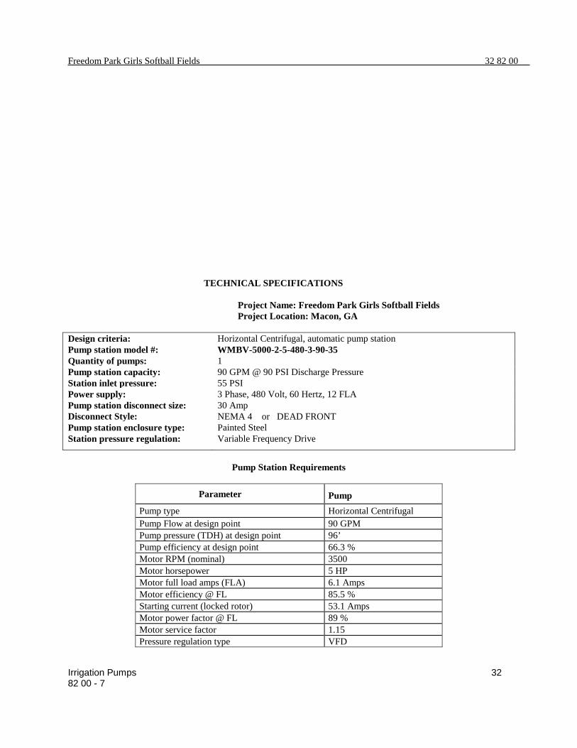
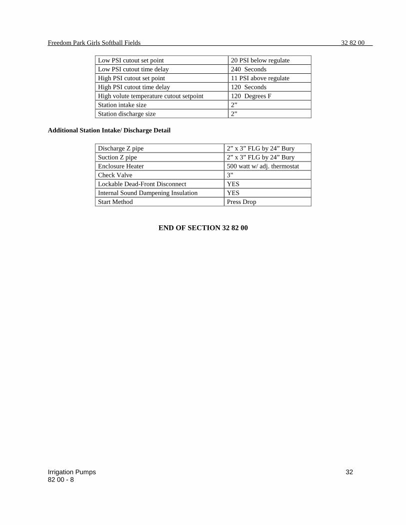
Section 32 1300 ConcreteSection 32 1313 Concrete Paving, Sidewalks & Curb and GuttersSection 32 1316 Asphalt Concrete PavingSection 32 3113 Chain Link Fences and GatesSection 32 8000 Underground Irrigation SystemSection 32 8200 Variable Frequency Drive Pump StationSection 32 9000 PlantingSection 32 9119.13 Topsoil Placement and GradingSection 32 9210 Athletic Fields Construction
DIVISION 33 UTILITIES
Section 33 1116 Site Water Distribution and Fire MainsSection 33 3313 Sanitary Sewer ConstructionSection 33 4116 Storm Drainage
DIVISIONS 34 THROUGH 49
No Sections Required
End of Table of Contents
Freedom Park Girls Softball Fields 00 0110-1SG-16190FREEPK Table of ContentsSBA-16131
VOLUME 2 OF 2
TABLE OF CONTENTS
INTRODUCTORY INFORMATION
Document 00 0101 Project Title PageDocument 00 0110 Table of Contents
DIVISION 00 PROCUREMENT AND CONTRACTING REQUIREMENTS
Refer to Volume 1 for Procurement and Contracting Requirements.
Freedom Park Girls Softball Fields 00 0110-2SG-16190FREEPK Table of ContentsSBA-16131
DIVISION 4 MASONRY
Section 04 0513 Masonry Mortaring and GroutingSection 04 0523 Masonry AccessoriesSection 04 2220 Architectural Concrete Unit MasonrySection 04 2200 Structural ConcreteSection 04 2205 Site-Work - Masonry Work
DIVISION 5 METALS
Section 05 1000 Structural SteelSection 05 3000 Metal DeckingSection 05 4000 Cold-Formed Metal FramingSection 05 4100 Exterior Steel Stud SystemSection 05 5000 Site Work - Metal FabricationsSection 05 5500 Building - Metal FabricationsSection 05 7000 Decorative Metal Panels and Gates
Section 13 1175 Splash Pad (Refer to accompanying Project Manual entitled“Freedom Park Splash Pad, Macon, GA - WATERSPLASH”.
DIVISIONS 14 THROUGH 21
No Sections Required
DIVISION 22 PLUMBING
Section 22 0510 General Plumbing RequirementsSection 22 0519 Meters and Gauges for Plumbing PipingSection 22 0553 Identification for Plumbing Piping and EquipmentSection 22 0719 Plumbing Piping InsulationSection 22 1005 Plumbing PipingSection 22 1006 Plumbing Piping SpecialtiesSection 22 3000 Plumbing EquipmentSection 22 4010 Plumbing Fixtures
DIVISION 23 HEATING VENTILATING AND AIR CONDITIONING
Section 23 0001 Heating, Ventilation and Air-Conditioning Specifications
DIVISIONS 24 AND 25
No Sections Required
DIVISION 26 ELECTRICAL
Section 26 0002 Building - Electrical SpecificationsSection 26 6010 Site Work - GeneralSection 26 6100 Site Work - Basic Materials and MethodsSection 26 6400 Site Work - Electrical Service and Distribution EquipmentSection 26 6450 Site Work - GroundingSection 26 6500 Site Work - Sports Lighting System
Freedom Park Girls Softball Fields 00 0110-4SG-16190FREEPK Table of ContentsSBA-16131
DIVISIONS 27 AND 30
No Sections Required
DIVISION 31 EARTHWORK
Section 31 1000 Building DemolitionSection 31 1005 Site DemolitionSection 31 2300 EarthworkSection 31 2301 Excavating, Backfilling, and Compacting for StructuresSection 31 2305 Site PreparationSection 31 2500 Erosion, Siltation and Dust ControlSection 31 3116 Termite Control
DIVISION 32 EXTERIOR IMPROVEMENTS
Section 32 1300 ConcreteSection 32 1313 Concrete Paving, Sidewalks & Curb and GuttersSection 32 1316 Asphalt Concrete PavingSection 32 3113 Chain Link Fences and GatesSection 32 8000 Underground Irrigation SystemSection 32 8200 Variable Frequency Drive Pump StationSection 32 9000 PlantingSection 32 9119.13 Topsoil Placement and GradingSection 32 9210 Athletic Fields Construction
DIVISION 33 UTILITIES
Section 33 1116 Site Water Distribution and Fire MainsSection 33 3313 Sanitary Sewer ConstructionSection 33 4116 Storm Drainage
DIVISIONS 34 THROUGH 49
No Sections Required
End of Table of Contents
Freedom Park Girls Softball Fields 00 0110-1SG-16190FREEPK Table of ContentsSBA-16131
TABLE OF CONTENTS
DIVISION 00 PROCUREMENT AND CONTRACTING REQUIREMENTS
INTRODUCTORY INFORMATION
Document 00 0101 Project Title PageDocument 00 0110 Table of Contents
PROCUREMENT REQUIREMENTS
(To be provided by Macon-Bibb County Procurement Dept.)
Freedom Park Girls Softball Fields 00 0110-3SG-16190FREEPK Table of ContentsSBA-16131
DIVISION 11 EQUIPMENT
Section 11 4000 Food Service Equipment
DIVISION 12 FURNISHINGS
Section 12 3616 Metal Countertops
DIVISIONS 13 THROUGH 21
No Sections Required
DIVISION 22 PLUMBING
Section 22 0510 General Plumbing RequirementsSection 22 0519 Meters and Gauges for Plumbing PipingSection 22 0553 Identification for Plumbing Piping and EquipmentSection 22 0719 Plumbing Piping InsulationSection 22 1005 Plumbing PipingSection 22 1006 Plumbing Piping SpecialtiesSection 22 3000 Plumbing EquipmentSection 22 4010 Plumbing Fixtures
DIVISION 23 HEATING VENTILATING AND AIR CONDITIONING
Section 23 0001 Heating, Ventilation and Air-Conditioning Specifications
DIVISIONS 24 AND 25
No Sections Required
DIVISION 26 ELECTRICAL
Section 26 0002 Building - Electrical SpecificationsSection 26 6010 Site Work - GeneralSection 26 6100 Site Work - Basic Materials and MethodsSection 26 6400 Site Work - Electrical Service and Distribution EquipmentSection 26 6450 Site Work - GroundingSection 26 6500 Site Work - Sports Lighting System
DIVISION 27 COMMUNICATIONS
Sections by Consultant
DIVISION 28 ELECTRONIC SAFETY AND SECURITY
Sections by Consultant
DIVISIONS 29 AND 30
No Sections Required
Freedom Park Girls Softball Fields 00 0110-4SG-16190FREEPK Table of ContentsSBA-16131
DIVISION 31 EARTHWORK
Section 31 1000 Building DemolitionSection 31 2300 EarthworkSection 31 2301 Excavating, Backfilling, and Compacting for StructuresSection 31 2500 Erosion, Siltation and Dust ControlSection 31 3116 Termite Control
DIVISION 32 EXTERIOR IMPROVEMENTS
Section 32 1313 Concrete Paving, Sidewalks & Curb and GuttersSection 32 1316 Asphalt Concrete Paving Section 32 8200 Variable Frequency Drive Pump StationSection 32 8400 Underground Irrigation System Section 32 9210 Athletic Fields Construction
DIVISION 33 UTILITIES
Section 33 1116 Site Water Distribution and Fire MainsSection 33 3313 Sanitary Sewer ConstructionSection 33 4116 Storm Drainage
DIVISIONS 34 THROUGH 49
No Sections Required
End of Table of Contents
Freedom Park Girls Softball Fields
01 11 00 - 1
SECTION 01 11 00
SUMMARY OF WORK 1.1 GENERAL
A. The Project consists of
1. Project Location: Freedom Park– Macon, Georgia 2. Owner: Macon/Bibb County Parks and Recreation Department
B. Construction Documents – Dec 2016, prepared Mack Cain Design Studio, a division
of Travis Pruitt and Associates, Norcross, GA Project Manual – Jan 2017
Volume 1 - Bid Instructions and Construction Bid Items Schedule Volume 2 -Technical Specifications C. The Work consists of:
1. Staking of the plan on the site 2. Demolition of existing pool, buildings, ballfields, paving, road, and site items. 3. Erosion Control to local ordinance and code standards 4. Clearing and Grading of the site 5. Removal or capping of existing site utilities, drainage, and lighting 6. Construction of new utilities for storm, water, power, lighting 7. Construction of Concessions Building and Splash Pad Restrooms 8. Construction of field fences, paving, footings, dugouts, roofs, gates, and backstops 9. Installation of complete Sports Lighting system for 4 fields. 10. Construction of a Splash Pad 11. Installation of complete irrigation system 12. Installation of Landscape Materials and field turf. 13. Construction of a new city road (Morgan Road) and parking 14. Final clean up. 15. All other items identified on the Construction Bid Items Schedule and shown or
implied by the Drawings and Specifications. D. The Work shall be constructed under a single contract as shown on the plans. E. Cooperate with the Freedom Park staff so that work may be carried out smoothly,
without interfering with or unnecessarily delaying use of the recreation center. F. Contractor Use of Premises: During construction the Contractor shall have use of
premises, including the immediate site. The Contractor's use of premises is limited only by the Owner's right to have a safe environment for park and recreation center visitors.
Freedom Park Girls Softball Fields
01 11 00 - 2
G. Use of the Site: Limit use of premises to areas indicated. Do not disturb portions of the site beyond the disturbed areas. Do not cross onto adjacent property. 1. Actual limits of construction to be determined with the Owner in the field. 2. Allow for Owner use of undisturbed areas of the park. 3. Keep roadways and entrances clear. Do not use these areas of parking for
materials storage without consent of the Owner. Schedule deliveries to minimize on-site storage of materials and equipment.
4. No interference with recreation center, adjacent park and facilities. 5. Contractor shall protect the existing vegetation and structures within the work
area. 6. Contractor shall establish a suitable schedule with the Owner.
H. Owner Occupancy: The Owner shall not use the site until after construction is
completed and the designated work is accepted. I. Work includes providing support systems to receive equipment and materials on site.
1. The Owner shall arrange for Contractor to have necessary access to the site to begin his pre-construction work.
2. Contractor shall not damage any adjacent materials, paving, turf grass, irrigation or other property in the park.
3. The Owner shall inspect items delivered for damage. 4. If items are damaged, defective, or missing, the Contractor shall arrange for
replacement. 5. The Owner shall allow for field survey operations by the Contractor. 7. The Contractor shall present field survey data to the Owner for use by the
Landscape Architect. 8. The Contractor is responsible for receiving, unloading, and handling all
materials at the site. 9. The Contractor is responsible for protecting items from damage, including
exposure to the elements. The Contractor shall repair or replace items damaged as a result of his operations.
10. Contractor shall arrange with the Owner in the event there is a need to cut or undermine any service or utility lines on the site.
11. Contractor and Owner shall coordinate the best route access to and from the construction site.
END OF SECTION 01 11 00
Freedom Park Girls Softball Fields
Modification Procedures 01 26 00 - 1
SECTION 01 26 00 MODIFICATION PROCEDURES
1.1 GENERAL
A. Minor Changes in the Work: The Landscape Architect will issue instructions authorizing changes in the Work that do not alter the contract amount on AIA Form G710.
B. Owner-Initiated Change Order Proposal Requests: The Landscape Architect will issue a
description of proposed changes in the Work that require adjustment to the Contract Sum or Time. The description may include supplemental or revised Drawings and Specifications.
1. Proposal requests are for information only. Do not consider them an instruction to
stop work or to execute the proposed change.
2. Within 20 days of receipt, submit an estimate of cost necessary to execute the change for the Owner's review.
a. Include an itemized list of products required and unit costs, with the total amount of purchases.
b. Indicate taxes, delivery charges, equipment rental, and amounts of trade discounts.
c. Indicate the effect the change will have on the Contract Time.
C. Contractor-Initiated Proposals: When unforeseen conditions require modifications, the Contractor may submit a request for a change to the Landscape Architect. 1. Describe the proposed change. Indicate reasons for the change and the effect of the
change on the Contract Sum and Time. 2. Include an itemized list of products required and unit costs, with the total amount of
purchases. 3. Indicate taxes, delivery charges, equipment rental, and amounts of trade discounts. 4. Additional work already included on the Schedule of Values shall be submitted at
the same price as originally quoted unless otherwise agreed prior to submittal.
D. Proposal Request Form: Use AIA Document G709.
E. Allowance Adjustment: Base Change Order Proposals on the difference between the purchase amount and the allowance, multiplied by the measurement of work-in-place. Allow for cutting losses, tolerances, mixing wastes, normal product imperfections, and similar margins.
1. Include installation costs when indicated as part of the allowance. 2. Identify all charges against the allowance to validate exhaustion of the allowance. 3. Prepare explanations and documentation to substantiate additions claimed. 4. Submit substantiation of a change in work claimed in the Change Orders related to
allowances.
Freedom Park Girls Softball Fields 01 26 00
Modification Procedures 01 26 00 - 2
F. Submit claims to increase costs due to a need to change an allowance, whether for
purchase order amount or handling, labor, installation, overhead, and profit. Submit claims within 21 days of receipt of authorization to proceed. The Owner will reject claims submitted later than 21 days.
1. Do not include indirect expense in cost amount unless the Work has changed from
that described in Contract Documents. 2. No change to indirect expense is permitted for selection of higher- or lower-priced
materials or systems of the same scope and nature as originally indicated.
G. Construction Change Directive: When Owner and Contractor disagree on the terms of a Proposal Request, the Architect may issue a Construction Change Directive on AIA Form G714 instructing the Contractor to proceed with a change.
1. The Construction Change Directive contains a description of the change and
designates the method to be followed to determine change in the Contract Sum or Time.
H. Documentation: Maintain detailed records on a time and material basis of work required
by the Construction Change Directive.
1. After completing the change, submit an itemized account and supporting data to substantiate Contract adjustments.
I. Change Order Procedures: Upon the Owner's approval of a Proposal Request, the
Architect will issue a Change Order on AIA Form G701. J. Contractor shall submit Requests for Information (RFI) whenever items or parts of the
central documents are unclear or incorrect. Contractor shall maintain a list of Requests by the number and date with responses from the Landscape Architect.
K. Unit Item Cost: When changes effect unit items for which costs have already been
established, change request must utilize the agreed unit prices for future additions or deletions.
A. Coordinate the Construction Bid Items Schedule and Applications for Payment with the Contractor's Schedule of Values, Submittal Schedule, and List of Subcontracts.
B. Coordinate preparation of the Construction Bid Items Schedule with preparation of the
Contractor's Project Construction Time Schedule of Work.
1. Correlate line items in the Construction Schedule of Values with other required administrative schedules and forms, including:
a. Contractor's Project Construction Time Schedule. b. Application for Payment forms, including Continuation Sheets. c. List of subcontractors and consultants. d. List of products. e. List of principal suppliers and fabricators. f. Schedule of submittals.
2. Submit the Project Construction Time Schedule at the earliest possible date but no
later than 7 days before the date scheduled for submittal of the initial Application for Payment.
C. Format and Content: Use the Construction Bid Items Schedule as the format for
establishing a Schedule of Values for Payments. Provide at least one line item for each Unit Item on the Construction Schedule of Values as a payment item.
1. Include the Name of the Project as the Project Identification:
a. Project name and location:
Freedom Park Girls Softball Fields, 3301 Roff Avenue, Macon, GA 31204.
b. Name of Architect: Mack Cain Design Studio c. Project number: 15-0536 d. Contractor's name and address e. Date of submittal;
2. Arrange the Schedule of Values for Payment in tabular form with separate columns to
indicate the following for each item listed:
a. Item number b. Name of the item c. Total quantity of the item
Freedom Park Girls Softball Fields 01 29 00
Application For Payment 01 29 00 - 2
d. Unit price e. Total price f. Current work completed by dollar value g. Previous dollar amount completed h. Total amount requested this payment h. Percentage of Total line item Sum to nearest one-hundredth percent
3. Provide separate back up for each item of the Work where Applications for Payment
include materials or equipment, purchased or fabricated and stored, but not yet installed.
4. Change Orders or Construction Change Directives that change the Contract Sum must be pre-approved before commencing the work or applying for payment. Pre-approved change orders may be attached to the application for payment after completion and acceptance of the work.
5. Approved Change Orders become additional line items at the bottom of the Schedule
of Values. 6. Maintain a ledger list of deletions or additions to the contract amount that have not
been converted to a ‘Change Order” to be attached to each Pay Request. 7. Consultant will provide a sample Pay Request if requested by contractor.
D. Applications for Payment shall be consistent with previous applications and payments as certified by the Owner Representative and paid for by the Owner.
E. Payment-Application Times: Payment dates are indicated in the Agreement. The period
covered by each application is the period indicated in the Agreement.
F. Payment-Application Forms: Use AIA Document G702 and Continuation Sheets G703 as the form for Applications for Payment, or form supplied by the Owner.
G. Application Preparation: Complete every entry, including notarization and execution by a
person authorized to sign on behalf of the Contractor. The Architect will return incomplete applications without action.
1. Entries shall match data on the Schedule of Values and the Contractor's Construction
Time Schedule. Use updated schedules if revisions were made. 2. Include amounts of Change Orders and Construction Change Directives approved
prior to the last day of the construction period covered by the application.
H. Transmittal: Submit 3 executed original copies of each Application for Payment (Pay Request) to the Owner Representative within 24 hours. One copy shall be complete, including waivers of lien and similar attachments.
Freedom Park Girls Softball Fields 01 29 00
Application For Payment 01 29 00 - 3
1. Transmit each copy with a transmittal listing attachments and recording appropriate information related to the application.
I. Waivers of Mechanics Lien: With each Application for Payment, submit waivers of lien
from every entity who may file a lien arising out of the Contract and related to the Work covered by the payment.
1. Submit partial waivers on each item for the amount requested, prior to deduction for
retainage, on each item. 2. When an application shows completion of an item, submit final or full waivers. 3. Submit each Application for Payment with Contractor's waiver of lien for the period
of construction covered by the application. 4. Submit final Applications for Payment with final waivers from every entity involved
with performance of the work covered by the application who may file a lien. 5. Waiver Forms: Submit waivers of lien on forms, and executed in a manner,
acceptable to the Owner.
J. Initial Application for Payment: Administrative actions and submittals that must precede or coincide with submittal of the first Application for Payment include the following:
Provisions of the contract regarding payment shall supersede any applicable provisions of the Georgia Prompt Payment Act.
1. List of subcontractors. 2. List of principal suppliers and fabricators. 3. Schedule of Payments. 4. Contractor's Construction Time Schedule (preliminary if not final). 5. Submittal Schedule (preliminary if not final). 6. List of Contractor's staff assignments. 7. Copies of land disturbance and building permits. 8. Copies of licenses from governing authorities. 9. Certificates of insurance and insurance policies. 10. Performance and payment bonds.
K. Application for Payment at Substantial Completion: Following issuance of the
Certificate of Substantial Completion, submit an Application for Payment. This application shall reflect Certificates of Partial Substantial Completion issued previously for Owner Occupancy of designated portions of the Work.
1. Administrative actions and submittals that shall precede or coincide with this
application include the following:
Provisions of the contract regarding payment shall supersede any applicable provisions of the Georgia Prompt Payment Act:
a. Occupancy permits. b. Warranties and maintenance agreements.
Freedom Park Girls Softball Fields 01 29 00
Application For Payment 01 29 00 - 4
c. Test/adjust/balance records. d. Maintenance instructions. e. Meter readings (if necessary). f. Changeover information related to Owner's occupancy. g. Final clean up. h. Application for reduction of retainage and consent of surety. l. Final Payment Application: Administrative actions and submittals that must
precede or coincide with submittal of the final Application for Payment include the following:
L. Retainage: Client shall retain 10% of all approved Pay Requests until substantial
completion of the project. Retainage shall drop to 5% until substantial completion inspection and acceptance. 1. Completion of Project closeout requirements. 2. Completion of items specified for completion after Substantial Completion. 3. Transmittal of Project construction records to the Owner. 4. Delivery of As-built documents. 5. Proof that taxes, fees, and similar obligations were paid. 6. Removal of temporary facilities and services. 7. Fulfillment of all erosion control measures.
M. Final Ledger: Contractor shall request payment for 100% of all construction items as shown on the Construction Schedule of Values.
The final tabulation of the ledger will be either a subtraction from the total contract or an addition. In the case of subtractions the contractor shall enter the total deleted at the bottom of the request. In the case of an addition, the Landscape Architect shall prepare a final change order for approval as part of the final pay request.
A. This Section specifies administrative and procedural requirements for project
meetings, including, but not limited to, the following: 1. Preconstruction conferences. 2. Pre-installation stakeout conferences as determined in the field. 3. Progress meetings with Owners Representative once a week. 4. Weather Records and Calendar 5. Contractor to keep meeting minutes to distribute to all parties.
B. Preconstruction Conference: Schedule a preconstruction conference at the site before
starting construction. Review responsibilities and personnel assignments. Attendees: Authorized representatives of the Owner, Landscape Architect, special
consultants, Contractor and superintendent; major subcontractors; and other involved parties needed shall attend. 1. Participants shall be familiar with the Project and authorized to conclude matters
relating to the Work. Agenda: Discuss items that could affect progress, including the following:
1. Tentative construction schedule 2. Staking layout process and sequence. 3. Submittal of Shop Drawings, Product Data, and Samples as required. 4. Schedule use of the premises by the Parks Department and general public. 5. Turn on the existing irrigation to document conditions 6. Weather conditions and installation schedule
C. Pre-installation stakeout conferences: Conduct a conference before each major
activity that requires coordination with other operations. Attendees: The Installer and representatives of manufacturers and fabricators involved
in or affected by the installation shall attend the meeting. Contractor to advise the Landscape Architect of scheduled meeting dates. 1. Review progress of other operations and preparations for the activity under
consideration at each progress schedule, including requirements for the following: a. Review field stakeout and make adjustments. b. Time schedules and deliveries. c. Manufacturer's recommendations and warranties. d. Warranty requirements on chain link.
Freedom Park Girls Softball Fields 01 31 19
Project Meetings 01 31 19 - 2
e. Manufactures data on building systems and products. 3. Record significant discussions and agreements and disagreements, and the
approved changes in the stakeout. Promptly distribute the record of the meeting to everyone concerned, including the Owner and the Landscape Architect.
3. Do not proceed with the installation if the conference cannot be successfully
concluded. Initiate actions necessary to resolve problems and reconvene the conference.
D. Progress Meetings: Conduct progress meetings at the Project Site at regular intervals
as agreed in the bid process. Notify the Owner and the Architect of scheduled dates. Coordinate meeting dates with preparation of the payment request.
Attendees: The Owner, Landscape Architect, and other parties involved with current
progress, planning, coordination, or future activities shall be represented. Participants shall be authorized to conclude matters relating to the Work.
Agenda: Review and correct or approve minutes of the previous meetings. Review
items of significance that could affect progress. Include topics for discussion appropriate to Project status. 1. Contractor's Construction Schedule: Review progress since the last meeting.
Determine where each activity is in relation to the Contractor's Construction Schedule. Determine how to expedite construction behind schedule; secure commitments from parties involved. Discuss revisions required to insure subsequent activities will be completed within the Contract Time.
2. Review the present and future needs of each entity present, including the following: a. Time. b. Sequences. c. Status of submittals and shop drawings. d. Deliveries and off-site fabrication problems. e. Temporary facilities and services. f. Quality and work standards. g. Change Orders. h. Daily reports and weather conditions i. On-site inspections and stakeout adjustments
3. Reporting: Distribute meeting minutes to each party present and to parties who
should have been present. Include a summary of progress since the previous meeting and report.
4. Schedule Updating: Revise the Contractor's Construction Schedule after each meeting where revisions have been made. Issue the revised schedule concurrently with the report of each meeting.
Freedom Park Girls Softball Fields 01 31 19
Project Meetings 01 31 19 - 3
6. Record Drawings: Contractor shall maintain a current and complete set of Contract Documents on-site at all times for receiving markups and comments.
7. Review ‘Requests for Information’ and resolve. 8. Review ‘Change Orders’ and resolve. 9. Review pay requests and schedule of payments. 10. Resolve on-site issues and adjustments. 11. Review weather reports and status of schedule and delays.
E. Construction Records: Contractor shall maintain the following reports and records for
review at each Project Meeting. See Section 01 32 19 Submittals for more detail of each report.
1. Daily Reports:
a. Daily record showing work engaged, completed, and started b. Materials delivered or stored c. Inspection or testing completed d. Official visitors to the site e. Weather conditions and rain delays
2. As-Built Field Set:
Set of contract plans kept inside the field office for the purpose of updating and recording all changes and modifications.
3. Request for Information (RFI) record book:
Sequential record of all requests and their subsequent responses.
4. Pay Requests: Maintain copies of each pay request on site for reference.
5. Change Orders: Sequential record of all accepted or pending change orders with backup data.
The following minimum items must be submitted on this project. 1. Chain link vinyl clad fabric 2. Post caps 3. Post sections of each size post 4. Clamps, fasteners and wires to assemble chain link fence 5. Piece of wind screen 6. Metal roof material sample in color 7. Manufactures cut sheets for bleacher, bench, and bike rack. 8. Irrigation submittals as required in the Technical Specifications 9. Lighting submittals as required in the Technical Specifications 10. Landscape Material submittals as required in the Technical Specifications
A. Submittal Procedures: Coordinate submittal preparation with construction, fabrication,
other submittals, and activities that require sequential operations. Transmit in advance of construction operations to avoid delay. 1. Coordinate submittals for related operations to avoid delay because of the need to
review submittals concurrently for coordination. The Landscape Architect reserves the right to withhold action on a submittal requiring coordination until related submittals are received.
2. Processing: Allow 2 weeks for initial review. Allow more time if the Landscape Architect must delay processing to permit coordination. Allow 2 weeks for reprocessing.
3. Submittal Preparation: Place a permanent label on each submittal for
identification. Provide a 4- by 5-inch space on the label or beside title block to record review and approval markings and action taken. Include the following information on the label for processing and recording action taken. a. Project name. b. Date. c. Name and address of the Engineer/Landscape Architect. d. Name and address of the Contractor. e. Name and address of the subcontractor. f. Name and address of the supplier. g. Name of the manufacturer. h. Number and title of appropriate Specification Section. i. Drawing number and detail references, as appropriate.
Freedom Park Girls Softball Fields 01 32 19
Submittals 01 32 19 - 2
4. Submittal Transmittal: Package each submittal appropriately. Transmit with a transmittal form. The Landscape Architect will not accept submittals from sources other than the Contractor.
5. Transmittal Form: Use AIA Document G810. On the form, record requests for
information and deviations from requirements. Include Contractor's certification that information complies with requirements.
B. Contractor's Construction Schedule: Prepare a horizontal bar-chart-type, contractor's
construction schedule. Provide a separate time bar for each activity and a vertical line to identify the first working day of each week. Use the same breakdown of Work indicated in the "Schedule of Values." Indicate estimated completion in 10 percent increments. As Work progresses, mark each bar to indicate actual completion.
1. Submit on date of Pre-Construction Meeting. 2. Prepare the schedule on reproducible media, of width to show data for the entire
construction period. 3. Secure performance commitments from parties involved. Coordinate each
element with other activities; include minor elements involved in the Work. Show each activity in proper sequence. Indicate sequences necessary for completion of related Work.
4. Coordinate with the Schedule of Payment, list of subcontracts, Submittal Schedule, payment requests, and other schedules.
5. Indicate completion in advance of Substantial Completion. Indicate Substantial Completion to allow time for the Landscape Architect's procedures necessary for certification of Substantial Completion.
6. Phasing: Show how phased completion affects the Work. 7. Work Stages: Indicate important stages for each portion of the Work. 8. Area Separations: Provide a separate time bar to identify each construction area
(field) for each portion of the Work. Indicate where each element must be sequenced with other activities.
C. Submittal Schedule: After developing the Contractor's Construction Schedule, prepare
a schedule of submittals to submit within 10 days. 1. Coordinate with list of subcontracts, Schedule of Values, list of products, and the
Contractor's Construction Schedule. 2. Prepare the schedule in chronological order. Provide the following information:
a. Date for first submittal. b. Related Section number. c. Submittal category (Shop Drawings, Product Data, or Samples). d. Name of the subcontractor. e. Description of the Work covered. f. Date for the Landscape Architect's final approval.
Freedom Park Girls Softball Fields 01 32 19
Submittals 01 32 19 - 3
3. Schedule Distribution: Distribute copies of the Contractor's Construction Schedule and the Submittal Schedule to the Architect, Owner, subcontractors, and parties required to comply with submittal dates. Post copies in the field office. a. When revisions are made, distribute to the same parties and post in the same
locations. Delete parties from distribution when they have completed their Work and are no longer involved in construction activities.
b. Updating: Revise the schedule after each meeting or activity where revisions have been made. Issue updated schedule concurrently with the report of each meeting.
D. Daily Construction Reports: Prepare a daily report recording events at the site. Submit
duplicate copies to the Architect at weekly intervals. Include the following information: 1. List of subcontractors at the site. 2. High and low temperatures, general weather conditions. 3. Accidents and unusual events. 4. Work stoppages, delays, shortages, and losses. 5. Meter readings and similar recordings. 6. Emergency procedures and events. 7. Orders and requests of governing authorities. 8. Services connected, disconnected. 9. Material delivery and storage 9. Equipment or system tests and startups. 10. Visitors, meetings and inspections on site 10. Substantial Completions authorized.
E. Shop Drawings: Submit newly prepared information drawn to scale. Indicate
deviations from the Contract Documents. Do not reproduce Contract Documents or copy standard information. Include the following information: 1. Dimensions. 2. Identification of products and materials included by sheet and detail number. 3. Compliance with standards and contract documents. 4. Notation of coordination requirements. 5. Notation of dimensions revised by field measurement. 6. Sheet Size: Except for templates and full-size Drawings, submit one correctable,
reproducible print and one blue- or black-line print on sheets at least 8-1/2 by 11 inches (215 by 280 mm) but no larger than 36 by 48 inches (890 by 1220 mm). The Architect will return the reproducible print. a. Do not use Shop Drawings without an appropriate final stamp indicating
action taken. F. Product Data: Collect Product Data into a single submittal for each element of
construction. Mark each copy to show applicable choices and options. Where Product Data includes information on several products, mark copies to indicate applicable information. 1. Include the following information:
Freedom Park Girls Softball Fields 01 32 19
Submittals 01 32 19 - 4
a. Manufacturer's printed recommendations and manuals. b. Compliance with trade association standards. c. Compliance with recognized testing agency standards. d. Application of testing agency labels and seals. e. Notation of dimensions verified by field measurement. f. Notation of coordination requirements.
2. Preliminary Submittal: Submit a preliminary single copy of Product Data where
selection of options is required.
3. Submittals: Submit 2 copies; submit 4 copies where required for maintenance manuals. The Architect will retain one and return the other marked with action taken. a. Unless noncompliance with Contract Documents is observed, the submittal
serves as the final submittal. 4. Distribution: Furnish copies to installers, subcontractors, suppliers, and others
required for performance of construction activities. Show distribution on transmittal forms. Do not proceed with installation until a copy of Product Data is in the Installer's possession. a. Do not use unmarked Product Data for construction.
G. Samples: Submit full-size Samples cured and finished as specified and identical with
the material proposed. Mount Samples to facilitate review of qualities. 1. Include the following:
a. Specification Section number and reference. b. Generic description of the Sample. c. Sample source. d. Product name or name of the manufacturer. e. Compliance with recognized standards. f. Availability and delivery time.
2. Submit Samples for review of size, kind, color, pattern, and texture, for a check of
these characteristics, and for a comparison of these characteristics between the final submittal and the actual component as delivered and installed. Where variations are inherent in the material, submit at least 3 units that show limits of the variations. a. Refer to other Sections for requirements for Samples that illustrate
workmanship, fabrication techniques, and details of assembly, connections, operation, and similar characteristics.
b. Refer to other Sections for Samples to be incorporated in the Work. Samples must be undamaged at time of use. On the transmittal, indicate special requests regarding disposition of Sample submittals.
c. Samples not incorporated into the Work, or designated as the Owner's property, are the Contractor's property and shall be removed from the site.
Freedom Park Girls Softball Fields 01 32 19
Submittals 01 32 19 - 5
3. Preliminary Submittals: Submit a full set of choices where Samples are submitted for selection of color, pattern, texture, or similar characteristics from standard choices. The Architect will review and return submittals indicating selection and other action.
4. Submittals: Except for Samples illustrating assembly details, workmanship, fabrication techniques, connections, operation, and similar characteristics, submit 3 sets. One set will be returned marked with the action taken. Maintain sets of Samples, at the Project Site, for quality comparison. a. Unless noncompliance with Contract Documents is observed, the submittal
may serve as the final submittal. b. Sample sets may be used to obtain final acceptance of the construction
associated with each set. 5. Distribution of Samples: Distribute additional sets to subcontractors,
manufacturers, and others as required for performance of the Work. Show distribution on transmittals.
H. Quality Assurance Submittals: Submit quality-control submittals, including design data,
certifications, manufacturer's instructions, and manufacturer's field reports required under other Sections of the Specifications. 1. Certifications: Where certification that a product or installation complies with
specified requirements is required, submit a notarized certification from the manufacturer certifying compliance. a. Signature: Certification shall be signed by an officer authorized to sign
documents on behalf of the company.
I. Sample Panels: 1. Contractor shall construct sample panels in accordance with the Technical
Specifications for review and approval by Landscape Architect. 2. Samples shall be prepared in advance of construction sequencing to allow time for
modifications and approvals. 3. Contractor shall allow Landscape Architect 5 days to respond to a sample request. 4. Full scale construction of any work requiring a pre-approved sample shall not
begin until after Landscape Architect issues a statement of approval.
J. Landscape Architect's Action: Except for submittals for the record or information, where action and return are required, the Landscape Architect will review each submittal, mark to indicate action taken, and return. Compliance with specified characteristics is the Contractor's responsibility. 1. Action Stamp: The Architect will stamp each submittal with an action stamp.
The Architect will mark the stamp appropriately to indicate the action taken. 1.2 PRODUCTS (Not Applicable) 1.3 EXECUTION (Not Applicable)
SECTION 01 33 23 SHOP DRAWINGS, PRODUCT DATA, AND SAMPLES PART 1 GENERAL 1.01 SCOPE
A. The work under this Section includes submittal to the Project Landscape Architect of shop
drawings, product data and samples required by the various sections of these Specifications. The following items will require shop drawings.
1. Dugout framing and roof 2. Concession building components and equipment
B. Submittal Contents: The submittal contents required are specified in each section. C. Definitions: Submittals are categorized as follows:
1. Shop Drawings a. Shop drawings shall include technical data, drawings, diagrams, procedure and methodology, performance curves, schedules, templates, patterns, test reports, calculations, instructions, measurements and similar information as applicable to the specific item for which the shop drawing is prepared.
b. Provide newly-prepared information, on reproducible sheets, with graphic information at accurate scale (except as otherwise indicated) or appropriate number of prints hereof, with name or preparer (firm name) indicated. The Contract Drawings shall not be traced or reproduced by any method for use as or in lieu of detail shop drawings. Show dimensions and note dimensions that are based on field measurement. Identify materials and products in the work shown. Indicate compliance with standards and special coordination requirements. Do not allow shop drawings to be used in connection with the Work without appropriate final “Action” markings by the Project Landscape Architect.
c. Drawings shall be presented in a clear and thorough manner. Details shall be identified by reference to sheet and detail, specification section, schedule or room numbers shown on the Contract Drawings.
d. Minimum assembly drawings sheet size shall be 24 x 36-inches. e. Minimum detail sheet size shall be 8-1/2 x 11-inches. f. Minimum scale: (1) Detail Sheet, scale: 1/4-inch = 1 foot.
2. Product Data
a. Product data includes standard printed information on materials, products and
systems, not specially prepared for this project, other than the designation of selections from among available choices printed therein.
b. Collect required data into one submittal for each unit of work or system, and mark each copy to show which choices and options are applicable to the Project. Include manufacturer's standard printed recommendations for application and use, compliance with standards, application of labels and seals, notation of field measurements which have been checked and special coordination requirements.
3. Samples
a. Samples include both fabricated and un-fabricated physical examples of materials, products and units of work, both as complete units and as smaller portions of units of work, either for limited visual inspection or, where indicated, for more detailed testing and analysis. b. Provide units identical with final condition of proposed materials or products for the work. Include “range” samples, not less than three units, where unavoidable variations must be expected, and describe or identify variations between units of each set. Provide full set of optional samples where the Project Landscape Architect's selection is required. Prepare samples to match the Project Landscape Architect's sample where indicated. Include information with each sample to show generic description, source or product name and manufacturer, limitations and compliance with standards. Samples are submitted for review and confirmation of color, pattern, texture and “kind” by the Project Landscape Architect. Project Landscape Architect will note “test” samples, except as otherwise indicated, for other requirements, which are the exclusive responsibility of the Contractor.
4. Miscellaneous submittals related directly to the Work (non-administrative) include warranties, maintenance agreements, workmanship bonds, project photographs, survey data and reports, physical work records, statements of applicability, quality testing and certifying reports, copies of industry standards, record drawings, field measurement data, operating and maintenance materials, overrun stock, security/protection/safety keys and similar information, devices and materials applicable to the Work but not processed as shop drawings, product data or samples.
1.02 Specific Category Requirements
A. General:
Except as otherwise indicated in the individual work sections, comply with general requirements specified herein for each indicated category of submittal. Submittals shall contain:
1. The date of submittal and the dates of any previous submittals. 2. The Project title.
3. Numerical submittal numbers, starting with 1.0, 2.0, etc. Revisions to be numbered 1.1, 1.2, etc.
4. The Names of the following: a. Contractor
b. Supplier c. Manufacturer
5. Identification of the product, with the Specification section number, permanent equipment tag numbers and applicable Drawing No.
6. Field dimensions, clearly identified as such. 7. Relation to adjacent or critical features of the fields or materials. 8. Applicable standards, such as ASTM or Federal Specification numbers. 9. Notification to the Project Landscape Architect in writing, at time of submissions, of any
deviations on the submittals from requirements of the Contract Documents. 10. Identification of revisions on resubmittals. 11. An 8 x 3-inch blank space for Contractor and Project Landscape Architect stamps. 12. Contractor's stamp, initialed or signed, certifying to review of submittal, verification of
products, field measurements and field construction criteria and coordination of the information within the submittal with requirements of the Work and of Contract Documents.
13. Submittal sheets or drawings showing more than the particular item under consideration shall have all but the pertinent description of the item for review crossed out.
1.03 Routing of Submittals
A. Submittals and routine correspondence shall be routed as follows: 1. Supplier to Contractor (through representative if applicable) 2. Contractor to Project Landscape Architect 3. Project Landscape Architect to Contractor and Owner 4. Contractor to Supplier
Part 2 Products 2.01 Shop Drawings
A. Unless otherwise specifically directed by the Project Landscape Architect, make all shop drawings accurately to a scale sufficiently large to show all pertinent features of the item and its method of connection to the Work.
B. Submit all shop assembly drawings, larger than 11 x 17-inches, in the form of one reproducible transparency with two opaque prints or copies.
C. Submit all shop drawings, 11 x 17-inches and smaller, in the form of six opaque prints or copies.
D. One reproducible for all submittals larger than 11 x 17-inches and no more than three prints of other submittals will be returned to the Contractor.
2.02 Manufacturer's Literature A. Where content of submitted literature from manufacturers includes data not pertinent to this submittal, clearly indicate which portion of the contents is being submitted for the Project Landscape Architect's review. B. Submit the number of copies which are required to be returned (not to exceed (3) three) plus three copies which will be retained by the Project Landscape Architect.
2.03 Samples
A. Samples shall illustrate materials, equipment or workmanship and established standards by which completed work is judged. B. Unless otherwise specifically directed by the Project Landscape Architect, all samples shall be of the precise article proposed to be furnished. C. Submit all samples in the quantity which is required to be returned plus one sample which will be retained by the Project Landscape Architect.
2.04 Colors A. Unless the precise color and pattern is specifically described in the Contract Documents, wherever a choice of color or pattern is available in a specified product, submit accurate color charts and pattern charts to the Project Landscape Architect for review and selection. B. Unless all available colors and patterns have identical costs and identical wearing capabilities, and are identically suited to the installation, completely describe the relative costs and capabilities of each.
Part 3 Execution 3.01 Contractor's Coordination of Submittals
A. Prior to submittal for the Project Landscape Architect's review, the Contractor shall use all
means necessary to fully coordinate all material, including the following procedures: 1. Determine and verify all field dimensions and conditions, catalog numbers and
similar data. 2. Coordinate as required with all trades and all public agencies involved. 3. Submit a written statement of review and compliance with the requirements of
all applicable Technical Specifications as well as the requirements of this Section.
4. Clearly indicate in a letter or memorandum on the manufacturer's or fabricator's letterhead, all deviations from the Contract Documents.
B. Each and every copy of the shop drawings and data shall bear the Contractor's stamp
showing that they have been so checked. Shop drawings submitted to the Project Landscape Architect without the Contractor's stamp will be returned to the Contractor for conformance with this requirement.
C. The Owner may back charge the Contractor for costs associated with having to
review a particular shop drawing, product data or sample more than two times to receive a “No Exceptions Taken” mark.
D. Grouping of Submittals 1. Unless otherwise specifically permitted by the Project Landscape Architect,
make all submittals in groups containing all associated items. 2. No review will be given to partial submittals of shop drawings for items which
interconnect and/or are interdependent. It is the Contractor's responsibility to assemble the shop drawings for all such interconnecting and/or interdependent items, check them and then make one submittal to the Project Landscape Architect along with Contractor's comments as to compliance, non-compliance or features requiring special attention.
E. Schedule of Submittals
1. Within 30 days of Contract award and prior to any shop drawing submittal, the Contractor shall submit a schedule showing the estimated date of submittal and the desired approval date for each shop drawing anticipated. A reasonable period shall be scheduled for review and comments. Time lost due to unacceptable submittals shall be the Contractor's responsibility and some time allowance for resubmittal shall be provided. The schedule shall provide for submittal of items which relate to one another to be submitted concurrently.
3.02 Timing of Submittals A. Make all submittals far enough in advance of scheduled dates for installation to
provide all required time for reviews, for securing necessary approvals, for possible revision and resubmittal, and for placing orders and securing delivery.
B. In scheduling, allow sufficient time for the Project Landscape Architect's review
3.03 Reviewed Shop Drawings A. Project Landscape Architect Review 1. Allow a minimum of 30 days for the Project Landscape Architect's initial
processing of each submittal requiring review and response, except allow longer periods where processing must be delayed for coordination with subsequent submittals. The Project Landscape Architect will advise the Contractor promptly when it is determined that a submittal being processed must be delayed for coordination. Allow a minimum of two weeks for reprocessing each submittal. Advise the Project Landscape Architect on each submittal as to whether processing time is critical to progress of the Work, and therefore the Work would be expedited if processing time could be foreshortened.
2. Acceptable submittals will be marked “No Exceptions Taken”. A minimum of
three copies will be retained by the Project Landscape Architect for Project Landscape Architect's and the Owner's use and the remaining copies will be returned to the Contractor.
3. Submittals requiring minor corrections before the product is acceptable will be
marked “Make Corrections Noted”. The Contractor may order, fabricate and ship the items included in the submittals, provided the indicated corrections are made. Drawings must be resubmitted for review and marked “No Exceptions Taken” prior to installation or use of products.
4. Submittals marked “Amend and Resubmit” must be revised to reflect required
changes and the initial review procedure repeated. 5. The “Rejected - See Remarks” notation is used to indicate products which are
not acceptable. Upon return of a submittal so marked, the Contractor shall repeat the initial review procedure utilizing acceptable products.
6. Only two copies of items marked “Amend and Resubmit” and “Rejected - See
Remarks” will be reviewed and marked. One copy will be retained by the Project Landscape Architect and the other copy with all remaining unmarked copies will be returned to the Contractor for resubmittal.
B. No work or products shall be installed without a drawing or submittal bearing the
“No Exceptions Taken” notation. The Contractor shall maintain at the job site a complete set of shop drawings bearing the Project Landscape Architect's stamp.
C. Substitutions: In the event the Contractor obtains the Project Landscape Architect's
approval for the use of products other than those which are listed first in the Contract Documents, the Contractor shall, at the Contractor's own expense and using methods
approved by the Project Landscape Architect, make any changes to structures, piping and electrical work that may be necessary to accommodate these products.
D. Use of the “No Exceptions Taken” notation on shop drawings or other submittals is
general and shall not relieve the Contractor of the responsibility of furnishing products of the proper dimension, size, quality, quantity, materials and all performance characteristics, to efficiently perform the requirements and intent of the Contract Documents. The Project Landscape Architect's review shall not relieve the Contractor of responsibility for errors of any kind on the shop drawings. Review is intended only to assure conformance with the design concept of the Project and compliance with the information given in the Contract Documents. The Contractor is responsible for dimensions to be confirmed and correlated at the job site. The Contractor is also responsible for information that pertains solely to the fabrication processes or to the technique of construction and for the coordination of the work of all trades.
3.04 Resubmission Requirements
A. Shop Drawings 1. Revise initial drawings as required and resubmit as specified for initial
submittal, with the resubmittal number shown. 2. Indicate on drawings all changes which have been made other than those
requested by the Project Landscape Architect.
B. Project Data and Samples: Resubmit new data and samples as specified for initial submittal, with the resubmittal number shown.
END OF SECTION 01 33 23
Freedom Park Girls Softball Fields
Execution and Closeout Requirements 01 70 00 - 1
SECTION 01 70 00
CONTRACT CLOSEOUT 1.1 GENERAL
A. Closeout requirements for specific construction activities are included in the appropriate
Sections of the Technical Specifications. B. Substantial Completion: Before requesting inspection for certification of Substantial
Completion, complete the following: 1. In the Application for Payment that coincides with, or first follows, the date
Substantial Completion is claimed, show 100 percent completion for the Work claimed as substantially complete. a. Include supporting documentation for completion and an accounting of
changes to the Contract Sum. 2. Advise the Owner of pending insurance changeover requirements. 3. Submit specific warranties, workmanship bonds, maintenance agreements, final
certifications, and similar documents. 4. Submit record drawings, maintenance manuals, final project photographs, damage
or settlement surveys, property surveys, and similar final record information. 5. Deliver tools, spare parts, extra stock, and similar items. 6. Turn on existing irrigation system to determine if damage was done during work. 7. Remove temporary facilities, mockups, construction tools, and similar elements. 8. Complete final cleanup requirements, including touchup painting. 9. Touch up and repair and restore marred, exposed finishes. 10. Repair ballfields and parking lots used for storage and staging.
C. Inspection Procedures: On receipt of a request for inspection, the Architect will proceed
or advise the Contractor of unfilled requirements. The Architect will prepare the Certificate of Substantial Completion following inspection or advise the Contractor of construction that must be completed or corrected before the certificate will be issued. 1. The Landscape Architect/Engineer will repeat inspection when requested and
assured that the Work is substantially complete. 2. Results of the completed inspection will form the basis of requirements for final
acceptance. D. Final Acceptance: Before requesting inspection for certification of final acceptance and
final payment, complete the following: 1. Final payment request with releases and supporting documentation. Include
insurance certificates where required. 2. Submit a statement, accounting for changes to the Contract Sum. 3. Submit a copy of the final inspection list stating that each item has been
completed or otherwise resolved for acceptance.
Freedom Park Girls Softball Fields 01 70 00
Execution and Closeout Requirements 01 70 00 -2
4. Submit final meter readings for utilities, a record of stored fuel, and similar data as of the date of Substantial Completion.
5. Submit consent of surety to final payment. 6. Submit a final settlement statement. 7. Submit evidence of continuing insurance coverage complying with insurance
requirements. E. Re-inspection Procedure: The Landscape Architect will re-inspect the Work upon
receipt of notice that the Work has been completed, except for items whose completion is delayed under circumstances acceptable to the Landscape Architect. 1. Upon completion of re-inspection, the Landscape Architect will prepare a
certificate of final acceptance. If the Work is incomplete, the Landscape Architect will advise the Contractor of Work that is incomplete or obligations that have not been fulfilled but are required.
2. If necessary, re-inspection will be repeated. F. Record Document Submittals: Do not use record documents for construction. Protect
from loss in a secure location. Provide access to record documents for the Landscape Architect's reference.
G. Record Drawings: Maintain a set of prints of Contract Drawings and Shop Drawings.
Mark the set to show the actual installation where the installation varies substantially from the Work as originally shown. Mark the drawing most capable of showing conditions fully and accurately. Give attention to concealed elements. 1. Mark sets with red pencil. Use other colors to distinguish between variations in
separate categories of the Work. 2. Organize record drawing sheets into manageable sets. Bind with durable-paper
cover sheets; print titles, dates, and other identification on the cover of each set. 3. Upon completion of the work, submit one reproducible copy of the Record
Drawings to the Owner. H. Record Specifications: Maintain one copy of the Project Manual, including addenda.
Mark to show variations in Work performed in comparison with the text of the Specifications and modifications. Give attention to substitutions and selection of options and information on concealed construction. Note related record drawing information and Product Data. 1. Upon completion of the Work, submit record Specifications to the Architect for
the Owner's records. 2. Submit complete copies of all testing data and shop drawings to the Owner.
I. Maintenance Manuals: Organize operation and maintenance data into sets of
manageable size. Bind in individual, heavy-duty, 2-inch (51-mm), 3-ring, binders, with pocket folders for folded sheet information. Mark identification on front and spine of each binder. Include the following information: 1. Emergency instructions. 2. Spare parts list. 3. Copies of warranties.
Freedom Park Girls Softball Fields 01 70 00
Execution and Closeout Requirements 01 70 00 -3
4. Wiring diagrams. 5. Shop Drawings and Product Data.
1.2 PRODUCTS (Not Applicable) 1.3 EXECUTION
A. Operation and Maintenance Instructions: Arrange for each Installer of equipment that requires maintenance to provide instruction in proper operation and maintenance. Include a detailed review of the following items: 1. Maintenance manuals. 2. Spare parts, tools, and materials. 3. Lubricants and fuels. 4. Identification systems. 5. Control sequences. 6. Hazards. 7. Warranties and bonds. 8. Maintenance agreements and similar continuing commitments.
B. As part of instruction for operating equipment, demonstrate the following:
1. Startup and shutdown. 2. Emergency operations and safety procedures. 3. Noise and vibration adjustments.
C. Final Cleanup: Employ experienced cleaners for final cleanup. Clean each surface or
unit to the condition expected in a normal, commercial building cleaning and maintenance program. Complete the following operations before requesting inspection for certification of Substantial Completion. 1. Remove labels that are not permanent labels. 2. Clean transparent materials, including mirrors and glass. Remove glazing
compounds. Replace chipped or broken glass. 3. Clean exposed finishes to a dirt-free condition, free of stains, films, and foreign
substances. Leave concrete slabs broom clean. 4. Wipe surfaces of mechanical and electrical equipment. Remove excess
lubrication. Clean plumbing fixtures. Clean light fixtures and lamps. 5. Clean the site of rubbish, litter, and foreign substances. Sweep paved areas;
remove stains, spills, and foreign deposits. Rake grounds to a smooth, even-textured surface.
D. Removal of Protection: Remove temporary protection and facilities. E. Compliance: Comply with regulations of authorities having jurisdiction and safety
standards for cleaning. Remove waste materials and dispose of lawfully.
END OF SECTION 01 70 00
Freedom Park Girls Softball Fields Macon, Georgia
Field Engineering 01 71 23 - 1
SECTION 01 71 23 FIELD ENGINEERING
1.1 GENERAL
A. This Section specifies requirements for field-engineering services including, but not limited to, the following: 1. Staking and adjusting the location of the fences. 2. Adjusting the locations of the fields. 3. Layout and fabrication of the dugouts. 4. Sidewalk ADA access to raised areas 5. Field adjustment of the utilities and storm system 6. Verification of existing conditions 7. Location of the scoreboards 8. Location of the new Morgan Road 9. Placement of the tables, trash receptacles, bike racks and bleachers.
C. Contractor shall be responsible for verifying the accuracy of the existing conditions to
place the fences, dugouts, backstops, etc on the site. C. Contractor shall take care to accurately locate the ROW of the existing city roads to
avoid encroachments.
E. Submit a marked up redline of changes on the drawing if they vary from the plans. F. Project Record Documents: Submit an electronic version as of a record of changes
performed and a record copy of data collected in the field.
G. Surveyor Qualifications: Engage a surveyor registered in the state where the Project is located to perform the stakeout.
1.2 PRODUCTS (Not Applicable) 1.3 EXECUTION
A. Identification: The Owner will identify limits of the project on the plans. B. Verify layout information, in relation to existing conditions, before proceeding to lay
out the Work. Locate and protect benchmarks and control points. Preserve permanent reference points during construction. 1. Do not change or relocate control points without written approval. Report
destroyed reference points or requirements to relocate reference points because of changes in grades.
2. Replace destroyed Project control points.
Freedom Park Girls Softball Fields Macon, Georgia
Field Engineering 01 71 23 - 2
C. Establish and maintain a minimum of two (2) permanent construction site control points
1. Record control locations, with horizontal and vertical data, on Project Record Documents.
D. Existing Utilities: The existence of underground utilities and irrigation is not
guaranteed. Verify location of underground utilities and other items before beginning site work. 1. Prior to construction, verify location of water lines and power lines.
E. Dugouts are designed to fit over the existing slabs and within the new fence layouts.
Contractor shall verify that the existing conditions match the proposed drawings. In the case of a discrepancy, the Owner and Landscape Architect will help the contractor resolve the issue.
Dugout frames have been designed to fit the existing conditions. Contractor shall
verify in the field if the dugouts will match the conditions. Contractor shall submit shop drawings to fit exact field measurements to insure that the dugout fits existing site conditions and conforms to the layout of the field fences and backstop.
F. Surveyor's Log: Maintain a surveyor's log of control and other stakeout work. Make
this log available for reference. 1. Record deviations from lines and locations. Advise the Landscape Architect
when deviations exceed tolerances. On Project Record Drawings, record deviations that are accepted and not corrected.
G. Site Improvements: Locate and lay out site improvements, including fences, dugouts,
backstops, gates, slabs and other items on the construction documents. I. Existing Utilities: Furnish information necessary to adjust, move, or relocate fences,
dugouts, backstops, gates, or other components located in or affected by existing utilities or pavement. Coordinate with local authorities having jurisdiction.
K. Subsurface Conditions: Contractor is responsible to report detection of any subsurface
conditions that can affect the execution of the project.
END OF SECTION 01 71 23
Freedom Park Girls Softball Fields
Warranties 01 78 36 - 1
SECTION 01 78 36
WARRANTIES 1.1 GENERAL
A. Standard product warranties are preprinted written warranties published by individual manufacturers for particular products and are specifically endorsed by the manufacturer to the Owner.
B. Special warranties are written warranties required by or incorporated in the Contract
Documents, either to extend time limits provided by standard warranties or to provide greater rights for the Owner. 1. Refer to the General Conditions for terms of the Contractor's period for correction
of the Work. 2. Refer to Section 32 90 00 for plant material warranties. 3. All conditions of this Section also apply to warranties stated in other sections.
C. Disclaimers and Limitations: Manufacturer's disclaimers and limitations on product
warranties do not relieve the Contractor of the warranty on the Work that incorporates the products. Manufacturer's disclaimers and limitations on product warranties do not relieve suppliers, manufacturers, and subcontractors required to countersign special warranties with the Contractor.
D. Related Damages and Losses: When correcting failed or damaged warranted
construction, remove and replace construction that has been damaged as a result of such failure or must be removed and replaced to provide access for correction of warranted construction.
E. Reinstatement of Warranty: When Work covered by a warranty has failed and been
corrected by replacement or rebuilding, reinstate the warranty by written endorsement. The reinstated warranty shall be equal to the original warranty with an equitable adjustment for depreciation.
F. Replacement Cost: Upon determination that Work covered by a warranty has failed,
replace or rebuild the Work to an acceptable condition complying with requirements of the Contract Documents. The Contractor is responsible for the cost of replacing or rebuilding defective Work regardless of whether the Owner has benefited from use of the Work through a portion of its anticipated useful service life.
G. Owner's Recourse: Expressed warranties made to the Owner are in addition to implied
warranties and shall not limit the duties, obligations, rights, and remedies otherwise available under the law. Expressed warranty periods shall not be interpreted as limitations on the time in which the Owner can enforce such other duties, obligations, rights, or remedies.
Freedom Park Girls Softball Fields 01 78 36
Warranties 01 78 36 - 2
1. Rejection of Warranties: The Owner reserves the right to reject warranties and to limit selection to products with warranties not in conflict with requirements of the Contract Documents.
2. Where the Contract Documents require a special warranty, or similar commitment, the Owner reserves the right to refuse to accept the Work, until the Contractor presents evidence that entities required to countersign such commitments are willing to do so.
H. Submit written warranties to the Landscape Architect prior to the date certified for
Substantial Completion. If the Landscape Architect's Certificate of Substantial Completion designates a commencement date for warranties other than the date of Substantial Completion, submit written warranties upon request. 1. When a designated portion of the Work is completed and occupied or used by the
Owner, by separate agreement with the Contractor during the construction period, submit properly executed warranties to the Architect within 15 days of completion of that designated portion of the Work.
I. When the Contract Documents require the Contractor, a subcontractor, supplier or
manufacturer to execute a special warranty, prepare a written document that contains appropriate terms and identification, ready for execution by the required parties. Submit a draft to the Owner, through the Architect, for approval prior to final execution. 1. Refer to the Technical Sections for specific content requirements and particular
requirements for submitting special warranties. J. Bind warranties and bonds in heavy-duty, commercial-quality, durable 3-ring, vinyl-
covered loose-leaf binders, thickness as necessary to accommodate contents, and sized to receive 8-1/2-by-11-inch paper. 1. Provide heavy paper dividers with celluloid covered tabs for each separate
warranty. Mark the tab to identify the product or installation. Provide a typed description of the product or installation, including the name of the product, and the name, address, and telephone number of the Installer.
2. Identify each binder on the front and spine with the typed or printed title "WARRANTIES," Project title or name, and name of the Contractor.
3. When warranted construction requires operation and maintenance manuals, provide additional copies of each required warranty, as necessary, for inclusion in each required manual.
1.2 PRODUCTS (Not Applicable) 1.3 EXECUTION
A. List of Warranties: As follows: Chain-link fence, dugout frame, metal roof, prefabricated gates, etc.
B. Schedule: Provide warranties on products and installations as specified in the Technical
Sections of the Project Manual.
END OF SECTION 01 78 36
Freedom Park Girls Softball Fields 01 2513-1SG-16190FREEPK Product Substitution ProceduresSBA-16131
SECTION 01 2513
PRODUCT SUBSTITUTION PROCEDURES
PART 1 - GENERAL
1.1 SUMMARY:
A. Related work specified elsewhere: Product Requirements.
1.2 PRODUCT SUBSTITUTION PROCEDURES:
A. Products are specified by reference standards, performance and manufacturer'sname and model number or trade name.1. When specified only by reference standard or performance, Contractor
may select any product meeting specified standards or performancerequirements, by any manufacturer.
2. When several products or manufacturers are specified as beingacceptable, Contractor has the option of choosing among those named.
3. When one product or manufacturer is specified or indicated as the "basisof design", "basis of selection" or "scheduled", Contractor shall bear costsassociated with changes required for application or installation of otherproducts or assemblies.
4. When proprietary products are specified, substitutions will be allowed onlyby substitution provisions specified herein, unless it is specifically statedthat no substitutions are allowed.
B. If it is desired to use products different from those indicated in the ContractDocuments, the party requesting the substitution shall make written applicationon form provided at the end of this section and as described herein. The burdenof proving equality of proposed substitutions rests with the party making therequest for substitution.1. Requests for substitution shall reach Architect not less than ten days prior
to date set for opening of bids. Requests received by Architect after thisdate will not be considered.
2. Requests for substitution shall be accompanied by research and/or testreports evidencing compliance with building code in effect for Project,from ICC-ES or other independent testing laboratory located in the UnitedStates.
3. Requests for substitution shall be accompanied by such technical dataand samples as the party making the request desires to submit. Architectwill consider reports from independent testing laboratories, verifiedexperience records from previous users, and other printed or writteninformation valid in the circumstances.
4. Requests for substitution shall indicate in what respects proposedmaterials or products differ from those specified and the effect oninterfacing or related work.
5. Requests for substitution shall be accompanied by the manufacturer'sdated product data describing the installation, use and care, asapplicable, of proposed substitution. Include reference standards, testdata and clarification drawings.
6. Requests for substitution shall be accompanied by complete cost dataindicating material cost, installed cost and savings, if any, resulting fromproposed substitution.
7. Determination as to acceptability of proposed substitutions will be madebased only on data submitted.
8. Contractor shall coordinate installation of accepted substitutions withinterfacing work, bearing re-design costs and making approved changesin the Work to properly incorporate the substitutions, and shall waive allclaims for additional costs related to use of acceptable substitutions whichbecome apparent following acceptance.
Freedom Park Girls Softball Fields 01 2513-2SG-16190FREEPK Product Substitution ProceduresSBA-16131
9. Contractor shall be responsible for payment of time for research,evaluation, selection and re-design costs incurred by Architect and hisconsultants for substitutions.
10. Requested substitution shall provide same sustainable designcharacteristics that specified product provided.
C. An addendum will be issued to Bidders not less than four days prior to the dateset for opening of Bids if a proposed substitution is accepted by Architect. Unless substitutions are received and approved as described above, thesuccessful Bidder shall be responsible for furnishing materials and products inaccord with the Contract Documents.
D. In the event that specified items cannot be delivered to the job site andincorporated into the Work at such times and in such quantities as to cause nodelay, then Contractor may request a substitution in the manner describedabove. Should the accepted substitution provide a cost savings, the Contractprice will be adjusted by Change Order, with Owner receiving the benefit of thenet savings. No increase in the Contract price will be allowed on substitutionsmade after the receipt of Bids, except where the Contractor can verify a timelyplacement of orders appropriate to the materials and conditions involved.
E. Inability to obtain specified items due to Contractor's failure to place timely orderswill not be considered reason for authorizing substitutions.
End of Section
(Substitution Request Form attached)
Freedom Park Girls Softball Fields 01 2513-3SG-16190FREEPK Product Substitution ProceduresSBA-16131
SUBSTITUTION REQUEST FORM
NOTE: This form is for use by Prime Construction Contractor only. Submittals by others will bereturned with no response.
Submit research and/or test reports evidencing compliance with building code in effect forProject, from ICC-ES or other independent testing laboratory located in the United States.
Submit manufacturer’s certification that products to be supplied to this project have beenmanufactured in accord with the product requirements contained in the Product Requirementssection of the Project Manual.
Attach complete product data, drawings and descriptions of product, with fabrication andinstallation details. Provide laboratory tests if applicable.
Provide sample, if applicable. Indicate if sample will be provided under separate cover.
Include complete information on changes to drawings and/or specifications that proposedsubstitution will require for its proper installation.
Fill in blanks below: (Include attachments if space is insufficient. Failure to provide informationwill void submittal.)
A. Reason(s) for proposed substitution: (check all that apply): 1. Request is equivalent to product/material/ assembly specified. (Note: Attach technical
documentation.) 2. Specified product or method cannot be provided within the Contract Time. (Note: This
request will not be considered if the product or method cannot be provided as a result ofthe Contractor's failure to pursue the work promptly, or to coordinate the variousactivities properly, or if the Contractor fails to place timely orders.)
3. Specified product or method cannot receive necessary approval by a governingauthority, and the Contractor certifies that the requested substitution can be approved.
4. A substantial advantage is offered the Owner, in terms of cost, time, energyconservation or other considerations of merit, after deducting redesign and evaluationcosts and the increased cost of other work by the Owner or separate contractors, andsimilar considerations.
Freedom Park Girls Softball Fields 01 2513-4SG-16190FREEPK Product Substitution ProceduresSBA-16131
5. Specified product or method cannot be provided in a manner which is compatible withother materials of the work, and the Contractor certifies that the substitution willovercome the incompatibility.
6. Specified product or method cannot be properly coordinated with other materials in thework, and the Contractor certifies that the proposed substitution can be properlycoordinated.
7. Specified product or method cannot receive a warranty as required by the ContractDocuments, and the Contractor certifies that the proposed substitution can receive therequired warranty.
B. Does the substitution affect dimensions or details shown on drawings:
No.
Yes. (Attach marked up prints of drawings showing changes required.)
C. What effect does the substitution have on other trades?
D. Compare significant qualities of proposed substitution with those of work or productoriginally specified or shown on drawings. Include elements such as size, weight,durability, performance, visual effect, etc.
E. Coordination information. Include all changes required in other elements of the work inorder to accommodate the substitution, including work performed by the Owner orseparate contractors.
F. State effect the substitution will have on the work schedule in comparison to theschedule which would prevail without the proposed substitution. State the effect of theproposed substitution on the Contract Time.
H. Manufacturer's warranties of the proposed and specified items are:
Same Different (explain on attachment)
The Undersigned Contractor certifies its opinion that, after thorough evaluation, the proposedsubstitution will result in work that in every significant respect will be equivalent to or superior tothe work required by the original Contract Documents and that it will perform adequately in theapplication indicated. Rights to additional payment or time because of failure of the substitutionto perform adequately are hereby waived.
The Undersigned hereby agrees to pay in full for any changes to design, including detailing andengineering costs caused by the requested substitution.
Submitted by: NOTE: Submittal void and will be discarded if unsigned or if signed by entityother than General Construction Contractor.
Freedom Park Girls Softball Fields 01 3216-1SG-16190FREEPK Construction Progress SchedulesSBA-16131
SECTION 01 3216
CONSTRUCTION PROGRESS SCHEDULES
PART 1 - GENERAL
1.1 SUMMARY:
A. This section covers provisions for construction schedules and supplements theGeneral Conditions.
1.2 CONSTRUCTION SCHEDULE FORM AND REQUIREMENTS:
A. Prepare in form of "Critical Path Method" (CPM):1. Provide separate horizontal breakdown of each trade or operation.2. Order: Chronological order of beginning of each item of work.3. Identify each item of work:
a. By major specification section number.b. By logically grouped activities.
4. Horizontal time scale: Identify first work day of each week.5. Scale and spacing: Allow space for updating.
B. Initial schedule: Submit initial schedule at least five (5) working days prior to pre-construction conference.
C. Detailed construction schedule: 1. Not later than 30 days after to date established for commencement of
construction prepare and submit for Owner’s and Architect’s informationand review an Detailed Construction Schedule for Work.
2. Proceed with preparation of Detailed Construction Schedule immediatelyfollowing notification of Contract award.
3. Submit a computer generated network analysis diagram using criticalpath method, generally outlined in Associated General Contractors ofAmerica publication, The Use of CPM in Construction - A Manual forGeneral Contractors and the Construction Industry. Use a computersoftware program for network analysis that has been developedspecifically to manage CPM construction schedules.
4. Show complete sequence of construction by activity, identifying Work ofseparate stages and other logically grouped activities.a. Activity duration over 15 working days or $20,000 in value shall be
kept at a minimum except in case of non-construction activities.b. Indicate early and late start, early and late finish, float dates, and
duration. Beginning and end of each activity shall be readilyobservable and verifiable during execution of Work.
c. Indicate important work features or operations that are critical totimely overall completion of Project.
d. Indicate submittal dates needed for shop drawings, product data,samples, and product delivery dates, including those furnished byOwner and under allowances.
e. Key dates for such important work features and portions of workfeatures are milestone dates and shall be so indicated onschedule.
5. Project milestone dates are considered essential to satisfactoryperformance of this Contract and to coordination of work on Project.Project milestone dates may include:a. Contract awardb. Notice to proceedc. Project mobilization, as well as on-site work
Freedom Park Girls Softball Fields 01 3216-2SG-16190FREEPK Construction Progress SchedulesSBA-16131
d. Meetings, pre-application conferences, and mock-upse. Submittals for components with extended lead timesf. Holidays and make-up datesg. Commencement, duration, and completion of each major activity,
such as:1) Site construction2) Foundation3) Structural frame4) Building enclosure5) HVAC systems6) Elevator work7) Partition erection8) Work above ceilings9) Application of finishes10) Other activities as determined by the Architect.
h. Start-up and testing of major systems, as well as demonstrationand training
i. Work by Owner and separate Owner contracts (when applicable)j. Key inspections and Substantial Completionk. Project de-mobilization and completion
6. Provide complete sequence of construction by activity:a. Shop drawings, product data and samples:
1) Submittal data.2) Status of each submittal relative to Contractor's Submittal
Schedule.b. Decision dates for selection of finishes.c. Product procurement and delivery dates.d. Dates for beginning and completion of each element of
construction.7. Show projected percentage of completion for each element of
construction.8. Provide sub-schedules to define critical portions of work.
D. Distribution:1. Distribute reviewed schedules to:
a. Owner.b. Job site file.c. Subcontractors.d. Architect.
2. Provide one copy to Architect and two copies to Owner for informationalpurposes only.
3. Distribute schedule to sub-contractors and suppliers affected by timing ofthese construction activities.
4. A copy of current Contract Schedule shall be maintained at all time on-site.
5. Copies of current Contract Schedule shall be distributed with eachApplication for Payment
1.3 UPDATING:
A. Updating schedules: Show all changes since previous submittal of updatedschedule.1. Update and resubmit Contract Schedule as needed. Update schedule
within three (3) working days following significant changes as a result ofaction agreed to in periodic progress meeting.
2. Schedule shall be kept current and updated on not greater than a monthlybasis for presentation at periodic progress meetings or as designated by
Freedom Park Girls Softball Fields 01 3216-3SG-16190FREEPK Construction Progress SchedulesSBA-16131
Owner. Submit revised schedules identifying changes since previousversion. Schedule updates shall include:a. Actual start datesb. Actual completion datesc. Activity percent completiond. Changes in activity duratione. Influence of change orders
3. Contractor acknowledges that updating Contract Schedule to reflectactual progress made as of date of update is not a modification toContract Schedule’s milestone requirements.
B. Provide narrative report, including:1. Discussion of problem areas, including current and anticipated delay
factors and their impact.2. Corrective action taken, or proposed, and its effect.3. Description of revisions:
a. Effect on schedule to change of scope.b. Revisions in duration of activities.c. Other changes that may affect schedule.
PART 2 - PRODUCTS (NOT USED)
PART 3 - EXECUTION (NOT USED)
End of Section
Freedom Park Girls Softball Fields 01 3330-1 FG - 533.005
Structural Submittals
SECTION 013330
STRUCTURAL SUBMITTALS PART 1 - GENERAL 1.1 SECTION INCLUDES
A. Structural submittals include shop drawings, design calculations, diagrams, illustrations, schedules, performance charts, nomenclature charts, samples, brochures and other data prepared by the Contractor or any subcontractor, manufacturer, supplier, fabricator, or distributor and which illustrate some portion of the Project.
B. Submittals by the Contractor are not a part of the Contract Documents.
1.2 RELATED SECTIONS
A. Section 013300 - Submittals 1.3 SUBMITTAL PROCEDURES
A. Prior to the initial submittal, Contractor shall submit to the Design Professional a completed Submittal Information and Schedules form given in Appendix I.
B. Submittals shall be accompanied by a transmittal letter with the following
information: 1. Project name. 2. Contractor's name. 3. Date submitted. 4. Description of items submitted; identify work and product by
Specification Section. 5. Number of drawings and other pertinent data.
C. Provide blank space on each submittal for the Design Professional's
review stamp.
D. The type and number of submittals for each item shall be in accordance with Section 013000.
E. Contractor shall direct specific attention on the submittal to any deviation
from the Contract Documents. 1.4 CONTRACTOR RESPONSIBILITY
A. Contractor shall make all submittals in advance of installation or construction to allow the Design Professional sufficient time for review.
B. Contractor shall stamp and sign each sheet of shop drawings and product
data, and sign or initial each sample to certify compliance with requirements of Contract Documents. SUBMITTALS RECEIVED WITHOUT THE CONTRACTOR'S STAMP OF REVIEW WILL BE RETURNED TO THE CONTRACTOR FOR REVIEW AND RESUBMITTAL.
Freedom Park Girls Softball Fields 01 3330-2 FG - 533.005
Structural Submittals
C. Contractor shall understand that the submittal of the required documents does not constitute compliance with the requirements of the Contract Documents; only submittals reviewed by the Design Professional constitute compliance.
D. It is the Contractor's responsibility to furnish equipment, materials, and
labor for the Project which meets the requirements of the codes and authorities quoted as well as the Contract Documents. Proprietary items specified herein only establish a minimum functional and aesthetic standard and it is incumbent upon the Contractor to ascertain conformance of these proprietary items or any proposed substitution with the codes and authorities.
E. By reviewing, approving and submitting shop drawings, product data, or
samples, Contractor thereby represents that he has determined and verified all field measurements, field construction criteria, materials, member sizes catalog numbers, and similar data and that he has checked and coordinated shop drawings with the requirements of the Project and of the Contract Documents.
F. Work requiring shop drawings, whether called for by the Contract
Documents or requested by the Contractor, shall not commence until the submission has been reviewed by the Design Professional. Work may commence if the Contractor verifies the accuracy of the Design Professional's corrections and notations and complies with them without exception and without requesting change in Contract Sum or Contract Time.
1.5 DESIGN PROFESSIONAL REVIEW
A. Design Professional will review submittals with reasonable promptness.
B. Design Professional's review or corrections refer only to the general arrangement and conformance of the subject of the submittals with the design concept of the project and with the information given in the Contract Documents. Under no conditions should the Contractor consider the review to include the dimensions, quantities, and details of the items nor the approval of an assembly in which the item functions.
C. Design Professional's review shall not relieve the Contractor from
responsibility for errors or omissions in the submittals. D. Design Professional's review of submittals shall not relieve the Contractor
of responsibility for any deviation from the requirements of the Contract Documents unless the Contractor has directed specific attention to the deviation at the time of submission and the Design Professional has given written approval to the specific deviation.
E. Design Professional's review of submittals shall not be construed as
authorizing any change in the Contract Sum or Contract Time. 1.6 SHOP DRAWINGS
A. Present in a clear and thorough manner. Title each drawing with Project name and number; identify each element of drawings by reference to sheet number and detail of Contract Documents.
Freedom Park Girls Softball Fields 01 3330-3 FG - 533.005
Structural Submittals
B. Reproduction of Structural Drawings for shop drawings is not permitted. Electronic drawing files will not be provided to the Contractor.
C. Identify field dimensions; show relationship to adjacent or critical features
of Work or products. D. A copy of the marked structural shop drawings with the Design
Professional's review stamp is to be maintained at the job site. 1.7 PRODUCT DATA
A. Submit only pages which are pertinent; mark each copy of standard printed data to identify pertinent products, referenced to Specification Section and Article number. Show reference standards, performance characteristics, and capacities; wiring and piping diagrams and controls; component parts; finishes; dimensions; and required clearances.
B. Modify manufacturer's standard schematic drawings and diagrams to
supplement standard information and to provide information specifically applicable to the work. Delete information which is not applicable.
C. Provide manufacturer's preparation, assembly, and installation
instructions. 1.8 SAMPLES
A. Submit full range of manufacturer's standard finishes except where more restrictive requirements are specified, indicating colors, textures, and patterns.
B. Submit samples to illustrate functional characteristics of products,
including parts and attachments as required by Design Professional. C. Approved samples which are of proper size may be incorporated in Work. D. Label each sample with identification. E. Field Finishes: Provide full samples at Project, at location acceptable to
Design Professional, as required by individual Specification Section. Install each sample complete and finished. Acceptable finishes in place may be retained in completed work.
1.9 RESUBMITTALS
A. When submittals are returned to the Contractor with the Design Professional's corrections the Contractor shall make the required corrections. Upon request, resubmit one corrected set.
B. Contractor shall direct specific attention on the resubmittal to all revisions
including those requested by the Design Professional on previous submission.
1.10 DISTRIBUTION
A. Distribute reproductions of shop drawings, copies of product data, and samples which bear the Design Professional's review stamp to job site file, Record Documents file, subcontractors, suppliers, other affected contractors, and other entities requiring information.
Freedom Park Girls Softball Fields 01 3330-4 FG - 533.005
Structural Submittals
B. Work shall be in accordance with and performed from the reviewed
drawings. PART 2 - PRODUCTS
Not Used. PART 3 - EXECUTION
Not Used. End of Section
Freedom Park Girls Softball Fields 01 3330-1 FG - 533.005
A. Section summarizes the responsibility of the Contractor and the Structural Testing/Inspection Agency in the performance of the testing/inspection specified in the Contract Documents.
B. Neither the observation of the Design Professional in the administration of
the contract, nor tests/inspections by the Testing/Inspection Agency, nor approvals by persons other than the Design Professional shall relieve the Contractor from his obligation to perform the work in accordance with the Contract Documents.
1.2 RELATED SECTIONS
A. Section 01 3330 - Structural Submittals. B. Section 01 4000 - Quality Control Services.
1.3 REFERENCES
A. ASTM D3740 - Practice for Evaluation of Agencies Engaged in Testing and/or Inspection of Soil and Rock as Used in Engineering Design and Construction.
B. ASTM E329 - Recommended Practice for Inspection and Testing
Agencies for Concrete, Steel, and Bituminous Materials as Used in Construction.
C. American Council of Independent Laboratories - Recommended
Requirements for Independent Laboratories Qualifications. 1.4 SELECTION AND PAYMENT
A. Owner will employ and pay for the structural testing/inspection services that are required by the Contract Documents.
B. Contractor shall pay for any additional structural testing/inspection
required for work or materials not complying with Contract Documents due to negligence or nonconformance.
C. Contractor shall pay for any additional structural testing/inspection
required for his convenience. D. Qualifications: Minimum Special Inspector qualifications shall be per Table
1704.1 of 2010 Georgia State Amendments to the International Building Code (2012 Edition).
A. Provide testing/inspection required to meet the provisions of the Schedule of Special Inspection Services below.
PART 2 - MATERIALS Not Used. PART 3 - EXECUTION 3.1 STRUCTURAL PRECONSTRUCTION MEETING
A. A structural preconstruction meeting may be conducted at the construction site by the Design Professional to discuss quality issues. The parties involved may be the Design Professional, Contractor, Structural Testing/Inspection Agency, appropriate subcontractors, suppliers, and detailers.
F. Leave copies of field notes with the Contractor prior to leaving the
construction site. Field notes shall include the message given to the Contractor, date, time of message, name of Contractor's representative informed, type and location of work or materials tested/inspected, whether the work or materials complies with Contract Documents and name of the Structural Testing/Inspection Agency's representative.
G. Report and distribute results of tests/inspections promptly in the form of
written reports as directed by the Design Professional.
H. Structural Testing/Inspection Agency shall not alter requirements of Contract Documents, approve or reject any portion of the work, or perform duties of the Contractor.
3.3 CONTRACTOR'S RESPONSIBILITIES
A. Provide copy of Contract Documents to the Structural Testing/Inspection Agency.
B. Arrange the preconstruction meeting to discuss quality issues. C. Notify the Structural Testing/Inspection Agency sufficiently in advance of
operations to allow assignment of personnel and scheduling of tests. D. Cooperate with Structural Testing/Inspection Agency and provide access
to work. E. Provide samples of materials to be tested in required quantities. F. Furnish copies of mill test reports when requested. G. Provide storage space for Structural Testing/Inspection Agency's
exclusive use, such as for storing and curing concrete testing samples. H. Provide labor to assist the Structural Testing/Inspection Agency in
performing tests/inspections. 3.4 OPTIONS
A. If the Structural Testing/Inspection Agency is located at such a distance from the project that travel expenses will be a consideration, or if the amount of sampling performed is minor, and by mutual agreement of the Design Professional and Contractor, the Contractor may be requested to take samples and forward them to the Structural Testing/Inspection Agency for testing/inspection.
End of Section
ACEC/SEAOG SI GL 01 – 12 B1 of B10
SCHEDULE OF SPECIAL INSPECTION SERVICES
PROJECT Freedom Park Girls Softball Fields APPLICABLE TO THIS PROJECT
MATERIAL / ACTIVITY SERVICE Y/N EXTENT AGENT* DATE COMPLETED1704.2.5 Inspection of Fabricators Verify fabrication/quality control procedures In-plant review (3) Y Periodic
1705.1.1 Special Cases (work unusual in nature, including but not limited to alternative materials and systems, unusual design applications, materials and systems with special manufacturer's requirements)
Submittal review, shop (3) and/or field inspection
1705.2 Steel Construction
1. Fabricator and erector documents (Verify reports and certificates as listed in AISC 360, chapter N, paragraph 3.2 for compliance with construction documents)
Submittal Review
Y
Each submittal
2. Material verification of structural steel Shop (3) and field inspection Y Periodic 3. Embedments (Verify diameter, grade, type, length, embedment. See 1705.3 for anchors)
Field inspectionY
Periodic
4. Verify member locations, braces, stiffeners, and application of joint details at each connection comply with construction documents
Field inspection
Y
Periodic
5. Structural steel welding:
a. Inspection tasks Prior to Welding (Observe, or perform for each welded joint or member, the QA tasks listed in AISC 360, Table N5.4-1)
Shop (3) and field inspection
Y
Observe or Perform as noted (4)
b. Inspection tasks During Welding (Observe, or perform for each welded joint or member, the QA tasks listed in AISC 360, Table N5.4-2)
Shop (3) and field inspection
Y
Observe (4)
c. Inspection tasks After Welding (Observe, or perform for each welded joint or member, the QA tasks listed in AISC 360, Table N5.4-3)
Shop (3) and field inspection
Y
Observe or Perform as noted (4)
d. Nondestructive testing (NDT) of welded joints: see Commentary
1) Complete penetration groove welds 5/16" or greater in risk category III or IV
Shop (3) or field ultrasonic testing - 100% N
Periodic
2) Complete penetration groove welds 5/16" or greater in risk category II
Shop (3) or field ultrasonic testing - 10% of welds minimum N
Periodic
3) Thermally cut surfaces of access holes when material t > 2"
Shop (3) or field magnetic Partical or Penetrant testing N
Periodic
4) Welded joints subject to fatigue when required by AISC 360, Appendix 3, Table A-3.1
Shop (3) or field radiographic or Ultrasonic testing N
Periodic
5) Fabricator's NDT reports when fabricator performs NDT Verify reports Y Each submittal (5)
6. Structural steel bolting: Shop (3) and field inspectiona. Inspection tasks Prior to Bolting (Observe, or perform tasks for each bolted connection, in accordance with QA tasks listed in AISC 360, Table N5.6-1) Y
Observe or Perform as noted (4)
ACEC/SEAOG SI GL 01 – 12 B2 of B10
SCHEDULE OF SPECIAL INSPECTION SERVICES
PROJECT Freedom Park Girls Softball Fields APPLICABLE TO THIS PROJECT
MATERIAL / ACTIVITY SERVICE Y/N EXTENT AGENT* DATE COMPLETEDb.Inspection tasks During Bolting (Observe the QA tasks listed in AISC 360, Table N5.6-2)
Observe (4)
1) Pre-tensioned and slip-critical joints
a) Turn-of-nut with matching markings NOT ALLOWED N Periodic
b) Direct tension indicator Y Periodicc) Twist-off type tension control bolt Y Periodic
d) Turn-of-nut without matching markings NOT ALLOWED N Continuous
e) Calibrated wrench Y Continuous2) Snug-tight joints Y Periodic
c. Inspection tasks After Bolting (Perform tasks for each bolted connection in accordance with QA tasks listed in AISC 360, Table N5.6-3) Y
Perform (4)
7. Inspection of steel elements of composite construction prior to concrete placement in accordance with QA tasks listed in AISC 360, Table N6.1
Shop (3) and field inspection and testing
N
Observe or Perform as noted (4)
1705.2.2 Steel Construction Other Than Structural Steel
1. Material verification of cold-formed steel deck:
a. Identification markings Field inspection Y Periodicb. Manufacturer's certified test reports Submittal Review Y Each submittal
2. Connection of cold-formed steel deck to supporting structure: Shop (3) and field inspection
a. Welding Y Periodicb. Other fasteners (in accordance with AISC 360,Section N6) N
1) Verify fasteners are in conformance with approved submittal
Periodic
2) Verify fastener installation is in conformance with approved submittal and manufacturer's recommendations
Periodic
3. Reinforcing steel Shop (3) and field inspection Na. Verification of weldability of steel other than ASTM A706 Periodic
b. Reinforcing steel resisting flexural and axial forces in intermediate and special moment frames, boundary elements of special concrete structural walls and shear reinforcement
Continuous
c. Shear reinforcement Continuousd. Other reinforcing steel Periodic
4. Cold-formed steel trusses spanning 60 feet or greater N
a. Verify temporary and permanent restraint/bracing are installed in accordance with the approved truss submittal package
Field inspection Periodic
1705.3 Concrete Construction
1. Inspection of reinforcing steel installation (see 1705.2.2 for welding) Shop (3) and field inspection
YPeriodic
2. Inspection of prestressing steel installation Shop (3) and field inspection N Periodic
ACEC/SEAOG SI GL 01 – 12 B3 of B10
SCHEDULE OF SPECIAL INSPECTION SERVICES
PROJECT Freedom Park Girls Softball Fields APPLICABLE TO THIS PROJECT
MATERIAL / ACTIVITY SERVICE Y/N EXTENT AGENT* DATE COMPLETED
3. Inspection of anchors cast in concrete where allowable loads have been increased per section 1908.5 or where strength design is used
Shop (3) and field inspection
N
Periodic
4. Inspection of anchors and reinforcing steel post-installed in hardened concrete: Per research reports including verification of anchor type, anchor dimensions, hole dimensions, hole cleaning procedures, anchor spacing, edge distances, concrete minimum thickness, anchor embedment and tightening torque
Field inspection
N
Periodic or as required by the research report issued by an approved
source
5. Verify use of approved design mix Shop (3) and field inspection Y Periodic
6. Fresh concrete sampling, perform slump and air content tests and determine temperature of concrete
Shop (3) and field inspection
Y
Continuous
7. Inspection of concrete and shotcrete placement for proper application techniques
Shop (3) and field inspectionN
Continuous
8. Inspection for maintenance of specified curing temperature and techniques
Shop (3) and field inspectionN
Periodic
9. Inspection of prestressed concrete: Shop (3) and field inspection N
a. Application of prestressing force Continuous
b. Grouting of bonded prestressing tendons in the seismic-force-resisting system
Continuous
10. Erection of precast concrete members N
a. Inspect in accordance with construction documents Field inspection In accordance with
construction documents
b. Perform inspections of welding and bolting in accordance with Section 1705.2
Field inspection In accordance with Section 1705.2
11. Verification of in-situ concrete strength, prior to stressing of tendons in post tensioned concrete and prior to removal of shores and forms from beams and structural slabs
Review field testing and laboratory reports
N
Periodic
12. Inspection of formwork for shape, lines, location and dimensions Field inspection
NPeriodic
13. Concrete strength testing and verification of compliance with construction documents
Field testing and review of laboratory reports Y
Periodic
1705.4 Masonry Construction
(A) Level A, B and C Quality Assurance:
1. Verify compliance with approved submittals Field Inspection
YPeriodic
(B) Level B Quality Assurance:
1. Verification of f'm and f'AAC prior to construction
Testing by unit strength method or prism test method Y
Periodic
ACEC/SEAOG SI GL 01 – 12 B4 of B10
SCHEDULE OF SPECIAL INSPECTION SERVICES
PROJECT Freedom Park Girls Softball Fields APPLICABLE TO THIS PROJECT
MATERIAL / ACTIVITY SERVICE Y/N EXTENT AGENT* DATE COMPLETED
(C) Level C Quality Assurance:
1. Verification of f'm and f'AAC prior to construction and for every 5,000 SF during construction
Testing by unit strength method or prism test method
N
Periodic
2. Verification of proportions of materials in premixed or preblended mortar, prestressing grout, and grout other than self-consolidating grout, as delivered to the project site
Field inspection
N
Continuous
3. Verify placement of masonry units Field Inspection
NPeriodic
(D) Levels B and C Quality Assurance:
1. Verification of Slump Flow and Visual Stability Index (VSI) of self-consolidating grout as delivered to the project
Field testing
N
Continuous
2. Verify compliance with approved submittals Field inspection
YPeriodic
3. Verify proportions of site-mixed mortar, grout and prestressing grout for bonded tendons
Field Inspection
Y
Periodic
4. Verify grade, type, and size of reinforcement and anchor bolts, and prestressing tendons and anchorages
Field Inspection
Y
Periodic
5. Verify construction of mortar joints Field Inspection
YPeriodic
6. Verify placement of reinforcement, connectors, and prestressing tendons and anchorages
Field Inspection
Y
Level B - Periodic
Level C - Continuous
7. Verify grout space prior to Field Inspection Y Level B - Periodic grouting Level C - Continuous8. Verify placement of grout and prestressing grout for bonded tendons
Field InspectionN
Continuous
9. Verify size and location of structural masonry elements Field Inspection
YPeriodic
10. Verify type, size, and location of anchors, including details of anchorage of masonry to structural members, frames, or other construction.
Field inspection
Y
Level B - Periodic
Level C - Continuous
11. Verify welding of reinforcement (see 1705.2.2) Field inspection
NContinuous
12. Verify preparation, construction, and protestion of masonry during cold weather (temperature below 40oF) or hot weather (temperature above 90oF)
Field inspection
Y
Periodic
13. Verify application and measurement of prestressing force
Field InspectionN
Continuous
ACEC/SEAOG SI GL 01 – 12 B5 of B10
SCHEDULE OF SPECIAL INSPECTION SERVICES
PROJECT Freedom Park Girls Softball Fields APPLICABLE TO THIS PROJECT
MATERIAL / ACTIVITY SERVICE Y/N EXTENT AGENT* DATE COMPLETED
14. Verify placement of AAC masonry units and construction of thin-bed mortar joints (first 5000 SF of AAC masonry)
Field inspection
N
Continuous
15. Verify placement of AAC masonry units and construction of thin-bed mortar joints (after the first 5000 SF of AAC masonry)
Field inspection
N
Level B - Periodic
NLevel C - Continuous
16. Verify properties of thin-bed mortar for AAC masonry (first 5000 SF of AAC masonry)
Field inspectionN
Continuous
17. Verify properties of thin-bed mortar forAAC masonry (after the first 5000 SF of AAC masonry)
Field inspection
N
Level B - Periodic
NLevel C - Continuous
18. Prepare grout and mortar specimens Field testing Y Level B - Periodic
Level C - Continuous
19. Observe preparation of prisms Field inspection Y Level B - Periodic
Level C - Continuous
1705.5 Wood Construction 1. Inspection of the fabrication process of wood structural elements and assemblies in accordance with Section 1704.2.5
In-plant review (3)
N
Periodic
2. For high-load diaphragms, verify grade and thickness of structural panel sheathing agree with approved building plans
Field inspection
N
Periodic
3. For high-load diaphragms, verify nominal size of framing members at adjoining panel edges, nail or staple diameter and length, number of fastener lines, and that spacing between fasteners in each line and at edge margins agree with approved building plans
Field inspection
N
Periodic
4. Metal-plate-connected wood trusses spanning 60 feet or greater: verify temporary and permanent restraint/bracing are installed in accordance with the approved truss submittal package
Field inspection
N
Periodic
1705.6 Soils
1. Verify materials below shallow foundations are adequate to achieve the design bearing capacity.
Field inspection
Y
Periodic
2. Verify excavations are extended to proper depth and have reached proper material.
Field inspectionY
Periodic
3. Perform classification and testing of controlled fill materials. Field inspection Y Periodic 4. Verify use of proper materials, densities, and lift thicknesses during placement and compaction of controlled fill
Field inspection
Y
Continuous
5. Prior to placement of controlled fill, observe subgrade and verify that site has been prepared properly
Field inspectionY
Periodic
ACEC/SEAOG SI GL 01 – 12 B6 of B10
SCHEDULE OF SPECIAL INSPECTION SERVICES
PROJECT Freedom Park Girls Softball Fields APPLICABLE TO THIS PROJECT
MATERIAL / ACTIVITY SERVICE Y/N EXTENT AGENT* DATE COMPLETED
1705.7 Driven Deep Foundations
1. Verify element materials, sizes and lengths comply with requirements Field inspection
NContinuous
2. Determine capacities of test elements and conduct additional load tests, as required
Field inspectionN
Continuous
3. Observe driving operations and maintain complete and accurate records for each element
Field inspectionN
Continuous
4. Verify placement locations and plumbness, confirm type and size of hammer, record number of blows per foot of penetration, determine required penetrations to achieve design capacity, record tip and butt elevations and document any damage to foundation element
Field inspection
N
Continuous
5. For steel elements, perform additional inspections per Section 1705.2
See Section 1705.2N
See Section 1705.2
6. For concrete elements and concrete-filled elements, perform additional inspections per Section 1705.3
See Section 1705.3
N
See Section 1705.3
N
In accordance with construction documents
8. Perform additional inspections and tests in accordance with the construction documents
Field Inspection and testingN
In accordance with construction documents
1705.8 Cast-in-Place Deep Foundations 1.Observe drilling operations and maintain complete and accurate records for each element
Field inspectionN
Continuous
2. Verify placement locations and plumbness, confirm element diameters, bell diameters (if applicable), lengths, embedment into bedrock (if applicable) and adequate end-bearing strata capacity. Record concrete or grout volumes
Field inspection
N
Continuous
3. For concrete elements, perform additional inspections in accordance with Section 1705.3
See Section 1705.3N
See Section 1705.3
4. Perform additional inspections and tests in accordance with the construction documents
Field Inspection and testingN
In accordance with construction documents
1705.9 Helical Pile Foundations
1. Verify installation equipment, pile dimensions, tip elevations, final depth, final installation torque and other data as required.
Field inspection
N
Continuous
2. Perform additional inspections and tests in accordance with the construction documents
Field Inspection and testingN
In accordance with construction documents
7. For specialty elements, perform additional inspections as determined by the registered design professional in responsible charge
Field inspection
ACEC/SEAOG SI GL 01 – 12 B7 of B10
SCHEDULE OF SPECIAL INSPECTION SERVICES
PROJECT Freedom Park Girls Softball Fields APPLICABLE TO THIS PROJECT
MATERIAL / ACTIVITY SERVICE Y/N EXTENT AGENT* DATE COMPLETED
1705.10.1 Structural Wood Special Inspections For Wind Resistance 1. Inspection of field gluing operations of elements of the main windforce-resisting system
Field inspectionN
Continuous
2. Inspection of nailing, bolting, anchoring and other fastening of components within the main windforce-resisting system
Shop (3) and field inspection
N
Periodic
1705.10.2 Cold-formed Steel Special Inspections For Wind Resistance 1.Inspection during welding operations of elements of the main windforce-resisting system
Shop (3) and field inspectionN
Periodic
2.Inspections for screw attachment, bolting, anchoring and other fastening of components within the main windforce-resisting system
Shop (3) and field inspection
N
Periodic
1705.10.3 Wind-resisting Components 1. Roof cladding Shop (3) and field inspection N Periodic2. Wall cladding Shop (3) and field inspection N Periodic1705.11.1 Structural Steel Special Inspections for Seismic Resistance
Inspection of structural steel in accordance with AISC 341 Shop (3) and field inspection N
In accordance with AISC 341
1705.11.2 Structural Wood Special Inspections for Seismic Resistance 1. Inspection of field gluing operations of elements of the seismic-force resisting system
Field inspectionN
Continuous
2. Inspection of nailing, bolting, anchoring and other fastening of components within the seismic-force-resisting system
Shop (3) and field inspection
N
Periodic
1705.11.3 Cold-formed Steel Light-Frame Construction Special Inspections for Seismic Resistance
1. Inspection during welding operations of elements of the seismic-force-resisting system
Shop (3) and field inspectionN
Periodic
2. Inspections for screw attachment, bolting, anchoring and other fastening of components within the seismic-force-resisting system
Shop (3) and field inspection
N
Periodic
1705.11.4 Designated Seismic Systems Verification
Inspect and verify that that the component label, anchorage or mounting conforms to the certificate of compliance in accordance with Section 1705.12.3
Field inspection
N
Periodic
ACEC/SEAOG SI GL 01 – 12 B8 of B10
SCHEDULE OF SPECIAL INSPECTION SERVICES
PROJECT Freedom Park Girls Softball Fields APPLICABLE TO THIS PROJECT
MATERIAL / ACTIVITY SERVICE Y/N EXTENT AGENT* DATE COMPLETED
1705.11.5 Architectural Components Special Inspections for Seismic Resistance 1. Inspection during the erection and fastening of exterior cladding and interior and exterior veneer
Field inspectionN
Periodic
2. Inspection during the erection and fastening of interior and exterior nonbearing walls
Field inspectionN
Periodic
3. Inspection during anchorage of access floors Field inspection N Periodic
1705.11.6 Mechanical and Electrical Components Special Inspections for Seismic Resistance
1. Inspection during the anchorage of electrical equipment for emergency or standby power systems
Field inspection
N
Periodic
2. Inspection during the anchorage of other electrical equipment Field inspection
NPeriodic
3. Inspection during installation and anchorage of piping systems designed to carry hazardous materials, and their associated mechanical units
Field inspection
N
Periodic
4. Inspection during the installation and anchorage of HVAC ductwork that will contain hazardous materials
Field inspection
N
Periodic
5. Inspection during the installation and anchorage of vibration isolation systems
Field inspectionN
Periodic
1705.11.7 Storage Racks Special Inspections for Seismic Resistance Inspection during the anchorage of storage racks 8 feet or greater in height
Field inspectionN
Periodic
1705.11.8 Seismic Isolation Systems
Inspection during the fabrication and installation of isolator units and energy dissipation devices used as part of the seismic isolation system
Shop and field inspection
N
Periodic
1705.12.1 Concrete Reinforcement Testing and Qualification for Seismic Resistance
1. Review certified mill test reports for each shipment of reinforcement used to resist earthquake-induced flexural and axial forces in reinforced concrete special moment frames, special structural walls, and coupling beams connecting special structural walls
Review certified mill test reports
N
Each shipment
ACEC/SEAOG SI GL 01 – 12 B9 of B10
SCHEDULE OF SPECIAL INSPECTION SERVICES
PROJECT Freedom Park Girls Softball Fields APPLICABLE TO THIS PROJECT
MATERIAL / ACTIVITY SERVICE Y/N EXTENT AGENT* DATE COMPLETED2. Verify reinforcement weldability of ASTM A615 reinforcement used to resist earthquake-induced flexural and axial forces in reinforced concrete special moment frames, special structural walls, and coupling beams connecting special structural walls
Review test reports
N
Each shipment
1705.12.2 Structural Steel Testing and Qualification for Seismic Resistance
Test in accordance with the quality assurance requirements of AISC 341 Shop (3) and field testing
NPer AISC 341
1705.12.3 Seismic Certification of Nonstructural Components
Review certificate of compliance for designated seismic system components.
Certificate of compliance reviewN
Each submittal
1705.12.4 Seismic Isolation Systems
Test seismic isolation system in accordance with ASCE 7 Section 17.8 Prototype testing
NPer ASCE 7
1705.13 Sprayed Fire-resistant Materials 1. Verify surface condition preparation of structural members Field inspection N Periodic
2. Verify application of sprayed fire-resistant materials Field inspection N Periodic
3. Verify average thickness of sprayed fire-resistant materials applied to structural members
Field inspectionN
Periodic
4. Verify density of the sprayed fire-resistant material complies with approved fire-resistant design
Field inspection and testingN
Per IBC Section 1705.13.5
5. Verify the cohesive/adhesive bond strength of the cured sprayed fire-resistant material
Field inspection and testingN
Per IBC Section 1705.13.6
1705.14 Mastic and Intumescent Fire-Resistant Coatings
Inspect mastic and intumescent fire-resistant coatings applied to structural elements and decks
Field inspectionN
Periodic
1705.15 Exterior Insulation and Finish Systems (EIFS) 1. Verify materials, details and installations are per the approved construction documents
Field inspectionN
Periodic
2. Inspection of water-resistive barrier over sheathing substrate Field inspection N Periodic
ACEC/SEAOG SI GL 01 – 12 B10 of B10
SCHEDULE OF SPECIAL INSPECTION SERVICES
PROJECT Freedom Park Girls Softball Fields APPLICABLE TO THIS PROJECT
MATERIAL / ACTIVITY SERVICE Y/N EXTENT AGENT* DATE COMPLETED
1705.16 Fire-Resistant Penetrations and Joints 1. Inspect penetration firestop Field testing N Per ASTM E21742. Inspect fire-resistant joint systems Field testing N Per ASTM E2393
1705.17 Smoke Control Systems
1. Leakage testing and recording of device locations prior to concealment Field testing
NPeriodic
2. Prior to occupancy and after sufficient completion, pressure difference testing, flow measurements, and detection and control verification
Field testing
N
Periodic
* INSPECTION AGENTS FIRM ADDRESS TELEPHONE NO. 1.
3. 4. Notes: 1. The inspection and testing agent(s) shall be engaged by the Owner or the Owner's Agent, and not by the Contractor or Subcontractor whose work is to be inspected or tested. Any conflict of interest must be disclosed to the Building Official prior to commencing work. The qualifications of the Special Inspector(s) and/or testing agencies may be subject to the approval of the Building Official and/or the Design Professional. 2. The list of Special Inspectors may be submitted as a separate document, if noted so above. 3. Special Insepctions as required by Section 1704.2.5 are not required where the fabricator is approved in accordance with IBC Section 1704.2.5.2
4. Observe on a random basis, operations need not be delayed pending these inspections. Perform these tasks for each welded joint, bolted connection, or steel element. 5. NDT of welds completed in an approved fabricator's shop may be performed by that fabricator when approved by the AHJ. Refer to AISC 360, N7.
Are Requirements for Seismic Resistance included in the Statement of Special Inspections ? No Are Requirements for Wind Resistance included in the Statement of Special Inspections ? No
DATE: 10/20/2016
2.
ACEC/SEAOG SI GL 01 – 12 page A2
Statement of Special Inspections Requirements for Seismic Resistance See the Schedule of Special Inspections for inspection and testing requirements Seismic Design Category: B Statement of Special Inspection for Seismic Resistance Required (Yes/No): NO Description of seismic force-resisting system subject to special inspection and testing for seismic resistance: (Required for Seismic Design Categories C, D, E or F in accordance with IBC Sections 1705.11.1 through 1705.11.3, 1707.12.1 and 1705.12.2.) Description of designated seismic systems subject to special inspection and testing for seismic resistance: (Required for architectural, electrical and mechanical systems and their components that require design in accordance with Chapter 13 of ASCE 7, have a component importance factor, Ip, greater than one and are in Seismic Design Categories C, D, E or F.) Description of additional seismic systems and components requiring special inspections and testing: (Required for systems noted in IBC Section 1705.11, cases 3, 4 & 5 in Seismic Design Categories C, D, E or F.) Statement of Responsibility: Each contractor responsible for the construction or fabrication of a system or component described above must submit a Statement of Responsibility.
ACEC/SEAOG SI GL 01 –12 page A3
Statement of Special Inspections Requirements for Wind Resistance See the Schedule of Special Inspections for inspection and testing requirements Nominal Design Wind Speed, Vasd: 90 m.p.h. Wind Exposure Category: B Statement of Special Inspection for Wind Resistance Required (Yes/No): NO (Required in wind exposure Category B, where the nominal design wind speed, Vasd, is 120 miles per hour or greater. Required in wind exposure Category C or D, where the nominal design wind speed, Vasd, is 110 miles per hour or greater.) Description of main windforce-resisting system subject to special inspection for wind resistance: (Required for systems noted in IBC Section 1705.10.1 and 1705.10.2) Description of windforce-resisting components subject to special inspection for wind resistance: (Required for systems and components noted in IBC Section 1705.10.3) Statement of Responsibility: Each contractor responsible for the construction or fabrication of a system or component described above must submit a Statement of Responsibility.
Freedom Park Girls Softball Fields 01 4529-1SG-16190FREEPK Testing Laboratory ServicesSBA-16131
SECTION 01 4529
TESTING LABORATORY SERVICES
PART 1 - GENERAL
1.1 SUMMARY:
A. Related work specified elsewhere:1. Earthwork.2. Paving.3. Foundations.4. Concrete and concrete reinforcing.5. Roof decks.6. Precision grouting.7. Reinforced masonry.8. Structural steel framing.9. Metal joists.10. Metal decking.11. Roofing systems.12. Firestopping.13. Joint sealants.14. Storefronts.15. Statement of Special Inspections.
B. Specific tests and procedures are specified in individual specification sections.
1.2 REFERENCES:
A. Applicable standards; standards of the following, as referenced herein:1. American National Standards Institute (ANSI).2 ASTM International (ASTM).
1.3 TESTING AGENCY:
A. Testing and special inspections as required by the International Building Code,Section 1704, will be performed by an independent testing agency or agenciesselected and paid by Owner.1. Owner will furnish Contractor with names, addresses, and telephone
numbers of testing agencies engaged and a description of types of testingand inspecting they are engaged to perform.
2. Testing and special inspections include, but are not limited to thefollowing:a. Inspection of fabricators of structural load-bearing members and
assemblies.b. Steel construction, concrete construction.c. Masonry construction.d. Wood constructione. Soils.f. Pile foundations.g. Pier foundations.h. Sprayed fire-resistive materials.i. Mastic and intumescent fire-resistant coatings.j. Exterior insulation and finish systems (EIFS).k. Smoke control.l. Special inspections required by authorities having jurisdiction.
Freedom Park Girls Softball Fields 01 4529-2SG-16190FREEPK Testing Laboratory ServicesSBA-16131
m. Other special inspections as enumerated in the project statementof special inspections.
3. Owner’s selection of Testing Laboratory in no way relieves Contractor ofresponsibility to perform work in full compliance with Contract Documents.
B. Contractor shall pay costs for all other testing and for re-testing if initial testsreveal non-conformance with specified requirements.
1.4 QUALITY ASSURANCE:
A. Testing Agency requirements:1. Testing Agency qualifications: Testing Agency shall be an NRTL, NVLAP
or independent agency with the experience and capability to conductspecified testing and inspecting, as documented in accord with ASTME329-13b. Refer to individual specification sections for additionalqualifications and code requirements.a. NRTL: A nationally recognized testing laboratory in accord with 29
CFR 1910.7.b. NVLAP: A testing agency accredited in accord with NIST’s
National Voluntary Laboratory Accreditation Program.2. Testing Agency shall meet basic requirements of ASTM E329-13b
"Standard Specification for Agencies Engaged in Construction Inspectionand/or Testing," and shall submit current copy of an established QualityAssurance Manual meeting criteria of American National StandardsInstitute (ANSI) N45.2, assuring that tests and/or inspections will beperformed in accord with established and accepted procedures andcriteria.
3. Testing Agency shall submit copy of report of inspection of facilities madeby Materials Reference Laboratory of National Institute for StandardsTechnology (NIST) during most recent tour of inspection; withmemorandum of remedies of any deficiencies reported by inspection.
4. Testing equipment shall be calibrated at maximum twelve-month intervalsby devices of accuracy traceable to National Institute for StandardsTechnology (NIST) or accepted values of natural physical constants. Provide copy of certification.
5. Testing Agency on-site supervisory personnel shall be qualified andcertified in fields of testing required for project, as well as meteorology, asset forth in appropriate Quality Assurance and Calibration Manuals.
B. Testing agency’s responsibilities: Cooperate with Architect and Contractor inperformance of duties. Provide qualified personnel to perform required tests andinspections.1. Notify Architect and Contractor promptly of irregularities or deficiencies
observed in the Work during performance of its services.2. Determine the location from which test samples will be taken and in which
in-situ tests are conducted.3. Conduct and interpret tests and inspections and state in each report
whether tested and inspected work complies with or deviates fromrequirements.
4. Submit a certified written report, in duplicate, of each test, inspection, andsimilar quality-control service through Contractor.
5. Do not release, revoke, alter, or increase the Contract Documentrequirements or approve or accept any portion of the Work.
6. Do not perform any duties of Contractor.
Freedom Park Girls Softball Fields 01 4529-3SG-16190FREEPK Testing Laboratory ServicesSBA-16131
C. Soils engineer: Soils engineer shall be the professional engineer who conductedfoundation investigation and recommended foundation design criteria for projectand shall be a registered professional engineer in State of the project.
1.5 CONTRACTOR'S GENERAL RESPONSIBILITIES:
A. Schedule of tests and inspections: 1. Preparation: Prepare a schedule of tests, inspections, and similar
quality-control services required by the Contract Documents as acomponent of Contractor's quality-control plan.
2. Prepare in tabular form and include the following:a. Specification section number and title.b. Entity responsible for performing tests and inspections.c. Description of test and inspection.d. Identification of applicable standards.e. Identification of test and inspection methods.f. Number of tests and inspections required.g. Time schedule or time span for tests and inspections.h. Requirements for obtaining samples.i. Unique characteristics of each quality-control service.
3. Coordination: Coordinate and submit concurrently with Contractor'sconstruction schedule. Update as the Work progresses.
4. Distribution: Distribute schedule to Owner, Architect, testing agencies,and each party involved in performance of portions of the Work wheretests and inspections are required.
B. Cooperate with Testing Agency personnel. 1. Make work accessible for required inspections throughout project.
Assume costs resulting from exposure and restoration of concealed worksubject to required (scheduled) inspection.
2. Provide access to material supplier's plant and operations.
C. Provide representative samples of materials proposed for use in the Work, inquantities sufficient for accurate testing and as specified.
D. Submit copies of mill test reports.
E. Furnish casual labor and facilities:1. To provide access to work to be tested or inspected.2. To obtain and handle samples at site under direction of Testing Agency.3. To facilitate inspections and tests.
F. Notify Testing Agency sufficiently in advance of operations to allow forassignment of personnel and scheduling of tests.
G. Furnish and pay for the following:1. Soil survey of location of borrow soil materials, samples of existing soil
materials, delivered to Testing Agency.2. Certification of reinforcing steel mill order.3. Certifications and tests of post-tensioning materials.4. Certification of Portland cement.5. Weld procedure qualification tests.6. Tests and samples when source of material is changed after original test
or inspection has been made.
Freedom Park Girls Softball Fields 01 4529-4SG-16190FREEPK Testing Laboratory ServicesSBA-16131
7. Samples and mock-ups of substitute material, when substitution isrequested by Contractor and tests are necessary in Architect’s opinion toestablish equality with specified items.
8. Provide and maintain, for sole use of Testing Agency, adequate facilitiesfor safe storage and proper curing of such test specimens which mustremain on project site prior to testing.
H. Neither observations, inspections, tests or approvals by Architect or TestingAgency shall relieve Contractor from his obligation to perform the Work in accordwith Contract Documents.
I. Contractor shall notify Architect in writing and receive a written reply prior toproceeding with additional testing beyond that specified in Contract Documents.
J. Contractor shall designate one individual in his organization to be responsible forconducting Contractor's duties relative to testing. Individual will be instructed inhis duties by Testing Agency. Individual shall not be changed without notice toArchitect.
1.6 AUTHORITY OF DESIGNATED TESTING AGENCY PERSONNEL:
A. When requested by Architect, Testing Agency shall render professional opinionsregarding corrective measures for construction deficiencies.
B. Testing Agency is not authorized to revoke or change requirements of ContractDocuments or to approve or accept any portion of the Work.
1.7 REPORTS:
A. Testing Agency shall submit one copy each of reports of tests and inspection andcertification as required herein to Owner, Architect and engineering consultants,as applicable, for information only.
B. Copies of test reports shall be distributed within three working days after date oftest or inspection.
C. Test and inspection reports: Prepare and submit certified written reportsspecified in other sections. Include the following:1. Date of issue.2. Project title and number.3. Name, address, and telephone number of testing agency.4. Dates and locations of samples and tests or inspections.5. Names of individuals making tests and inspections.6. Description of the Work and test and inspection method.7. Identification of product and specification section.8. Complete test or inspection data.9. Test and inspection results and an interpretation of test results.10. Record of temperature and weather conditions at time of sample taking
and testing and inspecting.11. Comments or professional opinion on whether tested or inspected Work
complies with the Contract Document requirements.12. Name and signature of laboratory inspector.13. Report number.14. Sample number.15. Recommendations on retesting and reinspecting.
Freedom Park Girls Softball Fields 01 4529-5SG-16190FREEPK Testing Laboratory ServicesSBA-16131
D. Field reports shall include the following items:1. Items inspected.2. Specific location of inspection.3. Explanation of deficiencies or non-conforming installations.4. Listing of parties informed and corrections made.5. A statement certifying that final inspection proved installation to be in
accord with Contract Documents.
1.8 TEST AND INSPECTION LOG:
A. Test and inspection log: Prepare a record of tests and inspections. Include thefollowing:1. Date test or inspection was conducted.2. Description of the Work tested or inspected.3. Date test or inspection results were transmitted to Architect.4. Identification of testing agency or special inspector conducting test or
inspection.
B. Maintain log at project site. Post changes and revisions as they occur. Provideaccess to test and inspection log for Architect's reference during normal workinghours.
PART 2 - PRODUCTS (NOT USED)
PART 3 - EXECUTION (NOT USED)
End of Section
Freedom Park Girls Softball Fields 01 5000-1SG-16190FREEPK Temporary Facilities and ControlsSBA-16131
SECTION 01 5000
TEMPORARY FACILITIES AND CONTROLS
PART 1 - GENERAL
1.1 SUBMITTALS:
A. Site plan: Show temporary facilities, utility hookups, staging areas, and parkingareas for construction personnel.
B. Erosion- and sedimentation-control plan: Show compliance with requirements ofEPA Construction General Permit or authorities having jurisdiction, whichever ismore stringent.
C. Moisture-protection plan: Describe procedures and controls for protectingmaterials and construction from water absorption and damage.1. Describe delivery, handling, and storage provisions for materials subject
to water absorption or water damage.2. Indicate procedures for discarding water-damaged materials, protocols for
mitigating water intrusion into completed work, and replacingwater-damaged work.
3. Indicate sequencing of work that requires water, such as sprayedfire-resistive materials, plastering, and terrazzo grinding, and describeplans for dealing with water from these operations. Show procedures forverifying that wet construction has dried sufficiently to permit installationof finish materials.
D. Dust- and HVAC-control plan: Submit coordination drawing and narrative thatindicates the dust- and HVAC-control measures proposed for use, proposedlocations, and proposed time frame for their operation. Identify further options ifproposed measures are later determined to be inadequate. Include the following:1. Locations of dust-control partitions at each phase of work.2. HVAC system isolation schematic drawing.3. Location of proposed air-filtration system discharge.4. Waste handling procedures.5. Other dust-control measures.
1.2 FACILITIES:
A. Temporary offices: Provide sufficient space for Contractor's personnel.1. Provide temporary office facilities complete with lighting, heating, air
conditioning and telephone service.2. Location of temporary office shall be subject to Architect's acceptance.
B. Temporary storage facilities: Provide weathertight storage sheds with raisedfloors. Sheds shall be of type and size required by storage conditions. Locationsand adequacy of storage facilities shall be subject to Architect's acceptance.
C. Temporary construction fence:1. Provide a temporary construction fence enclosing project site and
acceptable to Owner. Fence shall be 6'-0" high, minimum, chain linktype. Provide posts, top rails, braces and other fittings and accessoriesfor rigid installation. Fencing, if not new, shall be of good appearance andcondition.
2. Provide gates as required for Contractor's operations. Gates shall be ofsame height as fencing. Keep gates locked at all times other than normalconstruction hours. Furnish a set of gate lock keys to Owner.
Freedom Park Girls Softball Fields 01 5000-2SG-16190FREEPK Temporary Facilities and ControlsSBA-16131
3. Maintain fence until building is enclosed, outdoor storage areas are nolonger in use and finish grading is begun, unless otherwise directed byOwner.
D. Site access and parking:1. Provide and maintain temporary all-weather access to building site.2. Parking for construction personnel shall be in locations acceptable to
Owner.
E. Storage and staging areas: Provide within fenced areas at locations acceptableto Owner.
F. Project sign: Construct a project sign, approximately 8'-0" by 12'-0", painted innot less than three colors, supported by weatherproof posts set in ground. Coordinate sign design with Architect.
1.3 TEMPORARY UTILITIES:
A. Electrical service: Provide temporary electrical service, including extensions andconnections necessary for construction work. Pay costs of installing andmaintaining service for duration of project. Pay costs associated with use ofpermanent electrical system until Date of Substantial Completion.
B. Temporary lighting; provide the following minimum light levels for constructionpurposes:1. General construction and safety lighting: Five footcandles.2. Finishing work and testing: 25 footcandles.
C. Temporary heat and ventilation:1. Provide temporary heat in enclosed spaces to provide minimum
temperatures of 40 degrees F. until the time that finishing work begins.2. After building is enclosed and installation of finishes begins, maintain
spaces in a temperature range of 60 degrees F. to 80 degrees F. at alltimes, except as may otherwise be required by product manufacturers forproper product installation and performance. Maintain until Date ofSubstantial Completion.
3. Maintain relative humidity in a range of 50% to 65% in enclosed spacesafter building is enclosed and installation of finishes begins, except asmay otherwise be required by product manufacturers for proper productinstallation and performance. Maintain until Date of SubstantialCompletion.
4. Provide ventilation to prevent accumulation of dust, fumes or gases andto cure materials and disperse humidity.
D. Telephone service: Provide temporary telephone service to temporary offices forduration of project. Pay costs of installation and for local service.
E. Data services: Provide temporary data services for duration of project. Pay costsof installation and service.1. Internet service: Broadband modem, router and ISP, equipped with
hardware firewall, with optimum upload and download speeds.2. Internet security: Integrated software, providing software firewall, virus,
spyware, phishing, and spam protection in a combined application.
F. Water service: Provide temporary water for construction purposes, includingextensions and connections necessary for work. Pay costs of installing andmaintaining service for duration of project. Pay costs associated with use ofpermanent water system until Date of Substantial Completion.
Freedom Park Girls Softball Fields 01 5000-3SG-16190FREEPK Temporary Facilities and ControlsSBA-16131
G. Sanitary toilet facilities: Provide and maintain temporary toilet facilities forconstruction personnel. 1. Permanent new facilities and existing facilities may not be used by
personnel.2. Sanitary facilities shall meet standards of International Building Code.
H. HVAC equipment: Unless Owner authorizes use of permanent HVAC system,provide vented, self-contained, liquid-propane-gas or fuel-oil heaters withindividual space thermostatic control.
I. Permanent HVAC system: If Owner authorizes use of permanent HVAC systemfor temporary use during construction, provide filter with MERV of 8 at eachreturn-air grille in system and remove at end of construction and clean HVACsystem as required in Section 017700 "Closeout Procedures".
1.4 SECURITY:
A. Maintain security of site and existing buildings throughout construction period.
B. Security lighting: Provide temporary security lighting for site and structures untilpermanent building site lighting is installed and in operation on a normal basis.
1.5 SPECIAL PROTECTION REQUIREMENTS:
A. Protection of existing facilities: Protect existing vegetation, equipment,structures, utilities, and other improvements at Project site and on adjacentproperties, except those indicated to be removed or altered. Repair damage toexisting facilities. Drives shall not be blocked to extent of restricting vehicularaccess, and parking area restrictions shall be kept to a minimum. Barriers andrestrictions shall be approved in advance by Owner.
B. Environmental protection: Provide protection, operate temporary facilities, andconduct construction as required to comply with environmental regulations andthat minimize possible air, waterway, and subsoil contamination or pollution orother undesirable effects.1. Comply with work restrictions specified in Division 01 Section "Summary."
C. Temporary erosion and sedimentation control: Provide measures to prevent soilerosion and discharge of soil-bearing water runoff and airborne dust toundisturbed areas and to adjacent properties and walkways, according torequirements of 2003 EPA Construction General Permit or authorities havingjurisdiction, whichever is more stringent. 1. Verify that flows of water redirected from construction areas or generated
by construction activity do not enter or cross tree- or plant- protectionzones.
2. Inspect, repair, and maintain erosion- and sedimentation-controlmeasures during construction until permanent vegetation has beenestablished.
3. Clean, repair, and restore adjoining properties and roads affected byerosion and sedimentation from Project site during the course of Project.
4. Remove erosion and sedimentation controls and restore and stabilizeareas disturbed during removal.
D. Protect landscape planting from damage, including toxic overspray or run-offfrom cleaning materials. Damaged or ruined planting shall be replaced byContractor with plants of identical variety, size and configurations. Replacedamaged ground cover materials to match existing.
Freedom Park Girls Softball Fields 01 5000-4SG-16190FREEPK Temporary Facilities and ControlsSBA-16131
E. Provide protective enclosures at building entrances and exterior walkways toprotect building occupants. Enclosures shall include protection from cleaningand applied materials. Coordinate placement and location of protectiveenclosures with Owner. Building entrances and exits shall not be madeinaccessible unless approved in advance by Owner and local fire officials.
F. Provide insect, rodent and general pest control throughout the constructionperiod, to prevent infestation of construction areas, storage areas, and completedwork. Should any be required, submit to Architect copies of pesticides androdenticides proposed for use, including areas to be treated and pollutionprevention methods to be employed. Employ methods and materials which willnot adversely affect the site or adjacent sites.
G. Provide protection against overspray of cleaning materials or paint contactingbuilding occupants or vehicles in drives or parking areas. Do not work withmaterials subject to being wind blown during times of high winds.
H. Protect surfaces of fresh coating products from damage or discoloration due torain, dust or physical damage. Replace damaged or defaced materials whichcannot be restored to satisfaction of Owner.
I. Protect building from rain or water leakage during the course of the work. Do notopen joints and roof areas to extent that openings cannot be protected frominclement weather. Openings shall not be left unprotected overnight.
J. Provide plywood walkway boards at roof and penthouse perimeters, and fromroof access points, to protect roof from damages during the work. Damages toroof, related damages to roof accessories and flashings, and resultant damagesto building interior materials and finishes due to roof leaks shall be corrected byContractor to satisfaction of and at no additional cost to Owner.
PART 2 - PRODUCTS (NOT USED)
PART 3 - EXECUTION
3.1 INSTALLATION, GENERAL:
A. Locate temporary facilities where they will serve Project adequately and result inminimum interference with performance of the work. Relocate and modifyfacilities as required by progress of the work.
B. Locate facilities to limit site disturbance as specified in Summary of Work section.
3.2 RELOCATION AND REMOVAL:
A. Relocate temporary facilities during construction as required by progress of thework at no additional cost to Owner.
B. At completion of the work or at time of permanent utility connections, asapplicable, remove temporary facilities, including connections and debrisresulting from temporary installation.
End of Section
Freedom Park Girls Softball Fields 01 6000-1SG-16190FREEPK Product RequirementsSBA-16131
SECTION 01 6000
PRODUCT REQUIREMENTS
PART 1 - GENERAL
1.1 SUMMARY:
A. Related work specified elsewhere:1. Product substitution procedures.
1.2 QUALITY ASSURANCE:
A. Product quality assurance:1. The intent of the Contract Documents is to:
a. Exclude materials which do not comply with requirements of theICC International Building Code, 2012 Edition, with Stateof Georgia Amendments.
b. Exclude materials which contain hazardous substances, includingbut not limited to materials containing asbestos, polychlorinatedbiphenyl (PCB), or any other substances determined to have thepotential to cause harm to humans, animals or the environment bythe U. S. Environmental Protection Agency, the U.S. occupationalSafety and Health Administration, the U.S. Department ofTransportation, the U.S. Nuclear Regulatory Commission or anyother such recognized state, federal or local agencies (collectivelydefined s “hazardous substances”).
c. Exclude materials which do not contain written certification orstatement that they were manufactured in the United States orCanada.
2. In studying the Contract Documents and at any time during execution ofthe Work, the Contractor shall at once report to the Architect materials:a. Not in compliance with the referenced building code.b. Containing hazardous substances that he may discover. c. That are manufactured outside the United States and Canada.
3. Do not proceed with installation of materials:a. Not in compliance with the referenced building code. b. Containing known hazardous substances.
4. Where products are specified by product, by manufacturer, by referencestandard or in descriptive manner without manufacturer's name, modelnumber or trade name, Contractor shall select materials meetingspecified requirements which do not contain known hazardoussubstances in any form.
5. In making requests for substitution, Contractor shall be responsible fordetermining that materials requested for substitution are free of knownhazardous substances in any form.
B. Nameplates: Except for required labels and opening data, do not attach orimprint manufacturer’s or producers nameplates or trademarks on exposedsurfaces or products which will be exposed to view in occupied spaces or onexterior.1. Labels: Locate required product labels and stamps on concealed surface
or, where required for observation after installation, on an accessiblesurface that is not conspicuous.
Freedom Park Girls Softball Fields 01 6000-2SG-16190FREEPK Product RequirementsSBA-16131
2. Equipment nameplates: Provide permanent nameplate on each item ofservice-connected or power-operated equipment. Locate on anaccessible surface which is inconspicuous in occupied spaces. Nameplate shall contain the following information and other essentialoperating data.a. Name of product and manufacturer.b. Model and serial number.c. Capacity.d. Speed.e. Ratings.
1.3 DELIVERY, STORAGE AND HANDLING:
A. Requirements of this section are general in nature. Refer to individualspecification sections for additional specific requirements.
B. Deliver manufactured products to project site in manufacturer's originalpackaging, complete with labels indicating manufacturer and product name,description, instructions for handling, storing, unpacking, protecting andinstalling. Where applicable, labels shall indicate fire resistive classifications.
C. Inspect materials upon delivery to ensure proper material, color, type andquantity.
D. Store materials and equipment under cover, off ground at least 6" and protectedfrom freezing and excessive heat, except for materials not subject to damage ordeterioration by contact with environmental conditions. Observerecommendations of manufacturer's product data for positioning, separation andventilation, as applicable.
E. Do not store construction material or equipment within drip line of trees indicatedto remain.
F. Prevent corrosion, soiling or breakage of materials or contact with deleteriousmaterials.
G. Deliver interior finish materials only after spaces are enclosed and indoor storagefacilities are available and project design environment (temperature andhumidity) will be maintained for remainder of project. Deliver items such asmillwork only after spaces have been completed.1. Administer construction processes with high initial chemical emissions,
including painting, caulking and other processes that involve a curing ordrying component before installing absorbent materials such as ceilingtile, acoustical panel and carpet.
2. Whenever possible, install absorbent materials last.3. When it is not possible to install absorbent materials last, use temporary
ventilation duct systems during construction and flush-out building with100% outdoor air for a minimum of two weeks following buildingcompletion and prior to occupancy.
H. Handle materials and equipment to prevent damage, deterioration orcontamination. Do not install materials which are physically damaged or stainedprior to time for installation.
I. Store and handle paints and products subject to spillage in areas where spills willnot deface finished surfaces or other work.
Freedom Park Girls Softball Fields 01 6000-3SG-16190FREEPK Product RequirementsSBA-16131
J. Flammable or hazardous materials:1. Store minimum quantities in protected areas.2. Provide appropriate type fire extinguishers near storage areas.3. Observe manufacturer's precautions and applicable ordinances and
regulations.
K. Comply with instructions and recommendations of manufacturer's product datafor product storage and handling.
L. Comply with manufacturer's product data in all aspects of basic material usage,handling, installation and substrate preparation, except where more stringentrequirements are specified.
1.4 PROJECT/SITE CONDITIONS:
A. During the course of the Work, Contractor shall maintain the project and allpermanent materials, equipment and finishes to be free of leaks, moisture,moisture vapor intrusion and other environmental conditions that could prove tobe hazardous during and after construction operations. 1. Should permanent materials, equipment or finishes become damp or wet,
adhere to strict ASHRAE standards for elimination of moisture, moisturevapor and damp and wet elements.
2. If potentially hazardous conditions are observed or suspected, Contractorshall suspend operations, shall notify Owner and Architect in writing, andshall investigate, perform testing and remedy hazardous conditions.
3. Do not proceed with additional work until these conditions and materialsare corrected.
PART 2 - PRODUCTS
2.1 PRODUCT SELECTION/ MATERIALS:
A. Use materials and equipment that are new or of quality suited to use intended,suitable for function intended, and plainly labeled and delivered to Project site inoriginal unopened packaging.
PART 3 - EXECUTION
3.1 SUBSTRATE CONDITIONS:
A. Verify and obtain substrate conditions, tolerances and material alignments toreceive applied or attached materials and construction.
B. Substrates shall be sound, clean, dry and free of imperfections and conditionswhich would be detrimental to receipt of applied materials and finishes.
C. Align materials to give smooth, uniform surface planes within specified tolerancesand straight, level and plumb surfaces.
D. Inspect substrates prior to installation of applied materials and finishes. Correctunacceptable conditions prior to proceeding with work.
Freedom Park Girls Softball Fields 01 6000-4SG-16190FREEPK Product RequirementsSBA-16131
3.2 PRODUCT INSTALLATION:
A. Comply with manufacturer’s product data for application of products inapplications indicated, unless specified otherwise in technical sections.
B. When manufacturer’s product data is in conflict with Contract Documents, makerequest for clarification before proceeding.
3.3 FINISHED SURFACES:
A. Finished surfaces shall be clean, uniform and free of damages, soiling or defectsin material and finish.
B. Finished surfaces shall match color and texture of samples provided or approvedby Architect.
3.4 CLEANING AND PROTECTION:
A. Clean exposed surfaces and protect as necessary to ensure freedom fromdamage and deterioration at Date of Substantial Completion.
B. Protection:1. Protect finished surfaces from damage and soiling during application,
drying or curing, as applicable.2. Provide temporary protective coverings or barriers required.
End of Section
Freedom Park Girls Softball Fields 01 7410-1SG-16190FREEPK Cleaning UpSBA-16131
FOR USE WITH 2007 AIA DOCUMENTS.
SECTION 01 7410
CLEANING UP
PART 1 - GENERAL
1.1 GENERAL REQUIREMENTS:
A. Contractor shall keep the premises and surrounding area free from accumulationof waste materials or rubbish caused by operations under the Contract. 1. At completion of the work, remove waste materials, rubbish, tools,
construction equipment, machinery and surplus materials from and aboutthe Project.
2. At the Date of Substantial Completion, turn over to Owner those tools,construction equipment, machinery and surplus materials specificallyrequired by Contract Documents to be left for Owner's maintenance.
B. If Contractor fails to keep project clean or to clean up prior to Date of SubstantialCompletion, the Owner may do so as provided in the General Conditions, andthe Owner shall be entitled to reimbursement from the Contractor.
1.2 STORAGE AND DISPOSAL REQUIREMENTS:
A. Combustible debris, rubbish and waste material: 1. Provide adequate ventilation during use of volatile substances.2. Do not allow to accumulate within buildings or on project site. 3. Store combustible debris, rubbish and waste material in covered metal
containers. Remove from buildings and project site at end of each workperiod.
4. Combustible debris, rubbish and waste material shall not be disposed ofby burning on the project site.
5. Comply with governmental and environmental regulatory requirements fordisposal of combustible debris, rubbish and waste material.
B. Noncombustible debris, rubbish and waste material: 1. Do not burn or bury noncombustible debris, rubbish and waste material
on project site. 2. Comply with governmental and environmental regulatory requirements for
disposal of noncombustible debris, rubbish and waste material.
C. Do not dispose of volatile wastes such as mineral spirits, oil or paint thinner instorm or sanitary drains, on pavements, in gutters or on project site.
D. Do not dispose of waste or cleaning materials containing materials harmful toplant growth on project site. As quickly as possible, clean up materials which areaccidentally spilled.
PART 2 - PRODUCTS
2.1 CLEANING AGENTS:
A. Cleaning agents: 1. Use cleaning materials and agents recommended by manufacturer or
fabricator of the surface to be cleaned.
Freedom Park Girls Softball Fields 01 7410-2SG-16190FREEPK Cleaning UpSBA-16131
2. Do not use cleaning agents that are potentially hazardous to health orproperty or that might damage finished surfaces.
3. Use cleaning products that comply with Green Seal's GS-37, or if GS-37is not applicable, use products that comply with the California Code ofRegulations maximum allowable VOC levels.
PART 3 - EXECUTION
3.1 CLEANUP DURING CONSTRUCTION:
A. Execute cleaning procedures to ensure that building, project site and adjacentproperties are maintained free from debris and rubbish.
B. Wet down materials subject to blowing. Do not throw waste materials fromheights.
C. Provide covered on-site containers for waste collection. Place all wastematerials and rubbish in containers in an expeditious manner to preventaccumulation. Remove waste from project site when containers become full.
D. Legally dispose of all waste materials, rubbish, volatile materials and cleaningmaterials off project site.
E. Do not dispose of materials in waterways.
F. Prior to start of finish painting, clean and maintain interior spaces in a "broomclean" state until Date of Substantial Completion. Protect newly finished andclean surfaces from contamination during cleaning operations.
G. Do not allow accumulation of debris contributing to survival or spread of rodents,roaches or other pests.1. On a daily basis, remove debris containing food scraps.2. Contractor shall be responsible for securing services of a pest
exterminator at no additional cost to the Owner.
3.2 FINAL CLEANING
A. General requirements:1. Provide a level of cleanliness generally provided by commercial building
maintenance organizations using commercial quality maintenanceequipment and materials. Visually inspect finished surfaces and removetraces of soil, waste material, smudges, and other foreign matter.Remove paint droppings, spots, stains, and dirt from finished surfaces.
2. Clean all finished surfaces in accord with manufacturer's product dataand requirements specified in trade sections, prior to Date of SubstantialCompletion. All general and specific cleaning shall be performed prior toContractor's request that the project or portion thereof be inspected forSubstantial Completion.
3. Remove dust, debris, oils, stains, fingerprints and labels from exposedinterior and exterior finish surfaces, including glazing materials.
4. Repair, patch and touch up marred surfaces to match adjacent finishes. Replace materials which cannot be repaired or patched.
5. Clean disturbed areas of project site of debris:a. Broom-clean paved surfaces. Remove oil and similar deleterious
substances.b. Remove debris from grassed and landscaped areas and from
undisturbed areas.
Freedom Park Girls Softball Fields 01 7410-3SG-16190FREEPK Cleaning UpSBA-16131
6. Install cleaned or new filters if HVAC units were operated duringconstruction period. Clean ducts, blowers and coils if units were operatedwithout filters.
7. Clean surfaces exposed to view; remove temporary labels, stains andforeign substances, polish transparent and glossy surfaces.a. To polished surfaces requiring routine application of buffed polish,
apply polish as recommended by manufacturer of material beingpolished.
b. Clean and polish finish hardware.c. Clean or replace filters of mechanical equipment.
8. Cleaning materials:a. Use materials which will not create hazards to health or property
and which will not damage surfaces.b. Use materials and methods that are recommended by
manufacturer or fabricator of material being cleaned.9. Scheduling:
a. Schedule final cleaning in such a manner so as to enable Ownerto accept a completely clean project.
b. Execute final cleaning prior to Substantial Completion.
B. Interior cleaning:1. Remove temporary protection, tags, labels and markings from materials,
fixtures, accessories and equipment.2. Clean transparent and glossy materials to polished condition; remove
foreign substances.3. Wash and polish both sides of glass.4. Polish reflective surfaces to clear shine.5. Clean switch and outlet plates, finish hardware, handrails and metal trim
of smudges, paint and soiling.6. Clean aluminum, stainless steel, bronze and similar metals in compliance
with instructions of metal manufacturer.7. Vacuum clean carpeted and similar soft surfaces.8. Clean resilient floors thoroughly with well-rinsed mop containing only
enough moisture to remove surface dirt and dust; then buff dry bymachine, bringing surfaces to sheen.
9. Clean tile in compliance with grout and tile manufacturer’srecommendations.
10. Broom clean and vacuum concrete floors.11. Clean under and behind convectors and other equipment.12. Clean inside cabinets and other concealed areas.13. Repaint surfaces and items that cannot be cleaned.14. Clean equipment and fixtures to a sanitary condition.
C. Exterior cleaning:1. Remove debris, waste and surplus materials from site and adjacent
streets and roads.2. Remove temporary protection and temporary construction.3. Remove stains, spills and foreign substances from exterior surfaces.4. Employ window-cleaning firm or personnel experienced in window
cleaning work. Clean interior and exterior of all glazing.5. Remove debris from roofs, gutters, downspouts, and drainage systems.6. Rake lawn areas and clean grounds.7. Sweep and hose down paving and walks.8. Clean exterior materials according to product manufacturer’s directions.
Freedom Park Girls Softball Fields 01 7410-4SG-16190FREEPK Cleaning UpSBA-16131
D. Cleaning mechanical and electrical equipment:1. Clean surfaces of equipment; remove excess lubrication.2. Clean plumbing fixtures to sanitary condition.3. Clean permanent filters of ventilating equipment and replace disposable
filters when units have been operated during construction; in addition,clean ducts, blowers and coils when units have been operated withoutfilters during construction.
4. Light fixtures and lamps:a. Wipe light fixtures with anodized aluminum louvers or reflectors
free of dust, grease and fingerprints, using non-abrasive cloth andsuitable cleaner, recommended by fixture manufacturer.
b. Replace burnt-out bulbs with new specified bulbs.c. Replace construction bulbs with new specified bulbs.
E. Disposal operations:1. Remove recycling, waste and surplus materials, rubbish, and construction
facilities from Site.2. Promptly and legally transport and dispose of any trash. Do not burn,
bury, or otherwise dispose of trash on-site.3. Refer to Construction Waste Management and Disposal section for
specific and additional requirements.
End of Section
Freedom Park Girls Softball Fields 02 3000-1SG-16190FREEPK Subsurface InvestigationsSBA-16131
SECTION 02 3000
SUBSURFACE INVESTIGATIONS
PART 1 - GENERAL
1.1 INVESTIGATION REPORT:
A. Soil and subsurface investigations were conducted at the site, the results ofwhich are found in a report dated JULY 11, 2016 and issued by:
B. Status: Soil and subsurface investigation report is not a part of the ConstructionDocuments.
1.2 INTERPRETATION:
A. Data concerning subsurface materials or conditions which is based uponsoundings, test pits, test piles, test borings, or other means, has been obtainedby Owner for Architect’s use in designing the project. Its accuracy orcompleteness is not guaranteed by Owner or Architect.
B. Bidders shall make their own investigation of existing subsurface conditions.
C. Contractor assumes all responsibility in excavating for this project and shall notrely on subsurface information obtained from Architect, or indirectly from Owner.
D. Neither Architect nor Owner will be responsible for additional compensation forexcavation work performed under the Contract due to Contractor’s assumptionsbased on soil investigation data prepared solely for Architect’s use.
CONCRETE FORMWORK PART 1 - GENERAL 1.1 SECTION INCLUDES
A. Section includes the design and erection of formwork, shoring and reshoring for cast-in-place concrete and accessories.
1.2 RELATED SECTIONS
A. Section 01 3330 - Structural Submittals. B. Section 03 2000 - Concrete Reinforcement. C. Section 03 3000 - Cast-in-Place Concrete.
1.3 REFERENCES
A. ACI 117 - Standard Specifications for Tolerances for Concrete Construction and Materials.
B. ACI 301 - Standard Specifications for Structural Concrete. C. ACI 318 - Building Code Requirements for Structural Concrete. D. ACI 347 - Recommended Practice for Concrete Formwork. E. ASTM D1751 - Standard Specification for Preformed Expansion Joint
Filler for Concrete Paving and Structural Construction (Nonextruding and Resilient Bituminous Types).
F. ASTM E154 - Standard Test Methods for Water Vapor Retarders Used in
Contact with Earth Under Concrete Slabs, on Walls, or as Ground Cover. 1.4 SUBMITTALS
A. Submit locations of construction joints for approval. B. Submit manufacturer's data for formwork accessories, inserts, form
release agent, and isolation joint filler. 1.5 DESIGN OF FORMWORK
A. Design of formwork, shoring, and reshoring and its removal is the Contractor's responsibility.
B. Design of formwork, shoring, and reshoring shall conform to ACI 117, ACI
301, ACI 318, and ACI 347. C. Design formwork in a manner such that existing or new construction is not
D. Do not remove shores or reshores earlier than recommended by ACI 301 and ACI 347.
PART 2 - PRODUCTS 2.1 FORM MATERIALS
A. Construct forms with wood, plywood, metal, fiberglass or a combination of these.
B. Form materials shall have sufficient strength to prevent distortion.
2.2 FORMWORK ACCESSORIES
A. Formwork accessories that are embedded in concrete, including ties and hangers, shall be commercially manufactured products. Do not use nonfabricated wire form ties.
2.3 FORM RELEASE AGENT
A. Form release agent shall not bond with, stain, nor adversely affect concrete surfaces.
2.4 VAPOR BARRIER
A. Vapor barrier shall consists of polyethylene sheet, not less than ten mils thick.
2.5 ISOLATION JOINT FILLER
A. Asphalt impregnated premolded fiberboard isolation joint filler shall conform with ASTM D1751 and be 1/2-inch thick by full thickness of slab or joint, unless indicated otherwise on the Drawings.
2.6 CONSTRUCTION JOINTS
A. Provide key type steel forms by Vulcan screed joints, Burke Keyed Kold joint form or Form-A-Key.
PART 3 - EXECUTION 3.1 GENERAL
A. Erect formwork in accordance with ACI 301, ACI 318, and ACI 347. B. Maintain formwork and shoring to support loads until such loads can be
supported by concrete structure. 3.2 TOLERANCES
A. Finished work shall comply with ACI 117 tolerances.
A. Camber formwork for slabs and beams to compensate for anticipated deflections in formwork prior to hardening of concrete to maintain tolerances specified by ACI 117.
B. Set screeds to a like camber to maintain specified concrete thickness.
3.4 SURFACE PREPARATION
A. For concrete exposed to view, seal form joints to prevent leakage.
B. Before reinforcement is placed, coat contact surfaces of form with form release agent in accordance with manufacturer’s recommendations. Do not allow excess form release agent to accumulate in forms or come in contact with concrete surfaces against which fresh concrete will be placed.
3.5 CHAMFERS
A. Provide 3/4-inch chamfer at all corners. 3.6 FOUNDATION ELEMENTS
A. Form foundation elements if soil or other conditions are such that earth trench forms are unsuitable.
B. Sides of turned-down slabs shall be formed. C. Maintain minimum coverage of reinforcing steel as indicated on Structural
Drawings. 3.7 INSERTS
A. Install and secure in position required inserts, hangers, sleeves, anchors, and nailers.
B. Locate anchor bolts by using templates with two nuts to secure in position.
3.8 EMBEDS
A. Set and secure embedded plates, bearing plates, and anchor bolts in accordance with approved setting drawings and in such a manner to prevent displacement during placement of concrete.
3.9 VAPOR BARRIER
A. Where indicated on Drawings, place vapor barrier over sewer, piping, and granular subbase, but below conduits and ducts, and behind insulation and expansion joints at sidewalls.
B. Lap vapor barrier six inches minimum at splices. C. Do not puncture vapor barrier.
A. Remove forms carefully in such manner and at such time as to ensure complete safety of structure. Do not remove forms shoring, or reshoring until members have acquired sufficient strength to support their weight and the load thereon safely.
3.11 PROVISIONS FOR OTHER TRADES
A. Provide openings in concrete formwork to accommodate work of other trades. Determine size and location of openings and recesses from trades providing such items.
B. Accurately place and securely support items built into forms. Obtain
approval for openings not shown on Drawings. 3.12 CLEANING
A. Thoroughly clean forms and adjacent surfaces to receive concrete. Remove chips, wood, sawdust, dirt or other debris just before concrete is placed.
3.13 FORM SURFACES
A. Coat contact surfaces of forms with a form coating compound before reinforcement is placed. Apply in accordance with manufacturer's recommendations. Rust-stained steel formwork is not acceptable.
3.14 CONSTRUCTION JOINTS
A. Provide construction joints in accordance with ACI 318. B. Obtain Design Professional's prior approval for use and location of joints. C. Provide 1-1/2 inch deep key type construction joints at end of each
placement for slabs, beams, walls, and footings. Bevel forms for easy removal.
D. Remove loose particles and latency from surface prior to placing the next
lift. Chip the surface to a depth sufficient to expose sound concrete.
A. Section 013330 - Structural Submittals. B. Section 014525 - Structural Testing/Inspection Agency Services. C. Section 031000 - Concrete Formwork. D. Section 033000 - Cast-in-Place Concrete.
1.2 REFERENCES
A. ACI 117 - Standard Specifications for Tolerances for Concrete Construction and Materials.
B. ACI 301 - Standard Specifications for Structural Concrete. C. ACI 315 - Details and Detailing of Concrete Reinforcement. D. ACI 318 - Building Code Requirements for Structural Concrete. E. ASTM A1064 - Standard Specification for Carbon-Steel Wire and Welded
Wire Reinforcement, Plain and Deformed, for Concrete Reinforcement. F. ASTM A615 - Standard Specification for Deformed and Plain Billet-Steel
Bars for Concrete Reinforcement. G. ASTM A706 - Standard Specification for Low-Alloy Steel Deformed Bars
for Concrete Reinforcement. H. AWS D12.1 - Recommended Practices for Welding Reinforcing Steel
Metal Inserts, and Connections in Reinforced Concrete Construction. I. AWS D1.4 - Structural Weld Code - Reinforcing Steel. J. CRSI - Manual of Practice, and Documents 63 and 65.
1.3 SUBMITTALS
A. Submit shop drawings as follows: 1. Notify Design Professional prior to detailing reinforcing steel shop
drawings. 2. Indicate size, spacings, locations and quantities of reinforcing steel
and wire fabric, bending and cutting schedules, splice lengths, stirrup spacing, supporting and spacing devices. Detail reinforcing steel in accordance with ACI 315 and CRSI Standards.
3. Written description of reinforcement without adequate sections,
elevations, and details is not acceptable. 4. Reproduction of Structural Drawings for shop drawings is not
permitted. Electronic drawing files will not be provided to the Contractor.
B. Submit a certification from each manufacturer or supplier stating that
materials meet the requirements of the ASTM and ACI standards referenced.
C. Submit mill test reports. D. Submit manufacturer's data for tensile and compressive splicers. E. Submit manufacturer's data including installation recommendations for
dowel adhesive. 1.4 QUALITY ASSURANCE
A. Coordinate and schedule in a timely manner with the Structural Testing/Inspection Agency the following quality related items: 1. Verify reinforcing steel for quantity, size, location, and support. 2. Verify proper reinforcing steel concrete coverage.
B. The Structural Testing / Inspection Agency shall provide special
inspections as required by Chapter 17 of the building code as required by Specification 01 1425.
1.5 STORAGE AND PROTECTING
A. Store reinforcing steel above ground so that it remains clean. Maintain steel surfaces free from materials and coatings which might impair bond.
PART 2 - PRODUCTS 2.1 MATERIALS
A. Deformed reinforcing steel shall conform to ASTM A615, refer to Structural Drawings for grade (Grade 60 minimum).
B. Welded steel wire fabric shall conform to ASTM A1064.
2.2 ACCESSORY MATERIALS
A. Annealed steel tie wire shall be 16-1/2 gage minimum.
B. Bar supports shall be plastic-tipped steel Class I bar supports conforming to CRSI Specifications. Concrete brick may be used to support reinforcement to obtain proper clearance from earth.
A. Tensile splicers shall be capable of developing 125% of the reinforcing steel ASTM specified minimum yield strength.
B. Compression splicers shall be the mechanical type such that the
compression stress is transmitted by end bearing held in concentric contact.
2.4 DOWEL ADHESIVE
A. Adhesive for reinforcing dowels in existing concrete shall conform to ASTM C881-13, Type IV, Grade 3, CLASS A, B, & C except gel times and epoxy content. Adhesive shall consist of a two component adhesive system contained in side by side packaging connected to a mixing nozzle which thoroughly mixes the components as it is injected into the hole. Adhesive shall have passed ICC Evaluation Services, Inc. Acceptance Criteria 308 for long term creep and be specifically approved for use in cracked concrete.
PART 3 - EXECUTION 3.1 FABRICATION
A. Fabricate steel in accordance with ACI 318 and CRSI standards. B. Bend bars cold. Do not heat or flame cut bars. No field bending of bars
partially embedded in concrete is permitted, unless specifically approved Design Professional and checked by Testing and Inspection Agency for cracks.
C. Weld only as indicated. Perform welding in accordance with AWS D12.1
and or AWS D1.4. D. Tag reinforcing steel for easy identification.
3.2 INSTALLATION
A. Before placing concrete, clean reinforcement of foreign particles and coatings.
B. Place, support, and secure reinforcement against displacement in
accordance with ACI 318 and CRSI standards. Do not deviate from alignment or measurement.
C. Place concrete beam reinforcement support parallel to main
reinforcement. D. Locate welded wire fabric in the top third of slabs. Overlap mesh one lap
A. Section includes cast-in-place concrete work indicated in the Contract Documents or otherwise required for proper completion of the work.
1.02 RELATED SECTIONS
A. Section 01 3300 - Structural Submittals. B. Section 01 4525 - Structural Testing/Inspection Agency Services. C. Section 03 1000 - Concrete Formwork. D. Section 03 2000 - Concrete Reinforcement. E. Section 03 6200 - Non-Shrink Grout.
1.03 REFERENCES
A. ACI 214 - Recommended Practice for Evaluation of Strength Test Results of Concrete.
B. ACI 301 - Specifications for Structural Concrete for Buildings. C. ACI 302.1 - Guide for Concrete Floor and Slab Construction. D. ACI 304 - Guide for Measuring, Mixing, Transporting and Placing
Concrete. E. ACI 305 - Hot Weather Concreting. F. ACI 306 - Cold Weather Concreting. G. ACI 308 - Standard Practice for Curing Concrete. H. ACI 309 - Guide for Consolidation of Concrete. I. ACI 318 - Building Code Requirements for Structural Concrete. J. ASTM C31 - Standard Practice for Making and Curing Concrete Test
Specimens in the Field. K. ASTM C33 - Standard Specification for Concrete Aggregates. L. ASTM C39 - Standard Test Method for Compressive Strength of
Cylindrical Concrete Specimens. M. ASTM C94 - Standard Specification for Ready-Mixed Concrete. N. ASTM C138 - Standard Test Method for Unit Weight, Yield, and Air
O. ASTM C143 - Standard Test Method for Slump of Hydraulic Cement Concrete.
P. ASTM C150 - Standard Specification for Portland Cement. Q. ASTM C172 - Standard Practice for Sampling Freshly Mixed Concrete. R. ASTM C173 - Standard Test Method for Air Content of Freshly Mixed
Concrete by the Volumetric Method. S. ASTM C230 - Standard Specification for Flow Table or Use in Tests of
Hydraulic Cement. T. ASTM C260 - Standard Specification for Air-Entraining Admixtures for
Concrete. U. ASTM C494 - Standard Specification for Chemical Admixtures for
Concrete. V. ASTM C618 - Standard Specification for Fly Ash and Raw or Calcined
Natural Pozzolan for Use as a Mineral Admixture in Portland Cement Concrete.
W. ASTM E1155 - Standard Test Method for Determining Floor Flatness and
Levelness Using the F-Number System. X. ASTM C1315 - Standard Specification for Liquid Membrane-Forming
Compounds Having Special Properties for Curing and Sealing Concrete. 1.04 NOTICE
A. Notify Design Professional and Structural Testing/Inspection Agency not less than 48 hours prior to placing concrete.
1.05 QUALITY ASSURANCE
A. Structural Testing/Inspection Agency shall perform the following quality related items: 1. Examine concrete in truck to verify that concrete appears properly
mixed. 2. Perform a slump test as deemed necessary for each concrete
load. Record if water or admixtures are added to the concrete at the job site. Perform additional slump tests after job site adjustments.
3. Mold four specimens per set for compressive strength testing; one set for each 75 cubic yards of each mix design placed in any one day. For each set molded, record: a. Slump b. Air content c. Unit weight d. Temperature, ambient and concrete e. Location of placement f. Any pertinent information, such as addition of water,
Perform one 7-day and two 28-day compressive strength tests. (Use one as a spare to be broken as directed by the Design Professional if compressive strengths do not appear adequate.)
B. The ready-mixed concrete plant shall be certified for conformance with the
requirements of the National Ready Mix Concrete Association.
C. The Structural Testing / Inspection Agency shall provide special inspections as required by Chapter 17 of the building code as required in Specification 01 4525.
1.06 CONCRETE MIX DESIGN
A. Establish concrete mix design proportions in accordance with ACI 318, Chapter 5.
B. Submit concrete mix designs. Include the following:
1. Type and quantities of materials. 2. Slump. 3. Air content. 4. Fresh unit weight. 5. Aggregates sieve analysis. 6. Design compressive strength. 7. Location of placement in structure. 8. Method of placement. 9. Method of curing. 10. Seven-day and 28-day compressive strengths.
C. Concrete supplier shall submit certifications that the materials used meet
applicable ASTM Specifications. Mix designs not conforming to the above will be rejected.
1.07 SLUMP
A. Design concrete with a maximum slump of five inches. B. If a slump greater than five inches is desired it shall be achieved with a
high-range water reducer. Design the concrete mix with a high range water reducer slump of two and one-half inches plus or minus one and one-half inches. The maximum slump after high-range water reducers are added shall be eight inches.
1.08 FRESH UNIT WEIGHT
A. Normal weight concrete shall have a fresh unit weight of 140 to 152 pcf. 1.09 AIR CONTENT
A. No entrained air content is required in concrete placed in the foundation. B. For normal weight concrete, entrained air content shall be four and one-
half percent plus or minus one and one-half percent, unless specified otherwise.
C. For normal weight concrete with required compressive strength equal to or
greater than 5000 psi, entrained air content shall be three percent plus or minus one percent.
A. Concrete elements shall have a maximum water cement ratio of 0.50, unless noted otherwise.
B. Air entrained concrete elements shall have a maximum water cement ratio
of 0.45. 1.11 SUBMITTALS
A. Submit a concrete mix design as specified above for each type of concrete included in the work.
B. Submit a certification from each manufacturer or supplier stating that
materials meet the requirements of the ASTM and ACI standards referenced.
C. Submit manufacturer's data including Product Data and installation
instructions for the following items. Manufacturer’s Data shall include the name of the manufacturer and date of the publication. All manufacturers’ data shall be maintained at the project site by the contractor.
A. Materials designated by specific manufacturer's trade names are approved, subject to compliance with the quality and performance indicated by the manufacturer. Instructions and specifications, published by the manufacturer of such materials are included in and are a part of these specifications. Upon request, provide certification from manufacturer or supplier that materials designated by reference to ASTM and ACI standards meet the requirements of these standards.
2.02 CONCRETE STRENGTH
A. Provide concrete strengths indicated on the Structural Drawings. 2.03 CEMENT
A. Portland cement shall conform to ASTM C150, Type I, unless noted otherwise. Use one brand only.
B. Coarse aggregate of gravel or crushed stone shall conform to ASTM C33, Class 3M. Size coarse aggregate in accordance with ACI 318.
2.05 WATER
A. Water shall be potable and free of deleterious substances in accordance with ACI 318.
2.06 AIR ENTRAINING AGENT
A. Air entraining agent shall conform to ASTM C260. 2.07 WATER REDUCER
A. Water reducing agent shall conform to ASTM C494. 2.08 HIGH-RANGE WATER REDUCER
A. High-range water reducers (superplasticizers) shall conform to ASTM C494.
2.09 CHLORIDE
A. Use no chlorides of any form in concrete. 2.10 CURING COMPOUND
A. An acrylic curing compound meeting the requirements of ASTM C1315 and all local, state and federal Volatile Organic Carbon regulations may be used at the Contractor's option.
2.11 FLY ASH
A. Fly ash shall be Class F fly ash with a loss on ignition of less than five percent or Class C fly ash with a loss on ignition of less than one percent in accordance with ASTM C618.
2.12 ACCELERATORS
A. Non-chloride accelerators shall conform to ASTM C494. 2.13 RETARDERS
A. Retarders shall conform to ASTM C494. PART 3 - EXECUTION 3.01 HIGH-RANGE WATER REDUCERS
A. High-range water reducers are to be added at dosage recommended by the manufacturer. The slump of the concrete shall be one to four inches at the time the high-range water reducers are added. Do not permit fresh concrete containing superplasticizers to come in contact with fresh concrete not containing superplasticizers.
A. Provide batch tickets indicating the amount of mix water withheld at the batch plant for each load of concrete delivered. Water may be added to the batch only if neither the maximum permissible water/cement ratio nor the maximum slump is exceeded.
B. Water shall not be added to the batch after the required on-site testing has
been performed. 3.03 PLACEMENT OF CONCRETE
A. Deposit concrete as near as practical to final position to prevent segregation of concrete.
B. Do no flowing of concrete with vibrators. C. Place floors and slabs in accordance with ACI 302. D. Do not use aluminum equipment in placing and finishing concrete.
E. Place thickened slabs for partitions integral with floor slabs. F. Prepare place of deposit, mix, convey, place, and cure concrete in
accordance with ACI 301, ACI 304, and ACI 318. Wet forms before placing concrete.
3.04 TIME LIMIT
A. Deposit concrete within one and one-half hours after batching. 3.05 VIBRATION
A. Consolidate concrete in accordance with ACI 301 and ACI 309. 3.06 CURING
A. Begin curing procedures immediately following the commencement of the finishing operation.
B. Cure concrete in accordance with ACI 308. Keep the concrete surface
moist. If an acrylic curing compound is used, apply in accordance with manufacturer's recommendations to surfaces of concrete not protected for five days by formwork. Do not use curing compounds in areas to receive material that does not adhere to concrete cured with a curing compound unless the curing compound is water soluble.
3.07 ENVIRONMENTAL PROVISIONS
A. Perform cold weather concreting in accordance with ACI 306. B. Perform hot weather concreting in accordance with ACI 305. B. Protect concrete from drying and excessive temperature for the first seven
D. Protect fresh concrete from wind. 3.08 CONTRACTION JOINTS
A. Obtain Design Professional’s approval for location of contraction joints. B. Do not place contraction joints in framed floors, composite slabs, or shear
walls. C. Place contraction joints in slabs-on-grade as indicated on the Drawings.
3.09 CUTTING CONCRETE
A. Obtain Design Professional's written approval prior to cutting concrete for installation of other work.
3.10 PATCHWORK AND REPAIRS
A. Notify Design Professional of any defective areas in concrete to be patched or repaired. Repair and patch defective areas with non-shrink grout. Cut out defective areas over two inches in diameter to solid concrete, but not less than a depth of one inch. Make edges of cuts perpendicular to the concrete surface.
3.11 CONCRETE FINISHES
A. Finish concrete in accordance with ACI 301.
B. Finish concrete slabs to flatness and levelness tolerances which correspond to FF 25/FL 20 minimum overall for composite of all measured values and FF 17/FL 12 minimum for any individual floor section.
C. For concrete slabs to receive wood flooring, finish to flatness and
levelness tolerances which correspondence to FF 45/FL 30 minimum overall for composite of all measured values and FF 30/FL 20 minimum for any individual floor section.
D. For shored construction, FL values do not apply if slab is tested after
shoring is removed. E. Slabs, which do not meet the flatness and levelness criteria shall be
repaired or replaced. End of Section
Freedom Park Girls Softball Fields 03 3500-1SG-16190FREEPK Concrete FinishingSBA-16131
SECTION 03 3500
CONCRETE FINISHING
PART 1 - GENERAL
1.1 SUMMARY:
A. Related work:1. Site work.2. Cast-in-place concrete.3. Concrete formwork.4. Membranes, coatings and applied finishes.
1.2 SUBMITTALS:
A. Product data: Submit manufacturer's product data and installation specificationsfor manufactured products. Include material characteristics and properties,including compatibility or non-compatibility with applied adhesives and floor finishmaterials.
1.3 QUALITY ASSURANCE:
A. Applicable standards of the following, as referenced herein:1. American Concrete Institute (ACI).2. ASTM International (ASTM).
1.4 PROJECT/SITE CONDITIONS:
A. Maintain temperature of concrete above 50 degrees F. for seven days afterplacing. Protect work against frost, rapid drying and heavy rain.
PART 2 - PRODUCTS
2.1 MOISTURE CURING MATERIALS FOR CONCRETE TO RECEIVE TILE,MEMBRANES AND COATINGS:
A. Moisture-retaining cover: Polyethylene film or burlap-polyethylene sheet meetingASTM C171-07.
B. Water: Clean, potable, free of alkali, acid, oil or organic matter.
2.2 NON-DISSIPATING CURING COMPOUND FOR CONCRETE TO RECEIVE NOFURTHER FINISH, AND FOR CONCRETE TO RECEIVE FINISHES, EXCLUDING TILEAND COATINGS:
A. Acceptable products:1. Anti-Hydro International, Inc., A-H Clear Cure WB.2. BASF Building Systems, MasterKure CC 160 WB.3. Euclid Chemical Co., Aqua Cure VOX, Clearseal WB 150.4. Lambert Corp., Glazecote Sealer - 20.5. Laticrete International, Inc, L&M Construction Chemicals, Inc., Dress &
Seal WB.6. W. R. Meadows Co., Vocomp-20.7. Nox-Crete Products Group/Kinsman Corp., Cure & Seal 150E.
Freedom Park Girls Softball Fields 03 3500-2SG-16190FREEPK Concrete FinishingSBA-16131
B. Type: Non-dissipating Clear, water-borne curing compound, non-yellowing,meeting ASTM C309-11, Type I, Class B.
C. Compatibility with floor finishes: Compound shall be compatible with bonding ofvarious floor covering finishes required for the project. If compound is notcompatible with floor covering finishes, Contractor shall remove compound byshot-blasting or other approved methods just prior to floor covering installation.
2.3 CONCRETE BONDING AGENT:
A. Acceptable products:1. Anti-Hydro International, Inc., A-H Anchor-It.2. Euclid Chemical Co., Flex-Con.3. Lambert Corp., Acrylbond.4. Laticrete International, Inc., L&M Construction Chemicals, Inc., Everbond.5. Larsen Products Corp., Weld-Crete.6. W. R. Meadows, Intralok.
PART 3 - EXECUTION
3.1 SLAB FINISHES:
A. Screed floor slabs to even surface by use of straightedge and screeding strips,within tolerances prescribed by ACI 301 and ACI 117 for specified slab finish.1. Refer to Cast-In-Place Concrete Section for floor flatness requirements,
except as specified herein.
B. Finishes for concrete to receive waterproofing and roofing:1. Comply with each manufacturer’s product data for float, trowel, light
trowel and/or light or fine broom finish.2. Concrete to receive waterproofing and roofing toppings shall be moisture-
cured.
C. Float finish:1. Float surface of concrete with steel/magnesium tools for fibrous concrete,
with wood float finish for other concrete. 2. Float in manner which will compact concrete and produce surface free of
depressions or ridges. 3. Test for grade or level and correct as necessary by removing excess or
adding and compacting additional concrete. 4. For thick-bed (mortar bed) ceramic and stone tile installations and self-
leveling methods: Maximum allowable variation in the installationsubstrate shall be 1/4" in 10-0".
D. Trowel finish: Apply trowel finish to designated monolithic slab surfaces. 1. After floating, begin first trowel finish operation using power-driven trowel. 2. Begin final troweling when surface produces ringing sound as trowel is
moved over surface. 3. Consolidate concrete surface by final hand troweling operation, free of
trowel marks, uniform in texture and appearance, and with surface planetolerances not exceeding 1/8" in 10'-0" when tested with a 10'-0"straightedge.
4. The following surfaces shall receive a trowel finish:a. Surfaces to be exposed in the finished work, except where
designated to receive a non-slip broom finish.b. Surfaces to receive applied membranes and coatings.c. Surfaces to receive other adhesive-set finish flooring materials.
Freedom Park Girls Softball Fields 03 3500-3SG-16190FREEPK Concrete FinishingSBA-16131
5. The following surfaces shall receive a steel trowel and light broom finish,in accord with Tile Council of North America (TCNA) methods: Thin-bedceramic, porcelain and stone and tile. a. Consolidate concrete surface by final hand troweling operation,
free of trowel marks, uniform in texture and appearance, and withmaximum allowable variation in the tile installation substrate notexceeding the following tolerances:
E. Non-slip broom finish: 1. Immediately after trowel finishing, roughen concrete surface by brooming
in direction perpendicular to main traffic route. Coordinate required finalfinish with Architect before application.
3. For fiber reinforced concrete, pull broom in one direction only.
3.2 PATCHING OF EXPOSED CONCRETE SURFACES:
A. Areas requiring patching shall not exceed two sq. ft. per 1000 sq. ft. of surfacearea and shall be widely dispersed. Areas having excessive defects, asdetermined by Architect, shall be removed and replaced.
B. Following finishing operation, patch voids, honeycombs, form tie holes anddefects using a mixture of similar proportions to original concrete, deleting coarseaggregate.
C. In preparing areas to receive patch, remove loose particles and chip out adjacentsound concrete to avoid featheredged patches. Patches shall match approvedpatches on mock-up.
D. Apply a coating of bonding agent to areas being patched. Take care to preventstaining of exposed surfaces. Apply bonding agent in accord with manufacturer'sproduct data.
E. Fill in area with selected mix, bringing to same level as original concrete. Brushout area to match surrounding work. Allow to cure.
3.3 CURING:
A. Protect freshly placed concrete from premature drying and excessive cold or hottemperatures, and maintain without drying at relatively constant temperature forthe period of time necessary for hydration of cement and hardening of concrete.
B. Begin initial curing as soon as free water has disappeared from concrete surfaceafter placing and finishing. Keep concrete continuously moist for not less than 72hours.
C. Begin final curing procedures immediately following initial curing and before theconcrete has dried. Continue final curing for at least 168 cumulative hours (notnecessarily consecutive), during which the concrete has been exposed to airtemperatures above 50 degrees F. Avoid rapid drying at end of final curingperiod.
D. Curing methods: Cure concrete by moisture curing or by applying specifiedcuring and sealing compounds, with specific applications listed below. Applymanufactured products in accord with manufacturer's product data.
Freedom Park Girls Softball Fields 03 3500-4SG-16190FREEPK Concrete FinishingSBA-16131
1. Cure surfaces to receive membrane or coating materials applied directlyto the concrete by moisture curing method only. Do not use curing,sealing or hardening compounds
2. Cure interior floor surfaces to receive tile, and other materials directlybonded to concrete by moisture curing method only. Do not use curing,sealing or hardening compounds.
3. Cure interior floor surfaces which are not designated to receive furtherfinish with specified curing and sealing compound.
E. Provide moisture curing by any of the following methods:1. Keep surface of concrete continuously wet by covering with water.2. Continuously water-fog spray.3. Cover concrete surfaces with specified moisture-retaining cover for curing
concrete, placed in widest practicable width, with sides and ends lappedat least 3" and sealed by waterproof tape or adhesive. Immediately repairany holes or tears during curing period using cover material andwaterproof tape.
F. Apply membrane curing/sealing compounds as follows: 1. Apply specified curing and sealing compound to damp concrete surfaces
as soon as the concrete has set sufficiently so as not to be marred by theapplication.
2. Re-coat areas which are subjected to heavy rainfall within three hoursafter initial application.
3. Maintain continuity of coating, and repair damage to coat during entireperiod.
4. Do not use membrane curing and sealing compounds on surfacesindicated to be covered with a coating or membrane material applieddirectly to the concrete. Use moisture curing methods for theseapplications.
G. Cure formed surfaces of concrete, including undersides of supported slabs andother similar surfaces by moist-curing with forms in place for full curing period oruntil forms are removed. If forms are removed, continue curing by methodsspecified above, as applicable.
H. Curing unformed surfaces:1. Initially cure unformed surfaces, such as slabs and other flat surfaces, by
moisture curing.2. Final cure unformed surfaces, unless otherwise specified, by any of the
methods specified above, as applicable.
3.4 PROTECTION:
A. Protect freshly placed concrete from damage due to water, falling objects orpersons marring finish surface of concrete. Surfaces damaged due to lack ofprotective measures shall be removed and replaced with fresh concrete.
B. Protect finished surfaces from damage by work of other trades due tosubsequent work.
C. Protect floor surfaces to be left exposed from damage during subsequentconstruction operations and make necessary repairs to damaged areas,returning to original condition.
End of Section
Freedom Park Girls Softball Fields 03 4100-1 FG – 533.005 Precast Concrete Units
SECTION 03 4100
PRECAST CONCRETE UNITS PART 1 - GENERAL 1.1 SECTION INCLUDES
A. Section includes precast and precast prestressed structural concrete construction, including product design by a Professional Engineer licensed in the project state for information not shown on contract drawings, manufacture, transportation, erection, and other related items such as anchorage, bearing pads, storage and protection of precast concrete.
1.2 RELATED SECTIONS
A. Section 01 4525 - Structural Testing/Inspection Agency Services B. Section 03 6200 - Non-Shrink Grout
1.3 REFERENCES
A. ACI 301-Specifications for Structural Concrete Buildings. B. ACI 318-Building Code Requirements for Reinforced Concrete. C. MNL-116-Manual for Quality Control for Plants and Production of Precast
Prestressed Concrete Products. D. ASTM C33-Standard Specification for Concrete Aggregates.
1.4 QUALITY CONTROL
A. Coordinate and schedule in a timely manner with the Structural Testing / Inspection Agency inspection of fabrication and erection of the precast prestressed concrete units.
B. The Structural Testing / Inspection Agency shall provide special
inspections as required by Chapter 17 of the building code as required in Specification 01 4525.
1.5 QUALIFICATION OF FABRICATOR
A. Fabricator shall have a minimum of five years of successful experience and 10 completed projects in fabrication of precast concrete units of quality and scope required on this project. Fabricator must be approved by the Design Professional. Fabricating plant shall engage primarily in the manufacturing of similar precast concrete units.
B. Erector shall have a minimum of five years of successful experience and
10 completed projects in erection of precast concrete units of quality and scope required on this project. Fabricator must be approved by the Design Professional.
Freedom Park Girls Softball Fields 03 4100-2 FG – 533.005 Precast Concrete Units
1.6 SUBMITTALS
A. Submit shop drawings showing prestressing strands, steel reinforcement, location of openings, built-in work, design camber and miscellaneous details to the Design Professional for review prior to fabrication. Do not use contract drawings for shop drawings.
B. Submit precast member and system design calculations and shop
drawings sealed by a Professional Engineer licensed in the project state. C. Submit concrete test reports to the Design Professional. Concrete test
reports shall be complete and show all information required by the PCI "Manual for Quality Control for Plants and Production of Precast Prestressed Concrete Products".
D. Submit concrete mix designs including aggregate analysis and
confirmation cylinders to the Design Professional. E. Submit concrete records, tensioning records, calibration records for
jacking equipment, and reinforcing inspection records to the Design Professional.
PART 2 - PRODUCTS 2.1 PRECAST UNITS
A. Furnish precast or precast prestressed units in accordance with Precast/Prestressed Concrete Institute "Manual for Quality Control for Plants and Production of Precast Prestressed Concrete Products".
B. Design units according to ACI 318 for load and span conditions indicated
on the contract documents. 2.2 MANUFACTURING TOLERANCES
A. Provide units with tolerances within the limits recommended by the Prestressed Concrete Institute "Manual for Quality Control for Plant and Production of Precast Prestressed Concrete Products" for architectural wall panels.
B. Cast units on individual flat beds with smooth rigid forms.
2.3 GROUT
A. Comply with the requirements of Section 03 62 00. 2.4 ACCESSORIES
A. Provide all clips, hangers, and other accessories required for installation of precast units and for support of subsequent construction or finishes.
B. Provide accessories to adjust panel elevations at precast joints to ensure
alignment of adjacent panels.
Freedom Park Girls Softball Fields 03 4100-3 FG – 533.005 Precast Concrete Units
2.5 DESIGN MODIFICATIONS
A. Design modifications may be made only as acceptable to the Design Professional. Maintain the general design concept shown without increasing or decreasing sizes of members or altering profiles and alignment shown. Provide complete design calculations and drawings prepared by a Professional Engineer licensed in the project state.
PART 3 - EXECUTION 3.1 PRODUCT DELIVERY, STORAGE AND HANDLING
A. Deliver precast concrete units to the project site in such quantities and at such times as will assure the continuity of the installation. Store units at the project site to ensure against cracking, distortion, staining, or other physical damage. Lift and support units at the same points where they will be supported in the finished structure.
3.2 PREPARATION
A. Installer must examine all parts of the supporting structure and the conditions under which the precast concrete work is to be erected. Notify the Contractor in writing of any conditions detrimental to the proper and timely completion of the work. Do not proceed with the installation until unsatisfactory conditions have been corrected in a manner acceptable to the Installer.
B. Verify dimensions of supporting structures at the project site and adjust
final shop drawings to reflect actual field dimensions. C. Provide bearing areas sufficient to prevent excessive bearing stresses.
Provide bearing length of four inches minimum unless otherwise approved.
D. Do not erect units until supporting members are completely in place.
Locate units on supporting construction to provide a minimum end bearing unless otherwise shown on the drawings.
3.3 INSTALLATION
A. Install precast concrete framing structural members plumb, level, and in alignment within the specified limits of erection tolerances. Provide temporary supports and bracing as required to maintain position, stability and alignment as members are being permanently connected.
B. Install flexible bearing pads where indicated as precast units are being
erected. Set pads on level, uniform bearing surfaces and maintain in correct position until precast units are placed.
C. Do not install precast units until concrete has attained its design ultimate
compressive strength. D. Install precast units without exceeding the following tolerance limits:
1. Variations from plumb: 1/4" 2. Variations from Level or Elevation: 1/4"
Freedom Park Girls Softball Fields 03 4100-4 FG – 533.005 Precast Concrete Units
3. Variation from Theoretical Position in Plan: Plus or minus 1/4" maximum at any location.
4. Offsets in Alignment of Adjacent Members at Any joint: 1/16"
E. Grout open spaces at connections and joints, after precast concrete units have been placed and permanently connected.
F. Provide forms or other method for retaining grout in place until hard
enough to support itself. Pack spaces with grout by tamping or ramming until voids are completely filled.
G. Perform cutting and fitting of precast slab units as required for the
passage of other projecting or adjacent work. Provide straight and clean cuts without breaking or spalling edges.
H. Do not cut any reinforcing steel members unless otherwise acceptable to
the precast unit manufacturer and the Design Professional. I. Reinforce edges of cut openings where required to maintain the structural
integrity of the precast units. J. Lifting devices shall be removed after units are in place.
A. Structural Testing/Inspection Agency shall perform the following quality related items:
1. Perform compressive strength tests in accordance with ASTM
C109 with 2-inch x 2-inch cubes. Test one cube at three days, two cubes at seven days and three cubes at 28 days. Perform one test for each ten bags of grout used or one test in accordance with day of grouting.
1.5 SUBMITTALS
A. Submit product data sheets for review. PART 2 - PRODUCTS 2.1 GROUT
A. Provide a non-shrink, non-metallic grout that complies with ASTM C1107. B. Grout shall have a minimum compressive strength of 5000 psi at 28 days.
A. Store and protect non-shrink grout from moisture and contamination. 3.2 PREPARATION
A. Remove mud, dirt and other foreign materials from areas to be grouted. 3.3 MIXING
A. Mix grout to its fluid, self-leveling consistency in accordance with manufacturer’s recommendations. Do not retemper grout. Do not exceed manufacturer's maximum limit on water content or use at a consistency which produces free bleeding. Mix grout in a paddle-type mortar mixer. Do not mix by hand.
3.4 PLACEMENT
A. Consolidate grout to provide uniformity. Do not vibrate grout. B. Use forms to contain grout.
3.5 PROTECTION
A. Protect grout and areas to be grouted from excessive heat and cold in accordance with manufacturer's specifications. Protect grout from excessive drying shrinkage resulting from wind or direct sunlight. Protect areas grouted from excessive vibrations for three days.
End of Section
Freedom Park Girls Softball Fields 04 0513-1SG-16190FREEPK Masonry Mortaring and GroutingSBA-16131
SECTION 04 0513
MASONRY MORTARING AND GROUTING
PART 1 - GENERAL
1.1 SUMMARY:
A. Related work specified elsewhere:1. Cast-in-place concrete.2. Concrete unit masonry. 3. Joint sealants.
1.2 SUBMITTALS:
A. Product data: Submit manufacturer's product specifications, test data and mixingand installation instructions for each manufactured product.
B. Mix design: Submit mix design, including properties, materials and proportions,for mortar and cement grout.
C. Samples: Submit actual mortar samples for colored mortar, 3/8" wide by 8" long,indicating color range of each color selected. Samples shall be made usingcement brand and type, proportions and sand source proposed for work on thisproject.
1.3 QUALITY ASSURANCE:
A. For each type and color of cement specified, only one brand shall be usedthroughout project.
B. Standards of ASTM International (ASTM), as referenced herein.
1.4 DELIVERY, STORAGE AND HANDLING:
A. Deliver materials, except aggregate, in original unopened containers displayingproduct name, type, grade and mixing instructions.
B. Site storage for water-repellent admixture:1. Store integral water-repellent mortar admixture in an area where
temperature is maintained between 40ºF (4º C) to 110ºF (43ºC).2. Do not allow integral water-repellent mortar admixture to freeze; discard
A. Performance requirements for integral water-repellent mortar:1. Water permeance of masonry: ASTM E514-14a, “Standard Test Method
for Water Penetration and Leakage through Masonry.”2. Flexural bond strength of masonry: ASTM C1357-09, “Standard Test
Method for Evaluating Masonry Bond Strength.”3. Compressive strength of masonry prisms: ASTM C1314-14, “Standard
Test Method for Constructing and Testing Masonry Prisms Used toDetermine Compliance with Specified Compressive Strength of Masonry.”
4. Drying shrinkage of mortar: ASTM C1148-92a(2014), “Standard TestMethod for Measuring the Drying Shrinkage of Masonry Mortar.”
Freedom Park Girls Softball Fields 04 0513-2SG-16190FREEPK Masonry Mortaring and GroutingSBA-16131
B. Pre-installation meeting: At least two weeks before starting above-grade masonrywork, schedule a pre-installation conference at project site to discuss compliancewith requirements of the Contract Documents. Give two weeks advance noticeto participants, including Contractor, mason contractor, flashing installer, CMUproducer and/or manufacturer of integral water-repellent mortar admixture. Advise Architect of scheduled meeting date.
PART 2 - PRODUCTS
2.1 MATERIALS:
A. Portland cement: Meeting ASTM C150-12, Type I, maximum 0.6% alkali, naturalcolor, domestic manufacture.
B. Masonry cement: Meeting ASTM C91-12, non-staining, 22% maximum aircontent by volume and proportioned to comply with requirements of ASTMC270-14a for Type S mortar.
C. Hydrated lime: Meeting ASTM C207-06(2011), Type S.
D. Pre-mixed, colored masonry cement:1. Acceptable products; pending compliance with specified characteristics
and acceptable color range to match specified color:a. Argos, Custom Color Masonry Cement.b. Cemex S.A.B. de C.V.; Richcolor Masonry Cement.c. Essroc, Italcementi Group; flamingo-BRIXMENT.d. LaFargeHolcim; Holcim Mortamix Rainbow Custom Colored
Masonry Cement.2. Characteristics: Meeting ASTM C91-12, Type S non-staining, 19%
maximum air content by volume, with inert, alkali-resistant, fade-resistantmineral pigments and complete with water-reducing and plasticizingadmixtures, proportioned to comply with requirements of ASTM C270-14afor Type S mortar with minimum 28-day compressive strength of 1800 psi.
3. Colors: Standard colors as selected by Architect from samples formulatedfor Type S mortar.
E. Aggregate:1. For mortar: Clean, hard, natural washed sand meeting ASTM C144-11.
Provide aggregate from single source for colored mortar. 2. For cement grout: Meeting ASTM C404-11, fine aggregate, Size #1 for
fine grout; Size #8 for coarse grout when minimum horizontal dimensionof grouting space exceeds 4".
F. Water-reducing and plasticizing admixtures: Provide admixtures meeting thefollowing standards, and certified by manufacturer to be compatible with otheradmixtures and that will not contribute water-soluble chloride ions exceedingthose permitted. Do not use calcium chloride or admixtures containing calciumchloride.1. Water-Reducing Admixture: ASTM C494-13, Type A.2. Water-Reducing and Retarding Admixture: ASTM C494-13, Type D.3. Water-Reducing and Accelerating Admixture: ASTM C494-13, Type E4. Plasticizing and Retarding Admixture: ASTM C1017-13, Type II.
G. Non-shrink grout:1. Acceptable products:
a. Anti-Hydro, A-H Axpandcrete S Hi-Flow.b. BASF Building Products, Masterflow 713.
Freedom Park Girls Softball Fields 04 0513-3SG-16190FREEPK Masonry Mortaring and GroutingSBA-16131
c. Dayton Superior, Burke Non-Ferrous, Non-Shrink Grout.d. Lambert Corporation, Vibropruf #11.e. Laticrete International, Inc., L&M Crystex.f. U. S. Grout Corp., Five Star Grout.g. Bonsal American, Inc., ProSpec F-77 Construction Grout.h. W. R. Meadows, Inc., 588 Precision Grout.
2. Characteristics: Flowable, non-metallic, controlled expansive type grout.
H. Anchoring cement for railings:1. Acceptable products:
a. BASF Building Products, MasterFlow 110 ANb. Bonsal American, Inc., ProSpec High Strength Precision Grout.c. U. S. Grout Corp., Five Star Grout.
I. Water: Clean, potable, free from deleterious amounts of alkalies, acids andorganic materials.
J. Water-repellent admixture:1. Acceptable products:
a. ACM Chemistries, RainBloc for Mortar.b. BASF Admixtures, MasterPel 240.c. W. R. GCP Applied Technologies, Dry-Block Integral Water-
Repellent Admixture.2. Product shall be compatible with water-repellent used in architectural
concrete masonry units as specified in Concrete Unit Masonry section. **3. Characteristics:
a. Type: Liquid water-repellent admixture for mortar added duringmixing, complying with ASTM C1384-12a.
b. Water permeance of masonry: Capable of achieving a Class ERating when evaluated using ASTM E514-14a.
c. Flexural bond strength of masonry: No statistically lower masonryflexural bond strength shall occur as a result of adding integralwater-repellent CMU and mortar admixtures when compared to acontrol (containing no admixtures) CMU and mortar when testedaccording to ASTM C1357-09.
d. Compressive strength of masonry prisms: No statistically lowercompressive strength of prisms shall occur as a result of addingintegral water-repellent CMU and mortar admixtures whencompared to a control (containing no admixtures) CMU and mortarwhen tested according to ASTM C1314-14.
e. Drying shrinkage of mortar: No statistically higher drying shrinkageof mortar shall occur as a result of adding integral water-repellentmortar admixture when compared to a control (containing noadmixture) mortar when tested according to ASTMC1148-92a(2014).
2.2 PROPORTIONS:
A. Type S (minimum 1800 psi 28-day compressive strength) job-mixed or bag-mixed mortar: Proportion materials by volume in accord with ASTM C270-14a, asfollows:1. One part masonry cement to 1/2 part Portland cement to aggregate
proportioned at not less than 2-1/4 nor more than three times the volumesof cements used, or;
Freedom Park Girls Softball Fields 04 0513-4SG-16190FREEPK Masonry Mortaring and GroutingSBA-16131
2. One part Portland cement and 1/4 to 1/2 part hydrated lime to aggregateproportioned at not less than 2-1/4 nor more than three times thecombined volume of cement and lime used, or;
3. This method is required for pre-mixed colored masonry cement. One partpre-mixed Type S masonry cement to aggregate proportioned not lessthan 2-1/4 nor more than three times the volume of masonry cementused, and as directed by masonry cement manufacturer's product data toproduce Type S mortar.
4. Factory pre-blended, pre-bagged dry Type S mortar shall meet therequirements of ASTM C1714-13a and ASTM C270-14a.
B. Cement grout: Proportion materials by volume in accord with ASTM C476-10 forfine or coarse grout as required; minimum 3000 psi compressive strength at 28days in accord with ASTM C1019-14.
C. Non-shrink grout: Mix prepared non-shrink grout product with water as directedby manufacturer's product data to achieve a minimum compressive strength of7000 psi at 28 days.
D. Anchoring cement for railings: Mix prepared anchoring cement product withwater as directed by manufacturer's product data for immediate use.
PART 3 - EXECUTION
3.1 MIXING:
A. Mix mortar and cement grout in power-driven, drum type mixers. Operate mixerfor 3 to 5 minutes for mortar and minimum of five minutes for grout after additionof all materials.
B. For job-mixed mortars, add water-reducing and plasticizing admixture in accordwith admixture manufacturer's product data.
C. Addition of other admixtures, including chloride-based admixtures and antifreezeingredients, will not be permitted.
D. Measure materials for job-mixed mortars in a one cubic foot container. Do notmeasure by shovels.
E. Discard grout not placed within 1-1/2 hours after water is added to mix, or sooneras indicated by grout manufacturer.
3.2 PLACING MORTAR AND GROUT:
A. Place mortar as specified in Concrete Unit Masonry section.
B. Re-temper mortar as necessary to keep plastic. Do not use mortar after settinghas begun or after 2-1/2 hours of initial mixing.
C. Place cement grout, anchoring cement and non-shrink grout as specified in othersections. Comply with manufacturer's product data.
D. Integral water-repellent mortar admixture:1. Water-repellent mortar admixture shall be compatible with admixture used
in masonry units.
Freedom Park Girls Softball Fields 04 0513-5SG-16190FREEPK Masonry Mortaring and GroutingSBA-16131
2. Installer shall use mortar containing integral water-repellent mortaradmixture at recommended addition rate and mixed according tomanufacturer’s product data.
3. Use face shell bedding to provide greatest resistance to waterpenetration.
4. Cleaning:a. Remove excess wet mortar containing integral water-repellent
mortar admixture from face of masonry as work progresses. Donot use strong acids, over aggressive sandblasting or high-pressure cleaning methods.
b. Comply with applicable environmental laws and restrictions.
E. Mortar type requirements:1. Mortar for concrete unit masonry work, except architectural concrete
masonry, shall be Type S.2. Mortar for architectural concrete masonry units shall be Type S colored
mortar with water-repellent additive.
End of Section
Freedom Park Girls Softball Fields 04 0523-1SG-16190FREEPK Masonry AccessoriesSBA-16131
SECTION 04 0523
MASONRY ACCESSORIES
PART 1 - GENERAL
1.1 SUMMARY:
A. Related work specified elsewhere:1. Concrete.2. Masonry mortaring and grouting.3. Reinforced masonry grouting. 4. Concrete unit masonry. 5. Joint sealants.
1.2 SUBMITTALS:
A. Product data: Include manufacturer's product literature and installationinstructions. Indicate fastener type and length for each installation condition. Indicate corrosion protection for each item including fasteners.
B. Samples: Submit individual samples of reinforcement, accessories, fastenersand anchors.
C. Shop drawings: Indicate bar bending details, bar lists and placement drawingsfor reinforcement.
D. Mill tests:1. Submit for each heat of reinforcing steel, certifying mill tests conducted in
accord with ASTM requirements.2. Costs for tests shall be borne by Contractor.3. Unidentified bundles may be rejected or tested at request of Architect.
Cost of tests on unidentified bundles shall be borne by Contractor.4. Submit three copies of each test report to Architect.
1.3 QUALITY ASSURANCE:
A. Applicable standards; standards of the following as referenced herein:1. American Concrete Institute (ACI).2. ASTM International (ASTM).3. Society for Protective Coatings (SSPC).
1.4 DELIVERY, STORAGE AND HANDLING:
A. Deliver reinforcement and accessories in bundles or boxes with waterproof tags. Maintain tags attached until material is incorporated into work.
B. Deliver and handle materials to prevent damage or weakening.
C. Prevent accumulation of rust or debris on reinforcement accessories duringstoring. Store off ground and under cover.
Freedom Park Girls Softball Fields 04 0523-2SG-16190FREEPK Masonry AccessoriesSBA-16131
PART 2 - PRODUCTS
2.1 MASONRY JOINT REINFORCEMENT:
A. Acceptable manufacturers; subject to compliance with specified requirements:1. Heckmann Building Products, Inc.2. Hohmann & Barnard, Inc.3. Wire-Bond.
B. Masonry joint reinforcement:1. Material: Cold-drawn wire in accord with ASTM A951-14.2. Types:
a. At non-reinforced masonry: Truss type.b. At reinforced masonry: Ladder type with cross wires spaced at
1'-4" o. c.3. Longitudinal rods: Nine ga. deformed rods.4. Cross rods: Nine ga. rods, welded to longitudinal rods.5. Width of reinforcement shall be 2" less than total wall width, except that
for architectural concrete masonry units, width shall be 3" less than totalwall width.
6. Provide reinforcement in minimum 10'-0" lengths with prefabricatedcorners and tees at intersecting walls of same design, and finish as jointreinforcement.
C. Finishes:1. Joint reinforcement at interior construction: Mill galvanized, meeting
ASTM A641-09a(2014) (0.10 oz. Zinc Coating/Ft2).2. Joint reinforcement, wire ties and anchors in exterior walls: Hot dip
galvanized, complying with ASTM A153-09, Class B-2.
2.2 "Z" ANCHORS FOR CORNER CONDITIONS:
A. Characteristics:1. Type: Strap with 2" long 90 degree bends at each end to form a "Z"
shape.2. Material: Steel.3. Size: Minimum 1/4" by 1-1/2" by 2'-4".4. Finish: Hot dip galvanized in accord with ASTM A153-09, Class B-2.
2.3 MASONRY PLUMBING CHASE WALL TIES:
A. Type: "Z" type with 3" long 90 degree bends each end. Fabricate lengths 2" lessthan width of chase.
B. Material: Minimum 3/16" diameter steel wire in accord with ASTM A1064-13(replaces A82-07).
C. Finish: Hot dip galvanized in accord with ASTM A153-09, Class B-2.
2.4 BAR REINFORCEMENT:
A. Material: Meeting ASTM A615-14, ACI 530 and ACI 530.1.
B. Bars: Deformed type, Grade 60.
C. Ties and stirrups: Grade 60.
Freedom Park Girls Softball Fields 04 0523-3SG-16190FREEPK Masonry AccessoriesSBA-16131
2.5 VERTICAL REINFORCING BAR POSITIONERS:
A. Acceptable products; subject to compliance with specified requirements:1. Heckmann Building Products, Inc., 376.2. Hohmann & Barnard, RB Rebar Positioner.3. Wire-Bond, Figure 8.
B. Characteristics:1. Type: Double-loop shaped positioner allowing rebar to be placed at
center of wall or on either side of cavity.2. Material: Minimum 9 gauge steel wire.3. Finish: Hot dip galvanized in accord with ASTM A153-09, Class B-2.
2.6 RUBBER CONTROL JOINTS:
A. Acceptable products; subject to compliance with specified requirements:1. Hohmann & Barnard, Inc., RS Series, Rubber Control Joint.2. Wire-Bond, Control Joint 2900 Series.
B. Type: Extruded rubber meeting ASTM D2000-12, Type 2AA, 805, minimum 80durometer hardness.
2.7 WIRE MESH HARDWARE CLOTH:
A. Characteristics:1. Material: 1/2" by 16 ga. steel mesh.2. Size: 2" less than wall width by 1'-4" long minimum.3. Finish: Hot dip galvanized in accord with ASTM A153-09, Class B-2.
2.8 COLD GALVANIZING COMPOUND:
A. Cold galvanizing compound: Pre-mixed, zinc dust and organic bindersformulated specifically for use on steel surfaces. Compounds shall haveconcentrations of zinc dust in the range of 65% to 69% or above 92% in the driedfilm in accord with ASTM A780-09.
PART 3 - EXECUTION
3.1 INSTALLATION:
A. General:1. Install reinforcement and accessories in accord with manufacturer's
product data. Provide sizes and methods of attachment as required byinstallation conditions. In addition to installation spacings specified,provide specified reinforcement and accessories at perimeter of windows,doors and other openings.
2. Where galvanized components must be field-welded to supports, removegalvanizing prior to welding.
B. Install masonry joint reinforcement in masonry walls at 1'-4" o. c. vertically. Lapside rods 6" minimum at splices; greater as required by product data.1. Stop reinforcement 1" back from expansion and control joints and
openings in masonry walls.2. Install reinforcement in first and second bed joint above and under
openings, with noncontinuous reinforcement extending 2'-0" beyondjamb, each side.
Freedom Park Girls Softball Fields 04 0523-4SG-16190FREEPK Masonry AccessoriesSBA-16131
3. Install ladder type joint reinforcement with cross wires aligned with headjoints of concrete masonry units.
4. At splices, cross rods may be removed to facilitate placement.
C. Install vertical reinforcing bar positioners in reinforced masonry walls as specifiedin Concrete Unit Masonry section.
D. Bar reinforcement:1. Shop fabricate reinforcement to shape and dimensions indicated on
approved shop drawings. Bent bars shall be bent cold. Fabricate inaccord with ACI 315 and ACI 318.
2. Reinforcement shall, at the time of placing, be free from rust scale, oil andother coatings reducing bond. Use no bar with kinks or bends not shownon shop drawings.
3. Install reinforcement as specified in Concrete Unit Masonry section.
E. Install "Z" anchors in connection of intersecting walls at maximum 4'-0" o. c.,vertically.
F. Install rubber control joints as specified in Concrete Unit Masonry section.Location of control joints in masonry construction shall be as indicated on thedrawings.
G. Install wire mesh hardware cloth at concrete masonry units to prevent migrationof grout from masonry units, where units are indicated to be grouted.
H. Repair of galvanized surfaces: After installation, clean surfaces from whichgalvanizing was removed during installation in accord with SSPC-SP 3, PowerTool Cleaning. Coat surfaces with cold galvanizing compound, 3.0 mils minimumdry film thickness.
End of Section
Freedom Park Girls Softball Fields 04 2200-1SG-16190FREEPK Concrete Unit MasonrySBA-16131
SECTION 04 2200
CONCRETE UNIT MASONRY
PART 1 - GENERAL
1.1 SUMMARY:
A. Work of this section includes architectural and non-structural standard concretemasonry units shown on architectural drawings, and building in of work of othertrades.
B. Related work specified elsewhere:1. Concrete.2. Concrete reinforcing.
C. Work installed but furnished under other sections:1. Masonry mortaring and grouting.2. Reinforced masonry grouting. 3. Masonry accessories.4. Metal door frame wall anchors.
1.2 SYSTEM DESCRIPTION:
A. Performance requirements for integral water repellent mortar:1. Water Permeance of Masonry: ASTM E514-14a, “Standard Test Method
for Water Penetration and Leakage through Masonry.”2. Flexural Bond Strength of Masonry: ASTM C1357-09, “Standard Test
Method for Evaluating Masonry Bond Strength.”3. Compressive Strength of Masonry Prisms: ASTM C1314-14, “Standard
Test Method for Constructing and Testing Masonry Prisms Used toDetermine Compliance with Specified Compressive Strength of Masonry.”
4. Drying Shrinkage of CMU: ASTM C426-10, “Standard Test Method forDrying Shrinkage of Concrete Masonry Units.”
1.3 SUBMITTALS:
A. Samples: Submit three samples for each type of exposed architectural concretemasonry unit, indicating range of color and texture to be expected in finishedwork, if requested by Architect.
B. Certificates:1. Submit certificates from masonry manufacturer prior to delivery of
concrete masonry units to project site. Each certificate shall be signed byan authorized officer of the manufacturing company and shall contain thename and address of Contractor, the project location and the quantitiesand date or dates of shipment or delivery to which the certificate applies.
2. Units shall be certified for compliance with specification requirements,including compressive strength, moisture content and linear dryingshrinkage.
C. Certifications:1. Concrete unit masonry producer shall certify in writing that integral
concrete unit masonry water repellent admixture has been provided atappropriate dosage rate in concrete unit masonry units shipped to projectsite for use in exterior wall construction.
Freedom Park Girls Softball Fields 04 2200-2SG-16190FREEPK Concrete Unit MasonrySBA-16131
2. Installer shall certify in writing that only concrete unit masonry containingintegral water repellent admixture have been placed in exterior concreteunit masonry walls.
1.4 QUALITY ASSURANCE:
A. Applicable standards:1. Standards of ASTM International (ASTM), as referenced herein.2. Portland Cement Association (PCA), "Concrete Masonry Handbook".
B. Manufacturer's qualification: Manufacturer of time-rated, fire-resistant masonryunits shall be qualified in writing by Underwriters Laboratories, Inc., (UL) formanufacture of fire-rated units.
C. Concrete masonry unit producer shall be certified by manufacturer of integralCMU water repellent admixture.
D. Pre-installation meeting: At least two weeks before starting above-grademasonry work, schedule a pre-installation conference at the jobsite to discusscompliance with requirements of Contract Documents. Give two weeks advancenotice to participants, including Contractor, mason contractor, flashing installer,concrete unit masonry producer, and/or the manufacturer of integral waterrepellent concrete unit masonry admixture. Advise Architect ofscheduled meeting date.
E. Sample wall panel:1. Construct a sample panel to determine compatibility of materials and
effect of materials and construction procedures on final appearance ofwall. Use jobsite materials, including specified water repellent concretemasonry units and mortar to construct sample panel.
2. Lay a 6'-0" long by 4'-0" high sample panel for masonry work. Orient asdirected by Architect.
3. Indicate the following:a. Bonding.b. Range of mortar color.c. Joint tooling.d. Unit masonry range of color and texture.e. Reinforcement.f. Workmanship.g. Construction procedures to be performed on sample panel,
including cleaning and application of specified coatings orsealants.
4. Prepare panel at least 14 days prior to beginning masonry work. Shouldpanel not be acceptable to Architect, prepare additional panels untilaccepted by Architect. Acceptance of sample panel will not constituteapproval of deviations from materials contained in sample panel, unlesssuch deviations are approved by Architect in writing.
5. Maintain panel throughout work as standard for judging completedmasonry work. Do not destroy panel until directed by Architect.
6. Erect separate panel for each type of masonry unit or mortar colorrequired.
1.5 DELIVERY, STORAGE AND HANDLING:
A. Keep units dry. Allow air circulation around stacked units. Wet concretemasonry units shall not be installed.
Freedom Park Girls Softball Fields 04 2200-3SG-16190FREEPK Concrete Unit MasonrySBA-16131
B. Protect units to be exposed in finish work from staining and physical damage ofexposed faces.
1.6 PROJECT/SITE CONDITIONS:
A. Cold-weather construction: Implement cold weather construction provisions ofACI 530.1/ASCE 6/TMS 602, Article 1.8 C, or the following procedures, wheneither ambient temperature falls below 40EF or temperature of masonry units isbelow 40EF.1. Preparation:
a. Provide temperatures of masonry units not less than 20EF whenlaid in masonry. Do not lay masonry units containing frozenmoisture, visible ice or snow on their surface.
b. Remove visible ice and snow from top surface of existingfoundations and masonry to receive new construction. Heat thesesurfaces to above freezing, using methods that do not result indamage.
2. Construction: The following requirements shall apply to work in progressand shall be based on ambient temperature.a. Meet the following construction requirements when ambient
temperature is between 40EF and 32EF:1) Do not heat water and aggregates used in mortar and
grout above 140EF.2) Heat mortar sand or mixing water to produce mortar
temperatures between 40EF and 120EF at time of mixing. Heat water and aggregates for grout if they are below32EF.
b. Meet requirements of Building Code and the followingconstruction requirements when ambient temperature is between32EF and 25EF:1) Maintain mortar temperature above freezing until used in
masonry.2) Heat aggregates and mixing water for grout to produce
grout temperature between 70EF and 120EF at time ofmixing. Maintain grout temperature above 70EF at time ofgrout placement.
c. Meet requirements of Building Code and the followingconstruction requirements when ambient temperature is between25EF and 20EF:1) Heat masonry surfaces under construction to 40EF.2) Provide wind breaks or enclosures when the wind velocity
exceeds 15 miles per hour (mph).3) Prior to grouting, heat masonry to a minimum of 40EF.
d. Meet requirements of Building Code and the followingconstruction requirements when ambient temperature is below20EF: Provide enclosures and auxiliary heat to maintain airtemperature within enclosure to above 32EF.
3. Protection: Requirements of this section and Building Code apply aftermasonry is placed and shall be based on anticipated minimum dailytemperature for grouted masonry and anticipated mean daily temperaturefor ungrouted masonry.a. When temperature is between 40EF and 25EF, cover newly
constructed masonry with a weather-resistive membrane for 24hours after being completed.
Freedom Park Girls Softball Fields 04 2200-4SG-16190FREEPK Concrete Unit MasonrySBA-16131
b. When temperature is between 25EF and 20EF, cover newlyconstructed masonry with weather-resistive insulating blankets, orequal protection, for 24 hours after being completed. Extend timeperiod to 48 hours for grouted masonry, unless the only cementin grout is Type III Portland cement.
c. When temperature is below 20EF, maintain newly constructedmasonry at a temperature above 32EF for at least 24 hours afterbeing completed by using heated enclosures, electric heatingblankets, infrared lamps or other acceptable methods. Extendtime period to 48 hours for grouted masonry, unless the onlycement in grout is Type III Portland cement.
B. Hot weather construction: Implement hot weather construction provisions of ACI530.1/ASCE 6/TMS 602, Article 1.8 D, or the following procedures, whentemperature or temperature and wind-velocity limits of this section are exceeded.1. Preparation: Meet the following requirements prior to conducting masonry
work.a. Temperature: When ambient temperature exceeds 100EF, or
exceeds 90EF with a wind velocity greater than 8 mph (13 km/h):1) Provide necessary conditions and equipment to produce
mortar having a temperature below 120EF.2) Maintain sand piles in a damp, loose condition.
b. Special conditions: When ambient temperature exceeds 115EF, or105EF with a wind velocity greater than 8 mph (13 km/h),implement requirements of Building Code, and shade materialsand mixing equipment from direct sunlight.
2. Construction: Meet the following requirements while masonry work is inprogress.a. Temperature: When ambient temperature exceeds 100EF, or
exceeds 90EF with a wind velocity greater than 8 mph (13 km/h):1) Maintain temperature of mortar and grout below 120EF.2) Flush mixers, mortar transport containers and mortar
boards with cool water before they come into contact withmortar ingredients or mortar.
3) Maintain mortar consistency by retempering with coolwater.
4) Mortar shall be used within 2 hours of initial mixing.b. Special conditions: When ambient temperature exceeds 115EF, or
exceeds 105EF with a wind velocity greater than 8 mph,implement requirements of Building Code using cool mixing waterfor mortar and grout. The use of ice is permitted in mixing waterprior to use. Do not use ice in mixing water when added to othermortar or grout materials.
c. Protection: When mean daily temperature exceeds 100EF, orexceeds 90EF with a wind velocity greater than 8 mph (13 km/h),fog-spray newly constructed masonry until damp at least threetimes a day until masonry is three days old.
C. Protection of work:1. Keep walls dry during erection by covering at end of each work period
with a waterproof membrane. Similarly protect partially completed wallsnot being worked on. Covering shall overhang at least 2'-0" on each sideof wall and shall be anchored on each side of wall.
2. Protect finished exposed work from stains.3. Mortar droppings sticking to unit faces shall be allowed to dry and then be
removed with trowel, and surface lightly scrubbed with bristled brush.
Freedom Park Girls Softball Fields 04 2200-5SG-16190FREEPK Concrete Unit MasonrySBA-16131
4. Particular care shall be given to keeping masonry units clean in areas notto be painted.
D. Install and inspect mechanical and electrical work prior to enclosing or coveringwith masonry. Where runs of piping or conduit are required, cut away web ofmasonry unit without disturbing face or bond.
PART 2 - PRODUCTS
2.1 CONCRETE MASONRY UNITS:
A. Hollow non-load bearing units:1. Meeting ASTM C129-14a, normal weight.2. Nominal face dimensions: 8" by 1'-4".3. Depths: As indicated on drawings.
B. Split face architectural concrete masonry units:1. Acceptable manufacturers:
a. Basis of design: Georgia Masonry Supply, Split-Face Block.b. Trenwyth Industries, Inc., Oldcastle Echelon Masonryc. Block USA, a Cemex Company.
2. Meeting ASTM C90-14enmexmal weight.3. Nominal face dimensions: 8" by 1'-4"4. Pattern: Split face.5. Color, patterns and textures: Match Georgia Masonry Supply, Cinnamon.6. Furnish special factory corner units and other special shapes as indicated
on drawings.
C. Smooth face architectural concrete masonry units:1. Acceptable manufacturers:
2. Meeting ASTM C90-14, normal weight.3. Nominal face dimensions: 8" by 1'-4".4. Pattern: Smooth face.5. Color, patterns and textures: Match Georgia Masonry Supply, Plainstone.6. Furnish special factory corner units and other special shapes as indicated
on drawings .
D. Units shall be manufactured with normal weight aggregate meeting ASTMC33-13.
E. Water repellent additive for architectural units:1. Acceptable products:
a. ACM Chemistries, RainBloc.b. BASF Admixtures, MasterPel 240.c. GCP Applied Technologies, Dry Block Integral Water-Resistant
Admixture.
2. Characteristics: a. Type: Integral water repellent additive, added during architectural
concrete masonry unit production in proportions recommended byproduct data.
Freedom Park Girls Softball Fields 04 2200-6SG-16190FREEPK Concrete Unit MasonrySBA-16131
b. Water permeance of masonry: Capable of achieving a Class ERating when evaluated using ASTM E514-14a.
c. Flexural bond strength of masonry: No statistically lower masonryflexural bond strength shall occur as a result of adding integralwater repellent concrete unit masonry and mortar admixtureswhen compared to a control (containing no admixtures) concreteunit masonry and mortar tested according to ASTM C1357-09.
d. Compressive Strength of masonry prisms: No statistically lowercompressive strength of prisms shall occur as a result of addingintegral water repellent concrete unit masonry and mortaradmixtures when compared to a control (containing noadmixtures) concrete unit masonry and mortar when testedaccording to ASTM C1314-14.
e. Drying shrinkage of concrete unit masonry: No statistically higherdrying shrinkage of concrete unit masonry shall occur as a resultof adding integral water repellent concrete unit masonry admixturewhen compared to control (containing no admixtures) concreteunit masonry when tested according to ASTM C426-10.
F. Exposed external corners of interior concrete masonry units shall be squaretype.
G. Masonry units for use in reinforced masonry construction shall be plain (square)end units.
2.2 ACCESSORY PRODUCTS:
A. Masonry cleaning compound:1. Acceptable products:
a. Diedrich Technologies, Inc., 200 Lime Solv.b. ProSoCo, H. D. Concrete Cleaner.
2. Type: compound of inorganic and organic acids, wetting agents andinhibitors.
PART 3 - EXECUTION
3.1 WORKMANSHIP:
A. Lay only dry masonry units.
B. Lay masonry plumb, level and true to line with accurate coursing as indicated ondrawings.
C. Lay standard units in running bond with head joints centered in alternatecourses.
C. Lay architectural acoustical units in running bond.
D. Cutting of masonry shall be done with abrasive power saw. Lay out units tominimize cutting. When cutting architectural masonry, remove cutting residueimmediately to avoid staining.
E. Integral water repellent concrete unit masonry: Use mortar containing compatibleintegral liquid water repellent mortar admixture at recommended addition rate ofmanufacturer’s product data and mix in accord with manufacturer’s product datafor construction of water repellent masonry exterior walls.
Freedom Park Girls Softball Fields 04 2200-7SG-16190FREEPK Concrete Unit MasonrySBA-16131
F. Site tolerances:1. Maximum variation from plumb: 1/4" in 10'-0"; not exceeding 3/8" in
20'-0".2. Maximum variation from level: 1/4" in 20'-0"; not exceeding 1/2" in 40'-0"
or more.3. Maximum variation in linear building line from location indicated: 1/2" in
20'-0".
3.2 BUILDING-IN OF OTHER WORK:
A. Build in work of other trades indicated to be built-in with masonry, includinganchors, wall plugs, expansion joints and accessories, as work progresses. Space and align built-in parts and exercise care not to displace other materialsfrom position. Fill in spaces around built-in items with cement grout.
B. Fill hollow metal frames in masonry walls with cement grout. Rake back 1/2"joint between hollow metal frame and adjacent masonry to receive sealant.
C. Lay masonry to receive flashing with smooth joints without projections that couldpuncture flashing materials. Provide fresh mortar on both sides of flashing inmasonry joints.
D. Unless indicated otherwise, provide minimum 8" of solid end bearing full heightof wall from floor to bearing points for lintels, beams and other load-supportingmembers by either solid block or filling cores with cement grout.
E. Install accessory materials in accord with Masonry Accessories section.1. Space pressure-relieving pads at control joints indicated on drawings.
F. Provide lintels and bond beams where indicated using lintel blocks laid with jointsmatching adjacent work. Reinforcement shall be as indicated and block filledwith concrete.
G. Where indicated, reinforce vertical concrete block cells, grouting solid withcement grout. Reinforcement shall be as specified in Division 3, Concrete.
3.3 REINFORCED AND GROUTED UNIT MASONRY:
A. Align vertical unit masonry cells to be filled to maintain unobstructed vertical cell,continuous to foundation, equal to the cell void of an individual masonry unit. Remove mortar droppings and debris from cells.
B. Provide cleanouts at bottom of each vertical cell, at each pour of grout. Sealcleanouts after inspection of reinforcement, before grouting begins with concreteunit masonry face shell.
C. Fabricate in accord with approved shop drawings.
D. Provide dowels of same size as reinforcement at foundations at each verticalbar, as indicated on drawings.
E. Install vertical reinforcing bar positioners at top of first course, at course belowtop of wall, and at a maximum space of 192 vertical bar diameters between topand bottom bar positioner.
Freedom Park Girls Softball Fields 04 2200-8SG-16190FREEPK Concrete Unit MasonrySBA-16131
F. Install vertical reinforcement and horizontal bond beam reinforcement asindicated on drawings. Extend tops of vertical bars through openings made inbottom of bond beam units and bend horizontally into bond beam. Set anchorbolts and other devices indicated into bond beams prior to grouting.1. Placing tolerance for detailed position of vertical wall reinforcement:
+1/2".2. Minimum distance between masonry unit faces and reinforcing bars:
a. Fine grout: 1/4".b. Coarse grout: 1/2".
G. Lap vertical bars not less than 2'-0". Extend bars into bond beams andfoundation as indicated on drawings.
H. Stop horizontal bond beam reinforcement 3" back from both sides of expansionand control joints.
I. At specified reinforced cells, bond beams and open cells indicated to receivegrout, fill solid with specified grout.
J. Wet masonry prior to placement of grout. Wet no masonry until mortar has setand wetting will not damage mortar or mortar bond.
K. Consolidate grout by working reinforcement bars and by rodding non-reinforcedcells.
L. Grout masonry in maximum 5'-0" high lifts. Form horizontal construction jointsbetween lifts by stopping pour not less than 1-1/2" below top of uppermostcourse in lift. Form horizontal construction joint between lifts at courses toreceive through-wall flashing.
M. Provide not less than 8" of solid grouted end bearing, full height of wall, forlintels, beams, and other load-supporting members bearing on unit masonrywalls.
N. Prevent grout seepage or spillage onto exposed masonry unit faces.
3.4 MORTAR JOINTS:
A. Bed joints for unreinforced partitions:1. Lay first course in full bed of mortar.2. On all other bed joints, apply mortar on face shell only of masonry unit
already laid.3. On masonry unit to be laid, apply a beveled buttering to face shell to
ensure full head joints.
B. Bed joints for reinforced and fire-rated partitions:1. Lay courses in full bed of mortar.2. Head joints: Apply mortar to vertical face shells on both the masonry unit
already laid and the unit to be laid to ensure full head joint.
C. Place masonry unit by rolling it to a vertical position and shoving it againstadjacent unit, achieving position and alignment with minimum of adjusting.
D. Adjustment shall be made only while mortar is still soft and plastic by tapping toplumb and bringing to alignment. Remove unit and relay in fresh mortar whenunit must be pulled back to align.
Freedom Park Girls Softball Fields 04 2200-9SG-16190FREEPK Concrete Unit MasonrySBA-16131
E. Check each unit as laid with mason's level for level and for plumb with wallbelow.
F. Where adjustment must be made after mortar has started to set, remove andreplace mortar with fresh mortar.
G. Keep bed and head joints uniform in width, except for minor variations requiredto maintain bond and locate returns. Standard thickness for both horizontal andvertical mortar joints shall be 3/8".
H. As work progresses, trowel protruding mortar fins in cavity flat to inner face ofwythe.
I. Sealant joints: Retain 1/2" wide sealant joint around outside perimeter of exteriordoors, window frames and other wall openings.
3.5 CONCRETE UNIT MASONRY CONTROL JOINTS:
A. Make joint 3/8" wide, unless otherwise indicated.
B. Stop horizontal joint reinforcement 1" from control joint.
C. Provide joints in accord with PCA Handbook, as follows:1. In running walls spaced maximum 20'-0" o. c.2. At corners, joint located one header or stretcher unit from corner3. At intersecting walls, either of which is more than 10'-0" long.4. Above joints in foundations and floors and below joints in roofs and floors
that bear on masonry walls.5. At abrupt changes in wall height.6. At changes in wall thickness, such as those at pipe or duct chases and
those adjacent to columns or pilasters.7. At a distance of not over one-half of the allowable joint spacing from
bonded intersections or corners.8. At door and window openings unless other crack control measures are
used, such as joint reinforcement or bond beams.a. At one side of openings less than 6'-0" wide.b. At both sides of openings greater than 6'-0" wide.
D. Where control joints occur in running walls, provide sash block with rubbercontrol joint filler.
E. Leave joint open and clean for caulking in accord with Joint Sealants section. Caulk joints exterior and interior.
3.6 JOINT TREATMENT:
A. Flush joints: Strike joints flush in masonry to receive finish work of trades otherthan painting.
B. Tooled joints: 1. Strike exposed joints flush in standard masonry units and, when partially
set, tool using V-shaped or concave tool.2. Tool mortar joints when they are thumbprint hard to provide greatest
resistance to water-penetration and to help minimize hairline cracksbetween mortar and concrete masonry units.
C. Joints in architectural units: Tool joints to match pattern in face of masonry unit.
Freedom Park Girls Softball Fields 04 2200-10SG-16190FREEPK Concrete Unit MasonrySBA-16131
D. Point mortar joints. Remove and replace units with excessive spalls or chips.
3.7 CLEANING:
A. Keep masonry work free of mortar droppings as work progresses. At completionof work, rub masonry to remove excess mortar.
B. Architectural masonry sample panel cleaning: At least 21 days prior toapplication of cleaning solution to architectural masonry units, apply cleaningsolution to half the surface of sample panel. Should discoloration of masonry ormortar joints, staining or efflorescence appear on sample panel, notify Architectand await further instructions.
C. Clean exposed masonry using specified cleaning compound as follows:1. No wet cleaning shall take place within seven days of placing masonry.2. At least two hours prior to application of cleaning solution to masonry
work, saturate mortar joints with clean water and flush off loose debris.3. Begin cleaning process at highest point of wall, working downward. Work
in areas of 20 sq. ft., maximum. As cleaning progresses, flush wall toprevent accumulation of scum.
4. Safely discard solution containing debris and residue.5. Do not scrub mortar joints with cleaning solution.6. Protect materials adjacent to masonry work which are subject to
corrosion from contact with acid solution.
D. Cleaning of integral water repellent concrete unit masonry:1. Remove “primary” efflorescence from masonry walls exposed in finished
work in accord with manufacturer’s product data and NCMA TEK Bulletin#8-3A.
2. Remove dirt or stains from masonry walls exposed in finished work inaccord with manufacturer’s product data and NCMA TEK Bulletin #8-2A.
3. Comply with applicable environmental laws and restrictions.
3.8 MASONRY WASTE DISPOSAL:
A. Salvageable materials: Unless otherwise indicated, excess masonry materialsare Contractor's property. At completion of unit masonry work, remove fromProject site.
B. Masonry waste recycling: Return broken CMUs to manufacturer for recycling.
C. Excess masonry waste: Remove clean masonry waste that cannot be recycled,and other masonry waste, and legally dispose of off Owner's property.
STRUCTURAL CONCRETE MASONRY PART 1 - GENERAL 1.1 SECTION INCLUDES
A. Section includes structural concrete masonry shown on the Structural Drawings.
1.2 RELATED SECTIONS
A. Section 01 3330 - Structural Submittals. B. Section 01 4525 - Structural Testing/Inspection Agency Services. C. Section 03 2000 - Concrete Reinforcement. D. Section 03 3000 - Cast-in-Place Concrete. E. Section 04 2000 - Unit Masonry.
1.3 REFERENCES
A. ACI 530.1/ASCE 6/TMS 602 - Specifications for Masonry Structures.
B. ASTM A82 - Standard Specification for Steel Wire, Plain, for
Concrete Reinforcement C. ASTM A153 - Standard Specification for Zinc Coating (Hot-Dip) on
Iron and Steel Hardware. D. ASTM A496 - Standard Specification for Steel Wire, Deformed, for
Concrete Reinforcement. E. ASTM C90 - Standard Specification for Load-Bearing Concrete Units. F. ASTM C109 - Standard Test Method for Compressive Strength of
Hydraulic Cement Mortars (Using 2-in. or 50-mm Cube Specimens). G. ASTM C140 - Standard Methods of Sampling and Testing Concrete
Masonry Units. H. ASTM C144 - Standard Specification for Aggregate for Masonry Mortar. I. ASTM C270 - Standard Specification for Mortar for Unit Masonry. J. ASTM C404 - Standard Specification for Aggregates for Masonry Grout.
K. ASTM C476 - Standard Specification for Grout for Masonry.
L. ASTM C1019 - Standard Method of Sampling and Testing Grout. M. ASTM D2000 - Standard Classification System for Rubber Products in
Automotive Applications. N. ASTM E447 - Standard Test Methods for Compressive Strength of
Masonry Prisms. 1.4 SUBMITTALS
A. Submit coarse grout mix design. B. Upon request, submit material certificates signed by the material supplier
that the masonry units, mortar, reinforcement, and joint material complies with specification requirements.
C. Submit shop drawings for masonry reinforcement in accordance with
Section 032000. D. Submit procedures for construction of masonry walls to be filled with
coarse grout. Procedures should include high lift or low lift grouting as applicable to project.
1.5 QUALITY ASSURANCE
A. Structural Testing/Inspection Agency shall perform the following quality related items: 1. Verify reinforcing steel for quantity, size, and location. 2. Verify placement of coarse grout as indicated in high or low lift
procedure. 3. Verify compressive strength of concrete masonry units, mortar,
coarse grout, or masonry prisms for each 5,000 sq. ft. of surface area as follows: a. Three (3) concrete masonry units shall be tested in
accordance with ASTM C140. b. Six (6) mortar cube specimens shall be tested, three (3) at
7-days and three (3) at 28-days, in accordance with ASTM C109.
c. Four (4) coarse grout specimens shall be tested, two (2) at 7-days and two (2) at 28-days, in accordance with ASTM C1019.
d. In lieu of individual tests of masonry units, mortar, and grout, if directed by the Design Professional, perform one (1) prism test (which consists of three prisms) in accordance with ASTM E447.
B. The Structural Testing / Inspection Agency shall provide special
inspections as required by Chapter 17 of the building code as required by Specification 01 1425.
Freedom Park Girls Softball Fields 04 2200-3 FG – 533.005 Structural Concrete Masonry 1.6 HANDLING OF MATERIALS
A. Package, handle, and store materials to protect from elements and prevent contamination.
PART 2 - PRODUCTS 2.1 CONCRETE MASONRY
A. Concrete masonry shall have the minimum compressive strength (f’m) specified on the Drawings.
2.2 CONCRETE MASONRY UNITS
A. Concrete masonry units shall conform to ASTM C90, Type II (moisture controlled).
B. Provide normal weight concrete masonry units. C. Concrete masonry units shall have, as a minimum, the net area
compressive strength listed in Table 1.6.2.2 of ACI 530.1/ASCE 6/TMS 602 required for the specified f’m.
D. Provide standard units with face dimensions of 16” long x 8” high nominal,
unless indicated otherwise. E. Provide special shapes where indicated on the Drawings.
2.3 MORTAR
A. Mortar shall be Type M or Type S in accordance with ASTM C270. Refer to Drawings for locations.
B. Do not use admixtures that contain chlorides.
2.4 COARSE GROUT
A. Coarse grout shall conform to ASTM C476. B. Coarse grout shall have the minimum compressive strength specified on
the Drawings. C. Mix grout to a consistency which has a slump between 8 and 10 inches. D. Do not use admixtures that contain chlorides.
2.5 WATER
A. Provide clean potable water free of deleterious substances.
A. Horizontal and vertical reinforcing bars shall comply with Section 03200. 2.7 HORIZONTAL JOINT REINFORCEMENT
A. Horizontal joint reinforcement shall be manufactured with longitudinal parallel, deformed side wires in accordance with ASTM A496 and of the size specified on the Drawings. Cross wires shall be No. 9 gage, plain, in accordance with ASTM A82.
B. Provide as a minimum, one side wire for each face shell of hollow
masonry units. Provide additional side wires or eye sections for adjustable wall ties as specified for multiwythe wall construction.
C. Provide truss type joint reinforcement, except ladder type reinforcement
shall be used for walls with vertical reinforcement.
D. Horizontal joint reinforcement shall be hot-dipped galvanized in accordance with ASTM A153, Class B-2.
E. Provide prefabricated corner and tee shape corner accessories.
2.8 CONTRACTION JOINT MATERIAL
A. Contraction joint material shall comply with ASTM D2000, M2AA-805 with rubber shear keys with a minimum durometer hardness of 80.
PART 3 - EXECUTION 3.1 MIXING
A. Except as otherwise approved for small batches, mix in mechanically operated batch mixers of drum type in which water can be accurately and uniformly controlled. Allow five minutes maximum mixing time, two minutes for dry mixing and three minutes for continued mixing after water has been added. Do not permit volume of batch to exceed manufacturer's rated capacity of mixer drum. Empty drum completely before placing next batch. Keep mixers and wheelbarrows clean. Do not deposit mortar upon or permit contact with ground.
B. Do not use anti-freeze compounds.
3.2 CONSTRUCTION
A. Use dry masonry units. No frozen or wet units shall be used. B. Discard cracked, chipped, and spalled masonry units.
C. Deliver mortar to mason's board at point of use within 45 minutes after mixing. Do no retempering. Use no admixtures. Use pre-hydrated mortar for tuck points. Prepare pointing mortar with as dry consistency as will produce mortar sufficiently plastic to be worked into joints.
D. During erection cover top of wall with strong waterproof membrane at end
of each day when shutdown. Cover partially completed walls when work is not in progress. Extend and secure cover a minimum of 24 in. down both sides. Do not apply uniform floor or roof loading for at least 12 hours after building masonry columns or walls. Do not apply concentrated loads for at least 3 days after building masonry columns or walls.
E. Provide temporary bracing during erection as required to stabilize erected
masonry. F. Except where otherwise indicated, lay block in running bond.
3.3 PLACING AND BONDING
A. Lay masonry in full beds of mortar on mating surfaces, and properly jointed with other work. Buttering corners of joints, deep or excess furrowing of mortar joints is not permitted.
B. Fully bond external corners of concrete block. Where interior block
partitions intersect other block walls or partitions, provide control joints with mortar raked back 1/4 inch.
C. Isolate masonry partitions from vertical structural framing members with
control joints, with mortar racked back 1/4 inch. D. Where non-bearing masonry partitions extend to underside of floor, roof
deck or structural system, stop masonry short 3/8 to 1/2 inch to allow for live load deflection. Fill gap with soft joint filler.
E. Where masonry chase walls are constructed, one wall can be stopped
above ceiling to provide access space. 3.4 CONTRACTION JOINTS
A. Install contraction joints at locations indicated on the Drawings in all masonry walls. Do not run masonry reinforcement through contraction joints.
3.5 TOLERANCES
A. Variation from Unit to Adjacent Unit: 1/32 inch maximum. B. Variation from Plan of Wall: Maximum 1/4 inch in 10 feet, and 1/2 inch in
20 feet or more. C. Variation from Plumb: +/- 1/4 inch in 10 feet, +/- 3/8 inch in 20 feet; +/- 1/2
D. Variation in Level Coursing: +/- 1/4 inch in 10 feet; +/- 1/2 inch maximum. E. Variation in Joint Thickness: +/- 1/8 inch Maximum.
3.6 CLEANING AND POINTING
A. Clean space as it is completed, but in every case, clean at least once each week. All debris shall be removed to appropriate container and hauled off the site as required to avoid over filling.
B. Dry brush masonry surfaces before mortar has set hard to remove mortar
crumbs and accumulation. C. Clean masonry with commercial brick cleaner approved by brick
manufacturer. Protect other work from cleaning materials. D. Cut out defective mortar and repoint.
3.7 HORIZONTAL JOINT REINFORCEMENT
A. Place horizontal joint reinforcement in the horizontal mortar beds at spacings as noted in the Drawings, except as specified herein.
B. For masonry below grade, space horizontal joint reinforcing at 8 inches
vertically. C. Above lintels and below sills at openings, place a continuous run of
horizontal joint reinforcement in the first two bed joints, 8 inches apart. Extend joint reinforcement two feet beyond opening.
D. Joint reinforcement shall be continuous, except it shall not pass through
vertical masonry contraction joints. Lap joint reinforcement a minimum of 6 inches.
3.8 ENVIRONMENTAL PROVISIONS
A. Cold weather masonry construction shall comply with the International Masonry All-Weather Councils' "Recommended Practices and Guide Specifications for Cold Weather Masonry Construction, Section 04200."
End of Section
Freedom Park Girls Softball Fields 04200
Unit Masonry Work 04200-1
SECTION 04 2205
SITE MASONRY WORK
PART 1 - GENERAL RELATED DOCUMENTS Section 04 0523 - Masonry Accessories Section 04 0513 – Masonry Mortaring and Grouting DESCRIPTION OF WORK:
Extent of each type of site masonry work is indicated on drawings. In general the work includes:
Site walls shall match the materials and colors of the Concession Building work.
CMU masonry, mortar, and accessories.
QUALITY ASSURANCES:
Use an adequate number of skilled workmen who are thoroughly trained and experienced in the necessary crafts and who are completely familiar with the specified requirements and the methods needed for proper performance of the work of this section.
Sub-Contractor or Mason: Shall have a minimum of three years experience in the installation of site retaining walls respectively.
Construction Tolerances:
Variation from Plumb: For vertical lines - walls and arises do not exceed 1/8" in 3'.
Variation from Level: For top of walls and masonry courses do not exceed 1/8" in 10'. Tops of all borders, steps and paving shall be flush to adjacent bricks unless specified.
Variation in Cross-Sectional Dimensions: For thickness of walls do not exceed minus 1/4" or plus 1/2". SUBMITTALS:
Product Data: Submit manufacturer's specifications and other data for each type of masonry unit, accessory, and other manufactured products, including certifications that each type complies with specified requirements. Include instructions for handling, storage, installations and
Duluth Town Green Phase II 04200
Unit Masonry Work 04200-2
protections. Submit samples of each color and shape for approval prior to purchase. Color range sample for a red brick and a brown brick shall be submitted for approval.
SAMPLE PANELS:
No work shall proceed until sample panels are completed and approved by the Landscape Architect.
Construct sample wall panels to show finished condition of each type of wall and top. Sample may be built in place and become part of finish work upon approval by Landscape Architect. Use sample panels to test jointing, pointing and cleaning procedures.
Samples shall be maintained throughout the project as a standard. Samples shall be removed as part of final cleanup.
Borders shall be installed with clean joints, even and uniformly spaced. Corners shall be neatly butted or mitered.
JOB CONDITIONS:
Protection of Work: During construction cover work with heavy waterproof sheeting at end of each day’s work. Cover partially completed structures when work is not in progress. Extend cover a minimum of 12” beyond work completed.
Do not apply uniform loading for a least 12 hours after building masonry walls, columns or paving.
Do not apply concentrated loads for at least 3 days after building masonry walls, columns or paving.
Staining: Prevent grout or mortar from staining the face of masonry to be left exposed. Remove immediately grout or mortar in contact with such masonry.
COLD WEATHER PROTECTION:
Remove any ice or snow formed on masonry bed by carefully applying heat until top surface is dry to the touch.
Remove all masonry determined to be frozen or damaged by freezing conditions.
Perform the following construction procedures while the work is progressing:
When air temperature is from 40 degrees F to 35 degrees F, heat sand or mixing water to produce mortar temperatures between 40 degrees F and 120 degrees F.
Do not proceed with masonry work until temperatures are 35 degrees F and rising.
Perform the following protections for completed masonry not being worked on:
Duluth Town Green Phase II 04200
Unit Masonry Work 04200-3
When the mean daily air temperature is from 40 degrees F and below, protect masonry from rain or snow for at least 24 hours by covering with weather resistive membrane.
PART 2 - PRODUCTS MASONRY UNITS – GENERAL:
Concrete Masonry Units (Concrete Block): Size: Manufacturer’s standard units with nominal dimensions of 16” long, 8” wide and 8” high (15 5/8” x 7 5/8” x 7 5/8” actual) and other sizes indicated.
Hollow Load-Bearing Concrete Masonry Units: ASTM C 90, Grade N. Normal weight units using concrete aggregates complying with ASTM C 33 producing dry net unit weight of not less than 125 pounds per cubic foot. Provide manufacturer’s standard color and texture, unless otherwise indicated. Mortar Materials: Masonry Cement for Exposed Work: Brixment-in-color. Color shall be as required to closely match brick. Portland Cement: ASTM C 150, Type I, except Type III may be used for cold weather construction. Provide natural color. Masonry Cement: ASTM C 91, non-staining, except with 12% maximum air content by volume. Hydrated Lime: ASTM C 207, Type S. Aggregates: ASTM C 144. Masonry Accessories: Continuous Wire Reinforcing and Ties for Masonry: Provide welded wire units prefabricated in straight lengths of not less than 10’ with matching corner units. Fabricate from cold-drawn steel wire complying with ASTM A 82, with deformed continuous side rods and plain cross-rods, and a unit width of 1-1/2” less than thickness of wall. Provide units fabricated as follows: Truss type fabricated with single pair of 9 ga. Side rods and 9 ga. continuous diagonal cross-rods spaced not more than 16” o.c. Hot-dip galvanize after fabrication with 1.5 oz. Zinc coating, ASTM A 153, Class B2. Wall Ties:
Duluth Town Green Phase II 04200
Unit Masonry Work 04200-4
Provide Z-Bar type, 3/16” diameter hot dipped galvanized steel wire, 2” legs x 10” length, as Dur-O-Wall D/A 500 for reinforced brick walls. Provide Z-Type, 3/16” diameter mill galvanized steel wire, as Dur-O-Wal D/A 512, No.7 for brick veneered walls. Anchors and Ties: Provide straps, bars, bolts and rods as indicated. Reinforcing Bars: Deformed steel ASTM A 615, Grade 60 of the sizes shown. Mortar Mix- Exterior: Mortar for site walls shall consist of (by volume) one part Portland cement, two parts masonry cement and six parts sand, with sufficient water for workable plastic mix.
Portland Cement Grout: Grout shall consist of (by volume) one part Portland cement, two parts sand, and two parts coarse aggregate, maximum size 3/8”. Add sufficient water to provide a fluid mix, with 8 ½” to 10” slump.
Manufacturer: Obtain masonry units from one manufacturer of uniform texture and color for each kind required, for each continuous area and visually related areas.
PART 3 - EXECUTION Layout work carefully to avoid unnecessary cutting of block. Contractor is expected to adjust layouts to fit common blockwork dimensions. Layout work to incorporate fence posts, reinforcement rods, rails and other items integrated into the walls. STAKING: See paragraph 1.8 of Special Conditions for process.
INSTALLATION, GENERAL:
Thickness: Build masonry construction to the full thickness shown, except build single-width walls (if any) to the actual thickness of the masonry units, using units of nominal thickness shown or specified.
Duluth Town Green Phase II 04200
Unit Masonry Work 04200-5
Cut masonry units with motor-driven saw designed to cut masonry with clean sharp, unchipped edges. Cut units as required to provide pattern shown and to fit adjoining work neatly. Use full units without cutting wherever possible.
Frozen Materials and Work: Do not use frozen materials or materials mixed or coated with ice or frost. For masonry which is specified to be wetted, comply with the BIA recommendations. Do not build on frozen work. Remove and replace masonry work damaged by frost or freezing.
Pattern Bond: Lay exposed masonry in the pattern shown. Do not use units with less than 4" horizontal face dimensions at corners. Lay concealed masonry with all units in a wythe bonded by lapping not less than 2”. Bond and interlock each course of each wythe at corners, unless otherwise shown. Do not use units with less than 4” horizontal face dimensions at corners
If drawings do not clearly indicate the pattern or detail of the block or bond, the contractor shall immediately contact the Landscape Architect for clarification.
Stopping and Resuming Work: Rack back 1/2 masonry unit length in each course; do not tooth. Clean exposed surfaces of set masonry, wet units lightly (if specified to be wetted), and remove loose masonry units and mortar prior to laying fresh masonry.
Wherever contractor determines there is not adequate information to construct an element, bond, or pattern of the design, the contractor shall not proceed with the work until the Landscape Architect is notified.
Batch Control, Mortar:
Measure and batch materials by volume such that the required proportions for mortar can be accurately controlled and maintained. Measurement of sand exclusively by shovel will not be permitted.
Mix mortar ingredients for a minimum of 5 minutes in a mechanical batch mixer. Use water clean and free of deleterious materials which would impair the work. Do not use mortar which has begun to set, or if more than 2-1/2 hours has elapsed since initial mixing. Re-temper mortar during 2/1/2-hour period as required to restore workability.
Mixer shall not be located in proximity of plants or plant beds.
Joints: Maintain joint widths shown, except for minor variations required to maintain bond alignment. If not otherwise indicated, lay walls with 3/8” minimum and 1/2” maximum joints. Lay all flat work with ½” minimum and 5/8” maximum joints.
Duluth Town Green Phase II 04200
Unit Masonry Work 04200-6
Joint Treatment: For concealed work, struck flush. Wall caps and exposed joints of all block work shall have joints tooled slightly concave. Block walls exposed to view shall have vertical and horizontal joints raked ½” deep. Any joints falling out shall be replaced by contractor for up to one year after final acceptance.
All flat work and border work shall have recessed joints.
Horizontal Joint Reinforcing
Provide continuous horizontal joint reinforcing as shown and specified. Fully embed longitudinal side rods in mortar for their entire length with a minimum cover of 5/8” on exterior side of walls and ½” at other locations. Lap reinforcement a minimum of 6” at ends of units. Provide continuity at corners by using prefabricated “L” sections.
Space continuous horizontal reinforcing as shown on drawings. REINFORCING BARS:
Install reinforcing bars as specified in cells of concrete masonry units where shown on drawing. Fill cells solid with mortar around reinforcing. REPAIR, POINTING AND CLEANING:
Remove and replace masonry units which are loose, chipped, broken, stained or otherwise damaged, or if units do not match adjoining units as intended. Provide new units to match adjoining units and install in fresh mortar or grout, pointed to eliminate evidence of replacement.
Pointing: During the tooling of joints, enlarge any voids or holes, except weep-holes, and completely fill with mortar. Point-up all joints at corners, openings and adjacent work to provide a neat, uniform appearance.
Clean exposed masonry surfaces by the bucket and brush hand cleaning method or by high pressure water method.
Use commercial cleaning agents only with approval of owner and landscape architect and in accordance with manufacturer's instructions.
Do not allow chemical cleaning agents to damage adjacent plant materials, contaminate soil in plant beds, or damage surface of other materials.
Workmen shall not track across turf when using chemical cleaning agents.
Duluth Town Green Phase II 04200
Unit Masonry Work 04200-7
Slug, dust and debris left from the operation of mixer and brick saw shall be removed from the site and cleaned from all finished surfaces. FINAL CLEAN UP:
All finished masonry shall be left in cleaned condition free of mortar, stains, slug or other debris.
All adjacent plant beds and turf fields shall be left clear of mortar, refuse, concrete, and other contaminates. Any soil contaminated by masonry work shall be removed and replaced with suitable topsoil..
A. Section includes fabrication and erection of structural steel indicated in the Contract Documents or otherwise required for proper completion of the work.
1.2 RELATED SECTIONS
A. Section 0 13330 - Structural Submittals. B. Section 01 4525 - Structural Testing/Inspection Agency Services. C. Section 05 3000 - Metal Decking.
1.3 REFERENCES
A. AISC - Code of Standard Practice for Steel Buildings and Bridges. B. AISC - Standard Specification for Structural Steel Buildings, 14th Edition. C. AISC - Specifications of Structural Joints using ASTM A325 or A490 Bolts
approved by the Research Council in Structural Connections. D. AWS D1.1 - Structural Welding Code. E. AWS A5.1 - Specification for Carbon Steel Electrodes for Shield Metal Arc
Welding. F. AWS A5.5 - Specification for Low-Alloy Steel Covered Arc Welding
Electrodes. G. AWS A5.17 - Specification for Carbon Steel Electrodes and Fluxes for
Submerged Arc Welding. H. AWS A5.20 - Specification for Carbon Steel Electrodes for Flux Cored Arc
Welding. I. SSPC - Steel Structures Painting Manual. J. ASTM A36 - Standard Specification for Structural Steel. K. ASTM A123 - Standard Specification for Zinc (Hot-Dip Galvanized)
Coatings on Iron and Steel Products. L. ASTM A153 - Standard Specification for Zinc Coating (Hot-Dip) on Iron
and Steel Hardware. M. ASTM A780 - Standard Practice for Repair of Damaged and Uncoated
N. ASTM A307 - Standard Specification for Carbon Steel Bolts and Studs, 60,000 PSI Tensile Strength.
O. ASTM A325 - Standard Specification for Structural Bolts, Heat Treated,
120/105 KSI Minimum Tensile Strength. P. ASTM A490 - Standard Specification for Heat-Treated Steel Structural
Bolts, 150 KSI Minimum Tensile Strength. Q. ASTM A500 - Standard Specification for Cold-Formed Welded and
Seamless Carbon Steel Tubing in Rounds and Shapes. R. ASTM A501 - Standard Specification for Hot-Formed Welded and
Seamless Carbon Steel Structural Tubing. S. ASTM A992 - Standard Specification for Steel for Structural Shapes For
Use in Building Framing T. ASTM F436 - Standard Specification for Hardened Steel Washers. U. ASTM F844 - Standard Specification for Washers, Steel, Plain (Flat),
Unhardened for General Use. 1.4 SUBMITTALS
A. Contact Design Professional prior to detailing structural steel shop drawings.
B. Reproduction of Structural Drawings for shop drawings is not permitted.
Electronic drawing files will not be provided to the Contractor. C. Submit shop drawings for review. D. Shop drawings shall clearly indicate the profiles, sizes, ASTM Grade,
spacings and locations of all structural steel members, including connections, attachments, anchorages, framed openings, sizes and types of fasteners, method of tightening fasteners, cambers, and the number, type and spacing of the headed shear connectors.
E. For connections and elements designed by the contractor, submit shop
drawings and calculations sealed by an engineer licensed in the project state.
F. For record only, submit written welding procedures for each type of welded
joint used in accordance with Appendix E of the AWS Structural Welding Code.
G. Maintain at construction office mill certification that the steel supplied
meets the specifications. H. Maintain at construction office certification that high strength bolts supplied
meet the specifications. I. Submit certification that the fabricator meets the required qualifications. If
fabricator has to have an independent testing agency to inspect fabrication as required by these specifications, submit the name and qualifications of the independent testing agency.
J. For each approved fabricator that is exempt from Special Inspections of
shop fabrications and implementation procedures in accordance with Section 1704.2 of the Building Code, submit “Fabricator’s Certificate of Compliance”. Provide copies of fabricator’s certification or building code evaluation services report and fabricator’s quality control manual.
K. Submit certification that the erector meets the required qualifications.
L. Upon request, submit the erection sequence and procedures to be used
by the steel erector. M. Manufacturer’s recommendations for expansion anchor installation. N. Manufacturer’s recommendations for adhesive anchor installation.
1.5 QUALITY ASSURANCE
A. Structural Testing/Inspection Agency shall perform the following quality related items: 1. Anchor Bolts
a. Anchor bolt size, configuration, and embedment shall be verified prior to placement of concrete.
2. Welded Connections a. Inspection shall be in accordance with AWS Structural
Welding Code. b. Visually inspect all field welded connections. Visual
inspection of welded joints includes periodic examination of fit-up.
c. Ultrasonically inspect 100% of the complete penetration welds.
3. Bolted Connections a. Inspection and testing shall be in accordance with AISC
Specifications for Structural Joints using ASTM A325 or A490 Bolts.
b. Prior to visual and physical testing, tension testing using a calibration device (Skidmore-Wilhelm) must indicate tensions at least 5% in excess of the AISC minimum. Structural steel erector shall supply the tension calibration device.
c. Test a minimum of 10% of the bolted connections.
B. The Structural Testing / Inspection Agency shall provide special inspections as required by Chapter 17 of the building code as required by Specification 0 14525.
1.6 STORAGE
A. Store materials off ground to permit easy access for inspection and identification. Store steel members and packaged items in a manner that provides protection against contact with deleterious materials.
A. Anchor rods shall conform to ASTM F1554 and shall be a headed rod or threaded rod with a heavy hexagonal nut welded to the bottom of the threaded rod.
B. Provide two hexagonal nuts and two plain steel washers for each anchor
rod conforming to ASTM F844. C. Provide 3/8-inch thick plate washers (4-inch x 4-inch) in lieu of top steel
washer on base plates with oversized holes. 2.2 ROLLED STEEL WIDE FLANGE AND WT SHAPES
A. Rolled steel wide flange shapes shall conform to ASTM A992. 2.3 ROLLED STEEL SHAPES, PLATES, AND BARS, EXCEPT WIDE FLANGE AND
WT SHAPES
A. Rolled steel shapes, plates, and bars, except wide flange and WT shapes, shall conform to ASTM A36.
2.4 ROUND STRUCTURAL STEEL TUBING
A. Round structural steel tubing shall conform to ASTM 500, Grade B, 42 ksi minimum yield strength.
2.5 SHAPED STRUCTURAL STEEL TUBING
A. Shaped structural steel tubing shall conform to ASTM A500, Grade B, 46 ksi minimum yield strength.
2.6 HIGH-STRENGTH FASTENERS
A. High-strength bolts shall conform to ASTM A325 or ASTM A490 as noted on the Structural Drawings.
B. Provide 3/4-inch minimum diameter bolts, unless noted otherwise. C. Hardened steel washers shall conform to ASTM F436. D. Spline-type tension control bolts, plain hardened washers and suitable
nuts are an acceptable alternate design bolt assembly. E. Do not use load indicating washers.
2.7 EXPANSION ANCHORS
A. Expansion anchors shall have been evaluated by the ICC Evaluation Services, Inc. (ICC-ES) with a published evaluation report. Anchors shall be evaluated by ICC-ES Acceptance Criteria 193 and be specifically approved for use in cracked concrete. All anchors shall be approved for resisting wind and seismic loads.
A. Adhesive anchors shall consist of: 1. An all-thread steel anchor conforming to ASTM A307, Grade A or
ASTM A36, zinc plated in accordance with ASTM B633, unless noted otherwise on the Structural Drawings, and
2. An adhesive conforming to ASTM C881-02, Type IV, Grade 3, CLASS A, B, & C except gel times and epoxy content. Adhesive shall consist of a two component adhesive system contained in side by side packaging connected to a mixing nozzle which thoroughly mixes the components as it is injected into the hole. Adhesive shall have passed ICC Evaluation Services, Inc. Acceptance Criteria 308 for long term creep and be specifically approved for use in cracked concrete.
2.9 WELD ELECTRODES
A. E-70 series low hydrogen electrodes shall conform to AWS A5.1, A5.5, A5.l7, or A5.20.
B. Properly store electrodes to maintain flux quality.
2.10 PAINT
A. Oxide primer shall conform to AISC Specifications, Code of Standard Practice, and SSPC Steel Structure Painting Manual, unless indicated otherwise.
B. Paint primer shall be free of lead and chromate and shall comply with
State and Federal volatile organic compound (VOC) requirements. C. Paint primer shall be compatible with finish coating.
2.11 GALVANIZING
A. Galvanized coating shall conform to ASTM A123. B. Galvanize bolts, nuts, and washers in accordance with ASTM A153 when
used to connect steel members that are specified to be galvanized. C. Expansion anchors or adhesive anchors specified to be galvanized shall
be mechanically galvanized in accordance with ASTM B695, Class 65, Type I.
PART 3 - EXECUTION 3.1 GENERAL
A. Fabricate and erect structural steel in accordance with AISC Specifications and Code of Standard Practice.
B. Notify Design Professional and Structural Testing/Inspection Agency at
least 48 hours prior to structural steel fabrication and erection.
A. Provide templates for setting anchor bolts. Position anchor bolts by using templates with two nuts to secure in place prior to placement of concrete.
B. Do not erect steel where anchor bolt nuts will not have full threads.
3.3 CONNECTIONS
A. Provide a minimum of two fasteners at each bolted connection. B. Ensure fasteners are lubricated prior to installation. C. Provide high-strength bolted connections in accordance with AISC
Specifications for Structural Joints using ASTM A325 or A490 Bolts. D. Provide connections for expansion and contraction where steel beams
connect to concrete walls or concrete columns and at expansion joints. Secure nuts on bolts against loosening. (Dent threads with a chisel.)
3.4 FASTENER INSTALLATION
A. Bolts shall be installed in holes of the connection and brought to snug tight condition. Tighten connection progressing systematically from the most rigid part to the free edges of the connection to minimize relaxation of the bolts.
B. High-strength bolts installed shall have a hardened washer under the
element turned in tightening. C. Installation and tightening of bolts shall conform to the AISC Specifications
for Structural Joints. 3.5 EXPANSION ANCHOR INSTALLATION
A. Install in accordance with manufacturer's recommendation. B. Minimum embedment shall be equal to 4.5 times the anchor diameter
C. Complete penetration joints shall be backgouged to sound metal before the second side is welded or have 1/4-inch root opening with 3/16 x 1 inch backing bar. Access holes are required. Filling access holes is not required.
D. Remove all slag and weld splatter from deposited weld metal.
3.8 SPLICING
A. Splice members only where indicated unless authorized in writing by the Design Professional.
B. Provide shim plates at bottom flange splice at continuous beam splices
with different depths. 3.9 CUTTING
A. Do not use flame cutting to correct errors unless authorized in writing. B. Re-entrant corners shall have a minimum radius of one inch and be free of
notches. Notches and gouges resulting from flame cutting shall be finished to a smooth appearance.
3.10 MILL SCALE
A. Remove loose mill scale. 3.11 BOLT HOLES
A. Cut, drill, or punch holes perpendicular to metal surfaces. Do not enlarge holes by burning. Drill or punch holes in bearing plates. Remove burrs.
3.12 PAINTING
A. Paint steel that is not encased in concrete, plaster, or sprayed fireproofing. Do not shop paint in areas to be field welded, contact surfaces of slip critical connections, or areas to receive special finishes.
B. Field paint as required steel that has been welded or that is unpainted
after connections have been tightened. 3.13 GALVANIZING
A. Galvanize shelf angles that support the exterior building veneer, for example brick shelf angles.
B. Galvanize environmentally exposed steel, for example mechanical
equipment supports. C. Touch-up welds and abrasions in galvanized members in accordance with
ASTM A780. End of Section
Freedom Park Girls Softball Fields 05 3000-1 FG – 533.005 Metal Decking
SECTION 05 3000
METAL DECKING PART 1 - GENERAL 1.1 SECTION INCLUDES
A. Section includes metal decking as indicated on Drawings, specified herein, and needed for a complete and proper installation.
1.2 RELATED SECTIONS
A. Section 01 3330 - Structural Submittals. B. Section 01 4525 - Structural Testing/Inspection Agency Services. C. Section 05 1000 - Structural Steel.
1.3 REFERENCES
A. AISI - Specifications for the Design of Cold-Formed Steel Structural Members.
B. AWS D1.1 - Structural Welding Code. C. AWS A5.5 - Specifications For Low Alloy Steel Covered Arc-Welding. D. SDI - Basic Design Specifications. E. SDI - Steel Roof Deck Design Manual. F. ASTM A653 - Standard Specification for Steel Sheet, Zinc-Coated
(Galvanized) or Zinc-Iron Alloy Coated (Galvannealed) by the Hot Dip Process.
1.4 SUBMITTALS
A. Notify the Design Professional prior to detailing shop drawings. B. Submit detailed shop drawings showing layout and types of deck panels,
weld sizes, weld patterns and conditions requiring closure panels, finishes, supplementary framing, sump pans, cant strips, cut openings, special jointing or other accessories. Include calculations and required information if not completely covered by load tables and products data.
C. Submit mill certification that the steel supplied meets the required
specifications. D. Submit written welding procedures. E. Submit manufacturer's specifications, section properties, load tables,
diaphragm shear tables, noise reduction coefficients (if applicable) and installation instructions for each type of decking and accessories. Include manufacturer's certifications to show compliance with supplementary
Freedom Park Girls Softball Fields 05 3000-2 FG – 533.005 Metal Decking
framing, sump pans, cant strips, curb openings, special jointing and other accessories.
1.5 QUALITY ASSURANCE
A. Structural Testing/Inspection Agency shall perform the following quality related items: 1. Verify placement of deck for alignment and proper lap. 2. Verify welds for size and pattern.
1.6 STORAGE
A. Store materials off ground to permit easy access for inspection and identification. Store steel members and packaged items in a manner that provides protection against contact with deleterious materials.
PART 2 - PRODUCTS 2.1 GENERAL
A. Provide metal deck sheets of three spans minimum wherever possible. 2.2 DECK ATTACHMENT
A. Use E-60 series electrodes conforming to AWS A5.5. B. Provide weld washers for material thinner than 22 gage.
2.3 ROOF DECK
A. Metal roof deck formed from steel sheets shall conform to ASTM A653 structural quality (SQ). Provide roof deck types, minimum grades and gages as indicated on Drawings.
B. Before forming, the steel sheets shall receive a hot-dip protective coating
of zinc conforming to ASTM A924 with the following minimum coating class, as defined in ASTM A653: 1. All locations G60
Provide accessories, clips, and other items as required.
C. Roof deck that will be painted in the field (coordinate with Design
Professional), shall comply with these additional requirements: 1. Before fabrication of the panel, all surfaces of the galvanized sheet
steel shall be processed through a continuous coil coating line, designed to degrease and clean the metal, followed by a chemical conversion coating to etch the surface for proper bond characteristics. The roof deck shall then be coated with a 0.2 mil epoxy primer, oven baked and recoated with a 0.5 mil polyester primer and rebaked. This coil coated prime finish shall be applied to both sides of the material.
2. For deck within aggressive environments, after fabrication or assembly of the panel, the exposed surface and the inside periphery of the perforations shall receive the factory applied epoxy primer. The primer shall be oven cured to enhance adhesion and durability characteristics.
Freedom Park Girls Softball Fields 05 3000-3 FG – 533.005 Metal Decking
Compatibility of all field applied finish paint with the factory applied primer shall be the responsibility of the painting contractor.
D. Provide roof deck units with flush, nested 2-inch end laps and nested side
laps, unless otherwise indicated or specified. Provide deck configurations complying with SDI "Basic Design Specifications".
PART 3 - EXECUTION 3.1 GENERAL
A. Load conditions shall be in accordance with Steel Deck Institute sequential loading formulas.
B. Installer must examine the areas and conditions under which metal
decking is to be installed and notify the Contractor in writing of conditions detrimental to the proper and timely completion of the work. Do not proceed with the work until unsatisfactory conditions have been corrected in a manner acceptable to the Installer.
3.2 PLACEMENT
A. Place steel deck units on supporting steel framework and adjust to final position before permanently fastening. Install deck units and accessories in accordance with manufacturer's recommendations and the Drawings, and as specified herein.
3.3 CUTTING
A. Cut holes in deck indicated by the Drawings. Other holes required shall be supplied by those requiring them. Obtain written authorization for additional holes and cutting not indicated on erection drawings.
3.4 WELDING
A. Perform welding in accordance with AWS Structural Welding Code. B. Provide weld washers for deck thinner than 22 gage.
3.5 CONCENTRATED LOADS
A. Do not hang concentrated loads exceeding 50 pounds from the deck.
3.6 DECK SUPPORTS
A. Fasten deck to steel framework at ends and at each intermediate support by welding according to manufacturer's specifications unless indicated otherwise on structural drawings or otherwise specified herein. Do not weld deck in place until all bolted and welded connections for the structural frame are complete. A minimum of one floor over the area to be decked is to be bolted and welded prior to welding deck in place.
3.7 ROOF DECK
A. Place roof deck in straight alignment. Lap ends of sheets two inches.
Freedom Park Girls Softball Fields 05 3000-4 FG – 533.005 Metal Decking
B. Attach side laps of roof deck with as shown on the Drawings. Fasteners for side laps and overlying roofing material in dovetail deck shall be concealed within the depth of the dovetail shaped ribs. Within aggressive environments, fasteners shall be stainless steel.
C. Fasten roof deck in place as shown on the Drawings.
End of Section
Freedom Park Girls Softball Fields 05 4000-1SG-16190FREEPK Cold-Formed Metal FramingSBA-16131
SECTION 05 4000
COLD-FORMED METAL FRAMING
PART 1 - GENERAL
1.1 SUMMARY:
A. Related work specified elsewhere:1. Concrete.2. Structural steel framing.3. Rough carpentry.4. Air barrier. 5. Gypsum board.6. Masonry accessories. 7. Stucco.
1.2 SUBMITTALS:
A. Product data: Include manufacturer's description of framing, load tables, spandeflection tables, connections, sheathing and installation data. Mark material toindicate only products proposed for use. Submit sheathing manufacturer’sinstallation instructions, special procedures and perimeter conditions requiringspecial attention.
B. Shop drawings: Submit shop drawings showing fabrication and erectionprocedures. 1. Show locations, sizes, gauges, spacing and types of framing
components, fastener types and sizes, details of connections and framingof windows, doors and punched openings.
2. Indicate prefabricated framing, if used, with individual panels shown foreach condition.
4. Shop drawings shall indicate sequence and method of erection, anddetails of cold-formed steel framing connections to other elements of thebuilding structure.
5. Shop drawings shall be reviewed and approved by a professionalengineer licensed in the State of Georgia.
C. Welder certification: Submit welders' qualifications in accord with AWS D1.1 andAWS D1.2, current within the previous 6 months, for Architect's information only.
D. Structural design calculations: Submit for Architect's information. 1. Indicate compliance with specified design criteria for studs, fasteners and
connections. 2. Calculations shall bear the seal of a professional engineer licensed in the
State of Georgia. Indicate that engineer has reviewed and approvedshop drawings.
E. Research reports: For non-standard cold-formed steel framing, from ICC-ES.
1.3 QUALITY ASSURANCE:
A. Applicable standards; standards of the following, as referenced herein:1. American Iron and Steel Institute (AISI).2. ASTM International (ASTM).3. American Welding Society (AWS).
Freedom Park Girls Softball Fields 05 4000-2SG-16190FREEPK Cold-Formed Metal FramingSBA-16131
4. Society for Protective Coatings (SSPC).5. Steel Framing Industry Association (SFIA).6. Steel Stud Manufacturer’s Association (SSMA).
B. Qualifications of welders:1. Welders employed on the work shall have passed qualification tests and
shall be current within the past 6 months in the position for whichemployed, in accord with AWS D1.1 procedures.
2. Contractor shall require any welder to retake the qualification test when,in Architect’s opinion, welder's work creates a reasonable doubt as to thewelder’s proficiency. Requalification tests shall be conducted at noadditional expense to Owner. Recertification shall be made to Architectafter welder has passed the retest.
C. Manufacturer’s qualifications: Framing manufacturer shall have a minimum of five(5) years experience in the engineering and manufacture of cold-formed metalframing members, and shall be a member in good standing of the Steel FramingIndustry Association (SFIA) or the Steel Stud Manufacturer’s Association(SSMA).
D. Design criteria: Provide cold-formed steel framing meeting performancerequirements as here specified and capable of withstanding design loads withinlimits and under conditions indicated. Comply with manufacturer's product dataand design calculations to meet height and load conditions.1. Wind and seismic loads: Design framing system to withstand wind load
pressures and seismic loading in accord with building code requirements. 2. Deflection limits: Design framing systems to withstand design loads with
deflection limits as specified herein.3. Design framing system to maintain clearances at openings, to allow for
construction tolerances, and to accommodate live load deflection ofprimary building structure as follows: Upward and downward movementof 1/2".
4. Design exterior wall framing to accommodate horizontal deflection withoutregard for contribution of sheathing materials.
5. Design loads: As indicated on the drawings.
E. Design cold-formed steel framing and fasteners in accord with AISI "Cold-Formed Steel Design Manual”, AISI S100 and AISI S200.
F. Single source responsibility: 1. Framing members shall be manufactured and supplied by one
manufacturer and be of type and size indicated on drawings and asspecified herein.
2. Obtain gypsum board sheathing products, joint treatment and accessoriesfrom a single manufacturer or from manufacturer’s recommended byprime manufacturer of gypsum board products.
G. Welding: Welding shall be in accord with applicable standards of the AmericanWelding Society (AWS) and cold-formed steel framing manufacturer's productdata.
H. Forced entry fasteners: Gas- and powder-driven forced entry fasteners shall beapproved in current ICC Evaluation Service report.
Freedom Park Girls Softball Fields 05 4000-3SG-16190FREEPK Cold-Formed Metal FramingSBA-16131
1.4 DELIVERY, STORAGE, AND HANDLING:
A. Deliver materials in unbroken bundles with each type of member identified withpermanent marking with manufacturer's name, brand, type and gauge. Store inprotected area to prevent rusting and damage.
B. Stack gypsum board products flat on leveled supports off ground, under coverand protected from weather to prevent sagging, damage to edges, ends andsurfaces and to keep dry.
1.5 PROJECT/SITE CONDITIONS:
A. Existing conditions: Inspect structure for compliance with specified erectiontolerances.
B. Coordinate installation and location of anchors and inserts with structural systemto which cold-formed steel framing is attached.
C. Do not leave sheathing board exposed to weather for more than 12 months.
1.6 WARRANTIES:
A. Fiberglass faced gypsum sheathing:1. Provide manufacturer's standard warranty for sheathing to be free of
manufacturing defects including, but not limited to, delamination, saggingand warping. Warranty period shall be five years, beginning at Date ofSubstantial Completion.
2. Provide manufacturer's standard warranty for sheathing to remain free ofdelamination, sagging and warping, and stating that sheathing will remainsuitable for its intended purpose under normal weathering conditionswhen left exposed. Warranty period shall be 12 months, beginning uponapplication of sheathing.
PART 2 - PRODUCTS
2.1 MANUFACTURERS:
A. Acceptable manufacturers:1. ClarkDietrich Building Systems.2. Craco Manufacturing.3. MarinoWare.4. Telling Industries.
2.2 PERFORMANCE REQUIREMENTS
A. Delegated engineering design: Contractor shall provide engineering design ofcold-formed metal framing. Provide calculations and shop drawings as hereinspecified, sealed by a registered professional engineer experienced in coldformed metal framing structural design and registered in the State of Georgia.
B. Structural performance: Provide cold-formed steel framing capable ofwithstanding design loads within limits and under conditions indicated.1. Design loads: As indicated on the drawings and as required by code.2. Deflection limits: Design framing systems to withstand design loads
without deflections greater than the following:a. Exterior load-bearing wall framing: Horizontal deflection of 1/600
of the wall height.
Freedom Park Girls Softball Fields 05 4000-4SG-16190FREEPK Cold-Formed Metal FramingSBA-16131
b. Exterior non-load-bearing wall framing: Horizontal deflection of1/600 of the wall height.
3. Design framing systems to provide for movement of framing memberslocated outside the insulated building envelope without damage oroverstressing, sheathing failure, connection failure, undue strain onfasteners and anchors, or other detrimental effects when subject to amaximum ambient temperature change of 120 deg F.
4. Design framing system to maintain clearances at openings, to allow forconstruction tolerances, and to accommodate live load deflection ofprimary building structure, with maximum allowable upward anddownward movement of 1/2".
5. Design exterior non-load-bearing wall framing to accommodate horizontaldeflection without regard for contribution of sheathing materials.
Designation G60, with the following Classification:a. Runners, 18 gauge and lighter: Structural Grade 33, Type H,
chemically treated, not oiled.b. Members, 18 gauge and lighter: Structural Grade 33 minimum,
chemically treated, not oiled.c. Members and runners heavier than 18 gauge: Structural Grade
50, Type H, chemically treated, not oiled.d. Purlins and girts: Structural Grade 230 minimum, Type L,
chemically treated, not oiled.
B. Studs and runners (track):1. Stud sizes: As indicated on drawings.2. Stud gauge: Minimum 18 gauge, except where manufacturer's product
data requires heavier gauge for heights and conditions of use and asindicated on approved shop drawings and structural design calculations.
3. Runners: 1" deep by widths to receive studs, same gauge as studs.
C. Deflection tracks: Minimum 14 gauge, deep leg type with a flange width of 2-1/2"minimum. Track shall be same nominal depth as studs with allowance fordeflection of standard deep leg track.
Freedom Park Girls Softball Fields 05 4000-5SG-16190FREEPK Cold-Formed Metal FramingSBA-16131
2.4 CONNECTIONS:
A. Fasteners:1. Allowable screw connection capacities shall meet structural design
calculations for size, yield strength, shear and tension, in accord with AISIS100 and S200.
2. For fastening cold-formed steel framing members to each other: Galvanized steel screws in sizes and capacities as recommended byframing manufacturer for applications indicated.
3. For fastening cold-formed steel framing to masonry surfaces: Powder- orgas-driven forced entry type galvanized steel or stainless steel fasteners,capable of withstanding manufacturer’s calculated single shear andbearing forces without exceeding allowable stress design of fastener ormember being fastened.
B. Welding: 1. Allowable weld capacities shall meet structural design calculations for
type, size and thickness, in accord with AISI S100 and S200.2. For fastening cold-formed steel framing to structural steel, clip angles,
inserts and other framing members: Welding, using methods andelectrode types in accord with manufacturer's product data. Comply withAWS requirements; do not weld 18 ga. and lighter members.
C. Do not wire tie cold-formed steel framing.
D. For fastening plywood to cold-formed steel framing: Hot-dip galvanized screwsas recommended by framing manufacturer, extending a minimum of 1/2" throughframing member.
E. Expansion anchors: Fabricated from corrosion-resistant materials, with allowableload or strength design capacities calculated according to ICC-ES AC193 andACI 318 greater than or equal to the design load, as determined by testing perASTM E 488 conducted by a qualified testing agency.
F. Power-actuated anchors: Fastener system of type suitable for applicationindicated, fabricated from corrosion-resistant materials, with allowable loadcapacities calculated according to ICC-ES AC70, greater than or equal to thedesign load, as determined by testing per ASTM E 1190 conducted by a qualifiedtesting agency.
2.5 ACCESSORY MEMBERS:
A. Bracing and bridging: Same material as studs and runners; gauges as requiredby manufacturer's product data and design analysis.
B. Steel clips and angles to which cold-formed steel framing is attached shallcomply with ASTM A36-14.
C. Cold galvanizing compound: Pre-mixed, zinc dust and organic bindersformulated specifically for use on steel surfaces. Compounds shall haveconcentrations of zinc dust in the range of 65% to 69% or above 92% in the driedfilm in accord with ASTM A780-09.
2.6 FIBERGLASS FACED GYPSUM SHEATHING:
A. Acceptable products: 1. American Gypsum, M-Glass Exterior Sheathing.2. CertainTeed Corp., GlasRoc Sheathing.
Freedom Park Girls Softball Fields 05 4000-6SG-16190FREEPK Cold-Formed Metal FramingSBA-16131
3. G-P Gypsum Products, Dens-Glass Gold Gypsum Sheathing.4. National Gypsum, Gold Bond eXP Extended Exposure Sheathing.5. United States Gypsum Co., Securock Glass-Mat Sheathing.
B. Characteristics:1. Composition: Conforming to ASTM C1177-13; noncombustible water-
resistant core, essentially gypsum, surfaced with glass mat partially orcompletely embedded in the core.
2. Mold resistance: Resistant to mold growth when tested in accord withASTM D3273-12.
3. Type: Minimum 5/8" thickness for stud spacing of up to 2'-0" o.c., squareends and edges.
C. Fasteners: Screws for application of fiberglass-faced gypsum sheathing to cold-formed metal framing shall be minimum 1-1/4" long, non-corrosive coated, self-drilling fasteners as recommended by manufacturer, complying with ASTMC1002-14 and ASTM C954-11.
D. Joint treatment and air barrier: Install in accord with Plastic Sheet Air Barrierssection.
PART 3 - EXECUTION
3.1 WALL INSTALLATION:
A. Install cold-formed steel studs secured to structure and runners using specifiedmechanical fasteners or by welding in accord with cold-formed steel framingmanufacturer's product data and approved shop drawings. Coordinate sheathingthickness and masonry reinforcement spacing with stud spacing.
B. Allowable tolerances: Align and plumb framing within tolerances specified forentire height and length of unbroken elevation.1. Position: +1/4" maximum variation from design location.2. Alignment: 1/8" in 8'-0"; 1/4" maximum in any continuous wall, line or
surface.3. Surface plane: 1/8" in 12'-0" maximum variation in true surface plane
across faces of framing members to receive gypsum sheathing orexposed surfacing material.
4. Location of dimensioned openings: + 3/8".5. Variation in rough opening size: + 1/4", - 1/8".
C. Runners: 1. For axial load-bearing studs, attach bottom runner on complete, uniform
and level bearing support at not over 2'-0" o. c. and within 3" of runnerends.
2. At runner butt joints, anchor abutting pieces of track to a commonstructural element, butt weld or splice together.
3. Apply sealant to concrete and masonry surfaces prior to installing upperand lower runners.
D. Studs:1. Stud spacing: Install studs at spacing indicated on approved shop
drawings and structural calculations.2. Attach full length studs, aligned and plumb, between top and bottom
runners, ends in full bearing, and both faces attached to upper and lowerrunner flanges.
Freedom Park Girls Softball Fields 05 4000-7SG-16190FREEPK Cold-Formed Metal FramingSBA-16131
3. Install axial load-bearing studs with ends of studs positioned againstrunner web with maximum 1/16" gap at upper and lower runner web, priorto stud and runner attachment.
4. Install double studs each side of windows, doors and other punchedopenings; bridge top and bottom of openings as applicable, in accord withmanufacturer's product data. Maintain specified stud spacing above andbelow opening. Framed wall openings shall include headers andsupporting studs as indicated on approved shop drawings.
5. Install jack studs or cripples as necessary to maintain uniform studspacing.
6. Double studs at interior corners, expansion joints, panel terminations andas otherwise required by design requirements and manufacturer's productdata.
7. Triple studs at exterior corners.8. Install insulation equal to that specified in Thermal Insulation section, at
double jamb studs and double header members which will not beaccessible to insulation installer.
E. Bracing and bridging:1. Brace framing diagonally in accord with referenced standards without
regard for facing materials, including tension straps both directions. Anchor to prevent uplift and brace back to structure.
2. Provide bridging to comply with referenced standards and manufacturer'sproduct data.
3. Provide temporary bracing to temporarily support framing.4. Attach windload-resisting wall stud bridging in manner to prevent stud
rotation. a. Walls up to 10'-0 high: One row at mid-height.b. Walls exceeding 10'-0" high: Space bridging rows not to exceed
10'-0" high.5. Attach axial load-bearing wall stud bridging to provide resistance to minor
axis bending and rotation. Equally space bridging rows not to exceed5'-0" o.c. for wind loading only or 4'-0" o.c. for axial loading.
F. Shear walls: Where indicated as “shear walls” for frame stability and lateral loadresistance, position additional studs to resist vertical loads as indicated onapproved shop drawings.
G. Cutting:1. Cutting for utilities: Do not remove, notch, cut or relocate load-bearing
studs or other structural members for utility installation or other causewithout prior approval of Architect.
2. Cut-outs: Minimize cut-outs for utilities and bridging. Locate cut-outs nearbottom, but not less than 1'-0" from bottom track. No cut-outs allowed atmid-points or tie points.
3. Perform cutting with a power-driven saw with an abrasive blade. No handcutting will be permitted. Cuts shall be clean, accurate and true to line.
H. Splicing: Do not splice, cut or notch studs or other axially loaded members.
I. Blocking: Provide intermediate runners and blocking to support edges of facingmaterials and built-in or attached construction.
J. Install deflection tracks/slide clips as necessary for structure vertical movement.
K. Install supplementary framing, blocking and bracing in metal framing systemwherever walls are indicated to support fixtures, equipment, services, casework,heavy trim and furnishings, and similar work requiring attachment to the wall.
Freedom Park Girls Softball Fields 05 4000-8SG-16190FREEPK Cold-Formed Metal FramingSBA-16131
Where type of supplementary support is not indicated, comply with cold-formedframing manufacturer's product data in each case, considering weight or loadingresulting from item supported.
L. Frame both sides of expansion and control joints with separate framingmembers. Do not bridge joint with framing system components.
M. Attachment:1. Studs shall be plumb, aligned and securely attached to flange or web of
both upper and lower tracks.2. Secure abutting and intersecting members using specified methods.3. Secure 18 ga. and lighter members using screws, 16 ga. and heavier by
welding.a. Screws:
1) Comply with screw manufacturer’s product data and ASTMC954-11 for minimum spacing and edge distancerequirements and for torque requirements.
2) Screw penetration through joined materials shall beminimum of three exposed screw threads.
b. Welding:1) Welds shall develop 1,000 psi minimum strength to
structural framing, 500 psi minimum strength to other cold-formed metal framing components; comply with AWSmethods and requirements.
2) Weld only 16 gauge and heavier members directly tostructural framing; weld 18 gauge and lighter members to16 gauge or heavier clips, then weld clips to structuralframing.
4. Weld to adjacent steel construction whenever possible.5. Screw or bolt to dissimilar construction and where welding is not possible
or feasible.
N. Alignment: Finished framing shall be aligned, plumb, and in the same plane,within specified tolerances, for entire height and length of unbroken elevation.
O. Repair of galvanized surfaces: Following erection, clean surfaces from whichgalvanizing was removed during installation in accord with SSPC-SP 2, HandTool Cleaning, and SSPC-SP 3, Power Tool Cleaning. Coat surfaces with coldgalvanizing compound, minimum 3.0 mils dry film thickness.
3.2 INSTALLATION OF GYPSUM SHEATHING:
A. Install gypsum sheathing in accord with manufacturer’s product data andapplicable provisions of GA-253, and ASTM C1280-13 and as follows.
B. Install sheathing with colored or logo side facing out to weather.
C. Use maximum lengths possible to minimize number of joints.
D. Space fasteners in accord with manufacturer’s product data. Install fasteners soheads bear tight against face of sheathing boards but do not cut into facing.
E. Joint treatment and air barriers: Seal joints and install air barrier in accord withPlastic Sheet Air Barriers section.
End of Section
Freedom Park Girls Softball Fields 05 4100-1 FG – 533.005 Exterior Steel Stud System
SECTION 05 4100
EXTERIOR STEEL STUD SYSTEM PART 1 - GENERAL 1.1 SECTION INCLUDES
A. Section includes steel stud exterior wall framing, with anchorage and bracing.
1.2 RELATED SECTIONS
A. Section 01 3330 - Structural Submittals. 1.3 REFERENCES
A. ASTM A653 - Standard Specification for Sheet Steel, Zinc-Coated (Galvanized) by Hot-Dip Process, Structural (Physical) Quality.
B. ASTM A924 - Standard Specification for General Requirements for Sheet
Steel, Metallic-Coated by Hot-Dip Process. C. AWS D1.3 - Structural Welding Code: Sheet Steel. D. AISI - Specification for the Design of Cold-Formed Steel Structural
Members. 1.4 SUBMITTALS
A. Submit manufacturer's product information clearly describing quality, performance and finish for steel studs. 1. Deflection of steel studs shall not exceed L/360. 2. Wind speed as indicated in Structural Notes.
C. Submit shop drawings prepared by manufacturer/supplier for approval by
the Design Professional. These drawings should include the following: 1. Plans, cross-sections, or elevations as necessary to adequately
lengths or other fastener requirements. 1.5 QUALITY ASSURANCE
A. Manufacturer shall have a minimum of three years documented experience in the manufacturing of products required by the Contract Documents. Acceptable manufacturers are Dietrich Industries and Unimast Incorporated.
B. Installer shall have a minimum of three years documented experience. C. Design framing system under the direct supervision of a professional
structural engineer licensed in the state where the Project is located.
Freedom Park Girls Softball Fields 05 4100-2 FG – 533.005 Exterior Steel Stud System
D. Coordinate the placement of components within the stud framing system.
1.6 MOCKUP
A. Provide a minimum of one mockup of exterior wall framing sufficient in size to illustrate various construction conditions and as directed by the Design Professional. Construct mock-up to include, but not be limited to, the following components: 1. Stud framing, including runners, bridging, outlet box framing and
other farming accessories. Include interior and exterior corner conditions, and intersections with interior rated stud walls.
2. Typical window frame, door frame and expansion joint.
B. The approved sample will serve as the standard of quality, as well as for coordination with related components.
C. Leave approved mock-up ready to received exterior insulation and finish
system mock-up.
D. Do not place mock-up to remain as a part of the Work. PART 2 - PRODUCTS 2.1 MATERIALS
A. Studs and accessories which are 12, 14, or 16 gage shall meet the requirements of ASTM A653, Grade D with a minimum yield of 50,000 psi. Studs and accessories which are 18 or 20 gage shall meet the requirements of ASTM A653, Grade A with a minimum yield of 33,000 psi.
B. Studs and accessories shall have a G60 galvanized coating meeting the
requirements of ASTM A924. C. Stud Size
1. 6-inch, Cee Studs (SJ or CSJ) with 1-5/8-inch round flange and a minimum 1/2-inch return lip with unpunched web. Stud gage shall be determined by engineering analysis outlined above. Minimum 18 gage studs shall be provided.
D. Substitution: Products of other manufacturers may be acceptable. Submit
manufacturer literature for approval. 2.2 ACCESSORIES
A. Bridging: 1-1/2-inch deep by 16 gage minimum. B. Strap Bracing: Minimum of 1-1/2-inch wide by 18 gage unless noted
otherwise. C. Tracks: Deep leg type, unpunched, same gage, size, and finish as studs
with minimum 18 gage thickness.
Freedom Park Girls Softball Fields 05 4100-3 FG – 533.005 Exterior Steel Stud System
D. Compensation Tracks/ Slip Tracks: Deep leg type with a flange width of 2-
1/2 inch. Track shall be same nominal depth as stud/track with allowance for slip of standard deep leg track. Minimum 14 gage.
E. Plates, Gussets, Clip Angles: Minimum 14 gage. Clip angles shall be a
minimum of 2 inches x 2 inches. F. Self-drilling, Self-tapping Screws: Hot-dip galvanized conforming to
minimum values set forth in table below:
Minimum Design Values For Self Tapping Screws (Pounds)
Materia
l
#6 #8 #10
Gage
Shear
Tension
Shear
Tension
Shear
Tension
20 133 53 140 68 141 69
18 188 83 248 94 263 98
16 NA NA 236 142 261 151
14 NA NA NA NA 286 205
Notes: Values based on thinnest material in the attachment. Values may be increased 33% for wind or seismic loading. NA indicates screw size is inappropriate for material thickness.
G. Anchorage Devices: 1. Powder Actuated Fasteners shall be manufactured from AISI 1062
or AISI 1065 steel austempered to a minimum core hardness of 50-54Rc and possess the following properties:
Tensile strength = 270,000 psi Shear strength = 162,000 psi All fasteners shall meet the requirements of ASTM B-633-78. Fasteners shall be a minimum 9/64-inch diameter. Fasteners shall be zinc plated.
Minimum Design Values for Powder Driven Fasteners in Concrete (Pounds) Shank
Dia
Penetrati
on
Loading
Type
3,000 psi Concrete
4,000 psi Concrete
0.145" 1-1/8" Shear 225 265
0.145" 1-1/8" Tension 115 145
0.177" 1-7/16" Shear 285 330
0.177" 1-7/16" Tension 205 275
0.205" 1-1/4" Shear 445 500
0.205" 1-1/4" Tension 280 345
Freedom Park Girls Softball Fields 05 4100-4 FG – 533.005 Exterior Steel Stud System
Notes: Values are for semi-lightweight or normal weight concrete. Minimum fastener spacing of 4 inches and minimum edge distance of 3 inches. See product literature for values in structural steel.
2. Expansion anchors shall be stud type, and shall be zinc plated in accordance with ASTM B633, Type III Fe/Zn 5. Expansion anchors shall be a minimum of 3/8-inch diameter with 2-1/2-inch embedment into concrete unless noted otherwise in the Drawings.
H. Welding: AWS D1.3-8 Structural Welding Code-Sheet Metal (field welding
of material shall not be permitted for 20 gage material or thinner).
I. Acoustical Sealant: USG, or approved equal. PART 3 - EXECUTION 3.1 ERECTION
A. General: 1. Framing components shall be cut squarely for attachment to
perpendicular members or, as required, for angular fit against abutting members.
2. Erect framing plumb, level, and square. 3. Studs shall be plumbed, aligned, and securely attached to the
flanges or web of both the upper and lower tracks. 4. Fastening of components shall be with self-drilling screws or welds.
Wire tying of components shall not be permitted. Touch-up field welds and scratched or damaged finish to studs with zinc rich paint.
5. Splices in framing components shall not be permitted other than in runner tracks.
6. Runner tracks shall be securely anchored to the supporting structure.
B. Studs Spacings: As indicated in the Drawings. Where not indicated on the
drawings place studs at 16 inches on-center in interior zones and 12 inches on-center at end zones. End zones are defined as areas of discontinuity at building corners and shall be taken as 10 feet from any corner.
C. Stud Tracks: Before installing stud tracks for exterior walls, apply two 1/2-
inch round beads of acoustical sealant longitudinally under stud tracks to seal runner to floor. 1. Anchor stud tracks to floor with power-driven fasteners staggered
at a minimum of 16 inches on-center. 2. Attach flange of stud to track with #8 screw through each flange.
D. Door Openings: Install double studs each side of door openings.
1. Install double studs horizontally between door jambs at top of doors.
2. On top of headers, install runners to receive bottom ends of studs over door openings.
Freedom Park Girls Softball Fields 05 4100-5 FG – 533.005 Exterior Steel Stud System
E. Window Openings: Install double studs each side of window openings. 1. Install double studs horizontally between window jambs to form
sills and headers. 2. Install double studs horizontally between window jambs to form
sills and headers. 3. On top of headers and bottom of sills, install runners to receive
short studs. 4. Attach wood blocking to stud framing with 1/2-inch diameter
galvanized bolts 12 inches on-center. Coordinate attachment of window system to blocking/stud framing prior to erection of metal stud framing.
5. For windows over 8 feet wide attach studs/ track to structural steel reinforcement with self-drilling screws.
F. Corners: Construct using a minimum of three studs. G. Between Studs: Install framing for attachment of electrical boxes,
mechanical and for other items to be anchored to walls. H. At Butting Walls: Place studs not more than 2 inches from walls. I. Insulation: In all doubled jamb studs and doubled headers not accessible
to insulation contractors, insulation equal to that specified elsewhere shall be provided.
End of Section
Freedom Park Girls Softball Fields 05 50 00
Site Work - Metal Fabrications 05 50 00 - 1
Section 05 50 00 Site Work - Metal Fabrications
Part 1 - General
1.1 Summary
A. This Section includes the following: 1. Steel framing for dugouts.
1.2 Submittals
A. Product Data: For the following:
1. Paint products (see Section 09 90 00 Painting and Coating).
B. Shop Drawings: Detail fabrication and erection of each metal fabrication structure indicated. Include plans, elevations, sections, and details of metal fabrications and their connections. Show anchorage and accessory items.
1. Provide templates for anchors and bolts specified for installation under other Sec-tions.
C. Welding Certificates: Copies of certificates for welding procedures and personnel.
D. Qualification Data: For firms and persons specified in "Quality Assurance" Article to demonstrate their capabilities and experience. Include lists of completed projects with project names and addresses, names and addresses of architects and owners, and other information specified.
1.3 Quality assurance
A. Fabricator Qualifications: A firm experienced in producing metal fabrications similar to those indicated for this Project and with a record of successful in-service performance, as well as sufficient production capacity to produce required units.
B. Welding: Qualify procedures and personnel according to the following:
1. AWS D1.1, "Structural Welding Code--Steel." 2. AWS D1.2, "Structural Welding Code--Aluminum." 3. AWS D1.3, "Structural Welding Code--Sheet Steel." 4. Certify that each welder has satisfactorily passed AWS qualification tests for
welding processes involved and, if pertinent, has undergone recertification.
1.4 Project conditions
A. Field Measurements: Where metal fabrications are indicated to fit slabs, fences and other construction, verify dimensions by field measurements before fabrication and indicate measurements on Shop Drawings. Coordinate fabrication schedule with construction progress to avoid delaying the Work.
1.5 Coordination
A. Coordinate installation of anchorages for metal fabrications. Furnish setting drawings, templates, and directions for installing anchorages, including sleeves, concrete inserts, anchor bolts, and items with integral anchors, that are to be embedded in concrete or masonry. Deliver such items to Project site in time for installation.
Freedom Park Girls Softball Fields 05 50 00
Site Work - Metal Fabrications 05 50 00 - 2
PART 2 - Products 2.1 Metals, general
A. Metal Surfaces, General: For metal fabrications exposed to view in the completed Work, provide materials with smooth, flat surfaces without blemishes. Do not use materials with exposed pitting, seam marks, roller marks, rolled trade names, or roughness.
2.2 Ferrous metals
A. Steel Plates, Shapes, and Bars: ASTM A 36/A 36M.
B. Steel Pipe: ASTM A 53, standard weight (Schedule 40), unless another weight is indicated or required by structural loads.
C. Malleable-Iron Castings: ASTM A 47, Grade 32510.
D. Cast-in-Place Anchors in Concrete: Anchors of type indicated below, fabricated from corrosion-resistant materials capable of sustaining, without failure, the load imposed within a safety factor of 4, as determined by testing per ASTM E 488, conducted by a qualified independent testing agency.
1. Threaded or wedge type; galvanized ferrous castings, either ASTM A 47 mallea-ble iron or ASTM A 27/A 27M cast steel. Provide bolts, washers, and shims as needed, hot-dip galvanized per ASTM A 153/A 153M.
E. Welding Rods and Bare Electrodes: Select according to AWS specifications for metal alloy welded.
2.3 Paint
A. Shop Primers: Provide primers that comply with Division 09, Section 09 90 00, Painting and Coating.
2.4 Fasteners. A. Bolts and Nuts: Regular hexagon-head bolts, ASTM A 307, Grade A ; with hex nuts,
ASTM A 563 ; and, where indicated, flat washers.
B. Anchor Bolts: ASTM F 1554, Grade 36.
C. Machine Screws: ASME B18.6.3 .
D. Lag Bolts: ASME B18.2.1 .
E. Plain Washers: Round, carbon steel, ASME B18.22.1 .
F. Lock Washers: Helical, spring type, carbon steel, ASME B18.21.1 .
G. Expansion Anchors: Anchor bolt and sleeve assembly of material indicated below with capability to sustain, without failure, a load equal to six times the load imposed when installed in unit masonry and equal to four times the load imposed when installed in concrete, as determined by testing per ASTM E 488, conducted by a qualified independent testing agency.
Freedom Park Girls Softball Fields 05 50 00
Site Work - Metal Fabrications 05 50 00 - 3
2.5 Grout
A. Nonshrink, Metallic Grout: Factory-packaged, ferrous-aggregate grout complying with ASTM C 1107, specifically recommended by manufacturer for heavy-duty loading applications.
B. Nonshrink, Nonmetallic Grout: Factory-packaged, non-staining, noncorrosive, nongaseous grout complying with ASTM C 1107. Provide grout specifically recommended by manufacturer for interior and exterior applications.
2.6 Fabrication, general
A. Shop Assembly: Preassemble items in shop to greatest extent possible to minimize field splicing and assembly. Disassemble units only as necessary for shipping and handling limitations. Use connections that maintain structural value of joined pieces. Clearly mark units for reassembly and coordinated installation.
B. Shear and punch metals cleanly and accurately. Remove burrs.
C. Ease exposed edges to a radius of approximately 1/32 inch, unless otherwise indicated. Form bent-metal corners to smallest radius possible without causing grain separation or otherwise impairing work.
D. Weld corners and seams continuously to comply with the following:
1. Use materials and methods that minimize distortion and develop strength and cor-rosion resistance of base metals.
2. Obtain fusion without undercut or overlap. 3. Remove welding flux immediately. 4. At exposed connections, finish exposed welds and surfaces smooth and blended
so no roughness shows after finishing and contour of welded surface matches that of adjacent surface.
E. Provide for anchorage of type indicated; coordinate with supporting structure. Fabricate and space anchoring devices to secure metal fabrications rigidly in place and to support indicated loads.
F. Cut, reinforce, drill, and tap metal fabrications as indicated to receive finish hardware, screws, and similar items.
G. Fabricate joints that will be exposed to weather in a manner to exclude water, or provide weep holes where water may accumulate.
H. Allow for thermal movement resulting from the following maximum change (range) in ambient and surface temperatures by preventing buckling, opening up of joints, overstressing of components, failure of connections, and other detrimental effects. Base engineering calculation on surface temperatures of materials due to both solar heat gain and nighttime-sky heat loss.
I. Form exposed work true to line and level with accurate angles and surfaces and straight sharp edges.
J. Remove sharp or rough areas on exposed traffic surfaces.
Freedom Park Girls Softball Fields 05 50 00
Site Work - Metal Fabrications 05 50 00 - 4
K. Form exposed connections with hairline joints, flush and smooth, using concealed fasteners where possible. Use exposed fasteners of type indicated or, if not indicated, Phillips flat-head (countersunk) screws or bolts. Locate joints where least conspicuous.
2.7 Loose steel lintels
A. Weld adjoining members together to form a single unit where indicated.
B. Size loose lintels to provide bearing length at each side of openings equal to one-twelfth of clear span, but not less than 8 inches, unless otherwise indicated.
2.8 Miscellaneous framing and supports
A. General: Provide steel framing and supports that are not a part of structural-steel framework as necessary to complete the Work. 1. Bat rack, back rest, coach’s shelf, hat rack, and toe bar are all miscellanies com-
ponents to the dugout as shown on the design details.
B. General: Provide steel framing and supports indicated and as necessary to complete the Work.
C. Fabricate units from structural-steel shapes, plates, and bars of welded construction, unless otherwise indicated. Fabricate to sizes, shapes, and profiles indicated and as necessary to receive adjacent construction retained by framing and supports. Cut, drill, and tap units to receive hardware, hangers, and similar items.
2.9 Finishes, general
A. Comply with NAAMM's "Metal Finishes Manual for Architectural and Metal Products" for recommendations for applying and designating finishes.
B. Finish metal fabrications after assembly.
2.10 Steel and iron finishes
A. Galvanizing: Hot-dip galvanize items as indicated to comply with applicable standard listed below:
1. ASTM A 123, for galvanizing steel and iron products. 2. ASTM A 153/A 153M, for galvanizing steel and iron hardware.
B. Preparation for Shop Priming: Prepare uncoated ferrous-metal surfaces to comply with minimum requirements indicated below for SSPC surface-preparation specifications and environmental exposure conditions of installed metal fabrications:
C. Apply shop primer to uncoated surfaces of metal fabrications, except those with galvanized finishes and those to be embedded in concrete, sprayed-on fireproofing, or masonry, unless otherwise indicated. Comply with SSPC-PA 1, "Paint Application Specification No. 1," for shop painting.
1. Stripe paint corners, crevices, bolts, welds, and sharp edges.
PART 3 - Execution
Freedom Park Girls Softball Fields 05 50 00
Site Work - Metal Fabrications 05 50 00 - 5
3.1 Installation, general
A. Fastening to In-Place Construction: Provide anchorage devices and fasteners where necessary for securing metal fabrications to in-place concrete construction. Include threaded fasteners for concrete inserts, toggle bolts, through-bolts, lag bolts, and other connectors.
B. Cutting, Fitting, and Placement: Perform cutting, drilling, and fitting required for installing metal fabrications. Set metal fabrications accurately in location, alignment, and elevation; with edges and surfaces level, plumb, true, and free of rack; and measured from established lines and levels.
C. Provide temporary bracing or anchors in formwork for items that are to be built into concrete, masonry, or similar construction.
D. Fit exposed connections accurately together to form hairline joints. Weld connections that are not to be left as exposed joints but cannot be shop welded because of shipping size limitations. Do not weld, cut, or abrade surfaces of exterior units that have been hot-dip galvanized after fabrication and are for bolted or screwed field connections.
E. Field Welding: Comply with the following requirements:
1. Use materials and methods that minimize distortion and develop strength and cor-rosion resistance of base metals.
2. Obtain fusion without undercut or overlap. 3. Remove welding flux immediately. 4. At exposed connections, finish exposed welds and surfaces smooth and blended
so no roughness shows after finishing and contour of welded surface matches that of adjacent surface.
3.2 Installing miscellaneous framing and supports
A. General: Install framing and supports to comply with requirements of items being supported, including manufacturers' written instructions and requirements indicated on Shop Drawings, if any.
3.3 Adjusting and cleaning
A. Touchup Painting: Immediately after erection, clean field welds, bolted connections, and abraded areas of shop paint, and paint exposed areas with the same material as used for shop painting to comply with SSPC-PA 1 for touching up shop-painted surfaces.
1. Apply by brush or spray to provide a minimum 2.0-mil dry film thickness.
B. Touchup Painting: Cleaning and touchup painting of field welds, bolted connections, and abraded areas of shop paint are specified in Division 9, Section 09 90 00, Painting and Coating.
END OF SECTION 05 50 00
Freedom Park Girls Softball Fields 05 5000-1SG-16190FREEPK Metal FabricationsSBA-16131
SECTION 05 5000
METAL FABRICATIONS
PART 1 - GENERAL
1.1 PERFORMANCE REQUIREMENTS:
A. Delegated design: Engage a registered professional engineer in the State ofGeorgia to design the railings.
B. Structural performance of railings: Railings shall withstand the effects of gravityloads and the following loads and stresses within limits and under conditionsindicated:1. Component importance factor: 1.5.2. Handrails:
a. Uniform load of 50 lbf/ft. applied in any direction.b. Concentrated load of 200 lbf applied in any direction.c. Uniform and concentrated loads need not be assumed to act
concurrently.3. Infill of guardrails:
a. Concentrated load of 50 lbf applied horizontally on an area of 1sq. ft.
b. Infill load and other loads need not be assumed to actconcurrently.
4. Thermal movements: Allow for thermal movements from ambient andsurface temperature changes.
1) Temperature change: 120 deg F, ambient; 180 deg F.
C. Railings and guardrails shall comply with ADA requirements.
1.2 SUBMITTALS:
A. Shop drawings: Indicate sizes, shapes, fabrication and installation details formetal fabrications. Indicate anchorage to adjacent surfaces. Indicate shopfinish. Where shop primer is required, indicate exact product used.
B. Product data: Submit for manufactured items. Indicate materials, construction,finishes and installation instructions.
C. Welder certification: Submit welders' qualifications in accord with AWS D1.1 andAWS D1.2, current within the previous 6 months, for Architect's information only.
D. Delegated-design submittal: For railings, including analysis data signed andsealed by the registered professional engineer responsible for their preparation.
1.3 QUALITY ASSURANCE:
A. Applicable standards:1. American Institute of Steel Construction (AISC), "Specification for
Structural Steel Buildings," ANSI / AISC 360-10.2. American Iron and Steel Institute (AISI), standards as referenced herein.3. American Welding Society (AWS):
4. ASTM International (ASTM), standards as referenced herein.5. Society for Protective Coatings (SSPC), standards as referenced herein.
Freedom Park Girls Softball Fields 05 5000-2SG-16190FREEPK Metal FabricationsSBA-16131
6. Americans With Disabilities Act (ADA).
B. Qualifications of welders:1. Welders employed on the work shall have passed qualification tests and
shall be current within the past 6 months in the position for whichemployed, in accord with AWS D1.1 procedures.
2. Contractor shall require any welder to retake the qualification test when,in Architect’s opinion, welder's work creates a reasonable doubt as to thewelder’s proficiency. Requalification tests shall be conducted at noadditional expense to Owner. Recertification shall be made to Architectafter welder has passed the retest.
C. Field measurements: Take field measurements prior to preparation of shopdrawings and fabrication, to ensure fitting of work.
PART 2 - PRODUCTS
2.1 GENERAL REQUIREMENTS:
A. Materials shall be free from defects impairing strength, durability or appearance. Exposed surfaces throughout project shall have the same inherent texture andcolor for like locations.
B. Fasteners: Fasteners and anchors shall be non-corrosive, non-staining andconcealed, except as indicated on approved shop drawings. Exposed fastenersshall be of same materials, color and finish as material to which applied, shall becountersunk and finished flush.
2.2 BASIC MATERIALS:
A. Structural steel shapes: Meeting ASTM A36-14.
B. Hot-rolled carbon steel sheets and strips: Meeting ASTM A568-14 and ASTMA1011-14; Grade 40, minimum.
C. Cold-rolled carbon steel sheets: Meeting ASTM A1008-13, Grade 40, Type 2,minimum.
D. Structural steel plate: Meeting ASTM A36-14, 3/16" thickness.
G. Handrail wall brackets: Malleable cast iron casting with wall plate drilled toreceive one 3/8" diameter bolt.
2.3 PRIMER PAINTS AND COATINGS:
A. Primer paint for surfaces to receive finish painting: Compatible with requiredfinish coats of paint. Coordinate selection of metal primer with finish paintrequirements specified in Painting and Coating section.
B. Primer paint for components which do not receive further finish and componentsto be embedded into concrete: Organic zinc-rich primer meeting SSPC-Paint 20,Type II.
Freedom Park Girls Softball Fields 05 5000-3SG-16190FREEPK Metal FabricationsSBA-16131
C. Bituminous paint: Cold-applied asphalt emulsion complying withASTM D1187-97(2011).
D. Cold galvanizing compound: Pre-mixed, zinc dust and organic bindersformulated specifically for use on steel surfaces. Compounds shall haveconcentrations of zinc dust in the range of 65% to 69% or above 92% in the driedfilm in accord with ASTM A780-09.
2.4 MISCELLANEOUS CONSTRUCTION:
A. Provide items indicated or required to complete the work, including but not limitedto the following:1. Toilet compartments: Provide supports for panels, pilasters and urinal
screens in gypsum board partitions.2. Lintels and shelf angles:
a. Exterior: Hot dip galvanized steel.b. Interior: Mild steel.
3. Anchors:a. Exterior: Hot dip galvanized steel.b. Interior: Mild steel.
4. Metal panels: Purlins, clip angles and bracings not supplied by panelmanufacturer.
5. Structural supports for signage.6. Steel pipe bollards.
7. Hanger rods not provided by other trades: In size and length indicated orrequired; threaded full length or at ends.
8. Counter support brackets, welded construction.
B. Finish on miscellaneous items: Galvanized, unless otherwise specified.
2.5 STEEL RAILINGS:
A. Provide steel tubing handrails and guardrails where indicated, consisting of topand intermediate rails, posts and bracket-mounted handrails at walls. Providebalusters in designs and configurations as indicated on drawings, with anchorageand connections as indicated on approved shop drawings.
B. Join posts and rails at corners by mitered and welded joints made by fitting postsand rails together, mitering corners, groove-welding joints, and grinding smooth.1. Butt railing splices and reinforce using internal connectors.2. Join intermediate rail to posts in same manner.
C. Ends of handrails shall be rounded or returned to floor, wall or post as indicatedon drawings. Discontinuous railings shall extend beyond stair termination asfurther specified, in compliance with ADA requirements. Close wall return endsusing welded steel caps and grind smooth.
D. Railings shall be bent at corners indicated instead of joining. Bends shall beuniformly formed in jigs, with cylindrical cross-section of tubing maintainedthroughout entire bend.
E. Finish for steel railings: Prime paint.
2.6 UTILITY TYPE STAIR NOSINGS:
A. Acceptable products; subject to compliance with specified requirements:1. American Safety Tread Co., Type 801. 2. Nystrom Building Products, STCA-C4W.
Freedom Park Girls Softball Fields 05 5000-4SG-16190FREEPK Metal FabricationsSBA-16131
B. Characteristics:1. Type: Cast aluminum.2. Surface: Hatched abrasive design.3. Length: 3" less than stair width.4. Width: 4".5. Anchors: Wing anchor. Fasteners shall be stainless steel.
2.7 FABRICATION:
A. Form work true to line and level with accurate angles and surfaces and straight,sharp edges. Ease exposed edges to radius of approximately 1/32". Form bent-metal corners to smallest radius possible without causing grain separation orotherwise impairing work.
B. Weld corners and seams continuous and in accord with AWS specifications. Grind exposed welds smooth and flush, to match and blend with adjoiningsurfaces and without weakening base metal. Remove slag from welds beforeapplying shop primer.
C. Formed components: Molded, bent or shaped members shall be formed withclean, sharp arrises, without dents, scratches, cracks and other defects.
D. Provide anchorage of type shown on approved shop drawings, coordinated withsupporting structure.
E. Fabrication tolerances: Machine fabricated and shop assembled mechanicaljoints shall fit within ±1/32". Sizes of each element of an assembly shall becorrect within 1/8"; total size of a freestanding assembly shall be correct within1/2".
2.8 PROTECTIVE COATINGS:
A. Shop primer: Ferrous metal, except galvanized surfaces, shall be cleaned andgiven one shop coat of shop primer as specified herein:1. Surface preparation: Clean surfaces after fabrication and immediately
prior to shop painting in accord with SSPC-SP 3, Power Tool Cleaning orSSPC-SP 6/NACE No. 3, Commercial Blast Cleaning.
2. Shop priming:a. Shop prime steel components.b. Shop prime surfaces after completion of fabrication.c. Apply specified shop primer in accord with manufacturer's product
data and SSPC Painting Systems Specifications to provide a dryfilm thickness of 2.5 mils.
d. Coat fabrications and anchors to be built into masonryconstruction using bituminous paint, 15 mils dry film thickness.
e. Apply shop primer within four hours after cleaning and before rust-bloom occurs. Paint only in relative humidity below 85 percentand surface temperatures of five degrees F. above dew point.
f. Where galvanized or zinc-coated metal is specified, metal shallnot be shop primed.
B. Galvanizing:1. Hot dip galvanizing applied to products fabricated from rolled, pressed
and forged steel shapes, plates, bars and strips or zinc coatings onassembled steel products shall comply with ASTM A123-13, Grade 65.
Freedom Park Girls Softball Fields 05 5000-5SG-16190FREEPK Metal FabricationsSBA-16131
2. Hot dip galvanizing applied to products fabricated from steel sheet shallcomply with ASTM A653-13, coating Designation G90.
3. Hot dip galvanizing shall be done after fabrication.4. Preparation: Prior to galvanizing, remove dirt, scale, rust, oil, grease and
similar debris, including residue resulting from welding and fabrication, bypickling or blasting. Clean, flux and dry materials prior to galvanizing.
5. Following galvanizing, remove roughness, dross, blisters, lumps andruns. Immediately coat bare steel with cold galvanizing compound.
6. Following galvanizing, surfaces to be painted shall be chemically treatedfor bond in accord with ASTM D6386-10.
PART 3 - EXECUTION
3.1 PREPARATION:
A. Inserts and anchorages: Furnish inserts and anchoring devices which must beset in concrete for installation of work.
B. Coordination: Coordinate setting drawings, diagrams, templates, instructionsand directions for installation of anchorages, such as concrete inserts, anchorbolts and miscellaneous items having integral anchors, which are to beembedded in concrete construction.
C. Shop assembly: Preassemble items in shop to greatest extent practicable tominimize assembly at project site. Disassemble units only to extent necessaryfor shipping and handling limitations. Mark units for reassembly.
D. Where galvanized components must be field welded to supports, removegalvanizing prior to welding.
3.2 INSTALLATION:
A. Fastening to in-place construction: Provide anchorage devices and fasteners tosecure to in-place construction; including threaded fasteners for concrete inserts,toggle bolts and through-bolts.
B. Cutting, fitting and placement: Perform cutting, drilling and fitting to install work. Set work in location, alignment and elevation, plumb and level, true and free ofrack, measured from established lines and levels. Install work in accord withapproved shop drawings.
C. Fitting: Fit exposed connections to form hairline joints. Field weld connectionswhich cannot be shop welded. Grind joints smooth.
D. Stair nosings: Cast stair nosings with integral anchors into stair treads asconcrete is placed. Mechanically anchor stair nosings to stair treads with winganchors spaced maximum 3" from each end of nosing and maximum 1'-0" o. c.,along length; attach with flat-head machine screws. Finished installation shall belevel with stair tread.
E. Railings:1. Adjust steel railings prior to securing in place to ensure proper matching
at abutting joints and correct alignment throughout length. Plumb posts ineach direction.
2. Secure handrails to walls using wall brackets providing clear spacebetween handrail and wall of 1-1/2". Attach brackets to drywall and
Freedom Park Girls Softball Fields 05 5000-6SG-16190FREEPK Metal FabricationsSBA-16131
masonry construction using toggle bolts concrete construction usingexpansion fasteners.
F. Bollards: Install bollards at locations shown.
G. Field painting: For surfaces indicated to receive field paint, prepare and paint inaccord with the requirements of the Painting and Coating section.
H. Allowable tolerances: Field assembled mechanical joints shall fit within ±1/32". Install freestanding items to ±1/4" of proper position.
3.3 REPAIR:
A. Repair of galvanized surfaces: After installation, clean surfaces from whichgalvanizing was removed during installation in accord with SSPC-SP 3, PowerTool Cleaning. Coat surfaces with cold galvanizing compound in accord withASTM A780-09 to achieve a minimum 3.0 mils dry film thickness.
B. Repair of primed surfaces: After installation, clean damaged areas in shopprimer to the same standards as required for the shop coat and paint usingidentical primer.
End of Section
Freedom Park Girls Softball Fields 05 7000-1SG-16190FREEPK Decorative Metal panels and GatesSBA-161311611
SECTION 05 7000
DECORATIVE METAL PANELS AND GATES
PART 1 - GENERAL
1.1 SUMMARY:
A. Work of this section includes:1. Metal panels.2. Metal gates.
B. Related work: Concrete unit masonry
1.2 SUBMITTALS
A. Shop drawings: Indicate sizes, shapes, configuration, sections, locations,fabrication and installation details. Indicate fabricated sizes. Indicate thatrailings meet code requirements for vertical and horizontal loading. Includedimensioned plan of built-in anchorage devices, materials, finishes anditemization of parts and accessories.
B. Product data: Indicate product description for gate haerdware and for finishes.
C. Samples:1. Finish samples: Submit samples indicating specified materials and
finishes to be expected in finished work.2. Panel and gates: Submit 2'-0" by 2'-0" sample of each type post, panel
and gate, indicating construction, welded joints, hardware and finishes.
D. Welder certification: Submit welders' qualifications in accord with AWS D1.1,current within the previous 6 months, for Architect's information only.
1.3 DELIVERY, STORAGE AND HANDLING:
A. Transport, deliver and store panels and gates with expanded polystyrene pads ordunnage between prefinished units to prevent marring and chipping.
B. Handle prefinished units in shop and at jobsite using fabric or other non-abrasiveslings; use no metal or abrasive slings.
1.4 QUALITY ASSURANCE:
A. Allowable tolerances:1. Machine field and shop assembled mechanical joints shall fit within
±1/32".2. Sizes of each element of an assembly shall be correct within 1/8"; total
size of a freestanding assembly shall be correct within 1/2".3. Install railings plumb and aligned within 1/4" in 12'-0", and parallel with
adjacent surfaces to within 1/4".4. Concrete blockouts and inserts shall be spaced within ±3/8", aligned
within ±1/4" and plumbed within ±1/8".
Freedom Park Girls Softball Fields 05 7000-2SG-16190FREEPK Decorative Metal panels and GatesSBA-161311611
B. Applicable standards:1. American Institute of Steel Construction (AISC), "Specifications for the
Design, Fabrication and Erection of Structural Steel for Buildings", EighthEdition with supplements.
2. American Iron and Steel Institute (AISI), standards as referenced herein.3. American Welding Society (AWS).
a. AWS D1.1, "Structural Welding Code -- Steel."b. AWS B2.1, "Welding Procedure and Performance Qualification."
4. ASTM International (ASTM), standards as referenced herein.5. Society for Protective Coatings (SSPC), standards as referenced herein.
C. Qualifications of welders:1. Welders employed on the work shall have passed qualification tests and
shall be current within the past 6 months in the position for whichemployed, in accord with AWS D1.1 procedures.
2. Contractor shall require any welder to retake the qualification test when,in Architect’s opinion, welder's work creates a reasonable doubt as to thewelder’s proficiency. Requalification tests shall be conducted at noadditional expense to Owner. Recertification shall be made to Architectafter welder has passed the retest.
D. Field measurements: Take field measurements prior to preparation of shopdrawings and fabrication, to ensure fitting of work.
PART 2 - PRODUCTS
2.1 MANUFACTURERS:
A. Acceptable manufacturers; subject to compliance with specified criteria:1. AT&T Iron Works.2. Coulturier Iron Craft.3. King Architectural Metals.4. Wiemann Iron Works.
2.2 GENERAL REQUIREMENTS:
A. Materials shall be free from defects impairing strength, durability or appearance. Exposed surfaces throughout project shall have the same inherent texture andcolor for like locations.
B. Fasteners: Exposed fasteners shall be of same materials, color and finish asmaterial to which applied, shall be countersunk and finished flush.
C. Recycled content of steel products: Postconsumer recycled content plus one-halfof preconsumer recycled content not less than 25 percent.
2.3 MATERIALS:
A. Steel shapes: Meeting ASTM A36-14, shapes indicated on the drawings.
B. Steel tubing: Meeting ASTM A500-13, Grade B, minimum 0.148" wall thickness. Sizes indicated on the drawings are Nominal Pipe Sizes.
C. Wall brackets: Malleable cast iron.
Freedom Park Girls Softball Fields 05 7000-3SG-16190FREEPK Decorative Metal panels and GatesSBA-161311611
D. Concrete floor anchors: Grouted pocket and slip-fit or oversized steel pipesleeve type anchorages.
E. Mesh panels:1. Acceptable manufacturers:
a. The GS Company.b. Kentucky Metal Products Co.c. McNichols Co.d. Miller Wire Works, Inc.e. Wirecrafters, Inc.
2. Characteristics:a. Material: Steel.b. Mesh size: 2" by 2".c. Wire: 10 gauge (0.135) steel wire.d. Framing: 1" by 1/2" by 1/8".e. Finish: Shop primer.
F. Primer paint: Compatible with required finish coats of paint. Coordinateselection of metal primer with finish paint requirements specified in Painting andCoating section.
G. Bituminous paint: Cold-applied asphalt emulsion complying withASTM D1187-97(2011).
H. Cold galvanizing compound: Pre-mixed, zinc dust and organic bindersformulated specifically for use on steel surfaces. Compounds shall haveconcentrations of zinc dust in the range of 65% to 69% or above 92% in the driedfilm in accord with ASTM A780-09.
2.4 FABRICATION:
A. Fabricate steel railings in accord with approved shop drawings using mitered andwelded joints as indicated on drawings and approved shop drawings.
B. Shop fabricate to maximum extent possible. Fabricate railings up to 20'-0" longin one length.
C. Form bends and wall returns in jigs to uniform radius, free of buckles, twists,cracks, grain separation or distortion of cross section of surface.
D. Fabricate components continuous between posts except as required forexpansion control. Fit posts to continuous top rail and intermediate rails to post. Infill panels shall fit tight to rails.
E. Reinforce joints and splices with tight fitting internal connectors.
F. Ends of handrails shall be rounded or returned to floor, wall or post as indicatedon drawings. Close wall return ends using welded steel caps and grind smooth.
G. Miter and cope intersections of posts and rails.
H. Fabricate gates and hardware as indicated on drawings and approved shopdrawings.
I. Continuous weld components all around in accord with AWS standards to fusewithout undercut, overlap or distortion of rail material.
Freedom Park Girls Softball Fields 05 7000-4SG-16190FREEPK Decorative Metal panels and GatesSBA-161311611
J. Grind exposed welds smooth and flush, matching and blending adjacentcontours and surfaces without weakening base metal. Remove slag from weldsbefore finishing. Welds shall not project above adjacent surfaces.
K. Remove burrs and roughness from exposed cut edges of fabricated elements.
L. Provide protected pressure relief and weep holes in exterior components.
2.5 FINISH:
A. Powder-coat finish: Prepare, treat, and coat nongalvanized ferrous metal tocomply with resin manufacturer's written instructions and as follows:1. Prepare uncoated ferrous-metal surfaces to comply with SSPC-
SP 6/NACE No. 3, "Commercial Blast Cleaning."2. Treat prepared metal with iron-phosphate pretreatment, rinse, and seal
surfaces.3. pply thermosetting polyester or acrylic urethane powder coating with
cured-film thickness not less than 1.5 mils.4. Color: As selected by Architect from manufacturer's full range.
B. Powder-coat finish: Prepare, treat, and coat galvanized metal to comply withresin manufacturer's written instructions and as follows:1. Prepare galvanized metal by thoroughly removing grease, dirt, oil, flux,
and other foreign matter.2. Treat prepared metal with zinc-phosphate pretreatment, rinse, and seal
surfaces.3. Apply thermosetting polyester or acrylic urethane powder coating with
cured-film thickness not less than 1.5 mils.4. Color: As selected by Architect from manufacturer's full range.
PART 3 - EXECUTION
3.1 PREPARATION:
A. Inserts and anchorages:1. Furnish inserts, sleeves and anchoring devices to be set in concrete for
installation of railing work.2. Provide back-up plates for bolted connections.3. Coat components and anchors to be built into masonry construction using
bituminous paint, minimum 15 mils dry film thickness.
B. Coordinate setting drawings, diagrams, templates, instructions and directions forinstallation of anchorages, concrete inserts, anchor bolts and items havingintegral anchors to be embedded in concrete construction.
C. Shop assembly: Preassemble items in shop to greatest extent practicable tominimize assembly of units at project site. Disassemble units to extentnecessary for shipping and handling limitations. Mark units for reassembly.
D. here galvanized components must be field welded, remove galvanizing prior towelding.
Freedom Park Girls Softball Fields 05 7000-5SG-16190FREEPK Decorative Metal panels and GatesSBA-161311611
3.2 INSTALLATION:
A. General:1. Set work in location, alignment and elevation, plumb and level, true and
free of rack; measured from established lines and levels. Perform cutting,drilling and fitting required for installation of work. Install in accord withapproved shop drawings.
2. Secure components to back-up plates as indicated on approved shopdrawings.
3. Set components within specified installation tolerances as specifiedherein.
4. Fit exposed connections together to form hairline joints. Field weldconnections of railings which cannot be shop welded. Grind jointssmooth.
B. Field connections:1. Splice components in field using internal connectors.2. Weld joints continuous and grind smooth, flush with railing surface.3. Prepare field welded surfaces and surfaces damaged during shipping or
installation to receive field finish by power tool cleaning in accord with SSPC-SP 3, Power Tool Cleaning. Prevent damage to shop appliedfinish.
4. Touch-up: Field apply epoxy/urethane system to match shop appliedfinish, to field welds and to touch up damaged surfaces. Blend withexisting finish.
5. Repair of galvanized surfaces: After installation, clean surfaces fromwhich galvanizing was removed during welding or damaged duringinstallation; clean in accord with SSPC-SP 3, Power Tool Cleaning. Coatsurfaces with cold galvanizing compound, 3.0 mils minimum dry filmthickness. Field paint in accord with the requirements of the Painting andCoating section.
C. Gates: Install with uniform clearances and adjust for smooth operation.
D. Expansion control: Provide 1/2" minimum expansion control joints at 30'-0" o. c.maximum. Secure internal connectors at expansion joints securely to one side,extending not less than 2" on each side of joint. Locate within 6" of posts.
E. Just prior to Date of Substantial Completion, examine railings for damage. Repair or replace work damaged or stained by subsequent work. Touch upprefinished surfaces as specified for field welds.
End of Section
Freedom Park Girls Softball Fields 06 1000-1SG-16190FREEPK Rough CarpentrySBA-16131
SECTION 06 1000
ROUGH CARPENTRY
PART 1 - GENERAL
1.1 SUMMARY:
A. Related work specified elsewhere:1. Concrete formwork.2. Architectural woodwork. 3. Gypsum board.
1.2 SUBMITTALS:
A. Preservative-treated wood certification: Submit for Architect's information only. Submit certification by treating plant, stating chemicals and process used, netamount of salts retained, conformance with applicable standards and moisturecontent after treatment.
B. Fire-retardant treatment certification: Submit for Architect's information only. Submit certification by treating plant that fire-retardant treatment materialscomply with governing ordinances and that treatment will not bleed throughfinished surfaces.
1.3 QUALITY ASSURANCE:
A. Applicable standards:1. ASTM International (ASTM), standards as referenced herein.2. Wood products; comply with the following standards published by the
U. S. Department of Commerce, National Institute for StandardsTechnology (NIST):a. Lumber: PS 20-10.b. Construction and Industrial Plywood: PS 1-95.
3. Preservative-treated wood: American Wood Protection Association(AWPA); current standards, as referenced herein, shall apply topreservative-treated wood products.
4. Plywood: APA The Engineered Wood Association (APA), currentstandards.
5. Grading rules; current grading rules of the following associations apply asapplicable to wood products:a. Southern Pine Inspection Bureau (SPIB).b. Western Wood Products Association (WWPA).c. West Coast Lumber Inspection Bureau (WCLIB).d. National Lumber Grades Authority (NLGA).
B. Design standards; spans, connections and design criteria for members nototherwise indicated shall comply with the following:1. American Forest and Paper Association (AF&PA).
a. "National Design Specifications for Wood Construction".b. "Design Values for Joists and Rafters".c. "Span Tables for Joists and Rafters".
Freedom Park Girls Softball Fields 06 1000-2SG-16190FREEPK Rough CarpentrySBA-16131
C. Product identification:1. Lumber: Lumber shall bear the grade stamp of a listed grading rules
association certified by the Board of Review of the American LumberStandards Committee (ALSC), identifying species or speciescombination, grade, moisture condition at time of surfacing, mill of originand grading agency.
2. Plywood: Plywood shall bear the stamp of the APA The EngineeredWood Association (APA), indicating type, grade, thickness, exposuredurability, span rating, agency compliance, species group, edging, finishand glue type.
3. Preservative-treated wood products: Preservative-treated lumber andplywood shall bear the quality standard stamp of the applicator, indicatingpreservative type, exposure conditions, year of treatment, treatment plantand treatment supervising agency.
4. Fire-retardant-treated wood products: Fire-retardant-treated lumber andplywood shall bear the stamp of Underwriters Laboratories, Inc., (UL) orother approved independent inspection agency, indicating treatment typeor name, flame spread and treatment plant.
D. Engineered Wood Products: 1. Provide engineered wood products acceptable to authorities having
jurisdiction and for which current model code research or evaluationreports exist that show compliance with building code in effect for Project.
2. Allowable Design Stresses: Provide engineered wood products withallowable design stresses, as published by manufacturer, that meet orexceed those indicated. Manufacturer's published values shall bedetermined from empirical data or by rational engineering analysis anddemonstrated by comprehensive testing performed by a qualifiedindependent testing agency.
1.4 DELIVERY, STORAGE AND HANDLING:
A. Upon delivery to project site, place materials in areas protected from weather.
B. Store materials a minimum of 6" above ground on blocking and cover withwaterproof covering. Provide for air circulation and ventilation.
C. Store no seasoned materials in wet or damp portions of building.
D. Protect sheet materials from breaking corners and damaging surfaces.
PART 2 - PRODUCTS
2.1 WOOD PRODUCTS, GENERAL:
A. Engineered Wood Products: 1. Acceptable to authorities having jurisdiction and for which current model
code research or evaluation reports exist that show compliance withbuilding code in effect for Project.
2. Allowable design stresses, as published by manufacturer, shall meet orexceed those indicated. Manufacturer's published values shall bedetermined from empirical data or by rational engineering analysis anddemonstrated by comprehensive testing performed by a qualifiedindependent testing agency.
3. Products shall contain no urea formaldehyde.
Freedom Park Girls Softball Fields 06 1000-3SG-16190FREEPK Rough CarpentrySBA-16131
2.2 LUMBER:
A. Species and standards: Grade-stamped commercial softwood conforming toPS 20 and referenced grading rules, unless otherwise indicated.
B. Seasoning: 19% maximum moisture content at time of building enclosure,unless otherwise noted.
C. Surfacing: Surfaced four sides (S4S).
D. Dimensions: Indicated lumber dimensions are nominal. Comply with PS 20.
E. Plates, blocking, bracing and nailers: Utility Grade or #3 Southern Pine.
2.3 SHEET MATERIALS:
A. Plywood:1. Interior equipment backboard: Interior Group 1 where exposed one side,
thickness indicated.2. Roof decking: APA Rated Sheathing, Exposure 1, Group 1, thickness
indicated.3. Where indicated, provide fire-retardant-treated plywood meeting AWPA
U1-07, T1-07 and P17-02, Treatment A.
B. Flexible membrane for separation of treated wood products and structural steel,steel decking and aluminum: Composite, self-adhesive, membrane flashingproduct consisting of a pliable, butyl rubber or rubberized-asphalt compound,bonded to a high-density polyethylene film, aluminum foil, or spunbondedpolyolefin to produce an overall thickness of not less than 0.025 inch.
2.4 TREATED WOOD PRODUCTS:
A. Pressure-preservative-treated wood:1. Treatment type: Water-borne preservative registered with EPA.2. AWPA standard:
a. Lumber, timber and plywood shall conform to applicablerequirements of AWPA Standard U1-07 and T1-07 for species,product and end use.
b. Handling and care of pressure treated wood products shallconform to AWPA Standard M4-06.
c. Preservatives shall conform to AWPA P5-07.3. Preservative retention: As required by treatment type in accord with
AWPA Standards for below- or above-ground use.4. Seasoning; re-dry after treatment to 19% maximum moisture content.5. Use:
a. Wood products in contact with concrete slabs-on-grade orfoundations.
b. Nailers or blocking cast or built into concrete or masonry.c. Wood products in contact with exterior walls.d. Blocking, nailers, plates and similar wood products in conjunction
with roof decks, roofing and roof parapets.
B. Interior fire-retardant-treated wood:1. Acceptable product; subject to compliance with specified requirements:
Freedom Park Girls Softball Fields 06 1000-4SG-16190FREEPK Rough CarpentrySBA-16131
2. Description: Pressure-impregnated with a chemical retardant tested andlisted by Underwriters Laboratories, Inc., (UL). When tested in accordwith ASTM E84-15 treated products shall have a flame spread of 25 orless and show no evidence of significant progressive combustion whenthe test is continued for an additional twenty minute period. In addition,flame front shall not progress more than 10'-6" beyond centerline ofburners at any time during test.
3. Surface burning characteristics: F.R.-S rating in accord with UnderwritersLaboratories, Inc. (UL).
4. AWPA standard: AWPA U1-07, T1-07 and P17-02.5. Seasoning; kiln-dried after treatment to the following maximum moisture
content:a. Lumber: 19%.b. Plywood: 15%.
6. Hygroscopicity: Maximum 28% equilibrium moisture content when testedin accord with ASTM D3201-13 at 92% relative humidity.
7. Use: As required by codes.
2.5 HARDWARE:
A. Power-driven fasteners: Fastener systems with an evaluation report acceptableto authorities having jurisdiction, based on ICC-ES AC70.
B. Post-installed anchors: Fastener systems with an evaluation report acceptable toauthorities having jurisdiction, based on ICC-ES AC01 and ICC-ES AC193 asappropriate for the substrate.
C. Provide nails, bolts, nuts, washers, screws, expansion bolts, clips, powder-actuated fasteners and similar hardware necessary for complete installation ofrough carpentry items. 1. Material and finish of fasteners in contact with non-pressure treated and
fire-retardant-treated components shall be G90 hot dip galvanized steel orType 304 stainless steel, except nails shall be hot dip galvanized.
2. Material and finish of fasteners in contact with pressure-preservative-treated components shall be one of the following:a. G185 hot-dip galvanized steel.b. Type 316L stainless steel.
D. Roof sheathing clips: Extruded aluminum alloy, stainless steel or hot dipgalvanized steel "H" type clips; size required for sheathing thickness.
2.6 ADHESIVES:
A. Adhesives for gluing sleepers to concrete or masonry: Formulation complyingwith ASTM D3498-03(2011) that is approved for use indicated by adhesivemanufacturer.1. Adhesives shall have a VOC content of 70 g/L or less when calculated
according to 40 CFR 59, Subpart D (EPA Method 24).
B. Water-repellent preservative: NWWDA-tested and -accepted formulationcontaining 3-iodo-2-propynyl butyl carbamate, combined with an insecticidecontaining chloropyrifos as its active ingredient.
PART 3 - EXECUTION
Freedom Park Girls Softball Fields 06 1000-5SG-16190FREEPK Rough CarpentrySBA-16131
3.1 INSTALLATION, GENERAL:
A. Install wood framing and rough carpentry work cut square on bearings, fitted andset to required lines and levels, and secured in place.
B. Lay out the work to provide correct openings to receive work of other trades.
C. Framing with engineered wood products: Install engineered wood products inaccord with manufacturer's product data.
D. Preservative-treated wood:1. Prior to installation, brush-apply preservative to cut edges and ends of
wood, using same type of preservative used for pressure treatment.2. Handle and install in accord with AWPA standards.3. Where wood-preservative-treated wood is installed adjacent to structural
steel, metal decking or aluminum, install continuous flexible membraneflashing separator between wood and structural steel, metal decking oraluminum.
E. Fire-retardant-treated wood:1. Prevent exposure to water or moisture, and do not use if so exposed.2. Only end cuts shall be made. Do not rip or re-surface.3. Attach using only hot dip galvanized nails and anchors.
F. Plates, blocking, nailers and miscellaneous framing:1. Provide 2" nominal thickness members to support and secure finishing
materials, fixtures, accessories, partitions, specialty items and trim.2. Bolt to structural steel or metal framing at 4'-0" o. c., maximum.3. Secure to concrete and masonry using cast-in bolts, powder-activated
stud, sleeve or wedge type anchors spaced at 4'-0" o. c., maximum.4. Provide anchors within 3" of ends of members.5. Provide linear runs in maximum practicable lengths, with joints in multiple
members offset 3'-0", minimum.
G. Attach rough carpentry work to substrate by anchoring and fastening asindicated, complying with the following:1. Table 2304.9.1, "Fastening Schedule," in ICC's International Building
Code (IBC).2. Table R602.3(1), "Fastener Schedule for Structural Members," and
Table R602.3(2), "Alternate Attachments," in ICC's InternationalResidential Code for One- and Two-Family Dwellings.
3. ICC-ES evaluation report for fastener.
H. Site tolerances:1. Variation from plumb: 1/4" in 10'-0" height, non-cumulative,2. Variation from horizontal squaring diagonals: 1/2".3. Variation from indicated location of framing: ± 1/4".4. Location of dimensioned openings: ± 3/8".5. Variation from indicated rough opening size: +1/4", -1/8".
3.2 SHEET MATERIAL INSTALLATION:
A. Plywood roof decking: Install with long dimension or face grain perpendicular tosupports. Terminate panels over supports. Stagger end joints of adjacentpanels.1. Allow 1/8" gap between end and edge joints for expansion and
contraction.
Freedom Park Girls Softball Fields 06 1000-6SG-16190FREEPK Rough CarpentrySBA-16131
2. Attach roof sheathing to cold-formed metal framing using fasteners asspecified in Cold-Formed Metal Framing section.
B. Interior plywood equipment backboards: Install over interior studs in full heightsheets, with tight butted joints. Sand joints if required to obtain joints withoutoffsets.
End of Section
Freedom Park Girls Softball Fields 06 1643-1SG-16190FREEPK Gypsum SheathingSBA-16131
SECTION 06 1643
GYPSUM SHEATHING
PART 1 - GENERAL
1.1 SUMMARY:
A. Work of this section includes gypsum sheathing installed over cold-formed metalframing
B. Related Work:1. Cold-formed metal framing.2. Rough carpentry.3. Air barrier.
1.2 SUBMITTALS:
A. Product data: Manufacturer’s descriptive literature indicating materialcomposition, thickness, sizes, fire resistance and installation instructions.
1.3 QUALITY ASSURANCE:
A. Applicable standards; standards of the following, as referenced herein: ASTMInternational (ASTM).
B. Fire-resistance ratings: Where applicable, provide materials and construction thatare identical to those of assemblies whose fire-resistance ratings are indicated.
C. Single source responsibility: Obtain gypsum board sheathing products, jointtreatment and accessories from a single manufacturer or from manufacturer’srecommended by prime manufacturer of gypsum board products.
1.4 DELIVERY, STORAGE, AND HANDLING:
A. Delivery: Deliver materials to job site in manufacturer’s original packaging,containers and bundles with manufacturer’s brand name and identification intactand legible.
B. Stack gypsum board products flat on leveled supports off ground, under coverand protected from weather tp prevent sagging, damage to edges, ends andsurfaces and to keep dry.
1.5 PROJECT/SITE CONDITIONS:
A. Existing conditions: Framing system shall comply with specified erectiontolerances and be ready to receive exterior gypsum sheathing.
B. Do not leave sheathing board exposed to weather for more than 12 months.
1.6 WARRANTIES:
A. Fiberglass-faced gypsum sheathing:1. Provide manufacturer's standard warranty for sheathing to be free of
manufacturing defects including, but not limited to, delamination, saggingand warping. Warranty period shall be five years, beginning at Date ofSubstantial Completion.
Freedom Park Girls Softball Fields 06 1643-2SG-16190FREEPK Gypsum SheathingSBA-16131
2. Provide manufacturer's standard warranty for sheathing to remain free ofdelamination, sagging and warping, and stating that sheathing will remainsuitable for its intended purpose under normal weathering conditionswhen left exposed. Warranty period shall be 12 months, beginning uponapplication of sheathing.
PART 2 - PRODUCTS
2.1 FIBERGLASS FACED GYPSUM SHEATHING:
A. Acceptable products: 1. CertainTeed Corp., GlasRoc Sheathing.2. G-P Gypsum Products, Dens-Glass Gold Gypsum Sheathing.3. National Gypsum, Gold Bond eXP Extended Exposure Sheathing.4. United States Gypsum Co., Securock Glass-Mat Sheathing.
B. Characteristics:1. Composition: Conforming to ASTM C1177-13; noncombustible water-
resistant core, essentially gypsum, surfaced with glass mat partially orcompletely embedded in the core.
2. Mold resistance: Resistant to mold growth when tested in accord withASTM D3273-12.
3. Type: Minimum 5/8" thickness for stud spacing of up to 2'-0" o.c.. Facesize shall be 4'-0" wide by 8'-0", 9'-0" or 10'-0" length, square ends andedges.
4. Weight: Minimum 2300 lbs./msf.
C. Fasteners: Screws for application of fiberglass-faced gypsum sheathing to cold-formed metal framing shall be minimum 1-1/4" long, non-corrosive coated, self-drilling fasteners as recommended by manufacturer, complying with ASTMC1002-14 and ASTM C954-11.
D. Power-driven fasteners: Fastener systems with an evaluation report acceptableto authorities having jurisdiction, based on ICC-ES AC70.
E. Joint treatment and air barrier: Install in accord with Plastic sheet Air Barrierssection.
PART 3 - EXECUTION
3.1 EXAMINATION:
A. Examine subframing; verify that surface of framing and furring members toreceive sheathing does not vary more than 1/8" from placement of faces ofadjacent members.
3.2 INSTALLATION, GENERAL:
A. Do not use materials with defects that impair quality of sheathing or pieces thatare too small to use with minimum number of joints or optimum jointarrangement. Arrange joints so that pieces do not span between fewer thanthree support members.
B. Cut panels at penetrations, edges, and other obstructions of work; fit tightlyagainst abutting construction unless otherwise indicated.
Freedom Park Girls Softball Fields 06 1643-3SG-16190FREEPK Gypsum SheathingSBA-16131
C. Attach to substrate by fastening as indicated, complying with the following:1. Table 2304.9.1, "Fastening Schedule," in the ICC's International Building
Code.2. ICC-ES evaluation report for fastener.
D. Use common wire nails unless otherwise indicated. Select fasteners of size thatwill not fully penetrate members where opposite side will be exposed to view orwill receive finish materials. Make tight connections. Install fasteners withoutsplitting wood.
E. Coordinate wall sheathing installation with flashing and joint-sealant installationso these materials are installed in sequence and manner that prevent exteriormoisture from passing through completed assembly.1. Do not bridge building expansion joints; cut and space edges of panels to
match spacing of structural support elements.2. Coordinate sheathing installation with installation of materials installed
over sheathing so sheathing is not exposed to precipitation or leftexposed at end of the workday when rain is forecast.
3.3 INSTALLATION OF GYPSUM SHEATHING:
A. Install gypsum sheathing in accord with manufacturer’s product data andapplicable provisions of GA-253, and ASTM C1280-13a and as follows.
B. Install sheathing with colored or logo side facing out to weather.
C. Use maximum lengths possible to minimize number of joints. Stagger verticaljoints. Terminate vertical edges over framing members.
D. Space fasteners in accord with manufacturer’s product data. Install fasteners soheads bear tight against face of sheathing boards but do not cut into facing.
E. Joint treatment and air barriers: Seal joints and install air barrier in accord withPlastic Sheet Air Barriers section.
End of Section
Freedom Park Girls Softball Fields 06 4000-1SG-16190FREEPK Architectural WoodworkSBA-16131
SECTION 06 4000
ARCHITECTURAL WOODWORK
PART 1 - GENERAL
1.1 SUMMARY:
A. Work of this section includes factory-fabricated plastic laminate finished millwork.
1.2 SUBMITTALS:
A. Shop drawings: Submit for architectural woodwork. Indicate construction andinstallation details, species and grades of materials, finishes, plastic laminate andcabinet hardware selections.
B. Product data: Submit for cabinet hardware and similar manufactured items. Submit with shop drawings.
C. Samples; submit as follows:1. Plastic laminate: Manufacturer's standard color and pattern selections for
selection by Architect. 2. Hardware items: Submit if requested by Architect. Samples will be
returned to supplier.
1.3 QUALITY ASSURANCE:
A. Applicable standards; comply with the following:1. Standards of the following, as referenced herein:
a. American National Standards Institute (ANSI).b. APA The Engineered Wood Association (APA).c. ASTM International (ASTM).d. American Wood Protection Association (AWPA).e. Forest Stewardship Council (FSC).f. Hardwood Plywood and Veneer Association (HPVA).g. National Electric Manufacturers Association (NEMA).h. National Fire Protection Association (NFPA).i. Underwriters Laboratories, Inc., (UL).
2. Wood products; standards of the U. S. Department of Commerce,National Institute of Standards and Testing:a. Lumber: PS 20-10.b. Construction and Industrial Plywood: PS 1-95.
3. Standards for architectural woodwork: Architectural Woodwork Institute(AWI/AWS), "Architectural Woodwork Standards, 2nd Edition, October 1,2014, herein referred to as AWS Standards. Work shall comply withapplicable portions of AWS standards.
B. Grade marks: Identify lumber and plywood by official grade mark.1. Lumber: Grade stamp shall contain symbol of grading agency, mill
number or name, grade of lumber, species or species grouping orcombination designation, rules under which graded where applicable, andcondition of seasoning at time of manufacture.
2. Plywood: Appropriate grade trademark of the APA. Indicate type, grade,class, identification index and inspection and testing agency mark.
C. Fabricator/installer qualifications:
Freedom Park Girls Softball Fields 06 4000-2SG-16190FREEPK Architectural WoodworkSBA-16131
1. Architectural woodwork shall be fabricated and installed by a singlemanufacturer.
2. Fabricator/installer shall have at least five years successful experience inthe fabrication, finishing and installation of architectural woodwork of thetype and quantity required and, if requested by Architect, shall submitevidence of such experience.
D. Pre-installation conference:1. Prior to beginning work, a pre-installation conference will be held to
review work to be accomplished.2. Contractor, fabricator/installer and Architect shall be present.3. Contractor's submittals will be reviewed.4. Substrates and conditions under which woodwork shall be installed will be
reviewed.5. Contractor shall notify all parties at least seven days prior to time of
conference.6. Contractor shall record minutes of meeting and distribute to all parties in
attendance.
1.4 DELIVERY, STORAGE AND HANDLING:
A. Deliver no woodwork to project site until areas are ready for woodworkinstallation.
B. Immediately upon delivery to job site, place woodwork indoors, protected fromweather.
C. Store woodwork a minimum of 6" above floor on blocking and cover withwaterproof covering. Provide for air circulation and ventilation. Store in dry,conditioned space.
D. Wrap prefinished woodwork in protective covering for shipping and storage. Protect from sunlight exposure.
1.5 PROJECT CONDITIONS:
A. Field measurements: Take field measurements to ascertain exact woodworksizes. Indicate exact dimensions on shop drawings.
B. Install no interior woodwork until spaces are enclosed, dry and conditioned. Maintain temperature between 55 degrees F. and 80 degrees F. for 72 hoursbefore beginning installation and afterwards until Date of Substantial Completion.
C. Maintain interior relative humidity at the site between 25% and 55% before,during, and after installation.
PART 2 - PRODUCTS
2.1 BASIC MATERIALS:
A. Veneer-faced hardwood plywood: 1. Meeting HPVA HP-1 and Plywood shall be made without urea-
formaldehyde adhesive. 2. Plywood shall conform to AWS Section 4 Standards for millwork grade
specified.
Freedom Park Girls Softball Fields 06 4000-3SG-16190FREEPK Architectural WoodworkSBA-16131
3 Plywood shall be APA A-A, A-B or A-D, Exposure 1 Grade, Group 1; "A"face for exposed surfaces, "B" face for semi-exposed surfaces, "D" facefor unexposed surfaces.
B. Lumber for transparent finish:1. Species: Red oak.2. Lumber grade: Grade II.3. Moisture content: 8-13%.4. Locations: As indicated on drawings.
C. Lumber for opaque finish:1. Species: Poplar.2. Lumber grade: Grade II.3. Moisture content: 8-13%.4. Locations: As indicated on drawings.
D. Medium-density fiberboard (MDF): 1. Acceptable manufacturers:
a. Flakeboard Co., South Carolina and Oregon.b. SierraPine, Oregon.c. Clarion Boards, Inc. d. Georgia-Pacific Building Products. e. Unilin US.
2. Characteristics: Meeting ANSI A208.2; Grade 130, minimum 40 pcfdensity; moisture-resistant. MDF shall have no added urea-formaldehyderesins.
E. Hardboard: AHA A135.4, 1/4" thickness, tempered.
2. Conforming to NEMA Standard LD3-2005, as follows:a. Horizontal applications: Grade HGL.b. Vertical applications: Grade VGL.c. Cabinet-liner: Grade CL-20.d. Backing sheet: Grade BKL, undecorated plastic laminate.e. Solid color applications: Grade HGS.
3. Colors, textures and patterns: As selected by Architect from laminatemanufacturer's standard full line selection.
G. Thermoset decorative panels: Particleboard or medium-density fiberboardfinished with thermally fused, melamine-impregnated decorative paper complyingwith LMA SAT-1.1. Provide PVC or polyester edge banding complying with LMA EDG-1 on
components with exposed or semi-exposed edges.2. Color, gloss, texture and pattern as selected by Architect from
manufacturer’s standard color selection.3. Location: Cabinet interiors.
H. Composite wood products: Products shall be made without urea formaldehyde.
2.2 ARCHITECTURAL CABINETS:
A. Architectural cabinets shall comply with AWS Standards, Section 10.
Freedom Park Girls Softball Fields 06 4000-4SG-16190FREEPK Architectural WoodworkSBA-16131
B. Plastic laminate clad cabinets:1. AWS quality grade: Custom.2. Panel core: medium density fiberboard or hardwood plywood.3. Finish on exposed surfaces: Plastic laminate as specified herein.4. Finish on semi-exposed surfaces: Thermoset decorative panels.5. Component edges: Plastic laminate faced.
C. Tops:1. Plastic laminate:
a. AWS quality grade; Custom.b. Exposed surfaces: Plastic laminate.c. Core: Medium density fiberboard or hardwood playwood.c. Non-exposed surface: Backing sheet.
3. Stainless steel tops: as specified in Metal Countertops section.
2.3 MISCELLANEOUS WOODWORK:
A. Comply with AWS Standards as follows:1. Standing and running trim: Section 6, Custom Grade.
2.4 HARDWARE:
A. Door and drawer pulls: 1. Acceptable products:
a. Epco, Inc., #MC-402/2-4.b. Sugatsune America, Inc., #SST-30M.c. Stanley Works #4484, 4" long.
2. Type: 4" long wire pull, US32D finish.
B. Concealed hinges: 1. Acceptable products:
a. Grass America, Inc., #3903. b. Blum, Inc., #71.6500 Series.c. Sugatsune America, Inc., #H160-C.
G. Cabinet drawer/door lock: 1. Acceptable products:
a. Knape and Vogt Mfg. Co., #986.b. Sugatsune America, Inc., #3310.c. Timberline Supply, Ltd., Style CB-230 deadlock and Type 230
cylinder body with lock plug.2. Finish: Nickel-plated.
H. Fasteners: Provide bolts, nails, screws, toggle bolts and similar fasteners asindicated or required to attach and secure work. 1. Fasteners for trim shall be finishing nails for attachment to wood framing,
trim-head screws for attachment to metal framing. 2. Material and finish of fasteners in contact with non-pressure treated
components shall be G90 hot dip galvanized steel or Type 304 stainlesssteel, except nails shall be hot dip galvanized.
3. Material and finish of fasteners in contact with pressure-treatedcomponents shall be G185 hot-dip galvanized steel or Type 316Lstainless steel.
2.5 ADHESIVES:
A. Adhesives: Do not use adhesives that contain urea formaldehyde.
B. Adhesive for bonding plastic laminate: Unpigmented contact cement.
C. Adhesive for bonding edges: Hot-melt adhesive or adhesive specified above forfaces.
2.6 FABRICATION:
A. General:1. Quality grade for architectural woodwork shall be AWS Custom Grade.2. Fabricate architectural woodwork in accord with approved shop drawings.3. Apply laminate backing sheet to reverse side of plastic laminate finished
surfaces.4. Shop-assemble for delivery to site in units easily handled and to permit
passage through building openings. Items which cannot be manufacturedin one piece shall have joints at logical breaking points and shall be sonoted on shop drawings.
Freedom Park Girls Softball Fields 06 4000-6SG-16190FREEPK Architectural WoodworkSBA-16131
5. Apply plastic laminate sheets in full uninterrupted sheets consistent withmanufactured sizes. Fit corners and joints hairline; secure withconcealed fasteners.
6. Cap exposed plastic laminate finish edges with material of same finishand pattern.
7. When necessary to cut and fit on site, provide materials with ampleallowance for cutting. Provide trim for scribing and site cutting.
8. Scribe, miter and accurately join members.9. Finish work shall be smooth, free from abrasion, tool marks, open joints
or raised grain on exposed surfaces.
B. Casework:1. Fit shelves, doors and exposed edges with plastic laminate edging. Use
one piece for full length only.2. Where countertops can not be provided in single length, join using
compression type fasteners.3. Provide cutouts for plumbing fixtures, inserts, appliances, outlet boxes,
fixtures and fittings. Verify locations of cutouts from onsite dimensions. Seal contact surfaces of cut edges.
PART 3 - EXECUTION
3.1 PREPARATION:
A. Prior to pre-installation conference, examine substrates and conditions to receivework. Check that floors and wall substrates are level, plumb and withintolerances to receive work specified in this section.
B. Verify mechanical, electrical and building items affecting work of this section areplaced and ready to receive architectural woodwork.
C. Do not begin work until unsatisfactory substrates or conditions have beencorrected.
3.2 GENERAL WORKMANSHIP:
A. Install woodwork in a manner consistent with the specified Quality Grade, plumb,level, true and straight within 1/8" in 10'-0". Shim as required using concealedshims.
B. Secure to grounds, stripping and blocking with countersunk, concealed fastenersand blind nailing. 1. Use fixture attachments in concealed locations for wall mounted
components.2. Secure cabinet and counter base to floor using angles and anchorages.
C. Scribe and cut for accurate fit to other finished work, with maximum gap of 1/32". Do not use addition overlay trim to conceal larger gaps.
D. Use concealed joint fasteners to align and secure adjoining cabinet units andcountertops.
E. Before making cutouts, drill pilot holes at corners.
F. Finish work shall be smooth, free from abrasion, tool marks, raised grain grademarkings or similar defects on exposed surfaces.
Freedom Park Girls Softball Fields 06 4000-7SG-16190FREEPK Architectural WoodworkSBA-16131
G. Distribute defects allowed in the quality grade specified to the best overalladvantage when installing job assembled work. Install work in accord withapproved shop drawings.
H. Touch up mill finished items, including refinishing necessitated by job fitting orattaching and repair of scratches and similar damages. Touch up repairs shallbe indiscernible in the finished work.
3.3 FIELD FINISHING:
A. Field finish: Field finish transparent finish and painted woodwork in accord withthe requirements of the Painting and Coating section. Prior to finishing, sandusing 120 to 180 grit abrasive on a smooth sanding block, to remove scuff andhandling marks, raised grain, scratches and effects of moisture exposure.
3.4 CLEANING AND PROTECTION:
A. Protect finished and prefinished surfaces from work of other trades.
B. Prior to Date of Substantial Completion, examine work for damages. Repair orreplace such damaged work to original condition.
C. Clean wood, metal and accessory items using a neutral cleaner. Check andcorrect operating mechanism for proper operation. Adjust and lubricate hinges,catches and other operating hardware.
End of Section
Freedom Park Girls Softball Fields 07 1900-1SG-16190FREEPK Water RepellentsSBA-16131
SECTION 07 1900
WATER REPELLENTS
PART 1 - GENERAL
1.1 SUMMARY:
A. Work of this section includes clear water repellent for architectural concrete unitmasonry.
B. Related work:1. Joint sealants.2. Architectural concrete unit masonry.
1.2 SUBMITTALS:
A. Product data: 1. Indicate instructions for preparation of surfaces to receive water repellent,
acceptable moisture content of substrates, rate of application, productdata and detailed installation methods.
2. Include manufacturer's printed statement of VOC content.
B. Certification: Submit written verification from manufacturer that installer iscertified for application of specified water repellent. Include original certificationdates, recertification dates and names of individuals trained from installer’spersonnel.
C. Letter of compliance: Submit a letter, signed by selected product manufactureror manufacturer’s designated agent, stating that quantities of materials furnishedand rates of application of such materials, as well as application methods,comply with manufacturer's product data. Submit letter of complianceimmediately following completion of water repellent application.
D. Cleaning instructions for adjacent materials: Obtain written instructions frommanufacturers of adjacent materials, including such items as metal glazingassemblies and glass, for removal of water repellent from such surfaces. Submitprior to pre-application conference.
1.3 QUALITY ASSURANCE:
A. Manufacturer: Manufacturer shall have been engaged in successful manufactureof water repellent systems for a minimum of five years.
B. Installer: 1. Certified by manufacturer to apply specified products.2. Completed a minimum of five projects of comparable scope and
complexity using specified systems within last three years.
C. Application equipment: Type recommended by water repellent manufacturer orapproved by him for use on this project. Equipment shall be in good operatingcondition.
D. Sample panel: At least seven days prior to pre-application conference, apply asample of water repellent to masonry sample panel in an area of 100 sq. ft. ofsurfaces indicated to receive water repellent.
Freedom Park Girls Softball Fields 07 1900-2SG-16190FREEPK Water RepellentsSBA-16131
1. Notify Architect for review of sample panel. If sample is unacceptable, re-apply until acceptable to Architect. Approved sample will becomestandard for water repellent work.
2. Apply water repellent to sample panel in quantities and number ofapplications required for water repellent work.
E. Pre-application conference:1. Prior to beginning water repellent work, hold a pre-application conference
to review work to be accomplished.2. Contractor, water repellent applicator, masonry subcontractor, caulking
subcontractor, Architect, representative of water repellent manufacturerand other trades with work related to water repellent installation shall bepresent.
3. Contractor shall notify all parties at least seven days prior to time ofconference.
4. Contractor shall record minutes of meeting and distribute to all parties inattendance.
1.4 DELIVERY, STORAGE AND HANDLING:
A. Deliver materials in manufacturer's original containers with labels intact.
B. Store materials out of the weather, in a single location. Protect from freezing.
1.5 PROJECT/SITE CONDITIONS:
A. Weather: Apply water repellent only when weather conditions are withinrequirements of water repellent product data.
B. Protection of adjacent surfaces: Mask, cover or otherwise protect finishedadjacent surfaces from damage caused by work specified in this section.
C. Protect finished water repellent from staining, marring and damages from work ofother trades.
1.6 WARRANTY:
A. Provide water repellent manufacturer’s standard 10 year warranty.1. Manufacturer shall warrant installed system for a period of 10 years
against the following conditions. When notified in writing from Owner,manufacturer shall, without inconvenience or cost to Owner, correct citeddeficiencies.
2. Loss of water repellency shall be determined by RILEM Uptake Tube:a. Concrete unit masonry: 1.0 mil/20 minutes or greater (60 mph
wind driven rain equivalent). 3. Warranties shall begin at Date of Substantial Completion.
PART 2 - PRODUCTS
2.1 PENETRATING WATER REPELLENT:
A. Acceptable products:1. ITW Polymers Sealants North America, Aqua-Guard 20 W.B.2. Pecora Corp., Klere-Seal 920-W.3. TNEMEC, Series 636 Dur A Pell 20.
Freedom Park Girls Softball Fields 07 1900-3SG-16190FREEPK Water RepellentsSBA-16131
B. Characteristics: 1. VOC compliant, clear, water based penetrating silane, siloxane or
silane/siloxane blend, minimum 20% solids; with 400 g/L or less of VOCs.2. Coating shall not change color or appearance of substrate to which it is
applied.
PART 3 - EXECUTION
3.1 PREPARATION:
A. Moisture content of surfaces to receive water repellent shall be within limitsrecommended by water repellent manufacturer’s product data. Test substrateswith a moisture meter prior to beginning or continuing work. Proceed only whenmoisture of substrate meets the requirements of manufacturer’s product data.
B. Apply water repellent after cleaning masonry as specified in Concrete UnitMasonry section.
C. Remove loose particles, dirt, grease, oil and other foreign materials fromsurfaces.
D. Mask adjacent surfaces not to be coated. Remove masking materialsimmediately following application.
E. Coordinate water repellent application with caulking work. Apply water repellentonly after caulking has been performed in accord with requirements of JointSealants section.
3.2 WATER REPELLENT APPLICATION:
A. Apply water repellent to designated surfaces in accord with manufacturer'sproduct data requirements for coverage and installation procedures. Apply waterrepellent in number of applications in accord with manufacturer’s product data.
B. Apply water repellent using low pressure spray. Apply water repellent with run-down of water repellent material in accord with manufacturer's product data.
C. Immediately following water repellent application, clean overspray from adjacentsurfaces. Comply with water repellent manufacturers product data for cleaning ofadjacent materials.
End of Section
Freedom Park Girls Softball Fields 07 2100-1SG-16190FREEPK Thermal InsulationSBA-16131
SECTION 07 2100
THERMAL INSULATION
PART 1 - GENERAL
1.1 SUMMARY:
A. Related work:1. Concrete.2. Roofing system.3. Firestopping.4. Joint sealants. 55. Mechanical insulation.
1.2 SUBMITTALS:
A. Product data: Submit product data and installation instructions for each typeinstallation.
1.3 QUALITY ASSURANCE:
A. Applicable standards: 1. ASTM International (ASTM), standards as specified herein.2. NFPA 285, Standard Fire Test Method for Evaluation of Fire Propagation
Characteristics of Exterior Non-Load-Bearing Wall Assemblies ContainingCombustible Components Using the Intermediate-Scale, MultistoryApparatus.
PART 2 - PRODUCTS
2.1 BATT INSULATION:
A. Ceilings of Concession Building:1. Foil-scrim-kraft faced (FSK) fiberglass batts complying with ASTM C665-
15, Type III, Class A, Category 1; rated R-19 for thermal resistance;having a perm rating of 0.05 or less when tested in accord with ASTME96-14.
2. Surface burning characteristics: Flame spread of 25 or less and smokedeveloped 50 or less when tested in accord with ASTM E84-15.
3. Formaldehyde content: Zero.4. Width: Equal to framing spacing.
PART 3 - EXECUTION
3.1 INSTALLATION:
A. General: Comply with manufacturer's product data for each type installation. Install insulation fitted to adjacent construction and with tight joints to provideunbroken thermal barrier. Cut insulation around obstructions and protrusions; fillvoids with insulation. Remove projections interfering with installation.
Freedom Park Girls Softball Fields 07 2100-2SG-16190FREEPK Thermal InsulationSBA-16131
B. Batt insulation:1. Install batt insulation in ceiling areas with facing oriented up, as indicated.
Friction fit unfaced insulation and secure with tension wires. 2. Install batt insulation with butted joints.
End of Section
Freedom Park Girls Softball Fields 07 2616-1SG-16190FREEPK Vapor RetarderSBA-16131
SECTION 07 2616
VAPOR RETARDER
PART 1 - GENERAL
1.1 SUMMARY:
A. Work of this section includes below slab vapor retarder.
1.2 SUBMITTALS:
A. Product data: Submit manufacturer's product literature and instructions for vaporretarder material.
B. Samples: Submit 1'-0" by 1'-0" samples of vapor retarder.
1.3 QUALITY ASSURANCE:
A. Applicable standards; comply with the following as referenced herein: ASTMInternational (ASTM).
1.4 DELIVERY, STORAGE AND HANDLING:
A. Deliver materials to project site in manufacturer's original packaging orcontainers.
B. Store to prevent damage, deterioration or contamination.
PART 2 - PRODUCTS
2.1 CLASS B VAPOR RETARDERS:
A. Acceptable products:1. Fortifiber Building Systems Group, Moistop Ultra 10.2. Raven Industries, Inc., VaporBlock 10.3. Reef Industries, Inc., Griffolyn Green 10.4. Stego Industries, LLC, Stego Wrap 10 mil.5. W.R. Meadows, Inc., Perminator 10 Mil.
B. Type: Type: Either polyolefin sheet manufactured from ISO certified virgin resins,polyethylene sheet or 5-ply laminate, combining 3 layers of high-densitypolyethylene and 2 high-strength non-woven cord grids complying withrequirements of ASTM E1745-11, Class B.
C. Characteristics:1. Tensile strength when tested in accord with ASTM E154-08a(2013) or
ASTM D882-12: Minimum 30 lbf/in.2. Puncture resistance when tested in accord with ASTM D1709-15, Method
B: Minimum 1700 g.3. Water vapor permeance when tested in accord with ASTM E96-14, ASTM
E154-08a(2013) Section F, or ASTM F1249-13: Maximum 0.03 perms.4. Thickness: Minimum 10 mils in accord with ACI 302.1R.
Freedom Park Girls Softball Fields 07 2616-2SG-16190FREEPK Vapor RetarderSBA-16131
2.2 ACCESSORIES:
A. Adhesive or tape: Meeting same performance requirements as vapor retarderand acceptable to manufacturer of vapor retarder material.
B. Pipe boots: Prefabricated from same material as membrane in accord withmembrane manufacturer’s product data.
PART 3 - EXECUTION
3.1 INSTALLATION UNDER CONCRETE SLAB-ON-GRADE:
A. Install vapor retarder in accord with ASTM E1643-11 and in accord withmanufacturer’s product data, over compacted, clean subgrade material, free ofdebris and protrusions.
B. Lay vapor retarder over interior building area to receive concrete slab. Applymembrane in full sheet widths. Lay membrane with seams parallel to and lappedin direction of concrete pour.
C. Lap vapor retarder over footings or seal to foundation wall, or both, and sealaround penetrations such as utilities and columns in order to create a monolithicmembrane between the surface of the slab and moisture sources below the slaband at slab perimeter.
D. Seal to penetrations and protrusions by turning membrane up a minimum of 6"and sealing membrane edges to penetrations and protrusions with adhesive andtape, or use manufacturer’s prefabricated boot in accord with membranemanufacturer’s product data. Fold at corners to form envelope.
E. Where expansion or control joints are indicated in slab, lay vapor retardercontinuous under joint filler.
3.2 PROTECTION:
A. Protect vapor retarder installation from damage until concrete slab is in place.
B. Prior to placement of concrete, repair damaged vapor retarder with vaporretarder material or in accord with manufacturer’s product data.
C. Lap beyond damaged areas a minimum of 6" and seal as prescribed for sheetjoints.
End of Section
Freedom Park Girls Softball Fields 07 2719-1SG-16190FREEPK Plastic Sheet Air BarriersSBA-16131
SECTION 07 2719
PLASTIC SHEET AIR BARRIERS
PART 1 - GENERAL
1.1 SUMMARY:
A. Work of this section includes a vapor-permeable sheet product intended for useas an air barrier and as a secondary weather resistive barrier (WRB).
1.2 SUBMITTALS:
A. Product data: Submit manufacturer's product literature and instructions for airbarrier material, moldable window and door flashing, tape and mastic.
B. Samples: Submit 1'-0" by 1'-0" samples of air barrier and moldable window anddoor flashing.
C. Evaluation reports: For water-resistive barrier and flexible flashing, from ICC-ES.
1.3 QUALITY ASSURANCE:
A. Applicable standards; standards of the following as referenced herein: 1. ASTM International (ASTM).2. Air Barrier Association of America (ABAA).
B. Performance requirements: Air barrier shall have air leakage of less than 0.004cfm per sq. ft. (0.02 L/s/m2) when tested in accord with ASTM E2178-11 or ASTME283-04(2012).
1.4 DELIVERY, STORAGE AND HANDLING:
A. Deliver materials to project site in manufacturer's original packaging orcontainers.
B. Store to prevent damage, deterioration or contamination.
PART 2 - PRODUCTS
2.1 AIR BARRIER FOR STUCCO APPLICATION AREAS:
A. Acceptable manufacturers; subject to compliance with specified criteria:1. Basis of design: DuPont, Tyvek StuccoWrap.2. Fortifiber Building Systems Group.3. Kingspan Insulation North America.
B. Characteristics:1. Type: Non-perforated, reinforced plastic fabric designed to act as an air
barrier and secondary weather resistive barrier (WRB), complying withASTM E1677-11, Type 1, and tested in accord with ABAA standards.
2. Flame spread: 25 or less when tested in accord with ASTM E84-15.3. Smoke developed: 450 or less when tested in accord with ASTM E84-15.4. Air penetration: Maximum 0.004 cfm per sq. ft. at 1.57 psf (0.02 L/s/m2 at
75 Pa) when tested in accord with ASTM E2178-11 or ASTME283-04(2012).
Freedom Park Girls Softball Fields 07 2719-2SG-16190FREEPK Plastic Sheet Air BarriersSBA-16131
5. Water vapor permeance: Maximum 50 perms when tested in accord withASTM E96-14, Method B.
2.2 ACCESSORIES:
A. Window and door flashing:1. Acceptable manufacturers; subject to compliance with specified criteria:
a. Basis of design: DuPont, Flexwrap moldable door and windowflashing, and StraightFlash flashing.
b. Fortifiber Building Systems Group.c. The Dow Chemical Co.d. Kingspan Insulation North America.
2. Moldable flashing: Elasticized plastic fabric material with self-adheringbutyl adhesive backing; fabricated flashing shall be moldable andexpandable to turn corners and minimize joints.a. Face sheet: Elasticized polyethylene laminate, white color.b. Adhesive: Butyl rubber with release paper.c. Thickness: Minimum 70 mils.d. Width: 9".
3. Straight flashing: Plastic fabric material with self-adhering butyl adhesivebacking.a. Face sheet: Polyethylene laminate, white color.b. Adhesive: Butyl rubber with release paper.c. Thickness: Minimum 30 mils.d. Width: 4".
B. Fasteners: 1. For wood substrate: Nails with large heads or plastic washer heads.2. For metal substrate: Rust-resistant self-tapping screws with washers.3. For masonry substrates: Polyurethane or elastomeric adhesives.
C. Sealing tape: Premium quality bonding tape, high-strength and UV-resistant, asrecommended by air barrier manufacturer’s product data.
PART 3 - EXECUTION
3.1 INSTALLATION:
A. Air barrier: Install air barrier in accord with manufacturer’s product data, prior toinstallation of finish materials.1. Install barrier horizontally, shingle fashion, beginning at lowest portion of
wall, extending beyond face of low sheathing edge. a. Align grid marks on barrier with each stud. b. Starting at corners, wrap starting edge of barrier 12" around
corner, then around corner, onto expanse of wall to be covered.2. Secure barrier at each vertical stud, at edges and at maximum 18" o.c.
over field of membrane, using specified fasteners and washers approvedby barrier manufacturer.
3. Adhere barrier to lowest edges, and to masonry and concrete substratesusing barrier manufacturer’s recommended adhesive; apply adhesive incontinuous ribbons spaced at maximum 24" o.c.
4. Overlap ends and edges a minimum of 6" at seams.5. Install barrier continuous over doors, windows and other openings.6. Seal ends, edges, joints and penetrations through air barrier with
specified tape prior to installation of moldable flashing and finishmaterials.
Freedom Park Girls Softball Fields 07 2719-3SG-16190FREEPK Plastic Sheet Air BarriersSBA-16131
B. Window and door flashing:1. Install flashing at heads, jambs and sills of openings in accord with
manufacturer’s product data. a. At radiused openings, install moldable flashing at sills, jambs and
heads.b. At rectangular openings, install moldable flashing at sills, and
install straight flashing at jambs and heads.2. Air barrier shall be installed continuous over windows, doors and other
openings.a. At openings, cut barrier membrane in modified “I” shape as shown
in manufacturer’s product data and installation instructions.b. Fold sill and jamb flaps into openings and fasten at 6" o.c.
maximum.3. Install flashing at sill first.
a. Install specified moldable door and window flashing at sills,molding into corners and turning up jambs a minimum of 8".
b. Remove release paper, place flashing in position and firmly pressflashing in place.
c. Mechanically fasten edges of fanned corners using minimum twofasteners.
4. Caulk rough opening at jambs and heads, so that framing sashes shallcover caulking. Do not caulk sill areas.
5. After installation of windows, aluminum framing systems, and hollowmetal frames, install flashing at jambs, then at heads. Remove releasepaper, place flashing in position and firmly press flashing in place.
6. Install flashing at jambs so that flashing laps over sill flashing.7. Install flashing at heads so that flashing laps over jamb flashing.
C. Protect air barrier and flashing installations from damage until installation of finishmaterials.
End of Section
Freedom Park Girls Softball Fields 07 2800-1SG-16190FREEPK Elastomeric CoatingsSBA-16131
SECTION 07 2800
ELASTOMERIC COATINGS
PART 1 - GENERAL
1.1 SUMMARY:
A. Work of this section includes waterproof elastomeric coatings for stucco wallsurfaces.
B. Related work specified elsewhere:1. Sheet metal flashing and trim.2. Joint sealants.3. Painting and coating.4. Stucco.
1.2 SUBMITTALS:
A. Product data: Submit manufacturer's instructions for installation of elastomericmaterial over substrates indicated. Include detailed requirements for preparationof surfaces, application rates and methods, treatment of joints and protectionrequirements.
B. Samples: Submit two sets of color and texture samples from coatingmanufacturer for selections by Architect.
1.3 QUALITY ASSURANCE:
A. Applicable standards: 1. Standards of ASTM International (ASTM) as referenced herein.
B. Wind driven rain resistance: Elastomeric coating system shall have passedFederal Test method TT-C-555B (98 mph) for wind driven rain.
C. Mock-up:1. Prepare a minimum 100 sq. ft. mock-up of elastomeric coating system in
area as directed by Architect, for Architect's review.2. Mock-up will be reviewed for color, texture, uniformity, appearance and
workmanship. If mock-up is not satisfactory, prepare additional mock-upsuntil Architect's approval is obtained.
3. Approved, undamaged mock-up may remain as part of the finished workand shall serve as a standard of quality for the remainder of the work.
1.4 DELIVERY, STORAGE AND HANDLING:
A. Delivery:1. Deliver materials to project site ready-mixed in original containers with
labels intact.2. Provide labels bearing manufacturer's name, coating type, color and
recommended installation procedures.
B. Storage and handling:1. Store materials in location acceptable to Architect.2. Maintain neat, clean conditions in storage area; remove rags and waste
materials at end of each day's work.3. Close containers not in use. Leave no materials open.
Freedom Park Girls Softball Fields 07 2800-2SG-16190FREEPK Elastomeric CoatingsSBA-16131
1.5 PROJECT/SITE CONDITIONS:
A. Environmental requirements:1. Comply with manufacturer's recommendations for environmental
conditions under which materials may be applied and cured.2. Apply no materials when subject to windblown dust or rain.3. Apply no materials on wet surfaces or where temperature of substrate
would result in excessive, rapid drying causing streaks or discoloration.
B. Apply coating to substrate which indicates acceptable moisture level when testedby a moisture meter.
C. Perform pH testing to determine alkalinity of substrates prior to coatingapplication; comply with manufacturer's product data.
1.6 WARRANTY:
A. Provide a five-year watertightness warranty, executed jointly by materialmanufacturer and applicator. 1. Warranty shall provide for repair or replacement of defective materials
and workmanship, including leakage, during the warranty period. 2. Warranty shall include repair of minor hairline cracking of substrate
resulting from thermal movement and nominal building shrinkage andsettlement up to a maximum crack width of 1/64".
3. Warranty shall begin at Date of Substantial Completion.
PART 2 - PRODUCTS
2.1 ACRYLIC ELASTOMERIC COATING:
A. Smooth acrylic elastomeric coating:1. Acceptable products; subject to compliance with specified criteria:
a. BASF Building Systems, MasterProtect EL 750.b. Momentive Performance Materials, Inc., Last-O-Coat Elastomeric
waterproofing-decorative coating system.b. Elongation: 330% minimum at break when tested in accord with
ASTM D2370-98(2010). c. Moisture vapor permeability: Minimum 2.0 perms, maximum 13
perms, when tested in accord with ASTM D1653-13.d. Dry film thickness: Minimum 10 mils, pinhole-free.e. Texture: Smooth. f. Color: Standard color as selected by Architect.
B. Primers, fillers and sealers: As recommended by system manufacturer’s productdata.
C. Sealant: Silicone sealant as specified in Joint Sealants section.
Freedom Park Girls Softball Fields 07 2800-3SG-16190FREEPK Elastomeric CoatingsSBA-16131
PART 3 - EXECUTION
3.1 PREPARATION OF SURFACES:
A. Surfaces to receive coating shall be dry and free of oils, dirt, dust, grease,mildew, fungus, frost, efflorescence, laitance, peeling coating, chalking coatingand other loose, foreign or deleterious materials.1. Verify that cracks and damage to substrate surfaces have been repaired
and sealed prior to coating application.2. Verify that sealant work around wall penetrations and joints has been
completed prior to coating application.
B. Stucco and concrete:1. Surfaces shall be dry prior to applying first coat.2. Fill cracks and small holes with prime coat or sealant in accord with
manufacturer’s product data. Prime other areas as recommended bycoating manufacturer.
C. Concrete unit masonry: Rub to remove loose mortar and debris. Fillirregularities with cement grout.
D. Metals: Clean and prime in accord with product data.
E. Prior to application of elastomeric coating system, expansion and control jointsshall be caulked as specified in Joint Sealants section and metal flashings shallbe installed and caulked.
F. Mask penetrations and adjacent surfaces to prevent coating adhesion to thesesurfaces.
G. Mask caulked joints to prevent application of coating to sealant, includingcaulked joints of reglet counterflashing system. Do not allow masking to coversubstrate beyond edge of sealant.
3.2 APPLICATION:
A. Prime surfaces as directed by manufacturer's product data. Allow primer to drybefore applying coating.
B. Treat minor hairline cracks using manufacturer's buttering grade sealant materialapplied in 1/16" thickness over cracks and troweled flush with substrate orfeathered at a distance of 2" either side of crack.
C. Apply elastomeric coating in manner and number of applications to achieveminimum dry film thickness of 10 mils, pinhole-free.
D. Apply coating materials in accord with manufacturer's product data.1. Apply materials only when moisture content of surfaces is within
manufacturer's recommended limits.2. Apply materials using clean brushes, rollers or spraying equipment.3. Apply elastomeric coating in a fan pattern to achieve uniform thickness.
Finish each stroke in same direction so that texture is uniform throughoutexpanse of installation.
4. Comply with manufacturer's product data for drying time between coats.
Freedom Park Girls Softball Fields 07 2800-4SG-16190FREEPK Elastomeric CoatingsSBA-16131
E. Apply coating to vertical stucco surfaces. Do not apply to stucco soffit areas;refer to Painting and Coating section for stucco soffit paint.
F. Finish coats shall be pinhole-free, free of brush marks, streaks, laps or pile-up ofpaint, skipped or missed areas.
G. Make edges of coating adjoining other materials clean and sharp withoutoverlapping.
H. Remove masking before coating sets, leaving smooth edges and no uncoatedsubstrate.
3.3 CLEANING:
A. Leave finished work area in a neat condition with no evidence of overspray onadjacent surfaces or property. Clean-up spills and overspray immediately withsoap and water.
End of Section
Freedom Park Girls Softball Fields 07 3113-1SG-16190FREEPK Fiberglass-Reinforced Asphalt ShinglesSBA-16131
SECTION 07 3113
FIBERGLASS-REINFORCED ASPHALT SHINGLES
PART 1 - GENERAL
1.1 SUBMITTALS:
A. Product data: Include manufacturer's product literature and installationinstructions, including instructions for underlayment, ridge and valley constructionand typical edge flashing conditions.
B. Shingle manufacturer’s certification: Submit certification from shinglemanufacturer stating that deck materials, deck design, specified underlaymentsand shingles are acceptable for the purpose of obtaining specified warranty. Submit certification prior to placing material order.
C. Samples:1. Color swatches: Submit minimum 5" by 9" size samples of manufacturer's
full shingle color line for color selection by Architect.2. Full size samples: Submit minimum of five full size samples of shingles in
selected color for Architect's approval, indicating full range of color andtexture.
3. Color board: Submit minimum 2'-0" by 2'-0" color board of shinglesproposed for use on this project. Sample board shall contain range ofproposed colors.
D. Evaluation reports: For waterproof membrane underlayment, from ICC-ES orother testing and inspecting agency acceptable to authorities having jurisdiction,indicating that product is suitable for intended use under applicable buildingcodes.
1.2 QUALITY ASSURANCE:
A. Applicable standards:1. ASTM International (ASTM), standards as referenced herein.2. Sheet Metal and Air Conditioning Contractors National Association, Inc.
(SMACNA), "Architectural Sheet Metal Manual," Seventh Edition -January, 2012.
3. Underwriters Laboratories, Inc., (UL).
1.3 DELIVERY, STORAGE AND HANDLING:
A. Deliver shingles and roll goods in manufacturer's unopened packaging bearingcolor and manufacturing code.
B. Stack bundles of shingles not more than 3'-0" high. Store roll goods on end. Protect from damage, weather and temperature extremes.
1.4 WARRANTIES:
A. Installation: Warrant shingle roofing work, including related flashings, to be freeof defects in materials and workmanship, including leakage, for a period of fiveyears, beginning at Date of Substantial Completion.
B. Shingles: Provide shingle manufacturer's limited lifetime warranty coveringshingle material defects, normal weathering and wind resistance characteristics.
Freedom Park Girls Softball Fields 07 3113-2SG-16190FREEPK Fiberglass-Reinforced Asphalt ShinglesSBA-16131
C. Ridge vent: Provide ridge vent manufacturer’s minimum 30-year warrantycovering ridge vent material and product against defect, normal weathering andwind resistance characteristics.
1.5 EXTRA STOCK:
A. Furnish one extra square of roofing shingles for Owner's maintenance use. Store where directed by Owner.
PART 2 - PRODUCTS
2.1 LAMINATED DIMENSIONAL SHINGLES:
A. Acceptable products:1. Basis of design: GAF-ELK Corp., Timberline HD.2. CertainTeed, Grand Manor. 3. Owens-Corning.4. Tamko Roofing Products.
B. Characteristics:1. Type: Premium laminated dimensional fiberglass-reinforced shingle with
self-sealing random tabs.2. Composition: Asphalt- or modified bitumen-coated fiberglass mat with
a. Listed Class A Fire – UL 790b. Passes ASTM D7158, Class Hc. ASTM D3018 Type 1d. ASTM D3161 Type 1, Class Fe. ASTM D3462
6. Fungus-resistance: Treated for fungus resistance. 7. Hip and ridge shingles: Manufacturer's standard accessory material in
color matching shingles.8. Colors: Match GAF-ELK Birchwood.
2.2 ACCESSORY PRODUCTS:
A. Waterproof membrane underlayment:1. Acceptable products; subject to compliance with specified requirements:
a. Carlisle Coatings and Waterproofing, WIP 300HT. b. GCP Applied Technologies, Grace Ice & Water Shield HT (high
temperature).c. Polyguard Products, Inc., Polyguard Deck Guard HT.d. Membrane as required by roof shingle manufacturer. Membrane
shall meet specified requirements and meet warrantyrequirements.
B. Nails: Hot dip galvanized, minimum 12 ga., deformed or barbed shank, minimum3/8" diameter head, complying with ASTM F1667-13, length as required topenetrate roof deck 3/4", minimum. Where roof deck is less than 3/4" thick, nailsshall penetrate through roof deck.
C. Staples: No staples allowed.
Freedom Park Girls Softball Fields 07 3113-3SG-16190FREEPK Fiberglass-Reinforced Asphalt ShinglesSBA-16131
D. Mastic: Non-asbestos flashing cement meeting ASTM D4586-07(2012); Type Ifor light-colored shingles, Type II for medium- to dark-colored shingles.
E. Shingled ridge ventilator: 1. Acceptable products: As approved by roof shingle manufacturer, in
compliance with specified warranty.2. Characteristics:
a. Design: Preformed ridge ventilator shall be designed to acceptcover of roof shingles. Dual baffle and screen shall provide barrieragainst infiltration of rain, snow and insects. System shall featurelow profile appearance, resulting in concealed ventilation system.
b. Material: High-density copolymer material providing lowtemperature impact resistance, stress crack resistance, UVresistance and weatherability.
c. Free area: Minimum 17 square inches net per linear foot.d. Size: Nominal 1'-0" wide by 4'-0" minimum length.
PART 3 - EXECUTION
3.1 GENERAL:
A. Comply with shingle manufacturer's installation procedures specified on bundlepackage, except where requirements specified herein are more stringent.
3.2 PREPARATION:
A. Install waterproof membrane underlayment:1. Install membrane underlayment fully adhered to substrates in accord with
manufacturer's product data.2. If required, prime surfaces to receive membrane materials. Allow primer
to dry until tack-free. Prime only area which can be covered with sheetmembrane during work period. Reprime surfaces which are not coveredwithin 24 hours of primer application.
3. Install membrane materials with side and end laps lapped asrecommended in manufacturer’s product data. Begin installation at lowpoints, lapping succeeding sheets to shed water.
4. Membrane applications shall be fully adhered, smooth, straight and freeof blisters, buckles, fishmouths and wrinkles affecting the completeadherence of the membrane. Patch and repair defective work in accordwith manufacturer's product data. Replace defective areas.
5. Double membrane at changes in plane by application of a centeredmembrane strip. Cover strip completely with full width sheet.
6. Seal around protrusions and at terminations in accord with product data.7. Repair punctures and tears in membrane by patching with membrane
material.
B. Install “L” shaped metal drip edge along eaves before application ofunderlayment and along rake after application of felts. Drips shall extend 1/4"below sheathing and extend back on roof a minimum of 2". Lap drips 2" indirection of flow. Nail drip at 1'-0" o. c. with stainless steel nails. Eave and rakeflashings shall comply with SMACNA Figures 4-18C and 4-18D.
C. Adhere membrane underlayment to metal eave drip.
D. Ensure installation of metal flashings before starting shingle installation.
Freedom Park Girls Softball Fields 07 3113-4SG-16190FREEPK Fiberglass-Reinforced Asphalt ShinglesSBA-16131
3.3 SHINGLE INSTALLATION:
A. Apply shingles over underlayment in straight, even courses, parallel to eave andridge line, with minimum four nails per shingle; heads concealed. Drive nailstight, without cutting into shingles. Use of power nail guns not acceptable.
B. Install shingles with exposure recommended by manufacturer, in regular pattern.
C. Provide flashing details as follows, based on SMACNA details and shinglemanufacturer’s requirements: 1. Step-flashing and chimney flashing: Form flashing using metal flashing as
specified in Sheet Metal Flashing and Trim section and in accord withSMACNA Figure 4-14.
2. Sloping roof penetration flashing: Form flashing using metal flashing asspecified in Sheet Metal Flashing and Trim section and in accord withSMACNA Figure 8-12.
3. Shingle flashing: Form flashing using metal flashing as specified in SheetMetal Flashing and Trim section and in accord with SMACNA Figure4-18.
D. Where shingles abut walls perpendicular to shingles, provide stepped metalflashing and counterflashing as specified in Sheet Metal Flashing and Trimsection, installed in accord with SMACNA Figure 4-8B. Where shingles abutwalls parallel to shingles, provide metal counterflashing reglet system asspecified in Sheet Metal Flashing and Trim section, installed in accord withSMACNA Figure 4-9A.
E. Install hip and ridge shingles as recommended by shingle manufacturer's productdata.
F. Interlap new shingles with existing without damaging existing shingles. Spot-adhere existing shingle tabs with mastic where tabs were lifted.
G. Install ridge vents in accord with manufacturer’s product data. Apply shingles toridge vents in accord with ridge vent manufacturer’s product data.
A. Work of this section includes the application of a fully-adhered, thermoplasticTPO roof membrane system installed over concrete and plywood roof decks,including related flashings.
B. Related work specified elsewhere:1. Rough carpentry.2. Flashing and sheet metal.
1.2 SUBMITTALS:
A. Product data:1. Submit a complete listing of each particular component or element of the
roof membrane system that is required, specified or proposed for use onthis project.a. Identify each component or element proposed for use by product
number, name, and pertinent characteristics.b. Identify each component or element by indicating the function or
location of each within the assembly. 2. Adhesives and sealants: Submit printed statement of VOC content,
verifying compliance with State and local requirements for low-VOCcontent.
3. Submit product description and complete installation instructions,including standard flashing details, for roofing and accessory materials. Indicate specific systems and procedures proposed for use, deletinginapplicable data. Indicate fastener types and spacings to meet specifiedwind uplift requirements.
B. Shop drawings:1. Submit plans, drawings, and details illustrating the following:
a. Roof plan indicating fastening patterns, layout of each layer,relative elevations and slopes.
b. Drain locations and layout.c. Edge flashing conditions.d. All penetrations.e. Dimensionally located area dividers.f. Typical flashing details as herein referenced and as shown on the
drawings.g. All flashing details.h. Walkway pad layouts.i. All other pertinent data required for this project.
2. Submit for flashing details not specifically indicated on drawings or inmanufacturer's product data details.
C. Intent to warrant and certifications: Submit an Intent to Warrant executed byauthorized representative of roof membrane system manufacturer, indicating thatmanufacturer has reviewed drawings and specifications, conditions affecting thework and the relationship of roof membrane system with related work, and thatmanufacturer proposes to provide warranty as specified herein without furtherstipulation.
1. Submit certification that proposed applicator is approved for warrantedwork by roof membrane system manufacturer.
2. Submit certification from authorized representative of roof membranesystem manufacturer stating that specified system and materials, as wellas specified substrates, surfaces and conditions, are acceptable forpurpose of providing specified warranty.
D. Field reports: Submit manufacturer's certified field reports as herein specified.
E. Submittals schedule: Obtain Architect's approval of submittals prior to preroofingconference.
F. Research/evaluation reports: For components of roofing system, from ICC-ES.
1.3 QUALITY ASSURANCE:
A. Qualifications of applicator: Applicator shall be an approved roofing contractorauthorized or certified to install roofing systems which can by warranted by theroofing materials manufacturer. Applicator shall be one who can furnishcertification from the roofing manufacturer certifying that the applicator hassatisfactorily applied the type of roof specified on projects which have beencompleted for at least five years.
B. Reference standards:1. ASTM International (ASTM), standards as referenced herein.2. Factory Mutual Engineering Corp. (FM):
a. “Wind Forces on Buildings and Other Structures,” Loss PreventionData Sheet 1-7.
b. “Wind Loads to Roof Systems and Roof Deck Securement,” DataSheet 1-28.
c. “Roof Systems,” Loss Prevention Data Sheet 1-28R/1-29R.d. “Above-Deck Roof Components,” Loss Prevention Data Sheet
1-29.e. “Perimeter Flashing,” Loss Prevention Data Sheet 1-49.f. “Approval Guide”, current edition.
3. National Roofing Contractors Association (NRCA): "The NRCA RoofingManual: Membrane Roof Systems-2011".
C. Design criteria: 1. Fire resistance: Comply with UL Design indicated on the drawings. Use
only manufacturers and specific materials as required by indicateddesigns.
2. Wind uplift: Comply with International Building Code, 2012 Edition, andGeorgia Amendments.
D. Roofing system components, including flashing materials, shall be products of asingle manufacturer. Edge metal, and walkway pads shall be the product of theroofing manufacturer or acceptable and approved in writing by the roofingmanufacturer for installation with roof system to obtain specified warranty.
E. Preroofing conference: Prior to beginning roofing work, a pre-roofing conference
will be held to review work to be accomplished.1. Contractor, Architect, roofing subcontractor, roof membrane and all other
subcontractors who have equipment penetrating roof or whose workinvolves access to roof shall be present.
2. Contractor shall notify all parties at least seven days prior to time forconference.
3. Contractor shall record minutes of meeting and distribute to attendingparties.
1.4 DELIVERY, STORAGE AND HANDLING:
A. Deliver materials to the site in their original, tightly sealed containers orunopened packages, all clearly labeled with the manufacturer's name, productidentification and lot number.
B. Protect all materials from damage during transit, handling, storage andinstallation.
C. Store materials in dry, covered storage, off ground, in accord with manufacturer'sproduct data. Handle roll goods to prevent damage to edges. Protect materialsfrom exposure to spark or flame. Maintain temperatures in storage areasbetween 50 degrees F. and 90 degrees F. Damaged materials shall be replacedat Contractor's expense.
D. Store solvent-bearing materials in dry, cool storage and keep lids tight on openedcontainers to prevent solvent escape.
E. Store cartons level, standing in upright position. Do not stack cartons. Protectopen top containers from debris and precipitation.
1.5 JOB CONDITIONS:
A. Apply roof membrane system in dry weather when temperature is 40 degrees F.or above. Undertake application only when forecasted weather conditions are inaccord with requirements of membrane manufacturer’s product data.
B. Protection:1. Protect building from damage and defacing by roofing operations.2. Restore or replace adjacent work or materials damaged during handling
of roofing materials.3. Provide protection or avoid traffic on completed roof surfaces.
C. Surfaces to receive roof membrane system shall be smooth, free of voids,projections, grease, oil and foreign material. Commence application only aftersurfaces are in proper condition to receive roof membrane system.
D. Ascertain that work of other trades penetrating roof membrane or intended to bemade watertight by membrane application is in place and accepted prior toinstallation of roof membrane system. Schedule roofing application to minimizetraffic on membrane.
1.6 WARRANTIES:
A. Roof membrane material warranty: Provide manufacturer's standard 20-yearmaterial warranty for roof membrane material against manufacturing defects,including factory-made seams and wind-related damage.
1. Furnish manufacturer's 20-year comprehensive watertight warrantycovering roofing, edge metal, accessories and related flashings.
2. Warranty shall include labor and materials to correct defects without limit. 3. Manufacturer cannot defer any warranty coverage to the roofing installer.
C. Installer's warranty: Furnish installer's three-year warranty coveringworkmanship for installation of roofing assembly to correct defective work withoutlimit.
D. Warranties shall begin at Date of Substantial Completion.
PART 2 - PRODUCTS
2.1 TPO ROOF MEMBRANE SYSTEM:
A. Acceptable manufacturers; subject to compliance with specified requirements:1. Basis of design: Firestone Building Products, UltraPly 60 mil TPO
C. Cover strips and flashing strips:1. Cover strips: Minimum 8" wide, 60 mil thickness reinforced TPO
membrane for heat welding applications.2. Flashing strips: Minimum 9-1/2" wide, 30 mil thickness TPO membrane
laminated to 25 mil thickness white adhesive tape.3. Provide primers, cleaners and accessories for a complete, watertight
installation.
D. Membrane walkway pads, adhesives, sealants, mastics and primers: Premiumquality products and materials as recommended or manufactured by roofingmembrane manufacturer.
E. Membrane fastener system: Corrosion-resistant type required by roofing systemmanufacturer’s product data and meeting specified characteristics, wind upliftresistance and code requirements.
F. Prefabricated accessories: Provide manufacturer’s premium quality membrane-clad and prefabricated products and materials, including flashing elements, pipeboots, corners and other standard prefabricated elements.
G. Sealants and adhesives: Sealants and adhesive materials shall be asrecommended by roofing system manufacturer for intended use, and compatiblewith membrane roofing.1. Liquid-type materials shall comply with VOC limits of authorities having
jurisdiction.
H. Fastener system for perimeter and penetrations: Type required by roofingsystem manufacturer and meeting characteristics and wind uplift furtherspecified.1. Corrosion resistance: Pass FM 4470 Corrosion Test, modified DIN
50018 standard, with a maximum of 15 percent red rust after 15 wet anddry acidic atmosphere cycles in Kesternich cabinet.
2. Plates: Minimum 3" diameter, non-corrosive material.3. Wind uplift resistance: Comply with code and FM requirements for wind
uplift resistance.
2.2 ACCESSORY MATERIALS:
A. Curbs, cants, tapered edge strips and blocking: Pressure-preservative treatedlumber as specified in Rough Carpentry section.
B. Roof fascias, and other miscellaneous flashing and sheet metal: Refer to SheetMetal Flashing and Trim section.
PART 3 - EXECUTION
3.1 PREPARATION:
A. Contractor shall provide proper surfaces to receive roofing and flashing. Theroofing applicator shall notify the Contractor in writing of any and all defects inthe receiving surfaces, and work shall not proceed until such defects have beencorrected. The entire area to be roofed shall be inspected by the roofingapplicator to determine that it is free of debris and other gross irregularities.
B. Prior to application of roofing materials, sweep roof surface to receive applied
C. Nailers and blocking: Install treated wood nailers and blocking at roofperimeters, penetrations and openings in accord with roofing systemmanufacturer's requirements and specified reference details. Attach to deckwith countersunk bolts spaced 2'-0" o. c., maximum.
3.2 ROOF MEMBRANE SYSTEM INSTALLATION:
A. Install roof membrane system fully adhered over wood deck in accord withmanufacturer's product data. Comply membrane manufacturer’s product datafor compliance with wind uplift requirements. Adhere membrane using specifiedadhesive; secure perimeters and penetrations with specified fasteners meetingcode requirements for wind uplift resistance.
B. Lay out roof membrane sheets with seams located in accord with approved shopdrawings. Allow membrane to relax for minimum 15 minutes. Lap laid outsheets with seam overlap as required by manufacturer’s product data.
C. Membrane placement and attachment:1. Starting at the low point of the roof, place the membrane panels without
stretching over the acceptable substrate. Position subsequentmembrane sheets in the same manner, overlapping the ends of adjoiningsheets a minimum of 3" and side laps a minimum of 6". Install panels toinsure that laps shed water.
2. Where membrane has ben cut to expose reinforcing membrane,membrane manufacturer’s cut edge sealant or general purpose sealantmust be used to encapsulate exposed edge.
3. Install each fastener so that it is properly engaged in the deck and notoverdriven.
D. Membrane attachment at perimeter:1. Layout perimeter attachment in the pattern to comply with Firestone's
minimum requirements.2. Install the seam plates using membrane manufacturer’s heavy duty or
heavy duty plus fasteners.
E. Membrane Lap Splicing:1. Lap splice areas that have been contaminated must be wiped down with
a dry or damp (water only) clean cloth prior to heat welding and allow tocompletely dry.
2. All field and flashing splices on the horizontal surface shall be completedusing an automatic heat welder that has been designed for hot airwelding of thermoplastic Olefin membranes.
3. Hand held welders are only to be used on vertical welds or where anautomatic welder is not practical or cannot be used.
4. Seams made with the automatic welder shall be a minimum of 1-1/2"wide. Seams made with hand welders shall be a minimum of 2" wide. Use 2" side silicone or silicone coated steel hand rollers to assure propermating of surfaces a s hand heat welding proceeds.
5. Probe all completed welds using a slotted screwdriver or cotter pin pullertype tool to verify seam integrity. Do not probe welds until they have hadtime to cool to ambient conditions. Any welds found to be insufficientlywelded need to be repaired on a daily basis.
F. Membrane securement:1. Secure membrane at all locations where the membrane terminates or
goes through an angle change greater than 1" in 12" except for roundpipe penetrations less than 18" in diameter and square penetrations lessthan 4" square.
2. Mechanically fasten seam plates with membrane manufacturer’sfasteners in accord with membrane manufacturer’s product data.
3. Install membrane as flashing.
G. Mechanically attach roof membrane at perimeter, terminations and penetrationsin accord with manufacturer's product data and approved shop drawings.
H. Seaming: 1. Clean seam areas thoroughly and heat weld lap seams using roof
membrane system manufacturer's required heat welding procedures. 2. Test and probe seams to ensure that seam welds are full and tight.3. Seal exposed edges with edge sealant at each lap. Install seam flashing
strips as required by manufacturer’s product data and warrantyrequirements.
I. Membrane applications shall be fully adhered, smooth, straight and free ofblisters, buckles, mole runs, fishmouths and wrinkles affecting the completeadhesion of roof membrane. 1. Any area 10'-0" by 10'-0" or greater exhibiting less than 80% adhesion in
the form of blisters, buckles, mole runs, wrinkles or other non-adhereddefects shall be removed and replaced as directed by Architect.
2. Patch and repair defective work in accord with manufacturer's productdata.
3. Areas which exhibit defective areas or generally poor or improperworkmanship shall be removed and replaced, as directed by Architect.
J. Flashing:1. Install base flashing in accord with manufacturer's product data and
approved shop drawings using same material as roof membrane. Lapjoints and seal.
2. Fully adhere flashing membrane to substrates.3. At vertical surfaces, install flashing membrane shingle fashion, starting at
lowest edge, overlapping membranes each course. Install peel strips at30" o.c. vertically, as membrane is applied.
4. Where flashing top edge does not return over parapet wall, cover topedge of flashings with metal termination bars and counterflashing.
5. Additional flashing detail requirements:a. Equipment support curbs: NRCA Detail SP-10. b. Isolated stack flashing: NRCA Detail SP-16. c. Equipment support stands: NRCA, Detail SP-11.d. Plumbing vent, with premanufactured boot: NRCA, Detail SP-18.
K. Flash at curbs and similar vertical surfaces same as base flashings. If requiredby roof membrane manufacturer, provide cant strips at curbs and equipment nothaving integral curbs. Provide metal counterflashing at curbs which are not self-flashing.
L. Install fascias and copings in accord with membrane manufacturer’s product dataand approved shop drawings and Sheet Metal Flashing and Trim section.
M. Roof drain flashing: Comply with membrane manufacturer’s product data, NRCADetails, and approved shop drawings for roof drain flashing.1. Cut hole in membrane at roof drain locations, smaller than drain clamping
ring. Do not allow field-fabricated seams in drain locations.2. Install water cutoff mastic/sealant to seal between membrane and drain.3. Lock membrane under drain clamping ring. Tighten bolts.
N. Pipe penetrations: Comply with membrane manufacturer’s product data, NRCADetail SP-18 or SP-18A, and approved shop drawings for pipe penetrationflashing.1. Flash using prefabricated flashing boots, or flash using two layers of
flashing membrane adhered to pipe and roof, in layers. Extend firstflashing layer a minimum of 6" onto roof and a minimum of two inches uppipe. Extend second layer a minimum of 4" onto roof and a minimum of8" onto pipe, above roof surface. Seal flashing membrane layers to roofmembrane.
2. At top of flashing provide stainless steel drawband. Finish exposededges with lap sealant.
O. At end of each day's work, provide water cutoff at exposed edges of roofmembrane. Remove cutoffs prior to beginning next day’s work.
P. Remove all trash, tools, debris and extraneous materials from roof areas duringthe course of work and upon completion of roof installation.
Q. Upon completion of roof membrane system installation, and before installation ofdecorative membrane, roof membrane system manufacturer’s representativeshall inspect installation to ascertain that the roof membrane system has beeninstalled according to manufacturer's published product data, and approved shopdrawings.1. Defects or deviations from manufacturer's product data and approved
shop drawings shall be remedied as required to secure manufacturer'swarranty.
2. Reinspect installation until defects and deviations are corrected.3. Provide written report of each inspection, documenting defects, deviations
and corrective measures.4. After corrections have been approved, include statement in final report
that roof is installed correctly and is suitable for specified warranty.5. Submit one copy of each report to Architect immediately following each
inspection.
R. Completed roof system shall be free of defects, including leaks and pondedwater. Within 48 hours of measurable precipitation, no ponded water shallremain on the completed roof.
End of Section
Freedom Park Girls Softball Fields 07 6200-1SG-16190FREEPK Sheet Metal Flashing and TrimSBA-16131
SECTION 07 6200
SHEET METAL FLASHING AND TRIM
PART 1 - GENERAL
1.1 SUMMARY:
A. Work of this section includes:1. Formed roof-drainage sheet metal fabrications.2. Formed low-slope roof sheet metal fabrications.3. Formed steep-slope roof sheet metal fabrications.4. Formed wall sheet metal fabrications.5. Manufactured reglets with counterflashing.
B. Related work specified elsewhere:1. Roofing system.2. Joint sealants.3. Flexible flashing.
1.2 PERFORMANCE REQUIREMENTS:
A. General: Sheet metal flashing and trim assemblies shall withstand wind loads,structural movement, thermally induced movement, and exposure to weatherwithout failure due to defective manufacture, fabrication, installation, or otherdefects in construction. Completed sheet metal flashing and trim shall not rattle,leak, or loosen, and shall remain watertight.
B. Sheet metal standard for flashing and trim: Comply with NRCA's "The NRCARoofing Manual" and SMACNA's "Architectural Sheet Metal Manual"requirements for dimensions and profiles shown unless more stringentrequirements are indicated.
C. SPRI wind design standard: Manufacture and install roof edge flashings testedaccording to SPRI ES-1 and capable of resisting the following design pressure:1. Design pressure: As indicated on Drawings.
D. Thermal movements: Allow for thermal movements from ambient and surfacetemperature changes to prevent buckling, opening of joints, overstressing ofcomponents, failure of joint sealants, failure of connections, and other detrimentaleffects. Base calculations on surface temperatures of materials due to both solarheat gain and nighttime-sky heat loss.1. Temperature change: 120 deg F, ambient; 180 deg F, material surfaces.
1.3 SUBMITTALS:
A. Shop drawings: Indicate material types, sizes, shapes, thicknesses, finishes,fabrication details, anchors, connections, expansion joints and relation toadjacent work. Details and profiles shall be drawn at full scale.
B. Product data: Indicate product description, finishes and installation instructionsfor manufactured products, including interface with adjacent materials andsurfaces.
C. Samples; submit as follows:1. Special finishes: 6" by 6" samples for Architect's color selection.
Freedom Park Girls Softball Fields 07 6200-2SG-16190FREEPK Sheet Metal Flashing and TrimSBA-16131
3. Manufactured fascias, flashing reglets: 1'-0" length in style and finishspecified.
D. Certification: 1. Submit manufacturer’s written certification that fascias comply with
requirements of ANSI/SPRI ES-1.2. Roof membrane system manufacturer’s written certification that fascia is
suitable for specified roof system warranty.
E. Submittals schedule: Obtain Architect’s acceptance of submittals prior to pre-roofing conference.
1.4 QUALITY ASSURANCE:
A. Applicable standards as referenced herein:1. Aluminum Association (AA), "Aluminum Sheet Metal Work in Building
Construction”.2. American Architectural Manufacturers Association (AAMA).3. American National Standard Institute/Single Ply Roofing Institute
(ANSI/SPRI), as referenced herein.4. ASTM International (ASTM).5. National Roofing Contractors Association (NRCA): "The NRCA Roofing
Manual: Membrane Roof Systems-2011".6. Sheet Metal and Air Conditioning Contractors National Association, Inc.
(SMACNA), "Architectural Sheet Metal Manual," Seventh Edition -January, 2012.
7. Society for Protective Coatings (SSPC), standards as referenced herein.
1.5 DELIVERY, STORAGE AND HANDLING:
A. Store materials off ground, under cover. Protect from damage and deterioration.
B. Handle materials to prevent damage to surfaces, edges and ends of sheet metalitems. Damaged material shall be rejected and removed from site.
1.6 WARRANTIES:
A. Warrant sheet metal flashing and trim work to be free of defects in materials andworkmanship. Warranty period shall be two years beginning at Date ofSubstantial Completion. Combine warranty with roofing warranty.
B. Finish warranty: Warrant fluoropolymer coating to remain free of checking,crazing, peeling, chalking or fading for a period of twenty years, beginning atDate of Substantial Completion.
C. Fascia warranty: 1. Warrant materials to be free of defects in material and workmanship for
five years. If, after inspection, manufacturer agrees that materials aredefective, manufacturer shall, at their option, repair or replace them.
2. 20-Year Performance Warranty: Manufacturer shall guarantee that astandard size roof edge system, when installed per manufacturer’sinstructions, will not blow off, leak, or cause membrane failure, even inwind conditions up to 110 mph, or the manufacturer shall replace or repairtheir materials.
D. Warranty periods shall begin at Date of Substantial Completion.
Freedom Park Girls Softball Fields 07 6200-3SG-16190FREEPK Sheet Metal Flashing and TrimSBA-16131
requirements, minimum 0.032" thickness, finish to match gutters.4. Gutter brackets: Material thickness shall meet SMACNA Manual Table
1-8 size requirements, minimum 1/4" thickness by 1" wide, finish to matchgutters.
5. Downspout hangers: 0.051" thickness, finish to match downspouts.6. Miscellaneous sheet metal flashing and trim: 0.032" thickness, mill finish.
B. Roofing cement/mastic: As recommended by roof membrane manufacturer.
C. Fasteners: Stainless steel.1. Nails: Flat head, needle point, not less than 12 ga. and of sufficient
length to penetrate substrate 1" minimum.2. Expansion shields: Lead or bronze sleeves.3. Screws: Self-tapping type, with round heads.4. Bolts: Furnished complete with nuts and washers.5. Rivets: Round head, solid type.6. Blind clips and cleats: Same gauge as sheet metal.
D. Silicone sealant for concealed joints:1. Acceptable products:
a. Dow Corning Corp., #795.b. Pecora Corp., #895.c. Tremco, Inc., an RPM Company, SpecTrem 2.
2. Type: One-part silicone rubber; meeting ASTM C920-14a, Type S, GradeNS, Class 25.
E. Bituminous paint: Cold-applied asphalt emulsion for separation of dissimilarmaterials: Complying with ASTM D1187-97(2011), minimum 30 mils thickness.
2.2 FINISHES:
A. Fluoropolymer coating finish:1. Two coat, shop-applied, baked-on fluoropolymer coating system based
on minimum 70% Arkema Group, Kynar 500 or Solvay Solexis, Inc.,Hylar 5000 resin (Polyvinylidene fluoride, PVDF), formulated by alicensed manufacturer and applied by manufacturer's approved applicatorto meet AAMA 2605-05.
2. Color: Standard color as selected by Architect. 3. Finish on unexposed surfaces: Mill finish. 4. Work to receive fluoropolymer coating includes fascias, and sheet metal
flashing and trim exposed to view from building elevations.
2.3 SHEET METAL FABRICATION:
A. Fabricate sheet metal work in accord with approved shop drawings andapplicable standards. Form sheet metal work with clear, sharp and uniformarrises. Hem exposed edges.
Freedom Park Girls Softball Fields 07 6200-4SG-16190FREEPK Sheet Metal Flashing and TrimSBA-16131
B. In aluminum sheets less than 0.040" thick, make joints using flatlock seams, 3/4"in width. Fill seams with exterior sealant. Make joints in thicker sheets usingseaming or by Tungsten Arc Welding (TIG) or Gas Metal Arc Welding (MIG)processes, using appropriate filler alloy.
C. Provide linear sheet metal items in 10'-0" to 12'-0" sections, except as otherwisenoted. Form flashing using single pieces for the full width. Provide shop-fabricated, one-piece corners and transition pieces, with maximum 2'-0" longlegs.
D. Make riveted joints using solid shank rivets or pop rivets as applicable. Poprivets shall be closed end type.
E. SMACNA Manual fabrication requirements:1. Gutters: Figure 1-2, Style A. Size gutters in accord with Tables 1-1, 1-2,
1-3 and 1-4, and Charts 1-1 and 1-2.2. Downspouts: Figure 1-32B. Size downspouts in accord with Tables 1-1,
1-2, 1-3 and 1-4, and Charts 1-1 and 1-2.3. Gravel stop/fascia: Figure 2-1B and Detail 1.
PART 3 - EXECUTION
3.1 SHEET METAL INSTALLATION:
A. Install work in accord with approved shop drawings and applicable standards. Sheet metal items shall be true to line, without buckling, creasing, warp or wind infinished surfaces.
B. Coordinate flashing at roof surfaces with roofing work to provide weathertightcondition at roof terminations.
C. Perform field joining of lengths as specified for shop fabrication.
D. Isolate dissimilar materials to prevent electrolysis. Separate using bituminouspaint.
E. Seaming: Form seams in direction of flow. Aluminum seams shall be filled withexterior sealant. Lap seams occurring in members sloping 45E or more than 4",minimum; bed in flashing cement.
F. Secure sheet metal items using continuous cleats, clips and fasteners asindicated. Perform no exposed face fastening.
G. Fastening:1. Nails: Confine to one edge only of flashing 1'-0" or less in width. Space
nails at 4" o. c., maximum. Provide neoprene washers for nails.2. Cleats: Continuous, formed to profile of item being secured.3. Clips: Minimum 2" wide by 3" long, formed to profile of item being
secured. Space at 2'-0" o. c., maximum.
H. Joints:1. Form joints in linear sheet metal to allow for 1/2" minimum expansion at
12'-0" o. c., maximum, and maximum 2'-0" from corners. 2. Form plates to profile of sheet metal item.
Freedom Park Girls Softball Fields 07 6200-5SG-16190FREEPK Sheet Metal Flashing and TrimSBA-16131
3. Install 1'-0" wide backup plate centered under joint. Set sheet metal overbackup plate in two beads of specified silicone sealant, 1/4" in diameter,minimum.
4. For units with top width of 12" and wider, install 6" cover plate centeredover joint. Set in two beads of specified silicone sealant, 1/4" in diameter,minimum.
5. Mate components for positive seal. Do not allow sealant to migrate ontoexposed surfaces.
I. Where sheet metal is indicated as flashing above and below heads of doors,windows and other penetrations, extend flashing minimum 8" beyond opening,each side. Turn ends up minimum 2" to form end dams and to ensure drainagethrough weeps and not into cavity.
J. Gravel stops/fascia units: Install over roof envelope using continuous cleatsalong front and back edges, without fasteners in gravel stop.
K. Gutters and downspouts:1. Construct with riveted and sealed joints, lapped 1", minimum, in direction
of flow. Provide 3/4" minimum expansion joints at 30'-0" o. c., maximum. Form expansion joints in accord with SMACNA Manual, Figure 1-7, butttype.
2. Hang gutters with high points equidistant from downspouts, evenly slopedtoward downspouts. Support gutters in accord with SMACNA Manual,Figure Figure 1-16 for heavy gutters at low-slope roofs; Figure 1-17 forsteep sloped roofs.
3. Secure downspouts to exterior walls at 6'-0" o. c., maximum, using strapsand expansion type fasteners in accord with SMACNA Manual, Figure1-35C. Lap downspout joints 1-1/2", minimum, and seal.
4. Where downspouts empty onto lower roof surfaces, provide splash panin accord with SMACNA Manual, Figure 1-36; secure splash pan inadhesive, prior to spreading roof aggregate.
L. Miscellaneous flashing conditions:1. Equipment support curbs: NRCA Detail SP-10.2. Isolated stack flashing: NRCA Detail SP-16.
3.2 EXPANSION JOINT COVER INSTALLATION:
A. Attach manufactured expansion joint cover to wood nailer as indicated, in accordwith manufacturer's product data.
B. Join lengths in accord with manufacturer's product data.
C. Accomplish changes in direction using factory-fabricated transitions.
3.3 ALUMINUM EXPANSION JOINT COVER INSTALLATION:
A. Install manufactured expansion joint cover, attaching to wood nailers asindicated, in accord with manufacturer's product data.
B. Secure covers using aluminum or stainless steel screws. Provide expansionbetween sections as recommended by manufacturer's product data. Install endcaps, splice cover and similar transition pieces for weathertight fit.
End of Section
Freedom Park Girls Softball Fields 07 9200-1SG-16190FREEPK Joint SealantsSBA-16131
SECTION 07 9200
JOINT SEALANTS
PART 1 - GENERAL
1.1 SUMMARY:
A. Related work specified elsewhere:1. Window framing internal sealants.2. Glazing sealants.3. Roofing and flashing sealants.
B. Definitions:1. Joint sealant:
a. A weatherproof elastomer used in filling and sealing joints, havingproperties of adhesion, cohesion, extensibility under tension,compressibility and recovery; designed to make joints air andwatertight.
b. Material is designed generally for application in exterior joints andfor joints subject to movement.
2. Joint sealant compound: a. A material used in filling joints and seams, having properties of
adhesion and cohesion; not required to have extensibility andrecovery properties.
b. Material is designed generally for application in interior joints notsubject to movement.
3. Caulk: The process of filling joints, without regard to type of material.4. Joint failure: A caulked joint exhibiting one or more of the following
characteristics:a. Air and/or water leakage.b. Migration and/or reversion.c. Loss of adhesion.d. Loss of cohesion.e. Failure to cure.f. Discoloration.g. Staining of adjacent work.h. Development of bubbles, air pockets or voids.
1.2 SUBMITTALS:
A. Product data: Submit manufacturer's product description, indicatingconformance with specified requirements and installation instructions for eachtype of sealant. Indicate preparation and priming requirements for eachsubstrate condition.
B. Color samples:1. Samples for initial selection: Samples shall be actual materials or
literature depicting actual colors of standard color materials showing fullrange of colors available for each product exposed to view.
2. Samples for verification: For each kind and color of joint sealant required,provide samples with joint sealants in 1/2" wide joints formed betweentwo 6" long strips of material matching appearance of exposed surfacesadjacent to joint sealants.
Freedom Park Girls Softball Fields 07 9200-2SG-16190FREEPK Joint SealantsSBA-16131
C. Adhesion compatibility test results: Submit a letter from sealant manufacturerindicating adhesion and compatibility testing has been performed and thatmaterials are compatible and that adhesion is acceptable. Indicate requirementsfor primers or special preparation.
D. FDA approval: Submit letter of certification from sealant manufacturer indicatingthat specified FDA approved sealant complies with FDA regulations.
E. Joint sealant schedule: Include the following information:1. Joint sealant applications, joint locations, and designations.2. Joint sealant manufacturers and product names.3. Joint sealant formulations.4. Joint sealant colors.
1.3 QUALITY ASSURANCE:
A. Applicable standards as referenced herein: 1. ASTM International (ASTM).2. Food and Drug Administration (FDA).
B. Adhesion compatibility tests: Perform tests on actual samples of aluminumframing system components, to determine that materials are compatible and thatadhesion is acceptable. Identify requirements for primers or special preparation.1. Test structural sealants in accord with ASTM C1135-00(2011).
C. Architect reserves the right to reject work not in conformance with selectedcolors, based upon verification samples.
D. Mock-up:1. Prepare, caulk and finish one mock-up sample of each joint condition.2. Sample joints shall be approved by Architect prior to beginning work.
Approved, undamaged mock-up joints shall serve as a standard of qualityfor the remainder of the work.
1.4 PROJECT/SITE CONDITIONS:
A. Weather conditions:1. Install no materials under adverse weather conditions or when
temperatures are below or above those recommended by manufacturer'sproduct data or when substrate moisture content is above manufacturer'srecommended level.
2. Proceed with work only when forecasted weather conditions are favorablefor joint cure and development of high early bond strength.
3. Wherever joint width is affected by ambient temperature variations, installmaterials only when temperatures are in lower third of manufacturer'srecommended installation temperature range.
B. Protection of adjacent surfaces:1. Protect by applying masking material or manipulating application
equipment to keep materials in joint. If masking materials are used, allowno tape to touch cleaned surfaces to receive sealant. Remove tapeimmediately after sealant application, before surface skin begins to form.
2. Remove misapplied materials from surfaces by using solvents andmethods recommended by manufacturer.
3. At surfaces from which materials have been removed, restore to originalcondition and appearance.
Freedom Park Girls Softball Fields 07 9200-3SG-16190FREEPK Joint SealantsSBA-16131
1.5 WARRANTIES:
A. Installer's warranty: Warrant work to be watertight and free from defects inmaterials and workmanship, including joint failure, for a period of five years. Form of warranty shall be as included in Division 00.
B. Exterior silicone sealant material warranty: Warrant exterior silicone sealants tobe free from defects in materials and to provide structural adhesion, watertightweatherseal and non-staining of adjacent materials for a period of ten years.
C. Warranties shall begin at Date of Substantial Completion.
PART 2 - PRODUCTS
2.1 JOINT SEALANTS, GENERAL:
A. Compatibility: Provide joint sealants, backings, and other related materials thatare compatible with one another and with joint substrates under conditions ofservice and application, as demonstrated by joint-sealant manufacturer, basedon testing and field experience.
B. VOC Content: Sealants and sealant primers shall comply with the following:1. Architectural sealants shall have a VOC content of 250 g/L or less.2. Sealants and sealant primers for nonporous substrates shall have a VOC
content of 250] g/L or less.3. Sealants and sealant primers for porous substrates shall have a VOC
content of 775 g/L or less.
2.2 SILICONE SEALANTS:
A. Low modulus silicone sealant:1. Acceptable products; subject to compliance with specified requirements:
a. Dow Corning Corp., #790.b. Momentive Performance Materials, Inc., GE Silpruf LM SCS2700.c. Pecora Corp., #890NST.d. Tremco, Inc., an RPM Company, SpecTrem 1.
2. Type: One-part, low modulus silicone rubber; meeting ASTM C920-14a,Type S, Grade NS, Class 50, for use NT.
3. Colors: Standard colors as selected by Architect.
B. Medium modulus silicone sealant:1. Acceptable products; subject to compliance with specified requirements:
a. Dow Corning Corp., #795.b. Momentive Performance Materials, Inc., GE Silpruf SCS2000.c. Pecora Corp., #895NST.d. Tremco, Inc., an RPM Company, SpecTrem 2.
2. Type: One-part silicone rubber; meeting ASTM C920-14a, Type S, GradeNS, Class 50, for use NT.
3. Colors: Standard colors as selected by Architect.
2.3 TWO-PART POLYURETHANE SEALANT FOR HORIZONTAL TRAFFIC-BEARINGPAVEMENTS:
A. Acceptable products:1. BASF Building Systems, MasterSeal SL 2.
Freedom Park Girls Softball Fields 07 9200-4SG-16190FREEPK Joint SealantsSBA-16131
B. Characteristics:1. Type: Two-component polyurethane sealant for horizontal traffic-bearing
surfaces meeting ASTM C920-14a, Type M, Grade P or NS, minimumClass 25, for use T; self-leveling for flat surfaces and non-sag for slopedsurfaces.
2. Colors: Standard colors as selected by Architect.
2.4 SILICONE BATH SEALANT FOR WET AREAS:
A. Acceptable products:1. Dow Corning Corp., 786 Mildew-Resistant Silicone Sealant.2. Franklin International, Titebond Kitchen & Bath Sealant.3. Momentive Performance Materials, Inc., GE Sanitary SCS1700.4. Pecora Corp., #898NST Silicone Sanitary Sealant.
B. Characteristics:1. Type: One-part silicone rubber, mildew- and stain-resistant, acid-curing
silicone sealant; meeting ASTM C920-14a, Type S, Grade NS, Class 25,for use NT.
2. Color: Clear, white or off-white, as selected by Architect.
2.5 SOLVENT-RELEASE-CURING ACRYLIC SEALANT:
A. Acceptable products:1. Franklin International, Titebond Painters Plus Caulk.2. Schnee-Morehead, Inc., Acryl-R Acrylic Sealant.3. Tremco, Inc., an RPM Company, Mono 555.
B. Characteristics:1. Type: One-part, acrylic polymer sealant, meeting ASTM C1311-14.2. Colors: Standard colors as selected by Architect.
2.6 PAINTABLE ACRYLIC-LATEX JOINT SEALANT:
A. Acceptable products:1. Bostik, Chem-Calk 600.2. Franklin International, Titebond Painters Caulk.3. Momentive Performance Materials, Inc., GE RCS20.4. Pecora Corp., AC-20 Acrylic Latex.5. Tremco, Inc., an RPM Company, Tremflex 834.
B. Characteristics: Flexible, paintable, non-staining, non-bleeding acrylic latex orsiliconized acrylic emulsion, meeting ASTM C834-14, Type OP, Grade NF.
2.7 FDA APPROVED SEALANTS FOR KITCHEN AND FOOD SERVICE AREAS:
A. Acceptable products:1. Momentive Performance Materials, Inc., GE SCS1000.2. Pecora Corp., #898NST Silicone.3. Tremco, Inc., an RPM Company, Proglaze Silicone Construction Sealant.
B. Characteristics:1. Type: One-part, moisture-curing silicone rubber; meeting ASTM C920-
14a, Type S, Grade NS, use NT, G, A, O.2. Color: Standard colors as selected by Architect.
Freedom Park Girls Softball Fields 07 9200-5SG-16190FREEPK Joint SealantsSBA-16131
2.8 ACCESSORY MATERIALS:
A. Joint cleaner: Type recommended by material manufacturer for substratesindicated.
B. Joint primer/sealer: Type recommended by material manufacturer for substrates,conditions and exposures indicated.
C. Bond breaker tape: Plastic tape applied to contact surfaces where bond tosubstrate or joint filler must be avoided for material performance.
D. Sealant backer rod: Compressible rod stock as recommended by sealantmanufacturer for compatibility with sealant. Provide size and shape of rod tocontrol joint depth.
E. Tooling agent: Agent recommended by material manufacturer to ensure contactof material with inner joint faces.
PART 3 - EXECUTION
3.1 JOINT SURFACE PREPARATION:
A. Clean joints of debris and projections including shims.
B. Clean joint surfaces immediately before caulking joints. Remove dirt, insecurecoatings, moisture and other substances which would interfere with bond.
C. Etch concrete and masonry joint surfaces to remove excess alkalinity, unlessmaterial manufacturer's product data indicates that alkalinity does not interferewith bond and performance. Etch with 5% solution of muriatic acid; neutralizewith dilute ammonia solution; rinse with clean water and allow to dry beforecaulking.
D. Roughen joint surfaces of non-porous materials, unless material manufacturer'sproduct data indicates equal bond strength as porous surfaces. Rub with fineabrasive cloth or wool to produce dull sheen.
3.2 APPLICATION:
A. Comply with joint sealant material manufacturer's product data and ASTMC1193-13 except where more stringent requirements are specified.
B. Prime joint surfaces where recommended by material manufacturer. Do notallow primer/sealer to spill or migrate onto adjacent surfaces.
C. Install backer rod for joint sealant materials, except where recommended bymaterial manufacturer to be omitted for application indicated. 1. Place backer rod to maintain recommended sealant thickness and profile.2. Place rod at depth to provide sealant manufacturer’s recommended
sealant depth. 3. Do not twist rod during installation. 4. Place rod to minimize possibility of extrusion when joint is compressed. 5. Install bond breaker tape in lieu of backer rod for shallow, closed joints
and as recommended by manufacturer’s product data.
Freedom Park Girls Softball Fields 07 9200-6SG-16190FREEPK Joint SealantsSBA-16131
D. Employ installation techniques which will ensure that materials are deposited inuniform, continuous ribbons without gaps or air pockets, with complete wetting ofjoint bond surfaces. Where horizontal joints are between a horizontal surfaceand a vertical surface, fill joint to form slight cove so that joint will not trapmoisture and debris.
E. Do not allow materials to overflow onto adjacent surfaces. Prevent staining ofadjacent surfaces.
F. Remove excess and misplaced materials as work progresses. Clean theadjoining surfaces to remove misplaced materials, without damage to adjacentsurfaces or finishes.
G. Interior joints: At interior joints and seams at abutting and adjacent materials,recess joint sealant 3/16" in joints wider than 1/4". At joints 1/4" or less in width,tool joint sealant flush.
H. Tool joints of non-sag sealant to concave profile and smooth, uniform surface,flush with edges of substrate. Maintain sealant depth-to-width ratio in accordwith manufacturer's product data.
I. Cure joint sealants and joint sealant compounds in accord with manufacturer'sproduct data to obtain high early bond strength, internal cohesive strength andsurface durability. Protect uncured surfaces from contamination and physicaldamage.
J. Install weep tubes in rain screen joint configuration as detailed and at locationsindicated. Position tubes to allow slope for drainage extending 1/8" beyond faceof exterior surface. Install foam baffles as indicated.
3.3 JOINT SEALANT SCHEDULE:
A. Exterior vertical expansion joints: Low modulus silicone sealant.
B. Exterior and interior joints in masonry: Low modulus silicone sealant.
C. Joints between stucco panels: Medium modulus silicone sealant.
D. Exterior and interior joints at perimeter of aluminum framing systems: Mediummodulus silicone sealant.
E. Exterior joints between wall finish and conduit and pipe penetrations, base platesof light fixtures, signage supports, and other items applied to exterior wallsurface: Medium modulus silicone sealant.
F. Interior concealed bedding joints and thresholds: Acrylic sealant. Solvent-release-curing acrylic sealant.
G. Exterior and interior horizontal traffic-bearing joints: Two-part polyurethanesealant.
H. Typical interior joints and seams at abutting and adjacent materials except asspecified herein: Paintable acrylic-latex joint sealant.
I. Interior joints in conjunction with vanities and fixtures: Silicone bath sealant.
Freedom Park Girls Softball Fields 07 9200-7SG-16190FREEPK Joint SealantsSBA-16131
J. Interior joints and seams at abutting and adjacent materials in food service areas,including joints around kitchen equipment: FDA Approved Sealant.
End of Section
Freedom Park Girls Softball Fields 08 1113-1SG-16190FREEPK Hollow Metal Doors and FramesSBA-16131
SECTION 08 1113
HOLLOW METAL DOORS AND FRAMES
PART 1 - GENERAL
1.1 SUMMARY:
A. Related work specified elsewhere:1. Wood doors.2. Door hardware.3. Painting and coating.
1.2 PERFORMANCE REQUIREMENTS:
A. The following performance requirements apply to all doors specified herein.
B. Physical endurance: Comply with performance level for specified levelclassification in accord with ANSI/SDI A250.8-2014 and ANSI/SDI A250.4-2011for doors and hardware reinforcing, ANSI/SDI A250.4-2011 for doors, frames,frame anchors and hardware reinforcings.
C. Finish: Comply with standard performance criteria of ANSI/SDI A250.10-2011 forprimed steel surfaces.
D. Thermal performance of exterior insulated doors: Minimum aged value of U =0.40 (R = 2.5) or better, apparent thermal performance in accord with SDI-113-13.
1.3 SUBMITTALS:
A. Shop drawings: Indicate door and frame elevations and sections, materials,gauges and finishes, fabrication and erection details, location of finish hardwareby dimension and locations.
B. Samples: Submit as follows:1. Door: 1'-0" by 1'-0" corner section showing door construction.2. Welded frame: 1'-0" by 1'-0" head and jamb corner section showing
welded corner construction.3. Anchors: One of each type.
C. Product data: 1. Indicate that hollow metal doors and frames comply with specified
requirements, including performance criteria.
D. Certification of label construction: For components exceeding UnderwritersLaboratories Inc. (UL) tested size limitations, submit UL inspection certificatestating that component construction conforms to UL rating requirements.
1.4 QUALITY ASSURANCE:
A. Applicable standards; standards of the following, as referenced herein:1. American National Standards Institute, Inc. (ANSI).2. ASTM International (ASTM).3. Society for Protective Coatings (SSPC).4. Steel Door Institute (SDI).
Freedom Park Girls Softball Fields 08 1113-2SG-16190FREEPK Hollow Metal Doors and FramesSBA-16131
B. Fabrication standard: Except for more stringent requirements specified, complywith ANSI/SDI A250.8-2014 including performance levels as referenced.
C. Source limitations: Obtain hollow-metal work from single source from singlemanufacturer.
1.5 DELIVERY, STORAGE AND HANDLING:
A. Mark each hollow metal door and frame at top hinge and on outside of packagingwith destination door mark indicated on door schedule.
B. Deliver hollow metal doors and frames palletized, packaged or crated forprotection during transit and site storage. 1. Do not use nonvented plastic. 2. Deliver welded frames with two removable spreader bars across bottom
of frames, tack welded to jambs and mullions. 3. Provide additional protection to prevent damage to factory-finished units.
C. Inspect work upon delivery for damage. Reject damaged items.
D. Store materials under cover, on raised platforms. 1. Store hollow-metal work vertically under cover at Project site with head
up. Place on minimum 4" high wood blocking. Provide minimum 1/4"space between each stacked door to permit air circulation.
2. Protect from moisture but provide for cross ventilation. Remove unitsfrom wet packaging if wetting occurs.
PART 2 - PRODUCTS
2.1 MATERIAL:
A. Steel:1. Interior doors and frames: Fabricate of cold-rolled steel sheet meeting
ASTM A1008-13.2. Exterior doors and frames: Fabricate of commercial quality, hot dip
galvanized or galvannealed steel sheet meeting ASTM A924-14 andASTM A653-13 Designation A60 or G60; wipe coat not acceptable.
B. Finish: Prime painted steel surfaces shall comply with requirements foracceptance stated in ANSI/SDI A250.3-2007(R2011).1. Interior doors and frames: One coat of manufacturer's standard rust-
inhibitive primer.2. Exterior doors and frames: One coat of manufacturer's standard rust-
inhibitive primer after chemical treatment of galvanized surfaces for paintadhesion.
C. Coating for inside of frames to be fully grouted in masonry and concreteconstruction: Factory or field applied epoxy undercoating:1. Tnemec Series 66 Hi-Build Epoxoline.2. International Paint, Devran 224HS High Build Epoxy.3. PPG Aquapon High-Build Semi-Gloss Polyamide-Epoxy Coating 97-130
Series.
2.2 DOORS:
Freedom Park Girls Softball Fields 08 1113-3SG-16190FREEPK Hollow Metal Doors and FramesSBA-16131
A. Physical performance: Performance for each level shall be in accord withANSI/SDI A250.4-2011.
B. Door classification:1. Standard interior hollow metal doors (1-3/4" thickness): Level 2, Heavy-
duty, 18 ga., Model 1 - Full Flush.2. Exterior composite metal doors (1-3/4" thickness): Level 3, Extra Heavy-
duty, 16 ga., Model 2 - Seamless.
C. Door construction:1. Core:
a. Exterior doors: Polyurethane.b. Interior doors: Steel-stiffened door cores. Provide minimum
thickness 0.026", steel vertical stiffeners of same material as facesheets extending full-door height, with vertical webs spaced notmore than 6" apart. Spot weld to face sheets no more than 5" o.c.Fill spaces between stiffeners with glass- or mineral-fiberinsulation.
2. Edge bevel: Vertical edges beveled 1/8" in 2"; double-acting doorsrounded on 2-1/8" radius. Non-handed door blanks with filler plates arenot acceptable.
3. Top and bottom edges: Flush, welded, minimum 18 ga. steel. Provideweep holes in bottom edge of exterior doors.
4. Door faces and edge seams:a. Full flush: Form each door face from a single sheet of steel of
thickness specified herein. There shall be no visible seams onsurface of faces. A full height vertical seam is permitted on dooredges.
b. Seamless: In addition to requirements of Full Flush doors, novisible seams shall be permitted along vertical edges. Use one ofthe following seam edge methods:1) Fill vertical seam edges and dress smooth.2) Intermediately weld seams, fill edges, and dress smooth.3) Continuously weld seams and dress smooth.
2.3 FRAMES:
A. Frame construction:1. Welded steel frames in masonry and concrete walls:
a. Interior: 18 ga., with backbend returns.b. Exterior: 16 ga., with backbend returns.c. Full profile welded, with all joints, including face, returns, soffit,
stops, and rabbets, arc welded, dressed and ground smooth; nomechanical interlocking allowed.
d. Provide welded frames with temporary spreaders during shipping,storage and erection. Spreaders shall span both rabbets of frameand be located at bottom and at middle of frame.
2. Machine door frames for hardware scheduled for installation on thatframe. Filler plates installed at unused openings will not be acceptable. Provide blockouts behind frame for continuous hinges.
3. Joints:a. Dress welded joints and ground smooth, indistinguishable in
completed work.b. Make non-welded connections with tight fitting, closed joints.c. Make joints with aligned faces and arrises.
4. Inside of frames to be grouted in masonry and concrete construction shallreceive protective coating as specified herein.
Freedom Park Girls Softball Fields 08 1113-4SG-16190FREEPK Hollow Metal Doors and FramesSBA-16131
B. Frame anchors:1. Wall anchors for frame attachment to masonry construction: Adjustable,
flat, minimum 18 gage corrugated or perforated, T-shaped steel anchorswith leg not less than 2" wide by 10" long. Provide one anchor per jambfor each 2'-0" of height or fraction thereof.
2. Wall anchors for frame attachment to drywall partitions: Manufacturer'sstandard minimum 18 gage adjustable type for attachment to studs. Provide one anchor per jamb for each 2'-0" of height or fraction thereof.
3. Frame anchors for drywall slip-on frames: Adjustable jamb and baseanchors, manufacturer's standard design.
4. Floor anchors: Provide frames, other than slip-on drywall type, withminimum 18 gage anchors for attachment to floor. a. For wall conditions that do not allow for the use of a floor anchor,
provide an additional jamb anchor. 5. Head struts: For frames over 7'-0" high and not anchored to masonry or
concrete construction, provide 1/4" by 2" steel struts spot welded tojambs, each side, extending to building structure. Attach to structure. Forframes over 4'-0" in width, provide center strut at head.
2.4 PREPARATION FOR HARDWARE AND ANCHORS:
A. Reinforcement: Factory reinforce door and frame components for hardwareinstallation in accord with ANSI/SDI A250.8-2014 and ANSI/SDIA250.6-03(R2009).
B. Punch single leaf frames to receive three silencers; double leaf frames to receivetwo silencers per leaf, at head.
C. Provide grout shields where frames in masonry walls are cut or drilled.
D. Install hardware reinforcement and anchors without distortions or blemishes onexposed surfaces.
PART 3 - EXECUTION
3.1 FRAME INSTALLATION:
A. General:1. Install hollow metal frames in accord with ANSI/SDI A250.8-2014,
ANSI/SDI A250.11-2012, SDI-122-07, manufacturer’s product data andapproved shop drawings.
2. Frames in masonry and concrete walls shall be butted to walls. For otherframes, clearance between frame and interfacing wall surfaces shall be1/16" maximum.
3. Shimming of door hinges is not an acceptable correction of door framesinstalled out of erection tolerance.
B. Welded frames:1. Set welded frames in position prior to beginning partition work. Brace
frames until permanent anchors are set.2. Set anchors for frames as work progresses. Install anchors at hinge and
strike levels. Install rubber bumpers and silencers in frames prior togrouting.
3. Grout frames in masonry walls as specified in Concrete Unit Masonrysection.
4. Remove temporary spreaders before frame installation is complete. 5. Remove temporary braces after wall construction is complete.
Freedom Park Girls Softball Fields 08 1113-5SG-16190FREEPK Hollow Metal Doors and FramesSBA-16131
6. Install welded frames in prepared openings in concrete and masonrywalls using countersunk bolts and expansion shields.
3.2 DOOR INSTALLATION:
A. General:1. Install doors in accord with SDI-122-07, ANSI/SDI A250.8-2014,
manufacturer’s product data and approved shop drawings.2. Install hollow metal doors in frames, using hardware specified in Door
Hardware section. 3. Shimming of door hinges is not an acceptable repair of warped doors or
door frames out of erection tolerances.4. Seal tops of exterior, out-swinging doors prior to painting. Paint bottoms
of doors in accord with Painting and Coating section prior to hangingdoors.
B. Edge clearances at doors:1. Between door and frame, at head and jambs: 1/8".2. At meeting edges of pairs of doors and at mullions: 1/8" to 1/4".3. At sills without thresholds: 3/8" maximum above finish floor.4. At sills with thresholds: 3/8" maximum above top of threshold.5. Between face of door and door stop: 1/16".
3.3 SITE TOLERANCES:
A. Allowable erection tolerances:1. Variation from specified clearances: +1/32".2. Variation in face alignment, pairs of doors: +1/16".3. Variation in face alignment between door and frame: 1/8" maximum.
3.4 CLEANING AND PROTECTION:
A. Protect hollow metal doors and frames from damage and staining until Date ofSubstantial Completion. Replace or repair damaged or stained components.
B. Replace components which exhibit warp, buckle or broken welds.
End of Section
Freedom Park Girls Softball Fields 08 3100-1SG-16190FREEPK Access Doors and PanelsSBA-16131
SECTION 08 3100
ACCESS DOORS AND PANELS
PART 1 - GENERAL
1.1 SUBMITTALS:
A. Product data: Indicate material types, finishes and sizes, fabrication andinstallation details and requirements.
B. Product Schedule: Provide complete access door and frame schedule, includingtypes, locations, sizes, latching or locking provisions, and other data pertinent toinstallation.
1.2 QUALITY ASSURANCE:
A. Applicable standards; standards of the following, as referenced herein:1. ASTM International (ASTM).
B. Labeling requirements:1. Horizontal access doors shall bear a label that includes the wording “FOR
HORIZONTAL INSTALLATION”.3. Permanently attach label to each door, panel and frame.
1.3 DELIVERY, STORAGE AND HANDLING:
A. Deliver access doors in protective packaging.
B. Store in packaging to prevent soiling and physical damage.
C. Handle to prevent damage to finished surfaces and operating mechanisms.
1.4 PROJECT/SITE CONDITIONS:
A. Protection: Protect prefinished surfaces from damage or staining. Followinginstallation, provide protective covering for duration of project.
PART 2 - PRODUCTS
2.1 ACCESS DOORS AND PANELS:
A. Acceptable manufacturers; subject to compliance with specified requirements:1. Activar Construction Products Group, Inc., J. L. Industries.2. Acudor Products, Inc.3. Babcock Davis Hatchways.4. Karp Associates, Inc.5. Nystrom.
B. Characteristics:1. Size: As indicated on drawings, but not less than 1‘-0": by 1'-0".2. Types:
a. Typical: As required by substrates.b. Access doors in gypsum board work: Flush type with perforated
frame flanges for finishing with joint compound.
3. Construction: Minimum 14 ga. steel sheet for doors; 16 ga. for frames;
Freedom Park Girls Softball Fields 08 3100-2SG-16190FREEPK Access Doors and PanelsSBA-16131
prime painted.4. Hardware: Manufacturer's standard concealed hinges allowing 175
degree operation and cam lock.
PART 3 - EXECUTION
3.1 PREPARATION:
A. Coordination:1. Coordinate installation of access doors required to be built into building
structure. Secure templates or lay out to rough dimensions provided byspecialty manufacturer.
2. Ensure that access door orientation and fire ratings comply with fireratings indicated on drawings.
3. Coordinate with mechanical and plumbing sizes and locations of accessdoors.
4. Coordinate access door types with final finish of adjacent wall.
3.2 INSTALLATION:
A. Install access doors in accord with manufacturer's product data, plumb, level andtrue to line and location.
B. Install access doors with fasteners of type and spacing recommended bymanufacturer's product data.
C. Protect surfaces from damage or staining. Clean surfaces prior to Date ofSubstantial Completion.
D. Test and adjust hardware for ease of operation.
End of Section
Freedom Park Girls Softball Fields 08 3313-1SG-16190FREEPK Coiling Counter DoorsSBA-16131
SECTION 08 3313
COILING COUNTER DOORS
PART 1 - GENERAL
1.1 SUBMITTALS:
A. Product data: Manufacturer's data sheets on each product to be used, including:1. Preparation instructions and recommendations.2. Storage and handling requirements and recommendations.3. Details of construction and fabrication.4. Installation methods.
B. Shop drawings: Include detailed plans, elevations, details of framing members,required clearances, anchors, and accessories. Include relationship withadjacent construction.
C. Selection samples: For each finish product specified, two complete sets of colorchips representing manufacturer's full range of available colors and patterns.
D. Verification samples: For each finish product specified, two samples, minimum size 6" long, representing actual product, color, and patterns.
E. Manufacturer's certificates: Certify products meet or exceed specifiedrequirements.
1.2 QUALITY ASSURANCE:
A. Manufacturer qualifications: Company specializing in performing Work of thissection with a minimum of five years experience in the fabrication and installationof security closures.
B. Installer qualifications: Company specializing in performing Work of this sectionwith minimum three years and approved by manufacturer.
C. Mock-Up: Provide a mock-up for evaluation of surface preparation techniquesand application workmanship.1. Install in areas designated by Architect.2. Do not proceed with remaining work until workmanship and installation is
approved by Architect.3. Refinish mock-up area as required to produce acceptable work.
1.3 DELIVERY, STORAGE, AND HANDLING:
A. Store products in manufacturer's unopened packaging until ready for installation.
B. Protect materials from exposure to moisture. Do not deliver until after wet work iscomplete and dry.
C. Store materials in a dry, warm, ventilated weathertight location.
1.4 PROJECT CONDITIONS:
A. Maintain environmental conditions (temperature, humidity, and ventilation) withinlimits recommended by manufacturer for optimum results. Do not install productsunder environmental conditions outside manufacturer's absolute limits.
Freedom Park Girls Softball Fields 08 3313-2SG-16190FREEPK Coiling Counter DoorsSBA-16131
1.5 COORDINATION:
A. Coordinate Work with other operations and installation of adjacent finishmaterials to avoid damage to installed materials.
1.6 WARRANTY:
A. Warranty: Manufacturer’s limited door warranty for 2 years for all parts andcomponents beginning on Date of Substantial Completion.
PART 2 - PRODUCTS
2.1 MANUFACTURERS:
A. Acceptable manufacturers; subject to compliance with specified characteristics:1. Basis of design: Overhead Door Corporation, 652 Series The Cookson
Co.2. Cornell Iron Works, Inc.3. Overhead Door Corp.4. Wayne-Dalton.
2.2 MATERIALS:
A. Anodized aluminum counter doors:1. Wall Mounting Condition: Face-of-wall mounting.2. Curtain: Interlocking slats, Type F-158 fabricated of anodized aluminum.3. Endlocks attached to alternate slats to maintain curtain alignment and
prevent lateral slat movement.
B. Finish: Finish on exposed aluminum components and components to whichexterior sealant is applied:1. AAMA 611 A41, Class I, clear anodized finish.2. Minimum coating weight: 27 mg/sq. in., tested in accord with ASTM
B137-95(2014).3. Minimum coating thickness: 0.70 mils, tested in accord with ASTM
B244-09(2014).4. Finish shall consist of manufacturer's standard mechanical and chemical
finishes, followed by anodic finish.5. There shall be no residual stain in the coloring when tested in accord with
ASTM B136-84(2013).
C. Bottom Bar: Extruded aluminum tubular shape with astragal.
D. Guides: Extruded aluminum.
E. Brackets: Steel plate to support counterbalance, curtain and hood.
F. Counterbalance: Helical torsion spring type housed in a steel tube or pipe barrel.
G. Hood: Provided with intermediate support brackets as required and fabricated ofaluminum.
H. Operation: Manual push up.
I. Locking: Two point dead locks with mortise cylinder/s.
Freedom Park Girls Softball Fields 08 3313-3SG-16190FREEPK Coiling Counter DoorsSBA-16131
PART 3 - EXECUTION
3.1 EXAMINATION:
A. Verify opening sizes, tolerances and conditions are acceptable.
B. Examine conditions of substrates, supports, and other conditions under whichthis work is to be performed.
C. Correct unsatisfactory preparation before proceeding.
3.2 PREPARATION:
A. Clean surfaces thoroughly prior to installation.
B. Prepare surfaces using the methods recommended by the manufacturer’sproduct data for achieving the best result for the substrate under the projectconditions.
3.3 INSTALLATION:
A. Install in accord with manufacturer's product data.
B. Use anchorage devices to securely fasten assembly to wall construction andbuilding framing without distortion or stress.
C. Brace components suspended from structure. Secure guides to structuralmembers only.
D. Fit and align assembly including hardware; level and plumb, to provide smoothoperation.
E. Coordinate installation of sealants and backing materials at frame perimeter asspecified in Joint Sealants Section.
F. Install perimeter trim and closures.
3.4 ADJUSTING:
A. Test for proper operation and adjust as necessary to provide proper operationwithout binding or distortion.
B. Adjust hardware and operating assemblies for smooth and noiseless operation.
3.5 CLEANING:
A. Clean curtain and components using non-abrasive materials and methodsrecommended by manufacturer’s product data.
B. Remove labels and visible markings.
C. Touch-up, repair or replace damaged products before Substantial Completion.
3.6 PROTECTION:
Freedom Park Girls Softball Fields 08 3313-4SG-16190FREEPK Coiling Counter DoorsSBA-16131
A. Protect installed products until completion of project.
End of Section
Freedom Park Girls Softball Fields 08 4113-1SG-16190FREEPK Aluminum-Framed StorefrontSBA-16131
SECTION 08 4113
ALUMINUM-FRAMED STOREFRONT
PART 1 - GENERAL
1.1 PERFORMANCE REQUIREMENTS:
A. Delegated design: Engage a professional engineer registered in the state ofGeorgia in which the state is located, to design aluminum-framed storefronts.
B. Design criteria; glazed storefront framing:1. Design storefront framing systems to provide for such expansion and
contraction of component materials as will be caused by a surfacetemperature ranging from -10EF. to 150EF. without causing buckling,stresses on glass, failure of joint seals, undue stress on structuralelements, damaging loads on fasteners, reduction of performance, orother detrimental effects.
2. Structural performance: a. Complete storefront framing system shall be designed to
withstand wind loading complying with the International BuildingCode, 2012 Edition loads acting normal to wall plane. Test perASTM E330-14, Procedure A.
b. Deflection of framing members in a direction normal to wall plane,when subjected to a uniform load deflection test at designpressures specified above, in accord with ASTM E330-14,Procedure A, shall not exceed 1/175 of its clear span except thatwhen a plastered surface subjected bending is affected, deflectionshall not exceed 1/360 of the span.
c. No glass breakage. Conduct uniform load structural test in accordwith ASTM E330-14, Procedure A. 1) Inward and outward test pressures shall be equal to 1.5
times inward and outward acting design wind pressuresspecified herein.
2) At conclusion of tests, there shall be no glass breakage,permanent damage to fasteners or anchors, hardwareparts or actuating mechanism.
3) Storefront framing members shall have no permanentdeformation.
d. Deflection of members in a direction parallel to wall plane, whencarrying their full load, shall not exceed an amount which willreduce the glass bite below 75% of the design dimension and themember shall have a 1/8" minimum clearance between itself andthe top of the fixed panel, glass, or other fixed part immediatelybelow. Clearance between the member and an operable windowor door shall be at least 1/16".
3. Static pressure air infiltration: Air leakage rate through fixed light areas ofstorefront system shall not exceed 0.06 cfm per square foot when testedin accord with ASTM E283-04(2012) at a differential static pressure of6.24 psf.
4. Static pressure water infiltration: a. Water penetration is defined as the appearance of uncontrolled
water other than condensation on the indoor face of wallconstruction.
b. Make provision for water entering at joints and condensationoccurring within wall construction to drain to exterior face.
c. Fixed light areas of storefront shall permit no uncontrolled water
Freedom Park Girls Softball Fields 08 4113-2SG-16190FREEPK Aluminum-Framed StorefrontSBA-16131
penetration when tested in accord with ASTM E331-00(2009). Differential static pressure used in the test shall be 10% of theupward acting design wind load specified herein but not less than6.24 psf.
1.2 SUBMITTALS:
A. Shop drawings: Indicate in elevation with sections and details at full scale. Include glass and metal thicknesses, joining details, field connections,anchorage, provisions for expansion, fastening and sealing methods, splicedetails, reinforcement, metal finishes and glazing accessories. Indicaterelationship to adjacent work. Indicate compliance with specified design criteria.
B. Product data: Provide manufacturer's complete product description, includingtest reports, certifying that system meets specified design criteria. Submitstructural calculations for project conditions.
C. Test reports: Submit for Architect's information only.1. Submit reports by an independent Testing Laboratory that storefront
system proposed for use has been tested for compliance with specifieddesign criteria.
2. Tests shall have been made for essentially similar systems having similarglass sizes, mullion lengths, reinforcement and methods of attachment.
3. Tests shall indicate satisfactory testing to at least structural performancecriteria specified.
4. If test data is not available for proposed systems or if data does notrepresent project conditions, Contractor shall be responsible for securingsatisfactory tests by an independent Testing Agency acceptable toArchitect. Costs for such testing shall be borne by Contractor.
D. Glass manufacturer's approval: Indicate on shop drawings, or by letter prior tosubmission of shop drawings, that selected glass manufacturers have reviewedand approved details, including glass bite, clearances, system weepage, aircirculation around interior window treatments, shading by exterior buildingcomponents and glazing methods.
E. Samples:1. Visual samples: Submit minimum 6" by 6" samples indicating full range
of color to be expected in finished work.2. Sealant adhesion test samples: Provide samples of specified metal finish
for adhesion tests by sealant manufacturer, as specified in Joint Sealantssection.
F. Maintenance data: Submit as part of Contract closeout documents. Giveinstructions for general maintenance and repair of surfaces and finishes. Includedetailed re-glazing procedures.
G. Delegated-design submittal: For aluminum-framed storefronts indicated tocomply with performance requirements and design criteria, including analysisdata signed and sealed by the registered professional engineer responsible fortheir preparation.
1.3 QUALITY ASSURANCE:
A. Applicable standards; standards of the following, as referenced herein:1. Aluminum Association (AA).2. American Architectural Manufacturers Association (AAMA).3. American Welding Society (AWS).
Freedom Park Girls Softball Fields 08 4113-3SG-16190FREEPK Aluminum-Framed StorefrontSBA-16131
4. ASTM International (ASTM).5. Glass Association of North America (GANA).6. Society for Protective Coatings (SSPC).
1.4 JOB CONDITIONS:
A. Protection: Protect aluminum surfaces from contact with lime, mortar, cement,acids and other harmful surfaces and from careless handling, storage ormachining.
PART 2 - PRODUCTS
2.1 MANUFACTURERS:
A. Acceptable manufacturers; subject to compliance with specified requirements.1. EFCO Corp., a Pella Company.2. Basis of design: Kawneer North America.3. Oldcastle BuildingEnvelope™.4. YKK AP America, Inc.
2.2 MATERIALS AND FINISH:
A. Structural characteristics of aluminum shall be in accord with AA "Specificationfor Aluminum Structures."
B. Aluminum extruded bars, rods, shapes, and tubes: Meeting ASTM B221-14;alloy, temper and wall thickness as required to meet design criteria.
C. Aluminum sheet and plate: 5005-H34 aluminum alloy meeting ASTM B209-14minimum 0.050" thickness
D. Bars, rods and wire: Meeting ASTM B211-12.
E. Standard structural shapes: Meeting ASTM B308-10.
F. Carbon steel: 1. Structural shapes, plates and bars: Meeting ASTM A36-14.2. Sheet and strip, cold rolled, structural quality: ASTM A1008-13, Grades A
through E.3. Sheet and strip, hot rolled Structural quality: ASTM A1011-14, Grades A
through E.4. Sheet, hot dip galvanized, structural quality: Meeting ASTM A653-13,
Grades A through F.5. Sheet, electrolytic zinc coated: Meeting ASTM A879-12.
G. Fasteners: Exposed fasteners shall be countersunk and shall match storefrontsin color.1. Aluminum to aluminum: Aluminum or Type 304 stainless steel.2. Aluminum to stainless steel or carbon steel: Type 304 Stainless steel.
H. Protective coatings for metals:1. Painting for carbon steel and high strength steel:
a. Dry environment: SSPC-PS 1.09, Three-Coat Oil Base ZincOxide Painting System.
b. Frequently wet environment: SSPC-PS 13.01, Epoxy-PolyamidePainting System.
c. Frequently wet salt water environment: SSPC-PS 12.01,
Freedom Park Girls Softball Fields 08 4113-4SG-16190FREEPK Aluminum-Framed StorefrontSBA-16131
One-Coat Zinc Rich Painting System.2. Galvanizing of carbon steel:
a. Steel sheets: Meeting ASTM A653-13.b. Hot dip for shapes, plates, bars and strips: Meeting ASTM
3. Cold galvanizing compound: Pre-mixed, zinc dust and organic bindersformulated specifically for use on steel surfaces. Compounds shall haveconcentrations of zinc dust in the range of 65% to 69% or above 92% inthe dried film in accord with ASTM A780-09.
I. Finish on exposed aluminum components and components to which exteriorsealant is applied:1. AAMA 611 A41, Class I, clear anodized finish.2. Minimum coating weight: 27 mg/sq. in., tested in accord with ASTM
B137-95(2014).3. Minimum coating thickness: 0.70 mils, tested in accord with ASTM
B244-09(2014).4. Finish shall consist of manufacturer's standard mechanical and chemical
finishes, followed by anodic finish.5. There shall be no residual stain in the coloring when tested in accord with
ASTM B136-84(2013).
2.3 STOREFRONTS FRAMING SYSTEM:
A. The basis of design for storefront system is Kawneer TriFab VG 450 CenterPlane System. Storefront systems of similar design and construction, asmanufactured by other acceptable manufacturers, may be submitted forArchitect's consideration. Acceptance is subject to compliance with specifieddesign criteria, as evidenced by submittal of specified product data, andArchitect’s approval.
B. Framing characteristics:1. Member size: 1-3/4" by 4-1/2".2. System: Two-piece face and gutter, for inside or outside glazing.3. Construction: Shear block or screw spline.4. Glazing gaskets: As specified in Glazing section.5. Make provisions in framing for minimum edge clearance, nominal edge
cover, and nominal pocket width for thickness and type of glazing materialindicated on drawings. Provisions shall be in accord with glazing materialmanufacturer's product data.
6. Provide framing with reinforcing members meeting design wind loadingand design criteria in accord with shop drawings. Subframes andreinforcing members of carbon steel shall have a shop applied protectivecoating as specified herein.
C. Sealants:1. Storefront sealant: Non-skinning sealant meeting AAMA Publication
800-05 with addenda; color matching storefront color.2. Perimeter sealant: As specified in Joint Sealants section.3. Glazing sealants: as recommended by framing manufacturer’s product
data.a. Sealant shall have a VOC content of 250 g/L or less.
D. Weep hole filter material: 1/2" square by 6" long; 30-40 ppi, open cell,reticulated, polyvinyl chloride-coated, polyurethane foam block.
Freedom Park Girls Softball Fields 08 4113-5SG-16190FREEPK Aluminum-Framed StorefrontSBA-16131
E. Framing anchors: Series 300 stainless steel for exposed fasteners and fasteners1/4" diameter and smaller; heavy zinc-plated steel, (0.0005" thickness plating),colored chromate-coated for fasteners over 1/4" diameter. Framing anchors shallcarry dead load, accommodate thermal movement, resist wind load specifiedherein.
F. Bituminous paint: Cold-applied asphalt emulsion complying withASTM D1187-97(2011).
G. Fabricate trim pieces from sheet or plate aluminum meeting requirementsspecified herein.
H. Flashings and other materials used internally or externally shall be corrosionresistant, non-staining, non-bleeding and compatible with adjoining materials.
2.4 FABRICATION:
A. General: Storefront systems shall be of materials, design, sizes and thicknesses,subject to commercial tolerances, indicated on approved shop drawings andspecified herein. Methods of fabrication and assembly, unless specifically statedotherwise, shall be at manufacturer's discretion.
B. Joints: Fabricate and assemble framing with joints only at intersections ofmembers. Match exposed work to produce continuity of line and design, withjoints, unless indicated otherwise, being accurately fitted and rigidly secured.
C. Hardware: Drill and cut to template for finish hardware. Reinforce frames anddoor stiles and rails to receive finish hardware in accord with door manufacturer'sproduct data.
D. Protection of metals: Protect against galvanic action wherever dissimilar metalsare in contact. Provide protection by painting contact surfaced with zincchromate primer as specified herein or by application of a sealant or tape.
E. Welding: 1. Welding shall be in accord with AWS criteria and shall be done with
electrodes and by methods recommended by suppliers of metals beingwelded. Type, size and spacing of welds shall be as indicated onapproved shop drawings.
2. Perform welding behind finished surfaces so as to minimize distortion anddiscoloration on finished side. Remove weld spatter and welding oxideson finished surfaces by descaling and grinding.
F. Shop painting of steel: Items of steel, unless galvanized or scheduled for otherfinish, shall be cleaned of loose scale, dirt and foreign matter in accord withSSPC-SP 6/NACE No. 3, Commercial Blast Cleaning, and shall becoated/primed as specified herein.
G. Sealants and sealing materials: Use sealants and sealing materials in accordwith material manufacturer's product data and joints shall be in accord withdesigns and tolerances indicated on approved shop drawings.
H. Shop glazing: Perform glazing work in accord with recommendations of GANAGlazing Manual and glazing material manufacturer's product data.
PART 3 - EXECUTION
3.1 PREPARATION:
Freedom Park Girls Softball Fields 08 4113-6SG-16190FREEPK Aluminum-Framed StorefrontSBA-16131
A. Storefronts: Be responsible for accuracy of location of perimeter lines andelevation of bench marks.
B. Correction of errors: Should errors be found in location or elevation of perimeterlines and elevation of bench marks, installation of work shall not proceed inaffected areas until errors have been corrected.
3.2 INSTALLATION:
A. Install aluminum storefronts in accord with manufacturer's product data andapproved shop drawings, plumb, level and true to line, in proper alignment and relation to established lines and grades, within specified tolerances.
B. Install panels plumb and true in proper alignment and relation to framing andestablished lines and grades, as indicated on approved shop drawings.
C. Erection tolerances: Components of storefront system shall be within thefollowing tolerances:1. Maximum variation from plane or location indicated on approved shop
drawings: 1/8" per 12'-0" of length or 1/2" in any total length.2. Maximum offset from true alignment between two members abutting end
to end in line: 1/16".3. Maximum offset between framing members at corners of glazing pocket:
1/32".
D. Installation within masonry openings: No parts other than built-in anchor devicesshall be installed until masonry work is completed and cleaned.
E. Protect aluminum in contact with masonry, steel, concrete or other dissimilarmaterial from contact by neoprene gaskets or bituminous paint.
F. Before anchoring to structure, shim and brace work plumb, level and indesignated location. Anchorage of storefront framing to building structure shallbe in accord with approved shop drawings. After wall is positioned, connectionsindicated on approved shop drawings shall be rigidly fixed.
G. Welding: Protect glass and finished surfaces from damage from weld spatter. Welds and adjacent metal shall be cleaned and primed with primer specifiedherein.
H. Provide sill flashing at exterior storefronts. Flashing shall extend continuous,with joints lapped and set in storefront sealant. Provide end dams minimum 2"high.
I. Install weep hole baffle with filter at weep holes. Install filter under 30%compression.
J. During installation, verify that storefront system allows water which enters thesystem to be collected in gutters and weeped to exterior. Ascertain that ** weepholes are open and that ** metal-to-metal joints are sealed.
K. Locate expansion mullions in accord with manufacturer's recommendations asindicated on approved shop drawings.
L. Caulking:1. Caulk metal-to-metal internal storefront joints using storefront sealant.
Install in accord with Joint Sealants section.2. Caulk perimeter of storefronts using silicone sealant as specified in Joint
Freedom Park Girls Softball Fields 08 4113-7SG-16190FREEPK Aluminum-Framed StorefrontSBA-16131
Sealants section. Caulk both exterior and interior faces of storefrontperimeter.
3. Caulk fasteners heads penetrating storefront jamb, sill and headmembers.
M. Clean exposed aluminum surfaces at completion of work, just prior to Date ofSubstantial Completion. Repair or replace work damaged or stained bysubsequent work.
End of Section
Freedom Park Girls Softball Fields 08 7100- 1 SG-16190FREEPK Door HardwarePLA-16039
SECTION 08 7100
DOOR HARDWARE
PART 1 - GENERAL
1.1 RELATED DOCUMENTS:
A. Drawings and general provisions of Contract, including General and Supplementary Conditions and Division 1 Specification Sections, apply to this Section.
1.2 SUMMARY:
A. This Section includes items known commercially as finish or door hardware that are required for swing, sliding, and folding doors, except special types of unique hardware specified in the same sections as the doors and door frames on which they are installed.
B. This Section includes the following:1. Hinges2. Continuous hinges3. Key control system4. Lock cylinders and keys5. Lock and latch sets6. Bolts7. Exit devices8. Push/Pull units9. Closers10. Overhead holders11. Miscellaneous door control devices12. Door trim units13. Protection plates14. Weatherstripping for exterior doors15. Sound stripping for interior doors16. Thresholds
C. Related Sections: The following Sections contain requirements that relate to this Section:1. Section 01330: Submittals2. Section 08110: Hollow Metal Doors3. Section 08210: Wood Doors
D. Products furnished but not installed under this Section to include:1. Cylinders for locks on entrance doors.2. Final replacement cores and keys to be installed by Owner.
Freedom Park Girls Softball Fields 08 7100- 2 SG-16190FREEPK Door HardwarePLA-160391.3 REFERENCES:
A. Standards of the following as referenced:1. American National Standards Institute (ANSI)2. Door and Hardware Institute (DHI)3. Factory Mutual (FM)4. National Fire Protection Association (NFPA)5. Underwriters' Laboratories, Inc. (UL)
a. UL 10C - Fire Tests Door Assemblies6. Warnock Hersey
B. Regulatory standards of the following as referenced:1. Department of Justice, Office of the Attorney General, Americans with
Disabilities Act, Public Law 101-336 (ADA).2. CABO/ANSI A117.1: Providing Accessibility and Usability for Physically
Handicap People, 1992 edition.
1.4 SYSTEM DESCRIPTION:
A. Refer to applicable “Headings“ for system description for electric and electro-pneumatic hardware products.
1.5 SUBMITTALS:
A. Product data including manufacturers' technical product data for each item of door hardware, installation instructions, maintenance of operating parts and finish, and other information necessary to show compliance with requirements. For items other than those scheduled in the “Headings” of Section 3, provide catalog information for the specified items and for those submitted.
B. Final hardware schedule coordinated with doors, frames, and related work to ensure proper size, thickness, hand, function, and finish of door hardware.1. Final Hardware Schedule Content: Based on hardware indicated,
organize schedule into vertical format “hardware sets" indicating complete designations of every item required for each door or opening. Use specification Heading numbers with any variations suffixed a, b, etc. Include the following information:a. Type, style, function, size, and finish of each hardware item.b. Name and manufacturer of each item.c. Fastenings and other pertinent information.d. Location of each hardware set, cross-referenced to indications on
Drawings both on floor plans and in door and frame schedule.e. Explanation of all abbreviations, symbols, and codes contained in
schedule.f. Mounting locations for hardware.g. Door and frame sizes and materials.h. Keying information.
Freedom Park Girls Softball Fields 08 7100- 3 SG-16190FREEPK Door HardwarePLA-16039
i. Cross-reference numbers used within schedule deviating from those specified.1) Column 1: State specified item and manufacturer.2) Column 2: State prior approved substituted item and its
manufacturer.2. Submittal Sequence: Submit final schedule at earliest possible date
particularly where acceptance of hardware schedule must precede fabrication of other work that is critical in the Project construction schedule. Include with schedule the product data, samples, shop drawings of other work affected by door hardware, and other information essential to the coordinated review of schedule.
3. Keying Schedule: Submit separate detailed schedule indicating clearly how the Owner's final instructions on keying of locks has been fulfilled.
C. Samples of each type of exposed hardware unit in finish indicated and tagged with full description for coordination with schedule. Submit samples prior to submission of final hardware schedule.1. Samples will be returned to the supplier. Units that are acceptable and
remain undamaged through submittal, review, and field comparison process may, after final check of operation, be incorporated in the Work, within limitations of keying coordination requirements.
D. Templates for doors, frames, and other work specified to be factory prepared for the installation of door hardware. Check shop drawings of other work to confirm that adequate provisions are made for locating and installing door hardware to comply with indicated requirements.
E. Contract closeout submittals:1. Operation and maintenance data: Complete information for installed door
hardware.2. Warranty: Completed and executed warranty forms.
1.6 QUALITY ASSURANCE:
A. Single Source Responsibility: Obtain each type of hardware (latch and locksets, hinges, closers, etc.) from a single manufacturer.
B. Supplier Qualifications: A recognized architectural door hardware supplier, with warehousing facilities in the Project's vicinity, that has a record of successful in-service performance for supplying door hardware similar in quantity, type, and quality to that indicated for this Project and that employs an experienced architectural hardware consultant (AHC), or equivalent, who is available to Owner, Architect, and Contractor, at reasonable times during the course of the Work, for consultation.1. Require supplier to meet with Owner to finalize keying requirements and
to obtain final instructions in writing.2. Required supplier to meet with installer prior to beginning of installation of
door hardware.
Freedom Park Girls Softball Fields 08 7100- 4 SG-16190FREEPK Door HardwarePLA-16039
C. Fire-Rated Openings: Provide door hardware for fire-rated openings that complies with NFPA Standard No. 80 requirements of authorities having jurisdiction. Provide only items of door hardware that are listed and tested by UL or Warnock Hersey for given type/size opening and degree of label. Provide proper latching hardware, door closers, approved-bearing hinges and seals whether listed in the Hardware Schedule or not. All hardware shall comply with standards UBC 702 (1997) and UL 10C.1. Where emergency exit devices are required on fire-rated doors, (with
supplementary marking on doors’ UL labels indicating “Fire Door to be equipped with Fire Exit Hardware”) provide UL label on exit devices indicating “Fire Exit Hardware”.
1.7 PRODUCT HANDLING:
A. Tag each item or package separately with identification related to final hardware schedule, and include basic installation instructions with each item or package.
B. Packaging of door hardware is responsibility of supplier. As material is received by hardware supplier from various manufacturers, sort and repackage in containers clearly marked with appropriate hardware set number to match set numbers of approved hardware schedule. Two or more identical sets may be packed in same container.
C. Inventory door hardware jointly with representatives of hardware supplier and hardware installer until each is satisfied that count is correct.
D. Deliver individually packaged door hardware items promptly to place of installation (shop or Project site).
E. Provide secure lock-up for door hardware delivered to the Project, but not yet installed. Control handling and installation of hardware items that are not immediately replaceable so that completion of the Work will not be delayed by hardware losses both before and after installation.
1.8 WARRANTY:
A. Special warranties per manufacturer:1. Door Closers: Twenty-five year period2. Exit Devices: Ten year period3. Locksets: Limited lifetime
1.9 MAINTENANCE:
A. Maintenance Tools and Instructions: Furnish a complete set of specialized tools and maintenance instructions as needed for Owner's continued adjustment, maintenance, and removal and replacement of door hardware.
Freedom Park Girls Softball Fields 08 7100- 5 SG-16190FREEPK Door HardwarePLA-16039
B. Parts kits: Furnish manufacturers' standard parts kits for locksets, exit devices, and door closers.
PART 2 - PRODUCTS
2.1 MANUFACTURED UNITS:(* Denotes manufacturer referenced in the Hardware Headings)
A. Hinges:1. Acceptable manufacturers:
a. Bommerb. PBB*c. Stanley
2. Characteristics:a. Templates: Provide only template-produced units.b. Screws: Provide Phillips flat-head screws complying with the
following requirements:1) For metal doors and frames install machine screws into
drilled and tapped holes.2) For wood doors and frames install threaded-to-the-head
wood screws.3) For fire-rated wood doors install #12 x 1-1/4 inch,
threaded-to-the-head steel wood screws.4) Finish screw heads to match surface of hinges or pivots.
c. Hinge pins: Except as otherwise indicated, provide hinge pins as follows:1) Out-Swing Exterior Doors: Non-removable pins.2) Out-Swing Corridor Doors with Locks: Non-removable
pins.3) Interior Doors: Non-rising pins.4) Tips: Flat button and matching plug. Finished to match
leafs.d. Size: Size hinges in accordance with specified manufacturer’s
published recommendations.e. Quantity: Furnish one pair of hinges for all doors up to 5'0" high.
Furnish one hinge for each additional 2-1/2 feet or fraction thereof.
B. Continuous Hinges:1. Acceptable manufacturers:
a. Markarb. Select Products*c. Zero
2. Characteristics:a. Continuous gear hinges to be manufactured of extruded 6063-T6
aluminum alloy with anodized finish, or factory painted finish as scheduled.
Freedom Park Girls Softball Fields 08 7100- 6 SG-16190FREEPK Door HardwarePLA-16039
b. All hinges are to be manufactured to template. Uncut hinges shall be non-handed and shall be a pinless assembly of three interlocking extrusions applied to the full height of the door and frame without mortising.
c. Vertical door loads shall be carried on chemically lubricated polyacetal thrust bearings. The door and frame leaves shall be continually geared together for the entire hinge length and secured with a full cover channel. Hinge to operate to a full 180o.
d. Hinges to be milled then anodized and assembled in matching pairs. Fasteners supplied shall be 410 stainless steel, plated and hardened.
e. Provide UL listed continuous hinges at fire doors. Continuous hinges at fire doors (suffix -FR) shall meet the required ratings without the use of auxiliary fused pins or studs.
C. Pivot Sets:1. Acceptable manufacturers:
a. ABH*b. Ivesc. Rixson
2. Characteristics:a. Pivots to be high strength forged bronze with top pivot housing
with spring activated bronze retracting pin. Pivots to have tilt-on bearing and bearing pin.
D. Cylinders:1. Acceptable manufacturers:
a. Corbin Russwinb. PDQ*c. Schlage
2. Characteristics:a. Review the keying system with the Owner and provide the type
required.b. Equip locksets with manufacturer’s special tumbler cylinder with
construction master key feature that permits voiding of construction keying without cylinder removal
c. Metals: Construct lock cylinder parts from brass or bronze, stainless steel, or nickel silver.
d. Comply with Owner's instructions for master keying and, except as otherwise indicated, provide individual change key for each lock that is not designated to be keyed alike with a group of related locks.1) Permanently inscribe each key with number of lock that
identifies cylinder manufacturer's key symbol, and notation, “DO NOT DUPLICATE."
e. Key Material: Provide keys of nickel silver only.f. Key Quantity: Furnish 3 change keys for each lock, 5 master keys
for each master system, 5 grandmaster keys for each
Freedom Park Girls Softball Fields 08 7100- 7 SG-16190FREEPK Door HardwarePLA-16039
grandmaster system, and, if needed, 5 control keys for interchangeable core series.1) Furnish one extra blank for each lock.2) Deliver keys to Owner.
E. Locksets, Latchsets, Deadbolts:1. Acceptable manufacturers:
a. Corbin Russwinb. PDQ*c. Schlage
2. Cylindrical Locksets and Latchsets: as scheduled.a. Chassis: cylindrical design, corrosion-resistant plated cold-rolled
steel.b. Latchbolt: 9/16” throw.c. Lever Trim: accessible design as scheduled.d. Electric operation: Manufacturer-installed continuous duty
solenoid.e. Strikes: Conforms to ANSI 115.2.f. Scheduled Lock Series and Design: MR series, PHL lever design. g. Certifications:
1) ANSI A156.2, Series 4000, Grade 1
F. Exit Devices:1. Acceptable manufacturers:
a. Precisionb. PDQ*c. Von Duprin
2. Characteristics:a. Exit devices shall be "UL" listed for life safety. All exit devices for
fire rated openings shall have “UL" labels for “Fire Exit Hardware."b. All exit devices mounted on labeled wood doors shall be mounted
on the door per the door manufacturer’s requirements.c. All trim shall be thru-bolted to the lock stile case.d. All exit devices shall be made of brass, bronze, stainless steel, or
aluminum material, powder coated, anodized, or plated to the standard architectural finishes to match the balance of the door hardware.
e. Provide glass bead conversion kits to shim exit devices on doors with raised glass heads.
f. All exit devices shall be one manufacturer. No deviation will be considered.
g. All exit devices shall be non-handed. Touchpad shall extend a minimum of 1/2 of the door width and shall extend to the height of the cross rail housing for a “no pinch” operation. Plastic touchpads are not acceptable. All latchbolts to be the deadlocking type.
h. Surface vertical rod devices shall be UL labeled for fire door applications without the use of bottom rod assemblies. Where bottom rods are required for security applications, the devices
Freedom Park Girls Softball Fields 08 7100- 8 SG-16190FREEPK Door HardwarePLA-16039
shall be UL labeled for fire doors applications with rod and latch guards by the device manufacturer.
G. Closers and Door Control Devices:1. Acceptable manufacturers:
a. LCNb. PDQ*c. Sargent
2. Characteristics:a. Door closers shall have fully hydraulic, full rack and pinion action
with a high strength cast iron cylinder.b. All closers shall utilize a stable fluid withstanding substantial
temperature range without seasonal adjustment of closer speed to properly close the door.
c. Spring power shall be continuously adjustable over the full range of closer sizes, and allow for reduced opening force for the physically handicapped. Hydraulic regulation shall be by tamper-proof, non-critical valves. Closers shall have separate adjustment for latch speed, general speed and back check.
d. Access-Free Manual Closers: Where manual closers are indicated for doors required to be accessible to the physically handicapped provide adjustable units complying with ADA and ANSI A-117.1 provisions for door opening force.
e. Closers to be installed to allow door swing as shown on plans. Doors swinging into exit corridors shall provide for corridor clear width as required by code. Where possible, mount closers inside rooms.
H. Overhead Door Holders:1. Acceptable manufacturers:
a. ABH*b. Glynn Johnsonc. Rixson Firemark
2. Characteristics:a. Provide medium duty door holders (concealed and surface
mounted) of stainless steel.b. Concealed holders to be installed with the jamb bracket mortised
flush with the bottom of the jamb. The arm and channel to be mortised into the door.
c. Surface holders to be installed with the jamb bracket mounted on the stop.
I. Floor Stops and Wall Bumpers:1. Acceptable manufacturers:
a. Burns*b. Hiawathac. Trimco
2. Characteristics: Refer to Hardware Headings.
Freedom Park Girls Softball Fields 08 7100- 9 SG-16190FREEPK Door HardwarePLA-16039
J. Door Bolts/Coordinators:1. Acceptable manufacturers:
a. Burns*b. Hiawathac. Trimco
2. Characteristics:a. Flush bolts to be forged brass 6-3/4" x 1", with 1/2" diameter bolts.
Plunger to be supplied with milled surface one side that fits into a matching guide.
b. Automatic flush bolts to be UL listed as top and bottom bolts on a pair of classified fire doors. Bolt construction to be of rugged steel and brass components.
c. Self latching flush bolts to be UL listed as top and bottom bolts on a pair of classified fire doors. Bolt construction to be of rugged steel and brass components.
d. Automatic flush bolts and self-latching flush bolts shall be UL listed for fire door application without bottom bolts (LBB).
e. Coordinator to be soffit mounted non-handed fully automatic UL listed coordinating device for sequential closing of paired doors with or without astragals.
f. Provide filler pieced to close the header. Provide brackets as required for mounting of soffit applied hardware.
K. Protective Plates:1. Acceptable manufacturers:
a. Burns*b. Hiawathac. Trimco
2. Characteristics:a. Provide manufacturers standard exposed fasteners for door trim
units consisting of either machine screws or self-tapping screws.b. Materials:
1) Metal Plates: Stainless Steel, .050 inch (U.S. 18 gage).c. Fabricate protection plates not more than 2 inches less than door
width on hinge side and not more than 1 inch less than door width on pull side.
d. Heights:1) Kick plates to be 10 inches in height.2) Mop plates to be 4 inches in height.3) Armor plates to be 36 inches in height. Armor plates on
fire doors to comply with NFPA 80.
L. Thresholds:1. Acceptable manufacturers:
a. National Guard Products, Inc.*b. Reese Industriesc. Zero Weatherstripping Co., Inc.
Freedom Park Girls Softball Fields 08 7100- 10 SG-16190FREEPK Door HardwarePLA-16039
2. Types: Indicated in Hardware Headings.
M. Door Seals/Gasketing:1. Acceptable manufacturers:
a. National Guard Products, Inc.*b. Reese Industriesc. Zero Weatherstripping Co., Inc.
2. Types: Indicated in Hardware Headings.
N. Silencers:1. Acceptable manufacturers:
a. Burns*b. Deutscherc. Ives
2. Three for each single doors; four for pairs of doors.
O. Key Cabinet and System:1. Acceptable manufacturers:
a. Telkee, Inc.b. Lund
2. Provide a key control system including envelopes, labels, tags with self-locking key clips, receipt forms, 3-way visible card index, temporary markers, permanent markers, and standard metal cabinet, all as recommended by system manufacturer, with capacity for 150 percent of the number of locks required for the Project.a. Provide complete cross index system set up by key control
distributor, and place keys on markers and hooks in the cabinet as determined by the final key schedule.
b. Provide hinged-panel type cabinet for wall mounting.
P. Security Equipment:1. Acceptable manufacturers:
a. Dynalockb. Security Door Controlsc. Von Duprin
2. Characteristics:a. Provide items as found in Hardware Headings.
3. Coordinate security equipment with Electrical.
2.2 MATERIALS AND FABRICATION:
A. Manufacturer's Name Plate: Do not use manufacturers' products that have manufacturer's name or trade name displayed in a visible location (omit removable nameplates) except in conjunction with required fire-rated labels and as otherwise acceptable to Architect.
Freedom Park Girls Softball Fields 08 7100- 11 SG-16190FREEPK Door HardwarePLA-16039
1. Manufacturer's identification will be permitted on rim of lock cylinders only.
B. Base Metals: Produce hardware units of basic metal and forming method indicated, using manufacturer's standard metal alloy, composition, temper, and hardness, but in no case of lesser (commercially recognized) quality than specified for applicable hardware units by applicable ANSI/BHMA A156 series standards for each type of hardware item and with ANSI/BHMA A156.18 for finish designations indicated. Do not furnish "optional" materials or forming methods for those indicated, except as otherwise specified.
C. Fasteners: Provide hardware manufactured to conform to published templates, generally prepared for machine screw installation. 1. Do not provide hardware that has been prepared for self-tapping sheet
metal screws, except as specifically indicated.2. Furnish screws for installation with each hardware item. Provide Phillips
flat-head screws except as otherwise indicated. Finish exposed (exposed under any condition) screws to match hardware finish or, if exposed in surfaces of other work, to match finish of this other work as closely as possible including “prepared for paint" surfaces to receive painted finish.
3. Provide concealed fasteners for hardware units that are exposed when door is closed except to the extent no standard units of type specified are available with concealed fasteners.
4. Do not use thru-bolts or sex bolts for installation where bolt head or nut on opposite face is exposed in other work unless their use is the only means of adequately fastening the hardware, or otherwise found in Headings. Coordinate with wood doors and metal doors and frames where thru-bolts are used as a means of reinforcing the work, provide sleeves for each thru-bolt or use sex screw fasteners.
2.3 HARDWARE FINISHES:
A. Match items to the manufacturer’s standard color and texture finish for the latch and lock sets (or push-pull units if no latch of lock sets).
B. Provide finishes that match those established by ANSI or, if none established, match the Architect’s sample.
C. Provide quality of finish, including thickness of plating or coating (if any), composition, hardness, and other qualities complying with manufacturer’s standards, but in no case less than specified by referenced standards for the applicable units of hardware.
D. Provide protective lacquer coating on all exposed hardware finishes of brass, bronze, and aluminum, except as otherwise indicated. The suffix "-NL" is used with standard finish designations to indicate "no lacquer."
Freedom Park Girls Softball Fields 08 7100- 12 SG-16190FREEPK Door HardwarePLA-16039
E. The designations used to indicate hardware finishes are those listed in ANSI/BHMA A156.18, "Materials and Finishes," including coordination with the traditional U.S. finishes shown by certain manufacturers for their products.1. Hinges (Exterior): 630 (US32D) Satin Stainless Steel2. Hinges (Interior wood doors): 652 (US26D) Satin Chrome Plated Steel3. Hinges (Interior metal doors): 600 (USP)4. Continuous Hinges: 628 (US28) Clear Anodized Aluminum5. Flush Bolts: 626 (US26D) Satin Chrome Plated Brass/Bronze6. Locks: 626 (US26D) Satin Chrome Plated Brass/Bronze7. Exit Devices: Match adjacent hardware 8. Door Closers: Match adjacent hardware9. Protective Plates: 630 (US32D) Satin Stainless Steel10. Door Stops: 626 (US26D) Satin Chrome Plated Brass/Bronze11. Overhead Holders: 630 Satin Stainless Steel12. Thresholds/Weatherstripping: 627/628 (US27/US28) Aluminum
PART 3 - EXECUTION
3.1 INSTALLATION:
A. Mount hardware units at heights indicated in following applicable publications, except as specifically indicated or required to comply with governing regulations and except as otherwise directed by Architect.1. "Recommended Locations for Builders Hardware for Standard Steel
Doors and Frames" by the Door and Hardware Institute.2. "Recommended Locations for Builders Hardware for Custom Steel Doors
and Frames" by the Door and Hardware Institute.3. NWWDA Industry Standard I.S.1.7, "Hardware Locations for Wood Flush
Doors."
B. Install each hardware item in compliance with the manufacturer's instructions and recommendations. Where cutting and fitting is required to install hardware onto or into surfaces that are later to be painted or finished in another way, coordinate removal, storage, and reinstallation or application of surface protection with finishing work specified in the Division 9 Sections. Do not install surface-mounted items until finishes have been completed on the substrates involved.
C. Set units level, plumb, and true to line and location. Adjust and reinforce the attachment substrate as necessary for proper installation and operation.
D. Drill and countersink units that are not factory prepared for anchorage fasteners. Space fasteners and anchors in accordance with industry standards.
E. Set thresholds for exterior doors in full bed of butyl-rubber or polyisobutylene mastic sealant complying with requirements specified in Division 7 Section “Joint Sealers”.
Freedom Park Girls Softball Fields 08 7100- 13 SG-16190FREEPK Door HardwarePLA-16039
F. Weatherstripping and Seals: Comply with manufacturer's instructions and recommendations to the extent installation requirements are not otherwise indicated.
3.2 ADJUSTING, CLEANING, AND DEMONSTRATING:
A. Adjust and check each operating item of hardware and each door to ensure proper operation or function of every unit. Replace units that cannot be adjusted to operate freely and smoothly or as intended for the application made.1. Where door hardware is installed more than one month prior to
acceptance or occupancy of a space or area, return to the installation during the week prior to acceptance or occupancy and make final check and adjustment of all hardware items in such space or area. Clean operating items as necessary to restore proper function and finish of hardware and doors. Adjust door control devices to function properly with final operation of heating and ventilating equipment.
B. Clean adjacent surfaces soiled by hardware installation.
C. Door Hardware Supplier's Field Service1. Inspect door hardware items for correct installation and adjustment after
complete installation of door hardware.2. Instruct Owner's personnel in the proper adjustment and maintenance of
door hardware and hardware finishes.3. File written report of this inspection to Architect.
D. Prior to project completion, representatives of the lock, exit device and overhead closer manufacturers shall inspect and adjust all units and certify that all units are installed in accordance with the manufacturer’s instructions, and are regulated properly and functioning correctly. A written report shall be provided to the Architect as to the inspection and shall include appropriate certificates.
Freedom Park Girls Softball Fields 08 7100- 14 SG-16190FREEPK Door HardwarePLA-160393.3 HARDWARE SCHEDULE:
HEADING #1
DOORS #: C101, C103, S105, S107 EACH DOOR TO HAVE:
1 CONTINUOUS HINGE SL18HD 1 DEADLOCK KT148 1 PUSH/PULL SET 54M26D X 74 X TYPE 12 MTG.
1 CLOSER 7101 X RAHO (@ C101, C103) 1 CLOSER 7101 X DSHO X SCS-1 (@ S105,
S107) 1 KICK PLATE KP50 X B4E X CSK
1 DOOR STOP 565 (@ C101, C103) 1 THRESHOLD 513 1 SET DOOR SEALS 155S
1 DOOR BOTTOM SEAL 200S
HEADING #2
DOORS #: C102, C105, S106
EACH DOOR TO HAVE:
3 HINGES BB51 X NRP 1 LOCKSET MR115 1 DOOR STOP 565/522 (AS REQUIRED) 1 THRESHOLD 425
1 SET DOOR SEALS 155S 1 DOOR BOTTOM SEAL 200S 1 LATCH PROTECTOR 623
Freedom Park Girls Softball Fields 08 7100- 15 SG-16190FREEPK Door HardwarePLA-16039 HEADING #3
DOORS #: C104
EACH DOOR TO HAVE:
3 HINGES 4B51 X NRP 1 LOCKSET MR148 1 CLOSER 7101 X DSHO X SCS-1 1 KICK PLATE KP50 X B4E X CSK 1 THRESHOLD 425
1 SET DOOR SEALS 155S 1 DOOR BOTTOM SEAL 200S
1 LATCH PROTECTOR 623
HEADING #4
DOORS #: C106
EACH DOOR TO HAVE:
1 CONTINUOUS HINGE SL18HD 1 LOCKSET MR148 1 CLOSER 7101 X DSHO X SCS-1 1 KICK PLATE KP50 X B4E X CSK 1 THRESHOLD 425HD
1 SET DOOR SEALS 155S 1 DOOR BOTTOM SEAL 200S
1 LATCH PROTECTOR 623
Freedom Park Girls Softball Fields 08 7100- 16 SG-16190FREEPK Door HardwarePLA-16039
HEADING #5
DOORS #: S101
EACH PAIR TO HAVE:
6 HINGES 4B51 X NRP 1 SET FLUSHBOLTS 590 X 545 (INACTIVE)
1 LOCKSET MR115 (ACTIVE) 1 CLOSER 7101 X DSHO (ACTIVE)
1 OVERHEAD STOP 4400 SERIES (INACTIVE) 2 KICK PLATES KP50 X B4E X CSK 1 THRESHOLD 425
Freedom Park Girls Softball Fields 08 7100- 17 SG-16190FREEPK Door HardwarePLA-16039 HEADING #7
DOORS #: S103
EACH DOOR TO HAVE:
3 HINGES BB51 1 LOCKSET MR148 1 CLOSER 7101 X RAHO 1 KICK PLATE KP50 X B4E X CSK
1 DOOR STOP 565 1 THRESHOLD 425
1 SET DOOR SEALS 155S 1 DOOR BOTTOM SEAL 200S
1 COAT HOOK 604
HEADING #8
DOORS #: S104 EACH DOOR TO HAVE:
NOTE: ALL HARDWARE BY DOOR SUPPLIER.
END OF SECTION
Freedom Park Girls Softball Fields 08 8000-1SG-16190FREEPK GlazingSBA-16131
SECTION 08 8000
GLAZING
PART 1 - GENERAL
1.1 SUMMARY:
A. Related work:1. Joint sealants.2. Aluminum-framed entrances and storefronts.
1.2 PERFORMANCE REQUIREMENTS:
A. Delegated design: Engage a professional engineer registered in the state ofGeorgia, to design glazing.
B. Performance requirements:1. Wind loads: Comply with wind load criteria specified in Aluminum-
Framed Storefronts section.2. Tempered and heat-treated glass:
a. Glazing materials, whether in monolithic state or as a lite of athermal insulated unit, shall be tempered or otherwise heat-treatedwhere required by glass manufacturer's design calculations toresist stress caused by glass orientations, sizes andconfigurations, heat stress, inherent imperfections, wind loading,glazing conditions, temperature differential, inside windowtreatments or other conditions affecting breakage probability.
b. Orient lites with roll distortion parallel to head and sill members.c. Maximum allowable breakage probability at design loads shall be
eight lites per thousand for vertical glazing.3. Safety glazing: Tempered glazing materials shall comply with safety
glazing requirements of CPSC 16-CFR, Part 1201, Category II, withtesting requirements of ASTM C1048-12, and with code requirements forlocations of safety glazing.
4. Thermal insulated units: Units shall comply with the requirements ofASTM E2190-10 and be certified by Associated Laboratories, Inc., (ALI)or Insulating Glass Certification Council (IGCC) for Class A.
1.3 SUBMITTALS:
A. Samples: Submit minimum 1'-0" by 1'-0" samples of each type glazing materialproposed for use, if requested by Architect.
B. Product data: Submit for each type of glazing material and accessory productspecified. Include technical data, storage and handling procedures andperformance characteristics.
C. Framing manufacturer's approval: Prior to submission of shop drawings, indicateby letter that an authorized representative of storefront framing manufacturer hasreviewed and approved details, including glass bite, clearances and glazingmethods.
D. Calculations: Submit for Architect's information only. 1. Submit calculations prepared by glazing material manufacturer indicating
recommendations for glass thickness and heat treating of glazingmaterials as a result of heat stress, building orientation, inside window
Freedom Park Girls Softball Fields 08 8000-2SG-16190FREEPK GlazingSBA-16131
treatments, shading by exterior building components or wind loading. 2. Identify factors affecting breakage probability which have been taken into
consideration and breakage probability anticipated by calculations.
E. Maintenance data: Submit glazing material manufacturer's maintenance data forcleaning and care of each type of glazing material.
1.4 QUALITY ASSURANCE:
A. Applicable standards:1. American National Standards Institute (ANSI), "Safety Performance
Standards and Methods of Tests for Safety Glazing Materials used inBuildings," Z97.1.
2. ASTM International (ASTM), standards as referenced herein.3. Consumer Product Safety Commission (CPSC), "Safety Standard for
Architectural Glazing Materials," 16-CFR, Chapter II, Part 1201.4. Glass Association of North America (GANA) "Glazing Manual”.
B. Labeling: Safety glazing: Permanently mark safety glazing with a certificationlabel of a certifying agency acceptable to authorities having jurisdiction. Labelshall indicate manufacturer's name, type of glass, thickness, and safety glazingstandard with which glass complies.
C. Pre-glazing conference:1. Prior to beginning glass and glazing work, a preglazing conference will be
held to review work to be accomplished.2. Contractor, Architect, and storefront supplier and erector, a
representative of glass manufacturer, a representative of sealantmanufacturer and glazing subcontractor will be present.
3. Contractor shall notify all parties at least seven days prior to time ofconference.
4. Material submitted by Contractor, interfacing of glass and glazing andwindow wall work, dimensions and tolerances, sealant joint widths anddepths shall be reviewed.
1.5 DELIVERY, STORAGE AND HANDLING:
A. Store glazing materials indoors in cool, dry area, off floor, supported to preventstress and breakage.
B. Move no cases which have been partially unpacked. Unpack glazing materials inaccord with manufacturer's product data for type of material being handled. Stack individual lites as recommended by manufacturer's product data.
C. Utilize rolling blocks to rotate glazing materials.
D. Handle insulated units without rotating, warping or "cartwheeling" units. Preventdamage to glazing material or edge seal.
1.6 WARRANTIES:
A. Thermal insulated units: Warrant from failure due to loss of edge seal for aperiod of ten years, beginning at Date of Substantial Completion.
Freedom Park Girls Softball Fields 08 8000-3SG-16190FREEPK GlazingSBA-16131
PART 2 - PRODUCTS
2.1 MANUFACTURERS:
A. Acceptable float glass manufacturers; subject to compliance with specifiedrequirements:1. AGC Flat Glass North America.2. Guardian Industries Corp.3. Nippon Sheet Glass Co., Ltd., Pilkington.4. PPG Industries, Inc./Glass Group.
B. Acceptable glass unit fabricators; subject to compliance with specifiedrequirements:1. Oldcastle Building Envelope.2. Trulite Glass & Aluminum Solutions (formerly Arch Aluminum and Glass
and Vitro America.)3. Viracon, Inc.
C. Acceptable low-emissivity (Low-E) glass fabricators; subject to compliance withspecified requirements:1. AGC Flat Glass North America.2. Guardian Industries Corp.3. Nippon Sheet Glass Co., Ltd. Pilkington.4. Oldcastle Building Envelope.5. PPG Industries, Inc./Glass Group.6. Viracon, Inc.
2.2 GLAZING MATERIALS:
A. General flat glass standard: Comply with ASTM C1036-11 as follows:1. Transparent flat glass, clear: Type I, Class 1-Clear, Quality - Q3.
Provide Low-E coating on #2 surface. c. Unit thickness: 1" minimum.
2. Spacer: Manufacturer's standard steel or aluminum spacer with welded,soldered, fused or bent corners and welded, soldered or fused splicesand joints, filled with desiccant; to provide a 1/2" thickness, hermeticallysealed, dehydrated air space.
A. Setting blocks: Neoprene, 70-90 Shore A durometer hardness, meeting ASTMC864-05(2011).
Freedom Park Girls Softball Fields 08 8000-4SG-16190FREEPK GlazingSBA-16131
B. Edge blocks: Neoprene, 60-70 Shore A durometer hardness, meeting ASTMC864-05(2011).
C. Spacers: Neoprene, 40-50 Shore A durometer hardness, meeting ASTMC864-05(2011).
D. Glazing gaskets: Premium quality sealed-corner pressure-glazing system ofblack, resilient elastomeric glazing gaskets, setting blocks, and shims or spacers. Gaskets shall be as recommended by framing system manufacturer to meetspecified framing system performance criteria and framing system warrantyrequirements.1. Dense compression gaskets: Molded or extruded gaskets of profile and
hardness required to maintain watertight seal, made from one of thefollowing:a. Neoprene complying with ASTM C864-05(2011).b. EPDM complying with ASTM C864-05(2011).c. Silicone complying with ASTM C1115-06(2011).d. Thermoplastic polyolefin rubber complying with
ASTM C1115-06(2011).2. Soft compression gaskets:
a. Type: Extruded or molded, closed-cell, integral-skinnedneoprene, EPDM, silicone or thermoplastic polyolefin rubbergaskets complying with ASTM C509-06(2011), Type II, black; ofprofile and hardness required to maintain watertight seal.
b. Application: Use where soft compression gaskets will becompressed by inserting dense compression gaskets on oppositeside of glazing or pressure applied by means of pressure-glazingstops on opposite side of glazing.
PART 3 - EXECUTION
3.1 EXAMINATION:
A. Verify compliance with the following requirements prior to beginning glazingwork:1. That framing is anchored in position, plumb and square within 1/8" of
nominal dimensions indicated.
2. That fastener heads, and other projections are removed from glazingrabbets.
3. That corners and fabrication intersections are sealed and framing isweathertight.
4. That rabbets at sills weep to outside and rabbets are of sufficient depthand width to receive glazing material and provide the required bite of theglazing material.
3.2 PERFORMANCE REQUIREMENTS:
A. Install glazing materials to obtain airtight and watertight installation and towithstand normal temperature changes and wind loads without failure.
B. Protect glazing material faces and edges during handling and installation.
C. Size glazing materials for each opening to ensure correct bite on glazingmaterial, without imposing strain, in accord with manufacturer's product data.
Freedom Park Girls Softball Fields 08 8000-5SG-16190FREEPK GlazingSBA-16131
D. Maintain minimum bed clearance between glazing material and sash of 1/8", bothsides, except where greater clearance is required by either glazing material orframing manufacturer.
3.3 PREPARATION OF SURFACES:
A. Clean glass edges and framing glazing channel of debris and protective coatingsimmediately prior to glazing. Use material acceptable to framing, glazingmaterial and glazing sealant manufacturers.
B. Inspect glazing material prior to installation. Eliminate lites having face or edgedamage.
C. Lites of tempered and insulated glass shall not be cut or otherwise altered in thefield.
3.4 GLAZING PROCEDURES:
A. Install glazing materials in accord with manufacturer's product data andapplicable standards, except where more stringent requirements are specified.
B. Install setting blocks for glazing materials over six sq. ft. in area. Install at sillrabbet at quarter points. Size setting blocks in proportion to glass weight;minimum 4" length.
C. Shim lites over 100 united inches, inboard and outboard, on all sides usingcontinuous shims, except where gaskets accomplish shimming.
D. Provide edge blocks at vertical jambs to prevent lateral movement of glass. Provide edge blocks at 3" minimum length. Maintain 1/8" clearance betweenedge of glass and edge block.
E. Glazing gaskets (dry): Install gaskets in accord with framing systemmanufacturer’s installation requirements, to meet specified framing systemperformance criteria and framing system watertight warranty.1. Cut compression gaskets to lengths recommended by gasket
manufacturer to fit openings exactly, with allowance for stretch duringinstallation.
2. Insert soft compression gasket between glass and frame or fixed stop soit is securely in place. Joints shall be shall be miter cut and bondedtogether.
3. Installation with drive-in wedge gaskets: Center glass lites in openings onsetting blocks and press firmly against soft compression gaskets byinserting dense compression gaskets formed and installed to lock in placeagainst faces of removable stops. Start gasket applications at cornersand work toward centers of openings. Compress gaskets to produce aweathertight seal without developing bending stresses in glass. Sealgasket joints with sealant recommended by gasket manufacturer.
4. Installation with pressure-glazing stops: Center glass lites in openings onsetting blocks and press firmly against soft compression gasket. Installdense compression gaskets and pressure-glazing stops, applyingpressure uniformly to compression gaskets. Compress gaskets toproduce a weathertight seal without developing bending stresses in glass.Seal gasket joints with sealant recommended by gasket manufacturer.
5. Install gaskets so they protrude past face of glazing stops.
Freedom Park Girls Softball Fields 08 8000-6SG-16190FREEPK GlazingSBA-16131
3.5 PROTECTION AND CLEANING:
A. For glazing materials subject to damage during construction, protect frombreakage by attachment of crossed streamers to framing. Do not mark onsurfaces.
B. Remove and replace broken, cracked, chipped or otherwise damaged glazingmaterials and materials not meeting specified design criteria prior to Date ofSubstantial Completion.
C. Final cleaning: Just prior to Date of Substantial Completion, clean glass insideand out. Clean using pre-tested detergent and water. Flush with clean water. Repair or replace work which cannot be cleaned or which has been damagedduring construction operations.
End of Section
Freedom Park Girls Softball Fields 08 9119-1SG-16190FREEPK Fixed Aluminum LouversSBA-16131
SECTION 08 9119
FIXED ALUMINUM LOUVERS
PART 1 - GENERAL
1.1 PERFORMANCE REQUIREMENTS:
A. Delegated design: Design louvers, including comprehensive engineering analysisby a professional engineer registered in the state of Georgia, using structural andseismic performance requirements and design criteria indicated.
B. Structural requirements: Design all materials to withstand wind and snow loadsas required by the applicable building code. Maximum allowable deflection forthe louver structural members shall be l/180 or 0.75 inch, whichever is less.Maximum allowable deflection for the louver blades shall be l/120 or 0.50 inchacross the weak axis, whichever is less.
1.2 SUBMITTALS:
A. Product data: Indicate performance test results, material types, thicknesses,finishes and sizes, fabrication and installation details.
B. Design criteria: Submit performance data for louvers, certifying compliance withAMCA Standard 500-L, test procedures for pressure drop and water penetrationperformance.
C. Shop drawings: 1. Indicate louver material, design and construction, with sections.
elevations and specific details. Indicate mullion locations. 2. Show methods of attachment to adjacent surfaces. 3. Include structural and performance calculations.4. Shop drawings and structural calculations to be signed and sealed by a
professional engineer licensed to practice in the State of the project.
D. Samples: Submit color samples for Architect’s initial and final color and finishselections.
E. Delegated-design submittal: For louvers indicated to comply with structural andseismic performance requirements, including analysis data signed and sealed bythe registered professional engineer responsible for their preparation.
1.3 QUALITY ASSURANCE:
A. Applicable standards; standards of the following, as referenced herein:1. The Air Moving and Conditioning Association (AMCA).2. Aluminum Association (AA). 3. American Architectural Manufacturers Association. (AAMA). 4. ASTM International (ASTM).
1.4 PROJECT/SITE CONDITIONS:
A. Protection: Protect pre-finished surfaces from damage and staining. Provideprotective covering for louvers during subsequent construction.
B. Coordinate installation of louvers to be built into building structure. Securetemplates and lay out to rough dimensions furnished by manufacturer.
Freedom Park Girls Softball Fields 08 9119-2SG-16190FREEPK Fixed Aluminum LouversSBA-16131
PART 2 - PRODUCTS
2.1 LOUVERS:
A. Acceptable manufacturers; subject to compliance with specified requirements:1. Construction Specialties, Inc.2. Airline Louvers, a Nystrom Building Products Company.3. Airolite Corp./Greenheck Corp.4. All-Lite Architectural Products Div./PCI Industries.5. American Warming & Ventilating, Inc.6. Dowco Products Group.7. Greenheck Corp.8. Industrial Louvers, Inc.9. Ruskin Co.
C. Finish on exposed aluminum components:1. AA-A41, Class I, clear anodized finish. 2. Minimum coating weight: 32 mg/sq. in., tested in accord with ASTM
B137-95(2014).3. Minimum coating thickness: 0.70 mils, tested in accord with ASTM
B244-09(2014).
D. Screening: Bird screen in extruded aluminum frame.
E. Mullions: Provide as indicated on approved shop drawings, of same material andfinish as louvers.
F. Sill pieces: Form of same material and finish as louvers.
G. Blank-off panels: 0.050” thickness aluminum sheet, finished to match louvers.
H. Accessory products:1. Fasteners: Stainless steel of type required to attach to substrates
encountered.2. Bituminous paint: Cold-applied asphalt emulsion for separation of
dissimilar materials complying with ASTM D1187-97(2011), minimum 30mils dry film thickness per coat.
I. Fabrication:1. Provide louvers, bird screens, blank-off panels, structural supports and
accessories as specified and/or shown on approved shop drawings.Materials, sizes, depths, arrangements and material thickness shall be asindicated or as required for optimal performance with respect to strength;durability; and uniform appearance.
2. Louvers shall be mechanically assembled using stainless steel oraluminum fasteners.
3. Include supports, anchorage, and accessories required for completeassembly.
Freedom Park Girls Softball Fields 08 9119-3SG-16190FREEPK Fixed Aluminum LouversSBA-16131
PART 3 - EXECUTION
3.1 PREPARATION:
A. Coordination: 1. Coordinate setting drawings, diagrams, templates, instructions, and
directions for installation of anchorages that are to be embedded inconcrete or masonry construction. Coordinate delivery of such items toProject site.
2. Coordinate weather resistant elements at exterior louvers.3. Coordinate size and location of blankoff panels with mechanical duct
locations.
3.2 INSTALLATION:
A. Install louvers plumb, level and true, in accord with manufacturer’s installationinstructions, approved shop drawings and product data, in prepared openings. Attach louvers using stainless steel fasteners at head, sill and jambs, withfasteners spaced as shown on shop drawings.
B. Louvers:1. Verify dimensions of supporting structure at the site by accurate field
measurements so that the work will be accurately designed, fabricatedand fitted to the structure.
2. Anchor louvers to the building substructure as indicated on architecturaldrawings.
3. Erection Tolerances:a. Maximum variation from plane or location shown on the approved
shop drawings: 1/8" per 12 feet of length, but not exceeding 1/2"in any total building length or portion thereof (non-cumulative).
b. Maximum offset from true alignment between two membersabutting end to end, edge-to edge in line or separated by less than3": 1/16" (shop or field joints). This limiting condition shall prevailunder both load and no load conditions.
4. Cut and trim component parts during erection only with the approval ofthe manufacturer or fabricator, and in accordance with hisrecommendations. Restore finish completely. Remove and replacemembers where cutting and trimming has impaired the strength orappearance of the assembly.
5. Do not erect warped, bowed, deformed or otherwise damaged or defacedmembers. Remove and replace any members damaged in the erectionprocess as directed.
6. Set units level, plumb and true to line, with uniform joints.
C. Separate aluminum from dissimilar metals, concrete, stucco and masonry usingminimum 30 mils dry film thickness bituminous paint.
End of Section
Freedom Park Girls Softball Fields 09 2205-1SG-16190FREEPK Furring and LathingSBA-16131
SECTION 09 2205
FURRING AND LATHING
PART 1 - GENERAL
1.1 SUMMARY:
A. Related work specified elsewhere:1. Concrete.2. Cold-formed metal framing.3. Stucco.
1.2 SUBMITTALS:
A. Product data: Submit detailed description of furring and lathing system. Indicatetype of main and cross furring and lath proposed. Indicate that plasteringaccessories meet specified criteria and that spacings for furring and lath meetspecified workmanship standards. Indicate fastener types and spacing, includingcorrosion-resistant coating.
B. Samples: Submit samples of each item specified. Samples of linear materialsshall be 1'-0" in length; samples of sheet materials shall be 1'-0" square.
1.3 QUALITY ASSURANCE:
A. Applicable standards: ASTM International (ASTM), standards as referencedherein.
B. Allowable tolerances: Install furring and lathing to required plane within +1/8" in12'-0".
C. Leave weight tags on metal and wire lath until approved by authorities havingjurisdiction.
D. Design criteria: Limit maximum deflection of finished ceilings to 1/360 of span.
PART 2 - PRODUCTS
2.1 METAL LATH:
A. Self-furring lath: Meeting ASTM C847-14a; diamond mesh cut from carbon steelsheet, hot dip galvanized, with self-furring indentations; minimum weight of 3.4lbs./sq. yd., backed with asphalt-impregnated paper.
2.2 FURRING MEMBERS AND ACCESSORIES:
A. Cold-rolled channel: Minimum 16 ga., cold-rolled, asphaltum-painted steel of thefollowing minimum weights:1. Main runners: 1-1/2" deep, weighing minimum 0.475 lbs./l. f.2. Cross furring, bracing and horizontal stiffeners: 3/4" deep, weighing
minimum 0.30 lbs./l. f.
B. Furring channel for vertical wall application: Minimum 26 ga., cold-formed, hotdip galvanized steel.
Freedom Park Girls Softball Fields 09 2205-2SG-16190FREEPK Furring and LathingSBA-16131
C. Corner bead: Minimum 26 ga. solid zinc alloy, small nose type with expandedflanges.
D. Casing bead: Minimum 24 ga. solid zinc alloy, square style with expandedflanges.
E. Cornerite: Expanded metal lath weighing 1.75 lbs./sq. yd., designed to fit 90degree internal corners; 2" minimum leg length.
F. Strip lath: Expanded metal lath weighing 1.75 lbs./sq. yd.; 6" width.
G. Control joints:1. Acceptable products:
a. AMICO, Griplock J Control Joint #XJ15. b. CEMCO, Double "J" (#XJ-15) Control Joint.c. ClarkDietrich #XJ15 Double-J Control Joint.d. Niles Building Products Co., Double J Expansion Joint.e. United States Gypsum Co., USG Control Joint.
2. Characteristics: Minimum 26 ga., roll-formed zinc alloy with expandedmesh or solid flanges designed for key interlocking with stucco; providewith removable protective tape.
H. Drip and weep screeds: Minimum 0.019" (26 ga.), roll-formed zinc alloy with aminimum vertical attachment flange of 3-1/2" with perforated weep holes thatallow trapped water to drain to exterior of building.
I. Base screeds, metal trim and similar items: Minimum 26 ga. zinc alloy, withexpanded flanges.
J. Tie wire: Minimum 18 ga., galvanized, annealed steel wire.
K. Fasteners:1. Provide manufacturer's standard gypsum lath clips, resilient clips, runner
clips and similar items necessary for attachment, support and alignmentof furring and lathing materials.
2. Screws and washers: Types as recommended by lath and accessorymanufacturers for attachment of lath and accessories to substrate. Fasteners for attachment to steel framing in exterior applications shall becorrosion-resistant-coated; passing Kesternich test chamber, DIN 50018standard, with no indications of red rust or corrosion after minimum 30wet and dry acidic atmosphere cycles, or passing minimum 1000 hourssalt spray testing in accord with ASTM B117-11. Fasteners forattachment to concrete and concrete unit masonry shall be hot dipgalvanized.
PART 3 - EXECUTION
3.1 WORKMANSHIP:
A. Install furring and lathing in accord with the following standards, except wheremore stringent or restrictive requirements are indicated:1. "Installation of Lathing and Furring for Portland Cement-Based Plaster,"
ASTM C1063-14d.
Freedom Park Girls Softball Fields 09 2205-3SG-16190FREEPK Furring and LathingSBA-16131
B. Control joints: Install in locations indicated and in accord with the following:1. Maximum panel size for stucco:
a. 100 sq. ft. maximum area for horizontal applications.b. 144 sq. ft. maximum area for vertical applications.c. Distance between control joints shall be as indicated on drawings,
not to exceed 18'-0" maximum in either direction, with a length-to-width ratio of 2-1/2 to 1 maximum.
2. Do not run metal lath continuous behind metal control and expansionjoints; terminate lath on each side of these joints.
3. On vertical and sloped planes, vertical control joints shall be continuous,horizontal control joints shall be discontinuous, butting to vertical controljoints. Seal intersections using sealant as specified in Joint Sealantssection.
4. Align joints in horizontal and vertical planes.5. Attach to metal suspension members or supporting substrates.6. Seal splices, intersections and terminations of control joint accessories
using sealant as specified in Joint Sealants section.7. Provide broken joint through sheathing at locations behind control joints.
Tape broken joints using specified joint tape prior to attachment of controljoint accessories.
3.2 INSTALLATION OF METAL LATH:
A. Mechanically attach lath to metal supports and adjacent lath with tie wires or self-tapping screws, to masonry and concrete with hot dip galvanized fasteners asrecommended by lath manufacturer, to steel joists by wire-tying. 1. Lap metal lath 1" minimum.2. Attach metal and wire lath to horizontal and vertical metal supports with
equivalent of No. 8 galvanized sheet-metal screws. 3. Attach lath to supports at 6" o. c. Secure side laps to supports and tie
between supports at 9" o. c. maximum.
B. At horizontal internal corners, bend ceiling lath not less than 6" down walls,unless accessories are indicated at corners; at vertical internal angles, extendbent lath to not less than one support away from corner, unless accessories areindicated at corners.
C. Where control and expansion joints are indicated, terminate lath on each side ofjoint. Do not bridge joints with lath.
D. At metal door frames, insert lath as far as possible into re-entrant space andnotch to allow passage around jamb anchors.
E. At weep screeds, install lath to cover and terminate on attachment flange ofweep screed.
3.4 INSTALLATION OF PLASTER ACCESSORIES:
A. Fasten accessories at both ends and 1'-0" o. c., maximum, to prevent dislodgingor misalignment by subsequent operation. Employ attachment devices asindicated for lath.
B. Set accessories to provide proper depth of plaster. Secure to true lines, plumb,level and straight. Connect lengths continuous line to required profiles.
C. Weep screeds: Provide weep screed at or below foundation plate line on exteriorstud walls in accord with ASTM C926-15.
Freedom Park Girls Softball Fields 09 2205-4SG-16190FREEPK Furring and LathingSBA-16131
1. Place weep screed a minimum of 4" above earth or 2" above pavedareas.
2. Install weather-resistant barrier to lap attachment flange.
D. Install casing bead where plaster abuts dissimilar materials. Provide 1/8"clearance between plaster surfaces and structural units.
E. Provide corner beads at plastered external corners.
F. Seal exposed joints in accessories using silicone sealant as specified in JointSealants section.
End of Section
Freedom Park Girls Softball Fields 09 2424-1SG-16190FREEPK StuccoSBA-16131
SECTION 09 2424
STUCCO
PART 1 - GENERAL
1.1 SUMMARY:
A. Related work specified elsewhere:1. Furring and lathing.2. Elastomeric coating.
B. Definitions:1. Scratch coat: The first stucco layer in three-coat work. This layer
embeds reinforcement and provides a rigid and rough surface forfollowing coats.
2. Brown coat: The second stucco layer in three-coat work, used as a basefor the application of the finish coat.
3. Finish coat: The final decorative stucco layer.4. Stucco mix: Proportioned quantities of cementitious materials,
aggregates, water and other admixtures.5. Three-coat work: Application of stucco mix in three separate layers
(scratch, brown and finish coats).6. Portland cement plaster: Synonymous with stucco.
1.2 SUBMITTALS:
A. Certification: Submit manufacturer's certification that materials meet specifiedrequirements.
B. Product data: Submit product data covering proportioning and mixing for acrylicadmixes.
1.3 QUALITY ASSURANCE:
A. Applicable standards: 1. American concrete Institute (ACI), Guide to Portland Cement Plastering
ACI 514R-93.2. ASTM International (ASTM), standards as referenced herein.
B. Allowable tolerances: Maximum deviation from true plane of 1/8" in 12'-0", asmeasured by straightedge placed at any location on surface.
C. Sample panel: Construct minimum 3'-0" by 5'-0" sample panel, indicating color,texture and workmanship of finished work. 1. Do not proceed with work until panel has been approved by Architect.
Maintain sample panel on project site as a standard for stucco work. 2. Leave approved panel installed as part of completed project.
1.4 JOB CONDITIONS:
A. Environmental requirements:1. Do not apply stucco unless minimum ambient temperature of 50EF. has
been and continues to be maintained for minimum of 48 hours prior toapplication and until stucco is cured.
Freedom Park Girls Softball Fields 09 2424-2SG-16190FREEPK StuccoSBA-16131
2. Protect stucco from uneven and excessive evaporation during hot, dryweather.
B. Protection: Protect pre-finished surfaces and areas finished prior to stuccoinstallation by covering with plastic sheets or non-staining kraft paper. Keepcovering in place until completion of work.
PART 2 - PRODUCTS
2.1 MATERIALS:
A. Portland cement: Meeting ASTM C150-12 Type I, natural color.
B. Masonry cement: Meeting ASTM C91-12 Type S, natural color.
C. Lime: Meeting ASTM C206-14, Type S, special finishing hydrated lime.
D. Aggregate: Meeting ASTM C897-05(2014), natural sand.
E. Water: Clean, potable, without deposits harmful to stucco.
F. Acrylic admix:1. Acceptable products:
a. BASF Building Systems, MasterEmaco A 660.b. Cota Industries, Inc., Vise Acrylic Admix.c. Euclid Chemical Co., Akkro 7-T.d. Bonsal American, Inc., ProSpec Acrylic Additive.
2. Characteristics: High solids, acrylic polymer emulsion designed formodification of Portland cement mixes; non-rewettable types.
G. Bonding compound: Meeting ASTM C932-06(2013) for exterior use.
2.2 MIXING:
A. General:1. Measure ingredients, including water, in one cu. ft. containers. Do not
use shovels or water buckets as measuring devices. Proportionsuccessive batches alike.
2. Mix materials for minimum of two minutes or until ingredients presentuniform color in mixer. Use minimum amount of water required toproduce stucco of workable consistency.
3. Use mechanical mixing equipment; however, small applications requiringless than one bag of plastering materials may be hand-mixed.
4. Comply with acrylic admix manufacturer's product data for proportioningand mixing.
B. Acrylic admix: Pre-mix with water, proportioned in accord with manufacturer'sproduct data for mixing with scratch and brown coat and finish coat mixes.
C. Scratch and brown coat mixes: Proportion by volume in accord with ASTMC926-15, using acrylic admix solution, for substrates encountered.
D. Finish coat mixes:1. Proportion finish coat mix in accord with ASTM C926-15, using acrylic
admix solution.
Freedom Park Girls Softball Fields 09 2424-3SG-16190FREEPK StuccoSBA-16131
2. Proportion ingredients to achieve match with approved sample panel.
PART 3 - EXECUTION
3.1 PREPARATION OF SURFACES:
A. Clean bases to receive stucco and remove substances and obstructions whichmight impair satisfactory stucco work.
B. Provide temporary screeds to ensure uniform thicknesses, flat surfaces andaccurate contours and profiles.
C. Dampen bases to obtain suction. Do not saturate bases and do not apply stuccountil visible surface water disappears.
3.2 INSTALLATION:
A. Workmanship; comply with ASTM C926-15 and as follows:1. Do not use materials which are frozen, caked or lumpy, which contain
frost or ice, or are contaminated with foreign materials.2. Apply no stucco to substrates which are frozen or which contain frost or
ice. Do not use water excessively.3. Hand-or machine-apply stucco to the specified thicknesses. Determine
proper consistency for machine-applied stucco by slump tests. Takematerial from nozzle of plastering hose and use 2" by 3" by 6" high slumpcone. Do not machine-apply stucco with a slump of more than 2-1/2".
4. Apply stucco to an entire wall or ceiling panel with interruptions occurringonly at junctions of planes, at openings or expansion and control joints.
5. Where stucco abuts frames or other items of metal or wood which act asstucco ground, and stucco is not terminated by a casing bead, tool edgeof stucco to produce a small uniform "V" joint. Tool joint through browncoat and finish coat.
6. Place mixed stucco within a maximum of 2-1/2 hours after mixing; exceptduring hot, dry weather, reduce maximum placing time as required toprevent premature stiffening of stucco. Do not re-temper stiffened stuccowith additional water.
B. Scratch and brown coat application over metal lath:1. Apply three-coat stucco over metal lath, consisting of scratch, brown and
finish coats as specified.2. Exterior vertical applications: Apply scratch and brown coats in 3/8"
thickness each, for a total thickness of 3/4". Where metal lath is over asolid base, apply scratch coat in 1/2" thickness and brown coat in 1/4"thickness, for a total thickness of 3/4".
3. Measure thickness of stucco from back plane of metal lath exclusive ofribs or dimples; except when metal lath is applied over solid base,measure from face of base.
4. Apply scratch coat with sufficient material and pressure to form full keysthrough metal lath and to embed lath. After scratch coat is firm, scratch inone direction only to provide mechanical bond for brown coat.
5. On exterior applications, provide backplaster coat in addition to two basecoats. Apply backplaster coat after scratch coat has hardened sufficientlyso that application of backplaster will not break stucco keys.
Freedom Park Girls Softball Fields 09 2424-4SG-16190FREEPK StuccoSBA-16131
6. Apply brown coat with sufficient material and pressure to ensure tightcontact with scratch coat. Bring surface to true, even plane by rodding,and float to a uniformly rough surface. Fill defects and scratches withstucco.
C. Finish coat installation: Apply finish stucco to 1/8" nominal thickness, includingfine and moderate texture variations. Apply in the number of coats and of theconsistency required to achieve sand texture.
3.3 MOISTURE RETENTION AND CURING:
A. Dampen stucco coats which have dried out prior to time for applications of nextcoat, for uniform suction.
B. Determine most effective procedure for curing and time lapse betweenapplication of coats, based on climatic and project conditions. Stucco which iscracked or crazed due to improper timing and curing will not be accepted. Remove and replace defective stucco, including base materials, if damagedduring removal of defective stucco.
3.4 CUTTING AND PATCHING:
A. Cut, patch, repair and point-up stucco as necessary to accommodate adjacentwork. Repair cracks and indented surfaces by moistening stucco and filling withnew stucco, troweled or tamped flush with adjoining surfaces. Point-up finishsurfaces around items which are built into or penetrate stucco surfaces.
3.5 CLEANING AND PROTECTION:
A. Provide temporary covering to minimize spattering of stucco on adjacent work. Remove stucco from door frames, windows and other surfaces which are not toreceive stucco. Remove protective tape from control joint accessories afterapplication of stucco finish coat. Repair surfaces which have been stained,marred or otherwise damaged during stucco work. When stucco work iscompleted, remove unused materials, containers, equipment and debris.
End of Section
Freedom Park Girls Softball Fields 09 2900-1SG-16190FREEPK Gypsum BoardSBA-16131
SECTION 09 2900
GYPSUM BOARD
PART 1 - GENERAL
1.1 SUMMARY:
A. Related work:1. Rough carpentry.2. Architectural woodwork. 3. Painting and coating.4. Mechanical.5. Electrical.
1.2 SUBMITTALS:
A. Product data: Indicate product description, including compliance with specifiedrequirements and installation requirements. Mark manufacturer's brochures toinclude only those products proposed for use.
B. Evaluation reports: For embossed steel studs and runners, from ICC-ES or otherqualified testing agency acceptable to authorities having jurisdiction.
1.3 QUALITY ASSURANCE:
A. Applicable standards; standards of the following:1. American National Standards Institute (ANSI). 2. ASTM International (ASTM) as referenced herein.3. Association of the Wall and Ceiling Industries - International (AWCI).4. Ceilings and Interior Systems Construction Association (CISCA).5. Gypsum Association (GA).6. Steel Stud Manufacturers Association (SSMA). 7. “Recommended Specification: Levels of Gypsum Board Finish” as
published jointly by the Gypsum Association, AWCI, CISCA and PDCA.8. Painting and Decorating Contractors of America (PDCA).
B. Design criteria:1. Sound rating: Construct designated partitions in accord with
manufacturer's product data, as submitted, for obtaining SoundTransmission Class (STC) ratings as indicated on drawings, in accordwith ASTM E90-09.
2. Seismic performance: Comply with code requirements.
C. Preinstallation meetings:1. Conduct meetings at project site with Architect, Contractor, gypsum board
installer and installers of other related products in attendance.2. Review details of gypsum board installation, including finishing of gypsum
board and location of control joints.
D. Jobsite mock-up:1. Provide mockups for appearance areas finished to a Level 3, 4, or 5 as
described herein. 2. Mock-ups shall be minimum of at least 100 sq. ft.in surface areaand shall
represent the requirements found in the specified Level of Finish, thelocation within the building, and shall include texture and/or otherdecorative finishes such a final paint, wall covering, trim, or other walltreatments.
Freedom Park Girls Softball Fields 09 2900-2SG-16190FREEPK Gypsum BoardSBA-16131
3. Mockups shall demonstrate aesthetic effects and set quality standards formaterials and execution.
4. Build mockups for the following:a. Each level of gypsum board finish indicated for use in exposed
locations.b. Each texture finish indicated.
5. Apply or install final decoration indicated, including painting andwallcoverings, on exposed surfaces for review of mockups.
6. Simulate finished lighting conditions for review of mockups.7. Subject to compliance with requirements, approved mockups may
become part of the completed Work if undisturbed at date of SubstantialCompletion.
1.4 DELIVERY, STORAGE AND HANDLING:
A. Delivery: Deliver materials in original packages, containers or bundles bearingbrand name, applicable standard designation and name of manufacturer orsupplier.
B. Storage:1. Stack gypsum board inside building under roof, off floor on pallets or
similar platforms providing continuous support for gypsum board and toprevent sagging. Stack gypsum board flat and so that long lengths arenot over short lengths.
2. Protect gypsum board from direct exposure to rain, snow, sunlight orother excessive weather conditions.
3. Protect ready-mixed joint compounds against freezing, exposure toextreme heat and direct sunlight at all times.
4. Do not overload floor systems.
1.5 PROJECT/SITE CONDITIONS:
A. Do not install gypsum board until installation areas are enclosed.
B. Environmental limitations: Comply with ASTM C840-13 requirements andgypsum board manufacturer's written recommendations, whichever are morestringent.1. During mechanical application of gypsum board, maintain room
temperature at not less than 40 degree F. 2. During joint treatment and decoration, maintain room temperature not
less than 50 degrees F for 48 hours prior to application and continuouslythereafter until completely dry and until permanent heating system is inoperation or building is occupied.
3. When temporary heat source is used, temperature shall not exceed 95degree F in any given room or area.
C. Do not install boards that are wet, those that are moisture damaged, and thosethat are mold damaged.1. Indications that boards are wet or moisture damaged include, but are not
limited to, discoloration, sagging, or irregular shape.2. Indications that boards are mold damaged include, but are not limited to,
fuzzy or splotchy surface contamination and discoloration.
D. Ventilation: Comply with ASTM C840-13 requirements and gypsum boardmanufacturer's written recommendations, whichever are more stringent.1. Provide ventilation during and following joint treatment applications, and
drying and curing periods.2. Use temporary air circulators in enclosed areas lacking natural ventilation.
Freedom Park Girls Softball Fields 09 2900-3SG-16190FREEPK Gypsum BoardSBA-16131
3. Under slow drying conditions, allow additional drying time between coatsof joint treatment.
4. Protect installed materials from drafts during hot, dry weather.
E. When recommendations of manufacturer’s product data exceed the above,comply with requirements of manufacturer’s product data.
PART 2 - PRODUCTS
2.1 FRAMING MEMBERS:
A. Gypsum board studs: Meeting requirements of ASTM C645-14; channel type,roll-formed from hot dip galvanized steel only; complying with ASTM A1003-15and with ASTM A653-13, G40 minimum. No EQ coatings permitted.1. Stud size: As indicated on drawings.2. Stud gauge: As required by manufacturer's product data and ASTM
C754-15 for limiting heights, structural determinations, and conditions ofuse, with maximum allowable deflections as follows: a. Stairs and other vertical shafts:
1) Non-structural studs: Minimum L/240 at 10 psf in accordwith ASTM C645-14.
2) Structural studs: Minimum L/240 at 20 psf in accord withASTM C955-11c.
b. Ground floor lobbies:1) Non-structural studs: Minimum L/120 at 10 psf in accord
with ASTM C645-14.2) Structural studs: Minimum L/120 at 20 psf in accord with
ASTM C955-11c.c. Other partitions: Meet code requirements.
3. Comply with submitted design calculations.
B. Floor and ceiling runners: Hot dip galvanized steel, minimum 1" deep, samewidth as studs, same gauge as studs. Runner tracks shall have slotted holes forattachment to structure and studs, for slip joints where required bymanufacturer’s product data.
C. Deflection tracks: Minimum 20 gauge hot dip galvanized steel, deep leg typewith slotted flange width of 2-1/2" minimum, allowing vertical movement of up to1-1/2". Track shall be same nominal depth as studs with allowance for deflectionof standard deep leg track.
2.2 GYPSUM BOARD:
A. Mold and moisture resistant board: Treated paper-faced gypsum board.1. Acceptable products:
a. American Gypsum, M-Bloc Gypsum Board.b. Continental Building Products, Mold Defense.c. CertainTeed, M2Tech Moisture & Mold Resistant Gypsum Board.d. Georgia-Pacific, ToughRock Mold-Guard Board.e. National Gypsum, GoldBoond XP Gypsum Board.f. USG Corporation, USG Sheetrock Brand Mold Tough.
2. Thickness: 1/2" thickness Regular Grade board, tapered edges.3. Description: Mold and moisture resistant gypsum core encased in mold
and moisture resistant facers, with tapered long edges. Panels shallcomply with ASTM C1396-14a.
4. Mold resistance: Resistant to mold growth when tested in accord withASTM D3273-12, score of 10.
Freedom Park Girls Softball Fields 09 2900-4SG-16190FREEPK Gypsum BoardSBA-16131
5. Water absorption: Less than 5% of board weight when tested in accordwith ASTM C473-12.
6. Joint tape: As recommended by gypsum board manufacturer.7. Limitations: Do not use as a tile backer board.
2.3 ABUSE-RESISTANT, IMPACT-RESISTANT BOARD:
A. Acceptable products: 1. American Gypsum, M-Bloc Impact Resistant Type X Gypsum Board.2. CertainTeed, AirRenew Extreme Impact Resistant Gypsum board.3. Continental Building Products, Protecta HIR 300 Type X with Mold
Defense.4. Georgia-Pacific: ToughRock Fireguard X Mold-Guard Abuse-Resistant
Gypsum Board.5. National Gypsum Co., Gold Bond Hi-Impact XP Gypsum Board.6. USG Corporation, USG Sheetrock Board Mold Tough VHI.
B. Characteristics:1. Limitations: Do not use as a base for wall tile installation. Do not use in
meeting ASTM C1396-14a; minimum Type X fire-resistance rated.3. Thickness: 5/8".4. Abrasion resistance: Surface abrasion depth shall be maximum 0.059"
when tested in accord with ASTM D4977-03(2013); or achieve minimumLevel 2 abrasion resistance when tested in accord with ASTM C1629-14a.
5. Surface indentation: Surface indentation shall be maximum 0.100" whentested in accord with ASTM D5420-10; or achieve minimum Level 2indentation resistance when tested in accord with ASTM C1629-14a.
6. Soft body impact: Minimum 300 ft.-lbs. to failure for single drop whentested in accord with ASTM E695-03(2015); or achieve minimum Level 3soft body impact resistance when tested in accord with ASTM C1629-14a.
7. Hard body impact: Minimum 150 ft.-lbs. to failure and achieve minimumLevel 3 hard body impact resistance when tested in accord with ASTMC1629-14a).
8. Fire resistance: Noncombustible, minimum Type X, meeting UL minimumone-hour fire resistance, meeting ASTM E136-12 and ASTM E84-15;flame spread rating of 15 maximum and smoke developed rating of 0.
9. Mold resistance: Resistant to mold growth when tested in accord withASTM D3273-12, score of 10.
2.4 SOUND CONTROL MATERIALS:
A. Contractor's option: Based on sound ratings and fire-resistance ratings requiredfor assemblies, Contractor may select glass fiber or mineral wool soundattenuation materials as follows:1. Glass fiber sound attenuation batts:
1) Type: Paperless, semi-rigid mineral wool fiber blanketcomplying with ASTM C665-15, Type 1.
2) Density: Maximum 4.0 pcf for 1" thickness, and maximum2.5 pcf. for greater thicknesses.
3) Surface burning characteristics: Maximum 15 flamespread and 5 smoke development when tested in accordwith ASTM E84-15.
4) Assembly STC: As indicated on drawings.5) Thickness: As indicated on drawings.
B. Acoustical tape: Closed cell polyvinyl chloride foam tape, 1/4" thickness by 1"wide.
C. Acoustical Joint Sealant: Manufacturer's standard non-sag, paintable, non-staining latex sealant complying with ASTM C834-14. Product effectivelyreduces airborne sound transmission through perimeter joints and openings inbuilding construction as demonstrated by testing representative assembliesaccording to ASTM E90-09.1. Acceptable products:
a. Accumetric LLC; BOSS 824 Acoustical Sound Sealant.b. Grabber Construction Products; Acoustical Sealant GSC.c. Pecora Corporation; AC-20 FTR and AIS-919.d. Specified Technologies, Inc.; Smoke N Sound Acoustical Sealant.e. USG Corporation; USG Sheetrock Brand Acoustical Sealant.
2. Sealant shall have a VOC content of 250 g/L or less.
2.5 FASTENERS:
A. Expansion anchors: Fabricated from corrosion-resistant materials, with allowableload or strength design capacities calculated according to ICC-ES AC193 andACI 318 greater than or equal to the design load, as determined by testing perASTM E 488/E 488M conducted by a qualified testing agency.
B. Power-actuated anchors: Fastener system of type suitable for applicationindicated, fabricated from corrosion-resistant materials, with allowable loadcapacities calculated according to ICC-ES AC70, greater than or equal to thedesign load, as determined by testing per ASTM E 1190 conducted by a qualifiedtesting agency.
C. Fasteners for metal framing, corrosion-resistant:1. For fastening framing members to concrete and masonry surfaces:
Fasteners shall be beaded drive pins or threaded studs driven by powderactuated tools. Fasteners shall resist design loads in accord withrequirements of ASTM E1190-11.
Freedom Park Girls Softball Fields 09 2900-6SG-16190FREEPK Gypsum BoardSBA-16131
2. For fastening to metal decking and for fastening framing memberstogether: Type S, pan head screws, in sizes recommended by gypsumboard manufacturer for applications indicated.
3. Provide slotted, stand-off washers for slip joint attachments.
D. Screws for gypsum board and accessory application: Meeting ASTM C1002-14,corrosion-resistant.1. For application of single layer or base layer of gypsum board to metal
framing: 1", Type S, bugle head.2. For application of face layer of gypsum board to metal framing in double
layer construction: 1-5/8", Type S, bugle head.3. For gypsum board to gypsum board application: 1-1/2", Type G, bugle
head.4. For application of single layer and base layer of gypsum board to wood
framing: 1-1/4", Type W, bugle head.
2.5 JOINT MATERIALS:
A. Standard gypsum board products:1. Joint tape: Meeting ASTM C475-12, perforated paper type.2. Joint compound: Meeting ASTM C475-12, ready-mixed tape embedment
and topping compounds, vinyl-based
B. Mold and moisture resistant paper faced gypsum board: Joint tape and jointcompound shall be in accord with recommendations of board manufacturer’sproduct data.
C. Joint tape and joint compound for impact resistant gypsum board: Asrecommended by board manufacturer’s product data.
2.6 SUSPENDED GYPSUM BOARD FURRING SYSTEM:
A. Acceptable manufacturers:1. Armstrong World Industries, Inc.2. Rockfon.3. USG Corporation.
B. Characteristics:1. Structural classification: Meeting ASTM C635-13a, Heavy Duty.2. Components: Fabricated from minimum 0.018" base metal thickness,
galvanized, cold-rolled steel; double web design.
2.7 INSTALLATION ACCESSORIES:
A. Accessories shall comply with ASTM C1047-14a and shall be as follows.
B. Furring channels: Minimum 25 ga. galvanized steel, 7/8" deep by 1-3/8" facewidth.
C. Furring brackets: Minimum 20 ga. galvanized steel, for attaching 3/4" furringchannels to masonry walls.
D. Ceiling hangers: Minimum eight ga. galvanized annealed steel wire.
E. Tie wire: Minimum 18 ga. galvanized, annealed steel wire.
Freedom Park Girls Softball Fields 09 2900-7SG-16190FREEPK Gypsum BoardSBA-16131
2.8 TRIM ACCESSORIES:
A. Material: Galvanized or aluminum-coated steel sheet, rolled zinc, plastic, orpaper-faced galvanized-steel sheet.
B. Approved plastic trim manufacturers:1. Plastic Components, Inc.2. Trim-TEx Drywall components.3. Vinyl corp.
C. Accessories shall comply with ASTM C1047-14a and ASTM D3678-14.
D. Corner beads: 1-1/4" wide perforated flanges.
E. Jamb, ceiling and casing trim: Manufacturer's standard "L" and "U" shapedmembers with expanded metal or perforated flanges;"mud-in" type for finishingwith joint compound.
F. Control joints: Control joint shall be designed to be applied after wallboard isinstalled. Expanded metal or perforated flanges shall accept joint compound fora flush finish. Control joints shall provide stress relief and shall assist incontrolling cracking in large areas of wallboard.
2.9 SPECIAL TRIM ACCESSORIES:
A. Special trim shapes:1. Acceptable manufacturers; subject to compliance with specified
requirements:a. Fry Reglet Corp.b. Gordon, Inc.c. Pittcon Industries, Inc.
2. Characteristics:a. Material: Manufacturer's standard aluminum alloy.b. Finish: Natural anodized. c. Shapes: As indicated on drawings.
PART 3 - EXECUTION
3.1 FRAMING AND FURRING INSTALLATION:
A. Except where more stringent requirements are specified, install framing andfurring in accord with ASTM C754-15, Gypsum Association requirements andmanufacturer’s product data.
B. Runners:1. Attach runner tracks at floor and underside of structural deck with
specified fasteners. Provide slip joint attachments to meet deflectioncriteria and manufacturer’s calculations at the following locations:a. Tall partitions.b. Full-height, floor-to-floor or floor-to-deck partitions.c. All partitions subject to deflection.
2. Where partitions are indicated to stop at finish ceiling, attach to ceilingsuspension system using 1/8" toggle bolts or sheet metal screws spacedat 1'-4" o. c., maximum, where partition aligns with ceiling grid. Wherepartition does not align with grid, attach at each intersection with grid.
Freedom Park Girls Softball Fields 09 2900-8SG-16190FREEPK Gypsum BoardSBA-16131
C. Studs:1. Position full length studs vertically, engaging floor and ceiling runners.
Space studs as indicated on drawings.2. Provide double studs at interior and exterior corners, expansion joints,
partition termination and adjacent to door and borrowed lite openings inpartitions. Locate next stud not more than 6" from double studs.
3. Secure abutting and intersecting walls with fasteners through studflanges.
4. For horizontal reinforcement at door and borrowed lite frames, install cut-to-length runner sections with slit flanges secured to studs.
5. Install acoustical tape on metal studs which abut other studs or dissimilarsurfaces in walls to receive sound attenuation blankets.
D. At locations of stair handrails attached to metal-framed gypsum board partitions,provide minimum 20 ga. steel plate, set at handrail height and rise, for handrailbracket attachment. Attach to metal framing, full length of handrail.
3.2 SUSPENDED GYPSUM BOARD FURRING SYSTEM INSTALLATION:
A. Install suspension system in accord with ASTM C754-15.
B. Seismic bracing: Comply with details and spacing indicated on drawings.
C. Hangers:1. Space hangers at 4'-0" o. c., maximum, in each direction. Secure to
building structure.2. Install additional hangers at ends of each suspension member and at
each corner of lighting fixtures.3. Splay wires no more than 5" in 4'-0" vertical drop.4. Wrap wire minimum of three times horizontally, turning ends upward.
D. Space main tees at 4'-0" o. c., perpendicular to structure. Space cross tees at2'-0" o. c., perpendicular to main tees to form 2'-0" by 4'-0" grid system.
E. Level and square suspension system within specified tolerances.
F. Where grid system exists in an unrestrained condition, brace back to buildingstructure using hanger wire, main tee or carrying channel braces spaced at 4'-0"o. c., maximum.
3.3 GENERAL BOARD APPLICATION:
A. Except where more stringent requirements are specified, install gypsum board inaccord with ASTM C840-13, GA-216 and manufacturer’s product data.
B. Use gypsum board of maximum lengths to minimize end joints. Stagger endjoints.
C. Abut gypsum boards without forcing. Fit ends and edges of board. Do not placebutt ends against tapered edges.
D. Support ends and edges of gypsum board on framing or furring members, exceptfor face layer of double layer work.
Freedom Park Girls Softball Fields 09 2900-9SG-16190FREEPK Gypsum BoardSBA-16131
E. Install gypsum board accessories in accord with gypsum board manufacturer'sproduct data and as follows:1. Control joints: Install in walls, ceilings and soffits at locations acceptable
to Architect and as follows:a. Where a wall, ceiling or soffit traverses a construction joint in the
base building structure.b. Where ceiling and soffit framing members change direction.c. Where wall length exceeds 30 lineal feet.d. Interior ceilings with perimeter relief: At maximum 50'-0" o.c. in
both directions.e. Interior ceilings without perimeter relief: At maximum 30'-0" o.c. in
both directions.f. Where approved by Architect for visual effect. g. Full height wall or partition door frames may be considered a
control joint.h. Where control joints occur in fire rated partitions, comply with code
requirements and gypsum board manufacturer's product data. 2. Corner bead: Install at external corners.3. Metal trim shapes: At exposed edge of gypsum board at door and
window openings, at intersections with other materials and at intersectionof walls with ceilings.
4. Install corner beads and metal trim shapes to framing system withmechanical anchors.
F. Install acoustical sealant at sound-rated partitions:1. Seal partition perimeter with continuous 1/4" minimum round bead of
acoustical sealant applied to each leg of runners, including those used atpartition intersections with dissimilar wall construction.
3. Where slip joint attachments are required at top of partition, fill resultingjoint between drywall and adjacent structure with acoustical sealant toform permanent air tight seal.
4. Apply acoustical sealant around cutouts such as at electrical boxes,plumbing penetrations, medicine cabinets, heating ducts and cold airreturns to form permanent airtight seal. (Sealant shall not be used as afire stopping material.)
G. Install sound attenuation blankets at locations indicated on drawings. Complywith manufacturer's product data for installation. Attach flanges of blanket to webof stud and not to face of stud receiving gypsum board.
H. Continue required components of fire-rated and acoustically rated wall assemblyto overhead structure. Apply joint tape and one coat of compound to gypsumboard joints concealed from view in completed work.
I. Seal openings and penetrations in fire-rated construction as specified inFirestopping section.
J. Allowable tolerances in framed gypsum board construction.1. Position: ±1/4" maximum variation from design position.2. Alignment: 1/8" in 8'-0"; 1/4" maximum in any continuous wall, line or
surface.3. Surface plane: 1/8" in 12'-0"; 1/16" in 1'-0", maximum variation in true
surface plane.
Freedom Park Girls Softball Fields 09 2900-10SG-16190FREEPK Gypsum BoardSBA-16131
4. Surface smoothness: No joint or fastener location, roughness or blemishdiscernible after application of finish when viewed at any angle from adistance of 5'-0" under occupancy lighting conditions, with surfacepreparation as specified in Painting and Coating section.
3.4 SINGLE LAYER APPLICATION:
A. Ceilings: Apply gypsum board with long dimension at right angles to framing. Terminate edges of gypsum board running parallel to framing on framingmembers.
B. Walls:1. Apply gypsum board vertically or horizontally at Contractor's option,
except as required by gypsum board manufacturer's product data forsystem designs, including fire-rated and acoustically-rated partitions.
2. Stagger end joints in opposite sides of partitions.3. Terminate edges of gypsum board running parallel to framing, furring on
framing or furring members.
C. Fastening: Attach gypsum board using fasteners specified at spacings requiredby manufacturer's product data.
3.5 DOUBLE LAYER APPLICATION:
A. Base layer:1. Ceilings: Apply base layer with long dimension at right angle to framing.
Terminate edges of gypsum board running parallel to framing on framingmembers.
2. Walls: Apply base layer vertically. Terminate edges of gypsum boardrunning parallel to framing, furring on framing or furring members. Stagger vertical joints on opposite sides of partitions.
3. Fastening: Attach gypsum board using fasteners specified, at spacingsrequired by manufacturer's product data.
B. Face layer:1. Apply face layer at right angle to base layer with minimum 10" offset in
parallel base and face layer joints.2. Fastening: Attach gypsum board using fasteners specified, at spacings
required by manufacturer's product data.
3. Sheet lamination:a. Apply adhesive to entire back surface of face panel using
laminating spreader or notched metal spreader blade.b. Pre-cut and pre-fit face panels prior to mixing adhesive.c. Provide temporary fasteners at 1'-4" o. c. Remove temporary
fasteners after bond develops between layers. Dimple nail holesprior to applying joint treatment.
d. Provide temporary bracing at 1'-4" o. c., until bond developsbetween layers.
3.6 JOINT TREATMENT:
A. Finish Levels shall be in accord with the “Recommended Levels of Finish forGypsum Board, Glass Mat and Fiber-Reinforced Gypsum panels”, GA-214-2015,as published jointly by the Gypsum Association, AWCI, CISCA, DFC and PDCA.
Freedom Park Girls Softball Fields 09 2900-11SG-16190FREEPK Gypsum BoardSBA-16131
B. Finish Level 0; temporary construction: No taping, finishing, or accessoriesrequired.
C. Finish Level 1; joint treatment in smoke barrier applications and areas notnormally open to public view such as plenum areas above ceilings, attics, andother areas where the assembly would generally be concealed: 1. Joints and interior angles shall have tape embedded in joint compound. 2. Excess joint compound, tool marks and ridges are acceptable. 3. Accessories are optional unless specified or indicated in the contract
documents.
D. Finish Level 2; where board products are used in storage, or other similar areaswhere surface appearance is not a concern. 1. Joints and interior angles shall have tape embedded in joint compound
and wiped with a joint knife leaving a thin coating of joint compound overjoints and interior angles. Joint compound applied over the body of thetape at the time of tape embedment shall be considered a separate coatof joint compound and shall satisfy the conditions of this level.
2. Fastener heads and accessories shall be covered with one (1) coat ofjoint compound.
3. Surface shall be free of excess joint compound. Tool marks and ridgesare acceptable.
E. Finish Level 3: Not used.
F. Finish Level 4; Appearance areas where smooth wall designs are decorated withpaints, light textures, non-continuous textures, or where wall coverings are to beapplied: 1. Joints and interior angles shall have tape embedded in joint compound
and shall be immediately wiped with a joint knife leaving a thin coating ofjoint compound over joints and interior angles.
2. Apply two (2) separate coats of joint compound over flat joints and applyone (1) separate coat of joint compound over interior angles.
3. Cover fastener heads and accessories with three (3) separate coats ofjoint compound.
4. Surface shall be smooth and free of tool marks and ridges.5. Jobsite mock-up(s) shall be used to determine acceptance of the finish
within the building.
G. Finish Level 5: Not used.
H. Fastener pop: Drive new fastener approximately 1-1/2" from popped fastenerand repair to match gypsum board finish.
I. Fill cracks with joint compound and sand smooth and flush.
J. Dust surfaces and leave ready for decoration. Joint and fastener treatment shallbe indistinguishable in finished work.
End of Section
Freedom Park Girls Softball Fields 09 3000-1SG-16190FREEPK TilingSBA-16131
SECTION 09 3000
TILING
PART 1 - GENERAL
1.1 SUBMITTALS:
A. Shop drawings: Submit for tile pattern work indicated. Indicate control andexpansion joint locations. Include tile layout, setting bed thicknesses, jointwidths, control and expansion joint sizes and sections.
B. Product data: Submit manufacturer's printed product description and installationinstructions for each type of tile and for use of manufactured mortars, grouts,adhesives, sealants, latex/polymer additives, crack isolation membrane andaccessory products. Include mortar and grout proportioning and mixinginstructions for latex/polymer additives.
C. Samples; submit the following:1. 1'-0" by 1'-0" panel of each type and color tile selected, grouted as
specified.2. Samples of each trim shape required.3. 1'-0" length of threshold.4. Samples of each accessory required.5. Submit samples of standard color sealant materials for Architect's
approval.
D. Master grade certificates: Indicate that materials conform to ANSI A137.1 andANSI A137.2. Certificates shall indicate grade, kind of tile, identification for tilepackages and name and location of project. Tile manufacturer shall issuecertificates at time of shipping.
E. Submit written certification that crack isolation membrane is approved for usewith specified mortars.
1.2 QUALITY ASSURANCE:
A. Applicable standards:1. Standards of the following, as referenced herein:
a. American National Standards Institute (ANSI).b. ASTM International (ASTM).c. Marble Institute of America, Version VII (MIA).
2. Tile Council of North America (TCNA), "Handbook for Ceramic, Glass,and Stone Tile Installation," 2015 Edition.
B. For each type of setting material and grouting material specified, only one brandshall be used throughout project.
C. Allowable tolerances: Plumb, level and true to line, meeting ANSI A108.02 asfollows:1. For tile with all dimensions less than 15": Maximum 1/16" in 1'-0" and
maximum 1/4" in 10'-0".2. For tile with any dimension greater than 15": Maximum 1/16" in 2'-0" and
maximum 1/8" in 10'-0".
Freedom Park Girls Softball Fields 09 3000-2SG-16190FREEPK TilingSBA-16131
1.3 DELIVERY, STORAGE AND HANDLING:
A. Deliver materials in original containers with labels legible and intact, identifyingbrand name and contents.1. Tile cartons shall be grade-sealed by manufacturer in accord with ANSI
A137.1 and ANSI A137.2, with grade seals unbroken.2. Manufactured mortars, adhesives and grouts shall bear hallmarks
certifying compliance with specified standards.
1.4 JOB CONDITIONS:
A. Environmental requirements: 1. For manufactured mortar, adhesive and grout, comply with minimum
temperature recommendations of manufacturers.
1.5 MAINTENANCE:
A. Extra materials:1. Provide one carton of each type, size and color of tile specified and 5% of
each type, size and color of accessory, for Owner's maintenance.2. Store tile and accessory units where indicated by Owner.
PART 2 - PRODUCTS
2.1 TILE, GENERAL:
A. Factory blending: For tile exhibiting color variations within ranges, blend tile infactory and package so tile units taken from one package show same range incolors as those taken from other packages and match approved Samples.
B. Mounting: For factory-mounted tile, provide back- or edge-mounted tileassemblies as standard with manufacturer unless otherwise indicated.
C. Where tile is indicated for installation in wet areas, do not use back- oredge-mounted tile assemblies unless tile manufacturer specifies in writing thatthis type of mounting is suitable for installation indicated and has a record ofsuccessful in-service performance.
D. Factory-applied temporary protective coating: Where indicated under tile type,protect exposed surfaces of tile against adherence of mortar and grout by pre-coating with continuous film of release agent as recommended by mortar andgrout manufacturer or a hot-applied petroleum paraffin wax. Do not coat backsor sides of tile surfaces.
2.2 TILE:
A. Acceptable manufacturers; quarry tile:1. Basis of design: Dal-tile Corp., Daltile Quarry Tile.2. American Olean/Dal-Tile Co.3. Interceramic, USA.4. Metropolitan Ceramics.5. R.A.K. Ceramics.6. Summitville Tiles, Inc.
Freedom Park Girls Softball Fields 09 3000-3SG-16190FREEPK TilingSBA-16131
B. Quarry tile:1. Meeting ANSI A137.1, Section 4.1 Vitreous or Semi-Vitreous Class, and
Section 6.1 Table 7, Standard Grade.2. Color: Match Daltile, Arid Gray OQ42. 3. Nominal face size: 6" by 6".4. Thickness: Minimum 3/8". 5. Dynamic coefficient of friction (DCOF) for floor tile:
a. Tested in accord with the DCOF AccuTest, and meeting ANSIA137.1 and recommendations of ADA Accessibility Guidelines.
b. DCOF minimum: 0.42.6. Trim shapes: Matching tile in color and size. Include coved base, coved
bullnose base, bullnose caps, beads and corner units, as required.
2.3 SETTING MATERIALS AND ACCESSORIES:
A. Premium latex-modified thinset mortar for floor tile with all dimensions lessthan 15":1. Acceptable products:
a. Bonsal American, ProSpec Superior Permaset 400.b. Bostik, Tile-Mate Premium.c. Custom Building Products, Flexbond Premium Flexible Bonding
2. Characteristics: Pre-sanded, latex/polymer-modified or polymer-modifiedPortland cement and additives meeting ANSI A118.4.
B. Premium latex-modified thinset mortar for walls:1. Acceptable products:
a. Bonsal American, ProSpec Superior Permaset 400. b. Bostik, Tile-Mate Premium.c. Custom Building Products, MegaLite Crack Prevention Mortar.
d. Mapei Corp., Kerabond/Keralastic System.2. Characteristics: Pre-sanded, latex/polymer-modified Portland cement
and additives meeting ANSI A118.4 or A118.15, minimum 200 psi shearstrength, non-sag.
2.4 GROUTING MATERIALS:
A. Epoxy grout:1. Acceptable products:
a. Bonsal American, ProSpec B-7000 Epoxy Mortar & Grout.b. Bostik Findley, Color-Poxy.c. Custom Building Products, CEG-Lite 100% Solids Commercial
Epoxy Grout.d. Mapei Corp., Kerapoxy.
2. Characteristics: 100% epoxy, two-part or three-part composition meetingANSI A118.3, with a VOC content of 65 g/L or less when calculatedaccording to 40 CFR 59, Subpart D; standard colors selected byArchitect.
3. Grout release agent: Provide grout manufacturer’s recommended groutrelease agent, for application prior to grouting tile to receive epoxy grout.
2.5 CONTROL AND EXPANSION JOINT MATERIALS:
A. Acceptable products:1. Pecora Corp., Dynatrol II.2. BASF Building Systems, MasterSeal NP-2.
Freedom Park Girls Softball Fields 09 3000-4SG-16190FREEPK TilingSBA-16131
3. Custom Building Products, 100% Silicone Caulk.4. Tremco, Inc., Dymeric.
B. Characteristics:1. Type; Contractor’s option:
a. Urethane: Two-part, polyurethane-based sealant with separatepre-packaged color agent; VOC Content of not more than 250 g/Lwhen calculated according to 40 CFR 59, Subpart D (EPA Method24).
b. Silicone: One-part silicone caulk meeting ASTM C920-14, ShoreA Hardness of 35+, Type S, Grade NS, Class 25, Use T, I, M & Gand ASTM C794-10 properties.
2. Colors: Colors as selected by Architect from manufacturer’s full range.
C. Primer: Types recommended by sealant manufacturer:1. Sealant primers for nonporous substrates: 250 g/L. 2. Sealant primers for porous substrates: 775 g/L.
D. Backup material: Flexible, non-compressive foam type as recommended bysealant manufacturer.
2.6 ACCESSORY MATERIALS:
A. Marble thresholds: Meeting MIA Group A, honed finish, in sizes and shapesindicated; types and colors as selected by Architect.
B. Trim and transition profiles:1. Acceptable manufacturers:
a. Basis of design, Schluter Systems L.P. b. Custom Building Products.c. Ceramic Tool Co. (CTC).
2. Horizontal edge protection and transition profiles: a. Basis of design, Schluter, Schiene for straight edges.b. Description: Stainless steel profiles, with heights as required to
conceal setting materials and tile edges. Profiles shall have ananchoring leg for embedment in setting material.
C. Cleaning materials and methods for face of epoxy-grouted tile: Provide groutcleaning materials and methods in accord with manufacturer’s product data.
D. Leveling compound; acceptable products:1. Custom Building Products, LevelQuik RS.2. Euclid Chemical Co., Super Flo-Top.3. Mapei, Ultraplan 1 Plus.
PART 3 - EXECUTION
3.1 EXAMINATION AND PREPARATION:
A. Subfloor curing:1. Concrete subfloors shall be moisture-cured or cured using a curing
compound in accord with the requirements of the Concrete Finishingsection.
2. If a curing compound has been used, Contractor shall verify thatcompound is compatible with flooring manufacturer’s installationmaterials.
Freedom Park Girls Softball Fields 09 3000-5SG-16190FREEPK TilingSBA-16131
3. If the curing compound is not compatible, or if compatibility is unknown,Contractor shall remove curing compound by shot-blasting or othermethods approved by floor finish manufacturer.
B. Concrete moisture vapor emission, humidity levels and pH testing: Perform oneor more of the following tests, as required by flooring manufacturer’s productdata, using the following methods:1. Moisture vapor emissions: Perform tests on subfloors in accord with
ASTM F1869-11 calcium chloride test and flooring manufacturer’s productdata, to determine if surfaces are acceptable to receive specified flooringproducts.
2. Humidity level: Perform on subfloors in accord with ASTM F2170-11 insitu probe and flooring manufacturer’s product data, to determine ifsurfaces are acceptable to receive specified flooring products.
3. Concrete pH level: Perform on subfloors to verify that surfaces areacceptable to receive specified flooring products.
4. Correction of conditions: Prior to installation, correct conditions that do notmeet flooring manufacture’s requirements, or that may be detrimental toflooring installation.
C. Leveling compound:1. Acceptable substrates: Concrete shall be fully cured, scarified, and shall
accept water penetration. Test by sprinkling water on various areas of thesubstrate. a. If water penetrates, then a good bond can be achieved.b. If water beads, surface contaminants are present, and loss of
adhesion may occur. Contaminants should be mechanicallyremoved before installation.
c. Concrete be free of efflorescence and not subject to hydrostaticpressure. Concrete slabs should have a broomed or brushedfinish to enhance the bond. Smooth concrete slabs must bemechanically abraded to ensure a good bond.
2. Installation: a. Priming: Apply primer in accord with manufacturer’s installation
instructions.b. Leveling compound: Pour or pump, and then spread with a long-
handled gauged spreader. Leveling compound will seek its ownlevel during the first 10 minutes. 1) For feather edging and touch up, use a smoothing tool. 2) Leveling compound can be applied to 1" (2.5 cm) thick in
one application; if a second layer is required, installimmediately after the first layer has set to a walkablehardness. If the first layer has dried over 12 hours, re-prime before the second application.
D. Crack isolation membrane: 1. Install crack isolation membrane in accord with TCNA F125-15; install in
accord with manufacturer's product data. 2. Full-floor application: Install under all thinset and medium-bed-set floor
tile, excluding where membrane waterproofing is required.3. Partial application: Install over substrate cracks and joints.4. Install tile in accord with TCNA F125-15 for crack isolation areas.
E. Conditions of surfaces to receive tile:1. Surfaces shall be firm, dry, clean and free of oily or waxy films.2. Grounds, anchors, plugs, hangers, bucks, electrical and mechanical work
in or behind tile shall be installed prior to proceeding with tile work.
Freedom Park Girls Softball Fields 09 3000-6SG-16190FREEPK TilingSBA-16131
3.2 GENERAL TILE INSTALLATION:
A. Install tile in accord with ANSI A108.1 through A108.17 and as specified herein.
B. Layout:1. Center tile within areas to avoid tiles of unequal widths at opposite walls
and tiles of less than ½ tile width.2. Align tile joints straight and parallel to walls.3. Align joints in floor and base or wall tile.4. Locate control joints and expansion joints before installing tile.
C. Cutting and fitting:1. Cut and drill tiles without damaging exposed tile face. Rub cut edges
smooth with Carborundum stone.2. Grind and fit tile at intersections, against trim and at built-in fixtures and
accessories.3. Fit tile around outlets, pipes, fixtures and fittings so that tile edges are
concealed under applied escutcheons, collars or plates.4. Miter coved and bullnose tile in corners or use special trim shapes to
maintain uniform joint widths.
D. Joints:1. Provide 3/8" wide joints for quarry tile, flush with tile face.2. In internal vertical corners of wall tile and where tile abuts dissimilar
materials, form joints using control joint filled with sealant in lieu of grout.
E. Control and expansion joints:1. Ascertain that control and expansion joints are located in accord with
approved shop drawings, TCNA EJ171-15, and as approved in advanceby Architect.
2. Provide control joints, perimeter control joints and expansion jointsthrough tile and setting bed.a. Field of floor control joints shall be located as follows:
1) Spacing indicated, but not less than the following:a) Interior dry areas: 20'-0" to 25'-0" o. c. in each
direction.b) Interior wet areas: 8'-0" to 12'-0" o. c. in each
direction.2) Over cold joints and saw-cut control joints.
b. Provide control joints at all perimeters.c. Locations of joints shall be as approved in advance by Architect.
Width of joints shall match width of grout joints, except control jointshall be not less than 1/8" wide.
3. Prime joints in accord with sealant manufacturer's product data. Following tile work completion, seal joints in accord with TCNA EJ171-15,using specified sealant.
4. Relocation of existing subfloor joints: a. Where existing subfloor joint is required to be relocated, span joint
by installing crack isolation membrane over existing joint.b. Install crack isolation membrane in accord with TCNA F125-15
Partial, as herein specified.c. Move joint location to the nearest tile or stone grout joint.
F. Thresholds, transition strips and edge strips:1. Marble thresholds: Install in accord with TCNA TR611-15. Seal joint
between threshold and tile using sealant in lieu of grout.
Freedom Park Girls Softball Fields 09 3000-7SG-16190FREEPK TilingSBA-16131
2. Transition strips and edge strips: Install at door openings not havingthresholds, at intersections with other flooring materials, and at otherlocations as shown on the drawings.
G. Tolerances:1. Allowable lippage: Comply with ANSI A108.02 as follows:
a. Glazed wall tile/mosaic tile: 1/32".b. Quarry tile: 1/16".c. Pressed floor tile and porcelain tiles, joint width less than 1/4":
1/32".d. Pressed floor tile and porcelain tiles, joint width 1/4" or greater:
1/16".2. Allowable site installation tolerances: Plumb, level and true to line,
meeting ANSI A108.02 as follows:a. For tile with all dimensions less than 15": Maximum 1/16" in 1'-0"
and maximum 1/4" in 10'-0".b. For tile with any dimension greater than 15": Maximum 1/16" in
2'-0" and maximum 1/8" in 10'-0".
H. Grout release agent: Prior to grouting tile to receive epoxy grout, apply specifiedgrout release agent to face of tile only. Do not allow agent to migrate into joints.
3.3 TILE INSTALLATION:
A. Floor tile with all dimensions less than 15", thinset, interior:1. Setting method: Premium latex-modified thinset mortar.2. Standard installation method: TCNA F115-15.3. Grout type: Epoxy grout. Apply grout release agent prior to grouting tile
to receive epoxy grout.
B. Wall base, thinset over masonry, interior:1. Setting method: Premium latex-modified thinset mortar bond coat.2. Standard installation method: TCNA W202-15.3. Grout type: Epoxy grout. Apply grout release agent prior to grouting tile
to receive epoxy grout.
3.4 CLEANING AND PROTECTION:
A. Clean tile as work progresses, preventing accumulation of setting and groutingmaterials or debris on tile faces.
B. Immediately remove stains, grout release agent, excess mortar, grout andsealant from faces of tile; comply with manufacturer's product data.
C. Thresholds and glazed tile: Clean thresholds and glazed tile using a solution ofdetergent and water only. Do not use acids or harsh cleaning agents to cleanthresholds or glazed tile.
D. Clean grout smears and haze from tile according to tile and grout manufacturer'swritten instructions. 1. Use only cleaners recommended by tile and grout manufacturers and
only after determining that cleaners are safe to use by testing on samplesof tile and other surfaces to be cleaned.
2. Protect metal surfaces and plumbing fixtures from effects of cleaning. 3. Flush surfaces with clean water before and after cleaning.
Freedom Park Girls Softball Fields 09 3000-8SG-16190FREEPK TilingSBA-16131
E. Remove temporary protective coating by method recommended by coatingmanufacturer and that is acceptable to tile and grout manufacturer. Trap andremove coating to prevent drain clogging.
F. Protection: Protect installed tile work until Date of Substantial Completion bycovering with kraft paper.
End of Section
Freedom Park Girls Softball Fields 09 6513-1SG-16190FREEPK Resilient BaseSBA-06234SBA-16131
SECTION 09 6513
RESILIENT BASE
PART 1 - GENERAL
1.1 SUBMITTALS:
A. Product data: Indicate product characteristics and installation requirements,including manufacturer's recommended adhesives and maintenance instructions.
B. Samples: Submit full size samples for each type color and pattern of base andaccessory required.
1.2 QUALITY ASSURANCE:
A. Applicable standards, as referenced herein: ASTM International (ASTM).
1.3 PROJECT/SITE CONDITIONS:
A. Environmental requirements:1. Maintain temperature in space to receive resilient materials at not less
than 70EF. for not less than 24 hours before, during and for 48 hours afterinstallation.
2. Maintain minimum temperature of 55EF. after resilient materials isinstalled, except as specified above, for duration of project.
B. Protection: Protect finished base and accessories from staining, marring or otherphysical damage by work of other trades. Cover or mask surfaces as required.
PART 2 - PRODUCTS
2.1 RUBBER BASE:
A. Acceptable manufacturers:1. Allstate Rubber Corp.2. Burke Mercer Flooring Products, a Div. of Burke Industries.3. Roppe Corp.
B. Characteristics:1. Type: Minimum 48% rubber, 100% vulcanized; meeting ASTM
F1861-08(2012), Type TS Thermoset Vulcanized Rubber SBR.2. Length: Minimum 120'-0" rolls. 3. Thickness: 1/8".4. Height: 4".5. Style: Straight and coved as indicated. 6. Colors: As selected by Architect from manufacturer's standard selection.
C. Corners: Preformed inside and outside corners. Preformed corners shall matchbase in color, sheen and overall appearance.
Freedom Park Girls Softball Fields 09 6513-2SG-16190FREEPK Resilient BaseSBA-06234SBA-16131
2.2 INSTALLATION MATERIALS:
A. Adhesives: Water-resistant types and brands of solvent-free adhesiverecommended by flooring material manufacturer's product data for installationconditions indicated.1. VOC Content: Not more than 50 g/L. when calculated according to 40
CFR 59, Subpart D (EPA Method 24).
PART 3 - EXECUTION
3.1 PREPARATION:
A. Prepare surfaces to receive resilient material in accord with manufacturer’sinstructions.
B. Remove dirt, oil, grease or other foreign matter from surfaces to receive floorcovering or accessories.
3.2 APPLICATION OF ADHESIVES:
A. Mix and apply adhesives in accord with resilient material manufacturer’s productdata. Apply with notched trowel or other tools as recommended by adhesivemanufacturer.
B. Provide safety precautions during mixing and applications as recommended byadhesive manufacturer.
C. Apply adhesive to only that area which can be covered by resilient material withinrecommended working time of adhesive.1. Remove adhesive which dries or films over.2. Do not soil walls, bases or adjacent areas with adhesives.3. Remove spilled or misplaced materials.
3.3 INSTALLATION OF BASE:
A. Workmanship:1. Unroll base material and allow to relax for 24 hours, minimum, prior to
installation. Cut into lengths for minimum number of joints. Double-cutadjoining lengths.
2. Install with tight butt joints with no joint widths greater than 1/64".
B. Top-set base:1. Apply adhesive and adhere to vertical surfaces.2. Press down so that bottom edge follows floor profile.3. Form internal corners using premolded corners.4. Form external corners using premolded corners.5. Scribe base to abutting materials.
3.4 CLEANING:
A. Upon completion of installation, clean surfaces using a neutral cleaneracceptable to material manufacturer.
End of Section
Freedom Park Girls Softball Fields 09 9000-1SG-16190FREEPK Painting and CoatingSBA-16131
SECTION 09 9000
PAINTING AND COATING
PART 1 - GENERAL
1.1 SUMMARY:
A. Work of this section includes:1. Touching up of shop-applied prime coats.2. Preparation of surfaces to receive finishes.3. Painting or otherwise finishing of surfaces, except as otherwise indicated.
B. Related work specified elsewhere:1. Shop-applied primer coats.2. Joint sealants.3. Special finishes.4. Piping identification.5. Prefinished items.6. Elastomeric coatings.
1.2 DEFINITIONS:
A. Properly painted surface: The painting contractor shall produce properly paintedsurfaces as herein defined, and shall obtain Architect’s approval of all surfaces.1. A "properly painted surface" is defined as uniform in appearance, color,
texture, hiding and sheen. 2. Surfaces shall be free of foreign material, lumps, skins, runs, sags,
holidays, misses, or insufficient coverage. 3. Surfaces shall be free of drips, spatters, spills or overspray caused by the
painting contractor's workforce. 4. To determine whether a surface has been "properly painted", the surface
shall be examined without magnification at a distance of thirty-nine (39)inches or one (1) meter, or more, under finished lighting conditions andfrom a normal viewing position.
B. Standard coating terms: As defined in ASTM D16-14.
C. Commercial: Painter grade products.
D. DFT: Dry film thickness of the coating.
E. Premium: Best quality product (top of the line):
F. VOC: Volatile Organic Compounds found in primers, paints, sealers and stains. VOC levels are designated in grams per liter (g/L).
1.3 PERFORMANCE REQUIREMENTS:
A. DFT for each primer, paint, sealer and stain shall be as recommended by productmanufacturer’s product data.1. VOC Content: For field applications that are inside the weatherproofing
system, paints and coatings shall comply with VOC content limits ofauthorities having jurisdiction and the following VOC content limits:
Freedom Park Girls Softball Fields 09 9000-2SG-16190FREEPK Painting and CoatingSBA-16131
1.4 SUBMITTALS:
A. Product data:1. Submit complete list of products proposed for use at least 30 days prior to
commencement of painting work.2. Indicate manufacturer, brand name, quality, type, and sheen for each
type of paint and for each surface to be finished. Indicate VOC rating andcompliance with applicable regulations.
3. Indicate manufacturer's instructions regarding mixing, surface preparationand application. Include application rates, film thickness and requiredprimers.
4. Intent of Contractor to use products specified does not relieve him fromresponsibility of submitting product list.
B. Card stock brush-outs: Prepare two sets of color coat brush-outs for each paintand stain color and sheen scheduled, applying actual finish color coat tostandard sample card stock, minimum 80 sq. in. size.
C. Substrate brush-outs:1. In addition to color coat brush-outs, submit one actual brush-out sample
application for each paint type, color and sheen as applicable to thefollowing substrates.
2. Apply complete finish system in the number of coats specified, to theactual substrate material or simulated material indicated; allow 1" offset ofeach successive coat along one edge to illustrate successiveapplications.a. Concrete unit masonry: One face of a concrete block of type and
texture used on the project.b. Gypsum board and concrete: Apply over gypsum board, 1'-0" by
1'-0" size, edges taped and sanded.c. Metals: Apply over hardboard, 1'-0" by 1'-0" size.
1.5 QUALITY ASSURANCE:
A. Applicable standards: 1. American Coatings Association (ACA), Gloss Standard.2. ASTM International (ASTM), as referenced herein.3. American National Standards Institute (ANSI) Performance Standards.4. Environmental Protection Agency (EPA), volatile organic compounds
(VOC) standards as required by local codes and regulations.5. Master Paint Institute (MPI) established paint categories and standards.6. Occupational Safety & Health Act (OSHA) Safety Standards.7. Ozone Transmission Commission (OTC) established levels of Volatile
Organic Compounds. 8. Paint Decorating Contractors of America (PDCA) Application Standard,
P1 Standard and P5 Standard.
1.6 DELIVERY, STORAGE AND HANDLING:
A. Delivery: Deliver materials to project site ready-mixed in original containers withlabels intact; labels bearing manufacturer's name, paint type, color andrecommended installation and reducing procedures.
B. Storage and handling:1. Store materials in location acceptable to Architect.2. Coating materials and thinners stored on site shall be kept in a clean,
secure and climate controlled area.
Freedom Park Girls Softball Fields 09 9000-3SG-16190FREEPK Painting and CoatingSBA-16131
3. Labels shall remain on containers used to hold primers, paints or stainswhile on site. Containers without labels shall be disposed of.
4. Product name, number, health and safety information, and precautionsshall be legible at all times during storage and use.
5. Close containers at end of day's work. Leave no materials open.
C. Waste management and disposal:1. Disposal containers for recycled materials must be established on site. 2. Dispose of rags containing solvent, daily. 3. Dispose of hazardous coatings in accord with state, county and local
regulations for hazardous waste disposal.
1.7 PROJECT/SITE CONDITIONS:
A. Environmental requirements:1. Comply with manufacturer's product data as to environmental conditions
under which materials may be applied.2. Apply no materials in spaces where dust is being generated.3. Comply with applicable VOC regulations.
B. Protection: Cover finished work of other trades and surfaces not being paintedconcurrently and prefinished items.
C. Safety precautions:1. Provide temporary fire protection equipment in materials storage area.2. Prohibit smoking in storage area.
1.8 MAINTENANCE:
A. Extra materials:1. Provide one gallon of each type and color of paint and stain in full unused
cans.2. Cans shall be marked with color name, number and type of paint and
stain.
PART 2 - PRODUCTS
2.1 MANUFACTURERS:
A. Acceptable manufacturers: Except as otherwise noted, products specified as astandard of quality are manufactured by PPG Paints. Products of the followingmanufacturers similar in type and quality are acceptable for use, subject toapproval of product list:1. PPG Paints.2. Benjamin Moore Co.3. Sherwin-Williams Co.
B. Where products other than those of the manufacturer listed as the standard ofquality are specified in Painting Schedule, such products have been selected toachieve specific results and substitutions will be allowed only in accord withProduct Substitution Procedures section.
Freedom Park Girls Softball Fields 09 9000-4SG-16190FREEPK Painting and CoatingSBA-16131
2.2 PAINTING MATERIALS:
A. Miscellaneous materials:1. Paint thinners and tints shall be products of same manufacturer as paints
or approved by him for use with his products.2. Shellac, turpentine, patching compounds and similar materials required
for execution of work shall be pure, best quality products.
B. Paint and stain colors shall be as indicated on Color Schedule with final approvalbased on brush-out submittal.
PART 3 - EXECUTION
3.1 PREPARATION:
A. Surfaces to receive finishes shall be dry and free of debris, oils, dust or otherdeleterious materials.
B. Where finish materials abut or are abutted by dissimilar materials, caulk joints inaccord with Joint Sealants section.
C. Lumber, plywood and veneered wood surfaces:1. Apply shellac, maximum two pounds cut to knots, pitch and resinous
sapwood prior to application of first paint or stain coat.2. For surfaces to receive opaque finish, fill nail holes, cracks, joints and
defects with spackling compound. Apply after first coat of paint.3. For surfaces to receive transparent finish, fill nail holes, cracks and
defects with wood filler matching finish color.4. Sand surfaces smooth except where rough sawn surfaces are indicated.
Final step shall remove scuffs, handling marks and effects of moistureexposure. Dust to remove debris.a. Sand plane surfaces using sanding block; touch sand moldings in
manner preventing removal of sharp edges or obscuring profile.b. Moldings cut with machine finish or minimum 16 knife cuts per
inch shall not require further sanding except to correctirregularities.
c. Sand surfaces within normal visual range, including surfaceswithin 10'-0" of floor level, using not less than 80 grit abrasiveexterior or 100 grit abrasive interior, except increase to 120 to 180grit abrasive for transparent finished interior surfaces.
d. Install prefinished or presurfaced items following finishing orsanding of adjacent surfaces. Replace prefinished itemsdamaged by finishing of adjacent work.
D. Gypsum board:1. Fill narrow, shallow cracks and small holes with patching compound.
Allow to dry and sand smooth without raising nap of gypsum board paper.2. Gypsum board shall be finished as specified in Gypsum Board section
prior to painting.
E. Concrete unit masonry: Rub to remove loose mortar and debris. Fillirregularities with cement grout.
Freedom Park Girls Softball Fields 09 9000-5SG-16190FREEPK Painting and CoatingSBA-16131
F. Galvanized metals: 1. Test for passivator or stabilizer using copper sulfate solution (20 grams of
copper sulfate in one liter of water). If passivator or stabilizer is present,remove by brush blasting, sanding or chemical etching.
2. Wash with xylol to remove grease, oil and contaminants. Wipe dry withclean cloth.
G. Aluminum:1. Sand or scrape to remove oxides.2. Wash with xylol to remove grease, oil and contaminants. Wipe dry with
clean cloth.
H. Ferrous metals:1. Wire-brush or sandpaper to remove rust and mill scale.2. Solvent-clean with xylol to remove grease, oil and contaminants. Wipe
dry with clean cloth.
I. Ferrous and galvanized metals and aluminum to receive epoxy finish:1. Ferrous metals: Brush sandblast, power tool clean, or hand tool clean to
remove rust and mill scale.2. Ferrous and galvanized metals and aluminum:
a. Remove dirt and dust with stiff bristle brush or compressed air.b. Solvent clean with xylol or mineral spirits to remove grease, oil
and contaminants. Wipe dry with clean cloth.
3.2 APPLICATION:
A. Apply paint only when moisture content of surfaces is within limits recommendedin product data. Apply paint materials using clean brushes, rollers or sprayingequipment.
B. Apply materials at rate not exceeding that recommended in product data forsurface being painted, less ten percent for losses.
C. Comply with product data for drying time between coats.
D. Sand and dust between coats to remove defects visible from a distance of 5'-0".
E. Finish coats shall be smooth, free of brush marks, streaks, laps or pile-up ofpaint, skipped or missed areas. Do not apply additional coats until completedcoat has been observed by Architect. Only these coats of paint will beconsidered in determining number of coats applied.
F. Make edges of paint adjoining other materials or colors clean and sharp withoutoverlapping.
G. Primer coats may be omitted for surfaces specified to receive factory-appliedprimer, if primer is compatible with finish coats. If primer coats are notcompatible, substitute a bond coat as recommended by paint manufacturer forspecified primer coat.
H. Where two-coat finish is specified, prime coat shall be tinted to approximatefinish color.
I. Where portion of finish on gypsum board partition is damaged or unacceptable,refinish entire surface of partition.
Freedom Park Girls Softball Fields 09 9000-6SG-16190FREEPK Painting and CoatingSBA-16131
J. Seal tops and bottoms of interior doors with prime coat only; side edges same asfaces.
K. Finish top, bottom and side edges of exterior doors same as faces.
L. Paint inside of ductwork flat black for entire area visible through ceiling openings. Paint underside of ductwork and other above-ceiling items flat black for entirearea visible through ceiling openings.
M. Paint exposed piping and ductwork in painted spaces same as adjacent wallsurfaces.
N. Paint exposed grilles and registers in public spaces.
O. Paint walls, exposed structure, handrails and exposed ductwork and piping instairwells.
P. Remove and protect hardware, accessories, device plates, lighting fixtures,factory-finished work and similar items, or provide in-place protection. Uponcompletion of each space, replace removed items.
R. Unless otherwise indicated, paint construction on roof top, including prefinishedmechanical and electrical equipment.
S. Unless otherwise indicated, paint ground mounted mechanical, plumbing andelectrical equipment, including prefinished equipment.
T. The following surfaces do not require painting:1. Exterior architectural concrete masonry units. 2. Prefinished and factory-finished surfaces and items, except where
indicated otherwise.3. Concealed ductwork, conduit and piping.
3.3 EXTERIOR PAINT SCHEDULE:
A. Ferrous metal: Provide the following finish systems over exterior ferrous metal. Primer is not required on shop-primed items.1. Semi-gloss acrylic-enamel finish:
a. First coat: PPG; 90-712 Series Pitt-Tech Int/Ext Industrial DTMPrimer/Finish Enamel (123 g/L VOC compliant as anti-corrosiveproduct); 2.0 to 3.0 Dry Mils.
b. Second coat: PPG; 90-1210 Series Pitt-Tech Plus Int/Ext Semi-Gloss DTM Industrial Enamels (90 g/L VOC compliant as anti-corrosive product); 2.0 to 4.0 Dry Mils.
c. Third coat: PPG; 90-1210 Series Pitt-Tech Plus Int/Ext Semi-Gloss DTM Industrial Enamels (90 g/L VOC compliant as anti-corrosive product); 2.0 to 4.0 Dry Mils.
Freedom Park Girls Softball Fields 09 9000-7SG-16190FREEPK Painting and CoatingSBA-16131
B. Zinc-coated metal: Provide the following finish systems over exterior zinc-coatedmetal surfaces:1. Semi-gloss acrylic-enamel finish:
a. First coat: PPG; 90-712 Series Pitt-Tech Int/Ext Industrial DTMPrimer/Finish Enamel (123 g/L VOC compliant as anti-corrosiveproduct); 2.0 to 3.0 Dry Mils.
b. Second coat: PPG; 90-1210 Series Pitt-Tech Plus Int/Ext Semi-Gloss DTM Industrial Enamels (90 g/L VOC compliant as anti-corrosive product); 2.0 to 4.0 Dry Mils.
c. Third coat: PPG; 90-1210 Series Pitt-Tech Plus Int/Ext Semi-Gloss DTM Industrial Enamels (90 g/L VOC compliant as anti-corrosive product); 2.0 to 4.0 Dry Mils.
C. Aluminum: Provide the following finish systems over exterior aluminum surfaces:1. Semi-gloss acrylic-enamel finish:
a. First coat: PPG; 90-712 Series Pitt-Tech Int/Ext Industrial DTMPrimer/Finish Enamel (123 g/L VOC compliant as anti-corrosiveproduct); 2.0 to 3.0 Dry Mils.
b. Second coat: PPG; 90-1210 Series Pitt-Tech Plus Int/Ext Semi-Gloss DTM Industrial Enamels (90 g/L VOC compliant as anti-corrosive product); 2.0 to 4.0 Dry Mils.
c. Third coat: PPG; 90-1210 Series Pitt-Tech Plus Int/Ext Semi-Gloss DTM Industrial Enamels (90 g/L VOC compliant as anti-corrosive product); 2.0 to 4.0 Dry Mils.
3.4 INTERIOR PAINT SCHEDULE:
A. Concrete masonry unit: Provide the following finish systems over interiorconcrete masonry:1. Satin acrylic enamel finish:
a. First coat: PPG; 6-7 SpeedHide Int/Ext Masonry Block Filler Latex(<50 g/L VOC): 7.1 Dry Mils.
b. Second coat: PPG; 6-3511 Series SpeedHide Interior Satin AcrylicLatex (<50 g/L VOC); 1.3 Dry Mils.
c. Third coat: PPG; 6-3511 Series SpeedHide Interior Satin AcrylicLatex (<50 g/L VOC); 1.3 Dry Mils.
a. First coat: PPG; 6-2 SPEEDHIDE Interior Latex Sealer Quick-Drying (<50 g/L VOC); 1.0 Dry Mils.
b. Second coat: PPG; 16-510 Series Pitt-Glaze WB-1 PreCatalyzedAcrylic Epoxy (95 g/L VOC); 1.5 Dry Mils.
c. Third coat: PPG; 16-510 Series Pitt-Glaze WB-1 PreCatalyzedAcrylic Epoxy (95 g/L VOC); 1.5 Dry Mils.
C. Wood: Provide the following finish systems over interior gypsum board surfaces:1. Semi-gloss acrylic-enamel finish:
a. First coat: PPG; 17-951 PPG SEAL GRIP Interior Primer/Finish(45 g/L VOC); 1.2 Dry Mils.
b. Second coat: PPG; 6-500 Series SpeedHide Interior Semi-glossAcrylic Latex (<50 g/L VOC); 1.5 Dry Mils.
c. Third coat: PPG; 6-500 Series SpeedHide Interior Semi-glossAcrylic Latex (<50 g/L VOC); 1.5 Dry Mils.
2.
D. Ferrous metal: Provide the following finish systems over ferrous metal:1. Semi-gloss acrylic-enamel finish:
a. First coat: PPG; 90-712 Series Pitt-Tech Int/Ext Industrial DTMPrimer/Finish Enamel (123 g/L VOC compliant as anti-corrosiveproduct); 2.0 to 3.0 Dry Mils.
b. Second coat: PPG; 6-500 Series SpeedHide Interior Semi-glossAcrylic Latex (<50 g/L VOC); 1.5 Dry Mils.
c. Third coat: PPG; 6-500 Series SpeedHide Interior Semi-glossAcrylic Latex (<50 g/L VOC); 1.5 Dry Mils.
E. Zinc-coated metal: Provide the following finish systems over interior zinc-coatedmetal surfaces:1. Semi-gloss acrylic-enamel finish:
a. First coat: PPG; 90-712 Series Pitt-Tech Int/Ext Industrial DTMPrimer/Finish Enamel (123 g/L VOC compliant as anti-corrosiveproduct); 2.0 to 3.0 Dry Mils.
b. Second coat: PPG; 6-500 Series SpeedHide Interior Semi-glossAcrylic Latex (<50 g/L VOC); 1.5 Dry Mils.
c. Third coat: PPG; 6-500 Series SpeedHide Interior Semi-glossAcrylic Latex (<50 g/L VOC); 1.5 Dry Mils.
Freedom Park Girls Softball Fields 09 9000-9SG-16190FREEPK Painting and CoatingSBA-16131
2. Semi-gloss waterborne acrylic epoxy finish:a. First coat: PPG; 90-712 Series Pitt-Tech Int/Ext Industrial DTM
Primer/Finish Enamel (123 g/L VOC compliant as anti-corrosiveproduct); 2.0 to 3.0 Dry Mils.
b. Second coat: PPG; 16-510 Series Pitt-Glaze WB-1 PreCatalyzedAcrylic Semi-Gloss Epoxy(95 g/L VOC); 1.5 Dry Mils.
c. Third coat: PPG; 16-510 Series Pitt-Glaze WB-1 PreCatalyzedAcrylic Semi-Gloss Epoxy(95 g/L VOC); 1.5 Dry Mils.
F. Aluminum: Provide the following finish systems over interior zinc-coated metalsurfaces:1. Semi-gloss acrylic-enamel finish:
a. First coat: PPG; 90-712 Series Pitt-Tech Int/Ext Industrial DTMPrimer/Finish Enamel (123 g/L VOC compliant as anti-corrosiveproduct); 2.0 to 3.0 Dry Mils.
b. Second coat: PPG; 6-500 Series SpeedHide Interior Semi-glossAcrylic Latex (<50 g/L VOC); 1.5 Dry Mils.
c. Third coat: PPG; 6-500 Series SpeedHide Interior Semi-glossAcrylic Latex (<50 g/L VOC); 1.5 Dry Mils.
2. Semi-gloss waterborne acrylic epoxy finish:a. First coat: PPG; 90-712 Series Pitt-Tech Int/Ext Industrial DTM
Primer/Finish Enamel (123 g/L VOC compliant as anti-corrosiveproduct); 2.0 to 3.0 Dry Mils.
b. Second coat: PPG; 16-510 Series Pitt-Glaze WB-1 PreCatalyzedAcrylic Epoxy (95 g/L VOC); 1.5 Dry Mils.
c. Third coat: PPG; 16-510 Series Pitt-Glaze WB-1 PreCatalyzedAcrylic Epoxy (95 g/L VOC); 1.5 Dry Mils.
G. Dry fog coating for interior exposed structural system, including joists, beams andmetal decking; acrylic enamel; number of coats specified are minimum:1. First coat:
a. Ferrous metals: 90-712 Series PPG Pitt Tech Interior/ExteriorDTM Waterborne Acrylic Primer/Finish.
b. Galvanized metals and aluminum: No primer required.2. Second coat: 6-725 XI Speedhide Interior Super Tech WB Acrylic Dry-
Fog Flat Finish.3. Third coat: 6-151 Speedhide Interior Super Tech Dry-Fog Eggshell Finish.
End of Section
Freedom Park Girls Softball Fields 09 91 00
Painting and Coating 09 91 00 - 1
SECTION 09 91 00 PAINTING
PART 1 - GENERAL RELATED DOCUMENTS:
The provisions of the General and Special Conditions shall govern this Section. DESCRIPTION OF WORK:
Extent of painting work is shown on drawings and details and as herein specified.
The work includes painting and finishing of exterior exposed items and surfaces.
Surface preparation, priming and coats of paint specified are in addition to shop-priming and surface treatment specified under other sections of work.
"Paint" as used herein means all coating systems materials, including primers, emulsions, enamels, stains, sealers and fillers, and other applied materials whether used as prime, intermediate or finish coats.
Paint exposed surfaces whether or not colors are designated in "schedules", except where natural finish of material is specifically noted as a surface not to be painted. Where items or surfaces are not specifically mentioned, paint same as adjacent similar materials or areas. If color or finish is not designated, Landscape Architect will select these from standard colors available for materials systems specified.
Following categories of work are not included as part of field-applied finish work, or are included in other sections of these specifications.
Shop Priming: Unless otherwise specified, shop priming of ferrous metal items is included under other sections, miscellaneous metal, hollow metal work, and similar items. Also, for fabricated components such as shop-fabricated or factory-built framing or accessories.
Pre-Finished Items: Unless otherwise indicated, do not include painting when factory finishing or installer finishing is specified.
Finished Metal Surfaces: Metal surfaces of anodized aluminum, stainless steel, copper, chromium plate, bronze and similar finished materials will not require finish painting, unless otherwise indicated. SUBMITTALS:
Product Data: Submit manufacturer's technical information including paint label analysis and application instructions for each material proposed for use.
Color Samples: The contractor will furnish manufacturer's standard color system for selection of colors by Landscape Architect. Colors noted on details is Black.
Freedom Park Girls Softball Fields 09 91 00
Painting and Coating 09 91 00 - 2
DELIVERY AND STORAGE:
Deliver materials to job site in original, new and unopened packages and containers bearing manufacturers' name and label, and following information:
Name or title of material Manufacturer's stock number and date of manufacture Manufacturer's name Contents by volume, for major pigment and vehicle constituents Thinning instructions Application instructions Color name and number
JOB CONDITIONS:
Apply water-base paints only when temperature of surfaces to be painted and surrounding air temperatures are between 50 F (10 C), and 90 F (32 C).
Apply solvent-thinned paints only when temperature of surfaces to be painted and surrounding air temperatures are between 45 F (7 C) and 95 F (35 C), unless otherwise permitted by paint manufacturer's printed instructions.
Do not apply paint in snow, rain, fog or mist; or when relative humidity exceeds 85; or to damp or wet surfaces.
Painting may be continued during inclement weather if areas and surfaces to be painted are enclosed and heated within temperature limits specified by paint manufacturer during application and drying periods.
PART 2 - PRODUCTS COLORS AND FINISHES:
Use representative colors when preparing samples for review. Prior to beginning work, Landscape Architect or Owner’s Representative will approve color for surfaces to be painted.
Paint Coordination: Provide finish coats which are compatible with prime paints used. Review other sections of these specifications in which prime paints are to be provided to ensure compatibility of total coatings system for various substrates. Upon request from other trades, furnish information on characteristics of finish materials proposed for use, to ensure compatible prime coats are used. Provide barrier coats over incompatible primers or remove and reprime as required. Notify Landscape Architect in writing of any anticipated problems using specified coating systems with substrates primed by others. MATERIAL QUALITY:
Provide best quality grade of various types of coatings as regularly manufactured by acceptable paint materials manufacturers. Materials not displaying manufacturer's identification as a standard, best-grade product will not be acceptable.
Freedom Park Girls Softball Fields 09 91 00
Painting and Coating 09 91 00 - 3
Proprietary names used to designate colors or materials are not intended to imply that products of named manufacturers are required to exclusion of equivalent products of other manufacturers. Sherwin-Williams Company products are shown in the paint systems to establish quality, except as noted otherwise.
Other manufacturers with acceptable products are: Glidden, Bher, Kilz, PPG, Pratt & Lambert, Benjamin Moore and others as reputable.
Provide undercoat paint produced by same manufacturer as finish
Coats. Use only thinners approved by manufacturer, and only within recommended limits. EXTERIOR PAINT SYSTEMS:
Provide following paint systems for various substrates, as indicated:
Zinc Coated Metal: Gloss Finish/Alkyd Base 1st Coat: S-W Galvanized Iron Primer 2nd Coat: Metalastic II Enamel Topcoat: Metalistic II Enamel
Applicator must examine areas and conditions under which painting work is to be applied and notify Contractor in writing of conditions detrimental to proper and timely completion of work. Do not proceed with work until satisfactory conditions have been corrected in a manner acceptable to Applicator.
Starting of painting work will be construed as Applicator's acceptance of surfaces and conditions within any particular area.
Do not paint over dirt, rust scale, grease, moisture, scuffed surfaces, or conditions otherwise detrimental to formation of a durable paint film. SURFACE PREPARATION
General: Perform preparation and cleaning procedures in accordance with paint manufacturer's instructions and as herein specified, for each particular substrate condition.
Freedom Park Girls Softball Fields 09 91 00
Painting and Coating 09 91 00 - 4
Remove hardware, hardware accessories, machined surfaces, plates, lighting fixtures, and similar items in place and not to be finish-painted, or provide surface-applied protection prior to surface preparation and painting operations. Remove, if necessary, for complete painting of items and adjacent surfaces. Following completion of painting of each space or area, reinstall removed items.
Clean surfaces to be painted before applying paint or surface treatments. Remove oil and grease prior to mechanical cleaning. Program cleaning and painting so that contaminants from cleaning process will not fall onto wet, newly painted surfaces.
Ferrous Metals: Clean ferrous surfaces, which are not galvanized or shop-coated, of oil, grease, dirt, loose mill scale and other foreign substances by solvent or mechanical cleaning.
Touch-up shop-applied prime coats wherever damaged or bare, where required by other sections of these specifications. Clean and touch-up with same type shop primer.
Galvanized Surfaces: Clean free of oil and surface contaminants with non-petroleum solvent. MATERIALS PREPARATION:
Mix and prepare painting materials in accordance with manufacturer's directions.
Store materials not in actual use in tightly covered containers. Maintain containers used in storage, mixing and application of paint in a condition free of foreign materials and residue.
Stir materials before application to produce a mixture of uniform density, and stir as required during application. Do not stir surface film into material. Remove film and, if necessary, strain material before using. APPLICATION:
General: Apply paint in accordance with manufacturer's directions. Use applicators and techniques best suited for substrate and type of material being applied.
Apply additional coats when undercoats, stains or other conditions show through final coat of paint, until paint film is of uniform finish, color and appearance. Give special attention to insure that surfaces, including edges, corners, crevices, welds, and exposed fasteners receive a dry film thickness equivalent to that of flat surfaces.
Omit first coat (primer) on metal surfaces which have been shop-primed and touch-up painted, unless otherwise indicated.
Scheduling Painting: Apply first-coat material to surfaces that have been cleaned, pretreated or otherwise prepared for painting as soon as practicable after preparation and before subsequent surface deterioration.
Allow sufficient time between successive coatings to permit proper drying. Do not recoat until paint has dried to where it feels firm, does not deform or feel sticky under moderate
Freedom Park Girls Softball Fields 09 91 00
Painting and Coating 09 91 00 - 5
thumb pressure, and application of another coat of paint does not cause lifting or loss of adhesion of the undercoat.
Minimum Coating Thickness: Apply materials at not less than manufacturer's recommended spreading rate, to establish a total dry film thickness as indicated or, if not indicated; as recommended by coating manufacturer.
Prime Coats: Apply prime coat on material which is required to be painted or finished, and which has not been prime coated by others.
Recoat primed and sealed surfaces where there is evidence of suction spots or unsealed areas in first coat, to assure a finish coat with no burn-through or other defects due to insufficient sealing.
Pigmented (Opaque) Finishes: Completely cover to provide an opaque, smooth surface of uniform finish, color, appearance and coverage. Cloudiness, spotting, holidays, laps, brush marks, runs, sags, ropiness or other surface imperfections will not be acceptable.
Stain or Weathered Finish: A single properly applied coat should be sufficient. Apply number of coats required to obtain an initial uniform appearance.
Completed Work: Match approved samples for color, texture and coverage. Remove, refinish or repaint work not in compliance with specified requirements.
CLEAN UP AND PROTECTION:
Clean Up: During progress of work, remove from site discarded paint materials, rubbish, cans and rags at end of each workday.
Upon completion of painting work, clean glazing and other paint-spattered surfaces. Remove spattered paint by proper methods of washing and scraping, using care not to scratch or otherwise damage finished surfaces.
Protection: Protect work of other trades, whether to be painted or not, against damage by painting and finishing work. Correct any damage by cleaning, repairing or replacing and repainting, as acceptable to Landscape Architect.
Provide "Wet Paint" signs as required to protect newly painted finishes. Remove temporary protective wrappings provided by others for protection of their work, after completion of painting operations.
At the completion of work of other trades, touch-up and restore all damaged or defaced painted surfaces.
END OF SECTION 09 91 00
Freedom Park Girls Softball Fields 10 1100-1SG-16190FREEPK Visual Display UnitsSBA-16131
SECTION 10 1100
VISUAL DISPLAY UNITS
PART 1 - GENERAL
1.1 SUBMITTALS:
A. Shop drawings; indicate the following:1. Sizes of tackboards.2. Materials and construction.3. Details of methods of installation and anchorage.
B. Product data: Submit manufacturer's catalog cuts and installation instructions.
1.2 DELIVERY, STORAGE AND HANDLING:
A. Deliver no materials until finishing operations are completed and spaces areready for chalkboard and tackboard installation.
PART 2 - PRODUCTS
2.1 TACKBOARDS:
A. Acceptable products; subject to compliance with specified requirements:1. AARCO Products, Inc., Series 10-320, Vinyl Impregnated Cork.2. AJW Architectural Products.3. Aywon, Deluxe, Gold Seal Bulletin Board Cork.4. Claridge Products and Equipment, Inc., Series 1 Cork Bulletin Board.5. Marsh, Inc., Series 1600.
B. Characteristics:1. Construction: Cork composition bonded to hardboard backing with
continuous frame/trim around entire perimeter.2. Material:
a. Cork composition: 1/4" minimum thickness with burlap backing.b. Hardboard backing: 1/4" thickness.
3. Frame/trim: Satin anodized extruded aluminum. 4. Sizes: As indicated on drawings.5. Color: As selected by Architect from manufacturer's standard colors.
2.2 ADHESIVES:
A. Adhesives for field application: Mildew-resistant, nonstaining adhesive for usewith specific type of panels, sheets, or assemblies; and for substrate application;as recommended in writing by visual display unit manufacturer.1. Adhesives shall have a VOC content of 50 g/L or less.
PART 3 - EXECUTION
3.1 INSTALLATION:
A. Install tackboards at locations indicated on the drawings, in accord withmanufacturer's product data and approved shop drawings. Attach usingmanufacturer's standard mounting clips. Mount at height indicated.
Freedom Park Girls Softball Fields 10 1100-2SG-16190FREEPK Visual Display UnitsSBA-16131
B. Installation of items shall be plumb, level and true to line within 1/8" in 12'-0".
End of Section
Freedom Park Girls Softball Fields 10 1400-1SG-16190FREEPK SignageSBA-16131
SECTION 10 1400
SIGNAGE
PART 1 - GENERAL
1.1 SUBMITTALS:
A. Product data: Submit product data showing material proposed. Submit sufficientinformation to determine compliance with the Drawings and Specifications.Product data shall include, but shall not be limited to, manufacturer's constructiondetails relative to materials, dimensions of individual components, profiles, andfinishes for each type of sign required.
B. Shop drawings: Submit shop drawings for each product and accessory required.Include information not fully detailed in manufacturer’s standard product data,including, but not limited to, plans, elevations, and large scale sections ofmembers, materials, shapes, sizes, finishes, and other components. Showanchors, accessories, layout, and fabrication and installation details. 1. Provide message list for each sign required, including, but not limited to,
large scale details of wording and layout of lettering.2. For signs supported by or anchored to permanent construction, provide
setting drawings, templates, and directions for installation of anchor boltsand other anchors to be installed as a unit of work in other sections.
C. Samples: Submit samples for verification purposes. Submit samples of eachcolor, pattern, and texture selected, as follows:1. Aluminum: Submit samples of each finish type and color, on 12" long
sections, and not less than 12" squares of sheet or plate. Where finishesinvolve normal color and texture variations include sample sets showingthe full range of variations expected.
D. Qualification data: Submit qualification data for firms specified herein todemonstrate their capabilities and experience. Include lists of completed projectswith project names and addresses, names of architects and owners, and otherinformation specified.
E. Maintenance data: Furnish maintenance manual to instruct the Owner'spersonnel in procedures to be followed in operating, cleaning, and maintainingthe work. Provide manufacturer's brochures describing the actual materials usedin the work, including, but not limited to, metal alloys, finishes, and other majorcomponents.
F. Delegated-design submittal for exterior signage: Include structural analysiscalculations for signs indicated to comply with design loads; signed and sealedby the registered professional engineer responsible for their preparation.
1.2 QUALITY ASSURANCE:
A. Applicable standards:1. Aluminum Association (AA), standards as referenced herein. 2. Americans with Disabilities Act (ADA).
B. Qualifications:
Freedom Park Girls Softball Fields 10 1400-2SG-16190FREEPK SignageSBA-16131
1. Manufacturer qualifications: Manufacturer shall be a firm engaged in themanufacture of signs of types and sizes required, and whose productshave been in satisfactory use in similar service for a minimum of fiveyears.
2. Installer qualifications: Installer shall be a firm that shall have a minimumof five years of successful installation experience with projects utilizingsigns similar in type and scope to that required for this Project.
C. Regulatory requirements: 1. Comply with applicable requirements of the laws, codes, ordinances, and
regulations of Federal, State, and local authorities having jurisdiction.Obtain necessary approvals from such authorities.
2. Comply with applicable requirements of the ADA and ANSI A117.1.
D. Sole source responsibility: For each separate type of sign required, obtain signfrom a single source with resources to produce products of consistent quality inappearance and physical properties without delaying the work.
1.3 DELIVERY, STORAGE AND HANDLING:
A. Deliver materials to the Project site in supplier’s or manufacturer’s originalwrappings and containers, labeled with supplier’s or manufacturer’s name,material or product brand name, and lot number, if any.
B. Deliver signs for interior installation only after building is enclosed anddesignated areas are ready to receive work.
C. Store materials in their original, undamaged packages and containers, inside awell-ventilated area protected from weather, moisture, soiling, extremetemperatures, and humidity.
D. Cover or otherwise protect finished surfaces from damage or stains for remainderof work.
1.4 PROJECT CONDITIONS:
A. Field measurements: Take field measurements prior to fabrication of the workand preparation of shop drawings, to ensure proper fitting of the work. 1. Show recorded measurements on final shop drawings. 2. Notify the Owner and the Architect, in writing, of any dimensions found
which are not within specified dimensions and tolerances, prior toproceeding with the fabrication.
3. Coordinate fabrication schedule with construction progress to avoiddelaying the work.
1.5 WARRANTIES:
A. Warranty: Warrant signage as herein specified to be free from defects inmaterials and workmanship for a period of five (5) years from Date of SubstantialCompletion.
B. Finish warranty: 1. Submit a written warranty, signed by manufacturer, covering failure of the
factory-applied finish within the specified warranty period and agreeing torepair finish or replace work that shows evidence of finish deterioration.
2. Deterioration of finish includes, but shall not be limited to, color fade,chalking, cracking, peeling, and loss of film integrity. Warranty periodshall be 20 years from Date of Substantial Completion.
Freedom Park Girls Softball Fields 10 1400-3SG-16190FREEPK SignageSBA-16131
PART 2 - PRODUCTS
2.1 SIGNAGE, GENERAL:
A. Accessibility standard: Comply with applicable provisions in the U.S. Architectural& Transportation Barriers Compliance Board's ADA-ABA Accessibility Guidelinesfor Buildings and Facilities and ICC A117.1 for signs.
2.2 ALUMINUM SIGNAGE:
A. Acceptable manufacturers:1. APCO Graphics, Inc.2. ASI-Modulex, Inc.3. A.R.K. Ramos Signage Systems.4. Best Sign Systems, Inc.5. Gemini, Inc.6. Innerface Sign Systems, Inc.7. Matthews International Corp.8. The Southwell Co.
B. Characteristics: Outdoor aluminum braille ADA signs fo “Men”, Women”, and“Official Use Only”. Style, configuration, type, size and depth shall be asindicated on drawings.
PART 3 - EXECUTION
3.1 EXAMINATION:
A. Verification of conditions: Examine areas and conditions under which the work isto be installed, and notify the Contractor in writing, with a copy to the Owner andthe Architect, of any conditions detrimental to the proper and timely completion ofthe work. Do not proceed with the work until unsatisfactory conditions have beencorrected.
3.2 INSTALLATION:
A. General: 1. Locate signs and accessories where indicated, using mounting methods
of the type described and in compliance with the manufacturer'sinstructions. Complete installation shall be in accordance withmanufacturer's printed instructions and final shop drawings, to producework complying with the Contract Documents.
2. Install signs level, plumb, and at the height indicated, with sign surfacesfree from distortion or other defects in appearance.
B. Mounting heights above finish floor: As indicated on drawings. Comply withADA requirements.
3.3 ADJUSTING AND CLEANING:
A. Neatly repair minor blemishes or marring on finished surfaces so that repairs areimperceptible. Completely replace components having permanent non-removable scratches, stains, or other defacement.
Freedom Park Girls Softball Fields 10 1400-4SG-16190FREEPK SignageSBA-16131
B. Upon completion of the work, remove unused materials, debris, containers, andequipment from the Project site. Remove protective coverings and clean theexposed surfaces of the work to remove dirt, stains, and other substances, bymethods as recommended by manufacturer.
3.4 PROTECTION:
A. Provide final protection and maintain conditions in a manner acceptable to theinstaller that shall ensure that the signs shall be without damage at time ofSubstantial Completion.
A. Related work specified elsewhere:1. Toilet accessories.2. Rough carpentry.3. Gypsum board.
1.2 SUBMITTALS:
A. Shop drawings: Indicate plans and elevations of compartments, construction andfabrication details, anchoring and leveling details, plastic manufacturer,thickness, colors and patterns, hardware accessories and fastenings. Includemanufacturer's installation and maintenance instructions.
B. Samples:1. Plastic: Submit samples of manufacturer's standard colors and patterns
for Architect's selection.2. Panel: Submit 1'-0" by 1'-0" sample of panel showing core construction
with two sides and two edges, including one finished corner condition.3. Hardware: Submit actual sample of each hardware item.
C. Sustainable design submittals; product data: For recycled content, indicatingpostconsumer and preconsumer recycled content and cost.
1.3 QUALITY ASSURANCE:
A. Applicable standards: Standards of American National Standards Institute(ANSI), A117.1.
1.4 PROJECT/SITE CONDITIONS:
A. Coordinate gypsum board walls to receive toilet compartments so that blocking isattached between studs at points where toilet compartment mounting bracketswill be located.
B. Install toilet compartments after plumbing fixtures and floor, wall and ceilingfinishes have been installed.
PART 2 - PRODUCTS
2.1 PERFORMANCE REQUIREMENTS:
A. Surface-burning characteristics: Comply with ASTM E 84 or UL 723; testing by aqualified testing agency. Identify products with appropriate markings of applicabletesting agency.1. Flame-Spread Index: 25 or less.2. Smoke-Developed Index: 450 or less.
B. Accessibility standard: Comply with applicable provisions in the U.S. Architectural& Transportation Barriers Compliance Board's ADA-ABA Accessibility Guidelinesfor Buildings and Facilities.
2.2 SOLID PHENOLIC PLASTIC COMPARTMENTS:
A. Acceptable manufacturers; subject to compliance with specified requirements:1. Accurate Partitions Corp.2. American Sanitary Partition Corp.3. Ampco Products, Inc.4. Bobrick Washroom Equipment, Inc.5. Bradley Corp.6. Flush Metal Partition.7. General Partitions Mfg. Corp.8. Global Partitions.9. Knickerbocker Partition Corp.10. Metpar Corp.11. Tex-Lam Manufacturing, Inc.
B. Type: 1. Floor-supported, overhead-braced compartments. 2. Wall-hung urinal screens.
C. Characteristics:1. Materials: Solid phenolic plastic core with high pressure melamine
surfacing both faces, matte finish, colors as selected by Architect frommanufacturer's standard, full color selection.
2. Colors: As selected by Architect from manufacturer's standard full range.Core colors shall match melamine surfacing, as approved by Architect.
3. Edges: Exposed phenolic core, color matched to surfacing, beveled andsmooth surfaced.
4. Minimum thicknesses:a. Pilasters and doors: 3/4". b. Panels: 1/2".
5. Fabrication: Cut and pre-drill panels in shop for hardware and toiletaccessory items.
2.2 HARDWARE AND FITTINGS:
A. General: Provide heavy-duty, tamper-resistant hardware.
B. Overhead braces: Extruded satin finish anodized aluminum, tubular section, anti-grip design, through-bolted to pilaster.
C. Pilaster shoes: AISI Type 302/304 stainless steel, 3" high, hemmed top andbottom edges, die-formed to fit pilaster, polished finish.
D. Hinges: Chrome-plated, non-ferrous metal or stainless steel, polished finish. Surface-mounted pivot design with stainless steel pivot pins and nylon, self-oilinggraphite-bronze or thrust-frictionless bearings for moving parts. Hinges shall bemounted within door structure and adjustable so as to return door by gravity to apreset position when not latched.
E. Wall and panel brackets: Provide continuous extruded aluminum wall brackets atpanel-to-wall, pilaster to wall and panel-to-pilaster conditions.
F. Pilaster base: Manufacturer's standard galvanized anchorage device forattachment of pilaster to supporting floor and for leveling of partition. Baseconsists of threaded rods, saddle, lock washers, leveling nuts and brass or leadexpansion shields. Anchors shall penetrate floor at least 1-1/2" for overhead-braced and cross-braced partitions; 2" for floor-braced partitions.
G. Latch, bumper and keeper: Chrome-plated, non-ferrous metal, polished finish,with resilient cushion stop.
H. Door pull for out-swinging doors: Chrome-plated, non-ferrous metal or stainlesssteel, polished finish.
I. Combination bumper/coat hook for in-swinging doors: Chrome-plated, non-ferrous metal, polished finish with rubber bumper.
J. Coat hook for out-swinging doors: Chrome-plated, non-ferrous metal, polishedfinish. Mount to partition at height to meet handicapped accessibilityrequirements.
K. Wall bumper for out-swinging doors: Polished, chrome-plated, non-ferrousmetal, with rubber bumper; wall-mounted.
L. Partition anchors:1. Non-corrosive, threaded sleeved anchors (sex-bolts) matching hardware
finish, bolted through panels, tamper-resistant type. 2. Provide stainless steel backing plate matching hardware finish where
hardware is not of wraparound design.
PART 3 - EXECUTION
3.1 PREPARATION:
A. Confirm dimensions, clearances, wall construction and plumbing fixture locationsprior to partition installation.
B. Install compartments after all finishes within area are complete and plumbingfixtures are installed.
3.2 INSTALLATION:
A. Install compartments straight, plumb and anchored rigid to structure, complyingwith manufacturer's product data and approved shop drawings.
B. Conceal evidence of cutting, drilling and fitting occurring on compartments, wallsand floors.
C. Clearances:1. Between panels and pilasters: 1/4" to 1/2".2. Between doors and pilasters: 1/8" nominal.3. Between panels and walls: 1/4" to 1/2".
D. Anchorage:1. Attach pilaster to floor with two sleeve anchors penetrating floor at least
2". After leveling, tighten base fasteners and secure shoe in positionagainst finished floor.
2. Secure overhead braces to walls using brackets attached with at leasttwo sleeved anchors. Through-bolt brace to pilasters using two bolts perstile.
3. At panel-to-wall, pilaster to wall and panel-to-pilaster conditions, attachpanels and pilasters using continuous extruded aluminum bracket,anchored using through-bolts and sleeved anchors.
4. Locate brackets so that holes for wall anchors occur in masonry or tilejoints where possible.
5. Attach urinal screens using continuous extruded aluminum brackets.
3.3 ADJUSTMENT AND CLEANING:
A. Adjust doors to align with pilasters and overhead brace, operate freely withoutexcessive force and stop 15 degrees from closed position when unlatched. Out-swinging handicapped partition doors shall return to closed position.
B. Clean compartments and hardware using methods approved by panelmanufacturer.
C. Coordinate installation of accessories specified in another section.
D. Tighten anchors to ensure rigid installation.
End of Section
Freedom Park Girls Softball Fields 10 2813-1SG-16190FREEPK Toilet AccessoriesSBA-16131
SECTION 10 2813
TOILET ACCESSORIES
PART 1 - GENERAL
1.1 SUMMARY:
A. Related work specified elsewhere:1. Concrete unit masonry.2. Toilet compartments.
1.2 DESIGN CRITERIA:
A. In order to be acceptable, products shall comply with the following criteria:1. All accessories shall be products of a single manufacturer.2. Keying: Keyed accessories shall be keyed alike, unless otherwise
specified.3. Operation: Control and operating mechanisms shall be operable with one
hand, without tight grasping, pinching, or twisting of wrist, and with amaximum force of 5 lbf.
4. Cabinet construction:a. Material: Entire cabinet shall be constructed of 18-8 S, Type 304
stainless steel, minimum 22 ga., except that doors of flush facecabinets shall be minimum 18 ga.
b. Finish: Satin finish, vertical grain stainless steel; matching in colorand graining within the same cabinet.
c. Unit construction: Seamless or welded; welds ground smoothprior to finishing on exposed surfaces. Cabinets shall have full,continuous backs and sides. Flush face units shall be seamlessconstruction.
d. Hinges: Doors shall be hung on continuous stainless steel pianohinges.
e. Stops: Doors shall have spring or cable stops located insidecabinet to limit opening to 120 degrees maximum.
f. Bumpers: Doors shall have rubber bumpers to cushion doorclosing.
g. Exposed edges: Hemmed, returned or flanged; sharp edges notallowable.
h. Paper towel dispensers: Adaptable to dispense C-fold, multi-foldor single-fold towels without use of additional towel trays.
1.3 SUBMITTALS:
A. Product data: Include catalog cuts and data sheets indicating size, material andfinish, complete parts list and installation procedures for each accessory. Wheremanufacturer's standard products vary with design criteria, indicate compliancewith design criteria.
B. Samples: Submit one actual sample of each accessory for approval if requestedby Architect. Upon approval, samples will be returned for incorporation intoproject.
1.4 QUALITY ASSURANCE:
A. Applicable standards; comply with the following as referenced herein: Americanswith Disabilities Act (ADA).
Freedom Park Girls Softball Fields 10 2813-2SG-16190FREEPK Toilet AccessoriesSBA-16131
1.5 PROJECT/SITE CONDITIONS:
A. Protection: Maintain manufacturer's protective covering on accessories until finalcleanup of installation.
B. Coordinate this work with work of other trades into which accessories are to beinstalled.
1.6 WARRANTY:
A. Mirrors: Warrant mirrors for five years against silver spoilage.
PART 2 - PRODUCTS
2.1 TOILET ACCESSORIES:
A. Acceptable manufacturers; subject to compliance with specified design criteria:1. AJW Architectural Products.2. American Specialties, Inc. (ASI).3. Bobrick Washroom Equipment, Inc.4. Bradley Washfountain Co.
B. The basis of design for toilet accessories is scheduled on drawings. Toiletaccessories of similar design and construction, as manufactured by otheracceptable manufacturers, may be submitted for Architect's consideration. Acceptance is subject to compliance with specified design criteria, as evidencedby submittal of specified product data, and Architect’s approval.
PART 3 - EXECUTION
3.1 EXAMINATION:
A. Check opening scheduled to receive recessed or semi-recessed accessories forcorrect dimensions, depth, plumbness of blocking or frames, and preparation thatwould affect installation of accessories.
3.2 INSTALLATION:
A. Install accessories level, plumb and in indicated location. Installation methodsshall be as indicated in product data for substrates encountered. Securely attachto blocking or framing members.
B. Mounting heights: As indicated on drawings and meeting ADA accessibilityrequirements.
C. Grab bars:1. Attach grab bars to masonry walls using concealed mounting plate,
minimum 1/4" diameter through-bolt and minimum 10 ga. steel backupplate.
2. Attach grab bars to concrete walls using 1/4" diameter stainless steelmachine screws and metal expansion shields.
3. Attach grab bars to toilet partitions using wing tapped steel spacers andstainless steel machine screws. Where grab bar is attached to one sideof partition only, spacer shall have minimum 16 ga. satin finish stainlesssteel backup plate.
Freedom Park Girls Softball Fields 10 2813-3SG-16190FREEPK Toilet AccessoriesSBA-16131
D. Conceal evidence of drilling, cutting and fitting to adjacent finishes.
3.3 ADJUSTING AND CLEANING:
A. Adjust operating parts of accessories for proper operation.
B. Clean and polish exposed surfaces prior to Date of Substantial Completion.
C. Deliver accessory schedule, keys and parts manual as part of project closeoutdocuments.
End of Section
Freedom Park Girls Softball Fields 10 4400-1SG-16190FREEPK Fire Protection SpecialtiesSBA-16131
SECTION 10 4400
FIRE PROTECTION SPECIALTIES
PART 1 - GENERAL
1.1 SUMMARY:
A. Related work specified elsewhere:1. Concrete unit masonry.2. Painting and coating.
1.2 SUBMITTALS:
A. Shop drawings: Indicate extinguisher location, size, mounting height and methodof installation.
B. Product data: Indicate material types, finishes, ratings, hardware, sizes,fabrication and installation details.
1.3 QUALITY ASSURANCE:
A. Applicable standards; standards of the following as referenced herein:1. ASTM International (ASTM).2. Americans with Disabilities Act (ADA).3. Factory Mutual (FM).4. Underwriters Laboratories, Inc. (UL).5. Inchcape Testing/Warnock Hersey (WH).
1.4 DELIVERY, STORAGE AND HANDLING:
A. Deliver and store in protective packaging to prevent soiling and physical damage.
B. Handle to prevent damage to finished surfaces and operating mechanisms.
1.5 PROJECT/SITE CONDITIONS:
A. Protection: Protect prefinished surfaces from damage or staining. Provideprotective covering following installation for duration of project.
1.6 INSPECTION SERVICE:
A. Extinguishers shall have an inspection certification tag attached, indicating dateof charge and service agent's name and address. Charge date shall not beearlier than sixty days prior to Date of Substantial Completion. Service agentshall be located within 50 miles of project.
B. Provide an inspection service agreement for inspection and servicing ofextinguishers for one year following date of initial charge, as well as for servicingand recharging extinguishers failing to hold charge within the initial one-yearperiod. Recharging extinguishers due to use or vandalism shall not be includedin service agreement.
Freedom Park Girls Softball Fields 10 4400-2SG-16190FREEPK Fire Protection SpecialtiesSBA-16131
PART 2 - PRODUCTS
2.1 PORTABLE FIRE EXTINGUISHERS:
A. Acceptable manufacturers; subject to compliance with specified requirements:1. J. L. Industries, Inc., an Activar Construction Products Group, Inc.
Company.2. Larsen Manufacturing Co.3. Nystrom, Inc.4. Potter Roemer - Fire Protection Equipment, a division of Morris Group
International.
B. Dry chemical type in steel container: UL-rated 4A:80B:C, 10-lb nominal capacity,multi-purpose dry chemical in enameled-steel container.
C. Fine mist foaming type in stainless steel container: UL-rated K, 6 liter capacity,with low ”ph” potassium acetate solution discharged in fine mist creating asaponification foam type blanket necessary for suppressing liquid cooking fires instainless steel container.
D. Container characteristics:1. Label: UL and FM.2. Accessories: Pressure-indicating gauge, hose and nozzle.3. Operation: Pull-pin and squeeze grip for multiple controlled release.
2.2 FIRE EXTINGUISHER BRACKETS:
A. Description: Manufacturer's standard wall bracket designed to supportextinguisher securely in vertical position on wall or centered in cabinet.
PART 3 - EXECUTION
3.1 EXTINGUISHER INSTALLATION:
A. Install extinguishers at Date of Substantial Completion, indicating acceptablecharge pressure and tagged to show charge date and service agent.
B. Install wall-hung extinguishers on wall mounting bracket. Secure bracket to wallstructure with not less than two anchors.
C. Mounting heights: As indicated on the drawings and as follows:1. Maximum forward reach to equipment shall be 4'-0" above finished floor
level.2. Maximum side reach to equipment shall be 4'-6" above finished floor
level.3. Mounting heights shall meet ADA and NFPA requirements.
D. Install and secure extinguishers in plumb, vertical position with name andoperating instructions visible on front of extinguisher.
3.2 CLEANING AND PROTECTION:
A. Protect installed equipment and finished surfaces from damage or defacement. Replace items which cannot be repaired to satisfaction of Architect.
B. Prior to date of Substantial Completion, clean and polish interior and exteriorsurfaces.
Freedom Park Girls Softball Fields 10 4400-3SG-16190FREEPK Fire Protection SpecialtiesSBA-16131
3.3 EXTINGUISHER SCHEDULE:
A. Provide 10 lb. multi-purpose type extinguishers in locations as indicated or asdirected by Architect.
B. Provide fine mist foaming type extinguisher in locations as indicated or asdirected by Architect.
End of Section
Freedom Park Girls Softball Fields 10 7316-1SG-16190FREEPK CanopiesSBA-16131
SECTION 10 7316
CANOPIES
PART 1 - GENERAL
1.1 SUMMARY:
A. Work of this section includes pre-fabricated, simple-span cantilevered aluminumcanopy construction at locations indicated on drawings.
1.2 PERFORMANCE REQUIREMENTS:
A. Delegated design: Engage a professional engineer registered in the state ofGeorgia, to design canopies.
B. Structural performance: 1. Canopies, including anchorages and supports, shall withstand live, dead
and superimposed loads as indicated on structural drawings and inaccord with requirements of the International Building Code, with GeorgiaAmendments, within limits and under conditions indicated.
2. Maximum allowable deflection of framing: L/240.
C. Seismic performance: Canopies shall withstand the effects of seismic movementdetermined in accord with ASCE/SEI 7.
D. Thermal movement: 1. Completed canopy systems shall be capable of withstanding expansion
and contraction of components caused by an ambient temperature rangeof 120 degrees F and material surface temperature change of 180degrees F without buckling, excess stress on framing structure oradjacent structures, anchors or fasteners.
2. Base design calculation on actual surface temperatures of materials dueto both solar heat gain and nighttime sky heat loss.
E. Anchors: Capable of transmitting design loads and thermal expansion loadsassigned to a single anchor; with a safety factor of 2.5.
1.3 SUBMITTALS:
A. Shop drawings: Indicate canopy structure in elevation and plan with sections anddetails at full scale. 1. Include metal thicknesses, joining details, field connections, anchorage,
provisions for expansion, fastening and sealing methods and metalfinishes. Indicate relationships with adjacent and interfacing work.
2. Shop drawings shall bear the seal of the professional Engineerresponsible for providing engineering services as specified herein.
B. Structural design calculations: Submit for canopy system. Indicate compliancewith specified design criteria. Design calculations shall bear seal of theprofessional Engineer registered in the State of the project.
C. Product data: Include full system and material description, finish and installationinstructions.
Freedom Park Girls Softball Fields 10 7316-2SG-16190FREEPK CanopiesSBA-16131
D. Samples:1. Submit minimum l’-0” length of typical support members, beams, fascia
and decking components.2. Submit minimum 6" by 6" samples, finished as specified, indicating range
of finish color and texture to be expected in the finished work.
E. Test certification: If requested by Architect, submit certification and results ofindependent tests verifying compliance with design criteria.
F. Maintenance data: Submit as part of contract closeout documents. Giveinstructions for general maintenance and repair of surfaces and finishes.
1.4 QUALITY CRITERIA:
A. Applicable standards: Standards of ASTM International (ASTM); as referencedherein.
B. Fabricator qualifications: Fabricator shall be a firm with minimum ten yearsexperience successfully producing canopies similar to that indicated for thisProject, with sufficient production capacity to produce required units withoutcausing delay in the Work.
C. Installer qualifications: Erection shall be performed by manufacturer or by an
erector with minimum five years experience installing prefabricated canopies.
D. Engineer qualifications: Engineering shall be performed by a professionalengineer licensed in the State of Georgia and experienced in providingengineering services of the kind indicated that have resulted in successfulinstallation of canopies of similar material, design and extent to that indicated forthis Project.
1.5 DELIVERY, STORAGE AND HANDLING:
A. Do not deliver canopy systems to site until time for installation.
B. Erect canopy systems following completion of adjacent construction.
C. Protect materials from physical damage, staining or other harm to material orfinish.
1.6 SEQUENCING:
A. Coordinate installation of canopy with adjacent construction required to be builtinto building structure. Secure templates or lay out to rough dimensions providedby canopy manufacturer.
1.7 WARRANTY:
A. Manufacturer’s warranty: Provide a two year written warranty covering defectivematerials, workmanship and performance and providing for repair of canopysystem at no additional cost to Owner. Warranty period shall begin at Date ofSubstantial Completion.
Freedom Park Girls Softball Fields 10 7316-3SG-16190FREEPK CanopiesSBA-16131
PART 2 - PRODUCTS
2.1 PREFABRICATED CANOPY SYSTEMS:
A. Acceptable manufacturers, subject to compliance with specified characteristics:1. Dittmer Architectural Aluminum Co.2. Mapes Industries, Inc.3. Michael Anthony Sign and Awning Co. (MASA).4. Peachtree Protective Covers, Inc.5. Perfection Architectural Systems, Inc.
B. Cantilevered canopy system:1. Materials: Formed steel shapes, formed and extruded aluminum
structural and decking system with rod suspension, in configurationsindicated on the drawings. Drainage methods and materials shall be asindicated on shop drawings.
2. Decking components shall interlock without visible joint lines on horizontalsurfaces.
3. Cantilevered canopies: a. Provide steel backing plates and through-bolted steel support
plates at wall junctures. b. Provide steel suspension rods with stainless steel clevises. Rod
spacings shall be as indicated on shop drawings and as requiredby structural design calculations.
4. Provide internal concealed splices and factory mitered and weldedcorners.
Freedom Park Girls Softball Fields 10 7316-4SG-16190FREEPK CanopiesSBA-16131
E. Anodized finish:1. AAMA 611, AA-A41, Class I, clear anodized finish.2. Minimum coating weight: 27 mg/sq. in., tested in accord with ASTM
B137-95(2014).3. Minimum coating thickness: 0.70 mils, tested in accord with ASTM
B244-09(2014).4. Finish shall consist of manufacturer's standard mechanical and chemical
finishes, followed by anodic finish.5. There shall be no residual stain in the coloring when tested in accord with
ASTM B136-84(2013).
F. Bituminous paint for separation of dissimilar materials: Cold-applied asphaltemulsion complying with ASTM D1187-97(2011), minimum 30 mils thickness.
2.2 FABRICATION:
A. Form work true to line and level with accurate angles and surfaces and straightsharp edges. Ease exposed edges to radius of approximately 1/32". Form bent-metal corners to smallest radius possible without causing grain separation orotherwise impairing work.
B. Form profiles without waves or buckling in metal surfaces. Form glazing battenscontinuous.
C. Provide anchorage and superstructure of type shown on approved shopdrawings and coordinated with supporting steel structure. Fabricate and spaceanchoring devices as indicated.
D. Fabricate flashings, closures and similar components indicated to coverstructural steel as part of this work.
PART 3 - EXECUTION
3.1 PREPARATION:
A. Inserts and anchorage: Provide inserts and anchoring devices which must bepreset in concrete on timely basis to avoid delay in the work. Set at locationsindicated on approved shop drawings.
B. Coordinate setting drawings, diagrams, templates and instructions for installationof concrete inserts, anchor bolts and miscellaneous items having integralanchors cast in concrete construction.
3.2 ERECTION:
A. Verify location and alignment of preset anchors. Report deviations and proposedmethod for correction to Architect prior to proceeding.
B. Fastening to in-place construction: Provide anchorage devices and fasteners forsecuring items to in-place construction, including threaded fasteners for concreteinserts. Anchor bolts and erection bolts of types and sizes indicated on approvedshop drawings.
C. Set work in location, alignment and elevation, plumb and level within specifiedtolerances, true and free of rack; measured from established lines and levels. Install work in accord with approved shop drawings.
Freedom Park Girls Softball Fields 10 7316-5SG-16190FREEPK CanopiesSBA-16131
D. Protect components from contact with dissimilar materials by separating withconcealed neoprene gaskets or bituminous paint. Protect finishes from damageor scratching during installation.
E. Provide connections as indicated on approved shop drawings. Join dissimilarmetal by bolting with galvanic separators.
F. Caulk perimeter of canopies using silicone sealant as specified in Joint Sealantssection. Flash to abutting walls for watertight connection.
G. Site tolerances:1. Maximum variation from plumb, level, or designated position: 1/8" in 10'-
0” vertical or 1/8" in 20'-0" horizontal .2. Maximum offset in alignment between two consecutive members in line,
end to end: 1/16".3. Maximum offset between framing members at corners of glazing pocket:
1/32".
3.3 CLEANING:
A. Cleaning: Maintain canopy assembly in clean condition during constructionperiod. Immediately remove stains or materials having adverse effect onmaterials and finishes. Remove excess sealant compounds.
B. Final cleaning: Just prior to Date of Substantial Completion, clean entire canopyassembly using pretested detergent and water. Flush with clean water. Repairor replace work which cannot be cleaned or which has been damaged duringconstruction operations.
3.4 PROTECTION:
A. Protect canopy and prefinished surfaces from damage or staining until Date ofSubstantial Completion.
End of Section
Freedom Park Girls Softball Fields 10 7423-1SG-16190FREEPK Fiberglass CupolasSBA-16131
SECTION 10 7423
FIBERGLASS CUPOLAS
PART 1 - GENERAL
1.1 SUMMARY:
A. Work of this section includes fiberglass cupolas.
1.2 SUBMITTALS:
A. Submit shop drawings designed in accord with requirements ofInternational Building Code, 2012 Edition, with Georgia Amendments.
B. Submit color samples of exterior covering, and window glazing.
C. Submit certificates of insurance.
D. Submit close-out documents, warranties, and manuals.
1.3 QUALITY ASSURANCE:
A. Use adequate number of skilled workmen who are thoroughly trained andexperienced in the necessary crafts, and who are completely familiar withthe specified requirements and the methods needed for properperformance of the work of this Section.
B. Use materials which shall be free from defects impairing strength,durability, and appearance; shall be of best commercial quality for purposerequired; and shall comply with approved drawings.
C. Use manufacturer who has had ten (10) years of experience in themanufacture of specified product.
D. General: The fiberglass reinforced polyester plastic components shall bedesigned, fabricated and erected to conform to requirements ofInternational Building Code, 2012 Edition, with Georgia Amendments.
PART 2 - PRODUCTS
2.1 CUPOLA MANUFACTURERS:
A. Acceptable cupola manufacturers: 1. Campbellsville Industries, Inc.2. Edon Corp. 3. Piedmont Fiberglass, Inc.
B. Basis of design: As indicated on drawings.
2.2 CUPOLA MATERIALS:
A. Glass cloth, matt and “Chop” shall be equal to the products of PPG-OwensCorning or equal.
Freedom Park Girls Softball Fields 10 7423-2SG-16190FREEPK Fiberglass CupolasSBA-16131
B. Polyester resigns shall be equal to Class A, Edon Spec 67. The resinshall be flame retardant, promoted thixotropic polyester resin designed foruse in hand laid up and spraying processes. The resin shall bespecifically formulated for use in applications that require an ASTM E 84,Class I flame spread rating, without the use of fillers or antimony trioxide,with an ASTM E 84 flame spread rating of 25 unfilled smoke density of380 or under.
C. Gel coat: The gel coat shall be a high-performance product with ultravioletinhibitors as recommended by the gel coat and fiberglass cupolamanufacturer. Acceptable products are:1. “951-Armorcote IMC” by Cook Composites and Polymers Co., P. o.
Box 419389, Kansas City, MO 64141-6389, (816) 391-6000.2. “Max-Guard” Series by Neste Polyester Inc., 5106 Wheeler
Avenue, Fort Smith, AK 72901, (501) 646-78653. “Ultra Shield-NPG” by Ferro Corporation, One Erieview Plaza,
Cleveland OH 44114, (216) 641-8580
D. Fiberglass-reinforced polyester components shall be manufactured usingthe specified resins, reinforced with chopped glass fibers. All exposedsurfaces shall be finished with custom colored gel-coat.
E. Internal metal reinforcement, anchorage clips, brackets and all other “built-in” accessories shall be captured and additionally reinforced withadditional glass fiber and matt of sufficient thickness as required by themanufacturers design.
F. Foam reinforcing equal to Divinycel H – 60.
G. All metal hardware, both loose and embedded, shall be stainless steel oraluminum as designed by manufacturer. All fasteners to be stainlesssteel.
H. Gel coat thickness shall be 0.015” minimum to 0.025” maximum.
I. Cupola thickness shall be 3/16” minimum or as engineered for non-sandwich core construction, 7/16” minimum for sandwich coreconstruction.
2.3 ACCESSORIES:
A. Weathervane:1. Acceptable manufacturers:
a. Basis of design: Good Directions, Inc., American FlagWeathervane.
b. Whitehall Broducts.2. Characteristics:
a. Shall include an all-weather roof mount and assembly rodand painted, solid brass directionals.
b. Assembled size: 24" L x 24" H x 11" W; Figure-only: 24" L x16" H.
c. Painted aluminum for long-lasting beauty.
B. Fabricate weathervane true to dimensions, with welded or soldered joints,ground smooth.
Freedom Park Girls Softball Fields 10 7423-3SG-16190FREEPK Fiberglass CupolasSBA-16131
2.4 FABRICATION:
A. Prior to commencement of work installer shall review the job site forconformity to shop drawings. Identify and resolve detail conflicts inadvance and identify such condition and resolutions on the shop drawings.
B. Production molds shall be constructed from successive layers of glassfiber with tooling gel coat. Molds shall be constructed with sufficientthickness and rigidity to prevent deflection, warp age and defects duringpanel production.
C. Form panels with bolt flanges. Use flanges with sufficient depth toaccommodate support, mating and alignment of panel surfaces and panel-to-panel sealant components.
D. Provide all components necessary for a complete, visually continuous,weather tight installation.
E. Cupolas shall be factory fitted and predrilled for later field assembly. Cupola sections shall be labeled & numbered for reassembly.
F. Form cornices, mouldings, and ornaments in accord with approveddrawings.
2.5 CAULKING:
A. Clean and dry all surfaces to be caulked.
B. Apply with caulking gun, using nozzle of proper size to fit the joint width.
C. Use silicone caulking by Dow Corning, or approved equal.
PART 3 - EXECUTION
3.1 PROJECT SITE CONDITIONS:
A. Verify that site conditions are suitable and accessible for delivery andinstallation.
B. Confirm with Contractor that all preparatory work is in place in accord withapproved shop drawings before delivery and installation.
3.2 INSTALLATION:
A. Coordinate required blocking for attachment of cupola to structure.
B. Cupola may be pre-assembled and raised into place or assembled inplace.
C. Re-assemble cupola as marked from factory. Fully caulk all flanges withinstaller provided silicon sealant as flanges are bolted together.
D. Do not cut or abrade finishes, which cannot be completely restored in thefield. Installer to make small inconspicuous finish repairs usingmanufactures color matching gel fill finish. If to large of a repair is needed,return to fiberglass manufacturer for alterations or repairs.
Freedom Park Girls Softball Fields 10 7423-4SG-16190FREEPK Fiberglass CupolasSBA-16131
E. Use only stainless steel connectors approved by cupola manufacturer,which will develop the strength required by fiberglass cupolamanufacturer’s calculations. Installer shall supply these connectors forfinal attachment to building structure.
3.3 CLEAN-UP:
A. Clean installed cupolas to remove dirt, smudges, and construction dirt. Use only those cleaning products and procedures recommended by thefiberglass manufacturer’s product data.
B. Clean up all debris caused by work of this section
C. Keep the premises clean and neat at all times.
End of Section
Freedom Park Girls Softball Fields
Flagpoles 10 75 16-1
SECTION 10 75 16
FLAGPOLES
PART I GENERAL 1.01 SECTION INCLUDES
A. Aluminum flagpole, ground mounted. 1.02 RELATED SECTIONS
A. Section 03 00 00 Concrete
1.03 REFERENCES
A. AASHTO M-36-Corrugated Metal Culvert Pipe. B. ASTM B241 – Aluminum and Aluminum-Alloy Seamless Pipe and Seamless
Extruded Tube. 1.04 PERFORMANCE REQUIREMENTS
A. Flagpole with Flag Flying: Resistant without permanent deformation to 100 miles/hr wind velocity; non-resonant, safety design factor of 2.5.
B. Flagpole without Flag: Resistant without permanent deformation to 110 miles/hr wind velocity; non-resonant, safety design factor of 2.5.
1.05 SUBMITTALS
A. Submit under provisions of Section 01 33 23 B. Shop Drawings: Indicate detailed dimensions, base details, anchor requirements, and
imposed loads. C. Product Data: Provide data on pole, accessories, and configurations.
1.06 QUALIFICATIONS
A. Design flagpole foundation under direct supervision of a Professional Structural Engineer experienced in design of this work and licensed.
1.07 DELIVERY, STORAGE AND HANDLING
A. Carefully deliver, store, protect and handle products to site. B. Spiral wrap flagpole with protective covering and pack in protective shipping tubes or
containers. C. Protect flagpole and accessories from damage or moisture.
Duluth Town Green 10350
Flagpoles 10 75 16-2
PART 2 PRODUCTS 2.01 MANUFACTURERS
A. Elder Flag, Model EC40 (Architectural Foot 8”x3-1/2”x0.188” with Black Finish).
2.02 POLE MATERIALS
A. Aluminum Alloy 6063T6. 2.03 POLE CONFIGURATION
A. Outside Butt Diameter: 8 inches B. Outside Tip Diameter: 3-1/2” inches C. Nominal Wall Thickness: 0.188 inch. D. Nominal Height: 40 ft; measured from nominal ground elevation. E. Ground mounted type. F. Flagpole Design: Cone tapered. G. Halyard: External type, #10 poly.
2.04 COMPONENTS AND ACCESSORIES
A. Finial Ball: 14 gauge spun aluminum ball, gold anodized finish, eight inch diameter. B. Truck Assembly: Single sheave, cast aluminum revolving, non-fouling. C. Flag: Owner provides flags. D. Cleats: 9-inch size, cast aluminum, two per halyard. E. Cleat Box: Aluminum with built-in hinge and hasp assembly, attached to pole with
tamper proof screws inside box. F. Halyard: #10 polypropylene, braided, white with bronze core.
2.05 MOUNTING COMPONENTS
A. Foundation Tube Sleeve: AASHTO M-36 corrugated 16 gage steel galvanized, depth 48 inches.
B. Pole Base Attachment: Steel base plate, 1/4”, 18” diameter. C. Lighting Ground Rod: 18 inch long grounding spike, weld 6” below steel base plate a
1/4” steel support plate with 9”inch diameter. 2.06 FINISHES
A. Metal Surfaces in Contact with Concrete: Asphaltic paint. B. Concealed Steel Surfaces: Galvanized to ASTM A123 1.25 oz/sq. ft. C. Aluminum: 100 grit polish. D. Finial: 14 gauge spun aluminum with gold anodized finish.
Duluth Town Green 10350
Flagpoles 10 75 16-3
PART 3 EXECUTION 3.01 EXAMINATION
A. Verify site conditions. B. Verify that concrete foundation is ready to receive work and dimensions are as
indicated on shop drawings. 3.02 INSTALLATION
A. Install flagpole base assembly and fittings in accordance with manufacturer’s instructions.
B. Electrically ground flagpole installation. C. Fill foundation tube sleeve with concrete specified in Section 03 00 00. D. Install foundation plate and centering wedges for flagpoles base set in concrete base
and fasten. 3.03 ERECTION TOLERANCES
A. Maximum Variation From Plumb: 1 inch. 3.04 ADJUSTING
A. Adjust work under provisions of Section 01 70 00. B. Adjust operation devices so that halyard and flag function smoothly.
3.50 SCHEDULE
A. Flagpole: One 40-foot pole.
END OF SECTION
Freedom Park Girls Softball Fields 11 4000-1SG-16190FREEPK Food Service EquipmentSBA-16131
SECTION 11 4000
FOOD SERVICE EQUIPMENT
PART 1 - GENERAL
1.1 SUMMARY:
A. Related work specified elsewhere:1. Plumbing fixtures and connections.2. Electrical services.3. Exhaust hood with duct work and fire protection.
B. Description of equipment systems:1. Kitchen equipment.
1.2 SUBMITTALS:
A. Shop drawings:1. Submit scaled drawings of fabricated items showing dimensioned details
of construction, and including materials and finishes, reinforcement,anchorage and installation requirements, and relationship to adjoiningand related work.
2. Submit scaled plans and elevations with full dimensions showinglocations of equipment.
3. Identify equipment relative to drawings.4. Minimum scale shall be 1/4" = 1'-0" for plans and 3/4" = 1'-0" for details.
B. Product data:1. Submit manufacturer's equipment product data, marked as applicable to
project, including equipment identification and model, description withpictures or detailed drawings, dimensions, materials, finishes, warranties,capacities, plumbing and power requirements, rough-in requirements andinstallation recommendations.
2. Identify equipment relative to Architectural drawings.
C. Rough-in drawings:1. Submit separate plans drawn to a minimum scale of 1/4" = 1'-0" showing
mechanical and electrical rough-in locations and including the followingminimum information:a. Size and location of each waste and hot and cold supply.b. Location, type and capacity of each electrical supply.c. Location and dimension of floor depressions, raised bases, duct
locations and wall or floor openings.d. Show total rough-in dimensions relative to total wall and floor
dimensions.2. Rough-in work shall comply with the following:
a. Make connections from walls, not floors, whenever possible.b. Rough-in drawings shall be reviewed by equipment manufacturer
for approval of dimensions and supplies.
D. Operation and maintenance manuals: Provide seven copies of hardboundlooseleaf binders containing the following minimum information:1. Complete identification of each item of equipment, including serial and
model numbers, logically arranged, with copies of equipment plans,drawings and schedules.
2. Complete equipment operating instructions.
Freedom Park Girls Softball Fields 11 4000-2SG-16190FREEPK Food Service EquipmentSBA-16131
3. Equipment maintenance and repair information with diagrams, drawingsand parts list. Include instructions for maintaining finishes on stainlesssteel fabrications.
4. Warranties as applicable. Mail in warranty cards, completed with requiredinformation, with copy attached to warranty information.
5. Complete name, address and telephone of nearest service agency andparts supply.
E. Permits and certificates: Provide for inspections and procure permits andcertifications of acceptance as may be required by governing authorities.
F. Submittal schedule:1. Shop drawings, rough-in drawings and product data shall be submitted
prior to construction of floors and walls of kitchen areas.2. Operation and maintenance manuals and permit or certifications shall be
submitted at time of equipment demonstration at completion of project.
G. Samples; upon request of Architect, provide the following:1. Full size samples of fabricated equipment, or representative section
samples, showing materials, fabrication methods and craftsmanship.2. 8" square, minimum, material samples showing finishes for fabricated
equipment.3. Samples of hardware, fittings and accessories.
1.3 QUALITY ASSURANCE:
A. Applicable standards:1. Fabricated equipment shall bear seal of approval from the National
Sanitation Foundation (NSF) testing laboratory for compliance withStandard No. 2 and other applicable standards and revisions.
2. Manufactured equipment shall bear seal of approval from the NationalSanitation Foundation (NSF) testing laboratory for compliance withStandards No. 2 through 8 as applicable, including revisions.
3. Gas burning equipment shall be approved and labeled or listed by theAmerican Gas Association (AGA). Installation shall comply with AGAstandards.
4. Steam-heated equipment shall bear stamp of approval of the ASME.5. Electrically operated or heated equipment shall comply with standards of
National Electrical Manufacturer's Association (NEMA) and UnderwritersLaboratories (UL).
6. Conform to requirements of state and local boards of health havingjurisdiction as well as applicable code requirements. Provide safetydevices and accessories required to comply with governing authoritiesand code requirements.
7. Standards of the following as referenced herein:a. American Iron and Steel Institute (AISI).b. ASTM International (ASTM).
B. Fabricator qualifications: Equipment fabricator shall have plant facilities andpersonnel sufficient to design, detail and fabricate required equipment, with arecord of not less than five years satisfactory production. Fabricated equipmentshall be produced by a single source.
C. Equipment installer: Equipment installation shall be under direct supervision ofqualified personnel having at least five years satisfactory performance in foodservice equipment installation, testing, service and usage instruction.
Freedom Park Girls Softball Fields 11 4000-3SG-16190FREEPK Food Service EquipmentSBA-16131
1.4 DELIVERY, STORAGE AND HANDLING:
A. Deliver equipment to project at one time, following finishing and cleaning ofkitchen areas.
1.5 PROJECT/SITE CONDITIONS:
A. Existing conditions:1. Drawings are schematic in showing location and sizes of equipment.
Report in writing to Architect at time of shop drawing submittal, forArchitect's evaluation and instructions, conflicts or minor deviationsnecessary to complete the work.
2. Coordinate electrical equipment to ensure compatibility with availablebuilding electrical supplies.
1.6 WARRANTIES:
A. In addition to overall one-year correction period required under the GeneralConditions, provide one year of free service on equipment, including refrigerationequipment, and manufacturer's replacement warranty on compressors andcondensing units for an additional four years.
B. Owner shall have continued use of defective equipment until repair orreplacement is made.
PART 2 - PRODUCTS
2.1 EQUIPMENT LIST:
A. 3-Compartment Sink1. Basis of Design: Eagle Group FFN2754-3-24-14/3
B. Food Prep Sink:1. Basis of Design: Eagle Group S14-20-1-SL
C. Hand Sink:1. Basis of Design: Eagle Group HSA-10-8f
D. Janitor’s Sink:1. Basis of Design: Fiat TSB-200 24”x24” Stockton Terrazzo Mop Basin with
Fiat model 830-AA wall mounted faucet, model 889 CC mop bracket andmodel 832 hose and bracket.
E. Prep Tables:1. Basis of Design: Eagle Group T3060SB 30”x60” Stainless steel flat top
with stainless steel legs and undercounter shelf
F. Ice Cream Freezer:1. Basis of Design: Frigidaire FFFC09M1QW 9.05 CF Chest Freezer- White
G. Reach-In Refrigerator:1. Basis of Design: Delfield SAR-2-S, SH Double reach-in with stainless
steel exterior and aluminum interior.
H. Ice Maker:1. Basis of Design: Manitowac NEO U-140 Undercounter Ice Cube Machine
Freedom Park Girls Softball Fields 11 4000-4SG-16190FREEPK Food Service EquipmentSBA-16131
PART 3 - EXECUTION
3.1 EXAMINATION:
A. Confirm locations and correctness of rough-in work prior to equipmentinstallation.
3.2 INSTALLATION:
A. Uncrate, assemble, install, erect, connect and adjust equipment, ensuring properfit and operation.
B. Install and make connections to services and supplies in accord withmanufacturer's product data, making final leveling and adjustments asconnections are made.
C. Equip water lines with operating shut-off valves near each item of equipment. Clean connecting points prior to connection.
D. Provide strainer, check valves, pressure-reducing valves and other accessoriesneeded for proper installation.
E. Install equipment in accord with NSF Manual on Sanitation Aspects of Installationof Food Service Equipment.
F. Where appropriate, anchor equipment into place with appropriate anchors andprovide filler plates between adjacent equipment and structural elements usingconcealed clips. Maintain required clearances between equipment and walls.
3.3 TESTING, CLEANING AND CALIBRATION:
A. Provide on-site testing of equipment to ensure proper operation, making suchmodifications, corrections, calibrations and adjustments as necessary for properoperation of equipment for its intended use.
B. Clean equipment upon installation and adjustment and again when demonstratedat close of project. Remove protective film from fabrications.
C. Lubricate working parts in accord with manufacturer’s product data.
3.4 DEMONSTRATION:
A. Demonstrate operation and maintenance equipment to Owner's personnel atclose of project.
B. Provide operating assistance when kitchen is first put into operation, includingone full working day of instruction in operation, adjustment and servicingequipment in each kitchen area.
End of Section
Freedom Park Girls Softball Fields 12 3616-1SG-16190FREEPK Metal CountertopsSBA-16131
SECTION 12 3616
METAL COUNTERTOPS
PART 1 - GENERAL
1.1 SUMMARY:
A. Work of this section includes design, fabrication and installation of stainless steelcounter tops and sills.
B. Related work: Metal fabrications.
1.2 SUBMITTALS:
A. Shop drawings: Indicate sizes, shapes, fabrication and installation details forcustom fabrications and components. Indicate anchorage to adjacent surfaces. Indicate factory or shop finish.
B. Product data: Submit for manufactured items. Indicate materials, construction,finishes and installation instructions.
C. Samples: Submit samples of each type of custom metal fabrication. Samplesshall be minimum 1'-0" long, of each color and finish specified, and shall indicateshapes, workmanship and full range of selected finish to be expected in work.
1.3 DELIVERY, STORAGE AND HANDLING:
A. Wrap prefinished fabrications in padded protective packaging for shipping andstorage.
B. Deliver no custom fabrications to project site until areas are ready for installation.
C. Immediately upon delivery to job site, place fabrications indoors, protected fromweather.
1.4 QUALITY ASSURANCE:
A. Allowable tolerances: Machine field and shop-assemble mechanical joints to fitwithin +1/32". Install free-standing items to +1/8" of indicated position, plumb andlevel. Sizes of each element of an assembly shall be correct within 1/8"; forcurved elements, maximum +1/8" on the chord rise and maximum +1/4" in chordlength.
B. Applicable standards; comply with the requirements of the following, exceptwhere more stringent requirements are specified:1. American Institute of Steel Construction (AISC), "Specifications for the
Design, Fabrication and Erection of Structural Steel for Buildings," EighthEdition with supplements.
2. American Iron and Steel Institute (AISI), standards as referenced herein.3. ASTM International (ASTM), standards as referenced herein.4. American Welding Society (AWS):
a. AWS D1.1, "Structural Welding Code."b. AWS B2.1, "Welding Procedure and Performance Qualification."
Freedom Park Girls Softball Fields 12 3616-2SG-16190FREEPK Metal CountertopsSBA-16131
C. Qualifications:1. Fabricator/installer: Proposed fabricator/ installer shall submit evidence
of satisfactory completion of a minimum of three (3) similar projects. Architect reserves the right to inspect fabrication facilities in determiningqualifications.
2. Welders employed on the work shall have passed qualification testswithin the past 12 months in the position for which employed, using testprocedures covered in the AWS D1.1.
D. Field measurements: Take field measurements prior to preparation of shopdrawings and fabrication, to ensure fitting of work. Allow for trimming and fittingwherever taking of field measurements before fabrication might delay work.
PART 2 - PRODUCTS
2.1 MATERIALS:
A. Stainless steel: AISI Type 304 stainless steel tubing, meeting ASTMA789-07, minimum 16 ga., #4 satin finish.
2.2 ACCESSORIES:
A. Accessory products:1. Structural steel, anchors and supports: Meeting ASTM A36-05,
hot-rolled plate and shapes; shop prime painted.2. Fasteners: Corrosion resistant steel or stainless steel for
concealed locations; match finished for exposed locations.3. Sealants: Heat formed rigid plastic or high durometer hardness
sealant; manufacturer's standard.
2.4 FABRICATION:
A. Materials shall be free from defects impairing strength, durability orappearance; having structural properties to sustain or withstand strainsand stresses to which subjected. Exposed elements throughout projectshall have the same texture and color for adjacent locations. Fastenings shall be non-corrosive and concealed, except as indicatedon approved shop drawings.
B. Exposed fastenings shall be of same materials, color and finish asmaterial to which applied, shall be countersunk and finished flush. Exposed welds shall be ground smooth, indistinguishable in finishedwork. Molded, bent or shaped members shall be formed with clean,sharp arrises, without dents, scratches, cracks and other defects. Provide anchors, bolts, shims and accessory items for building into andfastening to adjacent work.
C. Fabricate components in accord with approved shop drawings. Shopfabricate to greatest extent practicable to minimize field fitting, splicingand fastening. Remove burrs from cut edges and finish edges andcorners to match exposed components.
Freedom Park Girls Softball Fields 12 3616-3SG-16190FREEPK Metal CountertopsSBA-16131
D. Fabricate system with welded or bolted connections as indicated onapproved shop drawings. Welding shall be in accord with AWSstandards, performed by qualified welders. Do not distort members ordeface exposed finish. Grind welds smooth; blend and refinish to matchfactory finish.
E. Factory fabricate components to greatest extent practicable. Formreturns with sharp arrises; curved components with smooth radii. Forcomponents not to be factory welded, attach using concealed fastenersand with hairline joints.
PART 3 - EXECUTION
3.1 INSTALLATION:
A. Inserts, supports and anchorages: Furnish inserts, supports andanchoring devices which must be preset in concrete or welded tostructure on timely basis to avoid delay in the work. Set at locationsindicated on approved shop drawings. Verify location and alignment ofpreset anchors prior to proceeding.
B. Cutting, fitting and placement: Perform cutting, drilling and fitting forinstallation of work. Set work in location, alignment and elevation,plumb and level within specified tolerances, true and free of rack;measured from established lines and levels. Install work in accord withapproved shop drawings.
C. Fit exposed connections together to form tight hairline joints. Field weldconnections only as indicated on approved shop drawings. Field finishwelded joints to be indistinguishable in finished work.
D. Protection: Maintain installed work until Date of Certificate of MaterialCompletion by wrapping with temporary protective material.
E. Final cleaning: Just prior to Date of Certificate of Material Completion,clean and polish all surfaces. Repair or replace work that cannot becleaned or has been damaged during construction operations.
End of Section
Freedom Park Girls Softball Fields 22 0510 - 1 SG-16190FREEPK General Plumbing Requirements NBP-16034
SECTION 22 0510
GENERAL PLUMBING REQUIREMENTS
PART 1 - GENERAL
1.1 SECTION INCLUDES
A. Definitions
B. Assurance Requirements and Installer Qualifications.
C. Submittal Procedures Supplementing Section 01 3000.
D. Operating and Maintenance Manuals
E. Execution Requirements common to Division 22 systems
F. Pipe Sleeves within building
G. Pipe Sleeves in footings and foundations
H. Piping Pressure Tests.
I. Equipment bases and housekeeping pads
J. Training Requirements
K. Cleaning Requirements.
L. Finishing Requirements
1.2 RELATED SECTIONS
A. Section 01 3000 - Administrative Requirements, for submittal procedures.
B. Section 01 7700 - Closeout Procedures, for additional submittal and warranty requirements.
C. Section 03 3000 - Cast-in-Place Concrete.
D. Section 07 8400 - Firestopping.
E. Section 07 9200 - Joint Sealants
F. Section 09 9100 - Painting.
1.3 DEFINITIONS
A. Manufacturer's Representatives: Wherever MANUFACTURER'S REPRESENTATIVE is referred to in this division, said representative shall be regularly employed by the
Freedom Park Girls Softball Fields 22 0510 - 2 SG-16190FREEPK General Plumbing Requirements NBP-16034
manufacturer to perform similar activities to those called for herein, which indicates his competence in that field of work.
B. Concealed: Where the word concealed is used in this Division, it shall mean items above ceilings, in attics, in crawl spaces, in chases, in tunnels, in cabinet work, and under counters or equipment so as to be not visible from an elevation of 5 feet at a horizontal distance of 10 feet.
C. Finished Spaces or Areas: Where finished spaces or areas are referred to in this Division, it shall mean all spaces except concealed spaces, mechanical rooms, or boiler rooms unless otherwise noted.
D. Provide: Furnish and install.
E. Control and Interlock Wiring: All wiring, both line voltage and low voltage, other than power wiring from an electrical distribution panel, through the primary control device, to the item of equipment.
F. Primary Control Device: That ONE device for any item of equipment which interrupts power flow during normal operation. Where magnetic starters are provided, they are the primary control. For items not switches by starters, the primary control device will be that ONE thermostat, time clock, manual switch, aquastat, or relay performing the primary switching.
G. Diagrammatic: A drawing that shows arrangement and relations (as of parts).i.e.: A diagrammatic drawing uses symbols rather than pictorial representation of pipes and other items shown and is not necessarily to scale. Arrangement, location, and sizes shown are firm.
H. Readily Accessible: Equipment, valves and other items requiring service shall be installed to be readily accessible. These items shall be available for maintenance or use in a space, through an access door from floor elevation, or above a lay-in ceiling by maintenance staff standing on a ladder no taller than the ceiling.
I. Noted, Indicated or Shown: Where the terms "Noted", "Indicated" or "Shown" are used in these specifications, the words "in the specifications or on the plans" shall be inferred.
J. Detail: Where reference is made to a Detail, the Detail shall be on the plans unless otherwise noted.
K. Specifications: Where reference is made to these specifications, it shall be inferred in this Division of specifications.
L. Notification by the Contractor, and Instructions to the Contractor: Where reference is made in these specifications to notification by or instructions given to the Contractor, it shall be inferred that the Design Professional shall be the instructor or shall be notified, as the case exists.
Freedom Park Girls Softball Fields 22 0510 - 3 SG-16190FREEPK General Plumbing Requirements NBP-16034
M. Division or Section Reference: Where reference is made to another Division or Section within this Division, refer to specifications table of contents for Division, Section, or Page Number.
1.4 REGULATORY REQUIREMENTS
A. Where requirements of these specifications exceed specified codes and ordinances, conform to these specifications.
B. Materials and equipment included in Underwriters Label Service shall bear that label. Electrical equipment shall be U.L. approved as installed.
C. Jurisdiction: Where codes or guides refer jurisdiction to local governing code officials, such official in this procedure shall be the City Building Official.
D. Permits: Obtain all permits, paying all fees in connection therewith. At completion, have work inspected by proper authorities and furnish the Design Professional for the Owner an inspection certificate showing approval of installation.
E. Plumbing: Conform to the Georgia State Minimum Standard Plumbing Code (International Plumbing Code), 2012 Edition, with all Georgia State Amendments.
F. Fire Prevention Precautions in Cutting and Welding Areas: Conform to Article 2605 Fire Prevention Precautions, Georgia State Minimum Standard Fire Prevention Code (International Fire Code), 2012 Edition, with all Georgia State Amendments, for all work involving cutting and welding.
G. Energy: Conform to the Georgia State Energy Code for Buildings (International Energy Conservation Code), 2009 Edition, with all Georgia State Amendments.
H. All Work: Conform to State of Georgia Chapter 120-3-3 "Rules of Safety Fire Commissioner, Rules and Regulations, January 1st, 2015", and ADA.
I. Electrical: Refer to Division 26. Conform to the National Electrical Code, NFPA 70, 2014.
J. Building Code: Conform to the Georgia State Minimum Standard Building Code (International Building Code), 2012 Edition with all Georgia State Amendments.
1.5 PERFORMANCE REQUIREMENTS
A. Requirements specified herein are minimum. All equipment, when installed, shall perform equal to or exceed specified requirements.
1.6 SUBMITTALS
A. Refer to Section 01 3000 - Administrative Requirements, for submittal procedures.
B. Supplementing Division 1 requirements; the Contractor shall:
Freedom Park Girls Softball Fields 22 0510 - 4 SG-16190FREEPK General Plumbing Requirements NBP-16034
1. Review the submittal data and check to ensure compliance with specifications prior to submitting.
a. The Contractor agrees that submittals of equipment and material and shop drawings of equipment and material layouts required under provisions of these specifications and processed by the Design Professional are not Change Orders. The purpose of submittals is to demonstrate that the Contractor understands the design concept of the project by indicating the equipment and materials he intends to furnish and install, and by detailing the installation he intends to achieve.
b. The Contractor shall conform to the requirements of the Contract Documents unless a change order is issued. The Contractor shall identify on each submittal and letter form to the Architect any and all deviations from the Contract Documents.
c. Any submittal or shop drawing not conforming to the Contract Documents without this identification and notification shall be assumed to be marked "Revise and Resubmit" ( acknowledges this by the submission), and the Contractor shall promptly resubmit said submittal so as to be in full compliance with the Contract Documents.
d. Failure of the Contractor to provide this information during the shop drawing phase shall make the Contractor responsible for all changes to achieve compliance with the Contract Documents without additional compensation.
2. Assemble the submittal data in compete sets in hard back three-ring binders, separate binders, and bound with numbered index sheets and tabs. All submittal data shall be submitted at one time unless unavailable data would delay project progress. Data shall include capacities, complete installation instructions, dimensional data and electrical data, BHP, motor HP, operating weights and load distribution at mounting points. Any submittals sent in pieces or not secured in a three ring binder will be marked not reviewed and will be returned to the contractor.
3. Identify all submittals by a cover sheet showing project name, specification sections, drawing or detail number, room number, date, revision date, contractor and subcontractor's organization and project manager with phone number, the model, style and size of item being submitted with manufacturers' representative, salesman (or a preparer who can answer questions), and Preparer's phone number.
4. Manufacturers' standard drawings shall be modified by deletions or additions to show only items applicable to this project.
5. Prepare a master list of submittal proposed to be submitted on the project. This list shall be updated for each submission and shall be the first sheet(s) of the submission in the quantity that is submitted for review. The information and general format shall contain a Tab number, Item Description, Item Status and any comment.
Freedom Park Girls Softball Fields 22 0510 - 5 SG-16190FREEPK General Plumbing Requirements NBP-16034
6. Provide a Letter stating that all submittals have been checked for compliance with specifications.
7. Deliver submittals to the Architect at the business address.
8. Electronic Delivery of Submittals:
a. Submittal data may be posted to the NBP Engineers FTP site when agreed upon by the Design Professional and the Owner during the preconstruction phase. The Construction Manager will be provided with a project folder and password.
b. Prepare the submittals as described above in Sections 1.7.A.1-7. Provide one pdf file for each specification section including all submittal data for that specification section. Provide labels identifying each piece of equipment, piping, or accessory to match the listed item in the specification. Take steps to reduce submittal file size.
c. Do not scan in color or high resolution unless needed for clarity.
d. Ensure any reproductions are legible.
e. Send an email to [email protected] with a copy to the Plumbing Design Professional and the Architectural Design Professional identified during the preconstruction phase.
f. Provide a submittal index and identify the submittal in the email subject line using the official project title, specification section and submitted item. I.E. Project No. G-xxx. Addition to Administrative Building - Section 22 0519 - Meters and Gages for Plumbing Piping.
g. Each pdf should include bookmarks to each product, and specification section to easily navigate the pdf file.
h. Ensure the submittal posted to the FTP site has the same identification.
i. NBP Design Professionals will not process or react to submittals which are not properly transmitted, indexed, and identified.
C. Product Data:
1. Provide data specific to the Product proposed indicating capacity data, all standard and optional features to be supplied and all accessories and options available for that product.
2. Manufacturer's standard drawings shall be modified by deletions or additions to show only items applicable to this project.
Freedom Park Girls Softball Fields 22 0510 - 6 SG-16190FREEPK General Plumbing Requirements NBP-16034
1.7 OPERATING AND MAINTENANCE MANUALS
A. Operating and Maintenance Manuals shall be prepared by the Contractor for all equipment and be submitted for review a minimum of prior to the request for Material Completion.
B. Digital delivery of Operating and Maintenance Manuals:
1. Operating and Maintenance Manuals may be delivered digitally and posted to the NBP Engineers FTP site when agreed upon by the Design Professional and the Owner during the preconstruction phase. The Contractor will be provided with a project folder and password.
2. Prepare the Operating and Maintenance Manuals as described above. Take steps to reduce submittal file size.
3. Do not scan in color or high resolution unless required for clarity.
4. Ensure any reproductions are legible.
5. Send an email to [email protected] with a copy to the Plumbing Design Professional and the Architectural Design Professional identified during the preconstruction phase.
6. Identify the manuals in the email subject line using the official project title, specification section and submitted item. I.E. Project No. G-xxx, Addition to Administrative Building.
7. Table of Contents (Index) sheets shall be included in the order listed with identifications typed in capital letters.
8. Ensure the manuals posted to the FTP site has the same identification.
9. The O&M Pdf should contain bookmarks to each section of the manual, and bookmarks to each product.
10. NBP Design Professionals will not process or react to manuals which are not properly transmitted, indexed, and identified.
C. Physical delivery of Operating and Maintenance Manuals:
1. Three (3) bound and indexed Operating and Maintenance Manuals shall be submitted for review. Two (2) approved copies shall be delivered to the operating personnel.
2. Data shall be bound in smooth surface hard back commercial quality three-ring notebooks with project identification shown on the front cover and binding back. Identification labels shall be typed and adhered with waterproof glue.
Freedom Park Girls Softball Fields 22 0510 - 7 SG-16190FREEPK General Plumbing Requirements NBP-16034
3. Notebooks shall have 9-1/2-inch by 11-1/2-inch covers with back width to permit the covers to lie parallel or to converge, and have not less than 1-1/2-inch back width.
4. Index divider sheets of heavy Manila paper shall be inserted between each section of the Manual with a 2-inch x 1/3-inch ready-cut shield tab attached to each sheet for identification of sections.
5. Data sheets and diagrams shall be 8-1/2-inch x 11-inch or be mounted on 8-1/2-inch x 11-inch sheets of 16-pound paper if smaller, with reinforced 11-inch mechanically perforated edges. Drawings and diagrams larger than 8-1/2-inch by 11-inch shall be folded up from the bottom to form a height of 11-inches and folded to the left to form a width of 8-1/2-inches.
6. Table of Contents (Index) sheets shall be provided in the order listed with identifications typed in capital letters.
D. Each Manual shall contain the following information, data and drawings:
1. Copies of submittals (with Design Professional's review comments and stamp), equipment and materials.
2. Manufacturer's installation, operating and maintenance instructions for each item of equipment with moving parts including recommended frequency of inspections and maintenance for one year of facility operation.
3. Manufacturer's list of renewal parts for each item of equipment with recommended stock items and quantities indicated.
4. Copies of as-built shop drawings showing layouts and construction details.
1.8 QUALITY ASSURANCE
A. Plumbing Installer Qualifications:
1. Wherever the word "company" or "firm" is used in these subparagraphs, it shall mean the contractor/subcontractor of record for the installations used for proficiency qualification.
2. Refer to the individual sections within this division for additional installer qualification requirements.
3. The Contractor expressly warrants that the company performing the installation of the plumbing systems has demonstrated proficiency in the installation and adjustment of such systems by the successful performance of work of the nature specified herein on at least three commercial or institutional buildings, each containing water heating systems, pumping systems (i.e. hot water recirculation, sump pumps, or pressure booster pumps), and a minimum of 10 plumbing fixtures.
Freedom Park Girls Softball Fields 22 0510 - 8 SG-16190FREEPK General Plumbing Requirements NBP-16034
4. The Contractor also warrants that the aforesaid installer, if any, has been in business performing services of the nature specified herein for at least three (3) years.
1.9 PRODUCT DELIVERY, STORAGE, AND PROTECTION
A. Accept all products on site in factory-fabricated protective containers. Inspect for damage.
B. Store products in a clean dry place and protect from weather and construction traffic.
C. Handle products carefully to avoid damage to components, enclosures, and finish.
D. After placement, protect products from damage during construction, by all trade contractors.
E. Protect equipment nameplates and labels from damage, being painted, scaring, etc.
1.10 WARRANTY
A. Refer to Section 01 7700 - Closeout Procedures, for additional warranty requirements.
B. Where extended warranties beyond the Contractor's one (1) year warranty are specified, the additional warranty time shall start at the end of the Contractor's warranty.
C. Correct defective Work within a one year period after Date of the Material Completion.
PART 2 PRODUCTS -NOT USED
PART 3 EXECUTION
3.1 EXAMINATION
A. Refer to the specifications and Architectural and Structural drawings for additional requirements pertaining to work under this discipline. Notify the Design Professional for clarification in the event of conflict.
B. All materials of systems installation exposed in hollow spaces that are used as ducts or plenums shall have a flame spread rating of 25 or less and a smoke development rating of 50 or less.
3.2 PREPARATION
A. Drawings are diagrammatic and show the general proximity of the equipment and pipes. They are not to be scaled, and do not include all required changes in direction or offsets necessary in coordinating the installation of various materials either between trades or within the same trade. All dimensions shall be verified at the building site. Prefabrication and/or installation of work from drawings shall be at the Contractor's risk. Refer to Architectural plans for exact building dimensions and details.
Freedom Park Girls Softball Fields 22 0510 - 9 SG-16190FREEPK General Plumbing Requirements NBP-16034
B. Space Conditions:
1. All apparatus shall fit into the available spaces in the building and must be introduced into the building so as not to cause damage to the structure. Equipment larger than access to equipment spaces shall be disassembled into sub-assemblies for installation.
2. Where deviations from the plans are required in order to conform to the space limitations, such changes shall be made at no additional cost to the Owner and shall be subject to approval.
3. All equipment requiring service shall be made accessible. Coordinate piping installation to avoid conflict with other trades.
3.3 INSTALLATION
A. Clearance above and in front of electrical switchgear, electrical power panels or control panels shall be maintained by mechanical systems so that no pipes, vents, or equipment is routed above or across the space directly above this equipment in conformance with the National Electrical Code.
B. All equipment shall be installed in accordance with manufacturers' published installation instructions shipped with the equipment. In the event there is a discrepancy between these specifications or Drawings and the manufacturers' instructions, no work shall be performed until additional instructions are received.
C. Install and connect all appliances, equipment, and appurtenances as specified, indicated or required in accordance with the manufacturer's instructions and recommendations. Furnish and install complete auxiliary piping, water seals, valves, electric connections, and similar items, recommended by the manufacturer or as required for proper operation.
D. Provide equipment coupling guards shielding the perimeter and face of all new shafts and couplings. Provide openings opposite drive shafts to permit use of revolution counter.
E. Route piping to avoid skylights, translucent, and transparent ceilings.
F. Pipe Sleeves in Slabs, Masonry Walls and Partitions:
1. Provide sleeves in all slabs and walls/partitions unless otherwise noted.
2. Omit sleeves on cast iron pipe through slabs on grade.
3. Provide sleeve seals where pipe passes thru building wall to a below grade location.
4. Elevated Slabs: Schedule 40 black steel pipe: Sleeves shall be sized to include the insulation with minimum gap around insulation. Install, without developing a break in the pipe insulation, according to the fire sealant manufacturer's
Freedom Park Girls Softball Fields 22 0510 - 10 SG-16190FREEPK General Plumbing Requirements NBP-16034
installation instructions for a U.L. Listed assembly for a rated pipe penetration through a slab. Provide 4" high concrete curb around piping penetrating mechanical penthouse floor slabs.
5. Masonry Partitions: Schedule 40 black steel pipe: Sleeves shall be sized to include the insulation with minimum gap around insulation. Install, without developing a break in the pipe insulation, according to the fire sealant manufacturer's installation instructions for a U.L. Listed assembly for a rated pipe penetration through a rated masonry wall/partition.
6. Omit sleeves in openings core drilled in masonry partitions.
7. Rated Drywall Partitions: Schedule 40 black steel pipe. Sleeves shall be sized to include the insulation with minimum gap around the insulation. Install, without developing a break in the pipe insulation, according to the fire sealant manufacturer's installation instructions for a U.L. Listed assembly for a rated pipe penetration through a rated drywall wall/partition.
8. Non-Rated Drywall Partitions: Omit sleeves.
G. Pipe sleeves in footings and foundation walls:
1. Schedule 40 black steel pipe.
2. Water pipe, distribution piping, soil or waste pipe or building drain passing under a footing or through a foundation wall shall be installed in a pipe sleeve, two pipe sizes larger than the pipe passing through.
3. Sleeves in walls to spaces below grade shall be provided with 10 gauge leak plates.
H. Seal sleeves and openings in mechanical room walls, fire rated partitions, and floors above grade vaportight, watertight, or for smoke/fire protection as applicable. Refer to Section 07 8400 - Firestopping.
I. Seal sleeves and openings in exterior walls vaportight or watertight as applicable. Refer to Section 07 9200 - Joint Sealants.
J. Equipment and pipe support upper attachments shall be 3" x 3" x 1/4" galvanized steel angles, minimum, spanning structural members unless noted otherwise. Provide inserts and bolts for supporting pipes and equipment from structural members.
K. Saw cut or core drill openings in existing work for the installation of the plumbing system. Patching shall be performed by the trade whose work is cut. Contractor shall lay out and install his work ahead of the work of other trades wherever possible.
3.4 PIPING PRESSURE TESTS
A. General:
Freedom Park Girls Softball Fields 22 0510 - 11 SG-16190FREEPK General Plumbing Requirements NBP-16034
1. Provide 48 hours notification to the Design Professional in advance of any test.
2. Complete tests prior to insulating.
3. Leaks shall be repaired, defective materials replaced, and system shall be retested.
4. Strike all joints in copper and steel piping under a pressure test.
5. Conduct tests prior to connecting to equipment or isolate equipment from system.
6. No water pressure test shall be conducted in freezing weather where subject to freezing.
7. Test shall be maintained at conditions specified until approved but, in no event, for less than eight (8) hours minimum duration, unless otherwise noted.
8. Hydrostatic pressure tests shall maintain pressure without change, except that due to temperature change.
B. Domestic Water System: Hydrostatic test; 150 PSIG.
C. Soil, Waste and Vent System: Static test; 10 feet minimum head. Test system in its entirety or in sections. Plug all openings except highest opening above the roof. Water shall be kept in the system, or in the portion under test, for a minimum of one (1) hour. Inspect the system, or the portion under test, after one (1) hour, the system shall be tight at all points.
3.5 EQUIPMENT BASES AND HOUSEKEEPING PADS
A. Provide housekeeping and equipment bases as shown or listed below. Rough up slab under bases before pouring concrete.
B. Materials: Refer to Section 03 3000 - Cast-in-Place Concrete. Omit test cylinders for concrete poured under this section.
C. Bases/Pads shall be rectangular with vertical sides 2 inches from edges of equipment, unless otherwise noted.
D. Height:
1. Water Heater: 4-inches.
2. Concrete curb at all pipe penetrations of floors in mechanical rooms above grade: 4-inches or as shown on plans.
3. Housekeeping Pads for Other Equipment: 4-inches or as shown on plans.
E. Chamfer: 3/4-inch on edges and corners.
F. Reinforcing: 6"x 6" 10/10 WWF at mid-depth of slab. ( 4 inch thick pads.)
Freedom Park Girls Softball Fields 22 0510 - 12 SG-16190FREEPK General Plumbing Requirements NBP-16034
3.6 STARTING EQUIPMENT AND SYSTEMS
A. Adjust equipment for proper operation within manufacturers' published tolerances.
B. Demonstrate proper operation of equipment to the Owner 's designated representative.
3.7 DEMONSTRATION, TRAINING AND INSTRUCTIONS
A. Instruct operating personnel designated by the Using Agency in operation and maintenance of system prior to request for final inspection. Provide signed statement certifying instructions have been received.
B. A manufacturer's service representative shall provide the instructions for each piece of equipment on system when specified in other Sections of this Division. A manufacturer's sales representative is not acceptable. (The instructor shall not be a sales person, but shall have service experience on a continuing basis and be knowledgeable about the subject equipment.)
C. The Contractor shall give notice to the Design Professional not less than 60 days of the anticipated date of instruction to allow planning by the Using Agency.
D. The Contractor shall request the instruction date not less than 15 days of the desired date for coordination with the Using Agency. Operating manuals for the equipment/systems on which instructions are being given shall be in the possession of the operating personnel not less than 30 days prior to the date of instruction.
E. The contractor shall give an orientation session to operating personnel for achieving familiarity (not instructions) of the systems approximately 5 days prior to the instruction date. The Contractor's representative giving instruction shall be knowledgeable in the equipment/systems to allow quality recordings by the Using Agency.
F. The Contractor shall develop not less than three (3) copies of the instructions with an index for easy retrieval of information.
3.8 CLEANING AND PROTECTION
A. All materials, equipment and mechanical rooms shall be cleaned prior to Final Observation.
B. Wash down and scrub clean all mechanical room floors, walls, equipment bases and equipment.
C. Paint equipment where finish has been damaged requiring retouching of finish to match factory finish.
D. Chipped or scraped paint shall be retouched to match original finish.
E. Clean and polish all equipment nameplates. All nameplate information shall be legible.
F. All dents and sags in equipment casings shall be straightened.
Freedom Park Girls Softball Fields 22 0510 - 13 SG-16190FREEPK General Plumbing Requirements NBP-16034
G. All insulation, equipment, pipe, pipe fittings and appurtenances shall be free of dust, rust and stains prior to Final Observation.
3.9 FINISHING PLUMBING EQUIPMENT AND MATERIAL
A. Use paint systems specified in Division 9 for the substrates to be finished.
B. Paint shop-primed equipment.
C. Reinstall electrical cover plates, hardware, light fixture trim, escutcheons, and fittings removed prior to finishing.
D. Paint all exposed pipes, unless otherwise indicated.
E. All ferrous fasteners and hanger supports not having a corrosion resistant plated finish shall be painted to prevent rust.
F. Paint all equipment, including that which is factory-finished, exposed to weather or to view on the roof and outdoors.
G. Paint all exposed un-insulated ferrous metals.
End of Section
Freedom Park Girls Softball Fields 22 0519 - 1 SG-16190FREEPK Meters and Gauges for Plumbing Piping NBP-16034
SECTION 22 0519
METERS AND GAUGES FOR PLUMBING PIPING
PART 1 GENERAL
1.1 SECTION INCLUDES
A. Pressure gauges and pressure gauge tappings.
B. Thermometers and thermometer supports.
C. Test plugs.
1.2 RELATED REQUIREMENTS
A. Section 22 0510 - General Plumbing Requirements.
B. Section 22 0719 - Plumbing Piping Insulation.
1.3 REFERENCE STANDARDS
A. ASME B40.100 - Pressure Gauges and Gauge Attachments; The American Society of Mechanical Engineers; 2013.
B. ASTM E1 - Standard Specification for ASTM Liquid-in-Glass Thermometers; 2014.
C. ASTM E77 - Standard Test Method for Inspection and Verification of Thermometers; 2014.
1.4 SUBMITTALS
A. Refer to Section - 22 0510 General Plumbing Requirements, for submittal procedures.
B. Product Data: Provide list that indicates use, operating range, total range and location for manufactured components.
PART 2 PRODUCTS
2.1 PRESSURE GAUGES
A. Manufacturer: Trerice Model 500X.
B. Other acceptable manufacturers offering equivalent products: Duro 102, Marsh 103, Palmer 40SPDLH, Weksler BM1, Weiss AG-1.
C. Gauge: ASME B40.1, UL 393 case, bourdon tube, rotary brass movement, brass socket, with front recalibration adjustment, black scale on white background and pulsation snubber.
Freedom Park Girls Softball Fields 22 0519 - 2 SG-16190FREEPK Meters and Gauges for Plumbing Piping NBP-16034
1. Size: 4-1/2 inch diameter.
2. Mid-Scale Accuracy: One percent.
3. Scale: Psi.
2.2 PRESSURE GAUGE TAPPINGS
A. Ball Valve: 1/4 inch, 400 psig WOG, Bronze two piece body, standard port, chrome plated brass ball, reinforced teflon seats and stuffing box ring, blow-out proof stem design, adjustable packing gland, zinc coated steel lever handle with vinyl hand grip, threaded ends.
2.3 STEM TYPE THERMOMETERS
A. Manufacturer: Trerice Model AX9.
B. Other acceptable manufacturers offering equivalent products: Ashcroft 200-36E, Duro 7EZ3-6, Moeller 706AW, Palmer 9FLA, Weiss 7VS6, Weksler AA5.
C. Thermometers - Adjustable Angle: Red- or blue-appearing non-toxic liquid in glass; ASTM E 1; lens front tube, cast aluminum case with enamel finish, cast aluminum adjustable joint with positive locking device; adjustable 360 degrees in horizontal plane, 180 degrees in vertical plane.
1. Size: 7 inch scale.
2. Window: Clear Lexan.
3. Accuracy: 2 percent, per ASTM E 77.
4. Calibration: Degrees F.
2.4 THERMOMETER SUPPORTS
A. Socket: Brass or stainless steel separable sockets for thermometer stems. Provide cap and chain where not used to mount permanent instrument or control sensor. Provide lagging extension when mounted on insulated pipe.
2.5 TEST PLUGS
A. Manufacturer: FDI Model Super Seal.
B. Other acceptable manufacturers offering equivalent products: MG Piping Products Co., Sisco, Trerice, Texas Fairfax, Universal Lancaster.
C. Test Plug: 1/4 inch or 1/2 inch brass fitting and retained cap for receiving 1/8 inch outside diameter pressure or temperature probe with neoprene core for temperatures up to 200 degrees F. Provide extra-long shaft when mounted on insulated pipe.
Freedom Park Girls Softball Fields 22 0519 - 3 SG-16190FREEPK Meters and Gauges for Plumbing Piping NBP-16034
PART 3 EXECUTION
3.1 INSTALLATION
A. Install in accordance with manufacturer's instructions.
B. Provide pressure gauge on incoming side of backflow preventer assemblies. Provide one pressure gauge downstream from each backflow preventer in accordance with details and notes.
C. Provide one pressure gauge on incoming side of pressure regulating stations. Provide one pressure gauge downstream from each pressure reducing valve in accordance with details and notes.
D. Install pressure tappings on piping where specified or shown on details. Provide ball valve to isolate each tapping connection to system. Extend nipples to allow clearance from insulation.
E. Install gauges and thermometers in locations where they are easily read from normal operating level. Install vertical to 45 degrees off vertical. Fill sockets with SAE 10W oil for conduction.
F. Adjust gauges and thermometers to final angle, clean windows and lenses, and calibrate to zero.
G. Locate test plugs adjacent to thermometers, temperature wells, pressure gauges, and where shown. Install in 1/2 inch pipe opening (minimum), with bushing.
H. Install test plugs vertical to horizontal. Do not install pointing down.
3.2 SCHEDULES
A. Pressure Gauges, Location and Scale Range:
1. Backflow preventers, 0 to 160 psi.
B. Stem Pipe Type Thermometers Scale Range:
1. Provide thermometers where shown on details and specified.
2. Domestic tempered, hot water supply and recirculation, 30 to 180 degrees F.
End of Section
Freedom Park Girls Softball Fields 22 0553 - 1 SG-16190FREEPK Identification for Plumbing Piping and Equipment NBP-16034
SECTION 22 0553
IDENTIFICATION FOR PLUMBING PIPING AND EQUIPMENT
PART 1 GENERAL
1.1 SECTION INCLUDES
A. Nameplates
B. Pipe Markers
1.2 REFERENCE STANDARDS
A. ASME A13.1 - Scheme for the Identification of Piping Systems; The American Society of Mechanical Engineers; 2007 (ANSI/ASME A13.1).
B. ASTM D709 - Standard Specification for Laminated Thermosetting Materials; 2013.
1.3 SUBMITTALS
A. Refer to Section 22 0510- General Plumbing Requirements, for submittal procedures.
B. List: Submit list of wording, symbols, letter size, and color coding for plumbing identification.
C. Product Data: Provide manufacturers catalog literature for each product required.
PART 2 PRODUCTS
2.1 NAMEPLATES
A. Description: Laminated three-layer plastic with engraved letters.
B. Description: Laminated three-layer plastic with engraved black letters on light contrasting background color.
C. Size: 1/2 inch high letters unless otherwise noted.
D. Size when located on ceiling grid: 3/8 inch high letters unless otherwise noted.
2.2 PIPE MARKERS
A. Manufacturers: Brimar, Seton Name Plate Co Setmark, Kolbi Industries Style A thru E (5 inch and smaller) else Style F thru H, Marking Services.
B. Pipe Markers for Indoor Use: Seton Setmark; media indicator with direction-of-flow arrows on calendared vinyl sheet; snap-around type for pipe sizes to 5-7/8 inches diameter, strap around type with nylon ties for pipe sizes 6 inches diameter and larger.
Freedom Park Girls Softball Fields 22 0553 - 2 SG-16190FREEPK Identification for Plumbing Piping and Equipment NBP-16034
C. Plastic Pipe Markers: Factory fabricated, flexible, semi- rigid plastic, preformed to fit around pipe or pipe covering; minimum information indicating flow direction arrow and identification of fluid being conveyed.
PART 3 EXECUTION
3.1 PREPARATION
A. Degrease and clean surfaces to receive adhesive for identification materials.
3.2 INSTALLATION
A. Install plastic nameplates with corrosive-resistant mechanical fasteners, or adhesive. Apply with sufficient adhesive to ensure permanent adhesion and seal with clear lacquer.
B. Install plastic tape pipe markers complete around pipe in accordance with manufacturer's instructions.
C. Identify equipment such as pumps, water heaters, tanks, compressors and enclosed motor controllers with plastic nameplates.
D. Install Pipe Markers on all piping systems at the following Locations:
1. Mechanical Equipment Rooms:
a. Within 18 inches of each valve.
b. Within 36 inches of each 90 elbow, tee, connection to equipment or vessel and point where pipe exits room.
c. At not over 20 feet intervals along all exposed piping.
2. Above Suspended Ceilings:
a. Within 18 inches of each valve or valve assembly.
b. At tees, identify both main and branch within 36 inches of tee.
c. Within 36 inches of each 90 elbow.
d. At not over 15 feet intervals along all concealed piping.
3. Piping Exposed in Rooms Other Than Mechanical Equipment Areas:
a. Omit identification on piping, 1 inch exterior diameter or smaller (insulated or uninsulated) or exposed at connections to equipment or plumbing fixtures.
Freedom Park Girls Softball Fields 22 0553 - 3 SG-16190FREEPK Identification for Plumbing Piping and Equipment NBP-16034
b. With the above exception, identify at not less than one point each piping run visible in each room, with identification on not over 20 feet intervals.
A. Section 22 0510 - General Plumbing Requirements
B. Section 22 0553- Identification For Plumbing Piping and Equipment
1.3 REFERENCE STANDARDS
A. ASTM C177 - Standard Test Method for Steady-State Heat Flux Measurements and Thermal Transmission Properties by Means of the Guarded-Hot-Plate Apparatus; 2013.
B. ASTM C195 - Standard Specification for Mineral Fiber Thermal Insulating Cement; 2007 (Reapproved 2013).
C. ASTM C449 - Standard Specification for Mineral Fiber Hydraulic-Setting Thermal Insulating and Finishing Cement; 2007 (Reapproved 2013).
D. ASTM C534/C534M - Standard Specification for Preformed Flexible Elastomeric Cellular Thermal Insulation in Sheet and Tubular Form; 2014.
E. ASTM C547 - Standard Specification for Mineral Fiber Pipe Insulation; 2015.
F. ASTM E84 - Standard Test Method for Surface Burning Characteristics of Building Materials; 2015a.
G. UL 910 - Standard for Test for Surface Burning Characteristics of Building Materials; Underwriters Laboratories Inc.; 2003.
H. UL 723 - Standard for Test for Surface Burning Characteristics of Building Materials; Underwriters Laboratories Inc. ; Current Edition, Including All Revisions.
1.4 SUBMITTALS
A. See Section 22 0510 - General Plumbing Requirements, for submittal procedures.
B. Product Data: Provide product description, thermal characteristics, list of materials and thickness for each service, and locations.
C. Manufacturer's Instructions: Indicate installation procedures that ensure acceptable workmanship and installation standards will be achieved.
PART 2 PRODUCTS
2.1 REGULATORY REQUIREMENTS
A. Surface Burning Characteristics: Flame spread index/Smoke developed index of 25/50, maximum, when tested in accordance with ASTM E84 or UL 723.
2.2 GLASS FIBER (RIGID)
A. Manufacturers:
1. Knauf Insulation: www.knaufusa.com.
2. Johns Manville Corporation: www.jm.com.
3. Owens Corning Corp: www.owenscorning.com.
4. CertainTeed Corporation: www.certainteed.com.
B. Insulation: ASTM C 547; semi-rigid, noncombustible, end grain adhered to jacket.
1. 'K' value: ASTM C 177, 0.24 at 75 degrees F (0.035 at 24 degrees C).
2. Maximum service temperature: 650 degrees F.
3. Maximum moisture absorption: 0.2 percent by volume.
C. Tie Wire: 0.048 inch stainless steel with twisted ends on maximum 12 inch centers.
D. Vapor Barrier Lap Adhesive: Compatible with insulation.
E. Insulating Cement/Mastic: ASTM C195 & C449; hydraulic setting on mineral wool.
2.3 FLEXIBLE ELASTOMERIC CELLULAR INSULATION
A. Manufacturers:
1. Armacell International; Model AP: www.armacell.com.
2. Aerocel; Tube.
3. K-Flex USA; Insul-Tube.
B. Insulation: Preformed flexible closed-cell elastomeric rubber insulation complying with ASTM C534 Grade 1; use molded tubular material wherever possible.
1. 'K' ('Ksi') value: ASTM C 177; 0.25 at 75 degrees F (0.04 at 24 degrees C).
2. Maximum moisture absorption: < 1.0 percent (pipe) by volume, when tested in accordance with ASTM C 209.
3. Water Vapor Permeability: 0.05 perm-inches, when tested in accordance with ASTM E 96.
4. Flame spread/smoke developed rating of 25/50 maximum when tested in accordance with ASTM E84.
5. Minimum Service Temperature: -40 degrees F.
6. Maximum Service Temperature: 220 degrees F.
7. Connection: Waterproof vapor barrier adhesive.
C. Elastomeric Foam Adhesive: Air dried, contact adhesive, compatible with insulation.
2.4 JACKETS
A. ASJ (All Service Jacket): Factory applied white kraft and foil laminate, reinforced, fire retardant jacket (ASJ) with self-sealing lap and butt strips. Jackets shall meet the requirements of ASTM C1136.
2.5 ADHESIVES, COATINGS, SEALING COMPOUNDS AND PROTECTIVE FINISHES
A. Lagging Adhesive and Coating for Glass Cloth Jackets and Other Facings - MIL-A-3316 B, Class 1.
B. Lap Adhesive for Vapor Barrier Jacket - MIL-A-3316 B, Class 2.
C. Bonding Adhesives - for securing insulation to metal surfaces - MIL-A-3316 B, Class 2 for temperature up to 200 degree F.
D. Contact Type Adhesive - For installing flexible unicellular insulation - MIL-A-24179, Type II, Class 1.
E. Bedding Compound and Joint Sealers - MIL-B-19564A.
F. Coating Compound - Vapor Barrier Treatment - MIL-C-19565B, Type 1 or II.
G. Protective Finish Outside of Buildings - Coating Compound MIL-C-19565 B, Type I.
H. Manufacturers: Childers, Foster, Armstrong, Mon-Eco.
PART 3 EXECUTION
3.1 EXAMINATION
A. Verify that piping has been tested before applying insulation materials.
B. Verify that surfaces are clean and dry, with foreign material removed.
A. Install in accordance with manufacturer's instructions.
B. Install in accordance with North American Insulation Manufacturers Association (NAIMA) National Insulation Standards.
C. Exposed Piping: Locate insulation and cover seams in least visible locations. Exterior of insulation shall be uniform in appearance.
D. Insulation jacket shall fit snug to insulation.
E. Floor Drain Primer: All horizontal piping and vertical piping up to 6" above the finished floor shall be insulated. Insulate same as Domestic Cold Water where located above slab on grade. Where located below grade, provide 1-inch thick flexible elastomeric cellular insulation.
F. Valves and fittings:
1. Insulate pipe and all valves and fittings including valve bonnets on domestic cold water and domestic hot water piping. Leave only valve stems, open ends of wells and gauge cocks exposed.
2. All Other Piping: Insulate pipe and fittings, but omit insulation on unions and valves. Taper insulation ends and cover with coating reinforced with glass cloth.
G. Insulation at Hangers: Hangers for domestic water shall be outside of insulation with saddles as specified herein.
H. Flexible elastomeric cellular rubber insulation: Install without splitting and under compression during pipe fabrication. Seal Joints with adhesive. Paint exposed insulation with two coats of vinyl insulation paint after adhesive has dried for twelve hours, minimum. Allow two hours, minimum, between coats.
I. Continue insulation through walls, sleeves, pipe hangers, and other pipe penetrations. Finish at supports, protrusions, and interruptions. At fire separations, refer to Section 22 0510.
3.3 CLEANING
A. Clean adjacent surfaces, valves, valve handles, etc. of jacketing materials.
3.4 SCHEDULES
A. Plumbing Systems:
1. Domestic Water:
a. All Concealed Piping and Exposed Piping Above 10ft Above Finished Floor Domestic Hot, Tempered, Cold, and Circulating Piping: 1 inch thick rigid glass fiber with factory ASJ jacket.
A. Pipe, pipe fittings, valves, and connections for piping systems.
1. Sanitary sewer
2. Domestic water
3. Pipe hangers and supports.
4. Valves.
5. Check.
6. Water pressure reducing valves.
7. Valves
1.2 RELATED REQUIREMENTS
A. Section 07 8400 - Firestopping.
B. Section 22 0510 - General Plumbing Requirements.
C. Section 22 0553 - IDENTIFICATION FOR PLUMBING PIPING AND EQUIPMENT.
D. Section 22 0719 - PLUMBING PIPING INSULATION.
E. Section 22 1006 - Plumbing Specialties
F. Section 22 4010- Plumbing Fixtures
1.3 REFERENCE STANDARDS
A. NSF/ANSI 372 - American National Standard for procedures in evaluating product compliance with the 0.25% maximum weighted average lead content requirement.
B. ASME B16.1 - Gray Iron Pipe Flanges and Flanged Fittings: Classes 25, 125, and 250; The American Society of Mechanical Engineers ; 2010.
C. ASME B16.18 - Cast Copper Alloy Solder Joint Pressure Fittings; The American Society of Mechanical Engineers ; 2012 (ANSI B16.18).
D. ASME B16.22 - Wrought Copper and Copper Alloy Solder-Joint Pressure Fittings; The American Society of Mechanical Engineers ; 2013.
E. ASME B16.29 - Wrought Copper and Wrought Copper Alloy Solder Joint Drainage Fittings - DWV; The American Society of Mechanical Engineers ; 2012.
F. ASME BPVC-IX - Boiler and Pressure Vessel Code, Section IX - Welding, Brazing, and Fusing Qualifications; The American Society of Mechanical Engineers ; 2015.
G. ASTM B32 - Standard Specification for Solder Metal ; 2008 (Reapproved 2014).
H. ASTM B42 - Standard Specification for Seamless Copper Pipe, Standard Sizes ; 2015a.
I. ASTM B75/B75M - Standard Specification for Seamless Copper Tube ; 2011.
J. ASTM B88 - Standard Specification for Seamless Copper Water Tube ; 2014.
K. ASTM B88M - Standard Specification for Seamless Copper Water Tube (Metric) ; 2013.
L. ASTM B302 - Standard Specification for Threadless Copper Pipe, Standard Sizes ; 2012.
M. ASTM C 1563- Standard test method for Gaskets for use in Connection with Hub and Spigot Cast Iron Soil Pipe and Fittings for Sanitary Drain, Waste, Vent and Storm Piping Applications.
N. ASTM D1785 - Standard Specification for Poly(Vinyl Chloride) (PVC) Plastic Pipe, Schedules 40, 80, and 120 ; 2015.
O. ASTM D2466 - Standard Specification for Poly(Vinyl Chloride) (PVC) Plastic Pipe Fittings, Schedule 40 ; 2013.
P. ASTM D2564 - Standard Specification for Solvent Cements for Poly(Vinyl Chloride) (PVC) Plastic Piping Systems ; 2012.
Q. ASTM D2665 - Standard Specification for Poly(Vinyl Chloride) (PVC) Plastic Drain, Waste, and Vent Pipe and Fittings ; 2014.
R. ASTM D2855 - Standard Practice for Making Solvent-Cemented Joints with Poly(Vinyl Chloride) (PVC) Pipe and Fittings ; 1996 (Reapproved 2010).
S. ASTM D3034 - Standard Specification for Type PSM Poly(Vinyl Chloride) (PVC) Sewer Pipe and Fittings ; 2015.
T. AWWA C651 - Disinfecting Water Mains; American Water Works Association ; 2005 (ANSI/AWWA C651).
U. CISPI 301 - Standard Specification for Hubless Cast Iron Soil Pipe and Fittings for Sanitary and Storm Drain, Waste and Vent Piping Applications; Cast Iron Soil Pipe Institute ; 2009.
V. CISPI 310 - Specification for Coupling for Use in Connection with Hubless Cast Iron Soil Pipe and Fittings for Sanitary and Storm Drain, Waste, and Vent Piping Applications; Cast Iron Soil Pipe Institute ; 2011
W. MSS SP-69 - Pipe Hangers and Supports - Selection and Application; Manufacturers Standardization Society of the Valve and Fittings Industry, Inc. ; 2003.
X. MSS SP-80 - Bronze Gate, Globe, Angle and Check Valves; Manufacturers Standardization Society of the Valve and Fittings Industry, Inc. ; 2013.
Y. MSS SP-89 - Pipe Hangers and Supports - Fabrication and Installation Practices; Manufacturers Standardization Society of the Valve and Fittings Industry, Inc. ; 2003.
Z. MSS SP-110 - Ball Valves Threaded, Socket-Welding, Solder Joint, Grooved and Flared Ends; Manufacturers Standardization Society of the Valve and Fittings Industry, Inc. ; 2010.
AA. NSF 61 - Drinking Water System Components - Health Effects ; 2014 (Errata 2015).
AB. NSF 372 - Drinking Water System Components - Lead Content ; 2011.
1.4 SUBMITTALS
A. Refer to Section 22 0510 - General Plumbing Requirements, for submittal procedures.
B. Product Data: Provide data on pipe materials, pipe fittings, valves, and accessories. Provide manufacturers catalog information. Indicate valve data and ratings.
C. Project Record Documents: Record actual locations of valves.
1.5 QUALITY ASSURANCE
A. Products specified this section to be installed in a potable water system anticipated for human consumption shall be in compliance with the amended Safe Drinking Water Act S.3874, to reduce lead in drinking water. "Reduction of Lead in Drinking Water Act". 0.25% allowable lead content.
B. Refer to Section 22 0510 - General Plumbing Requirements for installer requirements.
C. All buried thermoplastic pipe and fittings shall be installed in accordance with ASTM D 2321.
D. Perform Work in accordance with State of Georgia, standards.
E. Valves: Manufacturer's name and pressure rating marked on valve body.
F. Welding Materials and Procedures: Conform to ASME BPVC-IX and applicable state labor regulations.
G. Identify pipe with marking including size, ASTM material classification, ASTM specification, potable water certification, water pressure rating.
H. Perform Work in accordance with State of Georgia plumbing code.
I. Conform to applicable code for installation of backflow prevention devices.
J. Disinfection shall be in accordance with Environmental Protection Division, Georgia Department of Natural Resources "Rules for Safe Drinking Water".
K. Domestic water piping system shall be sterilized, complying with Federal Specifications BB-C-120. Work shall be performed by licensed operator.
L. Water Sample Certification: Water samples from the sterilized domestic water piping system shall be tested and approved by the local Health Department.
1.6 DELIVERY, STORAGE, AND HANDLING
A. Accept valves on site in shipping containers with labeling in place. Inspect for damage.
B. Provide temporary protective coating on cast iron and steel valves.
C. Provide temporary end caps and closures on piping and fittings. Maintain in place until installation.
D. Protect piping systems from entry of foreign materials by temporary covers, completing sections of the work, and isolating parts of completed system.
PART 2 PRODUCTS
2.1 GENERAL REQUIREMENTS
A. Potable Water Supply Systems: Provide piping, pipe fittings, and solder and flux (if used), that comply with NSF 61 and NSF 372 for maximum lead content; label pipe and fittings.
2.2 SANITARY SEWER PIPING, BURIED AND WITHIN 5 FEET OF BUILDING
A. PVC Pipe: ASTM D2665, Solid Wall, Schedule 40.
1. Fittings: ASTM D1784, PVC Schedule 40.
2. Joints: Solvent welded, with ASTM D2564 solvent cement.
2.3 SANITARY SEWER PIPING, ABOVE SLAB ON GRADE:
2.4 WATER PIPING, ABOVE SLAB ON GRADE:
A. Copper Tube: ASTM B 88 (ASTM B 88M), Type L (B), Drawn (H).
1. Fittings: ASME B16.18, cast copper alloy or ASME B16.22, wrought copper and bronze.
1. Hangers for Pipe Sizes 1/2 Inch to 1-1/2 Inches: Carbon steel, adjustable swivel, loop. Figure 100.
2. Hangers for Cold Pipe Sizes 2 Inches and Over: Copper electroplated carbon steel , adjustable, clevis. Figure 402.
3. Multiple or Trapeze Hangers(Up to 2 inch: Green epoxy coated, cold formed, lipped steel channels, sized for pipe load and span, 1-5/8" x 1-5/8" x 12 gauge minimum, with pipe/tubing clamps, elastomer cushion, spring held, hardened steel nuts and hanger rods.
2. MSS SP-80, NSF-61, Class 125, bronze body and cap, bronze swing disc with rubber seat, solder ends
B. 2-Inches and smaller
1. Manufacturers:
a. Apollo; Model 161TLF
b. Crane: Model LF37
c. Hammond Valve; Model UP904
d. Milwaukee Valve; Model UP509
e. Stockham; Model LFB-319Y
2. MSS SP-80, NSF-61, Class 125, bronze body and cap, bronze swing disc with rubber seat, threaded ends
2.8 WATER PRESSURE REDUCING VALVES
A. Manufacturers:
1. Apollo; Model 36LF-H
2. Watts Regulator Company; Model LF223-S-B
3. Wilkins; Model 500XLYSBR
B. Up to 2 Inches:
1. MSS SP-80, bronze body, stainless steel and thermoplastic internal parts, fabric reinforced diaphragm, strainer, threaded single union ends. Made in the USA with corrosion resistant materials. Valve shall be made in the USA with corrosion resistant components and materials.
PART 3 EXECUTION
3.1 EXAMINATION
A. Verify that excavations are to required grade, dry, and not over-excavated.
3.2 PREPARATION
A. Ream pipe and tube ends. Remove burrs. Bevel plain end ferrous pipe.
B. Remove scale and dirt, on inside and outside, before assembly.
C. Prepare piping connections to equipment with flanges or unions.
3.3 INSTALLATION
A. Each type of pipe installed shall be by the same manufacturer throughout the building.
B. Each type of fittings installed shall be by the same manufacturer throughout the building.
C. Install in accordance with manufacturer's instructions.
D. Equipment and pipe support upper attachments shall be 3" x 3" x 1/4" steel angles, minimum, spanning structural members unless noted otherwise. Provide inserts and bolts for supporting pipes and equipment from structural members. Attachments shall be to top cord of bar joists. Attach to beams with beam clamps. DO NOT support from roof deck.
E. Provide non-conducting dielectric connections wherever jointing dissimilar metals.
F. Route piping in orderly manner and maintain gradient. Route parallel and perpendicular to walls.
G. Install piping to maintain headroom, conserve space, and not interfere with use of space.
H. Maintain 4 inch clearance between pipe and fittings after insulation.
I. Group piping whenever practical at common elevations.
J. Provide clearance in hangers and from structure and other equipment for installation of insulation and access to valves and fittings.
K. Provide access where valves and fittings are not exposed.
L. Establish elevations of buried piping outside the building to ensure not less than 3 ft. of cover.
M. Install vent piping penetrating roofed areas to maintain integrity of roof assembly.
N. Flush all debris and pipe compound from domestic water system.
O. Install valves in a readily accessible location.
P. Install valves with stems upright or horizontal, not inverted.
Q. Install water piping to ASME B31.9.
R. PVC Pipe: Make solvent-welded joints in accordance with ASTM D2855.
S. Sleeve pipes passing through partitions, walls and floors. Where pipes pass thru exterior walls, seal opening between sleeve and pipe.
3. Install hangers to provide minimum 1/2 inch space between finished covering and adjacent work.
4. Place hangers within 12 inches of each horizontal elbow.
5. Use hangers with 1-1/2 inch minimum vertical adjustment. Design hangers for pipe movement without disengagement of supported pipe.
6. Support vertical piping at every other floor. Support riser piping independently of connected horizontal piping.
7. Where several pipes can be installed in parallel and at same elevation, provide multiple or trapeze hangers.
8. Use double nuts and lock washers on threaded rod supports.
9. Provide copper plated hangers and supports for copper piping where hanger is in contact with tubing.
10. Prime coat concealed steel hangers and supports not provided with a corrosion resistant finish. Refer to Section 09 9000.
11. Support drainage piping within 12 inches of every joint.
3.4 APPLICATION
A. Install unions downstream of valves and at equipment or apparatus connections.
B. Install ball valves for shut-off and to isolate equipment, part of systems, or vertical risers as shown on drawings.
3.5 TOLERANCES
A. Drainage Piping: Establish invert elevations within 1/2 inch vertically of location indicated and slope to drain at minimum of 1/8 inch per foot slope. Maximum slope for sanitary/soil/waste piping shall not exceed 1/4"/foot.
B. Interior Water Piping: Maintain top of piping level with concentric reducers. Arrange to drain at low points.
3.6 DISINFECTION OF DOMESTIC WATER PIPING SYSTEM
A. Prior to starting work, verify system is complete, flushed and clean.
B. Ensure acidity (pH) of water to be treated is between 7.4 and 7.6 by adding alkali (caustic soda or soda ash) or acid (hydrochloric).
C. Inject disinfectant, free chlorine in liquid, powder, tablet or gas form, throughout system to obtain 50 to 80 mg/L residual.
D. Bleed water from outlets to ensure distribution and test for disinfectant residual at minimum 15 percent of outlets.
E. Maintain disinfectant in system for 24 hours.
F. If final disinfectant residual tests less than 25 mg/L, repeat treatment.
G. Flush disinfectant from system until residual equal to that of incoming water or 1.0 mg/L.
H. Take samples no sooner than 24 hours after flushing, from 10 percent of outlets and from water entry, and analyze in accordance with AWWA C651.
3.7 SCHEDULES
A. Hanger spacing indicated as maximum span based on pipe material and size. Conform to structural spacing and load capacity of structural support points and provide closer spacing as required.
A. Section 22 0510 - General Plumbing Requirements
B. Section 22 0519 - Meters and Gages for Plumbing Piping
C. Section 22 1005 - Plumbing Piping
1.3 REFERENCE STANDARDS
A. NSF/ANSI 372 - American National Standard for procedures in evaluating product compliance with the 0.25% maximum weighted average lead content requirement.
B. ASME A112.6.3 - Floor and Trench Drains; The American Society of Mechanical Engineers ; 2001 (R2007).
C. ASSE 1011 - Hose Connection Vacuum Breakers; American Society of Sanitary Engineering ; 2004 (ANSI/ASSE 1011).
D. NSF 61 - Drinking Water System Components - Health Effects ; 2014 (Errata 2015).
E. NSF 372 - Drinking Water System Components - Lead Content ; 2011.
F. PDI-WH 201 - Water Hammer Arresters; Plumbing and Drainage Institute ; 2010.
1.4 SUBMITTALS
A. See Section 01 3000 - Administrative Requirements, for submittal procedures.
B. Refer to Section 22 0510 - General Plumbing Requirements, for submittal requirements.
C. Product Data: Provide component sizes, rough-in requirements, service sizes, and finishes.
D. Shop Drawings: Indicate dimensions, weights, and placement of openings and holes.
E. Manufacturer's Instructions: Indicate Manufacturer's Installation Instructions: Indicate assembly and support requirements.
F. Project Record Documents: Record actual locations of equipment, cleanouts, backflow preventers, piping and valves.
1.5 QUALITY ASSURANCE
A. Products specified this section to be installed in a potable water system anticipated for human consumption shall be in compliance with the amended Safe Drinking Water Act S.3874, to reduce lead in drinking water. "Reduction of Lead in Drinking Water Act". 0.25% allowable lead content.
B. Manufacturer Qualifications: Company specializing in manufacturing the Products specified in this section with not less than three years documented experience.
1.6 DELIVERY, STORAGE, AND HANDLING
A. Accept specialties on site in original factory packaging. Inspect for damage.
1.7 EXTRA MATERIALS
A. Two loose keys for outside hose bibs.
B. Two hose end vacuum breakers for hose bibs.
PART 2 PRODUCTS
2.1 GENERAL REQUIREMENTS
A. Specialties in Potable Water Supply Systems: Provide products that comply with NSF 61 and NSF 372 for maximum lead content.
2. ASME A112.6.3; lacquered cast iron two piece body with double drainage flange, weep holes, reversible clamping collar, square, adjustable nickel-bronze strainer.
B. Floor Drain (FD-B): In Mechanical Spaces
1. Manufacturers:
a. Josam ; Model 32300V-50-69-1
b. Mifab ; Model F1340-Y-14
c. J. R. Smith ; Model 2131L-P050-B-NB
d. Wade ; Model 1210(TY)-1-27
e. Watts ; Model FD-340-Y-P
2. ASME A112.6.3; lacquered cast iron two piece body with double drainage flange, weep holes, reversible clamping collar, and adjustable round nickel bronze strainer with removable perforated sediment bucket and trap primer connection.
2. ASME A112.6.3; lacquered cast iron flanged receptor with seepage holes, 6 - inches deep acid resistant coated interior and 8 1/2 - inch square nickel bronze rim with full grate and dome strainer.
D. THE BELOW FLOOR SINK COMES IN 2" THRU 8" SIZES.
2.3 CLEANOUTS
A. General Cleanouts at Exterior Unsurfaced Areas (GCO):
1. Manufacturers:
a. Josam ; Model 58190-22
b. Mifab ; Model C-1230
c. J.R. Smith ; Model 4283S
d. Watts ; Model CO-200
e. Zurn ; Model Z1449
f. Wade; Model 8550-75
2. Line type cast iron cleanout with spigot outlet.
B. General Cleanouts at Exterior Surfaced Areas (GCO):
1. Manufacturers:
a. Josam; Model 55000-22
b. Mifab; Model C1100-XR
c. J.R. Smith; Model 4232L
d. Watts; Model CO-200-XR-4
e. Zurn; Model Z1400-NL-BP
f. Wade; Model 6000-12-75
2. Round cast iron cleanout with adjustable scoriated top, and bronze plug.
C. Cleanouts at Interior Finished Floor Areas (FCO):
2. Lacquered cast iron body with anchor flange, flashing clamp and round adjustable secured Nickel Bronze top assembly with bronze plug and round gasketed scored cover in service areas and round gasketed depressed cover to accept floor finish in finished floor areas.
2.4 HOSE BIBBS
A. Interior Hose Bibbs:
1. Manufacturers:
a. Nibco ; Model 763VB-LS
b. Woodford ; Model 24P
c. Prier; Model C255CP
2. Brass body with integral mounting flange, replaceable hexagonal disc, hose thread spout, chrome plated where exposed with lockshield and removable key, integral vacuum breaker in conformance with ASSE 1011. Rough brass finish in mechanical spaces.
2.5 HYDRANTS
A. Wall Hydrants: Surface mounted.
1. Manufacturers:
a. Josam ; Model 71050
b. Wade ; Model 8600
c. Watts ; Model HY-420
d. Woodford ; Model 65
e. Zurn; Model Z-1321
2. ASSE 1019; freeze resistant, self-draining type with polished bronze wall plate hose thread spout, lockshield and removable key, and integral vacuum breaker.
2. ASSE 1015; Bronze body with corrosion resistant internal parts and stainless steel springs; two independently operating check valves with two quarter turn full port ball valves and a bronze wye type strainer.
1. ANSI A112.26.1M Stainless steel construction, bellows type sized in accordance with PDI-WH 201, precharged suitable for operation in temperature range -100 to 300 degrees F and maximum 150 psi working pressure. Locate valve(s) above ceiling height of adjacent space.
2.8 THERMOSTATIC MIXING VALVES
A. Thermostatic Mixing Valves:
1. Manufacturers:
a. Apollo;
b. Cash Acme;
c. Lawler.
d. Leonard ; Model TA-LF-F.
e. Power .
f. Rada;
g. Symmons .
2. Valve: Chrome plated cast brass body, stainless steel or copper alloy bellows, integral temperature adjustment.
3. Capacity: 9 gpm at 10 psi differential.
4. Accessories:
a. Volume control shut-off valve on outlet.
b. Strainer stop checks on inlets.
5. Cabinet: 16 gage, 0.0598 inch prime coated steel, for recessed mounting with keyed lock.
C. Extend cleanouts to finished floor or wall surface. Lubricate threaded cleanout plugs with mixture of graphite and linseed oil. Ensure clearance at cleanout for rodding of drainage system.
D. Encase exterior cleanouts in 6-inch concrete pad flush with grade. See detail.
E. Install 2-way cleanouts at all sanitary sewer and storm drain pipes exiting the building. Refer to detail on drawings.
F. Install floor cleanouts at elevation to accommodate finished floor.
G. Floor drains shall be set at 1/8-inch below finish floor elevation. Refer to Architectural for sloping of floor.
H. Install approved potable water protection devices on plumbing lines where contamination of domestic water may occur; on boiler feed water lines, fire sprinkler systems, and irrigation systems.
I. Pipe relief from backflow preventer to nearest drain.
J. Install water hammer arrestors on hot and cold water supply piping to all urinals, water closets, and faucets..
A. Section 22 0519 - Meters and Gages For Plumbing Piping.
B. Section 26 2717 - Equipment Wiring: Electrical characteristics and wiring connections.
1.3 REFERENCE STANDARDS
A. NSF/ANSI 372 - American National Standard for procedures in evaluating product compliance with the 0.25% maximum weighted average lead content requirement.
B. ASME BPVC-VIII-1 - Boiler and Pressure Vessel Code, Section VIII, Division 1 - Rules for Construction of Pressure Vessels; The American Society of Mechanical Engineers ; 2015.
C. ICC (IPC) - International Plumbing Code ; 2012.
D. NFPA 70 - National Electrical Code; National Fire Protection Association 2014.
1.4 SUBMITTALS
A. Refer to Section 22 0510 - General Plumbing Requirements for submittal procedures.
B. Product Data:
1. Provide dimension drawings of water heaters indicating components and connections to other equipment and piping.
C. Shop Drawings:
1. Indicate heat exchanger dimensions, size of tappings, and performance data.
2. Indicate dimensions of tanks, tank lining methods, anchors, attachments, lifting points, tappings, and drains.
D. Operation and Maintenance Data: Include operation, maintenance, and inspection data, replacement part numbers and availability, and service depot location and telephone number.
E. Warranty: Submit manufacturer warranty and ensure forms have been completed in the Owner's name and registered with manufacturer.
1.5 QUALITY ASSURANCE
A. Products specified this section to be installed in a potable water system anticipated for human consumption shall be in compliance with the amended Safe Drinking Water Act S.3874, to reduce lead in drinking water. "Reduction of Lead in Drinking Water Act". 0.25% allowable lead content.
B. Manufacturer Qualifications: Company specializing in manufacturing the type of products specified in this section, with minimum three years of documented experience.
C. Identification: Provide pumps with manufacturer's name, model number, and rating/capacity identified by permanently attached label.
D. Standards: Ensure products and installation of specified products are in conformance with recommendations and requirements of the following organizations:
1. American Gas Association (AGA).
2. American Society of Mechanical Engineers (ASME).
3. National Board of Boiler and Pressure Vessel Inspectors (NBBPVI).
4. National Electrical Manufacturers' Association (NEMA).
5. Underwriters Laboratories (UL).
E. Performance: Ensure pumps operate at specified system fluid temperatures without vapor binding and cavitation, are non-overloading in parallel or individual operation, operate within 25 percent of midpoint of published maximum efficiency curve.
1.6 WARRANTY
A. Provide warranties from date of Final Completion.
B. See Section 01 7800 - Closeout Submittals, for additional warranty requirements.
C. Provide five year manufacturer warranty for domestic water heaters.
d. Minimum recovery rate: 98 gph with 100 degrees F temperature rise.
e. Maximum working pressure: 150 psig.
4. Electrical Characteristics:
a. 480Volt, 3 Phase.
5. Tank: Glass lined welded steel, thermally insulated with 2 inch foam insulation; encased in corrosion-resistant steel jacket; baked-on enamel finish.
6. Controls: Automatic water thermostat with externally adjustable temperature range from 110 to 170 degrees F for single element, medium watt density zinc plated copper elements. Factory installed manual reset high temperature cutoff and factory installed junction box where required.
7. Accessories: Provide:
a. Top Water Connections: Brass.
b. Dip tube: Brass.
c. Drain Valve.
d. Anode: Magnesium
e. ASME Rated Temperature and Pressure Relief Valve
B. Construction: Welded steel, tested and stamped in accordance with ASME BPVC-VIII-1; supplied with National Board Form U-1, rated for working pressure of 125 psig, with heavy duty butyl diaphragm sealed into tank, and steel legs or saddles.
C. Accessories: Pressure gage and air-charging fitting with purge valve, tank drain; precharge to 55 psig.
D. Size: 10.375 inches diameter, 10 inches overall length, 2.1 gal capacity.
PART 3 EXECUTION
3.1 INSTALLATION
A. Install plumbing equipment in accordance with manufacturer's instructions, as required by code, and complying with conditions of certification, if any.
B. Provide dielectric unions between the distribution piping and the cold and hot water connection piping provided with the water heater.
C. Domestic Water Heaters:
1. Install water heater on concrete housekeeping base, sized minimum 4 inches larger than heater base. Refer to Section 22 0510.
2. Pipe relief valves to floor.
3. Pipe drains to nearest floor drain.
End of Section
Freedom Park Girls Softball Fields Splash Fountain - 22 3415
1/6/2017
1
1 GENERAL
1.1 GENERAL A. This section covers the Splash fountain, piping, fixtures, reservoir tank, pumps and
associated equipment complete. The fountain, pump station and associated equipment are to be as manufactured by Water Splash Inc. (800) 936-3430 [email protected]
B. Contact; Susie Cirillo (561) 598-8606 102 West Services Rd. Suite 412 Champlain, NY 12919 [email protected]
1.2 SPLASH FOUNTAIN DESIGN STATEMENT
The exterior splash fountain system located at Freedom Park in Macon, Ga consists of an exterior circular fountain area of approximately 50 in diameter with a 16’ area surrounding the fountain.. The Splash Fountain includes (8) clear stream jets around a center jet. The plan includes a 12’ additional area that includes a variety of Water Splash gadgets and apparatus. The pad is a “dry system” with no visible body of water. Two catch basins drain the pad surface to a reservoir tank beneath the ground and adjacent to the restroom building The pumping station, equipment, filtration, chemical feeder and fountain electrical, and control panel are contained within an equipment room built as part of the Splash Pad restroom building..
1.3 DRAWINGS AND SPECIFICATIONS A. Drawings for this work are in two forms.
1. Site Plans: Drawn as part of the Ballfield plans, it shows the location, grading, building, utilities, fencing, walls, concrete pad and associated site facilities of the Splash Pad.
2. Water Splash Manual; Prepared by Water Splash Inc., includes the drawings and specifications for the equipment, jets, tank, piping, electrical, filters, pumps, gadgets, apparatus and final surface treatment of the Splash Pad.
B. The Landscape Architect may add other drawings during the period of construction, as
required for clarification of proper installation of equipment.
C. The Drawings and these specifications are complimentary each to the other, and any labor, or material called for by either, whether or not by both, shall be furnished and installed under the General Contract for the park.
D. The Drawings are diagrammatic and indicate the various systems and piping. The
contractor shall examine the entire set of contract documents and carefully investigate the structure and finish conditions affecting all the work and shall arrange such work
Freedom Park Girls Softball Fields Splash Fountain - 22 3415
1/6/2017
2
accordingly for the complete satisfactory operation of all systems, providing such fittings, traps, valves, devices and accessories as may be required to meet such conditions. Work shall be performed in accordance with the best practice of the trade, other applicable requirements of the Contract Document, and at no additional cost to the Owner.
E. Subcontractor: It is anticipated that the general contractor shall arrange for all the site
work to be coordinated and competed so that the Water Splash contractor can effectively install the Splash equipment and surface coating without unnecessary interruption.
F. Any contractor submitting a proposal for this work shall first examine the site of the
proposed work and all conditions at the site that he may fully understand any facilities, difficulties, and/or restrictions attending the execution of the contract. No subsequent allowance shall be made because of omission, error or negligence in connection with this provision.
1.4 RULES, REGULATIONS, ORDINANCES, AND CODES
A. All workmanship and materials shall conform and comply with the requirements local building ordinances, codes, rules and regulations, of all departments and bureaus of the county, city, and state, having lawful jurisdiction over the work of this section.
B. The Contractor shall furnish, without extra charge, any additional material or labor, or
both, required for compliance with these rules and regulations, although not mentioned in these specifications or indicated on the drawings.
1.5 FOUNTAIN MATERIAL SUPPLIER
A. All fountain equipment required by the specifications and/or the drawings shall be supplied by a single fountain equipment supplier unless otherwise specified herein.
B. The Equipment Supplier must currently be in the business of supplying fountain
equipment, similar in size and complexity. The Equipment Supplier shall provide written documentation of supplying fountain equipment, similar in size and complexity, of a minimum five (5) years experience.
C. The Equipment Supplier shall also provide engineering assistance as it pertains to the
fountain system and the equipment supplied, referring specifically to complete hydraulic and electrical installation. This shall include, but not limited to: spray effects, fountain system, filtration system, water level control system, pump selection, piping system, sizing and layout.
1.6 MATERIAL SUPPLIER’S RESPONSIBILITY A. Performance Guarantee:
The Equipment Supplier shall provide a written performance statement and submit all engineering calculations certifying that the fountain system will perform to the designed
Freedom Park Girls Softball Fields Splash Fountain - 22 3415
1/6/2017
3
water heights and patterns, provided that the equipment is supplied by the Equipment Supplier and the installation is in accordance with the Supplier’s recommendation and drawings.
A. Submit a material list for all materials furnished under this Section with unit and total
costs as identified in the Splash Pad Bid Schedule.
B. Submit shop drawings (3 sets prints and 1 set AutoCAD disk) and product data for all components furnished under this section and not show on the drawings. Fabrication shall not begin until the receipt of approved drawings from the contracting officer.
C. Coordination of the pumping equipment layout showing all mechanical equipment and
piping within the space allocated. Include pipe elevations and dimensions between pipe centerlines where relevant. Provide dimensional layout drawings of all pipe runs and fountain fitting location.
D. Include outline dimensions, operating and maintenance clearances required, sufficient
engineering data to indicate compliance with these specifications.
E. Fabrication details on the contract drawings may be reproduced and used as submittals with minor revisions. The Contractor remains responsible for verifying dimensions and field conditions. All new submittals must be prepared and not reproduced from the Contract Documents. Submittals of components manufactured by others shall show original manufacturer cut sheets.
F. Furnish Electrical Control Panel and conduit schematics as part of the submittals.
G. Furnish equipment, maintenance schedules, and parts information for each component.
H. Operations and Maintenance Manuals shall be submitted to the Landscape Architect
within thirty (30) days after start-up.
1.8 COORDINATION A. Scheduling: Fountain system installation shall be scheduled in coordination with other
adjacent work adjacent to and within the Splash Pad area.
B. Adjacent construction shall not impair the proper installation and functioning of the fountain system.
C. Contractor shall coordinate with Splash Pad subcontractor to insure that proper access for
pipes, conduits, drain lines and other connections are in place before construction of the restroom building or concrete pad can begin.
Freedom Park Girls Softball Fields Splash Fountain - 22 3415
1/6/2017
4
D. Contractor and Splash Pad sub consultant shall prepare a coordinated Schedule of
Construction Activities to coordinate their efforts and submit it to the Landscape Architect at the pre-construction meeting for the project.
1.9 OPERATING INSTRUCTIONS
A. At the time of completion, a period of not less than eight hours shall be allotted by the Contractor for instruction of operating and maintenance personnel in the use of all systems. All personnel shall be instructed at one time, the Contractor making all necessary arrangements with supplier and owners representatives to provide instruction, product literature and application guides for the user’s reference.
1.10 WARRANTY
A. Provide one-year warranty on all parts and installation of complete fountain system, beginning once the project has been accepted by the Contracting Officer.
1.11 DELIVERY, STORAGE & HANDLING
A. All equipment delivered and placed in storage shall be stored with protection from weather, humidity and temperature variations, dirt and dust or other contaminants, and theft or vandalism. Contractor shall handle all equipment so as to prevent damage or marring, paying particular attention to any handling instructions on the equipment or packaging.
2 PRODUCTS
2.1 GENERAL
A. All products and parts are specific in the Water Splash Project Manual.
B. Parts numbers are those identified in the Water Splash Project Manual.
C. Products shown on the drawings but not specified within the Water Splash Manual shall be provided in accordance with information shown on the Drawings and the General Conditions of the Specification for a complete and functional Splash Pad.
D. Provide all special tools for proper operation and maintenance of the equipment provided
under this Section. 2.2 MOTORS
A. Furnish and install all required motors for all equipment included under this section. 2.18 PUMPS A. General
Freedom Park Girls Softball Fields Splash Fountain - 22 3415
1/6/2017
5
1. The pumps and all accessories furnished shall be suitable for the services specified. The pumps shall be capable of continuos operation in the arrangement shown at any flow within 10% of the specified capacity without cavitation resulting from the design of the impeller.
2. Equipment shall be capable of both continuous and intermittent operation.
3. Pumps are specified in the Water Splash Project Manual.
2.12 ISOLATION AND FLOW CONTROL VALVES
A. Valves required for isolation and flow control are to be located in an accessible position or made accessible. Where several valves are related as to function, they shall be grouped together wherever possible or as indicated on the plans.
B. Identifying Tags required on all valves; 1-1/2" round brass with 1/4" minimum stamped
characters. 2.13 PIPE AND PIPE FITTINGS
A. General: All pipe and fittings shall be identified by the manufacturer to indicate material, class or type size and pressure rating.
2.14 SPECIALTIES
A. Fittings, sumps, metal grates, and frames 1. Fabricated in accordance with details on the drawings and design manual.
2.15 PROTECTIVE COATINGS
A. Kop-Coat: Carboline Co., St. Louis, MO, Bitumastic No. 50, or approved equal.
B. Pipe Wrap: 3M Scotchwrap or approved equal. 2.16 PUMPING STATION
Pump Station is a totally self-contained system in the equipment room which houses all mechanical, electrical and support systems that pertain directly to the splash fountain feature.
2.17 Fountain System Control Panels;
Control panel shall consist of an enclosure, control devices, pilot lights, circuit breakers, switches, relays, terminal strips and interconnecting wiring as required to provide electrical functions as indicated. Each panel assembly shall carry a UL label.
2 EXECUTION
2.1 GENERAL
Freedom Park Girls Softball Fields Splash Fountain - 22 3415
1/6/2017
6
A. Install and connect all equipment in accordance with manufacturers' instructions and recommendations. Provide all piping, valves and connections recommended by the Manufacturer for proper operation.
B. Protect all pipes, equipment and other parts of the work against injury by exposure to the
weather during construction while stored or installed in place.
C. Make all adjustments required for the proper operation of the mechanical system. Use Manufacturer's representatives or factory technicians where adjustments can not be accomplished by the Contractor's personnel.
2.2 VALVE INSTALLATION
A. Supply all piping system with valves arranged to provide necessary isolation and give regulating control throughout the system.
B. Do not install with valve stems below horizontal centerline.
2.3 PIPE INSTALLATION
A. GENERAL
1. Provide flanges of unions as necessary to allow removal and re-installation of any item of equipment or accessory without cutting, welding, or soldering.
2. Provide discharge piping of proper size for all air vent, solenoid and relief valves.
Extend to nearest drain..
3. Protect all openings in piping during construction to prevent entrance of foreign matter.
4. Cut pipe and tubing ends square. Remove rough edges and burrs so that a smooth
and unobstructed flow will be obtained.
5. Close or short nipples should be used only where shown on the Drawings, or absolutely necessary to satisfy dimensional constraints.
6. Make changes in pipe size using reduced fittings. Use bushings only if shown on the
Drawings.
7. Unless otherwise noted, connections to equipment or accessories shall be screwed.
8. Arrange exposed piping straight, parallel and perpendicular to the walls of the structure unless otherwise shown on the Drawings.
Freedom Park Girls Softball Fields Splash Fountain - 22 3415
1/6/2017
7
9. Wherever two or more pipes are installed in parallel, allow sufficient space for requiring welding, soldering, and painting.
B. Excavation, Trenching and backfilling for water lines, drain lines, and pump room shall
be in accordance with the applicable provisions of Section 31 2300 Earthwork.
C. Piping Tests: 1. Provide all temporary piping, pumps, and gauges necessary to conduct the specified
tests.
2. Conduct tests before concealment of work and before any coating, paint or wrap is applied.
3. Use water as test medium. Do not test piping with air or any other compressible gas.
Vent air from all piping being tested before applying pressure.
4. Replace or repair any part that leaks. Repeat test until criteria are met.
5. Do not subject any item to a test pressure greater than the pressure rating of the items.
6. Underground piping shall be tested as follows:
a. Pressurize all underground piping (except for drain system) to 75 psi prior to backfilling (spot backfilling to anchor piping may be done prior to pressurizing). Piping shall remain pressurized until all backfilling, grading, planting and concrete work in the area of the piping is completed.
b. Pressurize all underground drain piping beneath the equipment space to 15 psi
prior to backfilling, (spot backfilling to anchor piping may be done prior to pressurizing). Piping shall remain pressurized until all backfilling and concrete work in the area of the piping is completed.
7. The completed piping systems shall be tested as follows:
a. Conduct each test for a minimum continuous duration of eight hours.
b. Hydrostatically pressure test all storm and sanitary drain piping at 15 psi.
c. Hydrostatically pressure test all other piping and equipment at 75 psi.
d. Strike all solder joints with a soft-face hammer while under-pressure.
8. Log pressure readings for all tests required above at the beginning and end of each test and on every working day between. Note the location and cause of any failures
Freedom Park Girls Softball Fields Splash Fountain - 22 3415
1/6/2017
8
and method of repair on the daily log. Submit copy of the log to the Contracting Officer weekly,
9. Testing of the completed systems as specified under Paragraph above shall be
witnessed by the Contracting Officer.
D. Flushing: 1. Before the splash pad system is operated, flush all system piping with water to
remove foreign matter.
2. Completely drain all piping and equipment.
3. Fill the system to the required capacity.
4. Circulate the water throughout the system for one hour, using the display pump. Do not allow cloudy water to pass through the filter tank.
5. Drain, fill and circulate (items 2, 3 and 4 above) until the water remains clear.
2.4 INSPECTION
A. Fountain Equipment Supplier shall provide site inspection service (1 trip) during construction to review fountain installation prior to backfilling of trenches.
2.5 EQUIPMENT IDENTIFICATION
A. Provide a securely attached permanently engraved metal nameplate for each piece of equipment, where appropriate, containing all data required to properly identify the equipment (i.e., manufacturer, type, size, capacity, horsepower, etc.).
B. Provide a half-size copy of the "As-built" Schematic Diagram, permanently encased in
plastic, to provide the Contracting Officer's operating personnel ready correlation of each valve identified with each outlet or fitting served.
2.6 ADJUSTMENTS
A. Make necessary temporary and final adjustments for each system and piece of apparatus installed, using factory-trained technicians when necessary. Refer to the Drawings for adjustment details.
2.7 OPERATING TEST
A. After the installation is completed, the Contractor shall conduct a pretest, and make adjustments and repairs as necessary, until all components and systems are operating in accordance with the Contract Documents. At this time the Contractor shall schedule an operating test to be attended by the Owner's development and operating representatives and by the Fountain Equipment Supplier. This test is to include full start-up, operating, shutdown and drain sequences, demonstrating proper operation of each equipment
Freedom Park Girls Softball Fields Splash Fountain - 22 3415
1/6/2017
9
component. A test observation report shall be prepared by the Fountain Equipment Supplier, documenting either full acceptance or adjustments to be made by the Contractor. In the event of adjustments being required, the Contractor is to make them, then coordinate pre-testing and operation testing until the fountain system is acceptable to the Architect and the Owner. The fountain-installing contractor shall furnish instruments, communications equipment and personnel required for the tests.
2.8 TRAINING
A. Splash Pad Equipment Supplier shall provide Training sessions for the Owner's operations and maintenance staff. The sessions shall be conducted at the site where the systems are installed. The training period shall consist of (1) training day (8 hours) per fountain, and shall occur after all tests and corrections have been made. The instructions shall cover all of the items contained in the operating and maintenance instructions.
H. Plumbing Fixtures' Fittings, Accessories, and Supplies
1.2 REFERENCES
A. NSF/ANSI 372 - American National Standard for procedures in evaluating product compliance with the 0.25% maximum weighted average lead content requirement.
B. ARI 1010 - Self-Contained, Mechanically-Refrigerated Drinking-Water Coolers; Air-Conditioning and Refrigeration Institute ; 1994.
C. ASME A112.6.1M - Supports for Off-the-Floor Plumbing Fixtures for Public Use; The American Society of Mechanical Engineers ; 1997.
D. ASME A112.18.1 - Plumbing Fixture Fittings; The American Society of Mechanical Engineers ; 2000.
E. ASME A112.19.2M - Vitreous China Plumbing Fixtures; The American Society of Mechanical Engineers ; 1998.
F. ASME A112.19.5 - Trim for Water-Closet Bowls, Tanks and Urinals; The American Society of Mechanical Engineers ; 1999.
1.3 SUBMITTALS
A. Refer to Section 22 0510 - General Plumbing Requirements for submittal procedures.
B. Product Data: Provide catalog illustrations of fixtures, sizes, rough-in dimensions, utility sizes, trim, and finishes.
C. Manufacturer's Instructions: Indicate installation methods and procedures.
D. Maintenance Data: Include fixture trim exploded view and replacement parts lists.
E. Warranty: Submit manufacturer warranty and ensure forms have been completed in the Owner's name and registered with manufacturer.
1.4 QUALITY ASSURANCE
A. Products specified this section to be installed in a potable water system anticipated for human consumption shall be in compliance with the amended Safe Drinking Water Act S.3874, to reduce lead in drinking water. "Reduction of Lead in Drinking Water Act". 0.25% allowable lead content.
B. Manufacturer Qualifications: Company specializing in manufacturing the type of products specified in this section, with minimum three years of documented experience.
1.5 REGULATORY REQUIREMENTS
A. Products Requiring Electrical Connection: Listed and classified by Underwriters Laboratories Inc., as suitable for the purpose specified and indicated.
1.6 DELIVERY, STORAGE, AND PROTECTION
A. Accept fixtures on site in factory packaging. Inspect for damage.
B. Protect installed fixtures from damage by securing areas and by leaving factory packaging in place to protect fixtures and prevent use.
1.7 WARRANTY
A. See Section 01 7700 - Closeout Procedures for additional submittal and warranty
B. Provide five year manufacturer warranty for electric water cooler from Final Observation.
PART 2 PRODUCTS
2.1 FLUSH VALVE WATER CLOSETS
A. FIXTURE 'WC1'; WATER CLOSET (WH, FV(1.28 gpf), STD)
b. ASME A112.19.2M; vitreous china, wall hung, 21" x 18" fixture with drillings on 4-inch centers, front overflow, soap depression, drilled for concealed arm carrier, disabled accessible.
2. Accessories:
a. Faucet: Type 4bF; See FAUCETS
b. Drain: Type 2D; See DRAINS.
c. Supplies: See SUPPLY STOPS.
d. Trap: Type 1T; See TRAPS.
e. Carrier: See CARRIERS; Concealed Arm Type.
f. Insulation: See FIXTURE INSULATION.
2.4 MOP BASINS AND SERVICE SINKS
A. FIXTURE 'MB1'; MOP BASIN (TERRI, FM 24" x 24" x 12")
1. Mop Basin:
a. Manufacturers:
1) Acorn; Model TDF-24
2) Fiat; Model TSB3000
3) Stern-Williams; Model HL-1800
b. ASME A112.19.1M terrazzo stone, one piece basin, 24 x 24 x 12-inches overall with drop front, stainless steel cap on threshold, integral stainless steel grate with quick connect drain.
A. FIXTURE 'CK1'; FOOD PREP SINK (SS, FM, 29" x 27" )
1. Sink:
a. Manufacturers:
1) Eagle Model S14-20-1-SL
2) Advance-Tabco
3) Elkay
4) Just
b. ASME A112.19.3M; 14 gauge, type 304 stainless steel, single compartment [20 x 20 x 14]-inches overall with 2 -hole drilling for faucet, 3-inch drain openings.
2. Accessories:
a. Faucet: One Pre-Rinse Faucet Fixture PF1.
b. Drain: Type 9D; See DRAINS.
B. FIXTURE 'CK2'; TRIPLE COMPARTMENT SINK (SS, FM, 105.25" x 30.5" )
1. Sink:
a. Manufacturers:
1) Eagle Model FFN2754-3-24-14/3
2) Advance-Tabco
3) Elkay
4) Just
b. ASME A112.19.3M; 14 gauge, type 304 stainless steel, triple compartment [18 x 27 x 14-inches overall] with two, 2 -hole drillings for faucets, 3-3-inch drain openings.
2. Accessories:
a. Faucets: 2 Required. One Kitchen Sink Faucet Fixture KF1. One Pre-Rinse Faucet Fixture PF1.
C. FIXTURE 'CK3'; HAND SINK (SS, WH, 18.775" x 14.75" )
1. Sink:
a. Manufacturers:
1) Eagle Model HSA-10-8F
2) Advance-Tabco
3) Elkay
4) Just
b. ASME A112.19.3M; Heavy Gauge, type 304 stainless steel, wall hung hand sink with 2 -hole drilling for faucet, wall mounted faucet with lever handles, and 1.5-inch drain opening.
2. Accessories:
a. Faucet: Included with sink.
b. Drain: Type 6D; See DRAINS.
2.6 MISCELLANEOUS FIXTURES
A. FIXTURE 'IMB1'; ICEMAKER SUPPLY BOX
1. Icemaker Box Assembly
a. Manufacturers:
1) Guy-Gray; Model BIM 875AB
2) Water-Tite; Model AB9700
b. 20-gauge steel with powder-coated white finish or polystyrene plastic; 1/2"-inch FIP inlet by 1/4"-inch outlet compression angle valve with 1/2"-inch MPT connection. Angle valve to be low-lead to comply with NSF-61.
b. ASSI/ASME A112.18.1; Polished chrome plated brass faucet assembly with integral stops, 4" wrist blade handles, 8-inch tubular brass swing spout, 2.2gpm, back outlet connections and coupling nuts.
C. FIXTURE 'PF1'; PRE-RINSE FAUCET
1. Pre-Rinse Faucet Assembly
a. Manufacturers:
1) Chicago
2) Delta
3) T&S Brass; Model B-0133-01
4) Zurn
b. ANSI/ASME A112.18.1; Polished chrome plated brass back outlet connection faucet assembly, 40-inches high, 15-inch overhang, 24-inch riser with anchor/spray arm bracket, spray valve, 4" wrist blade handles, and internal spring check valves.
2.7 ELECTRIC WATER COOLERS
A. FIXTURE 'DF1'; DRINKING FOUNTAIN (HI-LO MODULAR)
1. Water Cooler
a. Manufacturers:
1) Elkay
2) Haws
3) Halsey-Taylor; Model HDFFBLEBP w/FR
b. ARI-1010; Bi-level, ADA unit on left, stainless steel modular type electric water cooler assembly with round or oval bowls, integral heavy duty galvanized steel mounting frame, elevated anti squirt bubblers with stream
guard, automatic stream regulators; front actuator buttons; internal taste, odor, chlorine and lead filter; CFC and Lead free.
2. Accessories:
a. Supply: See SUPPLY STOPS
b. Trap: Type 1T; See TRAPS
c. Carriers: Mounting frame provided with unit.
2.8 FIXTURE ACCESSORIES
A. FLUSH VALVES
1. Type 2FV (Standard & ADA Electronic Water Closet Valve- Diaphragm Type)
a. Manufacturers:
1) Sloan; Regal Optima 111-1.28-SMO-YBYC-YK-XL
2) Zurn 'Aqua Vantage-Aqua Sense'; Model ZER6000AV-HET-CPM-YK
3) Delaney
b. ASME A112.18.1; Exposed chrome plated diaphragm type with 6VDC-4AA battery powered infrared sensor operated flush valve with heavy duty cast escutcheon with set screw, integral screwdriver stop, vacuum breaker; 1 1/2 inch top spud, 11 1/2-inches high; 1 solid-ring support; 1.28gpf maximum flush.
2. Type 4FV (Standard & ADA Electronic Urinal Valve- Diaphragm Type)
a. Manufacturers:
1) Sloan; Regal Optima 186-0.125-SMO-YBYC-YK-XL
2) Zurn 'Aqua Vantage-Aqua Sense'; Model ZER6003AV-ULF-CPM-YK
3) Delaney
b. ASME A112.18.1; Exposed chrome plated diaphragm type with 6VDC-4AA battery powered infrared sensor operated flush valve with heavy duty cast escutcheon with set screw, integral screwdriver stop, vacuum breaker; 3/4 inch top spud, 11 1/2-inches high; 1 solid-ring support; 0.125gpf maximum flush.
B. SEATS
1. Type 1St.; Seat (Elongated, open front, less lid, white)
a. Bariatric closet carriers shall comply with all applicable requirements of ASME A112.6.1M.
b. Carriers shall be manufactured in accordance with ASME A112.18.2 standards.
c. All single water closet carriers shall be provided with an anchor foot assembly unit. Unit shall be secured to the floor per manufacturer's instructions.
d. All carriers shall be bolted to the floor with lag bolts.
e. All lavatory, urinal and water cooler supports shall have heavy duty rectangular supports.
f. Carriers shall be provided where fixture is mounted on chase wall or mechanical room wall.
g. Auxiliary face plate shall be utilized when the face plate of the carrier is more than 4-inches from the back of the water closet (stud walls) or more than 4-inches from the inside face of the wall (masonry walls).
2. Insulation assembly shall be for supply stops & tubing; drains (including off-sets) and P-traps under all ADA lavatories and counter sinks.
3. ANSI A117.1, ADA4.19.4; Fully molded, anti-bacterial flexible vinyl insulation assembly, minimum 1/8"-inch wall thickness, white in color, self-extinguishing meeting ASTM D635, and have a K-value of 1.17.
PART 3 EXECUTION
3.1 EXAMINATION
A. Verify that walls and floor finishes are prepared and ready for installation of fixtures.
B. Verify that electric power is available and of the correct characteristics.
C. Confirm that millwork is constructed with adequate provision for the installation of counter top lavatories and sinks.
3.2 PREPARATION
A. Rough-in fixture piping connections in accordance with minimum sizes indicated in fixture rough-in schedule for particular fixtures.
3.3 INSTALLATION
A. Install each fixture with trap, easily removable for servicing and cleaning.
B. Provide chrome plated rigid or flexible supplies to fixtures with loose key stops, reducers, and escutcheons, as specified in Fixture Accessories.
C. Install components level and plumb.
D. Install and secure fixtures in place with wall supports and bolts.
E. Seal wall and floor mounted fixtures to wall and floor surfaces with silicon latex tile grout. Joints shall be finished smooth and flush, not depressed. Color to match fixture.
F. Pipe runout from urinal to waste stack shall be Brass or Schedule 40 PVC piping. Copper piping shall not be used.
3.4 INTERFACE WITH WORK OF OTHER SECTIONS
A. Review millwork shop drawings. Confirm location and size of fixtures and openings before rough-in and installation.
3.5 ADJUSTING
A. Adjust stops or valves for intended water flow rate to fixtures without splashing, noise, or overflow.
A. Refer to Fixture Schedule on plans for mounting heights and piping connections.
End of Section
Freedom Park Girls Softball Fields 23 0001 - 1
SG-16190FREEPK Heating, Ventilation and Air-Conditioning Specifications NBP-16034
SECTION 23 0001
HEATING, VENTILATION AND AIR-CONDITIONING SPECIFICATIONS
PART 1 GENERAL
1.1 SECTION INCLUDES
A. All HVAC Work required.
1.2 RELATED SECTIONS
A. Section 07 8400 - Firestopping.
B. Section 07 9200 - Joint Sealants.
C. Section 09 9000 - Paints and Coatings.
D. Section 11 5300 - Laboratory Equipment.
E. Section 11 5300 - Fume Hoods and Other Containment Devices.
1.3 REGULATORY REQUIREMENTS
A. Where requirements of these specifications exceed specified codes and ordinances, conform to these specifications.
B. Materials and equipment included in Underwriters Label Service shall bear that label. Electrical equipment shall be U.L. approved as installed.
C. Jurisdiction: Where codes or guides refer jurisdiction to local governing code officials, such official in this procedure shall be the State Fire Marshal.
D. Permits: Obtain all permits, paying all fees in connection therewith. At completion, have work inspected by proper authorities and furnish the Design Professional for the Owner an inspection certificate showing approval of installation.
E. Fire Prevention Precautions in Cutting and Welding Areas: Conform to Article 2605 Fire Prevention Precautions, International Fire Code, 2012 Edition, with all Georgia State Amendments, for all work involving cutting and welding.
F. HVAC: Conform to the International Mechanical Code, 2012 edition with all Georgia State Amendments.
G. Energy: Conform to the International Energy Conservation Code, 2009 Edition, with all Georgia State Amendments.
H. Electrical: Refer to Division 26. Conform to the National Electrical Code, NFPA 70, 2011 Edition.
Freedom Park Girls Softball Fields 23 0001 - 2
SG-16190FREEPK Heating, Ventilation and Air-Conditioning Specifications NBP-16034
I. Building Code: International Building Code, 2012 Edition with all Georgia State Amendments.
1.4 SUBMITTALS
A. Supplementing Division 1 requirements; the Contractor shall:
1. Review the submittal data and check to ensure compliance with specifications prior to submitting.
2. Assemble the submittal data in complete sets in hard back three-ring binders and bound with numbered index sheets and tabs. Data shall include capacities, complete installation instructions, dimensional data and electrical data, BHP, motor HP, operating weights and load distribution at mounting points.
3. Provide a letter stating that all submittals have been checked for compliance with specifications.
B. Product Data:
1. Provide data specific to the Product proposed indicating capacity data, all standard and optional features to be supplied and all accessories and options available for that product.
C. Refer to Section 23 0510 - General Mechanical Requirements for submittal requirements.
D. Certificates: Provide Manufacturer's Certificates to certify that the installation of major equipment meets or exceeds manufacturers requirements.
E. Manufacturer's Instructions: The Contractor shall provide the services of a factory authorized technician for the start-up and instructions for the following equipment:
1. Ductless Split Systems.
2. Exhaust Fans.
F. Project Record Documents: The Contractor shall record actual locations of installed equipment and pipe.
G. Operation Instructions: Contractor shall instruct Using Agency on equipment maintenance and system operation.
H. Operating and Maintenance Manuals: Contractor shall provide two copies for use by Using Agency.
1.5 QUALITY ASSURANCE
A. Installer Qualifications: Company specializing in performing the work of this section with minimum five years of documented experience.
Freedom Park Girls Softball Fields 23 0001 - 3
SG-16190FREEPK Heating, Ventilation and Air-Conditioning Specifications NBP-16034
B. Testing, balancing and adjusting work shall be performed by one of the firms listed below. Each firm listed shall be certified by Associated Air Balance Council (AABC) or National Environmental Balancing Bureau (NEBB). The Balancing Firm shall have on its staff full time personnel trained to perform air and hydronic balancing work, and currently certified as "qualified" by AABC or NEBB.
1. Qualifying Firms:
a. Air Analysis of Atlanta
b. Air Data - Macon
c. TAB Services
d. Thomas Balancing
C. Demonstration, Training, Instruction:
1. Demonstrate proper operation and maintenance of equipment and the control system to the Owner's designated representatives.
2. Provide the services of the manufacturer's field representative to conduct training.
D. Products Requiring Electrical Connection: Listed and classified by UL as suitable for the purpose specified and indicated.
1.6 DELIVERY, STORAGE, AND PROTECTION
A. Deliver equipment to project site in protective containers.
B. Store equipment under cover and elevated above grade.
1.7 WARRANTY
A. See Section 01 7800 - Closeout Submittals, for additional warranty requirements.
PART 2 PRODUCTS
2.1 SECTION 23 0513 - MOTORS FOR HVAC EQUIPMENT
A. Manufacturers: Baldor, Century, GE, Lincoln, Marathon, Magnetec, Marathon, Toshiba.
B. All motors shall have copper windings and leads. Minimum efficiency shall be in accordance with the requirements of the Georgia State Energy Code.
2.2 SECTION 23 0548 - VIBRATION AND SEISMIC CONTROLS FOR HVAC PIPING AND EQUIPMENT
SG-16190FREEPK Heating, Ventilation and Air-Conditioning Specifications NBP-16034
B. Mechanical equipment shall be supported and isolated to minimize transmission of mechanical noise and vibration into the building structure. All equipment subject to vibration will be provided with isolators.
C. Suspended fans shall be isolated with rubber mount or hanger.
D. All air moving equipment shall be isolated from ductwork distribution via flexible connectors.
2.3 SECTION 23 0553 - IDENTIFICATION FOR HVAC EQUIPMENT
A. All equipment, controllers and control devices shall be identified with permanent plastic labels.
2.4 SECTION 23 0593 - TESTING AND BALANCING FOR HVAC
A. Initial testing, adjustment, and balancing of air systems.
B. Measurement of final operating condition of HVAC systems.
C. Testing of control sensors, controllers and safeties.
D. Verify that systems are complete and operable before commencing work.
E. Adjustment Tolerances:
1. Exhaust Fans: Adjust to within plus or minus 10 percent of design.
2. Air Outlets and Inlets: Adjust total to within plus 5 percent and minus 5 percent of design to space. Adjust outlets and inlets in space to within plus or minus 10 percent of design.
F. Scope:
G.
1. Test, Adjust, and Balance the following:
a. Powered Ventilators
b. Air Outlets
2.5 SECTION 23 0719 - HVAC PIPING INSULATION
A. DX Cooling Systems:
1. Refrigerant Suction: 3/4 inch thick flexible elastomeric foam.
Freedom Park Girls Softball Fields 23 0001 - 5
SG-16190FREEPK Heating, Ventilation and Air-Conditioning Specifications NBP-16034
2.6 SECTION 23 0913 - INSTRUMENTS AND CONTROL ELEMENTS
A. Thermostats:
1. Line Voltage Thermostats:
a. Dead band: Maximum 2 degrees F.
b. Cover: Locking with concealed setpoint, without thermometer.
c. Rating: Motor load.
2. Room Thermostat Accessories:
a. Thermostat Guards: Metal mounted on separate base.
2.7 SECTION 23 0994 - HVAC SEQUENCE OF OPERATION
A. Ductless Split Systems:
1. Temperature Controls Provided with Unit.
B. Miscellaneous Fans: (Concession Building)
1. TEF-1: Interlock with lights.
2. TEF-2: Interlock with lights.
3. EF-1: Wall mounted thermostat cycles fan to maintain temperature setpoint.
4. EF-2: Wall mounted thermostat cycles fan to maintain temperature setpoint.
5. EF-3: Wall mounted thermostat cycles fan to maintain temperature setpoint.
C. Miscellaneous Fans: (Splash Pad Building)
1. EF-1: Wall mounted thermostat cycles fan to maintain temperature setpoint.
2. TEF-1: Interlock fan to be ON when lights are ON. Turn OFF fan by 15 minute delay.
2.8 SECTION 23 3100 - DUCTS
A. Transverse Duct Connection System: SMACNA "E" rated rigidly class connection, interlocking angle and duct edge connection system with sealant, gasket, cleats, and corner clips.
B. Seal all transverse joints in metal supply, exhaust and return ducts.
Freedom Park Girls Softball Fields 23 0001 - 6
SG-16190FREEPK Heating, Ventilation and Air-Conditioning Specifications NBP-16034
C. Hangers shall be installed on the outside of the duct insulation vapor barrier. Provide insert sections of rigid insulation between duct and hanger. Seal inserts to the butting insulation on each side and provide vapor barrier continuously through the hanger.
D. Schedules
1. Ductwork Material:
a. General Exhaust: Galvanized Steel.
b. Outside Air Intake: Galvanized Steel.
2. Ductwork Pressure Class:
a. General Exhaust: 2 inch negative.
b. Outside Air Intake: 2 inch negative.
2.9 SECTION 23 3413 - AXIAL FANS
A. Wall Mounted Propeller Fans(PWF):
1. Cast aluminum or fabricated steel blades, direct or belt drive as scheduled, with motor resilient mounted in formed steel housing and OSHA fan guard.
2. Manufacturers, Direct Drive: Acme 'F', Coolair 'UD', ILG 'PV', Industrial Air '003', Penn 'P', Quiet Aire 'DP', Stanley 'S', Cook ['SWD' (steel)] ['AWD' (alum),] Jenn 'SWD', Breidert 'SDWA', Greenheck 'SE'.
2.10 SECTION 23 3423 - POWER VENTILATORS
A. Unit Disconnects: Provide a unit mounted, U.L. disconnect switch for fans with single phase motors unless noted otherwise.
B. Provide second adjustable motor sheave during balancing to place belt in mid-position at scheduled operating CFM.
C. Curb mounted fans shall be specified with internally insulated metal roof curb with built-in cant, factory fabricated to fit fan.
D. Ceiling Exhaust Fans(CLG):
1. Manufacturers: Acme 'V', Carnes 'VCDB', Cook 'Gemini', Greenheck 'SP', Pace 'DD', Penn 'Z', Jenn 'J', Breidert 'BF'.
2. Direct drive centrifugal type with internal acoustical insulation in formed metal cabinet, gravity discharge shutter and disconnect. Ceiling mounted fans shall have intake grille. Duct mounted fans shall have inlet and outlet duct connections and removable panel for service.
Freedom Park Girls Softball Fields 23 0001 - 7
SG-16190FREEPK Heating, Ventilation and Air-Conditioning Specifications NBP-16034
E. In-Line Centrifugal Fans (ILC):
1. Manufacturers: Alladin, American Air Filter, Barry, Bayley, Buffalo, Carrier, Cook, Greenheck, ILG, New York Blower, Peerless, Trane, York.
2. Air-foil centrifugal fan with adjustable V-belt drive, belt guard, companion flanges, inlet cone, flow vanes, grease lubricated bearings with external fittings, access door and backdraft damper.
2.11 SECTION 23 3700 - AIR OUTLETS AND INLETS
A. Grilles Registers and Diffusers:
1. Supply Registers(WSAR) shall be double deflection, steel registers with manual volume dampers. Titus 300R
2. Exhaust Registers (WRAG) shall be fixed blade, steel registers with manual volume dampers. Titus 350R
B. Aluminum Roof Hood: Rectangular, low silhouette type, 16 gauge aluminum construction with finish matching roof finish, bird screen, fiberglass thermal insulation and acoustic damping panel. Acme 'Skymaster'; Greenheck FHI; Louvers and Dampers AGE 200; Penn 'Airette'; Exit Aire RS, Shipman S-RV-I. Hurricane EV, Cesco Model GVS; Power Line RR-L; Cook VI.
C. Louvers: Six inch deep, drainable blade, aluminum construction. Rated for no water carry over through 625 FPM face velocity, .15" maximum pressure drop for 4' square foot sample tested in accordance with AMCA Standard 500.
2.12 SECTION 23 8101 - TERMINAL HEAT TRANSFER UNITS
A. Electric Wall Heaters(EWH).
1. Manufacturer: QmarkModel AWH-4000.
2. Other acceptable manufacturers offering equivalent products: Berko FRC, Electromode RFAC, Erincraft AWH, Markel 3400, Raywall AFA, Singer Series 5900.
3. Metal sheathed, commercial grade heater complete with heating elements, wall box, concealed screw cover, built-in disconnect, controls, permanently lubricated shaded pole fan motor, U.L. labeled. Front cover shall be 16 gauge with Architectural bar.
B. Electric Unit Heaters(EUH-*.
1. Manufacturers:
Freedom Park Girls Softball Fields 23 0001 - 8
SG-16190FREEPK Heating, Ventilation and Air-Conditioning Specifications NBP-16034
a. Berko ; Model HUH .
b. Electromode ; Model EUH .
c. INDEECO (Industrial Engineering and Equipment Company) : www.indeeco.com.
d. Markel ; Model 5100 .
e. Marley Engineered Products/A United Dominion Company ; Model MUH : www.marleymeh.com.
f. Raywall ; Model UH .
2. Assembly: UL listed and labelled assembly with terminal box and cover, and built-in controls.
3. Heating Elements: Enclosed copper tube, aluminum finned element of coiled nickel-chrome resistance wire centered in tubes and embedded in refractory material .
4. Cabinet: 0.0478 inch steel with easily removed front panel with integral air outlet and inlet grilles.
5. Element Hangers: Quiet operating, ball bearing cradle type providing unrestricted longitudinal movement, on enclosure brackets.
6. Fan: Direct drive propeller type, statically and dynamically balanced, with fan guard.
7. Motor: Permanently lubricated, sleeve bearings for horizontal models, ball bearings for vertical models.
8. Control: Separate fan speed switch and thermostat heat selector switch, factory wired, with switches built-in behind cover. Provide thermal overload.
9. Disconnect Switch: Factory mount disconnect switch.
2.13 SECTION 23 8130 - DUCTLESS SPLIT SYSTEM AIR CONDITIONERS
A. Manufacturers: Mitsubishi, LG, or Daikin .
B. Warranty: Provide a five year warranty to include coverage for compressor including materials only.
C. Description: Packaged, ductless split system, factory fabricated units, consisting of interior and exterior units and controls to permit operation to 0 °F ambient conditions.
D. Temperature Control: Provide hard wired wall mounted thermostat to control unit.
Freedom Park Girls Softball Fields 23 0001 - 9
SG-16190FREEPK Heating, Ventilation and Air-Conditioning Specifications NBP-16034
PART 3 EXECUTION
3.1 INSTALLATION
A. Install in accordance with manufacturer's instructions.
B. Check and verify location of thermostats and exposed control sensors with plans and room details before construction of wall assemblies. Locate between 42 to 48 inches above finished floor. Mount at common elevation within same space. Align with lighting switches . Refer to Section 26 2726 Wiring Devices.
3.2 STARTING EQUIPMENT AND SYSTEMS
A. Adjust for proper operation within manufacturer's published tolerances.
B. Demonstrate proper operation of equipment to the Owner 's designated representative.
3.3 ADJUSTING
A. Adjust belt drives for smooth operation.
3.4 CLOSEOUT ACTIVITIES
A. Demonstrate proper operation and maintenance of equipment to the Owner's designated representatives.
3.5 CLEANING
A. All materials and equipment shall be cleaned prior to Material Completion.
B. Wash down and scrub clean all mechanical room floors, walls, equipment bases and equipment.
C. Paint equipment where finish has been damaged requiring retouching of finish to match factory finish.
D. Chipped or scraped paint shall be retouched to match original finish.
E. All dents and sags in ductwork and equipment casings shall be straightened.
F. All ductwork, insulation, equipment, pipe, pipe fittings and appurtenances shall be free of dust, rust and stains prior to Material Completion.
G. Do not permit traffic over unprotected floor surface.
3.6 FINISHING MECHANICAL EQUIPMENT AND MATERIAL
A. Use paint systems specified in Section 09 9000 for the substrates to be finished.
B. Paint shop-primed equipment.
Freedom Park Girls Softball Fields 23 0001 - 10
SG-16190FREEPK Heating, Ventilation and Air-Conditioning Specifications NBP-16034
C. Reinstall electrical cover plates, hardwire, light fixture trim, escutcheons, and fittings removed prior to finishing.
D. Paint all equipment and piping hangers, brackets, collars, and supports, unless otherwise indicated.
E. All ferrous fasteners and hangers supports not having a corrosion resistant plated finish shall be painted to prevent rust.
F. Paint all exposed un-insulated ferrous metals.
G. Pain interior of surfaces of air ducts that are visible through grilles and louvers with one coat of flat black paint to visible surfaces.
H. Paint dampers exposed behind louvers, grilles to match face panels.
1. Drawings are diagrammatic and show the general location of the equipment, raceway, and equipment, but are not to be scaled. All dimensions shall be verified at the building site. Prefabrication and/or installation of work from drawings shall be at the Contractor's risk. Refer to Architectural plans and sections for exact building dimensions and details.
2. Provide housekeeping and equipment pads where penetrations occur through any slab in the electrical rooms. Any conduit that penetrates the slab and is exposed in the space shall be wrapped in a housekeeping pad. All electrical items that sit on the slab shall have housekeeping pads below. Rough up slab under bases before pouring concrete.
3. Where penetrations are made in fire rated partitions, walls, floors or ceilings during the course of electrical installation, these penetrations shall be restored to their intended fire ratings by the use of fittings or materials as approved by Underwriter's Laboratories for this purpose.
4. Instruct operating personnel designated by the Owner in operation and maintenance of the fire alarm system prior to the request for final inspection. A manufacturer's service representative shall provide the instructions (Instructor shall not be a sales person, but shall be one with service experience on a continuing basis, knowledgeable about the subject equipment.) The Owner will record (audio or video/audio) operating instructions given by the Contractor to the operating personnel.
5. Regulatory Requirements
a. Where requirements of these specifications exceed specified codes and ordinances, conform to these specifications.
b. Materials and equipment included in Underwriters Label Service shall bear that label. Electrical equipment shall be U.L. approved as installed.
c. Jurisdiction: Where codes or guides refer jurisdiction to local governing code officials, such official in this procedure shall be the State Fire Marshal.
d. Permits: Obtain all permits, paying all fees in connection therewith. At completion, have work inspected by proper authorities and furnish the Design Professional an inspection certificate showing approval of installation.
e. The Code currently adopted and presently in effect is the 2009 International Energy Conservation Code with all Georgia State Amendments.
f. Fire Prevention: Conform to 2012 International Fire Code with all Georgia State Amendments.
g. Building Code: Conform to the 2012 International Building Code with all Georgia State Amendments.
h. Electrical: Conform to the 2014 National Electrical Code (NEC), with any GA amendments, NFPA, and the National Electrical Safety Code.
i. Accessibility: Americans with Disability Act.
B. Submittals: Submit electrical items prior to purchase, for confirmation of acceptance. The purpose of submittals is to demonstrate that the Contractor understands the design concept of the project by indicating the equipment and materials he intends to furnish and install, and by detailing the installation he intends to achieve. The review by the Design Professional shall NOT be construed to be for the purpose of "approving" equipment or drawings. Items to submit (not all inclusive - see individual sections for additional requirements):
1. Submit a power wiring letter indicating coordination between the mechanical equipment to be purchased and the electrical breaker shown powering it. Failure to submit this letter will require the Contractor to assume responsibility for any required changes to the electrical design attributed to mechanical equipment. Include a copy of the Tabulated List of Power Wiring Requirements with the letter. The electrical requirements for the mechanical equipment is based on the best information available at the time of design.
2. Submit certificates for Fire Alarm System. Provide shop drawings prior to installation.
3. Operating and Maintenance manuals: at the end of the project provide a binder that contains shop drawings, wiring diagrams, as builts, warranty information and sign in sheets for all owner training sessions.
1.2 26 0519 LOW VOLTAGE POWER CONDUCTORS
A. Design Intent:
1. Provide copper conductors, THHN/THWN insulation.
2. All conductors shall be made in the USA.
3. Provide solid conductors for circuits #10 AWG and smaller, stranded for larger.
4. Provide a dedicated neutral conductor for all branch circuits. THERE SHALL BE NO SHARED NEUTRAL CONDUCTORS.
2. All new conduit must be painted to match the surrounding wall or ceiling color.
3. Use EMT conduit in dry spaces inside the building, 1/2" minimum unless the drawings indicate something larger. Where conflicting sizes are shown, install the larger size.
4. Transition to Rigid Metal Conduit for devices on the roof.
5. Liquid tite flex may be used where noted on the drawings.
6. Below slab or below grade conduit shall be PVC Schedule 40 type. Provide transition to rigid metal conduit where emerging from slab or grade. Provide long radius rigid steel conduit elbows. Provide suitable tape or mastic where rigid metal conduit is in contact with concrete. No PVC conduit shall be in direct contact with the concrete.
B. Underground Installation:
1. Minimum Cover, Unless Otherwise Indicated or Required:
b. Under Slab on Grade: 12 inches to bottom of slab. Conduit may not be grouped together with a span over 18" without spacers being used to allow for proper impaction of slab base.
C. Installation:
1. Unless dimensioned, conduit routing indicated is diagrammatic.
2. When conduit destination is indicated and routing is not shown, determine exact routing required.
3. Arrange conduit to provide no more than the equivalent of four 90 degree bends between pull points.
4. Join EMT conduit together with set screw connectors.
5. Provide insulating bushings or insulated throats at all conduit terminations to protect conductors.
6. Provide #16 galvanized pullwire or minimum 200 lb. polyolefin pull cord in each empty conduit except sleeves and nipples.
7. Install firestopping to preserve fire resistance rating of partitions and other elements.
D. Submittal Requirements: NONE
1.4 26 0537 BOXES
A. Design Intent: All boxes used in dry interior spaces shall be stamped metal type unless otherwise noted. Coordinate the size of the backbox required for the fire alarm devices with the manufacturer prior to purchase and rough in.
B. Installation:
1. Before stubbing outlets in an area, study the electrical drawings and architectural elevation views. Architectural elevation views shall govern outlet heights and orientation. Electrical drawings shall govern outlets quantity and approximate locations. Coordinate with the Architect for clarifications.
2. Typical backbox mounting heights include:
a. Receptacles: 18" AFF
b. Light switches: 42" AFF
3. Use flush mounting outlet box in finished areas.
4. Do not install flush mounting box back-to-back in walls; provide minimum 6 inches separation. Provide minimum 24 inches separation in acoustic rated walls.
5. Secure flush mounting box to interior wall and partition studs. Accurately position to allow for surface finish thickness.
6. Use stamped steel bridges to fasten flush mounting outlet box between studs.
7. Support boxes independently of conduit. Provide threaded rods, screws, bolts, toggle bolts, etc. for support. Do not use clips or other hardware to attach boxes to ceiling grids.
C. Submittal Requirements: NONE
1.5 26 0553 IDENTIFICATION OF ELECTRICAL SYSTEMS
A. Design Intent: Labeling circuits and panels is critical when renovating a space. There cannot be too much labeling.
B. Devices to be labelled include:
1. Panels, Transformers, Disconnects: Engraved type, white on black, indicating "Name" and "Fed by Panel-Circuit".
2. New panel directories will be required on any panel that any new work is performed. Where existing work is demolished, the breakers shall be labeled as "spare". If at any time an existing circuit has to be traced to find its origin and the device(s) that it serves; once this information is gathered, the circuit shall be clearly and permanently labeled in the existing panel and on the device in the method described by the detail on the sheet. New work indicated on the panel schedule shall be identified with the load and the room number.
C. Submittal Requirements: NONE
1.6 26 2200 LOW VOLTAGE TRANSFORMERS
A. Description:
1. Self-cooled, two winding transformers listed and labeled as complying with UL 1561, and designed to supply general purpose loads; KVA sizes as indicated on the drawings.
2. Insulation System and Allowable Average Winding Temperature Rise: Class 220 degrees C insulation system with 150 degrees C average winding temperature rise.
3. Coil Conductors: Continuous aluminum windings with terminations brazed or welded. Individually insulate secondary conductors and arrange to minimize hysteresis and eddy current losses at harmonic frequencies. Size secondary neutral conductor at twice the secondary phase conductor ampacity.
4. Winding Taps: Two 2.5 percent full capacity primary taps above and four 2.5 percent full capacity primary taps below rated voltage.
5. Neutral Bus: Sized to accommodate twice the rated secondary current.
6. Energy Efficiency: Standard efficiency complying with the latest NEMA standards.
B. Mounting Provisions:
1. Up to 75 kVA: Suitable for wall, floor, or trapeze mounting.
C. Installation:
1. 30 kVA or more: Mount floor-mounted transformers on vibration isolating pads suitable for isolating the transformer noise from the building structure. Pads shall be rubber in shear type isolating pads under each transformer corner. Bolt the isolator to the transformer and to the floor or support.
D. Submittal Requirements: Submit transformer data sheet prior to purchase.
1.7 26 2416 PANELBOARDS
A. Description:
1. Provide panelboards with listed short circuit current rating not less than the available fault current at the installed location as indicated on the drawings.
2. Series rating the breakers and bussing together to achieve the fault current withstand is NOT ACCEPTABLE.
3. Conductor Terminations: Aluminum, suitable for terminating aluminum or copper conductors.
4. Bussing: Aluminum
5. Circuit Breakers: Bolt on, thermal magnetic unless noted otherwise.
6. Enclosures: Provide surface-mounted or flush-mounted enclosures as indicated, and clear plastic circuit directory holder mounted on inside of door.
7. Load centers are not acceptable.
B. Installation:
1. Mount panelboards such that the highest position of any operating handle for circuit breakers or switches does not exceed 79 inches above the floor or working platform.
2. Housekeeping Pad: Provide 4 inch high, concrete housekeeping pad beneath each surface mounted panelboard. Pad shall extend one inch past panel perimeter on front and sides, with chamfered edge sized 1/2 inch to 3/4 inch. The
concrete pad shall enclose all conduits feeding into the panelboard from the floor. This Pad is not required if there is no conduit from below.
3. Directory: Provide a typed circuit directory for each branch circuit panelboard. Directory serving lighting, outlets, or other items in spaces shall state an abbreviation of the type of load and the respective space numbers served.
C. Submittal Requirements: Submit panel data showing breaker arrangement, buss size and type, fault current capability, enclosure dimensions, and ground buss arrangement prior to purchase.
1.8 26 2417 SURGE PROTECTIVE DEVICES
A. Description: Provide integral or adjacent SPDs as shown on the drawings. The suppression system shall incorporate thermally protected metal-oxide varistors (MOVs) as the core surge suppression component for the service entrance and all other distribution levels. The system shall not utilize silicon avalanche diodes, selenium cells, air gaps, or other components that may crowbar the system voltage leading to system upset or create any environmental hazards. Withstanding capabilities as follows:
1. Service Entrance Location: 240 kA per phase, 120 kA per mode.
2. Distribution Panels: 160 kA per phase, 80 kA per mode.
B. Installation:
1. Surface or Flush Mounted Panelboards with Exterior SPDs: Mount SPDs on the side or bottom of the panelboard, closest to the serving breaker. Make leads as short and straight as possible.
2. Provide multi-pole, 30 Amp breaker as a dedicated disconnect for SPD unless otherwise indicated on drawings. Provide breakers for ALL SPDs.
C. Submittal Requirements: Submit SPD data prior to purchase.
1.9 26 2726 WIRING DEVICES
A. Provide the following:
1. Wall Switches: 20A, Heavy Duty. Verify
2. Receptacles: NEMA 5-20, Heavy Duty. IVORY in color. GFI type where indicated. Provide a "while in use" cover for exterior receptacles at the outdoor air units.
2. Where two or more devices are shown adjacent, they shall be mounted in ganged boxes and covered with one faceplate.
C. Submittal Requirements: Provide submittal data indicating device model number and color prior to purchasing.
1.10 26 2818 ENCLOSED SAFETY SWITCHES
A. Design Intent: Provide Heavy Duty type with Externally operable handle interlocked to prevent opening front cover with switch in ON position. Provide fuses to match manufacturer’s instructions. Label as described in the drawings. Provide NEMA 1 rating indoor, NEMA 3R outdoor.
B. Submittal Requirements: NONE
1.11 26 5100 INTERIOR LIGHTING
A. Design Intent: Furnish products as indicated on drawings and in specifications
B. Installation:
1. Wall mounted exit signs shall be mounted such that the bottom edge of the fixture is located a minimum of 7'6". Coordinate the location of the backbox with the ceiling and the top of the door frames. Locate the exit sign in the center of the space between the ceiling and the door frame where possible in areas where the ceiling is 12' and less. Areas where the ceiling is greater than 12' shall place the bottom of the exit sign at 7'6". Conditions on storefront at main lobby areas may require different heights. Coordinate with the architectural elevations prior to rough-in in finished spaces.
C. Submittal Requirements: Submit fixtures for review prior to purchase.
1.12 26 5200 SENSOR LIGHTING CONTROL
A. Design Intent: The objective of this section is to ensure the proper installation of the occupancy sensor based lighting control system so that lighting is turned off automatically after reasonable time delay when a room or area is vacated by the last person to occupy said room or area. The occupancy sensor based lighting control shall accommodate all conditions of space utilization and all irregular work hours and habits. Where applicable, occupancy sensors shall be wired in a "Manual ON/ Auto OFF" configuration.
B. Installation:
1. The location of sensors shown on the plans are diagrammatic only. Locate sensors to avoid interference with possible obstructions.
2. Provide all power/switch packs required to make the system fully functional. Usually, a minimum of one power/switch pack is required per circuit and/or area of control. However in some cases additional power/switch packs may be required.
Contact manufacturer for final determination of power/switch packs required for this project.
3. Wall switches shown in spaces with occupancy sensors shall be wired to override the sensor so that the lights can be switched off manually.
4. In spaces shown with multiple sensors, wire the sensors in parallel so that either sensor can control all of the fixtures on that circuit.
C. Submittal Requirements: Submit sensors for review prior to purchase.
End of Section
Freedom Park 26 6010 - 1 W & A # 16049 GENERAL
Issued: October 7, 2016
SECTION 26 6010 GENERAL
PART 1 - GENERAL 1.01 SCOPE OF WORK A. Contractor shall install all electrical work covered by the below specifications and
approved drawings. Provide all material, labor transportation, tools, supervision, etc., necessary to complete the total electrical job. All items not specifically mentioned herein which are obviously necessary to make a complete working installation shall be provided by the contractor, including any necessary field engineering and/or detail drawings required. Drawings shall be submitted for approval as provided for in 26 6010-1.04 Shop Drawings.
B. The work shall consist of, but shall not be limited to, the installation of the following
systems:
1. Exterior electrical systems for power, power distribution, field lighting and lighting controls and incoming electrical service as indicated on the Drawings.
2. Power connections to equipment specified in Specifications and Approved
Drawings.
3. Temporary Power as required for the project. . 1.02 CODES AND FEES:
A. All work shall be done in accordance with the requirements of the National Electrical Code, NFPA #70, 2014 Edition, all local and state codes and the regulations of utility company providing service.
B. The contractor shall obtain and pay for all permits and inspections required by the
building and safety codes and ordinances and the rules and regulations of any legal body having jurisdiction.
C. All electrical items covered by this specification shall be U.L. labeled and listed for
the purpose.
1.03 DRAWINGS:
A. The drawings indicate the general arrangement of electrical equipment.
B. Do not scale drawings. Dimensions for layout of equipment shall be obtained from the electrical drawings.
C. Discrepancies shown on different drawings, between Drawings and Specifications
or between documents and field conditions shall be promptly brought to the attention of the Engineer.
Freedom Park 26 6010 - 2 W & A # 16049 GENERAL
Issued: October 7, 2016
1.04 SHOP DRAWINGS:
A. The contractor shall submit for review by the Engineer, eight sets of complete schedules and data of materials and equipment to be incorporated in the work. Submittals shall be supported by descriptive materials, such as catalog sheets, product data sheets, diagrams, performance curves, and charts published by the manufacturer, to show conformance to specification and drawing requirements, model numbers alone will not be acceptable. Data submitted for review shall contain all information required to indicate compliance with equipment specified. Complete electrical characteristics shall be provided for all equipment. Submittals for lighting fixtures shall include photometric data. The Engineer reserves the right to require sample of any equipment to be submitted for approval.
B. Each individual submittal item for materials and equipment shall be marked to
show specification section and paragraph number which pertains to the item.
C. Prior to submitting shop drawings, the contractor shall review the submittal for compliance with the contract documents and place a stamp or other confirmation thereon which states that the submittal complies with contract requirements. Submittals without such verification will be returned without review.
D. Eight complete sets of Submittals shall be made for each of the following items:
Sports Lighting Fixtures, Remote Ballast, Poles and Lamps Panelboards and Circuit Breakers Inground Junction Boxes
Point-to-Point Illumination Layout for both Initial and Average Maintained Footcandle Levels Aiming Diagram for the Field Foundation Design for EACH Field Pole Sports Lighting Control Cabinets/Enclosures Additional Information as indicated in Section 26 6550 - Sports Lighting Dry Type Transformers Wiring Devices Disconnect Switches and Fuses 1.05 RECORD DRAWINGS:
A. At the time of final inspection, provide three (3) sets of complete data on electrical equipment used in the project and Reproducible As-Built drawings reflecting all field changes. This data shall be in bound form and shall include the following items:
1. Test results required by these specifications.
2. Panelboard shop drawings and copies of the final circuit directories
reflecting all field changes.
3. Data sheets indicating electrical characteristics of all devices and equipment.
4. All conduits that are buried less than 36” below grade shall be identified on
the As-Built Drawings. Indicate the entire length of the conduit run that is less than 36” below grade on the “As-Built Drawings”.
Freedom Park 26 6010 - 3 W & A # 16049 GENERAL
Issued: October 7, 2016
5. All "As-Built" Drawings shall have the Contractor's name, address, telephone number, date and indication that the drawings are
"As-Built". 1.06 UTILITY SERVICES:
A. Electrical power service shall be as indicated on the drawings. Contractor shall coordinate with the local Utility Company for the new electrical service requirements and dates needed for power service to the project.
1.07 SITE INVESTIGATION:
A. Prior to submitting bids of the project, the contractor shall visit the site of the work to become aware of ALL EXISTING conditions which may affect the cost of the project.
1.08 EQUIPMENT CONNECTIONS:
A. All equipment requiring electrical connections shall be connected under this section of these specifications. Where electrical connections to equipment require specific locations, such location shall be obtained from shop drawings. Do not scale drawings for location of conduit stub-ups or boxes mounted in wall or floor to serve specific equipment, unless dimensioned on the electrical drawings.
B. Equipment furnished under other divisions of these specifications to be connected
under this section of the specifications shall consist of, but not be limited to, the following:
1. Owner furnished equipment
C. The contractor's attention is directed to other sections of these specifications,
where equipment requiring electrical service is specified, to become fully aware of the scope of the work under this section of these specifications requiring electrical service and connections to equipment specified elsewhere.
1.09 COOPERATION:
A. The contractor shall coordinate his electrical activities with other trades so as to avoid delays, interference’s and any unnecessary work.
1.10 GUARANTEE:
A. For guarantee of work under Division 26, refer to the general and special conditions.
PART 2 - PRODUCTS 2.01 MATERIALS:
A. Materials or equipment specified by manufacturer's name shall be used.
Freedom Park 26 6010 - 4 W & A # 16049 GENERAL
Issued: October 7, 2016
B. All material shall be new and shall conform to the applicable standard or standards
where such have been established for the particular material in question. Publications and standards of the organization listed below are applicable to materials specified herein.
1. American Society for Testing and Materials (ASTM).
2. Underwriters' Lab (UL).
3. National Electrical Manufacturer Association (NEMA).
4. Insulated Cable Engineers Association (ICEA).
5. Institute of Electrical and Electronic Engineers (IEEE).
6. Edison Electric Institute (EEI).
7. National Fire Protection Association (NFPA).
8. American Wood Preservers Association (AWPA).
9. American National Standards Institute (ANSI).
C. Material of the same type shall be the product of a single manufacturer. PART 3 - EXECUTION 3.01 WORKMANSHIP:
A. All work shall be neatly, orderly, and securely installed with conduits, panels, boxes, switches, etc., perpendicular and/or parallel with the principle structural members. Exposed raceways shall be offset where they enter surface mounted equipment. Wiring installed in panels and other enclosures shall be looped and laced and not wadded or bundled.
3.02 TESTS:
A. At final inspection, a test will be made and the entire system shall be shown to be in proper working order as per these specifications and the approved drawings.
B. Contractor shall provide all instruments, labor and materials for any essential
intermediate and final testing. C. Equipment covers (i.e., panelboard trims, motor controls, device plates, and
junction box covers) shall be removed, as directed, for inspection of internal wiring. All circuits throughout project shall be energized and shall be tested for operation and equipment connections in compliance with contract requirements.
D. Perform the following test after the installation but prior to energizing equipment:
1. Megger test all feeders and branch circuits 50 Amps or greater. Allowances
for leakages shall be within the manufacturers recommend tolerances. Testing methods shall be per the cable manufacturer’s recommendations. Certified test results and the manufacturers data/recommendations shall be provided to the Owners Representative as indicated below.
Freedom Park 26 6010 - 5 W & A # 16049 GENERAL
Issued: October 7, 2016
2. The Contractor shall perform any other test which may be required by any legal authority having jurisdiction to verify this installation meets that requirement or requirements.
3.03 IDENTIFICATION:
A. Contractor shall identify each device such as circuit breakers, panelboards,
contactor, timeclock, controllers, etc. with Black on White Phenolic Tags using machine cut letters, 1/4" minimum height, unless otherwise noted. Permanently attach to each device as required. For all panelboards, switchboards, transformers, fusible disconnecting motor starters, fusible disconnect switches and remote ballast enclosures include name, voltage, phase, number of wires, ampacity rating, short circuit rating and name/location of feed to the device.
B. Contractor shall provide and install a Black on White Phenolic Tag using machine
cut letters, 3/8" minimum height, unless otherwise noted. Permanently attach to Panelboard H as required. This tag will indicate the maximum available fault current at Panelboard H and the date calculated as required by NEC Paragraph 110.24 (A).
3.04 CLEANING AND PAINTING:
A. Oil, dirt, grease, and other foreign materials shall be removed from all raceways, fittings, boxes, panelboard trims, and cabinets to provide a clean surface for painting. Scratched or marred surfaces of lighting fixtures, panelboard and cabinet trims, switchboard, or other equipment enclosures shall be touched up with paint furnished by the equipment manufacturers specifically for that purpose. Painting in general is specified under other sections of the specifications.
B. Trim covers for flush-mounted panelboards, telephone cabinets, pull boxes,
junction boxes and control cabinets shall not be painted unless specifically required by the architect. Where such painting is required, trim covers shall be removed for painting. Under no conditions shall locks, latches or exposed trim clamps be painted.
3.05 EXCAVATION, TRENCHING AND BACKFILLING:
A. All conduits shall be buried a minimum of 36” below finished grade. Provide and install magnetic warning tape 12” below finished grade over the entire length of all buried conduits.
B. The contractor shall perform all excavation to install the electrical work herein
specified. During excavation, material for backfilling shall be piled back from the banks of the trench to avoid overloading and to prevent slides and cave-ins. All excavated materials not to be used for backfill shall be removed and disposed of by the contractor. Grading shall be done to prevent surface water from flowing into trenches and other excavation and any water accumulating therein shall be removed by pumping. All excavation shall be made by open cut. No tunneling shall be done. Any area disturbed during excavation shall be repaired back to its original condition, i.e.: paving, concrete, grassing, sod, gravel, sidewalks, etc.
Freedom Park 26 6010 - 6 W & A # 16049 GENERAL
Issued: October 7, 2016
C. The bottom of the trenches shall be graded to provide uniform bearing and support for conduits, cables, or duct bank on undisturbed soil at every point along its entire length. Overdepths shall be backfilled with loose, granular, moist earth, tamped. Remove unstable soil that is not capable of supporting equipment or installation and replace with specified material for a minimum of 12" below invert of equipment or installation.
D. The trenches shall be backfilled with the excavated materials approved for
backfilling, consisting of earth, loam, sandy clay, sand and gravel or soft shale, free from large clods of earth and stones, deposited in 6" layers and rammed until the installation has a cover of not less than the adjacent ground but not greater than 2" above existing ground. The backfilling shall be carried on simultaneously on both sides of the trench so that injurious pressures do not occur. The compaction of the filled trench shall be at least equal to 95% of the maximum density as determined by the Standard Proctor Test. Settling the backfill with water will not be permitted. Reopen any trenches not meeting compaction requirements or where settlement occurs, refill, compact, and restore the surface to the grade and compaction indicated, mounded over and smoothed off.
E. Contractor shall repair all surfaces disturbed by the installation of all underground
conduit systems back to their original condition with the same type of material and construction and/or up-grade as approved by the Owners Representative and Engineer. Any paved area or hard surface disturbed (asphalt or concrete paving) shall be saw cut to have clean and straight edges for the required trenching and repaired back to its original condition as indicated above.
F. The Contractor shall provide ALL REQUIRED erosion control for this project as
required by the County / City / State Officials. 3.06 DIRECT BORING:
A. The contractor shall direct bore conduit runs in this project where indicated on the Drawings or as an alternate to trenching, at the Contractor’s option. Minimum depth of all conduits shall be 36” below finished grade. All excavated materials shall be removed and disposed of by the contractor. Any area disturbed during boring shall be repaired back to its original condition, i.e.: paving, grassing, sod, gravel, etc.
B. Contractor shall repair all surfaces disturbed by the installation of all underground
conduit systems back to their original condition with the same type of material and construction and/or up-grade as approved by the Architect and Owner. No holes or trenches shall be left open after the end of each work day.
See Paragraph 3.05 - F above for instructions and procedures. C. All direct bore conduits shall be accurately located on the Contractor’s “As-Built”
Documents that are to be provided to the Owner at the completion of the project. D. The Contractor shall provide ALL REQUIRED erosion control for this project as
required by the County / City / State Officials.
END OF SECTION 26 6010
Freedom Park 26 6100 - 1 W & A # 16049 BASIC MATERIALS AND METHODS
Issued: October 7, 2016
SECTION 26 6100 BASIC MATERIALS AND METHODS
PART 1 - GENERAL 1.01 GENERAL:
A. Provide complete conduit system including boxes, fittings and supports. All empty conduits shall be left with fiber polyline pull cord
102 RACEWAYS:
A. Contractor shall install all conduits as per the below requirements.
1. Intermediate Metal Conduit (IMC) shall be ferrous galvanized conduit and shall comply with Article 342 of the National Electrical Code.
2. Rigid steel conduit shall be ferrous galvanized conduit and shall comply
with Article 344 of the National Electrical Code.
3. Liquid tight flexible metal conduit shall comply with Article 350 of the National Electrical Code.
4. Rigid nonmetallic conduit shall be polyvinyl chloride Schedule 40 (PVC) and
comply with Article 352 of the National Electrical Code. No exposed PVC Conduit will be accepted, transition from PVC to metal at the last 90 degree bend prior to the conduit exiting from below grade.
B. Coordinate all raceway installations with all other underground trades installed on
the job. C. See Architectural Specifications for additional information on materials and
methods for the repair of all floors, walls and ceilings that are disturbed during either the installation of the interior electrical systems. Seal all penetrations through any rated floor, wall or ceiling as per the requirements of the Architectural Specifications and/or as specified herein.
1.03 OUTLETS: A. Location of Outlets: Unless specifically indicated, all outlets are located
diagrammatically on the drawings PART 2 - PRODUCTS 2.01 CONDUCTORS:
A. All conductors shall be copper and have 600 volt type THHN/THWN insulation except where noted on drawings. Conductors installed where fixtures are used as raceway shall be 90oC Type THHN or XHHN.
B. All branch circuits shall be a minimum of #12 AWG solid or stranded copper
except for motor leads, which shall be a minimum #12 AWG, stranded copper, unless otherwise noted on drawings.
Freedom Park 26 6100 - 2 W & A # 16049 BASIC MATERIALS AND METHODS
Issued: October 7, 2016
C. All branch circuit and feeder conductors, No. 6 AWG and smaller shall be color
coded as follows: 208Y/120 volt, three phase system, Phase A--Black, Phase B--Red, Phase C--Blue, Neutral--White, Ground--Green. 480Y/277 volt,
three phase system, Phase A--Brown, Phase B--Orange, Phase C--Yellow, Neutral--Gray, Ground--Green with stripe.
2.02 OUTLET BOXES:
A. Outlet boxes shall be provided for each device. Boxes shall not be smaller than specifically indicated herein and shall be larger if required by Article 314 of the National Electrical Code for the number and size of conductors installed.
2.03 INGROUND JUNCTION BOXES:
A. All shall be as per the Documents. 2.04 RECEPTACLES:
A. Receptacles shall be of the type and size indicated on the drawings. Equal quality devices manufactured by Bryant, Hubbell or P & S may be used.
1. GFCI duplex outlets shall be 20 amp 125 volt A.C. 3 wire Specification
grade straight blade with gray face.
B. Device plates shall be one piece single or multi-gang type selected to match the specific device or combination of devices. All devices installed in areas exposed to the weather and where specifically indicated shall be provided with a metal weatherproof in-use extra duty coverplate.
PART 3 - EXECUTION 3.01 RACEWAYS:
A. Exposed conduits shall be installed parallel or at right angles to existing walls, ceilings, and structural members. Support exposed conduits at not more than ten foot intervals and within three feet of outlets, junction boxes, cabinets and fittings. Individual runs of conduits shall be supported by one hole conduit straps; groups of conduits shall be supported on 1 1/2" X 1 1/2" fourteen gauge channel; Kindorf, Unistrut or Powers, suspended from structure with 3/8" threaded steel rods with spring steel conduit supporters.
B. Conduit support device shall be attached to structure with wood screws on wood,
toggle bolts on hollow masonry, lead shield on solid masonry and machine bolts, clamps or spring steel clips on steel. Nails are not acceptable.
C. Rigid conduit shall be attached to sheet metal enclosures with two bonding type
lock nuts and insulated bushing. All connectors shall be of the insulated throat type. Rigid conduit stub ups not attached to enclosure shall be terminated with steel insulated throat, grounding type bushing. All connectors and couplings shall be approved for the purpose.
D. Protect conduits against dirt, plaster, and foreign debris with conduit plugs. Plugs
shall remain in place until all masonry work is complete.
E. All conduits entering devices/panels/cabinets from below grade shall be sealed with fiber and insulating electrical putty to prevent entrance of moisture.
Freedom Park 26 6100 - 3 W & A # 16049 BASIC MATERIALS AND METHODS
Issued: October 7, 2016
F. Flexible conduit shall comply with the above and below specifications.
1. Flexible liquidtight conduit connecting motors, duct heaters, unit heaters
and other electrical equipment subject to vibration not less than eighteen inches in length or as permitted by the NEC.
2. Ground continuity through flexible conduit shall be maintained with green
equipment grounding conductor, do not use flexible conduit for ground continuity.
3. When exposed to weather, when specifically indicated, or when installed in
areas subject to moisture, flexible conduit shall be liquidtight type.
4. All connectors for flexible conduit shall be standard set screw type, cast connectors, bushed as required for flexible conduit. When used with liquid type flexible conduit, connectors shall be standard compression type.
3.02 PULL OR JUNCTION BOXES:
A. Surface mounted boxes shall be Type "FD" with blank covers. B. Feeders within pull boxes shall be individually laced with nylon tie straps of the
type with enlarged tab to permit identification of each feeder within pull box. 3.03 CONDUCTORS:
A. All feeder and branch circuit conductors No. 4 AWG and larger shall be phase identified in each accessible enclosure by 1" wide plastic tape attached to conductors in a readily visible location. Tape colors shall match color requirements specified herein.
B. All branch circuit conductors shall be connected as indicated on the drawings.
Common neutrals and ground wires may be pulled in conduits where only opposite phase conductors are run. All conduits shall have a ground wire pulled and shall comply with Article 250 of the National Electrical Code.
C. Conductors within enclosures, i.e., panels, terminal cabinets, control cabinets shall
be grouped and laced with nylon tie straps. Conductors within pull boxes shall be grouped and identified with nylon tie straps with circuit identification tag.
D. Splices in conductors shall be made only within junction boxes, wiring troughs and
other enclosures as permitted by the National Electrical Code, 2014 Edition. Do not splice conductors in panelboards, safety switches, or motor control enclosures. Splices in conductors No. 10 AWG or smaller shall be made with Skotchlok insulated spring connectors, Ideal wing nuts, or Ideal steel crimp connectors with wrap-cap insulating caps. Splices in conductors No. 8 AWG and larger shall be made with split bolt connectors taped with No. 88 plastic electrical tape or Ideal Type GP or GT tap connectors and insulating cover unless splices are specifically indicated to be made with crimping sleeve applied to conductors with hydraulic operated crimping tool. All splices that are made in underground junction boxes shall be made with watertight connectors as per the Details on the Drawings.
Freedom Park 26 6100 - 4 W & A # 16049 BASIC MATERIALS AND METHODS
Issued: October 7, 2016
E. Conductors used only for 120 volt control wiring systems shall be minimum No. 14
AWG stranded type MTW 600 volt insulation. Control conductors to be J.I.C. color coded. Where control conductors terminate on terminal strip, make termination with lug applied to conductor with crimping tool.
F. Phase rotation established at service equipment shall be maintained throughout
entire project.
G. Pull wires shall be 500# minimum test continuous fiber polyline. 3.04 OUTLET BOXES:
A. Outlet boxes shall be sized as per the NEC and as required for the installation and installed where required for the installation and as per the NEC.
END OF SECTION 26 6100
Freedom Park 26 6400 - 1 W & A #16049 ELECTRICAL SERVICE AND DISTRIBUTION EQUIPMENT
Issued: October 7, 2016
SECTION 26 6400 ELECTRICAL SERVICE AND DISTRIBUTION EQUIPMENT
PART 1 - GENERAL 1.01 GENERAL:
A. Provide and install all electrical distribution equipment as specified, scheduled or indicated on the approved drawing and these specifications.
PART 2 - PRODUCTS 2.01 PANELBOARDS:
A. Shall be bolt-in circuit breaker type with a rated main breaker or rated main lugs only as noted on drawings. All shall have UL approved interrupting capacity of equal to or greater than the Fault Currents indicated on the Power Riser Diagram. All multiple breakers shall be common trip type only. GFCI (Ground Fault Circuit Interrupter) breakers shall be provided where specifically indicated. All panels shall be fully rated, no series ratings are acceptable. All circuit breakers shall have 75 degree C rated lugs.
B. End and side gutter shall have minimum clearance as required by the NEC. Depth
shall be 5 3/4" minimum.
C. Approved manufacturers are: General Electric, Square D, Eaton, Siemens or approved equal.
D. Circuit breakers shall be numbered and connected to panel bus in the following
sequence: Circuit 1, Phase A; Circuit 3, Phase B; Circuit 5, Phase C. Where bus diagrams are indicated on the drawings, breakers shall be positioned in panel to conform to diagrams; otherwise, single pole breakers shall occupy top positions in panel with blank spaces in lower positions and two and three pole breakers in between.
E. Main lugs of panels or main circuit breaker shall be UL listed for copper or
aluminum conductors. Lugs shall be of the proper range for feeder conductors indicated on the drawings. Each circuit protective device shall be identified with numeral designation, cross referenced with typewritten circuit directory on interior of panel door. A copy of each panel directory, reflecting all field changes shall be included in the bound data to be provided by the contractor at the time of final inspection.
F. Conductors within panels shall be grouped and laced with nylon tie straps.
Splicing of conductors within panels is not acceptable. Only one conductor shall be installed under terminal of individual circuit breaker.
G. All panels throughout project shall be keyed alike. All panels shall be identified in
accordance with the Paragraph 26 6010 - 3.03 Identification of these specifications.
H. Circuit breakers shall be provided with trip rating class and poles as indicated on
the drawings. Class indicated is designation according to Federal Specification W-C-375C/GEN-2000 and indicates the frame size and interrupting rating required. Operation of multiple breakers shall be by single handle; tie handles are not acceptable, except for single pole circuit breakers that have a common neutral as per the NEC.
Freedom Park 26 6400 - 2 W & A #16049 ELECTRICAL SERVICE AND DISTRIBUTION EQUIPMENT
Issued: October 7, 2016
I. Circuit breakers used for the control of discharge lighting and fluorescent lighting
shall be designated for the purpose and bear the marking “HID” or "SWD" as required.
J. All panels and switchboards shall be marked with Arc Flash Warning Labels as
required by Article 110.16 of the NEC.
2.02 DISCONNECT SWITCHES: A. Fusible or Non-Fusible disconnect switches shall be Heavy Duty type and be
provided for all motors located out of sight of motor controller and where specifically indicated on the drawings. Disconnect switches shall disconnect all underground conductors. When exposed to weather, enclosure shall be NEMA 3R (Raintight); otherwise, enclosure shall be NEMA-1. Switches shall be installed to be fully accessible in accordance with Article 110.26 of the National Electrical Code.
B. Disconnect switches for single phase motors shall be horsepower rated, motor
switches without overload protection, voltage rating as per motor nameplate voltage or greater.
C. Fusible disconnect switch shall disconnect all ungrounded conductors and shall be
supplied with the proper sized fuse clips and fuses. Fuse size over frame size will be noted on drawings. Fuses shall be current limiting, time delay, dual element Type RK-5 fuses.
D. Disconnect switches shall be Square D, General Electric, Siemens or Eaton. All
disconnect switches shall be identified in accordance with the Paragraph 26 6010 - 3.03 Identification of these specifications and Article 110.22
of the National Electrical Code.
E. All disconnect switches shall be marked with Arc Flash Warning Labels as required by Article 110.16 of the NEC.
2.03 BACKBOARDS:
A. Provide and install backboards at all panels and power distribution equipment and as required by the local authorities. Backboards shall be 3/4" Fire Rated (FRP) grade plywood.
2.04 DRY TYPE TRANSFORMERS: A. Dry type transformers shall be provided where shown to provide service to specific panelboards as indicated on the drawings. Primary and secondary ratings are as indicated on the drawings. KVA ratings shall be as shown on the drawings. Transformers shall be constructed in accordance with NEMA Standard STI-20, ANSI Standard C89.2 and Final Rule 10 CFR Part 429 and 431. B. Transformers shall be provided with six 2 1/2% full capacity taps, two above and
four below normal voltage unless only four 2 1/2% taps, two above and two below are standard NEMA taps for the specific KVA rating. Vibration dampers shall be provided as a standard feature of all transformers.
C. Transformers shall be provided with Class H insulation rated for temperature rise
of 150 degrees C. over 40 degrees C. maximum ambient. Temperature rating shall be a rated KVA. Maximum hot spot temperature shall be 220 degrees C.
Freedom Park 26 6400 - 3 W & A #16049 ELECTRICAL SERVICE AND DISTRIBUTION EQUIPMENT
Issued: October 7, 2016
D. Shop drawings for dry type transformers shall indicate sound and temperature
rating, BIL, overload capacity and efficiency at 25%, 50% and 100% load, physical dimensions and net weight. Shop drawings shall also contain certification that transformers are constructed and tested in accordance with standards specified herein.
E. Primary and secondary connections to dry type transformers shall be made with
liquidtight flexible metal conduit. Transformers shall be the product of Square D, General Electric, or Hevi-Duty.
F. Provide approved wall bracket where indicated or as required by space limitations.
Provide vibration isolators under all transformers. G. All transformers shall be marked with Arc Flash Warning Labels as required by
Article 110.16 of the NEC. All transformers shall be identified in accordance with the Paragraph 26 6010 - 3.03 Identification of these specifications.
PART 3 - EXECUTION 3.01 MANUFACTURERS’ RECOMMENDATIONS: A. The contractor shall install all electrical distribution equipment in accordance with
the manufacturer's recommendations and these specifications.
END OF SECTION 26 6400
Freedom Park 26 6450 - 1 W & A # 16049 GROUNDING
Issued: October 7, 2016
SECTION 26 6450 GROUNDING
PART 1 - GENERAL 1.01 GROUNDING:
A. Shall comply with Article 250 of the National Electrical Code and all state and local codes and the requirements of the utility company serving the site.
B. Grounding shall be provided as per these specifications and the approved
drawings.
C. The electrical system shall be a grounded wye supplemented with equipment grounding systems. All non-current carrying parts of the electrical system i.e., raceways, equipment enclosures and frames, junction and outlet boxes, machine frames and other conductive items in close proximity with electrical circuits, shall be grounded to provide a low impedance path for potential ground faults.
D. The neutral conductor of the 480Y/277 Volt, Three Phase, 4 Wire or 208Y/120
Volt, Three Phase, 4 Wire systems shall be grounded to the ground system as indicated on the drawings. Grounding conductor shall be copper sized in accordance with Table 250.66 of the National Electrical Code and as indicated on the drawings. Conductor shall be installed in PVC Conduit to the ground point connection.
PART 2 - PRODUCTS 2.01 PRODUCTS: A. Ground rods shall be 3/4" copperweld sectional rods 10'-0" in length. Top of the
ground rod shall be twelve (12) inches below finished grade. Connection to the ground rod shall be made by chemical weld process. Resistance to ground shall not exceed twenty-five (25) ohms.
PART 3 - EXECUTION 3.01 GROUND TEST: A. Upon completion of the ground rod installation the contractor shall test the system
by the "fall of potential" measuring method using a ground resistance test meter and two auxiliary electrodes driven into the earth, interconnected through the meter with the ground rod installation being tested. Placement of the auxiliary electrodes shall be in accordance with operating instructions of the test meter, but in no case shall be placed within the effective resistance area of the system being tested. The effective resistance area shall be considered twice the ground rod length of the ground rod(s) driven. The test shall not be taken within forty-eight (48) hours of rainfall and shall include the data tested and the lowest reading recorded. Test results shall be forwarded, in writing, immediately to the Engineer.
3.02 GROUNDING: A. Each panelboard shall be provided with a copper or aluminum equipment
grounding bar brazed or riveted to the associated enclosures or cabinet and an insulated neutral bar. The related feeder and branch circuit grounding conductors shall be brazed to the grounding bar or connected with pressure connector.
Freedom Park 26 6450 - 2 W & A # 16049 GROUNDING
Issued: October 7, 2016
B. A grounding conductor shall be installed in all power and lighting conduit installa-tions. All circuit grounding conductors shall be sized as per Table 250.122 of the National Electrical Code.
C. All motors shall be grounded by drilling and tapping the bottom of the motor
junction box and attaching the conductor to the box with a round head bolt used for no other purpose. Conductor attachment shall be through the use of a lug attached to conductor with crimping tool.
END OF SECTION 26 6450
Freedom Park 26 6550 - 1 W & A # 16049 SPORTS LIGHTING SYSTEM
Issued: October 7, 2016
SECTION 26 6550 SPORTS LIGHTING SYSTEM
PART 1 - GENERAL 1.01 SCOPE OF WORK:
A. The Contractor shall receive, unload and install all lighting fixtures, poles and accessories as required for a complete installation. The system shall consist of 1500 Watt Metal Halide lighting fixtures, remote ballast for the fixtures, concrete poles, controls and all required wiring between the remote ballast enclosure and fixtures as required for a complete lighting system. Fixtures shall be sports lighting fixtures with “Spill/Glare” type reflectors and shall have either an internal louver or exterior visor or both for “Spill/Glare” control. System shall be manufactured by Qualite Sports Lighting, LLC or equal and mounted as herein before specified; as the basis of design for the sports lighting The field lighting design shall meet the following Lighting Criteria. B. The following is the Lighting Criteria:
1. Lighting Criteria: Average Initial Illumination Level:
71 Horizontal FC infield, 43 Horizontal FC outfield Average Target Illumination:
50 Horizontal FC infield, 30 Horizontal FC outfield Maximum to Minimum:
1.4 to 1.0 infield, 1.7 to 1.0 outfield Average to Minimum:
1.2 to 1.0 infield, 1.4 to 1.0 outfield Grid - 20’ X 20’ at 3’ AFG
C. All lighting systems shall be designed to operate within minus10% and plus 5%
of the system voltage. The system voltage is 480 Volt. The manufacturer shall maintain the required lighting footcandle level within this voltage range; provide additional fixtures, if needed onto each pole to meet this criterion.
D. All calculations shall be based on the following: Initial Lumens for the 1500 Watt Metal Halide are as per the
Manufacturer’s published information 0.70 Light Loss Factor as per IES RP-6-01 (LLF=ATF X VF X BF X LTF X LLD X LDD) Voltage requirements stated above.
E. The electrical design for this project is based on the following criteria, if additional fixtures are needed on any pole, the Contractor shall include the fixtures and all additional cost in the Base Bid for wiring, conduits, contactors, etc. to make a complete installation. If additional fixtures are needed and the power system is required to be increased, the Contractor shall provide drawings and calculations at the Shop Drawing Review Phase of the project for review and approval by the Engineer for the re-design. The design shall be based on the following criteria:
Design load for each 1500 Watt Fixture will be 3.75 Amps for 480 Volt All wiring shall be copper and installed into PVC Conduits
All voltage drop calculations for each circuit shall be a maximum of 3% from the panel to the top of the pole for the total load of the pole.
Freedom Park 26 6550 - 2 W & A # 16049 SPORTS LIGHTING SYSTEM
Issued: October 7, 2016
F. The Contractor shall provide at the Shop Drawing Review Phase of the project
the following: 1. Point-to-Point Layouts of each field for both the initial and maintained lighting levels providing the required criteria indicated above. 2. Aiming diagrams for each field. 3. Drawings and calculations for power system, if required as indicated above.
G. Lighting controls shall provide for automatic on-off control and monitoring for all
loads as indicated on the documents. Controls shall be installed in a control enclosure, NEMA Type 3R aluminum cabinet. Controls shall consist of remote controllable lighting contactors, sized as indicated on the Documents, controlled remotely. Provide a manual H-O-A key switch for each circuit/contactor on face of the cabinet, as indicated on the Documents. Remote controls shall provide for scheduled on-off for all loads at variable times, via a web site, telephone or e-mail to the manufacturer who will maintain the communication link to the controller. The basis of design shall be or equal. Note, there is no telephone service provided to the park for a “landline”, all communications will be wireless type. The manufacturer shall include all cost of communications for operating the controls and monitoring of the system for the full twenty-five year period.
H. The Contractor shall provide concrete poles for field lighting coordinated with
the lighting system. I. The Contractor shall provide Shop Drawings for each pole to be reviewed by the
Owner’s Representative for this project. The Contractor shall coordinate with the fixture/pole manufacturer to verify all components used on this project will meet these specifications and mounting requirements as outlined in the Contract Documents herein. The minimum mounting heights for all fixtures shall be measured from the actual playing surface being lighted and not from the grade location of the pole.
J. Poles shall be designed considering the application of both dead load and wind
load. The moment at any point along the length of the pole is to be the sum of the moments resulting from dead loads and forces from wind loads. The wind force is to be computed by multiplying the specific wind pressure by the effective projected area (EPA) of the individual components located on the pole. Poles and all components installed onto the pole shall be designed to withstand a constant wind speed of 100 MPH with a 3 second gust factor as per the current AASHTO Standards, without damage or misalignment of the luminaire assembly or the crossarm.
K. Each pole foundation design shall be based on the current UBC requirements
with a safety factor of 2. The Contractor shall have the pole foundations designed for EACH POLE and the design shall be stamped (Original Stamp for One Submittal, Xerox copies for the remaining seven copies) by a Structural Professional Engineer, registered and in good standing with the State of Georgia. Provide all of the foundation designs at the Shop Drawing Submittal phase for review by the Engineer. The Contractor shall assume the soil bearing pressure of 1,000 PSF for each pole location. This information is to be provided to the Contractor’s Structural Engineer who is to provide the foundation design for each pole.
Freedom Park 26 6550 - 3 W & A # 16049 SPORTS LIGHTING SYSTEM
Issued: October 7, 2016
L. The pole manufacturer shall determine the total length of the poles, based on the mounting heights of the fixtures as indicated in the Contract Documents. Note the mounting heights are to be measured from finished grade of the playing field surface to the lowest fixture on the crossarm, taking into account the final grade elevation where the pole is located on the site.
PART 2 - PRODUCTS 2.01 LIGHT FIXTURE - REMOTE BALLAST:
A. The lamp and reflector mounting device shall be factory assembled to the pre-wired crossarm or personnel cage. Each reflector shall be attached to the crossarm or personnel cage in such a way that its aiming position has been determined relative to all other fixtures on the crossarm so that in the factory all luminaries on the assembly are oriented to form a single photometric unit.
B. Lamps shall be 1500 watt metal halide and shall be provided by the fixture
manufacturer. C. The reflector shall be fastened to the lamp cone with a reinforcing retaining ring
containing an acrylic compressed fiber ring which centers and stabilizes the lamp in the reflector and provides heat shield to protect the lamp socket from heat.
D. A removable lens of impact and thermal resistant glass with silicone gasket
shall be centered in a stainless steel lens rim and attached to the reflector with a stainless steel hinged and four point rim latch with safety cable or chain or shall be attached to the reflector with stainless steel rim latches with stainless steel safety chain.
E. The manufacturer shall provide a memory positioning device for each luminaire
on the crossarm. The device shall provide for automatic repositioning of the aiming after relamping.
F. Crossarms shall be provided from the factory to the job site as a unit which may
be universally oriented in a manner that the entire crossarm or cage can be field aimed as a single unit.
G. All steel components shall be hot dip galvanized to ASTM A-123. High purity
reflector grade aluminum shall be alzak finished. All other aluminum components shall be polyurethane powder coat painted or anodized to MIL-A-8625E and coated with a clear thermoset polymer. All fasteners, hinges and latches shall be stainless steel or galvanized steel and shall be coated with thermoset epoxy type organic coatings such as Empigard to prevent galvanic interaction.
H. Fasteners used for the attachment of the crossarm to the pole shall be stainless
steel and coated with Empigard or be galvanized steel. I. The crossarms, reflectors and their attachment to the pole shall be provided by
the manufacturer such that the assembly will structurally withstand winds of 125 M.P.H. without misalignment of any luminaire and without any damage to the crossarm or cage or its components. Luminaries shall be attached to crossarm or cage by a minimum of two stainless steel bolts.
Freedom Park 26 6550 - 4 W & A # 16049 SPORTS LIGHTING SYSTEM
Issued: October 7, 2016
2.02 WIRING HARNESS - REMOTE BALLAST:
A. The wiring harness shall be provided by the Vendor between the remote ballast
enclosure, located at 17 feet AFG and light fixtures located at the top of the poles. Wiring harness supported at the top of the pole by a stainless steel wire mesh grip matched to the harness. If harness is longer than 65’, an interim wire mesh grip support shall be located approximately half way down the pole. Provide Green Grounding Conductor in each wiring harness a minimum of #14 AWG copper conductor, unless a larger conductor is required by the manufacturer.
B. There shall be protection around the conductors in the harness in addition to the
conductor insulation. This shall be either a continuously spiral wound and bound mylar wrap with cable ties tightly wrapped around the harness at not more than 10 foot increments or a flexible conduit tubing, polyethylene type, rated - 40 degrees F to 200 degrees F to cover the individual conductors within the wiring harness.
C. All wiring harness conductors shall be color-coded and clearly labeled. Each
end of the wire harness shall be terminated into a plug-in with conductors sequenced consistent with the pattern of the wiring schematic provided by the manufacturer. All conductors and plug-ins shall be tested for resistance under load for continuity, schematic sequence and for insulation integrity. Manufacturer shall ship with the wire harness a copy of the test results. Each wiring harness shall have a green grounding conductor, sized as required for the largest circuit in the harness, but in no case smaller than #14 AWG copper conductor.
2.03 REMOTE BALLAST ENCLOSURE:
A. The remote ballast enclosure shall be a NEMA Type 3R gasketed enclosure to
house the ballast, capacitors, fuses, main thermal magnetic circuit breaker and distribution lugs.
B. The enclosure shall be heavy hot dip galvanized to ASTM A-123 Standards
after fabrication to a thickness of not less than 3 mils or be galvanized steel with a polyurethane powdered coated painted finish after fabrication. All latches, hinges and fasteners, either outside or inside the enclosure shall be either stainless steel or galvanized steel. Hinges on the enclosure shall be full-length type and each enclosure shall have lockable latches.
C. The remote ballast enclosure shall attach to the pole by means of a device
which is sufficient to align the enclosure and support its weight. There shall be a sealed joint with a non-threaded connection to provide wiring access from the pole into the back of the enclosure for both the incoming electrical power circuitry and outgoing circuits to the fixtures. This connection shall be gasketed to form a water-tight connection. All wire passages shall be protected to prevent wire abrasion or damage between the pole and the enclosure. Where multiple enclosures are required on a pole, a method shall be provided by the manufacturer to connect the enclosures together. This connection shall be designed such that if forms a water-tight connection between the enclosures, if the enclosures are connected together or the manufacturer shall provide incoming lugs that are rated for multiple conductors such that the Contractor can connect between the enclosures with the feeder conductors.
Freedom Park 26 6550 - 5 W & A # 16049 SPORTS LIGHTING SYSTEM
Issued: October 7, 2016
D. Each remote ballast enclosure shall have a U.L. listed thermal magnetic circuit
breaker such that the incoming electrical power to the remote ballast enclosure can be disengaged by the operation of one breaker. This breaker shall be provided with adequately sized lugs for the feeder conductors providing power to the remote ballast enclosure as shown on the Drawings. Provide thermal magnetic circuit breaker for each circuit, if a pole has more than one circuit to that pole.
E. Each ballast in the remote ballast enclosure shall be provided with individual
fuses for protection of each phase conductor to that ballast.
F. All fixture supply conductors in the remote ballast enclosure shall be color-coded and labeled and shall terminate into a U.L. recognized plug-in device in remote ballast enclosure in a manner suitable for plug-in to the wiring harness. The wiring harness circuits from the fixtures shall be attached to the remote ballast circuits by U.L. recognized plug-in connectors.
G. Each remote ballast enclosure shall have an equipment grounding lug rigidly
fastened to the enclosure, sized to accept up to a # 1/0 AWG Copper conductor. Where multiple enclosures are required, a lug shall be provided in each enclosure for the grounding conductor. The Contractor shall connect between each enclosure with the required phase and grounding conductors as required.
H. There shall be individual ballast for each fixture. The ballast shall be a lead
peak auto-regulating ballast and for use with electrical system supply as shown of the Drawings. The remote ballast enclosure shall be located on the same pole as the fixtures. The manufacturer shall provide an electrical schematic of the remote ballast enclosure circuitry, which shall be on a durable material and affixed to the inside of each enclosure door.
I. The remote ballast enclosure shall be Listed and Labeled by U.L. for use with
90 degrees C rated supply conductors and suitable for use in wet locations.
PART 3 - EXECUTION 3.01 WARRANTY INFORMATION:
A. Manufacturer shall warrant in writing the entire Lighting system to be free from defects in materials and workmanship for a period of thirty (30) years starting from the date of acceptance by the Owner of the lighting system. Note, the warranty period is a total of thirty years and is not based upon the number of hours of usage per year of the fixtures. The thirty year warranty shall include group re-lamping of all fixtures when the average target illumination levels fall below 90% of the levels as indicated in Paragraph 1.1 B(1) above as determined by either the Owner or Vendor by actual light meter readings taken on the field. In NO CASE shall there be less than two (2) group re-lamping of the fixtures during the life of the twenty-five year warranty. With the last group re-lamping being provided at year 29 of the warranty period.
Freedom Park 26 6550 - 6 W & A # 16049 SPORTS LIGHTING SYSTEM
Issued: October 7, 2016
3.02 FIELD TECHNICIAN:
A. Manufacturer shall provide an on-site factory technician and all required equipment, i.e.: lifts, etc. after completion of the installation. The factory technician shall make any necessary adjustments to the field aiming in order to ensure that the specified footcandle levels are achieved. Multiple visits may be required by either the Owner or Engineer, if the criteria are not met after the initial visit.
END OF SECTION 26 6550
Freedom Park Girls Softball Fields 31 1000-1 SG-16190FREEPK Building Demolition C&S – M0042.001
SECTION 31 1000
BUILDING DEMOLITION
PART 1 - GENERAL 1.1 RELATED DOCUMENTS: A. Drawings and general provisions of the Contract, including General and Special
Conditions and Division 1 Specification Sections, apply to this Section.
1.2 SUMMARY: A. This Section includes the following:
1. Demolition and removal of buildings and site improvements. 2. Removing below-grade construction. 3. Disconnecting, capping or sealing, and removing site utilities. 4. Salvaging items for reuse by Owner.
1.3 DEFINITIONS:
A. Demolish: Completely remove and legally dispose of off-site.
B. Recycle: Recovery of demolition waste for subsequent processing in preparation for reuse.
C. Salvage: Carefully detach from existing construction, in a manner to prevent damage, and deliver to Owner. Include fasteners or brackets needed for reattachment elsewhere.
1.4 MATERIALS OWNERSHIP
A. Unless otherwise indicated, demolition waste becomes property of Contractor.
B. Historic items, relics, antiques, and similar objects including, but not limited to, cornerstones and their contents, commemorative plaques and tablets, and other items of interest or value to Owner that may be uncovered during demolition remain the property of Owner.
C. Carefully salvage in a manner to prevent damage and promptly return to Owner.
1.2 SUBMITTALS:
A. Qualification Data: For refrigerant recovery technician.
B. Proposed Protection Measures: Submit informational report, including drawings, that indicates the measures proposed for protecting individuals and property for dust control.
Freedom Park Girls Softball Fields 31 1000-2 SG-16190FREEPK Building Demolition C&S – M0042.001
C. Schedule of Building Demolition Activities: Indicate the following: 1. Detailed sequence of demolition work, with starting and ending dates for
each activity. 2. Temporary interruption of utility services. 3. Shutoff and capping of utility services.
D. Predemolition Photographs or Video: Show existing conditions of adjoining construction and site improvements, including finish surfaces that might be misconstrued as damage caused by building demolition operations. Provide photographs or video of project area prior to beginning demolition.
E. Statement of Refrigerant Recovery: Signed by refrigerant recovery technician responsible for recovering refrigerant, stating that all refrigerant that was present was recovered and that recovery was performed according to EPA regulations. Include name and address of technician and date refrigerant was recovered.
1.3 QUALITY ASSURANCE:
A. Refrigerant Recovery Technician Qualifications: Certified by EPA-approved certification program.
B. Regulatory Requirements: Comply with governing EPA (Georgia Environmental Protection Division) notification regulations before beginning demolition. Comply with hauling and disposal regulations of authorities having jurisdiction.
C. Standards: Comply with ANSI A10.6 and NFPA 241.
D. Predemolition Conference: Conduct conference at Project site to comply with requirements in Division 1 Section of specifications.
1.4 PROJECT CONDITIONS:
A. Buildings to be demolished will be vacated and their use discontinued before start of the Work.
B. Buildings immediately adjacent to demolition area will be occupied. Conduct building demolition so operations of occupied buildings will not be disrupted. 1. Provide not less than 72 hours' notice of activities that will affect
operations of adjacent occupied buildings. 2. Maintain access to existing walkways, exits, and other facilities used by
occupants of adjacent buildings. 3. Do not close or obstruct walkways, exits, or other facilities used by
occupants of adjacent buildings without written permission from authorities having jurisdiction.
Freedom Park Girls Softball Fields 31 1000-3 SG-16190FREEPK Building Demolition C&S – M0042.001
C. Owner assumes no responsibility for buildings and structures to be demolished. 1. Conditions existing at time of inspection for bidding purpose will be
maintained by Owner as far as practical.
D. Hazardous Materials: It is not expected that hazardous materials will be encountered in the Work. 1. Hazardous materials will be removed by Owner before start of the Work. 2. If materials suspected of containing hazardous materials are
encountered, do not disturb; immediately notify Architect and Owner. Hazardous materials will be removed by Owner under a separate contract.
E. On-site storage or sale of removed items or materials is not permitted.
1.5 COORDINATION:
A. Arrange demolition schedule so as not to interfere with operations of adjacent occupied buildings.
PART 2 - PRODUCTS (NOT USED)
PART 3 - EXECUTION
3.1 EXAMINATION:
A. Verify that utilities have been disconnected and capped before starting demolition operations.
B. Review Project Record Documents of existing construction provided by Owner. Owner does not guarantee that existing conditions are same as those indicated in Project Record Documents.
C. Inventory and record the condition of items to be removed and salvaged.
D. Perform an engineering survey of condition of building to determine whether removing any element might result in structural deficiency or unplanned collapse of any portion of structure or adjacent structures during building demolition operations. 1. Steel Tendons: Locate tensioned steel tendons and include
recommendations for de-tensioning.
E. Verify that hazardous materials have been remediated before proceeding with building demolition operations.
Freedom Park Girls Softball Fields 31 1000-4 SG-16190FREEPK Building Demolition C&S – M0042.001
3.2 PREPARATION:
A. Refrigerant: Refrigerant systems shall be evacuated, and refrigerants disposed of in accordance with EPA and prevailing government regulations. All refrigerant \ gases \ solutions \ oils \ etc. shall be removed from the current refrigerant circuits in accordance with EPA, and prevailing government regulations. Disposal of contents shall be documented for quantity, disposal methods, and disposal agency.
B. Existing Utilities: Locate, identify, disconnect, and seal or cap off indicated
utilities serving buildings and structures to be demolished at main lines in street or within road right-of-way. 1. Contractor shall arrange to shut off indicated utilities with utility
companies. 2. If removal, relocation, or abandonment of utility services will affect
adjacent occupied buildings, then provide temporary utilities that bypass buildings and structures to be demolished and that maintain continuity of service to other buildings and structures.
C. Temporary Shoring: Provide and maintain interior and exterior shoring, bracing,
or structural support to preserve stability and prevent unexpected movement or collapse of construction being demolished. 1. Strengthen or add new supports when required during progress of
demolition.
D. Salvaged Items: Comply with the following: 1. Clean salvaged items of dirt and demolition debris.
2. Pack or crate items after cleaning. Identify contents of containers. 3. Store items in a secure area until delivery to Owner. 4. Transport items to storage area designated by Owner. 5. Protect items from damage during transport and storage.
3.3 PROTECTION:
A. Existing Utilities: Maintain utility mains to remain and protect from damage during demolition operations. 1. Do not interrupt existing utilities serving adjacent occupied or operating
facilities unless authorized in writing by Owner and authorities having jurisdiction.
2. Provide temporary services during interruptions to existing utilities, as acceptable to Owner and authorities having jurisdiction.
3. Provide at least 72 hours notice to occupants of affected buildings if shutdown of service is required during changeover.
B. Protection: Erect permanent and/or temporary fences and other protection required to prevent injury to people. 1. Protect adjacent buildings and facilities from damage due to demolition
activities. 2. Provide temporary barricades and other protection required to prevent
injury to people and damage to adjacent buildings and facilities to remain.
Freedom Park Girls Softball Fields 31 1000-5 SG-16190FREEPK Building Demolition C&S – M0042.001
C. Remove temporary barriers and protections where hazards no longer exist. Where open excavations or other hazardous conditions remain, leave temporary barriers and protections in place.
3.4 DEMOLITION, GENERAL:
A. General: Demolish indicated existing buildings and site improvements completely. Use methods required to complete the Work within limitations of governing regulations and as follows: 1. Do not use cutting torches until work area is cleared of flammable
materials. Maintain portable fire-suppression devices during flame-cutting operations.
2. Maintain fire watch during and for at least 2 hours after flame cutting operations.
3. Maintain adequate ventilation when using cutting torches. 4. Locate building demolition equipment and remove debris and materials so
as not to impose excessive loads on supporting walls, floors, or framing.
B. Site Access and Temporary Controls: Conduct building demolition and debris-removal operations to ensure minimum interference with roads, streets, walks, walkways, and other adjacent occupied and used facilities. 1. Do not close or obstruct streets, walks, walkways, or other adjacent oc-
cupied or used facilities without permission from Owner and authorities having jurisdiction. Provide alternate routes around closed or obstructed traffic ways if required by authorities having jurisdiction.
2. Use water mist and other suitable methods to limit spread of dust and dirt. Comply with governing environmental-protection regulations. Do not use water when it may damage adjacent construction or create hazardous or objectionable conditions, such as ice, flooding, and pollution.
C. Explosives: Use of explosives is not permitted.
3.5 DEMOLITION BY MECHANICAL MEANS:
A. Proceed with demolition of structural framing members systematically, from higher to lower level. Complete building demolition operations above each floor or tier before disturbing supporting members on the next lower level.
B. Remove debris from elevated portions of the building by chute, hoist, or other
device that will convey debris to grade level in a controlled descent. 1. Remove structural framing members and lower to ground by method
suitable to minimize ground impact and dust generation.
C. Below-Grade Construction: Demolish foundation walls and other below-grade construction. 1. Remove below-grade construction, including basements, foundation
walls, and footings, completely. 2. Fill abandoned utility structures with satisfactory on-site soil materials.
Freedom Park Girls Softball Fields 31 1000-6 SG-16190FREEPK Building Demolition C&S – M0042.001
D. Existing Utilities: Demolish and remove existing utilities and below-grade utility structures.
3.6 SITE RESTORATION
A. Below-Grade Areas: Completely fill below-grade areas and voids resulting from building demolition operations with satisfactory on-site soil materials. Compact to a minimum of 98% of ASTM D698.
B. Site Grading: Uniformly smooth grade area of demolished construction to a smooth surface, free from irregular surface changes. Provide a smooth transition between adjacent existing grades and new grades.
3.7 REPAIRS
A. Promptly repair damage to adjacent buildings caused by demolition operations.
3.8 DISPOSAL OF DEMOLISHED MATERIALS
A. Remove demolition waste materials from Project site and legally dispose of them in an EPA-approved landfill acceptable to authorities having jurisdiction.
1. Do not allow demolished materials to accumulate on-site. 2. Remove and transport debris in a manner that will prevent spillage on
adjacent surfaces and areas.
B. Do not burn demolished materials.
C. Do not bury demolished materials.
3.9 CLEANING
A. Clean adjacent structures and improvements of dust, dirt, and debris caused by building demolition operations. Return adjacent areas to condition existing before building demolition operations began.
End of Section
Freedom Park Girls Softball Field 02 41 00
Demolition of Existing Facilities 02 41 00 - 1
SECTION 02 41 00
DEMOLITION OF EXISTING FACILITIES
PART 1 GENERAL 1.01 SCOPE
The work in this Section consists of furnishing all equipment and performing all labor necessary for demolishing and disposing of designated facilities indicated on the Drawings.
1.02 SUBMITTALS
The Contractor shall submit a written request, to include a detailed demolition procedure, to the Owner and Landscape Architect for approval at least 10 days before demolition is started. The demolition procedure shall include a detailed description of the methods and equipment to be used for each operation and the sequence of work. The demolition procedures shall provide for safe conduct of work, protection of the property, which is to remain undisturbed and coordination with other work or operation, which may be in progress.
1.03 PERMITS
Contractor is responsible for securing all permits necessary to demolish and dispose of all demolition items.
PART 2 PRODUCTS (NOT USED)
PART 3 EXECUTION
3.01 DEMOLITION
A. All site material shall be removed as necessary for construction, or in any event, to a minimum depth of three feet below finished grades as shown on the Drawings.
B. The location of some existing utilities and irrigation is unknown and shall be field
identified prior to beginning demolition. Any damage or unauthorized interruption of existing utilities shall be the sole responsibility of the Contractor and shall be repaired at contractor’s expense.
C. Any structure, or part thereof, remaining below grade shall be fractured so that
subsurface materials can be removed effectively.
D. The Contractor shall be allowed to use the open areas for storage and staging during construction. Contractor shall be responsible to repair any damage caused to the fields.
Freedom Park Girls Softball Fields 02 41 00
Demolition of Existing Facilities 02 41 00 - 2
E. The Contractor will be responsible for any damage caused to other structures, and shall
be held liable for any and all repairs, replacement of parts or renovations required to restore any structure, portion of structure, equipment or items, not intended for demolition. The Contractor shall restore any damaged facilities to their condition prior to demolition provided the damage was result of the demolition. If the Contractor does not repair any such damage immediately, or if the repairs are not suitable to the Owner, the Owner reserves the right to have such repairs made by another party and deduct the cost of required repairs from money due Contractor.
F. Dust-tight, weather tight partitions shall be erected to protect the concession stand from
dust and weather while wrecking is in progress and until such time as closures have been made.
G. All salvageable site materials shall remain the property of the Owner and shall be
cleaned and stored on the Owner’s property as directed by the Owner.
H. Advertisement signage on the fences shall be salvaged and given to the Owner.
I. Demolished concrete slabs shall be removed to the landfill.
3.02 DISPOSAL A. All materials, which are not delivered to the Owner as specified above, shall become
the property of the Contractor, and shall be demolished, moved or otherwise disposed of at the option of the Contractor by a method approved by the Owner. All debris shall be disposed of off-site by the Contractor. No salvage or sale of demolished materials on site will be allowed.
B. All demolished structures, equipment and unusable materials shall be removed from
the work site by the Contractor.
C. All demolished structures, equipment and materials which are either left in place or removed to the disposal site shall be in a non-hazardous condition.
D. Existing chain link fabrics, poles and accessories shall be considered property of the
A. Drawings and general provisions of the Contract, including General and Supplementary Conditions, Division 0 and Division 1 Specification Sections, apply to this Section.
1.2 SUMMARY:
A. This Section includes the following: 1. Preparing subgrades for slabs-on-grade, walks, pavements, lawns and
grasses, and exterior plants. 2. Excavating and backfilling for buildings and structures. 3. Floor slab base material for slabs-on-grade. 4. Subgrade course for concrete walks and pavements. 5. Subgrade for asphalt paving. 6. Excavating and backfilling for utility trenches. 7. Excavating and backfilling pits for buried utility structures. 8. Placing topsoil. 9. Removing sediment from stormwater ponds and temporary storage
areas.
B. Related Sections include the following:
1. Section 31 1111 "Site Clearing" for temporary erosion and sedimentation control measures, site stripping, grubbing, stripping and stockpiling topsoil, and removal of above- and below-grade improvements and utilities.
2. Section 32 9200 "Finish Grading and Landscaping Work" for finish grading, including preparing and planting soil for lawns.
3. Section 32 9210 “Athletic Fields Construction” for work to prepare turning over athletic fields to Athletic Field Subcontractor.
4. Division 03 Section "Cast-in-Place Concrete" for granular course if placed over vapor retarder and beneath the slab-on-grade.
1.3 DEFINITIONS:
A. Topsoil: Natural or cultivated surface-soil layer containing organic matter and sand, silt, and clay particles; friable, pervious, and black or a darker shade of brown, gray, or red than underlying subsoil; reasonably free of subsoil, clay lumps, gravel, and other objects more than 2 inches in diameter; and free of subsoil and weeds, roots, toxic materials, or other nonsoil materials.
B. Backfill: Soil material or controlled low-strength material used to fill an excavation.
1. Initial Backfill: Backfill placed beside and over pipe in a trench, including
haunches to support sides of pipe. 2. Final Backfill: Backfill placed over initial backfill to fill a trench.
C. Base Course: Course placed between the subbase course and hot-mix asphalt paving.
D. Bedding Course: Course placed over the excavated subgrade in a trench before
laying pipe. E. Borrow Soil: Satisfactory soil imported from off-site for use as fill or backfill.
Offsite borrow areas shall be approved by the Geotechnical firm prior to use.
F. Drainage Course: Course supporting the slab-on-grade that also minimizes upward capillary flow of pore water.
G. Excavation: Removal of material encountered above subgrade elevations and to lines and dimensions indicated. 1. Authorized Additional Excavation: Excavation below subgrade elevations
or beyond indicated lines and dimensions as directed by Landscape Architect. Authorized additional excavation and replacement material will be paid for according to Contract provisions for allowances and unit prices.
2. Bulk Excavation: Excavation more than 10 feet in width and more than 30 feet in length.
3. Unauthorized Excavation: Excavation below subgrade elevations or beyond indicated lines and dimensions without direction by Landscape Architect.
4. Unauthorized excavation, as well as remedial work directed by Landscape Architect, shall be without additional compensation.
H. Fill: Soil materials used to raise existing grades.
I. Laser Grading: Performing land leveling with implements equipped with laser controlled hydraulic systems which automatically adjust the equipment/implement height either up or down to achieve precise grades. The process shall be done in multiple steps with each subgrade layer laser graded and each subsequent layer laser graded including laser grading at completion of irrigation and adjustment of all irrigation heads. All irrigation trenches shall be fully backfilled and compacted prior to final laser grading. Earthwork Contractor is only required to laser grade topsoil on athletic fields to 10 feet beyond fence lines and to infield limits.
J. Laser Grading Equipment: All laser grading implements shall be towed by agricultural type tractors designed to reduce soil compaction.
K. Rock: Rock material in beds, ledges, unstratified masses, conglomerate deposits, and boulders of rock material that exceed 1 cu. yd. for bulk excavation (Mass Rock) or 1 cu. yd. for footing, trench, and pit excavation (Trench Rock) that cannot be removed by rock excavating equipment equivalent to the following in size and performance ratings.
1. Excavation of Footings, Trenches, and Pits (Trench Rock): Late-model, track-mounted hydraulic excavator; having a bucket equipped with rock teeth and having a curling force rating of not less than 40,000 pounds, measured according to SAE J-1179.
2. Bulk Excavation (Mass Rock): Late-model, track-mounted dozer; pulling a single tooth ripper with a minimum drawbar pull of not less than 80,000 pounds, measured according to SAE J-732.
3. Any material that may be classified as rock shall be evaluated by the Geotechnical Engineer or his representative prior to excavation. No claims for payment of rock excavation will be paid for unless the excavation is witnessed and verified by a representative of the Geotechnical Testing Company.
L. Structures: Buildings, footings, foundations, retaining walls, slabs, tanks, curbs, mechanical and electrical appurtenances, or other man-made stationary features constructed above or below the ground surface.
M. Subgrade: Surface or elevation remaining after completing excavation, or top surface of a fill or backfill immediately below base, drainage fill, or topsoil materials.
N. Utilities: On-site underground pipes, conduits, ducts, and cables, as well as underground services within buildings.
1.4 SUBMITTALS:
A. Material Test Reports: From a qualified testing agency indicating and interpreting test results for compliance of the following with requirements indicated:
1. Classification according to ASTM D 2487 of each on-site and borrow soil
material proposed for fill and backfill. 2. Laboratory compaction curve according to ASTM D 698 for on-site soil
material proposed for fill and backfill.
B. Preexcavation Photographs or Videotape: Show existing conditions of adjoining construction and site improvements, including finish surfaces that might be misconstrued as damage caused by earthwork operations. Submit before earthwork begins.
1.5 REGULATORY REQUIREMENTS: A. Verify and comply with all Federal, OSHA, State, County, City or local
requirements concerning earthwork, excavation, and related activities. B. WARNING: NO PERSON(S) SHALL ENTER MANHOLES OR OTHER
UNDERGROUND STRUCTURES, TRENCHES, OR EXCAVATIONS WITHOUT PROTECTIVE BREATHING APPARATUS AND AT LEAST ONE OTHER PERSON PRESENT FOR SAFETY AND MONITORING AT ALL TIMES. CONTRACTOR SHALL COMPLY WITH ALL APPLICABLE OSHA RULES AND REGULATIONS.
A. Blasting: Comply with applicable requirements in NFPA 495, "Explosive Materials Code."
C. Geotechnical Testing Agency Qualifications: An independent testing agency qualified according to ASTM E 329 to conduct soil materials and rock-definition testing, as documented according to ASTM D 3740 and ASTM E 548. Soil tests, field density tests, and testing of footing subgrades, observation and report of predensification, measurement of quantities for rock and undercutting shall be made by a Geotechnical Testing Agency (Geotechnical Engineer) approved by the LANDSCAPE ARCHITECT and paid for in accordance with Division 1 Section – Quality Requirements.
D. Perform excavation work in compliance with applicable requirements of governing authorities having jurisdiction. 1. Protect structures, utilities, sidewalks, pavement and other facilities from
damage caused by settlement, lateral movement, undermining, washout, and other hazards created by earthwork operations.
2. The Contractor and all subcontractors shall be responsible for all safety measures, procedures or devices as required by OSHA, Federal, State or local authorities.
E. Barricade open excavations occurring as part of this work and post with warning lights. 1. Operate warning lights as recommended by authorities having jurisdiction.
1.7 Project Conditions:
A. Existing Utilities: Do not interrupt utilities serving facilities occupied by Owner or others unless permitted in writing by Landscape Architect and then only after arranging to provide temporary utility services according to requirements indicated. 1. Notify Landscape Architect not less than two days in advance of
proposed utility interruptions. 2. Do not proceed with utility interruptions without Landscape Architect's
written permission. 3. Contact utility-locator service for area where Project is located before
excavating. B. Demolish and completely remove from site existing underground utilities
indicated to be removed. Coordinate with utility companies to shut off services if lines are active.
PART 2 - PRODUCTS 2.1 SOIL MATERIALS:
A. Satisfactory Suitable Soils: Satisfactory (suitable) soil materials are limited to soils classified in accordance with ASTM D 2487 Soil Classification Groups GC, SC, CL, GW, GP, GM, SW, SP, SM and ML or a combination of these groups;
free of rock or gravel larger than 3 inches in any dimension, debris, waste, frozen materials, vegetation, and other deleterious matter and having a liquid limit less than 40, plastic index less than 25 and a Standard Proctor maximum dry density (ASTM D-1557) greater than 90 pcf.
B. Unsatisfactory Soils: Soil Classification Groups OL, CH, MH, OH, and PT according to ASTM D 2487 or a combination of these groups.
1. Unsatisfactory soils also include satisfactory soils not maintained within 3 percent of optimum moisture content at time of compaction.
C. Unsuitable soil/materials are soils or materials defined as Soil Classification Groups OL, CH, MH, OH and PT and/or that are not suitable or appropriate for their intended use as determined by the Testing Agency or the Engineer of Record.
D. Base Course: Graded, crushed aggregate base conforming to Georgia
Department of Transportation specifications. E. Backfill and Fill Materials: Satisfactory soil materials free of clay, rock or gravel
larger than 2” in any dimension, debris, waste, frozen material, vegetable or other deleterious matter.
F. Backfill and Fill Materials for Trench Backfill: Satisfactory, suitable soils as
defined in Paragraph 2.1A, with the following exceptions: 1. Initial Backfill shall not contain non-soil and rock fragments exceeding
one-inch in any direction. 2. Final Backfill shall not contain non-soil and rock fragments exceeding two
inches in any direction. G. Floor Slab Base Material: Floor slab base material shall be #89 aggregate
meeting the Georgia Department of Transportation Specifications for Road and Bridge Construction Section 800 (latest edition).
H. Granular Fill: Washed, evenly graded mixture of crushed stone, or crushed or
uncrushed gravel, with 100 percent passing a 1 ½ inch sieve and not more than 5 percent passing a number 4 sieve.
I. Sand: Sand meeting the requirements of ASTM C33, natural or manufactured
sand. J. Topsoil: Natural or cultivated surface-soil layer containing organic matter and
sand, silt, and clay particles; friable, pervious, and black or a darker shade of brown, gray, or red than underlying subsoil; reasonably free of subsoil, clay lumps, gravel, and other objects more than 2 inches in diameter; and free of subsoil and weeds, roots, toxic materials, or other nonsoil materials.
K. Drainage Course: Washed #57 stone meeting the Georgia Department of
Transportation Specifications for Road and Bridge Construction, Section 800 (latest edition).
A. Warning Tape: Acid- and alkali-resistant polyethylene film warning tape manufactured for marking and identifying underground utilities, 6 inches wide and 4 mils thick, continuously inscribed with a description of the utility; colored as follows: 1. Blue: Warning Systems. 2. Green: Sewer Systems. 3. Green: Storm Sewer Systems.
PART 3 - EXECUTION 3.1 PREPARATION:
A. Protect structures, utilities, sidewalks, pavements, and other facilities from damage caused by settlement, lateral movement, undermining, washout, and other hazards created by earthwork operations.
B. Preparation of subgrade for earthwork operations including removal of vegetation, topsoil, debris, obstructions, and deleterious materials from ground surface is specified in Section 31 1111 "Site Clearing."
C. Protect and maintain erosion and sedimentation controls, which are specified in Section 31 1111 "Site Clearing," during earthwork operations.
3.2 SHORING AND BRACING:
A. Stability of Excavations: Slope sides of excavations to comply with local codes and ordinances having jurisdiction. Shore and brace where sloping is not possible because of space restrictions or stability of material excavated.
B. Maintain sides and slopes of excavations in safe condition until completion of backfilling.
C. Shoring and Bracing: Provide materials for shoring and bracing, such as sheet piling, uprights, stringers and cross-braces, in good serviceable condition.
D. Establish requirements for trench shoring and bracing to comply with local codes and authorities having jurisdiction.
E. Maintain shoring and bracing in excavations regardless of time period excavations will be open. Carry down shoring and bracing as excavation progresses.
3.3 DEWATERING:
A. Prevent surface water and ground water from entering excavations, from ponding on prepared subgrades, and from flooding Project site and surrounding area. Prevent surface water and ground water from ponding in stormwater pond areas during excavation of ponds.
B. Protect subgrades and onsite excavation areas (stormwater ponds) from softening, undermining, washout and damage by rain or water accumulation. 1. Reroute surface water runoff away from excavated areas. Do not allow
water to accumulate in utility or footing excavations. Do not use excavated footing trenches as temporary drainage ditches.
2. Install a dewatering system to keep subgrades dry and convey ground water away from excavations. Maintain until dewatering is no longer required.
C. Convey water removed from excavations and rain water to collecting or run-off
areas. Establish and maintain temporary drainage ditches and other diversions outside excavation limits for each structure. Construct temporary drainage ditches to divert groundwater and subsurface water away from building and paving areas. Do not use footing excavations as temporary drainage ditches. Do not permit construction drainage onto adjacent property.
D. Construct temporary drainage ditches in onsite excavation areas to remove
groundwater and convey groundwater and surface water to collection points. Remove water from collection points using pumps and other dewatering systems as necessary to complete excavation.
3.4 EXPLOSIVES: A. Explosives: Obtain written permission from authorities having jurisdiction before
bringing explosives to Project site or using explosives on Project site. 1. Perform blasting without damaging adjacent structures, property, or site
improvements. 2. Perform blasting without weakening the bearing capacity of rock
subgrade and with the least-practicable disturbance to rock to remain. B. Use of explosives to be in conformance with local, State and any jurisdictional
agency and safety requirements. Notification of adjacent property owners to be in accordance with requirements.
3.5 EXCAVATION, GENERAL: A. Classified Excavation: Excavate to subgrade elevations. Material to be
excavated will be classified as earth, rock or unsuitable soils. Do not excavate rock or unsuitable soils until it has been classified and cross sectioned by the Geotechnical Engineer. The Contract Sum will be adjusted for rock excavation and unsuitable soils excavation in accordance with Contract provisions for such items. 1. Earth excavation includes excavating pavements and obstructions visible
on surface; underground structures, utilities, and other items indicated to be removed; together with soil, boulders, and other materials not classified as rock, unauthorized excavation or unsuitable soil excavation.
2. Rock excavation includes removal and offsite disposal of rock. Remove rock to lines and subgrade elevations indicated to permit installation of permanent construction.
3. Unsuitable soil excavation includes removal and off-site disposal of materials classified as unsuitable. Remove unsuitable soil to required subgrades, dispose off-site and backfill as directed.
3.6 EXCAVATION FOR STRUCTURES: A. Excavate to indicated elevations and dimensions within a tolerance of plus or
minus 0.10 feet. If applicable, extend excavations a sufficient distance from structures for placing and removing concrete formwork, for installing services and other construction, and for inspections.
3.7 EXCAVATION FOR WALKS AND PAVEMENTS: A. Excavate surfaces under walks and pavements to indicated lines, cross sections,
elevations, and subgrades. 3.8 EXCAVATION FOR UTILITY TRENCHES: A. Excavate trenches to indicated gradients, lines, depths, and elevations.
1. Beyond building perimeter, excavate trenches to allow installation of top or pipe at elevations indicated or below frost line, whichever is deeper.
B. Excavate trenches to uniform widths to provide the following clearance on each
side of pipe or conduit. Excavate trench walls vertically from trench bottom to 12 inches higher than top of pipe or conduit, unless otherwise indicated or required for safety purposes.
1. Clearance: 12 inches each side of pipe or conduit unless pipe is in rock, in which case excavation shall be 6 inches clear on each side of pipe.
C. Trench Bottoms: Excavate and shape trench bottoms to provide uniform bearing
and support of pipes and conduit. Shape subgrade to provide continuous support for bells, joints, and barrels of pipes and for joints, fittings, and bodies of conduits. Remove projecting stones and sharp objects along trench subgrade.
1. Allow for bedding courses as required for each item. 2. DO NOT BED OR BACKFILL WITH STONE STORMWATER POND
OUTFALL PIPES OR ANY STORM PIPES WITH A SLOPE GREATER THAN 5.00%.
3.9 SUBGRADE INSPECTION, PREDENSIFICATION, PROOFROLLING, AND
UNDERCUTTING: A. Notify Geotechnical Engineer when excavations have reached required subgrade. B. If Geotechnical Engineer determines that unsatisfactory soil is present, continue
excavation and replace with compacted backfill or fill material as directed. C. Excavate test pits as directed by Geotechnical Engineer to determine limits of
unsuitable materials, soft or loose soils and areas of potential rock. Excavate unsuitable materials and unsatisfactory materials as directed by Geotechnical Engineer.
D. Once all topsoil has been stripped and stockpiled, the entire stripped subgrade for building, sidewalks, and paving areas shall be scarified and compacted and then proof-rolled as recommended by the Geotechnical Engineer. The compaction efforts shall be sufficient to densify the subgrade of areas to receive fill to a minimum density of 98% in accordance with ASTM-D-1557 for a depth of 12 inches. All at grade areas and cut surfaces shall be scarified to a minimum depth of 12 inches and compacted to at least 98% of the same criteria.
E. Once the site has been graded to the required subgrade, proof-roll subgrades
below the building slabs and pavements with heavy pneumatic-tired equipment to identify soft pockets and areas of excess yielding. Do not proof-roll wet or saturated subgrades.
1. Completely proof-roll subgrade in one direction, repeating proof-rolling in direction perpendicular to first direction. Limit vehicle speed to 3 mph.
2. Proof-roll with a loaded 10-wheel, tri-axle dump truck or other rubber-tired equipment weighing not less than 20 tons.
3. Excavate soft spots, unsatisfactory soils, and areas of excessive pumping or rutting, as determined by Geotechnical Engineer, and replace with compacted backfill or as directed.
E. Undercut soft or unsuitable areas as determined by the Geotechnical Engineer.
Place excavated material on-site as directed. Prepare excavated subgrade in accordance with these specifications before backfilling with suitable materials as directed by the Geotechnical Engineer.
F. Reconstruct subgrades damaged by freezing temperatures, frost, rain,
accumulated water, or construction activities, as directed by Landscape Architect, without additional compensation.
G. The Geotechnical Engineer shall measure all quantities of materials to be
undercut. No payment will be made for claims for undercut materials unless documented and approved by Geotechnical Engineer.
3.10 UNAUTHORIZED EXCAVATION: A. Fill unauthorized excavation under foundations or wall footings by extending
bottom elevation of concrete foundation or footing to excavation bottom, without altering top elevation. Lean concrete fill, with 28-day compressive strength of 2500 psi, may be used when approved by Landscape Architect.
1. Fill unauthorized excavations under other construction or utility pipe as directed by Landscape Architect.
3.11 STORAGE OF SOIL MATERIALS: A. Stockpile borrow soil materials and excavated satisfactory soil materials without
intermixing. Place, grade, and shape stockpiles to drain surface water. Cover with mulch or temporary grassing to prevent windblown dust. Place type ‘A’ silt fence around stockpiled topsoil.
1. Stockpile soil materials away from edge of excavations. Do not store within drip line or trees to remain.
3.12 BACKFILL: A. Place and compact backfill in excavations promptly, but not before completing
the following: 1. Construction below finish grade including, where applicable, subdrainage,
dampproofing, waterproofing, and perimeter insulation. 2. Surveying locations of underground utilities for Record Documents. 3. Testing and inspecting underground utilities. 4. Removing concrete formwork. 5. Removing trash and debris. 6. Removing temporary shoring and bracing, and sheeting. 7. Installing permanent or temporary horizontal bracing on horizontally
supported walls.
B. Place backfill on subgrades free of mud, frost, snow, ice, vegetation, or other deleterious matter.
3.13 UTILITY TRENCH BACKFILL: A. Do not backfill trenches until tests and inspections have been made and
backfilling authorized by the Engineer or authorities having jurisdiction. B. Do not backfill storm or utility lines until bedded pipe is photographically
documented. C. Place backfill on subgrades free of mud, frost, snow or ice. D. Compact trench bottoms and shape bottom to provide continuous support for
bells, joints, and barrels of pipes and for joints, fittings, and bodies of conduits. E. Place and compact initial backfill of satisfactory soil, free of particles larger than 1
inch in any dimension, to a height of 12 inches over the utility pipe or conduit. 1. Carefully compact initial backfill under pipe haunches and compact evenly
up on both sides and along the full length of utility piping or conduit to avoid damage or displacement of piping or conduit. Coordinate backfilling with utilities testing.
F. Backfill voids with satisfactory soils while installing and removing shoring and
bracing. G. Place and compact final backfill of satisfactory soil to final subgrade elevation. H. Install warning tape directly above utilities, 12 inches below finished grade,
except 6 inches below subgrade under pavements and slabs. 3.14 SOIL FILL: A. Plow, scarify, bench, or break up sloped surfaces steeper than 1 vertical to 4
horizontal so fill material will bond with existing material.
B. Place and compact fill material in layers to required elevations as follows: 1. Under grass and planted areas, use satisfactory soil material. 2. Under walks and pavements, use satisfactory soil material. 3. Under steps and ramps, use satisfactory soil material. 4. Under building slabs, use satisfactory soil material, to floor slab base
material. 5. Under footings and foundations, use satisfactory soil material. C. Place soil fill on subgrades free of mud, frost, snow, ice, vegetation or deleterious matter. 3.15 SOIL MOISTURE CONTROL: A. Uniformly moisten or aerate subgrade and each subsequent fill or backfill soil
layer before compaction to within 3 percent of optimum moisture content. 1. Do not place backfill or fill soil material on surfaces that are muddy, frozen,
or contain frost or ice. 2. Remove and replace, or scarify and air dry otherwise satisfactory soil
material that exceeds optimum moisture content by 3 percent and is too wet to compact to specified dry unit weight.
3.16 COMPACTION OF SOIL BACKFILLS AND FILLS: A. Place backfill and fill soil materials in layers not more than 8 inches in loose
depth for material compacted by heavy compaction equipment, and not more than 4 inches in loose depth for material compacted by hand-operated tampers.
B. Place backfill and fill soil materials evenly on all sides of structures to required
elevations, and uniformly along the full length of each structure to prevent wedging.
C. Compact soil materials to not less than the following percentages of maximum
dry unit weight according to ASTM D 698 and not less than the following percentages of relative density, determined in accordance with ASTM D 2049 for soils which will not exhibit a well-defined moisture-density relationship.
1. Footings, Utility Trenches, Structures, Building Slabs, Steps and Pavements: Compact to at least 95 percent of the Modified Proctor Maximum Dry Density (ASTM D 698). The upper one foot of fill material and subgrade areas shall be compacted to 98% of compaction criteria.
2. Athletic Field, Lawn or Landscape Areas: Compact each layer of backfill or fill soil material to 90%.
3. Base Course for Asphalt Paving: Refer to Section 32 1316 "Asphalt Concrete Paving".
4. Base Material for Building Slabs: Compact with mechanical equipment to consolidate and smooth slab subbase material. Allow testing company to review completed access prior to proceeding with construction.
3.17 GRADING AND CONSTRUCTING STORMWATER PONDS A. General: Uniformly grade areas to a smooth surface, free of irregular surface
changes. Comply with compaction requirements and grade to cross sections,
lines, and elevations indicated. Compact with uniform levels or slopes between points where elevations are shown or between such points and existing grades.
1. Provide a smooth transition between adjacent existing grades and new grades.
2. Cut out soft spots, fill low spots, and trim high spots to comply with required surface tolerances.
3. Excavate pond keyway area to existing clay material. 4. Furnish and place approved clay material for pond core and keyway as
indicated on the Drawings and in this Section. 3.18 GRADING OF ALL LAWN AND LANDSCAPE AREAS (UNDER DIVISION 31
SECTION "EARTHWORK") A. General: Uniformly grade areas outside of athletic fields including adjacent
transition areas. Smooth finish surfaces within specified to within plus or minus 0.10' between points where elevations are shown or between such points and existing grades. Grade areas adjacent pavement to slope as indicated on the drawings and to prevent ponding of water or sudden changes of grade.
B. Topsoil Placement: 1. All areas of the site that are graded and are to be landscaped, seeded or
sodded shall have a uniform layer of topsoil spread prior to final grading. Smooth and compact finished surface with uniform levels between points where elevations are shown or between such points and existing grades. Topsoil thickness shall be as follows:
a. Lawn and Landscape Areas Practice Field: 6 inches of topsoil. b. Slopes: 4 inches of topsoil. 2. Grade elevation of topsoil relative to walks, curbs, paved surfaces, and
drainage structures, manhole tops, valve boxes, etc. to conform to the following criteria.
a. Sodded Lawn Areas - One and one-half inches below finish grade to allow for placement of sod.
C. Temporary and Permanent Grassing shall be performed in accordance with
Division 32 Section "Landscape Work." 3.19 GRADING ATHLETIC FIELDS (UNDER SECTION 31 EARTHWORK) A. General: Uniformly grade areas within limits of grading under this section,
including adjacent transition areas. Smooth finish surface within specified tolerances, compact with uniform levels or slopes between points where elevations are shown, or between such points and existing grades. Grade areas adjacent to pavement to slope as indicated on the drawings and to prevent ponding of water.
B. Topsoil Placement 1. Spread 6" of topsoil and uniformly grade practice field with laser controlled
equipment. Smooth finished surface within tolerances of plus or minus 0.10', with uniform levels or slopes between points where elevations are shown, or between such points and existing grades. Grade field area and
sidelines to slope as shown and to prevent ponding of water on any part of the field area.
C. Grade elevation of topsoil relative to walks, curbs, paved surfaces, drainage
structures, and proposed finished grades to allow for the following at: 1. All fields to receive 3” sand finish course. a. Sodded Areas: Four and one-half inches below.
NOTE: 3-inch sand layer and sod are to be furnished under Section 32 9210.
D. Temporary Grassing shall be performed in accordance with Division 32 Section "Landscape Work."
E. Permanent Grassing shall be performed in accordance with Division 32 Section
"Landscape Work" and Division 32 Section "Athletic Fields Construction."
3.20 BASE COURSE FOR PAVEMENTS: A. Place base course on subgrades free of mud, frost, snow, ice, vegetation or
deleterious matter. B. On prepared subgrade, place base course under pavements and walks as
follows: 1. Place base course material over subgrade course under hot-mix asphalt
pavement. 2. Shape base course to required crown elevations and cross-slope grades. 3. Place base course 8 inches or less in compacted thickness in a single
layer, unless mandated otherwise by Authorities having jurisdiction. 4. Where required, place base course that exceeds 8 inches in compacted
thickness in layers of equal thickness, with no compacted layer more than 6 inches thick or less than 3 inches thick.
5. Compact base course at optimum moisture content to required grades,
lines, cross sections, and thickness to not less than 100 percent of maximum dry unit weight according to ASTM D 1557.
C. Pavement Shoulders: Place shoulders along edges of base course to prevent
lateral movement. Construct shoulders, at least 12 inches wide, of satisfactory soil materials and compact simultaneously with each subbase and base layer to not less than 95 percent of maximum dry unit weight according to ASTM D 1557.
3.21 FIELD QUALITY CONTROL: A. Quality Control Testing during Construction: Allow testing service to inspect and
approve subgrades and fill layers before further construction work is performed. An experienced geotechnical engineer shall observe the pre-densification of the building and parking areas. One copy of results of all Compaction Test and observations of pre-densification shall be submitted to Owner, Landscape Architect and Engineer.
1. Testing company shall perform field density tests in accordance with ASTM D 2937 (drive cylinder method), ASTM D 2167 (rubber balloon method), as applicable, or nuclear method ASTM D 2922.
2. Pavement Subgrade Areas and Building Slab Subgrade: Make at least one field density test for each one foot lift for every 2,000 sq. ft. of building subgrade area and 5,000 sq. ft. in pavement subgrade areas.
3. Lawn/Athletic Fields: Make at least one field density test for each one foot lift for every 7,500 sq. ft. of subgrade area.
4. Topsoil Thickness: Test topsoil thickness one test per 5,000 sq. ft. of lawn/practice field area.
5. Trench Backfill: Make at least one field density test for each one foot lift for each 50 lineal feet of trench backfill.
B. If in opinion of Engineer, based on testing service reports and inspection, subgrade
or fills which have been placed are below specified density, provide additional compaction to meet the requirements specified herein. Re-testing of areas shall be at the Contractor's expense.
3.22 PROTECTION: A. Protect Graded Areas: Protect newly graded areas from traffic, freezing, and
erosion. Keep free of trash and debris. B. Repair and reestablish grades to specified tolerances where completed or
partially completed surfaces become eroded, rutted, settled, or where they lose compaction due to subsequent construction operations or weather conditions.
1. Scarify or remove and replace soil material to depth required; reshape and recompact. C. Where settling occurs before Project correction period elapses, remove finished
surfacing, backfill with additional soil material, compact, and reconstruct surfacing.
1. Restore appearance, quality, and condition of finished surfacing to match adjacent work, and eliminate evidence of restoration to greatest extent possible.
3.23 DISPOSAL OF SURPLUS AND WASTE MATERIALS: A. Disposal: Remove waste material, trash, and debris, and legally dispose of it off
Owner's property. 3.24 INSUFFICIENT FILL MATERIAL:
A. If the quantity of grading material from areas to be excavated (including topsoil)
are insufficient to provide finished grade and subgrade elevations shown on the drawings, the Contractor shall obtain the required material from offsite sources. No additional payment will be made to balance the earthwork.
3.25 EXCESS CUT MATERIAL: A. If the quantity of grading material, including topsoil, is in excess of the quantities
necessary to provide subgrade and finish grade elevations indicated on the drawings, the excess material shall be disposed of on-site as directed by the Engineer. No additional payment will be made to balance the earthwork.
End of Section
Freedom Park Girls Softball Fields 31 2301-1 FG – 533.005 Excavating, Backfilling, and Compacting for Structures
SECTION 31 2301
EXCAVATING, BACKFILLING, AND COMPACTING FOR STRUCTURES PART 1 - GENERAL 1.1 SECTION INCLUDES
A. Section includes the excavation, backfilling and compacting required for the structures shown in the Contract Drawings.
1.2 RELATED SECTIONS
A. Section 01 3330 - Structural Submittals. B. Section 01 4525 - Structural Testing/Inspection Agency Services.
1.3 REFERENCES
A. ASTM D422 - Standard Test Method for Particle-Size Analysis of Soils. B. ASTM D698 - Test Method for Laboratory Compaction Characteristics of
Soil Using Standard Effort (12,400 ft-lbf/ft3). C. ASTM D1556 - Standard Test Method for Density and Unit Weight of Soil
in Place by the Sand-Cone Method. D. ASTM D3017 - Standard Test Method for Water Content of Soil and Rock
in Place by Nuclear Methods (Shallow Depth). E. ASTM D4318 - Standard Test Method for Liquid Limit, Plastic Limit, and
Plasticity Index of Soils. 1.4 DEFINITIONS
A. Granular subbase: Granular fill directly beneath slabs-on-grade. B. Backfill: Fill immediately behind foundation elements or retaining walls. C. Structural fill: Fill under the structure other than the granular subbase.
1.5 SUBMITTALS
A. Upon request, submit soil test reports performed by the Structural Testing/Inspection Agency.
1.6 QUALITY ASSURANCE
A. Structural Testing/Inspection Agency shall perform the following quality related items: 1. Verify structural fill complies with specifications. 2. Determine particle size, liquid limit, plastic limit, plasticity index and
maximum density of each type of soil. 3. Observe proofrolling.
Freedom Park Girls Softball Fields 31 2301-2 FG – 533.005 Excavating, Backfilling, and Compacting for Structures
4. Perform a sufficient number of field density tests to verify compaction of structural fill. As a minimum, perform one test per lift for every 2500 square feet of fill placed.
5. Verify foundation bearing capacity. 6. Verify quantities of material removed and quantities of material
placed where Unit Prices are involved. 1.7 SURVEY
A. Prior to construction, have structure location staked and certified by a licensed surveyor. If discrepancies between actual lines and elevations exist, notify Design Professional before proceeding with layout of structure.
1.8 SUBSURFACE CONDITIONS
A. Copies of a subsurface investigation of the site will be made available upon request. The data is not intended as a representation or warranty of the continuity of such conditions. Owner will not be responsible for interpretation or conclusions drawn therefrom by the Contractor. The data is made available for the convenience of the Contractor and is not guaranteed to represent all conditions that may be encountered.
B. Contractor may examine the site and make his own subsurface
explorations at no additional cost to the Owner. Notify Owner prior to making any subsurface explorations.
1.9 EXISTING UTILITIES
A. Locate existing underground utilities by careful hand excavation. If utilities are to remain in place, provide protection from damage during construction operations.
B. Cooperate with Owner and utility companies in keeping respective
services and facilities in operation. Do not interrupt existing utility service facilities occupied and used by Owner or others, unless written permission is given by the Design Professional and then only after temporary utility services have been provided.
C. Should uncharted or incorrectly charted piping or other utilities be
encountered during excavation, consult the Design Professional immediately for directions.
D. Repair damaged utilities to satisfaction of utility owner.
1.10 NOTICE
A. Notify the Design Professional 48 hours prior to the beginning of any excavation work.
Freedom Park Girls Softball Fields 31 2301-3 FG – 533.005 Excavating, Backfilling, and Compacting for Structures
PART 2 - PRODUCTS 2.1 GRANULAR SUBBASE
A. Granular subbase shall be sound and free-draining, such as sand, gravel or crushed stone with less than 10% passing the 200 sieve. Maximum diameter shall be 1-1/2 inches.
2.2 BACKFILL
A. Backfill shall meet the requirements of the granular subbase. 2.3 STRUCTURAL FILL
A. Structural fill shall meet the requirements of backfill specified above. B. Structural fill shall be free of organics, debris and deleterious materials.
PART 3 - EXECUTION 3.1 STRIPPING
A. Strip vegetation, topsoil, roots, and other unsuitable material to a depth determined by the Structural Testing/Inspection Agency but not less than one foot, nor less than 10 feet outside the perimeter of the structure.
B. Stockpile sufficient amounts of topsoil as required to cover areas to be
landscaped with a minimum of six inches of material. 3.2 EXCAVATION
A. Excavation shall be considered unclassified. B. Perform excavation to the depths and limits on the Drawings and as
specified herein. C. Do not excavate to full depth when there is probability of frost forming or
ground freezing in excavation before concrete is placed. D. Ground water may be encountered during the foundation excavation.
Provide a system for controlling the ground water to a level at least three feet below the lowest point of the excavation.
E. Keep excavations dry by sloping ground away from holes and trenches.
3.3 PROOFROLLING
A. After stripping or excavation and before any fill placement, fill areas shall be proofrolled with a minimum of two coverages of a loaded dump truck or scraper in each of two perpendicular directions.
B. Areas found to be soft or pumping shall have the soft soil removed and
replaced with structural fill and compacted as outlined herein.
Freedom Park Girls Softball Fields 31 2301-4 FG – 533.005 Excavating, Backfilling, and Compacting for Structures
3.4 PLACEMENT OF STRUCTURAL FILL
A. Do not place structural fill on subgrade that contains frost, mud or is frozen.
B. Structural fill shall be placed and compacted in 8 -inch thick loose layers. C. Compact structural fill to 98 percent of the maximum dry density as
measured by Standard Proctor, ASTM D698, with water content within +/-3 percent of the optimum moisture content.
3.5 PLACEMENT OF GRANULAR SUBBASE
A. Do not place granular subbase on subgrade that contains frost, mud or is frozen.
B. Compact granular subbase to 95 percent of the maximum dry density as
measured by Standard Proctor, ASTM D698, with the water content within +/- 3 percent of the optimum moisture content.
3.6 PLACEMENT OF BACKFILL
A. Backfill behind wall shall be placed in layers of six inches. B. Compact backfill behind walls to 95 percent of the maximum dry density
as measured by Standard Proctor, ASTM D698, with water content within +/- 3 percent of the optimum moisture content.
3.7 CLEAN UP
A. Remove excess excavated materials from job site and upon completion leave site in clean condition.
End of Section
Freedom Park Girls Softball Fields 01 89 13
Site Preparation Performance Requirements 01 89 13 - 1
SECTION 01 89 13
SITE PREPARATION PERFORMANCE REQUIREMENTS PART 1 - GENERAL 1.1 RELATED DOCUMENTS:
. Related Section 02 41 00 Demolition.
1.2 SCOPE: A. This Section describes materials and equipment to be utilized and requirements
for their use in preparing the work site for construction. The Contractor shall furnish all materials, equipment and labor necessary to complete the work. Precautionary measures that prevent damage to existing trees and other site features to remain are part of the Work.
B. Comply with applicable codes, ordinances, rules, regulations and laws of local,
municipal, state or federal authorities having jurisdiction. All required permits of a temporary nature shall be obtained for construction operations by the Contractor.
C. Clearing and grading operations shall be coordinated with temporary and
permanent erosion and sedimentation control procedures. D. Protection of foul poles, scoreboards, roadways, community center, and existing
trees as identified by the drawings.
E. Construction Access shall conform to all erosion control protection requirements.
1.3 CLEARING AND GRUBBING: A. The Contractor shall verify existing conditions on the site, and examine adjoining
work and buildings, which in any way will affect completion of the Work. Report to the Landscape Architect, in writing, any condition which will prevent the proper performance of the proposed site construction. Premises shall be accepted as found. The Landscape Architect and Engineer assume no responsibility for conditions of the site.
B. Clearing:
1. All vegetable growth such as trees, shrubs, brush, logs, upturned stumps and roots of down trees, and other similar items shall be removed as shown on the Drawings and disposed of properly by the Contractor as specified below. Cultivated growth shall be removed and trees felled as necessary
Freedom Park Girls Softball Fields 01 89 13
Site Preparation Performance Requirements 01 89 13 - 2
within the construction work site and as indicated. Any construction activities, including trench excavation and fill compaction, which could detrimentally impact existing trees larger than 10-inch diameter (defined as DBH) or their root systems shall be reviewed by and coordinated with the Landscape Architect..
2. All buildings, fences, trash, obstructions, except utility poles, and score boards shall be removed as noted on the Drawings and disposed of by the Contractor. Any work pertaining to utility poles shall comply with the requirements of the appropriate utility.
3. All fences or walkways adjoining any excavation or embankment that may be damaged or buried shall be carefully removed, stored and replaced.
C. Irrigation:
Contactor shall remove or abandon existing irrigation system.
1.4 TESTING AND INSPECTION SERVICES: A. Concrete testing will be performed by an independent testing laboratory
approved by the Owner. Payment for testing shall be made by the Contractor. B. The testing laboratory is responsible for the following: 1. Concrete shall be tested in accordance with Section 03 00 00.
3. Paying costs for additional testing performed beyond the scope of that required and for re-testing where initial tests reveals non-conformance with specified requirements.
4. Slump test for all concrete installations. PART 2 - PRODUCTS (NOT USED) PART 3 - EXECUTION 3.1 PREPARATION:
A. Maintain benchmarks, monuments and other reference points. Re-establish, at no cost to the Owner, any such reference points if disturbed or destroyed.
B. Remove all fences, backstops, dugout fences, frames, roofs and site objects as stated on the drawings.
3.2 CLEARING: A. Clear areas required for access to site and execution of the work. B. Remove trees and shrubs within the area to be cleared. All trees to be saved
within the grading limits are shown on the Drawings. Coordinate removal of trees and shrubs with the Landscape Architect.
Freedom Park Girls Softball Fields 01 89 13
Site Preparation Performance Requirements 01 89 13 - 3
3.3 STAKING:
A. The Contractor shall stake the entire site, both as to location of major construction items prior to construction. This stakeout may be accurate or rough, depending on the Contractor’s preference.
B. The purpose of the staking, with inspection and adjustment by the Landscape
Architect, is to adapt the layout to the site rather than allow the design to be forced changes on the site. Staking is subject to various degrees of adaptation, which can only be determined by the Landscape Architect.
C. The Contractor shall notify the Landscape Architect at least three working days
before inspection of the stakeout must be made. During the inspection the Landscape Architect will adjust the stakeout as necessary to fit the site, topography and all other objects and conditions on the site. At this time the Landscape Architect will clearly mark all changes on the plans. This staking-inspection process must take place prior to any construction or any other work on the site.
D. During the inspection, the Contractor shall be at the site along with the person
who will superintend the work under this contract. E. The staking-inspection process shall be repeated for any work not staked and
approved or adjusted during the first site visit. No work shall ever be done without the stakeout first being adjusted and approved by the Landscape Architect. All alignment, dimensions and elevation of any grading, excavation, construction is subject to adjustment to fit the site.
3.4 DISPOSAL OF REFUSE: A. The refuse resulting from demolition operations shall be hauled to a disposal site
secured by the Contractor and shall be disposed of in accordance with all requirements of federal, state, county and municipal regulations. No debris of any kind shall be deposited in any stream or body of water, or in any street or alley. No debris shall be deposited upon any private property except by written consent of the property owner. In no case shall any material be left on the Project, shoved onto abutting private properties, or buried on the Project.
B. Contractor may not dispose of refuse by burning or burial on site. All refuse must
be removed and properly disposed of off site.
3.5 STAGING AREA:
On-site locations are available for the Contractor to use for staging and storage. These sites must be pre-approved by the Client prior to utilization.
END OF SECTION 01 89 13
Freedom Park Girls Softball Fields 31 2500-1 SG-16190FREEPK Erosion, Siltation and Dust Control C&S – M0042.001
SECTION 31 2500
EROSION, SILTATION AND DUST CONTROL PART 1 - GENERAL 1.1 RELATED SECTIONS: A. Drawings and general provisions of the Contract, including General and
Supplementary Conditions, Division 0 and Division 1 Specification Sections, apply to this Section.
1.2 SCOPE:
A. This work shall consist of control measures during construction until final acceptance to control water run off, erosion, siltation, and unreasonable amounts of dust. Permanent measures, which will remain in place after completion, are shown on the plans. Temporary measures are also shown on the plans or required by notes on the plans or project specifications. Measures to adequately control erosion and siltation throughout project construction, at different stages of construction, are required whether or not shown on the plans. This control shall be accomplished through the use of berms, dikes, sediment basins, sediment barriers, sediment traps, slope drains, grasses, and other devices.
B. All requirements of complying with NPDES General Permit No. GAR 100001 are
listed in the Drawings and shall be the sole responsibility of General Contractor including all filing with GA EPD and fees to state and local governments.
1.3 GENERAL:
A. Comply with all applicable federal, state (GA Erosion and Sedimentation Control Act) and local ordinances.
B. In general, the work required to accomplish the planned facilities will be performed
in a way which will minimize even temporary increase in suspended matter or pollutants in local streams or storm drains.
C. Clearing and grubbing operations shall be so scheduled and performed that
grading operations and permanent erosion control features can follow immediately thereafter, if the Project conditions permit; otherwise temporary erosion control measures will be required between successive construction stages, as described in Section 31 1111 "Site Clearing."
D. During construction the Contractor shall maintain careful scheduling and
performance to ensure that land stripped of its natural ground cover is exposed only in small quantities and for durations not exceeding 14 days. Areas left exposed for periods greater than 14 days shall be seeded with temporary grass and/or mulched.
Freedom Park Girls Softball Fields 31 2500-2 SG-16190FREEPK Erosion, Siltation and Dust Control C&S – M0042.001
E. The erosion control measures described herein shall be continued until the permanent drainage facilities have been constructed and until the grass on planted slopes is sufficiently established to be an effective erosion deterrent.
F. The Contractor shall be responsible for maintenance of erosion control measures
until final stabilization of the site, and the Contractor shall remove and dispose of erosion control devices after maintenance responsibilities are concluded.
1.4 SEDIMENT BARRIERS:
A. Temporary sediment barriers shall be installed where shown on the plans or directed by the Engineer. Sediment barriers shall be fabric fence. Sediment shall be removed periodically during construction to ensure continued satisfactory performance as intended.
1.5 TEMPORARY GRASSING AND MULCHING:
A. Where staged construction or other conditions prohibit the completion of the project in a continuous manner the Contractor shall temporary grass and/or temporary mulch all areas disturbed.
B. Temporary grass shall consist of sowing a quick growing species of grass suitable
to the area and season. Seeding shall be done in accordance with the Landscape Work Section and the Drawings.
C. Temporary mulch shall be applied to deter surface erosion. The mulched areas
may be placed on slopes as steep as 2:1 using a tractor to imbed the mulch into the slope.
1.6 RUN OFF, EROSION AND SEDIMENTATION CONTROLS: A. During construction, route run off through sedimentation barriers, check dams
and sediment basins. B. The Contractor shall maintain sedimentation devices in functional condition.
Sediment barriers, sediment traps, and check dams shall be cleaned out when these devices are at last 60 percent of their capacity. Defective materials in the barriers and check dams shall be replaced.
C. Silts and deposits removed from control barriers shall be placed in eroded areas,
compacted and stabilized with vegetation.
D. The Contractor shall establish sediment barriers at the toe of slopes under construction. These barriers may be relocated and reused after permanent slope stabilization becomes established. As they are relocated, any defective material in the barrier shall be replaced. In addition, all debris and silt at the previous location shall be removed.
Freedom Park Girls Softball Fields 31 2500-3 SG-16190FREEPK Erosion, Siltation and Dust Control C&S – M0042.001
1.7 DUST CONTROL:
A. Dust shall be controlled by keeping dry areas damp by sprinkling with water, or other means.
1.8 EROSION CONTROL BLANKETS:
A. 4:1 – 2:1 Slopes: Use straw fiber blankets sewn between two photo-degradable nets. Blankets shall be S150 as manufactured by North American Green, Curlex II as manufactured by American Excelsior Company, or Landlok S2 as manufactured by SI Geosolutions.
B. Waterways and Swales: Use blankets of curled wood or coconut fiber matrix sewn
between two heavy-weight, UV stabilized nets. Blankets shall be C125 as manufactured by North American Green, Curlex III as manufactured by American Excelsior Company, or Landlok C2 as manufactured by SI Geosolutions.
1.9 RIP-RAP STONE:
A. All rip-rap stone shall meet Georgia Department of Transportation Specifications for the type stone indicated in the Drawings.
End of Section
Freedom Park Girls Softball Fields 31 3116-1SG-16190FREEPK Termite ControlSBA-16131
SECTION 31 3116
TERMITE CONTROL
PART 1 - GENERAL
1.1 SUMMARY:
A. Work of this section includes soil treatment with termiticide.
B. Related work: 1. Rough Carpentry section; for wood preservative treatment by pressure
process.2. Sheet Metal Flashing and Trim section, for custom fabricated metal
termite shields.
1.2 SUBMITTALS:
A. Product data: Submit product data for each type termite corol product.
B. Product certificates: For termite control products, from manufacturer.
C. Qualification data: For qualified Installer.
D. Soil treatment application report: After application of termiticide is completed,submit report for Owner's record information, and include the following:1. Date and time of application.2. Moisture content of soil before application.3. Termiticide brand name and manufacturer.4. Quantity of undiluted termiticide used.5. Dilutions, methods, volumes, and rates of application used.6. Areas of application.7. Water source for application.
E. Warranty: Submit warranty as specified herein.
1.3 QUALITY ASSURANCE:
A. Installer qualifications: A specialist who is licensed according to regulations ofauthorities having jurisdiction to apply termite control treatment and products injurisdiction where Project is located, and who employs workers trained andapproved by manufacturer to install manufacturer's products.
B. Regulatory requirements: Formulate and apply termite treatments according tothe EPA-Registered Label.
C. Source limitations: Obtain termite control products from a single manufacturer.
D. Pre-installation conference: Conduct conference at Project site.
1.4 PROJECT CONDITIONS:
A. Environmental limitations: To ensure penetration, do not treat soil that is watersaturated or frozen. Do not treat soil while precipitation is occurring. Complywith requirements of EPA-Registered Label and requirements of authoritieshaving jurisdiction.
Freedom Park Girls Softball Fields 31 3116-2SG-16190FREEPK Termite ControlSBA-16131
B. Soil treatment: Coordinate soil treatment application with excavating, filling,grading, and concreting operations. Treat soil under footings, grade beams, andground-supported slabs before construction.
1.5 WARRANTY:
A. Soil treatment special warranty: Manufacturer's standard form, signed byApplicator and Contractor certifying that termite control work, consisting ofapplied soil termiticide treatment, will prevent infestation of subterraneantermites. If subterranean termite activity or damage is discovered duringwarranty period, re-treat soil and repair or replace damage caused by termiteinfestation.1. Warranty period: Five years from date of Substantial Completion.
1.6 MAINTENANCE SERVICE:
A. Continuing service: Beginning at Substantial Completion, provide 12 months'continuing service including monitoring, inspection, and re-treatment foroccurrences of termite activity. Provide a standard continuing serviceagreement. State services, obligations, conditions, and terms for agreementperiod; and terms for future renewal options.
B. Termiticide: Provide an EPA-registered termiticide complying with requirementsof authorities having jurisdiction, in an aqueous solution formulated to preventtermite infestation. Provide quantity required for application at label volume andrate for maximum termiticide concentration allowed for each specific use,according to product's EPA-Registered Label.
C. Service life of treatment: Soil treatment termiticide that is effective for not lessthan five years against infestation of subterranean termites.
PART 3 - EXECUTION
3.1 EXAMINATION:
A. Examine substrates, areas, and conditions, with Applicator present, forcompliance with requirements for ** moisture content of soil in accord withtermiticide labels requirements, ** interfaces with earthwork, slab and foundationwork, landscaping, and other conditions affecting performance of termite control.
B. Proceed with application only after unsatisfactory conditions have beencorrected.
Freedom Park Girls Softball Fields 31 3116-3SG-16190FREEPK Termite ControlSBA-16131
3.2 PREPARATION:
A. General: Comply with most stringent requirements of authorities havingjurisdiction and with manufacturer's product data for preparation before beginningapplication of termite control treatment. Remove extraneous sources of woodcellulose and other edible materials such as wood debris, tree stumps and roots,stakes, formwork, and construction waste wood from soil within and aroundfoundations.
B. Soil treatment preparation: 1. Remove foreign matter and impermeable soil materials that could
decrease treatment effectiveness on areas to be treated. 2. Loosen, rake, and level soil to be treated except previously compacted
areas under slabs and footings. 3. Termiticides may be applied before placing compacted fill under slabs if
recommended in writing by termiticide manufacturer.4. Fit filling hose connected to water source at site with a backflow
preventer, complying with requirements of authorities having jurisdiction.
3.3 APPLICATION, GENERAL:
A. General: Comply with the most stringent requirements of authorities havingjurisdiction and with manufacturer's EPA-Registered Label for products.
3.4 APPLYING SOIL TREATMENT:
A. Application: Mix soil treatment termiticide solution to a uniform consistency. Apply quantity required for application at label volume and rate for maximumspecified concentration of termiticide, according to manufacturer'sEPA-Registered Label, to the following so that a continuous horizontal andvertical termiticidal barrier or treated zone is established around and underbuilding construction. Distribute treatment evenly.1. Slabs-on-grade and basement: Under ground-supported slab
construction, including footings, building slabs, and attached slabs as anoverall treatment. Treat soil materials before concrete footings and slabsare placed.
2. Foundations: Adjacent soil including soil along the entire inside perimeterof foundation walls, along both sides of interior partition walls, aroundplumbing pipes and electric conduit penetrating the slab, and aroundinterior column footers, piers, and chimney bases; also along the entireoutside perimeter, from grade to bottom of footing. Avoid soil washoutaround footings.
3. Masonry: Treat voids, including insides of hollow masonry units andbehind masonry veneers.
4. Penetrations: At expansion joints, control joints, and areas where slabswill be penetrated.
B. Avoid disturbance of treated soil after application. Keep off treated areas untilcompletely dry.
C. Protect termiticide solution, dispersed in treated soils and fills, from being diluteduntil ground-supported slabs are installed. Use waterproof barrier according toEPA-Registered Label instructions.
D. Post warning signs in areas of application.
Freedom Park Girls Softball Fields 31 3116-4SG-16190FREEPK Termite ControlSBA-16131
E. Reapply soil treatment solution to areas disturbed by subsequent excavation,grading, landscaping, or other construction activities following application.
End of Section
Freedom Park Girls Softball Fields 03 00 00
Concrete 03 00 00 - 1
SECTION 03 00 00
CONCRETE
PART 1 – GENERAL RELATED DOCUMENTS: The provisions of General Conditions shall govern this section DESCRIPTION OF WORK:
Extent of concrete work is shown on the drawings, and includes, but is not necessarily RELATED WORK SPECIFIED ELSEWHERE:
Section 32 31 13 – Chain Link Fences and Gates
QUALITY ASSURANCE:
Use adequate numbers of skilled workmen who are thoroughly trained and experienced in the necessary crafts and who are completely familiar with the specified requirements and the methods needed for proper performance of the work of this section.
Codes and Standards: Comply with the provisions of the following codes, specifications and standards, except where more stringent requirements are shown or specified: ASTM C 33 Concrete Aggregates" ASTM C 150 Portland Cement ACI 311 "Recommended Practice for Concrete Inspection" ASTM C 94 Ready-Mixed Concrete ACI 347 "Recommended Practice for Concrete Form Work" ACI 304 "Recommended Practice for Measuring, Mixing, Transporting and
Placing Concrete"
Concrete Testing Service: Employ at Contractor's expense a testing laboratory acceptable to the Owner to perform material evaluation tests and to design concrete mixes.
Materials and Installed Work may require testing and re-testing, as directed by the Landscape Architect, at any time during the progress of the work. Allow free access to material stockpiles and facilities at all times. Tests, not specifically indicated to be done at the Owner's expense, including the re-testing of rejected materials and installed work, shall be done at the Contractor's expense. Tests for Concrete Materials: Test aggregates by method of sampling and testing of ASTM C 33.
Freedom Park Girls Softball Fields 03 00 00
Concrete Work 03 00 00 - 2
For Portland cement sample the cement and determine the properties by the methods of test of ASTM C 150.
Submit written reports to the Landscape Architect for each material sampled and tested, prior to the start of the work. Provide the project identification name and number, date of report, name of contractor, name of concrete testing service, source of concrete aggregates, material manufacturer and brand name for manufactured materials, and values specified in the referenced specification for each material as acceptable for intended use.
Certificates of material properties and compliance with specified requirements may be submitted in lieu of testing. Certificates of compliance must be signed by the materials producer and the Contractor.
SUBMITTALS: Product Data: Submit manufacturer’s product data with application and installation instructions for proprietary materials and items, including reinforcement and forming accessories, admixtures, patching compounds, joint systems, curing compounds, and others as requested by the Landscape Architect. Laboratory Test Reports: Submit laboratory test reports for concrete materials and mix design test as specified.
Material Certificates provide materials certificates in lieu of materials laboratory test reports when permitted by Landscape Architect. Material certificates shall be signed by manufacturer and Contractor, certifying that each material item complies with, or exceeds, specified requirements.
Color: No color specified, plain concrete
PART 2 - PRODUCTS
CONCRETE MATERIALS: Portland Cement: ASTM C 150, Type I, unless otherwise acceptable to Landscape Architect.
Use one brand of cement throughout project, unless otherwise acceptable to Landscape Architect. Normal Weight Aggregates: ASTM C 33 and as herein specified. Provide aggregates from a single source for exposed concrete. Local aggregates not complying with ASTM C 33 but which have shown by special test or actual service to produce concrete of adequate strength and durability may be used when acceptable to the Landscape Architect. Fine Aggregate: Clean, sharp, natural sand free from loam, clay, lumps or other deleterious substances.
Freedom Park Girls Softball Fields 03 00 00
Concrete Work 03 00 00 - 3
Dune sand, bank-run sand and manufactured sand are not acceptable. Coarse Aggregate: Clean, uncoated, processed aggregate containing no clay, mud, loam or foreign matter, as follows: Crushed stone processed from natural rock or stone. Washed gravel, either natural or crushed. Use of pit or bankrun gravel is not permitted. Maximum Aggregate Size: Not larger than one-fifth of the narrowest dimension between sides of forms, one-third of the depth of slabs, nor three-fourths of the minimum clear spacing between individual reinforcing bars. Water: Potable Air Entraining Admixture: ASTM C 260. Water-Reducing Admixture: ASTM C 494, Type A. Calcium Chloride: will not be permitted in concrete. Color: Schofield (Submit samples for selection) Price Sombrero Buff. PROPORTIONING AND DESIGN OF MIXES: Prepare design mixes for each type and strength of concrete in accordance with applicable provisions of ASTM C 94. Use an independent testing facility acceptable to Landscape Architect for preparing and reporting proposed mix designs. The testing facility shall not be the same as used for field quality control testing unless otherwise acceptable to Landscape Architect. Submit written reports to Landscape Architect for each proposed mix for each class of concrete at least 15 days prior to start of work. Do not begin concrete production until mixes have been reviewed by Landscape Architect. Adjustment to Concrete Mixes: Mix Design adjustments may be requested by Contractor when characteristics of materials, job conditions, weather, test results, or other circumstances warrant; at no additional cost to Owner and as accepted by Landscape Architect. Laboratory test data for revised mix design and strength results must be submitted to and accepted by Landscape Architect before using in work. ADMIXTURES: Use air-entraining admixture in exterior exposed concrete slabs, unless otherwise indicated. Add air-entraining admixture at manufacturer’s prescribed rate to result in concrete at point of placement having air content within following limits. Pressure: 4% for maximum 2" aggregate 6% for maximum 3/4" aggregate, 7% for maximum 1/2" aggregate Other concrete: 2% to 4% air
Freedom Park Girls Softball Fields 03 00 00
Concrete Work 03 00 00 - 4
Use admixtures in strict compliance with manufacturer's directions. CONCRETE STRENGTHS AND SLUMPS: All concrete, except where shown or specified otherwise, shall have the following minimum compressive strengths at 28 days, and slump at time of placement:
CONCRETE MIXING: Ready-Mix Concrete: Comply with requirements of ASTM C 94, and as herein specified. Delete references for allowing additional water to be added to batch for material with insufficient slump. Addition of water to the batch will not be permitted. During hot weather, or under conditions contributing to rapid setting of concrete, a shorter mixing time than specified in ASTM C 94 may be required. When air temperature is between 85 F (30 C) and 90 F (32 C), reduce mixing and delivery time from 1-1/2 hours to 75 minutes, and when air temperature is above 90F (32 C), reduce mixing and delivery time to 60 minutes.
Color: None specified. PART 3 - EXECUTION JOINTS: Construction Joints: Locate and install construction joints as shown on drawings, so as not to impair strength and appearance of the slab, as acceptable to Landscape Architect. Provide keyways at least 1-1/2" deep in construction joints in slabs and footings; accepted bulkheads designed for this purpose may be used for slabs.
Place construction joints perpendicular to the main reinforcement. Continue reinforcement across construction joints.
Isolation Joints in Slabs-on-Ground: Construct isolation joints in slabs on ground at points of contact between slabs and vertical surfaces, such as pedestals, walls, steps, and elsewhere as indicated.
INSTALLATION OF EMBEDDED ITEMS:
General:
Freedom Park Girls Softball Fields 03 00 00
Concrete Work 03 00 00 - 5
Set and build into work anchorage devices and other embedded items required for other work that is attached to, or supported by, cast-in-place concrete. Use setting drawings, diagrams, instructions and directions provided by suppliers of items to be attached thereto.
Edge Forms and Screed Strips for Slabs: Set edge forms or bulkheads and intermediate screed strips for slabs to obtain required elevations and contours in finished slab surface. Provide and secure units sufficiently strong to support types of screed strips by use of strike-off templates or accepted compacting type screeds. Coordinate location of pipe conduits and other required penetrations of the surface.
CONCRETE PLACEMENT:
Pre-placement Inspection:
Set dugout frame posts and fence post adjacent to dugouts before pouring the slab.
Pressure wash and clean existing slab immediately before pouring the topping slab. Before placing concrete, inspect and complete form work installation, reinforcing, and items to be embedded or cast-in. Notify other crafts to permit installation of their work; cooperate with other trades in setting such work. Moisten wood forms immediately before placing concrete where coatings are not used.
Coordinate the installation of joint materials and moisture barriers with placement of forms and reinforcing steel.
General: Comply with ACI 304, and as herein specified.
Deposit concrete continuously or in layers of such thickness that no concrete will be placed on concrete which has hardened sufficiently to cause the formation of seams or planes of weakness. If a section cannot be placed continuously, provide construction joints as herein specified. Deposit concrete as nearly as practicable in its final location to avoid segregation.
Consolidate concrete during placing operations so that concrete is thoroughly worked around reinforcement and other embedded items and into corners.
Pour concrete around posts and insure that concrete has reached the bottom of the hole with no air pockets or gaps.
Bring slab surfaces to correct level with straightedge and strike off. Use bull floats or darbies to smooth surface, free of humps and hollows. Do not disturb slab surfaces prior to beginning finishing operations. Do not sprinkle water on the plastic surface.
Maintain reinforcing in proper position during concrete placement operations.
Cold Weather Placing: Protect concrete work from physical damage or reduced strength which could be caused by frost, freezing actions, or low temperatures, in compliance with ACI 306 and as herein specified.
Freedom Park Girls Softball Fields 03 00 00
Concrete Work 03 00 00 - 6
When air temperature has fallen to or is expected to fall below 40 F, uniformly heat water and aggregate before mixing to obtain a concrete mixture temperature of not less than 50 F, and not more than 80 F at point of placement.
Do not use frozen materials or materials containing ice or snow. Do not place concrete on frozen subgrade or on subgrade containing frozen materials.
Do not use calcium chloride, salt and other materials containing antifreeze agents or chemical accelerators, unless otherwise accepted in mix designs.
Hot Weather Placing: When hot weather conditions exist that would seriously impair quality and strength of concrete, place concrete in compliance with ACI 305 and as herein specified.
Cool ingredients before mixing to maintain concrete temperature at time of placement below 90 F (32 C). Mixing water may be chilled, or chopped ice may be used to control temperature provided water equivalent of ice is calculated to total amount of mixing.
Cover reinforcing steel with water-soaked burlap if it becomes too hot, so that steel temperature will not exceed the ambient air temperature immediately before embedment in concrete.
Do not use retarding admixtures unless otherwise accepted in mix designs.
FINISH OF FORMED SURFACES:
Light Broome Finish: Provide light broom finish to scheduled concrete surfaces, shortly after having received a smooth form finish treatment. Broome strokes shall run parallel to the shortest dimension of the slab.
Trowel Finish: Apply trowel finish around the edges of the slab.
After floating begin first trowel finish operation using a power-driven trowel. Begin final troweling when surface produces a ringing sound as trowel is moved over surface. Consolidate concrete surface by final hand-troweling operation, free of trowel marks, uniform in texture and appearance, and with a surface plane tolerance not exceeding 1/8" in 10' when tested with a 10' straightedge.
CONCRETE CURING AND PROTECTION
General: Protect freshly placed concrete from premature drying and excessive hot or cold temperatures.
Method: Apply approved liquid type curing material to exposed concrete slabs.
CONCRETE SURFACE REPAIR
Freedom Park Girls Softball Fields 03 00 00
Concrete Work 03 00 00 - 7
Patching Defective Formed Areas: Repair and patch defective areas with cement mortar immediately after removal of forms, when acceptable to Landscape Architect.
Cut out honeycomb, rock pockets, voids over 1/4" in any dimension, and holes left by tie rods and bolts, down to solid concrete but in no case to a depth of less than 1". Make edges of cuts perpendicular to the concrete surface. Before placing cement mortar or proprietary patching compound, thoroughly clean, dampen with water and brush-coat the area to be patched with neat cement grout, or proprietary bonding agent.
For exposed-to-view surfaces, blend white Portland cement and standard Portland cement so that, when dry, patching mortar will match color surrounding. Provide test areas at inconspicuous location to verify mixture and color match before proceeding with patching. Compact mortar in place and strike-off slightly higher than surrounding surfaces.
Repair defective slab surfaces by removing and replacing entire slab with fresh concrete.
QUALITY CONTROL TESTING DURING CONSTRUCTION:
The Contractor shall employ a testing laboratory suitable to the Owner and the Landscape Architect to perform tests and to submit test report.
Sampling and testing for quality control during placement of concrete shall include the following, as directed by Landscape Architect.
Sampling Fresh Concrete: ASTM C 172, except modified for slump to comply with ASTM C 94.
Slump: ASTM C 143; one test for each concrete load at point of discharge; and one test for each set of compressive strength test specimens.
Compression Test Specimen: ASTM C 31: One set of 6 standard cylinders for each compressive strength test, unless otherwise directed. Mold and store cylinders for laboratory cured test specimens except when field-cure test specimens are required.
Compressive Strength Tests: ASTM C 39: One set for each 100 cy. yds. or fraction thereof of each concrete class placed in any one day or for each 5,000 sq. foot of surface area placed. 2 specimens tested at 7 days, 3 specimens tested at 28 days, and one specimen retained in reserve for later testing if required.
When frequency of testing will provide less than 3 strength tests for a given class of concrete, conduct testing from at least 3 randomly selected batches or from each batch if fewer than 3 are used.
Freedom Park Girls Softball Fields 03 00 00
Concrete Work 03 00 00 - 8
When total quantity of a given class of concrete is less than 50 cy yards strength test may be waived by Landscape Architect if, in his judgement, adequate evidence of satisfactory strength is provided.
When strength of field-cured cylinders is less than 85% of companion laboratory-cured cylinders, evaluate current operations and provide corrective procedures for protecting and curing the in-place concrete.
Test results will be reported in writing to Landscape Architect and Contractor on same day that tests are made. Reports of compressive strength tests shall contain the project identification name and number, date of concrete placement, name of concrete testing service, concrete type and class, location of concrete placement, design compressive strength at 28 days, concrete mix proportions and materials; compressive breaking strength and type of break for both 7-day tests and 28-day tests.
Additional Tests: The testing service will make additional tests of in-place concrete when test results indicate specified concrete strengths and other characteristics have not been attained as directed by Landscape Architect. Testing service may conduct tests to determine adequacy of concrete by cored cylinders complying with ASTM C 42, or by other methods as directed. Contractor shall pay for such tests conducted, and any other additional testing as may be required, when unacceptable concrete is verified. Final Clean Up: Finished surface shall be left free and clean of tire marks, construction stains, residue, slug, grit, dirt, paint and other elements that mar the final appearance. All excess concrete and debris shall be removed from the site. Plant beds shall be left clear of construction debris.
END OF SECTION 03 00 00
Freedom Park Girls Softball Fields 32 1313-1 SG-16190FREEPK Concrete Paving, Sidewalks & Curb and Gutters C&S – M0042.001
SECTION 32 3113
CONCRETE PAVING, SIDEWALKS & CURB AND GUTTERS
PART 1 - GENERAL 1.1 RELATED DOCUMENTS: A. Drawings and general provisions of the Contract, including General and
Supplementary Conditions, Division 0 and Division 1 Specification Sections, apply to this Section.
1.2 DESCRIPTION OF WORK: A. Extent of concrete curb and gutters and concrete paving is shown on the Drawings. B. Prepared subgrade is specified in Section 31 2300 "Earthwork." C. Concrete and related materials are specified herein. 1.3 QUALITY ASSURANCE: A. Codes and Standards: Comply with local governing regulations if more
stringent than herein specified. B. Manufacturer Qualifications: Manufacturer of ready-mixed concrete products
who complies with ASTM C94 requirements for production facilities. 1.4 SUBMITTALS: A. Furnish samples, manufacturer's product data, test reports, and materials'
certifications as required in referenced sections for concrete. 1.5 JOB CONDITIONS: A. Traffic Control: Maintain access for vehicular and pedestrian traffic as required for other construction activities. B. Utilize flagmen, barricades, warning signs and warning lights as required. PART 2 - PRODUCTS 2.1 MATERIALS: A. Forms: Steel, wood, or other suitable material of size and strength to resist
movement during concrete placement and to retain horizontal and vertical alignment until removal. Use straight forms, free of distortion and defects.
1. Use flexible spring steel forms or laminated boards to form radius bends as required.
Freedom Park Girls Softball Fields 32 1313-2 SG-16190FREEPK Concrete Paving, Sidewalks & Curb and Gutters C&S – M0042.001
B. Coat forms with a non-staining form release agent that will not discolor or deface surface of concrete.
2.2 CONCRETE MIX, DESIGN AND TESTING: A. Design mix to produce normal-weight concrete consisting or Portland cement,
aggregate, air-entraining admixture and water to produce the following properties: 1. Compressive Strength: a. Pedestrian sidewalks, plazas, courtyards and curb and gutter: 3000
psi b. Vehicular driveways: 4000 psi
2. Compressive strength shown above is required minimum at 28 days, unless otherwise noted.
3. Slump Range: 3” to 5”. 4. Air Content: 5% to 8%. 5. Fiber Mesh: 1.5 pounds polypropylene fiber per cubic yard. 6. NO WATER SHALL BE ADDED ON-SITE. 7. Curing compound shall be used on all concrete paving, sidewalks and curb
and gutter. Curing compound shall be 1100-Clear as manufactured by W.R. Meadows or equal.
PART 3 - EXECUTION 3.1 SURFACE PREPARATION: A. Remove loose material from compacted subbase surface immediately before
placing concrete. B. Proof-roll prepared subbase surface to check for unstable areas and need for
additional compaction. Do not begin paving work until such conditions have been corrected and area ready to receive paving.
3.2 FORM CONSTRUCTION: A. Set forms to required grades and lines with gutter pitched to drain in locations
indicated by the grades shown on the plans. Rigidly brace and secure all forms. Install sufficient quantity of forms to allow continuous progress of work and so that forms can remain in place at least 24 hours after concrete placement.
B. Check completed formwork for grade and alignment to following tolerances: 1. Top of forms not more than 1/8" in 10'. 2. Vertical face on longitudinal axis, not more than 1/4" in 10'. C. Clean forms after each use, and coat with form release agent as often as required
to ensure separation from concrete without damage. 3.3 CONCRETE PLACEMENT: A. Do not place concrete until subbase and forms have been checked for line and
grade. Moisten subbase if required to provide a uniform dampened condition at
Freedom Park Girls Softball Fields 32 1313-3 SG-16190FREEPK Concrete Paving, Sidewalks & Curb and Gutters C&S – M0042.001
time concrete is placed. Do not place concrete around manholes or other structures until they are at required finish elevation and alignment.
B. Place concrete using methods which prevent segregation of mix. Consolidate
concrete along face of forms and adjacent to transverse joints. Use only square-faced shovels for hand-spreading and consolidation. Consolidate with care to prevent dislocation of joint devices.
C. Use bonding agent at locations where fresh concrete is placed against
hardened or partially hardened concrete surfaces. D. Deposit and spread concrete in a continuous operation between transverse joints,
as far as possible. If interrupted for more than 1/2-hour, place a construction joint. E. Curbs and Gutters: Automatic machine may be used for curb and gutter placement
at Contractor's option. If machine placement is to be used, submit revised mix design and laboratory test results which meet or exceed minimum specified. Machine placement must product curbs and gutters to required cross-section, lines, grades, finish, and jointing as specified for formed concrete. If results are not acceptable, remove and replace with formed concrete as specified.
3.4 JOINTS: A. General: Construct expansion, weakened-plane (contraction), and construction
joints true-to-line with face perpendicular to surface of concrete. Construct transverse joints at right angles to the centerline, unless otherwise indicated.
B. When joining existing structures, place transverse joints to align with
previously placed joints, unless otherwise indicated. C. Weakened-Plane (Contraction) Joints: Provide weakened-plane (contraction)
joints at 10 feet on center. Construct weakened-plane joints for a depth equal to at least 1/4 concrete thickness, as follows:
1. Tooled Joints: Form weakened-plane joints in fresh concrete by grooving top portion with a recommended cutting tool and finishing edges with a jointer.
2. Inserts: Use embedded strips of metal or sealed wood to form weakened-plane joints. Set strips into plastic concrete and carefully remove strips after concrete has hardened.
D. Construction Joints: Place construction joints at end of placements and at
locations when placement operations are stopped for a period of more than 1/2-hour, and at every third contraction joint.
1. Construct joints as shown or, if not shown, use standard metal keyway-section forms.
2. Where load transfer-slip dowel devices are used, install so that one end of each dowel bar is free to move.
E. Expansion Joints: Provide premolded joint filler for expansion joints abutting concrete curbs, catch basins, manholes, inlets, structures, walks and other fixed objects, unless otherwise indicated.
Freedom Park Girls Softball Fields 32 1313-4 SG-16190FREEPK Concrete Paving, Sidewalks & Curb and Gutters C&S – M0042.001
3.5 CONCRETE FINISHING: A. After striking-off and consolidating concrete, smooth surface by screeding and
floating. Use hand methods only where mechanical floating is not possible. Adjust floating to compact surface and produce uniform texture.
B. After floating, test surface for trueness with a 10' straightedge. Distribute concrete
as required to remove surface irregularities, and refloat repaired areas to provide a continuous smooth finish.
C. Work edges of slabs, gutters, back top edge of curb, and formed joints with an
edging tool, and round to 1/2" radius, unless otherwise indicated. Eliminate tool marks on concrete surface.
D. Do not remove forms for 24 hours after concrete has been placed. After form
removal, clean ends of joints and point-up any minor honeycombed areas. Remove and replace areas or sections with major defects, as directed by Architects.
E. All horizontal surfaces shall be given a broom finish as described in this Project
Manual. F. All vertical surfaces and non-walking surfaces shall be given a rubbed finish as
described in Division 3 Section "Cast-in-Place Concrete." G. All concrete paving, sidewalks and curbs and gutters shall receive a concrete
curing compound applied as per manufacturer’s recommendations. 3.6 REPAIRS AND PROTECTIONS: A. Repair or replace broken or defective concrete, as directed by Architect. B. Allow testing company to drill test cores where directed by Architect, when
necessary to determine magnitude of cracks or defective areas. Fill drilled core holes in satisfactory pavement areas with Portland cement concrete bonded to pavement with epoxy adhesive.
C. Protect concrete from damage until acceptance of work. Exclude traffic from
pavement for at least 14 days after placement. When construction traffic is permitted, maintain pavement as clean as possible by removing surface stains and spillage of materials as they occur.
D. Sweep concrete curb and gutter and pressure wash sidewalks to remove stains,
discolorations, dirt and other foreign material just prior to final inspection.
ASPHALT CONCRETE PAVING PART 1 - GENERAL 1.1 RELATED DOCUMENTS: A. Drawings and general provisions of the Contract, including General and
Supplementary Conditions, Division 0 and Division 1 Specification Sections, apply to this Section.
B. Georgia Department of Transportation Specifications, latest edition. 1.2 RELATED SECTIONS: A. Section 31 2300 "Earthwork" for subgrade and aggregate base courses. 1.3 DESCRIPTION OF WORK: A. Extent of asphalt concrete paving work is shown on the drawings and includes
parking and drive areas and tennis courts. This work shall include the base and asphaltic concrete paving of the thicknesses and types shown on the drawings for all areas noted on the plans to be paved.
1.4 SUBMITTALS: A. Material Certificates: Provide copies of materials certificates signed by material
producer and Contractor, certifying that each material item complies with, or exceeds, specified requirements.
1.5 JOB CONDITIONS: A. Base course may be placed when air temperature is above 30 F (-1 C) and rising. B. Grade Control: Establish and maintain required lines and elevations. PART 2 - PRODUCTS 2.1 MATERIALS: A. General: Use locally available materials and gradations which exhibit a satisfactory
record of previous installations. All materials shall meet Georgia Department of Transportation Specifications.
B. Base Course: Crushed aggregate base conforming to the Georgia Department
of Transportation Specifications. C. Asphalt Cement: AASHTO M 226 (ASTM D 3381) for viscosity-graded material
and AASHTO M 20 (ASTM D 946) for penetration-graded material.
Freedom Park Girls Softball Fields 32 1316-2 SG-16190FREEPK Asphalt Concrete Paving C&S – M0042.001 D. Tack Coat: Tack coat shall conform to the Georgia Department of Transportation
Specifications. E. On Site Lane Marking Paint: 1. Modified acrylic latex emulsion. Federal Specification No. TT-P-1952B
for all striping not indicated to be thermoplastic. 2. Thermoplastic striping in accordance with Georgia Department of
Transportation Specifications for all crosswalks and all striping within public right-of-way.
2.2 ASPHALT-AGGREGATE MIXTURE: A. Provide plant-mixed, hot-laid asphalt-aggregate mixture complying with Georgia
Department of Transportation Standard Specification Section 400 and the Drawings.
PART 3 - EXECUTION 3.1 SURFACE PREPARATION: A. Subgrade Compaction and Proofrolling: Compact subgrade and proofroll subgrade
in accordance with requirements of Section 31 2300 – Earthwork. B. Place base course on properly compacted and proofrolled subgrade to 100 percent
of its maximum dry density as determined by the Modified Proctor ASTM D 1557.
C. Proof roll prepared base surface to check for unstable areas and areas requiring
additional compaction or reworking immediately prior to paving. D. Notify Engineer of unsatisfactory conditions. Do not begin paving work until
deficient base areas have been corrected and are ready to receive paving. E. Tack Coat: Apply in accordance with Ga. Department of Transportation
Specification Section 413. 3.2 PLACING MIX:
A. Place and finish asphalt in accordance with Georgia Department of Transportation Standard Specification Section 400.
B. Base Course: Place base course on a prepared subgrade in layers of uniform
thickness, conforming to indicated cross-section and thickness, maintain optimum moisture content for compacting base material during placement operations.
C. Asphaltic Concrete: Place asphalt concrete mixture on prepared surface, spread
and strike-off. Place inaccessible and small areas by hand. Place each course to required grade, cross-section, and compacted thickness.
D. Paver Placing: Place in strips not less than 10' wide, unless otherwise acceptable
to Engineer. After first strip has been placed and rolled, place succeeding strips and extend rolling to overlap previous strips. Complete base course for a section before placing surface course.
E. Joints: Make joints between old and new pavements, or between successive days' work, to ensure continuous bond between adjoining work. Construct joints to have same texture, density and smoothness as other sections of asphalt concrete course.
3.3 ROLLING: A. General: Begin rolling when mixture will bear roller weight without excessive
displacement.
B. The layers shall be rolled to produce a minimum density as specified in the Georgia Department of Transportation Specification Section 400.
C. Compact mixture with hot hand tampers or vibrating plate compactors in areas
inaccessible to rollers.
D. Breakdown Rolling: Accomplish breakdown or initial rolling immediately following rolling of joints and outside edge. Check surface after breakdown rolling, and repair displaced areas by loosening and filling, if required, with hot material.
E. Second Rolling: Follow breakdown rolling as soon as possible, while mixture is
hot. Continue second rolling until mixture has been thoroughly compacted.
F. Finish Rolling: Perform finish rolling while mixture is still warm enough for removal of roller marks. Continue rolling until roller marks are eliminated and course has attained maximum density.
G. Patching: Remove and replace paving areas mixed with foreign materials and
defective areas. Cut-out such areas and fill with fresh, hot asphalt concrete. Compact by rolling to maximum surface density and smoothness.
H. Protection: After final rolling, do not permit vehicular traffic on pavement until
it has cooled and hardened.
I. Erect barricades: to protect paving from traffic until mixture has cooled enough not to become marked.
3.4 TRAFFIC AND LANE MARKINGS: A. Cleaning: Sweep and clean surface to eliminate material and dust.
B. Pavement Striping within Parking Area Excluding Crosswalks: Use traffic lane-marking paint, factory-mixed, quick-drying, and non-bleeding (Fed. Spec. No. TT-P-1952B). Striping lane widths shall be as noted on the Drawings.
C. Color: On-Site Parking & Arrows: White Other Striping: Refer to Drawings for color, size and type D. Do not apply traffic and lane markings until layout and placement has been verified
with Engineer.
Freedom Park Girls Softball Fields 32 1316-4 SG-16190FREEPK Asphalt Concrete Paving C&S – M0042.001 E. Apply pavement markings with mechanical equipment to produce uniform straight
edges. Apply in 2 coats at manufacturer's recommended rates. F. Crosswalks and all Striping in Public Right-of-Way: Thermoplastic striping per
Georgia D.O.T. Specifications. 3.5 FIELD QUALITY CONTROL:
A. General: Testing Company shall test aggregate base density and in-place asphalt concrete courses for compliance with requirements for compaction, thickness and surface smoothness. Repair or remove and replace unacceptable paving as directed by Engineer.
B. Quality Control Testing During Construction: Allow testing service to inspect and
approve subgrades before further construction work is performed. An experienced geotechnical engineer shall observe the proof-rolling of the aggregate base immediately prior to paving. One copy of results of all Compaction Test and observations of proof-rolling shall be submitted to Owner, Architect and Engineer.
1. Testing company shall perform field density tests in accordance with ASTM D 2937 (drive cylinder method), ASTM D 2167 (rubber balloon method), as applicable, or nuclear method ASTM D 2922.
2. Pavement Base Material: Make at least one field density test for each 5,000 sq. ft. of pavement base area.
C. Testing company shall perform a minimum of 10 asphalt core test at locations
directed by Engineer. D. Thickness: In-place compacted thickness will not be accepted if exceeding
following allowable variation from required thickness: 1. Base Course: 1/2" 2. Binder & Surface Course: 1/4"
E. Surface Smoothness: Test finished surface of each asphalt concrete course for
smoothness, using 10' straightedge applied parallel with, and at right angles to centerline of paved area. Surfaces will not be accepted if exceeding the following tolerances for smoothness.
1. Wearing Course Surface: 3/16". F. Check surface areas at intervals as directed by Engineer.
G. Correcting Deficient Paving: If test results determine that the average thickness of base or binder and surface course exceeds the allowable variation, the Contractor shall resurface the entire paving area with surface course materials at no expense to the Owner. The minimum thickness for asphaltic resurfacing shall be 1 inch.
End of Section
Freedom Park Girls Softball Fields 32 31 13
Chain Link Fences and Gates 32 31 13 - 1
SECTION 32 31 13 CHAIN LINK FENCES AND GATES
PART 1 - GENERAL
1.1 DESCRIPTION OF WORK
A. Extent of chain link fences, gates, dugouts, backstops, and concrete post foundations is indicated on drawings.
1.2 QUALITY ASSURANCE
A. Provide chain link fences as complete units provided by a single contractor including necessary erection accessories, fittings, and fastenings.
B. Installer Qualifications: Engage an experienced Installer who has at least (3) three years of experience and has completed at least five chain link fence projects with same material and of similar scope to that indicated for this project with a successful construction record of in-service performance.
C. Reference Standard: Fencing shall be installed in accordance with the Standards and Quality specified by the Chain link Fence Manufacturer's Institute.
1.3 SUBMITTALS
A. Product Data: Submit technical data and installation instructions for metal fencing, fabric, gates, posts, and accessories.
B. Shop drawings showing details of fences, posts, and post installation, gate swing, hardware, dugouts, and accessories. Design must conform to the Chain Link Fence Manufacturer's Institute.
C. Samples for verification of PVC color in form of 6-inch lengths of actual fabric wire to be used in color selection.
1. Include similar samples of polymer coating applied on posts, rails, and accessories in color selected. Color shall be Black.
1.4 PROJECT CONDITIONS
A. Field Measurements: Verify layout information for fences shown on the drawings in relation to the playing field shall fit the site.
PART 2 - PRODUCTS
Freedom Park Girls Softball Fields 32 31 13
Chain Link Fences and Gates 32 31 13 - 2
2.1 GENERAL
A. Dimensions indicated for pipe, roll-formed, and H-sections are outside dimensions, exclusive of coatings. All materials are to be coated in the same manner and color as specified herein.
B. Manufacturer: Subject to compliance with requirements, provide products of one of the followings:
1. PVC Black Coated Galvanized Steel Fencing, Frame, Fabric, and all hardware: a. Anchor Fence, Inc. b. Southeastern Wire c. Master Halco d. Or approved equal
2. Outfield fences and fences beyond the bleachers shall not be vinyl clad.
C. Posts: All specified posts shall be schedule 40 D. Rails: All specified rails shall be SS20
2.2 STEEL FABRIC
A. Fabric: PVC coated No. 6 or 9 gauge. Fused and thermally bonded size steel wires, 2" mesh, with top and bottom selvages knuckled.
1. Provide one-piece fabric widths for fencing up to 12' high. 2. Steel Fabric Finish: Hot dip galvanized, ASTM A641-71a (2002).
Comply with ASTM F 668 (2002), Type 2B, Class 2B. 3. No. 6 gauge fabric shall be used on the lower 10’ of the backstops only.
2.3 PVC COATING
A. Fused and thermally bonded 9 gauge (core) 8 finish, total thickness, minimum 10 mils meeting, ASTM D-792 (2002). Color shall be in accordance with Chart A of this specification. Manufacturer's Standard Colors (black).
B. All posts, accessories, attachments, fasteners, caps, etc., for fencing shall be PVC coated to match.
2.4 FRAMING AND ACCESSORIES
A. Steel Framework, General: Galvanized steel, ASTM A 120 or A 123 (2003), with not less than 1.8 oz. zinc per sq. ft. of surface.
Freedom Park Girls Softball Fields 32 31 13
Chain Link Fences and Gates 32 31 13 - 3
1. Fittings and Accessories: Galvanized ASTM A 153 (2003), with zinc weights per Table I.
2. Steel Framework Finish: Provide framework, fittings and accessories in accordance with manufacturer's standard thermally bonded polyvinyl chloride (PVC) plastic resin finish over galvanizing, not less than 10 mils (0.010") thick. Color to match chain link fabric.
B. End, Corner, and Pull Posts: Minimum sizes and weights as follows: 1. 3.0" OD steel LCX pipe – gate and fencing 2. 3.0” OD steel LCX pipe –, backstop lines posts, and dugout corners. 3. 4.0” OD steel LCX pipe - Backstop corners and Backstop pull posts
C. Line Posts: Space 10 - 0" oc. maximum, unless otherwise indicated on the drawings, of following minimum sizes and weights:
1. 2.0" OD steel LCX pipe - fencing.
D. Gate Posts: Provide posts for supporting single gate leaf, or one leaf of a double gate installation, for nominal gate widths as follows (Double Drive =D/D, Walk Gate = W/G):
Gate Width Gate Post LCX
14' D/.D 3.0" OD pipe LCX pipe 5' W/G 3.0" OD pipe LCX pipe
E. Wire Ties: 9 gauge. Aluminum to match PVC coated fabric material.
F. Post Brace Assembly: Manufacturer's standard adjustable brace at end and gate posts and at both sides of corner and pull posts, with horizontal brace located at mid-height of fabric. Use same material as top rail for brace, and truss to line posts with 0.375" diameter rod and adjustable tightener.
G. Post Tops: Provide weathertight dome closure cap with loop to receive tension wire or top rail; one cap for each post of matching color.
H. Stretcher Bars: One-piece lengths equal to full height of fabric, with minimum cross-section of 3/16" x 3/4". Provide one stretcher bar for each gate and end post, and two for each corner and pull post, except where fabric is integrally woven into post.
I. Stretcher Bar Bands: Space not over 15" oc., to secure stretcher bar to end, corner, pull, and gate posts.
2.5 GATES
Freedom Park Girls Softball Fields 32 31 13
Chain Link Fences and Gates 32 31 13 - 4
A. Fabrication: Fabricate frames for gates from metal and finish to match fence framework. Assemble gate frames by welding for rigid connections. Provide horizontal and vertical members to ensure proper gate operation and attachment of fabric, hardware and accessories. Space frame members maximum of 8' apart unless otherwise indicated.
1. Provide same fabric as for fence, unless otherwise indicated. Install fabric with stretcher bars at vertical edges. Attach stretcher bars to gate frame at not more than 15” oc.
B. Swing Gates: Fabricate perimeter frames of minimum 2 7/8" OD round LCX Pipe.
C. Gate Hardware: Provide hardware and accessories for each gate, galvanized per ASTM A 153 (2003), and in accordance with the following:
1. Hinges: Size and material to suit gate size, non-lift-off type, offset to permit 90° gate opening. Provide 1 pair of hinges for each leaf.
2. Latch: Forked type or plunger-bar type to permit operation from either side of gate, with padlock eye as integral part of latch.
D. Double Gates: Provide gate stops for double gate, consisting of mushroom type flush plate with anchors, set in concrete and designed to engage center drop-rod or plunger bar. Including locking device and padlock eyes as integral part of latch, permitting both gate leaves to be locked with single padlock.
E. Provide miscellaneous hardware required for complete installation of removable and non-removable sleeved posts, as required.
F. Concrete: Provide concrete consisting of Portland cement, ASTM C 150 (2003), aggregates ASTM C 33 (2003), and clean water, Mix materials to obtain concrete with a minimum 28-day compressive strength of 3500 psi using at least 6 sacks of cement per cu. yd., 1" maximum size aggregate, maximum 3" slump, and 5% to 6% entrained air. Excess concrete and refuse shall be removed from the site.
G. Bottom Tension Wire: 7 gauge galvanized coil steel tension wire attached along the bottom of the fence, 24' on center with HOG ring.
2.6 BACKSTOPS
A. Fabrication: Install posts and framework to match fence framework. Assemble frames for rigid connections. Provide horizontal and vertical members to ensure proper strength and attachment of fabric, hardware and accessories. Space post members as indicated on the details.
B. Provide same fabric gauge for fences for all of the backstop except the lower 10’ vertical section. Provide 6 gauge fabric across the bottom of the backstop, unless
Freedom Park Girls Softball Fields 32 31 13
Chain Link Fences and Gates 32 31 13 - 5
otherwise indicated. Install fabric with stretcher bars at vertical edges. Attach brace rails to backstop posts at not more than 10” vertical oc.
C. Lower brace rail shall not be more than 30” high to prevent visual interference of play.
D. Posts shall be as specified and indicated on the backstop details.
E. All corner 6” ODC corner and end posts shall be tied to the ground with a ¾” dia. copper clad grounding rod.
2.6 DUGOUTS
A. Fabrication: Install posts and framework to coordinate with dugout metal fabrication framework and backstop fence. Assemble gate frames for rigid connections. Provide horizontal and vertical members to ensure proper strength and attachment of fabric, hardware and accessories. Space post members to fit as indicated on the dugout details.
B. Provide same fabric as for fence for all dugout fencing. 10’. Attach brace rails to posts as indicated
C. Lower brace rail shall not be more than 30” high to prevent visual interference of play.
D. Posts shall be as specified and indicated on the dugout detail. Posts under the dugout roof shall not exceed the height of the bottom of the roof
E. Front face of the dugout fence is part of the backstop fence details.
F. Placeing the slab for the dugout shall be poured after the dugout fence posts are set and after the fabricated dugout frame is in place. Posts for the front face of dugout are part of the backstop fence and must be in place as well. Fabric for front face of dugout fence shall also be in place on the posts so that the lower toe fabric can be embedded into the slab. Completion of dugout fencing and roofing may be completed after the slab has cured. See details on drawings.
PART 3 - EXECUTION
3.1 INSTALLATION
A. Coordinate fencing installation with layout of existing ballfield. Do not begin work until client has accepted the stakeout.
Freedom Park Girls Softball Fields 32 31 13
Chain Link Fences and Gates 32 31 13 - 6
B. Excavation: Drill or hand excavate (posthole digger) holes for posts to diameters and spacing shown, in firm, undisturbed or compacted soil.
C. Setting Posts: Center and align posts in holes 6" above bottom of excavation.
1. Place concrete around posts and vibrate or tamp for consolidation. Check each post for vertical and top alignment, and hold in position during placement and finishing operations.
D. Top Rails: Run Rail continuously through post caps, bending to radius for curved runs. Provide expansion couplings as recommended by fencing manufacturer.
E. Intermediate, Bottom Rails: Provide center rails where indicated. Install in one piece between posts and flush with post on fabric side, using special offset fittings where necessary.
F. Brace Assemblies: Install braces so posts are plumb when diagonal rod is under proper tension.
G. Fabric: Pull fabric taut and tie to posts and rails. Install fabric on field side of fence, and anchor framework so that fabric remains in tension after pulling force is released.
H. Stretcher Bars: Thread through or clamp to fabric 4" oc., and secure to posts with metal bands spaced 15" oc.
I. Gates: Install gates plumb, level, and secure for full opening without interference. Install ground-set items in concrete for anchorage. Adjust hardware for smooth operation and lubricate where necessary.
J. Tie Wires: Use U-shaped wire, conforming to diameter of pipe to which attached, clasping pipe and fabric firmly with ends twisted at least 2 full turns. Bend ends of wire to minimize hazard to persons or clothing. Wire turns shall be to the outside of the playing field.
1. Tie fabric to line posts, with wire ties spaced 12' .c. Tie fabric to rails and braces, with wire ties spaced 24" oc.
K. Fasteners: Install nuts for tension bands and hardware bolts on side of fence opposite fabric side or outside the playing field. Pen ends of bolts or score threads to prevent removal of nuts.
L. Grounding Rods: Install grounding rods to all 6” or 4” corner posts on the backstops or T-Ball backstop.
Freedom Park Girls Softball Fields 32 31 13
Chain Link Fences and Gates 32 31 13 - 7
3.2 FINAL CLEAN-UP
Contractor shall remove all refuse, extra and discarded parts from the site. Refuse shall not be disposed of on the premises of the park property.
END OF SECTION 32 31 13
Freedom Park Girls Softball Fields 32 80 00
Irrigation 32 80 00 - 1
UNDERGROUND IRRIGATION SYSTEM
PART 1- GENERAL
1.1 SYSTEM DESCRIPTION
A. The sprinkler system shall include sprinklers, valves, piping fittings, controller, wiring, all of sizes
and types as shown on the drawings and specified. The system shall be constructed to grades and conform to areas and locations as shown on the drawings.
B. Sprinkler lines shown on the drawings are essentially diagrammatic. Spacing of the sprinkler heads or quick coupling valves are shown on the drawings and shall be exceeded only with written permission of the Designer.
C. Unless otherwise specified or indicated on the drawings, the construction of the sprinkler system shall include the furnishing, installing, and testing of all mains, laterals, risers and fittings, sprinkler heads, gate valves, control valves, controllers, electric wire, controls, backflow preventers, enclosures, and other necessary specialties and the removal and/or restoration of existing improvements, excavating and backfill, and all other work in accordance with the plans and specifications a required for a complete system.
1.2 QUALITY ASSURANCE
A. Installer Qualifications: Irrigation Contractor shall have successfully completed five (5) projects similar in material, size, scope and complexity to that indicated for this Project that have resulted in construction with a record of successful in-service performance. This requirement includes Pump installation Contractor.
1. Firm Experience Period: Five (5) years of experience 2. Field Foreman Experience: Five (5) years of experience with installing firm.
B. Conference: Before any work is started a conference shall be held between the Contractor and the Owner concerning the work under this contract.
B. The Contractor shall maintain continuously a competent superintendent, satisfactory to the Owner, on the work during progress with authority to act or him in all matter pertaining to the work.
C. It is the Irrigation Contractor’s responsibility to communicate, coordinate and cooperate with the
other Contractors to enable work to proceed rapidly and efficiently .
D. Contractor shall insure that the proper tap and meter have been installed prior to connecting the irrigation system to the water source.. An effective backflow preventer is part of the scope of the irrigation contractor.
E. The Contractor shall confine his operations to the area to be improved and to the areas allotted him by the Designer and General Contractor for material and equipment.
F. Contractor shall take all necessary to protect the existing site conditions, vegetation and installed
conditions.
Freedom Park Girls Softball Fields 32 80 00
Irrigation 32 80 00 - 2
G. Contractor shall demonstrate the operation of the fully completed and functional system during the final punch list inspection of the completed project.
1.3 SUBMITTALS
A. General: Submit in accordance with Shop Drawings, Product Data, and Samples.
B. Shop Drawings and Equipment Product Information: 1. Prior to purchasing materials, submit product information on all sprinkler heads,
automatic valves, quick coupling valves, controller, and pipe to be used on the project.
2. Contractor shall review drawings and data to supply actual precipitation rates and times for each zone in maintenance package.
3. Prior to trenching, Contractor shall submit proposed trenching equipment to Designer for
approval.
C. Record Drawings and Instructions 1. Upon completion of installation, Contractor shall produce as-built drawings in Autocad
2010 format and furnish one set of reproducible and one set of printed record drawings showing all sprinkler heads, valves, drains, and pipelines to scale with dimensions. These drawings shall have dimensions from easily located stationary points (cross measured) as they relate to all valves, mainlines, and wire. Clearly note all approved substitutions of size, material, etc. Complete, concise instruction sheets and parts lists covering all operating equipment and weathering techniques shall be bound into folders and furnished to the Owner in three (3) copies. Submission of this information is a requirement for final acceptance.
1.4 SITE CONDITIONS
A. The Contractor shall examine the site, plans and specifications (i.e. system requirements).
B. It shall be the Contractor’s responsibility to report in writing to the Designer any deviations
between drawings, specification, and actual site conditions. Failure to do so prior to the installing of equipment shall be done at the Contractor’s expense.
C. Adjustment of the sprinkler heads and automatic equipment will be done by the Contractor, upon completion of installation, to provide optimum performance.
D. After completion, testing, and acceptance of the system, the Contractor shall verbally instruct the Owner’s personnel in the operation and maintenance of the system. All written instruction shall be included in the bound maintenance package as stated in Paragraph 1.3 - Submittals.
PART 2 - PRODUCTS
2.1 PIPE AND FITTINGS
A. Pipe sizes shall conform to those shown on the drawings. No substitutions of smaller pipe sizes will be permitted, but substitutions of larger size may be approved. All pipe damaged or rejected because of defects shall be removed from the site at the time of said rejection.
B. All mainline piping (21/2”) two and one half inches and larger will be equipped with gaskets.
Freedom Park Girls Softball Fields 32 80 00
Irrigation 32 80 00 - 3
C. All fittings for mainline pipes two and one half (21/2”) inches or larger will be equipped with
gaskets.
D. All piping downstream of electric valves, sizes (3) inches and smaller, shall be rigid unplasticized PVC 200 PSI working pressure extruded from virgin parent material of the type specified on the drawings. The pipe shall be homogeneous throughout and free from visible cracks, holes, foreign materials, blisters, wrinkles and permanently marked with the manufacture’s name, material, size, and schedule type. Pipe must bear the NFS seal.
E. All mainline piping and underground piping under continuous pressure shall be rigid unplasticized PVC-Class 200 PSI working pressure extruded from virgin parent material of the type specified on the drawings. The pipe shall be homogeneous throughout and free from visible cracks, holes, and foreign materials, blisters, wrinkles and dents.
F. All plastic fittings to be installed shall be molded fittings manufactured of the same material as the pipe and shall be suitable for solvent weld, slip joint ring tight seal, or screwed connections NO fitting made of other material shall be used except as hereinafter specified.
G. Slip fitting socket tapers shall be so sized that a dry unsoftened pipe end conforming to these special provisions can be inserted no more than halfway into the socket. Plastic saddle and flange fittings will not be permitted. Only Schedule 80 pipe may be threaded.
H. Fittings for all Mainline Piping 4” and larger shall be Harco Ductile Iron Gasketed Fittings. All
mainline 4” and larger shall utilize approved thrust blocking and or restraints. Thrust Blocking and restraints to be installed as per manufacturer’s recommendations for pipe type, pipe size and local environmental conditions.
2.2 SLEEVES
A. All sleeves shall be Class 200 PVC or stronger. All sleeves are required at every crossing indicated on drawings. (Size Noted)
B. All sleeves shall be installed under proposed pavement areas prior to subgrade and base construction.
C. Sleeves shall have a minimum horizontal separation of 18” and a maximum of twenty-four (24) inch clearance below bottom of curb.
D. All sleeves shall have a minimum horizontal separation of twenty-four (24) and maximum of thirty-six inches from center to center.
E. Stub up sleeve pipe twelve (12) inches above ground surface and cap. Paint cap with fluorescent orange paint for easy identification.
F. The location of all sleeves shown on the plans is schematic. The contractor shall make any adjustments necessary to accommodate existing vegetation, utilities, or other existing conditions.
G. If the road crossings are designated as being bore locations the bore must be ample size to accommodate the size sleeve specified.
2.3 CONTROL SYSTEM
A. The Controller shall be two-wire, decoder based system (as stated on plans).
Freedom Park Girls Softball Fields 32 80 00
Irrigation 32 80 00 - 4
B. The automatic controllers shall be as shown on the plans and shall be made by the same manufacturer as valves.
C. Install Rain Check or Mini-Click type shut off device to override the control timer in the event of rain.
2.4 CONTROL WIRE
A. Two-wire Control wire shall be type UF, UL approved, for direct burial and shall be #14-2/MAXI, solid copper, double jacked, insulated.
B. Joining of underground wires shall be made with watertight connectors in valve boxes. No splicing between boxes is acceptable. Utilize 3M DBR/Y-6 Connections unless directed otherwise.
C. All wire connections in valve boxes; first example shall stay open until the Designer approves. D. Install LSP-1 Surge Protection Device every 300 feet or every 6 decoders, whichever is less, with
Ground Rod, on two-wire path and at end of wire run that terminates in field (star configuration).
2.5 IRRIGATION VALVES
A. Zone Control Valves
1. Globe-type diaphragm valves of normally closed design, with bronze bodies or heavy-
duty plastic and covers (type noted on drawings). Operation accomplished by means of an integrally mounted heavy-duty 24 volt AC solenoid complying with National Electrical Code, Class II Circuit, solenoid coil potted in epoxy resign within a plastic-coated stainless steel housing. Solenoids shall be completely waterproof, suitable for direct underground burial. Provide a flow stem adjustment in each valve.
2. To be installed with Single Station Decoder (as specified on plans).
2.6 VALVE BOXES
A. All valves shall be installed in thermoplastic valve access boxes of the size required to permit access to the valve. Valve boxes shall include black thermoplastic locking covers. Manufacturer - Carson or approved equal.
B. All valve boxes shall be installed on at least a two (2) cubic foot gravel base to provide foundation and drainage.
C. All valve box elevations shall be ½” below finished grade.
2.7 THRUST BLOCKS
A Place one cubic ft. of concrete for each inch of pipe diameter for thrust block. Thrust shall not allow vertical or horizontal movement of pipe in any direction unless otherwise noted on design. Thrust blocking shall be provided on all piping three (3) inch diameter and larger.
PART 3 - EXECUTION
3.1 EXCAVATION AND BACKFILL
Freedom Park Girls Softball Fields 32 80 00
Irrigation 32 80 00 - 5
A. Trenches for pipe sprinkler lines shall be excavated of sufficient depth and width to permit proper
handling and installation by any other method the Contractor may desire if approved by the Owner, pipe manufacturer, and Designer. The backfill shall be thoroughly compacted and evened off with the adjacent soil level. Selected fill dirt or sand shall be used if soil conditions are rocky. In rocky areas the trenching depth shall be two (2) inches below normal trenching depth to allow for this bedding. The fill dirt or sand shall be used in filling (4) inches above the pipe. The remainder of the backfill shall contain no lumps or rocks larger than three (3) inches. The top twelve (12) inches of backfill shall be topsoil, free of rocks, subsoil, or trash. Any open trenches or partially backfilled trenches left overnight or left unsupervised shall be barricaded to prevent undue hazard to the public .
B. The Contractor shall backfill in six (6) inch compacted lifts as needed to bring the soil to its original density.
C. In the spring following the one year of installation, the Contractor shall repair any settlement of the trenches by bringing them to grade with topsoil, and seeding with the existing lawn type(s). Watering and maintenance of the repaired areas shall be the Owner’s responsibility.
3.2 INSTALLATION OF PLASTIC PIPE
A. Plastic pipe shall be installed in a manner that permits expansion and contraction as recommended by the manufacturer.
B. Plastic pipe shall be cut with a handsaw or hacksaw with the assistance of a square in sawing vice or in a manner so as to ensure a square cut. Burrs at cut ends shall be removed prior to installation so that a smooth unobstructed flow will be obtained.
C. All plastic-to-plastic joints shall be solvent weld joints or slip seal joints. Only the solvent recommended for the pipe and fittings shall be installed as outlined and instructed by the pipe manufacturer. The Contractor shall assume full responsibility for the correct installation.
D. The joints shall be allowed to set at least twenty-four (24) hours before pressure is applied to the system on PVC pipe.
3.3 CONTROLLER AND ELECTRICAL CONNECTIONS
A. All electrical connections shall conform to the National Electrical Code, latest edition.
B. Control wires installed beneath walks, drives, or other permanent surfaces shall be placed in sleeves.
C. Wires shall be spliced only at valve boxes.
D. Leave twenty-four (24) inch loop of wire at each valve for expansion/contraction and servicing.
E. Controllers and valves shall be from the same company e.g. (Rain Bird, Toro or approved equal).
F. 120 VAC electrical power supply to the controller location shall be supplied by others.
3.4 FLUSHING AND TESTING
A. After all new sprinkler piping and risers are in place and connected for a given section and all necessary division work has been completed and prior to the installation of sprinkler heads all control valves shall be opened and a full head of water used to flush out the system.
Freedom Park Girls Softball Fields 32 80 00
Irrigation 32 80 00 - 6
B. Sprinkler main shall be pressure tested as follows:
1. Two (2) hour pressure test at 1.5 times the system operating pressure 2. Twenty four (24) hour pressure test at the system operating pressure If leaks occur, repair and repeat the test until no leaks occur (pressure does not drop). Give Designer twenty-four hours notice prior to testing.
C. Testing of the system shall be performed after completion of the entire installation and any necessary repairs shall be made at the Contractor’s expense to put the system in good working order before final payment by the Owner.
D. Adjustment of the sprinkler heads, and automatic equipment, will be done by the Contractor upon completion of installation to provide optimum performance. Minor adjustments during the guarantee period will be made by the Owner.
E. After completion, testing, and acceptance of the system, the Contractor will instruct the Owner’s personnel in the operation and maintenance of the system.
3.5 CLEAN UP AND PROTECTION
A. During irrigation work, Contractor shall keep project site clean and orderly B. Upon Completion of Work, clear grounds of debris, superfluous materials and all equipment.
Remove from site to satisfaction of the Owner’s Representative. 3.6 WINTERIZING THE SYSTEM
A. Contractor’s responsibility to winterize the irrigation system the first winter following Substantial Completion of the Project.
3.7 INSPECTION
A. Periodic Inspections will be made by the Landscape Architect/Owner’s Representative to review the quality and progress of the work. Work found to be unacceptable must be corrected within a timely mater (to be determined by Owner’s Representative). Remove rejected materials promptly from the project site.
B. It will be the responsibility of the Irrigation Contractor to provide a reliable communication system
(i.e. two way radios or remote radio control activation system) for Substantial Completion and all periodic inspections.
PART 4.0 – CODES, PERMITS, WARRANTY, AND GUARANTEE 4.1 CODES AND ORDINANCES
A. All materials, installation parameters, and operations shall conform to all applicable codes and ordinances. It is the Contractor’s responsibility to investigate and follow all regulations. Contractor is responsible to verify applicable codes and ordinances prior to submitting bid. Before bid submittal, it is the Contractor’s responsibility to notify the Irrigation Consultant/Designer at least 5 days before bid submittal, of any changes due to code or ordinance discrepancies. If the Contractor does not comply with this process and notification, the Contractor shall be responsible for the necessary installation change and redesign costs for non-compliance.
Freedom Park Girls Softball Fields 32 80 00
Irrigation 32 80 00 - 7
4.2 PERMITS AND FEES
A. The Contractor shall obtain, at his expense, all required permits and shall pay all required fees. Any penalties imposed due to failure to obtain any permit or pay any fee shall be the responsibility of the Contractor.
4.3 WARRANTY AND GUARANTEE
A. The Contractor shall furnish a certificate of warranty registration and a written guarantee of work and materials for a one year period from the date of final acceptance of the Irrigation System by the Owner and the Designer.
B. Contractor shall provide an owners operations manual that includes all product information, warranties, operations manuals, instructions and manufactures information about the components and overall system.
END OF SECTION 32 80 00
Freedom Park Girls Softball Fields 32 82 00
Irrigation Pumps 32 82 00 - 1
WaterMax 5000 VARIABLE FREQUENCY DRIVE PUMP STATION
GENERAL SPECIFICATION
PROJECT NAME: Freedom Park PROJECT LOCATION: Macon, GA
SCOPE OF WORK It is the intention of this specification to describe a self-enclosed automatic pump station for a turf irrigation system. This shall be accomplished by using a completely prefabricated pump station conforming to the following specifications. Supply shall be either flooded, (less then 30’ TDH), suction lift, or city water booster. The water supply type shall be identified in the accompanying Technical Specifications and shall call out the suction lift or incoming pressure in feet of head, (TDH). The pumping station shall be WaterMax Model Number 5000 as manufactured by WATERTRONICS, INC. 525 Industrial Drive, P.O. Box 530, Hartland, Wisconsin 53029-0530, www.watertronics.com. For Pricing Contact: Greg Salisbury 901-497-0060 SECTION 1: GENERAL 1.1 The pump station performance at enclosure limits shall be as noted in the technical specifications. The capacity, discharge pressure, maximum water lift or pump inlet pressure if a booster system and intake line dimensions shall be per the technical specifications. The pump shall operate at no more than 3600 RPM. The power supply to the station shall be as noted in the technical specifications. 1.2 The station shall be completely wired, piped, dynamically flow and pressure tested prior to shipment. 1.3 Operational sequence: The pump shall activate automatically upon detecting a drop in pressure in the irrigation main line if it is a flooded or suction lift application and by recognizing flow if it is a city water booster application or a remote start signal. Operation shall be maintained at an adjustable minimum demand. The pump shall be automatically retired when the demand falls below the minimum adjustable set point for an adjustable time delay. 1.4 Construction: Construction shall be of modular form utilizing a base structurally adequate to support pumps, piping, and electrical equipment as a single integral assembly. All nuts, bolts washers, and fasteners shall be stainless steel, zinc or cadmium plated for corrosion resistance. SECTION 2: PUMP AND MOTOR 2.1 PUMP Pump shall be electric motor driven, horizontal centrifugal with mechanical shaft seal, volute case and impeller. The shaft seal shall be a self-adjusting mechanical type to prevent leakage and eliminate the need for a drain piping. The volute case shall be precision machined from gray cast iron and engineered to modern hydraulic standards. It shall be possible to rotate the discharge connection to any of four positions. A heavy cast iron bracket shall maintain alignment between the motor and volute case. The impeller shall be an enclosed type and balanced to provide smooth operation. The impeller shall be keyed to the shaft and locked with a special cap screw and washer. The motor shaft is to be manufactured from high grade steel and of reduced length to increase shaft rigidity, extend bearing life, and reduce the overall length of the pump and motor assembly. The pump shaft shall be protected with a replaceable stainless steel sleeve. The pump, motor and impeller shall be removable from the back of volute case for service without disturbing the
plumbing. 2.2 MOTOR Pump motor shall be a squirrel cage induction horizontal solid shaft type. The pump impeller shall be direct mounted and keyed to the motor shaft with a stainless steel protective sleeve. The temperature rise of the motor shall be to NEMA Standard for class B or Class F insulation. Radial and thrust bearings of ample capacity to accommodate the hydraulic thrust of the pump shall be incorporated into the motor. SECTION 3: PIPING MANIFOLD, VALVES, GAUGES AND OTHER MECHANICAL EQUIPMENT 3.1 FABRICATED PIPING All fabricated piping shall conform to ASTM specifications A53 for Grade B welded or seamless schedule 40 pipe. All welded flanges shall be forged steel, slip-on or weld neck type. All welded fittings shall be seamless, ASTM Specification A234, with pressure rating not less than 150 PSI. 3.2 CHECK VALVE On flooded suction and booster stations the pump check valve shall be cast iron bodied with a spring loaded single disc. Check valves shall be sized according to the maximum discharge flow of the pump. Pressure drop across the check valve shall not exceed 2.5 PSI at full flow. On suction lift stations the check valve will be removed and a pressure rated foot valve will be supplied to attach on the end of the suction pipe. 3.3 STATION DISCHARGE ISOLATION VALVE Pump shall be isolated by means of a butterfly valve after the check valve and before the piping exits the station enclosure. Isolation valves shall be butterfly type with ten position lever, rated for 200 PSI WOG working pressure. Trim shall include stainless steel stem, bronze or nickel coated iron streamlined disk with full faced resilient seat design to eliminate need for flange gaskets. 3.4 DRAIN VALVES Drains shall be provided from all low points in the system and shall consist of 1/4" petcocks or ball valves. 3.5 PRESSURE GAUGES Pressure gauges shall be located upstream and downstream of the pump for easy reading of the intake and discharge pressure. Pressure gauges shall be 304 stainless steel case and bezel construction. Gauges shall be 2-1/2" diameter, liquid filled. Pressure sensing connection shall be 1/4" NPT lower gauge connection. SECTION 4: ELECTRICAL CONTROLS 4.1 MAIN STATION DISCONNECT AND FUSING A three-pole, service rated main station disconnect shall be mounted in a separate NEMA 4 enclosure outside the pump station enclosure to completely isolate the pump station electrical system from incoming power. 4.2 PUMP THERMAL SWITCH The temperature of the pump shall be sensed by a thermal switch. The thermal switch shall be located on the pump volute. Externally mounted snap disc type thermal switches will not be accepted. The thermal switch shall activate upon a temperature rise above 120 degrees Fahrenheit.
Freedom Park Girls Softball Fields 32 82 00
Irrigation Pumps 32 82 00 - 3
4.3 FLOW SENSOR The pump station discharge manifold shall incorporate an insertion type, pulse frequency output flow sensor for continuous output to pump station controls. The flow sensor output pulse shall be conditioned and fed directly to the processor for conversion and display in Gallons Per Minute and totalize. Flow sensor accuracy shall be no less than 2% for flow velocities ranging from 1 - 30 feet per second. . 4.4 PRESSURE TRANSDUCER
A solid state pressure transducer shall provide a noise free, linear output proportional to discharge pressure. Transducer
shall be solid state, strain gauge type with integral voltage regulating and output accuracy not less than 0.5%. Transducer shall be constructed of stainless steel and rated for the maximum pump station discharge pressure. 4.5 VARIABLE FREQUENCY DRIVE (VFD) The variable frequency drive shall be IGBT based with selectable carrier frequency up to 15 KHZ. The VFD shall include terminals for incoming power, motor output power and control terminals. The VFD shall generate a sine-coded, variable voltage/frequency, three-phase output for optimum speed control. The VFD shall incorporate power loss ride-through. VFD protective features shall include current limit, short circuit protection, electronic motor overload protection and ground fault protection. The VFD shall have push button programming display for easy access to operation parameters. VFD must be designed for operation in 50 degree C temperature condition. 4.6 NATIONAL ELECTRICAL CODE STANDARDS Electrical controls shall conform to National Electrical Code Standards. CONTROL ALARMS: 4.7 LOW SYSTEM PRESSURE SAFETY SHUTDOWN When the station discharge pressure remains below an adjustable set point for the time called out in the Technical Specifications, the pumps will be de-energized and remain so until the alarm is manually reset. The Low Pressure alarm will be indicated on the processor display. 4.8 HIGH SYSTEM PRESSURE SAFETY SHUTDOWN When the station discharge pressure remains above an adjustable set point for the time called out in the Technical Specifications, the pumps will be de-energized and remain so until the alarm is manually reset. The High Pressure alarm will be indicated on the processor display. 4.9 HIGH PUMP VOLUTE TEMPERATURE SHUTDOWN If the pump volute case temperature rises above 120 degrees F. for the pre-programmed time, the pump will be de-energized and remain so until the alarm is manually reset. The High Temperature alarm will be indicated on the processor display. 4.10 MOTOR OVERLOAD SHUTDOWN If the over current condition lasts longer than the pre-programmed limit the motor will be de-energized and remain so until the alarm is manually reset. The overload alarm will be indicated on the processor display. 4.11 PHASE LOSS (THREE PHASE POWER SUPPLIES ONLY) The controls will sense a phase loss on the incoming power supply. If the phase loss is for longer than the drive ride
Freedom Park Girls Softball Fields 32 82 00
Irrigation Pumps 32 82 00 - 4
through time, the motor will be de-energized and remain so until the alarm is manually reset. The Phase Loss alarm will be indicated on the processor display. 4.12 VFD FAULT SHUTDOWN The VFD shall sense additional internal faults that will cause the VFD to shutdown for system protection. These faults will be indicated on the processor display. 4.13 LIGHTNING ARRESTOR The main power supply to the pump station shall be equipped with a secondary lighting arrestor having a breakdown current rating of not less than 60,000 Amps at 14,000 Volts discharge. Power supplies 300 Volts and less shall use a 300 Volt arrestor with an 800 Volt spark-over Voltage. Power supplies up to 600 Volts shall use a 600 Volt rated arrestor with a 1,000 Volt spark-over Voltage. 4.14 CORROSION INHIBITING MODULES Corrosion inhibiting modules shall be installed in the main electrical control enclosure in accordance with the manufacture's recommendations. SECTION 5: MOUNTING BASE AND ENCLOSURE 5.1 MOUNTING BASE Construction shall include a fabricated base assembly to support all components during shipping and to serve as the installed mounting base. Pump station base shall be formed from a single sheet of 1/4" plate resulting in a seamless, one piece base with rounded edges and corners. Height is to be 3-1/2" inches. The base shall be strategically reinforced beneath as required to provide additional support and strength. The base shall be drilled and tapped allowing the pump to be secured to the base. The base shall be shot blasted to bare metal prior to painting process. 5.2 ENCLOSURE Construction shall include a weather resistant, 14 gauge or equivalent, all metal enclosure. The front side of the enclosure shall have oversized cooling vents. The enclosure is to be supplied with a two internally mounted gas struts that shall extend to keep the access door open. All components are to be accessible from top and front sides with the door completely open. Enclosure is to be suitable for mounting to the pump station base and shall include openings for suction and discharge piping. 5.3 EXHAUST FAN For the purpose of cooling the pump motor, switchgear and control logic, an exhaust fan shall be located inside the pump enclosure, mounted to the enclosure lid. The exhaust fan shall be activated upon pump start and shall run until the pump stops. The fan shall be black die-cast aluminum construction with UL94V-0 rated polycarbonate propeller and rated for not less than 240 CFM. Fan motor shall be permanent split capacitor type with stainless steel ball bearings, class B insulation and automatic thermal protection. SECTION 6: PAINTING Painting of the entire pump station shall consist of a multi-step coating system which includes metal preparation, rust inhibitive baked epoxy prime coat, and a two part ultraviolet light insensitive baked polyurethane finish having total dry film thickness of not less than 5 mils. Prime coat and finish coat shall be baked at 165 degrees for not less than 30 minutes to achieve a high gloss, corrosion resistant finish. Exterior pump station components shall be painted medium
Freedom Park Girls Softball Fields 32 82 00
Irrigation Pumps 32 82 00 - 5
green. Electrical control enclosure shall be appliance white. SECTION 7: AVAILABLE OPTIONS (To Be Called For In The Technical Specifications Detail) 7.1 REMOTE START SIGNAL The pump station control system will be activated by up to 3 separate incoming remote start signals. When no signal is present the pumping system will satisfy the pressure set point and shut down. Technical Specifications must define number of incoming signals, (Max of 3). 7.2 DROP PIPES The inlet and discharge piping system will be attached to dual 90 degree drop pipes to provide below grade connection to a suction pipe or city water supply pipe or below grade connection to a discharge main line. Drop pipe sizes, connection fitting style and depth of bury will be shown on the project drawings. 7.3 SUCTION PIPE ASSEMBLY (Suction Lift Models Only) A HDPE floating suction pipe with foot valve will be supplied. It will be supplied with the necessary mating fitting to the pump station inlet pipe and will include an adjustable float and foot valve. Suction pipe diameter and length will be called out in the Technical Specifications Detail. 7.4 FULL FLOW BYPASS (Booster Models Only) A full flow bypass piping system is available for booster models. Pump bypass piping will have three isolation butterfly valves to allow city water pressure and flow to be directed around the pump. This allows isolation of the pump and motor for service without disrupting the irrigation system supply. 7.5 STAINLESS STEEL BASE AND MARINE GRADE ALUMINUM ENCLOSURE The pump station will be supplied with a stainless steel base and marine grade aluminum enclosure provided as unpainted. Painting Sandstone or Watertronics Medium Green option must be called out in the Technical Specification Detail. 7.6 SOUND ATTENUATING FOAM The pump station enclosure interior will include 1” think close cell foam. The foam will be cut and shaped to cover as much of the interior surface as possible. Vent louvers will remain open. 7.7 SERVICE DISCONNECT The incoming high voltage disconnect can be supplied as a Dead Front style. 7.8 PUMP ENCLOSURE HEATER The pump station enclosure will include a thermostatically controlled 500 watt heater. The heater will include its own fan for air movement. The heater will have circuit protection. 7.9 ALARM LIGHT
Freedom Park Girls Softball Fields 32 82 00
Irrigation Pumps 32 82 00 - 6
The station will include a vandal resistant red alarm light in the disconnect door. It is a common alarm light to be activated by any station control alarm. SECTION 8: TESTING The pump station and all its component parts shall undergo a complete hydraulic and electrical test prior to shipment from the factory. Testing shall be dynamic and include operation over the entire flow range of the pump station under specified suction and net discharge pressure conditions. A plot containing actual flow, pressure, KW consumption and motor RPM shall be furnished as part of the owner’s manual. SECTION 9: OWNERS MANUAL Complete start up instructions shall be provided by the manufacturer in the form of an owner’s manual. SECTION 10: WARRANTY The manufacturer shall warrant the pump station to be free of defects for one year from date of start up or fifteen months after shipment, whichever occurs first. Failures caused by lightning strikes, power surges, vandalism, operator abuse, or acts of God are excluded from warranty coverage.
Freedom Park Girls Softball Fields 32 82 00
Irrigation Pumps 32 82 00 - 7
TECHNICAL SPECIFICATIONS Project Name: Freedom Park Girls Softball Fields Project Location: Macon, GA Design criteria: Horizontal Centrifugal, automatic pump station Pump station model #: WMBV-5000-2-5-480-3-90-35 Quantity of pumps: 1 Pump station capacity: 90 GPM @ 90 PSI Discharge Pressure Station inlet pressure: 55 PSI Power supply: 3 Phase, 480 Volt, 60 Hertz, 12 FLA Pump station disconnect size: Disconnect Style:
30 Amp NEMA 4 or DEAD FRONT
Pump station enclosure type: Painted Steel Station pressure regulation: Variable Frequency Drive
Pump Station Requirements
Parameter Pump Pump type Horizontal Centrifugal Pump Flow at design point 90 GPM Pump pressure (TDH) at design point 96’ Pump efficiency at design point 66.3 % Motor RPM (nominal) 3500 Motor horsepower 5 HP Motor full load amps (FLA) 6.1 Amps Motor efficiency @ FL 85.5 % Starting current (locked rotor) 53.1 Amps Motor power factor @ FL 89 % Motor service factor 1.15 Pressure regulation type VFD
Freedom Park Girls Softball Fields 32 82 00
Irrigation Pumps 32 82 00 - 8
Low PSI cutout set point 20 PSI below regulate Low PSI cutout time delay 240 Seconds High PSI cutout set point 11 PSI above regulate High PSI cutout time delay 120 Seconds High volute temperature cutout setpoint 120 Degrees F Station intake size 2” Station discharge size 2”
Additional Station Intake/ Discharge Detail
Discharge Z pipe 2” x 3” FLG by 24” Bury Suction Z pipe 2” x 3” FLG by 24” Bury Enclosure Heater 500 watt w/ adj. thermostat Check Valve 3” Lockable Dead-Front Disconnect YES Internal Sound Dampening Insulation YES Start Method Press Drop
END OF SECTION 32 82 00
Freedom Park Girls Softball Fields 32 90 00
Planting 32 90 00 - 1
SECTION 32 90 00 - PLANTING PART 1 - GENERAL 1.1 SCOPE
Installation of the following materials for the Freedom Park Girls Softball Fields site:
a. Bed preparation and addition of topsoil b. Installation of Trees c. Installation of Shrubs d. Installation of Ground Covers e. Installation of turf grass f. Placement of mulch
1.2 QUALITY OF WORK AND MATERIALS
The Contractor shall have minimum five years successful experience in the field and shall furnish all materials and perform all work in accordance with these specifications, drawings, and instructions provided by the Landscape Architect or Owner's representative hereafter also referred to as Landscape Architect. The work shall include everything shown on the drawings and required by the specifications and everything to which in the judgment of the Landscape Architect is incidental to what is shown on the drawings or required by the specifications. Workmanship and materials shall be of the best quality and shall be in strict accordance with the intention of the drawings, specifications and samples. The Contractor shall cooperate with the Landscape Architect so that no error or discrepancy in the drawings or specifications shall cause defective or inappropriate materials to be used or poor workmanship to be allowed and so that the work may proceed in the most efficient and effective manner.
1.3 WEATHER
Plant only during weather conditions favorable to landscape construction and to the health and welfare of plants. Contractor to notify Landscape Architect immediately if directed to commence planting operations in conditions detrimental to plant health.
1.4 PROTECTION
A. Before commencing work, all trees and shrubs which are to be saved must be protected from damage by the placement of fencing flagged for visibility or some other suitable protective procedure approved by the Owner. No work may begin until this requirement is fulfilled.
B. In order to avoid damage to roots, bark or lower branches, no truck or other equipment
shall be driven or parked within the drip line of any tree, unless the tree overspreads a paved way.
C. The contractor shall use any and all precautionary measures when performing work
around trees, walks, pavements, utilities, and any other features either existing or previously installed under this Contract.
Freedom Park Girls Softball Fields 32 90 00
Planting 32 90 00 - 2
D. The Contractor shall adjust depth of earthwork and loaming when working immediately adjacent to any of the aforementioned features in order to prevent disturbing tree roots, undermining walks and pavements, and damage in general to any existing or newly incorporated item.
E. Plants transported to the project in open vehicles shall be covered with tarpaulins or
other suitable covers securely fastened to the body of the vehicle to prevent injury to the plants. Closed vehicles shall be adequately ventilated to prevent overheating of the plants. Evidence of inadequate protection following digging, carelessness while in transit, or improper handling or storage shall be cause for rejection. All plants shall be kept moist, fresh, and protected. Such protection shall encompass the entire period during which the plants are in transit, being handled, or are in temporary storage.
1.5 PERCOLATION TEST
A. The Contractor shall be responsible for determining existing sub-surface drainage conditions for areas to be planted or sodded. The Contractor shall include as a part of his proposal the cost for making the following percolation tests in any area where he is uncertain about adequate sub-surface drainage. Report unacceptable areas to Landscape Architect/Owner’s Representative for instructions.
B. Percolation tests shall be made as follows:
1. Wait at least 24 hours after rain and dig test pit 12 inches square or 13 1/2 inches in diameter to depth of bottom of plant bed and remove all loose soil. (If standing water is visible, notify Landscape Architect).
2. Quickly fill pit bottom with 6 inches (approximately 3 1/4 gallons) of water.
3. Record length of time from filling until disappearance of water and divide
number of minutes by 6 to give average time of 1 inch fall.
4. Compare 1 inch time with following table: 1 inch in 0 - 3 minutes indicates rapid absorption 1 inch in 3 - 5 minutes indicates medium absorption 1 inch in 5 - 30 minutes indicates slow absorption 1 inch in over 60 minutes indicates impervious soil
5. In plant bed areas where sub-soil conditions do not percolate or the bed is enclosed by pavement, curbs, walks or other hard construction, the contractor shall install a 4” drain line that allows the sub-surface of the bed to drain to the storm system or out to day light on the nearest slope.
C. Planter Walls:
Contractor shall insure that all planter walls are waterproofed on the soil side and have drain tiles and weep holes at the base of the walls before installing soil or plant materials. Contractor shall insure that proper drainage of the planter has been accomplished before proceeding with construction.
Freedom Park Girls Softball Fields 32 90 00
Planting 32 90 00 - 3
D. Planting shall not begin until planting area drainage has been approved by Landscape Architect and Civil Engineer.
1.6 SUBMITTALS
A. It is the responsibility of the Contractor, before ordering or purchasing materials, to provide (2) photographs of each tree type and palm type with description to the Landscape Architect for review and approval. Contractor shall tag and deliver palms and trees that match approved sample photographs. Landscape Architect will decide final approval of all plant material on site.
B. The Contractor is to submit certification tags from trees, shrubs, seed, and sod verifying
type and purity. C. Materials: Samples of materials as listed below shall be submitted for inspection on the
job site, or as otherwise determined by the Landscape Architect.
Material Sample Mulch 1 Bag Peat Moss 1 Bale Pine Straw 1 Bale Topdressing Sand 1 Cup
D. Plants shall be subject to inspection and approval at the place of growth, or upon delivery
to the site, as determined by the Landscape Architect, for quality, size and variety. Such prior approval will not impair the right of inspection and rejection at the site during progress of the work or after completion, for size and conditions of balls or roots, latent defects or injuries. Rejected plants shall be removed immediately from the site. Notice requesting inspection should be submitted by the Contractor at least one week prior to the anticipated date.
E. Typical samples shall be furnished from each separate source of supply. Approved samples shall be stored on the site and protected until furnishing of material is completed. Plant samples may be planted in permanent positions, but labeled as samples.
F. Upon approval of samples by the Landscape Architect, delivery of materials may begin.
1.7 QUALITY OF PLANTS
A. Plants shall in all cases conform with requirements of the following:
1. Georgia State Plant Board Codes and Standards. 2. Georgia Nurseryman and Grower's Association Approved Planting Practices. 3. Bailey, Hortus III 4. American Standard for Nursery Stock with the latest versions of rules and
grading adopted by the American Association of Nurserymen, Inc.
B. Unless specifically noted otherwise, all plants shall be of selected specimen quality, exceptionally heavy, symmetrical, tightly knit, so trained or favored in their development
Freedom Park Girls Softball Fields 32 90 00
Planting 32 90 00 - 4
and appearance as to be superior in form, number of branches, compactness and symmetry. All plants shall have a normal growth habit, be free of disease, show vigorous health and have a well developed root system.
C. Plants shall be free of disease, insect pests, eggs or larvae. D. Plants shall not be pruned before delivery. E. Trees with abrasion of the bark, sunscalds, disfiguring knots or fresh cuts of limbs over
one and one-fourth inches (1-1/4") which have not completely callused shall be rejected. F. All plants shall be typical of their species or variety and shall have a normal habit of
growth and be legibly tagged with the proper name. All plants shall have been grown under climatic conditions similar to those in the locality of the site of the project under construction or have been acclimated to such condition for at least two (2) years.
G. The root system of each shall be well provided with fibrous roots. All parts shall be
sound, healthy, vigorous, well-branched and densely foliated when in leaf. H. Container stock shall be delivered to the site in first class condition. Plants shall have
stakes in containers where required to support the plants. Plants furnished in containers shall not be handled by the stem, but only by the containers. Plants that are root bound by their containers shall not be accepted.
I. Balled and burlapped plants (BB) shall be dug with firm, natural balls of soil and of
sufficient size to encompass the fibrous and feeding roots of the plants. No plants moved with a ball shall be planted if the ball is cracked or broken, except upon special approval. Plants balled and burlapped shall be handled by the stems.
J. Plants marked "BR" in the Plant List shall be dug with bare roots. The roots shall not be
cut within the minimum spread specified in the Plant List. Care shall be exercised that the roots do not dry out in moving.
1.8 PLANT MATERIAL SIZE AND MEASUREMENT
A. Plants shall be measured when branches are in their normal position. B. Shrubs shall meet the size requirements stated in the Plant List. The measurements are
to be taken from the ground level to the average height of the shrub and not to the longest branch. Height and spread dimensions specified refer to the main body of the trees (measured from the crown of the roots to the tip of the top branch) and shall be not less than the minimum size designated.
C. Caliper measurements shall be taken at a point on the trunk six inches (6") above natural
ground line for trees up to four inches (4") in caliper, and at a point 12 inches (12") above the natural ground line for trees exceeding four inches (4") in caliper.
D. If a range of size is given, no plant shall be less than the minimum size, and not less than
50% of the plants shall be as large as the upper half of the range specified.
Freedom Park Girls Softball Fields 32 90 00
Planting 32 90 00 - 5
E. The measurements specified are the minimum size acceptable and, where pruning is required, are the measurements after pruning.
F. All dimensions on Schedule shall be the minimum acceptable size. Plants larger in size
than specified in the Plant List may be used if approved by the Landscape Architect. If the use of larger plants is approved, the ball of earth or spread of roots shall be increased in proportion to the size of the plant.
G. The minimum acceptable ball size for trees shall be 11" diameter per 1" caliper taken 6"
above the ground for trees up to and including 4" caliper. Caliper shall be measured 12" above the ground for trees larger than 4" caliper. In special cases the ball size may be reduced as directed or approved by the Landscape Architect.
1.9 NOTIFICATION OF DELIVERY Unless otherwise authorized by the Landscape Architect, the Contractor shall notify the
Landscape Architect at least 48 hours in advance of the anticipated delivery date of any plant materials.
1.10 RIGHT OF REJECTION The Landscape Architect reserves the right to inspect and reject plants at any time and at any
place. Plants held on site for longer than 2 months must be approved by Landscape Architect before installation
1.11 MAINTENANCE
All planting shall be protected and maintained by the Contractor until time of final acceptance as defined in the guarantee. Maintenance shall include but is not limited to watering, weeding, cultivating, removal of dead material, resetting plants to proper grades or upright position, lawn mowing, fertilizing, and other necessary operations. The Owner will be responsible for maintenance until 30 days after the time of acceptance. The Contractor shall submit, in writing, maintenance instructions for use by the Owner in caring for the plants.
1.12 PLANT GUARANTEE
A. All plants, grass, palms and trees shall be guaranteed to be alive and healthy one year after the date of final acceptance. Contractor shall be responsible for maintaining the plant installations for 30 days after final acceptance. The Owner is responsible for providing adequate maintenance for one year to any plant, including grass, or tree that is dead or not showing satisfactory growth. After a 90 day period, it shall be replaced, or conditions contributing to unsatisfactory growth corrected. All replacements shall be of the original quality and shall be of a size equal to that attained by adjacent plants or trees of the same species. Replacement plant material shall be guaranteed to be alive at the beginning of the following growing season. Only one replacement will be required for each dead grass area. The number of replacements for other plant materials is not limited.
B. The guarantee may become void if it is determined that plant material kill or
unsatisfactory growth results from Owner negligence. The decision for determination of responsibility for damage shall rest solely with the Landscape Architect.
Freedom Park Girls Softball Fields 32 90 00
Planting 32 90 00 - 6
1.13 FINAL GRADING AND CLEAN UP
After all work has been completed and all soil settled and final finished grading completed, clean-up and adjustments shall be made to insure proper depth of topsoil, proper drainage, proper grades adjacent to walks and curbs, proper slope of plant beds, etc. Remove any soil, peat moss, mulch or plant materials from walks and paving, leaving the areas broom clean.
1.14 DAMAGED/DISTURBED AREAS
A. Plant or grassed areas damaged during the process of work by other contractors shall be called to the attention of the General Contractor and Landscape Architect in writing within one week of the occurrence, to settle disputes over party responsible for damages.
B. Damaged areas will be repaired within a timely period to Landscape Architect's
satisfaction.
1.15 FINAL APPROVAL
The Landscape Architect shall have the final approval for acceptance of the landscaping. PART 2 - PRODUCTS: 2.1 GENERAL:
A. Water: All water necessary for planting and maintenance shall be of satisfactory quality to sustain the growth of plants and shall not contain harmful, natural or man-made elements detrimental to plants. Water meeting the above standard shall be furnished by the Contractor and all arrangements for securing water and any expenses of transporting to the site and dispersal on the site shall be the responsibility of the Contractor.
B. Commercial Fertilizer: Provide a complete fertilizer, uniform in composition, dry and
free flowing, delivered to the site in the original unopened containers, each bearing the manufacturer’s statement of analysis, meeting the following requirements:
12% nitrogen, 5% phosphoric acid, 8% potash; with nitrogen derived from 6.6% uramite,
3% sewage sludge and 2.4% ammonium nitrate or approximate equal. C. Lime: Shall be agricultural grade high calcium ground limestone and shall be of such
fineness that 90% will pass through a No. 10 sieve and not less than 50% through a No. 50 sieve.
D. Soil Test: Revise fertilizer analysis, quantities of fertilizer and lime as dictated by soil
tests made prior to planting. E. Hardwood Mulch: Shall be aged for a minimum of three years and ground to a fine
texture.Mulch shall be fresh, clean, free from sticks, cones, leaves and other debris. F. Pine Straw Mulch: Shall be fresh, clean, free from sticks, cones, leaves and other debris.
Pine straw mulch shall be used and maintained as a two inch (2") top dressing in all plant beds and around all trees planted by the Landscape Contractor. Single trees or shrubs
Freedom Park Girls Softball Fields 32 90 00
Planting 32 90 00 - 7
shall be mulched to the outside edge of the saucer. Depth to be minimum three inches (3") at final acceptance.
G. Topsoil: Where required shall be a natural, fertile, friable soil, possessing characteristics
of representative productive soils in the vicinity. It shall be obtained from naturally well-drained areas, free from substances harmful to plant growth, and free from clay lumps, stones, stumps, roots, or similar substances two inches or more in diameter. The source and material shall be approved by the Landscape Architect before placing on site. Topsoil shall be free from noxious grass and weeds.
H. Fertilizer: For grass areas: See planting details for specific requirements. I. Pre and Post emergent Herbicide: Contractor to have a licensed herbicide
applicator with a minimum three years’ experience performing all herbicide applications to lawns, trees and shrubs. Herbicides shall be utilized as necessary to control weeds in bed, tree plantings and turf areas unless applicable codes or ordinances stipulate otherwise. Contractor is responsible to be familiar with all applicable local, state and federal codes, ordinances and regulations.
J. Staking Material:
1. Trees: Stakes for guying trees under shall be No. 2 Southern Pine, 2 x 2, 36”, pressure treated with waterborne preservatives complying with AWPB LP-22.
L. Guying: Galvanized Steel Turnbuckles with #12 gauge, multi-strand galvanized steel wire.
2.2 GENERAL:
A. See Planting Plan and schedule for plants required. Quantities necessary to complete the
work shown on the drawings shall be furnished. Although quantity estimates have been carefully made, the Landscape Architect assumes no liability for omissions or errors.
B. All plants shall conform to the measurements specified on the Plant List. Such
measurements shall be made in accordance with methods stated in Section 32 90 00, #1.8. Plants that meet the requirements specified on the Plant List, but which do not possess a normal balance between height and spread will not be accepted. All plants shall be fresh dug, sound, healthy, vigorous, well branched and free of disease and insect egg and larvae and shall have adequate root systems. Trees for planting in rows shall be uniform in size and shape. All materials shall be subject to approval by the Landscape Architect. Where any requirements are omitted from the Plant List, the plants furnished shall be normal for the variety. Plants shall be pruned prior to delivery only upon the approval of the Landscape Architect.
C. Container Grown Material: All container grown materials shall be healthy, vigorous,
well-rooted and established in the containers in which they are sold. They shall have tops which are of good quality and are in a healthy growing condition.
Freedom Park Girls Softball Fields 32 90 00
Planting 32 90 00 - 8
D. An established container grown plant shall be transplanted into a container and grown in that container sufficiently long for the new fibrous roots to have developed so that the root mass will retain its shape and hold together when removed from the container.
E. The container shall be sufficiently rigid to hold the ball shape protecting the root mass
during shipping. F. Container stock shall be delivered to the site in first class condition. Plants shall have
stakes in containers where required to support the plants. Plants furnished in containers shall not be handled by the stems, but only by the containers. Plants root bound in containers shall not be accepted.
F. Sod: Sod shall be a species recommended by an experienced local A.N.A.-certified
nursery, grown in a nursery equipped for the production of such sod and capable of meeting the published State Standards for Certification. It shall have been mowed regularly, fertilized and fumigated and shall be free of diseases and harmful insects at the time of delivery. Sod shall be delivered in strips one foot wide and two feet or longer as soil and species permit or in rolls not over six feet long. Sod shall have a minimum of one inch thickness including roots and soil. Sod bearing holes or thinned root pad, i.e. less than ½” shall be rejected. Sod shall be free of weeds, nut grass, crab grass and other invasive plants. 1. Sprigs: It shall be alive and viable at time of planting. 2. Seeds: All seed shall be certified stock and appropriately labeled. Contractor
shall deliver empty seed bags to Landscape Architect on site.
PART 3 - EXECUTION 3.1 GENERAL
A. Planting operations shall be conducted under favorable weather conditions preferably during the period from October 1 to April 1. The Contractor has the option and assumes full responsibility for planting in unseasonable conditions.
B. Planting of grass shall be accomplished during recommended season dependent on
specified grass and planting method. C. Protect roots or balls of plants at all times from sun and drying winds, water and
freezing, as necessary until planting.
3.2 PLANTING PROCEDURE:
A. Cleaning up before commencing work: The Contractor shall cleanup work and surrounding areas of all rubbish or objectionable matter. All mortar, cement and toxic material shall be removed from the surface of all plant beds. They must not be stirred with the soil. Extensive cleanup work will not be required under this contract. Should the Contractor find such conditions beneath the soil which shall in any way adversely affect the plant growth, he shall immediately call it to the attention of the Landscape Architect. Failure to do so before planting shall render the Landscape Contractor liable
Freedom Park Girls Softball Fields 32 90 00
Planting 32 90 00 - 9
for subsequent problems arising from unacceptable subsoil conditions. Use approved herbicide to eliminate temporary plant material as directed.
B. Stake Out: Stake tree or plant locations and secure approval of them from the Landscape
Architect before digging pits, and make adjustments as directed. Locate no tree closer than two feet from pavement or structures.
C. Planting soil mixture: for trees shall consist of 1/3 topsoil, 2/3 thoroughly pulverized
existing soil mixed with 1 1/2 pounds of fertilizer per inch of tree caliper or 10 pounds per cubic yard or 7 1/2 oz. per bushel; and five pounds lime per cubic yard.
D. Planting Hole: for ball up to two feet in diameter shall be twice the diameter of the ball.
Diameter of hole for ball two feet and greater shall be two feet larger in diameter than diameter of ball. Excavate pits with vertical sides.
E. Large Plastic Containers: Cut off bottom of containers over 5 gallons, place plant and
containers in planting hole, cut the container on two sides, removing the remaining part of the container. Examine roots to insure that roots have not begun to circle the container. If roots have begun to circle the plant, Contractor may realign the roots in the hole. If root circling is too severe, plant must be rejected and returned to supplier.
F. Baskets: Remove rim and handles after placing in the hole. Break or slit sides in several
places. G. Wire Baskets: After placing in planting hole, remove all twine and rope used to secure
wire basket and burlap. Bend or cut the wire and pull away from the root ball. Slit and remove all burlap from the top of the ball at least 1/3 of the way down sides or further as possible. Backfill and cover top of ball with mulch.
H. Trees and Shrubs: Trees shall be set straight and at such level that after settlement the
plant crown shall be 8” above grade; shrubs shall stand 1” - 2” above grade mounded. Each plant shall be set in the center of the pit. Backfill mixture shall be thoroughly tamped around the ball and shall be settled by water after tamping. A water holding saucer shall be formed with extra soil. Do not handle the tree by the trunk or use the trunk to straighten or adjust the location. (See Details)
I. Fill: Fill hole with soil mixture and fertilizer as required. Pack lightly with feet. Add
more wet soil. Do not cover top of ball with soil, only with mulch. Make sure no burlap is exposed since exposed burlap acts as a wick causing excessive loss of water.
J. Water Basin: Build basin around all plants or trees which stand alone and are not in
larger mulched beds. A water holding earth dam shall be built on the outside of the hole to form a basin to hold water, it shall be 4 - 6” high of soil firm enough to remain in place. If necessary, bring in soil. See Detail.
K. Pruning: Each tree shall be pruned to preserve the natural character of the plant as
directed by the Landscape Architect. All soft wood or sucker growth and all broken or badly damaged branches shall be removed with a clean cut. All pruning cuts over 1/2” in diameter shall be painted over with an approved tree paint.
Freedom Park Girls Softball Fields 32 90 00
Planting 32 90 00 - 10
L. Guying or Staking: Shall be done immediately after planting. Trees shall stand plumb after staking or guying in accordance with the drawings.
3.3 FINISH GRADING
Prior to applying mulch, plant beds and pine straw covered areas shall be stirred 4” deep to loosen soil mixture. Fine grade areas until all bumps and depressions are removed and until the grade conforms to requirements of the grading plan. Eliminate any water pockets and verify surfaces drain away from all buildings. The minimum surface slope of plant beds shall be four percent. Minimum surface slope in lawn areas shall be two percent.
3.4 MULCHING
On completion of planting, all ground cover areas shall be covered with 3” layer of pine straw. All annual bed areas shall be covered with 2” depth of mini-nuggets manufactured by Joe K. Smith or approved equal (phone 524-4286).
3.5 WEED CONTROL (HERBICIDE)
Immediately after planting and applying the mulch, apply 2% granular “Chipco” Ronstar (or approved equal) at the rate of 3 pounds per 1,000 square feet. This is slightly more than 2 1/2 pounds of active ingredient per acre. Apply to all plant beds, ground cover and pine straw ground cover. Protect lawns and any susceptible plants.
3.6 GRASSING
A. General: Includes soil preparation, applying fertilizer, planting and maintenance as required to produce an acceptable stand of grass on areas shown on planting plan.
1. Any damage to planting soil by erosion, construction equipment, construction
operations, or other damage shall be repaired prior to application of fertilizer. Finished surface shall be smooth and even.
B. Soil Preparation: After the area to be grassed has been brought to finished grade, prepare
the soil by thoroughly loosening the area by plowing, disking, harrowing, or scarifying until these areas are friable, well pulverized and acceptable to the Landscape Architect. Any irregularities in the surface resulting from the above operation or from other operations by the contractor, shall be smoothed out before any subsequent operations are begun. All roots and stones larger than 1 1/2” in any dimension, stumps and other foreign material detrimental to final grading, proper bonding, the rise of capillary moisture, or the proper growth of the desired plantings shall be removed.
1. The completed surface shall conform to the finished grades or subgrades shown
and shall have a smooth pulverized surface at the time of planting. Any irregularities shall be corrected before the lime and fertilizer are placed.
2. Spread lime and fertilizer over the prepared surface before turning. Fertilizer
and lime shall be sufficient to correct irregularities in the soil based on soil tests
Freedom Park Girls Softball Fields 32 90 00
Planting 32 90 00 - 11
for the specified turf. Turn the soil one last time the day before planting or placing sod.
C. Sodding: (When required by the Construction Schedule)
1. Prepare planting bed as described for seeded areas except that fine graded soil shall be 1 inch below finished grade established by the grading plan.
2. Stored sod of the species required in the schedule shall be kept moist prior to
laying. Wet all areas prior to sodding.
3. Wet all areas immediately prior to sodding. 4. Unroll the sod on the prepared soil. Lay the strips parallel with the strip ends
staggered as in bricklayers’ running bond pattern. Press each successively laid strip snugly up against the one next to it. Fill cracks, holes, joints with clean, loose sand, free of all grass and plant seeds.
5. Watering, fertilizing and rolling shall be done by the Contractor as described
under "Maintenance of Sodded Areas" below. D. Maintenance of Sodded Areas: The Contractor shall be responsible for maintaining
sodded areas by properly watering, weeding and mowing the grass until an acceptable stand has been produced, and been accepted by the Owner and a minimum of 30 days thereafter.
1 A stand shall be considered acceptable when 95% of the total sodded area has
been covered with grass and no bare areas greater than one square foot exist. All cracks, joints, dips, pits and other irregularities in the surface must have been corrected by top dressing with sand.
2. The Contractor shall be responsible for re-sodding all bare areas greater than one
square foot with the specified mixture and for repairing and re-sodding wash-outs and eroded areas to the original finished grade.
3. Sodded areas shall be mowed when the grass attains a height of 2 inches and as
required thereafter until the acceptance of the stand. Reel type mowers, kept well sharpened, shall be used. Turf shall not be accepted until all sod has knitted together and tacked to the soil.
4. All lawn areas shall be given a top dressing of fertilizer to provide 100 pounds
available nitrogen per acre when the grass has attained a satisfactory growth and the first mowing has been performed. Nitrogen shall be derived from Ammonium Nitrate or Nitrate of Soda.
5. Contractor shall be responsible to administer a final top dressing of the turf to fix
all dips, pits, cracks, etc., for up to 6 months after final acceptance of a field of play.
3.7 SEEDING
Freedom Park Girls Softball Fields 32 90 00
Planting 32 90 00 - 12
A. Area: All exterior ground within the limit of contract, except surfaces occupied by buildings, structures, paving, and except areas indicated to be undisturbed or mulched, shall be seeded or planted as shown on drawings.
1. Furnish topsoil 2. Finish grading 3. Prepare seed bed 4. Seed and maintain areas as indicated on the drawings.
B. Seed Bed Preparation: Grade areas to finish grades, filling as needed or removing
surplus dirt and floating areas to a smooth, uniform grade as indicated on grading plans. All lawn areas shall slope to drain. Where no grades are shown, areas shall have a smooth and continual grade between existing or fixed controls (such as walks, curbs, catch basin, elevational steps or building) and elevations shown on plans. Roll, scarify, rake and level as necessary to obtain true, even lawn surfaces. All finish grades shall meet approval of the Landscape Architect, before grass seed is sown. Loosen soil to a depth of six inches (6") in lawn areas by approved method in the specifications and grade to remove ridges and depressions. Remove stones or foreign matter over two inches (2") in diameter from the top two inches (2") of soil. Float lawn areas to approximately finish grades.
C. Seed beds should be permitted to settle or should be firmed by rolling before seeds are
broadcast. D. Seeding should not be performed in windy weather. E. Seeding shall be done in two (2) directions at right angles to each other. F. Lawn areas shall be seeded by sowing evenly with an approved mechanical seeder at the
rate of a minimum of three (3) pounds per 1,000 square feet. Culti-packer or approved similar equipment may be used to cover the seed and to form the seed bed in one operation. In areas inaccessible to culti-packer, the seeded ground shall be lightly raked with flexible rakes and rolled with a water ballast roller. After rolling, seeded areas are to be lightly mulched with wheat straw.
G. If the project completion date prohibits in-season planting, the Contractor shall prepare
for out-of-season seeding or sodding so that all lawns shall be completed and ready for acceptance at time of project completion, without additional cost to the Owner. Lawn maintenance shall be the same as for other planting.
H. Lawns shall be maintained by the Contractor for at least 30 days after sodding and 60
days after seeding, or as long as is necessary to establish a uniform stand of the specified grasses, or until substantial completion of the project or until acceptance of lawns, whichever is later.
I. In the event that lawn operations are completed too late in the Fall for adequate
germination and/or growth, maintenance shall continue into the following growing season or until a uniform stand of the specified grasses has been established.
Freedom Park Girls Softball Fields 32 90 00
Planting 32 90 00 - 13
J. Water seeded areas twice the first week to a minimum depth of six inches (6") with a fine spray and once per week thereafter as necessary to supplement natural rain to the equivalent of one inch (1") or to a six inch (6") depth.
K. The surface layer of soil for seeded areas must be kept moist during the germination
period. After first cutting, water as specified above. L. Make weekly inspections to determine the moisture content of the soil and adjust the
watering schedule established by the irrigation system installer to fit conditions. M. After grass growth has started, all areas or parts of areas which fail to show a uniform
stand of grass for any reason whatsoever shall be reseeded in accordance with the plans and as specified herein. Such areas and parts of areas shall be reseeded repeatedly until all areas are covered with a satisfactory growth of grass at no additional cost to the Owner.
N. Watering shall be done in such a manner and as frequently as is deemed necessary by the
Landscape Architect to assure continued growth of healthy grass. All areas of the site shall be watered in such a way as to prevent erosion due to excessive quantities applied over small areas and to avoid damage to the finished surface due to the watering equipment.
O. Water for the execution and maintenance of this work shall be provided by the Owner at
no expense to the Contractor. The Contractor shall, however, furnish his own portable tanks, pumps, hose, pipe, connections, nozzles, and any other equipment required to transport the water from the available outlets and apply it to the seeded areas in an approved manner.
P. Mowing of the seeded areas shall be initiated when the grass has attained a height of one
and one-half to two inches (1-1/2" to 2"). Grass height shall be maintained between one and one-half inches (1" to 1-1/2") at subsequent cuttings depending on the time of year. Not more than one third (1/3) of the grass leaf shall be removed at any cutting and cutting shall not occur more often than ten (10) days apart.
Q. When the amount of invading grass is heavy, it shall be removed to prevent destruction
of the underlying turf. If weeds or other undesirable vegetation threaten to smother the planted species, such vegetation shall be mowed or, in the case of rank growths, shall be uprooted, raked and removed from the area by methods approved by the Landscape Architect.
R. Protect seeded areas against trespassing while the grass is germinating. Furnish and
install fences, signs, barriers or any other necessary temporary protective devices. Damage resulting from trespass, erosion, washout, settlement or other causes shall be repaired by the Contractor at his expense.
S. Remove all fences, signs, barriers or other temporary protective devices after final
acceptance.
END OF SECTION 32 90 00
Topsoil Placement and Grading
Topsoil Placement and Grading 32 91 19.13-1
SECTION 32 91 19.13
TOPSOIL PLACEMENT AND GRADING
PART 1 – GENERAL
RELATED SECTIONS: 32 90 00 PLANTING; SECTION 32 9210 ATHLETIC FIELD
1.01 SCOPE
A. Topsoil for planting shall consist of a rich, friable soil conforming to the requirements and provisions set out in these Specifications, or as approved by the Project Landscape Architect and obtained from locations indicated on the Construction Drawings. Topsoil shall be placed at the locations indicated on the Construction Drawings, set out in the Specifications or as directed by the Project Landscape Architect and in conformity with the provisions and requirements set out in the Specifications.
B. Suitable topsoil which has been stripped from the project site shall be stockpiled as
directed by the Project Landscape Architect. Stockpiled topsoil that is suitable may be redistributed in areas indicated on the Construction Drawings and later used before additional topsoil is hauled to the site. Unsuitable material shall not be included in these stockpiles and shall be removed from the project site. The amount of stockpiled topsoil obtained from the site shall be measured by the Project Landscape Architect using the cross-section method and this material shall be excluded from that quantity of material paid for under the EARTHWORK Section.
PART 2 - MATERIALS
2.01 MATERIAL
A. Topsoil for planting shall be a rich, friable loam containing a large amount of humus obtained from natural woodlands, (the purpose of this is to assure a natural “A” soil horizon with adequate michorizal content). Topsoil shall be original surface sandy loam, topsoil of good, rich, uniform quality, free from any material such as hard clods, stiff clay, hardpan, partially disintegrated stone, pebbles larger than 1/2-inch in diameter, lime, cement, bricks, ashes, cinders, slag, concrete, bitumen or its residue, boards, sticks, chips or other undesirable or harmful material to plant growth. Topsoil shall be reasonably free from perennial weeds and shall not contain objectionable plant material, toxic amounts of either acid or alkaline elements or vegetable debris undesirable or harmful to plant life.
B. Topsoil shall be natural topsoil without admixture of subsoil material, and shall be
classified as a loam, silt loam, clay loam or a combination thereof. The pH shall range from 5.5 to 6.0. Topsoil shall contain not less than two percent by weight, of
Topsoil Placement and Grading
Topsoil Placement and Grading 32 91 19.13-2
organic matter as determined by the Wakley-Black Method as described in Soil Chemical Analysis, 1958, Prentice-Hall, Inc.
C. Topsoil shall be secured from areas from which topsoil has not been previously
removed, either by erosion or mechanical methods. Topsoil shall not be removed to a depth in excess of 6 inches.
D. The area or areas from which topsoil is secured shall possess such uniformity of soil
depth, color, texture, drainage and other characteristics as to offer assurance that, when removed in commercial quantities, the product will be homogeneous in nature and will conform to the requirements of these Specifications, and as required by the Project Landscape Architect.
E. Topsoil may not be secured from areas which are, or have been, in cultivation
within the past five years.
PART 3 - EXECUTION
3.01 EQUIPMENT
A. All equipment necessary for the proper removal, transportation, protection and maintenance of topsoil must be available, when required, in first class working condition and shall have been approved by the Project Landscape Architect before construction will be permitted to begin.
3.02 REQUIREMENTS
A. Topsoil, except that stockpiled from excavation or embankment areas on the Project Site, shall not be stored for use but shall be excavated and placed directly into its final position.
B. All areas from which topsoil is to be secured, shall be cleaned of all sticks, boards,
stones, lime, cement, ashes, cinders, slag, concrete, bitumen or its residue and any other refuse which will hinder or prevent plant growth.
C. In securing topsoil from a designated pit, or elsewhere, should strata or seams of
material occur which do not come under the requirements for topsoil, such material shall be removed from the topsoil or if required by the Project Landscape Architect, the pit shall be abandoned.
D. Before placing or depositing topsoil upon any areas, all improvements within the
area shall be completed, unless otherwise approved by the Project Landscape Architect.
Topsoil Placement and Grading
Topsoil Placement and Grading 32 91 19.13-3
E. The areas or pits into which topsoil is to be placed or incorporated, shall be prepared
before securing topsoil for use.
F. The depth to which topsoil is excavated shall be subject to the approval of the Project Landscape Architect. If during the excavation of the pit, the Project Landscape Architect makes changes in the depth in order to secure more satisfactory material, the Contractor shall conform to the instructions issued by the Project Landscape Architect.
G. Topsoil transported in vehicles, shall be properly secured such that no material will
be lost or scattered during transportation. H. Topsoil shall be placed upon or incorporated into prepared areas in accordance with
the provisions and requirements established in these Specifications pertaining to the particular type or kind of planting or seeding for which topsoil is required.
I. Rock slopes and other rock areas which are to be seeded shall be capped with a
minimum of 9-inches of suitable material before topsoil is used. Contractor shall receive written approval by the Proejct Landscape Architect, prior to commencing topsoil placement in these areas.
3.03 MAINTENANCE
A. The Contractor shall maintain all topsoil areas, at Contractor's own expense, in connection with any seeding or planting, or otherwise, until Fianl Acceptance of the Project. Maintenance shall consist of preserving, protecting, replacing and such other work as may be necessary to keep the Project in a satisfactory condition.
3.04 CLEANING
A. Final cleaning shall consist of completely removing all equipment, rubbish, excess material and unused materials from the project site.
B. All pavements and structures shall be swept clean of all dirt or rubbish which may
have become deposited upon them during construction. C. All pavements and structures shall be cleared of any stains that may have become
deposited upon them during construction.
END OF SECTION 32 91 19.13
Freedom Park Girls Softball Fields 32 9210-1 SG-16190FREEPK Athletic Fields Construction C&S – M0042.001
SECTION 02925
ATHLETIC FIELDS CONSTRUCTION PART 1 - GENERAL 1.1 RELATED DOCUMENTS: A. Drawings and general provisions of the Contract, including General and
Supplementary Conditions, Division 0 and Division 1 Specification Sections, apply to this Section.
B. Division 31 Section "Earthwork" C. Section 32 8400 – Underground Irrigation System which covers irrigation
requirements. 1.2 DESCRIPTION: A. This section includes provisions for the following items: 1. Finishing of athletic fields including laser grading, athletic field irrigation
system, furnishing and placing soil amendments and root zone material, furnishing and placing infield mixes, furnishing and placing sod and maintenance and grow-in of fields.
NOTE: Topsoil will be respreads under Division 31 Section “Earthwork”. B. The following sections contain requirements that relate to this section: 1. Division 31 Section "Earthwork" 2. Division 31 Section "Landscape Work" 3. Division 32 Section "Underground Irrigation System” 1.3 ATHLETIC FIELDS SUBCONTRACTOR QUALIFICATIONS: A. Finishing of Athletic Fields shall be completed by an experienced subcontractor
that is knowledgeable in the laser grading, irrigation, and completion of sports fields. The sports fields subcontractor shall have successfully completed a minimum of 25 similar fields in the past 5 years in which the subcontractor’s involvement included a scope of work similar to the requirements for this project. Submit qualifications information to Landscape Architect for approval a minimum of 14 calendar days prior to bid date. Subcontractor shall be pre-approved prior to bid date.
B. Review plans prior to starting grading operations. C. Review actual field condition of Athletic Fields prior to starting grading operations. D. Review planting and maintenance requirements. E. Review irrigation requirements.
Freedom Park Girls Softball Fields 32 9210-2 SG-16190FREEPK Athletic Fields Construction C&S – M0042.001 1.4 SOURCE QUALITY CONTROL: A. Contractor shall schedule pre-installation meeting prior to beginning any final
sodding. B. General: Ship landscape materials with certificates of inspection required by
governing authorities. Comply with regulations applicable to landscape materials. C. Do not make substitutions: If specified sod material is not obtainable, submit proof
of non-availability to Landscape Architect, together with proposal for use of equivalent material.
D. Analysis and Standards: Package standard products with manufacturer's certified
analysis. For other materials, provide analysis by recognized laboratory made in accordance with methods established by the Association of Official Agriculture Chemists, wherever applicable.
1.5 SUBMITTALS: A. General: Submit the following in accordance with general provisions of the
contract and Division 1 Specification Sections. B. Subcontractor Qualifications. C. Material Certifications: 1. Certificates of inspection as required by governmental authorities.
2. Manufacturer's or vendor's certified analysis for soil amendments and fertilizer materials.
3. Label data substantiating that planting materials comply with specified requirements.
4. One sample of Infield Mix for Softball Fields and one sample of Root Zone Mix.
D. Maintenance Instructions: Typewritten instructions recommending procedures to
be established by Owner for maintenance of landscape work for one full year. Submit prior to expiration of required maintenance period(s).
1.6 DEFINITIONS: A. Laser Grading: Performing land leveling with implements equipped with laser
controlled hydraulic systems which automatically adjust the equipment/implement height either up or down to achieve precise grades. The process shall be done in multiple steps with each subgrade layer laser graded and each subsequent layer laser graded including laser grading at completion of irrigation and adjustment of all irrigation heads. All irrigation trenches shall be fully backfilled and compacted prior to final laser grading.
B. Laser Grading Equipment: All laser grading implements shall be towed by
agricultural type tractors designed to reduce soil compaction, operating on low ground pressure tires.
1. All implements shall have independently operated laser receivers mounted on the blade. The receiver shall operate one end of the blade and shall
Freedom Park Girls Softball Fields 32 9210-3 SG-16190FREEPK Athletic Fields Construction C&S – M0042.001
adjust the blade elevation automatically based on laser signal emitted from a centrally located controller.
2. The laser signal shall be accurate to within 1/1000th of a set grade and shall operate in a positive or negative angle configuration at all times.
C. Soil Amendments: Refer to Part 2 – Products.
D. Topsoil: Refer to Section 31 2300 for Topsoil Spreading by the Earthwork Contractor and subsequent laser grading by the Earthwork Contractor.
E. Tilling: A ROTERA cultivator or Lily Earth Shaper or approved equal equipment
shall be used to till in and incorporate soil amendments. 1.7 DELIVERY, STORAGE AND HANDLING: A. Packaged Materials: Deliver packaged materials in containers showing weight,
analysis, and name of manufacturer. Protect materials from deterioration during delivery, and while stored at site.
B. Sod: Time delivery so that sod will be placed or planted within 24 hours after
harvesting. Protect sod against drying and breaking of rolled strips. 1.8 JOB CONDITIONS: A. Utilities: Determine location of underground utilities and perform work in a
manner which will avoid possible damage. Hand excavate, as required. Maintain grade stakes set by others until removal is mutually agreed upon by parties concerned.
B. Excavation: When conditions detrimental to sod growth are encountered, such as
rubble fill, adverse drainage conditions, or obstructions, notify Landscape Architect before planting.
1.9 SEQUENCING AND SCHEDULING: A. Do not begin final laser grading of athletic fields until the following has occurred: 1. Topsoil has been analyzed. 2. Topsoil amendments have been added. 3. Irrigation system has been installed. 4. Three inch layer of imported root zone mix has been added over topsoil
amendments on all fields. 5. Follow sequencing shown under Part 3 – Execution. PART 2 - PRODUCTS 2.1 SOIL AMENDMENTS: A. Lime: Natural dolomitic limestone containing not less than 85 percent of total
carbonates with a minimum of 30 percent magnesium carbonates, grounds so that not less than 90 percent passes a 10 mesh sieve and not less than 50 percent passes a 100-mesh sieve.
B. Aluminum Sulfate: Commercial grade.
Freedom Park Girls Softball Fields 32 9210-4 SG-16190FREEPK Athletic Fields Construction C&S – M0042.001 C. Commercial Fertilizer: Complete fertilizer of neutral character with some elements
derived from organic sources and containing the following percentages of available plant nutrients: 1. For athletic fields, provide initial fertilizer (16-4-8) or approved equal applied
at the initial rate of 700 pounds/acre. D. Infield Mix for Softball Infields and Skinned Areas: Imported “Molena” Infield Mix,
comprised of ±83% sand, ±12% silt and ±5% clay or approved equal. Specified contents of mix shall be within plus or minus 2 percent of the percentage specified.
E. Root Zone Mix: Imported “Molena” Root Zone Mix comprised of ±94% sand, ±4%
silt and ±2% clay or approved equal. Specified contents of mix shall be within plus or minus 2 percent of the percentage specified.
2.2 GRASS MATERIALS: A. Sod: Provide strongly rooted sod, not less than one year old, for athletic fields from
established field, free of weeds and undesirable native grasses. Sod shall be provided in machine cut rolls 42 inches in width to pad thickness of ¾" (plus or minus ¼ inch), excluding top growth and thatch. Provide only sod capable of vigorous growth and development when planted (viable, not dormant).
B. Provide sod for athletic fields composed principally of the following: TIFT 419 PART 3 - EXECUTION NOTE: Topsoil Placement: Topsoil shall be spread by earthwork/grading subcontractor using laser
controlled equipment under Section 31 2300 “Earthwork”. 3.1 CONSTRUCTION OF ATHLETIC FIELDS: A. General: Uniformly laser grade field areas at each sequence within limits of
grading under this section, including adjacent transition areas. Smooth finished surface with specified equipment to tolerances shown, compact with uniform levels or slopes between points where elevations are shown, or between such points and existing grades. Grade areas to prevent ponding of water. Grading shall be performed with laser controlled equipment.
1. Grade areas to proper subgrade depths to allow for thickness of specified soil and root zone mixes.
B. Sequencing of Athletic Field Construction: 1. Review topsoil subgrade for compliance with requirements set forth in
Section 31 2300 – Earthwork. Beginning work on the field indicates Athletic Field Subcontractor’s acceptance of topsoil subgrade within specified tolerances and to required depths.
2. Remove any temporary vegetative covers . 3. Installation of Irrigation System:
a. Install field irrigation system lines, valve boxes, electrical controls and wires in accordance with Section 32 8400 – Underground Irrigation System. Dampen trench backfill material and compact irrigation line trenches in 6 inch lifts.
4. Topsoil Analysis: Athletic Field Contractor shall be responsible for obtaining and paying for a complete physical analysis and particle size
Freedom Park Girls Softball Fields 32 9210-5 SG-16190FREEPK Athletic Fields Construction C&S – M0042.001
including pH of placed topsoil. Perform a minimum of two tests per field. The results shall indicate the specific amounts of lime and fertilizer to be added.
5. Rock Removal: Prior to adding root zone mix, all field areas shall be thoroughly covered with a rockhound to remove all rocks larger than ¾” diameter. All removed rock, debris, etc. shall be disposed of offsite.
6. Root Zone Mix: Spread minimum three inches (3”) of root zone mix on all athletic fields after irrigation system is installed and before final laser grading. Extend mix to limits of fence lines on the softball and baseball fields and place on the entire area inside the track that is to receive sod.
7. Soil Amendment: Amend root zone mix with the specified quantity of lime and fertilizer as determined above. Thoroughly till lime and fertilization into top 2 inches of root zone mix. At completion of tilling, the field shall be laser graded to within one half inch of subgrade to accept root zone mix.
8. Install sprinkler heads to proper elevation to allow for installation of sod. Carefully recompact soil at all heads and test irrigation to confirm proper operation prior to planting.
9. Perform final laser grading of fields immediately prior to planting sod. 10. Install Infield Finishes for Softball Fields: Softball fields “skinned” areas
shall receive an infield mix in accordance with the following: (See Site Plans for Finish Areas):
a. “Skinned” areas noted on the Drawings to receive Infield Mix shall be undercut to allow for the required finish courses.
b. Areas to receive Infield Mix shall be undercut three inches and the existing material removed. Backfill undercut area with 3” of Infield Mix and roll with smooth drum roller.
11. Proceed with planting fields. 3.2 PREPARATION FOR PLACING SOD: A. Where lawns are to be planted, prepare soil for lawn planting as follows: 1. Fine grade field areas to smooth, even surface with loose, uniformly fine
texture. Roll, rake, and drag lawn areas, remove ridges and fill depressions, as required to meet finish grades with ¼ inch of designated slopes using hand rakes and string lines.
2. Moisten prepared areas before sodding. Water thoroughly and allow surface moisture to dry before sodding. Do not create a muddy soil condition.
3. Install sod in areas designated on the plans after removing all netting. 4. Lay sod in 42 inch rolls to form a solid mass with tightly fitted joints. Butt
ends and sides of sod strips; do not overlap. Stagger strips to offset joints in adjacent courses. Work sifted soil into minor cracks between pieces of sod.
5. Roll sod with a minimum 10’ wide, 1,000 lb. roller taking care to protect all sprinkler heads. Sod shall be rolled in two perpendicular directions.
3.3 MAINTENANCE OF ATHLETIC FIELDS: A. Contractor agrees to furnish all equipment, labor and materials to maintain and
grow-in the Athletic Fields by mowing fields 2 times per week with a reel-mower during grow-in season, applying fertilizer, nitrogen, herbicide, insecticide, and top dressing for a minimum of 12 weeks after sodding of the fields.
Freedom Park Girls Softball Fields 32 9210-6 SG-16190FREEPK Athletic Fields Construction C&S – M0042.001 B. Contractor shall be responsible for operating and maintaining the irrigation systems
during the grow-in period. C. Contractor shall include in the base bid furnishing and rolling all fields twice with
a 2000 pound roller and topdressing the fields one time with topdresser spreader to a depth of ¼" with root zone mix specified herein. Topdressing shall be done between the first and second rolling. Thoroughly dampen (not wet) field prior to second rolling.
D. Grow-In Period: Contractor shall furnish and place fertilizer and nitrogen on the
Athletic Fields during the grow-in period as follows. Furnish receipts, truck load tickets, etc. to Landscape Architect to verify quantity of materials placed.
Note: Notify Landscape Architect a minimum of 24 hours prior to applications of fertilizer/nitrogen.
3.4 CLEANUP AND PROTECTION: A. During landscape work, keep pavements clean and work area in an orderly
condition. B. Protect landscape work and materials from damage due to landscape operations,
operations by other contractors and trades, and trespassers. Maintain protection during installation and maintenance periods. Treat, repair, or replace damaged landscape work as directed.
3.5 INSPECTION AND ACCEPTANCE: A. When landscape work is completed including maintenance, Landscape Architect
will upon request make an inspection to determine acceptability. 1. Landscape work may be inspected for acceptance in portions as agreeable
to Landscape Architect, provided each portion of work offered for inspection is complete, including maintenance. a. When inspected work does not comply with requirements, replace
rejected work and continue specified maintenance until reinspected by Landscape Architect and found to be acceptable.
2. As soon as the grassed areas have become established, a final inspection of the work will be made, provided a written request for such inspection is given to the Owner. If the work is found to be satisfactory and in accordance with all requirements of the contract documents, the work will be accepted.
Schedule Fertilizer/Nitrogen Application Rate Initial Application: (Immediately Prior to Sodding) Per Soil Analysis Per Soil Analysis
4 Weeks After Sodding 16-4-8 250 lbs/acre 6 Weeks After Sodding 34-0-0 150 lbs/acre 8 Weeks After Sodding 16-4-8 250 lbs/acre 10 Weeks After Sodding 34-0-0 150 lbs/acre 12 Weeks After Sodding 16-4-8 250 lbs/acre
Freedom Park Girls Softball Fields 32 9210-7 SG-16190FREEPK Athletic Fields Construction C&S – M0042.001
a. It shall be the Contractor's responsibility to provide satisfactory Growth and Coverage. Growth and Coverage on areas grassed as specified shall be considered to be in reasonably close conformity with the intent of the Contract when the vegetation, exclusive of that from seed not expected to have germinated and shown growth at the time, has reached a point of maturity such that each area shows a satisfactory visible growth with not bare spots larger than one square foot. Bare spots shall be scattered and the total bare areas should not comprise more than 1/100 of any given area.
b. Areas that fail to obtain a satisfactory growth and coverage shall be regrassed, at no additional cost to the Owner, until a satisfactory stand is established.
End of Section
Freedom Park Girls Softball Fields 33 1116-1 SG-16190FREEPK Site Water Distribution System C&S – M0042.001
SECTION 33 1116
SITE WATER DISTRIBUTION & FIRE PROTECTION PART 1 - GENERAL 1.1 RELATED DOCUMENTS: A. Drawings and general provisions of the Contract, including General and Special
Conditions and Division 1 Specification Sections, apply to this section. 1.2 SCOPE:
A. This section of the Specifications describes products to be incorporated into the water lines buried 5 feet beyond the building and requirements for the installation and use of these items. The Contractor shall furnish all products and perform all labor necessary to fulfill the requirements of these Specifications. Refer to Drawings for meter and backflow preventer requirements. Contractor shall pay cost for meters and connections to existing mains. Contractor shall furnish and install all backflow preventers with vaults and covers per Macon Water Authority Standards and Requirements and the Drawings. Contractor shall also have the backflow preventer(s) tested and certified prior to final inspection.
B. Contractor shall coordinate all connections to water main with Macon Water Authority.
C. The piping serving the fire protection system shall be installed by a fire protection
contractor with a certificate of competency issued by the Georgia State Fire Marshall's Office or a Georgia State Licensed Utility Contractor.
1.3 APPLICABLE STANDARDS: A. Supply all products and perform all work in accordance with applicable American
Society for Testing and Material (ASTM), American Water Works Association (AWWA), American National Standards Institute (ANSI), National Fire Protection Association (NFPA), National Sanitation Foundation (NSF), or other recognized standards. Latest revisions of all standards are applicable. If requested by the Owner, submit evidence that manufacturers have consistently produced products of satisfactory quality and performance for a period of at least two years.
B. Comply with FMG's "Approval Guide" or UL's "Fire Protection Equipment Directory"
for fire-service-main products. 1.4 MANUFACTURERS:
A. Whenever a product is identified in the Specifications by reference to manufacturers' or vendors' names, trade names, catalog numbers, etc., the Contractor may freely choose from those referenced products which ones he wishes to provide. Otherwise products shall meet the criteria set forth in the specifications for each item.
Freedom Park Girls Softball Fields 33 1116-2 SG-16190FREEPK Site Water Distribution System C&S – M0042.001
1.5 WARRANTY: A. Water distribution systems installed by Contractors which are accepted by the
Owner for ownership, operation and maintenance shall be warranted and guaranteed for a period of one year from the date of final acceptance that the completed system is free from all defects due to faulty products or workmanship, and that the Contractor shall make such corrections as may be necessary by reason of such defects upon notice by the Owner.
1.6 CONSTRUCTION DRAWINGS:
A. The term construction drawings shall mean drawings, prints, descriptive literature, test reports, samples, calculations, schedules, material lists and information and items of similar meaning.
1.7 SUBMITTALS REQUIRED:
A. The Contractor shall furnish to the Engineer, Owner and local water purveyor for review in accordance with the procedure outlined below, drawings and descriptive literature for all manufactured or fabricated products. Additional information such as special drawings, schedules, calculations and curves, shall be provided as specifically requested by the Engineer and/or Owner.
1.8 CONTRACTOR'S REVIEW:
A. The Contractor shall review and check drawings and submittals. He shall indicate his review by initials and date. The Contractor shall furnish the Engineer with a minimum of five copies of all submittals. A transmittal form shall accompany each submittal or group of submittals.
1.9 ENGINEER'S REVIEW:
A. All submittals will be reviewed, stamped, and dated by the Engineer before they are returned to the Contractor.
B. One copy of reviewed submittals will be returned to the Contractor and the
remaining copies retained by the Engineer. C. Submittals requiring minor corrections will be so noted. Drawings must be
resubmitted for review prior to installation or use of products. 1.10 CITY REVIEW: A. All submittals will be reviewed, stamped and dated by the local water purveyor for
compliance with their specifications. B. Where water purveyor's specified/accepted products differ from this specification,
the Engineer shall determine the specified product to be installed.
Freedom Park Girls Softball Fields 33 1116-3 SG-16190FREEPK Site Water Distribution System C&S – M0042.001
1.11 DRAWINGS FOR CONSTRUCTION:
A. Drawings or other submittals not bearing the Engineer's review notation shall not be issued to subcontractors or utilized for construction purposes. The Contractor shall maintain at the job site a complete set of construction drawings bearing the Engineer's review.
PART 2 - PRODUCTS 2.1 GENERAL
A. Furnish all pipe, fittings, valves, tapping sleeves and valves, hydrants, and all other materials required for completion of the work. Furnish materials in accordance with the following:
2.2 PIPE
A. 4 INCH - 8 INCH PVC: PVC pipe shall be AWWA C-900, ASTM D1784. Gaskets shall meet requirements of ASTM F477 and joints shall meet ASTM D3139. Domestic water mains (4 inch) shall be DR-18. Fire protection mains shall be DR-14. This piping may be used on site, only not within R.O.W. or vaults. Tracer wire for PVC Pipe: No. 12 bare copper wire.
B. 4 INCH - 12 INCH - DUCTILE IRON PIPE (DIP): Ductile iron pipe shall conform to
AWWA C151 and shall Pressure Class 350 and shall meet all Macon Water Authority specifications. Sizes will be as shown on the Drawings. Pipe and fittings shall be cement lined in accordance with AWWA C104. Pipe and fittings shall be furnished with a bituminous outside coating. Ductile iron pipe shall be utilized for all mains in R.O.W. and through meter and backflow preventer vaults.
1. Joints shall be push-on type for pipe and standard mechanical or flanged restrained joints for fittings unless otherwise noted. Push-on and mechanical joints shall conform to AWWA C153 with gasket conforming to AWWA C111.
2. Provide the appropriate gaskets for mechanical or flange joints. Gaskets for flange joints shall be made of 1/8-inch thick cloth reinforced rubber; gaskets may be ring type or full face type, and must comply with the indicated water pressures in this specification.
3. Provide the necessary bolts for mechanical or flange connections. Bolts for flange connections shall be steel with American Regular unfinished square or hexagon heads. Nuts shall be steel with American Standard Regular hexagonal dimensions, all as specified in ANSI B 17.2. All bolts and all nuts shall be threaded in accordance with ANSI B.1.1. Coarse Thread Series, Class 2A and 2B fit.
4. All pipe shall be furnished in lengths of at least 18 feet. C. Warning tape for all pipe shall be per Division 31 Section "Earthwork." D. Acceptance of all pipe will be on the basis of the Engineer's review and the
manufacturer's written certification that the pipe was manufactured and tested in accordance with the applicable standards.
Freedom Park Girls Softball Fields 33 1116-4 SG-16190FREEPK Site Water Distribution System C&S – M0042.001
2.3 DUCTILE IRON FITTINGS AND ACCESSORIES: A. Fittings shall be restrained joint ductile iron furnished in accordance with ANSI
Specifications A21.10 (AWWA C110), latest revision, and shall be a minimum of 250 psi pressure class rating. Joints shall be mechanical joint with retainer glands with set screws. Cement mortar lining shall be furnished for all pipe.
1. Mechanical joints shall be ductile iron compact pattern in accordance with AWWA C153.
2. Glands, gaskets and bolts shall conform to AWWA C111. B. 3 INCH AND SMALLER GATE VALVES (GV): Gate valves 3 inches and smaller
shall have bronze body, bronze rising stem, solid wedge and threaded bronze bonnet in accordance with UL 262 and FMG Approved with 175 psi working pressure.
C. 4 - 12 INCH GATE VALVES (GV): Gate valves shall be mechanical joint end,
resilient seat, iron body, bronze mounted, non-rising stem with O-ring stemseals, open left. Gate valves 3" through 12" shall be designed for a water working pressure of 200 psi and a test pressure of 400 psi. Valves 14" and larger shall be designed for a water working pressure of 150 psi and a test pressure of 300 psi. Valves 4" through 12" will be designed for installing in a vertical position. Valves larger than 12" will be designed for a horizontal installation and equipped with bevel gearing, gear case, tracks, rollers, scrapers and by-pass valves.
D. Gate valves shall be UL listed and FMG Approved and conform to AWWA standard
specification C-509, latest revision for "Ordinary Water Works Service," with interior coating complying with AWWA C550.
E. Valve Boxes (VB): All gate valves shall be equipped with valve boxes. Valve
boxes shall comply with AWWA M44 for cast iron valve boxes. Valve boxes shall be heavy roadway type. The valve boxes shall be cast iron two-piece slip or screw type with drop covers marked "WATER." The valve boxes shall be adjustable to 6 inches up or down from the nominal required cover over the pipe. Typical valve box details are shown on the plans.
1. All valve boxes shall be equipped with concrete collar as detailed on the plans.
2. Provide one operating wrench with stem of length to operate the deepest buried valve, and socket matching valve operating nut.
F. Tapping Sleeves and Valves (TS&V): Tapping sleeves shall be of the split sleeves,
stainless steel, mechanical joint type. Valves shall be gate valves furnished in accordance with the specifications shown above, with flanged connection to the tapping sleeve and mechanical joint connection to the branch pipe. The necessary bolts, glands, and gaskets shall be furnished.
G. OS&Y, Rising Stem, Resilient Seated Gate Valves: Shall conform to AWWA C500
and shall be allowed for use in the backflow preventers, only. H. Fire Hydrants (FH): All fire hydrants shall conform to the requirements of AWWA C
502 UL 246 and FMG Approved for 150 psi working pressure. Hydrants shall be the compression type, closing with line pressure. The valve opening shall be 5-1/4
Freedom Park Girls Softball Fields 33 1116-5 SG-16190FREEPK Site Water Distribution System C&S – M0042.001
inches. Hydrants shall conform to Macon Water Authority's standards and specifications.
1. In the event of a traffic accident, the hydrant barrel shall break away from the standpipe at a point above grade and in a manner which will prevent damage to the barrel and stem, preclude opening of the valve, and permit rapid and inexpensive restoration without digging or cutting off the water.
2. The means for attaching the barrel to the standpipe shall permit facing the hydrant a minimum of eight different directions.
3. Hydrants shall be fully bronze mounted with all working parts of bronze. Valve seat ring shall be bronze and shall screw into a bronze retainer.
4. All working parts, including the seat ring shall be removable through the top without disturbing the barrel of the hydrant.
5. The operating nut shall match those on the existing hydrants. The operating threads shall be totally enclosed in an operating chamber separated from the hydrant barrel by a rubber O-ring stem seal and lubricated by a grease or oil reservoir. A stop nut shall be positioned in the top operating mechanism so that the valve cannot contact the bottom of the shoe when fully open.
6. Hydrant shall be a non-freezing design and provided with a simple, positive, and automatic drain which shall be fully closed whenever the main valve is opened.
7. Hose and pumper connections shall be breech-locked, pinned, and then caulked with lead; or threaded and pinned, to seal them permanently into the hydrant barrel. Each hydrant shall have two 2-1/2 inch hose connections, and one pumper connection. Equip each connection with cap and chain. Threads shall match Macon Water Authority's standards.
8. Hydrants shall be furnished with a mechanical joint shoe connection to the spigot of the 6-inch hydrant lead.
9. Minimum depth of bury shall be 4.0 feet. Provide extension section where necessary for vertical installation and in accordance with manufacturer's recommendations.
10. All outside surfaces of the barrel above grad shall be painted with two coats enamel paint to match water company standards.
I. Water Meters and Backflow Preventers: Refer to Drawings for requirements.
Contractor shall pay all cost for meters and backflow preventers. J. Concrete Vaults: Furnish concrete vaults w/lid and access hatches per Macon
Water Authority Standards. K. Post Indicators: Indicator post for underground gate valves in the firemain shall be
U.L. listed, FM approved, cast iron body with steel operating rod with locking lug, operating handle and indicator target protected by plexiglass cover. Body and operating rod length shall be field adjustable to the required depth of bury. Indicator posts shall be Stockham G-951, Nibco NIP-1A or American/Darling 1P71. Post indicators shall be equipped with padlocks provided by the Contractor. Keys shall be turned over to the Owner.
L. Tamper Switches: Tamper switches for post indicators shall be designed for
installation on indicator valves with cased aluminum housing with red finish; U.L. Listed, F.M. approved. The switch shall operate when the valve is intentionally or
Freedom Park Girls Softball Fields 33 1116-6 SG-16190FREEPK Site Water Distribution System C&S – M0042.001
accidently closed. Tamper switches for backflow preventer valves shall be designed for installation on operating stem and yoke valves and shall be U.L. Listed, F.M. approved. The switch shall open when the valve is intentionally or accidentally closed. Connect to alarm devices to building fire alarm as specified in Division 13 Section "Fire Alarm."
M. Fire Department Connections (Siamese Connections): Fire Department
connections shall be freestanding with cast-bronze body, thread inlets according to NFPA 1963 and matching Macon-Bibb County Fire Department hose threads and threaded bottom outlet. Include lugged caps, gaskets, and chains; lugged swivel connection and drop clapper for each hose connection inlet; brass sleeve meeting Macon Bibb County Fire Department's height requirements; and round escutcheon plate with marking "AUTO SPKR" and/or "STANDPIPE." Fire department connections shall comply with UL 405.
PART 3 - EXECUTION
A. Unloading: Furnish equipment and facilities for unloading, handling, distributing and storing pipe, fittings, valves and accessories. Make equipment available at all times for use in unloading. Do not drop or dump materials. All materials dropped or dumped will be subject to rejection without additional justification.
B. Handling: Handle pipe, fittings, valves and accessories carefully to prevent shock or damage. Handle pipe by rolling on skids, forklift, or front loader. Do not use material damaged in handling.
C. Distribution: Distribute and place pipe and materials to not interfere with traffic. Do
not string pipe more than 300 feet beyond the area where pipe is being laid. Do not obstruct drainage ditches.
D. Storage: Store all pipe which cannot be distributed along the route. Make
arrangements for the use of suitable storage areas. Do not interfere with other contractors right to access.
E. Construction Along Highways, Streets and Roadways: Install pipe lines and
accessories along highways, streets and roadways in accordance with the applicable regulations of the City, and/or the Department of Transportation with reference to construction operations, safety, traffic control, road maintenance and repair.
F. Protection of Traffic: Provide and maintain suitable signs, barricades and lights for
protection of traffic. 1. Replace all highway signs removed for construction as soon as possible.
Do not close or block any highway, street, or roadway without first obtaining permission from the proper authorities.
2. Provide flagmen to direct and expedite the flow of traffic. H. Construction Operations: Perform all work along highways, streets and roadways to least
interfere with traffic.
Freedom Park Girls Softball Fields 33 1116-7 SG-16190FREEPK Site Water Distribution System C&S – M0042.001
I. Stripping: Where the pipe line is laid along road shoulders, strip and stockpile all sod, topsoil and other material suitable for shoulder restoration.
J. Trenching, Laying and Backfilling: Do not open the trench any further ahead of pipe laying
operations than is necessary. Backfill and remove excess material immediately behind laying operations. Complete excavation and backfill for any portion of the trench in the same day.
K. Shaping: Reshape damaged slopes, side ditches, and ditch lines immediately after
completing backfilling operations. Replace topsoil, sod and any other materials removed from shoulders.
L. Excavated Materials: Do not place excavated material along highways, streets and
roadways in a manner which obstructs traffic. Sweep all scattered excavated material off of the pavement.
M. Drainage Structures: Keep all side ditches, culverts, cross drains, and other drainage
structures clear of excavated material and free to drain at all times. N. Maintaining Highways, Streets, Roadways and Driveways: Maintain streets, highways,
and roadways in suitable condition for movement of traffic until completion and final acceptance of the work. Use steel running plate to maintain traffic until pavement replacement is completed.
1. NOTE: Traffic must be maintained at all times. When one lane is closed, flagmen
must be utilized to maintain traffic flow. 2. Repair all driveways that are cut or damaged immediately. Maintain them in a
suitable condition for use until completion and final acceptance of the work. O. Existing Underground Utilities and Obstructions: It is the responsibility of the Contractor to
locate all existing utilities along the path of his construction. The drawings shall indicate underground utilities or obstructions that are known to exist. Where these or unforeseen underground utilities are encountered, the location and alignment of the water main may be changed, upon written approval of the Engineer and Owner, to avoid interference.
P. Connections to Existing Pipe Lines: Before laying pipe, the Contractor shall locate the
points of connection to existing pipe lines and uncover as necessary for the Engineer and Owner to confirm the nature of the connection to be made. The Contractor shall furnish materials and make the connection to all existing pipe lines. The Contractor will be observed during construction of tie-ins by the Utility Owner and the Engineer. The Contractor shall use all available practices and resources to minimize the time the customers are without water. The Contractor shall notify Water Purveyor's Customers of Water outages at least 24 hours in advance.
Q. Laying Pipe 1. General: Unless specifically indicated on the plans or called for in the
specifications, water lines shall be constructed with restrained joint fittings and mechanical joint valves.
2. Field Inspection: All pipe and accessories shall be laid, jointed, tested for defects and for leakage with pressure and chlorinated in the manner herein specified in
Freedom Park Girls Softball Fields 33 1116-8 SG-16190FREEPK Site Water Distribution System C&S – M0042.001
the presence of the Engineer or his authorized representative and subject to their approval.
R. Handling Pipe and Accessories
1. Care: Pipe, fittings, valves and other accessories shall be unloaded at the point of delivery, hauled to and distributed at the site of the project by the contractor; they shall at all times be handled with care to avoid damage. In loading and unloading they shall be lifted by hoists or slid or towed on skid-ways in such a manager as to avoid shock. Under no circumstances shall they be dropped. Pipe handled on skidways must not be skidded or rolled against pipe already on the ground.
2. At Site of Work: In distributing the material at the site of the work, each piece shall be unloaded opposite or near the place where it is to be laid in the trench and shall be laid on high ground so that it will not be in a drainage way.
3. Bell Ends, How Faced: Pipe shall be placed on the site of the work parallel with the trench alignment and with the bell ends facing the direction in which the work will proceed, unless otherwise directed by the Engineer.
4. Pipe Kept Clean: The interior of all pipe, fittings and other accessories shall be kept free from dirt and foreign matter at all times.
S. Alignment and Grade
1. General: All pipe shall be laid and maintained in the required lines and grades, with fittings and valves at the required locations, with joints centered and spigots home, and with all valve stems plumb.
T. Depth of Pipe: The top of the barrel of the pipe shall have a minimum cover of forty-eight
inches. A greater depth of cover is required in certain sections of the main, such as railroad crossings, valve locations and other sections of special construction, and within State and Federal highway rights-of-way.
U. Excavation and Preparation of Trench 1. See Division 31 Section "Earthwork" for additional requirements. 2. Description: The trench shall be dug to the alignment and depth required and not
to exceed 200 feet in advance of the pipe laying. The trench shall be braced if work therein cannot proceed safely and efficiently. It is essential that the discharge from any pumps be led to natural drainage channels, to drains or to storm sewers.
3. Pipe Foundation: The pipe shall be laid upon a sound earthen foundation cut true and even so that the barrel of the pipe will have a bearing for its full length.
4. Care of Surface Materials for Re-Use: If local conditions permit their re-use, all surface materials suitable for re-use in restoring the surface shall be kept separate from the general excavation material.
5. Trenching by Machine or by Hand: The use of trench digging machinery will be permitted except in places where operation of same will cause damage to existing structures above or below ground; in which case hand methods shall be employed. Excavation shall be made by ladder type machine or backhoe.
V. Pipe Installation
1. Manner of Hauling Pipe and Accessories: Proper implements, tools and facilities shall be provided and used by the contractor for the safe and convenient execution of the work. All pipe, fittings and valves shall be carefully lowered into the trench piece by piece by means of derrick ropes or other suitable tools or equipment, in
Freedom Park Girls Softball Fields 33 1116-9 SG-16190FREEPK Site Water Distribution System C&S – M0042.001
such manner as to prevent damage to pipe to pipe or accessories be dropped or dumped into the trench.
2. Inspection: Before lowering and while still suspended, the pipe shall be inspected for defects. Any defective, damaged or unsound pipe shall be rejected.
3. Pipe Kept Clean: All foreign matter or dirt shall be removed from the pipe, and it shall be kept clean by approved means during and after laying.
4. Laying of the Pipe: The spigot shall be centered in the bell, the pipe forced "home" and brought into true alignment; it shall be secured there by earth carefully tamped under and on each side of it, excepting at the bell holes. Care shall be taken to prevent dirt from entering the joint space. No "blocking up" of pipe or joints will be permitted. The joint shall be made as hereinafter described.
5. Install continuous underground warning tape during backfilling of trench for underground water distribution in addition to copper tracer wire. Locate below finished grade, directly over piping. Underground warning tapes are specified in Division 2 Section "Earthwork."
6. Trench Water Entering Pipe: At times when pipe laying is not in progress, the open ends of the pipe shall be closed by approved means and no trench water shall be permitted to enter the pipe.
7. Cutting Pipe: Cutting of pipe for inserting valves, fittings or closure pieces shall be done in a neat workmanlike manner without damage to the pipe.
8. Bell Ends Face Direction of Laying: Unless otherwise directed, pipe shall be laid with bell ends facing in the direction of laying; and for lines on an appreciable slope, bells shall, at the discretion of the engineer face up-grade.
9. Permissible Deflections at Joints: Wherever necessary to deflect pipe from a straight line, either in the vertical or horizontal plane to avoid obstructions, the degree of deflection shall be according to manufacturer's recommendations.
10. Unsuitable Conditions for Laying Pipe: No pipe shall be laid in water, or when the trench conditions or the weather is unsuitable for such work.
11. Jointing Pipe-Mechanical Joints: The following steps shall be taken in making mechanical joints: a. All lumps, blisters and excess coal-tar enamel shall be removed from
socket and spigot of the pipe. b. Wash socket and plain end with soapy water containing chloride solution;
then slip gland and gasket over plain end. The small side of gasket and lip gland shall face bell.
c. Paint gasket with soapy solution containing chlorine. d. Push gasket into position, being sure it is evenly seated in socket. e. Slide gland into position; insert bolts and run nuts up finger tight. f. Tighten bolts to uniform tightness with correct ratchet wrench. The first bolt
tightened shall be the bottom bolt, then top. All other bolts shall be tightened in sequence at 180 degrees apart.
11. Setting Valves, Valve Boxes and Fittings: a. General: Gate valves and pipe fittings shall be set and jointed to new pipe
in the manner heretofore specified for cleaning, laying and jointing pipe. 12. Valve Boxes: Cast iron valve boxes shall be firmly supported, and maintained
centered and plumb over the wrench nut of the gate valve, with box cover. 13. Plugging Dead Ends: Standard plugs shall be inserted into the bells of all dead
ends of pipes, tees or crosses and spigot ends shall be capped. Plugs or caps shall be jointed to the pipe or fittings in the manner specified above.
14. Thrust Blocking: Concrete having compressive strength of not less than 1500 psi shall be used as a cradle or thrust blocking where shown on the plans or where
Freedom Park Girls Softball Fields 33 1116-10 SG-16190FREEPK Site Water Distribution System C&S – M0042.001
directed by the Engineer. Bends exceeding 22-1/4 degrees, crosses with one opening plugged, and all tees shall be backed with concrete as a thrust block. Blocking shall be placed between solid ground and the fitting to be anchored; the area of bearing on the pipe and on ground in each instance shall be that shown on the plans. The blocking shall be so placed that the pipe fitting joints will be accessible for repair. No extra payment will be made for the thrust blocks.
W. Pressure and Leakage Tests
1. Pressure During Test: Immediately after the pipe has been laid and backfilled, but prior to the placement of pavement, each valved section of newly laid pipe shall be subjected to a leakage and pressure test. For any section being tested the pressure applied shall be such that at the highest point in the section, the pressure shall be 200 pounds per square inch. Test shall be conducted as per NFPA-13. Test on fire protection supply shall be witnessed by Fire Marshall, Owner and Engineer.
2. Procedures: Each valved section of pipe shall be slowly filled with water and the specified test pressure, measured at the point of highest elevation shall be supplied by means of a pump connected to the pipe in a satisfactory manner. The pump, pipe connection, and all necessary apparatus, gauges, and meters shall be furnished by the contractor. The contractor shall furnish all necessary labor and assistance in conducting the tests. The owner will furnish, through connections made by the contractor to existing mains, water for filling the lines for making the test.
3. Expelling Air Before Tests: Before applying the specified test pressure, all air shall be expelled from the pipe. To accomplish this, taps shall be made, if necessary, at points of highest elevation and afterward tightly plugged.
4. Examination Under Pressure: At intervals during the test, the route of the pipe line shall be inspected to locate any leaks or breaks. Any cracked or defective joints, cracked or defective pipe, fittings or valves discovered in consequence of this pressure test shall be removed and replaced with sound material in the manner provided and the test shall be repeated until satisfactory results are obtained.
5. Leakage: No detectable leakage will be allowed during the pressure testing. X. Backfilling, Cleaning Up and Maintaining Surfaces
1. Time of Backfilling: As soon as practicable after the completion of laying and jointing of the pipe, the trench shall be backfilled, and at not time shall the completed backfilling of the trench be more than 300 feet behind the pipe laying.
2. Backfill Procedure at Pipe Zone: Select backfill material free from rock fragments shall be deposited in the trench simultaneously on both sides of the pipe for the full width of the trench and to an elevation of twelve inches above the top of the barrel of the pipe. The backfill material shall be moistened if necessary, tamped in thin (about 4-inch) layers and thoroughly compacted under and on each side of the pipe to provide solid backing against the external surface of the pipe.
3. Backfill Procedure Above the Pipe Zone: Succeeding layers of backfill may contain coarser materials, and shall be compacted thoroughly to the natural ground surface. Refer to Division 2 Section "Earthwork" for requirements of trench compaction.
4. PVC Pipe Location: Install #12 bare copper locator wire approximately 2 feet below finished grade for all PVC pipes installed under this section. This tracer wire shall be in addition to warning tape specified in Division 2 "Earthwork."
Freedom Park Girls Softball Fields 33 1116-11 SG-16190FREEPK Site Water Distribution System C&S – M0042.001
5. Restoration of Surfaces: The contractor shall replace all curbing, sidewalks, gutters, shrubbery, fences, sod, and other surfaces disturbed to a condition equal to that before the work began, furnishing all labor and materials incidental thereto and complete the work in a manner satisfactory to the Engineer. Replacement to street base and surface removed to permit installation of pipe lines shall be provided for elsewhere in these specifications.
6. Backfill Under Paved Streets: Backfill under paved streets shall be thoroughly compacted, and as shown on the detailed drawings.
7. Surplus Earth: Surplus excavated materials from trenches in streets or at railroad crossings shall be disposed of by the contractor at this expense and in a manner satisfactory to the Engineer.
8. Cleaning Up: Surplus pipe line materials, tools, surplus excavated materials, rubbish, and temporary structures shall be removed by the contractor and the construction site shall be left clean, to the satisfaction of the engineer. The line shall be cleaned up immediately after satisfactory pressure test has been made.
9. Maintenance of Surfaces: Following the certification of completion by the Engineer, the contractor shall maintain the surface of the unpaved trenches, adjacent curbs, sidewalks, gutters and other surfaces disturbed for a period of three months thereafter.
10. All materials and labor required for the maintenance of the trenches and adjacent structures shall be supplied by the contractor and the work shall be done in a manner satisfactory to the Engineer.
11. Disinfection of Mains: The contractor shall disinfect all new mains, furnishing all labor, equipment and material necessary for the complete disinfection of the mains as hereinafter provided. Mains shall be disinfected by the application of a chlorinating agent into the water used for the initial filling of the mains. The chlorinating agent may be chlorine gas-water mixture, calcium hypo-chlorite in water, or chlorinated lime of known chlorine content in water and shall be fed through a suitable solution feed device. The chlorinating agent shall be applied at or near the beginning point from which the main is being filled and shall be injected into the main through a corporation cock tapped into the horizontal exit of the newly laid main. The water being used to fill the line shall be controlled to flow into the section to be sterilized very slowly and the rate of application of the chlorinating agent shall be in such proportion to the rate of the water entering the pipe that the chlorine dose applied to the water shall be at least 50 ppm. The chlorine treated water shall be retained in the new main at least 24 hours and a 10 ppm of residual chlorine shall remain after the 24 hour period. Following chlorination all treated water shall be flushed from the mains until replacement water shall have a chlorine content of not more than 0.1 ppm in excess of the residual in water from the supplying main and in any event not less than 0.2 ppm. Samples of the water shall be taken from several points in the new lines and submitted to a State Approved lab for bacteriological analysis. Should the analysis show contamination, the system shall be re-chlorinated and further samples taken and submitted for analysis until no contamination is indicated.
End of Section
Freedom Park Girls Softball Fields 33 3313-1 SG-16190FREEPK Site Sanitary Sewer C&S – M0042.001
SECTION 33 3313
SITE SANITARY SEWER CONSTRUCTION PART 1 - GENERAL 1.1 RELATED DOCUMENTS:
A. All of the drawings and general provisions of the contract, including Division 0 -
Conditions of the Contract and Division 1 - General Requirements apply to this section. Included by reference are Macon Water Authority’s Standard Specifications for Installation of Sanitary Sewer.
B. Scope: This section of the Specifications describes products to be incorporated
into the sanitary sewer. Requirements for the installation and use of these items shall be governed by Macon Water Authority’s Standard Specifications. These specifications cover the sanitary sewer mains system indicated on the Civil (C) Drawings. The Contractor shall furnish all products and perform all labor necessary to fulfill the requirements of these Specifications. Contractor shall coordinate installation of sanitary sewer system with the Macon Water Authority. Contact Mr. Joel Herndon, Chief Inspector at 478-464-5639.
1.2 SEWER CONNECTION FEES: The Contractor will pay the sewer tap fees and all
impact fees, if applicable. 1.3 AS-BUILT DRAWINGS: The Contractor shall be responsible for providing as-built
drawings in accordance with Macon Water Authority Standards and Macon-Bibb County specifications.
1.4 TELEVISING EXISTING LINE: Existing sanitary laterals and mains to which new lines
are being connected shall be televised and cleaned by Contractor prior to connection. Engineer shall inspect results of testing with Contractor and make any necessary adjustments to the design.
1.5 STANDARD AND MATERIALS: The sanitary sewer system materials and construction
shall meet the requirements of the Macon Water Authority's Standards and Specifications. Sanitary sewer mains shall conform to the following: A. Ductile Iron Pipe: Ductile Iron Pipe shall be Pressure Class 350 Ductile Iron
Pipe. Ductile Iron Pipe shall be manufactured in accordance with AWWA C151, and shall have an outside bitumastic coating per AWWA C151. 1. The interior lining of the pipe and fittings shall be lined with 401 Protecto
ceramic epoxy.
B. PVC: PVC pipe and fittings shall be SDR 26 per ASTM D 3034. C. Pipe Bedding: Refer to Drawings for details for the required bedding of sewer
lines. D. The Sanitary Sewer System construction shall satisfy the requirements of the
Macon Water Authority. “Standards for the Design and Construction Specifications for I. Water Distribution and II. Wastewater Collection” latest revision, shall be used for this section. The Contractor shall be responsible for
Freedom Park Girls Softball Fields 33 3313-2 SG-16190FREEPK Site Sanitary Sewer C&S – M0042.001
securing this document from the Macon Water Authority. The Contractor will be responsible for complying with all requirements of that document.
1. Drainage Structures: Include elevations, sections, details, frames and covers, reinforcing, thickness grate type for each type structure indicated on the plans.
C. Field quality-control test reports.
1.2 DELIVERY, STORAGE, AND HANDLING:
A. Protect pipe, pipe fittings, and seals from dirt and damage.
B. Handle manholes according to manufacturer's written rigging instructions.
C. Handle stormwater inlets according to manufacturer's written rigging instructions.
1.3 PROJECT CONDITIONS: A. Interruption of Existing Storm Drainage Service: Do not interrupt service to
facilities occupied by Owner or others unless permitted under the following conditions and then only after arranging to provide temporary service according to requirements indicated:
PART 2 - PRODUCTS 2.1 MANUFACTURERS:
A. In other Part 2 articles where titles below introduce lists, the following requirements apply to product selection: 1. Available Manufacturers: Subject to compliance with requirements,
manufacturers offering products that may be incorporated into the Work include, but are not limited to, manufacturers that offer products complying with the specifications.
2. Manufacturers: Subject to compliance with requirements, provide products by one of the manufacturers specified.
2.2 PIPING MATERIALS:
A. Condensate Drain Lines: Pipe and fittings shall be solvent weld Schedule 40 PVC.
B. 12 Inch and Smaller Storm Sewers: PVC pipe and fittings meeting all the requirements of ASTM-D 3034, SDR35, with gasketed joints meeting ASTM F-477, or HDPE (Smooth Interior Corrugated Polyethylene Pipe) as per AASHTO M294. Joints and fittings for HDPE shall be as specified below.
C. 15 Inch and Larger Storm Sewers: Refer to drawings for areas where a specified type of pipe must be used. Unless a specific type of pipe is called for on the Drawings, the Contractor shall have the option of installing one of the types of storm sewers listed below.
1. Aluminized Steel Type 2 Pipe a) Aluminized Steel Type 2 culvert pipe material and connecting bands
shall meet the requirements of the current AASHTO M-274M. They
meet the requirements of ASTM Designation C-76, Class III and the latest revisions thereof. Pipe joints shall be either tongue and groove with mortar joint or "O" ring type joints. Pipe shall meet GA D.O.T. Specifications and shall be stamped by D.O.T.
3. Ductile Iron Pipe (D.I.P.): Ductile iron pipe shall conform to AWWA C151 and shall be a minimum of Pressure Class 350. Fittings shall be in accordance with AWWA C153. Gaskets shall be in accordance with AWWA C111.
4. Smooth Interior Corrugated Polyethylene Pipe (HDPE), 4"-60": a. Polyethylene Pipe shall be high density polyethylene corrugated
pipe with an integrally formed smooth interior. b. This specification is applicable to nominal sizes 4-36 inch diame-
ter. Requirements for test methods, dimensions, and markings are those found in AASHTO Designations M252 and M294.
c. Pipe and fittings shall be made of polyethylene compounds which meet or exceed the requirements of Type III, Category 4 or 5, Grade P33 or P34, Class C per ASTM D1248 with the applicable requirements defined in ASTM D1248. Clean, reworked material may be used. Minimum parallel plate pipe stiffness values shall be as follows:
d. The pipe and fittings shall be free of foreign inclusions and visible defects. The ends of the pipe shall be cut squarely and cleanly so as not to adversely effect joining.
e. The nominal size for pipe and fittings is based on the nominal in-side diameter of the pipe. Corrugated fittings may be either mold-ed or fabricated by the manufacturer. Fittings supplied by manu-facturers other than the supplier of the pipe shall not be permitted without the approval of the Project Engineer.
f. Joints shall be made with silt tight and soil tight couplings with o-ring gasket.
g. Installation shall be in accordance with ASTM Recommended Practice D2321 or as specified by the Project Engineer or local approving agency.
2.3 CLEANOUTS:
A. Cleanouts: Shall be as shown on the plan details for “Storm Sewer Cleanout to Grade" detail with countersunk, tapered-thread, brass closure plug, and concrete collar. 1. Top-Loading Classification(s): Heavy duty. 2. Sewer Pipe Fitting and Riser to Cleanout: Shall be as shown on the
Drawings.
2.4 PRE-CAST DRAINAGE STRUCTURES:
A. Standard Precast Concrete Drainage Structures: ASTM C 478, precast, reinforced concrete, of depth indicated, with provision for sealant joints. 1. Base Section: 6-inch minimum thickness for floor slab and 6-inch
minimum thickness for walls and base riser section, and having separate base slab or base section with integral floor.
2. Riser Sections: 6-inch minimum thickness, lengths to provide depth indicated, and diameter provided for piping and deflections as shown on plans.
3. Top Section: Provide necessary adapters, brick construction, precast concrete trays and intermediate tops necessary to accommodate inlet tops as shown on the details.
4. Joint Sealant: ASTM C 990, bitumen or butyl rubber. 5. Steps: Cast or anchor steps into sidewalls at 12- to 16-inch intervals.
Omit steps if total depth from floor of catch basin to finished grade is less than 48-inches. Steps shall be as shown in the detail Drawings.
6. Pipe Connections: All pipe connection to precast concrete structures shall be grouted in place on both interior and exterior with full bed of grout.
2.5 STORMWATER INLETS:
A. Curb Inlets: Made with vertical curb opening, of materials and dimensions according to details. Curb inlet hoods shall be as shown on the Drawings or as referenced to Georgia Department of Transportation Standard Details (included by reference).
B. Drop Inlets: Made with horizontal opening, of materials and dimensions according to details. Include heavy-duty frames and grates with H-20 load rating.
C. Junction Boxes: Heavy-duty frames and grates (H-20 Load Rating) according to details.
D. Catch Basins: Shall be constructed as indicated by Georgia Department of Transportation Standard Details (included by reference).
E. Area Drains: Shall be as detailed on the Drawings.
F. Detention Structures: Shall be as detailed on the Drawings.
G. Downspout Connections: Connect to downspout piping with molded adapters, fittings, etc. as required to complete connections. Refer to Architectural Drawings for details.
2.6 PIPE OUTLETS:
A. Headwalls: Pre-Cast or Cast-in-place reinforced concrete, with apron and tapered sides, per details on the plans, or as referenced by Georgia Department of Transportation Standards.
PART 3 - EXECUTION 3.1 EARTHWORK:
A. Excavation, trenching, and backfilling are specified in Section 31 2300 "Earthwork."
3.2 PIPING APPLICATIONS:
A. Gravity-Flow, Nonpressure Sewer Piping: Use the following pipe materials previously specified for each run of pipe. Where a specific type of pipe has not been identified, the Contractor may freely choose from the available listed products.
3.3 PIPING INSTALLATION:
A. General Locations and Arrangements: Drawing plans and details indicate location and arrangement of underground storm drainage piping. Location and arrangement of piping layout take design considerations into account. Install piping as indicated.
B. Install piping beginning at low point, true to grades and alignment indicated with unbroken continuity of invert. Place bell ends of piping facing upstream. Install gaskets, seals, sleeves, and couplings according to manufacturer's written instructions for use of lubricants, cements, and other installation requirements.
C. Install manholes for changes in direction unless fittings are indicated. Use fittings for branch connections unless direct tap into stormwater structure is indicated.
D. Install proper size increasers, reducers, and couplings where different sizes or materials of pipes and fittings are connected. Reducing size of piping in direction of flow is prohibited.
E. Install gravity-flow, nonpressure drainage piping according to the following: 1. Install piping pitched down in direction of flow, at slope indicated. 2. Install ductile-iron culvert piping according to ASTM A 716. 3. Install ductile-iron and special fittings according to AWWA C600 or
AWWA M41. 4. Install corrugated steel piping according to ASTM A 798/A 798M. 5. Install corrugated aluminum piping according to ASTM B 788/B 788M. 6. Install PE corrugated sewer piping according to CPPA's "Recommended
Installation Practices for Corrugated Polyethylene Pipe and Fittings." 7. Install PVC sewer piping according to ASTM D 2321 and ASTM F 1668. 8. Install reinforced-concrete sewer piping according to ASTM C 1479 and
ACPA's "Concrete Pipe Installation Manual." 3.4 PIPE JOINT CONSTRUCTION :
A. Join gravity-flow, nonpressure drainage piping according to the following: 1. Join ductile-iron culvert piping according to AWWA C600 for push-on joints. 2. Join corrugated steel sewer piping according to ASTM A 798/A 798M. 3. Join corrugated aluminum sewer piping according to ASTM B 788/B 788 M. 4. Join corrugated PE piping according to CPPA 100 and the following:
a. Use silt tight couplings for Type 1, silt tight joints. b. Use soil tight couplings for Type 2, soil tight joints. c. Joints for 42-60" pipe shall be watertight.
5. Join PVC sewer piping according to ASTM D 2321 and ASTM D 3034 for elastomeric-seal joints or ASTM D 3034 for elastomeric gasket joints.
6. Join reinforced-concrete sewer piping according to ACPA's "Concrete Pipe Installation Manual" for rubber-gasket joints.
3.5 CLEANOUT INSTALLATION:
A. Install cleanouts and riser extension from sewer pipe to cleanout at grade. Use cast-iron soil pipe fittings in sewer pipes at branches for cleanouts and cast-iron soil pipe for riser extensions to cleanouts. Install piping so cleanouts open in direction of flow in sewer pipe.
B. Set cleanout frames and covers in earth in cast-in-place concrete block, 18 by 18 by 6 inches deep. Set with tops flush with surrounding earth grade.
3.6 Drainage Structure Installation: A. Construct catch basins to sizes and shapes indicated by each size and type of
pipe specified. B. Set frames and grates to elevations indicated, secure to structure with full bed of
A. Connect nonpressure, gravity-flow drainage piping from building and downspouts as indicated on Civil and building Plumbing Plans. 1. Use commercially manufactured wye fittings for piping branch
connections. 2. Protect existing piping, manholes, and structures to prevent concrete or
debris from entering while making branch connections. Remove debris or other extraneous material that may accumulate.
3.8 FIELD QUALITY CONTROL: A. Inspect interior of piping to determine whether line displacement or other damage
has occurred. Inspect after approximately 24 inches of backfill is in place, and again at completion of Project. 1. Defects requiring correction include the following:
a. Alignment: Less than full diameter of inside of pipe is visible between structures.
b. Deflection: Flexible piping with deflection that prevents passage of ball or cylinder of size not less than 92.5 percent of piping diameter.
c. Crushed, broken, cracked, or otherwise damaged piping. d. Infiltration: Water leakage into piping. e. Exfiltration: Water leakage from or around piping.
2. Replace defective piping using new materials, and repeat inspections until defects are within allowances specified.
3. Reinspect and repeat procedure until results are satisfactory.
B. Contractor shall clean and pump out pipes and provide qualified personnel as necessary for all inspections by Owner, Architect or Engineer.
3.9 CLEANING:
A. Clean interior of piping of dirt and superfluous materials.
B. Clean all structures of dirt and superfluous materials.