1 Alexander MALLER and Eusebius GBORDZOE Technip Stone & Webster Process Technology April 2016 Technip Stone & Webster Process Technology Offering in Refining High Severity Fluidized Catalytic Cracking (HS-FCC™): From concept to commercialization
Transcript
1
Alexander MALLER and Eusebius GBORDZOE
Technip Stone & Webster Process Technology
April 2016
Technip Stone & Webster Process Technology Offering in RefiningHigh Severity Fluidized Catalytic Cracking
(HS-FCC™): From concept to commercialization
Evolving Family of FCC Technologies
� FCC – Gasoline production from VGO
� RFCC – Gasoline production from Resid
� ZSM-5 added to both FCC & RFCC for Petrochemicals
� DCC – Petrochemical production from VGO
� R2P™: Resid to Propylene – Petrochemical and fuels production from Resid
� Direct & Indirect recycles
� HS-FCC™: High Severity FCC – Petrochemical production from VGO and Resid
2
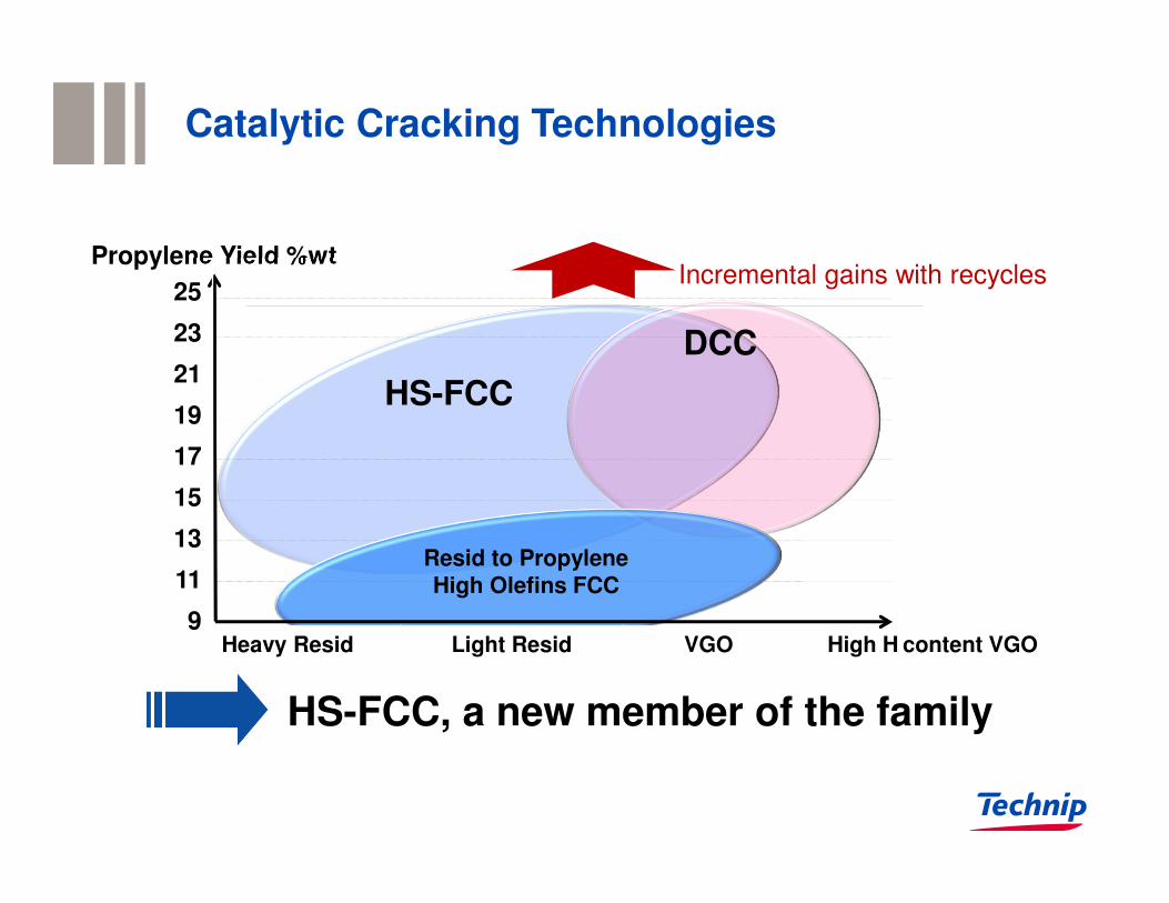
Propylene Yield %wt
HS-FCC
Catalytic Cracking Technologies
DCC
Resid to Propylene High Olefins FCC
Heavy Resid Light Resid VGO High H content VGO
25
23
21
19
17
15
13
11
9
Incremental gains with recycles
HS-FCC, a new member of the family
MaximumPropylene
Yield
MaximumPropylene
Yield
ReactionConditionsReaction
Conditions
ProprietaryCatalyst
ProprietaryCatalyst
UniqueReactionSystem
UniqueReactionSystem
MaximumPropylene
Yield
ReactionConditions
ProprietaryCatalyst
UniqueReactionSystem
HS-FCC™ Technology – Key features
High ROT (580-620°C)
Ultra short contact time (0.5-1s)
High C/O Ratio (25-30)
Rare earth free catalyst
Low acid site density
Patented formula
Downflow reactor
Tempest TM Separator
Technip FIT
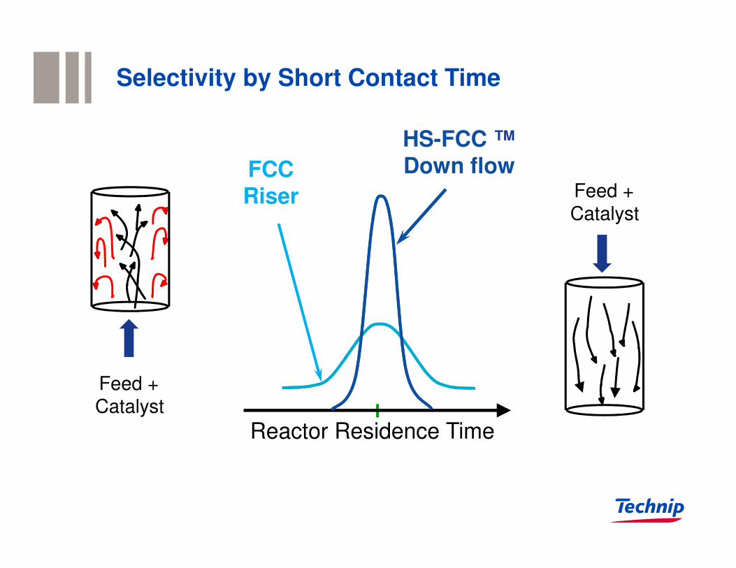
Selectivity by Short Contact Time
HS-FCC ™Down flowFCC
Riser Feed +
Catalyst
Reactor Residence Time
Feed +
Catalyst
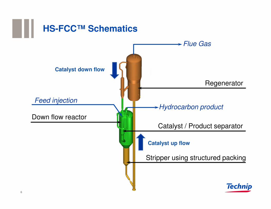
HS-FCC™ Schematics
6
Feed injection
Regenerator
Stripper using structured packing
Catalyst / Product separator
Down flow reactor
Catalyst down flow
Catalyst up flow
Flue Gas
Hydrocarbon product
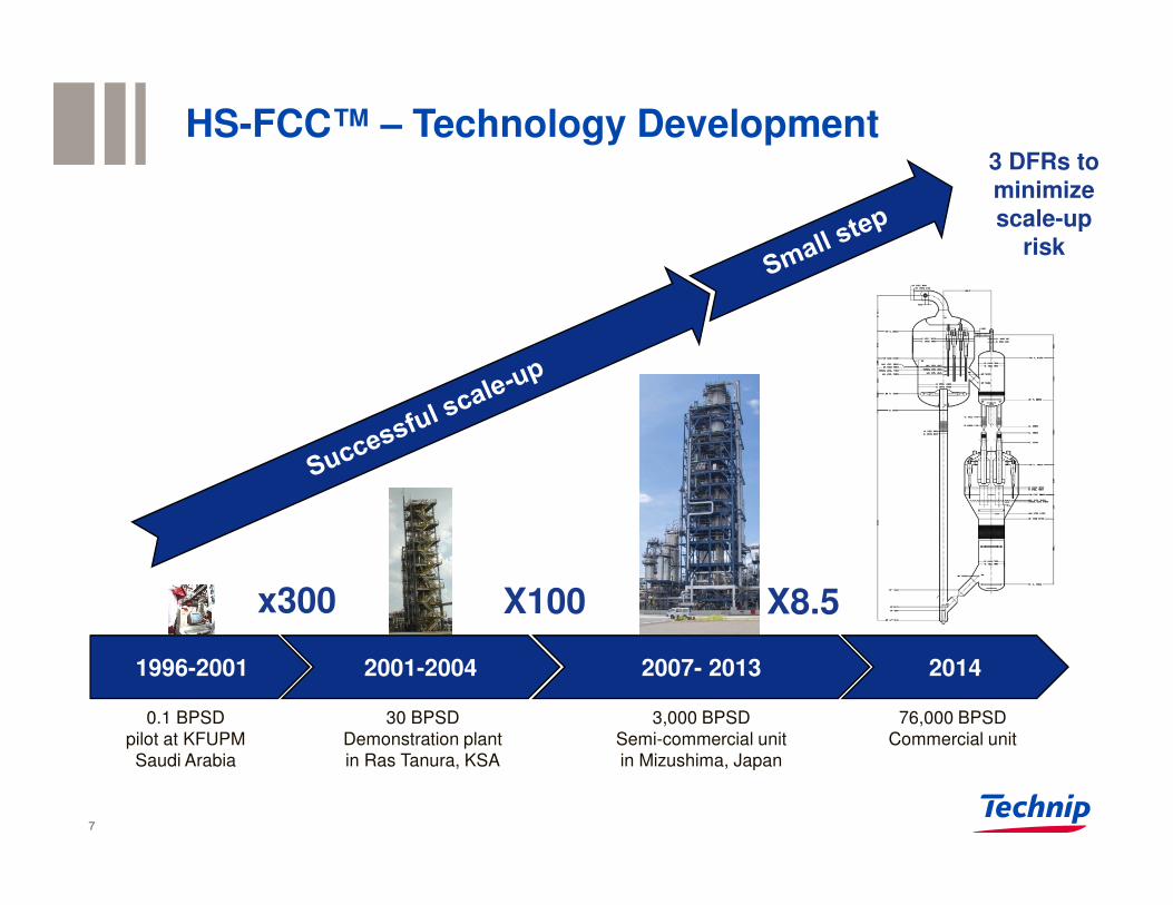
0.1 BPSD
pilot at KFUPM
Saudi Arabia
1996-2001
30 BPSD
Demonstration plant
in Ras Tanura, KSA
2001-2004
3,000 BPSD
Semi-commercial unit
in Mizushima, Japan
2007- 2013 2014
76,000 BPSD
Commercial unit
x300 X100 X8.5
HS-FCC™ – Technology Development
7
3 DFRs to minimizescale-up
risk
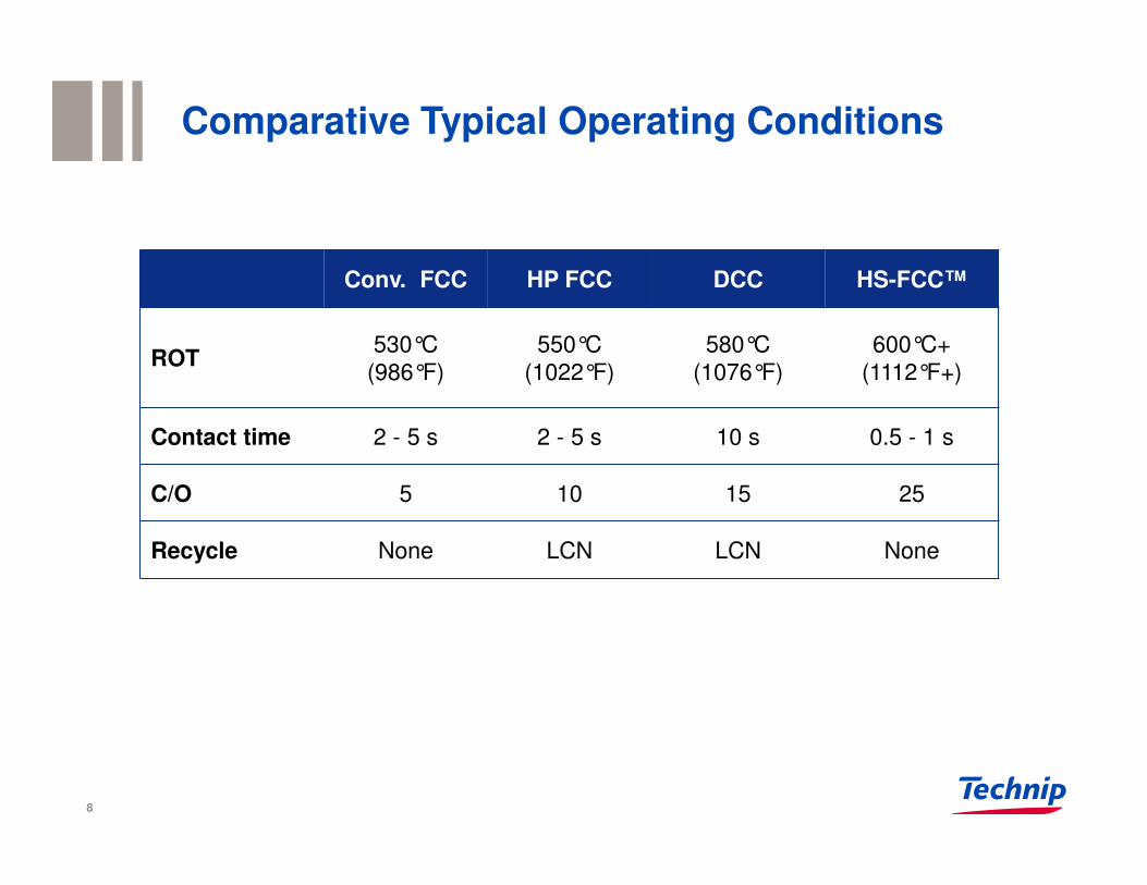
Comparative Typical Operating Conditions
RON93 RON
96 RON98+
Conv. FCC HP FCC DCC HS-FCC™
ROT530°C
(986°F)
550°C
(1022°F)
580°C
(1076°F)
600°C+
(1112°F+)
Contact time 2 - 5 s 2 - 5 s 10 s 0.5 - 1 s
C/O 5 10 15 25
Recycle None LCN LCN None
8
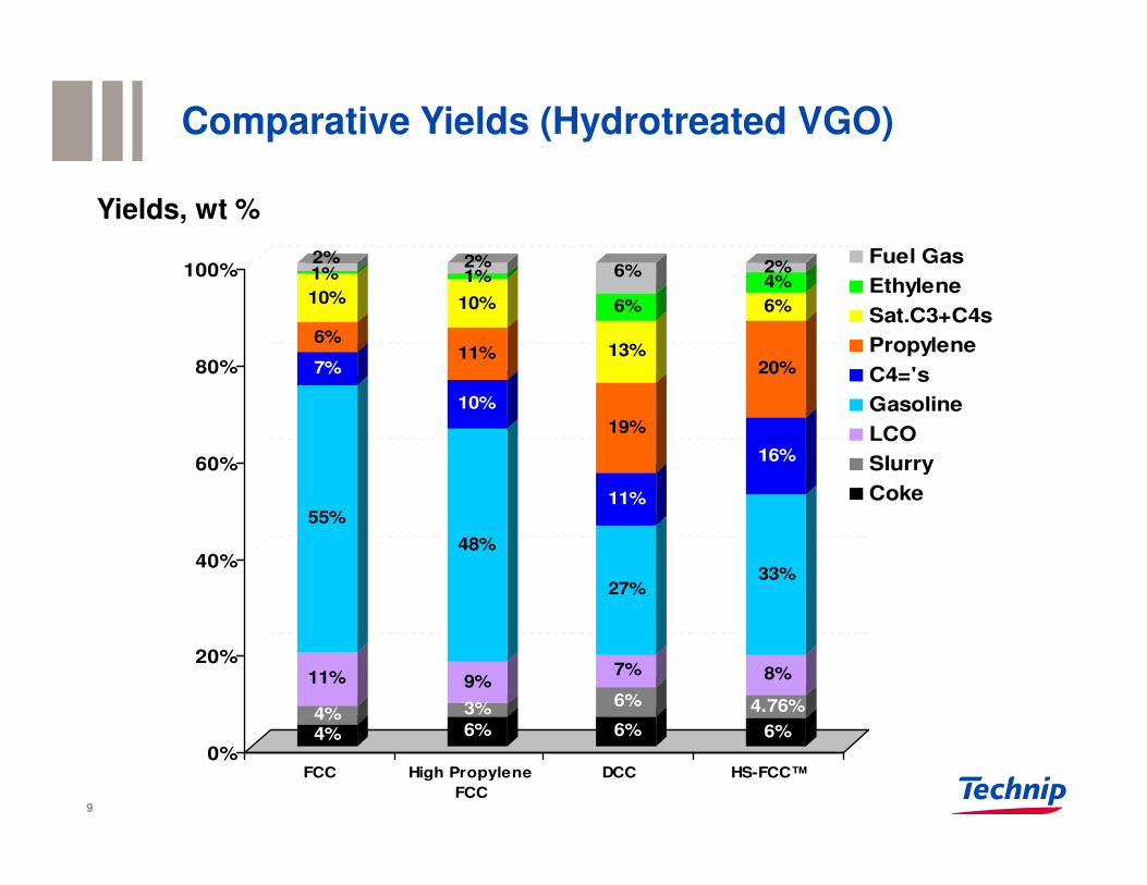
Comparative Yields (Hydrotreated VGO)
4%4%
11%
55%
7%
6%
10%
1%2%
6%
3%
9%
48%
10%
11%
10%
1%2%
6%
6%
7%
27%
11%
19%
13%
6%
6%
6%
4.76%
8%
33%
16%
20%
6%
4%2%
0%
20%
40%
60%
80%
100%
FCC High Propylene
FCC
DCC HS-FCC™
Fuel Gas
Ethylene
Sat.C3+C4s
Propylene
C4='s
Gasoline
LCO
Slurry
Coke
Yields, wt %
9
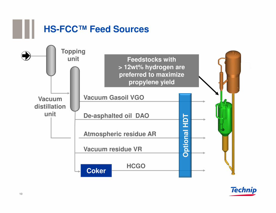
HS-FCC™ Feed Sources
Toppingunit
Vacuumdistillation
unit
Vacuum Gasoil VGO
De-asphalted oil DAO
HCGO
Atmospheric residue AR
Vacuum residue VR
Coker
Feedstocks with> 12wt% hydrogen are preferred to maximize
propylene yield
Op
tio
nal H
DT
10
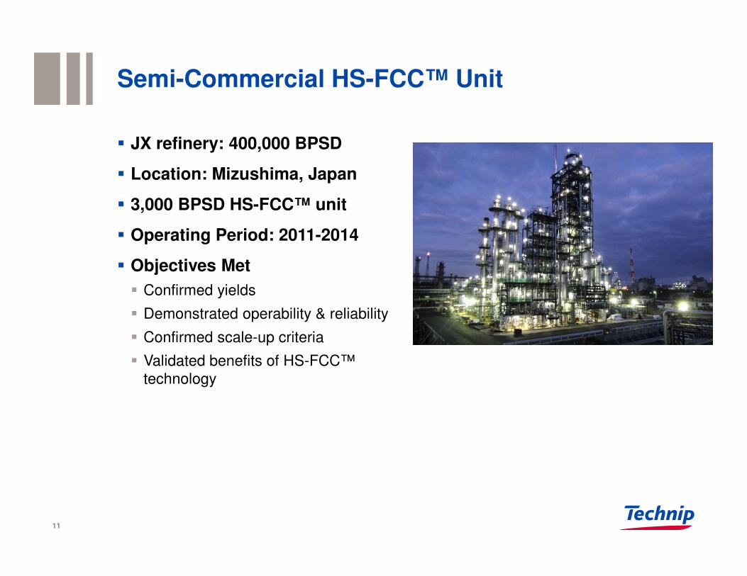
Semi-Commercial HS-FCC™ Unit
� JX refinery: 400,000 BPSD
� Location: Mizushima, Japan
� 3,000 BPSD HS-FCC™ unit
� Operating Period: 2011-2014
� Objectives Met
� Confirmed yields
� Demonstrated operability & reliability
� Confirmed scale-up criteria
� Validated benefits of HS-FCC™
technology
11
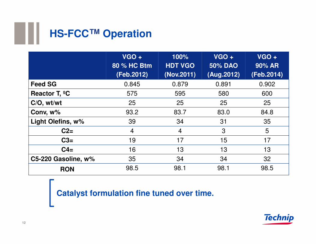
Catalyst formulation fine tuned over time.
HS-FCC™ Operation
VGO +
80 % HC Btm
(Feb.2012)
100%
HDT VGO
(Nov.2011)
VGO +
50% DAO
(Aug.2012)
VGO +
90% AR
(Feb.2014)
Feed SG 0.845 0.879 0.891 0.902
Reactor T, ºC 575 595 580 600
C/O, wt/wt 25 25 25 25
Conv, w% 93.2 83.7 83.0 84.8
Light Olefins, w% 39 34 31 35
C2= 4 4 3 5
C3= 19 17 15 17
C4= 16 13 13 13
C5-220 Gasoline, w% 35 34 34 32
RON 98.5 98.1 98.1 98.5
12
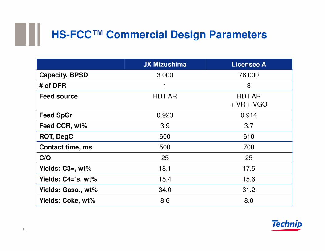
HS-FCC™ Commercial Design Parameters
JX Mizushima Licensee A
Capacity, BPSD 3 000 76 000
# of DFR 1 3
Feed source HDT AR HDT AR
+ VR + VGO
Feed SpGr 0.923 0.914
Feed CCR, wt% 3.9 3.7
ROT, DegC 600 610
Contact time, ms 500 700
C/O 25 25
Yields: C3=, wt% 18.1 17.5
Yields: C4=‘s, wt% 15.4 15.6
Yields: Gaso., wt% 34.0 31.2
Yields: Coke, wt% 8.6 8.0
13
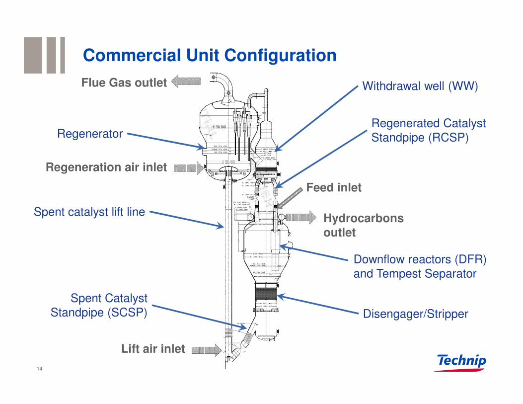
Regeneration air inlet
Commercial Unit Configuration
Regenerator
Spent catalyst lift line
Withdrawal well (WW)
Downflow reactors (DFR)
and Tempest Separator
Disengager/Stripper
Feed inlet
Hydrocarbons outlet
Flue Gas outlet
Lift air inlet
Regenerated Catalyst
Standpipe (RCSP)
Spent Catalyst
Standpipe (SCSP)
14
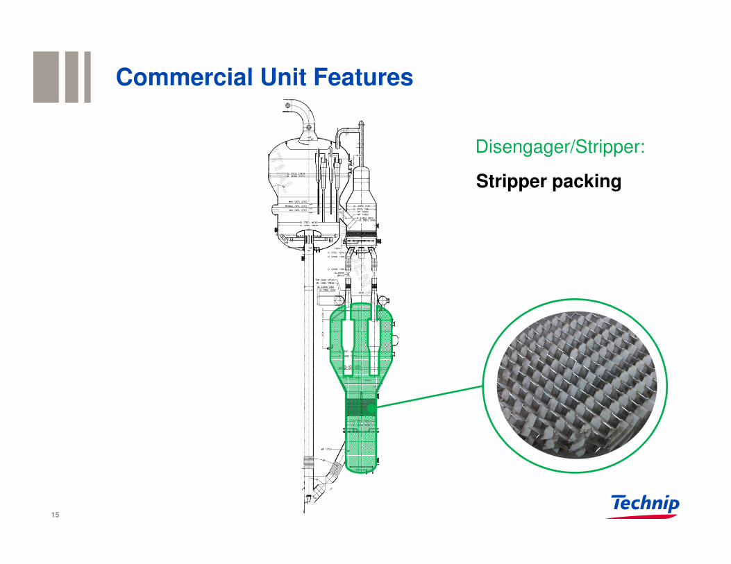
Commercial Unit Features
Disengager/Stripper:
Stripper packing
15
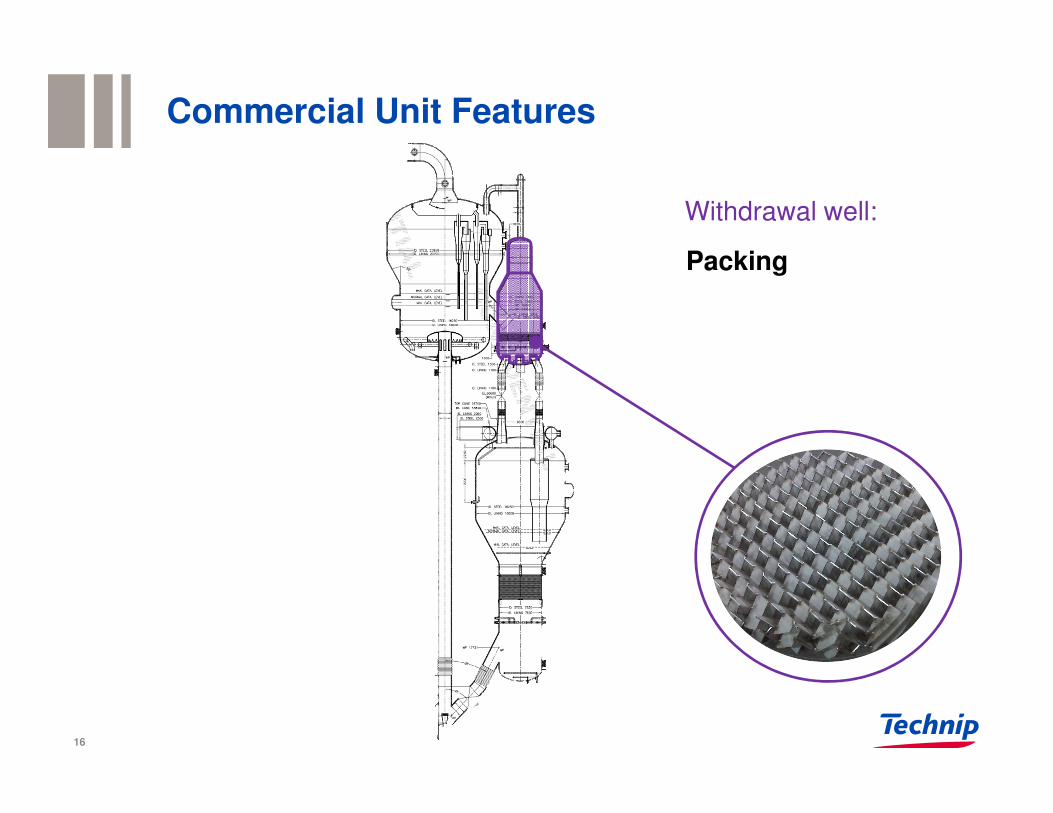
Commercial Unit Features
16
Withdrawal well:
Packing
Commercial Unit FeaturesDownflow reactors:
• Packing• Impact-type feed
injectors• Tempest™ separator
ProductsCatalyst
Catalyst
17
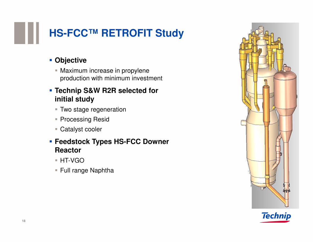
HS-FCC™ RETROFIT Study
� Objective
� Maximum increase in propylene
production with minimum investment
� Technip S&W R2R selected for initial study
� Two stage regeneration
� Processing Resid
� Catalyst cooler
� Feedstock Types HS-FCC Downer Reactor
� HT-VGO
� Full range Naphtha
18
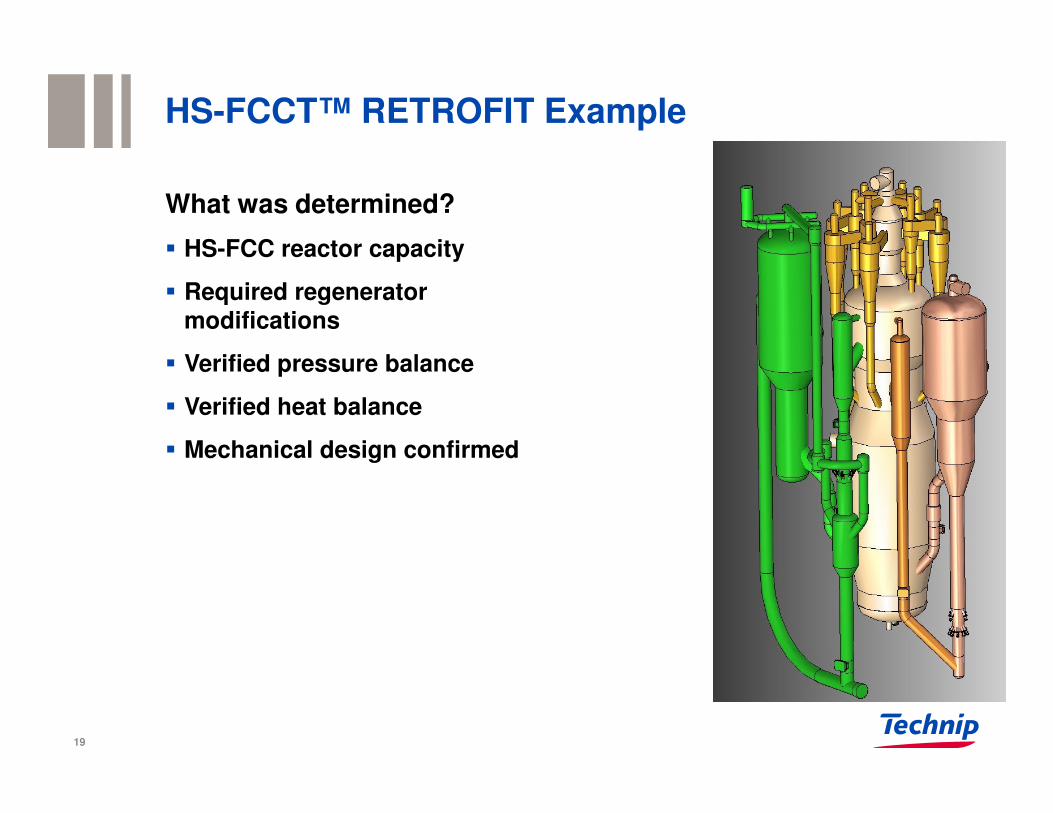
HS-FCCT™ RETROFIT Example
What was determined?
� HS-FCC reactor capacity
� Required regenerator modifications
� Verified pressure balance
� Verified heat balance
� Mechanical design confirmed
19
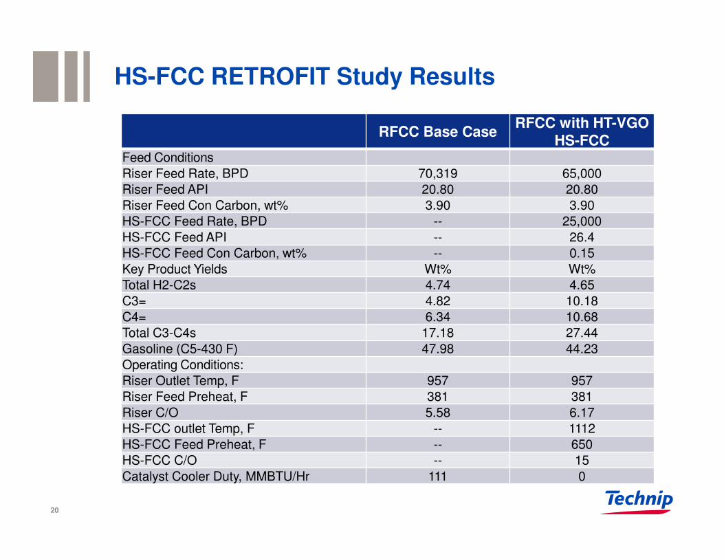
HS-FCC RETROFIT Study Results
RFCC Base CaseRFCC with HT-VGO
HS-FCCFeed Conditions
Riser Feed Rate, BPD 70,319 65,000
Riser Feed API 20.80 20.80
Riser Feed Con Carbon, wt% 3.90 3.90
HS-FCC Feed Rate, BPD -- 25,000
HS-FCC Feed API -- 26.4
HS-FCC Feed Con Carbon, wt% -- 0.15
Key Product Yields Wt% Wt%
Total H2-C2s 4.74 4.65
C3= 4.82 10.18
C4= 6.34 10.68
Total C3-C4s 17.18 27.44
Gasoline (C5-430 F) 47.98 44.23
Operating Conditions:
Riser Outlet Temp, F 957 957
Riser Feed Preheat, F 381 381
Riser C/O 5.58 6.17
HS-FCC outlet Temp, F -- 1112
HS-FCC Feed Preheat, F -- 650
HS-FCC C/O -- 15
Catalyst Cooler Duty, MMBTU/Hr 111 0
20
Conclusion
HS-FCC™ Technology:
� Turns FCC upside down to achieve higher selectivity cracking
� Utilizing high severity-ROT, Cat/oil and catalyst formulation
� Retrofit of existing FCC Units with HS-FCC™ feasible
� Additional retrofit studies in progress
� Offers refinery/petrochemicals integration opportunities for greater profits
� Demonstrated on VGO and resid feedstock in a semi-commercial plant
21
22
Alexander MALLER and Eusebius GBORDZOETechnip Stone & Webster Process TechnologyApril 2016
Technip Stone & Webster Process Technology Offering in RefiningThank you
The material appearing in this presentation is for general information purposes only. Technip S.A. and its affiliated companies ("Technip") assume no responsibility for any errors or omissions in these materials. TECHNIP MAKES NO, AND EXPRESSLY DISCLAIMS ANY, REPRESENTATIONS OR WARRANTIES, EXPRESS OR IMPLIED, REGARDING THE MATERIALS CONTAINED IN THE PRESENTATION, INCLUDING ANY IMPLIED WARRANTIES OF MERCHANTABILITY OR FITNESS FOR A PARTICULAR PURPOSE. Under no circumstances shall Technip, the other sponsors, presenters and any of their respective partners, officers, directors, employees, agents or representatives be liable for any damages, whether direct, indirect, special or consequential, arising from or in connection with the use of materials and information contained in the presentation. The materials contained in this presentation may not be reproduced, republished, distributed, or otherwise exploited in any manner without the express prior written permission of Technip.