Caleb Fisher, Glenn Research Center Techniques for Preparing Pro/Engineer Models for CFdesign Fluid Flow and Convective Heat Transfer Analysis Caleb D. Fisher NASA John Glenn Research Center TFAWS 2005
Transcript
Caleb Fisher, Glenn Research Center
Techniques for Preparing Pro/Engineer Models for CFdesign Fluid Flow and Convective Heat Transfer Analysis
Caleb D. FisherNASA
John Glenn Research Center
TFAWS 2005
2Caleb Fisher, Glenn Research Center
Outline
I. IntroductionII. Simplifying model geometryIII. Creating fluid volumesIV. Utilizing Mechanica Volume Regions
3Caleb Fisher, Glenn Research Center
Background
• ISS Avionics Box (Engineering Model)– Tasked with conducting thermal analysis– Needed more than “back of the envelope”– Pro/E model set up for design and manufacturing,
not analysis– Model complexity surpassed that of previous
CFdesign analyses– Result: Many lessons learned regarding
simplifying complex models and constructing models w/ analysis in mind
– Currently supporting redesign for flight• Techniques emphasize flow/convection
4Caleb Fisher, Glenn Research Center
Benefits of Coupling Pro/Engineer With CFdesign
• Geometry not lost or skewed by approximation– Analysis utilizes the model by which the hardware
will be constructed• True associative relationship between design
and analysis– Time and accuracy not sacrificed for rebuilding or
updating analysis model• Greater fidelity in preliminary design stage
– Design engineer can do much better than “back of the envelope” without employing a CFD PhD
• Geometry analyzed by CFdesign needs only to be displayed in Pro/E environment– Avoids undesirable effects due to suppressing or
deleting components not needed for analysis (even when “stepping”)
7Caleb Fisher, Glenn Research Center
Simplifying Model Geometry
• Using ‘Simplified Reps’ in Pro/Engineer– Selected components are contained in single
group which can be quickly hidden/redrawn– Reverting to previous configuration is 100%
accurate– Multiple Simplified Reps are easily created and
managed– View-based; no effect on actual model geometry
• Simplified Rep Creation (Wildfire 2.0)1. Select components to be removed from view2. Pick “View-Representation-Exclude”3. Run the View Manager, pick “Simp Rep”, and
enter a name for new rep
8Caleb Fisher, Glenn Research Center
Creating a Simplified Rep
9Caleb Fisher, Glenn Research Center
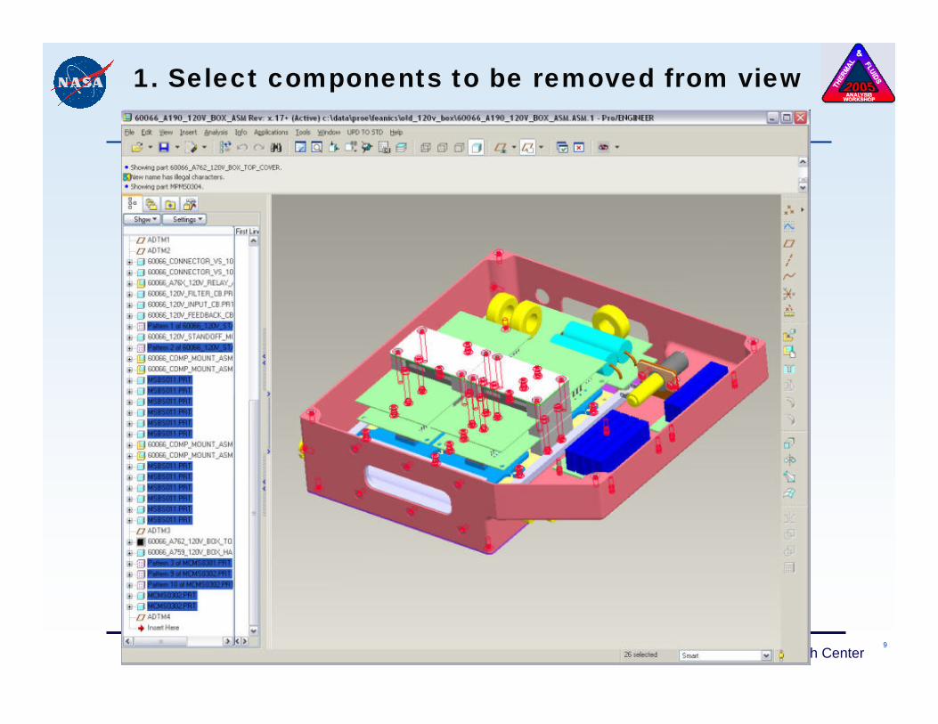
1. Select components to be removed from view
10Caleb Fisher, Glenn Research Center
2. Pick “View-Representation-Exclude”
11Caleb Fisher, Glenn Research Center
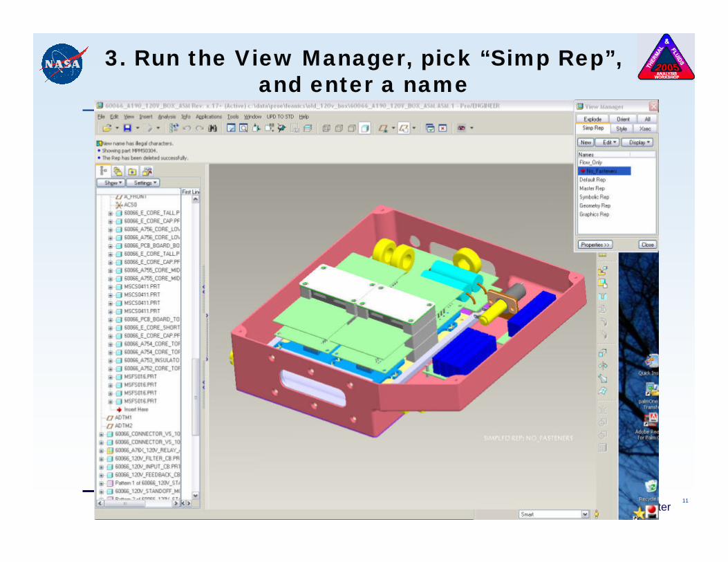
3. Run the View Manager, pick “Simp Rep”, and enter a name
12Caleb Fisher, Glenn Research Center
Simplifying Model Geometry
Reiterating benefits of ‘Simplified Reps’:– Selected components are contained in single
group which can be quickly hidden/redrawn– Reverting to previous configuration is 100%
accurate– Multiple Simplified Reps are easily created and
managed– View-based; no effect on actual model geometry
13Caleb Fisher, Glenn Research Center
Simplifying Model Geometry
Checking for remaining geometric interferences:1. “Analysis - Model Analysis”2. “Type” = Global Interference3. Leave defaults “Compute”4. “Info” will produce full text5. Exclude components from simplified rep on case-
by-case basis (ugh)
14Caleb Fisher, Glenn Research Center
Creating Fluid Volumes
15Caleb Fisher, Glenn Research Center
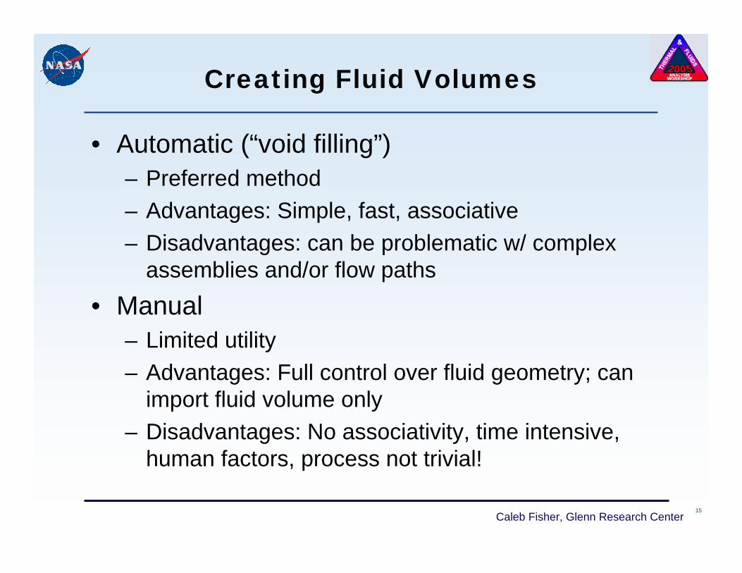
Creating Fluid Volumes
• Automatic (“void filling”)– Preferred method– Advantages: Simple, fast, associative– Disadvantages: can be problematic w/ complex
assemblies and/or flow paths• Manual
– Limited utility– Advantages: Full control over fluid geometry; can
import fluid volume only– Disadvantages: No associativity, time intensive,
human factors, process not trivial!
16Caleb Fisher, Glenn Research Center
Creating Fluid Volumes: Automatic
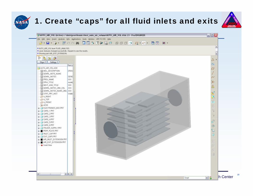
Process:1. Create “caps” for all fluid inlets and exits
a) No internal components can protrude into capsb) Caps must be flush with existing solid geometry
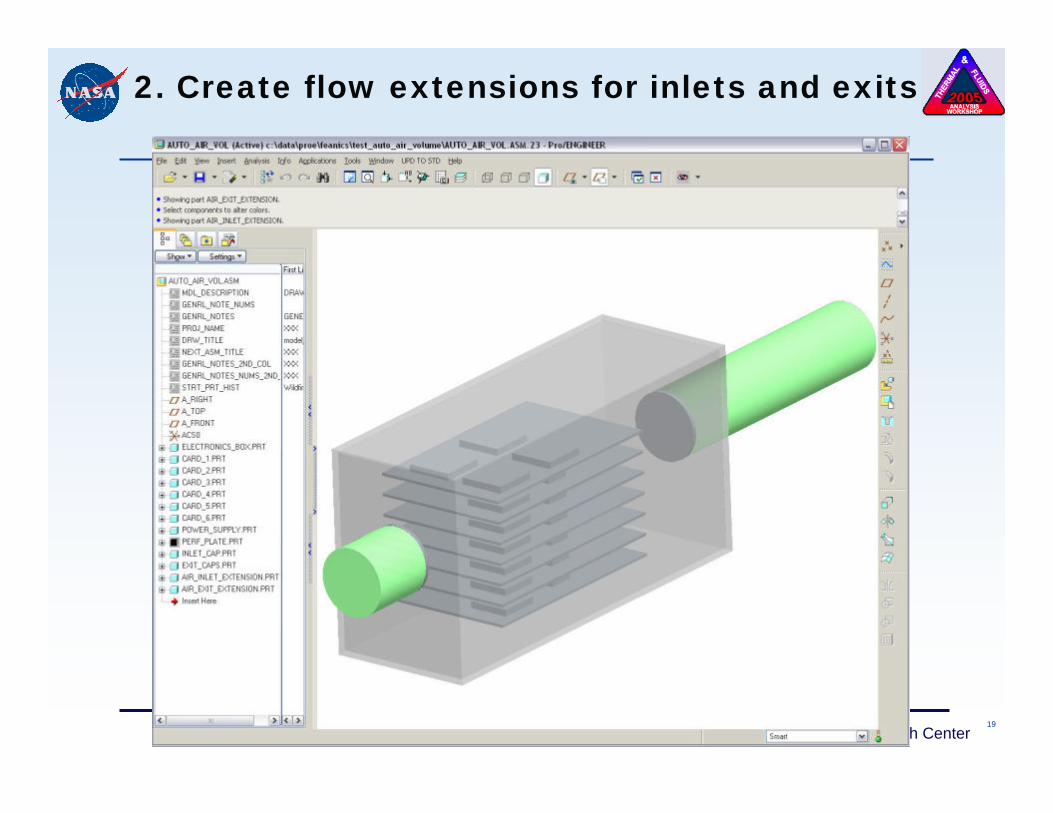
2. Create flow extensions for inlets and exitsa) Promotes analysis convergence (CFdesign assumes
fully-developed flow)b) Exit is mandatory; inlet is optionalc) Extrude directly from caps when practical
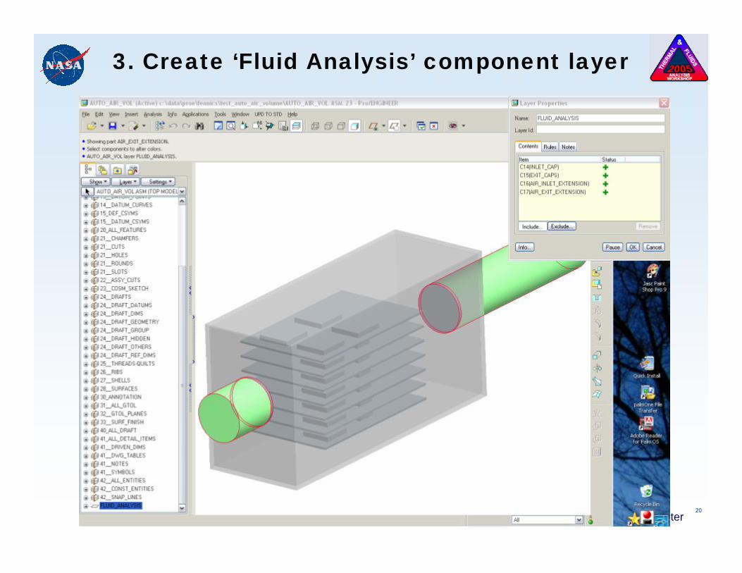
3. Create ‘Fluid Analysis’ component layer and transfer recently-created componentsa) Isolates solid geometry not part of actual hardware
17Caleb Fisher, Glenn Research Center
Generic Electronics Box
18Caleb Fisher, Glenn Research Center
1. Create “caps” for all fluid inlets and exits
19Caleb Fisher, Glenn Research Center
2. Create flow extensions for inlets and exits
20Caleb Fisher, Glenn Research Center
3. Create ‘Fluid Analysis’ component layer
21Caleb Fisher, Glenn Research Center
Creating Fluid Volumes: Automatic
4. Ready for import into CFdesign
A couple tips:– “PROTOOL FILLVOIDS 1” must be set in
cfdesign_flags.txt– Be aware of effects on model properties, such as
overall mass and BOM
22Caleb Fisher, Glenn Research Center
Creating Fluid Volumes: Manual
In a nutshell:1. Create a “bulk” fluid volume2. “Cut out” flow paths using existing components
Specifically:1. Create simplified reps of all sub-assemblies2. Create geometric “Shrinkwrap” of each simplified
rep3. Assemble shrinkwrapped components into a new
assembly for making “cut-outs”4. Create a bulk fluid volume (in above assembly)5. Cut to final shape using “Adv.Util – Cut Out”
23Caleb Fisher, Glenn Research Center
Creating Fluid Volumes: Manual
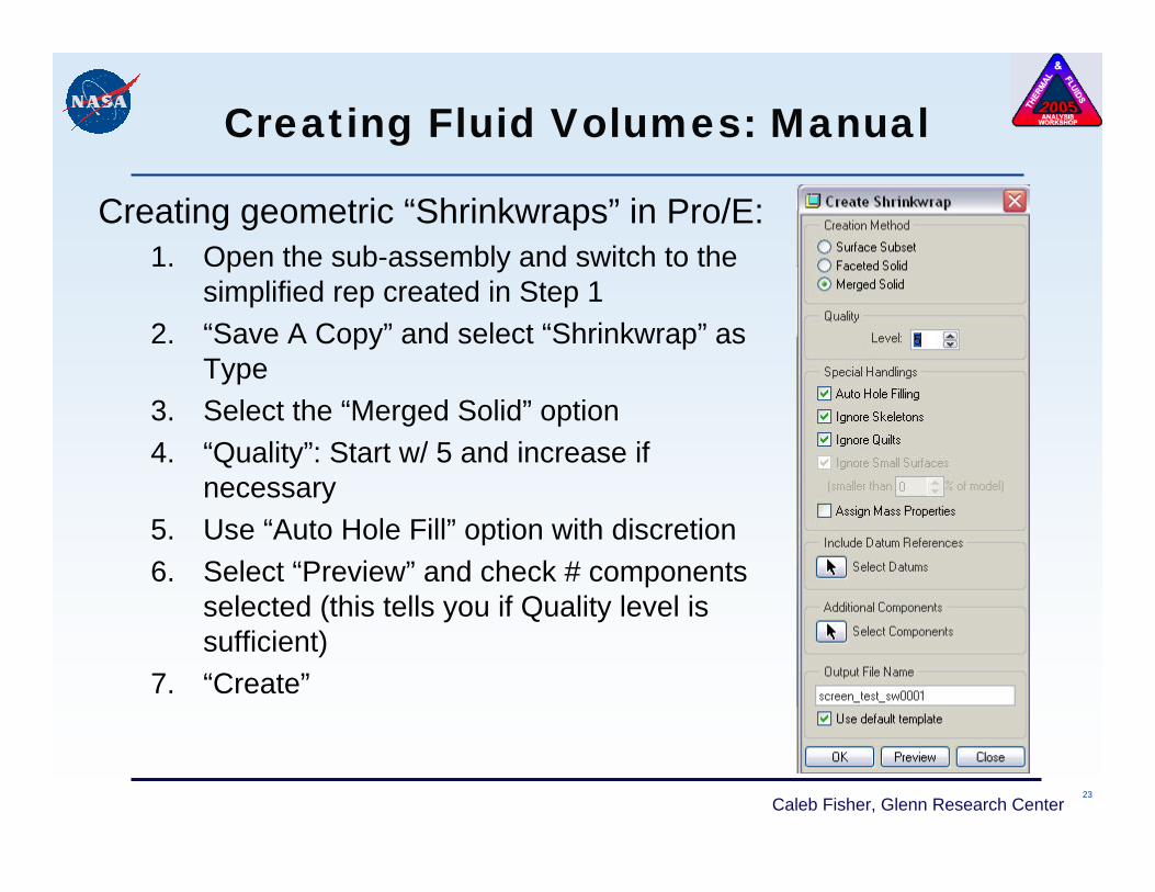
Creating geometric “Shrinkwraps” in Pro/E:1. Open the sub-assembly and switch to the
simplified rep created in Step 12. “Save A Copy” and select “Shrinkwrap” as
Type3. Select the “Merged Solid” option4. “Quality”: Start w/ 5 and increase if
necessary 5. Use “Auto Hole Fill” option with discretion6. Select “Preview” and check # components
selected (this tells you if Quality level is sufficient)
7. “Create”
24Caleb Fisher, Glenn Research Center
Creating Fluid Volumes: Manual
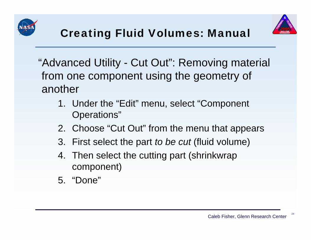
“Advanced Utility - Cut Out”: Removing material from one component using the geometry of another
1. Under the “Edit” menu, select “Component Operations”
2. Choose “Cut Out” from the menu that appears3. First select the part to be cut (fluid volume)4. Then select the cutting part (shrinkwrap
component)5. “Done”
25Caleb Fisher, Glenn Research Center
Utilizing Mechanica Volume Regions
26Caleb Fisher, Glenn Research Center
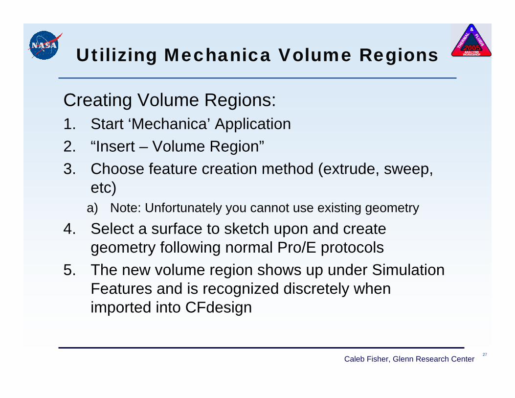
Utilizing Mechanica Volume Regions
Uses for Volume Regions in CFdesign:– Segregating complex volumes to allow for more
discrete assignment of:• Boundary and initial conditions• Thermal, fluid, and other material properties
– Modeling and analyzing screens/meshes/flow resistances• Simplifies solid model, thus reducing overhead• Improves analysis accuracy and promotes analysis
convergence• Allows efficient trade studies regarding FAR’s using
CFdesign’s ‘Design Center’– Note: In order for CFdesign to recognize the
volume regions, they can neither overlap nor share a surface